Embed Size (px)
Citation preview

SP3D Live Online Webinar with Multisoft Virtual Academy!!!
Website: www.multisoftvirtualacademy.com Email: [email protected] Contact No: +918130666206/209
Contents
• Introduction • Task Menu • Format Menu • Aspects • Equipment and Furnishings Workflow • Piping Workflow • Structure Workflow • Supports Workflow • Electrical Workflow • HVAC Workflow • Deliverables
Introduction
3
SmartPlant 3D is Intergraph Process, Power & Marine's next generation, data-centric, rule-driven solution for streamlining engineering design process while preserving existing data and making it more usable/re-usable.
A member of Intergraph's SmartPlant family of products,
SmartPlant 3D is a complementary, full-suite solution that provides all the capabilities needed to design a plant, and then keep it as-built throughout its lifecycle.
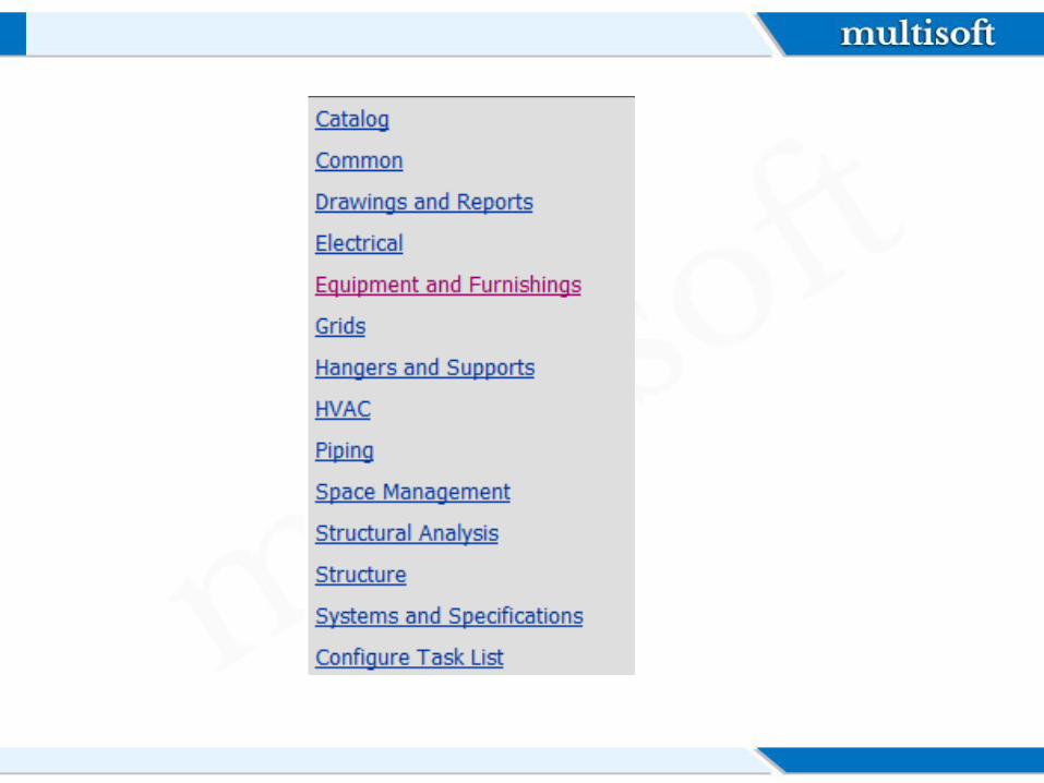
The software uses tasks to separate its user interface into discipline-specific user environments.
Tasks are sets of commands focused on a particular engineering discipline, such as routing pipe or placing equipment.
You usually need only a few of these tasks to accomplish your particular job. For example, if you are a piping designer, you probably only need to use the tasks that allow you to route pipe or create isometric drawings.
Task Menu
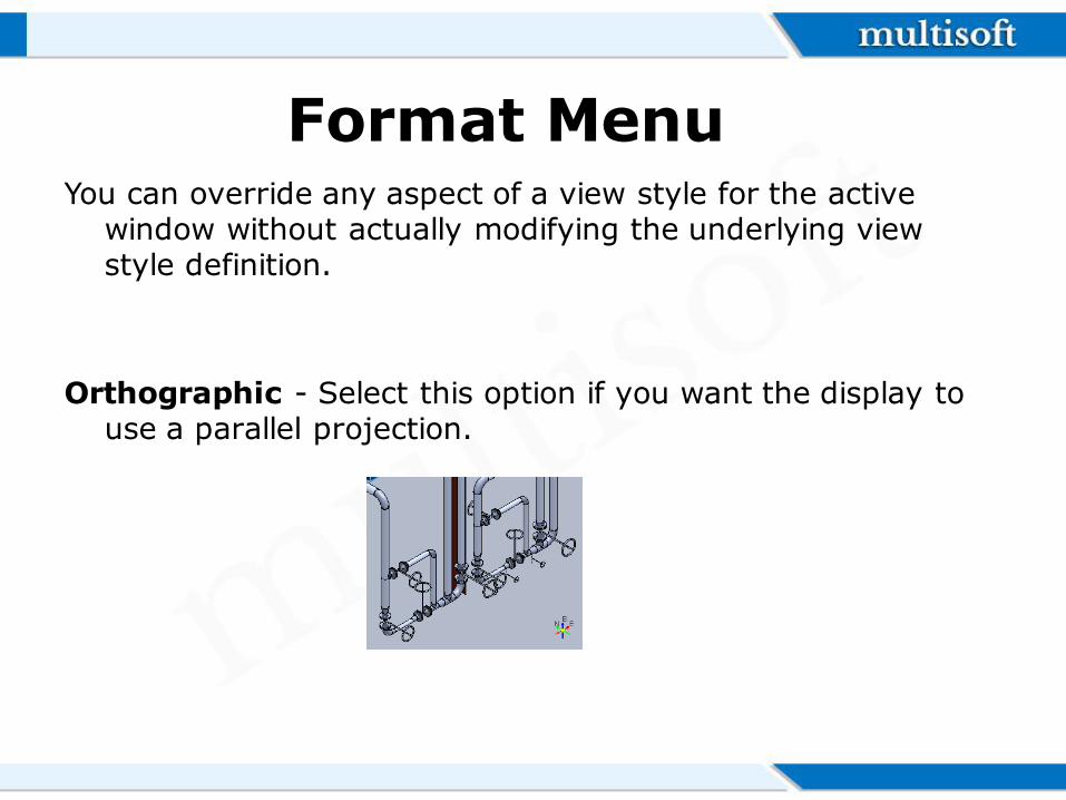
You can override any aspect of a view style for the active window without actually modifying the underlying view style definition.
Orthographic - Select this option if you want the display to use a parallel projection.
Format Menu
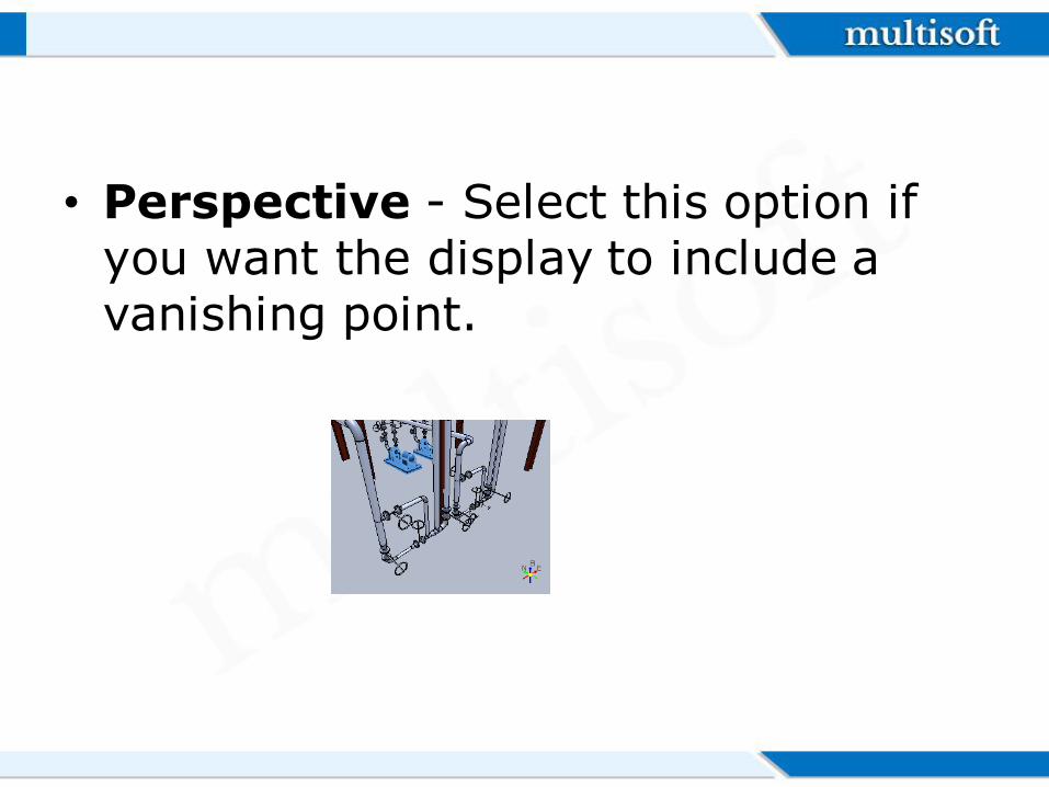
• Perspective - Select this option if you want the display to include a vanishing point.
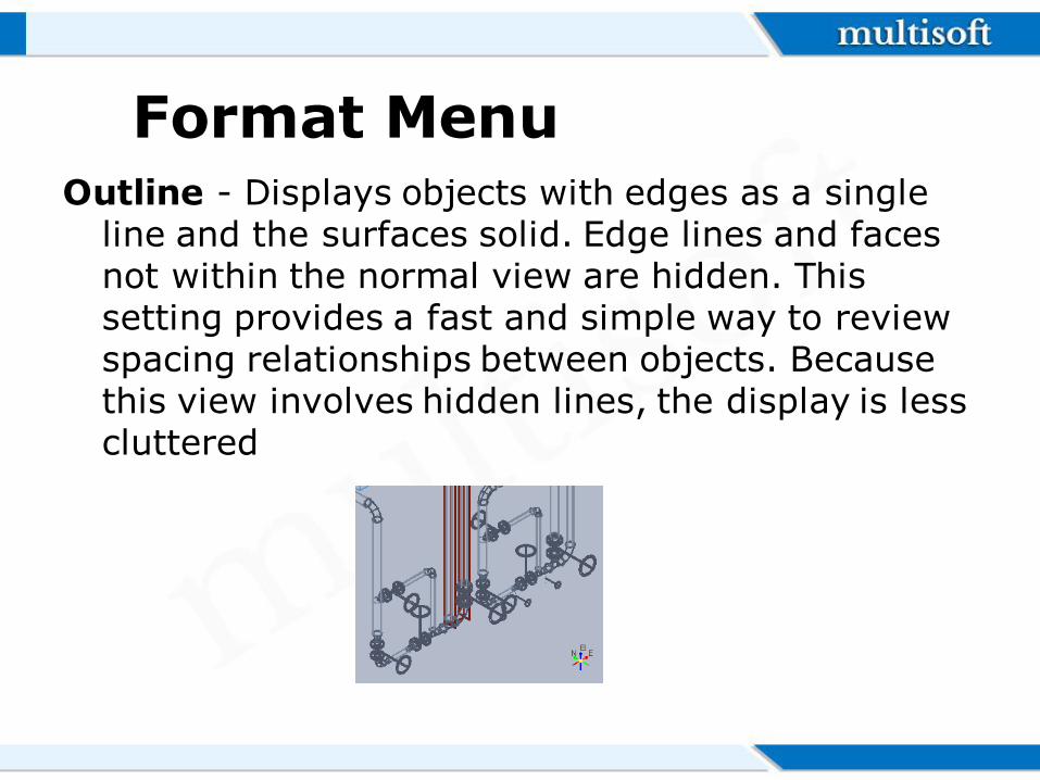
Outline - Displays objects with edges as a single line and the surfaces solid. Edge lines and faces not within the normal view are hidden. This setting provides a fast and simple way to review spacing relationships between objects. Because this view involves hidden lines, the display is less cluttered
Format Menu
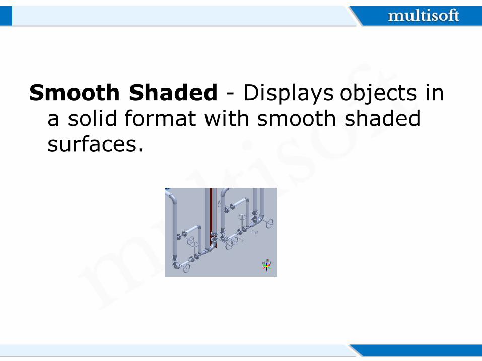
Smooth Shaded - Displays objects in a solid format with smooth shaded surfaces.
Aspects
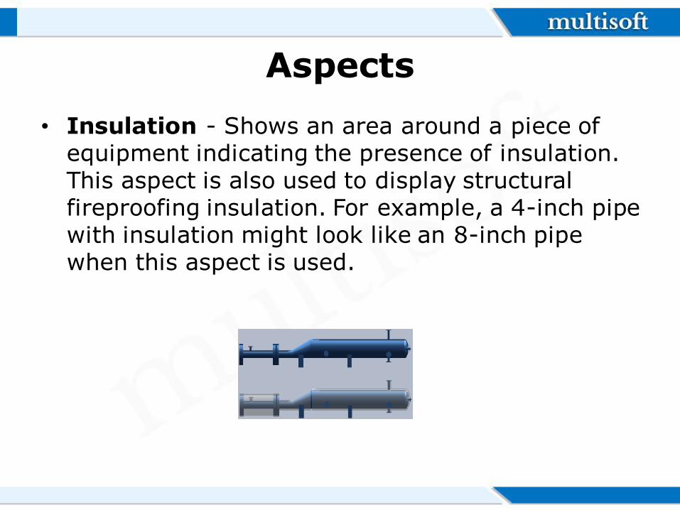
• Insulation - Shows an area around a piece of equipment indicating the presence of insulation. This aspect is also used to display structural fireproofing insulation. For example, a 4-inch pipe with insulation might look like an 8-inch pipe when this aspect is used.
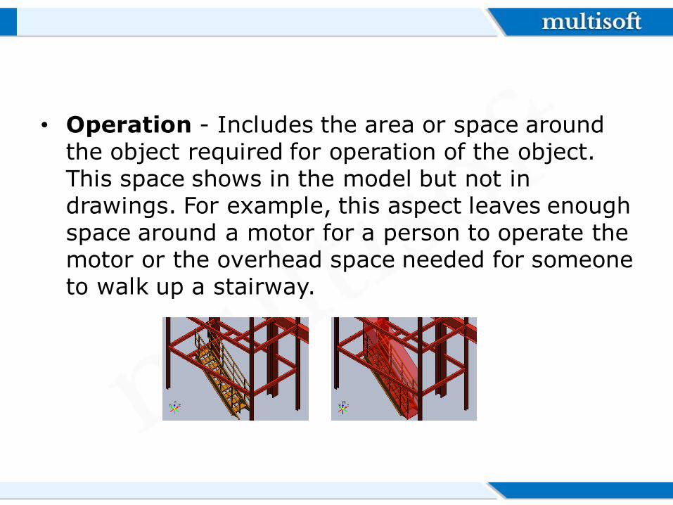
• Operation - Includes the area or space around the object required for operation of the object. This space shows in the model but not in drawings. For example, this aspect leaves enough space around a motor for a person to operate the motor or the overhead space needed for someone to walk up a stairway.
Aspects
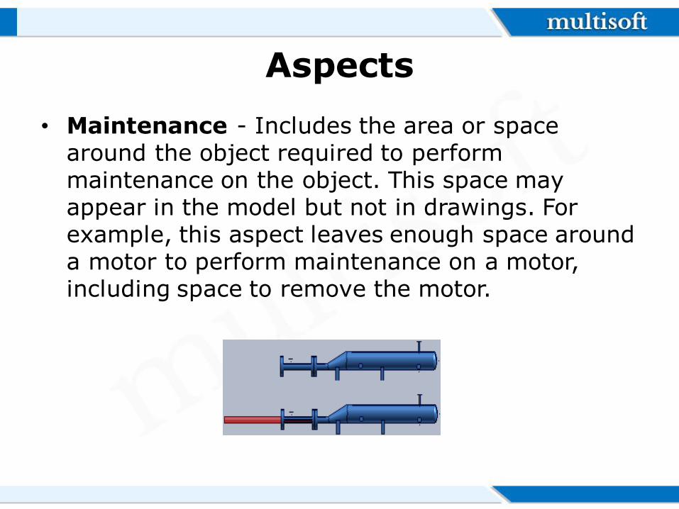
• Maintenance - Includes the area or space around the object required to perform maintenance on the object. This space may appear in the model but not in drawings. For example, this aspect leaves enough space around a motor to perform maintenance on a motor, including space to remove the motor.
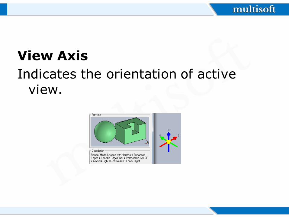
View Axis
Indicates the orientation of active view.
Equipment and Furnishings Workflow
All equipment objects are placed in the model using information defined in the equipment and furnishings task. Using this, you can create custom equipment objects.
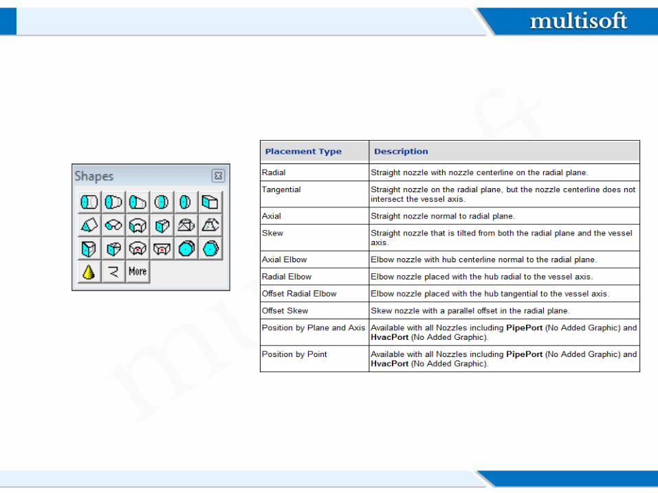
You can interactively customize equipment from the Catalog by adding primitive geometric shapes and nozzles
You can also use the Equipment and Furnishings task to build customized equipment. Designed equipment objects can be built entirely out of primitive geometric shapes, or an equipment component part can be designed or placed from the catalog to enhance the designed equipment object.
Equipment components provide a more precise method of building up designed equipment.
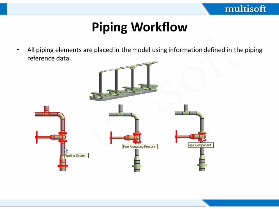
Piping Workflow
• All piping elements are placed in the model using information defined in the piping reference data.
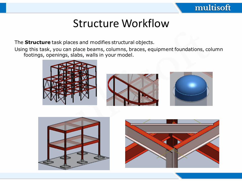
Structure Workflow
The Structure task places and modifies structural objects.
Using this task, you can place beams, columns, braces, equipment foundations, column footings, openings, slabs, walls in your model.
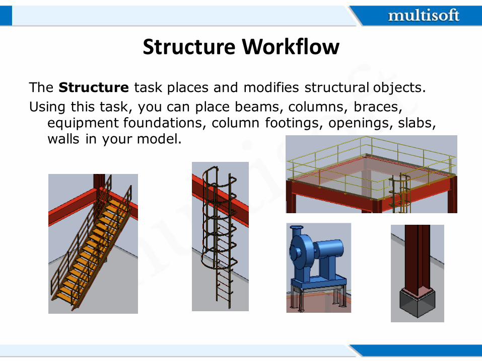
Structure Workflow
The Structure task places and modifies structural objects.
Using this task, you can place beams, columns, braces, equipment foundations, column footings, openings, slabs, walls in your model.
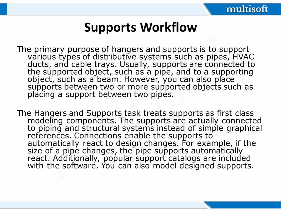
Supports Workflow
The primary purpose of hangers and supports is to support various types of distributive systems such as pipes, HVAC ducts, and cable trays. Usually, supports are connected to the supported object, such as a pipe, and to a supporting object, such as a beam. However, you can also place supports between two or more supported objects such as placing a support between two pipes.
The Hangers and Supports task treats supports as first class
modeling components. The supports are actually connected to piping and structural systems instead of simple graphical references. Connections enable the supports to automatically react to design changes. For example, if the size of a pipe changes, the pipe supports automatically react. Additionally, popular support catalogs are included with the software. You can also model designed supports.
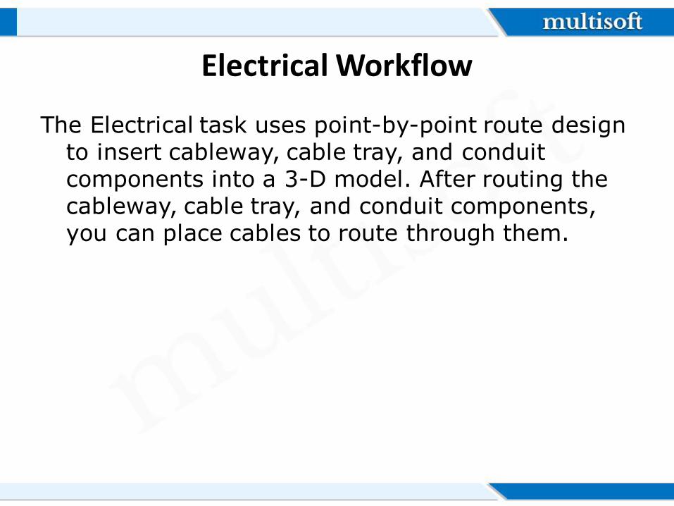
Electrical Workflow
The Electrical task uses point-by-point route design to insert cableway, cable tray, and conduit components into a 3-D model. After routing the cableway, cable tray, and conduit components, you can place cables to route through them.
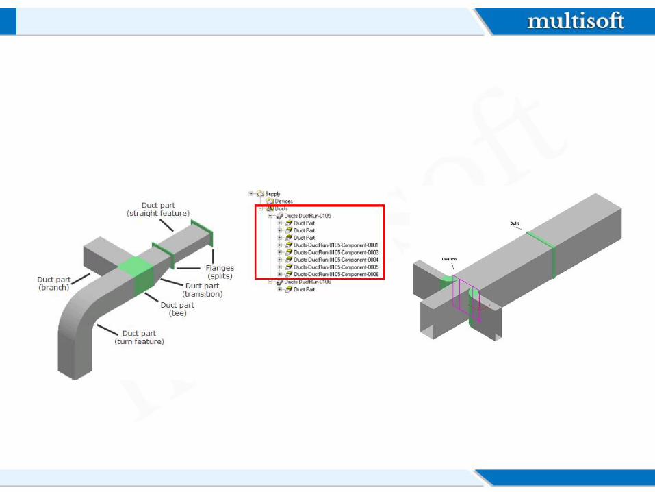
HVAC Workflow
The HVAC task creates a three-dimensional representation, or model, of a distributed system so that you can create a fully rendered 3-D model of various duct systems. You use a combination of parts and features, objects that define the geometry and design intent of a run, to model the duct runs that comprise the duct system. In the software hierarchy, a feature is a child to a run and a parent to a part.
Deliverables
The Drawings and Reports task creates orthographic drawings (by a variety of methods), isometric drawings, and reports from the model. When the 3D model changes, you can update your drawings and reports.
Drawings by Query Manager
Creates a Drawings by Query Manager in the Console. The Drawings by Query Manager provides the filter that specifies the "where" side of the query. It tells the query "where" to look for the objects specified by the component "what" filter.
Composed Drawings
Composed drawings are orthographic drawings created in a 3D task such as Common. The composed drawing component, available in the Drawing and Reports task Management Console, manages the composed drawings you create. Composed drawings are flexible, allowing you to have views that are managed by a drawing region and associate the views to volumes and other views.
Volume Drawings
Volume drawings are useful for creating general arrangement or construction drawings of areas within the model
Reports
In the Spreadsheet Reports workflow, you create report templates, which control the content and format of reports. The default file format of reports in the software is Microsoft Excel format.
• Q&A

Thank You!
Website: www.multisoftvirtualacademy.com Email: [email protected] Contact No: +918130666206/209