Embed Size (px)
Citation preview

Heriot-Watt University Research Gateway
Space Matching for Highly Efficient Microwave Wireless PowerTransmission Systems
Citation for published version:Lu, P, Huang, K, Yang, Y, Zhang, B, Cheng, F & Song, C 2021, 'Space Matching for Highly EfficientMicrowave Wireless Power Transmission Systems: Theory, Prototype, and Experiments', IEEETransactions on Microwave Theory and Techniques, vol. 69, no. 3, pp. 1985-1998.https://doi.org/10.1109/TMTT.2021.3053969
Digital Object Identifier (DOI):10.1109/TMTT.2021.3053969
Link:Link to publication record in Heriot-Watt Research Portal
Document Version:Peer reviewed version
Published In:IEEE Transactions on Microwave Theory and Techniques
Publisher Rights Statement:© 2021 IEEE. Personal use of this material is permitted. Permission from IEEE must be obtained for all otheruses, in any current or future media, including reprinting/republishing this material for advertising or promotionalpurposes, creating new collective works, for resale or redistribution to servers or lists, or reuse of anycopyrighted component of this work in other works.
General rightsCopyright for the publications made accessible via Heriot-Watt Research Portal is retained by the author(s) and /or other copyright owners and it is a condition of accessing these publications that users recognise and abide bythe legal requirements associated with these rights.
Take down policyHeriot-Watt University has made every reasonable effort to ensure that the content in Heriot-Watt ResearchPortal complies with UK legislation. If you believe that the public display of this file breaches copyright pleasecontact [email protected] providing details, and we will remove access to the work immediately andinvestigate your claim.
Download date: 18. Dec. 2021

This article has been accepted for inclusion in a future issue of this journal. Content is final as presented, with the exception of pagination.
IEEE TRANSACTIONS ON MICROWAVE THEORY AND TECHNIQUES 1
Space Matching for Highly Efficient MicrowaveWireless Power Transmission Systems: Theory,
Prototype, and ExperimentsPing Lu , Member, IEEE, Kama Huang, Senior Member, IEEE, Yang Yang , Member, IEEE,
Bing Zhang, Senior Member, IEEE, Fei Cheng , and Chaoyun Song, Member, IEEE
Abstract— Microwave wireless power transmission (MWPT)via radio waves has been an important research topic of theWPT systems, where the overall power transfer and conversionefficiency is a key factor to evaluate the system performance.The state-of-the-art work on MWPT has only taken the end-to-end power transfer efficiency in free space or the powerconversion efficiency of the receiver (rectenna) into considerationseparately when optimizing the power transfer efficiency of theoverall system. To comprehensively consider the system-levelmatching of the entire MWPT system, a novel space matchingconcept, including aperture field matching, power matching,and impedance matching, is proposed for optimizing the overallpower transfer efficiency. By using the space matching method inthis work, the optimal designs of the subsystem components suchas the transmitting antenna, receiving antenna, and rectifyingcircuit can be separately obtained to avoid the complex systematicoptimization of the large-scale and complicated MWPT system,therefore, significantly improving the overall power transferefficiency by 19.4% compared with the traditional methods, andreducing the complexity in large-scale system-level design. Thiswork will have valuable implications in the system design ofMWPT applications.
Index Terms— Microwave wireless power transmission(MWPT), power transfer and conversion efficiency (PTCE),rectenna array, separate optimization, space matching concept.
I. INTRODUCTION
M ICROWAVE wireless power transmission (MWPT) sys-tems, which deliver radio frequency (RF) power in free
space from transmitter (TX) to receiver (RX) without using
Manuscript received August 19, 2020; revised November 26, 2020 andDecember 30, 2020; accepted January 6, 2021. This work was sup-ported in part by the National Natural Science Foundation of China underGrant 51907130 and Grant 61931009; in part by the Postdoctoral ScienceFoundation of China under Grant 20504153007; in part by the SichuanScience and Technology Program under Grant 2020YFH0091; in part by theChengdu Science and Technology Program under Grant 2020-GH02-00036-HZ; and in part by the Fundamental Research Funds for the Central Univer-sities under Grant 20504153015. (Corresponding author: Kama Huang.)
Ping Lu, Kama Huang, Yang Yang, Bing Zhang, and Fei Cheng arewith the School of Electronics and Information Engineering, SichuanUniversity, Chengdu 610064, China (e-mail: [email protected];[email protected]; [email protected]; [email protected];[email protected]).
Chaoyun Song is with the School of Engineering and PhysicalSciences, Heriot-Watt University, Edinburgh EH14 4AS, U.K. (e-mail:[email protected]).
Color versions of one or more figures in this article are available athttps://doi.org/10.1109/TMTT.2021.3053969.
Digital Object Identifier 10.1109/TMTT.2021.3053969
wire, are becoming increasingly attractive in many application,such as communication, medical treatment, and industrialrealms [1]–[3]. In a typical MWPT system, the overall powertransfer and conversion efficiency (PTCE) is defined using theratio of the output dc power across the load to the transmittedpower of the transmitting antenna. More specifically, the PTCEcontaining the power transmission efficiency in free space andthe RF–dc conversion efficiency of the rectenna, is typicallyused to evaluate the performance of the traditional MWPTsystem. For a wired circuit, only the impedance matchingbetween the source and load will need to be considered wherethe load impedance and the source impedance should achievea conjugate matching condition for the maximum power deliv-ery [5]. Due to the nonlinearity of the rectifier and the radiowave propagation in space, the matching between the TX andRX in the MWPT system becomes more complicated than thatof a wired circuit. To improve the PTCE, the space matchingof the whole MWPT system should be fully considered.
In terms of the power transmission efficiency in freespace, some theories to maximize the power transmissionwere proposed by several groups [7]–[9]. The transmissionefficiency between the TX and RX with the same or differentapertures was surveyed. Besides, the procedure to design ahighly efficient MWPT system at arbitrary distance from themicrowave generator to the receiving aperture was given in [7].However, in these designs, the ideal apertures (e.g., no apertureefficiency drop) were assumed for TX and RX rather than theactual antennas. Especially, in MWPT system, the RX is notsimply formed using an antenna array, and it is connected tothe nonlinear rectifying circuit to form the rectenna array.
Some methods to improve PTCE of the MWPT systemwere proposed. One is to optimize the aperture field dis-tribution for improving the transmission efficiency in freespace [10]–[13]. To achieve high transmission efficiency infree space, the isosceles trapezoidal distribution (ITD) of arrayexcitation was investigated to achieve the maximum beam col-lection efficiency [10], [11]. Besides, some transmitting anten-nas with abnormal propagation property, such as supergainantennas and nondiffractive antennas, were reported to realizeefficient power transmission [14], [15]. However, the RXwith the nonlinear rectifiers is not considered in the apertureoptimization of the TX. To enhance the RF–dc conversionefficiency of the rectenna, a flat beam pattern emitted by the
0018-9480 © 2021 IEEE. Personal use is permitted, but republication/redistribution requires IEEE permission.See https://www.ieee.org/publications/rights/index.html for more information.
Authorized licensed use limited to: Heriot-Watt University. Downloaded on February 26,2021 at 10:22:29 UTC from IEEE Xplore. Restrictions apply.
This article has been accepted for inclusion in a future issue of this journal. Content is final as presented, with the exception of pagination.
2 IEEE TRANSACTIONS ON MICROWAVE THEORY AND TECHNIQUES
transmitting antenna was demonstrated to ensure the nearlysame RF power output to each rectenna element. However,the investigation to the transmission efficiency of the flat-beamTX is ignored [16].
Furthermore, another research direction is to improve theconversion efficiency of the rectenna. Many highly efficientrectennas were proposed [17]–[19]. Considering the nonlinearrectifier diode, the rectenna can achieve an optimized conver-sion efficiency at a certain frequency range with a specificinput power range, and the conversion efficiency decreasesrapidly out of these optimum working conditions. To the bestof the authors’ knowledge, the transmission efficiency and theconversion efficiency have not been simultaneously consideredto design the MWPT system, and only a small part of theMWPT system has the optimized PTCE.
In this article, a design procedure, i.e., the space matchingconcept is proposed to achieve high PTCE in the entire MWPTsystem. The space matching concept contains the aperturefield matching, power matching, and impedance matching. Theaperture field matching is implemented to determine the aper-ture field distributions of the transmitting antenna and receiv-ing antenna. The power matching and the impedance matchingare used to design a high-efficient rectenna (including thereceiving antenna and the rectifying circuit). Due to the spacematching concept, the overall MWPT system could be consid-ered from the top-level system to the bottom-level device forguiding the high PTCE design. The spacing matching designprocedure can be used to optimize the TX and RX designseparately for maximum PTCE to avoid the large-scale entireMWPT system design simulation. Compared with traditionaldesign, i.e., each part design without the consideration of thematching in the entire MWPT system, the PTCE in spacingmatching method can be increased significantly.
The rest of this article is organized as follows. Section IIgives a quick review of the MWPT system, and the efficiencyof the MWPT system in each part is presented. Section IIIfocuses on the space matching theory, including the aperturefield matching, power matching, and impedance matching.Based on the space matching, a high-efficient MWPT systemis designed in Section IV. The performance of the proposedMWPT system is shown in Section V. Also, the comparison ofPTCE between this work and other partial matching methodsis made. Conclusion is presented in Section VI.
II. MWPT SYSTEM
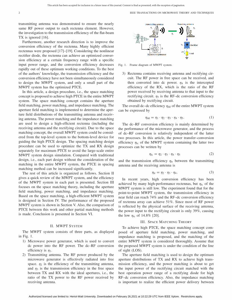
The MWPT system consists of three parts, as displayedin Fig. 1.
1) Microwave power generator, which is used to convertdc power into the RF power. The dc–RF conversionefficiency is η1.
2) Transmitting antenna. The RF power produced by themicrowave generator is effectively radiated into freespace. η2 is the efficiency of the transmitting antenna,and η3 is the transmission efficiency in the free spacebetween TX and RX with the ideal apertures, i.e., theratio of the TX power to the RF power received byreceiving antenna.
Fig. 1. Frame diagram of MWPT system.
3) Rectenna contains receiving antenna and rectifying cir-cuit. The RF power in free space can be received, andthen converted into dc power. η4 is the interceptedefficiency of the RX, which is the ratio of the RFpower received by receiving antenna to that input to therectifying circuit. η5 is the RF–dc conversion efficiencyobtained by rectifying circuit.
The overall dc–dc efficiency ηdd of the entire MWPT systemcan be expressed by
ηdd = η1 · η2 · η3 · η4 · η5. (1)
The dc–RF conversion efficiency is mainly determined bythe performance of the microwave generator, and the processof dc–RF conversion is relatively independent of the lattertwo processes. In this article, the power transfer–conversionefficiency ηtc of the MWPT system containing the latter twoprocesses can be written by
ηtc = η2 · η3 · η4 · η5 (2)
and the transmission efficiency ηtr between the transmittingantenna and the receiving antenna is
ηtr = η2 · η3 · η4. (3)
In recent years, high conversion efficiency has beenachieved by many high-performance rectennas, but ηtc of theMWPT system is still low. The experiment found that for thepoint-to-point MWPT system, the transmission efficiency innear field can reach 74% and the RF–dc conversion efficiencyof rectenna array can achieve 51%. Since most of RF poweris reflected by the physical surface of the receiving antenna,the power input to the rectifying circuit is only 39%, causingthe low ηtc of 14.8% [20].
III. SPACE MATCHING THEORY
To achieve high PTCE, the space matching concept com-posed of aperture field matching, power matching, andimpedance matching is proposed, and the matching of theentire MWPT system is considered thoroughly. Assume thatthe proposed MWPT system is under the condition of the lineof sight (LOS).
The aperture field matching is used to design the optimumaperture distributions of TX and RX to achieve high trans-mission efficiency, and the power matching is about to getthe input power of the rectifying circuit matched with thebest operation power range of a rectifying diode for highRF–dc conversion efficiency. Also, the impedance matchingis important to realize the efficient power delivery between
Authorized licensed use limited to: Heriot-Watt University. Downloaded on February 26,2021 at 10:22:29 UTC from IEEE Xplore. Restrictions apply.

This article has been accepted for inclusion in a future issue of this journal. Content is final as presented, with the exception of pagination.
LU et al.: SPACE MATCHING FOR HIGHLY EFFICIENT MWPT SYSTEMS: THEORY, PROTOTYPE, AND EXPERIMENTS 3
Fig. 2. Frame diagram of space transmission system. Circular apertures areillustrated.
the receiving antenna and rectifying circuit for minimal powerreflection at the optimized input power level.
A. Aperture Field Matching
To achieve high transmission efficiency in free space η3,the aperture field distribution, including the amplitude and thephase of aperture field, between the TX and RX should bematched.
In 1954, the electromagnetic (EM) reaction between the twoapertures �a, a�� is formulated by Rumsey [21], that is,
�a, a�� =∫
V
[�
E tr(a�) · d
�
J(a) − �
H tr(a�) · d
�
K (a)]
(4)
where �Etr(a�) and�
H tr(a�) are the electric field and the mag-
netic field on the TX aperture, respectively.�
J (a) and�
K (a)are the current density distribution and the magnetic currentdensity distribution on the RX, respectively. V is the volumeof the TX.
Both TX and RX are radiating RF power. The powertransmission efficiency η3 in free space between the two idealapertures (not real-world antennas) can be deduced [7]
η3 =∣∣�a, a��∣∣2
16Pa� Pa(5)
where Pa� and Pa are the radiation power of the TX and theRX.
The power transmission in free space between the twoapertures in the MWPT system is shown in Fig. 2, where theTX A� with the radius of R1 and the RX A with the radius ofR2 are the distance of R0 apart. P � is the center of the TX,and P is an arbitrary point on the RX. The distance betweenthe point P � and P is r , and the main beams of the TX andRX are well aligned. For convenience, �Etr(a�) is supposed tobe the electric field in the y-direction. For the electric field inother direction, the similar conclusion can be made. Hence,the vector expression becomes scalar one.
The transmission efficiency in free space η3 can be writtenby
η3 =∣∣∫
A fa(x, y)dxdy∣∣2
∣∣∣∫A� fa�(x �, y �) e− j kR
R dx �dy �∣∣∣2
λ2∫
A | fa(x, y)|2dxdy∫
A� | fa�(x �, y �)|2dx �dy � (6)
where fa�(x �, y �) and fa(x , y) are the scalar functions ofthe electric field distributions on the TX and RX apertures,respectively. λ is the wavelength in free space. Accordingto the distance between the RX and TX, the transmission
efficiency between the transmitting antenna and receivingantenna ηtr can be divided into the following cases.
1) When the TX and RX are located at the far field (R0 >8R2
1/λ), ηtr follows the rule of Friis equation. That is,
ηtr = η2 · η3 · η4 = Ga� Gaλ2
(4μ R0)2 (7)
where the gain of the transmitting antenna Ga� and thereceiving antenna Ga are [8]
Ga� = Da�η2 = 4μ∣∣∫
A� fa�(x �, y �)dx �dy �∣∣2
λ2∫
A� | fa�(x �, y �)|2dx �dy � η2 (8)
Ga = Daη4 = 4μ∣∣∫
A fa(x, y)dxdy∣∣2
λ2∫
A | fa(x, y)|2dxdyη4 (9)
where Da� is the directivity of the transmitting antenna,and Da is the directivity of the receiving antenna.
2) When the transmitting antenna and receiving antennaare located at the near field (R0 < 8R2
1 /λ), someapproximations should be taken as follows:
R ≤√
(R1 + R2)2 + R20 ≈ R0
k R ≈ k R0 + k[x2+y2+(
x �)2+(y �)2 − 2
(xx �+yy �)]/(2R0).
(10)
The transmission efficiency in free space η3 is (11), as shownat the bottom of the next page. Transform the Cartesiancoordinates to polar coordinates, and (11) becomes [8] (12),as shown at the bottom of the next page. For convenience ofcalculations, make the following transformations:√
k
R0r2 = ν2
√k
R0r1 = ν1. (13)
Hence,
fa�(r1, ϕ1)e− jkr2
1 /2R0 = f (ν1, ϕ1) (14)
fa(r2, ϕ2)e− jkr2
2 /2R0 = g(ν2, ϕ2). (15)
By substituting (13)–(15) into (12), we get
η3 =∣∣∫
A g(ν2, ϕ2)F(ν2, ϕ2)dν2dϕ2
∣∣2∫A� | f (ν1, ϕ1)|2dν1dϕ1
∫A |g(ν2, ϕ2)|2dν2dϕ2
=∣∣∫
A f (ν1, ϕ1)G(ν1, ϕ1)dν1dϕ1
∣∣2∫A� | f (ν1, ϕ1)|2dν1dϕ1
∫A |g(ν2, ϕ2)|2dν2dϕ2
(16)
where F(ν2, ϕ2) and G(ν1, ϕ1) are the Fourier transform off (ν1, ϕ1) and g(ν2, ϕ2), which are written by
G(ν1, ϕ1) = 1
2μ
∫A
g(ν2, ϕ2)ejν2ν1 cos(ϕ−ϕ1)dν2dϕ2
F(ν2, ϕ2) = 1
2μ
∫A�
f (ν1, ϕ1)ejν2ν1 cos(ϕ2−ϕ1)dν1dϕ1. (17)
Then, the transmission efficiency between the transmittingantenna and receiving antenna ηtr can be expressed by
ηtr = η2 · η3 · η4
=∣∣∫
A g(ν2, ϕ2)F(ν2, ϕ2)dν2dϕ2
∣∣2∫A� | f (ν1, ϕ1)|2dν1dϕ1
∫A |g(ν2, ϕ2)|2dν2dϕ2
· ηa� · ηa
(18)
Authorized licensed use limited to: Heriot-Watt University. Downloaded on February 26,2021 at 10:22:29 UTC from IEEE Xplore. Restrictions apply.

This article has been accepted for inclusion in a future issue of this journal. Content is final as presented, with the exception of pagination.
4 IEEE TRANSACTIONS ON MICROWAVE THEORY AND TECHNIQUES
where η2 and η4 represent the antenna radiation efficiencyof the transmitting antenna ηa� and that of the receivingantenna ηa.
Cauchy–Schwarz’s inequality yields immediately, i.e.,
ηtr ≤ η1 and ηtr ≤ η2 (19)
where
η1 =∫
A |F(ν2, ϕ2)|2dν2dϕ2∫A� | f (ν1, ϕ1)|2dν1dϕ1
, η2 =∫
A� |G(ν1, ϕ1)|2dν1dϕ1∫A |g(ν2, ϕ2)|2dν2dϕ2
.
By using the Cauchy–Schwarz inequality, when the fieldaperture field distributions of the RX and TX are of conjugatedmatching, we have [8]
g(ν2, ϕ2) = c4 · F∗(ν2, ϕ2) (c4 is a constant)
or
f (ν1, ϕ1) = c5 · G∗(ν1, ϕ1) (c5 is a constant). (20)
The maximum transmission efficiency can be found.For maximum transmission efficiency, the antennas in the
far field can be characterized through the far-field radia-tion pattern of antennas, i.e., antenna gain and half-powerbeamwidth. The transmission efficiency can be acquired basedon Friis equation, which is the traditional design method ofthe far-field point-to-point MWPT system, while at near field,the aperture field distribution of antennas will need to beconsidered.
B. Power Matching
The rectenna, which receives RF power and then convertsit into dc power, is used as an RX in the MWPT system.The rectenna consists of a receiving antenna, an input filter,a rectifier topology, an output filter, matching circuits, and aload, as shown in Fig. 3.
To enhance the power receiving capability, the rectennaarray is used. Two rectenna array configurations, which aredc combining and RF combining, are arranged in arrays toenhance the output dc power. The dc combining configurationsrectify the received RF power of each receiving antennaelement prior to combining it at the dc output, while theRF combining combines the RF power of each receivingantenna element to a single rectifier. Compared with RFcombining, dc combining with no RF power dividers per-forms higher conversion efficiency for a large-scale rectennaarray [22].
For a rectenna, the performance of the rectifying diodelargely determines its conversion efficiency. To achieve high
Fig. 3. Components of the rectenna. The rectifier topology with a nonlineardiode is used to convert RF power received by the antenna into dc power.The input filter is introduced to suppress the high-order harmonics, cooperatedwith the output filter. The matching circuits consist of several microstrip linesthat are inserted between the receiving antenna and the rectifying circuit toachieve good impedance matching for high conversion efficiency.
Fig. 4. Conversion efficiency of the rectifier diode η(Pdiode).
conversion efficiency, the rectifier diodes with small junc-tion capacitance (C j) and small junction resistance (R j ) arechosen. Different rectifier diodes have different best workingpower areas. For example, for an extremely low input powerlevel (∼μW), the spin diodes can be adopted, and for low inputpower level (∼mW), Schottky diodes are mostly used [23],[24]. For high input power level (∼W), the transistor diodeswith high power capability can be selected [25], [26]. Sinceall the rectifier diodes are the nonlinear devices (C j andR j changes with input powers), the conversion efficiencychanges with different input powers, as displayed in Fig. 4,where a maximum conversion efficiency can be achieved atan optimum input power. The RF–dc conversion efficiencyη5 is a function of input power, which can be expressedby
η5 = η(Pin) = η(Pdiode) · [1 − |�(Pin, Pdiode)|2
](21)
where η(Pdiode) is the conversion efficiency of rectifier diodeitself under an optimized power at a certain frequency, and� is the reflection coefficient. On the condition that the inputpower of rectifying circuit Pin is equal to the optimized powerof rectifier diode Pdiode(Pin = Pdiode), the power matching canbe fulfilled for high conversion efficiency. Thus, an appropriaterectifier diode would be chosen according to the interceptedpower of the antenna.
η3 =∣∣∣∫A fa(x, y)dxdy
∫A fa�(x, y)e− jk[x2+y2+(x)2+(y)2−2(xx�+yy2)]/2R0 dx �dy �
∣∣∣2
λ2 R20
∫A| fa(x, y)|2dxdy
∫ | fa�(x, y)|2dx �dy � (11)
η3 =∣∣∣∫A fa(r2, ϕ2)dr2dϕ2
∫A fa(r1, ϕ1)e− jk[r2
1 +r22 −2r1r2 cos(q1−ϕ2)]/2R0 dr1dϕ1
∣∣∣λ2 R2
0
∫ | fa(r2, ϕ2)|2dr2dϕ2∫ | fa�(r1, ϕ1)|2dr1dϕ1
(12)
Authorized licensed use limited to: Heriot-Watt University. Downloaded on February 26,2021 at 10:22:29 UTC from IEEE Xplore. Restrictions apply.

This article has been accepted for inclusion in a future issue of this journal. Content is final as presented, with the exception of pagination.
LU et al.: SPACE MATCHING FOR HIGHLY EFFICIENT MWPT SYSTEMS: THEORY, PROTOTYPE, AND EXPERIMENTS 5
C. Impedance Matching
When the rectifier diode reaches the optimum workingpower, the impedance of the rectifying circuit may showgreatly different from the standard port impedance of 50 .In traditional rectenna designs, by using several matchingstructures, both the antenna and the rectifying circuit aredesigned to match with 50 , separately. But those matchingnetworks would increase the insertion loss. To reduce theinsertion loss, the antenna and the rectifying circuit should beco-designed. On the premise of power matching, the antennaimpedance and the rectifying circuit impedance should reachthe conjugate matching for high conversion efficiency, but notnecessarily matched to 50 . Also, the RF–dc conversionefficiency η5 can be expressed by
η5 = η(Pdiode) ·[1 − ∣∣�(
Z in, Z∗s
)∣∣2]∣∣∣
Pin=Pdiode
(22)
where Z in is the input impedance of the rectifying circuit, andZs is the output impedance of the antenna. For high RF–dcconversion efficiency, the antenna impedance and rectifyingcircuit impedance should achieve conjugate match Z in = Z∗
sat an optimum input power.
D. Power Transfer and Conversion Efficiency
Based on the space matching concept, i.e., aperture fieldmatching, power matching, and impedance matching, ηtc ofthe MWPT system is
ηtc =∣∣∫
A g(ν2, ϕ2)F(ν2, ϕ2)dν2dϕ2
∣∣2∫A� | f (ν1, ϕ1)|2dν1dϕ1
∫A |g(ν2, ϕ2)|2dν2dϕ2
· ηa� · ηa · η(Pdiode) · [1 − |�(Pin, Pdiode)|2]
·[1 − ∣∣�(
Z in, Z∗s
)∣∣2]
(23)
where Pin is the input power of rectifying circuit, which isa function of the aperture field distribution of the receivingantenna g(ν2, ϕ2). Equation (23) becomes
ηtc =∣∣∫
A g(ν2, ϕ2)F(ν2, ϕ2)dν2dϕ2
∣∣2∫A� | f (ν1, ϕ1)|2dν1dϕ1
∫A |g(ν2, ϕ2)|2dν2dϕ2
· ηa · ηa� · η(Pdiode)
·[
1 −∣∣∣∣�
(∫A
g2(ν2, ϕ2)dν2dϕ2/η0, N · Pdiode
)∣∣∣∣2]
·[1 − ∣∣�(
Z in, Z∗s
)∣∣2]
(24)
where η0 is the wave impedance in free space. N is the numberof the rectifying circuit, assuming the rectifying circuit is thesame in the rectenna array.
With the space matching concept, the field distribution ofTX and RX can be optimized for high transmission efficiency,and the reflections caused by the impedance mismatch atan optimum input power are minimum, and so high ηtc canbe achieved. Accordingly, the optimized aperture fields ofthe receiving antenna and transmitting antenna can be usedto guide the antenna design [27], and the receiving antennaelements would be arranged to achieve the best operatingpower range for the rectifier. Then, the rectifying circuit with
Fig. 5. MWPT system model.
the matching stubs can be designed for conjugate impedancematching.
IV. MWPT SYSTEM DESIGN EXAMPLE
To achieve high PTCE for high-power MWPT system,massive TX and RX antenna arrays are necessary for highpower transmission capability. To reduce atmospheric loss andbeam diffraction, the TX and RX are co-located in the nearfield to achieve high transmission efficiency. The proposeddesign procedure with space matching theory can also beextended to far-field MWPT system. In this work, the radiativenear-field MWPT system (0.62(D3/λ)1/2 < R0 < 2D2/λ,where D = 2×R1) with high power transmission is taken asexample, as displayed in Fig. 5, where the transmitting antennawith a circular aperture (the radius R1) is used to emit the RFpower, and then the rectenna array with a circular aperture (theradius R2) is located R0 away from the TX. By using aperturefield matching method, the maximum distance of 28.33 cm inthe near field can be implemented for R1 = 4.28 cm andf = 5.8 GHz. For high transmission efficiency in free space,two circular apertures of the antennas and the distance betweenthe two antennas can be estimated by using the parameter τ ,which is related to the transmission efficiency, as expressedby [28]
τ =√
SA · SA�
λR0(25)
where R0 is the distance between the TX and the RX. SA andSA� are the size of the TX and the RX, i.e., SA = μ R2
1 andSA = μ R2
2 . For high transmission efficiency of 90% (τ =1.6), the detailed parameters of the MWPT system are listedin Table I. To further increase the power transfer distance (upto far-field distance), the size of the TX and RX (antennaeffective aperture) or the operating frequency of the systemwill need to be increased accordingly for maintaining hightransmission efficiency. For example, at the distance of 10 m,the power transmission efficiency will decrease significantlyto 0.025% using the presently proposed TX/RX with a radiusof 4.28 cm/6.12 cm at the operating frequency of 5.8 GHz,while the transmission efficiency could become 90% if weenlarge the radius of TX/RX to 0.33 m/0.73 m at 5.8 GHz.Hereinafter, we have provided Table II to show the relationshipof the aperture size against MWPT distance at given frequencyof 5.8 GHz for the fixed transmission efficiency of 90%.
Authorized licensed use limited to: Heriot-Watt University. Downloaded on February 26,2021 at 10:22:29 UTC from IEEE Xplore. Restrictions apply.

This article has been accepted for inclusion in a future issue of this journal. Content is final as presented, with the exception of pagination.
6 IEEE TRANSACTIONS ON MICROWAVE THEORY AND TECHNIQUES
TABLE I
DETAILED PARAMETERS OF MWPT SYSTEM
TABLE II
APERTURE SIZE AGAINST MWPT DISTANCE
Considering that the power handling capability of the rec-tifying circuit element is milliwatt level, an HSMS 282Crectifier diode is chosen. The conversion efficiency of thenonlinear diode with different input powers at 5.8 GHz fora load of 2200 is shown in Fig. 4, where the highestconversion efficiency η(Pdiode) of 85% can be achieved atthe optimum operation input power Pdiode of 150 mW. It isassumed that the impedance of the antenna and rectifyingcircuit should be well-matched for �(Z in, Z∗
s ) = 0.2, whereabout 96% of power is transmitted and 4% is reflected. Sincethe output dc power can be linearly increased by using multiplerectennas at the RX, compared with a single receiving antenna,using multiple antennas (antenna array) at the RX is beneficialfor obtaining a decent amount of dc output in the MWPTsystem [29]. Thus, the receiving rectenna array with dc com-bining is chosen for highly efficient large-scale array [22]. Therectifying circuits with the number of N are connected to thereceiving antenna array. For the transmitting power Pt of 30 W,the number of the rectifying circuit N = Ptηtr /Pdiode = 180can be estimated for the transmission efficiency of 90% withthe antenna efficiency of 100%.
Based on (24), ηtc is related to the antenna aperture distri-bution, and the optimized aperture field distribution should befound for maximum ηtc.
A. Transmitting Antenna Design
The aperture field distribution (amplitude distribution andphase distribution) of the transmitting antenna can be decom-posed into the real part and the imaginary part, which can bepresented by [30]
f A�(x �, y �) = f A�r
(x �, y �) + j f A�i
(x �, y �) (26)
where the real part f A�r (x �, y �) and the imaginary partf A�i (x �, y �) are described as the polynomial series of x � andy �, which can be expressed by
f A�r(x �, y �) =
S∑s=0
s∑t=0
ast(x �)t(
y �)s−t(27)
f A�i(x �, y �) =
P∑p=0
p∑q=0
bpq(x �)q(
y �)p−q. (28)
Fig. 6. Aperture field distribution of the transmitting antenna. (a) Aperturefield profiles. (b) Simulated magnitude distribution map. (c) Simulated phasedistribution map.
Coefficients ast and bpq can be searched for the maximumvalue of ηtc [29]. For transmitting the power of 30 W, the opti-mum aperture field distribution of the transmitting antennacan be found in Fig. 6. It can be seen that the electric fieldprofile on the transmitting aperture decreases with the radiusof antenna, and the maximum power is located at the antennaboresight.
To achieve the desired aperture field distribution, the trans-mitting antenna can be designed based on the radial lineslot array (RLSA), which is composed of the parallel platewaveguide (PPW) with slot array on its top surface. By usingholographic algorithm method [31], the equivalent aperturemagnetic current distribution corresponding to the aperturefield distribution f A�(ν1) can be found
M0(ν1) = f A�(ν1)ν̂ (29)
where ν1 = (x �2 + y �2)1/2. Due to ϕ-invariance, the currentdistribution is a function of ν1. Then, the current distributioncan be synthesized by placing and sizing the slots of theRLSA [31], [32]. A variation in slot length mainly affectsthe associated magnetic moment magnitude, but the phaseis almost unchanged. Similarly, a variation in slot positionmainly affects the associated magnetic moment phase, but themagnitude remains almost the same. Such a quasi-orthogonallyproperty presents independent actions on the two variables(i.e., the slot lengths and positions) to determine the slot layoutof RLSA. Hence, the position of the slots is arranged optimallyto achieve the matching between the phase distribution onthe RLSA aperture and the target one, while the length of
Authorized licensed use limited to: Heriot-Watt University. Downloaded on February 26,2021 at 10:22:29 UTC from IEEE Xplore. Restrictions apply.

This article has been accepted for inclusion in a future issue of this journal. Content is final as presented, with the exception of pagination.
LU et al.: SPACE MATCHING FOR HIGHLY EFFICIENT MWPT SYSTEMS: THEORY, PROTOTYPE, AND EXPERIMENTS 7
the slots is controlled to ensure the target aperture magnitudedistribution.
The aperture field distribution of RLSA was simulated byusing HFSS as depicted in Fig. 6, where the aperture fielddistribution generated by RLSA agrees well with the targetfield distribution. It can be seen that the magnitude and phaseof the electric field change with the radius of the circular map.The electric field magnitude decreases from the center, and thephase has a strong fluctuation with the radius.
B. Receiving Antenna Design
According to (20), the field distribution on the rectennacan be obtained, and accordingly the power density σ(ν2,ϕ2) = g2(ν2, ϕ2)/η0 on the receiving antenna aperture can bedisplayed in Fig. 7(a), where the power density is a functionof only the radial radius ν2 due to ϕ-invariance. It can be seenthat the power density at the center of the rectenna is largest.As the distance from the antenna center increases, the powerdensity decreases.
Due to the nonlinear rectifier, the performance of therectifier would deteriorate at the power levels that are higheror lower than the optimum input power Pdiode, as displayedin Fig. 4. For high conversion efficiency of rectifying circuit,the receiving antenna array should be reasonably arranged toachieve Pdiode of 150 mW (21.76 dBm) in each rectifyingcircuit unit. Different from the traditional rectenna array,the nonuniform rectenna array consisting of the rectennaelements/rectenna subarray with different sizes in differentzones is proposed, as displayed in Fig. 8. In each zone,the receiving antennas composed of the rectangle subarray (therectangle patches with feeding microstrip lines) are printed onthe F4B substrate (relative permittivity εr = 2.65, thicknessh = 1 mm).
The rectenna subarray in each zone has the same size Si tosatisfy the input power Pdiode, as expressed by
σ(ν2) × Si = Pdiode (30)
where σ(ν2) is the power density on the rectenna array, whichis related to the radial radius ν2 [see Fig. 7(a)]. Since the sizeof receiving antenna elements is much smaller than the largerectenna array, the equal amplitude with in-phase distributionis considered on the small rectenna patch. The rectenna arraycan be divided into four zones (i = 1, 2, 3, 4). In the firstzone (0 ≤ ν2 < 1 cm), the receiving power density dropsto 50%. In the second zone (1 ≤ ν2 < 2.7 cm), the powerdensity is reduced from 50% to 25%. When the power densitydecreases to 8%, the region (2.7 ≤ ν2 < 4 cm) is defined asthe third zone, and the rest is set as the fourth zone, wherein 5.3 ≤ ν2 < 6.12 cm, the power density is close to 0,and no rectenna subarray is deployed. According to the powerdensity distribution of the receiving antenna [see Fig. 7(a)],the arrangement of the rectenna including the number and thesize of the subarray in the four zones can be calculated by
2μ
∫ νi
νi−1
σ(ν2)ν2dν2 = Ni · Pdiode (31)
where νi−1 and νi are the lower boundary and the upperboundary of Zone i , respectively. Ni is the number of the sub-
Fig. 7. Aperture distribution on the rectenna (R0 = 10 cm). (a) Theoreticalpower density distribution. (b) Theoretical phase distribution. (c) Simulatedelectric field magnitude distribution. (d) Simulated electric field phase distri-bution.
TABLE III
RECTENNA ARRAY ARRANGEMENT
array in Zone i . Considering the rectifying circuit arrangement,the subarray Si should be larger than the placement region ofthe rectifying circuit. Since the receiving antenna is a circu-lar aperture, the edge processing for the rectangle rectennasubarray is implemented at the border of two zones. Thearrangement of the nonuniform rectenna is listed in Table III.It can be seen that the nonuniform rectenna is realized, wherelarge subarray is arranged in the low power density area tosatisfy the optimum input power Pdiode [see (30)]. In the firstzone, where the power density is high, a small size of thesubarray is required to intercept the incoming wave power forPdiode. As the radial radius ν2 increases, the power densitydecreases but the subarray size increases for more incomingwave power. It is worth noting that in the second zone, wherethe power density profile has a fairly flat region with almostconstant σ of 0.9 W/cm2, the number of the subarray is largest.In the fourth zone, since the power density falls to nearly 0W/cm2 in 5.3 ≤ ν < 6.12 cm, the subarray is distributed atthe rim of 5.3 cm.
By deploying power dividers with different phase-shiftinglines in each zone (see in Fig. 8), the desired phases canbe achieved for the target conjugated phase distribution. The
Authorized licensed use limited to: Heriot-Watt University. Downloaded on February 26,2021 at 10:22:29 UTC from IEEE Xplore. Restrictions apply.

This article has been accepted for inclusion in a future issue of this journal. Content is final as presented, with the exception of pagination.
8 IEEE TRANSACTIONS ON MICROWAVE THEORY AND TECHNIQUES
Fig. 8. Nonuniform rectenna array.
TABLE IV
IMPEDANCE OF RECTIFYING CIRCUIT AND ANTENNA
IMPEDANCE IN FOUR ZONES
simulated field distribution is also shown in Fig. 7(c) and (d),which basically agrees with the theoretical one [see Fig. 7(a)and (b)]. It can be observed that the simulated electrical fieldmagnitude on the nonuniform RX reaches to its maximumvalue in the center and decreases against the incremental ofthe radius. But in 1–2.7 cm, the electrical field firstly increases,and then reduces as the radius is increased further. Besides,the phase of RX roughly increases from the negative to positivewith the radius.
C. Rectifying Circuit Design
The output impedances of the subarray in the four zonesare listed in Table IV, where the impedances are differentin each zone. Due to use of nonlinear elements (rectifierdiode), the impedance would change as a function of the inputpower, in which the impedance at the optimum input powerPdiode of 150 mW is (31.5 + j3.7) (without matchingstub curve, see Fig. 9), which makes a deviation from theantenna impedance, as displayed in Table IV. To achieve theconjugate matching, some matching stubs are inserted betweenthe antenna and the rectifying circuit, as displayed in Fig. 10,where the circuit is printed on the identical F4B substrateof the receiving antenna (relative permittivity εr = 2.65,thickness h = 1 mm). In the rectifying circuit, a 47-pFseries precapacitor protects the receiving antenna from thereversely rectified dc current. In addition, the precapacitorcooperating with the input matching network is also usedas the input filters of the rectifying circuit. A SchottkyHSMS-282C rectifier diode with a breakdown voltage Vbr
Fig. 9. Rectifying circuit impedance with different input power. (Take theimpedance with matching stubs in the fourth zone as an example.)
Fig. 10. Rectifying circuit with matching stubs in the four zones andconversion efficiency of the four rectifying circuits. (a = 42 mm, b = 16 mm).(a) In the first zone (l1 = 3.2 mm, l2 = 7.1 mm, l3 = 16.6 mm, l4 = 12.8 mm,w1 = 3.4 mm, w2 = 3 mm). (b) In the second zone (l1 = 3.8 mm,l2 = 7.5 mm, l3 = 16.9 mm, l4 = 11.8 mm, w1 = 3.4 mm, w2 = 3 mm).(c) In the third zone (l1 = 2.5 mm, l2 = 9.2 mm, l3 = 14.6 mm,l4 = 12.5 mm, w1 = 3.2 mm, w2 = 2.8 mm). (d) In the fourth zone(l1 = 9.5 mm, l2 = 9.2 mm, l3 = 14.4 mm, l4 = 12.8 mm, w1 = 5.5 mm,w2 = 2.6 mm). (e) Conversion efficiency.
of 15 V, a built-in voltage Vbi of 0.34 V, a series resistance Rs
of 6 , and a junction capacitance C j0 of 0.7 pF is insertedin series to the circuit. A 100-pF bypass capacitor and aload resistor of 2200 are used, which acted as the outputdc filter. It not only smoothens the output voltage but alsosuppresses the high-order harmonics in cooperation with theprecapacitor. Furthermore, two matching circuits, including aninput matching and an output matching circuits, are insertedbetween the antenna and the rectifying circuit, to achieve goodimpedance matching between the antenna in each zone and thecorresponding rectifying circuit. The input matching circuitcontains some microstrip stubs, and the dc output matchingcircuit consists of a stepped-impedance matching microstripline and a 1/4λ microstrip line. To achieve good matching(transform Z0 to Zl3), the impedance can be expressed as [33]
Z(z) = Z0eαz, 0 < z < l3 (32)
Authorized licensed use limited to: Heriot-Watt University. Downloaded on February 26,2021 at 10:22:29 UTC from IEEE Xplore. Restrictions apply.
This article has been accepted for inclusion in a future issue of this journal. Content is final as presented, with the exception of pagination.
LU et al.: SPACE MATCHING FOR HIGHLY EFFICIENT MWPT SYSTEMS: THEORY, PROTOTYPE, AND EXPERIMENTS 9
where at z = 0, z(0) = Z0, at z = l3, z(L) = Zl3 = Z0eαl3,and α is the exponential constant.
The length of the tapered line is determined by minimizingthe reflection coefficient, |�(L)| ≤ 0.1.
The magnitude of �(L) can be expressed by
|�(L)| = 1
2
∣∣∣∣ln Zl3
Z0
∣∣∣∣ sin βL
βL. (33)
In this design, Z0 = 56 and ZL = 38 are used in thefirst zone as an example, and βL has to be greater than 0.6μto have |�(L)| less than 0.1. Therefore, L is determined to be5/16λ for βL = 0.625μ at the frequency of 5.8 GHz. Then, theappropriate width of the stepped-matching microstrip line (thefactor α) is optimized according to (32) for good impedancematching [33]. Subsequently, a 1/4λ microwave line is used toconnect the stepped-impedance line and the load to suppressthe even-order harmonics [3].
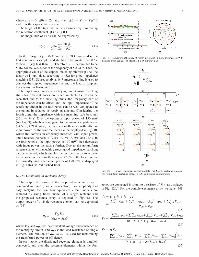
The input impedances of rectifying circuit using matchingstubs for different zones are listed in Table IV. It can beseen that due to the matching stubs, the imaginary part ofthe impedance can be offset, and the input impedance of therectifying circuit in the four zones can be well conjugated tothe output impedance of receiving antenna. Considering thefourth zone, the impedance with the matching stub becomes(35.1 − j4.8) at the optimum input power of 150 mW(see Fig. 9), which is conjugated to the antenna impedance of(34.5 + j4.2) . Also, the conversion efficiency with differentinput power for the four rectifiers can be displayed in Fig. 10,where the conversion efficiency increases with input power,and it reaches the peak of 77.5%, 77.7%, 77.6%, and 77.4% inthe four zones at the input power of 150 mW, then decreaseswith input power increasing further. Due to the nonuniformrectenna array with matching stubs, good impedance matchingcan be achieved, which enables the rectifier circuit to achievethe average conversion efficiency of 77.6% in the four zones atthe basically same intercepted power of 150 mW, as displayedin Fig. 11(a) (in red dashed line).
D. DC Combining of Rectenna Array
The output dc power of the proposed rectenna array iscombined in shunt (parallel connection). For simplicity andeasy analysis, the nonlinear equivalent circuit models arereplaced by using linear model of a single rectenna andthe proposed rectenna array is depicted in Fig. 12. Theoutput power of a single rectenna element can be expressedas [34]
P0 = V 2D0 RL0
(RD0 + RL0)2 (34)
where VD0 and RD0 are the equivalent voltage and resistance ofthe rectifying circuit, and RL0 is the load resistance of singleelement. The relation of RD0 = RL0 is used for maximizingthe transferred power or efficiency.
In each zone, the distributed rectenna element is parallel-connected, and then the rectenna elements within the four
Fig. 11. Conversion efficiency of rectifying circuit in the four zones. (a) Withdistance from center. (b) Measured 2-D contour map.
Fig. 12. Linear equivalent-circuit models. (a) Single rectenna element.(b) Nonuniform rectenna array. (c) DC combining configuration.
zones are connected in shunt to a resistor of RL2, as displayedin Fig. 12(c). For the complete rectenna array, we have [34]
IP = I1 + I 2 + I3 + I 4
=∑37
n=1 VD1n + ∑93m=1 VD2m + ∑44
p=1 VD3p + ∑6q=1 VD4q
RD0 + RL0
(35)
VP =(∑37
n=1VD1n +∑93m=1VD2m +∑44
p=1VD3p +∑6q=1VD4q
)RL0
(n + m + p + q)(RD0 + RL0)(36)
PP = IPVp
=(∑37
n=1VD1n+∑93m=1VD2m +∑44
p=1VD3p+∑6q=1VD4q
)2RL0
(n + m + p + q)(RD0 + RL0)2 .
(37)
Authorized licensed use limited to: Heriot-Watt University. Downloaded on February 26,2021 at 10:22:29 UTC from IEEE Xplore. Restrictions apply.

This article has been accepted for inclusion in a future issue of this journal. Content is final as presented, with the exception of pagination.
10 IEEE TRANSACTIONS ON MICROWAVE THEORY AND TECHNIQUES
TABLE V
MEASURED DC POWER COMBINATION PERFORMANCE
In each zone, rectenna unit is identical, i.e., in the firstzone, RD11 = · · · = RD1n = RD1, in the second zone,RD21 = · · · = RD2m = RD2, in the third zone, RD31 = · · · =RD3p = RD3, and in the fourth zone, RD41 = · · · = RD4q =RD4. The maximum efficiency can be achieved by choosingRL2 = (n/RD1 + m/RD2 + p/RD3 + q/RD4)− 1, where n, m, p,and q are the rectifier number in the first zone, in the secondzone, in the third zone, and in the fourth zone, respectively.To simplify calculations, here we assume that each rectennaelement is identical to the four zones, as rectifier structure andthe input impedance of rectifier are more or less similar. Therelationship can be simplified as RL2 = RL0/(n + m + p + q)for realizing the maximum efficiency.
The rectenna elements are parallel connected to a combinedresistor RL2 of RL2 = RL0/(n + m + p + q) = 12.2 , whichconsists of two resistors of 10 and 2.2 in series. Basedon (34)–(37), the dc power combining efficiency is calculatedby using the total output dc power divided by the sum of thedc powers from the single rectenna element
ηdc = V 2p /RL2
n P01 + m P02 + pP03 + q P04. (38)
By measuring the output dc voltage (Vp) of the combinedresistor RL2 and the output dc power of a single rectennaelement (P01, P02, P03, and P04 are the output dc power inthe first zone, in the second zone, in the third zone, andin the fourth zone, respectively, and the rectifying circuit isthe same in each zone), the dc power combining efficiencyis given in Table V, where the dc power combining effi-ciency for the whole rectenna array is 92% (about 8% loss)[19.3 W/(0.1163 × 37 + 0.1166 × 93 + 0.1164 × 44 +0.1161 × 6) W].
V. PERFORMANCE OF MWPT SYSTEM
A. Theoretical Verification
Due to the proposed space matching concept, the TX/RXand nonuniform rectenna array can be optimally designed.To verify the correctness of the theory, ηtc can be obtainedthrough the electromagnetic (EM) systematic simulation usingHFSS and verified using the experimental measurement for
Fig. 13. Measurement setup.
which the entire MWPT system with the RLSA transmittingantenna and nonuniform rectenna is modeled and fabricated.In the measurement, the whole system was measured infree space, and the measurement setup is shown in Fig. 13.The power source (modeled WATTSINE) is used to generateRF high power, which is magnified by a built-in amplifier.Then, the amplified RF power is shunted by a Nadar 30-dB directional coupler. One way feeds the power meter ofAV2433 to test the output that ensures the transmitting powerof 30 W, while another way feeds the transmitting antenna.The proposed RLSA is used as transmitting antenna to transmitthe power of 30 W (45 dBm) in free space. The nonuniformrectenna array is placed at the distance of L from the RLSA,and the RF power is received by the nonuniform rectennaarray and converted into dc power in different zones. Thedc power of each rectenna element in parallel is electricallyconnected to a resistor, on which the total voltage of the entiresystem is measured by using the multimeter. The distancebetween RLSA and the rectenna array is 10 cm (1.93λ0). Themeasured aperture distributions of the transmitting antennaand receiving antenna are displayed in Fig. 14, where thepower of transmitting/receiving antenna is mainly concentratedin the center, and the power would be decreased along theradial radius, which agrees with the theoretical and simulatedaperture distribution (see in Figs. 6 and 7). Also, the measuredphase distribution changes with radius, which basically agreeswith the simulated one. The measured phase distribution ofthe TX has undulating change, while the measured phasedistribution of the nonuniform RX varies from negative topositive as a function of the radius. The systematic simulatedand measured conversion efficiency of 75.8% and 74.3% canbe achieved by the rectenna array, as displayed in Fig. 11(a)(in green solid line and in orange dotted line), which are a littlelower than the separate simulation with space matching theory(77.6% in red dashed line). Also, the measured 2-D contourmap for the conversion efficiency of the rectifying circuit isdisplayed in Fig. 11(b). The low conversion efficiency of thesystematic simulation and measurement may be caused by theinteraction of two actual antennas. Since the two antennas areinteracted, some power is reflected on the receiving antenna,and the aperture field distribution is a little different from theoptimum distribution, leading to the decrease of conversionefficiency.
ηtc obtained by the overall systematic simulation and mea-surement is listed in Table VI. Also, the theoretical ηtc calcu-lated from (24) and the separate simulation ηtc based on thespacing matching method is listed in Table VI. It can be seenthat ηtc calculated by numerical simulation is higher than thoseobtained by the EM simulations (overall systematic simulation
Authorized licensed use limited to: Heriot-Watt University. Downloaded on February 26,2021 at 10:22:29 UTC from IEEE Xplore. Restrictions apply.

This article has been accepted for inclusion in a future issue of this journal. Content is final as presented, with the exception of pagination.
LU et al.: SPACE MATCHING FOR HIGHLY EFFICIENT MWPT SYSTEMS: THEORY, PROTOTYPE, AND EXPERIMENTS 11
Fig. 14. Measured electrical field distribution. (a) Amplitude distributionof transmitting antenna. (b) Amplitude distribution of receiving antenna.(c) Phase distribution of transmitting antenna. (d) Phase distribution ofreceiving antenna.
TABLE VI
POWER TRANSFER–CONVERSION EFFICIENCY OF MWPT SYSTEM
and separate simulation) and measurement. It may be causedby the actual impedance matching between the antenna andrectifying circuit made by EM simulations and measurement,which is worse than the numerical one (|�| = 0.2). Althoughthe ηtc discrepancy exists among the three simulations andmeasurement, the proposed MWPT system by using spacematching method can be verified to achieve high ηtc, andthe design validates the correctness of the space matchingmethod.
By using the space matching method, the aperture fielddistribution can be optimized to guide the design of TX andrectenna array separately. The full-wave global optimizationof the complex and large-scale entire MWPT system can beavoided.
B. Influence of Parameter Variations
The distance between antennas and the transmitted powerwould affect the transfer–conversion efficiency in MWPT.After investigation, the simulated and measured efficiencieswith different transmitted power and the distance betweenthe antennas are displayed in Fig. 15, where the powertransfer–conversion efficiency ηtr is sensitive to changes in
Fig. 15. Efficiency with different systematic parameters. (a) With distancebetween the antennas when the transmitted power is 30 W. (b) With differenttransmitted power when the distance between the antenna is 10 cm.
TABLE VII
COMPARISON OF POWER TRANSFER–CONVERSION
EFFICIENCY IN DIFFERENT MWPT SYSTEMS
transmitted power and the distance between the antennas.It can be observed in Fig. 15(a) that when the transmittedpower is constant, the transmission efficiency is inverselyproportional to the distance between antennas, causing thedecrease of the transfer–conversion efficiency. Due to thenonlinear rectifier, the conversion efficiency changes with dif-ferent distances. Notably, the simulated transmission efficiencyis higher than the measurement at 5 cm, but the simulatedconversion efficiency is lower than the measurement, since thereceived power in the measurement is closer to the optimumof the rectifier.
As displayed in Fig. 15(b), when the TX power increases,the transmission efficiency stays the same, since the size,operation frequency, and distance between antennas remainunchanged. However, the conversion efficiency will start todecrease when the received power of the rectenna is not withinits optimum transmitting power of 30 W. Thus, the conversionefficiency is the highest at 30 W; therefore, the transfer–conversion efficiency is also the highest. The farther theTX powers deviate from the optimum region, the lower thetransfer–conversion efficiency is. It is worth noting that whenthe transmitted power is larger than the 30 W, the measuredconversion efficiency is higher than the simulated one, sincethe measured input power is closer to the optimum, but thesimulated transmission efficiency is higher than the measuredone, causing a little higher simulated transfer–conversionefficiency.
C. Different MWPT System Comparison
The comparison of ηtc in different MWPT systems withdifferent aperture distributions and the nonuniform/uniform
Authorized licensed use limited to: Heriot-Watt University. Downloaded on February 26,2021 at 10:22:29 UTC from IEEE Xplore. Restrictions apply.

This article has been accepted for inclusion in a future issue of this journal. Content is final as presented, with the exception of pagination.
12 IEEE TRANSACTIONS ON MICROWAVE THEORY AND TECHNIQUES
rectenna is listed in Table VII, where in Case 1(2), the TXwith equal amplitude and in-phase aperture field distributionand the uniform (nonuniform) rectenna array are implemented.In Case 3, the aperture field of the TX is optimized, and theuniform rectenna array is adopted. From Table VII, it canbe seen that, after using the space matching method, ηtc inthis work is the highest in the four cases. In this design,the transmission efficiency and the conversion efficiency are86.4% and 74.3%, respectively. In Case 1 (traditional MWPTsystem), without the consideration of the matching in eachpart of MWPT system, the transmission efficiency and con-version efficiency are the lowest, which are 82.3% and 54.7%,respectively. Accordingly, ηtc decreases sharply, and it only44.8% in Case 1. In Case 2, the transmission efficiency andconversion efficiency are 84.9% and 70.9%, respectively. Sincethe rectenna elements are reasonably arranged in accordancewith the power density of the RX, more power is interceptedby the rectenna array to achieve the optimum input power ofthe rectifying circuit, and so the conversion efficiency can begreatly improved, compared with the uniform rectenna cases(Cases 1 and 3). For the optimized aperture field distribution(Case 3), the transmission efficiency and conversion efficiencyare 87.5% and 58.3%, respectively. In Case 3, the aperture fielddistribution is optimized, and so the transmission efficiencyis improved. However, the obtained ηtc in Case 3 is a littlelower than that in Case 2. That is because although theoptimal aperture field distribution has a higher transmissionefficiency (Case 3), its conversion efficiency is lower than thatof the nonuniform rectenna array (Case 2). Hence, to achievehigh ηtc, the aperture field distribution would be optimizedto achieve aperture field matching for high transmission effi-ciency, and the rectenna should be nonuniformly deployed inline with the power distribution of receiving antenna to achievepower matching. Also, the conjugate impedance matchingbetween the receiving antenna and rectifying circuit should beachieved for high conversion efficiency. The three parts of thespace matching, i.e., aperture field matching, power matching,and impedance matching, are indispensable for high-efficientMWPT system. Compared with other methods for high systemperformance [35], [36], the system-level matching is associ-ated by using space matching method, and various factors, i.e.,impedance, power, and filed, are comprehensively considered,rather than only impedance [35] or radiation pattern [36].
D. Discussion
In the real environments, the path loss in free space exists,such as atmospheric absorption and scatter [9]. The path losscan be simply estimated using
L loss(d B) = 32.45 + 20 lg f + 20 lg R0 (39)
where f is the operation frequency (unit: MHz) and R0 isthe transmission distance (unit: km). According to the aboveequation, the power received by the RX would decrease byL (dB), and the transmission efficiency becomes
η�tr = ηtrηl = ηtr10−L/10 (40)
where ηl is the efficiency caused by path loss. When thetransmission environment deteriorates, such as atmospheric
turbulence and non-line-of-sight (NLOS), the transmissionefficiency would decrease further. In addition, for multipathand complex propagation environments, wireless channel mod-els and channel estimations can be used here to replace thepath loss formulas, therefore, matching the transfer efficiencyto the realistic conditions [37].
VI. CONCLUSION
In this article, the space matching theory, including the aper-ture field matching, power matching, and impedance matchinghas been proposed to increase PTCE of the MWPT system.The aperture field matching has been used to achieve hightransmission efficiency. Due to the aperture field matching,the aperture field distributions of transmitting and receiv-ing antennas can be optimized to guide the real-worldantenna/antenna array designs for the MWPT system. For highconversion efficiency, the input power of the rectenna shouldbe matched to the optimum working power of the rectifierdiode (i.e., power matching), and the appropriate rectifier diodecan be selected to operate well in the nonlinear operatingcondition, while the rectenna array is nonuniformly arranged.Also, at the optimum input power, the antenna impedance andthat of rectifying circuit can realize the conjugate matchingfor high conversion efficiency, and the output dc power ismaximized.
Due to the space matching method, the MWPT system canbe divided into three parts, i.e., the transmitting antenna, thereceiving antenna, and the rectifying circuit, and these partscan be separately optimized for high ηtc, but the matchingbetween these parts is comprehensively considered. Comparedwith traditional methods without the consideration of thematching in each part of MWPT system and other partialmatching methods, the MWPT system with space matchingmethod can achieve the highest ηtc. Simulated and measuredresults have verified that the space matching method can beused to guide the high-efficient MWPT system design. Theparts of MWPT system including the transmitting antenna,the receiving antenna, and the rectifying circuit can be opti-mized separately, and the systematic optimization for thelarge-scale and complicated MWPT system can be signifi-cantly simplified.
REFERENCES
[1] Y. Huang, N. Shinohara, and T. Mitani, “Impedance matching in wirelesspower transfer,” IEEE Trans. Microw. Theory Techn., vol. 65, no. 2,pp. 582–590, Feb. 2013.
[2] J. Kim, D.-H. Kim, and Y.-J. Park, “Analysis of capacitive impedancematching networks for simultaneous wireless power transfer to multipledevices,” IEEE Trans. Ind. Electron., vol. 62, no. 5, pp. 2807–2813,May 2015.
[3] C. Liu, F. Tan, H. Zhang, and Q. He, “A novel single-diode microwaverectifier with a series band-stop structure,” IEEE Trans. Microw. TheoryTechn., vol. 65, no. 2, pp. 600–606, Feb. 2017.
[4] K. Niotaki, A. Georgiadis, A. Collado, and J. S. Vardakas, “Dual-bandresistance compression networks for improved rectifier performance,”IEEE Trans. Microw. Theory Techn., vol. 62, no. 12, pp. 3512–3521,Dec. 2014.
[5] N. Shinohara, “Power without wires,” IEEE Microw. Mag., vol. 12, no. 7,pp. S64–S73, Dec. 2011.
[6] J. Rahola, “Power waves and conjugate matching,” IEEE Trans. CircuitsSyst. II, Exp. Briefs, vol. 55, no. 1, pp. 92–96, Jan. 2008.
[7] G. Borgiotti, “Maximum power transfer between two planar aperturesin the fresnel zone,” IEEE Trans. Antennas Propag., vol. AP-14, no. 2,pp. 158–163, Mar. 1966.
Authorized licensed use limited to: Heriot-Watt University. Downloaded on February 26,2021 at 10:22:29 UTC from IEEE Xplore. Restrictions apply.

This article has been accepted for inclusion in a future issue of this journal. Content is final as presented, with the exception of pagination.
LU et al.: SPACE MATCHING FOR HIGHLY EFFICIENT MWPT SYSTEMS: THEORY, PROTOTYPE, AND EXPERIMENTS 13
[8] A. Kay, “Near-field gain of aperture antennas,” IRE Trans. AntennasPropag., vol. 8, no. 6, pp. 586–593, Nov. 1960.
[9] G. Goubau and F. Schwering, “Free space beam transmission,” inMicrowave Power Engineering, vol. 1, E. C. Okress, Ed. New York,NY, USA: Academic, 1968, pp. 241–255.
[10] A. K. M. Baki et al., “New and improved method of beam forming withreduced side lobe levels for microwave power transmission,” in Proc.IEEE Int. Conf. Electr. Comput. Eng., Dec. 2008, pp. 773–777.
[11] X. Li, B. Duan, J. Zhou, L. Song, and Y. Zhang, “Planar array synthesisfor optimal microwave power transmission with multiple constraints,”IEEE Antennas Wireless Propag. Lett., vol. 16, pp. 70–73, 2017.
[12] S. A. Schelkunoff, “A mathematical theory of linear arrays,” Bell Syst.Tech. J., vol. 22, no. 1, pp. 80–107, Jan. 1943.
[13] C. L. Dolph, “A current distribution for broadside arrays which optimizesthe relationship between beam width and side-lobe level,” Proc. IRE,vol. 34, no. 6, pp. 335–348, Jun. 1946.
[14] I. P. Ivrissimtzis, M. J. Lancaster, and M. Alford, “Supergain printedarrays of closely spaced dipoles made of thick film high-Tc superconduc-tors,” IEEE Proc. Microw., Antennas Propag., vol. 142, no. 1, pp. 26–34,Feb. 1995.
[15] J. Durnin, J. J. Miceli, Jr., and J. H. Eberly, “Diffraction-free beams,”Phys. Rev. Lett., vol. 58, no. 15, pp. 1499–1501, Apr. 1987.
[16] N. Shinohara and N. Kamiyoshikawa, “Study of flat beam in near-fieldfor beam-type wireless power transfer via microwaves,” in Proc. 11thEur. Conf. Antennas Propag. (EUCAP), Mar. 2017, pp. 780–782.
[17] H. Sun, Z. Zhong, and Y.-X. Guo, “An adaptive reconfigurable rectifierfor wireless power transmission,” IEEE Microw. Wireless Compon. Lett.,vol. 23, no. 9, pp. 492–494, Sep. 2013.
[18] Y.-J. Ren, M. F. Farooqui, and K. Chang, “A compact dual-frequencyrectifying antenna with high-orders harmonic-rejection,” IEEE Trans.Antennas Propag., vol. 55, no. 7, pp. 2110–2113, Jul. 2007.
[19] P. Lu, X.-S. Yang, J.-L. Li, and B.-Z. Wang, “Polarization reconfigurablebroadband rectenna with tunable matching network for microwavepower transmission,” IEEE Trans. Antennas Propag., vol. 64, no. 3,pp. 1136–1141, Mar. 2016.
[20] N. Shimokura, N. Kaya, M. Shinohara, and H. Matsumoto, “Point-to-point microwave power transmission experiment,” Electr. Eng. Jpn.,vol. 120, no. 1, pp. 33–39, Jul. 1997.
[21] V. H. Rumsey, “Reaction concept in electromagnetic theory,” Phys. Rev.,vol. 95, no. 6, p. 1705, Sep. 1954.
[22] U. Olgun, C.-C. Chen, and J. L. Volakis, “Investigation of rectennaarray configurations for enhanced RF power harvesting,” IEEE AntennasWireless Propag. Lett., vol. 10, pp. 262–265, 2011.
[23] A. Douyere, J. D. L. S. Luk, and F. Alicalapa, “High efficiencymicrowave rectenna circuit: Modelling and design,” Electron. Lett.,vol. 44, no. 24, pp. 1409–1410, Nov. 2008.
[24] Z. Harouni, L. Cirio, L. Osman, A. Gharsallah, and O. Picon, “A dualcircularly polarized 2.45-GHz rectenna for wireless power transmission,”IEEE Antennas Wireless Propag. Lett., vol. 10, pp. 306–309, 2011.
[25] Y.-H. Suh and K. Chang, “A novel low-cost high-conversion-efficiencymicrowave power detector using GaAs FET,” Microw. Opt. Technol.Lett., vol. 44, no. 1, pp. 29–31, Jan. 2005.
[26] K. Kuroda, R. Ishikawa, and K. Honjo, “Parasitic compensation designtechnique for a C-band GaN HEMT class-F amplifier,” IEEE Trans.Microw. Theory Techn., vol. 58, no. 11, pp. 2741–2750, Nov. 2010.
[27] N. Wang et al., “Aperture field rebuilding in antenna time domainplanar near field measurement,” in Proc. Int. Conf. Microw. Millim. WaveTechnol., Apr. 2008, pp. 1–4.
[28] W. C. Brown, “The technology and application of free-space powertransmission by microwave beam,” Proc. IEEE, vol. 62, no. 1, pp. 11–25,Jan. 1974.
[29] S. Shen and B. Clerckx, “Beamforming optimization for MIMO wire-less power transfer with nonlinear energy harvesting: RF combiningversus DC combining,” IEEE Trans. Wireless Commun., vol. 20, no. 1,pp. 199–213, Jan. 2021.
[30] S. Wan and K. Huang, “Methods for improving the transmission-conversion efficiency from transmitting antenna to rectenna array inmicrowave power transmission,” IEEE Antennas Wireless Propag. Lett.,vol. 17, no. 4, pp. 538–542, Apr. 2018.
[31] J. L. Gómez-Tornero, D. Blanco, E. Rajo-Iglesias, and N. Llombart,“Holographic surface leaky-wave lenses with circularly-polarizedfocused near-fields—Part I: Concept, design, and analysis theory,” IEEETrans. Antennas Propag., vol. 61, no. 7, pp. 3475–3485, Jul. 2013.
[32] M. Ettorre et al., “On the near-field shaping and focusing capability ofa radial line slot array,” IEEE Trans. Antennas Propag., vol. 62, no. 4,pp. 1991–1999, Apr. 2014.
[33] P. Wu et al., “Compact high-efficiency broadband rectifier with multi-stage-transmission-line matching,” IEEE Trans. Circuits Syst. II, Exp.Briefs, vol. 66, no. 8, pp. 1316–1320, Aug. 2019.
[34] Y.-J. Ren and K. Chang, “5.8-GHz circularly polarized dual-dioderectenna and rectenna array for microwave power transmission,” IEEETrans. Microw. Theory Techn., vol. 54, no. 4, pp. 1495–1502, Jun. 2006.
[35] S. Shen and R. D. Murch, “Impedance matching for compact multipleantenna systems in random RF fields,” IEEE Trans. Antennas Propag.,vol. 64, no. 2, pp. 820–825, Feb. 2016.
[36] R. G. Ayestaran, G. Leon, M. R. Pino, and P. Nepa, “Wireless powertransfer through simultaneous near-field focusing and far-field synthe-sis,” IEEE Trans. Antennas Propag., vol. 67, no. 8, pp. 5623–5633,Aug. 2019.
[37] S. Shen, J. Kim, C. Song, and B. Clerckx, “Wireless power trans-fer with distributed antennas: System design, prototype, and experi-ments,” IEEE Trans. Ind. Electron., early access, Nov. 16, 2020, doi:10.1109/TIE.2020.3036238.
Ping Lu (Member, IEEE) received the B.S. degreein electrical engineering and automation from South-west Jiaotong University, Chengdu, China, in 2012,and the Ph.D. degree in radio physics from theUniversity of Electronic Science and Technology,Chengdu, in 2018.
From 2015 to 2017, she was a Joint Ph.D. Stu-dent Scholar with the Laboratoire Ampé re, ÉcoleCentrale de Lyon, INSA de Lyon, Université ClaudeBernard de Lyon, Villeurbanne, France. She is cur-rently an Assistant Professor with the School of
Electronics and Information Engineering, Sichuan University, Chengdu. Hercurrent research interests include rectenna, nondiffraction beams, and wirelesspower transmission.
Kama Huang (Senior Member, IEEE) was born inChongqing, China, in 1964. He received the M.S.and Ph.D. degrees in microwave theory and tech-nology from the University of Electronic Scienceand Technology, Chengdu, China, in 1988 and 1991,respectively.
In 1996, 1997, 1999, and 2001, he was a Vis-iting Scientist with the Scientific Research CenterVidhuk, Kyiv, Ukraine, the Institute of BiophysicsCNR, Genoa, Italy, Technical University Vienna,Vienna, Austria, and Clemson University, Clemson,
SC, USA, where he cooperated with the scientists to study the interactionbetween electromagnetic fields and complex media in biological structure andreaction systems. Since 1994, he has been a Professor with the Department ofRadio and Electronics, Sichuan University, Chengdu, where he has been theDirector since 1997. He has authored or coauthored more than 100 articles. Hiscurrent research interests include microwave chemistry and electromagnetictheory.
Dr. Huang was a recipient of several research awards from the ChineseGovernment.
Yang Yang (Member, IEEE) received the Ph.D.degree in radiophysics from Sichuan University,Chengdu, China, in 2010.
From 2008 to 2010, he was a Visiting Fel-low with Clemson University, Clemson, SC, USA.He joined the Oak Ridge National Laboratory, OakRidge, TN, USA, in 2010, as a Visiting Scholar.He is currently an Associate Professor with theCollege of Electronics and Information Engineering,Sichuan University. His current research interestsinclude microwave chemistry and the applicationsof microwave energy.
Authorized licensed use limited to: Heriot-Watt University. Downloaded on February 26,2021 at 10:22:29 UTC from IEEE Xplore. Restrictions apply.

This article has been accepted for inclusion in a future issue of this journal. Content is final as presented, with the exception of pagination.
14 IEEE TRANSACTIONS ON MICROWAVE THEORY AND TECHNIQUES
Bing Zhang (Senior Member, IEEE) was bornin Taiyuan, China. He received the B.E. degreefrom the Civil Aviation University of China,Tianjin, China, in 2004, the M.E. degree fromShanxi University, Taiyuan, in 2008, and the Ph.D.degree from Nanyang Technological University, Sin-gapore, in 2012, all in electrical and electronicengineering.
He joined the University of Nice Sophia Antipolis,Nice, France, in May 2012, as a Visiting Scholar,and Telecom Bretagne, Brest, France, in Novem-
ber 2014 and April 2015, as a Visiting Scientist. He was a Post-DoctoralResearcher with the Microwave Electronics Laboratory, Department ofMicrotechnology and Nanoscience, Chalmers University of Technology,Gothenburg, Sweden, from November 2011 to October 2015. He was aResearch Fellow with the Department of Electrical and Computer Engineering,National University of Singapore, Singapore, from 2016 to 2017. He has beena Full Professor with the College of Electronics and Information Engineering,Sichuan University, Chengdu, China, since 2017. His research interests includedesign and co-design of RF passive and active devices, millimeter-wave(mmWave) and THz antennas, packaging of mmWave and THz devices,antenna-in-package, 3-D printing technologies for mmWave and THz appli-cations, and wireless power transfer.
Fei Cheng received the B.S. degree from Xid-ian University, Xi’an, China, in 2009, and thePh.D. degree from the University of Electronic Sci-ence and Technology of China, Chengdu, China,in 2015.
From 2013 to 2015, he was a Visiting Ph.D.Student with the University of Birmingham,Birmingham, U.K. From 2015 to 2017, he was aMicrowave Engineer with Chengdu Jiuzou DfineTechnology Company Ltd., Chengdu. In July 2017,he joined Sichuan University, Chengdu, as an Assis-
tant Professor. His main research interests are microwave wireless powertransmission and microwave components such as rectifier, filter, and antenna.
Chaoyun Song (Member, IEEE) received theB.Eng., M.Sc. (Hons.), and Ph.D. degrees in electri-cal engineering and electronics from the Universityof Liverpool (UoL), Liverpool, U.K., in 2012, 2013,and 2017, respectively.
He was a Postdoctoral Research Associate withUoL, from 2017 to 2020. He is currently anAssistant Professor with the School of Engineeringand Physical Sciences (EPS), Heriot-Watt Univer-sity, Edinburgh, U.K. He has published more than70 articles (including 30 IEEE Transactions) in peer-
reviewed journals and conference proceedings. He holds five U.S., European,and U.K. patents. His current research interests include liquid antennas,material science, wireless energy harvesting, rectifying antennas (rectennas),wireless power transfer, metamaterials and metasurface, and smart sensors forthe Internet of Things.
Dr. Song was a recipient of many international awards such as the winner ofthe IET Present Around the World Competition in 2016, the EW Bright-SparksAward for Top 30 U.K. electronic engineers under age 30 in 2018, andthe BAE Systems Chairman’s Award in 2017 for the innovation of thenext-generation global navigation satellite system antennas. He received theHighly Commended Award from the prestigious IET innovation awards overthree categories—“Energy and Power,” “Emerging Technologies,” and “YoungInnovators” in 2018. He is a regular reviewer for more than 20 internationaljournals including Nature Communications and seven IEEE TRANSACTIONS
and a Guest Editor of Wireless Communications and Mobile Computing.
Authorized licensed use limited to: Heriot-Watt University. Downloaded on February 26,2021 at 10:22:29 UTC from IEEE Xplore. Restrictions apply.


![Untitled-1 [newport.eecs.uci.edu]newport.eecs.uci.edu/rfmems/publications/papers/others/C037.pdfmicrowave design, specifically, microwave impedance matching [4] and antenna design](https://img.pdfslide.net/doc/110x75/5e9ac58659dc026b0672dc64/untitled-1-microwave-design-specifically-microwave-impedance-matching-4.jpg)