Embed Size (px)
Citation preview

Louis M. Handler and Janette C. BrionesGlenn Research Center, Cleveland, Ohio
Dale J. MortensenASRC Aerospace Corporation, Cleveland, Ohio
Richard C. ReinhartGlenn Research Center, Cleveland, Ohio
Space Telecommunications Radio System (STRS) ArchitectureTutorial Part 1—Overview
NASA/TM—2012-217819
December 2012

NASA STI Program . . . in Profi le
Since its founding, NASA has been dedicated to the advancement of aeronautics and space science. The NASA Scientifi c and Technical Information (STI) program plays a key part in helping NASA maintain this important role.
The NASA STI Program operates under the auspices of the Agency Chief Information Offi cer. It collects, organizes, provides for archiving, and disseminates NASA’s STI. The NASA STI program provides access to the NASA Aeronautics and Space Database and its public interface, the NASA Technical Reports Server, thus providing one of the largest collections of aeronautical and space science STI in the world. Results are published in both non-NASA channels and by NASA in the NASA STI Report Series, which includes the following report types: • TECHNICAL PUBLICATION. Reports of
completed research or a major signifi cant phase of research that present the results of NASA programs and include extensive data or theoretical analysis. Includes compilations of signifi cant scientifi c and technical data and information deemed to be of continuing reference value. NASA counterpart of peer-reviewed formal professional papers but has less stringent limitations on manuscript length and extent of graphic presentations.
• TECHNICAL MEMORANDUM. Scientifi c
and technical fi ndings that are preliminary or of specialized interest, e.g., quick release reports, working papers, and bibliographies that contain minimal annotation. Does not contain extensive analysis.
• CONTRACTOR REPORT. Scientifi c and
technical fi ndings by NASA-sponsored contractors and grantees.
• CONFERENCE PUBLICATION. Collected papers from scientifi c and technical conferences, symposia, seminars, or other meetings sponsored or cosponsored by NASA.
• SPECIAL PUBLICATION. Scientifi c,
technical, or historical information from NASA programs, projects, and missions, often concerned with subjects having substantial public interest.
• TECHNICAL TRANSLATION. English-
language translations of foreign scientifi c and technical material pertinent to NASA’s mission.
Specialized services also include creating custom thesauri, building customized databases, organizing and publishing research results.
For more information about the NASA STI program, see the following:
• Access the NASA STI program home page at http://www.sti.nasa.gov
• E-mail your question to [email protected] • Fax your question to the NASA STI
Information Desk at 443–757–5803 • Phone the NASA STI Information Desk at 443–757–5802 • Write to:
STI Information Desk NASA Center for AeroSpace Information 7115 Standard Drive Hanover, MD 21076–1320

Louis M. Handler and Janette C. BrionesGlenn Research Center, Cleveland, Ohio
Dale J. MortensenASRC Aerospace Corporation, Cleveland, Ohio
Richard C. ReinhartGlenn Research Center, Cleveland, Ohio
Space Telecommunications Radio System (STRS) ArchitectureTutorial Part 1—Overview
NASA/TM—2012-217819
December 2012
National Aeronautics andSpace Administration
Glenn Research CenterCleveland, Ohio 44135

Available from
NASA Center for Aerospace Information7115 Standard DriveHanover, MD 21076–1320
National Technical Information Service5301 Shawnee Road
Alexandria, VA 22312
Available electronically at http://www.sti.nasa.gov
Trade names and trademarks are used in this report for identifi cation only. Their usage does not constitute an offi cial endorsement, either expressed or implied, by the National Aeronautics and
Space Administration.
Level of Review: This material has been technically reviewed by technical management.

Space Telecommunications Radio System (STRS) Architecture Tutorial Part 1—Overview
Louis M. Handler and Janette C. Briones
National Aeronautics and Space Administration Glenn Research Center Cleveland, Ohio 44135
Dale J. Mortensen
ASRC Aerospace Corporation Cleveland, Ohio 44135
Richard C. Reinhart
National Aeronautics and Space Administration Glenn Research Center Cleveland, Ohio 44135
Abstract
Space Telecommunications Radio System (STRS) Architecture Standard provides a NASA standard for software-defined radio. STRS is being demonstrated in the Space Communications and Navigation (SCaN) Testbed formerly known as Communications, Navigation and Networking Configurable Testbed (CoNNeCT). Ground station radios communicating the SCaN testbed are also being written to comply with the STRS architecture. The STRS Architecture Tutorial Overview presents a general introduction to the STRS architecture standard developed at the NASA Glenn Research Center (GRC), addresses frequently asked questions, and clarifies methods of implementing the standard. The STRS architecture should be used as a base for many of NASA’s future telecommunications technologies. The presentation will provide a basic understanding of STRS.
NASA/TM—2012-217819 1


National Aeronautics and Space Administration
www.nasa.gov 1
Space Telecommunications Radio System (STRS)
Architecture
Tutorial Part 1 - Overview
Glenn Research CenterNovember 2011
NASA/TM—2012-217819 3

National Aeronautics and Space Administration
www.nasa.gov
STRS Architecture
• STRS Background• STRS Hardware & Software Structure• STRS Infrastructure APIs• STRS Application APIs• STRS Configuration Files• STRS Reference Documents
2
NASA/TM—2012-217819 4

National Aeronautics and Space Administration
www.nasa.gov
STRS Background
3
NASA/TM—2012-217819 5

National Aeronautics and Space Administration
www.nasa.gov
STRS Goals and Objectives
• Applicable to space and ground missions of varying complexity.
• Decrease the development time and cost of deployed capabilities.
• Increase the reliability of deployed radios.• Accommodate advances in technology with minimal
rework.• Adaptable to evolving requirements.• Enable interoperability with existing radio assets.• Leverage existing or developing standards, resources,
and experience.• Maintain vendor independence.• Enable waveform portability between compliant platforms.• Enable cognitive radio concepts.
4
NASA/TM—2012-217819 6

National Aeronautics and Space Administration
www.nasa.gov
STRS Solution: Software-Defined Radio (SDR)
• SDRs are commonplace in commercial and military industries.– accommodates advances in technology– enables cognitive radio concepts
• SDRs allow encapsulation of functionality.– allows multiple vendors to work on different parts of the
radio at once– allows updates to one part not to affect the other parts
of the radio – allows portability
• Software design and implementation processes may be leveraged to lower risk and increase reliability
5
NASA/TM—2012-217819 7

National Aeronautics and Space Administration
www.nasa.gov
STRS Background
• SDRs present unique challenges in space.– Radiation environment– Temperature extremes– Autonomous operation– Size, weight, and power (SWaP) limitations– Timescale of deployments– Lengthy development cycles
• JTRS/SCA and OMG/SWRADIO were investigated– including CORBA was too cumbersome due to SWaP – including an XML parser was too cumbersome due to SWaP – SCA’s XML configuration files were too complex for our needs – Used Platform Independent Model (PIM) as a starting point for
STRS API design• Decided to allow a C language interface to minimize SWaP
6
NASA/TM—2012-217819 8

National Aeronautics and Space Administration
www.nasa.gov
STRS Hardware and Software Structure
7
NASA/TM—2012-217819 9

National Aeronautics and Space Administration
www.nasa.gov
SDR Signal Processing Hardware
8
HW
GPP
• General Purpose Processor (GPP) typically contains and executes the Managing Software enabling Software Defined Radio functionality
• Specialized Hardware contains and executes Application Software (i.e. firmware) enabling higher rate processing within the Software Defined Radio (e.g. FPGA)
NASA/TM—2012-217819 10

National Aeronautics and Space Administration
www.nasa.gov
Waveform Application Decomposition
9
• Low rate waveform application components allocated to processor based signal processor. High level services used to control and monitor application software
•Operating Environment (OE) provides access to processor and specialized hardware for waveform processing
•High rate waveform application components allocated to specialized processing hardware
Waveform Applications & High Level Services
Waveform Component Waveform Component
Operating Environment
HWWaveform decomposition driven by designers, not architecture
NASA/TM—2012-217819 11

National Aeronautics and Space Administration
www.nasa.gov 10
STRS Open ArchitectureWaveform Application API and Hardware Abstraction
●Waveform designers access specified API to access processor and implements radio controls in the GPP
● APIs specified by architecture separate the waveform from the Operating Environment for waveform portability
●Operating Environment provides published interfaces (API) services and hardware abstraction control to waveform
●Hardware Abstraction Layer (HAL) also provides wrapper to help port HDL software among platforms
Waveform Applications & High Level Services
API
HWWaveform Component Waveform Component
Operating Environment
NASA/TM—2012-217819 12

National Aeronautics and Space Administration
www.nasa.gov
• Layer cake model– Waveform applications and high level services are insulated from OE by
APIs– STRS APIs abstract
away many platformdifferences
– POSIX used to reduce APIdevelopment
– OE– Hardware Abstraction
Layer (HAL)
11
STRS Architecture
11
NASA/TM—2012-217819 13

National Aeronautics and Space Administration
www.nasa.gov
STRS Architecture Conformance
Optional
Conformant to STRS Architecture Standard requirements for applications
Conformant to STRS Architecture Standard (STRS and WF APIs)
Compliant to POSIX PSE51 or Subset with Waiver
Documented HAL and HID as required by STRS Architecture Specification
12
NASA/TM—2012-217819 14
National Aeronautics and Space Administration
www.nasa.gov
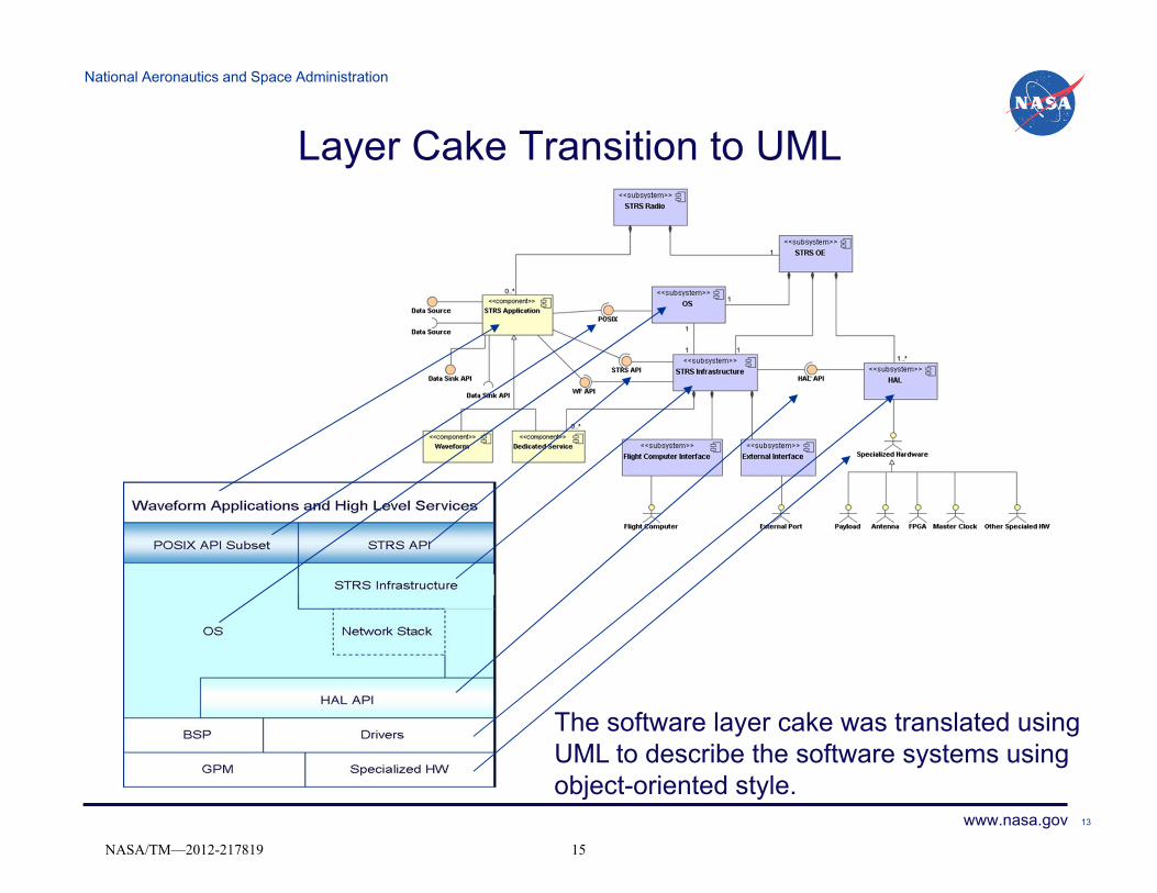
Layer Cake Transition to UML
The software layer cake was translated usingUML to describe the software systems usingobject-oriented style.
13
NASA/TM—2012-217819 15

National Aeronautics and Space Administration
www.nasa.gov
STRS Layered Structure
14
NASA/TM—2012-217819 16

National Aeronautics and Space Administration
www.nasa.gov
STRS Infrastructure APIs
15
NASA/TM—2012-217819 17

National Aeronautics and Space Administration
www.nasa.gov 1616
STRS Infrastructure APIs
• STRS Infrastructure APIs are used:– Waveform calls methods in Infrastructure.– Infrastructure calls appropriate method in another Waveform,
Device, or Infrastructure.
• Purpose:– Methods separate a request from the accomplishment of that
request.– Methods are ‘extern “C”’ so that they can be called from
either C or C++.– Methods insulate waveforms from having to know how
another waveform, device or the infrastructure is implemented.
NASA/TM—2012-217819 18

National Aeronautics and Space Administration
www.nasa.gov 17
STRS Infrastructure APIs
Queue Control• STRS_QueueCreate• STRS_QueueDelete• STRS_Read• STRS_Register• STRS_Log• STRS_Write• STRS_UnregisterDevice Control• STRS_DeviceClose• STRS_DeviceFlush• STRS_DeviceLoad• STRS_DeviceOpen• STRS_DeviceReset• STRS_DeviceStart• STRS_DeviceStop• STRS_DeviceUnload• STRS_SetISRTesting• STRS_RunTest• STRS_GroundTestAttribute• STRS_Configure• STRS_QueryProcess Errors• STRS_GetErrorQueue• STRS_IsOK
• The STRS Software Architecture presents a consistent set of APIs to allow waveform applications, services, and communication equipment to interoperate in meeting a waveform specification
• These APIs are used in general or to control one waveform from another
• The list to the left is the minimum list of APIs that the STRS platform infrastructure must implement
Control• STRS_Initialize• STRS_ReleaseObject• STRS_Start• STRS_StopApplication • STRS_HandleRequest • STRS_InstantiateApp• STRS_AbortAppTime • STRS_GetNanoseconds• STRS_GetSeconds• STRS_GetTimeWarp• STRS_GetTime• STRS_SetTime• STRS_SynchFile (Named Area)• STRS_FileClose• STRS_FileGetFreeSpace• STRS_FileGetSize• STRS_FileOpen• STRS_FileRemove• STRS_FileRename
NASA/TM—2012-217819 19

National Aeronautics and Space Administration
www.nasa.gov
STRS OE Compliance
STRS OE
Static
Dynamic(debug)
Implements STRS_API
DocumentHAL,
Uses HAL API
Uses STRS Application API
HID, etc.
Supports DeviceSupports FileSupports QueueSupports health/fault managementParses configuration files
BITWDT
Supports WF
18
NASA/TM—2012-217819 20

National Aeronautics and Space Administration
www.nasa.gov
STRS Waveform APIs
19
NASA/TM—2012-217819 21
National Aeronautics and Space Administration
www.nasa.gov 20
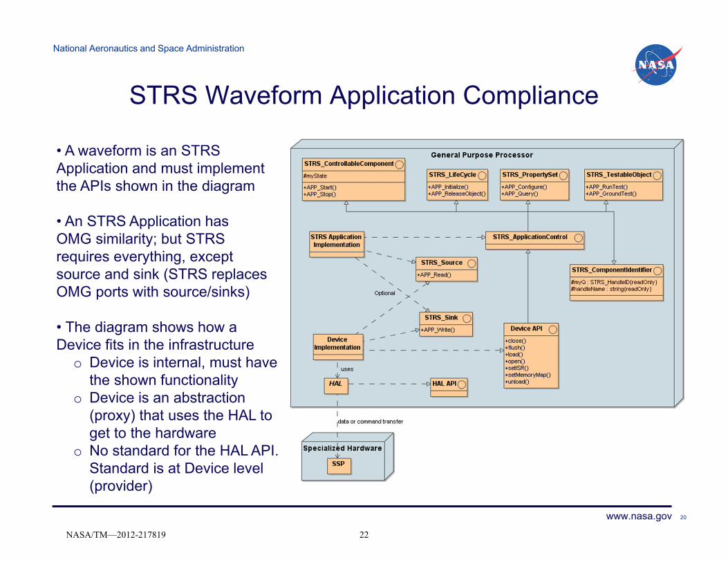
STRS Waveform Application Compliance
• A waveform is an STRS Application and must implement the APIs shown in the diagram
• An STRS Application hasOMG similarity; but STRS requires everything, except source and sink (STRS replaces OMG ports with source/sinks)
• The diagram shows how a Device fits in the infrastructure
o Device is internal, must have the shown functionality
o Device is an abstraction (proxy) that uses the HAL to get to the hardware
o No standard for the HAL API. Standard is at Device level (provider)
NASA/TM—2012-217819 22

National Aeronautics and Space Administration
www.nasa.gov
POSIX Compliance/Conformance
An STRS operating environment can either use an OS that conforms with 1003.13 PSE51 orprovide a POSIX abstraction layer that provides missing PSE51 interfaces. For constrainedresource platforms, the POSIX requirement is based on waveform requirements so that thewaveforms are upward compatible (require POSIX methods).
21
NASA/TM—2012-217819 23

National Aeronautics and Space Administration
www.nasa.gov
STRS Waveform Compliance
STRS WF
Static
Dynamic(debug)
Implements STRS Application API
Document
Uses Configuration Files
Uses STRS Infrastructure API
WF executes (not performance)
WF signal interoperates(not STRS responsibility)
Uses POSIX AEP
22
NASA/TM—2012-217819 24

National Aeronautics and Space Administration
www.nasa.gov
STRS Configuration Files
23
NASA/TM—2012-217819 25

National Aeronautics and Space Administration
www.nasa.gov
Configuration Files
• Require schema and XML as part of the architecture
• The required XML should be transformed to a compact format
• The approach for the transformation is not mandated as part of the architecture
• STRS Reference Implementation uses XSL/XSLT to transform XML to an S-expression as compact form
Schema
XML
Compact Form
Schema is used to validate XML. XML follows Schema.
Transformation Input
Transformation ProcessCompleted XML, schema, and XSL used to create compact form
Tested code in STRS Infrastructure to parse compact form for waveforms
24
NASA/TM—2012-217819 26

National Aeronautics and Space Administration
www.nasa.gov
STRS Reference Documents
25
NASA/TM—2012-217819 27

National Aeronautics and Space Administration
www.nasa.gov
STRS Reference Documents
• Space Telecommunications Radio System (STRS) Architecture Standard Release 1.02.1, December 2010, NASA TM 2010-216809
http://ntrs.nasa.gov/archive/nasa/casi.ntrs.nasa.gov/20110002806_2011001718.pdf
• Space Telecommunications Radio System (STRS) Architecture Goals/Objectives and Level 1 Requirements Document, June 2007, NASA TM 2007-215042.
http://ntrs.nasa.gov/archive/nasa/casi.ntrs.nasa.gov/20080008862_2008008550.pdf
• Space Telecommunications Radio System (STRS) Definitions and Acronyms, May 2008, NASA TM 2008-215445.
http://ntrs.nasa.gov/archive/nasa/casi.ntrs.nasa.gov/20090005977_2009004914.pdf
26
NASA/TM—2012-217819 28

National Aeronautics and Space Administration
www.nasa.gov 27
Backup Slides
NASA/TM—2012-217819 29

National Aeronautics and Space Administration
www.nasa.gov
Waveform State Diagram
28
NASA/TM—2012-217819 30

National Aeronautics and Space Administration
www.nasa.gov
Simplified Diagram
WFSTRS
Infrastructure
STRS APIs
WF APIs
OS
POSIX APIs
29
NASA/TM—2012-217819 31

National Aeronautics and Space Administration
www.nasa.gov
STRS Reference Implementation Development ProcessUse Case Identifier: Example Use Case
Description: A Description of the use case goes here.
External Actors: External actor(s) involved with thisspecific use-case.
Related Use Cases: Use cases that related to this usecase by interaction or similarity.
Precondition: Any precondition that must exist beforethis use case can occur. Usually the initial RADIOstate and WAVEFORM state is listed.Triggering event: Event that triggers use case. Notall use cases have triggering events
Main Flow:1.This will be an ordered list of steps necessary to perform interaction. This is the nominal flow. Alternate flows will be listed below.2.Step 23.Step 34.Step 45.etc.
Resulting event: If completion of use case results inan event it is listed here. Usually the resulting RADIOstate and WAVEFORM state is listed.Post condition: Describe the result of the use caseinteraction. (This is the post condition from thenominal flow)
Alternatives:1a) This is where alternate flows are identified. The alternative will be identified by the number of the main flow where the branch occurs followed by a letter a-z.3a) This is an example of an alternative flow for step 3.3b) This is the second step in the alternative flow for step 3.7a-8a) This is an alternative flow for a range of steps from the main flow.
Comments: Comments on use case.
: STRS Command and Data : Specialized Hardware
: STRS Infrastructure
<<subsystem>>: RTOS
HAL drivers/BSP may be loaded earlier in the sequence
Power On Sequence Diagram
Power On (Boot)1:
Specialized Hardwarestatus
8:
Perform SpecializedHardware BIT
7:
Load and initialize STRS Flight Computer interface
4:
Read Specialized Hardware configurationand install HAL drivers
6: STRS INITIALIZING state5:
STRS READY state9:
Load and initializeSTRS Infrastructure
3:
Perform BIT2:
Refines Requirements
Refines Requirements
Class Diagram
Sequence Diagram
Use Case
+STRS_UploadComplete()
+STRS_StartProcessing()+STRS_StopProcessing()+STRS_FreeResources()
+STRS_UploadRequest()+STRS_InstantiateApp()
+STRS_RemoveApp()
+STRS_GetAttribute()
+STRS_InitComplete()
+STRS_SetAttribute()
+STRS_BuiltInTest()
+STRS_AbortApp()+STRS_Log()
+STRS_Init()
STRS Infrastructure API
Solicited Monitored Item
-parameterName-queueName
-valueList-testType
-delay
+checkParameter()
+isSolicited()
+getDelay()
+deactive()
+isActive()
+activate()
Command and Control Manager
-commandDictionary-allowedTable
+statusMessage()+validate()
+parse()
STRS Application Control API
+WF_StartProcessing()+WF_StopProcessing()
+WF_FreeResources()
+WF_GetAttribute()+WF_SetAttribute()
+WF_BuiltInTest()
+WF_Init()
...
+unregister( publisher, subscriber )+register( publisher, subscriber )
+closeQueue()+openQueue()
+instance()
+notify()
Messaging Manager
-publishSubscribeTable
+STRS_DeviceUnload()+STRS_DeviceReset()
+STRS_DeviceClose()
+STRS_DeviceFlush()+STRS_DeviceOpen()
+STRS_DeviceLoad()
+STRS_DeviceStart()+STRS_DeviceStop()+STRS_GetTime()
+STRS_SetISR()
STRS Device API
Unsolicited Monitored Item
-parameterName-queueName
-valueList-testType
+checkParameter()+deactivate()
+isSolicited()+isActive()
+activate()
Flight Computer Simulator
STRS Messaging API
+STRS_QueueRequest()
+STRS_QueueCreate()+STRS_QueueDelete()
+STRS_Unregister()+STRS_Register()
Security Manager
-keyTable
+authenticateSignature()
+signMessage()+removeKey()
+decrypt()+encrypt()+addKey()
Applications Manager
-configTable-appTable
+parseConfigurationFile()+instance()
Fault Manager
+resetWatchDogTimer()+builtInTest()
STRS Data Source
+STRS_Read()
Memory Manager
+reserve()+release()
STRS Application
STRS Data Sink
+STRS_Write()
UploadControl
+requestUpload()
+getStatistics()
+abortUpload()
+isComplete()
+progress()
Real-Time Clock
+getTime()+synch()
+unload()
+setISR()+close()
+flush()
+load()
Device
-monitorItemList
Health Monitor
+addTest()
+start()+stop()
UploadService
Data Source
+read()
Request
-queueName
-command-source
Data Source
Data Source
Data Source
Data Sink
+write()
Navigation
Data Sink
Data Sink
Data Sink
Extends device. Temporary for testing only.
Messaging API is work in progress
0..*
processes commandsreturns status
notifies
*
1
Data Sink
Data Source
creates0..*
1
0..*1
*
1
30
NASA/TM—2012-217819 32

National Aeronautics and Space Administration
www.nasa.gov
Use Case OverviewSpacecraft
STRS Radio
ControlWaveform
ConfigureWaveform
ManageWaveform
Catalog
Control Radio
AccessWaveform
System Health Manager
<<includes>>Set Waveform ParameterGet Waveform Parameter
<<includes>>Waveform InstantiationWaveform DeallocationStart WaveformStop Waveform
<<includes>>Upload WaveformRemove Waveform
<<includes>> Transmit Receive
<<includes>>Fault Manager
<<includes>>Power OnPower Off
STRS Command and Control
Flight ComputerExternal Port
Payload
Other Space Vehicle
Over the Air User
Ground Station Ground Station<<use>>
A set of use cases were developed which is a set of scenarios that capture the different ways that external users interact with the STRS radio.
31
NASA/TM—2012-217819 33

National Aeronautics and Space Administration
www.nasa.gov
Class Example
Application Manager• The Application Manager is
responsible for the passing of messages or invoking commands in other application objects such as devices, waveforms, or services actively running on the STRS radio.
• It is responsible for creating or aborting application objects, waveforms, or services.
• It is also responsible for parsing the Configuration Files and setting corresponding values in the appropriate classes.
Application Manager
-appTable-configTable
+parseConfigurationFile()+instance()
Name – Name that identifies the class and describes the functionality
Attributes – Variables containing theapplicable data
Methods – Functions that are called to implement some operation
Above is an example of the UML representation of a Class
32
NASA/TM—2012-217819 34

National Aeronautics and Space Administration
www.nasa.gov
STRS Open Architecture Hardware Representation
Data
Clock
Control
Modules
GeneralPurpose
ProcessingModule (GPM)
Specialized Processing
Module (SPM)
RadioFrequency
Module (RFM)
Ground Test
External Connections
Data
Control
Internal Connections
Clock
RadioFunction
System Bus
External Interface
33
NASA/TM—2012-217819 35

National Aeronautics and Space Administration
www.nasa.gov
SDR/STRS Hardware Functional Diagram
texttext
text
Data Formatting
Spacecraft Data
Interface
Clock Distribution
Transmit RFDigital to Analog
General Processing Module (GPM)
General Purpose Processor
Host/TT&CInterface
Ground Test Interface
Low Speed Signal
Processing
Persistent Memory
RF Module (RFM)
Radio Configuration
& System ControlWork Area Memory
High SpeedDigital Signal Processing
Signal Processing Module (SPM)
AntennaInterface
Clock Interface
Analog to Digital Receive RF
Antenna Control
Interface
OperatingEnvironment
Waveform / Application
System Control
Variable Gain/
FrequencyTest & Status
Test & Status
Data Buffer/
Storage Waveform
34
NASA/TM—2012-217819 36

National Aeronautics and Space Administration
www.nasa.gov
SDR/STRS Hardware Functional Diagram
texttext
text
Data Formatting
Spacecraft Data
Interface
Clock Distribution
Transmit RFDigital to Analog
General Processing Module (GPM)
General Purpose Processor
Host/TT&CInterface
Ground Test Interface
Low Speed Signal
Processing
Persistent Memory
RF Module (RFM)
Radio Configuration
& System ControlWork Area Memory
High SpeedDigital Signal Processing
Signal Processing Module (SPM)
AntennaInterface
Clock Interface
Analog to Digital Receive RF
Antenna Control
Interface
OperatingEnvironment
Waveform / Application
System Control
Variable Gain/
FrequencyTest & Status
Test & Status
Data Buffer/
Storage Waveform
General Processing Module –consists of the general purpose processor, appropriate memory, spacecraft bus (e.g. MILSTD-1553) , interconnection bus (e.g. PCI), and the components to support the configuration of the radio.
Signal Processing Module – signal processing used to handle the transformation of digital signals into data packets. Components include ASIC’s, FPGA’s, DSP’s, memory, and connection fabric/bus (e.g. PCI, flex-fabric)
RF Module –handles the RF functionality to transmits/receive the digital signal. Its associated components include RF switches, diplexer, filters, LNAs and power amplifiers. 35
NASA/TM—2012-217819 37

National Aeronautics and Space Administration
www.nasa.gov
texttext
text
Data Formatting
Spacecraft Data
Interface
Clock Distribution
Transmit RFDigital to Analog
General Processing Module (GPM)
General Purpose Processor
Host/TT&CInterface
Ground Test Interface
Low Speed Signal
Processing
Persistent Memory
RF Module (RFM)
Radio Configuration
& System ControlWork Area Memory
High SpeedDigital Signal Processing
Signal Processing Module (SPM)
AntennaInterface
Clock Interface
Analog to Digital Receive RF
Antenna Control
Interface
OperatingEnvironment
Waveform / Application
HAL
System Control
Variable Gain/
FrequencyTest & Status
Test & Status
Data Buffer/Storage
Waveform
API
STRS Hardware Functional Diagram
Module Interfaces abstract and define the module functionality for data flow to waveform components. Enables multiple vendors to provide different modules or add modules to existing radios. Electrical interfaces, connector requirements, and physical requirements are specified/published by the platform provider.
HAL API is published so that specialized HW developed by multiple vendors can be integrated with another vendor’s STRS infrastructure.
Software/Firmware Abstraction: Layers define interfaces between components, separating SW/FW from HW.
APIs separate waveform from operating environment – enabling waveform portability.
Test & Status on each module
Managing Software runs on GPM
36
NASA/TM—2012-217819 38

National Aeronautics and Space Administration
www.nasa.gov
The End
37
NASA/TM—2012-217819 39

REPORT DOCUMENTATION PAGE Form Approved OMB No. 0704-0188
The public reporting burden for this collection of information is estimated to average 1 hour per response, including the time for reviewing instructions, searching existing data sources, gathering and maintaining the data needed, and completing and reviewing the collection of information. Send comments regarding this burden estimate or any other aspect of this collection of information, including suggestions for reducing this burden, to Department of Defense, Washington Headquarters Services, Directorate for Information Operations and Reports (0704-0188), 1215 Jefferson Davis Highway, Suite 1204, Arlington, VA 22202-4302. Respondents should be aware that notwithstanding any other provision of law, no person shall be subject to any penalty for failing to comply with a collection of information if it does not display a currently valid OMB control number. PLEASE DO NOT RETURN YOUR FORM TO THE ABOVE ADDRESS.
1. REPORT DATE (DD-MM-YYYY) 01-12-2012
2. REPORT TYPE Technical Memorandum
3. DATES COVERED (From - To)
4. TITLE AND SUBTITLE Space Telecommunications Radio System (STRS) Architecture Tutorial Part 1--Overview
5a. CONTRACT NUMBER
5b. GRANT NUMBER
5c. PROGRAM ELEMENT NUMBER
6. AUTHOR(S) Handler, Louis, M.; Briones, Janette, C.; Mortensen, Dale, J.; Reinhart, Richard, C.
5d. PROJECT NUMBER
5e. TASK NUMBER
5f. WORK UNIT NUMBER WBS 439432.04.07.01
7. PERFORMING ORGANIZATION NAME(S) AND ADDRESS(ES) National Aeronautics and Space Administration John H. Glenn Research Center at Lewis Field Cleveland, Ohio 44135-3191
8. PERFORMING ORGANIZATION REPORT NUMBER E-18561
9. SPONSORING/MONITORING AGENCY NAME(S) AND ADDRESS(ES) National Aeronautics and Space Administration Washington, DC 20546-0001
10. SPONSORING/MONITOR'S ACRONYM(S) NASA
11. SPONSORING/MONITORING REPORT NUMBER NASA/TM-2012-217819
12. DISTRIBUTION/AVAILABILITY STATEMENT Unclassified-Unlimited Subject Categories: 17 and 61 Available electronically at http://www.sti.nasa.gov This publication is available from the NASA Center for AeroSpace Information, 443-757-5802
13. SUPPLEMENTARY NOTES
14. ABSTRACT Space Telecommunications Radio System (STRS) Architecture Standard provides a NASA standard for software-defined radio. STRS is being demonstrated in the Space Communications and Navigation (SCaN) Testbed formerly known as Communications, Navigation and Networking Configurable Testbed (CoNNeCT). Ground station radios communicating the SCaN testbed are also being written to comply with the STRS architecture. The STRS Architecture Tutorial Overview presents a general introduction to the STRS architecture standard developed at the NASA Glenn Research Center (GRC), addresses frequently asked questions, and clarifies methods of implementing the standard. The STRS architecture should be used as a base for many of NASA’s future telecommunications technologies. The presentation will provide a basic understanding of STRS. 15. SUBJECT TERMS User manuals (computer programming); Architecture (computers); Telecommunications
16. SECURITY CLASSIFICATION OF: 17. LIMITATION OF ABSTRACT UU
18. NUMBER OF PAGES
46
19a. NAME OF RESPONSIBLE PERSON STI Help Desk (email:[email protected])
a. REPORT U
b. ABSTRACT U
c. THIS PAGE U
19b. TELEPHONE NUMBER (include area code) 443-757-5802
Standard Form 298 (Rev. 8-98)Prescribed by ANSI Std. Z39-18