Embed Size (px)
Citation preview
Sadhana, Vol. 22, Part 6, December 1997. pp. 675-688. © Printed in India.
Space vector pulsewidth modulation - A status review
V T RANGANATHAN
Department of Electrical Engineering, Indian Institute of Science, Bangalore 560 012, India e-mail: vtran @ ee.iisc.ernet.in
Abstract. The technique of space vector pulsewidth modulation (SVM) is reviewed. The basic principle of SVM is derived and is compared with sine- triangle PWM. Operation in the overmodulation range is explained. Extension of SVM to other inverter-motor combinations such as three level inverters and split phase motors are discussed.
Keywords. Pulsewidth modulation (PWM); space vectors; space vector mod- ulation (SVM).
1. Introduction
A large number of variable speed induction motor drives are in use today in applications as varied as pumps and fans, traction, machine tool spindles, printing presses etc. The vast majority of them are based on voltage source inverters, although other circuit configurations are possible. This is because the developments in power device technology have resulted in the availability of a number of power switches, such as MOSFET, IGBT and GTO, which meet every kind of power rating, from a few hundred watts to megawatts. Voltage source inverters, as is well known, produce pulsed output waveforms, consisting of the fundamental component which is required to drive the motor, as well as the harmonics which contribute only to the losses and torque pulsations. The method of determining the widths and the sequence of the voltage pulses produced by the inverter is known as Pulsewidth Modulation (PWM).
The basic attempt in all Pulsewidth Modulation techniques is to produce the required amplitude and frequency of the fundamental voltage necessary for driving the motor, while moving the energy in the harmonics to a higher range in the frequency spectrum. The impedance presented by the motor to these harmonic voltages consists mainly of the leakage reactance. The expectation is that at such higher frequencies, even the reac- tance of the machine leakage inductance will be appreciable, thereby limiting the har- monic currents drawn from the inverter. Also, since the torque pulsations created by the harmonic currents will also be at a higher frequency, the motor should be able to run smoothly.
675
676 V T Ranganathan
The constraint on the PWM process is the fact that additional switchings per cycle are required in order to accomplish the modulation. This increases the losses in the inverter. Moreover, as switching patterns become more complicated, an individual inverter phase may be required to produce pulses or notches of very small width. The swiching times of the power devices used in the inverter impose a limitation here.
Several popular PWM techniques have emerged over the years. The earliest one was the sine triangle method (Schonung & Stemmler 1964), in which the switching instants of the inverter legs are decided by the points of intersection of a high frequency (anywhere from 450 hertz to a few kilohertz) triangular wave and a sinewave at the frequency of the required fundamental motor voltage. The triangle is referred to as the carrier and the sine as the reference. The output voltage produced by the inverter contains the funda- mental component, of which the sine wave is a replica. In addition, it contains harmonic components which are located in bands around multiples of the triangle frequency. It is, in general, necessary to synchronise the carrier to the sine wave, in order to avoid frequency components in the output below the sine frequency - so called subharmonic components.
The sine triangle method of PWM, though used widely, has its limitations. The amplitude of the sine wave has to be increased in proportion to its frequency, in order to keep the motor flux constant. Therefore, at higher motor speeds, a situation arises where the amplitude of the sine wave becomes equal to that of the triangle. If the sine wave amplitude were to increase any further, the linearity between the sine and the fundamental component of the inverter output voltage is lost. This situation is referred to as overmodulation. A further consequence of overmodulation is that frequency components with low harmonic numbers (5th, 7th etc.) begin to appear in the output voltage. From the implementation point of view also, sine triangle PWM requires some care. Where the triangle frequency is limited by the switching speed of the power devices, analog realisations give the best results in terms of output waveform quality. However, analog realisations require considerable ingenuity, especially to achieve synchronisation (Kliman & Plunkett 1979; Green & Boys 1982).
Subsequently, other techniques such as Selected Harmonic Elimination (Pollmann 1983), which were more amenable to digital implementation, have also been used widely. Today, the trend being towards standard hardware based on digital processors, it is preferred to implement all PWM techniques through real time software execution of algorithms. A number of software realisations of the sine triangle technique have been reported in the literature. They are good approximations of the analog realisation if the frequency of the triangle is high (at least lkilohertz or above). The limitation of the output voltage due to overmodulation effects is, however, still a factor to be considered.
The above techniques have one thing in common in that the PWM patterns are calcu- lated for each phase, independent of switchings in the other phases. It has subsequently been realised that good results can be obtained if the combined effect of all the three output voltages of the inverter on the motor are taken into account in generating the switching pattems. The conceptual framework for doing so is the space vector modelling of ac motors. In the following sections, the notion of space vectors is introduced and the technique of generating PWM patterns based on these viz. space vector PWM is reviewed.
Space vector pulsewidth modulation - A status review 677
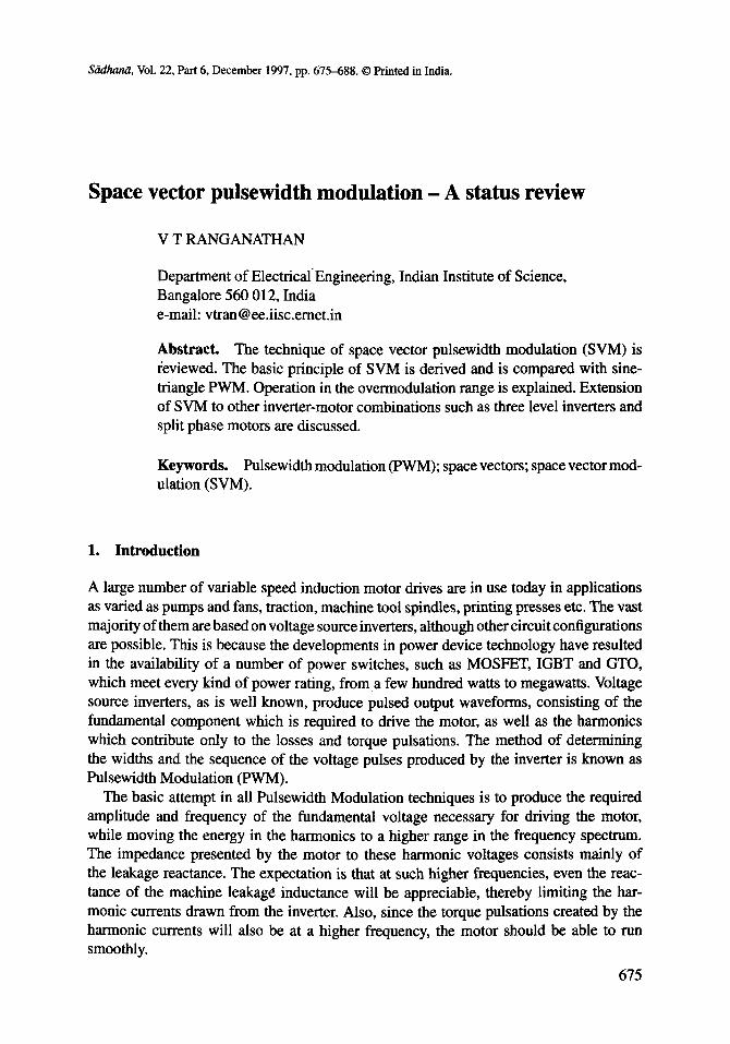
Figure I. Three-phase half-bridge voltage source inverter.
2. Basic space vector PWM (Holtz et al 1987; Van der Broek et al 1988)
2.1 Space vectors
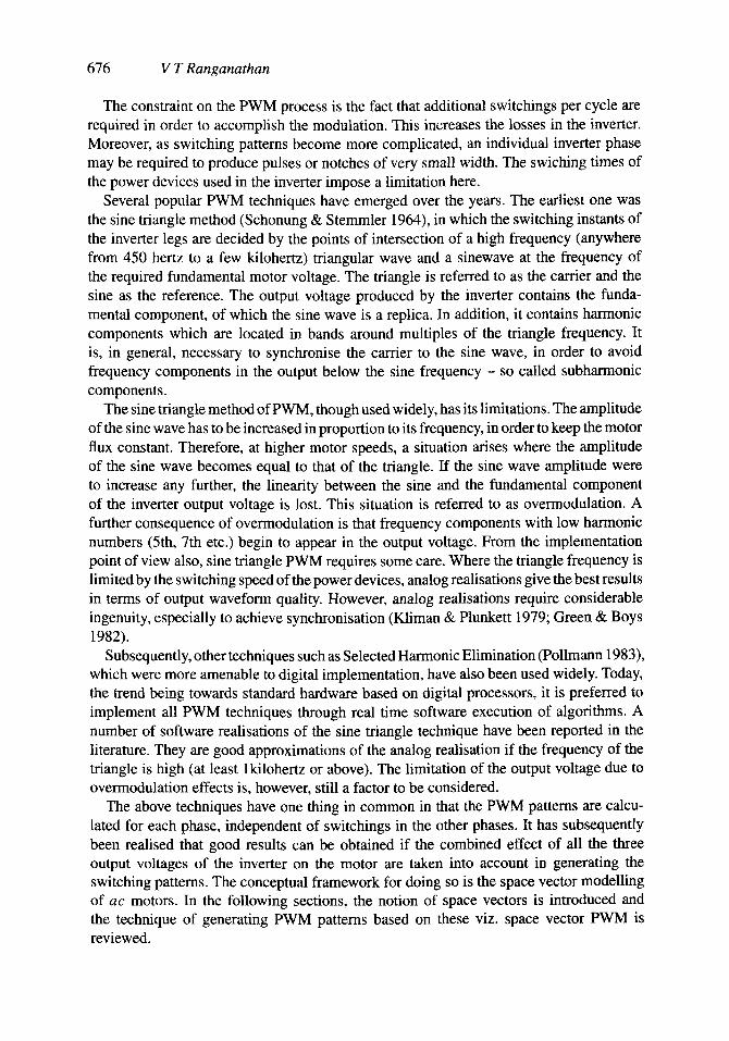
Consider a three-phase half-bridge voltage source inverter, shown in figure 1. Each phase to centre-tap voltage, viz. VRO, Vyo, VBO, can have only two possible values, namely +Vdc/2 or --Vdc/2 respectively. As there are three switches, corresponding to the three phases, there are eight possible states for the inverter at any instant of time. Corresponding to each of the switching states, the motor line to neutral voltages can be determined using the following equations,
Vsl=VRN = (1/3)(VRy -- VBR),
Vsl=(1/3)(2VRo - Vyo -- VBO),
Vs2=(1/3)(2Vyo - VBO -- VRO),
Vs3=(1 /3 ) (2VBo- VRO- Vyo).
From these three-phase voltages, equivalent two-phase voltages are defined as follows,
(1)
Vsa = (3/2)Vsl,
V~b = (V~/2)(V~2 - ½3). (2)
tit tit tit tit ( t ) + - - ( 2 ) + ÷ - ( 3 ) - ÷ - ( 4 ) - * +
tit tit tit tit 151 " " + 161 + - + 171 * + + (81 - - -
Figure 2. inverter.
Eight switching states of the
678 V T Ranganathan
v3 v2
I1~~~ v4 v 4 ~ .
. + + v7 0 . . . -
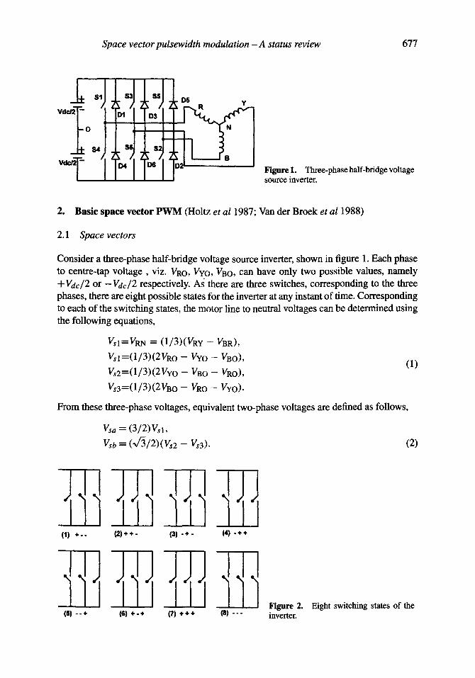
. . + ~lm ~ ÷ . ÷ Figure 3. ing state.
Space vector corresponding to each switch-
The space vector of the machine stator voltage is then defined as
Vs = Vsa + jVsb. (3)
The eight switching states of the inverter and the corresponding space vectors Of the machine stator voltage are shown in figures 2 and 3 respectively.
It can be seen that at any instant of time, there are only eight possible positions for the voltage space vector. When the inverter is operated in the six-step mode, the switching states go through the sequence 1-2-3-4-5-6-1-2-3. The states 0 and 8 are not used at all. The space vector of stator voltage stays in each of the positions 1 to 6 for a time interval corresponding to 60 ° of the fundamental period and jumps to the next position at the end of every sixty degrees (one-sixth of the fundamental period). With above switching sequence, at every jump in the position of the voltage space vector, only one of the three phases of the inverter switches from top to bottom or vice versa.
2.2 Space vector PWM
The ideal trajectory for the voltage space vector is of course a circle described with uniform angular velocity, which results only when the motor is fed from a three-phase sinusoidal voltage source. The objective of any PWM process is therefore to approximate this ideal trajectory of the voltage space vector by switching amongst the eight standard positions. Towards this end, the continuously moving reference vector V* is sampled at a sampling frequency fs. During the interval Ts = 1/fs between samples, the reference vector is assumed to remain constant. It is clear that for this assumption to be valid, the sampling frequncy should be fairly high compared to the fundamental output frequency desired from the inverter.
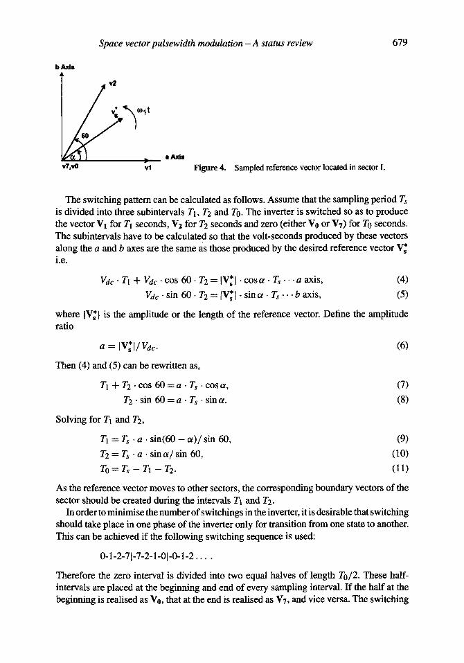
Now consider that at a particular sampling instant, the reference V* is situated in sector I as shown in figure 4. The angle ot represents the position of the reference vector with respect to the beginning of the sector. It is intuitively clear that the reference vector can be reproduced best during the period till the next sample by switching the inverter to create the vectors Vi, V2, V0 and V7 in some sequence. Selecting any of the other vectors would result in a greater deviation of the actual vector from the desired reference and would thus contribute to harmonics.
Space vec tor pu l sew id th modula t ion - A s tatus rev iew 679
b Axis
v2
6O
!= V7,vO v l ~ 4 . Sampled reference vector located in sector I.
The switching pattern can be calculated as follows. Assume that the sampling period Ts
is divided into three subintervals T1, T2 and To. T h e inverter is switched so as to produce the vector V1 for Tl seconds, Vz for T2 seconds and zero (either Vo or VT) for To seconds. The subintervals have to be calculated so that the volt-seconds produced by these vectors along the a and b axes are the same as those produced by the desired reference vector V* i.e.
Vdc" T1 + Vdc" cos 60. T2 = IV,*I" cosot • T s . . . a axis, (4)
Vdc" sin 60- T2 = IV*l- sint~ • Z s . . . b axis, (5)
where IV*I is the amplitude or the length of the reference vector. Define the amplitude ratio
a = IV* l /Vdc .
Then (4) and (5) can be rewritten as,
T1 -t- T2. cos 60 = a • Ts • cos or,
T2. sin 60 = a . Ts • sin or.
Solving for T1 and T2,
/'1 = Ts • a . sin(60 - c0 / s in 60,
1"2 = Ts • a . sin or/sin 60,
T o= Ts - T 1 - T2.
(6)
(7) (8)
(9) (10) (11)
As the reference vector moves to other sectors, the corresponding boundary vectors of the sector should be created during the intervals T1 and T2.
In order to minimise the number of switchings in the inverter, it is desirable that switching should take place in one phase of the inverter only for transition from one state to another. This can be achieved if the following switching sequence is used:
0-1-2-71-7-2-1-01-0-1-2 . . . .
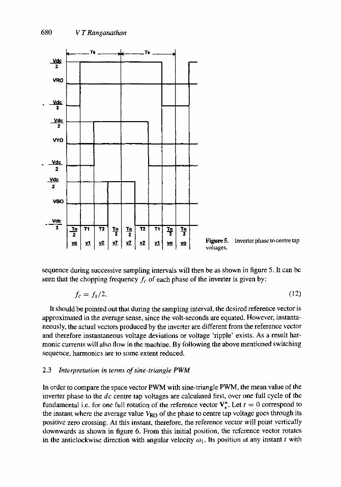
Therefore the zero interval is divided into two equal halves of length To~2. These half- intervals are placed at the beginning and end of every sampling interval. If the half at the beginning is realised as V0, that at the end is realised as VT, and vice versa. The switching
680 V T Ranganathan
Vdc 2
VRO
Ti p . L J
F Vdc
2
Vdc 2
VYO
Vdc 2
2
~BO
Vde
2
Figure 5. voltages.
Inverter phase to centre tap
sequence during successive sampling intervals will then be as shown in figure 5. It can be seen that the chopping frequency fc of each phase of the inverter is given by:
fc = f s /2 . (12)
It should be pointed out that during the sampling interval, the desired reference vector is approximated in the average sense, since the volt-seconds are equated. However, instanta- neously, the actual vectors produced by the inverter are different from the reference vector and therefore instantaneous voltage deviations or voltage 'ripple' exists. As a result har- monic currents will also flow in the machine. By following the above mentioned switching sequence, harmonics are to some extent reduced.
2.3 Interpretation in terms of sine-triangle PWM
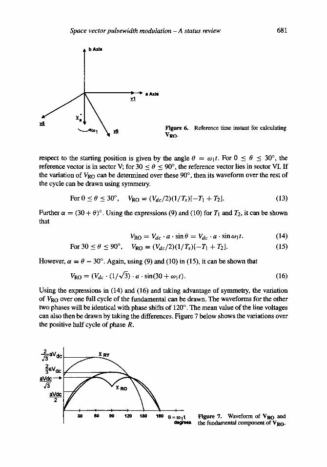
In order to compare the space vector PWM with sine-triangle PWM, the mean value of the inverter phase to the dc centre tap voltages are calculated first, over one full cycle of the fundamental i.e. for one full rotation of the reference vector V*. Let t = 0 correspond to the instant where the average value VRO of the phase to centre tap voltage goes through its positive zero crossing. At this instant, therefore, the reference vector will point vertically downwards as shown in figure 6. From this initial position, the reference vector rotates in the anticlockwise direction with angular velocity o91. Its position at any instant t with
Space vector pulsewidth modulation - A status review 681
b AXIS
• Axis
Figure 6. VRO.
Reference time instant for calculating
respect to the starting position is given by the angle 0 = tOlt. For 0 < 0 < 30 °, the reference vector is in sector V; for 30 < 0 < 90 °, the reference vector lies in sector VI. If the variation of VRO can be determined over these 90 °, then its waveform over the rest of the cycle can be drawn using symmetry.
For0 < 0 < 30 °, VRO = (Vac/2)(1/Ts)[-T1 + T2]. (13)
Further a = (30 + 0) °. Using the expressions (9) and (10) for T1 and T2, it can be shown that
VRO = Vdc • a • sin 0 = V c l c • a • sin to 1 t.
For 30 < 0 < 90 °, VRO = (Vdc/2)(1/Ts)[-TI + T2].
(14)
(15)
However, ot = 0 - 30 °. Again, using (9) and (10) in (15), it can be shown that
VRO = (Vdc. (1/V~) • a . sin(30 + ~Olt). (16)
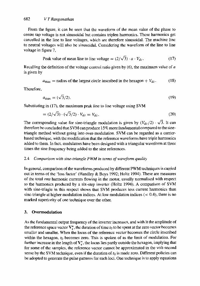
Using the expressions in (14) and (16) and taking advantage of symmetry, the variation of VRO over one full cycle of the fundamental can be drawn. The waveforms for the other two phases will be identical with phase shifts of 120 ° . The mean value of the line voltages can also then be drawn by taking the differences. Figure 7 below shows the variations over the positive half cycle of phase R.
~33 aVdc ~aVdc
aVdc
aVdc 2
-vRy
30 60 90 120 160 180 0 : ~ Figure 7. Waveform of VRO and the fundamental component of VRO.
682 V T Ranganathan
From the figure, it can be seen that the waveform of the mean value of the phase to centre tap voltage is not sinusoidal but contains triplen harmonics. These harmonics get cancelled in the line to line voltages, which are therefore sinusoidal. The machine line to neutral voltages will also be sinusoidal. Considering the waveform of the line to line voltage in figure 7,
Peak value of mean line to line voltage = (2/~/3) • a • V&. (17)
Recalling the definition of the voltage control ratio given by (6), the maximum value of a is given by
amax = radius of the largest circle inscribed in the hexagon + V&. (18)
Therefore,
amax = (~/3/2). (19)
Substituting in (17), the maximum peak line to line voltage using SVM
= (2/~f3). (vc3/2) • V& = Vdo (20)
The corresponding value for sine-triangle modulation is given by (Vdc/2) - "~,/3. It can therefore be concluded that SVM can produce 15 % more fundamental compared to the sine- triangle method without going into over-modulation. SVM can be regarded as a carrier- based technique, with the modification that the reference waveforms have triple harmonics added to them. In fact, modulators have been designed with a triangular waveform at three times the sine frequency being added to the sine references.
2.4 Comparison with sine-triangle P W M in terms of waveform quality
In general, comparison of the waveforms produced by different PWM techniques is carried out in terms of the 'loss factor' (Handley & Boys 1992; Holtz 1994). These are measures of the total rms harmonic currents flowing in the motor, usually normalised with respect to the harmonics produced by a six-step inverter (Holtz 1994). A comparison of SVM with sine-triagle in this respect shows that SVM produces less current harmonics than sine-triangle at higher modulation indices. At low modulation indices (< 0.4), there is no marked superiority of one technique over the other.
3. Overmodulation
As the fundamental output frequency of the inverter increases, and with it the amplitude of the reference space vector V*, the duration of time to to be spent at the zero vector becomes smaller and smaller. When the locus of the reference vector becomes the circle inscribed within the hexagon, to becomes zero. This is spoken of as the limit of modulation. For further increase in the length of V~, the locus lies partly outside the hexagon, implying that for some of the samples, the reference vector cannot be approximated in the volt-second sense by the SVM technique, even if the duration of to is made zero. Different policies can be adopted to generate the pulse patterns for such loci. One technique is to apply equations
Space vector pulsewidth modulation - A status review 683
Vde ~ ~
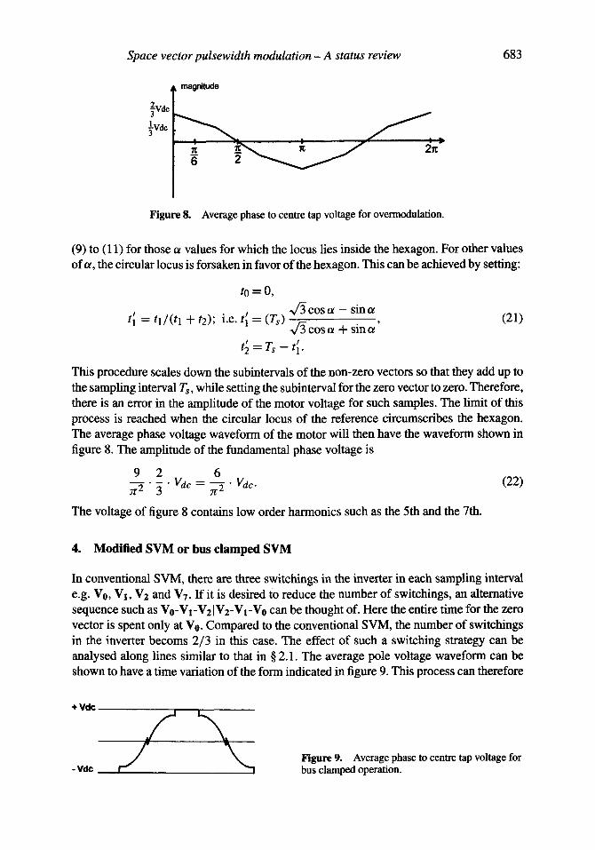
Figure 8. Average phase to centre tap voltage for overmodulation.
(9) to (11) for those a values for which the locus lies inside the hexagon. For other values of u, the circular locus is forsaken in favor of the hexagon. This can be achieved by setting:
t o = 0 ,
cos ot - sin oe t~ = t l / ( t l + t2); i.e. t~ = (Ts) x/~cosot + sinot' (21)
t~= Ts - t~.
This procedure scales down the subintervals of the non-zero vectors so that they add up to the sampling interval Ts, while setting the subinterval for the zero vector to zero. Therefore, there is an error in the amplitude of the motor voltage for such samples. The limit of this process is reached when the circular locus of the reference circumscribes the hexagon. The average phase voltage waveform of the motor will then have the waveform shown in figure 8. The amplitude of the fundamental phase voltage is
9 2 6 = Vec . (22)
The voltage of figure 8 contains low order harmonics such as the 5th and the 7th.
4. Modified SVM or bus clamped SVM
In conventional SVM, there are three switchings in the inverter in each sampling interval e.g. V0, V1, V2 and VT. If it is desired to reduce the number of switchings, an alternative sequence such as V0-VI-V2 IV2-Vt-V0 can be thought of. Here the entire time for the zero vector is spent only at V0. Compared to the conventional SVM, the number of switchings in the inverter becoms 2/3 in this case. The effect of such a switching strategy can be analysed along lines similar to that in § 2.1. The average pole voltage waveform can be shown to have a time variation of the form indicated in figure 9. This process can therefore
÷Vde
-Vde Figure 9. Average phase to centre tap voltage for bus clamped operation.
684 V T Ranganathan
be considered conceptually equal to a sine-triangle PWM, where a rectangular waveform at three times the sine frequency is added to each of the sine waves. Since one of the inverter phases is tied to a bus over 60 ° intervals, this technique has also been referred to as Bus Clamped SVM. This technique has the advantage that the lowest order harmonic generated is at a frequency 50% higher than that of normal SVM with the same switching rate. In addition, since there are only four swichings over a PWM period, there is less overhead in terms of loading timers, when it comes to a question of practical realisation. However, the performance in terms of harmonic content or loss factor is inferior to conventional SVM.
5. Extensions of space vector modulation
The majority of drives use a single inverter with a normal three phase ac motor. In high power drives, however, in order to limit the voltage and current ratings of the power devices, other configurations are also in use. Notable amongst these are: (i) the three-level inverter (Nabae et a11981; Stemmler 1994) and (ii) the split phase induction motor drive (Andresen 1981; Gopakumar et al 1993). These configurations extend the power rating of the system by using double the number of switches i.e.twelve. Space vector concepts can be extended to such configurations also in order to generate the pulse patterns, as outlined below.
5.1 SVM of three level inverter
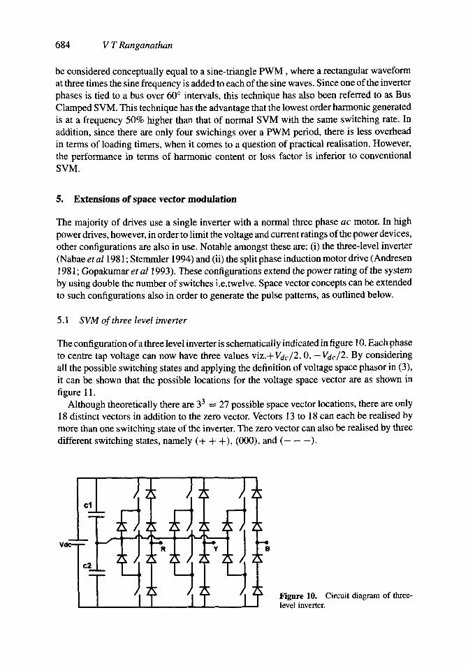
The configuration of a three level inverter is schematically indicated in figure 10. Each phase to centre tap voltage can now have three values viz.+Vdc/2, O, --Vdc/2. By considering all the possible switching states and applying the definition of voltage space phasor in (3), it can be shown that the possible locations for the voltage space vector are as shown in figure 11.
Although theoretically there are 33 = 27 possible space vector locations, there are only 18 distinct vectors in addition to the zero vector. Vectors 13 to 18 can each be realised by more than one switching state of the inverter. The zero vector can also be realised by three different switching states, namely (+ + +), (000), and ( - - - ) .
Figure 10. Circuit diagram of three- level inverter.
Space vector pulsewidth modulation - A status review 685
÷ ÷
+.
. 4 . .
÷ o .
- 4 , 4 ,
÷ - ÷
0-+
. . 4 ,
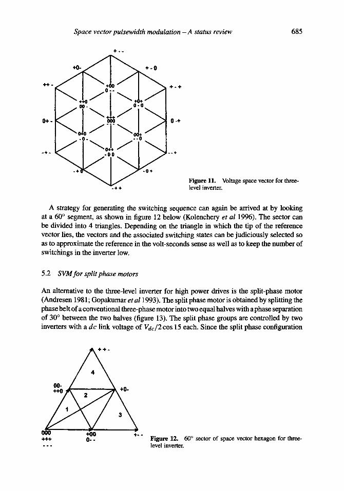
Figure 11. Voltage space vector for three- level inverter.
A strategy for generating the switching sequence can again be arrived at by looking at a 60 ° segment, as shown in figure 12 below (Kolenchery et al 1996). The sector can be divided into 4 triangles. Depending on the triangle in which the tip of the reference vector lies, the vectors and the associated switching states can be judiciously selected so as to approximate the reference in the volt-seconds sense as well as to keep the number of switchings in the inverter low.
5.2 SVM for split phase motors
An alternative to the three-level inverter for high power drives is the split-phase motor (Andresen 1981; Gopakumar et a11993). The split phase motor is obtained by splitting the phase belt of a conventional three-phase motor into two equal halves with a phase separation of 30 ° between the two halves (figure 13). The split phase groups are controlled by two inverters with a dc link voltage of Vdc/2 cos 15 each. Since the split phase configuration
000 4~0 ÷. . +++ O- -
Figure 12. 60 ° sector of space vector hexagon for three- level inverter.
686 V T R a n g a n a t h a n
Vdc 2cos75
_.+
!
INV#1
!
I INV#2
Y
I B / , .
R'
~R
(a) (b) Figure 13. Configuration of split-phase induction motor drive. (a) Block diagram of split- phase induction motor drive. (b) Orientation of MMF vectors produced by the coils of a split-phase machine.
is achieved by splitting the phase belts in two, the equivalent number of turns per phase for the new configuration is N s / 2 cos 15, where Ns is the equivalent number of turns for the three-phase configuration. Correspondingly, a link voltage of V d c / 2 cos 15 gives the same magnitude for the airgap flux in the new configuration as compared to the three phase inverter drive with a d c link voltage of Vdc.
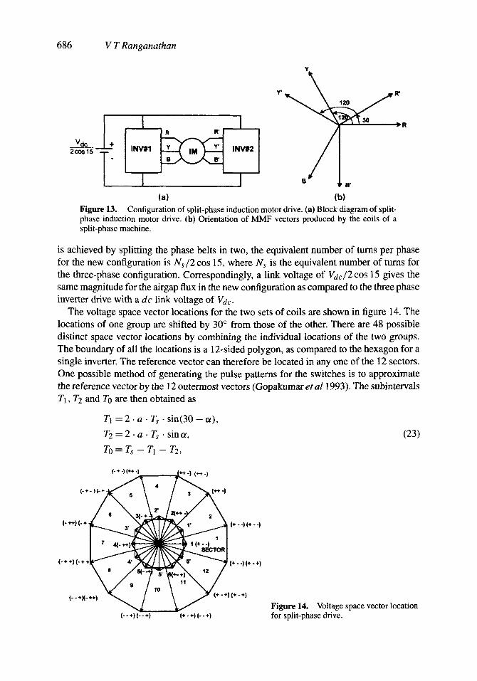
The voltage space vector locations for the two sets of coils are shown in figure 14. The locations of one group are shifted by 30 ° from those of the other. There are 48 possible distinct space vector locations by combining the individual locations of the two groups. The boundary of all the locations is a 12-sided polygon, as compared to the hexagon for a single inverter. The reference vector can therefore be located in any one of the 12 sectors. One possible method of generating the pulse patterns for the switches is to approximate the reference vector by the ! 2 outermost vectors (Gopakumar et a l 1993). The subintervals T1, T2 and To are then obtained as
TI = 2 . a • Ts • sin(30 - u),
7"2 = 2 . a • Ts • sin a, (23)
T0 = T,~ - T 1 - T : ,
(. + -) (~ -)
I - + - ~
1- ÷÷)1- + ~ N ~
I - ÷ ÷ ) l - ÷ ÷ ~ ~
÷ ÷÷} ~ J (--÷)1--÷)
~ ~-I (+÷-)
~ e r ~ 1+ . -I I t - ÷1
; ~ ÷ l ( ÷ +)
(+ - ÷) 1- - ÷) Figure 14. Voltage space vector location for split-phase drive.
Space vector pulsewidth modulation - A status review 687
tot
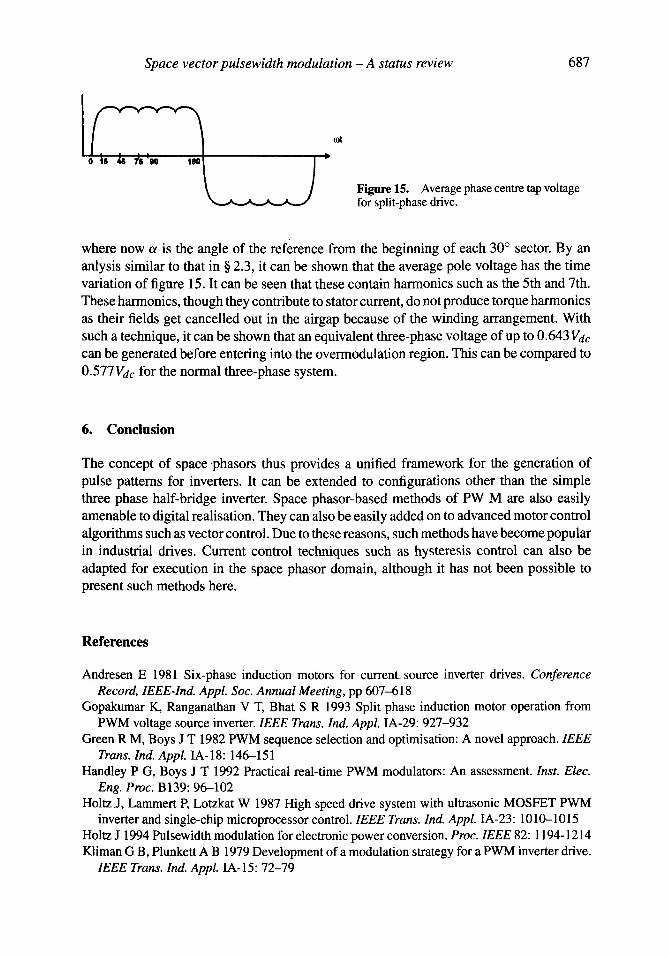
Figure 15. Average phase centre tap voltage for split-phase drive.
where now ot is the angle of the reference from the beginning of each 30 ° sector. By an anlysis similar to that in § 2.3, it can be shown that the average pole voltage has the time variation of figure 15. It can be seen that these contain harmonics such as the 5th and 7th. These harmonics, though they contribute to stator current, do not produce torque harmonics as their fields get cancelled out in the airgap because of the winding arrangement. With such a technique, it can be shown that an equivalent three-phase voltage of up to 0.643 Vdc can be generated before entering into the overmodulation region. This can be compared to 0.577 Vdc for the normal three-phase system.
6. Conclusion
The concept of space phasors thus provides a unified framework for the generation of pulse patterns for inverters. It can be extended to configurations other than the simple three phase half-bridge inverter. Space phasor-based methods of PW M are also easily amenable to digital realisation. They can also be easily added on to advanced motor control algorithms such as vector control. Due to these reasons, such methods have become popular in industrial drives. Current control techniques such as hysteresis control can also be adapted for execution in the space phasor domain, although it has not been possible to present such methods here.
References
Andresen E 19_81 Six-phase induction motors for current source inverter drives. Conference Record, IEEE-Ind. Appl. Soc. Annual Meeting, pp 607-618
Gopakumar K, Ranganathan V T, Bhat S R 1993 Split phase induction motor operation from PWM voltage source inverter. IEEE Trans. Ind. Appl. IA-29:927-932
Green R M, Boys J T 1982 PWM sequence selection and optimisation: A novel approach. IEEE Trans. Ind. Appl. IA-18:146--151
Handley P G, Boys J T 1992 Practical real-time PWM modulators: An assessment. Inst. Elec. Eng. Proc. B139:96--102
Holtz J, Lammert P, Lotzkat W 1987 High speed drive system with ultrasonic MOSFET PWM inverter and single-chip microprocessor control. IEEE Trans. Ind. Appl. IA-23:1010-1015
Holtz J 1994 Pulsewidth modulation for electronic power conversion. Proc. IEEE 82:1194-1214 Kliman G B, Plunkett A B 1979 Development of a modulation strategy for a PWM inverter drive.
IEEE Trans. Ind. Appl. IA-15:72-79

688 V T Ranganathan
Kolenchery S S, Vaidya V C, Madhu Mangal 1996 SVM-PWM strategy for high power 3-level inverters in variable frequency applications. Proc. IEEE Int. Conf. Power Electronic Drive and Energy Systems for Industrial Growth (PEDES'96) 1:197-200
Nabae A, Takahashi I, Akagi H 1981 A new neutral-point-clamped PWM inverter. IEEE Trans. Ind. Appl. IA-17:518-523
Pollmann A 1983 A digital puslewidth modulator employing advanced modulation techniques. IEEE Trans. Ind. Appl. IA-19:409--413
Schonung A, Stemmler H 1964 Static frequency changer with subharmonic control in conjunction with reversible variable speed AC drives. Brown Boveri Rev. 51: 555-577
Stemmler H 1994 High power industrial drives. Proc. IEEE 82:1266-1286 Van der Broek H W, Skudelni H, Stanke G V 1988 Analysis and realisation of a pulsewidth
modulator based on voltage space vectors. IEEE Trans. Ind. Appl. IA-24:142-150