Embed Size (px)
Citation preview
Spacehand: a multi-fingered robotic hand for space
Maxime Chalon* and Maximilian Maier, Wieland Bertleff, Alexander Beyer, Ralf BayerWerner Friedl, Philipp Neugebauer, Thomas Obermeier, Hans-Juergen Sedlmayr,
Nikolaus Seitz, Andreas Stemmer 1
1Institute of Robotics and Mechatronics, German Aerospace Center (DLR), Wessling, Germany*E-mail:[email protected]
ABSTRACTDespite the technological progress since the first attempts
of mankind to explore space, it appears that sending man inspace remains challenging. While robotic systems are not yetready to replace human presence, they provide an excellentsupport for astronauts during routine maintenance and haz-ardous tasks. This paper presents the ongoing development ofa space qualified multi-fingered robotic hand and highlightsthe most interesting challenges. The design concept, themechanical structure, the electronics architecture and thecontrol system are presented throughout this overview paper.
1. INTRODUCTIONThere exist a steady desired of mankind to explore the
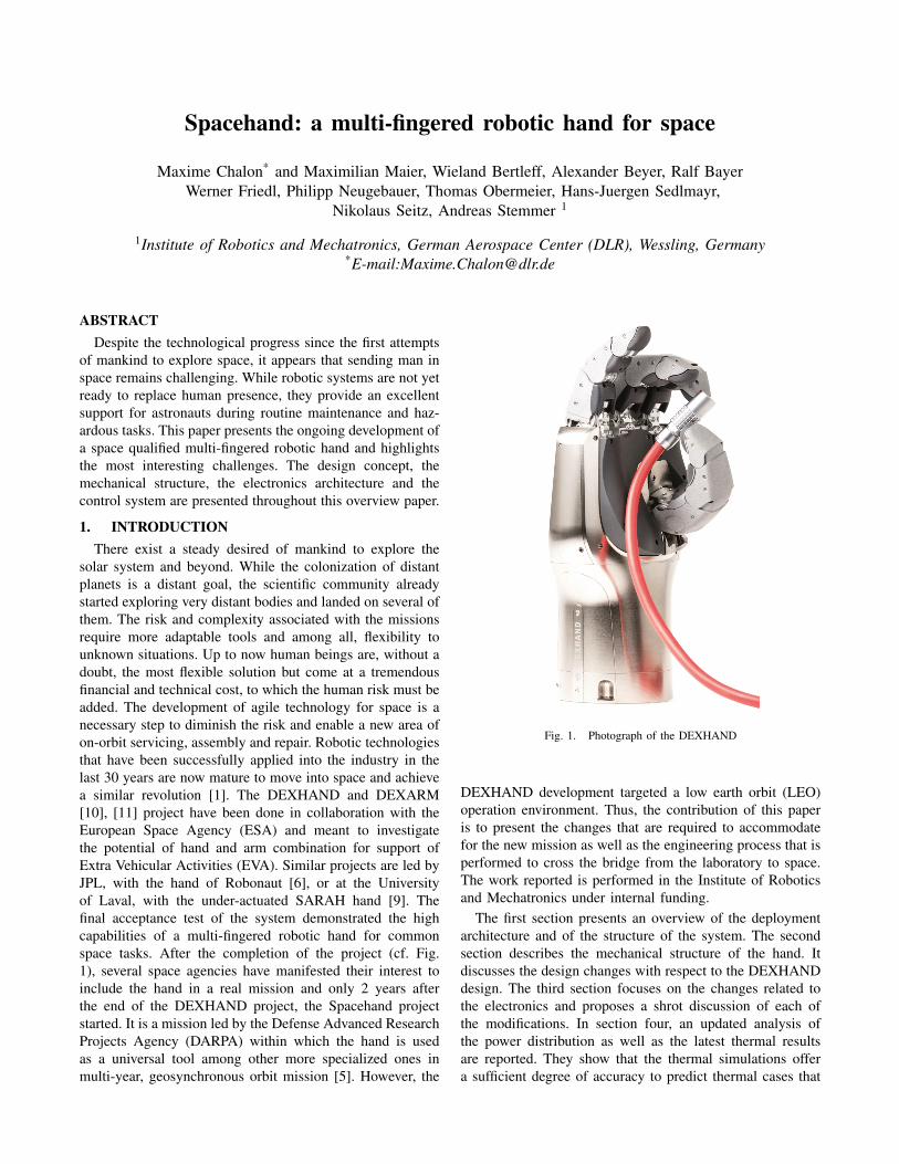
solar system and beyond. While the colonization of distantplanets is a distant goal, the scientific community alreadystarted exploring very distant bodies and landed on several ofthem. The risk and complexity associated with the missionsrequire more adaptable tools and among all, flexibility tounknown situations. Up to now human beings are, without adoubt, the most flexible solution but come at a tremendousfinancial and technical cost, to which the human risk must beadded. The development of agile technology for space is anecessary step to diminish the risk and enable a new area ofon-orbit servicing, assembly and repair. Robotic technologiesthat have been successfully applied into the industry in thelast 30 years are now mature to move into space and achievea similar revolution [1]. The DEXHAND and DEXARM[10], [11] project have been done in collaboration with theEuropean Space Agency (ESA) and meant to investigatethe potential of hand and arm combination for support ofExtra Vehicular Activities (EVA). Similar projects are led byJPL, with the hand of Robonaut [6], or at the Universityof Laval, with the under-actuated SARAH hand [9]. Thefinal acceptance test of the system demonstrated the highcapabilities of a multi-fingered robotic hand for commonspace tasks. After the completion of the project (cf. Fig.1), several space agencies have manifested their interest toinclude the hand in a real mission and only 2 years afterthe end of the DEXHAND project, the Spacehand projectstarted. It is a mission led by the Defense Advanced ResearchProjects Agency (DARPA) within which the hand is usedas a universal tool among other more specialized ones inmulti-year, geosynchronous orbit mission [5]. However, the
Fig. 1. Photograph of the DEXHAND
DEXHAND development targeted a low earth orbit (LEO)operation environment. Thus, the contribution of this paperis to present the changes that are required to accommodatefor the new mission as well as the engineering process that isperformed to cross the bridge from the laboratory to space.The work reported is performed in the Institute of Roboticsand Mechatronics under internal funding.
The first section presents an overview of the deploymentarchitecture and of the structure of the system. The secondsection describes the mechanical structure of the hand. Itdiscusses the design changes with respect to the DEXHANDdesign. The third section focuses on the changes related tothe electronics and proposes a shrot discussion of each ofthe modifications. In section four, an updated analysis ofthe power distribution as well as the latest thermal resultsare reported. They show that the thermal simulations offera sufficient degree of accuracy to predict thermal cases that
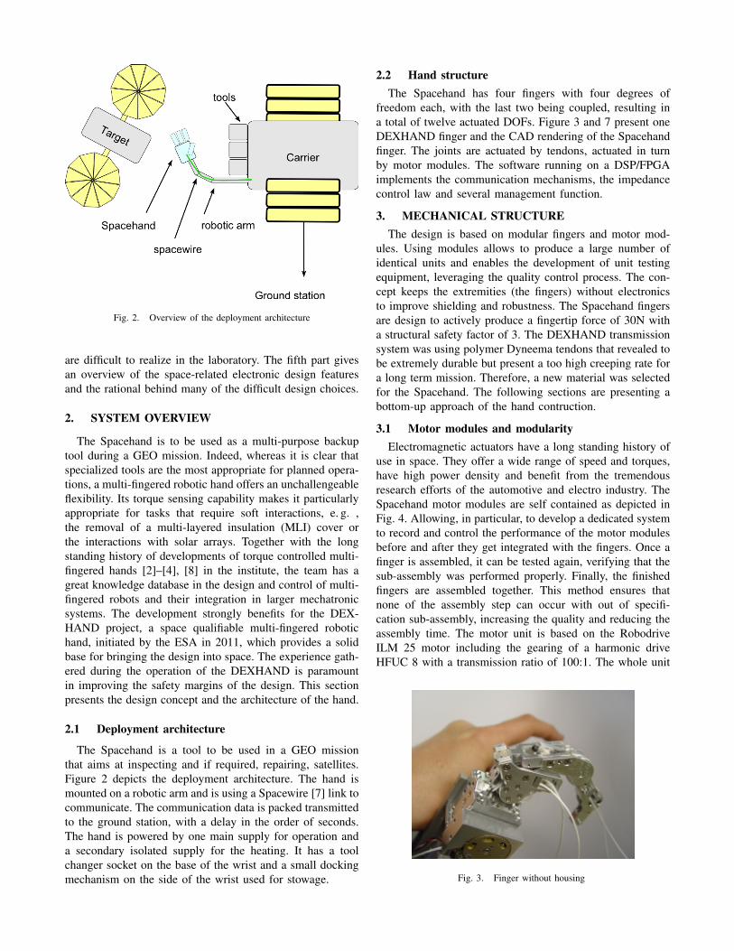
Fig. 2. Overview of the deployment architecture
are difficult to realize in the laboratory. The fifth part givesan overview of the space-related electronic design featuresand the rational behind many of the difficult design choices.
2. SYSTEM OVERVIEW
The Spacehand is to be used as a multi-purpose backuptool during a GEO mission. Indeed, whereas it is clear thatspecialized tools are the most appropriate for planned opera-tions, a multi-fingered robotic hand offers an unchallengeableflexibility. Its torque sensing capability makes it particularlyappropriate for tasks that require soft interactions, e. g. ,the removal of a multi-layered insulation (MLI) cover orthe interactions with solar arrays. Together with the longstanding history of developments of torque controlled multi-fingered hands [2]–[4], [8] in the institute, the team has agreat knowledge database in the design and control of multi-fingered robots and their integration in larger mechatronicsystems. The development strongly benefits for the DEX-HAND project, a space qualifiable multi-fingered robotichand, initiated by the ESA in 2011, which provides a solidbase for bringing the design into space. The experience gath-ered during the operation of the DEXHAND is paramountin improving the safety margins of the design. This sectionpresents the design concept and the architecture of the hand.
2.1 Deployment architecture
The Spacehand is a tool to be used in a GEO missionthat aims at inspecting and if required, repairing, satellites.Figure 2 depicts the deployment architecture. The hand ismounted on a robotic arm and is using a Spacewire [7] link tocommunicate. The communication data is packed transmittedto the ground station, with a delay in the order of seconds.The hand is powered by one main supply for operation anda secondary isolated supply for the heating. It has a toolchanger socket on the base of the wrist and a small dockingmechanism on the side of the wrist used for stowage.
2.2 Hand structureThe Spacehand has four fingers with four degrees of
freedom each, with the last two being coupled, resulting ina total of twelve actuated DOFs. Figure 3 and 7 present oneDEXHAND finger and the CAD rendering of the Spacehandfinger. The joints are actuated by tendons, actuated in turnby motor modules. The software running on a DSP/FPGAimplements the communication mechanisms, the impedancecontrol law and several management function.
3. MECHANICAL STRUCTUREThe design is based on modular fingers and motor mod-
ules. Using modules allows to produce a large number ofidentical units and enables the development of unit testingequipment, leveraging the quality control process. The con-cept keeps the extremities (the fingers) without electronicsto improve shielding and robustness. The Spacehand fingersare design to actively produce a fingertip force of 30N witha structural safety factor of 3. The DEXHAND transmissionsystem was using polymer Dyneema tendons that revealed tobe extremely durable but present a too high creeping rate fora long term mission. Therefore, a new material was selectedfor the Spacehand. The following sections are presenting abottom-up approach of the hand contruction.
3.1 Motor modules and modularityElectromagnetic actuators have a long standing history of
use in space. They offer a wide range of speed and torques,have high power density and benefit from the tremendousresearch efforts of the automotive and electro industry. TheSpacehand motor modules are self contained as depicted inFig. 4. Allowing, in particular, to develop a dedicated systemto record and control the performance of the motor modulesbefore and after they get integrated with the fingers. Once afinger is assembled, it can be tested again, verifying that thesub-assembly was performed properly. Finally, the finishedfingers are assembled together. This method ensures thatnone of the assembly step can occur with out of specifi-cation sub-assembly, increasing the quality and reducing theassembly time. The motor unit is based on the RobodriveILM 25 motor including the gearing of a harmonic driveHFUC 8 with a transmission ratio of 100:1. The whole unit
Fig. 3. Finger without housing

Fig. 4. CAD model of the motor modules
Fig. 5. Friction results for different temperatures and speed under vacuum
fits into a cylinder of 27 mm diameter and a length of 20mmwith a weight of 50g. The unit provides a continuous torqueof 2.4 Nm with peaks up to 9 Nm which is the maximumpeak torque of the gearing. A connection socket is directlyavailable on the motor unit, reducing the assembly time andimproving the unit robustness.
An extensive testing of the motor modules has beenperformed to establish a friction profile according to the tem-perature. Indeed, a detailed characterization of the lubricantbehavior is essential to compute the proper safety marginsas well as to detect any possible deviation from the nominalmotor module behavior. An example of characterizationunder vacuum is reported in Fig. 5. The tests have alsobeen repeated after a waiting period of 1 day under vacuumand did not reveal any significant deviation. Future tests willinclude a variable torque load and a longer waiting periodto detect possible cold welding phenomenon.
Fig. 6. left: tendon sample before irradiation, right: gliding polymer samplebefore irradiation
TABLE ITENDON SAMPLE RESULTS
Condition Load at rupture [N] Max. elongation [mm]Reference 1015 17
Irratiated 693Gy 1000 20Irratiated 1483Gy 1021 18
UV irradiation 997 31
3.2 Tendon testingA high performance Zylon fiber, woven by ”Marlow
Ropes” has been found to outperform the Dyneema fiberfor the application but the data regarding space use ofthis fiber was insufficient. Therefore, the tendons have beentested extensively. Tests included sun simulation under vac-uum, radiation testing with gamma radiation under vacuum,durability test for sliding over different materials and creeptest under simulated loading conditions. Simultaneously, thegliding material used for several guiding in the finger basewas submitted to the same tests. The ropes have a browncolor and a rough surface, c.f. Fig. 6. The results of the testsare summarized in Table I, II. None of the material showedany significant degradation under the expected environmentalcondition of the mission, thus are used for the Spacehanddesign.
3.3 Finger structureThe base joint of the finger MP (Metacarpal Proximal) is
realized with a Cardanic structure. Two motors are used todrive the base. This configuration advantageously allows tocombine the torque of two motors to actuate one DOF ofthe base joint. The Proximal Inter-Phalangeal joint (PIP) hasa fixed coupling with the Distal Inter-Phalangeal joint (DIP)with a ratio of 1 to 1 and is driven by the third motor. Figure7 shows a CAD model of the finger. From left to right are theMP, PIP and DIP joints. The respective link lengths are 40,30, and 23 mm. The finger structure is similar to the one usedfor DEXHAND, however the joints of the Spacehand fingersare using ball bearing instead of gliding joints. It reduces thejoint friction and consequently the tendon loads. As a result,the pretension can be reduced and can be maintained with
TABLE IIGLIDING POLYMER SAMPLE RESULTS
Condition Load at rupture [N] Max. elongation [mm]Reference 6108 62
Irratiated 693Gy 6035 34Irratiated 1483Gy 6106 58
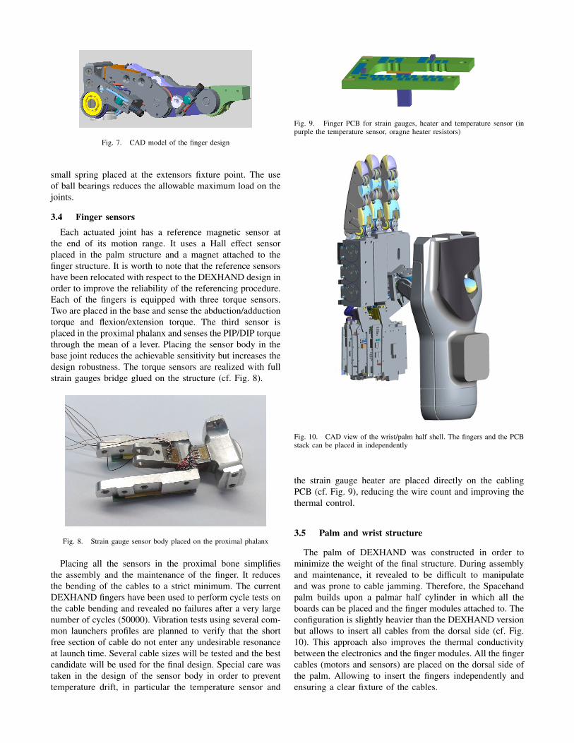
Fig. 7. CAD model of the finger design
small spring placed at the extensors fixture point. The useof ball bearings reduces the allowable maximum load on thejoints.
3.4 Finger sensorsEach actuated joint has a reference magnetic sensor at
the end of its motion range. It uses a Hall effect sensorplaced in the palm structure and a magnet attached to thefinger structure. It is worth to note that the reference sensorshave been relocated with respect to the DEXHAND design inorder to improve the reliability of the referencing procedure.Each of the fingers is equipped with three torque sensors.Two are placed in the base and sense the abduction/adductiontorque and flexion/extension torque. The third sensor isplaced in the proximal phalanx and senses the PIP/DIP torquethrough the mean of a lever. Placing the sensor body in thebase joint reduces the achievable sensitivity but increases thedesign robustness. The torque sensors are realized with fullstrain gauges bridge glued on the structure (cf. Fig. 8).
Fig. 8. Strain gauge sensor body placed on the proximal phalanx
Placing all the sensors in the proximal bone simplifiesthe assembly and the maintenance of the finger. It reducesthe bending of the cables to a strict minimum. The currentDEXHAND fingers have been used to perform cycle tests onthe cable bending and revealed no failures after a very largenumber of cycles (50000). Vibration tests using several com-mon launchers profiles are planned to verify that the shortfree section of cable do not enter any undesirable resonanceat launch time. Several cable sizes will be tested and the bestcandidate will be used for the final design. Special care wastaken in the design of the sensor body in order to preventtemperature drift, in particular the temperature sensor and
Fig. 9. Finger PCB for strain gauges, heater and temperature sensor (inpurple the temperature sensor, oragne heater resistors)
Fig. 10. CAD view of the wrist/palm half shell. The fingers and the PCBstack can be placed in independently
the strain gauge heater are placed directly on the cablingPCB (cf. Fig. 9), reducing the wire count and improving thethermal control.
3.5 Palm and wrist structure
The palm of DEXHAND was constructed in order tominimize the weight of the final structure. During assemblyand maintenance, it revealed to be difficult to manipulateand was prone to cable jamming. Therefore, the Spacehandpalm builds upon a palmar half cylinder in which all theboards can be placed and the finger modules attached to. Theconfiguration is slightly heavier than the DEXHAND versionbut allows to insert all cables from the dorsal side (cf. Fig.10). This approach also improves the thermal conductivitybetween the electronics and the finger modules. All the fingercables (motors and sensors) are placed on the dorsal side ofthe palm. Allowing to insert the fingers independently andensuring a clear fixture of the cables.

3.6 ShieldingThe emitted electromagnetic radiations are required to be
controlled to avoid possible interactions with the other satel-lite equipments, in particular communication antennas. In thecase of the Spacehand, similar to the DEXHAND, the designallows to create a nearly fully conductive enclosure and thusstrongly limit the emission points. The shield corruptionsare limited to the tendon insertion points. Conversely, theabsorbed radiations can potentially disturb the embeddedelectronics and create noise on the analog signals. Therefore,the exposed parts of the hand, that is the cabling in the fingerbases, are shielded and connected to the structure with a lowimpedance path.
4. ELECTRONICS
The electronics of the DEXHAND have been designedto be space ”qualifiable”’, that is most of the concepts andselected component are available in space grade and willfunction with the same performance level as what has beenachieved on the DEXHAND. The experience gathered withthe DEXHAND guided a number of wishes for the newelectronics. Several unused features are therefore plannedfor removal and several safety features are added. Finally,the currently envisioned mission itself imposes some designchanges, in particular w. r. t. the radiation levels. The hard-ening of the hand is realized by the combination of threedifferent elements:
• the use of radiation hardened parts.• housing the whole electronic system in a thick conduc-
tive aluminum shell.• stowing the hand in a protection box, providing an extra
shielding thickness and a thermal protection.However, due to the increased requirements regarding theradiation tolerance, some of the components used for theoriginal DEXHAND desgin must be replaced by larger ones.This led to a new selection of chips and offered new designsolutions. The following sections will present and discuss thedesign choices related to the following features:
• modification of the communication bus, from CAN toSpacewire
• motor controllers for higher radiation levels• memory layout and memory interface width• dosimeter
4.1 SpacewireSpacewire is a widely accepted communication standard
developed for Satellite communication system. The use ofSpacewire is not a major risk for the project since severalof the institute latest robotic platforms, such as the HandArm System [8], are also using Spacewire. Several Spacewirecores and LVDS drivers are commercially available for theFPGA and the main technology challenge is the memoryconnection between the IP core and the existing dual port raminterface. Different LVDS drivers provide a satisfying levelof radiation tolerance while satisfying the ECSS standard interms of speed and electrical characteristics. A breadboard
has been manufactured and assemble in order to ensure theproper functionality of the Spacewire core implementationand allow to verify the proper electrical characteristics ofthe communication lines. The test board is compatible withthe existing DEXHAND controller and thus allows an inde-pendent development and scheduling path.
4.2 Motor driversThe major electronic change from DEXHAND to Space-
hand is the need for the system to survive several yearsin GEO. The motor controller used for the DEXHANDdesign have been tested in house up to 25kRad but thisis insufficient for long term GEO operation. The motorcontroller implemented a six-step commutation with hallsensor feedback (cf. 11, concept A). It provided a gatedriving stage, an internal voltage regulation for hall sensorssupply and several safety features. In particular, it offeredan analog output for current sense and an analog input for acurrent limit. It allowed to implement a purely analog currentlimiting circuit, limiting the sum of the motor currents andnot the values individually. As a result it was possible to useall the available power for only one motor or share the powerequally between the running motors. The power distributionfeature is paramount to implement the input power limitationconstraints without sacrificing the dynamic performance ofthe hand.
The replacement design must offer similar or better fea-tures in order to offer the same level of performance. The newmotor driver solution is based on an integrated motor driverfrom Texas Instrument. The chip includes internal mosfets,resulting is a small board occupancy, and the required protec-tion circuitry. However, it does not integrate the commutationlogic, nor the analog current sensing/limiting features. There-fore, a current sensing circuitry has been added to providean analog current measurement to be connected to the totalcurrent measurement. The current limitation is achieved bymasking out the PWM signals directly in the FPGA (cf. 11,concept B). The chip has been tested in house and did notshow any performance degradation up to 40kRad (Si), itwill be tested for higher radiation doses in the next 2015campaign.
4.3 MemoryThe DEXHAND design was based on a combination
of radiation hardened flash memory and terrestrial MRAMcoupled to a latch-up detection circuit (cf. Fig. 12, A). Theflash memory was used to store the application code andthe MRAM to store the application parameters and severallong term house keeping values. The usage of the MRAMwas limited to a small number of bytes thus taking muchspace on the board for little functionality. The flash usedwas 32bits wide and resulted in a complex address trans-lation process for the boot loader code, making the linkingand flashing process relatively error prone. Recent studiesshowed that the reliability of radiation hardened MRAMallows to replace flash memories in many applications. As aresult, the Spacehand uses only a single, radiation hardened,
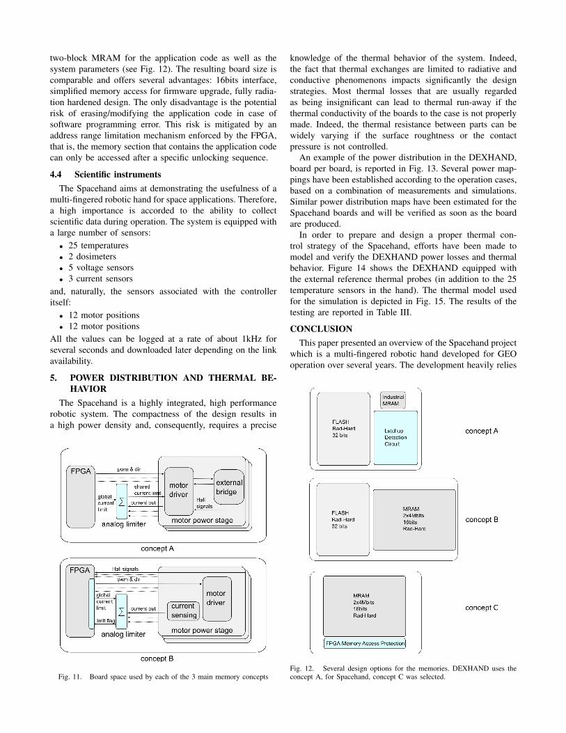
two-block MRAM for the application code as well as thesystem parameters (see Fig. 12). The resulting board size iscomparable and offers several advantages: 16bits interface,simplified memory access for firmware upgrade, fully radia-tion hardened design. The only disadvantage is the potentialrisk of erasing/modifying the application code in case ofsoftware programming error. This risk is mitigated by anaddress range limitation mechanism enforced by the FPGA,that is, the memory section that contains the application codecan only be accessed after a specific unlocking sequence.
4.4 Scientific instrumentsThe Spacehand aims at demonstrating the usefulness of a
multi-fingered robotic hand for space applications. Therefore,a high importance is accorded to the ability to collectscientific data during operation. The system is equipped witha large number of sensors:
• 25 temperatures• 2 dosimeters• 5 voltage sensors• 3 current sensors
and, naturally, the sensors associated with the controlleritself:
• 12 motor positions• 12 motor positions
All the values can be logged at a rate of about 1kHz forseveral seconds and downloaded later depending on the linkavailability.
5. POWER DISTRIBUTION AND THERMAL BE-HAVIOR
The Spacehand is a highly integrated, high performancerobotic system. The compactness of the design results ina high power density and, consequently, requires a precise
Fig. 11. Board space used by each of the 3 main memory concepts
knowledge of the thermal behavior of the system. Indeed,the fact that thermal exchanges are limited to radiative andconductive phenomenons impacts significantly the designstrategies. Most thermal losses that are usually regardedas being insignificant can lead to thermal run-away if thethermal conductivity of the boards to the case is not properlymade. Indeed, the thermal resistance between parts can bewidely varying if the surface roughtness or the contactpressure is not controlled.
An example of the power distribution in the DEXHAND,board per board, is reported in Fig. 13. Several power map-pings have been established according to the operation cases,based on a combination of measurements and simulations.Similar power distribution maps have been estimated for theSpacehand boards and will be verified as soon as the boardare produced.
In order to prepare and design a proper thermal con-trol strategy of the Spacehand, efforts have been made tomodel and verify the DEXHAND power losses and thermalbehavior. Figure 14 shows the DEXHAND equipped withthe external reference thermal probes (in addition to the 25temperature sensors in the hand). The thermal model usedfor the simulation is depicted in Fig. 15. The results of thetesting are reported in Table III.
CONCLUSIONThis paper presented an overview of the Spacehand project
which is a multi-fingered robotic hand developed for GEOoperation over several years. The development heavily relies
Fig. 12. Several design options for the memories. DEXHAND uses theconcept A, for Spacehand, concept C was selected.

TABLE IIITHERMAL TESTING RESULTS
Sensor Location Measured Simulated Abs. Difference Rel. Differencedegree Celcius degree Celcius degree Celcius percent
Analog1 53, 43 53, 61 +0, 07 +0, 13PI4 51, 80 52, 38 +0, 58 +1, 12PI3 51, 39 52, 38 +0, 99 +1, 93
Control 53, 52 57, 87 +4, 35 +8, 13PI2 50, 48 51, 59 +1, 11 +2, 20PI1 49, 97 51, 60 +1, 63 +3, 26
Analog2 52, 17 52, 86 +0, 69 +1, 32Backplane 54, 43 55, 66 +1, 23 +2, 26
Filter 54, 33 56, 52 +2, 19 +4, 03
Fig. 13. Power distribution in the DEXHAND depending for the ”idle”operation case
Fig. 14. Hand equipped with the measurement probes
Fig. 15. Thermal model
upon the previous DEXHAND design and on the experienceof DLR-RM in multi-fingered robot hands.
It is noteworthy to remark that the thermal behavior isprimarily dictated by the digital electronics since that arepermanently running. The thermal losses in the power chainare larger but can easily be mitigated by slowing down theoperation if required.
A major change with respect to the DEXHAND conceptis the change of radiation load and type due to the orbit andmission duration. It resulted in a change of design for thepower inverter parts, based on Texas Instrument integratedmotor driver. The current system is designed for a total doseof about 50kRad, which should provide a safe operationduring of 5 years in GEO.
Unsurprinsingly, the tendons are the most critical elementsof the drive system and, consequently, have been testedextensively. Zylon, a new tendon material was selectedbecause the previous material was inappropriate for longterm operation. A change of technology for the joints anda redesign of the tendon fixtures also increased the safetymargin with respect to the tendon durability.
The internal computing resources, combining the floatingcomputation speed of a DSP and the low-level parallelismof a FPGA allow the hand to achieve a real-time 1kHzjoint impedance control and provide advanced analysis andupgrade functionality. The Spacehand communicates at aspeed of 2Mbit/s over a spacewire LVDS connection asneeded for the mission but its design should accommodatehigher communication speeds.
ACKNOWLEDGMENT
The authors would like to thank the Spacehand team atDLR-RM as well as the NRL/DARPA for the collaborationopportunity. Thanks are also addressed to the ”Governmentof Upper Bavaria / Oberbayern Regierung” for the fundingsupport.
REFERENCES
[1] Rainer Bischoff and al. The KUKA-DLR lightweight robot arm -a new reference platform for robotics research and manufacturing.ROBOTIK, pages 1–8, 6 2010.
[2] Christoph Borst, Max Fischer, Steffen Haidacher, Hong Liu, and GerdHirzinger. DLR hand II: experiments and experiences with an an-thropomorphic hand. In Robotic and Automation, IEEE InternationalConference on, pages 702–707, 2003.
[3] J. Butterfaß, G. Hirzinger, S. Knoch, and H. Liu. DLR’s multisensoryhand part I: Hard- and software architecture. Robotic and Automation,IEEE International Conference on, 1998.
[4] Zhaopeng Chen, Neal Y.Lii, Thomas Wimboeck, Shaowei Fan,Minghe Jin, Christoph H. Borst, and Hong Liu. Experimental studyon impedance control for the five-fingered dexterous robot handDLR-HIT II. Intelligent Robots and Systems, IEEE InternationalConference on, 2010.
[5] DARPAtv. DARPA Phoenix Concept Video. https://www.youtube.com/watch?v=OeKzdk0sWjI. Accessed: 2015-04-29.
[6] M. A. Diftler, R. O. Ambrose, S. M. Goza, K.S. Tyree, and E.L.Huber. Robonaut Mobile Autonomy: Initial Experiments. Robotic andAutomation, IEEE International Conference on, pages 1437 – 1442,2005.
[7] ESA. ECSS-E-ST-50-12C. Technical report, European Space Agency,2008.
[8] Markus Grebenstein and Patrick van der Smagt. Antagonism fora highly anthropomorphic hand arm system. Advanced Robotics,(22):39–55, 2008.
[9] Bruno Rubinger, M. Brousseau, J. Lymer, Clement M. Gosselin,Thierry Laliberte, and Jean-Claude Piedboeuf. A novel robotic hand -SARAH for operations on the international space station. Proceedingof the ASTRA 2002 Workshop, 2002.
[10] A. Rusconi, PG. Magnani, T. Grasso, G. Rossi, J.F. Gonzalez Lodoso,and G. Magnani. DEXARM- a dexterous robot arm for spaceapplications. ASTRA, 2004.
[11] Armin Wedler, Maxime Chalon, and al. DLRs space qualifiable multi-fingered DEXHAND. ASTRA, 2011.


![Dexhand : a Space qualified multi-fingered robotic hand · hand/arm system. Similar projects are led by JPL, with the hand of Robonaut [1], or at the University of Laval, with the](https://img.pdfslide.net/doc/110x75/5f04d3547e708231d40fe593/dexhand-a-space-qualiied-multi-ingered-robotic-hand-handarm-system-similar.jpg)