Embed Size (px)
Citation preview

SPAM: 24.3MHz Transmitter and Receiver
Final Report
Andrew D. Baglino
March 18, 2004
Abstract
A radio transmitter/receiver pair operating at 24.3MHz was built to transmit baseband signals in the audiofrequency range. Successful transmission was achieved at distances up to 800m. The transmitter used adiscrete colpitts to achieve modulation directly at the transmission frequency and a GALI-5 power amp tobring the transmitted signal power to 13.5dBm into 50Ω. The receiver involved a heterodyning techniquewith a 300kHz intermediate frequency and could detect signals as low power as −120dBm. It consisted ofa low noise amplifier with 21dBm power gain and 50Ω input impedance followed by SA612 mixer with a24MHz local crystal oscillator and 20dB conversion gain. The 300kHz intermediate frequency signal wasthen amplified by two LM7171A gain stages with 52dB gain and filtered by a 4-pole Butterworth band-passfilter. Finally a LM565 phase-locked-loop with 10mV minimum input signal was used to demodulated thesignal back to audio frequencies with 1%THD.

1 Design Theory
Figure 1 below shows the overall designed system at a glance. This section will cover the design specificationsand final design of each block.
Figure 1: System Block Diagram
1.1 Transmitter
The overall transmitter was specified as follows:
• Supply Rails: 9V and 0V• Carrier Frequency fc = 24.3MHz• Signal Bandwidth ∆f = ±50kHz
To meet these specifications, a discrete colpitts oscillator using a voltage controlled diode varactor wasimplemented, effectively doing frequency modulation at the transmission frequency. I chose this design overa chip-based heterodyned approach because it had higher output power and slightly better audio quality.A potentiometer-tuned audio amp was used to bring the desired audio source to the amplitude required(250mV ) to get 100kHz transmission bandwidth from the colpitts. Finally, a GALI-5 power amp increasesthe colpitts’ transmission strength for final FM broadcasting via an antenna.
Colpitts Design
A colpitts oscillator is simply the combination of a resonator with an active device, so to turn it into a FMmodulator, we simply need to make the resonance frequency variable. The active component in my colpitts
1

is a Toshiba 2SC3302 BJT in common-base configuration. I achieved variability using the Vbias controlledinput capacitance of the base-emitter PN junction of a 2N3904 NPN transistor. To get sustained oscillations,a capacitor divider with n ≈ 1
3 between collector and emitter sets the feedback gain. An LC tank sets thecarrier frequency, and the capacitor divider in the tank contains a variable capacitor to allow much-neededtuning flexibility. A tapped inductor configuration in the tank is used to transform the expected 50Ω inputimpedance of the power amp to a value in the kΩ so as not to load the oscillator and get higher gain. Thisdesign performed well as soon as the solder dried, with tunable stable oscillations achieved once all capacitivebody parts were away from the board, both with collector currents of .5mA and 3.5mA, corresponding toRe = 6.8kΩ and 1kΩ, respectively.
Power Amp Design
The Power Amplifier used, the GALI-5, is supposed to be rather plug-and-play, claiming to have S11 and S22
of < .1, though the datasheet does not specify these Sparameters for input frequencies below 100MHz. Ratherthan designing matching networks, I decided to see how it performed first. Its major design considerationswere in biasing its DC output voltage and implementing a sufficient inductive choke to direct the 24.3MHzsignals out the antenna and not onto the voltage rails.
The actual soldering of the surface mount GALI-5 was somewhat of a challenge, but I did not run intoany serious problems getting it up and running once it was firmly mounted. Although the input impedanceof the amplifier ended up being near spec, the output was way off. Nonetheless, I decided to focus myattention on my receiver during the weeks before Demo day. If I had more time, I would have attemptedimpedance matching between the amplifier output and the antenna, which would have likely helped me get5 or more dB power gain out of it.
1.2 Receiver
Design of the receiver was standard heterodyned FM reception. The 24.3MHz input FM wave, after passingthrough a simple LC filter, was amplified via a common-emitter low-noise amplifier (LNA) with shunt-shuntfeedback. A matching network was implemented to transform down the 1.5kΩ input impedance of the SA612multiplier in the next stage. A local 24MHz crystal oscillator was multiplied with the LNA output signalby the SA612 to produce an intermediate frequency signal centered at 300kHz. The IF Amp provided finalgain and filtering of unwanted frequencies before an LM565 phase-locked-loop demodulated the amplifiedsignal. The audio frequency output of the PLL was then amplified by a LM386 low-voltage audio amplifierwith tunable gain capable of driving my low impedance (50Ω) headphones.
LNA Design
The initial LNA was designed to meet the following specifications:
• Input Impedance (Rin): 50Ω• Output Impedance (Rout): 50Ω• S21 > 12dB• Collector Current (Ic): 4mA• Collector-Emitter Voltage (VCE): > 1V• Power consumption: as small as possible
To meet these specifications, a common-emitter amplifier with broadband shunt-shunt feedback and a tunedload was implemented. In both a spreadsheet model and HSpice, I tried to best nail down component valuesto meet most of the above constraints.
Once in lab, I found getting the impedance values that HSpice and my spreadsheet had predicted whilemaintaining the gain I wanted to be rather difficult. Changing the feedback resistor would help with gain butthen the impedances would be too high. Primarily, my major problem was that I had uneven impedances–thereal input impedance was 75Ω while my real output impedance was 44Ω.
2

After playing around with various feedback and emitter resistors, changing gain and impedance config-urations, I decided eventually to go back to my simulated values, ignore my input impedance (for via thefeedback resistor, it would change when I created a matching network on the output) and go ahead to matchto both the reactive and resistive components on the LNA output.
In preparing for demo day and the final project, I decided to keep the LNA topology unchanged, in partbecause I had succeeded in creating a rather successful match to my impedances, and also because I wasseeing wonderful system performance, with minimum detectable signals in the −125dBm range. Certainly,by having broadband feedback I was introducing more noise than necessary. However, the matching networkI created should attenuate errant signals simply by the virtue of being mismatched at frequencies other than24.3MHz.
The only addition for demo day was to add a simple LC filter to the input in an effort to filter out thosenagging 48MHz and 96MHz KRON4 TV and country radio stations. As they were both multiples of mycrystal local oscillator, their often greater power levels would feedthrough my multiplier, get downshiftedto 300kHz, and drown out the 24.3MHz signals of interest. The input filter solved that problem, and bymaking the inductor myself, I was able to test my inductor-winding skills.
LNA-Mixer Matching Design
A matching network on the LNA output was needed to transform down the mixer input impedance to matchmy amplifier output impedance. As I was designing a match anyways, I decided to worry less about gettingreal LNA output impedances and more about my matching design. The final matching network is shownbelow, in Figure 2. As the Figure shows, the match had to taken into account the capacitive and real outputimpedances of my LNA and the 3pF and 1.5kΩ input impedance of the multiplier.
Figure 2: Matching Network Design
The design has many benefits resulting from the two degrees of freedom enabled by the variable capacitors.The variable cap in parallel with the inductor in essence acts as a variable inductor which not only cancelsout the capacitive multiplier input, but allows me to dial in the Qp and thus Rseq I desire. The other variablecapacitor changes allows me to resonate out all of Lseq
but the exact amount of inductance necessary tocancel out the capacitive output impedance of my LNA.
Besides matching perfectly at 24.3MHz, this match has the added benefit of acting as an attenuator atother frequencies. It is in essence both an impedance match and an LC bandpass filter. This was an excitingside benefit of my matching design process that I only noticed in retrospect.
The network was rather easy to fit on the board and work with. Its flexibility proves to be very helpful,and feedback of the matched load helped with my input impedance, as well.
3

Multiplier Design
The SA612 multiplier is a very handy part. It is a four quad multiplier that also is set up to have alocal oscillator (LO). Using application note AN1983, a fundamental mode crystal oscillator at 24MHz wasintegrated into the SA612 using a capacitor divider feedback system similar to that in the transmitter’scolpitts. The multiplier not only multiplies the LNA output with the LO, it should also provide a certaindegree of conversion gain (gconv) to the downshifted 300kHz signal. The multiplier worked as expected inlab and no changes were made to it for demo day.
Intermediate Frequency Amplifier Design
The IF Amp was specified to perform as follows:
• Gain: 5000VV
• Center Frequency: 300kHz• Bandwidth: 100kHz• Filter Topology: 4-pole Maximally Flat
The basic goal of the IF Amplifier is to amplify the signals detected by the LNA and multiplied down bythe mixer to amplitudes that the PLL can demodulate. Also, because the PLL has a large lockable range, wewant to filter out all those frequencies we are not interested in. This should also help with the signal-to-noiseratio of the input signal to the PLL. The amp was designed in a two stage fashion using two LM7171 op-ampswith voltage gain of 100 and an intermediate 4-pole butterworth filter. The final filter design, the productof the EE133 filter cookbook and a spreadsheet model, is shown below.
Figure 3: Filter Design
I initially had problems implementing the second amplification stage. With it connected, the overallamp would oscillate strongly at frequencies from 300kHz − 350kHz. Interestingly enough, even with thisoscillation, the overall receiver would work surprisingly well. The circuit would oscillate at the inputtedfrequency regardless of input amplitude–but only in the frequency range above. If the IF Amp was spec’dto operate with a center frequency of 325kHz with 50kHz bandwidth, I’d have been all set.
The reason for the oscillation ended up being poor circuit layout. Some of my lead wires between stageswere crossing over inductors they probably shouldn’t have. After re-soldering the filter in a better, morecompact and less coupling-prone manner, the oscillations were gone and I had a robust filter with appropriateperformance.
Phase Locked Loop and Audio Amp
The LM565 PLL was easily designed and implemented. One concern was setting the free-running frequency,done using the proper timing capacitor and resistor on the PLL’s VCO. The other design issue was the
4

bandwidth of the integrative filter in the PLL’s feedback loop–again choosing the proper capacitor value wasall that was necessary.
I chose to use the LM386 low-voltage audio amp chip on the PLL output because the output impedanceof the PLL (≈ 1kHz) was too high to drive my 50Ω headphones with any significant power. I used thedatasheet default configuration, giving me max gain of 20fracV V , which for all cases is more than enough.
2 Performance
2.1 Transmitter
My transmitter seemed to be blessed with good behavior throughout its tenure. I experienced few stabilityproblems, even when moving from inside to outside, hot to cold–all that was necessary was a little workwith a screwdriver, and everything would be okay. Of course–whenever a new antenna was connected or adifferent audio source, I would need to re-tune it.
The transmitter was put to the test near my home towards the end of the quarter. I placed it in thehot sun on the roof of a car on Emerson St. in downtown Palo Alto (a rather straight tree-lined surbubanavenue) and took off on my bike. With trees and power-lines overhead, moving trucks and cars aplenty onthe road, I was still able to pick up the signal 1/2 mile away in either direction. Overall characteristics ofinterest are shown in the below table.
DC Power Total 810mWPower Amp 720mW 89%Colpitts 63mW 7.8%Audio Amp 27mW 3.3%
Output Power 13.5dBm into 50Ω loadAudio Range 20Hz − 17kHz human ear is the limiting factorBandwidth(Max) ±60kHzMaximum Transmitted ≈ 800m with cars, trees, and power lines in the wayDistanceBattery Life 150min before voltage drops below 7V
Table 1: Overall Transmitter Characteristics
Colpitts Performance
The discrete colpitts performed very well throughout, providing -3dbm power into the power amp. Thesensitivity k was ≈ 185kHz
V and most linear nearest the diode varactor’s DC bias voltage. With a 10kΩattenuating resistor on the output of the audio amp, I was able to effectively limit the bandwidth of myoutput signal to 120kHz while maintaining a good deal of dynamic range–the audio amp had max gain of100V
V . Also, with my choice of capacitors in the feedback capacitor divider allowed my quite a large tuningrange for the carrier frequency: 23.83 − 26.93MHz. This comes in handy, for if the power amp has anyreactive components in its input impedance, it will change my ω = 1
sqrtLC resonance frequency, and thus Ineed significant tuning range to overcome such variability.
Power Amp Performance
The GALI-5 power amp is an interesting chip. From the datasheet, you’d think it was a wonder-chip–providing consistent reflection coefficients of .1 or less and 20dB power gain over a large frequency range.However, when actually soldered on and functioning, I found the power gain to be stable at 16.5dBm andthe input and output impedance as shown in the below table.
5

Frequency Zin S11 Zout S22
10Mhz 88 + 0jΩ 0.275 3 + 0jΩ 0.88624.3Mhz 90 + 0jΩ 0.287 4 + 9jΩ 0.86530Mhz 87 + 0jΩ 0.275 4.5 + 10jΩ 0.84540Mhz 86 + 2jΩ 0.265 5 + 14jΩ 0.831
Table 2: Power Amp S-Parameters
It does seem that the performance of the amp improves with higher frequency, so perhaps at 100MHzthe amp would be at spec. But at 24.3MHz, the amp is far from matched to 50Ω at either the input orthe output. Nonetheless, it puts out 13.5dBm into a 50Ω load, so I cannot complain. Certainly, a greatimprovement in performance could be expected with an antenna-matching network, and would be the nextthing I would tackle on the transmitter if I had time. As far as linearity was concerned, I found the 1dbcompression point to be around 3dBm and the IP3 point to be 13dBm, both well above my Colpitts inputpower of −3dBm.
2.2 Receiver
The receiver was more of a rollercoaster ride. Its lowest point of the entire quarter was when I turned it on tofind my minimum detectable signal had fallen by 40dB–and what had I done? Wired up a power switch intothe circuit. I was able to see pass these lows, though, and all in all, the receiver performed nicely, providingme with sparkling clear signals and an ear ever-ringing with 1kHz tones.
Key to the receiver was the antenna impedance. It’s laughable the amount of difference holding theantenna at its base makes. In a way, it makes me want to go into the antenna-making business, because thedifference in standing-wave ratio between a held antenna and a loose one can be more than 20. That aside,when you hold the lab antennas, they generally settle at 50Ω, and thus I matched to that impedance rathersuccessfully, achieving S11 ≈ .01 or better with conscientious tweaking of my matching network.
From the noise perspective, the other key block was the IF Amp, where the introduced noise was evident.By turning down the gain on the second stage, my minimum detectable signal went from −115dBm to−125dBm. The noise introduced by the high gain of the second stage was overpowering whatever benefitthere was from the amplified signal. This noise could be due in part to my use of standoffs on the secondgain stage, which was a result of the funny oscillations I was having in the filter, which I mentioned above.
The overall characteristics of my receiver are as shown in the below table.
DC Power Total 306mWIF Amp 100mW 32.7%Audio and Vref 93mW 30.3%PLL 54mW 17.6%LNA 45mW 14.7%Mixer 14mW 4.7%
Voltage Gain 82dB pre PLLAudio Range 20Hz − 17kHz human ear is the limiting factorLinearity 5.5%Minimum Detectable Signal −120dBm better or worse, depending on lab conditionsBattery Life 720min before voltage drops below 7V
Table 3: Overall Transmitter Characteristics
6

LNA Performance
The LNA is the most important part of the transmitter, as it is the only block to need to match to theantenna, it provides the initial gain, and the noise of every block after the LNA is divided by the LNA’s gain.The final noise figure of my LNA was 4.75dB (taken with the Mixer’s LO turned off), compared with theblock’s 21dBm power gain under operating conditions. The gain and linearity characteristics of the amp,measured in isolation, are both shown in Figure 4, below.
Figure 4: LNA Performance
The figure denotes a power gain of only 15dBm below the 1dB compression point, due to the fact that I didthis analysis without the matching network. Without matching, the LNA’s impedances are Zin = 75−7.6jΩand Zout = 44 − 9.6jΩ, so the loss of 6dB power gain is expected with the mismatch. With both the 1dBand IP3 points well above signal powers I expect to encounter, the linearity of the LNA is not a problem.Also, matching is not a problem under operating conditions, as mentioned above, as long as you hold theantenna firmly at its base while receiving.
Although I did not redesign the LNA for Demo Day, I feel the initial circuit along with the matchingnetwork had performance to justify that decision. The final change I did make was to include an series LCbandpass filter centered at 24.3MHz at the input, crucial for attenuating those annoying signals near thehigher order harmonics of the crystal LO on the mixer. In order to avoid attenuation of the input signal Iwound my own inductor, achieving a QL in the 1000s.
Mixer Performance
The mixer ended up being an integral part of the signal gain chain, much to my surprise. After having ahorrible time getting the SA612 to have any gconv in Lab 1, much to my surprise when I built it on the newboards, it performed wonderfully, providing conversion gain of 10V
V from the 24.3MHz matching network
7

output to the IF Amp input. The local oscillator was easy to put together, and put out signals at 680mVpp.The linearity and gain attributes of the LNA are shown in Figure 5. With 1db and IP3 points of -28 and−14dBm, to avoid linearity issues, the input to the LNA needs to be lower than -50dBm, accounting for itsgain.
Figure 5: Mixer Linearity
Figure 6: Pre and Post-Redesign IF Amp Frequency Responses
8
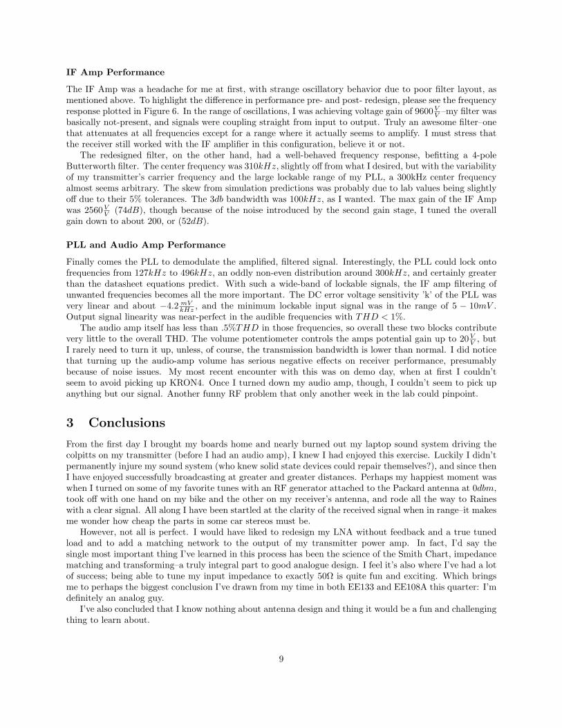
IF Amp Performance
The IF Amp was a headache for me at first, with strange oscillatory behavior due to poor filter layout, asmentioned above. To highlight the difference in performance pre- and post- redesign, please see the frequencyresponse plotted in Figure 6. In the range of oscillations, I was achieving voltage gain of 9600V
V –my filter wasbasically not-present, and signals were coupling straight from input to output. Truly an awesome filter–onethat attenuates at all frequencies except for a range where it actually seems to amplify. I must stress thatthe receiver still worked with the IF amplifier in this configuration, believe it or not.
The redesigned filter, on the other hand, had a well-behaved frequency response, befitting a 4-poleButterworth filter. The center frequency was 310kHz, slightly off from what I desired, but with the variabilityof my transmitter’s carrier frequency and the large lockable range of my PLL, a 300kHz center frequencyalmost seems arbitrary. The skew from simulation predictions was probably due to lab values being slightlyoff due to their 5% tolerances. The 3db bandwidth was 100kHz, as I wanted. The max gain of the IF Ampwas 2560V
V (74dB), though because of the noise introduced by the second gain stage, I tuned the overallgain down to about 200, or (52dB).
PLL and Audio Amp Performance
Finally comes the PLL to demodulate the amplified, filtered signal. Interestingly, the PLL could lock ontofrequencies from 127kHz to 496kHz, an oddly non-even distribution around 300kHz, and certainly greaterthan the datasheet equations predict. With such a wide-band of lockable signals, the IF amp filtering ofunwanted frequencies becomes all the more important. The DC error voltage sensitivity ’k’ of the PLL wasvery linear and about −4.2 mV
kHz , and the minimum lockable input signal was in the range of 5 − 10mV .Output signal linearity was near-perfect in the audible frequencies with THD < 1%.
The audio amp itself has less than .5%THD in those frequencies, so overall these two blocks contributevery little to the overall THD. The volume potentiometer controls the amps potential gain up to 20V
V , butI rarely need to turn it up, unless, of course, the transmission bandwidth is lower than normal. I did noticethat turning up the audio-amp volume has serious negative effects on receiver performance, presumablybecause of noise issues. My most recent encounter with this was on demo day, when at first I couldn’tseem to avoid picking up KRON4. Once I turned down my audio amp, though, I couldn’t seem to pick upanything but our signal. Another funny RF problem that only another week in the lab could pinpoint.
3 Conclusions
From the first day I brought my boards home and nearly burned out my laptop sound system driving thecolpitts on my transmitter (before I had an audio amp), I knew I had enjoyed this exercise. Luckily I didn’tpermanently injure my sound system (who knew solid state devices could repair themselves?), and since thenI have enjoyed successfully broadcasting at greater and greater distances. Perhaps my happiest moment waswhen I turned on some of my favorite tunes with an RF generator attached to the Packard antenna at 0dbm,took off with one hand on my bike and the other on my receiver’s antenna, and rode all the way to Raineswith a clear signal. All along I have been startled at the clarity of the received signal when in range–it makesme wonder how cheap the parts in some car stereos must be.
However, not all is perfect. I would have liked to redesign my LNA without feedback and a true tunedload and to add a matching network to the output of my transmitter power amp. In fact, I’d say thesingle most important thing I’ve learned in this process has been the science of the Smith Chart, impedancematching and transforming–a truly integral part to good analogue design. I feel it’s also where I’ve had a lotof success; being able to tune my input impedance to exactly 50Ω is quite fun and exciting. Which bringsme to perhaps the biggest conclusion I’ve drawn from my time in both EE133 and EE108A this quarter: I’mdefinitely an analog guy.
I’ve also concluded that I know nothing about antenna design and thing it would be a fun and challengingthing to learn about.
9

Finally, SPAM has got me hooked–I’ve been inspired to build a neighborhood radio station. I’m currentlytrying to improve the stability of the third harmonic of the discrete colpitts. After demo day I tried re-tuningits fundamental oscillation to a range of 90−100MHz, and immediately burned out my power amp and hada colpitts oscillating at 400MHz, instead. After playing around with a series of different capacitor values Isettled on transmitting the third harmonic of a colpitts tuned to the 30− 35Mhz range (the third harmonicbroadcasts from 90 − 115Mhz @ −6dBm), which seems to work when I hold down a screwdriver on thevariable capacitor. I’ve been able to get successful transmission to my radio without the screwdriver onlywhen there is very little ”people capacitance” in the room, and for brief periods. More research is definitelywarranted.
10

Appendix: Characterization
1 Receiver
DC Power Drain: 306mWGain (Pre-PLL): 82dBBandwidth: 20Hz − 17kHzLinearity (THD), Audio Frequencies: 5.5%Minimum Detectable Signal: −120dBmBattery Life (@7V ): 720min
1.1 Low Noise Amplifier
DC Power Drain: 45mWGain (Power): 21dBmLinearity (1dBCompression): −33dBmLinearity (Third Order Intercept): −21dBmNoise Figure: 4.75dBInput Impedance (Matched, Unmatched): 75− 7.6jΩ, 50ΩOutput Impedance: 44− 9.6j
1.2 SA612 Mixer
DC Power Drain: 14mWGain (Conversion): 10V
VLinearity (1dBmCompression): −28dBmLinearity (Third Order Intercept): −14dBmLO Input Voltage: 680mV
1.3 Intermediate Frequency Amplifier
DC Power Drain: 100mWOperating Gain (Tuned Low for Noise): 52dB V
V
Potential Gain: 74dB VV
Filter Center Frequency: 310kHzFilter Bandwidth: 100kHz
1.4 Phase Locked Loop
DC Power Drain: 54mWSensitivity ’k’: −4.2 mV
kHzCenter Frequency: 300kHzLock’d Frequency Frequency Range (1V input signal): 127− 496kHzMinimum Input Signal: 10mVLinearity (THD), Audio Frequencies 1%
11

Appendix: Characterization
2 Transmitter
DC Power Drain: 810mWOutput Power: 13.5dBmAudio Range: 20Hz − 17kHzBandwidth (Max): 120kHzMaximum Distance: 800mBattery Life(@6V ): 150min
2.1 Audio Amp
DC Power Drain: 27mWGain Voltage (Max): 100V
VLinearity (THD): −25dB
2.2 Discrete Colpitts VCO
DC Power Drain: 63mWSensitivity ’k’: 185kHz
VTuning Range : 23.83− 26.93MHzMax Bandwidth: 120kHzOutput Power: −3dBm
2.3 Power Amp
DC Power Drain: 720mWGain (Power): 16.5dBmEfficiency : 3.2%Input Impedance: 90ΩOutput Impedance: 4 + 9jΩ
12