Embed Size (px)
Citation preview

SPEAR™ Single-Phase Recloser System Installation and Operation Instructions
COOPER POWERSERIES
Reclosers MN280048EN
Effective June 2016Supersedes S280-101-1 (May 2015)

iINSTALLATION AND OPERATION INSTRUCTIONS MN280048EN June 2016
DISCLAIMER OF WARRANTIES AND LIMITATION OF LIABILITY
The information, recommendations, descriptions and safety notations in this document are based on Eaton Corporation’s (“Eaton”) experience and judgment and may not cover all contingencies. If further information is required, an Eaton sales office should be consulted. Sale of the product shown in this literature is subject to the terms and conditions outlined in appropriate Eaton selling policies or other contractual agreement between Eaton and the purchaser.
THERE ARE NO UNDERSTANDINGS, AGREEMENTS, WARRANTIES, EXPRESSED OR IMPLIED, INCLUDING WARRANTIES OF FITNESS FOR A PARTICULAR PURPOSE OR MERCHANTABILITY, OTHER THAN THOSE SPECIFICALLY SET OUT IN ANY EXISTING CONTRACT BETWEEN THE PARTIES. ANY SUCH CONTRACT STATES THE ENTIRE OBLIGATION OF EATON. THE CONTENTS OF THIS DOCUMENT SHALL NOT BECOME PART OF OR MODIFY ANY CONTRACT BETWEEN THE PARTIES.
In no event will Eaton be responsible to the purchaser or user in contract, in tort (including negligence), strict liability or otherwise for any special, indirect, incidental or consequential damage or loss whatsoever, including but not limited to damage or loss of use of equipment, plant or power system, cost of capital, loss of power, additional expenses in the use of existing power facilities, or claims against the purchaser or user by its customers resulting from the use of the information, recommendations and descriptions contained herein. The information contained in this manual is subject to change without notice.
ii INSTALLATION AND OPERATION INSTRUCTIONS MN280048EN June 2016
Contents
DISCLAIMER OF WARRANTIES AND LIMITATION OF LIABILITY . . . . . . . . . . . . . . . . . . . . . . . . . . . . . . . . . . . . i
Safety for life . . . . . . . . . . . . . . . . . . . . . . . . . . . . . . . . . . . . . . . . . . . . . . . . . . . . . . . . . . . . . . . . . . . . . . . . . . . . . iv
Safety information . . . . . . . . . . . . . . . . . . . . . . . . . . . . . . . . . . . . . . . . . . . . . . . . . . . . . . . . . . . . . . . . . . . . . . . . . ivSafety instructions . . . . . . . . . . . . . . . . . . . . . . . . . . . . . . . . . . . . . . . . . . . . . . . . . . . . . . . . . . . . . . . . . . . . . . . . . . . . . . iv
Product information . . . . . . . . . . . . . . . . . . . . . . . . . . . . . . . . . . . . . . . . . . . . . . . . . . . . . . . . . . . . . . . . . . . . . . . 1Introduction . . . . . . . . . . . . . . . . . . . . . . . . . . . . . . . . . . . . . . . . . . . . . . . . . . . . . . . . . . . . . . . . . . . . . . . . . . . . . . . . . . . .1
Read this manual first . . . . . . . . . . . . . . . . . . . . . . . . . . . . . . . . . . . . . . . . . . . . . . . . . . . . . . . . . . . . . . . . . . . . . . . . . . . .1
Acceptance and initial inspection . . . . . . . . . . . . . . . . . . . . . . . . . . . . . . . . . . . . . . . . . . . . . . . . . . . . . . . . . . . . . . . . . . .1
Standards . . . . . . . . . . . . . . . . . . . . . . . . . . . . . . . . . . . . . . . . . . . . . . . . . . . . . . . . . . . . . . . . . . . . . . . . . . . . . . . . . . . . .1
Quality standards. . . . . . . . . . . . . . . . . . . . . . . . . . . . . . . . . . . . . . . . . . . . . . . . . . . . . . . . . . . . . . . . . . . . . . . . . . . . . . . .1
Additional information . . . . . . . . . . . . . . . . . . . . . . . . . . . . . . . . . . . . . . . . . . . . . . . . . . . . . . . . . . . . . . . . . . . . . . . . . . . .1
Handling and storage . . . . . . . . . . . . . . . . . . . . . . . . . . . . . . . . . . . . . . . . . . . . . . . . . . . . . . . . . . . . . . . . . . . . . . . . . . . . .1
Control power . . . . . . . . . . . . . . . . . . . . . . . . . . . . . . . . . . . . . . . . . . . . . . . . . . . . . . . . . . . . . . . . . . . . . . . . . . . . . . . . . .2
Battery replacement and disposal . . . . . . . . . . . . . . . . . . . . . . . . . . . . . . . . . . . . . . . . . . . . . . . . . . . . . . . . . . . . . . . . . . .2
Operation upon loss of AC power . . . . . . . . . . . . . . . . . . . . . . . . . . . . . . . . . . . . . . . . . . . . . . . . . . . . . . . . . . . . . . . . . . .2
Battery monitoring . . . . . . . . . . . . . . . . . . . . . . . . . . . . . . . . . . . . . . . . . . . . . . . . . . . . . . . . . . . . . . . . . . . . . . . . . . . . . . .2
ProView™ NXG software . . . . . . . . . . . . . . . . . . . . . . . . . . . . . . . . . . . . . . . . . . . . . . . . . . . . . . . . . . . . . . . . . . . . . . . . .3
SPEAR single-phase recloser system description . . . . . . . . . . . . . . . . . . . . . . . . . . . . . . . . . . . . . . . . . . . . . . . 3Recloser description . . . . . . . . . . . . . . . . . . . . . . . . . . . . . . . . . . . . . . . . . . . . . . . . . . . . . . . . . . . . . . . . . . . . . . . . . . . . .3
Control description . . . . . . . . . . . . . . . . . . . . . . . . . . . . . . . . . . . . . . . . . . . . . . . . . . . . . . . . . . . . . . . . . . . . . . . . . . . . . .3
Theory of operation . . . . . . . . . . . . . . . . . . . . . . . . . . . . . . . . . . . . . . . . . . . . . . . . . . . . . . . . . . . . . . . . . . . . . . . . . . . . . .4
Control front panel . . . . . . . . . . . . . . . . . . . . . . . . . . . . . . . . . . . . . . . . . . . . . . . . . . . . . . . . . . . . . . . . . . . . . . . . . . . . . . .4
Control features . . . . . . . . . . . . . . . . . . . . . . . . . . . . . . . . . . . . . . . . . . . . . . . . . . . . . . . . . . . . . . . . . . . . . . . . . . . . . . . . .8
Communications . . . . . . . . . . . . . . . . . . . . . . . . . . . . . . . . . . . . . . . . . . . . . . . . . . . . . . . . . . . . . . . . . . . . . . . . . . . . . . .10
Control information . . . . . . . . . . . . . . . . . . . . . . . . . . . . . . . . . . . . . . . . . . . . . . . . . . . . . . . . . . . . . . . . . . . . . . . . . . . . .10
Control side panel . . . . . . . . . . . . . . . . . . . . . . . . . . . . . . . . . . . . . . . . . . . . . . . . . . . . . . . . . . . . . . . . . . . . . . . . . . . . . .10
Ratings and specifications . . . . . . . . . . . . . . . . . . . . . . . . . . . . . . . . . . . . . . . . . . . . . . . . . . . . . . . . . . . . . . . . . .11Check recloser ratings prior to installation . . . . . . . . . . . . . . . . . . . . . . . . . . . . . . . . . . . . . . . . . . . . . . . . . . . . . . . . . . . 11
Recloser dimensions . . . . . . . . . . . . . . . . . . . . . . . . . . . . . . . . . . . . . . . . . . . . . . . . . . . . . . . . . . . . . . . . . . . . . . 12
Recloser installation procedure . . . . . . . . . . . . . . . . . . . . . . . . . . . . . . . . . . . . . . . . . . . . . . . . . . . . . . . . . . . . . 13Removing recloser from service . . . . . . . . . . . . . . . . . . . . . . . . . . . . . . . . . . . . . . . . . . . . . . . . . . . . . . . . . . . . . . . . . . .16
Recloser operation . . . . . . . . . . . . . . . . . . . . . . . . . . . . . . . . . . . . . . . . . . . . . . . . . . . . . . . . . . . . . . . . . . . . . . . .17Vacuum interrupter . . . . . . . . . . . . . . . . . . . . . . . . . . . . . . . . . . . . . . . . . . . . . . . . . . . . . . . . . . . . . . . . . . . . . . . . . . . . .17
Mechanism tripping and closing . . . . . . . . . . . . . . . . . . . . . . . . . . . . . . . . . . . . . . . . . . . . . . . . . . . . . . . . . . . . . . . . . . .17
Manual operation of energized recloser . . . . . . . . . . . . . . . . . . . . . . . . . . . . . . . . . . . . . . . . . . . . . . . . . . . . . . . . . . . . .17
Lockout indication . . . . . . . . . . . . . . . . . . . . . . . . . . . . . . . . . . . . . . . . . . . . . . . . . . . . . . . . . . . . . . . . . . . . . . . . . . . . . .18
Automatic operation . . . . . . . . . . . . . . . . . . . . . . . . . . . . . . . . . . . . . . . . . . . . . . . . . . . . . . . . . . . . . . . . . . . . . . . . . . . .18
Contact position indicator . . . . . . . . . . . . . . . . . . . . . . . . . . . . . . . . . . . . . . . . . . . . . . . . . . . . . . . . . . . . . . . . . . . . . . . .18
Operations counter . . . . . . . . . . . . . . . . . . . . . . . . . . . . . . . . . . . . . . . . . . . . . . . . . . . . . . . . . . . . . . . . . . . . . . . . . . . . .18

iiiINSTALLATION AND OPERATION INSTRUCTIONS MN280048EN June 2016
Control installation procedure . . . . . . . . . . . . . . . . . . . . . . . . . . . . . . . . . . . . . . . . . . . . . . . . . . . . . . . . . . . . . . .18Initial programming prior to installation . . . . . . . . . . . . . . . . . . . . . . . . . . . . . . . . . . . . . . . . . . . . . . . . . . . . . . . . . . . . . .18
Control / recloser compatibility . . . . . . . . . . . . . . . . . . . . . . . . . . . . . . . . . . . . . . . . . . . . . . . . . . . . . . . . . . . . . . . . . . . .19
Duty cycle monitor . . . . . . . . . . . . . . . . . . . . . . . . . . . . . . . . . . . . . . . . . . . . . . . . . . . . . . . . . . . . . . . . . . . . . . . . . . . . .19
Mounting the control . . . . . . . . . . . . . . . . . . . . . . . . . . . . . . . . . . . . . . . . . . . . . . . . . . . . . . . . . . . . . . . . . . . . . . . . . . . .19
Control cable . . . . . . . . . . . . . . . . . . . . . . . . . . . . . . . . . . . . . . . . . . . . . . . . . . . . . . . . . . . . . . . . . . . . . . . . . . . . . . . . . .19
Grounding the control . . . . . . . . . . . . . . . . . . . . . . . . . . . . . . . . . . . . . . . . . . . . . . . . . . . . . . . . . . . . . . . . . . . . . . . . . . .21
Grounding with a local supply voltage transformer; 4-wire multi-grounded . . . . . . . . . . . . . . . . . . . . . . . . . . . . . . . . . .21
Grounding with a remote supply voltage transformer; 4-wire multi-grounded . . . . . . . . . . . . . . . . . . . . . . . . . . . . . . . .22
Customer connections for AC power . . . . . . . . . . . . . . . . . . . . . . . . . . . . . . . . . . . . . . . . . . . . . . . . . . . . . . . . . . . . . . .23
Customer connections for contact I/O module option . . . . . . . . . . . . . . . . . . . . . . . . . . . . . . . . . . . . . . . . . . . . . . . . . .26
Before placing the control and recloser into service . . . . . . . . . . . . . . . . . . . . . . . . . . . . . . . . . . . . . . . . . . . . . . . . . . . .28
Control accessories . . . . . . . . . . . . . . . . . . . . . . . . . . . . . . . . . . . . . . . . . . . . . . . . . . . . . . . . . . . . . . . . . . . . . . . 29Cabinet ordering accessories . . . . . . . . . . . . . . . . . . . . . . . . . . . . . . . . . . . . . . . . . . . . . . . . . . . . . . . . . . . . . . . . . . . . .29
Incoming power receptacles . . . . . . . . . . . . . . . . . . . . . . . . . . . . . . . . . . . . . . . . . . . . . . . . . . . . . . . . . . . . . . . . . . . . . .29
Cable locking sleeves . . . . . . . . . . . . . . . . . . . . . . . . . . . . . . . . . . . . . . . . . . . . . . . . . . . . . . . . . . . . . . . . . . . . . . . . . . .29
Automation accessory packages . . . . . . . . . . . . . . . . . . . . . . . . . . . . . . . . . . . . . . . . . . . . . . . . . . . . . . . . . . . . . . . . . . .29
Communication board accessories . . . . . . . . . . . . . . . . . . . . . . . . . . . . . . . . . . . . . . . . . . . . . . . . . . . . . . . . . . . . . . . . .30
Recloser accessories . . . . . . . . . . . . . . . . . . . . . . . . . . . . . . . . . . . . . . . . . . . . . . . . . . . . . . . . . . . . . . . . . . . . . . 31Terminal options . . . . . . . . . . . . . . . . . . . . . . . . . . . . . . . . . . . . . . . . . . . . . . . . . . . . . . . . . . . . . . . . . . . . . . . . . . . . . . .31
Mounting hangers . . . . . . . . . . . . . . . . . . . . . . . . . . . . . . . . . . . . . . . . . . . . . . . . . . . . . . . . . . . . . . . . . . . . . . . . . . . . . .31
Recloser service information . . . . . . . . . . . . . . . . . . . . . . . . . . . . . . . . . . . . . . . . . . . . . . . . . . . . . . . . . . . . . . . 32Service requirements . . . . . . . . . . . . . . . . . . . . . . . . . . . . . . . . . . . . . . . . . . . . . . . . . . . . . . . . . . . . . . . . . . . . . . . . . . .32
Discharge trip and close capacitor . . . . . . . . . . . . . . . . . . . . . . . . . . . . . . . . . . . . . . . . . . . . . . . . . . . . . . . . . . . . . . . . . .32
Frequency of inspection . . . . . . . . . . . . . . . . . . . . . . . . . . . . . . . . . . . . . . . . . . . . . . . . . . . . . . . . . . . . . . . . . . . . . . . . .32
High-potential withstand tests . . . . . . . . . . . . . . . . . . . . . . . . . . . . . . . . . . . . . . . . . . . . . . . . . . . . . . . . . . . . . . . . . . . .32
Withstand test results . . . . . . . . . . . . . . . . . . . . . . . . . . . . . . . . . . . . . . . . . . . . . . . . . . . . . . . . . . . . . . . . . . . . . . . . . . .34
Module flashover service . . . . . . . . . . . . . . . . . . . . . . . . . . . . . . . . . . . . . . . . . . . . . . . . . . . . . . . . . . . . . . . . . . . . . . . .34
Troubleshooting . . . . . . . . . . . . . . . . . . . . . . . . . . . . . . . . . . . . . . . . . . . . . . . . . . . . . . . . . . . . . . . . . . . . . . . . . . 34Unit will not close . . . . . . . . . . . . . . . . . . . . . . . . . . . . . . . . . . . . . . . . . . . . . . . . . . . . . . . . . . . . . . . . . . . . . . . . . . . . . .34
Unit will not open . . . . . . . . . . . . . . . . . . . . . . . . . . . . . . . . . . . . . . . . . . . . . . . . . . . . . . . . . . . . . . . . . . . . . . . . . . . . . .34
Control testing . . . . . . . . . . . . . . . . . . . . . . . . . . . . . . . . . . . . . . . . . . . . . . . . . . . . . . . . . . . . . . . . . . . . . . . . . . . 36Testing an installed control . . . . . . . . . . . . . . . . . . . . . . . . . . . . . . . . . . . . . . . . . . . . . . . . . . . . . . . . . . . . . . . . . . . . . . .36
Remove the control from service . . . . . . . . . . . . . . . . . . . . . . . . . . . . . . . . . . . . . . . . . . . . . . . . . . . . . . . . . . . . . . . . . .37
Preliminary testing with no AC available . . . . . . . . . . . . . . . . . . . . . . . . . . . . . . . . . . . . . . . . . . . . . . . . . . . . . . . . . . . . .37
Testing with type MET tester . . . . . . . . . . . . . . . . . . . . . . . . . . . . . . . . . . . . . . . . . . . . . . . . . . . . . . . . . . . . . . . . . . . . .38
Battery test and charging procedures . . . . . . . . . . . . . . . . . . . . . . . . . . . . . . . . . . . . . . . . . . . . . . . . . . . . . . . . . . . . . . .39
Return the control to service . . . . . . . . . . . . . . . . . . . . . . . . . . . . . . . . . . . . . . . . . . . . . . . . . . . . . . . . . . . . . . . . . . . . . .41
Additional information . . . . . . . . . . . . . . . . . . . . . . . . . . . . . . . . . . . . . . . . . . . . . . . . . . . . . . . . . . . . . . . . . . . . 41Replacement kits . . . . . . . . . . . . . . . . . . . . . . . . . . . . . . . . . . . . . . . . . . . . . . . . . . . . . . . . . . . . . . . . . . . . . . . . . . . . . . .41
Factory-authorized service centers . . . . . . . . . . . . . . . . . . . . . . . . . . . . . . . . . . . . . . . . . . . . . . . . . . . . . . . . . . . . . . . . .41
Factory maintenance classes . . . . . . . . . . . . . . . . . . . . . . . . . . . . . . . . . . . . . . . . . . . . . . . . . . . . . . . . . . . . . . . . . . . . .41
Type MET recloser control tester . . . . . . . . . . . . . . . . . . . . . . . . . . . . . . . . . . . . . . . . . . . . . . . . . . . . . . . . . . . . . . . . . .41

iv
SPEAR™ Single-Phase Recloser System
INSTALLATION AND OPERATION INSTRUCTIONS MN280048EN June 2016
The instructions in this manual are not intended as a substitute for proper training or adequate experience in the safe operation of the equipment described. Only competent technicians who are familiar with this equipment should install, operate, and service it.
A competent technician has these qualifications:
• Is thoroughly familiar with these instructions.
• Is trained in industry-accepted high and low-voltage safe operating practices and procedures.
• Is trained and authorized to energize, de-energize, clear, and ground power distribution equipment.
• Is trained in the care and use of protective equipment such as arc flash clothing, safety glasses, face shield, hard hat, rubber gloves, clampstick, hotstick, etc.
Following is important safety information. For safe installation and operation of this equipment, be sure to read and understand all cautions and warnings.
Safety instructionsFollowing are general caution and warning statements that apply to this equipment. Additional statements, related to specific tasks and procedures, are located throughout the manual.
Safety for lifeEaton meets or exceeds all applicable industry standards relating to product safety in its Cooper Power™ series products. We actively promote safe practices in the use and maintenance of our products through our service literature, instructional training programs, and the continuous efforts of all Eaton employees involved in product design, manufacture, marketing, and service.
We strongly urge that you always follow all locally approved safety procedures and safety instructions when working around high voltage lines and equipment, and support our “Safety For Life” mission.
Safety information
DANGERHazardous voltage . Contact with hazardous voltage will cause death or severe personal injury . Follow all locally approved safety procedures when working around high- and low-voltage lines and equipment . G103 .3
WARNING Before installing, operating, maintaining, or testing this equipment, carefully read and understand the contents of this manual . Improper operation, handling or maintenance can result in death, severe personal injury, and equipment damage . G101 .0
WARNING This equipment is not intended to protect human life . Follow all locally approved procedures and safety practices when installing or operating this equipment . Failure to comply can result in death, severe personal injury and equipment damage . G102 .1
WARNING Power distribution and transmission equipment must be properly selected for the intended application . It must be installed and serviced by competent personnel who have been trained and understand proper safety procedures . These instructions are written for such personnel and are not a substitute for adequate training and experience in safety procedures . Failure to properly select, install or maintain power distribution and transmission equipment can result in death, severe personal injury, and equipment damage . G122 .2
This manual may contain four types of hazard statements:
DANGER Indicates an imminently hazardous situation which, if not avoided, will result in death or serious injury .
WARNING Indicates a potentially hazardous situation which, if not avoided, could result in death or serious injury .
CAUTION Indicates a potentially hazardous situation which, if not avoided, may result in minor or moderate injury .
CAUTIONIndicates a potentially hazardous situation which, if not avoided, may result in equipment damage only .
Hazard Statement Definitions
1
SPEAR™ Single-Phase Recloser System
INSTALLATION AND OPERATION INSTRUCTIONS MN280048EN June 2016
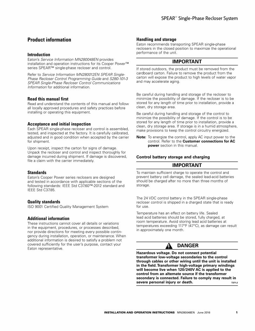
Product information
IntroductionEaton’s Service Information MN280048EN provides installation and operation instructions for its Cooper Power™ series SPEAR™ single-phase recloser and control.
Refer to Service Information MN280012EN SPEAR Single-Phase Recloser Control Programming Guide and S280-101-3 SPEAR Single-Phase Recloser Control Communications Information for additional information.
Read this manual firstRead and understand the contents of this manual and follow all locally approved procedures and safety practices before installing or operating this equipment.
Acceptance and initial inspectionEach SPEAR single-phase recloser and control is assembled, tested, and inspected at the factory. It is carefully calibrated, adjusted and in good condition when accepted by the carrier for shipment.
Upon receipt, inspect the carton for signs of damage. Unpack the recloser and control and inspect thoroughly for damage incurred during shipment. If damage is discovered, file a claim with the carrier immediately.
StandardsEaton’s Cooper Power series reclosers are designed and tested in accordance with applicable sections of the following standards: IEEE Std C37.60™-2012 standard and IEEE Std C37.85.
Quality standardsISO 9001 Certified Quality Management System
Additional informationThese instructions cannot cover all details or vari ations in the equipment, procedures, or processes described, nor provide directions for meeting every possible contin-gency during installation, operation, or maintenance. When additional information is desired to satisfy a problem not cov ered sufficiently for the user’s purpose, contact your Eaton representative.
Handling and storageEaton recommends transporting SPEAR single-phase reclosers in the closed position to maximize the operational performance of the unit.
IMPORTANTIf stored outdoors, the product must be removed from the cardboard carton. Failure to remove the product from the carton will expose the product to high levels of water vapor and may accelerate aging.
Be careful during handling and storage of the recloser to minimize the possibility of damage. If the recloser is to be stored for any length of time prior to installation, provide a clean, dry storage area.
Be careful during handling and storage of the control to minimize the possibility of damage. If the control is to be stored for any length of time prior to installation, provide a clean, dry storage area. If storage is in a humid atmosphere, make provisions to keep the control circuitry energized.
otee:N To energize the control, apply AC input power to the control. Refer to the Customer connections for AC power section in this manual.
Control battery storage and charging
IMPORTANTTo maintain sufficient charge to operate the control and prevent battery cell damage, the sealed lead-acid batteries should be charged after no more than three months of storage.
The 24 VDC control battery in the SPEAR single-phase recloser control is shipped in a charged state that is ready for use.
Temperature has an effect on battery life. Sealed lead acid batteries should be stored, fully charged, at room temperature. Avoid storing lead acid batteries at temperatures exceeding 117°F (47°C), as damage can result in approximately one month.
DANGERHazardous voltage . Do not connect potential transformer low-voltage secondaries to the control through cables or other wiring until the unit is installed in the field . Transformer high-voltage primary windings will become live when 120/240V AC is applied to the control from an alternate source if the transformer secondary is connected . Failure to comply may result in severe personal injury or death . T371 .2
2
SPEAR™ Single-Phase Recloser System
INSTALLATION AND OPERATION INSTRUCTIONS MN280048EN June 2016
WARNINGHazardous voltage . Before applying power to the control, confirm that male pins of the input power receptacle are electrically insulated to prevent unintentional contact with 120/240V AC voltage . Failure to do so may result in severe personal injury or death . T372 .1
IMPORTANTConnect the control battery before AC power is applied. The battery must be disconnected prior to shipping or storing the control.
To keep the battery charged, energize the control with AC power. See Customer connections for AC power. In addition, if power to the control is not possible a separate portable charger accessory is available. Catalog Number KA43ME7001 provides a 120 Volt battery charger to power individual batteries.
IMPORTANTTo avoid damage to the wiring or batteries, do not transport the control with the batteries installed.
otee:N When shipped from the factory, the battery will be placed on top of the control enclosure in the carton. The battery leads will be taped to the battery casing. Connect the battery plugs into the mating connectors to complete the battery circuit.
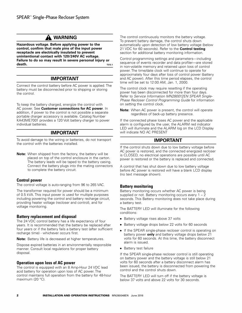
Control powerThe control voltage is auto-ranging from 96 to 265 VAC.
The transformer required for power should be a minimum of 0.5 kVA. This input power is used for multiple purposes including powering the control and battery recharge circuit, providing heater voltage (recloser and control), and for voltage monitoring.
Battery replacement and disposalThe 24 VDC control battery has a life expectancy of four years. It is recommended that the battery be replaced after four years or if the battery fails a battery test (after sufficient recharge time) - whichever occurs first.
otee:N Battery life is decreased at higher temperatures.
Dispose expired batteries in an environmentally responsible manner. Consult local regulations for proper battery disposal.
Operation upon loss of AC powerThe control is equipped with an 8 Amp-Hour 24 VDC lead acid battery for operation upon loss of AC power. The control maintains full operation from the battery for 48-hour maximum (20 °C).
The control continuously monitors the battery voltage. To prevent battery damage, the control shuts down automatically upon detection of low battery voltage (below 21 VDC for 60 seconds). Refer to the Control testing section for additional battery monitoring information.
Control programming settings and parameters—including sequence of events recorder and data profiler—are stored in non-volatile memory and retained upon loss of control power. The time/date clock will continue to operate for approximately four days after loss of control power (battery and AC power). After this time period elapses, the control time will be set to 12:00 AM, Jan. 1, 2000.
The control clock may require resetting if the operating power has been disconnected for more than four days. Refer to Service Information MN280012EN SPEAR Single-Phase Recloser Control Programming Guide for information on setting the control clock.
otee:N When AC power is present, the control will operate regardless of back-up battery presence.
If the connected phase loses AC power and the applicable alarm is configured by the user, the ALARM red indicator LED will illuminate and the ALARM log on the LCD Display will indicate NO AC PRESENT
IMPORTANTIf the control shuts down due to low battery voltage before AC power is restored, and the connected energized recloser is CLOSED, no electrical operations are possible until AC power is restored or the battery is replaced and connected.
A control that has shut down due to low battery voltage before AC power is restored will have a blank LCD display (no text message shown).
Battery monitoringBattery monitoring occurs whether AC power is being supplied or not. Battery monitoring occurs every 1 – 2 seconds. This Battery monitoring does not take place during a battery test.
The BATTERY LED will illuminate for the following conditions:
Battery voltage rises above 37 volts
Battery voltage drops below 22 volts for 60 seconds
If the SPEAR single-phase recloser control is operating on battery power only and battery voltage drops below 21 volts for 60 seconds. At this time, the battery disconnect alarm is issued.
Battery test failure
If the SPEAR single-phase recloser control is still operating on battery power and the battery voltage is still below 21 volts for 60 seconds after a battery disconnect alarm has been issued, the battery is disconnected from powering the control and the control shuts down.
The BATTERY LED will turn off if the battery voltage is below 37 volts and above 22 volts for 30 seconds.
3
SPEAR™ Single-Phase Recloser System
INSTALLATION AND OPERATION INSTRUCTIONS MN280048EN June 2016
ProView™ NXG softwareEaton’s Cooper Power series ProView™ NXG software is available for download from a link via the SPEAR Control product page at www.cooperpowercentral.com. In order to use the website it is necessary to register. Once registered, enter the site and navigate to the software page by clicking on the Software button in the black bar near the top of the page. Follow the links for downloading ProView NXG software. Refer to Service Information MN280012EN SPEAR Single-Phase Recloser Control Programming Guide for software download, installation and programming information.
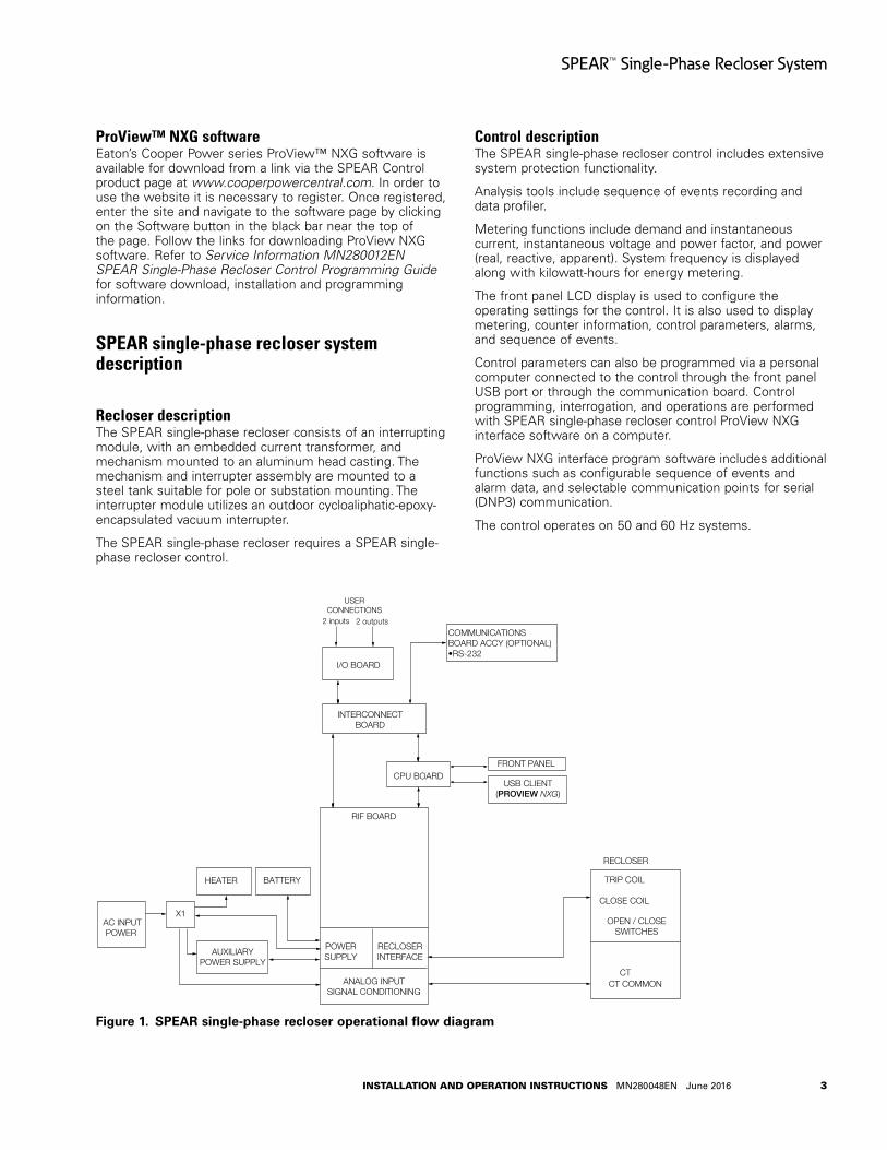
SPEAR single-phase recloser system description
Recloser descriptionThe SPEAR single-phase recloser consists of an interrupting module, with an embedded current transformer, and mechanism mounted to an aluminum head casting. The mechanism and interrupter assembly are mounted to a steel tank suitable for pole or substation mounting. The interrupter module utilizes an outdoor cycloaliphatic-epoxy-encapsulated vacuum interrupter.
The SPEAR single-phase recloser requires a SPEAR single-phase recloser control.
Control descriptionThe SPEAR single-phase recloser control includes extensive system protection functionality.
Analysis tools include sequence of events recording and data profiler.
Metering functions include demand and instantaneous current, instantaneous voltage and power factor, and power (real, reactive, apparent). System frequency is displayed along with kilowatt-hours for energy metering.
The front panel LCD display is used to configure the operating settings for the control. It is also used to display metering, counter information, control parameters, alarms, and sequence of events.
Control parameters can also be programmed via a personal computer connected to the control through the front panel USB port or through the communication board. Control programming, interrogation, and operations are performed with SPEAR single-phase recloser control ProView NXG interface software on a computer.
ProView NXG interface program software includes additional functions such as configurable sequence of events and alarm data, and selectable communication points for serial (DNP3) communication.
The control operates on 50 and 60 Hz systems.
Figure 1 .
TRIP COIL
CLOSE COIL
CT
OPEN / CLOSESWITCHES
CT COMMON
RECLOSER
AC INPUTPOWER
BATTERY
INTERCONNECTBOARD
I/O BOARD
FRONT PANEL
USB CLIENT(PROVIEW NXG)
USERCONNECTIONS
COMMUNICATIONSBOARD ACCY (OPTIONAL)•RS-232
2 inputs 2 outputs
CPU BOARD
RIF BOARD
POWERSUPPLY
RECLOSERINTERFACE
ANALOG INPUTSIGNAL CONDITIONING
X1
AUXILIARYPOWER SUPPLY
HEATER
SPEAR single-phase recloser operational flow diagram
4
SPEAR™ Single-Phase Recloser System
INSTALLATION AND OPERATION INSTRUCTIONS MN280048EN June 2016
Theory of operationA functional block diagram of the SPEAR single-phase recloser control is shown in Figure 1. Current sensing is provided by one current transformer located in the recloser and interfaced to the SPEAR single-phase recloser control via the control cable. This cable also supplies Trip, Close, and Recloser status, and provides isolation for reliable operation. Voltage for metering is connected to the control through the cabinet harness.
Line current flowing through the recloser is converted to a digital signal suitable for metering and fault current calculations. Data sampling occurs at a rate of 20 times per cycle. The control contains a data acquisition section that uses the acquired samples to compute the fundamental current and voltage for use in overcurrent protection, as well as current and voltage for metering functions. The current is calculated four times per cycle for overcurrent protection. The current only includes the fundamental frequency current and does not include harmonics.
When the phase current exceeds its programmed minimum-trip value and associated time-current-curve (TCC) timing, the control initiates the programmed sequence of recloser tripping and reclosing operations. If the fault is temporary, the control ceases to command recloser operations after a successful reclose, and the control resets to the start of its operating sequence after a preset time delay. If the fault is permanent, the control performs its complete programmed sequence of reclose commands and locks out with the recloser open. Once locked out, the control must be closed via the operator panel or SCADA communications. This resets the control to the start of the operating sequence.
The following chain of events occurs for an operating sequence of two trips to lockout (one trip on TCC1, one trip on TCC2):
1. The overcurrent signal is integrated with time on the selected curve for the first trip operation (TCC1) to produce the signal which energizes the trip circuit.
2. Energizing the trip circuit connects the supply to the trip coil to open the recloser.
3. Upon opening, the control starts timing on the first reclosing interval-delay time.
4. Upon expiration of this reclosing interval-delay, a closing signal is issued from the control, closing the recloser, and selecting the time-current characteristics for the second trip operation (TCC2).
5. If current remains above the minimum-trip level, the recloser will trip on TCC2 and lockout the recloser.
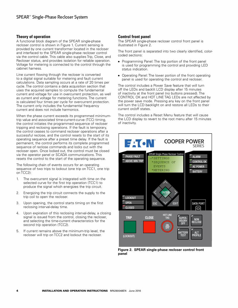
Control front panelThe SPEAR single-phase recloser control front panel is illustrated in Figure 2.
The front panel is separated into two clearly identified, color-coded sections:
Programming Panel: The top portion of the front panel is used for programming the control and providing LED status indication.
Operating Panel: The lower portion of the front operating panel is used for operating the control and recloser.
The control includes a Power Save feature that will turn off the LEDs and backlit LCD display after 15 minutes of inactivity at the front panel (no buttons pressed). The CONTROL OK and HOT LINE TAG LEDs are not affected by the power save mode. Pressing any key on the front panel will turn the LCD backlight on and restore all LEDs to their current on/off states.
The control includes a Reset Menu feature that will cause the LCD display to revert to the root menu after 15 minutes of inactivity.
Figure 2 .
DATA PORT
ENTER
EDITESC
BATTERYTEST
SUPER-VISORY
OFFNON
RECLOSE
HOT LINETAGTRIP
OFF
(LOCKOUT)
CLOSE
SPEAR Single-Phase Recloser Control
ON
ALTPROFILE
PHASE FAULT
ABOVE MIN TRIPALARM
CONTROL OK
AC POWER
BATTERY
LOCKOUT
OPEN
CLOSED
→*SETTINGS *SEQUENCE OF EVENTS *METERING
SPEAR single-phase recloser control front panel

5
SPEAR™ Single-Phase Recloser System
INSTALLATION AND OPERATION INSTRUCTIONS MN280048EN June 2016
Programming panel
CAUTIONEquipment misoperation . Use of the control front panel HMI may result in several combinations of settings, configurations, and customizations . The user must ensure that a proper combination is created and downloaded for the appropriate device application . G163 .0
The Programming panel has the following sections:
LCD display (Figure 3)The LCD display is a 4-line, 16-character display.
The keypad functionality is summarized as follows.
The (up) key can be used for the following tasks:
Scroll to the next item up on the current Menu level
If already at the first item of the current Menu level, return to the last item of the current Menu
When editing a selectable option parameter, scroll up to the next available option
Decrement the value of a digit (example: from 6 to 5)
Figure 3 .
DATA PORT
ENTER
EDITESC
BATTERYTEST
SUPER-VISORY
OFFNON
RECLOSE
HOT LINETAGTRIP
OFF
(LOCKOUT)
CLOSE
SPEAR Single-Phase Recloser Control
ON
ALTPROFILE
PHASE FAULT
ABOVE MIN TRIPALARM
CONTROL OK
AC POWER
BATTERY
LOCKOUT
OPEN
CLOSED
→*SETTINGS *SEQUENCE OF EVENTS *METERING
LCD display and keypad functionality
The (down) key can be used to complete the following tasks:
Scroll to the next item down on current Menu level
If scrolled past the last line of the current Menu level, return to the first line of the current Menu
When editing a Selectable Option Parameter, scroll down to the next available option
Increment the value of a digit (example: from 3 to 4)
The (left) key is used to go up one Menu level.
The (left) key is used to move left when editing parameters.
The (right) key is used to go down one Menu level.
The (right) key is used to move right when editing parameters.
The ESC (escape) key is used for the following tasks:
Go back one Menu level
Cancel Edit mode when editing settings without changing the value
The ENTER key is used for the following tasks:
Go down one Menu level
Confirm settings change in the Edit mode
Confirm resetting the Resettable Parameters
Confirm passwords
The EDIT key is used for the following tasks:
Enter the Edit mode to make a change.
Enter the Reset mode to reset the Resettable Parameter
Status indicator LEDsThe status indicator LEDs (Figure 4 and Figure 5) in the Programming section of the Operator Panel give instant information on the control and recloser status:
This information is indicated on the left side of the control: (Figure 4):
PHASE FAULT: This LED illuminates when the control issues an overcurrent trip signal while the phase current exceeds the programmed minimum trip value.
ABOVE MIN TRIP: This LED illuminates when the control detects that current is above the programmed minimum trip value.
LOCKOUT: This LED illuminates to indicate the control is in a locked out state, i.e. a reclosing sequence is not in progress. This LED does not indicate that the recloser is open.
WARNINGHazardous voltage . Do not rely on the open position of the yellow operating handle on the recloser or the OPEN or LOCKOUT LED indicators on the recloser control; it does not ensure that the line has been de-energized . Always establish a visible disconnect . Failure to follow proper safety practices can result in contact with high voltage, which will cause death or severe personal injury . G171 .0

6
SPEAR™ Single-Phase Recloser System
INSTALLATION AND OPERATION INSTRUCTIONS MN280048EN June 2016
Figure 4 .
DATA PORT
ENTER
EDITESC
BATTERYTEST
SUPER-VISORY
OFFNON
RECLOSE
HOT LINETAGTRIP
OFF
(LOCKOUT)
CLOSE
SPEAR Single-Phase Recloser Control
ON
ALTPROFILE
PHASE FAULT
ABOVE MIN TRIPALARM
CONTROL OK
AC POWER
BATTERY
LOCKOUT
OPEN
CLOSED
→*SETTINGS *SEQUENCE OF EVENTS *METERING
SPEAR single-phase recloser control status indicator LED (left side)
OPEN: This LED illuminates to indicate the recloser is in the open position.
CLOSED: This LED illuminates to indicate the recloser is in the closed position.
otee:N There are several conditions that will cause the alternate blinking of the control LOCKOUT, recloser OPEN, and recloser CLOSED LEDs: Failure to Trip, Failure to Close, Interrupter Malfunction, and 52a/b Disagreement.
The LED blinking pattern for these conditions is the control LOCKOUT LED and recloser CLOSED LED alternating with the recloser OPEN LED.
otee:N Reset Targets (under Counters menu) will clear the Interrupter Malfunction diagnostic. The alarm LED will remain illuminated as long as the alarm condition exists.
IMPORTANTThe CLOSED LED will blink and a countdown-to-close timer will appear on the LCD display when a delayed CLOSE is active. A CLOSE will occur when the manual close delay timer expires.
This information is indicated on the right side of the control: (Figure 5):
Figure 5 .
DATA PORT
ENTER
EDITESC
BATTERYTEST
SUPER-VISORY
OFFNON
RECLOSE
HOT LINETAGTRIP
OFF
(LOCKOUT)
CLOSE
SPEAR Single-Phase Recloser Control
ON
ALTPROFILE
PHASE FAULT
ABOVE MIN TRIPALARM
CONTROL OK
AC POWER
BATTERY
LOCKOUT
OPEN
CLOSED
→*SETTINGS *SEQUENCE OF EVENTS *METERING
SPEAR single-phase recloser control status indicator LED (right side)
ALARM: This LED illuminates to indicate an alarm condition exists. The LED will flash for unacknowledged alarms, and will continuously illuminate for acknowledged alarms that are still active. Refer to Service Information MN280012EN SPEAR Single-Phase Recloser Control Programming Guide for alarm list.
These Status Alarms are enabled by default:
AC Power present
Battery Disconnect
Battery Failure
Battery Trouble
Clock Not Set
Control Circuit Interrupted
Interrupter Malfunction
Recloser Closed: Failed to Trip
Recloser Open: Failed to Close
State Indeterminate Open and Closed
IMPORTANTTo enable or disable specific alarms, use the ProView NXG software to configure the alarms. Refer to Section 5e: Alarms in Service Information MN280012EN SPEAR Single-Phase Recloser Control Programming Guide. If alarms are not configured, the ALARM LED will not illuminate.
CAUTION Loss of protection . Reconfigure the user settings . When the CONTROL OK LED is flashing, control protection is disabled . User protection profile settings must be reconfigured to enable protection . Loss of protection can result in personal injury and equipment damage . T360 .1

7
SPEAR™ Single-Phase Recloser System
INSTALLATION AND OPERATION INSTRUCTIONS MN280048EN June 2016
CONTROL OK: This indicator illuminates to indicate that the control passed self-diagnostics and is capable of normal operation.
otee:N A flashing CONTROL OK LED indicates a problem with user settings. Default settings will be displayed under these circumstances, but protection has been disabled. User protection profile settings must be reconfigured to enable protection.
When the CONTROL OK LED is flashing, the following message appears on the LCD display upon power-up:
Protection Off. Change protec. setting. Use ESC to clear message.
As soon as the HMI goes into power save mode (inactivity for 15 minutes) the message will no longer display on the LCD, but the CONTROL OK LED will continue to flash to indicate protection is disabled.
AC POWER: This indicator is illuminated when the presence of AC input power to the control is sensed.
BATTERY: This LED illuminates to indicate battery voltage is low or the battery failed a battery test.
Data portThe DATA PORT section (Figure 6) on the front operating panel allows for direct connection to a personal computer.
Figure 6 .
DATA PORT
ENTER
EDITESC
BATTERYTEST
SUPER-VISORY
OFFNON
RECLOSE
HOT LINETAGTRIP
OFF
(LOCKOUT)
CLOSE
SPEAR Single-Phase Recloser Control
ON
ALTPROFILE
PHASE FAULT
ABOVE MIN TRIPALARM
CONTROL OK
AC POWER
BATTERY
LOCKOUT
OPEN
CLOSED
→*SETTINGS *SEQUENCE OF EVENTS *METERING
DATA PORT section
The USB data port is a client port used to communicate with the control from a personal computer. This port is used for accessing the control with ProView NXG application software. All settings, metering, alarms, and events are available from this port. The USB data port can be accessed either by user supplied USB cable, or purchased from the factory (part number KSPRC-66).
Operating panel
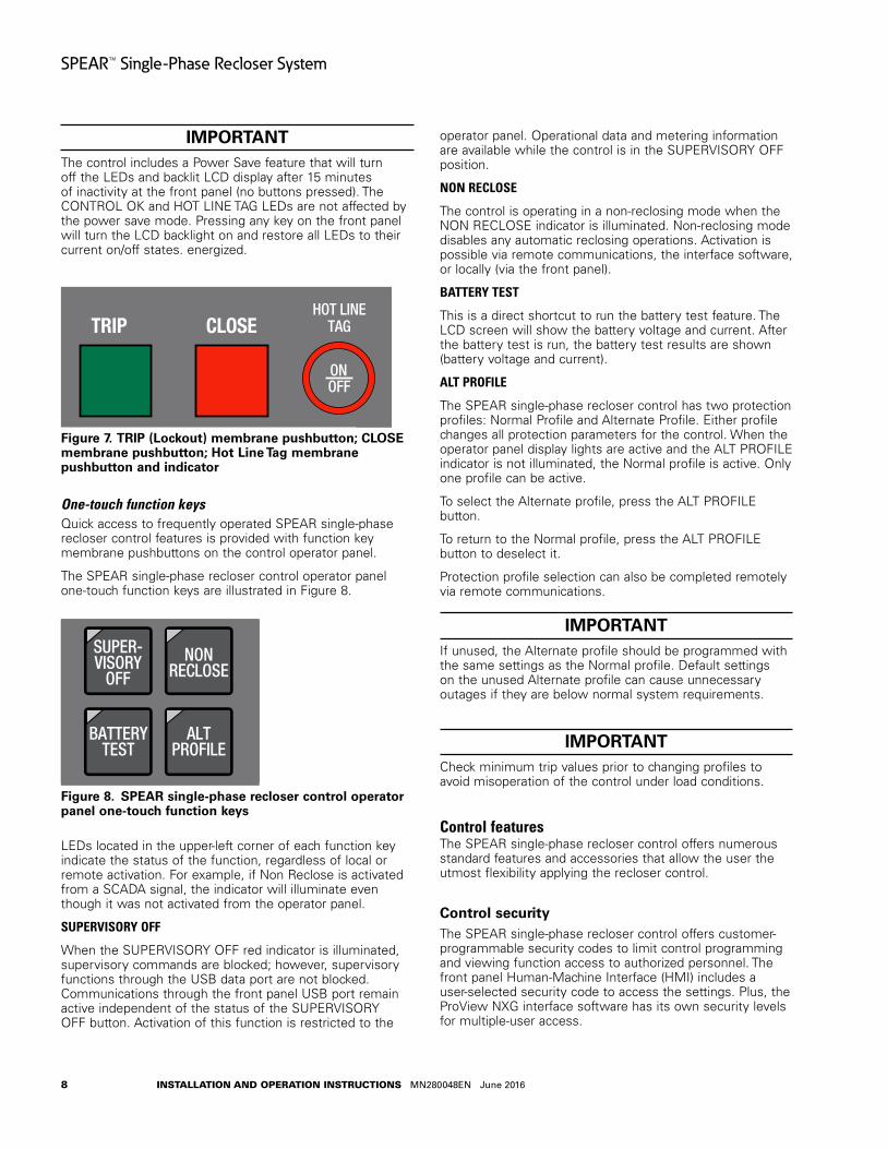
TRIP (lockout) membrane pushbuttonThe TRIP pushbutton (Figure 7) provides front-panel access to trip (lockout) the recloser. When pressed, the TRIP pushbutton opens the recloser and locks out the control. Control power is required for the TRIP button to issue a command to the recloser.
CLOSE membrane pushbuttonWhen pressed, the CLOSE pushbutton (Figure 7) returns the control to the initial or home sequence position, closing the recloser. The control is ready for the start of a new trip/close sequence.
otee:N Pressing the CLOSE pushbutton from the Lockout position initiates Cold Load Pickup (CLPU) protection, if the feature is enabled, and the recloser has been open longer than the CLPU minimum open time.
HOT LINE TAG ON/OFF membrane pushbutton and LED indicator
WARNINGHazardous voltage . Do not use Hot Line Tag as a substitute for a visible disconnect . Always establish a visible disconnect prior to performing any work requiring a de-energized line . Failure to comply may cause death, severe personal injury, or equipment damage . T276 .0
IMPORTANTHot Line Tag activation does not cause the recloser to trip open. It only prevents the recloser from closing.
IMPORTANTHot Line Tag is intended solely for live-line work applications, such as maintenance, repairs or improvements to the distribution system, that occur while the line remains energized.
Hot Line Tag is provided for live-line work applications. All closing operations are disabled when the Hot Line Tag feature is activated.
Hot Line Tag prevents all closing attempts from the control and shifts protection to one trip-to-lockout on the composite curve of the Hot Line Tag definite time and the TCC1 curve (whichever is faster). Hot Line Tag takes precedence over Cold Load Pickup, Non-Reclosing, and Fast Trips Disabled.
Hot Line Tag is activated from either the operator panel membrane pushbutton, local, or remote. All sources must be off to de-activate Hot Line Tag.
To activate the function from the operator panel, press the HOT LINE TAG membrane pushbutton. See Figure 7. The LED indicator circle that surrounds the button illuminates when the function is active.
The Hot Line Tag function may only be reset by the source which initiates it. For example, if Hot Line Tag is activated at the operator panel, the reset function is only possible at the operator panel.
8
SPEAR™ Single-Phase Recloser System
INSTALLATION AND OPERATION INSTRUCTIONS MN280048EN June 2016
IMPORTANTThe control includes a Power Save feature that will turn off the LEDs and backlit LCD display after 15 minutes of inactivity at the front panel (no buttons pressed). The CONTROL OK and HOT LINE TAG LEDs are not affected by the power save mode. Pressing any key on the front panel will turn the LCD backlight on and restore all LEDs to their current on/off states. energized.
Figure 7 .
DATA PORT
ENTER
EDITESC
BATTERYTEST
SUPER-VISORY
OFFNON
RECLOSE
HOT LINETAGTRIP
OFF
(LOCKOUT)
CLOSE
SPEAR Single-Phase Recloser Control
ON
ALTPROFILE
PHASE FAULT
ABOVE MIN TRIPALARM
CONTROL OK
AC POWER
BATTERY
LOCKOUT
OPEN
CLOSED
→*SETTINGS *SEQUENCE OF EVENTS *METERING
TRIP (Lockout) membrane pushbutton; CLOSE membrane pushbutton; Hot Line Tag membrane pushbutton and indicator
One-touch function keysQuick access to frequently operated SPEAR single-phase recloser control features is provided with function key membrane pushbuttons on the control operator panel.
The SPEAR single-phase recloser control operator panel one-touch function keys are illustrated in Figure 8.
Figure 8 .
DATA PORT
ENTER
EDITESC
BATTERYTEST
SUPER-VISORY
OFFNON
RECLOSE
HOT LINETAGTRIP
OFF
(LOCKOUT)
CLOSE
SPEAR Single-Phase Recloser Control
ON
ALTPROFILE
PHASE FAULT
ABOVE MIN TRIPALARM
CONTROL OK
AC POWER
BATTERY
LOCKOUT
OPEN
CLOSED
→*SETTINGS *SEQUENCE OF EVENTS *METERING
SPEAR single-phase recloser control operator panel one-touch function keys
LEDs located in the upper-left corner of each function key indicate the status of the function, regardless of local or remote activation. For example, if Non Reclose is activated from a SCADA signal, the indicator will illuminate even though it was not activated from the operator panel.
SUPERVISORY OFF
When the SUPERVISORY OFF red indicator is illuminated, supervisory commands are blocked; however, supervisory functions through the USB data port are not blocked. Communications through the front panel USB port remain active independent of the status of the SUPERVISORY OFF button. Activation of this function is restricted to the
operator panel. Operational data and metering information are available while the control is in the SUPERVISORY OFF position.
NON RECLOSE
The control is operating in a non-reclosing mode when the NON RECLOSE indicator is illuminated. Non-reclosing mode disables any automatic reclosing operations. Activation is possible via remote communications, the interface software, or locally (via the front panel).
BATTERY TEST
This is a direct shortcut to run the battery test feature. The LCD screen will show the battery voltage and current. After the battery test is run, the battery test results are shown (battery voltage and current).
ALT PROFILE
The SPEAR single-phase recloser control has two protection profiles: Normal Profile and Alternate Profile. Either profile changes all protection parameters for the control. When the operator panel display lights are active and the ALT PROFILE indicator is not illuminated, the Normal profile is active. Only one profile can be active.
To select the Alternate profile, press the ALT PROFILE button.
To return to the Normal profile, press the ALT PROFILE button to deselect it.
Protection profile selection can also be completed remotely via remote communications.
IMPORTANTIf unused, the Alternate profile should be programmed with the same settings as the Normal profile. Default settings on the unused Alternate profile can cause unnecessary outages if they are below normal system requirements.
IMPORTANTCheck minimum trip values prior to changing profiles to avoid misoperation of the control under load conditions.
Control featuresThe SPEAR single-phase recloser control offers numerous standard features and accessories that allow the user the utmost flexibility applying the recloser control.
Control securityThe SPEAR single-phase recloser control offers customer-programmable security codes to limit control programming and viewing function access to authorized personnel. The front panel Human-Machine Interface (HMI) includes a user-selected security code to access the settings. Plus, the ProView NXG interface software has its own security levels for multiple-user access.

9
SPEAR™ Single-Phase Recloser System
INSTALLATION AND OPERATION INSTRUCTIONS MN280048EN June 2016
Refer to Service Information MN280012EN SPEAR Single-Phase Recloser Control Programming Guide for additional information regarding how to set and change passwords.
Password recoveryIf your password is lost, contact your Eaton representative.
Protection profilesTwo protection profiles capable of fully specifying control operation are standard in the control. Each protection profile includes the following as a minimum:
Overcurrent Protection
Hot Line Tag Functionality
Sequence Coordination
Operation Settings
Time current curvesTime-current curves are available for both fast and delayed operations for phase protection. Each time-current curve is selected from a list of pre-defined curves which can be further customized by the user.
The time-current curves include the following modifications for phase and ground protection:
Time Multiplier with a range of 0.1 to 25.
Time Adder with a range of 0 to 30 seconds in .01 second increments.
Minimum Response Time with a range of 0.01 to 1 seconds.
High Current Trip multiplier with a range of 1 to 32 multipliers.
High Current Trip Time Delay with a range of 0.01 to .150 second.
Sequence coordinationSequence Coordination eliminates nuisance tripping through trip coordination. It allows the control to step through selected operations in the operating sequence without tripping. The number of Sequence Coordination advances is programmable from one to three operations to provide trip coordination with a downline recloser. This feature is independently programmable for each protection profile.
Cold load pickupThe control includes a Cold Load Pickup feature to prevent the control from tripping due to inrush while energizing non-fault system loads. This feature has independently programmable minimum trip value, time-current curve, reclose interval, and number of operations to lockout for each protection profile. Cold Load Pickup also includes TCC Multipliers, TCC Adders, Minimum Response Time, and High Current Lockout. Also, direct values, not multiples of minimum trip, are provided for high current lockout. When enabled, Cold Load Pickup is active for any close operation.
Fast trips disabledThe control includes a Fast Trips Disabled feature to modify protection, so that all trip operations use the programmed Fast Trips Disabled (FTD) TCC. This feature is independently selectable for each protection profile. All trip operations will time on FTD TCC. Typically, TCC1 is fast and TCC2 is delayed. So, as an example, the control will change its sequence from 2 fast and 2 delayed operations to 2 operations on FTD TCC when Fast Trips Disabled is enabled.
High current tripThe High Current Trip (HCT) feature will trip at a selected multiple of phase minimum trip. The HCT definite time is programmed independently from the normal TCCs. This feature is independently selectable for each protection profile.
High current lockoutThe High Current Lockout (HCL) feature will automatically lockout the control on the selected operation when current exceeds a programmable level. The active number of selectable operations to lockout is independently selectable for each protection profile.
Thermostatically controlled heaterThe control has a standard thermostatically controlled heater for humidity control. The heater is powered from input voltage.
MeteringThe control provides instantaneous and/or demand metering with programmable integration intervals for the following functions:
Real, reactive, and apparent power including power direction
Demand current and power
Instantaneous current
Instantaneous voltage
Instantaneous frequency
Instantaneous power factor
Sequence of events recorderThe SPEAR single-phase recloser control contains capabilities to perform Sequence of Events with time-stamping.
Factory-defined event types include:
Phase Trip and Lockout
Local Trip/Lockout (Front Op. Panel)
Frequency Trip
Ext. Close Request
Phase Fault
Overcurrent reset

10
SPEAR™ Single-Phase Recloser System
INSTALLATION AND OPERATION INSTRUCTIONS MN280048EN June 2016
otee:N The user can select additional event types from alarm configuration.
The Event Recorder maintains a minimum of 1000 events. The most recent 50 events (event name and timestamp) are viewable on the front panel LCD display. Refer to Service Information MN280012EN SPEAR Single-Phase Recloser Control Programming Guide for additional information.
Recloser duty monitorThe SPEAR single-phase recloser control software is equipped with a Recloser Interrupting Duty Monitor. The Duty Monitor accumulates the summation of Current1.5 for all interrupted currents. This feature permits programmable entries to preset the duty of an existing recloser. The recloser duty monitor displays interrupting duty in percent of duty used. If the duty cycle monitor exceeds 100%, the recloser should be examined for maintenance.
Contact I/O module optionThe SPEAR single-phase recloser control comes pre-configured with two sets of Input and Output contacts. This feature permits connection of contact type input devices (switches, relays) and discrete indicating devices (relays, LEDs, lamps) to the SPEAR single-phase recloser control to affect local discrete input/output.
Data profilerA fully configurable data profiler is available which allows the user to collect information of the selected inputs by sampling data at user-programmable intervals. These time-stamped values can then be viewed to determine weekly load profiles, hourly voltage and/or current fluctuations, battery voltage and current, and frequency. The number of days of information the data profiler can provide depends upon configuration parameters.
Refer to Service Information MN280012EN SPEAR Single-Phase Recloser Control Programming Guide for additional information.
Manual close time delayManual Close Time Delay provides a delay from the time that the manual CLOSE button is pushed to the time the manual close operation is performed.
The delay is programmable from 0 to 60 seconds in 1 second increments. A programmed delay value can be overridden for immediate closing by pressing the CLOSE button a second time.
An active Manual Close Time Delay can be canceled by pressing the TRIP/LOCKOUT button.
The default setting has the feature disabled (0 seconds).
The CLOSED LED blinks to indicate a close delay is active and a countdown-to-close timer will appear on the LCD display.
Communications
Communication portsThe SPEAR single-phase recloser control has a front panel configuration data port and provisions for one optional side-panel communication port (Figure 9).
The front panel configuration data port is described in the Operating panel section of this manual.
There is one standard USB port (one client), as well as one communication accessory RS-232.
Communication protocolsOne native communication protocol is available for the SPEAR single-phase recloser control, which is DNP3 Serial.
The DNP3 Serial communication protocol can be configured by the user with the ProView NXG application software.
The user can simultaneously communicate to the SPEAR single-phase recloser control using both the front panel data port and the side panel communication port.
Control informationControl information includes firmware identification by catalog number and name, date code, and ProView NXG release number. Control information is available through the CONTROL sub-menu under DIAGNOSTICS menu on the front panel (Figure 3).
Control side panelThe control side panel is easily accessible when the wingpanel of the control cabinet is opened.
Figure 9 .
FRONT VIEW(DOOR REMOVED)
BOTTOM VIEW
FRONT VIEW(WITH CONTROL AND DOOR
REMOVED FOR CLARITY)
RIGHT SIDE VIEW
BACK VIEW
MODULE SIDE VIEW
FEMALERECEPTACLE
FOR RECLOSERCONTROL CABLE
INPUT RECEPTACLE
FOR RADIOANTENNARECEPTACLES
LATCHES WITHPADLOCK
PROVISIONS
1.13LIFTING LUG
10.63
MOUNTINGCHANNELS
1.129.84
PROVISIONS FORUP TO 5/8" MOUNTINGHARDWARE
GROUND LUG FOR#4 TO #14 SOLID ORSTRANDED WIRE
12.01
VENT OPENINGS
6.00
22.60
1.69
20.87
17.72
1.46
.87
POWER SUPPLY
BATTERY
OPTIONAL RS-232COMMUNICATIONPORT
CONTACT I/OMODULE
CONTROL MODULE
13.15
11.75
SHIELD WIRECONNECTION
SPEAR single-phase recloser control communication port

11
SPEAR™ Single-Phase Recloser System
INSTALLATION AND OPERATION INSTRUCTIONS MN280048EN June 2016
Ratings and specifications
Check recloser ratings prior to installationThe recloser must be applied within its specified ratings. Check data plate ratings and compare with the system characteristics at the point of application prior to installation. Tables 1–4 list the ratings and specifications for the SPEAR single-phase recloser.
Table 1 . Voltage and current ratings
Rating 15-8-400 15-12-630 15-12-800 27-8-400 27-12-630 27-12-800 38-8-400 38-12-630 38-12-800
Maximum Design Voltage (kV) 15.5 15.5 15.5 27.0 27.0 27.0 38.0 38.0 38.0Nominal Operating Voltage (kV) 14.4 14.4 14.4 24.9 24.9 24.9 34.5 34.5 34.5Basic Insulation Level (BIL*) (kV) 110 110 110 125 125 125 170 170 17060 Hertz Withstand Voltage (kV)
Dry, one minute
Wet, ten seconds
50
45
50
45
50
45
60
50
60
50
60
50
70
60
70
60
70
60Max RIV at 1.0 MHz
9.4 kV (μV)
16.4 kV (μV)
23.0 kV (μV)
100 100 100
100 100 100
100 100 100Continuous Current Ratings (A) 400 630 800 400 630 800 400 630 800Sym. Interrupting Current (A) 8,000 12,500 12,500 8,000 12,500 12,500 8,000 12,500 12,500Overload Capability
125% – 8 Hours (A)
150% – 4 Hours (A)
500
600
788
945
None
–
500
600
788
945
None
–
500
600
788
945
None
–Cable Charging Current (A) 10 10 10 25 25 25 40 40 40Line Charging Current (A) 2 2 2 5 5 5 5 5 5Three-Second Current, Sym. (A) 8,000 12,500 12,500 8,000 12,500 12,500 8,000 12,500 12,500*Extended BIL option available on 15.5 kV and 27 kV products.
otee:N The SPEAR single-phase recloser incorporates a tank heater which is configured for either 120 or 240 VAC. Refer to the Tank and Heater Options section in Catalog Data CA280001EN SPEAR™ single-phase recloser system for additional information.
Table 2 . Mechanical lifeMinimum Operations 10,000
Table 3 . Mass (weight) for SPEAR single-phase recloserRecloser 15 kV 27 kV 38 kVlbs (kg) 114 (52) 118 (54) 122 (56)
Table 4 . Duty cyclePercent of Maximum Circuit Interrupting Rating
Minimum X/R Ratio
Number of Unit Operations at 12.5 kA
15-20 4 8845-55 8 11290-100 17 32
Total 232
12
SPEAR™ Single-Phase Recloser System
INSTALLATION AND OPERATION INSTRUCTIONS MN280048EN June 2016
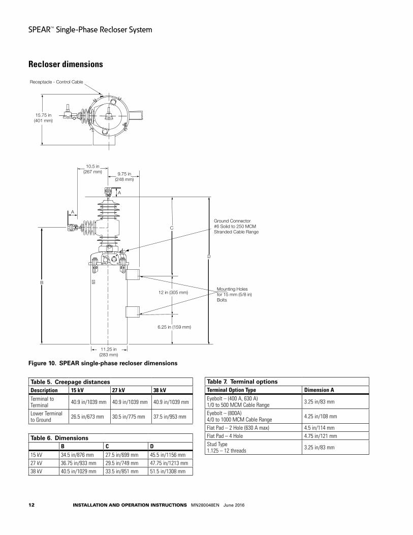
Recloser dimensions
Figure 10 .
CLOSED
15.75 in(401 mm)
Receptacle - Control Cable
10.5 in(267 mm) 9.75 in
(248 mm)
11.25 in(283 mm)
6.25 in (159 mm)
12 in (305 mm)
Ground Connector#6 Solid to 250 MCMStranded Cable Range
Mounting Holesfor 15 mm (5/8 in)Bolts
A
A
B
C
D
SPEAR single-phase recloser dimensions
Table 5 . Creepage distancesDescription 15 kV 27 kV 38 kVTerminal to Terminal 40.9 in/1039 mm 40.9 in/1039 mm 40.9 in/1039 mm
Lower Terminal to Ground 26.5 in/673 mm 30.5 in/775 mm 37.5 in/953 mm
Table 6 . DimensionsB C D
15 kV 34.5 in/876 mm 27.5 in/699 mm 45.5 in/1156 mm27 kV 36.75 in/933 mm 29.5 in/749 mm 47.75 in/1213 mm38 kV 40.5 in/1029 mm 33.5 in/851 mm 51.5 in/1308 mm
Table 7 . Terminal optionsTerminal Option Type Dimension AEyebolt – (400 A, 630 A) 1/0 to 500 MCM Cable Range 3.25 in/83 mm
Eyebolt – (800A) 4/0 to 1000 MCM Cable Range 4.25 in/108 mm
Flat Pad – 2 Hole (630 A max) 4.5 in/114 mmFlat Pad – 4 Hole 4.75 in/121 mmStud Type 1.125 – 12 threads 3.25 in/83 mm
13
SPEAR™ Single-Phase Recloser System
INSTALLATION AND OPERATION INSTRUCTIONS MN280048EN June 2016
Recloser installation procedure
WARNINGThis equipment is not intended to protect human life . Follow all locally approved procedures and safety practices when installing or operating this equipment . Failure to comply can result in death, severe personal injury, and equipment damage . G102 .1
WARNINGHazardous voltage . Always use a hotstick when working with this equipment . Failure to do so could result in contact with high voltage, which will cause death or severe personal injury . G108 .1
All reclosers are carefully tested and adjusted at the factory to operate according to published data. Well-equipped test facilities, detailed testing procedures, and thoroughly trained personnel assure accurately calibrated equipment. Each recloser leaves the factory ready for installation—pending completion of the steps in this procedure.
Eaton recommends transporting SPEAR single-phase reclosers in the closed position to maximize the operational performance of the unit.
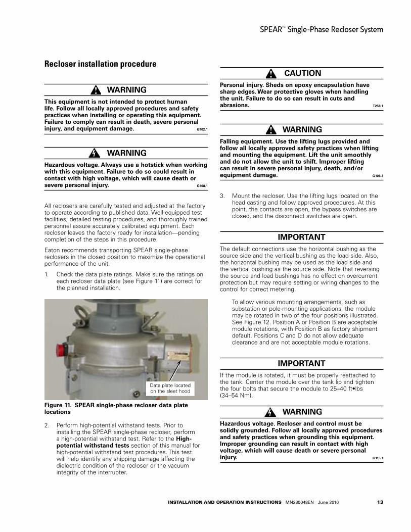
1. Check the data plate ratings. Make sure the ratings on each recloser data plate (see Figure 11) are correct for the planned installation.
Figure 11 .
Data plate located on the sleet hood
SPEAR single-phase recloser data plate locations
2. Perform high-potential withstand tests. Prior to installing the SPEAR single-phase recloser, perform a high-potential withstand test. Refer to the High-potential withstand tests section of this manual for high-potential withstand test procedures. This test will help identify any shipping damage affecting the dielectric condition of the recloser or the vacuum integrity of the interrupter.
CAUTIONPersonal injury . Sheds on epoxy encapsulation have sharp edges . Wear protective gloves when handling the unit . Failure to do so can result in cuts and abrasions . T258 .1
WARNINGFalling equipment . Use the lifting lugs provided and follow all locally approved safety practices when lifting and mounting the equipment . Lift the unit smoothly and do not allow the unit to shift . Improper lifting can result in severe personal injury, death, and/or equipment damage . G106 .3
3. Mount the recloser. Use the lifting lugs located on the head casting and follow approved procedures. At this point, the contacts are open, the bypass switches are closed, and the disconnect switches are open.
IMPORTANTThe default connections use the horizontal bushing as the source side and the vertical bushing as the load side. Also, the horizontal bushing may be used as the load side and the vertical bushing as the source side. Note that reversing the source and load bushings has no effect on overcurrent protection but may require setting or wiring changes to the control for correct metering.
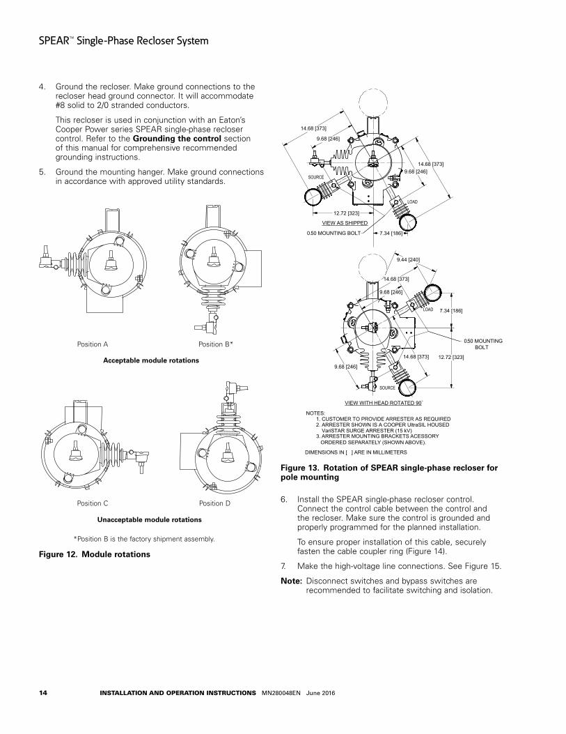
To allow various mounting arrangements, such as substation or pole-mounting applications, the module may be rotated in two of the four positions illustrated. See Figure 12. Position A or Position B are acceptable module rotations, with Position B as factory shipment default. Positions C and D do not allow adequate clearance and are not acceptable module rotations.
IMPORTANTIf the module is rotated, it must be properly reattached to the tank. Center the module over the tank lip and tighten the four bolts that secure the module to 25–40 ft•lbs (34–54 Nm).
WARNINGHazardous voltage . Recloser and control must be solidly grounded . Follow all locally approved procedures and safety practices when grounding this equipment . Improper grounding can result in contact with high voltage, which will cause death or severe personal injury . G115 .1
14
SPEAR™ Single-Phase Recloser System
INSTALLATION AND OPERATION INSTRUCTIONS MN280048EN June 2016
4. Ground the recloser. Make ground connections to the recloser head ground connector. It will accommodate #8 solid to 2/0 stranded conductors.
This recloser is used in conjunction with an Eaton’s Cooper Power series SPEAR single-phase recloser control. Refer to the Grounding the control section of this manual for comprehensive recommended grounding instructions.
5. Ground the mounting hanger. Make ground connections in accordance with approved utility standards.
Figure 12 .
Acceptable module rotations
Unacceptable module rotations
Position A Position B*
Position C Position D
*Position B is the factory shipment assembly.
Module rotations
Figure 13 .
SOURCE
LOAD
VIEW AS SHIPPED
LOAD
SOURCE
VIEW WITH HEAD ROTATED 90
NOTES: 1. CUSTOMER TO PROVIDE ARRESTER AS REQUIRED
.
2. ARRESTER SHOWN IS A COOPER UltraSIL HOUSED VariSTAR SURGE ARRESTER (15 kV)
14.68 [373]
14.68 [373]
12.72 [323]
7.34 [186]
9.68 [246]
9.68 [246]
0.50 MOUNTING BOLT
9.44 [240]
14.68 [373]
9.68 [246]
7.34 [186]
12.72 [323]
9.68 [246]
14.68 [373]
0.50 MOUNTINGBOLT
DIMENSIONS IN [ ] ARE IN MILLIMETERS
o
3. ARRESTER MOUNTING BRACKETS ACESSORY ORDERED SEPARATELY (SHOWN ABOVE).
Rotation of SPEAR single-phase recloser for pole mounting
6. Install the SPEAR single-phase recloser control. Connect the control cable between the control and the recloser. Make sure the control is grounded and properly programmed for the planned installation.
To ensure proper installation of this cable, securely fasten the cable coupler ring (Figure 14).
7. Make the high-voltage line connections. See Figure 15.
otee:N Disconnect switches and bypass switches are recommended to facilitate switching and isolation.

15
SPEAR™ Single-Phase Recloser System
INSTALLATION AND OPERATION INSTRUCTIONS MN280048EN June 2016
Figure 14 . Cable with cable coupler ring
A. Provide surge protection to both sides of the recloser.
otee:N The horizontal bushing is the source side and the vertical bushing is the load side. See Figure 16.
B. Connect high-voltage lines to recloser bushing terminals. The recommended torque value for bushing terminal-to-line connection is 45-50 ft•lbs.
Refer to Figure 16 for terminal identification of the SPEAR single-phase recloser.
Terminal connection to only copper conductors is recommended.
CAUTIONEquipment damage . Do not adjust or rotate bushing terminals without first removing power line leads and loosening pinch bolt to release clamp tension . Failure to remove tension between the clamp and the interrupter stud prior to rotating the terminal will damage the encapsulated interrupter assembly resulting in equipment damage . T347 .0
CAUTIONEquipment damage may occur if torque values are exceeded . T370 .0
To rotate a flat-pad or eyebolt bushing terminal prior to connecting power line leads, loosen the pinch bolt on the terminals. After rotating the terminal, retighten the pinch bolt as follows: torque 3/8-16 pinch bolts to 15–17 ft•lbs (20–23 Nm); torque 1/2-13 pinch bolts to 29–31 ft•lbs (39–42 Nm).
Figure 15 .
SurgeArrester
BypassSwitch
SurgeArrester
Recloser
Connection diagram showing complete surge protection with bypass and disconenct switches
Figure 16 .
Source
Load
Terminal identification of SPEAR single-phase recloser
8. Close source and load disconnect switches.
9. Close recloser via control signal.
10. Open bypass switches.

16
SPEAR™ Single-Phase Recloser System
INSTALLATION AND OPERATION INSTRUCTIONS MN280048EN June 2016
Removing recloser from service
WARNINGHazardous voltage . Always use a hotstick when working with this equipment . Failure to do so could result in contact with high voltage, which will cause death or severe personal injury . G108 .1
WARNINGHazardous voltage . Do not rely on the open position of the yellow operating handle on the recloser or the OPEN or LOCKOUT LED indicators on the recloser control; it does not ensure that the line has been de-energized . Always establish a visible disconnect . Failure to follow proper safety practices can result in contact with high voltage, which will cause death or severe personal injury . G171 .0
1. Close bypass switches.
2. Pull down the yellow operating handle with a hotstick. The yellow operating handle is located under the recloser sleet hood.
The control will sense that the recloser is open.
CAUTIONEquipment misoperation . Disconnect all control power sources prior to disconnecting or reconnecting the control cable from the control . Failure to comply can result in recloser misoperation at the time of disconnection or reconnection of the control cable to the control . T311 .1
3. Open the source and load disconnect switches.
4. Remove the control AC sensing and power connections from the control using a separate disconnect switch.
5. Disconnect the control battery.
IMPORTANTDisconnect switches for AC sensing and power connections are necessary to isolate the control for testing and servicing.
CAUTIONHazardous voltage . Open CT secondaries can generate high voltages . Contact with CT pins of the disconnected cable can cause electric shock and may result in personal injury . Open recloser contacts and open disconnect switches before disconnecting control cable . T204 .3
CAUTIONHazardous voltage . Cable conductors attached to controls will remain at 53V DC and 120/240V AC potential while connected to the control . Contact with any pins at the end of the cable directly or indirectly connected to a control can result in personal injury or equipment damage . Disconnect battery and external power sources in the control then remove control cable at control end before disconnecting from recloser end . T312 .3
6. Disconnect the control cable from the recloser.
7. Follow standard utility procedures regarding removal of recloser from service.
otee:N Eaton recommends transporting SPEAR single-phase reclosers in the closed position to maximize the operational performance of the unit.

17
SPEAR™ Single-Phase Recloser System
INSTALLATION AND OPERATION INSTRUCTIONS MN280048EN June 2016
Recloser operation
WARNINGThis equipment is not intended to protect human life . Follow all locally approved procedures and safety practices when installing or operating this equipment . Failure to comply can result in death, severe personal injury, and equipment damage . G102 .1
WARNINGHazardous voltage . Do not rely on the open position of the yellow operating handle or the contact position indicator; it does not ensure that the line has been de-energized . Always establish a visible disconnect . Failure to follow proper safety practices can result in contact with high voltage, which will cause death or severe personal injury . G114 .1
A current transformer senses line current from the SPEAR single-phase recloser and inputs this information to the SPEAR single-phase recloser control. The recloser responds to trip and close commands from the control, per the settings programmed in the control.
Vacuum interrupterArc interruption takes place within the sealed vacuum interrupter. Eaton’s Cooper Power series vacuum interrupters employ axial-magnetic field contacts. Slots are machined into the contact support structure producing a magnetic field along the axis of the interrupter. This axial-magnetic field keeps the arc in an easier-to-interrupt diffuse mode, resulting in less power in the arc that needs to be dissipated, resulting in extended operating duty.
Mechanism tripping and closingThe SPEAR single-phase recloser utilizes a magnetic actuator for fast, efficient latching. A rare-earth neodymium magnet provides latching forces in excess of 240 pounds, eliminating the need for mechanical latches.
While in the closed position, the magnetic field established by the magnet is coupled with the iron assembly to provide a latching force for the movable plunger. The magnetic force is concentrated at the plunger-assembly interface and provides the latching force required to keep the mechanism closed. The assembly also houses the trip and close coils that provide the energy to operate the mechanism.
To open the main contacts, the trip coil is pulsed with electrical current, which cancels the magnetic field. A compression spring in the center of the coil moves the plunger assembly to the open position. As the plunger moves, the magnetic field strength decreases as the air gap increases, due to the difference in the relative permeability
of free space and the ferrous plunger. Once in the open position, the compression spring keeps the unit open.
A trip and close capacitor stores the necessary energy for operating the recloser. As a result, trip energy is available following any close operation. This capacitor is charged by the control nominal 24 V battery and/or power supply.
Manual operation of energized recloser
WARNINGHazardous voltage . Do not rely on the open position of the yellow operating handle; it does not ensure that the line has been de-energized . Always establish a visible disconnect . Failure to follow proper safety practices can result in contact with high voltage, which will cause death or severe personal injury . G116 .0
WARNINGHazardous voltage . Always use a hotstick when working with this equipment . Failure to do so could result in contact with high voltage, which will cause death or severe personal injury . G108 .1
The yellow manual operating handle on the SPEAR single-phase recloser is used to open and lock out the recloser and disable the electrical and supervisory closing.
The manual operating handle is designed to be operated with a hotstick. See Figure 17. Pulling down the handle trips and locks open the main contacts of the recloser.
Contact position is indicated by the OPEN flag of the contact position indicator. The yellow operating handle will remain down in the OPEN position and not return upward under the sleet hood.
otee:N When the recloser electronically operates to lockout, the yellow operating handle will not drop down from under the sleet hood. The yellow operating handle remains in the OPEN position only after manual operations are performed.
The yellow operating handle must be returned up to the CLOSED position for the recloser to respond to a close signal from the SPEAR single-phase recloser control. All close operations are initiated by the control.

18
SPEAR™ Single-Phase Recloser System
INSTALLATION AND OPERATION INSTRUCTIONS MN280048EN June 2016
Lockout indicationLockout is indicated by the SPEAR single-phase recloser control.
otee:N When the recloser is locked out, the yellow manual operating handle will not drop down from under the sleet hood.
Automatic operationThe SPEAR single-phase recloser, in the CLOSED position, operates automatically per the control-programmed settings.
Contact position indicator
IMPORTANTPushing the yellow operating handle to the CLOSED position will not close the recloser. All close operations are initiated by the SPEAR single-phase recloser control.
Located on the outboard side of the sleet hood, this indicator displays the word OPEN (Green) when the recloser contacts are open and CLOSED (Red) when the recloser contacts are closed. See Figure 17.
Operations counterA four-digit mechanical counter, located under the sleet hood, cumulatively records each time the recloser operates. See Figure 17.
Figure 17 .
Manual open/close operating handle
Four-digit operations counter (underneath)
OPEN/CLOSED contact position indicator
SPEAR single-phase recloser operating lever and indicators
Control installation procedure
Initial programming prior to installation
CAUTION Equipment misoperation . Do not connect this control to an energized recloser until all control settings have been properly programmed and verified . Refer to the programming information for this control . Failure to comply can result in control and recloser misoperation, equipment damage, and personal injury . G110 .3
CAUTION Loss of protection . Reconfigure the user settings . When the CONTROL OK LED is flashing, control protection is disabled . User protection profile settings must be reconfigured to enable protection . Loss of protection can result in personal injury and equipment damage . T360 .1
CAUTIONEquipment misoperation . Check minimum trip values prior to changing an alternate profile . Failure to do so may cause misoperation of the recloser under load conditions . T290 .1
IMPORTANTProgram all protection profiles. If unused, the alternate profile should be programmed with the same settings as the Normal profile. Default settings on the unused alternate profile can cause unnecessary outages if they are below normal system requirements.
The control must be programmed with all necessary operating settings, all alternate profiles, parameters, and alarms prior to operation with an energized recloser.
otee:N Initial programming of the control is the responsibility of a qualified technician or engineer familiar with control functions and programming parameters required for the specific recloser installation.
otee:N A flashing CONTROL OK LED indicates a problem with user settings. Default settings will be displayed under these circumstances, but protection has been disabled. User protection profile settings must be reconfigured to enable protection.

19
SPEAR™ Single-Phase Recloser System
INSTALLATION AND OPERATION INSTRUCTIONS MN280048EN June 2016
When the CONTROL OK LED is flashing, the following message appears on the LCD display upon power-up:
Protection Off. Change protec. setting. Use ESC to clear message.
As soon as the HMI goes into power save mode (inactivity for 15 minutes) the message will no longer display on the LCD, but the CONTROL OK LED will continue to flash to indicate protection is disabled.
The control must be programmed with the SPEAR Single-Phase Recloser Control ProView NXG interface software. Refer to Service Information MN280012EN SPEAR Single-Phase Recloser Control Programming Guide for additional information.
Control / recloser compatibilityThe SPEAR Single-Phase Recloser Control is compatible with the SPEAR Single-Phase Recloser. It is not compatible with three-phase electronically controlled reclosers, or other single-phase reclosers such as Eaton’s Cooper Power series VXE or NOVA1 reclosers.
Duty cycle monitorThe Duty Cycle Monitor provides the following duty cycle information:
Measures and records duty in non-volatile memory.
The recloser duty is measured and stored on the basis of Current ^ 1.5 x Number of Operations (ANSI C37.61).
Readout is based on a percentage of total duty cycle.
Duty record can be adjusted or reset if recloser is changed-out, serviced, etc.
Using Table 8, select the appropriate recloser interrupting duty cycle factor and enter that value via the ProView NXG interface software.
Table 8 . Duty cycle factorRecloser Type 100% Duty Cycle Factor*SPEAR single-phase recloser 1111*Duty cycle factor is Value x 105.
Mounting the controlMount the SPEAR single-phase recloser control in a convenient, accessible location. Mounting dimensions are provided in Figure 18.
otee:N Unless otherwise specified, dimensions shown in inches.
A hole and keyway in the control mounting bracket accommodates a 0.50 in (12 mm) diameter bolt.
WARNINGThis equipment is not intended to protect human life . Follow all locally approved procedures and safety practices when installing or operating this equipment . Failure to comply can result in death, severe personal injury, and equipment damage . G102 .1
IMPORTANTWhen opened, the inside of the front door has a ground braid connected to the bottom right corner to the control cabinet. To access behind the SPEAR single-phase recloser control module, turn both front quarter-turn latches counter-clockwise until the swing panel is released and it can be swung into the open position.
Control cableThe control cable is fabricated with connectors which mate with the male receptacle of the recloser on one end, and the female receptacle of the control on the other end.
otee:N The control cable must be supported along its length to prevent repeated movement due to wind or other outside forces which can damage the cable.
SPEAR single-phase recloser control cable lengths are available from 5 ft. (1.5 m) to 50 ft. (15.0 m).
IMPORTANTAll external inputs to the SPEAR single-phase recloser control must be routed within 8 inches of their corresponding ground. During a surge, a potential of approximately 1.5 kV per foot can develop in the conductors. Differences between conductor and ground path lengths can add additional stress to the control components in the event of a power surge.
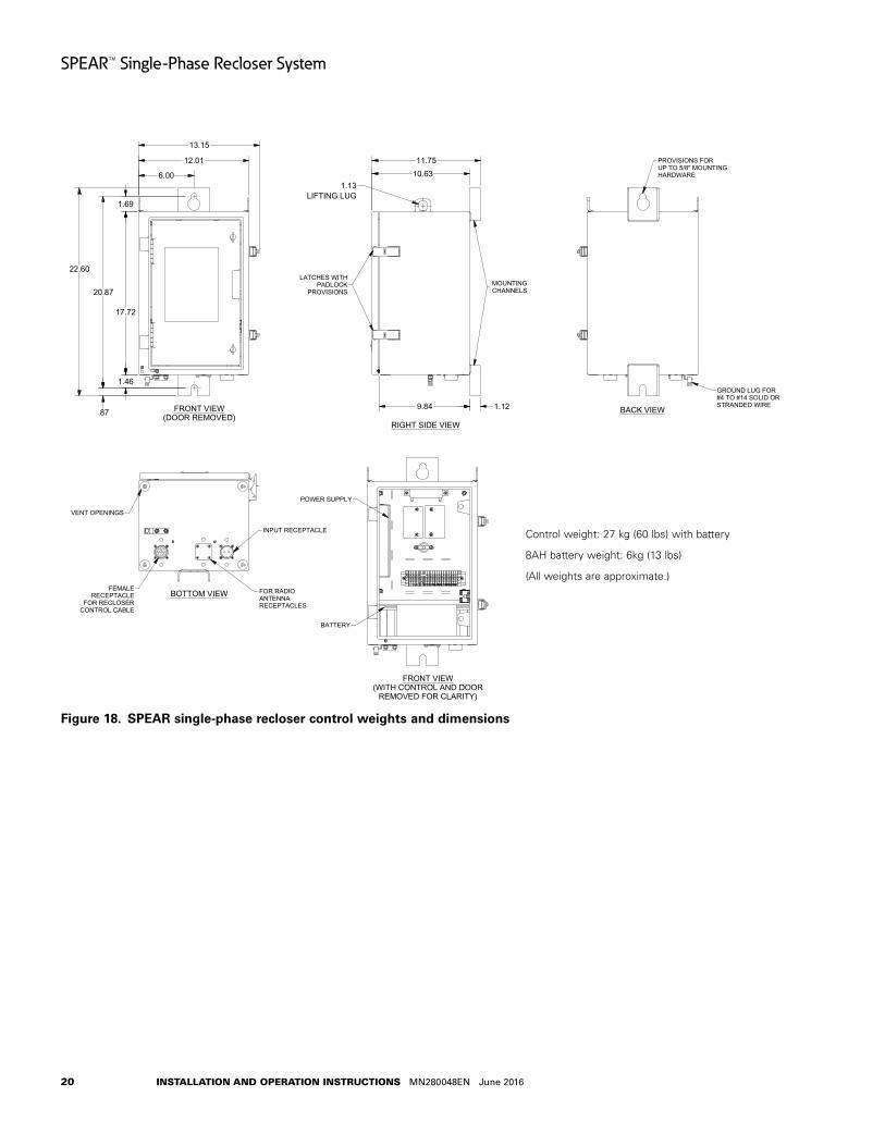
20
SPEAR™ Single-Phase Recloser System
INSTALLATION AND OPERATION INSTRUCTIONS MN280048EN June 2016
Figure 18 .
FRONT VIEW(DOOR REMOVED)
BOTTOM VIEW
FRONT VIEW(WITH CONTROL AND DOOR
REMOVED FOR CLARITY)
RIGHT SIDE VIEW
BACK VIEW
MODULE SIDE VIEW
FEMALERECEPTACLE
FOR RECLOSERCONTROL CABLE
INPUT RECEPTACLE
FOR RADIOANTENNARECEPTACLES
LATCHES WITHPADLOCK
PROVISIONS
1.13LIFTING LUG
10.63
MOUNTINGCHANNELS
1.129.84
PROVISIONS FORUP TO 5/8" MOUNTINGHARDWARE
GROUND LUG FOR#4 TO #14 SOLID ORSTRANDED WIRE
12.01
VENT OPENINGS
6.00
22.60
1.69
20.87
17.72
1.46
.87
POWER SUPPLY
BATTERY
OPTIONAL RS-232COMMUNICATIONPORT
CONTACT I/OMODULE
CONTROL MODULE
13.15
11.75
SHIELD WIRECONNECTION
Control weight: 27 kg (60 lbs) with battery
8AH battery weight: 6kg (13 lbs)
(All weights are approximate.)
SPEAR single-phase recloser control weights and dimensions
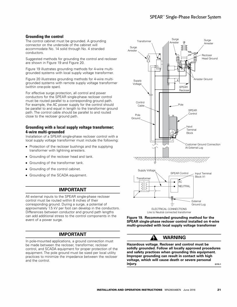
21
SPEAR™ Single-Phase Recloser System
INSTALLATION AND OPERATION INSTRUCTIONS MN280048EN June 2016
Grounding the controlThe control cabinet must be grounded. A grounding connector on the underside of the cabinet will accommodate No. 14 solid through No. 4 stranded conductors.
Suggested methods for grounding the control and recloser are shown in Figure 19 and Figure 20.
Figure 19 illustrates grounding methods for 4-wire multi-grounded systems with local supply voltage transformer.
Figure 20 illustrates grounding methods for 4-wire multi-grounded systems with remote supply voltage transformer (within one-pole span).
For effective surge protection, all control and power conductors for the SPEAR single-phase recloser control must be routed parallel to a corresponding ground path. For example, the AC power supply for the control should be parallel to and equal in length to the transformer ground path. The control cable should be parallel to and routed close to the recloser ground path.
Grounding with a local supply voltage transformer; 4-wire multi-groundedInstallation of a SPEAR single-phase recloser control with a local supply voltage transformer must include the following:
Protection of the recloser bushings and the supplying transformer with lightning arresters.
Grounding of the recloser head and tank.
Grounding of the transformer tank.
Grounding of the control cabinet.
Grounding of the SCADA equipment.
IMPORTANTAll external inputs to the SPEAR single-phase recloser control must be routed within 8 inches of their corresponding ground. During a surge, a potential of approximately 1.5 kV per foot can develop in the conductors. Differences between conductor and ground path lengths can add additional stress to the control components in the event of a power surge.
IMPORTANTIn pole-mounted applications, a ground connection must be made between the recloser, transformer, recloser control, and SCADA equipment for proper protection of the equipment. The pole ground must be sized per local utility practices to minimize the impedance between the recloser and the control.
Figure 19 .
SurgeArrester
RecloserHead Ground
SurgeArresterTransformer
SurgeArrester
Arrester Ground
SPEAR Recloser
Pole
SupplyVoltage
PoleGround
SPEARControl
Customer Ground ConnectionAt External Lug
NE
UA
C
GNDNEUAC
InputTerminalBlock
ControlCable
AC
NEUTRAL
SPEAR ControlSupply Voltage
Transformer
ELECTRICAL CONNECTIONS Line to Neutral connected transformer
Input TerminalBlock X1
External Ground Lug
SurgeArrester
RecloserHead Ground
SurgeArresterTransformer
SurgeArrester
Arrester Ground
SPEAR Recloser
Pole
SupplyVoltage
PoleGround
SPEARControl
Customer Ground ConnectionAt External Lug
NE
UA
C
GNDNEUAC
InputTerminalBlock
ControlCable
AC
NEUTRAL
SPEAR ControlSupply Voltage
Transformer
ELECTRICAL CONNECTIONS Line to Neutral connected transformer
Input TerminalBlock X1
External Ground Lug
Recommended grounding method for the SPEAR single-phase recloser control installed on 4-wire multi-grounded with local supply voltage transformer
WARNINGHazardous voltage . Recloser and control must be solidly grounded . Follow all locally approved procedures and safety practices when grounding this equipment . Improper grounding can result in contact with high voltage, which will cause death or severe personal injury . G115 .1
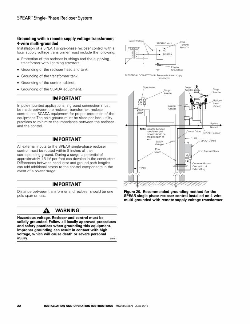
22
SPEAR™ Single-Phase Recloser System
INSTALLATION AND OPERATION INSTRUCTIONS MN280048EN June 2016
Grounding with a remote supply voltage transformer; 4-wire multi-groundedInstallation of a SPEAR single-phase recloser control with a local supply voltage transformer must include the following:
Protection of the recloser bushings and the supplying transformer with lightning arresters.
Grounding of the recloser head and tank.
Grounding of the transformer tank.
Grounding of the control cabinet.
Grounding of the SCADA equipment.
IMPORTANTIn pole-mounted applications, a ground connection must be made between the recloser, transformer, recloser control, and SCADA equipment for proper protection of the equipment. The pole ground must be sized per local utility practices to minimize the impedance between the recloser and the control.
IMPORTANTAll external inputs to the SPEAR single-phase recloser control must be routed within 8 inches of their corresponding ground. During a surge, a potential of approximately 1.5 kV per foot can develop in the conductors. Differences between conductor and ground path lengths can add additional stress to the control components in the event of a power surge.
IMPORTANTDistance between transformer and recloser should be one pole span or less.
WARNINGHazardous voltage . Recloser and control must be solidly grounded . Follow all locally approved procedures and safety practices when grounding this equipment . Improper grounding can result in contact with high voltage, which will cause death or severe personal injury . G115 .1
Figure 20 .
SurgeArrester
RecloserHeadGround
SupplyVoltage
PoleGround
SPEAR Recloser
Pole
SurgeArrester
Transformer
ArresterGround
SPEAR Control
HOTNEUGND
NE
UA
C
Input Terminal Block
Control Cable
SurgeArrester
Customer Ground Connection atExternal Lug
AC
NEUTRAL
SPEAR ControlSupply Voltage
Transformer
ELECTRICAL CONNECTIONS - Remote dedicated supply transformer
InputTerminalBlock X1
ExternalGround Lug
Note: Distance between transformer and recloser should be one pole span or less.
System
Neutral
Pole
SurgeArrester
RecloserHeadGround
SupplyVoltage
PoleGround
Pole
SPEAR Recloser
Pole
SurgeArrester
Transformer
ArresterGround
SPEAR Control
HOTNEUGND
NE
UA
C
Input Terminal Block
Control Cable
SurgeArrester
ArresterGround
Customer Ground Connectionat External Lug
AC
NEUTRAL
SPEAR ControlSupply Voltage
Transformer
ELECTRICAL CONNECTIONS - Remote dedicated supply transformer
InputTerminalBlock X1
ExternalGround Lug
Note: Distance between transformer and recloser should be one pole span or less.
System
Neutral
Recommended grounding method for the SPEAR single-phase recloser control installed on 4-wire multi-grounded with remote supply voltage transformer
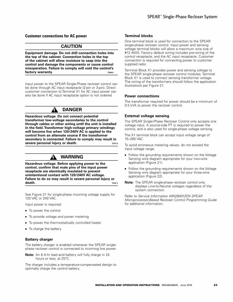
23
SPEAR™ Single-Phase Recloser System
INSTALLATION AND OPERATION INSTRUCTIONS MN280048EN June 2016
Customer connections for AC power
CAUTIONEquipment damage . Do not drill connection holes into the top of the cabinet . Connection holes in the top of the cabinet will allow moisture to seep into the control and damage the components or cause control misoperation . Failure to comply will void the control’s factory warranty . T249 .0
Input power to the SPEAR Single-Phase recloser control can be done through AC input receptacle (2-pin or 3-pin). Direct customer connection to Terminal X1 for AC input power can also be done if AC input receptacle option is not ordered.
DANGERHazardous voltage . Do not connect potential transformer low-voltage secondaries to the control through cables or other wiring until the unit is installed in the field . Transformer high-voltage primary windings will become live when 120/240V AC is applied to the control from an alternate source if the transformer secondary is connected . Failure to comply may result in severe personal injury or death . T371 .2
WARNINGHazardous voltage . Before applying power to the control, confirm that male pins of the input power receptacle are electrically insulated to prevent unintentional contact with 120/240V AC voltage . Failure to do so may result in severe personal injury or death . T372 .1
See Figure 21 for single-phase incoming voltage supply for 120 VAC or 240 VAC.
Input power is required:
To power the control
To provide voltage and power metering
To power the thermostatically controlled heater
To charge the battery
Battery chargerThe battery charger is enabled whenever the SPEAR single-phase recloser control is connected to incoming line power.
otee:N An 8 A-hr lead acid battery will fully charge in 24 hours or less, at 25°C.
The charger includes a temperature-compensated design to optimally charge the control battery.
Terminal blocksOne terminal block is used for connection to the SPEAR single-phase recloser control. Input power and sensing voltage terminal blocks will allow a maximum wire size of #12 AWG. Factory default wiring includes pre-wiring of the control receptacle, and the AC input receptacle. Customer connection is required for connecting power to customer supplied radio.
Terminal Block X1 provides power and sensing voltage to the SPEAR single-phase recloser control modules. Terminal Block X1 is used to connect sensing transformer voltage. The wiring of the transformers should follow the application illustrations per Figure 21.
Power connectionsThe transformer required for power should be a minimum of 0.5 kVA to power the recloser control.
External voltage sensingThe SPEAR Single-Phase Recloser Control only accepts one voltage input. A source-side PT is required to power the control, and is also used for single-phase voltage sensing.
The X1 terminal block can accept input voltage range of 15–265 VAC.
To avoid erroneous metering values, do not exceed the input voltage range.
Follow the grounding requirements shown on the Voltage Sensing wire diagram appropriate for your two-wire application (Figure 21).
Follow the grounding requirements shown on the Voltage Sensing wire diagram appropriate for your three-wire application (Figure 22).
otee:N The SPEAR single-phase recloser control only displays Line-to-Neutral voltages regardless of the system connection.
Refer to Service Information MN280012EN SPEAR Microprocessor-Based Recloser Control Programming Guide for additional information.

24
SPEAR™ Single-Phase Recloser System
INSTALLATION AND OPERATION INSTRUCTIONS MN280048EN June 2016
Figure 21 .
Hea
ter 2
Hea
ter 1
045
047
048
046
FU1
013
012
012
013
120/
240
VAC
CU
STO
MER
CO
NTR
OL
PO
WER
INP
UT
R2
BLK
WH
T*
BA
CU
STO
MER
WIR
ING
120/
240
VAC
CU
STO
MER
CO
NTR
OL
PO
WER
INP
UT
NEU
TRA
L*
HO
T
TO R
1-J
015
015
OP
TIO
NA
L FA
CTO
RY
AC
CES
SO
RY
WIR
ING
* N
eutr
al m
ust
be c
onne
cted
to
Ear
th g
roun
d, e
xter
nal t
o t
he c
ontr
ol, i
n or
der
to e
nsur
e ac
cura
te v
olta
ge r
eadi
ng
120 or 240 VAC 2-wire control power input (shown with default factory wiring connected to single-phase voltage input supply)

25
SPEAR™ Single-Phase Recloser System
INSTALLATION AND OPERATION INSTRUCTIONS MN280048EN June 2016
Figure 22 .
Hea
ter 2
Hea
ter 1
045
047
048
046
FU1
013
012
012
013
BLK
WH
T*
BA
CU
STO
MER
WIR
ING
120/
240
VAC
CU
STO
MER
CO
NTR
OL
PO
WER
INP
UT
NEU
TRA
L*
HO
T
TO R
1-J
015
015
C
BR
AID
120/
240
VAC
CU
STO
MER
CO
NTR
OL
PO
WER
INP
UT
R2
OP
TIO
NA
L FA
CTO
RY
AC
CES
SO
RY
WIR
ING
* N
eutr
al m
ust
be c
onne
cted
to
Ear
th g
roun
d, e
xter
nal t
o t
he c
ontr
ol, i
n or
der
to e
nsur
e ac
cura
te v
olta
ge r
eadi
ng
120 or 240 VAC 3-wire control power input (shown with default factory wiring connected to single-phase voltage input supply)

26
SPEAR™ Single-Phase Recloser System
INSTALLATION AND OPERATION INSTRUCTIONS MN280048EN June 2016
Customer connections for contact I/O module option
CAUTIONEquipment damage . Do not drill connection holes into the top of the cabinet . Connection holes in the top of the cabinet will allow moisture to seep into the control and damage the components or cause control misoperation . Failure to comply will void the control’s factory warranty . T249 .0
The Contact I/O module (Figure 23) permits connection of contact-type input devices (switches, relays) and indicating devices (relays, LEDs, lamps) to the SPEAR single-phase recloser control to affect local Contact input/output (I/O). The Contact I/O module accessory is used for supplementing normal local controls and status indicators for Contact I/O functions.
IMPORTANTThe control gives priority to TCC timing and issuing a trip signal rather than changing the status of a Contact I/O module output or responding to a Contact I/O module input. Refer to Table 9 for I/O response times.
Figure 23 .
FRONT VIEW(DOOR REMOVED)
BOTTOM VIEW
FRONT VIEW(WITH CONTROL AND DOOR
REMOVED FOR CLARITY)
RIGHT SIDE VIEW
BACK VIEW
MODULE SIDE VIEW
FEMALERECEPTACLE
FOR RECLOSERCONTROL CABLE
INPUT RECEPTACLE
FOR RADIOANTENNARECEPTACLES
LATCHES WITHPADLOCK
PROVISIONS
1.13LIFTING LUG
10.63
MOUNTINGCHANNELS
1.129.84
PROVISIONS FORUP TO 5/8" MOUNTINGHARDWARE
GROUND LUG FOR#4 TO #14 SOLID ORSTRANDED WIRE
12.01
VENT OPENINGS
6.00
22.60
1.69
20.87
17.72
1.46
.87
POWER SUPPLY
BATTERY
OPTIONAL RS-232COMMUNICATIONPORT
CONTACT I/OMODULE
CONTROL MODULE
13.15
11.75
SHIELD WIRECONNECTION
Contact I/O module
The Contact I/O module comes standard with each SPEAR single-phase recloser control. This contains two factory set inputs and two outputs for Contact I/O functionality. These inputs and output contacts are not user programmable.
The SPEAR control does not support additional Contact I/O modules.
Whetting voltage is supplied from VTC OUT (side of SPEAR single-phase recloser control module) for the Contact I/O inputs terminal block on the back panel as shown in Figure 24.
The two Contact I/O outputs are Form C relay contacts,and are of non-latching type. Refer to Table 10 for output fusing recommendations.
otee:N Latching is defined as an output that retains its status when control power is removed.
Non-latching is defined as an output that returns to a default status when control power is removed.
otee:N Following a firmware upgrade the Contact I/O module output relays will revert to the de-energized state.
Table 9 . Contact I/O option module input ratingsSpecification Value
Minimum detection level10 V (AC rms or DC) (50 or 60 Hz) Using control-supplied whetting voltage is recommended.
Maximum applied voltage 250 VAC, rms, or 125 VDCNominal input loading 2 mA per input (internally current limited)
Typical control response time 50 msec (Note: Protection tasks take priority over input activity.)
Minimum input pulse time 250 msecMinimum transition time between pulse inputs 250 msec
Input protectionShunting type using MOVs and capacitors. Optical isolation from input to system. (1500 VAC, rms)
Hi-pot capability
3.150 kV DC for 1 second, from one input set to the next or from one pin to chassis, but not across the two terminals of a single input (due to internal MOVs).
Table 10 . Output ratingsSpecification ValueMaximum switching voltage 250 VAC, rms or 125 VDCMaximum switching loading Refer to Figure 25.Maximum pickup time 8 msec (not including control response time)Maximum release time 15 msec (not including control response time)
Output protectionShunting type using MOVs and capacitors. 1500 VAC, rms isolation between coil and contacts
Hi-pot capability
3.150 kV DC for 1 second, from one output to the next or from one pin to chassis, but not across the two terminals of a single output (due to output protection).
Fusing Outputs are not internally fuse-protected. Customer-supplied fusing is recommended.
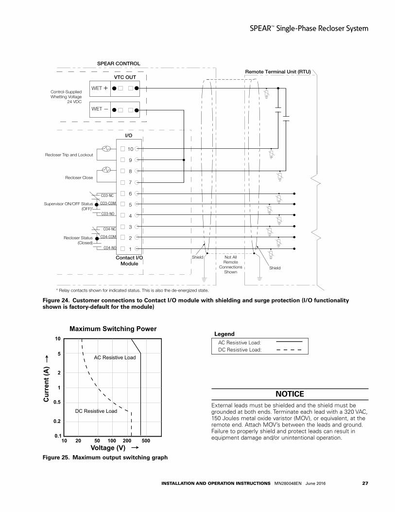
27
SPEAR™ Single-Phase Recloser System
INSTALLATION AND OPERATION INSTRUCTIONS MN280048EN June 2016
Figure 24 .
SPEAR CONTROL
Remote Terminal Unit (RTU)
Not AllRemote
ConnectionsShown
Contact I/OModule
I/O
Recloser Trip and Lockout
Recloser Close
Supervisor ON/OFF Status(OFF)*
Recloser Status(Closed)
6
5
4
3
2
1
VTC OUT
WET +
WET —
Control-SuppliedWhetting Voltage
24 VDC
Shield
Shield
CO4-NO
CO3-NO
CO3-NC
CO3-COM
CO4-NC
CO4-COM
* Relay contacts shown for indicated status. This is also the de-energized state.
10
9
8
7
Customer connections to Contact I/O module with shielding and surge protection (I/O functionality shown is factory-default for the module)
Figure 25 .
10
5
2
1
0.5
0.2
0.110 20 50 100 200 500
Cur
rent
(A)
Voltage (V)
Maximum Switching Power
AC Resistive Load
DC Resistive Load
Maximum output switching graph
AC Resistive Load: DC Resistive Load:
Legend
NOTICEExternal leads must be shielded and the shield must be grounded at both ends. Terminate each lead with a 320 VAC, 150 Joules metal oxide varistor (MOV), or equivalent, at the remote end. Attach MOV’s between the leads and ground. Failure to properly shield and protect leads can result in equipment damage and/or unintentional operation.

28
SPEAR™ Single-Phase Recloser System
INSTALLATION AND OPERATION INSTRUCTIONS MN280048EN June 2016
Before placing the control and recloser into service
CAUTION Equipment misoperation . Do not connect this control to an energized recloser until all control settings have been properly programmed and verified . Refer to the programming information for this control . Failure to comply can result in control and recloser misoperation, equipment damage, and personal injury . G110 .3
IMPORTANTTo avoid damage to the wiring or batteries, do not transport the control with the batteries installed.
Prior to placing the control and recloser into service, the following installation procedures must be properly completed and verified:
1. Control properly mounted for the installation.
2. Recloser installed according to all locally approved standards and practices.
3. AC disconnect switches installed.
4. Control and recloser properly grounded in accordance with guidelines in this manual and the applicable recloser manual.
5. Control cable properly connected and supported.
6. Control battery connected and tested for proper operation.
otee:N The battery test runs within 60 seconds upon power-up of the control.
otee:N The battery cannot be tested when the control is powered from the battery only (no AC power). If a battery test is attempted with battery power only, the test results will display as ATTENTION – 4 (Battery Test Blocked).
View battery information and test battery operation as follows:
A. Scroll down the front panel HMI to the BATTERY menu item and press the ENTER button. Battery Voltage and Current will be displayed:
VBat = XX.XX Volts
IBat = -X.XX Amps
B. Press the down arrow button to scroll to the Test Battery command. Press the ENTER button.
The following message will appear: Test Battery (CONFIRM).
C. Press the ENTER key. The (TESTING...) message will appear. (The test duration is approximately five seconds.)
If the battery is OK, the (PASS) message will appear.
If the battery is not OK, one of these messages will appear:
“ATTENTION – 1” indicates Battery Test Trouble*
“ATTENTION – 2” indicates Battery Test Failed
“ATTENTION – 3” indicates Battery Test Currently Running
“ATTENTION – 4” indicates Battery Test Blocked**
* Battery Test Trouble indicates that the test results were not lower than battery failure voltage (15 V) and not higher than the test voltage (22.8 V).
** Battery Test Blocked indicates a battery test was attempted with battery power only. The battery cannot be tested when the control is powered from the battery only (no AC power).
D. The battery test results can be viewed by pressing the down arrow. The following information will be displayed:
VBat = XX.XX Volts
IBat = -X.XX Amps
7. AC power connected to the control.
otee:N The control includes a Power Save feature that will turn off the LEDs and backlit LCD display after 15 minutes of inactivity at the front panel (no buttons pressed). The CONTROL OK and HOT LINE TAG LEDs are not affected by the power save mode. Pressing any key on the front panel will turn the LCD backlight on and restore all LEDs to their current on/off states.
8. All control programming entered and verified by appropriate personnel.
otee:N Refer to Service Information MN280012EN SPEAR Single-Phase Recloser Control Programming Guide for additional information.
9. Control clock set to the correct time.
otee:N Refer to the Clock Menu section of Service Information MN280012EN SPEAR Single-Phase Recloser Control Programming Guide for additional information.
10. Customer connections for remote and supervisory operation checked and completed in accordance with proper shielding and surge protection (Figure 24).
NOTICEExternal leads must be shielded and the shield must be grounded at both ends. Terminate each lead with a 320 VAC, 150 Joules metal oxide varistor (MOV), or equivalent, at the remote end. Attach MOV’s between the leads and ground. Failure to properly shield and protect leads can result in equipment damage and/or unintentional operation.

29
SPEAR™ Single-Phase Recloser System
INSTALLATION AND OPERATION INSTRUCTIONS MN280048EN June 2016
Control accessories
These accessories are available. Contact your Eaton representative for additional information.
Cabinet ordering accessoriesANSI 304 stainless steel cabinet construction available as an ordering option. Refer to SPEAR Catalog CA280001EN for ordering information.
Incoming power receptaclesThe Incoming Power Receptacle allows the user to conveniently plug the power cable into the control, eliminating the need for hardwiring to the control. Table 11 includes the available input receptacle and cable for the SPEAR single-phase recloser control.
Cable locking sleevesTo prevent detachment of the control cable from the control cabinet by unauthorized personnel, a cable-locking sleeve (Catalog Number KSPRC-1772-X [replace X with quantity: maximum 3]) is available to enclose the cable plug. The plug is passed through the sleeve and the sleeve is then fastened from inside the control cabinet. There is no access to the cable receptacle without opening the locked cabinet door and detaching the sleeve.
Table 11 . Receptacles and wiring; input cablesDescription Catalog number120 VAC or 240 VAC input receptacle, 2-pin KSPRC-1775-H120 VAC or 240 VAC input receptacle, 3-pin KSPRC-1775-JNo input receptacle, for hard-wiring input KSPRC-1775-0AC Input Cable, 120 or 240 VAC, 2-wire for 2-pin input for use with KSPRC-1775-H receptacle. Replace X with desired length. Select from 0 to 50 feet.
KA11ME1-X
Armored (10 ft.) input cable. Replace X with desired length. Select from 10 to 50 feet. KA124ME-X
AC Input Cable, 120 VAC, 3-wire for 3-pin input for use with KSPRC-1775-J receptacle. Replace X with desired length. Select from 0 to 50 feet.
KME4-67-3-X
Note: To order a mating plug body only (for use with customer supplied cable), replace “X” with length of “0”.
Automation accessory packagesThe SPEAR single-phase recloser control includes an auxiliary power supply that provides a customer connection to 13.5 VDC. This source is intended to be used to power radios and other communications support equipment for connection to SCADA and other remote communications systems. The power supply is backed up by the control batteries in the SPEAR single-phase recloser control cabinet, and will continue to provide power to connected accessories under loss of AC line power to the recloser control. A maximum of 12 W continuous and 30 W peak (intermittent) power can be delivered to accessories connected to the auxiliary power supply.
A variety of automation packages are available to be used in conjunction with the auxiliary power supply to facilitate the mounting and proper connection of antennas to radios mounted in the control cabinet. Packages are available to support many popular radio technologies and frequency bands. See Table 12 for details on each of the available automation accessory packages.
otee:N A maximum of one automation accessory can be ordered. KSPRC-1774-29 is not included in this maximum.
Table 12 . Automation accessory packages†
Description Catalog numberWireless communication provisions package 13.5 VDC interface board, radio mounting tray (Radio and communications interface cards not included)
KSPRC-1774-29
Cellular communications connection and protection package 32” SMA(m)-N(m) coax pigtail, 700MHz – 2GHz PolyPhaser and mounting hardware, N(f)-type external termination
KSPRC-1774-22*
WiFi/WiMax communications connection and protection package 32” SMA(m)-N(m) coax pigtail, 2GHz – 6GHz Polyphaser and mounting hardware, N(f)-type external termination, TNC(m)-SMA(m) inline coaxial adapter
KSPRC-1774-23*
125MHz to 1GHz N-terminated radio connection and protection package 25” N(m)-N(m) coax pigtail, 125MHz to 1GHz PolyPhaser and mounting hardware, N(f)-type external termination
KSPRC-1774-24*
700MHz to 2GHz TNC-terminated radio connection and protection package 32” TNC(m)-N(m) coax pigtail, 700MHz to 2GHz PolyPhaser and mounting hardware, N(f)-type external termination
KSPRC-1774-25*
PolyPhaser and mounting hardware: 125MHz – 1GHz KSPRC-1774-A*PolyPhaser and mounting hardware: 700MHz – 2GHz KSPRC-1774-B*PolyPhaser and mounting hardware: 2GHz – 6GHz KSPRC-1774-C*† Requires Communication Interface Option: (1) RS-232 Interface * Requires that the KSPRC-1774-29 Wireless Communication Provisions Package also be orderedNote: The SPEAR control includes a 3-ft RS-232 cable with 90 degree connector when RS-232 Communication Interface option is ordered.
Table 13 . Miscellaneous accessoriesDescription Catalog number120 VAC Battery Charger for spare batteries KME5-60-1
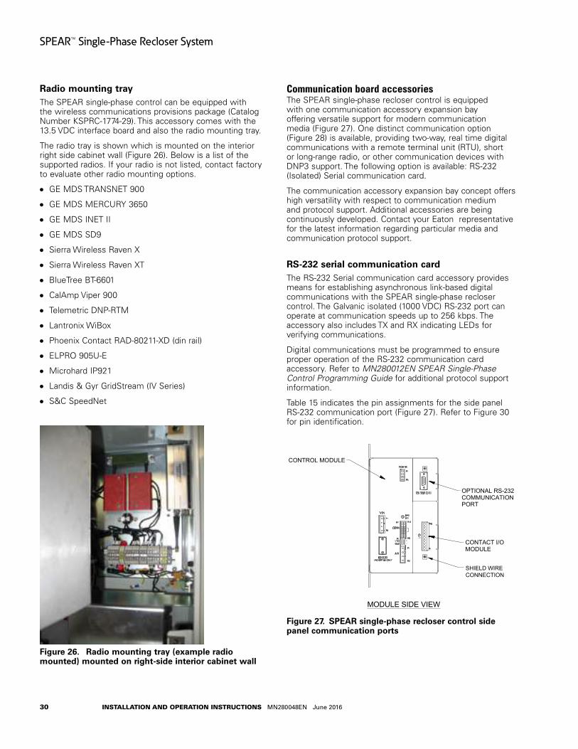
30
SPEAR™ Single-Phase Recloser System
INSTALLATION AND OPERATION INSTRUCTIONS MN280048EN June 2016
Radio mounting trayThe SPEAR single-phase control can be equipped with the wireless communications provisions package (Catalog Number KSPRC-1774-29). This accessory comes with the 13.5 VDC interface board and also the radio mounting tray.
The radio tray is shown which is mounted on the interior right side cabinet wall (Figure 26). Below is a list of the supported radios. If your radio is not listed, contact factory to evaluate other radio mounting options.
GE MDS TRANSNET 900
GE MDS MERCURY 3650
GE MDS INET II
GE MDS SD9
Sierra Wireless Raven X
Sierra Wireless Raven XT
BlueTree BT-6601
CalAmp Viper 900
Telemetric DNP-RTM
Lantronix WiBox
Phoenix Contact RAD-80211-XD (din rail)
ELPRO 905U-E
Microhard IP921
Landis & Gyr GridStream (IV Series)
S&C SpeedNet
Figure 26 . Radio mounting tray (example radio mounted) mounted on right-side interior cabinet wall
Communication board accessoriesThe SPEAR single-phase recloser control is equipped with one communication accessory expansion bay offering versatile support for modern communication media (Figure 27). One distinct communication option (Figure 28) is available, providing two-way, real time digital communications with a remote terminal unit (RTU), short or long-range radio, or other communication devices with DNP3 support. The following option is available: RS-232 (Isolated) Serial communication card.
The communication accessory expansion bay concept offers high versatility with respect to communication medium and protocol support. Additional accessories are being continuously developed. Contact your Eaton representative for the latest information regarding particular media and communication protocol support.
RS-232 serial communication cardThe RS-232 Serial communication card accessory provides means for establishing asynchronous link-based digital communications with the SPEAR single-phase recloser control. The Galvanic isolated (1000 VDC) RS-232 port can operate at communication speeds up to 256 kbps. The accessory also includes TX and RX indicating LEDs for verifying communications.
Digital communications must be programmed to ensure proper operation of the RS-232 communication card accessory. Refer to MN280012EN SPEAR Single-Phase Control Programming Guide for additional protocol support information.
Table 15 indicates the pin assignments for the side panel RS-232 communication port (Figure 27). Refer to Figure 30 for pin identification.
Figure 27 .
FRONT VIEW(DOOR REMOVED)
BOTTOM VIEW
FRONT VIEW(WITH CONTROL AND DOOR
REMOVED FOR CLARITY)
RIGHT SIDE VIEW
BACK VIEW
MODULE SIDE VIEW
FEMALERECEPTACLE
FOR RECLOSERCONTROL CABLE
INPUT RECEPTACLE
FOR RADIOANTENNARECEPTACLES
LATCHES WITHPADLOCK
PROVISIONS
1.13LIFTING LUG
10.63
MOUNTINGCHANNELS
1.129.84
PROVISIONS FORUP TO 5/8" MOUNTINGHARDWARE
GROUND LUG FOR#4 TO #14 SOLID ORSTRANDED WIRE
12.01
VENT OPENINGS
6.00
22.60
1.69
20.87
17.72
1.46
.87
POWER SUPPLY
BATTERY
OPTIONAL RS-232COMMUNICATIONPORT
CONTACT I/OMODULE
CONTROL MODULE
13.15
11.75
SHIELD WIRECONNECTION
SPEAR single-phase recloser control side panel communication ports

31
SPEAR™ Single-Phase Recloser System
INSTALLATION AND OPERATION INSTRUCTIONS MN280048EN June 2016
Figure 28 . Side-panel serial RS-232 communication port option
Table 14 . Communication support equipmentDescription Catalog numberUSB cable, Type A male-to-Type B male connectors, 2 meters (6.5 ft.) length KSPRC-66
Figure 29 . USB cable
Figure 30 .
RS-232 DTE
J2 DB-9 Connector
1 2 3 4 5
6 7 8 9
RS-232 serial communication port pin identification
Table 15 . Serial communication port pin assignmentsPin number Signal name1 DCD Carrier Detect2 RXD Receive Data3 TXD Transmit Data4 DTR Data Terminal Ready5 GND Signal Ground6 DSR Data Set Ready (Not Connected)7 RTS Request to Send8 CTS Clear to Send9 NC Not Used10 (Shroud) Chassis Ground
Recloser accessories
Terminal optionsSPEAR single-phase reclosers can be specified with eyebolt terminals (400 A , 630 A, and 800 A), two-hole (400 A, 630 A) or four-hole (800 A) flat-pad terminals, or stud-type terminals (400 A, 630 A, and 800 A).
The eyebolt, flat-pad, and stud terminals are made of copper alloys. Eaton recommends terminal connection to copper wires to optimize the electrical connection. Aluminum cables may produce aluminum oxide sufficient to compromise the electrical connections.
Anti-oxide coatings for temporary protection of wire-brushed, aluminum cable connections to flat-pad or stud terminals must be maintained at intervals determined by the customer based on load current, climate, and other installation conditions.
Copper conductors only are recommended for eyebolt terminals.
Mounting hangers
Crossarm mounting hangerA crossarm mounting hanger is available for crossarm installation. These are available in sets of two; one set is needed for each SPEAR single-phase recloser. To order this accessory, specify part number KA39H2.
Pole-mounting accessoryThe 15 kV and 27 kV SPEAR single-phase reclosers can be directly mounted to the pole using the built-in tank mounting channels for BIL rating of 125 kV and lower. Due to electrical clearances, the pole-mounting hanger accessory is recommended for mounting either the 27kV (with 150 kV BIL accessory), or 38 kV (170 kV BIL) SPEAR single-phase recloser to the pole. To order this accessory, specify part number KSPR-364.
Figure 31 .
6.6 in
18.0 in
0.81 in
(168 mm)
(457 mm)
Pole-mounting hanger views
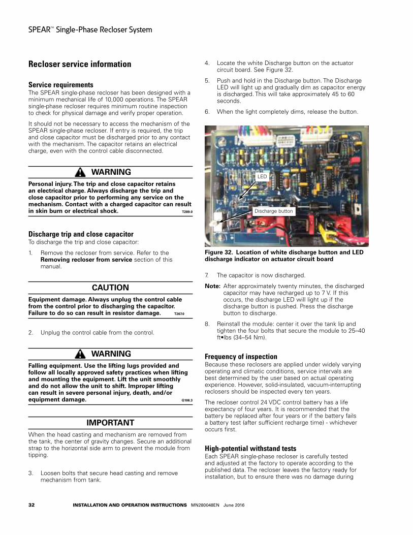
32
SPEAR™ Single-Phase Recloser System
INSTALLATION AND OPERATION INSTRUCTIONS MN280048EN June 2016
Recloser service information
Service requirementsThe SPEAR single-phase recloser has been designed with a minimum mechanical life of 10,000 operations. The SPEAR single-phase recloser requires minimum routine inspection to check for physical damage and verify proper operation.
It should not be necessary to access the mechanism of the SPEAR single-phase recloser. If entry is required, the trip and close capacitor must be discharged prior to any contact with the mechanism. The capacitor retains an electrical charge, even with the control cable disconnected.
WARNINGPersonal injury . The trip and close capacitor retains an electrical charge . Always discharge the trip and close capacitor prior to performing any service on the mechanism . Contact with a charged capacitor can result in skin burn or electrical shock . T289 .0
Discharge trip and close capacitorTo discharge the trip and close capacitor:
1. Remove the recloser from service. Refer to the Removing recloser from service section of this manual.
CAUTIONEquipment damage . Always unplug the control cable from the control prior to discharging the capacitor . Failure to do so can result in resistor damage . T267 .0
2. Unplug the control cable from the control.
WARNINGFalling equipment . Use the lifting lugs provided and follow all locally approved safety practices when lifting and mounting the equipment . Lift the unit smoothly and do not allow the unit to shift . Improper lifting can result in severe personal injury, death, and/or equipment damage . G106 .3
IMPORTANTWhen the head casting and mechanism are removed from the tank, the center of gravity changes. Secure an additional strap to the horizontal side arm to prevent the module from tipping.
3. Loosen bolts that secure head casting and remove mechanism from tank.
4. Locate the white Discharge button on the actuator circuit board. See Figure 32.
5. Push and hold in the Discharge button. The Discharge LED will light up and gradually dim as capacitor energy is discharged. This will take approximately 45 to 60 seconds.
6. When the light completely dims, release the button.
Figure 32 .
LED
Discharge button
Location of white discharge button and LED discharge indicator on actuator circuit board
7. The capacitor is now discharged.
otee:N After approximately twenty minutes, the discharged capacitor may have recharged up to 7 V. If this occurs, the discharge LED will light up if the discharge button is pushed. Press the discharge button to discharge.
8. Reinstall the module: center it over the tank lip and tighten the four bolts that secure the module to 25–40 ft•lbs (34 –54 Nm).
Frequency of inspectionBecause these reclosers are applied under widely varying operating and climatic conditions, service intervals are best determined by the user based on actual operating experience. However, solid-insulated, vacuum-interrupting reclosers should be inspected every ten years.
The recloser control 24 VDC control battery has a life expectancy of four years. It is recommended that the battery be replaced after four years or if the battery fails a battery test (after sufficient recharge time) - whichever occurs first.
High-potential withstand testsEach SPEAR single-phase recloser is carefully tested and adjusted at the factory to operate according to the published data. The recloser leaves the factory ready for installation, but to ensure there was no damage during
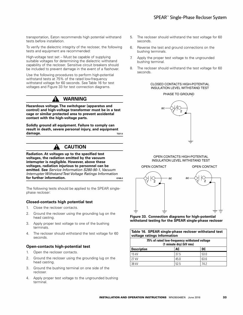
33
SPEAR™ Single-Phase Recloser System
INSTALLATION AND OPERATION INSTRUCTIONS MN280048EN June 2016
transportation, Eaton recommends high potential withstand tests before installation.
To verify the dielectric integrity of the recloser, the following tests and equipment are recommended:
High-voltage test set – Must be capable of supplying suitable voltages for determining the dielectric withstand capability of the recloser. Sensitive circuit breakers should be included to prevent damage in the event of a flashover.
Use the following procedures to perform high-potential withstand tests at 75% of the rated low-frequency withstand voltage for 60 seconds. See Table 16 for test voltages and Figure 33 for test connection diagrams.
WARNINGHazardous voltage . The switchgear (apparatus and control) and high-voltage transformer must be in a test cage or similar protected area to prevent accidental contact with the high-voltage parts .
Solidly ground all equipment . Failure to comply can result in death, severe personal injury, and equipment damage . T221 .5
CAUTIONRadiation . At voltages up to the specified test voltages, the radiation emitted by the vacuum interrupter is negligible . However, above these voltages, radiation injurious to personnel can be emitted . See Service Information S280-90-1, Vacuum Interrupter Withstand Test Voltage Ratings Information for further information . G109 .2
The following tests should be applied to the SPEAR single-phase recloser:
Closed-contacts high potential test1. Close the recloser contacts.
2. Ground the recloser using the grounding lug on the head casting.
3. Apply proper test voltage to one of the bushing terminals.
4. The recloser should withstand the test voltage for 60 seconds.
Open-contacts high-potential test1. Open the recloser contacts.
2. Ground the recloser using the grounding lug on the head casting.
3. Ground the bushing terminal on one side of the recloser.
4. Apply proper test voltage to the ungrounded bushing terminal.
5. The recloser should withstand the test voltage for 60 seconds.
6. Reverse the test and ground connections on the bushing terminals.
7. Apply the proper test voltage to the ungrounded bushing terminal.
8. The recloser should withstand the test voltage for 60 seconds.
Figure 33 .
1 2
CLOSED CONTACTS HIGH-POTENTIALINSULATION LEVEL WITHSTAND TEST
1 2
OPEN CONTACT
1 2
OPEN CONTACT
OPEN CONTACTS HIGH-POTENTIALINSULATION LEVEL WITHSTAND TEST
ac ac
PHASE TO GROUND
ac
Connection diagrams for high-potential withstand testing for the SPEAR single-phase recloser
Table 16 . SPEAR single-phase recloser withstand test voltage ratings information
75% of rated low-frequency withstand voltage (1 minute dry) (kV rms)
Description AC DC15 kV 37.5 53.027 kV 45.0 63.638 kV 52.5 74.2
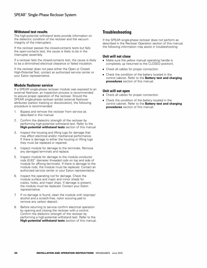
34
SPEAR™ Single-Phase Recloser System
INSTALLATION AND OPERATION INSTRUCTIONS MN280048EN June 2016
Withstand test resultsThe high-potential withstand tests provide information on the dielectric condition of the recloser and the vacuum integrity of the interrupters.
If the recloser passes the closed-contacts tests but fails the open-contacts test, the cause is likely to be in the interrupter assembly.
If a recloser fails the closed-contacts test, the cause is likely to be a diminished electrical clearance or failed insulation.
If the recloser does not pass either the Open or Closed High-Potential Test, contact an authorized service center or your Eaton representative.
Module flashover serviceIf a SPEAR single-phase recloser module was exposed to an external flashover, an inspection process is recommended to assure proper operation of the recloser. Should the SPEAR single-phase recloser exhibit external flashover attributes (carbon tracking or discoloration), the following procedure is recommended:
1. Bypass and remove the recloser from service as described in this manual.
2. Confirm the dielectric strength of the recloser by performing high-potential withstand test. Refer to the High-potential withstand tests section of this manual.
3. Inspect the housing and lifting lugs for damage that may affect electrical and/or mechanical performance. If there is damage to either the housing or lifting lugs they must be replaced or repaired.
4. Inspect module for damage to the terminals. Remove any damaged terminals and replace.
5. Inspect module for damage to the module conductor rods (0.63” diameter threaded rods on top and side of module for affixing terminals). If there is damage to the module rods, the module must be replaced. Contact an authorized service center or your Eaton representative.
6. Inspect the operating rod for damage. Check the module surface and major and minor sheds for cracks, holes, and major chips. If damage is present, the module must be replaced. Contact your Eaton representative.
7. If no damage is found, clean the module with isopropyl alcohol and a scratch-free, nylon scouring pad to remove any carbon deposit.
8. Before returning to service confirm electrical operation by opening and closing the recloser with a control. Confirm the dielectric strength of the recloser by performing a high-potential withstand test. Refer to the High-potential withstand tests section of this manual.
Troubleshooting
If the SPEAR single-phase recloser does not perform as described in the Recloser Operation section of this manual, the following information may assist in troubleshooting:
Unit will not close Make sure the yellow manual operating handle is
completely up (returned to the CLOSED position).
Check all cables for proper connection.
Check the condition of the battery located in the control cabinet. Refer to the Battery test and charging procedures section of this manual.
Unit will not open Check all cables for proper connection.
Check the condition of the battery located in the control cabinet. Refer to the Battery test and charging procedures section of this manual.
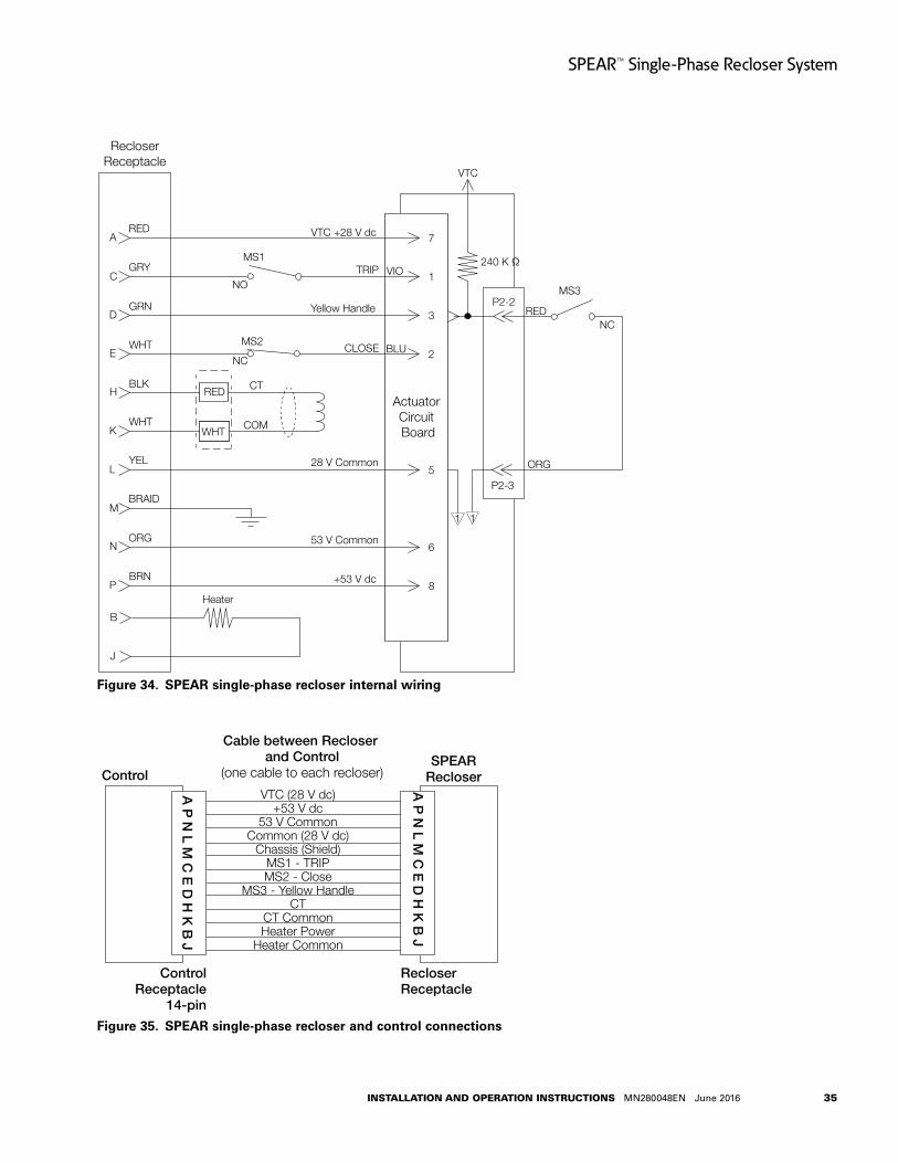
35
SPEAR™ Single-Phase Recloser System
INSTALLATION AND OPERATION INSTRUCTIONS MN280048EN June 2016
Figure 34 .
VIO
BLU
ARED
CGRY
GRN
BLK
WHT
WHT
YEL
BRAID
ORG
BRN
D
E
H
K
L
M
N
P
RED
WHT
CT
COM
VTC +28 V dc
NO
MS1TRIP
Yellow Handle
CLOSE
28 V Common
53 V Common
+53 V dc
RecloserReceptacle
ORG
RED
B
J
Heater
7
1
3
2
VTC
240 K Ω
P2-2MS3
NC
Actuator Circuit Board
P2-35
6
8
1 1
MS2
NC
SPEAR single-phase recloser internal wiring
Figure 35 .
VTC (28 V dc)+53 V dc
53 V CommonCommon (28 V dc)
Chassis (Shield)MS1 - TRIPMS2 - Close
MS3 - Yellow HandleCT
CT CommonHeater Power
Heater Common
A P
N L M
C E
D H
K B
J
SPEARRecloserControl
Cable between Recloser and Control
(one cable to each recloser)
ControlReceptacle
14-pin
RecloserReceptacle
A P
N L M
C E
D H
K B
J
SPEAR single-phase recloser and control connections

36
SPEAR™ Single-Phase Recloser System
INSTALLATION AND OPERATION INSTRUCTIONS MN280048EN June 2016
Control testing
CAUTIONEquipment misoperation . Do not connect this control to an energized recloser until all control settings have been properly programmed and verified . Refer to the programming information for this control . Failure to comply can result in control and recloser misoperation, equipment damage, and personal injury . G110 .3
IMPORTANTThe SPEAR single-phase recloser control can be taken out of service for testing and placed back into service without de-energizing its recloser and interrupting the system. However, during the time the control is out of service, the recloser is inoperative.
Testing an installed controlThe following tests to determine initial operation of the SPEAR single-phase recloser control can be performed while connected to an operating recloser.
otee:N These are the only tests performed on an installed, operating control.
1. Verify operating status of all indicator lights by pressing any key to reactivate the display and active LEDs.
2. Check the operational values for current, voltage, and other metering information.
otee:N Scroll through the LCD display messages by pressing the and cursor movement arrows underneath the LCD display on the programming panel (Figure 36).
Figure 36 .
DATA PORT
ENTER
EDITESC
BATTERYTEST
SUPER-VISORY
OFFNON
RECLOSE
HOT LINETAGTRIP
OFF
(LOCKOUT)
CLOSE
SPEAR Single-Phase Recloser Control
ON
ALTPROFILE
PHASE FAULT
ABOVE MIN TRIPALARM
CONTROL OK
AC POWER
BATTERY
LOCKOUT
OPEN
CLOSED
→*SETTINGS *SEQUENCE OF EVENTS *METERING
LCD display and cursor movement arrows
3. View battery information and test battery operation as follows:
A. Scroll down the front panel HMI to the BATTERY menu item and press the ENTER button. Code 081 Battery Voltage and Current will be displayed:
VBat = XX.XX Volts
IBat = -X.XX Amps
B. Press the down arrow button to scroll to the Test Battery command. Press the ENTER button.
The following message will appear: 082 Test Battery (CONFIRM).
C. Press the ENTER key. The (TESTING...) message will appear. (The test duration is approximately five seconds.)
If the battery is OK, the (PASS) message will appear.
If the battery is not OK, one of these messages will appear:
“ATTENTION – 1” indicates Battery Test Trouble*
“ATTENTION – 2” indicates Battery Test Failed
“ATTENTION – 3” indicates Battery Test Currently Running
“ATTENTION – 4” indicates Battery Test Blocked**
* Battery Test Trouble indicates that the test results were not lower than battery failure voltage (15V) and not higher than the test voltage (22.8V).
** Battery Test Blocked indicates a battery test was attempted with battery power only. The battery cannot be tested when the control is powered from the battery only (no AC power).
D. The battery test results can be viewed by pressing the down arrow. The following information will be displayed:
VBat = XX.XX Volts
IBat = -X.XX Amps
4. Verify the Control OK LED is illuminated on the control operator panel. The AC POWER LED indicates the presence of AC power (Figure 37).
otee:N The control includes a Power Save feature that will turn off the LEDs and backlit LCD display after 15 minutes of inactivity at the front panel (no buttons pressed). The CONTROL OK and HOT LINE TAG LEDs are not affected by the power save mode. Pressing any key on the front panel will turn the LCD backlight on and restore all LEDs to their current on/off states.
All other tests described in this Control testing section require the SPEAR single-phase recloser control to be removed from service, connected to a bypassed recloser, or tested at a location where the proper testing equipment is available.
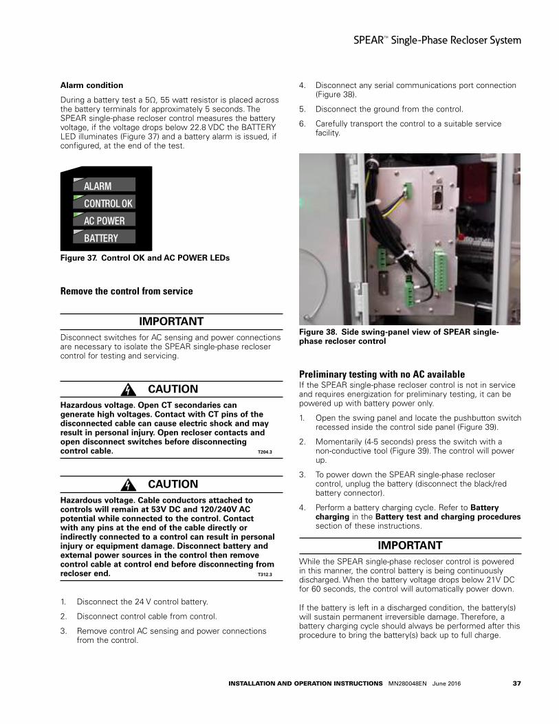
37
SPEAR™ Single-Phase Recloser System
INSTALLATION AND OPERATION INSTRUCTIONS MN280048EN June 2016
Alarm condition
During a battery test a 5Ω, 55 watt resistor is placed across the battery terminals for approximately 5 seconds. The SPEAR single-phase recloser control measures the battery voltage, if the voltage drops below 22.8 VDC the BATTERY LED illuminates (Figure 37) and a battery alarm is issued, if configured, at the end of the test.
Figure 37 .
DATA PORT
ENTER
EDITESC
BATTERYTEST
SUPER-VISORY
OFFNON
RECLOSE
HOT LINETAGTRIP
OFF
(LOCKOUT)
CLOSE
SPEAR Single-Phase Recloser Control
ON
ALTPROFILE
PHASE FAULT
ABOVE MIN TRIPALARM
CONTROL OK
AC POWER
BATTERY
LOCKOUT
OPEN
CLOSED
→*SETTINGS *SEQUENCE OF EVENTS *METERING
Control OK and AC POWER LEDs
Remove the control from service
IMPORTANTDisconnect switches for AC sensing and power connections are necessary to isolate the SPEAR single-phase recloser control for testing and servicing.
CAUTIONHazardous voltage . Open CT secondaries can generate high voltages . Contact with CT pins of the disconnected cable can cause electric shock and may result in personal injury . Open recloser contacts and open disconnect switches before disconnecting control cable . T204 .3
CAUTIONHazardous voltage . Cable conductors attached to controls will remain at 53V DC and 120/240V AC potential while connected to the control . Contact with any pins at the end of the cable directly or indirectly connected to a control can result in personal injury or equipment damage . Disconnect battery and external power sources in the control then remove control cable at control end before disconnecting from recloser end . T312 .3
1. Disconnect the 24 V control battery.
2. Disconnect control cable from control.
3. Remove control AC sensing and power connections from the control.
4. Disconnect any serial communications port connection (Figure 38).
5. Disconnect the ground from the control.
6. Carefully transport the control to a suitable service facility.
Figure 38 . Side swing-panel view of SPEAR single-phase recloser control
Preliminary testing with no AC availableIf the SPEAR single-phase recloser control is not in service and requires energization for preliminary testing, it can be powered up with battery power only.
1. Open the swing panel and locate the pushbutton switch recessed inside the control side panel (Figure 39).
2. Momentarily (4-5 seconds) press the switch with a non-conductive tool (Figure 39). The control will power up.
3. To power down the SPEAR single-phase recloser control, unplug the battery (disconnect the black/red battery connector).
4. Perform a battery charging cycle. Refer to Battery charging in the Battery test and charging procedures section of these instructions.
IMPORTANTWhile the SPEAR single-phase recloser control is powered in this manner, the control battery is being continuously discharged. When the battery voltage drops below 21V DC for 60 seconds, the control will automatically power down.
If the battery is left in a discharged condition, the battery(s) will sustain permanent irreversible damage. Therefore, a battery charging cycle should always be performed after this procedure to bring the battery(s) back up to full charge.

38
SPEAR™ Single-Phase Recloser System
INSTALLATION AND OPERATION INSTRUCTIONS MN280048EN June 2016
Figure 39 .
Pushbutton switch
Location of pushbutton switch on the SPEAR single-phase recloser control side-panel for power-up with battery power only
Testing with type MET testerThe Type MET electronic recloser control tester (Figure 40)is used for testing the following functions of the SPEAR single-phase recloser control:
Overcurrent Timing
Reclose Time
Operating Sequence
Reset Time
Minimum Trip Current
High Current Trip and Lockout
The MET Tester is completely self-contained, capable of performing all required checks and tests from a simple verification of operation to a complete verification of all operating parameters.
Refer to Service Information S280-76-1 Type MET Electronic Recloser Control Tester Operating Instructions for proper setup and use of the MET Tester.
Figure 40 . Type MET electronic recloser control tester
otee:N Setting the S2 switch of the MET Tester to the “CALIBRATE” position for more than three seconds [with the MET Tester in the OPEN state] will cause the Interrupter Malfunction diagnostic to become active. The control CLOSED and LOCKOUT LEDs will alternately blink with the OPEN LED. If the Interrupter Malfunction alarm is configured, the ALARM LED will also blink. The Interrupter Malfunction diagnostic state is kept in non-volatile memory, so it is not cleared when the control is rebooted. In order to reset the Interrupter Malfunction diagnostic, go to Reset Targets under the Counters menu and press the ENTER button two times to reset targets.
otee:N When using the MET electronic recloser control tester, cable part number KSPRC-145-15 must be used with the SPEAR Single-Phase Recloser Control to ensure proper testing and control operation.
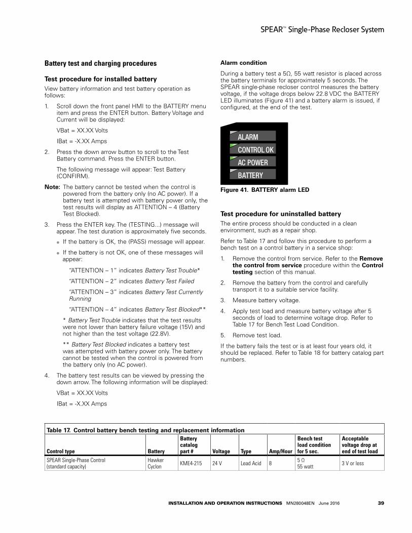
39
SPEAR™ Single-Phase Recloser System
INSTALLATION AND OPERATION INSTRUCTIONS MN280048EN June 2016
Battery test and charging procedures
Test procedure for installed batteryView battery information and test battery operation as follows:
1. Scroll down the front panel HMI to the BATTERY menu item and press the ENTER button. Battery Voltage and Current will be displayed:
VBat = XX.XX Volts
IBat = -X.XX Amps
2. Press the down arrow button to scroll to the Test Battery command. Press the ENTER button.
The following message will appear: Test Battery (CONFIRM).
otee:N The battery cannot be tested when the control is powered from the battery only (no AC power). If a battery test is attempted with battery power only, the test results will display as ATTENTION – 4 (Battery Test Blocked).
3. Press the ENTER key. The (TESTING...) message will appear. The test duration is approximately five seconds.
If the battery is OK, the (PASS) message will appear.
If the battery is not OK, one of these messages will appear:
“ATTENTION – 1” indicates Battery Test Trouble*
“ATTENTION – 2” indicates Battery Test Failed
“ATTENTION – 3” indicates Battery Test Currently Running
“ATTENTION – 4” indicates Battery Test Blocked**
* Battery Test Trouble indicates that the test results were not lower than battery failure voltage (15V) and not higher than the test voltage (22.8V).
** Battery Test Blocked indicates a battery test was attempted with battery power only. The battery cannot be tested when the control is powered from the battery only (no AC power).
4. The battery test results can be viewed by pressing the down arrow. The following information will be displayed:
VBat = XX.XX Volts
IBat = -X.XX Amps
Table 17 . Control battery bench testing and replacement information
Control type Battery
Battery catalog part # Voltage Type Amp/Hour
Bench test load condition for 5 sec.
Acceptable voltage drop at end of test load
SPEAR Single-Phase Control (standard capacity)
Hawker Cyclon KME4-215 24 V Lead Acid 8 5 Ω
55 watt 3 V or less
Alarm condition
During a battery test a 5Ω, 55 watt resistor is placed across the battery terminals for approximately 5 seconds. The SPEAR single-phase recloser control measures the battery voltage, if the voltage drops below 22.8 VDC the BATTERY LED illuminates (Figure 41) and a battery alarm is issued, if configured, at the end of the test.
Figure 41 .
DATA PORT
ENTER
EDITESC
BATTERYTEST
SUPER-VISORY
OFFNON
RECLOSE
HOT LINETAGTRIP
OFF
(LOCKOUT)
CLOSE
SPEAR Single-Phase Recloser Control
ON
ALTPROFILE
PHASE FAULT
ABOVE MIN TRIPALARM
CONTROL OK
AC POWER
BATTERY
LOCKOUT
OPEN
CLOSED
→*SETTINGS *SEQUENCE OF EVENTS *METERING
BATTERY alarm LED
Test procedure for uninstalled batteryThe entire process should be conducted in a clean environment, such as a repair shop.
Refer to Table 17 and follow this procedure to perform a bench test on a control battery in a service shop:
1. Remove the control from service. Refer to the Remove the control from service procedure within the Control testing section of this manual.
2. Remove the battery from the control and carefully transport it to a suitable service facility.
3. Measure battery voltage.
4. Apply test load and measure battery voltage after 5 seconds of load to determine voltage drop. Refer to Table 17 for Bench Test Load Condition.
5. Remove test load.
If the battery fails the test or is at least four years old, it should be replaced. Refer to Table 18 for battery catalog part numbers.
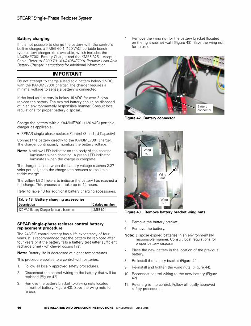
40
SPEAR™ Single-Phase Recloser System
INSTALLATION AND OPERATION INSTRUCTIONS MN280048EN June 2016
Battery chargingIf it is not possible to charge the battery with the control’s built-in charger, a KME5-60-1 (120 VAC) portable bench type battery charger kit is available, which includes the KA43ME7001 Battery Charger and the KME5-325-1 Adapter Cable. Refer to S280-79-14 KA43ME7001 Portable Lead Acid Battery Charger Instructions for additional information.
IMPORTANTDo not attempt to charge a lead acid battery below 2 VDC with the KA43ME7001 charger. The charger requires a minimal voltage to sense a battery is connected.
If the lead acid battery is below 19 VDC for over 2 days, replace the battery. The expired battery should be disposed of in an environmentally responsible manner. Consult local regulations for proper battery disposal..
Charge the battery with a KA43ME7001 (120 VAC) portable charger as applicable:
SPEAR single-phase recloser Control (Standard Capacity)
Connect the battery directly to the KA43ME7001 charger. The charger continuously monitors the battery voltage.
otee:N A yellow LED indicator on the body of the charger illuminates when charging. A green LED indicator illuminates when the charge is complete.
The charger senses when the battery voltage reaches 2.27 volts per cell, then the charge rate reduces to maintain a trickle charge.
The yellow LED flickers to indicate the battery has reached a full charge. This process can take up to 24 hours.
Refer to Table 18 for additional battery charging accessories.
Table 18 . Battery charging accessoriesDescription Catalog number120 VAC Battery Charger for spare batteries KME5-60-1
SPEAR single-phase recloser control battery replacement procedure The 24 VDC control battery has a life expectancy of four years. It is recommended that the battery be replaced after four years or if the battery fails a battery test (after sufficient recharge time) - whichever occurs first.
otee:N Battery life is decreased at higher temperatures.
This procedure applies to a control with batteries.
1. Follow all locally approved safety procedures.
2. Disconnect the control wiring to the battery that will be replaced (Figure 42).
3. Remove the battery bracket two wing nuts located in front of battery (Figure 43). Save the wing nuts for re-use.
4. Remove the wing nut for the battery bracket [located on the right cabinet wall] (Figure 43). Save the wing nut for re-use.
Figure 42 .
Battery connector
Battery connector
Figure 43 .
Wing nut
Wing nut
Wing nut
Remove battery bracket wing nuts
5. Remove the battery bracket.
6. Remove the battery.
otee:N Dispose expired batteries in an environmentally responsible manner. Consult local regulations for proper battery disposal.
7. Place the new battery in the location of the previous battery.
8. Re-install the battery bracket (Figure 44).
9. Re-install and tighten the wing nuts. (Figure 44).
10. Reconnect control wiring to the new battery (Figure 42).
11. Re-energize the control. Follow all locally approved safety procedures.
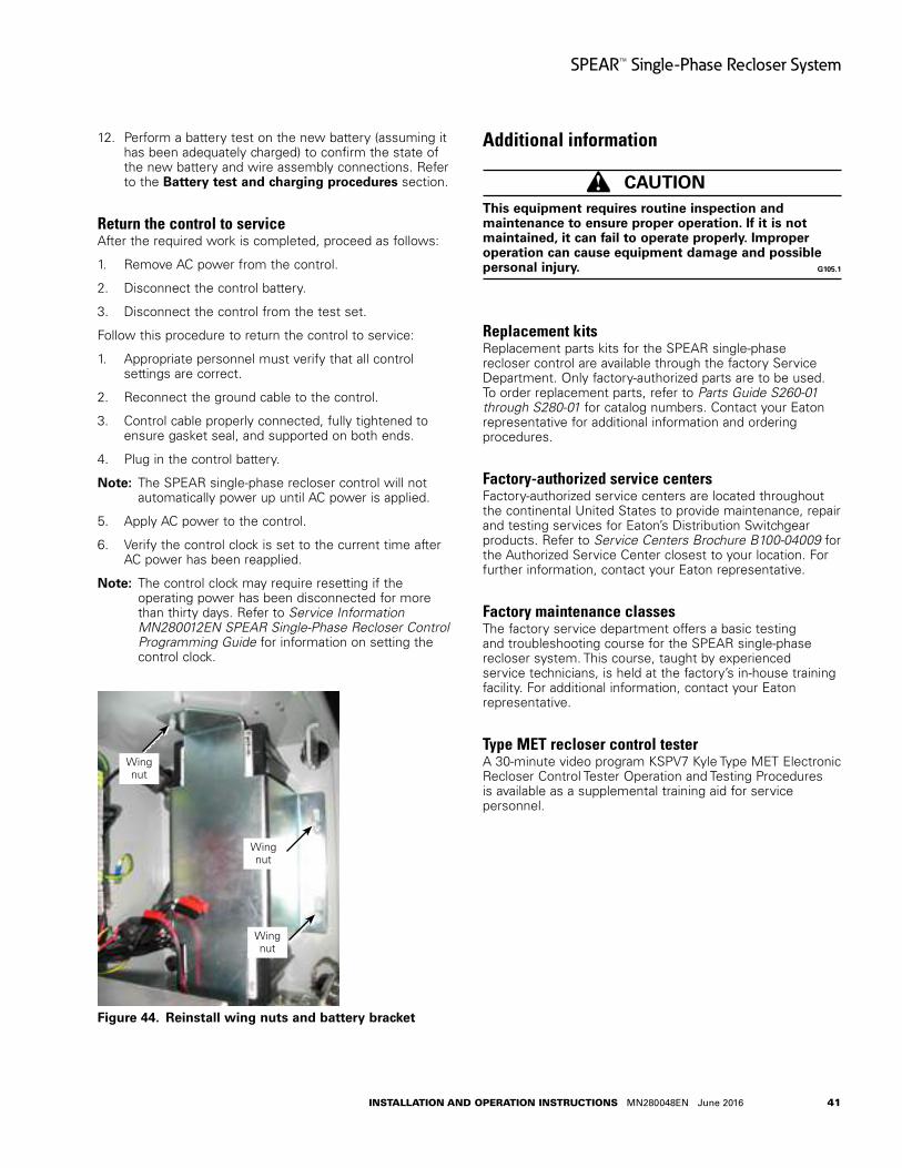
41
SPEAR™ Single-Phase Recloser System
INSTALLATION AND OPERATION INSTRUCTIONS MN280048EN June 2016
12. Perform a battery test on the new battery (assuming it has been adequately charged) to confirm the state of the new battery and wire assembly connections. Refer to the Battery test and charging procedures section.
Return the control to serviceAfter the required work is completed, proceed as follows:
1. Remove AC power from the control.
2. Disconnect the control battery.
3. Disconnect the control from the test set.
Follow this procedure to return the control to service:
1. Appropriate personnel must verify that all control settings are correct.
2. Reconnect the ground cable to the control.
3. Control cable properly connected, fully tightened to ensure gasket seal, and supported on both ends.
4. Plug in the control battery.
otee:N The SPEAR single-phase recloser control will not automatically power up until AC power is applied.
5. Apply AC power to the control.
6. Verify the control clock is set to the current time after AC power has been reapplied.
otee:N The control clock may require resetting if the operating power has been disconnected for more than thirty days. Refer to Service Information MN280012EN SPEAR Single-Phase Recloser Control Programming Guide for information on setting the control clock.
Figure 44 .
Wing nut
Wing nut
Wing nut
Reinstall wing nuts and battery bracket
Additional information
CAUTIONThis equipment requires routine inspection and maintenance to ensure proper operation . If it is not maintained, it can fail to operate properly . Improper operation can cause equipment damage and possible personal injury . G105 .1
Replacement kitsReplacement parts kits for the SPEAR single-phase recloser control are available through the factory Service Department. Only factory-authorized parts are to be used. To order replacement parts, refer to Parts Guide S260-01 through S280-01 for catalog numbers. Contact your Eaton representative for additional information and ordering procedures.
Factory-authorized service centersFactory-authorized service centers are located throughout the continental United States to provide maintenance, repair and testing services for Eaton’s Distribution Switchgear products. Refer to Service Centers Brochure B100-04009 for the Authorized Service Center closest to your location. For further information, contact your Eaton representative.
Factory maintenance classesThe factory service department offers a basic testing and troubleshooting course for the SPEAR single-phase recloser system. This course, taught by experienced service technicians, is held at the factory’s in-house training facility. For additional information, contact your Eaton representative.
Type MET recloser control testerA 30-minute video program KSPV7 Kyle Type MET Electronic Recloser Control Tester Operation and Testing Procedures is available as a supplemental training aid for service personnel.

Eaton1000 Eaton BoulevardCleveland, OH 44122United StatesEaton.com
Eaton’s Power Systems Division2300 Badger DriveWaukesha, WI 53188United StatesEaton.com/cooperpowerseries
© 2016 EatonAll Rights ReservedPrinted in USAPublication No. MN280048EN June 2016KA20480750 REV00
Eaton is a registered trademark.
All trademarks are property of their respective owners.
For Eaton's Cooper Power series product information call 1-877-277-4636 or visit: www.eaton.com/cooperpowerseries.