Embed Size (px)
Citation preview

2004 Specifications CSJ 0086-14-025
SPECIAL SPECIFICATION 8375
LED Dynamic Message Sign
1. Description. Furnish and install Light Emitting Diode (LED) Dynamic Message Signs (DMS) with the following minimum specifications: full character matrix high density display capable of displaying 3 rows of nominal 18-inch characters, 18 characters wide. Ensure the sign is capable of displaying character fonts approved for DMS use by the Manual on Uniform Traffic Control Devices (MUTCD) latest revision and its accompanying reference documents. Furnish, install, integrate and test all electronic components and electrical systems, equipment, cabinets, software and cabling for each DMS.
2. Materials. Provide solid state display elements and modules. No mechanical or electromechanical elements or shutters will be accepted. Ensure DMS is suitable for operations in exposed outdoor locations.
A. General Requirements. Furnish new, corrosion resistant materials. This specification describes the minimum requirements of a complete LED DMS for a character matrix with 18 inch characters. The principal components of the DMS include the Sign Housing, Sign Controller and Cabinet. Furnish, assemble, fabricate, and install materials as shown on the plans, the requirements of this item, and the pertinent requirements of the following: • TxDOT Special Specification, “Electronic Components” • TxDOT Special Specification, “Testing, Training, Documentation, Final
Acceptance, and Warranty” and • NEMA TS-2 Section 2 (environmental requirements), latest edition • NEMA TS-4, latest edition • NEMA Enclosure Standard 250 (NEMA Type 3R outdoor enclosures)
Furnish and install the vendor diagnostic software on all central controller, laptops and maintenance devices. Furnish and install the following equipment for each DMS field site as shown on the plans.
• LED DMS • Sign controller • DMS mounting brackets and hardware • Cabling • Field equipment • Modems or data service units • Pole mounted ground cabinet
1-30 8375 07-09

B. Terminology. Due to the varying definitions used in DMS technology, this section defines specific terms as they apply to this Special Specification.
1. Sign: The sign housing and its contents.
2. Sign Controller: A device located in close proximity to the DMS which controls the text messages being displayed. The sign controller receives NTCIP commands via a serial and Ethernet port (as shown in the plans). The sign controller manages the operation of the DMS.
3. Pixel: Any of the small discrete elements that, when arranged in a 5x7 matrix, create a character. A pixel contains a cluster of LED’s.
4. Pitch: Distance measured from center to center of adjacent pixels. This distance can be measured both horizontally and vertically.
5. Module: A matrix of equally spaced pixels.
6. Message: The text or graphical information being displayed to the motorist. Messages may be more than one page of information.
7. Display: The visible face of the sign.
8. Neutral State: Sign is blank or a predefined message is displayed.
9. DMS: The display and the housing surrounding the display.
10. DMS Control Software: Software used in the sign controller to control the display.
11. Central Controller: Central control software being run at the TMC or on another computer which communicates with the sign controller to obtain status or manipulate the operation of the DMS.
12. Ventilation System: Consists of fans, filters, and temperature sensors that provide cooling air for maintenance personnel only.
C. DMS. The LED DMS must enable the display of text, consisting of strings of alphanumeric and other characters. Assemble all required components from a common set of modules.
When shown in the plans, provide flashing beacons as an integral part of the DMS.
1. Physical Characteristics
a. General Construction. Ensure the completed sign presents a clean and neat appearance. Poor workmanship is cause for rejection of the sign. Protect equipment within each sign from moisture, dust, dirt, insects and corrosion.
The sign must be designed for a minimum life of 20 yrs.
2-30 8375 07-09

Construct the sign housing skin with 1/8 in. thick 5052-H32 aluminum alloy or an approved equal. Use aluminum alloy 6061-T6 or 6063-T5 for framing structural members or an approved equal. Use an inert gas process to continuously welded seams.
The structural framing members shall be welded for a walk-in housing. The housing must be made of aluminum extrusions that are welded or assembled together. The sheet aluminum used on the sides, back, top and bottom of the sign housing shall be 1050-H4 alloy or an approved equal.
Securely clamp cables in sign housings with cable attachments. Do not use adhesive attachments.
Equip each sign housing with at least three 15 A. 120 V (±10%) grounded GFI protected duplex electrical receptacles. Locate 1 receptacle at each end of the sign housing and 1 at the center of the sign housing. GCFI must be re-settable from the inside of the housing.
Design the sign to withstand sustained AASHTO wind loadings without permanent deformation. Calculate maximum wind loadings at 100 MPH with gusts up to 120 MPH unless otherwise shown on the plans. The sign shall consist of a sign housing, contrast shields, optical systems, internal wiring, terminal strips for interconnecting wire, duplex outlets, and photo sensors. Communication jacks, static message panels, heating strips, temperature sensors, and other optional equipment shall be supplied as called for in the plans and/or this special specification. Any electronic or electrical device installed in the housing shall be mounted for easy access for maintenance personnel. The DMS Equipment shall be modular in design so that it is not necessary for a technician to remove or replace discrete components in the field to analyze and/or correct a failure.
Ensure the performance of the sign will not be impaired due to continuous vibration caused by wind, traffic or other factors. This includes the visibility and legibility of the display.
Ensure the system and associated circuitry conforms to the requirements in Federal Communications Commission (FCC) Title 47, Sub Part B, Section 15; regulations concerning the emission of electronic noise.
Ensure the presence of ambient magnetic or electromagnetic fields, including those created by any components of the system, will have no deleterious effect on the performance of the system.
Ensure the system does not conduct or radiate signals, which will adversely affect other electrical or electronic equipment including, but not limited to, other control systems, data processing equipment, audio, radio and industrial equipment.
b. Walk-In Housing
3-30 8375 07-09

Walk-in housing dimensions and total weight will be shown on the plans. Provide a rain-tight and weather-tight walk-in housing.
Inside the sign housing, independently protect all 120 VAC service lines by a thermomagnetic circuit breaker at the sign housing entry point. Locate all 120 VAC wiring in conduit, pull boxes, raceways, or control cabinets as required by the NEC. Do not expose any 120 VAC wiring to the inside or outside of the sign housing. The sign housing is not a raceway or control cabinet.
The DMS housing must be built to guaranty structural integrity and shall comply with the latest requirements of AASHTO LTS-4-12, Standard Specifications for Structural Supports for Highway Signs, Luminaires, and Traffic Signals, latest Edition. At minimum, the DMS housing, structural frame, face covering, and mounting members shall be capable of withstanding the environmental loadings specified in AASHTO, sub-clauses 3.8.5 and 3.8.6.
(1) Weather-tight Enclosure
All front face windows and access doors shall be sealed or have a gasket to prevent water, dirt and insects from entering the interior. Screened ventilation louvers and drains shall be included to eliminate moisture buildup due to condensation.
The DMS housing supplied shall have a NEMA type 3R rating.
(2) Exterior Housing Finish
To minimize heat build up, the back, top, bottom and sides shall have a maintenance free, natural aluminum finish.
Front face non-transparent surfaces outside the viewing cones of pixels shall be covered by a black adhesive as approved by Texas DOT to increase contrast ratio and eliminate reflection.
No painted surfaces will be allowed
(3) Mounting
Use 6061-T6 aluminum alloy extrusions or an approved equal, 3/16 in. minimum thickness, for exterior mounting assemblies. The method of attachment between the sign and structure must be closely coordinated with the DMS Manufacturer before the sign or the structure is released for manufacturing.
The walk-in sign housings shall be equipped with slotted aluminum extrusions, attached to the back of the sign in the horizontal position.
Each horizontal extrusion shall accept DMS Manufacturer supplied stainless steel hardware and aluminum friction clamps that will attach to contractor supplied “I-beams”.
4-30 8375 07-09

This configuration shall allow the sign mounting interface to be adjustable vertically and horizontally.
Design the mounting fixtures and structures for a horizontal angular adjustment to optimize viewing angle as directed. Submit dated, signed, and sealed shop drawings by a Licensed Professional Engineer for mounting fixture and structure designs and modifications before fabrication to be approved by TxDOT.
(4) Tilting Each DMS must be visible without any need to tilt the front face or housing toward the road. Vertical viewing angle from each pixel must be 10° degrees toward the road.
(5) Accessibility
Each door shall be sealed to prevent the elements from entering, and shall have at least two locking points to keep unauthorized persons from accessing the interior of the DMS Sign. In addition, each door shall be provided with rigid, telescopic, retention device, to keep and hold the door in the open position at 90°. Any access panels shall be limited in size so they may be opened or closed by one person and shall have a gasket and sealed to prevent the elements from entering (when closed) and shall include locks to prevent unauthorized access. Access panels shall be supported in their open position by multiple self-locking retaining devices that thoroughly support the panel assembly in the open position in 40mph (64 km/h) wind.
a) Walk-In Access Walk-in housings shall allow access to all components from within the sign.
A non-skid aluminum floor shall be provided inside the sign housing so that a maintenance person can walk to either end of the interior with a constant minimum of 24- inches (61_cm) of aisle space to perform his or her duties.
1) Access door
Provide a 3 point lockable aluminum access door at the end of the housing. Provide a 6 ft. 8 in. by 2 ft. access door minimum.
Fit the door with a handle operated locking mechanism, closed cell neoprene gasket, and stainless steel hinges.
5-30 8375 07-09

Provide a heavy-duty, industrial-strength, 3 point, dead-bolt, center-case locking mechanism with a zinc finish. Install a heavy-duty, industrial-strength handle with a zinc finish on the inside of the door and a chrome finish on the outside of the door. Include a device to hold the door open at 90°. The outside handle must be pad lockable. When open, the door shall be sturdy enough to withstand wind gusts of 40mph (64.4 km/h) and not be deformed. A door handle must be provided outside and inside the housing so that a person with no key or no tools cannot be trapped inside the housing.
Walkways and/or step-over thresholds must be marked in accordance with OSHA regulations.
A door switch shall be provided and wired to the DMS controller so that the position of the door (open or closed) can be monitored. This information shall be transmitted to control center upon request.
(6) Work Area (Internal Walkway): Provide an interior sign housing with a minimum width of 2 ft. 10 in. and a non-obstructed interior walkway must be a minimum of 2 ft. (0.61m) wide and 6 feet (1.83m) high and the structural members shall not obstruct any movement of technicians inside the work area. Walkway shall extend the full length of the sign housing and finish all edges of the walkway grating to eliminate sharp edges or protrusions.
The sign floor shall be designed to avoid water retention. A minimum of four drainage holes, designed to prevent the entry of insects and the accumulation of dirt and moisture, shall be provided. The floor shall be designed to prevent the loss of any tools or materials by falling under the floor. If loss of tools under the floor is possible, then the floor must be either hinged or have removable sections which are easily handled by one person. The floor shall not obstruct the maintenance of any drainage system.
For signs manufactured with an adjustable tilt, the internal floor shall have a fixed slope of four degrees toward the back of the sign to minimize worker fatigue.
(7) Internal Lighting and Electrical Outlets
A minimum of one 60W fluorescent light every 8 feet (2.44m) of housing must be provided. The light assembly shall operate from -29ºF (-34°C) to +165ºF (+74°C) and shall be protected by a cage. A manual timer having a maximum ON time of two hours must control all lights and must be placed near the entry door.
A minimum of least three 15 A. 120 V (±10%) grounded GFI protected duplex electrical receptacles. Locate 1 receptacle at each end of the sign
6-30 8375 07-09
housing and 1 at the center of the sign housing no more than 3 ft. above the walkway. GCFI must be re-settable from the inside of the housing.
(8) Ventilation System The ventilation system for a walk-in housing shall only be required for the comfort and safety of maintenance personnel. This system shall be unnecessary for cooling the electronics, components and assemblies.
A positive pressure forced-air ventilation system shall be designed to exchange at least two (2) volumes of air per minute. Both the intake and exhaust ports shall be filtered with high quality, durable, electrostatic air filters.
A manual override timer-switch with 2- hour duration shall be installed near the entrance of the Walk-In to activate the air venting system.
The transfer and absorption of heat due to solar radiation shall be minimized by the design of the housing and front face, to minimize the power consumption and maintenance needs and to maximize the operability and longevity of the sign.
Ductwork systems shall not be required or allowed, due to added weight and internal clutter.
The DMS sign housing shall incorporate a closed loop internal air circulation system that moves air around and among the components.
Air inlets and outlets for the ventilation system must prevent water from entering the sign housing interior.
The DMS controller shall monitor all the temperature and humidity sensors and perform the correct action when required. Temperature and humidity sensors shall be solid state.
The central computer and the laptop computers must have the ability to read all temperature readings from the sign controller.
Heaters must be used to control moisture and to prevent condensation (i.e. frost, snow, ice, etc.) from accumulating on the front face.
Hydrometer(s) must be installed inside the sign.
(9) Condensation and/or Fog Prevention.
Condensation and/or fog prevention of the facing of the sign and electronic components must be provided.
(10) Humidity Control
Provide heaters to eliminate moisture and condensation that could accumulate on the front of the sign. These shall operate at 120 VAC and
7-30 8375 07-09

shall be managed by the sign controller. Power consumption for the heaters shall be no greater than 150-watts per square meter of display area (not including contrast shields).
The controller shall monitor the temperature and humidity of the sign housing plus ambient external temperature. This information shall be stored in the controller’s log file and be transmitted to the Central Computer upon request. In the event that the temperature goes above a selectable limit (set at 165°F (+74°C), an alarm must be sent back to the Central Computer and the sign shall be switched off.
The sign controller must use these readings in an algorithm that turns on the condensation and/or fog prevention system and the fans at the appropriate times to reduce both frost on the face of the sign and condensation on the display modules and other electronic circuitry.
2. Electronics and Electrical
a. Display Modules. Assemble display modules consisting of nominal 18 in. high characters.
Each display module at a minimum must include an LED display circuit board containing 35 LED pixels arranged into a 5 X 7, 18 in. high character matrix. All display modules provided by one manufacturer must be interchangeable throughout that manufacturer’s sign system. Ensure the LED DMS consists of sufficient modules to provide the number of lines and rows of characters as shown on plans.
Ensure that LED modules not become loose or fall off during handling or due to vibrations.
Ensure the replacement of a complete display module is possible without the use of any tools. Interconnect modules through keyed connectors only to preclude improper hookups.
b. Message. Ensure characters displayed adhere to all MUTCD and AASHTO DMS standards. Ensure the brightness of the characters displayed on the sign provide optimum legibility during all lighting conditions.
c. Pixel Optical Characteristics. The optical system shall provide a uniform display across the sign, so that there is no visible difference in luminous intensity from any one pixel to another pixel, under any brightness level.
The display color shall be yellow and all pixels shall have a 30° viewing angle.
8-30 8375 07-09

Average character legibility for 30° viewing angle shall be in accordance with TABLE I:
NOMINAL CHARACTER HEIGHT (Inches) PITCH
TYPICAL LEGIBILITY DISTANCE
Feet (Meters) 18” 2.57” (65.3 mm) 1,000’ (305 m)
TABLE I - CHARACTER SIZE AND LEGIBILITY DISTANCE
(1) Contrast Ratio Contrast Ratio, Cr= (Lon-Loff) / Loff: Where:
Cr = contrast ratio
Lon = measured luminance from the display with the pixels active or on, at the specified sign illuminance.
Loff = measured luminance from the display with the pixels inactive or off, at the specified sign luminance.
Based on this formula, the DMS shall meet a contrast ratio of at least 12, when measured on-axis (0° horizontal and 0° vertical in relation to the center of the sign face) under any illumination lower or equal to 40 000 lux by a solar simulator.
The DMS manufacturer must submit a test certificate from an independent laboratory to certify compliance with this requirement.
(2) Cone of Vision The cone of vision for various character heights as shown in TS 4 Section 5.3.3.2, Table 5-7, shall be in accordance with Table II below.
CHARACTER HEIGHT NEMA Type Class (NEMA Table 5-7)
18” 30 degrees
TABLE II – CONE OF VISION
The DMS manufacturer must submit a test certificate from an independent laboratory to certify compliance with this requirement. An LED component manufacturer certificate will not be enough since the test must take into consideration the mounting of display boards within the sign and the front face.
9-30 8375 07-09
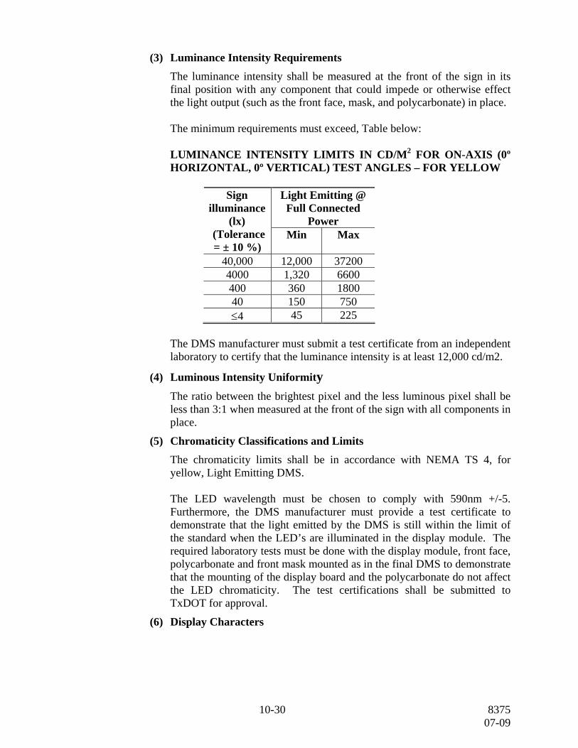
(3) Luminance Intensity Requirements
The luminance intensity shall be measured at the front of the sign in its final position with any component that could impede or otherwise effect the light output (such as the front face, mask, and polycarbonate) in place.
The minimum requirements must exceed, Table below:
LUMINANCE INTENSITY LIMITS IN CD/M2 FOR ON-AXIS (0º HORIZONTAL, 0º VERTICAL) TEST ANGLES – FOR YELLOW
Light Emitting @
Full Connected Power
Sign illuminance
(lx) (Tolerance = ± 10 %)
Min
Max
40,000 12,000 37200 4000 1,320 6600 400 360 1800 40 150 750 ≤4 45 225
The DMS manufacturer must submit a test certificate from an independent laboratory to certify that the luminance intensity is at least 12,000 cd/m2.
(4) Luminous Intensity Uniformity The ratio between the brightest pixel and the less luminous pixel shall be less than 3:1 when measured at the front of the sign with all components in place.
(5) Chromaticity Classifications and Limits The chromaticity limits shall be in accordance with NEMA TS 4, for yellow, Light Emitting DMS.
The LED wavelength must be chosen to comply with 590nm +/-5. Furthermore, the DMS manufacturer must provide a test certificate to demonstrate that the light emitted by the DMS is still within the limit of the standard when the LED’s are illuminated in the display module. The required laboratory tests must be done with the display module, front face, polycarbonate and front mask mounted as in the final DMS to demonstrate that the mounting of the display board and the polycarbonate do not affect the LED chromaticity. The test certifications shall be submitted to TxDOT for approval.
(6) Display Characters
10-30 8375 07-09

Display the upper and lower case alphanumeric characters over the complete height of the character matrix. Submit character fonts for approval. The sign must be able to display the font as follows:
The standard font is 5 x 7 pixels.
• Condensed Font (4 x 7 pixels per character)
• Expanded Font (6 x 7 pixels per character)
• Double Stroke Font (7 x 7 pixels per character)
Ensure the brightness and color of each pixel are uniform over the entire face of the sign in all lighting conditions. Non-uniformity of brightness or color over the face of the sign under these conditions will be cause for rejection of the sign. Full Character matrix sign shall be able to display all above fonts as defined by NTCIP 1203.
A) Optical Components
1) General (Pixel Spacing) For character matrix signs, the horizontal separation between two characters shall be a minimum of 2 pixels.
For character matrix signs, the vertical separation between two characters shall be a minimum of 1/2 of the character height. a) Pixel Spacing
The horizontal and vertical pixel spacing (pitch) shall be equal and shall be in accordance to the sizes as shown below.
Character matrix sign:
• 18 inch character height, line or character matrix – 2.57 inches ( 65.3 mm)
2) Interchangeability of Character Display Boards
No special tools or software shall be required to install, change or relocate a character display board.
(7) Display Change Time The display shall change from one page of text to another in less than 100 ms, based on an OFF time of zero seconds. Changes from one message to another shall take place so that the motorist visualizes only the complete and intended message on the sign face, at any one time. No other message
11-30 8375 07-09

interpretations other than the intended message shall be possible during transitions from one message to another. All lines of text shall energize and de-energize simultaneously.
d. LED Light System. Each LED shall emit a true yellow color per the chromaticity classifications in the Display Properties Section. No combinations of different colored LED’s will be allowed to create yellow.
All LED’s used in a sign shall come from the same LED component manufacturer and shall be non-tinted, non-diffused, high intensity, AllnGaP technology.
For uniformity of messages, all the LED's in the sign shall be selected by intensity and by color so that the source of the LED can only be from two adjacent bins of the LED manufacturer for each sign.
A label must be on each display board indicating the intensity, color bin, and detailed reference of the LED used.
The hardware design of the LED driver circuitry shall be such that the LED current shall be hardware restricted so it can never exceed the 75 % of Maximum Forward Current as defined by the LED Manufacturer. These criteria must be met even if there is a software failure in the system.
Pulsing of LED's with instantaneous current in excess of the Maximum Forward Current is not allowed under any condition.
To minimize the effects of long-term light output degradation the Nominal Forward Current shall be changeable at the controller level from 0 to 100% of the Maximum Forward Current.
The change of brightness must occur simultaneously on all characters in the sign.
To provide a uniform display after replacing a display board with a new one, the display board must be equipped with a rotary switch or be software configurable so the user may locally adjust the brightness of the “new” character, to the same brightness as the rest of the sign.
The minimum operating temperature range of the LED's, as defined by the LED manufacturer, shall be -40º C to +100º C.
12-30 8375 07-09

(1) Character Display Board
Each character display board shall consist of only one electronic assembly that contains all of the LED’s, LED drivers, memory, microcontroller and network elements to control the LED's for only that character.
All like-size characters shall be fully interchangeable within a sign.
The replacement of a character display board shall be possible without the use of any tools, drawings or diagnostic equipment.
To insure uniformity across the sign, all LED’s shall be mounted so their mechanical axis is perpendicular to the sign face.
All the connections between boards shall be made with rugged, positive locking, quick release, and coded connectors. Their size and shape shall be such that they are easy to manipulate in any maintenance situation.
At a minimum each display board shall contain one power and one data connector. To avoid the risk of misalignment and for other benefits, only surface mounted LED’s are allowed. To minimize heat problems, no standoffs that hold the base of the LED’s will be allowed. The use of other type of LEDs will not be permitted and will be a sufficient reason for DMS rejection.
Provide 2 separate types of pixel status feedback to the central controller from the local sign controller, including a pixel test and a pixel read.
(2) Pixel Status
A) Pixel Test: Test the full operational status of each pixel and report the status to the local sign controller. Upon request from central, identify a list of modules with defective pixels. The pixel test may briefly disturb the displayed message for less than 0.5 sec.
B) Pixel Read: Report back to the local controller which pixels are on/off. Upon request from central controller, provide a list of which pixels are on/off. Pixel read shall not interfere with the displayed message.
(3) Photoelectric Sensor Devices
Provide photocells that cause automatic light intensity adjustment. Install 3 photocells on the sign. Install 1 photocell to measure the “DAY” and “NIGHT” threshold. Install the other 2 on the front of the sign to measure the “OVERBRIGHT” threshold.
13-30 8375 07-09

Ensure brightness may be manually adjustable from the local sign controller in 1% increments. Enable brightness control to be returned to automatic from the sign controller, laptop or the central controller. Easily removable photo sensors shall have a minimum range between 2 and 100, 000 lux.
The DMS Controller shall automatically control the dimming, with a minimum of 16 brightness levels.
The system shall provide the ability to adjust the relationship between the degree of dimming and external light conditions, and shall ensure that the luminance output of the sign provides the maximum luminance for the background lighting, without eye discomfort to viewers.
The dimming system shall not be affected by variations in the AC supply voltage and shall maintain a constant light output at all brightness levels.
If flashers are provided their brightness level must be adapted at the same time as the other parts of the sign and flashers must flash simultaneously.
(4) Electronic Components. Provide electronic components in accordance with Special Specification, “Electronic Components.” Provide commercially available, easily accessible, replaceable, and individually removable using conventional electronics repair methods for all electronic components, except printed circuit boards. All workmanship must comply with ANSI/IPC-A-610B Class 2 titled “Acceptability of Electronic Assemblies”, ANSI/IPC-7711 titled “Rework of Electronic Assemblies” and ANSI/IPC-7721 titled “Rework and Modification of Printed Boards and Electronic Assemblies.” Refer to: IPC, 2215 Sanders Road, North Brook, IL 60062-6135.
All components must be of such design, fabrication, nomenclature, or other identification to be purchased from a wholesale electronics distributor, or from the component manufacturer, except for printed circuit board assemblies.
Design circuits such that all components of the same generic type, regardless of manufacturer, must function equally in accordance with the specifications.
Use individually replaceable discrete components, such as resistors, capacitors, diodes, transistors, and integrated circuits. Arrange components so they are easily accessible for testing and replacement.
14-30 8375 07-09
Capacitors: The DC and AC voltage ratings as well as the dissipation factor of a capacitor all exceed the worst case design parameters of the circuitry by 50%.
Support capacitors, which can be damaged by shock or vibration, mechanically by a clamp or fastener.
Provide capacitor encasements resistant to cracking, peeling, and discoloration.
Resistors: Resistors must be within 5% of tolerance over the specified temperature range. Any resistor operated in excess of 50% of its power rating must have an adequate heat sink.
Semiconductor Devices: Use standard type listed by EIA transistors, integrated circuits, and diodes and clearly identified.
a). Mechanical Requirements
1) All assemblies shall be easily replaceable but must be securely mounted within the sign or the controller cabinet.
b). Printed Circuit Boards
1) Design Printed Circuit Board (PCB) that components may be removed and replaced without damage to boards, traces, or tracks.
2) Use FR-4 0.062 in. material, copper clad inter component wiring with a weight of 2 oz. per sq. ft.. Jumper wires will not be permitted, except from plated-through holes to component. The maximum number of jumper wires allowed per circuit board is 2. Finish all PCBs with a solder mask and a component identifier silk screen.
3). Conformal coat all PCB’s, except for the LED motherboard, power supply PCBs and controller PCBs, with a 0.010 in. (10 mil) thick silicone resin conformal coat. Conformal coat The LED motherboards, except at the pixels on the front of the PCB, with a 0.010 in. (10 mil) thick silicone resin conformal coat. Use coating material that complies with military specification: MIL-I-46058C Type SR.
c). Cabinet Wiring 1) The cabinet wiring shall be neat and clean. A single circuit breaker or disconnect shall be capable of turning all equipment OFF (DMS Sign and controller cabinet) and shall comply with NEC.
15-30 8375 07-09
(5) Communication
The sign controller must be addressable by the DMS Master Controller via the communications system and in accordance with Special Specification “National Transportation Communications for ITS Protocol for Dynamic Message Signs.”
Provide each DMS sign controller with error detection and reporting features, utilized to guard against incomplete or inaccurate transmission. These must include: • Cyclic redundancy checking of all data received from the DMS
Master Controller, with positive acknowledgment for all valid transmissions.
• Status monitoring for communication line malfunction or break. • Content validation of all received transmissions for logic or data
errors.
Use point-to-point or multi point communication line circuits and full duplex asynchronous data transmission at the rate directed by the Engineer. Provide all necessary modems at each location.
Assign a unique address for each sign controller within the circuit to which the sign is connected. Encode all data transmitted between the DMS Master Controller and the DMS sign controller in the ASCII representation using 1 start bit, 8 data bits, and 1 stop bit.
The communication profiles that must be supported by the controller are:
• PMPP – NULL, PPP – NULL, Ethernet – UDP/IP, RS-232
Data transmission shall support the following data formats: • Number Data Bits: 7 or 8-bits
• Parity: EVEN, ODD, NONE, MARK, or SPACE
• Number Stop Bits: 1-bit
Data transmission rate shall be configurable up to 115,200-BPS (bits per second using RS-422/485/232).
The DMS Controller shall be able to drive the sign a minimum distance of 1000 meters, without the need for an external modem or signal booster.
The controller shall include two (2) configurable Ethernet ports capable of communicating via TCP/IP or UDP/IP at 10 or 100 MB. Devices such as WiFi (802.11), routers, hubs, and if required, shall connect directly to the TCP/IP port.
Use EIA RS-232D serial interface to drive asynchronous modems for full duplex communication over dial up lines.
16-30 8375 07-09
Protect Dial-up or any hardwire multi-drop communication lines by two stages of transient voltage suppression devices including MOV’s and spark gap arrestor.
Tripping of each stage (or both if tripped simultaneously) of the surge protection must cause the sign controller to call central and report the error condition (for dialup operation). There must be an option that is either enabled or disabled and is selected and downloaded from the central controller to the sign controller. When this option is enabled, tripping of both stages of surge protection must disconnect the communication lines until the surge protection has been replaced. When this option is disabled, the sign must continue to function normally after both stages of surge protection are tripped.
Acquire and bear the charges of installing and connecting the dial-up telephone line.
The following interfaces must be available:
Two each: RS232, Ethernet 10/100 full duplex ports, RS485, USB port and
Four each: Digital outputs, Digital inputs
a) Communication (Protocols) The DMS Controller shall be capable of communicating using NTCIP 1203.
e. Display Diagnostics and Monitoring
1) LED Display Board On-site Monitoring
a) LED Display Board Status
Transmit/receive status between the board and DMS Sign Controller, whether or not the display board is properly powered, and if there is a fault on the display board.
b) LED Display Board Diagnostic Port A separate port shall be available for real time diagnostics and configuration of the display board, either in the sign, while the sign is operating, or outside of the sign for maintenance/repair. As a minimum, the following functions shall be available:
• Determine firmware version,
• Upload new version of firmware,
17-30 8375 07-09

• Determine the exact faulty pixel,
• Determine the address of the board,
2) LED Pixel Tests
The current flowing through each LED pixel shall be monitored and tested for open and short-circuit failure in the driving circuitry.
Further tests shall determine if the pixel is: • ON under Normal Conditions
• OFF under Normal Condition
• Abnormally ON or OFF
If a configurable number of faulty pixels are exceeded on any one module or on the entire sign display, the DMS Controller shall turn off the entire sign to prevent the display of an incomplete or erroneous message.
To detect faulty pixels, it is necessary to activate all the pixels during a pixel test. The pixel test shall be performed over a configurable period of time, or when requested by the Central Computer, Portable Maintenance Computer, or Local Control Panel. Testing of the pixels shall not create a visual disruption of more than 10 ms.
The controller shall store the address of any faulty pixels it detects through its testing.
3) LED Temperature Monitor
If DMS internal temperature exceeds a manufacturer defined threshold normally set to the highest working temperature, the DMS shall automatically shut-down. This threshold shall not be less than 165ºF.
3. Sign Face
All front face panel surfaces not directly in front of a light emitting pixel shall be masked with a black material to reduce glare and increase the contrast ratio. All light emitting pixels shall be protected by the use of a polycarbonate face that shall prevent the entry of water, dust, dirt and insects.
All pixels shall be designed in such a manner to eliminate reflective ghost effects from sunlight shining onto the front of the pixel.
An aluminum mask shall be utilized in front of the polycarbonate window to shade the LED pixels from the sun.
The DMS front face shall clearly display the LED message during exposure to the sun or wind.
Heaters shall be provided to reduce condensation and the accumulation of frost on the front face.
18-30 8375 07-09
Non-corrosive material shall be used.
Direct connection of dissimilar metals shall be avoided to eliminate galvanic action.
Ensure that the housing shall prevent any light leaks or reflection from the following:
• service lights or other internal lights shall not be visible from outside,
• reflective surfaces
• light leaks from behind the housing.
The housing of the DMS must be based on modular design. Each aluminum module must be continuously and individually welded and must be bolted to an adjacent module to form the housing. Vertical reinforcement must be provided between modules where necessary.
a) Contrast Shields (Border)
The front of the sign housing shall be completely surrounded by an aluminum contrast shield to improve legibility. This shield shall be bolted to the sign or be an integral part of the sign housing and shall mate so that no light leaks occur. The minimum width of the shields shall be 12 inches (304 mm) for 18 inch characters.
4. Environmental Behavior
Provide signs and associated field electronics that operate without any decrease in performance over the NEMA TS2 temperature range of –29°F to + 165°F with a relative humidity of up to 95%.
5. Power Requirements
Design the sign and its controller for use on the following:
a) Main Power Supply and Energy Distribution Either 120 VAC 60 Hz or 240 VAC 60 Hz (connected as single phase, Hot/Hot/Neutral/Ground) shall power the DMS Controller cabinet, which shall power the DMS. All other equipment shall be powered by 120 VAC, 60 Hz. To avoid the possibility of an error, all the components inside the sign and cabinet shall operate on the same voltage, (120 VAC), at any one time. Any transformer used to decrease the main voltage to 240 or 120 VAC will be supplied by the installing Contractor and housed in a separate enclosure. All work shall be in accordance with the National Electrical Code.
19-30 8375 07-09
Protection for the equipment shall be provided by a double-pole, 300 mA, ground-fault, thermal-magnetic breaker as well as by voltage surge protection, and lightning protection.
b) Surge Protection Device A minimum of two levels of surge protection shall be provided, one at the incoming power (parallel protection) and the second at the 120 VAC power distribution panel (series protection) sized in accordance with the load.
Ensure GFI devices protect all service outlets.
Ensure exposed cables are type XHHW and sized as required by the NEC.
c) Calculated Electrical Loads The installing Contractor shall gauge the electrical service wire to the cabinet to provide no more than a 5% reduction from no- load to full-load to calculate worst case consumption.
d) Stand-by Mode
During configurable periods, when the sign is not used to display a message, the DMS Controller must be able to enter a Stand-by Mode. The total power consumption of the sign and sign controller must be less than 25-watts. This does not include the modem, fans, heaters, lighting or other ancillary devices.
e) LED Power supplies
The LED power supply system shall be designed to illuminate every character on the sign with any allowable alphanumeric character at full power, at 74ºC. Power supplies shall be switching power supplies, which must be at least 80% efficient at nominal voltage, and include a self- resetting internal thermal protection device that switches off the output in case of an overload.
1) Redundancy
A redundant power supply system shall be mechanically and electrically independent of other power supply systems.
Under normal operation, the combined supplies must be able to source enough current to illuminate all the pixels at maximum current, at 74ºC.
In the event of a failure of one of the power supplies, the controller will detect the loss of power from the failed supplies. It shall switch and isolating that supply from the bus and will switch in a hot standby supply to take its place.
This power supply system shall allow all characters to be displayed on the sign without degradation.
20-30 8375 07-09
Ensure that the Controller notifies the Master Computer of the supply failure then next time it is polled.
f) Backup Power Uninterruptible Power Supplies (UPS) shall not be allowed. If backup power is required, an optional 12-volt maintenance free, trickle charged battery shall be installed to provide power to the CPU and modem for a minimum of 12 continuous hours after AC power interruption.
6) Field Equipment Cabinet. Submit shop drawings of the cabinet for approval by
the Engineer before installation.
a.) Ground or Pole Mounted Cabinet
The ground or pole mounted cabinet shall protect all the electronic components that are not located in the sign housing. Provide a gasket to seal the cabinet door facing, use a closed-cell neoprene gasket material that maintains its resiliency after exposure to the outdoor environment. The gasket must show no sign of rolling or sagging and must insure a uniform dust and weather resistant seal around the entire door facing (weatherproofed).
Design the pole/ground mounted cabinet and its sub-assemblies for continuous operation over an outside temperature range of –40°F to +165°F.
The cabinet shall comply with NEMA 250, Type 3R and shall be made of aluminum. The environmental characteristics of this specification shall be met without exhaust fans or air conditioning.
b.) Cabinet Components The pole or ground mount cabinet shall include the following.
• A 19-inch rack mounted microprocessor based DMS Controller (CPU)
• One permanently mounted communications cable
• Communication interface (modem)
• The main power supply and energy distribution system (main disconnect)
• One work lamp to illuminate the work area
• Continuous welded all exterior seams for cabinets and doors
• Smooth all exterior welds
• One 15 amp, 120 VAC GFCI protected duplex service outlet
• Lightning protection and terminations for the communication and control cables
21-30 8375 07-09

• Transient protection and RFI filtering on the incoming power lines
• Termination blocks for the control cables to and from the DMS sign
• Two identical keys for each cabinet
• Permanently mounted document holder
• Electrical drawings printed on water/tear-resistant material
• Provide a pullout shelf minimum of 10 X 10 in. shelf for the placement of a laptop computer and stored within the cabinet; Ensure shelf is capable of supporting a 20 lb. load
• Remote communications port - RS-232 plug-in connector for remote
communications with sign controller • Local communications port - RS-232 plug-in connection for the laptop
computer to communicate locally with sign controller
• A minimum of 4 ft long RS-232 cable to connect the laptop computer to the local communications port
c.) Cabinet Layout
The cabinet layout shall be modular in design, so that a maintenance person will be able to service the equipment with minimal training in changing major components such as boards or modular cable connectors.
• Each cable shall be individually and clearly labeled or coded with
permanent markings.
• Each point to point wire within the cabinet shall have permanent associative identification at both ends that correspond to the electrical drawings.
• All field cables shall be terminated into screw clamp terminal blocks that hold field wires logically grouped together by function.
• All modular connectors must connect to positive locking, quick disconnect terminal blocks so a complete connector may be easily disconnected with all its wires intact, without the use of tools.
• A shelf shall be provided for the use of a laptop.
• An internal light must be provided and illuminates automatically when the cabinet door is open.
• If required, cabinet shall be equipped with a battery and battery charger to power the controller and communication equipment upon failure of the main power.
22-30 8375 07-09
The physical appearance of the cabinet shall be neat and organized; utilizing either tie-wraps or wire channels to bundle wires. The DMS Controller cabinet shall be mounted on the ground or pole.
d.) Sign Controller.
Provide a sign controller with resident software with latest revision. Perform all communication, control, and feedback functions for the DMS through the local sign controller.
Program the sign controller to receive sign control commands from the master controller, transmit responses as requested to the master controller, and control sign operation and message displays in accordance with Special Specification, “National Transportation Communications for ITS Protocol for Dynamic Message Signs.”
Receive and send messages from the sign controller via a RS-232 modem as shown on the plans, transmitting and receiving data over dedicated, voice grade, lines. Alternatively, a switched line using a dial-up modem, conforming to Special Specification, “Dial-up Modem”, must be employed using a landline phone, as shown on the plans. Transmission speed will be directed.
Ensure the communications ports for the DMS shall act in accordance with all commands defined in the latest version of TxDOT Special Specification, “National Transportation Communications for ITS Protocol for Dynamic Message Signs.” The mode of operation determines which level of control governs the DMS message selection. The modes of operation include:
• Master- the DMS master [central controller] or attached local
laptop determines the appropriate message or test pattern. • Local - the sign controller is used to determine the appropriate
message, test pattern, sign configuration, and diagnostics. • Neutral - the reset/restore state for the display. Ensure neutral
state is user programmable and set as blank as a factory default. • Test – the test patterns provided by the manufacturer to determine
the functional and non-functional pixels.
Use a hardware watchdog circuit to provide automatic reset of sign controller in the event of failure.
Ensure the sign controller prevents improper information from being displayed in the event of a system malfunction.
23-30 8375 07-09

Operate the sign controllers such that malfunction of any sign controller results in a reset in neutral state and does not effect the operation of any other sign in the DMS system.
In the event of a communications failure with the DMS central controller, the local sign controller sets the sign to neutral after a defined number of minutes, as shown on the plans, unless communications are restored within this period.
The DMS Controller must be capable of operating with either of two voltages applied directly to the controller. The selection of voltage, 120 or 240 VAC, shall be selected by a switch. The controller shall be capable of receiving 12 VDC from a battery, in order to provide extended operation time in the event of a power failure, if required. The DMS Controller shall include a Central Processor Module having a battery backed clock calendar, with a 10-year backup, to record power failures and to perform all calculations and logical functions of the DMS Controller. When the display time of a message has expired, the controller must set the sign to neutral. A sign is considered neutral when the sign is blank or a default (predefined) message in sign controller memory is displayed. The sign controller must be able to put a self-updating time, temperature, date, or both display on the sign.
The sign controller must be capable of being remotely reset from the master controller.
The DMS Controller shall include one integrated Digital I/O board with 4 inputs and 4 outputs. The DMS Controller CPU shall be at least a 32-bit processor which operates at 400-MHz or greater. It shall have at least 20-MB of SRAM, and be capable of expanding its memory at least 16-MB more, via use of an industry standard “FLASH” memory card.
The DMS Controller shall have a screen and keyboard, located at the front of the controller for running diagnostics and controlling the sign.
The controller must be in a 19” rack and all connections must be in the front. There should be no need to access the back of the controller for any maintenance purpose and all indicators must also be in front.
1) Controller Functions The DMS Controller shall continuously monitor the display of the sign, independent of any external commands, and shall cause the signs to display all the appropriate characters. Through the DMS Controller, the
24-30 8375 07-09
sign shall be capable of displaying a single static message, a flashing message, or 5 alternating messages.
The DMS Controller shall command the sign to display characters and messages by turning the LED’s on and off. In addition, it shall accumulate data about the status of the sign (to be transmitted upon request), and shall receive commands from the Central Computer (CC), Portable Maintenance Computer (PMC), and a Local Control Panel (LCP).
a) Stored Messages
Resident to the DMS Controller shall be the ability to start and download any message from the Central Computer (CC) and Portable Maintenance Computer (PMC), and the ability to store or start 50 messages that can be operated from an optional local panel. The purpose of these local messages is for maintenance and for initiating a display at the location in the event a communication failure occurs, and a PMC is not handy.
b) Local Control Panel (LCP) Local operation shall be accomplished with a screen and keypad located on the front of the DMS sign controller. The user shall be able to preview and activate a locally stored message on the DMS and shall have the capability of performing the following functions without requiring a PMC: • Control Mode Selection - to determine the DMS mode of operation
(Remote or Local), • Message Selection - to select a blank message or any one of the
messages stored in non-volatile memory of the DMS Controller (when Control Mode is set to Local),
• Test - activates a set of diagnostic test patterns, • Display - activates the selected message;
e) Controller to Sign Interface
The DMS Sign, the DMS controller, and any interface cabling between the sign and controller shall be considered as one closed system regardless of where the DMS controller is installed relative to the sign. The protocol and command set between the sign controller and DMS sign shall be entirely independent of and not interfere with any communication protocol or command set used to communicate to the control center or any remote devices such as a laptop or wireless system.
1) Wiring Terminations for the wiring between the DMS Sign and the DMS Controller cabinet shall be made on screw clamp terminal blocks located
25-30 8375 07-09

at one location within the DMS Sign Housing. Splices shall not be allowed between the DMS cabinet and DMS Sign.
The Contractor shall supply, and install between the DMS Controller and sign housing, the conduit and cables for control and power. The control and power cables shall be in separate conduit. The DMS Manufacturer shall furnish all internal sign wiring and the liquid tight conduit fitting(s) on the sign for cable entry. These fittings shall maintain water and dust resistance integrity.
f.) Error and Failure Log The Error and Failure Log must be easily accessible and in plain or rich text format via the Ethernet Port using File Transfer Protocol (FTP) or dialup, when requested by the central computer or portable maintenance laptop.
3. Construction
A. General. Utilize the latest available techniques to minimize the number of different parts, subassemblies, circuits, cards and modules to maximize standardization and commonality. Design equipment for ease of maintenance. Component parts must be readily accessible for inspection and maintenance. Provide and label test points for checking essential voltages. Use connectors for external connections. Key and label all connectors to preclude improper hookups.
B. Electronic Components. Provide electronic components in accordance with the latest TxDOT Special Specification, “Electronic Components” to the extent applicable.
C. Mechanical Components. Provide stainless steel external screws, nuts, and locking washers. Do not use self tapping screws unless approved. Provide corrosion resistant materials which are resistant to fungus growth and moisture deterioration. When dissimilar metals are used, separate them with an inert dielectric material. For all pertinent components, submit independent laboratory certification of compliance with associated sections of NEMA TS2 and TS 4 standards.
D. Documentation. Provide sufficient documentation to reflect “as-built” conditions and to facilitate operation, maintenance, modification, and expansion of the system or any of its individual components. Manufacturer-supplied documentation which covers the intent of this requirement may be sufficient if approved of the Engineer.
1. Submittal Documentation. Document each applicable equipment item or component in a manual and submit. Provide 5 copies of the manual, where one copy will be sent to the TXDOT Laredo District-Traffic Section for approval. Include the following information in the manual: • A general description of the equipment including all information necessary to
describe the basic use or function of the system components and a general “block diagram” presentation of the equipment
26-30 8375 07-09
• Where auxiliary equipment is a required, include the nomenclature, physical and electrical characteristics, and functions of the auxiliary equipment in tabular charts. If shown elsewhere in the manual, refer to the location of the information pertaining to the auxiliary equipment.
• The theory of operation of the system components in a clear, concise manner supported by simplified schematics, logic, data flow diagrams, one-function diagrams, etc. If required, include timing and waveform diagrams, and voltage levels. Use a logical development starting with a system block level and proceeding to a circuit analysis. Detail circuit analysis whenever circuits are not normally found in standard textbooks. Describe the application of new theoretical concepts. Where the design allows operation in a number of different modes, include an operational description of each mode.
• The routine of operation from necessary preparations for placing the equipment into operation to securing the equipment after operation. Include appropriate illustrations, with the sequence of operations presented in tabular form wherever feasible. Include contain a list of applicable test instruments, aids and tools required in the performance of necessary measurements and techniques of each system component. Describe set-up test and calibration procedures.
• The manufacturer's recommended procedures and checks necessary for preventive maintenance. Specify for pre-operation, weekly, monthly, quarterly, semi-annual, annual, and “as required” checks as necessary to assure reliable equipment operation. Include tolerances, for all electrical, mechanical, and other applicable measurement, adjustments, or both.
• Data necessary for isolation and repair of failures or malfunctions, assuming the maintenance technicians to be capable of analytical reasoning using the information provided in above subsection. Describe accuracy’s, limits, and tolerances for all electrical, physical, or other applicable measurements. Include general instructions for disassembly, overhaul, and reassemble, including shop specifications or performance requirements.
• Detailed instructions where failure to follow special procedures would result in damage to the equipment, improper operation, danger to operating or maintenance personnel, consumption of excessive man-hours, etc. Such instructions and specifications must be included only for such maintenance as may be accomplished by specialized technicians and engineers in a modern Electro mechanical shop. Describe special test setup, component fabrication, and the use of special tools, jigs, and test equipment.
• A detailed physical description of size, weight, special mounting requirements, electrical connections, and all other pertinent information necessary for proper installation and use of the equipment.
• The parts list with all information required to describe the characteristics of the individual parts, as required for identification. It must include a list of all equipment within a group and list of all assemblies, subassemblies, and replacement parts of units. The tabular arrangement must be in alphanumerical order of the schematic reference symbols and must give the associated description, manufacturer’s name, and part number. A table of contents or some
27-30 8375 07-09
other convenient means, e.g., appropriate grouping, must be provided for the purpose of identifying major components, assemblies etc.
• Complete and accurate schematic diagrams as required to supplement the text material and to allow the books to be a self-contained technical information source. Limit the size of these diagrams to allow their use in close proximity of the equipment, in the classroom, etc., part reference symbols; test voltages, waveforms, and other aids to understanding of the circuit's function must be included on the diagrams. Test voltages, waveforms, and other aids to understanding of the circuit’s function may be shown on either the simplified schematics or other drawings (as required in the above sections) on theory of operation or maintenance or on the schematic diagrams required for this section. The overall scope of information must not be less, however, than that stated for the schematic diagrams.
2. Final Documentation. Provide as-built final documentation for approval reflecting all field changes and software modifications. Include detailed drawings of conduit layouts, cable diagrams, wiring lists, cabinet layouts, wiring diagrams and schematics for all elements of the communications system. Include the cable type, color code and function, the routing of all conductors’ pairs in the cable diagrams and wiring lists.
Provide software, documentation, and intellectual property rights for the computer software system and components including, but not limited to, the following:
• Deliver. One copy of all documentation supplied by the manufacturers for all plug-in circuit cards used in the microcomputer chassis.
• License. Grant the department a non-exclusive unrestricted license that will allow the Department to use, modify, or distribute any or all of the stated communication protocols and documentation.
3. Technical Assistance. Require manufacturer's representative presence to assist the Contractor's technical personnel at each sign installation site to provide technical assistance in following areas: • Sign to structure installation • Field equipment cabinet installation • Sign to controller cabling
Do not execute the initial powering up of the sign(s) without the permission of the manufacturer's representative.
E. Training. Provide operational and maintenance training in accordance with Article 3, Special Specification, “Testing, Training, Documentation, Final Acceptance, and Warranty.”
28-30 8375 07-09
F. Testing Requirements. Perform tests in accordance with Article 2, Special Specification, “Testing, Training, Documentation, Final Acceptance, and Warranty.” Additional testing requirements are as follows: • Verification of NTCIP Compliance. Perform tests that will verify, through use of
a NTCIP Tester, that the equipment complies with the requirements of NEMA TS 3.3-1996 NTCIP Class B Profile and TS 3.6-1997 NTCIP Object Definitions for DMS.
• System Tests. Conduct approved DMS system tests on the field equipment with the central equipment. The tests must, as a minimum, exercise all remote control functions and display the return status codes from the controller for a minimum of 72 hr. Approved data forms must be completed and submitted as the basis for review and for rejection or acceptance.
If system tests fail because of any component(s) in the subsystem, the particular component(s) must be corrected or substituted with other components(s) and the tests must be repeated. If a component has been modified as result of the system test failure, a report must be prepared and delivered to the Engineer prior to retesting.
G. Final System Acceptance. Perform a final system acceptance in accordance with Special Specification, “Testing, Training, Documentation, Final Acceptance, and Warranty.”
H. Requirements for Shop Drawings. Submit 5 copies of shop drawings before fabrication; include the sign structural members and attachment supports, where one copy will be sent to the TXDOT Laredo District-Traffic Section for approval.
I. Experience Requirements. The sign manufacturer must submit at least 3 State
Department of Transportation references, successfully operating a highway LED DMS systems, either line matrix or character matrix, supplied by this manufacturer under the current corporate name, which otherwise meets this specification, for a period of no less than 3 yr. The manufacturer must have been engaged in the design, and manufacture of multi-unit, multi-line State or Interstate Highway overhead, permanently-mounted DMSsystems, installation and maintenance of State or Interstate Highway, permanently-mounted, overhead DMS electronics and control systems for a period of not less than 10 yr. under current corporate name.
Reference data must include current name and address of organization, and the current name and telephone number of an individual from the organization who can be contacted to verify system operation, as well as date of system installation. Provide this information prior to documentation submittal. Failure to furnish the above references will be sufficient reason for rejection of the supplier's equipment.
TxDOT is committed to procuring quality goods and equipment. The DMS manufacturer must be certified under the International Organization for Standardization (ISO) 9001 standard for a minimum of 1 year. Include a copy of the DMS Manufacturer's current ISO 9001 certificate in the submittal package. The scope of this company's ISO 9001 certification must be for the Design, Manufacture, Installation,
29-30 8375 07-09

Maintenance, and Sales of Dynamic Message Sign Systems. The facility where this company actually designs and manufactures the LED DMS must be ISO 9001 certified. This company, this scope and the address of this facility must all be listed on the 9001 certificate. Provide this ISO 9001 certificate with the submittals. Provide the name, phone number and address of both the Authorized ISO 9001 Registrar that certified this company and the Authorized ISO 9001 Accreditation Body that accredited this Registrar must be provided with the submittal. Failure to fully comply with these requirements and to provide all this information will cause this company's equipment and software to be rejected. ISO 9002 and ISO 9003 certifications are not adequate and do not meet this requirement.
J. Warranty. Provide a warranty in accordance with Article 6, Special Specification, “Testing, Training, Documentation, Final Acceptance, and Warranty.
4. Measurement. This Item will be measured as each unit furnished, installed, and tested.
5. Payment. The work performed and materials furnished in accordance with this Item and measured as provided under “Measurement,” will be paid for at the unit price bid for “LED Dynamic Message Sign.” This price is full compensation for furnishing, installing, and testing all materials and equipment, and for all tools, labor, equipment, hardware, operational software package(s), supplies, support, personnel training, shop drawings, documentation, and incidentals.
30-30 8375 07-09