Embed Size (px)
Citation preview
Issue 7 Oct 2017
AG250 DYNAMOMETER Page 1 of 7
Specification AG250 Eddy Current Dynamometer
1.0 INTRODUCTION
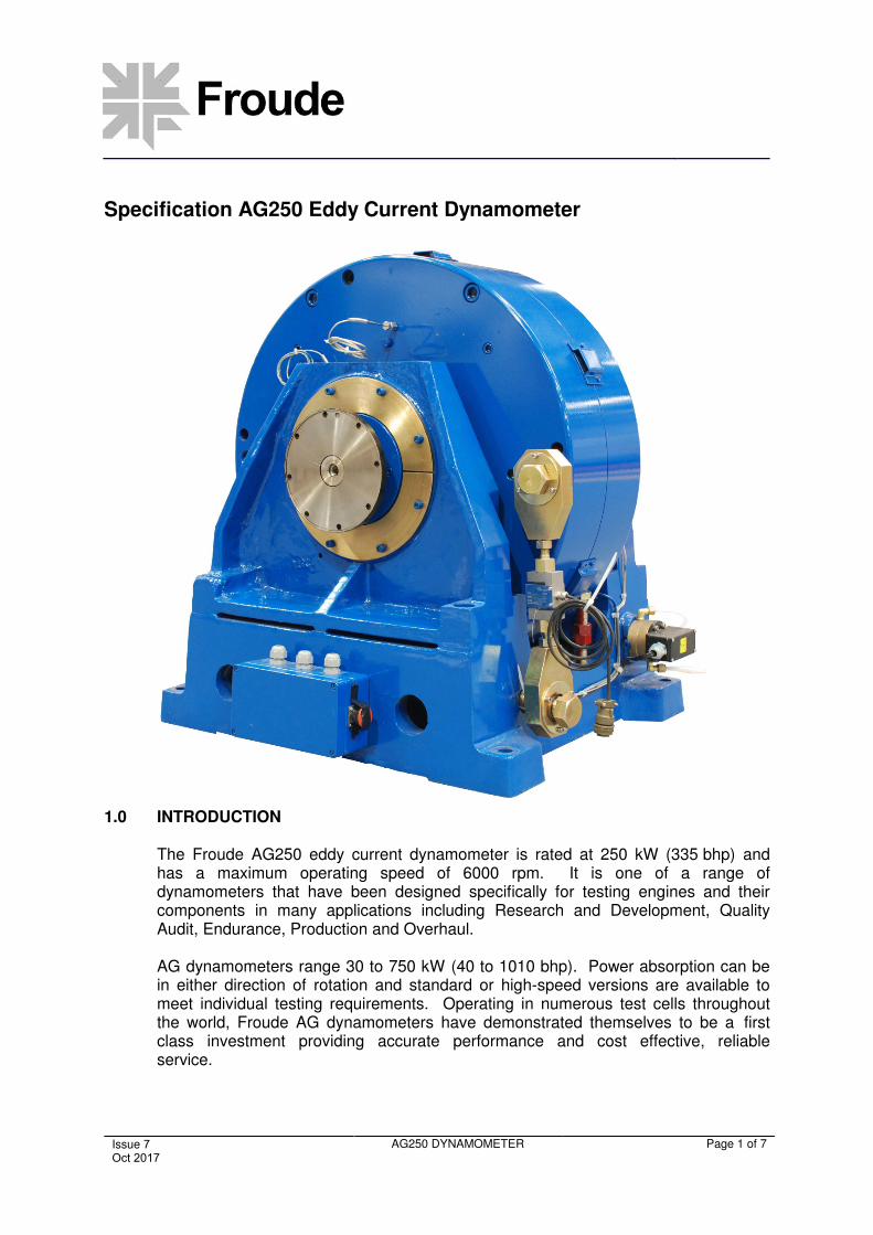
The Froude AG250 eddy current dynamometer is rated at 250 kW (335 bhp) and has a maximum operating speed of 6000 rpm. It is one of a range of dynamometers that have been designed specifically for testing engines and their components in many applications including Research and Development, Quality Audit, Endurance, Production and Overhaul.
AG dynamometers range 30 to 750 kW (40 to 1010 bhp). Power absorption can be in either direction of rotation and standard or high-speed versions are available to meet individual testing requirements. Operating in numerous test cells throughout the world, Froude AG dynamometers have demonstrated themselves to be a first class investment providing accurate performance and cost effective, reliable service.
Froude AG250
Issue 7 Oct 2017
AG250 DYNAMOMETER Page 2 of 7
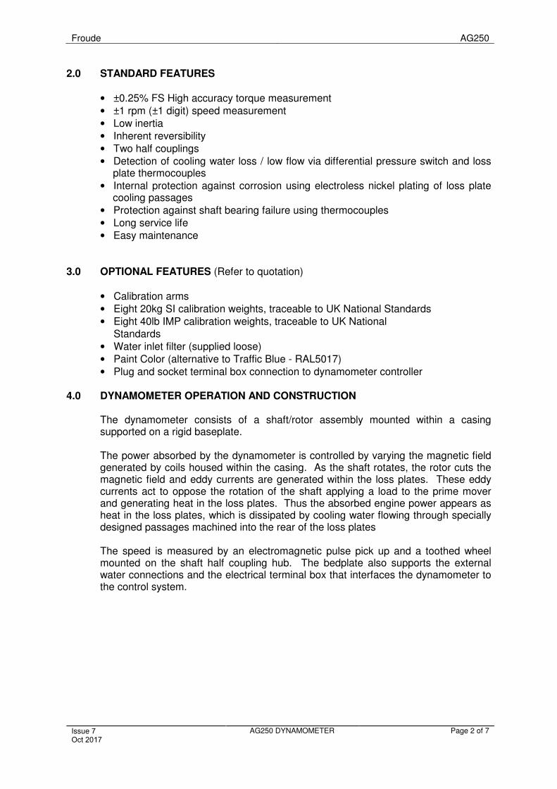
2.0 STANDARD FEATURES
• ±0.25% FS High accuracy torque measurement
• ±1 rpm (±1 digit) speed measurement
• Low inertia
• Inherent reversibility
• Two half couplings
• Detection of cooling water loss / low flow via differential pressure switch and lossplate thermocouples
• Internal protection against corrosion using electroless nickel plating of loss platecooling passages
• Protection against shaft bearing failure using thermocouples
• Long service life
• Easy maintenance
3.0 OPTIONAL FEATURES (Refer to quotation)
• Calibration arms
• Eight 20kg SI calibration weights, traceable to UK National Standards
• Eight 40lb IMP calibration weights, traceable to UK National Standards
• Water inlet filter (supplied loose)
• Paint Color (alternative to Traffic Blue - RAL5017)
• Plug and socket terminal box connection to dynamometer controller
4.0 DYNAMOMETER OPERATION AND CONSTRUCTION
The dynamometer consists of a shaft/rotor assembly mounted within a casing supported on a rigid baseplate.
The power absorbed by the dynamometer is controlled by varying the magnetic field generated by coils housed within the casing. As the shaft rotates, the rotor cuts the magnetic field and eddy currents are generated within the loss plates. These eddy currents act to oppose the rotation of the shaft applying a load to the prime mover and generating heat in the loss plates. Thus the absorbed engine power appears as heat in the loss plates, which is dissipated by cooling water flowing through specially designed passages machined into the rear of the loss plates
The speed is measured by an electromagnetic pulse pick up and a toothed wheel mounted on the shaft half coupling hub. The bedplate also supports the external water connections and the electrical terminal box that interfaces the dynamometer to the control system.
Froude AG250
Issue 7 Oct 2017
AG250 DYNAMOMETER Page 3 of 7
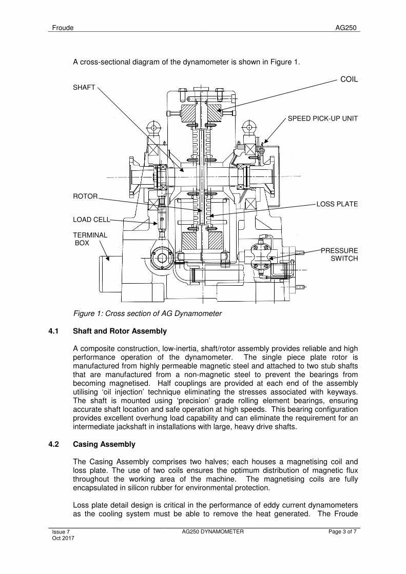
A cross-sectional diagram of the dynamometer is shown in Figure 1.
COIL SHAFT
SPEED PICK-UP UNIT
ROTOR LOSS PLATE
LOAD CELL
TERMINAL BOX
PRESSURE SWITCH
Figure 1: Cross section of AG Dynamometer
4.1 Shaft and Rotor Assembly
A composite construction, low-inertia, shaft/rotor assembly provides reliable and high performance operation of the dynamometer. The single piece plate rotor is manufactured from highly permeable magnetic steel and attached to two stub shafts that are manufactured from a non-magnetic steel to prevent the bearings from becoming magnetised. Half couplings are provided at each end of the assembly utilising ‘oil injection’ technique eliminating the stresses associated with keyways. The shaft is mounted using ‘precision’ grade rolling element bearings, ensuring accurate shaft location and safe operation at high speeds. This bearing configuration provides excellent overhung load capability and can eliminate the requirement for an intermediate jackshaft in installations with large, heavy drive shafts.
4.2 Casing Assembly
The Casing Assembly comprises two halves; each houses a magnetising coil and loss plate. The use of two coils ensures the optimum distribution of magnetic flux throughout the working area of the machine. The magnetising coils are fully encapsulated in silicon rubber for environmental protection.
Loss plate detail design is critical in the performance of eddy current dynamometers as the cooling system must be able to remove the heat generated. The Froude
Froude AG250
Issue 7 Oct 2017
AG250 DYNAMOMETER Page 4 of 7
4.3
design allows for controlled radial expansion of the loss plates and the parallel labyrinth of water-cooling passages has been optimised to ensure even cooling. The surfaces of these passages are electroless nickel plated to protect them from water corrosion. Additional cooling is also obtained by the free flow of air from the centre of the machine (through slots around the inner bearing housing) to the rotor/stator air gap and out of the radial ventilation slots on the periphery of the casing.
Thermocouples attached to each loss plate allow temperature measurements to be recorded for predictive maintenance and/or alarming if required.
Large deep groove ball bearings are used to support the casing; these provide the most precise method of mounting and are sized to reduce the possibility of brunelling.
Bedplate Assembly
The bedplate trunnion brackets support the outer race of the trunnion bearings allowing support with a minimum of friction, this method is extremely rigid and free from the resonance problems that can occur in the flexible type of mounting systems.
The torque is measured using a high precision strain guage load cell that is connected between the casing and the bedplate via self aligning bearings. It provides a measurement in both directions of rotation and can be accurately calibrated by adding weights to the calibration arms attached to the dynamometer casing. The calibration arms and weights are offered as options with the dynamometer.
The speed is measured by a pulse pick up sensor mounted on the casing and this detects a 60-tooth wheel located on the coupling hub.
All electrical signals are routed to a terminal box mounted in the bedplate and this provides the interface to dynamometer control system.
The external water connection flanges to the dynamometer are mounted on the bedplate. These are connected to the loss plates within the casing assembly by a transfer tube that permits movement of the casing. This design minimises the effects of varying supply pressure on torque measurement accuracy. A differential pressure switch connected to an orifice plate mounted in the water outlet flange of the machine is included as standard, this provides an alarm contact connection to the control system to protect the dynamometer from operation with an insufficient cooling water supply.
A filter in the water feed pipe is recommended to protect the dynamometer from
water borne debris. A 400µm filter is offered as an option with the dynamometer.
Froude AG250
Issue 7 Oct 2017
AG250 DYNAMOMETER Page 5 of 7
4.4
5.0
Control System
Froude can offer a choice of high quality control systems from the Texcel family to suit the any test application. All models provide constant speed, constant torque, power law and constant coil current modes of control.
The systems use feedback signals from the dynamometer’s speed sensor, load cell and coil current to provide safe operation & accurate control that has been
the trademark of Froude dynamometers since their invention in 1877. Seeseparate Texcel specification for details.
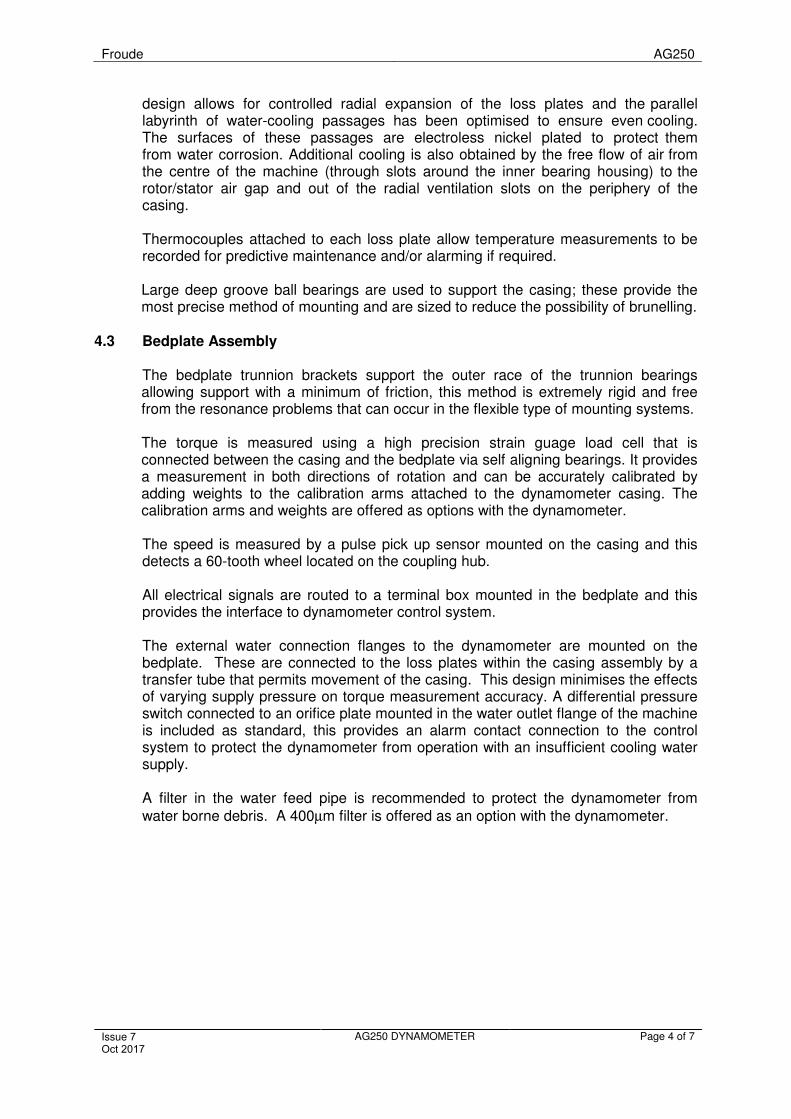
PHYSICAL DIMENSIONS OF AG250
`
A
D
K
E1 E
G G
B
J J
HH
C
F F
4 OFF FIXING
HOLES O I
DIMENSIONS in mm (Note: 25.4mm = 1 inch) FIXING WATER
A B C D E E1 F G H I J K 835 705 740 465 275 275 1,066 285 340 22 192 97
Water Connections : 40mm nominal bore, with 4x M16 studs on a 110mm PCD.
Half Coupling Size : SAE1710, having a flange diameter of 203mm by 14mm thick, 8 fixing holes of 10.2mm diameter on a 184.2mm PCD and a female location spigot diameter of 196.8mm by 1.3mm deep.
Froude AG250
Issue 7 Oct 2017
AG250 DYNAMOMETER Page 6 of 7
5.1 Technical Data
General Arrangement Drawing : BA2500020 Weight (approximately) : 1180 kg (2605 lbs) Inertia : 0.464 kg.m
2 (11.02 lbf.ft
2)
Torsional Stiffness (half shaft) : 0.58 MNm/rad Colour : Traffic Blue - RAL5017
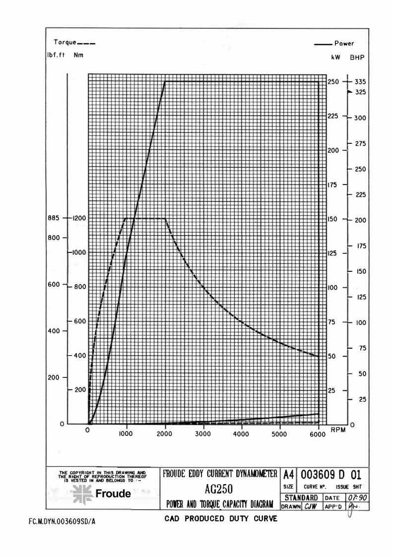
Duty
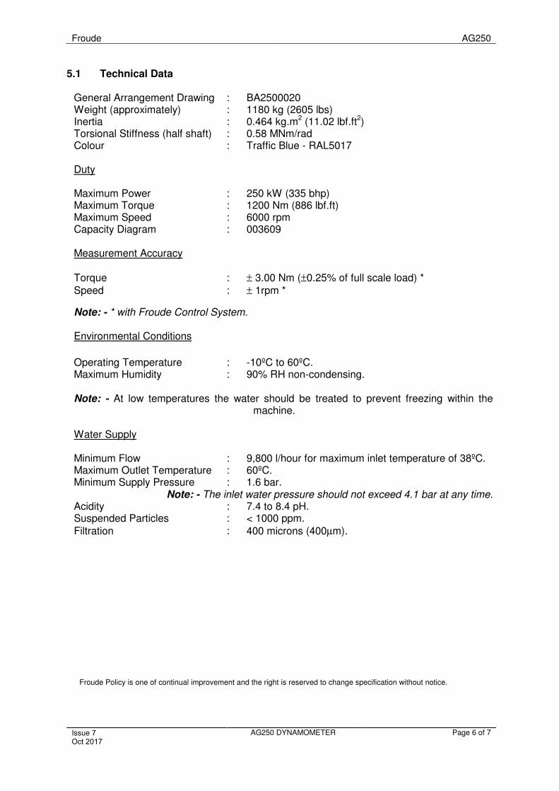
Maximum Power : 250 kW (335 bhp) Maximum Torque : 1200 Nm (886 lbf.ft) Maximum Speed : 6000 rpm Capacity Diagram : 003609
Measurement Accuracy
Torque : ± 3.00 Nm (±0.25% of full scale load) *
Speed : ± 1rpm *
Note: - * with Froude Control System.
Environmental Conditions
Operating Temperature : -10ºC to 60ºC.Maximum Humidity : 90% RH non-condensing.
Note: - At low temperatures the water should be treated to prevent freezing within the machine.
Water Supply
Minimum Flow : 9,800 l/hour for maximum inlet temperature of 38ºC. Maximum Outlet Temperature : 60ºC. Minimum Supply Pressure : 1.6 bar.
Note: - The inlet water pressure should not exceed 4.1 bar at any time. Acidity : 7.4 to 8.4 pH. Suspended Particles : < 1000 ppm.
Filtration : 400 microns (400µm).
Froude Policy is one of continual improvement and the right is reserved to change specification without notice.
-
Torque ___ -Power
lbf. ft Nm kW BHP
250 --335
.- 325
225 --300
.- 275 200 -
- 250
175 -
- 225
885 --1200 150 -- 200
800 -
- 175 -1000 125 -
- 150
600--800 100 -
- 125
-600 75 -- 100
400 -
- 75
-400 50 -
200 -- 50
-200 25 -
- 25 I
0 0 0
1000 2000 3000 4000 5000 6000 RPM
TltE COPYRIGHT IN THIS DRAWING ANO TltE RIGHT Of' REP-ROOUCTION THEREOF
IS VESTED IN AN> l!fLONGS TO , -
FROUDE EDDY CURREMT DYNAWtEIER A4 003609 D 01
AG250 SIZE CURVE N•. ISSUE SHT
POWER AND 'IOIQJE_ CAPACITt' DIAGRAM STAiNDARD DATE I 07:90
DRAWN CJW APP'O I pf>.,.
FC.M.DYN.003609S0/A CAD PRODUCED DUlY CURVE