Embed Size (px)
Citation preview

This document is subject to Anders Electronics plc’s standard terms and conditions of sale. Prior to concluding any agreement with Anders Electronics plc, the customer should satisfy itself of the accuracy and completeness of the information contained herein and should notify Anders of any intended use of the product. anders electronics plc | Kings Studios, 43-45 Kings Terrace, London, NW1 0JR | Tel: +44(0)20 7388 7171| Fax: +44(0)20 7383 2423 | www.andersDX.com | [email protected]
Specification for Colour TFT Display module 1.54" Colour TFT Display module
Manufacturer Yes Optoelectronics Co., Ltd
Part n˚ YTS154LAA-01-100N Ordering n˚ YTS154LAA-01-100N
Customer Part n˚ n/a
Revision n˚ 1.0 Issue Date 2017/05/15
Customer’s Approval
Company name Printed name
Job title Signature
Approval Stage:
This product is approved for the following production stage: -
Sample / Prototype
Pre-Production
Mass Production Approval Date
Supplied by Anders Electronics plc
Manufactured by Yes Optoelectronics Co., Ltd

LCD MODULE YTS154LAA-01-100N Version : 1.0 MAY.15.2017
1 of 25
PRODUCT : LCD MODULE
MODEL NO : YTS154LAA-01-100N
SUPPLIER : Yes Optoelectronics Co.,Ltd
DATE : MAY.15.2017
SPECIFICATION
Approved Checked Department
XIAO YU
LIANGYUEYAO
TP & TFT LCM Department
CUSTOMER: MODEL NO.: DATE:
Approved Checked Department
ADD: No.288Yueling Road Anshan,Liaoning,CHINA TEL: 86-412-5211859 FAX: 86-412-5211729 P.C.:114045 E-mail : [email protected], [email protected] Web: http://www.yes-lcd.com
http://www.asiansources.com/sante.com

LCD MODULE YTS154LAA-01-100N Version : 1.0 MAY.15.2017
2 of 25
CONTENTS
1.General Specifications .............................................................................................................. 4
2.Mechanical Drawing ................................................................................................................. 5
3.PIN Assignment ........................................................................................................................ 6
4.Absolute Maximum Rating ....................................................................................................... 7
5.Electrical Characteristics ........................................................................................................... 7
5.1.Recommended Operating Condition.................................................................................. 7
5.2.Rcommended Driving Condition for Backlight ................................................................ 7
6. Timing Characteristics ............................................................................................................. 8
6.1.AC Electrical Characteristics ............................................................................................. 8
6.2. DC Electrical Characteristics ............................................................................................ 9
6.3. Timing ............................................................................................................................. 10
6.4.Power ON/OFF Sequence ................................................................................................ 11
7.Optical Characteristics ............................................................................................................ 12
8.Environmental/Reliability Test ............................................................................................... 15
9.Packing Drawing ..................................................................................................................... 16
10. Standard Specifications For Product Quality ....................................................................... 19
11.Precautions for Use of LCD Modules ................................................................................... 21
12.Prior Consult Matter .............................................................................................................. 25
13.Factory ................................................................................................................................... 25

LCD MODULE YTS154LAA-01-100N Version : 1.0 MAY.15.2017
3 of 25
Revision Record
Rev No.
Rev Date
Contents
Remarks
1.0 MAY.15.2017 New creation

LCD MODULE YTS154LAA-01-100N Version : 1.0 MAY.15.2017
4 of 25
1. General Specifications
No Item Contents Unit
1 Size 1.54 inch
2 Resolution 240RGB*240
3 Interface SPI/RGB
4 Color Depth 262k
5 Pixel Pitch 0.0867*0.0867 mm
6 Pixel Arrangement RGB Vertical Stripe
7 Display Mode Transmissive
8 Viewing Direction free o’clock
9 LCM (W x H x D) 31.52*33.72*1.54 mm
10 Active Area (W x H) 27.72*27.72 mm
11 With/Without TSP Without TSP
12 LED Numbers 3
LCD MODULE YTS154LAA-01-100N Version : 1.0 MAY.15.2017
5 of 25
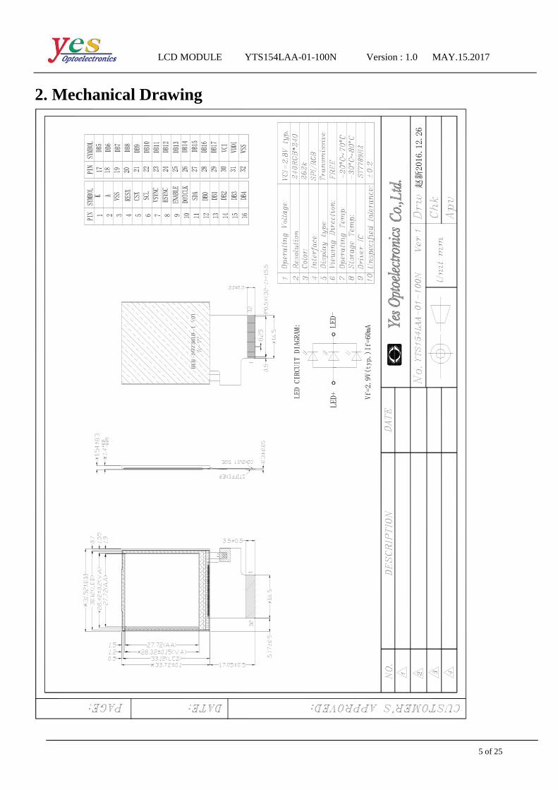
2. Mechanical Drawing
Vf=2.9V(typ.)If=60mA
LED CIRCUIT DIAGRAM:
KA
赵新
2016.12.26

LCD MODULE YTS154LAA-01-100N Version : 1.0 MAY.15.2017
6 of 25
3. PIN Assignment
Ps. For further details, please refer to ST7789H2 data sheet.
Pin No Symbol I/O Function Remark
1 K P LED backlight cathode
2 A P LED backlight anode
3 VSS P Ground
4 RESX I This signal will reset the device and it must be applied to
properly initialize the chip.
5 CSX I Chip selection pin. Low-active.
6 SCL I Write enable in MCU parallel interface.
7 HSYNC I -Horizontal synchronizing input signal for RGB interface
operation.
8 VSYNC I -Vertical synchronizing input signal for RGB interface
operation.
9 ENABLE I Data enable signal for RGB interface operation.
10 DOTCLK I
Clock signal for data latching and internal counter of
11 SDA I/O SPI interface input/output pin.
12-29 DB0-DB17 I/O
DB[17:0] are used as RGB interface data bus.
6-bit RGB I/F: DB[5:0] are used.
16-bit RGB I/F: DB[17:13], DB[11:1] are used.
18-bit RGB I/F: DB[17:0] are used.
30 VCI P Power supply for analog and booster circuits.
31 VDDI P Power supply for I/O system
32 VSS P Ground
LCD MODULE YTS154LAA-01-100N Version : 1.0 MAY.15.2017
7 of 25
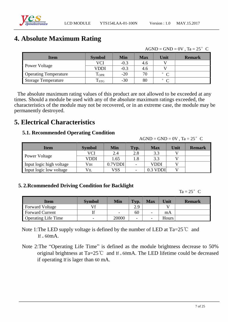
4. Absolute Maximum Rating
AGND = GND = 0V , Ta = 25°C
The absolute maximum rating values of this product are not allowed to be exceeded at any times. Should a module be used with any of the absolute maximum ratings exceeded, the characteristics of the module may not be recovered, or in an extreme case, the module may be permanently destroyed.
5. Electrical Characteristics
5.1. Recommended Operating Condition AGND = GND = 0V , Ta = 25°C
5. 2.Rcommended Driving Condition for Backlight
Ta = 25°C
Note 1:The LED supply voltage is defined by the number of LED at Ta=25 and
If = 60mA.
Note 2:The “Operating Life Time” is defined as the module brightness decrease to 50%
original brightness at Ta=25 and If = 60mA. The LED lifetime could be decreased
if operating If is lager than 60 mA.
Item Symbol Min Max Unit Remark
Power Voltage VCI -0.3 4.6 V
VDDI -0.3 4.6 V
Operating Temperature TOPR -20 70 °C
Storage Temperature TSTG -30 80 °C
Item Symbol Min Typ. Max Unit Remark
Power Voltage VCI 2.4 2.8 3.3 V
VDDI 1.65 1.8 3.3 V
Input logic high voltage VIH 0.7VDDI - VDDI V
Input logic low voltage VIL VSS - 0.3 VDDI V
Item Symbol Min Typ. Max Unit Remark
Forward Voltage Vf 2.9 V
Forward Current If - 60 - mA
Operating Life Time - 20000 - - Hours

LCD MODULE YTS154LAA-01-100N Version : 1.0 MAY.15.2017
8 of 25
6. Timing Characteristics
6.1. AC Electrical Characteristics

LCD MODULE YTS154LAA-01-100N Version : 1.0 MAY.15.2017
9 of 25
6. 2.DC Electrical Characteristics

LCD MODULE YTS154LAA-01-100N Version : 1.0 MAY.15.2017
10 of 25
6. 3.Timing

LCD MODULE YTS154LAA-01-100N Version : 1.0 MAY.15.2017
11 of 25
6. 4.Power ON/OFF Sequence

LCD MODULE YTS154LAA-01-100N Version : 1.0 MAY.15.2017
12 of 25
7. Optical Characteristics
Test Conditions:
1. If= 60 mA(Backlight current), VCI =2.8V,the ambient temperature is 25°C.
2. The test systems refer to Note 2.
Item Symbol Condition Min Typ Max Unit Remark
View Angles
θT
CR≥10
75 80
Degree Note 2 θB 75 80
θL 75 80
θR 75 80
Contrast Ratio CR θ = 0° 700 900 - Note 1
Note 3
Response Time TON
25°C - 35 50 ms Note 1
Note 4 TOFF
Chromaticity Wx x 0.283 0.298 0.313 Note 1
Note 5 Wy y 0.313 0.328 0.343
Uniformity U 80 - % Note 5
Luminance L 390 420 - cd/m2 Note 1
Note 5

LCD MODULE YTS154LAA-01-100N Version : 1.0 MAY.15.2017
13 of 25
Note1: Definition of optical measurement system.
The optical characteristics should be measured in dark room. After 5Minutes operation, the
optical properties are measured at the center point of the LCD screen. ALL input terminals
LCD panel must be ground when measuring the center area of the panel.
Note2: Definition of viewing angle range and measurement system.
Viewing angle is measured at the center point of the LCD by CONOSCOPE (DMS703)
NOTE3: Definition of contrast ratio
Item Photo detector Field
Contrast Ratio
CS1000
1º Luminance
Lum Uniformity
Chromaticity CS1000
Response Time DMS703
-

LCD MODULE YTS154LAA-01-100N Version : 1.0 MAY.15.2017
14 of 25
“White state ”:The state is that the LCD should drive by Vwhite.
“Black state ”:The state is that the LCD should drive by Vblack.
Vwhite: To be determined Vblack: To be determined
Note4:Definition of Response time
The response time is defined as the LCD optical switching time interval between “White”state
and “Black” state. Rise time (TON)is the time between photo detector output intensity changed
from 90% to 10%.And fall time (TOFF)is the time between photo detector output intensity
changed from 10% to90%.
Note5:Definition of color chromaticity(CIE1931)
Color coordinates measured at center point of LCD.
Note6: Definition of Luminance Uniformity
Active area is divided into 9 measuring areas(Refer Fig.2).Every measuring point is placed at
the center of each measuring area.
Luminance Uniformity (U)=Lmin/Lmax
L--------Active area length W--------Active area width
L max: The measured Maximum luminance of all measurement position.
L min: The measured Minimum luminance of all measurement position.
Note7: Definition of luminance:
Measure the luminance of white state at center point.
LCD MODULE YTS154LAA-01-100N Version : 1.0 MAY.15.2017
15 of 25
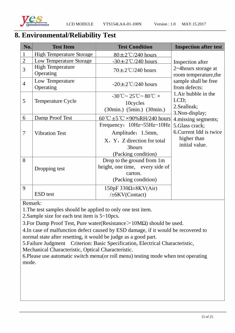
8. Environmental/Reliability Test
No. Test Item Test Condition Inspection after test
1 High Temperature Storage 80±2/240 hours Inspection after
2~4hours storage at
room temperature,the
sample shall be free
from defects:
1.Air bubble in the
LCD;
2.Sealleak;
3.Non-display;
4.missing segments;
5.Glass crack;
6.Current Idd is twice
higher than
initial value.
2 Low Temperature Storage -30±2/240 hours 3
High Temperature
Operating
70±2/240 hours
4
Low Temperature
Operating
-20±2/240 hours
5
Temperature Cycle
-30~ 25~ 80 ×
10cycles
(30min.) (5min.) (30min.)
6 Damp Proof Test 60±5×90%RH/240 hours 7
Vibration Test
Frequency:10Hz~55Hz~10Hz
Amplitude:1.5mm,
X,Y,Z direction for total
3hours
(Packing condition)
8 Dropping test
Drop to the ground from 1m
height, one time, every side of
carton.
(Packing condition)
9 ESD test
150pF 330Ω±8KV(Air)
/±6KV(Contact)
Remark:
1.The test samples should be applied to only one test item.
2.Sample size for each test item is 5~10pcs.
3.For Damp Proof Test, Pure water(Resistance>10MΩ) should be used.
4.In case of malfunction defect caused by ESD damage, if it would be recovered to
normal state after resetting, it would be judge as a good part.
5.Failure Judgment Criterion: Basic Specification, Electrical Characteristic,
Mechanical Characteristic, Optical Characteristic.
6.Please use automatic switch menu(or roll menu) testing mode when test operating
mode.

LCD MODULE YTS154LAA-01-100N Version : 1.0 MAY.15.2017
16 of 25
9. Packing Drawing
TBD

LCD MODULE YTS154LAA-01-100N Version : 1.0 MAY.15.2017
17 of 25
10. Standard Specifications For Product Quality 10.1. Manner of test:
10.1.1 The test must be under 40W fluorescent light, and the distance of view must be at
30±10cm.
10.1.2 Room temperature 25±5 Humidity: (60±10)%RH.
10.2. Quality specification
It shall be based on GB2828-87, inspection level II .
IETM CHECK LEVEL AQL
MAJOR
(MA)
1.Liquid crystal leakage
2.Wrong polarizer
3.Outside dimension
4. Bright dot、Dark dot
5. Display abnormal
6. Class crack
Ⅱ 0.25
MINOR
(MI)
1. Spot Defect (Including black spot、white spot、
pinhole、foreign particle、bubbles、hurt)
2. fragment
3. Line Defect (Including black line、white line、scratch)
4. Incision defect
5. Newton’s ring
6. Other visual defects
Ⅱ 1.0
10.3. Definition of area: Ⅰ
10.3.1 Ⅰ area: viewing area Ⅱ
Ⅱ area: outside viewing area
10.4.Standard of appearance test for Ⅰ area: (unit: mm)
NOTE:Defect ignore for Ⅱ area .

LCD MODULE YTS154LAA-01-100N Version : 1.0 MAY.15.2017
18 of 25
10.4.1 Bright/Dark Dots explain
Name Explain Definition
Bright dot
Dots appear bright and unchanged in size in which LCD panel
isdisplaying under black pattern
The definition of dot:
The size of a defective
dot over 1/2 of single
pixel dot is regarded
as one defective dot .
NOTE: One pixel
consists of 3 sub-pixels,
including R,G, and B
dot.(Sub-pixel = Dot)
Dark dot
Dots appear dark and unchanged in size in which LCD panel
isdisplaying under pure red, green, blue pattern.
ADJACE
NT DOT Adjacent two sub-pixel are defect(define two dot defect)
10.4.2 Inspection standard
Items Criterion Checking Manner
Defect
Classes
1 Bright/dark dot
Under 6”
(contain 6”)
Bright dot:2
Dark dot:N≤4
Note: be more than 5mm apart
Checking
with eyes MAJ
6”-12”
Bright dot:N≤4
Dark dot:N≤5
Total Bright and Dark Dots:N≤8
Note :
1.Two bright dot defects (red, green,
blue, and white) should be larger
than 15mm;
2.The distance between black dot
defects or black and bright dot
defects should be more than 5mm
apart.
2
Spot Defect
(Including black
spot.white spot.
Pinhole.foreign
particle.bubbles.h
urt)
D=(X+Y)/2
Under 6”
(contain 6”)
D≤0.1 Ignore
0.1<D≤0.35 N≤3
0.35<D N=0
Checking
with eyes MIN
6”-12”
D≤0.3 Ignore
0.3<D≤0.6 N≤4
0.6<D N=0
LCD MODULE YTS154LAA-01-100N Version : 1.0 MAY.15.2017
19 of 25
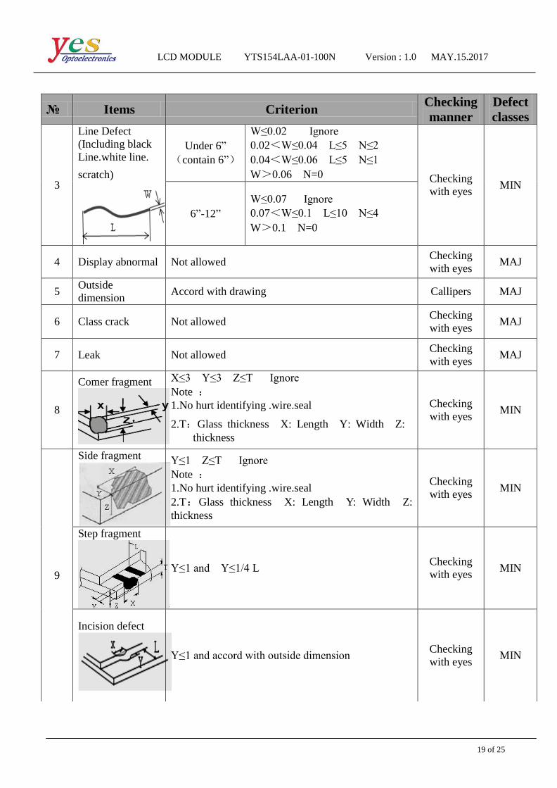
Items Criterion Checking
manner
Defect
classes
3
Line Defect
(Including black
Line.white line.
scratch)
Under 6”
(contain 6”)
W≤0.02 Ignore
0.02<W≤0.04 L≤5 N≤2
0.04<W≤0.06 L≤5 N≤1
W>0.06 N=0 Checking
with eyes MIN
6”-12”
W≤0.07 Ignore
0.07<W≤0.1 L≤10 N≤4
W>0.1 N=0
4 Display abnormal Not allowed Checking
with eyes MAJ
5 Outside
dimension Accord with drawing Callipers MAJ
6 Class crack Not allowed Checking
with eyes MAJ
7 Leak Not allowed Checking
with eyes MAJ
8
Comer fragment
X≤3 Y≤3 Z≤T Ignore
Note :
1.No hurt identifying .wire.seal
2.T:Glass thickness X: Length Y: Width Z:
thickness
Checking
with eyes MIN
9
Side fragment
Y≤1 Z≤T Ignore
Note :
1.No hurt identifying .wire.seal
2.T:Glass thickness X: Length Y: Width Z:
thickness
Checking
with eyes MIN
Step fragment
Y≤1 and Y≤1/4 L Checking
with eyes MIN
Incision defect
Y≤1 and accord with outside dimension Checking
with eyes MIN

LCD MODULE YTS154LAA-01-100N Version : 1.0 MAY.15.2017
20 of 25
Items Criterion Checking
manner
Defect
classes
10
Newton’s ring
(CTP or Cover
board)
D=(X+Y)/2
Under 6”
(contain 6”)
6”-12”
D≤25 N≤3
D>25 N=0
D≤70 N≤5
D>70 N=0
Checking
with eyes MIN
LCD MODULE YTS154LAA-01-100N Version : 1.0 MAY.15.2017
21 of 25
11. Precautions for Use of LCD Modules 11.1 Handing Precautions
(1) The display panel is made of glass and polarizer. As glass is fragile. It tends to become or chipped during handling especially on the edges. Please avoid dropping or jarring. Do not subject it to a mechanical shock by dropping it or impact.
(2) If the display panel is damaged and the liquid crystal substance leaks out, be sure not to get any in your mouth. If the substance contacts your skin or clothes, wash it off using soap and water.
(3) Do not apply excessive force to the display surface or the adjoining areas since this may cause the color tone to vary. Do not touch the display with bare hands. This will stain the display area and degraded insulation between terminals (some cosmetics are determined to the polarizer).
(4) The polarizer covering the display surface of the LCD module is soft and easily scratched. Handle this polarizer carefully. Do not touch, push or rub the exposed polarizers with anything harder than an HB pencil lead (glass,tweezers, etc.). Do not put or attach anything on the display area to avoid leaving marks on. Condensation on the surface and contact with terminals due to cold will damage, stain or dirty the polarizer. After products are tested at low temperature they must be warmed up in a container before coming is contacting with room temperature air.
(5) If the display surface becomes contaminated, breathe on the surface and gently wipe it with a soft dry cloth. If it is heavily contaminated, moisten cloth with one of the following solvents
- Isopropyl alcohol - Ethyl alcohol
Do not scrub hard to avoid damaging the display surface.
(6) Solvents other than those above-mentioned may damage the polarizer. Especially, do
not use the following.
- Water
- Ketone
- Aromatic solvents
Wipe off saliva or water drops immediately, contact with water over a long period of time
may cause deformation or color fading. Avoid contacting oil and fats.
(7) Exercise care to minimize corrosion of the electrode. Corrosion of the electrodes is
accelerated by water droplets, moisture condensation or a current flow in a high-humidity
environment.
(8) Install the LCD Module by using the mounting holes. When mounting the LCD
module make sure it is free of twisting, warping and distortion. In particular, do not forcibly
pull or bend the cable or the backlight cable.
(9) Do not attempt to disassemble or process the LCD module.
(10) NC terminal should be open. Do not connect anything.
(11) If the logic circuit power is off, do not apply the input signals.
(12) Electro-Static Discharge Control,Since this module uses a CMOS LSI, the same
careful attention should be paid to electrostatic discharge as for an ordinary CMOS IC. To
prevent destruction of the elements by static electricity, be careful to maintain an optimum
work environment.
LCD MODULE YTS154LAA-01-100N Version : 1.0 MAY.15.2017
22 of 25
- Before remove LCM from its packing case or incorporating it into a set, be sure the module and your body have the same electric potential.Be sure to ground the body when handling the LCD modules.
- Tools required for assembling, such as soldering irons, must be properly grounded. make certain the AC power source for the soldering iron does not leak. When using an electric screwdriver to attach LCM, the screwdriver should be of ground potentiality to minimize as much as possible any transmission of electromagnetic waves produced sparks coming from the commutator of the motor.
- To reduce the amount of static electricity generated, do not conduct assembling and other work under dry conditions. To reduce the generation of static electricity be careful that the air in the work is not too dried. A relative humidity of 50%-60% is recommended.As far as possible make the electric potential of your work clothes and that of the work bench the ground potential.
The LCD module is coated with a film to protect the display surface. Exercise care when
peeling off this protective film since static electricity may be generated.
(13)Since LCM has been assembled and adjusted with a high degree of precision, avoid
applying excessive shocks to the module or making any alterations or modifications to it.
- Do not alter, modify or change the shape of the tab on the metal frame.
- Do not make extra holes on the printed circuit board, modify its shape or change the
positions of components to be attached.
- Do not damage or modify the pattern writing on the printed circuit board.
- Absolutely do not modify the zebra rubber strip (conductive rubber) or heat seal
connector.
- Except for soldering the interface, do not make any alterations or modifications with
a soldering iron.
- Do not drop, bend or twist LCM. 11.2 Storage Precautions
When storing the LCD modules, the following precaution is necessary. (1) Store them in a sealed polyethylene bag. If properly sealed, there is no need for the
dessicant.
(2) Store them in a dark place. Do not expose to sunlight or fluorescent light, keep the
temperature between 0C and 35C. (3) The polarizer surface should not come in contact with any other objects. (We advise you to store them in the container in which they were shipped).
11.3 Others
Liquid crystals solidify under low temperature (below the storage temperature range) leading to defective orientation or the generation of air bubbles (black or white). Air bubbles may also be generated if the module is subject to a low temperature.
If the LCD modules have been operating for a long time showing the same display patterns, the display patterns may remain on the screen as ghost images and a slight contrast irregularity may also appear.A normal operating status can be regained by suspending use for some time. It should be noted that this phenomenon does not adversely affect performance reliability.
To minimize the performance degradation of the LCD modules resulting from destruction caused by static electricity etc., exercise care to avoid holding the following

LCD MODULE YTS154LAA-01-100N Version : 1.0 MAY.15.2017
23 of 25
sections when handling the modules. - Exposed area of the printed circuit board. -Terminal electrode sections.
11.4 USING LCD MODULES
Installing LCD Modules The hole in the printed circuit board is used to fix LCM as shown in the picture below.
Attend to the following items when installing the LCM. (1) Cover the surface with a transparent protective plate to protect the polarizer and LC cell.
(2) When assembling the LCM into other equipment, the spacer to the bit between the LCM and the fitting plate should have enough height to avoid causing stress to the module surface, refer to the individual specifications for measurements. The measurement tolerance should be 0.1mm.
Precaution for assemble the module with BTB connector: Please note the position of the male and female connector position,don’t assemble or
assemble like the method which the following picture shows
Precaution for soldering to the LCM
Hand soldering Machine drag
soldering
Machine press soldering No ROHS
Product
290C~350C. Time : 3-5S.
330C ~350C. Speed : 4-8mm/s.
300C~330C. Time : 3-6S. Press: 0.8~1.2Mpa
ROHS
Product
340C~370C. Time : 3-5S.
350C ~370C. Time : 4-8 mm/s.
330C~360C. Time : 3-6S. Press: 0.8~1.2Mpa
(1)If soldering flux is used, be sure to remove any remaining flux after finishing to

LCD MODULE YTS154LAA-01-100N Version : 1.0 MAY.15.2017
24 of 25
soldering operation. (This does not apply in the case of a non-halogen type of flux.) It is recommended that you protect the LCD surface with a cover during soldering to prevent any damage due to flux spatters.
(2) When soldering the electroluminescent panel and PC board, the panel and board should not be detached more than three times. This maximum number is determined by the temperature and time conditions mentioned above, though there may be some variance depending on the temperature of the soldering iron.
(3) When remove the electroluminescent panel from the PC board, be sure the solder has completely melted, the soldered pad on the PC board could be damaged.
Precautions for Operation (1) It is an indispensable condition to drive LCD's within the specified voltage limit
since the higher voltage then the limit cause the shorter LCD life.An electrochemical
reaction due to direct current causes LCD's undesirable deterioration, so that the use of
direct current drive should be avoided.
(2) Response time will be extremely delayed at lower temperature than the operating
temperature range and on the other hand at higher temperature LCD's show dark color in
them.However those phenomena do not mean malfunction or out of order with LCD's,
Which will come back in the specified operating temperature.
(3) If the display area is pushed hard during operation, the display will become abnormal.
However, it will return to normal if it is turned off and then back on.
(4) A slight dew depositing on terminals is a cause for electro-chemical reaction resulting
in terminal open circuit. Usage under the maximum operating temperature,50%RH or less is
required.
(5) Input each signal after the positive/negative voltage becomes stable.
(6) Please keep the temperature within specified range for use and storage. Polarization
degradation, bubble generation or polarizer peel-off may occur with high temperature and high
humidity.
Safety (1) It is recommended to crush damaged or unnecessary LCDs into pieces and wash
them off with solvents such as acetone and ethanol, which should later be burned. (2) If any liquid leaks out of a damaged glass cell and comes in contact with the
hands, wash off thoroughly with soap and water. 11.5The disposal of waste
For waste disposal, our recommendations are as follows, please refer to your company
and the relevant provisions of the state laws and regulations of the act accordingly
1. Packing materials disposal for our packaging (carton/PS tray/EPE tray/PET tray)
1)Our company used to recycle and reuse materials, packing materials can be you just
need to transfer to material recycling companies
2. Our scrap module can't be recycled for reuse, so please dispose of,
1) Our scrap module can't be recycled for reuse, products and components are
"served" can lead to accidents
2) Our scrap can be transfer to material recycling companies, dismantling, to ensure that

LCD MODULE YTS154LAA-01-100N Version : 1.0 MAY.15.2017
25 of 25
scrap in relatively advanced technology products, environmental protection measures of
relatively perfect environment for processing. 3. WEEE order must be executed in product scrap.
12. Prior Consult Matter 1.①For YES standard products, we keep the right to change material, process ... for
improving the product property without notice on our customer. ②For OEM products, if any change needed which may affect the product property, we
will consult with our customer in advance. 2.If you have special requirement about reliability condition, please let us know before you
start the test on our samples.
13. Factory
FACTORY NAME: ANSHAN YES OPTOELECTRONICS DISPLAY CO.,LTD
FACTORY ADDRESS: No.288Yueling Road Anshan, Liaoning, P.R.CHINA
FACTORY PHONE: 86-412-5211859 FAX: 86-412-5211729