Embed Size (px)
Citation preview
L-S3 (April 1999)
SPECIFICATION FOR LOW VOLTAGE UNDERGROUND CABLE©Hak Cipta : 1999 Cawangan Elektrik JKR Malaysia
i/i
SPECIFICATION FOR LOW VOLTAGE UNDERGROUND CABLE
ITEM CONTENTS PAGE
1.0 General 1
2.0 Types Of Cables 1
3.0 Cable Routes 2
4.0 Length Of Cable 3
5.0 Cable Trench 3
6.0 Cable Ducts 4
7.0 Traffic Safety And Control 5
8.0 Cable Laying And Installation 5
8.1 Cable Laid Direct In Ground 6
8.2 Cable Installed In Pre-Cast Concrete Trenches 7
8.3 Cable Run On Walls And Under Floor Slabs 8
9.0 Cable Termination And Jointing 8
9.1 Termination Of PVC Insulated ArmouredCables 9
9.2 Termination Of Paper Insulated Cables 9
9.3 Cable Jointing 10
10.0 Cable Markers 11
11.0 Testing And Commissioning 11
12.0 Maintenance 12
13.0 Shop Drawings And As Installed Drawings 13
13.1 Shop Drawings 13
13.2 As Installed Drawings 13
L-S3 (April 1999)
SPECIFICATION FOR LOW VOLTAGE UNDERGROUND CABLE©Hak Cipta : 1999 Cawangan Elektrik JKR Malaysia
ii/ii
Appendix: A - uPVC Cable Protective Cover I
Appendix: B! - Cable Marker -Directional Sign And Lettering II
Appendix: B2 - Cable Marker -Joint Sign And Lettering III
Appendix: B3 - Cable Marker - Construction IV
L-S3 (April 1999)
SPECIFICATION FOR LOW VOLTAGE UNDERGROUND CABLE©Hak Cipta : 1999 Cawangan Elektrik JKR Malaysia
1/14
SPECIFICATION FOR LOW VOLTAGE UNDERGROUND CABLE
1.0 GENERAL
This section of the Specification describes and specifies requirements forthe supply, delivery, installation, testing, commissioning, handing over inapproved working order and maintenance during the Defects LiabilityPeriod of the underground cabling work in accordance with thespecifications, Supplementary Notes, Bill of Quantities, Conditions ofContracts, Drawing and other related documents.
2.0 TYPES OF CABLES
This specification shall cover the following types of cables: -
(a) PVC/SWA/PVC CABLE - Cable shall be manufactured andtested in accordance with MS 274 or BS 6346 and shall have highconductivity plain copper stranded conductors insulated with PVCsuitable for a voltage of 600/1000 V laid together and bedded withPVC, armoured with galvanised steel wires and sheathed withPVC.
(b) XLPE/SWA/PVC CABLE - Cable shall be manufactured andtested in accordance to BS 5467 or IEC 60502 and shall have highconductivity plain copper stranded conductors, insulated withcross-linked polyethylene (XLPE), suitable for a voltage of600/1000 V laid together and bedded with extruded PVC,armoured with galvanised steel wires and sheathed with PVC.
(c) XLPE/AWA/PVC CABLE - Cable shall be manufactured andtested in accordance to BS 5467 or IEC 60502 and shall have highconductivity plain copper stranded conductors, insulated withcross-linked polyethylene (XLPE), suitable for a voltage of600/1000 V laid together and bedded with extruded PVC,armoured with aluminium wires and sheathed with PVC.
L-S3 (April 1999)
SPECIFICATION FOR LOW VOLTAGE UNDERGROUND CABLE©Hak Cipta : 1999 Cawangan Elektrik JKR Malaysia
2/14
(d) XLPE/PVC CABLE - Cable shall be manufactured and tested inaccordance to BS 5467 or IEC 60502 and shall have highconductivity plain copper stranded conductors, insulated withcross-linked polyethylene (XLPE), suitable for a voltage of600/1000 V laid together and bedded with extruded PVC andsheathed with PVC.
(e) PILCDSTAS CABLE - Cable shall be manufactured and tested inaccordance with BS 6480 Part 1 and shall have high conductivityplain copper stranded conductors, insulated with strong long fibrepaper, uniform in texture, free from metallic particles, massimpregnated with non-draining insulating oil compound suitable fora voltage of 600/1000 V, lead alloy sheathed, double steel typearmoured and served.
(f) PILCDS CABLE - Cable shall be manufactured and tested inaccordance with BS 6480 Part 1 and shall have high conductivityplain copper stranded conductors, insulated with strong long fibrepaper, uniform in texture, free from metallic particles, massimpregnated with non-draining insulating oil compound suitable fora voltage of 600/1000 V lead alloy sheathed and served.
3.0 CABLE ROUTES
Cable routes shown in the Drawings are for tendering purpose only. TheElectrical Contractor shall submit shop drawings as required in 13.1 of theproposed routes and peg out the cable routes for the approval of the S.O.'sRepresentative prior to excavation of the cable trenches. The program ofwork for excavation of cable trenches, laying of cables, reinstatement oftrenches etc. shall be submitted to the S.O.'s Representative for approvalone week before execution of the work.
The Electrical Contractor shall make available all necessary insurance orguarantee, and shall also ensure all approvals are obtained from relevantauthorities prior to commencing works. The Electrical Contractor shall beresponsible in making good any damage to buildings, tarmacs, pavements,
L-S3 (April 1999)
SPECIFICATION FOR LOW VOLTAGE UNDERGROUND CABLE©Hak Cipta : 1999 Cawangan Elektrik JKR Malaysia
3/14
concrete areas, slopes, drains, culverts, pipes etc. which had not beenproperly make good arising out of his work.
4.0 LENGTH OF CABLE
The length of cable each indicated in the Drawings and/or Bill ofQuantities is for tendering purpose only. The Electrical Contractor shallascertain the length of each cable required before ordering. Actual lengthof each cable installed shall be measured on site and the ElectricalContractor shall be paid according to the unit rate in the Contract. However, the rates quoted shall include wastage due to cutting to lengths,terminations etc..
5.0 CABLE TRENCH
Unless otherwise specified, cable trenches shall be 750 mm deep. Thetrenches shall be of sufficient width to enable provision of adequatespacing between cables but in any case shall not be less than 450 mm wide.
Trenches shall be kept as straight as possible and shall have vertical sideswhich shall be protected where necessary so as to avoid subsidence anddamage. The bottom of the trenches shall be firm and of smooth contourand any other objects likely to damage the cable sheathing shall beremoved. The material excavated from the trenches shall be placed orremoved so as to prevent nuisance or damage to adjacent areas orbuildings.
The trench excavation and filling in shall be so executed that all roads,walls, sewers, drains, pipes, cables, structures etc. shall be reasonablysecured against risk of subsidence damage. Provision shall be made,during excavation and until interim restoration has been completed, forreasonable access of persons and vehicles to the areas of buildings adjacentto the trenches.
The Electrical Contractor shall provide pumps and other appliances for the
L-S3 (April 1999)
SPECIFICATION FOR LOW VOLTAGE UNDERGROUND CABLE©Hak Cipta : 1999 Cawangan Elektrik JKR Malaysia
4/14
necessary pumping required for the disposal of water so as to prevent anyrisk of the cables and other materials to be laid in the trenches beingdetrimentally affected. Where necessary, bailing shall be provided.
Where trenches pass from a footway to a roadway or at other positionwhere a change of level is necessary, the bottom of the trench shall rise orfall gradually.
6.0 CABLE DUCTS
At road crossings, sewerage pipe crossing, water pipe crossings, pavedareas, concrete areas, concrete areas and where specified by the S.O.'sRepresentative cables shall be protected by galvanised steel pipes buried toa depth of 900 mm below finished ground level. The pipes shall be ofheavy duty type, complying with BS 1387 and complete with screwed andsocketed joints. Unless otherwise specified the pipes shall be 150 mm indiameter. Where it is necessary to cross drains, culverts or similarobstruction, which is too deep for the cables to be buried below,galvanised steel pipes as specified above shall be provided. The pipes shallbe supported at each end in a concrete block and shall project through theblocks into the ground at a depth of at least 750 mm. All ducts shall beextended at least 600 mm beyond paved areas, concrete areas, drains, roadcrossing, pipe crossing etc.
Cable entering a building shall be protected by pitch fibre ducts complyingwith BS 4108 or heavy duty galvanised steel pipes complying with BS1387 or uPVC pipes complying with MS 978 and MS 1063 as specified of150 mm diameter completed with bend pieces, buried to a depth of 900mm and encased with 75 mm of concrete all round. The ducts shall beinstalled with a gradient so as to drain away any water in the ducts. Allducts passing through walls shall be effectively sealed and made water-tight.
Unless otherwise approved by the S.O.'s Representative, the number ofcables installed in each duct shall be such that the space factor shall notexceed 45%. A draw wire shall be provided for each duct.
L-S3 (April 1999)
SPECIFICATION FOR LOW VOLTAGE UNDERGROUND CABLE©Hak Cipta : 1999 Cawangan Elektrik JKR Malaysia
5/14
Unless specified to be provided by others, the above galvanised steel pipes,pitch fibre ducts and/or uPVC pipes shall be provided by the ElectricalContractor whether they are shown in the Drawings or not.
7.0 TRAFFIC SAFETY AND CONTROL
When work is being carried out beside any public road or other existingroad, appropriate warning signs shall be erected by the ElectricalContractor. The form, placing and light of the warning signs must complywith all local and national regulations and safety codes for road works.
Where it is necessary for any trench, pit or manhole to be left openovernight, ample flashing warning lamps shall be placed at each end and atintervals not greater than 10 metres. In built up areas barricades shall beerected along the length of the trench pit or manhole in addition towarning lamps.
Where necessary or as directed by the S.O.’s Representative, flag-menshall be stationed at strategic locations to control prevailing traffic.
8.0 CABLE LAYING AND INSTALLATION
All cables shall be handled, laid and installed according to thisspecification, BS 7671, cable manufacturer's recommendations and ERAReports by using proper installation equipment and tools.
All cables shall be supplied in complete length to suit the circuits theyserve, and no straight through joints shall be used. Straight through jointsin the cable will only be permitted in very exceptional circumstances suchas arising from unavoidable limitations in manufacturing length. If straightthrough joints or other approved joints is permitted by the S.O.’sRepresentative, the cost of such joints shall be borne by the ElectricalContractor. No joints in the cable will be allowed unless approved inwriting by S.O.'s Representative.

L-S3 (April 1999)
SPECIFICATION FOR LOW VOLTAGE UNDERGROUND CABLE©Hak Cipta : 1999 Cawangan Elektrik JKR Malaysia
6/14
The minimum internal bending radius of the cable shall be not less than 12times the overall diameter of the cable. Wherever cables are cut, the endsshall be immediately sealed in an approved manner unless; it is intended toproceed with cable jointing for termination straight away.
For groups of more than one cables laid in the same trench, they shall bespaced by the horizontal clearance between adjacent cables of at leasttwice the overall diameter of the adjacent largest size cables.
Unless otherwise permitted by the S.O.'s Representative no cable shall belaid and covered up in the absence of the S.O.'s Representative.
8.1 CABLE LAID DIRECT IN GROUND
Before cable is laid, the trench shall be thoroughly inspected and anydebris and sharp objects shall be removed. The bottom of the trench shallbe covered with a layer of 75 mm of clean sand. The cables shall then belaid on this bedding in an orderly manner without overlapping and crossingeach other. After laying the cables, a layer of 75 mm of clean sand shallcover the cables and carefully spread over the trench before placing thecable protective covers.
Unless otherwise specified, the cable protective covers shall be of claybricks. The bricks shall be new, well burnt and in complete pieces. Theyshall be laid length wise from end to end along the entire route of theunderground cable if the cable size is more than 120 sq. mm. For cablesize more than 120 sq. mm., more than one row of the bricks shall be laid. Each cable shall be separately protected by these bricks and the covershall have at least 25 mm overhang on each side of the cable.
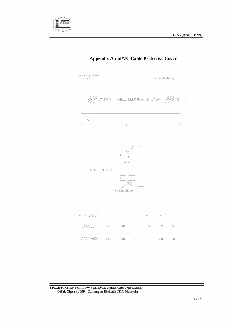
If uPVC cable protective covers are specified, the covers shall be ofpolyvinlcloride without plasticiser type with specific density between 1.37g/cm3 to 1.42 g/cm3 as shown in Appendix A approved by the S.O.’sRepresentative. The uPVC cover shall be resistant to aggressive soils andof dimension 150 mm wide and 1000 mm long. The covers shall be singlecoloured orange and top side shall be embossed with standard danger signand bold letters “BAHAYA! KABEL ELEKTRIK DI BAWAH”. Thecovers shall be provided with male and female interlocking device. The
L-S3 (April 1999)
SPECIFICATION FOR LOW VOLTAGE UNDERGROUND CABLE©Hak Cipta : 1999 Cawangan Elektrik JKR Malaysia
7/14
covers are laid together lengthwise from end to end along the entire cableroute and they are held together tightly by the interlocking device. At least25 mm overhang on each side of the cable shall be provided to protect thecable underneath.
The trench shall then be backfilled with earth and shall be consolidatedafter every 150 mm of backfilling using a mechanical rammer. An orangecoloured, multi-strand nylon rope of minimum 6 mm diameter shall be laidat a depth of 300 mm along the trench to identify the cable route. Atevery 10 metres interval, an extra 2 metres length of nylon rope shall becoiled and laid. The finished surface shall be left proud by 50 mm to allowfor subsidence and the Electrical Contractor shall be responsible for theremoval of any surplus to a position indicated by the S.O.'s Representative.
The surface of the refilled trench shall be temporarily reinstated andmaintained in a thoroughly safe condition until complete consolidation ofthe soil is achieved. As soon as the soil has consolidated, the trenchesshall be made good to the original conditions to the satisfaction of theS.O.'s Representative.
8.2 CABLE INSTALLED IN PRE-CAST CONCRETE TRENCHES
Method of installation of cables in pre-cast concrete trenches shall be inaccordance with Method 12, 18, 19 or 20 of Table 4A BS 7671. However, if the method is not specified, the cables shall be installed inaccordance with Method 18 and/or as directed by the S.O.'sRepresentative.
Cables laid at the bottom of the trenches shall be in accordance withMethod 18 of Table 4A BS 7671. Cables installed on the trench wall shallbe in accordance with Method 12, 19 or 20 of Table 4A BS 7671 and thecables shall be secured on the cable tray by means of saddles at suitableintervals. In the case of single core cable, non ferrous saddle shall be used.
The cable trays shall be fabricated from perforated hot dipped galvanisedsheet. The minimum thickness of the sheet steel used shall be 1.5 mm forcable tray with width up to 300 mm and shall be 2.0 mm for widthexceeding 300 mm. The cable tray shall be supported at least 25 mm from
L-S3 (April 1999)
SPECIFICATION FOR LOW VOLTAGE UNDERGROUND CABLE©Hak Cipta : 1999 Cawangan Elektrik JKR Malaysia
8/14
the trench wall by mild steel brackets at 600 mm intervals. The bracketshall be hot dipped galvanised. All brackets shall be securely fastened withsteel raw bolts and nuts. Samples of cable tray and bracket shall besubmitted to the S.O.'s Representative for approval prior to installation.
To provide electrical continuity, all cable tray joints shall be bridged bymeans of tinned copper tape of dimension not less than 25 mm x 3 mm. All saddles for cables on cable trays shall be installed by bolts, washers andnuts. All cable tray tees, intersection units, adaptor units etc. shall befactory manufactured.
The trenches inside the buildings shall be filled with clean sand up to alevel above the cable ducts.
8.3 CABLE RUN ON WALLS AND UNDER FLOOR SLABS
Cable run on walls and under floor slabs shall be mounted on perforatedhot dipped galvanised sheet steel cable trays. Method of installation of thecables shall be in accordance with Method 11 and 12 of Table 4A BS7671. The construction and finished of the cable trays and the way ofinstallation of the cables on the cable trays shall be as described in 8.2above.
The cable trays shall be suspended from floor slabs by hangers or mountedon wall by brackets at 600 mm interval. The material and finishes of thehangers, brackets and other suspending and supporting structures shall beas that described for brackets in 8.2 above.
Where cable trays pass through floors or fire resistant walls, thesurrounding hole shall be sealed to full thickness of the floor or wall withnon-hygroscopic fire-resisting material of minimum 2-hour fire ratingapproved by Jabatan Bomba Dan Penyelamat Malaysia.
9.0 CABLE TERMINATION AND JOINTING
Unless otherwise permitted, all cable termination and jointing works shall
L-S3 (April 1999)
SPECIFICATION FOR LOW VOLTAGE UNDERGROUND CABLE©Hak Cipta : 1999 Cawangan Elektrik JKR Malaysia
9/14
only be carried out in the presence of the S.O.'s Representative. A plasticlaminated plate engraved with details such as size of cable, number ofcore, date of commissioning, date of jointing, length of cable, distance ofcable joint etc. shall be securely fixed near the termination. All cableterminations and jointing shall be undertaken by competent persons asprescribed in Electricity Regulations 1994.
9.1 TERMINATION OF PVC INSULATED ARMOURED CABLE
PVC/SWA/PVC, XLPE/SWA/PVC, XLPE/AWA/PVC, and XLPE/PVCcable shall be provided with compression cable gland for termination. Thecable gland shall be of gunmetal or brass type and shall grip both the innerand outer PVC sheath of the cable and so designed that any strain on thecable is taken by the steel wire armouring which shall be effectively sealedbetween the gland itself and the outer cable sheath. If so directed by theS.O.’s Representative, termination by heat shrinkable method shall be usedas described in 9.2 hereafter.
9.2 TERMINATION OF PAPER INSULATED CABLE
Paper insulated cables, unless otherwise specified, shall be terminated bythe heat shrinkable method.
The cables shall be tested for moisture before termination is commenced. Samples of paper both from the layer nearest to and furthest from theconductor shall be immersed in transformer oil or paraffin wax, heated to atemperature of approximately 115 0C. If any residual moisture is presentthis will be immediately detected by bubbling. Samples of paper should betested singly and should not be touched by hand but gripped in a pair oftweezers. Phasing and insulation resistance tests shall be taken on eachlength of cable laid before termination is commenced.
The heat shrinkable termination materials used shall be supplied in acomplete kit to suit various sizes of cable and to provide stress control,non-tracking and environmentally sealed termination. It shall consist ofhigh permittivity, high resistivity, heat shrinkable, stress control, UVstable, non-tracking polymeric materials and heat activated sealant to
L-S3 (April 1999)
SPECIFICATION FOR LOW VOLTAGE UNDERGROUND CABLE©Hak Cipta : 1999 Cawangan Elektrik JKR Malaysia
10/14
prevent ingress of moisture and contamination. The termination shall meetthe performance test of IEC 60112, and identification of conductors bycolour shall comply with IEC 60446. It shall also have the followingperformance characteristics: -
(a) Voltage withstand for 15 minutes, 50 Hz : 4 KV phase to earth.
(b) Voltage withstand
for 4 hours, 50 Hz : 3 KV phase to earth. (c) Impulse voltage withstand
positive and 10 negative, micro seconds : 8 KV peak phase to earth.
(d) Continuous a.c.voltage : 1.5 KV phase to earth. (e) Insulation resistance
between phase conductorand ground : 1000 Megaohms or greater.
9.3 CABLE JOINTING
The type of cable boxes, compound and jointing materials used shall befactory manufactured. Unless otherwise specified cast iron joint boxesshall be used, and all jointing kits shall be approved by the S.O.’sRepresentative before joints being carried out. Every cable joint shall bestarted and finished on the same day. Whenever cables are to be jointed inthe open during wet weather conditions, the Electrical Contractor shalltake all necessary precautions to prevent moisture getting into the cables. When cable sheaths is used as earth continuity conductor, the glands musthave necessary contact surfaces to provide a low resistance path underfault conditions. Phasing and insulation resistance tests shall be takenbefore jointing is commenced.
Core numbers printed on the papers shall be observed when jointing andwhenever possible such numbers shall be maintained throughout the
L-S3 (April 1999)
SPECIFICATION FOR LOW VOLTAGE UNDERGROUND CABLE©Hak Cipta : 1999 Cawangan Elektrik JKR Malaysia
11/14
system. Core number 'O', '1', '2' and '3' shall denote as neutral, red, yellowand blue phases respectively. In the case of two core cable, number '1'shall denote the phase conductor and '0' the neutral. Crossing of core inthe boxes shall be avoided wherever possible but connections shall beconsistent with the foregoing requirements. The jointing of cables shall beundertaken only by competent cable jointer as prescribed in ElectricityRegulations 1994.
10.0 CABLE MARKERS
Cable marker with lettering and sign as shown in Appendix B1 andAppendix B2 shall be provided by the Electrical Contractor at everychange in direction of underground cable routes and at every 15 m onstraight run. Cable markers shall be of heavy duty reinforced concreteconstruction and approved by the S.O.'s Representative.
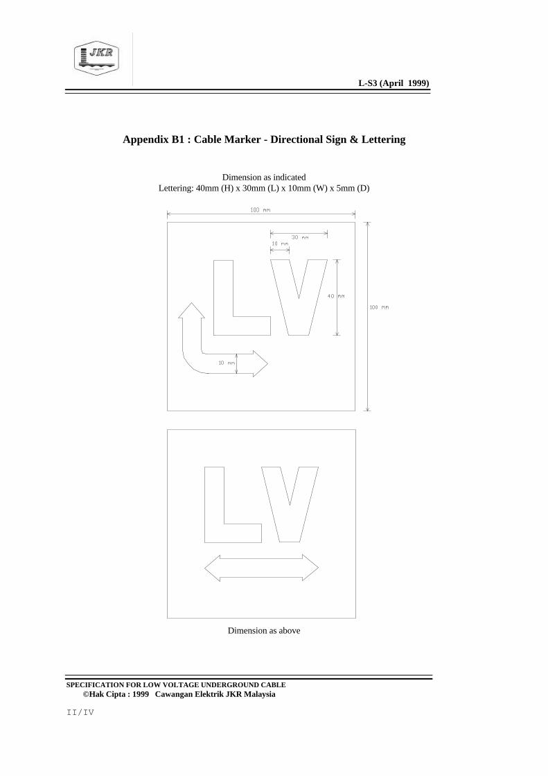
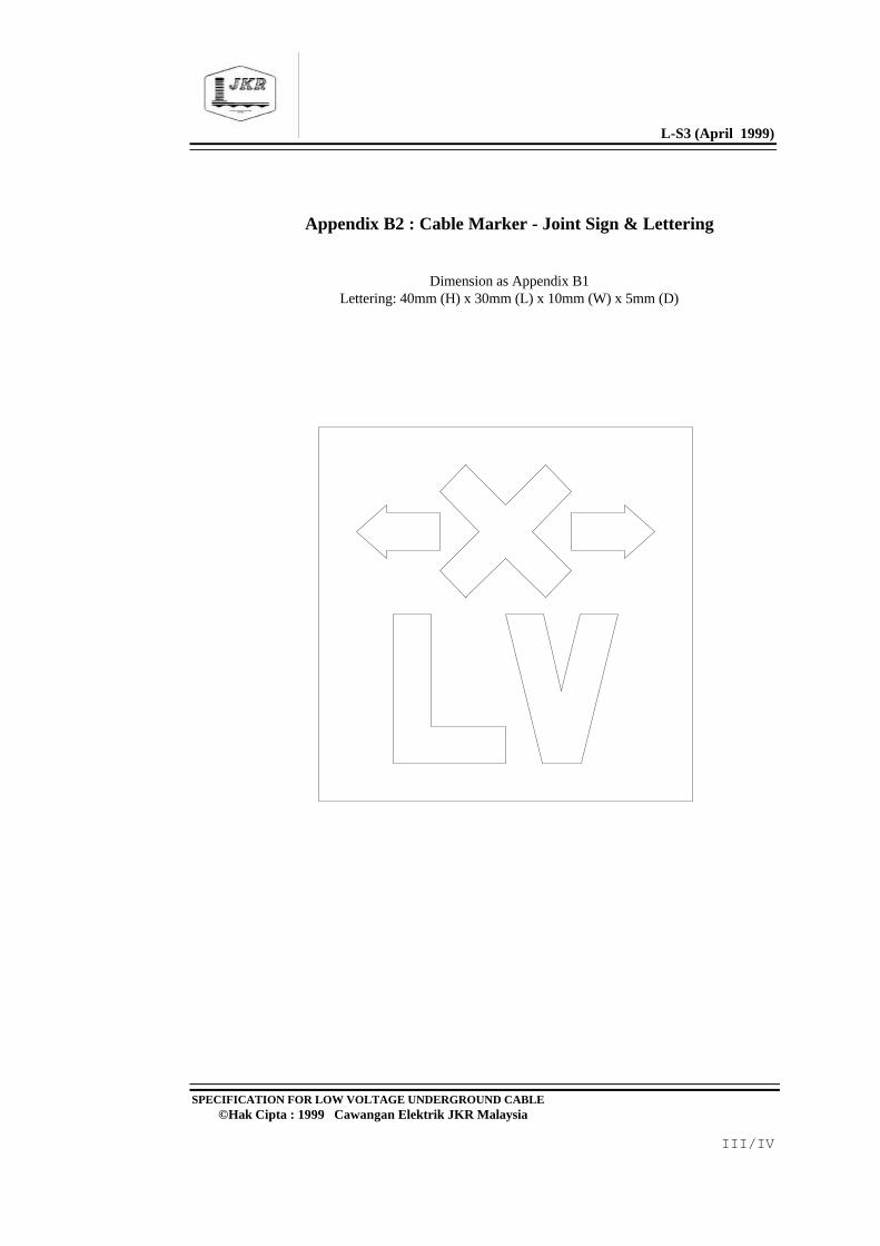
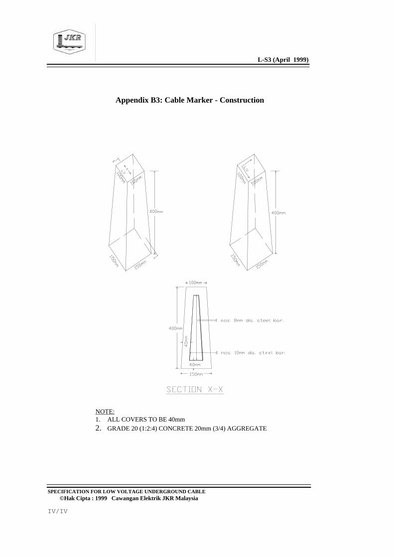
The cable marker shall be of trapezoidal block with 100 mm square topface, 150 mm square bottom face and 400 mm in height as shown inAppendix B3. The top face shall be indented with bold lettering 'L.V.' anddirectional sign indicating the direction/directions of the cable route. Thecable marker shall be fully painted orange using standard road paint. Thecable marker shall be buried to a depth of 300 mm. Cable joint marker ofsimilar construction but with the lettering and sign as shown in AppendixB3 shall be provided and installed at every cable joint in the similarmanner.
11.0 TESTING AND COMMISSIONING
The Electrical Contractor shall be responsible for the testing of the cables. Tests shall include continuity, phasing out and insulation resistancebetween conductors and between conductors and sheath by employing a500 volts insulation tester. A copy of test results certified by competentperson shall be submitted to the S.O.’s Representative. The date ofcommissioning shall be agreed by the S.O.'s Representative and theElectrical Contractor shall ensure that the installation is safe before the
L-S3 (April 1999)
SPECIFICATION FOR LOW VOLTAGE UNDERGROUND CABLE©Hak Cipta : 1999 Cawangan Elektrik JKR Malaysia
12/14
cable is energised.
The S.O.'s Representative reserves the right to be present at all tests and theElectrical Contractor shall give at least one week notice in writing to the S.O.'sRepresentative for this purpose. In any case, no test shall be carried outwithout prior approval of the S.O.'s Representative. Copies of all the testcertificates together with as-installed Drawings properly bound and titled shallbe submitted to the S.O.'s Representative within one week after the completionof the testing.
12.0 MAINTENANCE
During the Defects Liability Period the Electrical Contractor shall performmaintenance work for the complete cabling and associated work. All worklabour, materials, tools and parts necessary to rectify the defects due tomanufacturing or installation fault shall be supplied and/or executed at noextra cost to the Government. The maintenance work shall be carried outas soon as the Electrical Contractor has been informed by S.O.'sRepresentative.
The work to be performed shall include but not limited to the following: -
(a) Replace or make good any defective cables, cable joints and cableterminations;
(b) Replace any broken or defective cable markers; (c) Making good any damage to building, concrete areas, slopes,
drains, culverts, existing cables, pipes etc. which had not beenproperly made good arising out of his work;
(d) Any other work deemed necessary by the S.O.'s Representative.
L-S3 (April 1999)
SPECIFICATION FOR LOW VOLTAGE UNDERGROUND CABLE©Hak Cipta : 1999 Cawangan Elektrik JKR Malaysia
13/14
13.0 SHOP DRAWINGS AND AS INSTALLED DRAWINGS
13.1 SHOP DRAWINGS
Two sets of prints of shop drawings for cable installation shall be submitted tothe S.O.’s Representative for approval. The Electrical Contractor shallprepare and submit shop drawings for the whole work or parts of the work atleast two weeks before the work begins. If the shop drawings submitted arenot acceptable by the S.O.’s Representative, the Electrical Contractor shallamend and re-submit the shop drawings within two weeks from the date ofreturn of the shop drawings.
The shop drawings shall include and show the following:
(a) The dimensioned general arrangements, layouts and positionsof cable trenches and cable ducts;
(b) The dimensioned general arrangements, layouts and routes of
cable trays; (c) The dimensioned layouts and positions of all holes and cut-
through in the walls and floors for the lateral and vertical cablemains and/or submains;
(d) The dimensioned layouts and positions of cable routes for all
cables laid underground, in ducts and trenches; (e) The dimensioned general arrangements, layout and positions of
cable joints.
The cost of all these shop drawings, whether or not provided in the Bill ofQuantities, is deemed to be included in the Contract.
13.2 AS INSTALLED DRAWINGS
Within three calendar months after the practical completion of thecontract, one set of true to scale negatives (110/115 gm/sq. m) and four
L-S3 (April 1999)
SPECIFICATION FOR LOW VOLTAGE UNDERGROUND CABLE©Hak Cipta : 1999 Cawangan Elektrik JKR Malaysia
14/14
set of prints showing the cable routes with reference to easily recognisablebuildings and structures, size and type of cables, location and type of jointetc shall be submitted. The drawing size shall be AO or A1 unlessotherwise approved by S.O.'s Representative.
These drawings shall be properly stencilled and shall have at the lowerright hand corner the Electrical Contractor's name and address, date ofcommissioning, scale, drawing number, title and any other particulars asrequired by the S.O.'s Representative and the following particulars: -
JABATAN KERJA RAYACAWANGAN ELEKTRIKCONTRACT NO:TENDER NO:
The numbers for these drawings shall be obtained from the S.O.'sRepresentative.
If the drawings submitted are not acceptable to the S.O.'s Representativethe Electrical Contractor shall amend and re-submit the drawings withintwo weeks from the date of return of the drawings.
If required and specified elsewhere, in addition to the aforesaid negatives andprints, as installed drawings shall be stored in electronic media or any othermedia as specified. For electronic media they shall be either in floppy disksformat or CD rewritable (CD-RW) optical disks format as specified which canbe easily retrieved by computer. The software programme shall be AutoCADof latest release. Two sets or copies in either format as specified appropriatelytitled and stored in container or casing shall be submitted.
In addition to the above, one set of the drawing shall be properly framedup in the switchroom.
* * * * * * * * * * * * * * * * * * * * * * * * * * * * * * *
L-S3 (April 1999)
SPECIFICATION FOR LOW VOLTAGE UNDERGROUND CABLE©Hak Cipta : 1999 Cawangan Elektrik JKR Malaysia
I/IV
Appendix A : uPVC Cable Protective Cover
L-S3 (April 1999)
SPECIFICATION FOR LOW VOLTAGE UNDERGROUND CABLE©Hak Cipta : 1999 Cawangan Elektrik JKR Malaysia
II/IV
Appendix B1 : Cable Marker - Directional Sign & Lettering
Dimension as indicatedLettering: 40mm (H) x 30mm (L) x 10mm (W) x 5mm (D)
Dimension as above
L-S3 (April 1999)
SPECIFICATION FOR LOW VOLTAGE UNDERGROUND CABLE©Hak Cipta : 1999 Cawangan Elektrik JKR Malaysia
III/IV
Appendix B2 : Cable Marker - Joint Sign & Lettering
Dimension as Appendix B1Lettering: 40mm (H) x 30mm (L) x 10mm (W) x 5mm (D)
L-S3 (April 1999)
SPECIFICATION FOR LOW VOLTAGE UNDERGROUND CABLE©Hak Cipta : 1999 Cawangan Elektrik JKR Malaysia
IV/IV
Appendix B3: Cable Marker - Construction
NOTE:1. ALL COVERS TO BE 40mm2. GRADE 20 (1:2:4) CONCRETE 20mm (3/4) AGGREGATE