Embed Size (px)
Citation preview

ISO 9001:2015 Document no: IRS:T-48 Version 1.1 Date Effective: / /
Document Title: TECHNICAL SPECIFICATIONSFORTRACK BASED LUBRICATORS(ELECTRONIC & HYDRAULIC TYPE)
Prepared By: JE/Design/Track
Checked By: ADE/Track/RF
Issued By: Director/Track-I
Page 1 of 28
भारत सरकार रेल मतं्रालय
Government of India MINISTRY OF RAILWAYS
TECHNICAL SPECIFICATIONSFORTRACK BASED LUBRICATORS
(ELECTRONIC & HYDRAULIC TYPE)
Specification No. IRS:T-48
Amendment History
S. No.
Month of Issue Version Reason of Amendment
1 June,2013 1.0 First Issue of Specification
2 1.1 Inclusion of ACS 1 & Para Related to Service Contract
Issued in
TRACK DESIGN DIRECTORATE RESEARCH DESIGN AND STANDARDS ORGANISATION
MANAK NAGAR, LUCKNOW-226011

ISO 9001:2015 Document no: IRS:T-48 Version 1.1 Date Effective: / /
Document Title: TECHNICAL SPECIFICATIONSFORTRACK BASED LUBRICATORS(ELECTRONIC & HYDRAULIC TYPE)
Prepared By: JE/Design/Track
Checked By: ADE/Track/RF
Issued By: Director/Track-I
Page 2 of 28
CONTENTS
Para No.
Description Page No.
- Preface
Technical Specification Of Track Based Lubricators(Electronic Type)
1. Scope
2. Deviations
3. Service Conditions
4. Documents to be Supplied and Training
5. Function
6. System Description
7. Major Components Specifications
8. Lubricant
9. Documentation
10. Performance of Application System(Lubricator and Lubricant)
11. Responsibilities of Agency
12. Service Engineers
13. Inspection
14. Payment
15. Evaluation Process
Technical Specification Of Track Based Lubricators(Hydraulic Type)
1. Scope
2. Deviations
3. Service Conditions
4. Documents to be Supplied and Training
5. Function
6. System Description
7. Major Components Specifications
8. Lubricant
9. Documentation
10. Performance of Application System(Lubricator and Lubricant)
11. Responsibilities of Agency
12. Service Engineers
13. Inspection
14. Payment
15. Evaluation Process
LIST OF ANNEXURES
Annexure No.
Description Page no.
I Field Trial of Track Based Lubricators (Electronic)
II Field Trial of Track Based Lubricators (Hydraulic)

ISO 9001:2015 Document no: IRS:T-48 Version 1.1 Date Effective: / /
Document Title: TECHNICAL SPECIFICATIONSFORTRACK BASED LUBRICATORS(ELECTRONIC & HYDRAULIC TYPE)
Prepared By: JE/Design/Track
Checked By: ADE/Track/RF
Issued By: Director/Track-I
Page 3 of 28
PREFACE
1.0 Para 424 (2) of IRPWM provides that Track mounted gauge face lubricators
should be provided on curves of radius 875 m (2°) and sharper on Broad
Gauge to reduce rail gauge face wear. On routes where rail grinding is in
practice, track mounted automatic gauge face lubricators should be provided
on curves of radius 1400m (1.250) and sharper on Broad Gauge. Trial was
undertaken with hydraulic, electronic with AC power and electronic with solar
power lubricators on sharp curves in ghat sections. Based on experience of
trial and inputs from various stake holders, the “Technical specification for
Track Based Lubricators (Electronic & Hydraulic Type)” was prepared by
RDSO.
2.0 The Basic dispensing system of lubricant is almost similar for both Electronic
and Hydraulic types of lubricating systems. During Trial, it was observed that
electronic lubricators both with AC power and with solar power have exhibited
better control in dispensing the lubricant resulting in lesser wastage of
lubricant compared to hydraulic type. AC powered electronic lubricators can
be provided on electrified routes, while Solar powered electronic lubricators
can be provided on other routes. Hydraulic type lubricators may be provided
preferably on sections having less GMT where electricity is not available.
3.0 Railways shall arrange track mounted gauge face lubricators as per
requirement to meet the provisions of IRPWM through service contract. The
agency (RDSO approved firm only) would arrange, install on track and
commission the lubricator system as per Zonal Railway’s requirements and
will ensure its proper functioning during the service contract period. The scope
of work will be for minimum 3 years. While providing service to Zonal
Railways, agency would ensure that: -
(i) Adequate arrangement is made for Lubricant to be used with
lubricators to avoid idling. Performance Parameters of Lubricant to be
used in Lubricators have been laid down in the specification.
(ii) Availability of friction measurement equipment shall be ensured for
measurement of coefficient of friction at gauge face corner of outer rail
of curve to judge the efficacy of lubricant and lubricators installed for
the purpose, as specified.
(iii) Adequate arrangements for operation and maintenance of lubricators
including supply of consumables and spare parts as required. The
entire cost of operation and maintenance would be borne by the
agency.

ISO 9001:2015 Document no: IRS:T-48 Version 1.1 Date Effective: / /
Document Title: TECHNICAL SPECIFICATIONSFORTRACK BASED LUBRICATORS(ELECTRONIC & HYDRAULIC TYPE)
Prepared By: JE/Design/Track
Checked By: ADE/Track/RF
Issued By: Director/Track-I
Page 4 of 28
TECHNICAL SPECIFICATION OF TRACK BASED LUBRICATORS
(Electronic Type)
1.0 SCOPE
This specification covers the description, functional and
performanceparameters of electronic track based lubricators for gauge
face lubrication. The delivery system should be specifically designed to
apply lubricant on curves under different environmental and traffic
conditions on Indian Railways.
2.0 DEVIATIONS
The tenderer shall furnish compliance or deviations, if any, for each
clause and sub clause of the specifications along with technical
explanations/details. The tenderer shall also furnish financial implications
of the deviations if any.
3.0 SERVICE CONDITIONS
3.1 System should be able to work under following service conditions:
i) Ambient temperature : 00C to 50 0C
ii) Rail temperature : (-)100C to (+) 750C
iii) Humidity : 40-100%
iv) Rainfall : Fairly heavy
v) Atmospheric condition : Very dusty, heavy fog
3.2 On IR network the electrified traction consists of overhead electric
system of either 25000 V AC or 1500 V DC with residual return current
passing through one of the rails in the track. The voltage for track circuits
for signalling purpose is up to 12 volts and the corresponding current
upto 1 amp. passes through the other rail. The lubricator system should
be able to work in above stated electric traction and signalling system
and its induction effect.
3.3 The lubricator system should be such that it does not affect the signalling
system.
3.4 The firm should offer proven technology with lubricator and lubricant
supplied by them and working satisfactorily in any reputed railway
system of the world of similar environment prevailing in India. Certificate
in this regard from relevant railway system shall be furnished.
3.5 At the time of installation of lubricator system, the lubricator system
would not be older than 5 years.
4.0 DOCUMENTS TO BE SUPPLIED AND TRAINING
i. Installation Manual
ii. Maintenance Manual
iii. Service Manual

ISO 9001:2015 Document no: IRS:T-48 Version 1.1 Date Effective: / /
Document Title: TECHNICAL SPECIFICATIONSFORTRACK BASED LUBRICATORS(ELECTRONIC & HYDRAULIC TYPE)
Prepared By: JE/Design/Track
Checked By: ADE/Track/RF
Issued By: Director/Track-I
Page 5 of 28
iv. Part Manual
v. Action Plan for providing the services
Necessary training required to Railway officials for monitoring of performance of the equipment would be imparted by the agency.
5.0 FUNCTION
The applicator system should be an electrically powered pumping system for delivering an adjustable quantity of lubricating material to the rails in a manner such that passing wheels, either all or nominated would carry the designed amount of lubricant along the gauge face of rails.
6.0 SYSTEM DESCRIPTION
The application system must be proven system and should be functional in all climatic conditions in India.
The application system should consist of a rail-mounted sensor, a control box, an AC to DC converter or solar-charged battery, a motor, a pump, a tank with a cover and a material distribution system of hoses and applicators attached to the rails. The whole system should be compatible with the lubricant as defined in para 8.0 of this specification.
The system should operate as passing wheels enter magnetic or such field of the rail-mounted sensor. The sensor should transmit a signal back to the control box. After counting the number of signals from the sensor and when the pre-selected total is reached, the control box should turn on the pump for the pre-selected duration. The material should be pumped through a main hose to a central distribution manifold where it may split into distribution hoses that connect to the multi-ported applicators, clamped to the rail i.e. the application of the lubricant to the rail should be of non-squirting type. The product should then travel to the dispensing ports of each applicator to deliver controlled amounts of product onto the rails. The product should then be picked-up by passing train wheels. The arrangement should be such that the optimum product distribution takes place both along circumference of wheel flange as well as longitudinally along gauge face of rail.
7.0 MAJOR COMPONENT SPECIFICATIONS
7.1 Wheel Sensor
Wheel passage should be determined by a disturbance to the localized magnetic flux or such field established by the sensor. Disturbance of the magnetic flux or such field should induce a voltage signal indicating a passing wheel.
Assembly to the rail should not require machining of the rail.
The control circuit should be designed to accept voltage signals for speeds as low as 10 kmph and should be able to function properly up to speed of 200 kmph.
ISO 9001:2015 Document no: IRS:T-48 Version 1.1 Date Effective: / /
Document Title: TECHNICAL SPECIFICATIONSFORTRACK BASED LUBRICATORS(ELECTRONIC & HYDRAULIC TYPE)
Prepared By: JE/Design/Track
Checked By: ADE/Track/RF
Issued By: Director/Track-I
Page 6 of 28
Sensors should be available from the equipment manufacturer in configuration allowing for (1) bi-directional traffic without specialrequirements, (2) for use in environments where stray currents from power lines or buried cables may cause false detection of wheel passage, and (3) single-direction traffic activation.
7.2 Power Supply
Application system should be designed to operate either with direct electrical connection to AC power source or independently using a solar panel and battery.
(a) AC Power
Unit should also be workable with 230 volts, 50Hz. Supply. It
should be able to withstand voltage fluctuation in the range of
180-260 volts.
(b) Solar Power
The unit should be supplied with a solar panel and battery system.
The solar panel should be able to charge a sealed, deep-cycle,
battery designed for extended use outdoors without high wattage
recharging. Erection of solar panel should be done in a manner so
as to prevent vandalism. To prevent theft / for protection of solar
panel it should be mounted on minimum 8.5 meter high mast,
suitably protected by barbed wires or other suitable means. Solar
panel should also be protected against damage from brick batting
etc.
The solar panel post should be fixed on suitably designed
foundation and provided with lightening protection arrangement, if
required. Solar panel post should be enclosed / surrounded by
masonry wall with wire fencing on its top.
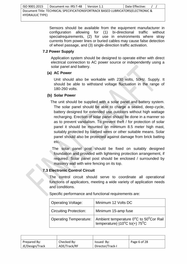
7.3 Electronic Control Circuit
The control circuit should serve to coordinate all operational
functions of applicators, meeting a wide variety of application needs
and conditions.
Specific performance and functional requirements are:
Operating Voltage: Minimum 12 Volts DC
Circuiting Protection: Minimum 15-amp fuse
Operating Temperature: Ambient temperature 0oC to 500Cor Rail temperature(-)10oC to(+) 750C

ISO 9001:2015 Document no: IRS:T-48 Version 1.1 Date Effective: / /
Document Title: TECHNICAL SPECIFICATIONSFORTRACK BASED LUBRICATORS(ELECTRONIC & HYDRAULIC TYPE)
Prepared By: JE/Design/Track
Checked By: ADE/Track/RF
Issued By: Director/Track-I
Page 7 of 28
Enclosures: NEMA 4 Rated or equivalent
Sensitivity:
Factory Set A 3.5 Volts DC (may be adjusted lower to accommodate slower speed trains, with a corresponding sacrifice of accuracy)
Counter Circuit: Should activate counter with every passage of wheel. It should be possible to incorporate a skip count feature to activate motor selectively after passage of selected number of wheels so as to minimize the consumption of lubricant and maximize use of lubricant applied.
Timer Circuit: Should allow selection of variably timed motor activation cycle for maximizing the utilization of lubricant applied and minimize its consumption. Circuit should also provide for a constant setting used to prime the system.
The control circuit should have the capability to operate the motor for
traffic in both directions or in a single direction when used with the
appropriate wheel sensor.
For security of the installation, the tank lid should be openable to
access the controls but duly locked. The vendor has to provide
satisfactory solution to make complete unit theft/vandalism proof and
safety against damage to any part of the equipment. The steel tank
containing the complete equipment including control panel etc.
should be enclosed with suitable fencing system having separate
door with lock and key arrangements. The above planning and
execution of work is to be done by vendor himself along with
installation of the equipment. If required, vendor is to submit the
necessary drawings to comply this requirement.
The system should have separate controls to allow the selection of
the interval, based on wheel counts, between each activation and to
select the duration of the motor "on" cycle.
The motor should be capable of activation on demand for
maintenance and test purposes.
A signal lamp should illuminate when motor is activated and another
to illuminate when the sensor is tripped.

ISO 9001:2015 Document no: IRS:T-48 Version 1.1 Date Effective: / /
Document Title: TECHNICAL SPECIFICATIONSFORTRACK BASED LUBRICATORS(ELECTRONIC & HYDRAULIC TYPE)
Prepared By: JE/Design/Track
Checked By: ADE/Track/RF
Issued By: Director/Track-I
Page 8 of 28
It should have arrangement for anti-vandalism and anti-theft
features.
7.4 Electric Motor
The electric motor powering the pump should be directly coupled to
the pump and designed to operate on minimum 12 volts DC. Electric
motor should incorporate a suitable arrangement to coordinate with
the speed requirements of the pump.
7.5 Pump
The pump should be efficient and compact It should require little and
easy maintenance and also easy to prime. Pump should be capable
of handling a wide range of viscosities, from the stiffest of lubricant to
the most fluid one. Pump should be able to produce adequate
minimum pressure required for pumping the desired quantity of
lubricant from the lubricant chamber to track rail gauge face for
various lifts/heights as per site conditions during passage of train
and to perform all the functions of gauge face lubricator. Pump
should be mounted in such a way that the pump's inlet port mates
directly to tank's outlet near bottom of tank. Between the pump and
material there should be a large mesh screen. The supplier will
submit the detailed specifications of pump for technical scrutiny of
the offer.
7.6 Lubricant Distribution System
Shut off valve or any other suitable lubricant distribution system
should be used to control the flow of lubricant to the applicators.
Distribution system should be efficient, able to distribute the lubricant
evenly. It should preferably have minimum moving parts. It should
require minimum and easy maintenance.
7.7 Hose
Hoses used with the application system should be connected via
screw-type connections to the tank and manifold.
Specific performance and functional requirements are:
Outlet hose May be wire-braided
Distribution hoses Must be non-conductive type hose.
Inner Tube Suitable Oil Resistant Material
Cover Construction Suitable Oil Resistant Material

ISO 9001:2015 Document no: IRS:T-48 Version 1.1 Date Effective: / /
Document Title: TECHNICAL SPECIFICATIONSFORTRACK BASED LUBRICATORS(ELECTRONIC & HYDRAULIC TYPE)
Prepared By: JE/Design/Track
Checked By: ADE/Track/RF
Issued By: Director/Track-I
Page 9 of 28
Reinforcement: Suitably reinforced
Temperature Range: Ambient temperature 0oC to 50oCor Rail temperature(-)10oC to(+) 75oC
Burst Press Min: 84.37 Kgf/cm2(1200 Psi)
Fittings: Cast or forged brass alloy end fittings with cast or spun brass ferrules.
Manifold valve handles should be removable for easy storage in the dry
chamber of the tank.
Distribution hoses should be long enough to supply applicators
mounted to the rails.
7.8 Tank
Tank should be made of all welded steel construction and preferably
should include a separate section from the material to hold the
control box, power supply, and motor/pump etc. to improve
protection against vandalism.
Tank lid will include provisions for a locking mechanism to prevent
unauthorised access to the tank and controls.
Each tank should be fitted with a seal to prevent entry of any foreign
material, snow, sand, rain or other wind-born particulate matter. The
seal should have the arrangement to allow easy field replacement, if
necessary. The bottom and sides of the tank should be such that it
aids to easy flow of the material to the pump.
Tanks should include lifting lugs. The minimum Capacity of tank for
storage of lubricant should be such that refilling would usually not be
required in less than 3 months subject to a minimum of 50 Kg.
7.9 Applicators
The application bars should clamp securely to the rail and be
adjustable for different sizes of rails being used in India and
distribution configurations. It should have coverage of minimum 1
Km or 2 Km as the case may be with the recommended high quality
rail-road lubricant. Temperature range should be same as for hose.
All bars should mount to rail in such a way so as to minimise the
wastage of material from leakage around mounting.
The applicators should be multi-port (minimum 10 ports per
applicator) configuration designed to deposit material uniformly along

ISO 9001:2015 Document no: IRS:T-48 Version 1.1 Date Effective: / /
Document Title: TECHNICAL SPECIFICATIONSFORTRACK BASED LUBRICATORS(ELECTRONIC & HYDRAULIC TYPE)
Prepared By: JE/Design/Track
Checked By: ADE/Track/RF
Issued By: Director/Track-I
Page 10 of 28
the length of the applicator. Internally, each applicator should
incorporate passageways designed so as to equally balance
distribution from each port opening. These passageways should be
finished such as to minimize sticking and clogging of material within
the applicators.
Gauge face lubrication applicators should be mounted such that
gauge face lubricant is deposited on to the upper portion of the rail’s
gauge face so as to come in contact with wheel flange.
8.0 LUBRICANT
A suitable lubricant for heavy rail road traffic should be used
which is compatible with the system. Its lubricity should be such that
it shall be capable of providing a value of Coefficient of friction not
greater than 0.25 on the gauge face corner of rail. Coefficient of
friction will be measured by a calibrated Tribometer/Tribotester.
The lubricant should be non-inflammable, non-toxic and non-health
hazard. It should not give adverse effect on rolling stock components
and track components i.e. rails, sleepers, fastenings, ballast etc.
Lubricant should be resistant to both water and high temperature. It
should not get washed away in rain/moist conditions and also should
not get softened or run down during high temperatures prevailing in
the country.
The agency will give detailed specifications of lubricant to comply the
above requirement and scrutiny of the offer. The agency will also
furnish the average consumption rate of lubricant per actuating
wheel for all types of lubricant suitable for the equipment being
offered.
8.1 Rail condition:Lubrication should be done on new rails or on old rails
which do not have Gauge Corner Cracking or head checks.
9.0 DOCUMENTATION
9.1 Documentation of the track based lubricator system should be supplied
comprising of detail of diagram, electrical and electronic designs with
descriptions, component materials/part number, equivalent international
part number, component specification etc. along with explanatory notes
and comments wherever necessary.
9.2 Calibration, operation, maintenance and troubleshooting manuals
should be prepared in detail to the satisfaction of purchaser and
supplied in six copies each.
9.3 Record of specification of Lubricant used, its frequency of filing in the
tank, consumption rate etc. and performance of equipment in terms of

ISO 9001:2015 Document no: IRS:T-48 Version 1.1 Date Effective: / /
Document Title: TECHNICAL SPECIFICATIONSFORTRACK BASED LUBRICATORS(ELECTRONIC & HYDRAULIC TYPE)
Prepared By: JE/Design/Track
Checked By: ADE/Track/RF
Issued By: Director/Track-I
Page 11 of 28
coefficient of friction and carry down effect shall be maintained on
regular basis by the agency.
10.0 Performance of application system (Lubricator and Lubricant):
Performance of the application system (Lubricator and Lubricant) would
be evaluated in terms of the ‘Carry Down Effect’.
Carry down effect is the distance from the location of applicator fixed in
the track in the intended direction up to which lubricant should be carried
by the wheel flange effectively to reduce the rail wear. Lubricator should
be located on tangent track at the beginning of transition curve where
wheel flanging is just beginning to occur. On single lines, the lubricator
shall be located in the direction of heaviest traffic.
The coefficient of friction at gauge face corner of outer rail of curve
should not be greater than 0.25. To ascertain the efficacy of the
application system, coefficient of friction shall essentially be measured at
the farthest point of the carry down effect.
Outer rail of the entire curve length of similar flexure (LH or RH) within
the length of carry down effect should get lubricated for which applicator
has been installed. However, rail in the straight track, if available within
this stretch may not get lubricated. Lubricant should not come on the top
of the rail except for the near vicinity of the applicator. The carry down
effect will have the following two categories:
(i) 1 Km
(ii) 2 Km
Carry down effect of 1 Km category would be made use of only where
there is no other curve of similar flexure requiring lubrication in the
adjoining 1 Km in the intended direction.
Requirement for Application system falling in the above two categories
shall be made separate items in the Schedule of Work in the tender
document.
Coefficient of friction and carry down effect of lubricator shall be
measured at a frequency of one month or higher, depending on the site
conditions. No payment would be made for the period in which carry
down effect is not adequate as per these stipulations as determined by
measurement of coefficient of friction.
Note:-
Intended Direction:
Intended direction is the traffic direction in case of Double line whereas it
is heaviest traffic direction for Single line.
ISO 9001:2015 Document no: IRS:T-48 Version 1.1 Date Effective: / /
Document Title: TECHNICAL SPECIFICATIONSFORTRACK BASED LUBRICATORS(ELECTRONIC & HYDRAULIC TYPE)
Prepared By: JE/Design/Track
Checked By: ADE/Track/RF
Issued By: Director/Track-I
Page 12 of 28
11.0 Responsibilities of Agency:
11.1 The agency would ensure that system installed including all parts,
components etc. used is free from manufacturing, design, material, and
workmanship defects and should be of the highest quality and in
conformity with the specifications.
11.2 Any part of the rail lubricating unit failing or proving unsatisfactory in
service would be replaced by the agency at its own cost.
12.0 SERVICE ENGINEERS:
The agency should provide at his own expense the services of
competent engineers during the entire service period. Service
engineers should be available for commissioning of rail lubricators for
regular service, trouble free operation, repair and maintenance.
13.0 INSPECTION
13.1 The inspection of rail lubricators shall be carried out by the Zonal
Railways during installation of equipment.
13.2 Inspection for Performance monitoring will be carried out as per para
10.0 by Zonal Railways. Representative of service provider should
also be on site at the time of inspection.
14.0 Payment:
14.1 Coefficient of friction and carry down effect of lubricator shall be
measured at a frequency of one month or higher, depending on the
site conditions. Payment would be made on monthly basis subject
to adequate carry down effect and as per these stipulations as
determined by measurement of coefficient of friction.
14.2 In case the lubrication system fails to give service as specified in
para 10.0, no payment will be made to the agency for that period,
calculated on pro rata basis. In addition to this, penalty of 10% of
the payment as calculated above will also be imposed on the
agency.
15.0 Evaluation Process
Proforma for evaluating the performance of the Lubricator has been
attached as Annexure I for Electronic Type.

ISO 9001:2015 Document no: IRS:T-48 Version 1.1 Date Effective: / /
Document Title: TECHNICAL SPECIFICATIONSFORTRACK BASED LUBRICATORS(ELECTRONIC & HYDRAULIC TYPE)
Prepared By: JE/Design/Track
Checked By: ADE/Track/RF
Issued By: Director/Track-I
Page 13 of 28
TECHNICAL SPECIFICATION OF TRACK BASED LUBRICATORS
(Hydraulic Type)
1.0 SCOPE
This specification covers the description, functional and performance
parameters of hydraulic track based lubricators for gauge face
lubrication. The delivery system should be specifically designed to apply
lubricant on curves under different environmental and traffic conditions
on Indian Railways.
2.0 DEVIATIONS
The tenderer shall furnish compliance or deviations, if any, for each
clause and sub clause of the specifications along with technical
explanations/details. The tenderer shall also furnish financial implications
of the deviations if any.
3.0 SERVICE CONDITIONS
3.1 System should be able to work under following service conditions:
i) Ambient temperature : 00C to 50 0C
ii) Rail temperature : (-)100C to (+) 750C
iii) Humidity : 40-100%
iv) Rainfall : Fairly heavy
v) Atmospheric condition : Very dusty, heavy fog
3.2 On IR network the electrified traction consists of overhead electric
system of either 25000 V AC or 1500 V DC with residual return current
passing through one of the rails in the track. The voltage for track circuits
for signalling purpose is up to 12 volts and the corresponding current
upto 1 amp. passes through the other rail. The lubricator system should
be able to work in above stated electric traction and signalling system
and its induction effect.
3.3 The lubricator system should be such that it does not affect the signalling
system.
3.4 The firm should offer proven technology with lubricator and lubricant
supplied by them and working satisfactorily in any reputed railway
system of the world of similar environment prevailing in India. Certificate
in this regard from relevant railway system shall be furnished.
3.5 At the time of installation of lubricator system, the lubricator system
would not be older than 5 years.
4.0 DOCUMENTS TO BE SUPPLIED AND TRAINING
i. Installation Manual
ii. Maintenance Manual

ISO 9001:2015 Document no: IRS:T-48 Version 1.1 Date Effective: / /
Document Title: TECHNICAL SPECIFICATIONSFORTRACK BASED LUBRICATORS(ELECTRONIC & HYDRAULIC TYPE)
Prepared By: JE/Design/Track
Checked By: ADE/Track/RF
Issued By: Director/Track-I
Page 14 of 28
iii. Service Manual
iv. Part Manual
v. Action Plan for providing the services
Necessary training required to Railway officials for monitoring of performance of the equipment would be imparted by the agency.
5.0 FUNCTION
The applicator system should be a hydraulically powered pumping
system for delivering an adjustable quantity of lubricating material to the
rails in a manner such that passing wheels, would carry the desired
amount of lubricant along the gauge face of rails.
6.0 SYSTEM DESCRIPTION
The application system must be proven system and should be functional
in all climatic conditions.in India.
The application system should consist of an actuator, a pump, a tank
with cover, and a material distribution system of hoses and applicators
attached to the rails. The whole system should be compatible with the
lubricant as defined in para 8.0 of this specification.
The material should be pumped through main hose to a central
distribution manifold where it may split into distribution hoses that
connect to the multi-ported applicators clamped to the rail. The product
should then travel to the dispensing ports of each applicator to deliver
controlled amounts of product onto the rails. The product should then be
picked-up by passing train wheels. The arrangement should be such that
the optimum distribution of the product takes place both along
circumference of wheel flange as well as longitudinally along gauge face
of rails.
7.0 MAJOR COMPONENT SPECIFICATIONS
7.1 Actuator
It should be easy to install and easy to remove for servicing. It should
operate through a closed loop hydraulic system that delivers consistent
pressure. While it should be a wheel actuated actuator, the conversion
of train wheel energy into the impulses of hydraulic power must be
independent of train wheel speed.
It should be adjustable to compensate for train speed and wear on
head of rails. Also it should be bi-directional.

ISO 9001:2015 Document no: IRS:T-48 Version 1.1 Date Effective: / /
Document Title: TECHNICAL SPECIFICATIONSFORTRACK BASED LUBRICATORS(ELECTRONIC & HYDRAULIC TYPE)
Prepared By: JE/Design/Track
Checked By: ADE/Track/RF
Issued By: Director/Track-I
Page 15 of 28
7.2 Pump
It should be an efficient, compact and hydraulically powered motor
driving lubricant pump. It should require little maintenance and be easy
to prime. Pump should be capable of handling a wide range of
viscosities, from the stiffest of lubricant to the most fluid. Pump should
be able to produce adequate minimum pressure required for pumping
the desired quantity of lubricant from the lubricant chamber to track rail
gauge face for various lifts/heights as per site conditions during
passage of train and to perform all the functions of gauge face
lubricator. Pump should be mounted in such a way that the pump's inlet
port mates directly to tank's outlet near bottom of tank. Between the
pump and material there should be a large mesh screen. The supplier
will submit the detailed specifications of pump for technical scrutiny of
the offer.
7.3 Lubricant distribution system
Shut off valve or any other suitable lubricant distribution system should
be used to control the flow of lubricant to the applicators. Distribution
system should be efficient, able to distribute the lubricant evenly. It
should preferably have minimum moving parts. It should require
minimum and easy maintenance.
7.4 Hose
Hoses used with the application system should be connected via
screw-type connections to the tank and manifold. Specific performance
and functional requirements are:
Outlet hose: May be wire-braided.
Distribution hoses: Must be non-conductive type hose.
Inner Tube: Suitable Oil Resistant Material.
Cover Construction: Suitable Oil Resistant Material.
Reinforcement: Suitably reinforced.
Temperature Range Ambient temperature 0oC to 50oC
Or Rail temperature (-)10oC to(+) 75oC
Burst Press Min: 84.37 Kgf/cm2(1200 PSI)
Fittings: Cast or forged brass alloy end fittings with
cast or spun brass ferrules.

ISO 9001:2015 Document no: IRS:T-48 Version 1.1 Date Effective: / /
Document Title: TECHNICAL SPECIFICATIONSFORTRACK BASED LUBRICATORS(ELECTRONIC & HYDRAULIC TYPE)
Prepared By: JE/Design/Track
Checked By: ADE/Track/RF
Issued By: Director/Track-I
Page 16 of 28
Manifold valve handles should be removable for easy storage in the dry chamber of the tank.
Distribution hoses should be long enough to supply applicators mounted to the rails.
7.5 Tank
Tank should be made of all welded steel construction and preferably
should include a separate section from the material to hold the control
box, motor/pumps etc. The vendor has to provide satisfactory solution
to make complete unit theft/vandalism proof and safety against
damage to any part of the equipment. The steel tank containing the
complete equipment including control panel etc. should be enclosed
with suitable fencing system having separate door with lock and key
arrangements. The above planning and execution of work is to be
done by vendor himself along with installation of the equipment. If
required, vendor is to submit the necessary drawings to comply this
requirement.
Tank lid will include provisions for a locking mechanism to prevent
unauthorised access to the tank and controls.
Each tank should be fitted with a seal to prevent entry of any foreign
material, snow, sand, rain or other wind-born particulate matter. The
seal should have the arrangement to allow easy field replacement, if
necessary. The bottom and sides of the tank should be such that it
aids to easy flow of the material to the pump.
Tanks should include lifting lugs. The minimum Capacity of tank for
storage of lubricant should be such that refilling would usually not be
required in less than 3 months subject to a minimum of 50 Kg.
7.6 Applicators
The application bars should clamp securely to the rail and be adjustable for different sizes of rails being used in India and distribution configurations. It should have coverage of minimum 1 Km or 2 Km as the case may be with the recommended high quality rail-road lubricant. Temperature range should be same as for hose.
All bars should mount to rail in such a way so as to minimise the wastage of material from leakage around mounting.
The applicators should be multi-port (minimum 10 ports per applicator) configuration designed to deposit material uniformly along the length of the applicator. Internally, each applicator should incorporate passageways designed so as to equally balance distribution from each port opening. These passageways should be finished such as to minimize sticking and clogging of material within the applicators.

ISO 9001:2015 Document no: IRS:T-48 Version 1.1 Date Effective: / /
Document Title: TECHNICAL SPECIFICATIONSFORTRACK BASED LUBRICATORS(ELECTRONIC & HYDRAULIC TYPE)
Prepared By: JE/Design/Track
Checked By: ADE/Track/RF
Issued By: Director/Track-I
Page 17 of 28
Gauge face lubrication applicators should be mounted such that gauge
face lubricant is deposited on to the upper portion of the rail’s gauge
face so as to come in contact with wheel flange.
8.0 LUBRICANT
A suitable lubricant for heavy rail road traffic should be used which is
compatible with the system. Its lubricity should be such that it shall be
capable of providing a value of Coefficient of friction not greater than
0.25 on the gauge face corner of rail. Coefficient of friction will be
measured by a calibrated Tribometer/Tribotester.
The lubricant should be non-inflammable, non-toxic and non-health
hazard. It should not give adverse effect on rolling stock components
and track components i.e. rails, sleepers, fastenings, ballast etc.
Lubricant should be resistant to both water and high temperature. It
should not get washed away in rain/moist conditions and also should
not get softened or run down during high temperatures prevailing in the
country.
The agency will give detailed specifications of lubricant to comply the
above requirement and scrutiny of the offer. The agency will also
furnish the average consumption rate of lubricant per actuating wheel
for all types of lubricant suitable for the equipment being offered.
8.1 Rail condition: Lubrication should be done on new rails or on old rails
which do not have Gauge Corner Cracking or head checks.
9.0 DOCUMENTATION
9.1 Documentation of the track based lubricator system should be supplied
comprising of detail of diagram, electrical and electronic designs with
descriptions, component materials/part number, equivalent
international part number, component specification etc. along with
explanatory notes and comments wherever necessary.
9.2 Calibration, operation, maintenance and troubleshooting manuals
should be prepared in detail to the satisfaction of purchaser and
supplied in six copies each.
9.3 Record of specification of Lubricant used, its frequency of filing in the
tank, consumption rate etc. and performance of equipment in terms of
coefficient of friction and carry down effect shall be maintained on
regular basis by the agency.
10.0 Performance of application system (Lubricator and Lubricant):
Performance of the application system (Lubricator and Lubricant) would
be evaluated in terms of the ‘Carry Down Effect’.
Carry down effect is the distance from the location of applicator fixed in
the track in the intended direction up to which lubricant should be carried
by the wheel flange effectively to reduce the rail wear. Lubricator should
be located on tangent track at the beginning of transition curve where

ISO 9001:2015 Document no: IRS:T-48 Version 1.1 Date Effective: / /
Document Title: TECHNICAL SPECIFICATIONSFORTRACK BASED LUBRICATORS(ELECTRONIC & HYDRAULIC TYPE)
Prepared By: JE/Design/Track
Checked By: ADE/Track/RF
Issued By: Director/Track-I
Page 18 of 28
wheel flanging is just beginning to occur. On single lines, the lubricator
shall be located in the direction of heaviest traffic.
The coefficient of friction at gauge face corner of outer rail of curve
should not be greater than 0.25. To ascertain the efficacy of the
application system, coefficient of friction shall essentially be measured at
the farthest point of the carry down effect.
Outer rail of the entire curve length of similar flexure (LH or RH) within
the length of carry down effect should get lubricated for which applicator
has been installed. However, rail in the straight track, if available within
this stretch may not get lubricated. Lubricant should not come on the top
of the rail except for the near vicinity of the applicator. The carry down
effect will have the following two categories:
(iii) 1 Km
(iv) 2 Km
Carry down effect of 1 Km category would be made use of only where
there is no other curve of similar flexure requiring lubrication in the
adjoining 1 Km in the intended direction.
Requirement for Application system falling in the above two categories
shall be made separate items in the Schedule of Work in the tender
document.
Coefficient of friction and carry down effect of lubricator shall be
measured at a frequency of one month or higher, depending on the site
conditions. No payment would be made for the period in which carry
down effect is not adequate as per these stipulations as determined by
measurement of coefficient of friction.
Note:-
Intended Direction:
Intended direction is the traffic direction in case of Double line whereas it
is heaviest traffic direction for Single line.
11.0 Responsibilities of Agency:
11.1 The agency would ensure that system installed including all
parts, components etc. used is free from manufacturing, design,
material, and workmanship defects and should be of the highest quality
and in conformity with the specifications.
11.2 Any part of the rail lubricating unit failing or proving
unsatisfactory in service would be replaced by the agency at its own
cost.

ISO 9001:2015 Document no: IRS:T-48 Version 1.1 Date Effective: / /
Document Title: TECHNICAL SPECIFICATIONSFORTRACK BASED LUBRICATORS(ELECTRONIC & HYDRAULIC TYPE)
Prepared By: JE/Design/Track
Checked By: ADE/Track/RF
Issued By: Director/Track-I
Page 19 of 28
12.0 SERVICE ENGINEERS:
The agency should provide at his own expense the services of
competent engineers during the entire service period. Service
engineers should be available for commissioning of rail lubricators for
regular service, trouble free operation, repair and maintenance.
13.0 INSPECTION
13.1 The inspection of rail lubricators shall be carried out by the Zonal
Railways during installation of equipment.
13.2 Inspection for Performance monitoring will be carried out as per
para 10.0 by Zonal Railways. Representative of service provider
should also be on site at the time of inspection.
14.0 Payment:
14.1 Coefficient of friction and carry down effect of lubricator shall be
measured at a frequency of one month or higher, depending on the
site conditions. Payment would be made on monthly basis subject
to adequate carry down effect and as per these stipulations as
determined by measurement of coefficient of friction.
14.2 In case the lubrication system fails to give service as specified in
para 10.0, no payment will be made to the agency for that period,
calculated on pro rata basis. In addition to this, penalty of 10% of
the payment as calculated above will also be imposed on the
agency.
15.0 Evaluation Process
Proforma for evaluating the performance of the Lubricator has been
attached as Annexure II for Hydraulic Type.
********

ISO 9001:2015 Document no: IRS:T-48 Version 1.1 Date Effective: / /
Document Title: TECHNICAL SPECIFICATIONSFORTRACK BASED LUBRICATORS(ELECTRONIC & HYDRAULIC TYPE)
Prepared By: JE/Design/Track
Checked By: ADE/Track/RF
Issued By: Director/Track-I
Page 20 of 28
Annexure -I Field Trial of Track Based Lubricators (Electronic)
1. MANUFACTURING DETAILS :
i) Manufacturer’s/ Suppliers Name & Address
:
ii) No of Prototype Sample offered for trial
:
iii) Place of Installation : iv) Date of Installation :
v) Date of Inspection : vi) Sl. No. of equipment for test : vii)
Type of Category for Trial being conducted (1 Km or 2 Km)
:
viii) Make & Model :
2. Working Condition during type testing: (Compliance as per para no. 3.1 of specification to be submitted by firm)
a. Ambient Temperature- :
b. Rail Temperature :
c. Humidity :
d. Atmospheric Condition :
e. Rain fall
3. Track Features details :
Rly- Div. - Section- Sectional/Permissible Speed - Up/Down Line- SL/DL- Section Electrified (Yes/No): Rail (New/Old) –
Curve
Type/
No.
RH/
LH
Curve/
Straight
Degree/
Radius
Chainage Length
(m) repuS
poptaveleS
(mm)
Remarks
4.0 Major Component description:
SN Major Component Description Remark
1. Wheel Sensor -
Sensor Type
Assembly to the rail (weather require machining of the rail)

ISO 9001:2015 Document no: IRS:T-48 Version 1.1 Date Effective: / /
Document Title: TECHNICAL SPECIFICATIONSFORTRACK BASED LUBRICATORS(ELECTRONIC & HYDRAULIC TYPE)
Prepared By: JE/Design/Track
Checked By: ADE/Track/RF
Issued By: Director/Track-I
Page 21 of 28
Sensing Speed (10 to 200 kmph)
Allow bi-directional traffic without special requirements
Can sensor use in environments where stray currents from power lines or buried cables may cause false detection of wheel passage
single-direction traffic activation
2. Power Source - a) AC Power Supply
Unit workable with 230 volts, 50Hz
Ability to withstand voltage fluctuation in the range of 180-260 volts
b) Solar Power
Solar panel
Battery
Solar system working or not
3. Electronic Control Circuit -
Operating Voltage (Minimum 12 Volts DC)
Circuiting Protection (Minimum 15-amp fuse)
Operating Temperature (Ambient temperature 0°C to 50°C or Rail Temperature (-) 10°C to (+) 75°C)
Enclosures (NEMA 4 Rated or equivalent)
Sensitivity (Factory Set A 3.5 Volts DC (may be adjusted lower to accommodate slower speed trains, with a corresponding sacrifice of accuracy)
Provision for Counter Circuit
Provision for Timer Circuit
Provision in control circuit to operate for traffic in both direction or single direction
Arrangement for anti-vandalism and anti-theft features

ISO 9001:2015 Document no: IRS:T-48 Version 1.1 Date Effective: / /
Document Title: TECHNICAL SPECIFICATIONSFORTRACK BASED LUBRICATORS(ELECTRONIC & HYDRAULIC TYPE)
Prepared By: JE/Design/Track
Checked By: ADE/Track/RF
Issued By: Director/Track-I
Page 22 of 28
4. Electric Motor -
Operating Voltage (Minimum 12 Volts DC)
Provision for suitable arrangement to coordinate with the speed requirements of the pump
The motor should be capable of activation on demand for maintenance and test purposes
Provision of signal lamp for motor is activated and additional lamp for sensor is tripped.
5. Pump -
Easy to prime
Sufficient to produce adequate pressure
Weather inlet port mates directly tank outlet near bottom of tank
Availability of mess screen between pump and material
Weather details specification of pump provided by firm
6. Lubricant Distribution System -
Provision for control the flow of lubricant to the applicators
Distribution of the lubricant – evenly
7. Hose -
Screw-type connections
Outlet hose – wire braided
Distribution hoses- non-conductive type hose
Inner Tube- Suitable Oil Resistant Material
Cover Construction- Suitable Oil Resistant Material
Reinforced
Temperature Range – (certificate/compliance by firm)
Burst Press Min.- 84.37 Kgf/ cm2
ISO 9001:2015 Document no: IRS:T-48 Version 1.1 Date Effective: / /
Document Title: TECHNICAL SPECIFICATIONSFORTRACK BASED LUBRICATORS(ELECTRONIC & HYDRAULIC TYPE)
Prepared By: JE/Design/Track
Checked By: ADE/Track/RF
Issued By: Director/Track-I
Page 23 of 28
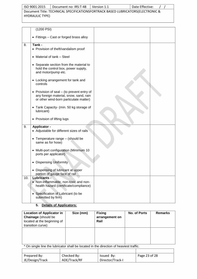
(1200 PSI)
Fittings – Cast or forged brass alloy
8. Tank -
Provision of theft/vandalism proof
Material of tank – Steel
Separate section from the material to hold the control box, power supply, and motor/pump etc.
Locking arrangement for tank and controls
Provision of seal – (to prevent entry of any foreign material, snow, sand, rain or other wind-born particulate matter)
Tank Capacity- (min. 50 kg storage of lubricant)
Provision of lifting lugs
9. Applicator -
Adjustable for different sizes of rails
Temperature range – (should be same as for hose)
Multi-port configuration (Minimum 10 ports per applicator)
Dispensing Uniformity
Dispensing of lubricant at upper portion of gauge face of rail
10. Lubricants -
Non-inflammable, non-toxic and non-health hazard (certificate/compliance)
Specification of Lubricant (to be submitted by firm)
5. Details of Applicators:
Location of Applicator in
Chainage (should be
located at the beginning of
transition curve)
Size (mm) Fixing
arrangement on
Rail
No. of Ports Remarks
* On single line the lubricator shall be located in the direction of heaviest traffic.
ISO 9001:2015 Document no: IRS:T-48 Version 1.1 Date Effective: / /
Document Title: TECHNICAL SPECIFICATIONSFORTRACK BASED LUBRICATORS(ELECTRONIC & HYDRAULIC TYPE)
Prepared By: JE/Design/Track
Checked By: ADE/Track/RF
Issued By: Director/Track-I
Page 24 of 28
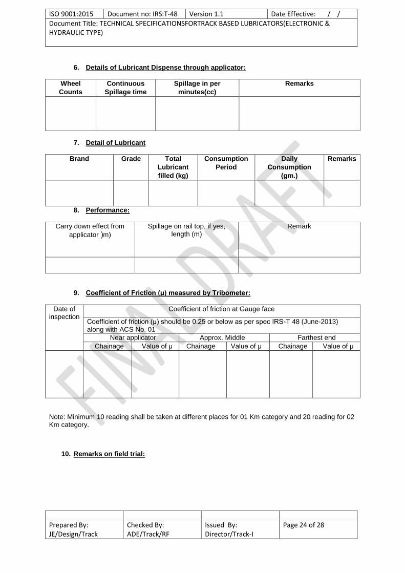
6. Details of Lubricant Dispense through applicator:
Wheel
Counts
Continuous
Spillage time
Spillage in per
minutes(cc)
Remarks
7. Detail of Lubricant
Brand Grade Total
Lubricant
filled (kg)
Consumption
Period
Daily
Consumption
(gm.)
Remarks
8. Performance:
Carry down effect from
applicator (m)
Spillage on rail top, if yes, length (m)
Remark
9. Coefficient of Friction (μ) measured by Tribometer:
Date of inspection
Coefficient of friction at Gauge face
Coefficient of friction (μ) should be 0.25 or below as per spec IRS-T 48 (June-2013) along with ACS No. 01
Near applicator Approx. Middle Farthest end
Chainage Value of μ Chainage Value of μ Chainage Value of μ
Note: Minimum 10 reading shall be taken at different places for 01 Km category and 20 reading for 02 Km category.
10. Remarks on field trial:

ISO 9001:2015 Document no: IRS:T-48 Version 1.1 Date Effective: / /
Document Title: TECHNICAL SPECIFICATIONSFORTRACK BASED LUBRICATORS(ELECTRONIC & HYDRAULIC TYPE)
Prepared By: JE/Design/Track
Checked By: ADE/Track/RF
Issued By: Director/Track-I
Page 25 of 28
Annexure -II Field Trial of Track Based Lubricators (Hydraulic)
1. MANUFACTURING DETAILS :
i) Manufacturer’s/ Suppliers Name & Address
:
ii) No of Prototype Sample offered for trial
:
iii) Place of Installation : iv) Date of Installation :
v) Date of Inspection : vi) Sl. No. of equipment for test : vii)
Type of Category for Trial being conducted (1 Km or 2 Km)
:
viii) Make & Model :
2. Working Condition during type testing: (Compliance as per para no. 3.1 of specification to be submitted by firm)
a. Ambient Temperature :
b. Rail Temperature :
c. Humidity :
d. Atmospheric Condition :
e. Rain fall :
3. Track Features details :
Rly- Div. - Section- Sectional/Permissible Speed - Up/Down Line- SL/DL- Section Electrified (Yes/No): Rail (New/Old) –
Curve
Type/
No.
RH/
LH
Curve/
Straight
Degree/
Radius
Chainage Length
(m) repuS
poptaveleS
(mm)
Remarks
4.0 Major Component description:
SN Name of Component
description Remarks
1 Actuator (yes/no)
Closed loop hydraulic system
ISO 9001:2015 Document no: IRS:T-48 Version 1.1 Date Effective: / /
Document Title: TECHNICAL SPECIFICATIONSFORTRACK BASED LUBRICATORS(ELECTRONIC & HYDRAULIC TYPE)
Prepared By: JE/Design/Track
Checked By: ADE/Track/RF
Issued By: Director/Track-I
Page 26 of 28
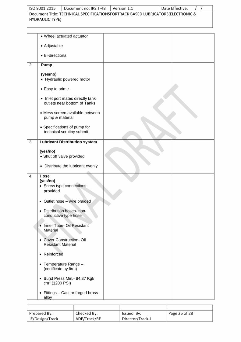
Wheel actuated actuator
Adjustable
Bi-directional
2 Pump (yes/no)
Hydraulic powered motor
Easy to prime
Inlet port mates directly tank outlets near bottom of Tanks
Mess screen available between pump & material
Specifications of pump for technical scrutiny submit
3 Lubricant Distribution system (yes/no)
Shut off valve provided
Distribute the lubricant evenly
4 Hose (yes/no)
Screw type connections
provided
Outlet hose – wire braided
Distribution hoses- non-conductive type hose
Inner Tube- Oil Resistant Material
Cover Construction- Oil Resistant Material
Reinforced
Temperature Range – (certificate by firm)
Burst Press Min.- 84.37 Kgf/ cm
2 (1200 PSI)
Fittings – Cast or forged brass alloy

ISO 9001:2015 Document no: IRS:T-48 Version 1.1 Date Effective: / /
Document Title: TECHNICAL SPECIFICATIONSFORTRACK BASED LUBRICATORS(ELECTRONIC & HYDRAULIC TYPE)
Prepared By: JE/Design/Track
Checked By: ADE/Track/RF
Issued By: Director/Track-I
Page 27 of 28
5 Tank (yes/no) Compete unit theft/vandalism
proof
Material of tank – Steel
Separate door with lock & key.
Drawings of Tank available
Tank fitted with seal
The minimum capacity of tank should be 50 kg
Lifting Lugs available
6 Applicator (yes/no) Adjustable for different sizes of
rails
Temperature range same as for hose
Multi-port configuration (Minimum 10 ports per applicator)
Dispensing Uniformity
Dispensing gauge face upper portion
7. Lubricants (yes/no)
Non-inflammable, non-toxic and non-health hazard ( if yes, certificate/compliance submitted)
Specification of Lubricants submitted (to be submitted by firm)
Consumption rate of lubricants per actuating wheel- calculation sheet provided by firm
5. Details of Applicators:
Location of Applicator
in Chainage(should be
located at the beginning
of transition curve)
Size (mm) Fixing
arrangement
on Rail
No. of Ports Remarks
ISO 9001:2015 Document no: IRS:T-48 Version 1.1 Date Effective: / /
Document Title: TECHNICAL SPECIFICATIONSFORTRACK BASED LUBRICATORS(ELECTRONIC & HYDRAULIC TYPE)
Prepared By: JE/Design/Track
Checked By: ADE/Track/RF
Issued By: Director/Track-I
Page 28 of 28
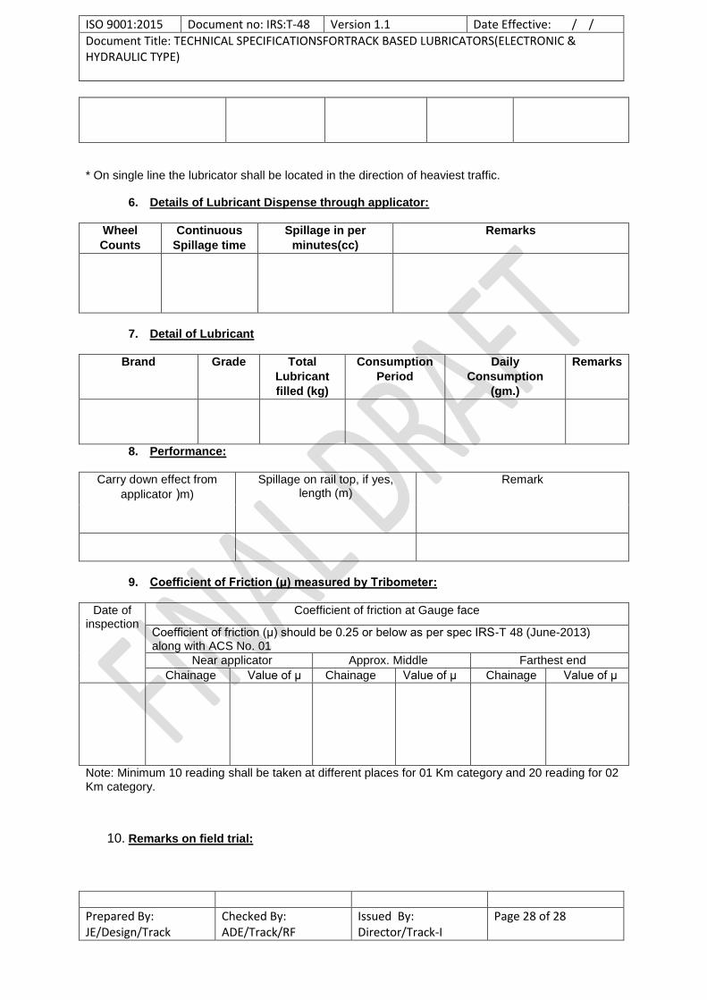
* On single line the lubricator shall be located in the direction of heaviest traffic.
6. Details of Lubricant Dispense through applicator:
Wheel
Counts
Continuous
Spillage time
Spillage in per
minutes(cc)
Remarks
7. Detail of Lubricant
Brand Grade Total
Lubricant
filled (kg)
Consumption
Period
Daily
Consumption
(gm.)
Remarks
8. Performance:
Carry down effect from
applicator (m)
Spillage on rail top, if yes, length (m)
Remark
9. Coefficient of Friction (μ) measured by Tribometer:
Date of inspection
Coefficient of friction at Gauge face
Coefficient of friction (μ) should be 0.25 or below as per spec IRS-T 48 (June-2013) along with ACS No. 01
Near applicator Approx. Middle Farthest end
Chainage Value of μ Chainage Value of μ Chainage Value of μ
Note: Minimum 10 reading shall be taken at different places for 01 Km category and 20 reading for 02 Km category.
10. Remarks on field trial: