Embed Size (px)
Citation preview
Specifications And
Requirements For
Gas Installations
Effective- February 2021

Directory of Company Offices
Central Hudson Gas & Electric Corp. Spec. and Req. for Gas Installations
This page was intentionally left blank.
Central Hudson Gas & Electric Corp.
Directory of Company Offices
Central Hudson Gas & Electric Corp. Spec. and Req. for Gas Installations
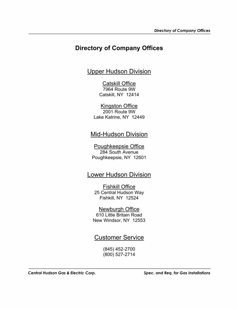
Directory of Company Offices
Upper Hudson Division
Catskill Office 7964 Route 9W
Catskill, NY 12414
Kingston Office 2001 Route 9W
Lake Katrine, NY 12449
Mid-Hudson Division
Poughkeepsie Office 284 South Avenue
Poughkeepsie, NY 12601
Lower Hudson Division
Fishkill Office 25 Central Hudson Way
Fishkill, NY 12524
Newburgh Office 610 Little Britain Road
New Windsor, NY 12553
Customer Service
(845) 452-2700 (800) 527-2714
Directory of Company Offices
Central Hudson Gas & Electric Corp. Spec. and Req. for Gas Installations
This page was intentionally left blank.
Central Hudson Gas & Electric Corp.
Section1 Introduction
Central Hudson Gas & Electric Corp. Specification and Requirements for Gas Installs
1
Table of Contents
1. INTRODUCTION .................................................................................................................. 5
1.1 PURPOSE .......................................................................................................................... 5 1.2 SCOPE .............................................................................................................................. 5 1.3 RATE SCHEDULES ............................................................................................................ 5 1.4 COOPERATION .................................................................................................................. 5 1.5 CODES .............................................................................................................................. 6 1.6 RESPONSIBILITY ............................................................................................................... 6 1.7 OBJECTIONABLE EQUIPMENT ........................................................................................... 6 1.8 REVISIONS ....................................................................................................................... 6
2. DEFINITIONS ................................................................................................................... 7-14
3. GENERAL INFORMATION AND REQUIREMENTS ..................................................... 15
3.1 APPLICATION FOR NATURAL GAS SERVICE ................................................................... 15 3.1.1 Accepted Format ....................................................................................................... 15 3.1.2 Required Lead-Time.................................................................................................. 15
3.2 PAYMENT OF FEES AND/OR DEPOSITS ............................................................................ 15 3.3 ACCESS .......................................................................................................................... 15 3.4 CHARACTER OF NATURAL GAS SERVICE ....................................................................... 16
3.4.1 Responsibility ............................................................................................................ 16 3.4.2 Natural Gas Characteristics ..................................................................................... 16
3.5 NEW NATURAL GAS SERVICE OR CONSTRUCTION ......................................................... 16 3.5.1 Installation Requirements ......................................................................................... 16
3.6 TEMPORARY SERVICE .................................................................................................... 16 3.6.1 General ..................................................................................................................... 16 3.6.2 Installation Requirements ......................................................................................... 17 3.6.3 Cost ........................................................................................................................... 17
3.7 EXCAVATION, CONSTRUCTION AND DEMOLITION NEAR COMPANY UNDERGROUND
FACILITIES ................................................................................................................................. 17 3.7.1 General ..................................................................................................................... 17 3.7.2 Responsibility ............................................................................................................ 17
3.8 WORK AUTHORIZATION ................................................................................................. 18
4 - 5 SERVICE PIPE INSTALLATIONS & METERING ............................................. 19-31
4.1 GENERAL ....................................................................................................................... 19 4.1.1 Service Pipe .............................................................................................................. 19 4.1.2 Route of Service ........................................................................................................ 19 4.1.3 Point of Service Termination .................................................................................... 19
Section1 Introduction
Central Hudson Gas & Electric Corp. Specification and Requirements for Gas Installs
2
4.1.4 Easements and Rights-of-Way .................................................................................. 19 4.2 CUSTOMER PIPING ......................................................................................................... 20
4.2.1 General ..................................................................................................................... 20 4.2.2 Distribution Piping ................................................................................................... 21 4.2.3 CSST Piping .............................................................................................................. 22 4.2.4 Press-Connect Fittings……………………………………………………………………...23
4.3 RELOCATION OF EXISTING COMPANY FACILITIES .......................................................... 23 4.4 URD SUBDIVISIONS ....................................................................................................... 23
4.4.1 General ..................................................................................................................... 23 4.4.2 Application Requirements ......................................................................................... 23 4.4.3 Additional Requirements ........................................................................................... 24
4.5 PRESSURE TESTING ........................................................................................................ 25
5. METERING .......................................................................................................................... 27
5.1 GENERAL ....................................................................................................................... 27 5.2 METER LOCATION .......................................................................................................... 27 5.3 MULTIPLE METERS ........................................................................................................ 28 5.4 CUSTOMER SERVICE VALVE .......................................................................................... 28 5.5 UNAUTHORIZED USE ...................................................................................................... 29 5.6 DEMOLITION .................................................................................................................. 29
6. ADEQUACY AND SAFETY OF INSTALLATION .......................................................... 31
6.1 GENERAL ....................................................................................................................... 31 6.2 LIABILITY ...................................................................................................................... 31 6.3 GAS ODORS ................................................................................................................... 31 6.4 CUSTOMER’S INSTALLATION.......................................................................................... 31
7. APPLIANCE INSTALLATION ..................................................................................... 33-37
7.1 CERTIFICATION .............................................................................................................. 33 7.2 INSTALLATION ............................................................................................................... 33 7.3 EQUIPMENT SHUT-OFF VALVES AND CONNECTIONS ................................................. 33-34 7.4 SPECIFIC APPLIANCES .................................................................................................... 35
7.4.1 Boilers ....................................................................................................................... 35 7.4.2 Unvented Gas Space Heaters.................................................................................... 35 7.4.3 Air Conditioners........................................................................................................ 35 7.4.4 Domestic Water Heaters ........................................................................................... 35 7.4.5 Pool Heaters ............................................................................................................. 36 7.4.6 Generators ................................................................................................................ 36 7.4.7 On-Demand Water Heaters ...................................................................................... 36 7.4.8 Conversion Burners .................................................................................................. 37 7.4.9 Specialized Process Equipment ................................................................................ 37
Section1 Introduction
Central Hudson Gas & Electric Corp. Specification and Requirements for Gas Installs
3
8. VENTING, CHIMNEYS, AND COMBUSTION AIR ................................................... 38-41
8.1 GENERAL ....................................................................................................................... 38 8.2 VENTING SYSTEMS AND SPILL SWITCH REQUIREMENTS .......................................... 38-39 8.3 NATURAL GAS REGULATORS ......................................................................................... 40
8.3.1 Regulators ................................................................................................................. 40 8.3.2 Regulator Venting ..................................................................................................... 40
8.3.3 COMBUSTION AIR ........................................................................................................ 41
9. CUSTOMER INSTALLED LOW PRESSURE UNDERGROUND SERVICE PIPING TO OUTDOOR APPLIANCES ..................................................................................................... 43-45
9.1 PURPOSE ........................................................................................................................ 43 9.2 INSTALLATION ............................................................................................................ 43-44 9.3 MATERIALS ..................................................................................................................... 45
10. SPECIAL EMERGENCY SITUATIONS ............................................................................ 47
10.1 FLOODING ...................................................................................................................... 47 10.2 FIRES .............................................................................................................................. 47
11. INDEX TO SPECIFICATIONS AND DRAWINGS ...................................................... 49-50
APPENDIX A - GAS PIPING PRESSURE AND LEAKAGE TEST ......................................... 51
APPENDIX B - SERVICE AGREEMENT ................................................................................. 52
APPENDIX C - MEASURING GAS INPUT TO AN APPLIANCE .......................................... 53
APPENDIX D - PIPE CAPACITY .............................................................................................. 54
FIGURES SECTION
Section1 Introduction
Central Hudson Gas & Electric Corp. Specification and Requirements for Gas Installs
4
This page was intentionally left blank.
Central Hudson Gas & Electric Corp.
Section1 Introduction
Central Hudson Gas & Electric Corp. Specification and Requirements for Gas Installs
5
1. INTRODUCTION
1.1 Purpose
The purpose of this book is to present information, specifications, and requirements pertaining to the delivery of natural gas by Central Hudson Gas & Electric Corporation (the Company). Adherence to the specifications and requirements set forth herein will protect the interests of the Customer and the Company and will result in installations that comply with codes and regulations necessary for safe, adequate, and satisfactory service.
1.2 Scope
The information, specifications, and requirements compiled in this book pertain to the equipment connecting the Customer's and the Company’s natural gas systems and to other subjects associated with the delivery of natural gas that are of mutual interest to the Customer and the Company. It should be noted that this is not a complete set of specifications governing the installation of natural gas piping and equipment. It is the Customer’s responsibility to research and comply with any other applicable codes or standards pertaining to the installation of natural gas piping and equipment.
1.3 Rate Schedules
Natural gas tariffs and the rules and regulations pertaining thereto are on file with the New York State Public Service Commission (PSC) and are available for download from the Company’s website at www.CentralHudson.com.
1.4 Cooperation
It is the Company’s goal to provide and maintain safe and reliable natural gas service in a courteous and efficient manner. The submittal of preliminary information to the Company early in the development of plans leading to new or increased natural gas service will aid in optimum scheduling of the work of both the Company and the Customer. Strict and complete adherence to the specifications and requirements in this book will expedite the delivery of natural gas service.
Section1 Introduction
Central Hudson Gas & Electric Corp. Specification and Requirements for Gas Installs
6
1.5 Codes
These specifications supplement the Fuel Gas Code of New York State and all other applicable codes. They are not a substitute for these codes. To provide for safe installations, the Company requires that the Customer's piping installations comply with these specifications and all other applicable codes. Service may be denied if these specifications and all other applicable codes are not met. The Company accepts no liability for direct or indirect damages resulting from the Company’s refusal to activate a service or from the Company terminating a service that does not meet these specifications and all other applicable codes.
1.6 Responsibility
The Customer has the responsibility to maintain his or her gas piping and equipment in a safe and operating condition. Any significant changes in connected loads shall be reported to the Company immediately. The Company does not accept any responsibility for the Customer's piping and equipment.
1.7 Objectionable Equipment
The Company reserves the right to discontinue service where equipment used by a Customer interferes with the operation of facilities of the Company or its Customers, until the Customer discontinues the use of such equipment or installs corrective equipment.
1.8 Revisions
These specifications will be revised or amended as necessary to protect the mutual interests of the Customer and the Company.
The latest edition of this book shall be used.
Section 3 General Information and Requirements
Central Hudson Gas & Electric Corp. Specification and Requirements for Gas Installs
7
2. DEFINITIONS
Air Shutter - An adjustable device for varying the size of the primary air inlet(s). Applicant - A customer, developer, builder, or other person, partnership, association, corporation, or governmental agency that applies for gas service or for the construction of gas facilities. Appliance – Any apparatus or device that utilizes a fuel or a raw material as a fuel to produce light, heat, power, refrigeration or air conditioning. Also, an apparatus that compresses fuel gases. Atmospheric Pressure - The pressure exerted on the earth's surface by the weight of the atmosphere above it. At sea level, this is approximately 14.7 pounds per square inch (760 mm of mercury). Baffle - An object placed in an appliance to change the direction of or retard the flow of air, air-gas mixture, or flue gases. British Thermal Unit (BTU) -The quantity of heat required to raise the temperature of one pound of fresh water (1) degree Fahrenheit. Building - A structure which stands alone or which is cut off from adjoining structures by firewalls, which meet the requirements specified by the New York State Fire Code and any other applicable local codes. Burner - A device for the final conveyance of gas, or a mixture of gas and air, to the combustion zone. (See also specific type of burner.) Chimney (See also Gas Vents) - A vertical shaft enclosing one or more flues for conveying flue gases to the outside atmosphere.
A. Factory-Built Chimney - A chimney listed for the intended application and installed according to manufacturer's instructions.
B. Masonry Chimney - A chimney of solid masonry units, bricks, stones,
listed masonry units, or reinforced concrete, lined with suitable flue liners.
C. Metal Chimney - A field-constructed chimney of metal.
Section 3 General Information and Requirements
Central Hudson Gas & Electric Corp. Specification and Requirements for Gas Installs
8
Combustible Material - As pertaining to materials adjacent to or in contact with heat producing appliances, vent connectors, gas vents, chimneys, steam and hot water pipes, and warm air ducts, shall mean materials made of or surfaced with wood, compressed paper, plant fibers, or other materials that will ignite and burn. Such material shall be considered combustible even though it was flame proofed, fire retardant treated, or plastered. Combustion - Rapid oxidation of fuel gases accompanied by the production of heat, or heat and light. Complete combustion of a fuel is possible only in the presence of an adequate supply of oxygen. Combustion Air - Air supplied to an appliance specifically for the combustion of fuel. Combustion Products - Constituents resulting from the combustion of a fuel with the oxygen of the air, including the inerts but excluding excess air. Company - Central Hudson Gas and Electric Corporation. Control - The methods and means of governing the operation of an appliance. Convection - Transfer of heat by movement of a fluid or air containing the heat. Cost or Expense - "Cost" or "Expense" shall include labor, material, and other applicable charges, including overheads required for specified work to be performed by Company personnel. CSST – Corrugated Stainless Steel Tubing Cubic Foot of Gas - (Standard Conditions) The amount of gas which will occupy 1 cubic foot at a temperature of 60F under a pressure equivalent to that of 14.73 psia without adjustment for water vapor. Customer - A present or prospective user of the Company's gas service or agent thereof. Customer Piping – The pipe and fittings which carry gas from the outlet of the meter to any points of utilization. This may include additional exterior pipe running along the building wall, up to and along the building roof, or back down below grade to other risers at other utilization points.
Section 3 General Information and Requirements
Central Hudson Gas & Electric Corp. Specification and Requirements for Gas Installs
9
Density - The weight of a substance per unit volume. As applied to gases, the weight in pounds of a cubic foot of gas at standard pressure (14.73 psia) and temperature (60F). Dew Point - The temperature at which vapor starts to condense into a liquid. In undiluted flue gases it is about 140F. In diluted gases in the vent it is approximately 100 to 105F. Dilution Air - Air that enters a draft hood and mixes with the flue gases. Direct Spark Ignition System - An ignition system in which gas is ignited directly by a spark formed between two high-voltage electrodes. No intermediate pilot flame is used. Direct Vent Appliances - Appliances that are constructed and installed so that all air for combustion is obtained from the outside atmosphere and all flue gases are discharged to the outside atmosphere. Downstream - In the direction of the Customer's gas utilization equipment. Draft Hood - A device built into an appliance or made a part of the flue or vent connector from an appliance which is designed to (1) provide for the ready escape of the flue gases in the event of no draft, back draft, or stoppage beyond the draft hood; (2) prevent a back draft from entering the appliance; and (3) neutralize the effect of stack action of the chimney or gas vent upon the operation of the appliance. Excess Air - Air which passes through an appliance and the appliance flues in excess of that which is required for complete combustion of the gas. Usually expressed as a percentage of the air required for complete combustion of the gas. Excess Flow Valve – A device installed on services operating at 10 psig or more near the service tee to prevent gas from flowing downstream in the event of failure of the service between the tee and meter. When the gas flow through the device exceeds a designated rate, the valve automatically closes and stops all or a major portion of the gas flow. A tag on the service riser should indicate the presence of an excess flow valve.
Section 3 General Information and Requirements
Central Hudson Gas & Electric Corp. Specification and Requirements for Gas Installs
10
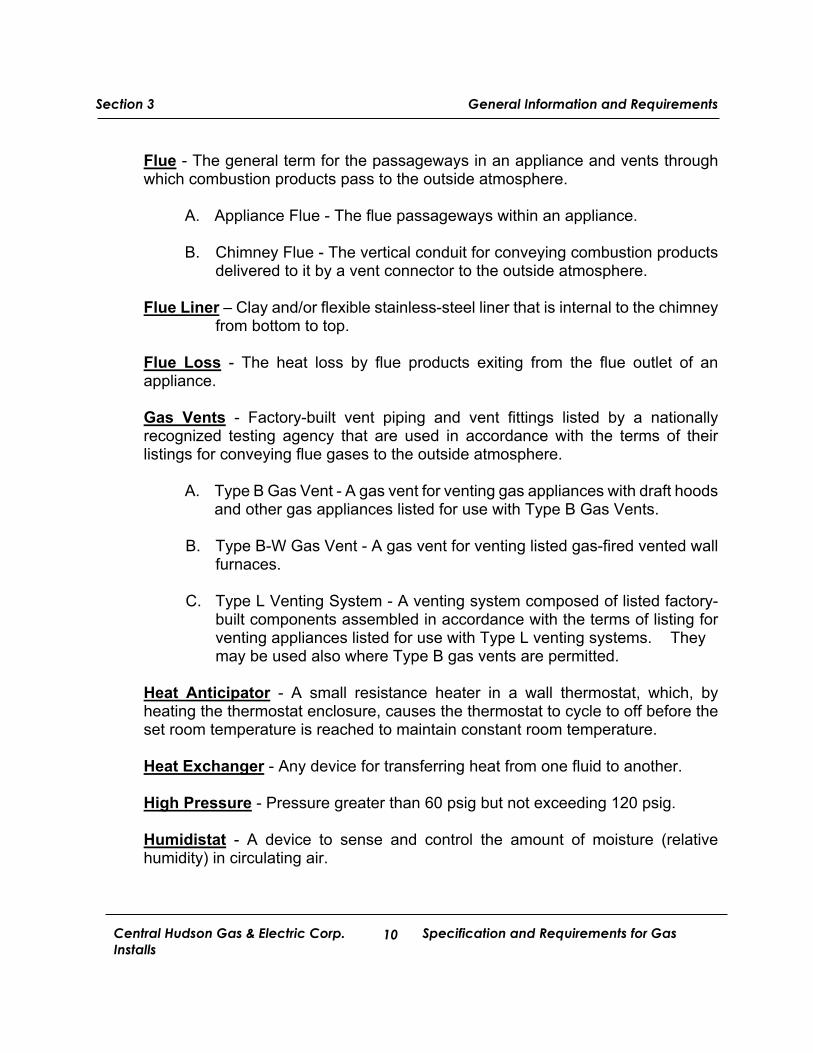
Flue - The general term for the passageways in an appliance and vents through which combustion products pass to the outside atmosphere.
A. Appliance Flue - The flue passageways within an appliance.
B. Chimney Flue - The vertical conduit for conveying combustion products delivered to it by a vent connector to the outside atmosphere.
Flue Liner – Clay and/or flexible stainless-steel liner that is internal to the chimney
from bottom to top. Flue Loss - The heat loss by flue products exiting from the flue outlet of an appliance. Gas Vents - Factory-built vent piping and vent fittings listed by a nationally recognized testing agency that are used in accordance with the terms of their listings for conveying flue gases to the outside atmosphere.
A. Type B Gas Vent - A gas vent for venting gas appliances with draft hoods and other gas appliances listed for use with Type B Gas Vents.
B. Type B-W Gas Vent - A gas vent for venting listed gas-fired vented wall
furnaces. C. Type L Venting System - A venting system composed of listed factory-
built components assembled in accordance with the terms of listing for venting appliances listed for use with Type L venting systems. They may be used also where Type B gas vents are permitted.
Heat Anticipator - A small resistance heater in a wall thermostat, which, by heating the thermostat enclosure, causes the thermostat to cycle to off before the set room temperature is reached to maintain constant room temperature. Heat Exchanger - Any device for transferring heat from one fluid to another. High Pressure - Pressure greater than 60 psig but not exceeding 120 psig. Humidistat - A device to sense and control the amount of moisture (relative humidity) in circulating air.
Section 3 General Information and Requirements
Central Hudson Gas & Electric Corp. Specification and Requirements for Gas Installs
11
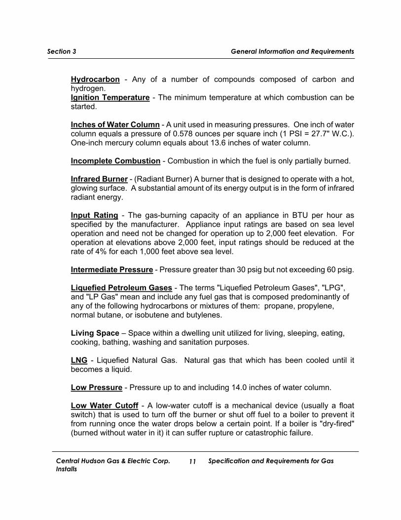
Hydrocarbon - Any of a number of compounds composed of carbon and hydrogen. Ignition Temperature - The minimum temperature at which combustion can be started. Inches of Water Column - A unit used in measuring pressures. One inch of water column equals a pressure of 0.578 ounces per square inch (1 PSI = 27.7" W.C.). One-inch mercury column equals about 13.6 inches of water column. Incomplete Combustion - Combustion in which the fuel is only partially burned. Infrared Burner - (Radiant Burner) A burner that is designed to operate with a hot, glowing surface. A substantial amount of its energy output is in the form of infrared radiant energy. Input Rating - The gas-burning capacity of an appliance in BTU per hour as specified by the manufacturer. Appliance input ratings are based on sea level operation and need not be changed for operation up to 2,000 feet elevation. For operation at elevations above 2,000 feet, input ratings should be reduced at the rate of 4% for each 1,000 feet above sea level. Intermediate Pressure - Pressure greater than 30 psig but not exceeding 60 psig. Liquefied Petroleum Gases - The terms "Liquefied Petroleum Gases", "LPG", and "LP Gas" mean and include any fuel gas that is composed predominantly of any of the following hydrocarbons or mixtures of them: propane, propylene, normal butane, or isobutene and butylenes. Living Space – Space within a dwelling unit utilized for living, sleeping, eating, cooking, bathing, washing and sanitation purposes. LNG - Liquefied Natural Gas. Natural gas that which has been cooled until it becomes a liquid.
Low Pressure - Pressure up to and including 14.0 inches of water column. Low Water Cutoff - A low-water cutoff is a mechanical device (usually a float switch) that is used to turn off the burner or shut off fuel to a boiler to prevent it from running once the water drops below a certain point. If a boiler is "dry-fired" (burned without water in it) it can suffer rupture or catastrophic failure.
Section 3 General Information and Requirements
Central Hudson Gas & Electric Corp. Specification and Requirements for Gas Installs
12
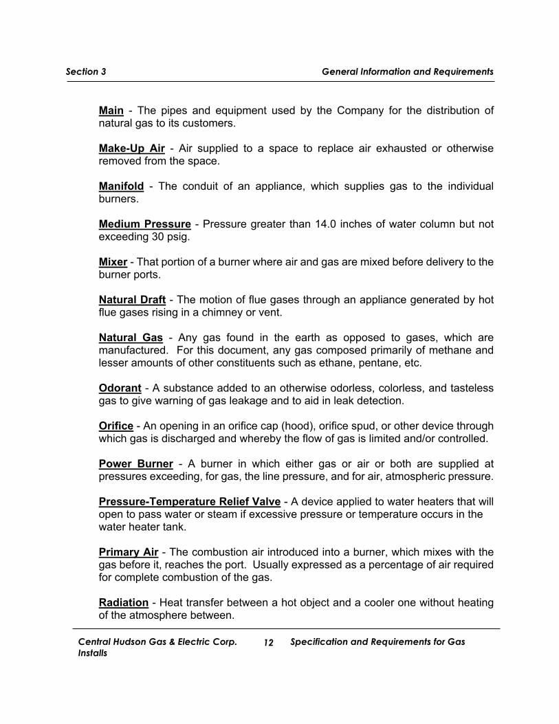
Main - The pipes and equipment used by the Company for the distribution of natural gas to its customers. Make-Up Air - Air supplied to a space to replace air exhausted or otherwise removed from the space. Manifold - The conduit of an appliance, which supplies gas to the individual burners. Medium Pressure - Pressure greater than 14.0 inches of water column but not exceeding 30 psig. Mixer - That portion of a burner where air and gas are mixed before delivery to the burner ports. Natural Draft - The motion of flue gases through an appliance generated by hot flue gases rising in a chimney or vent. Natural Gas - Any gas found in the earth as opposed to gases, which are manufactured. For this document, any gas composed primarily of methane and lesser amounts of other constituents such as ethane, pentane, etc. Odorant - A substance added to an otherwise odorless, colorless, and tasteless gas to give warning of gas leakage and to aid in leak detection. Orifice - An opening in an orifice cap (hood), orifice spud, or other device through which gas is discharged and whereby the flow of gas is limited and/or controlled. Power Burner - A burner in which either gas or air or both are supplied at pressures exceeding, for gas, the line pressure, and for air, atmospheric pressure. Pressure-Temperature Relief Valve - A device applied to water heaters that will open to pass water or steam if excessive pressure or temperature occurs in the water heater tank. Primary Air - The combustion air introduced into a burner, which mixes with the gas before it, reaches the port. Usually expressed as a percentage of air required for complete combustion of the gas. Radiation - Heat transfer between a hot object and a cooler one without heating of the atmosphere between.
Section 3 General Information and Requirements
Central Hudson Gas & Electric Corp. Specification and Requirements for Gas Installs
13
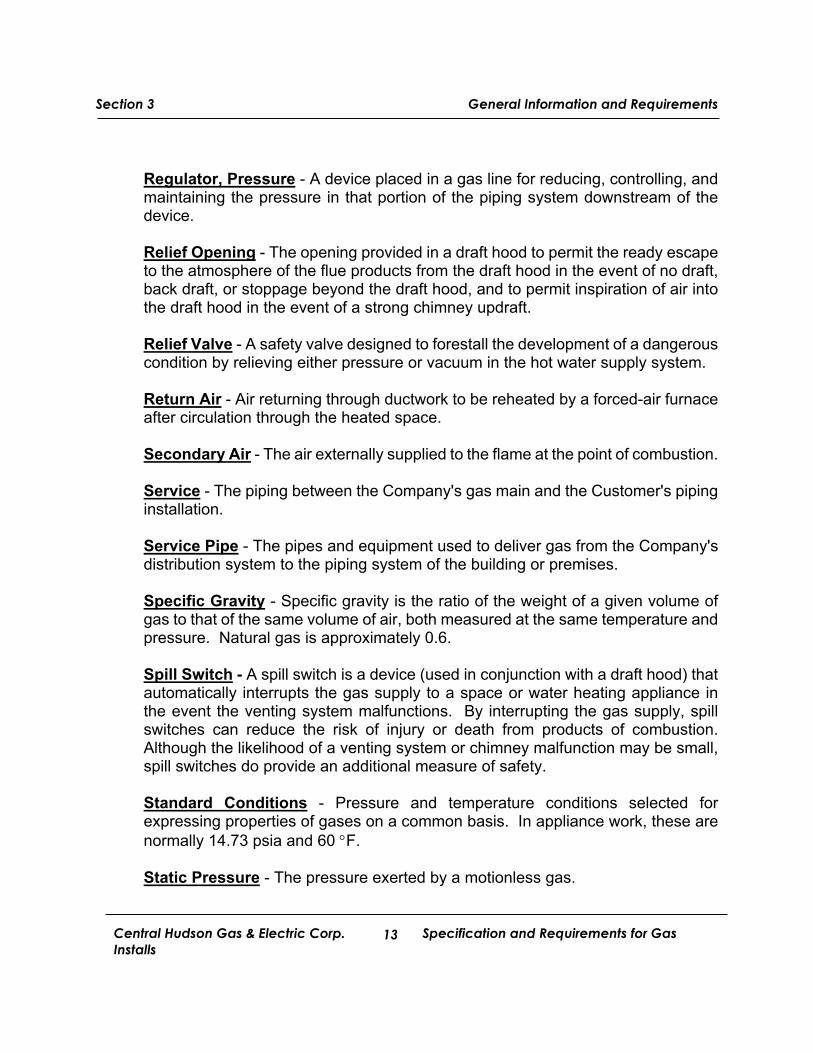
Regulator, Pressure - A device placed in a gas line for reducing, controlling, and maintaining the pressure in that portion of the piping system downstream of the device. Relief Opening - The opening provided in a draft hood to permit the ready escape to the atmosphere of the flue products from the draft hood in the event of no draft, back draft, or stoppage beyond the draft hood, and to permit inspiration of air into the draft hood in the event of a strong chimney updraft. Relief Valve - A safety valve designed to forestall the development of a dangerous condition by relieving either pressure or vacuum in the hot water supply system. Return Air - Air returning through ductwork to be reheated by a forced-air furnace after circulation through the heated space. Secondary Air - The air externally supplied to the flame at the point of combustion. Service - The piping between the Company's gas main and the Customer's piping installation. Service Pipe - The pipes and equipment used to deliver gas from the Company's distribution system to the piping system of the building or premises. Specific Gravity - Specific gravity is the ratio of the weight of a given volume of gas to that of the same volume of air, both measured at the same temperature and pressure. Natural gas is approximately 0.6. Spill Switch - A spill switch is a device (used in conjunction with a draft hood) that automatically interrupts the gas supply to a space or water heating appliance in the event the venting system malfunctions. By interrupting the gas supply, spill switches can reduce the risk of injury or death from products of combustion. Although the likelihood of a venting system or chimney malfunction may be small, spill switches do provide an additional measure of safety. Standard Conditions - Pressure and temperature conditions selected for expressing properties of gases on a common basis. In appliance work, these are normally 14.73 psia and 60 F. Static Pressure - The pressure exerted by a motionless gas.
Section 3 General Information and Requirements
Central Hudson Gas & Electric Corp. Specification and Requirements for Gas Installs
14
Temporary Service - A nonrecurring service intended to be used for a short time only. Therm - A unit of heat energy equal to 100,000 BTU's. Thermocouple - A device consisting of two wires or strips of dissimilar materials, which are joined together at one end (hot junction). When this hot junction is heated, the thermocouple produces a DC voltage across the other two ends (cold junction). Thermostat - A switching device that is temperature-operated to control operation of an appliance. Transmission Pressure - Pressure greater than 125 psig. Unvented Room Heater – An unvented heating appliance designed for stationary installation and utilized to provide comfort heating. Such appliances provide radiant heat or convection heat by gravity or fan circulation directly from the heater and do not utilize ducts. A wall-mounted unvented room heater does not incorporate concealed venting arrangements in its construction and discharges all products of combustion through the front into the room being heated. Upstream - In the direction of the gas supply point. Vent - A device, such as a pipe, to transmit flue products from an appliance to the outdoors. This term also is used to designate a small hole or opening for the escape of a fluid (such as in a gas control). Vent Connector - That portion of the venting system, which connects the gas appliance to the gas vent chimney. Vent Terminal (Vent Cap) - The fitting at the end of a vent pipe that directs the flue gases into the outside atmosphere and keeps out rain, snow, debris, and animals.
Section 3 General Information and Requirements
Central Hudson Gas & Electric Corp. Specification and Requirements for Gas Installs
15
3. GENERAL INFORMATION AND REQUIREMENTS
3.1 Application for Natural Gas Service
3.1.1 Accepted Format
Application for new natural gas service or upgrades to existing service can be made at the Central Hudson website at:
https://www.cenhud.com/forms/gas-service-agreement/ Application may also be made by fax or mail by completing the
Natural Gas Service Request Form in Appendix B. 3.1.2 Required Lead-Time
Application for new service or service upgrade should be made as far as possible in advance of the date gas service is required. Additional lead-time may be necessary to gain additional third-party approvals such as permits or rights-of-way.
3.2 Payment of Fees and/or Deposits
If the Company has been contracted to perform work on Customer property or if previously billed amounts are outstanding, a security deposit or payment arrangements may be required as a condition for service.
3.3 Access In accepting service, the Customer grants to identified Company
employees and its’ agents the right of access to Customer's premises at all reasonable times for such purposes as the reading of meters, inspection of Company meters and or piping. Additionally, upon accepting service, the customer agrees to provide access for installing, operating, maintaining, disconnecting and removing any and all property belonging to the Company whenever necessary into the future. Company employees or their
Section 3 General Information and Requirements
Central Hudson Gas & Electric Corp. Specification and Requirements for Gas Installs
16
contractors authorized to visit Customer premises are furnished with an identification card, which they will show upon request. The Company reserves the right to disconnect service, should access for required maintenance and gas safety inspections of company owned equipment is repeatedly denied.
3.4 Character of Natural Gas Service
3.4.1 Responsibility
The Company will designate the character of service, meter location and the point of attachment.
3.4.2 Natural Gas Characteristics
Natural gas having a monthly average heating value of not less than 1,000
BTU per cubic foot is supplied to the Customer. Normal delivery pressure is 7 inches water column. However, seasonal variations from 4 to 12 inches water column may occur.
Large commercial or industrial loads may be supplied at higher pressures upon application to and approval by the Company.
3.5 New Natural Gas Service or Construction
3.5.1 Installation Requirements
A service will not be energized until all vented gas appliances, and all other appliances that are present at the time of unlock, are installed and operational.
3.6 Temporary Service
3.6.1 General
The Company provides temporary gas service for construction purposes, non-permanent usage, or other non-recurring uses.
Section 3 General Information and Requirements
Central Hudson Gas & Electric Corp. Specification and Requirements for Gas Installs
17
3.6.2 Installation Requirements
The Customer shall provide substantial and adequate support for temporary service. The temporary service piping and equipment shall be installed and inspected in the same manner as required for permanent installations. Appliances requiring venting as per Fuel Gas Code of New York State must have code compliant venting fully installed before turn-on. Furthermore, temporary service installations will abide by all other regulations that apply in the Fuel Gas Code of New York State (latest edition).
3.6.3 Cost The entire cost of installing and removing the temporary service facilities is the responsibility of the Customer.
3.7 Excavation, Construction and Demolition near Company Underground Facilities
3.7.1 General
Excavation, construction, and demolition at or near underground facilities require strict adherence to the provisions of 12 NYCRR 753 (Code Rule 753). The Customer/Contractor must call 811 several days in advance of such activities. 3.7.2 Responsibility
It is the responsibility of the Customer/Contractor to contact DigSafely New York by dialing toll free ‘811’ to request a markout of all below grade facilities (electric, natural gas, telephone, water, sewer, etc.) shall be made at least two (2) but not more than ten (10) working days prior to the start of the proposed work. While many municipalities (water, sewer, etc.) are members of DigSafely New York, not all are. Therefore, a separate notification must be made to the municipality in these cases. If the excavation work will take place in the vicinity of privately-owned underground facilities it is the responsibility of the excavator to notify the facility owner.
Section 3 General Information and Requirements
Central Hudson Gas & Electric Corp. Specification and Requirements for Gas Installs
18
At least seven working days in advance of the commencement date of the demolition, the excavator shall request an on-site Pre-Demolition Conference, through the one call notification system with all operators who have underground facilities at or near the proposed demolition area. A request for a Pre-Demolition Conference is not a substitute for the notice of intent to perform demolition work required by Code Rule 753.
The Customer/Contractor shall preserve and protect locational
markings of Company underground facilities. The Customer/Contractor shall provide satisfactory protection of the Company's underground facilities in accordance with the provisions of Code Rule 753.
3.8 Work Authorization
The Company prohibits any work on its facilities by unauthorized personnel. This includes, service risers, regulators, regulator stations, meters, meter bars and manifolds, etc.
Exception: Customer piping tie-in connection to Company Installed and Approved meter set or meter manifold position.
Section 4 Service Pipe Installations
Central Hudson Gas & Electric Corp. Specification and Requirements for Gas Installs
19
4. SERVICE PIPE INSTALLATIONS
4.1 General
4.1.1 Service Pipe
The Company will typically size and provide gas service to each building or premise through a single service pipe except where, for economic, operational, or load considerations, the Company elects to install more than one service pipe. The required service piping will be based on customer provided load information.
4.1.2 Route of Service
The route of the service and the type of construction will be determined by the Company after taking into consideration the location, size and nature of the proposed load and its relation to Company facilities.
4.1.3 Point of Service Termination
The Company's service pipe shall terminate at the outlet piping of the Company's meter or at the gas pressure regulator supplying the Customer's piping. The Company reserves the right to specify the location of the gas service connection. The Customer shall consult with the Company regarding the location of the service connection prior to starting construction. The Customer will pipe to the Company’s meter set location. 4.1.4 Easements and Rights-of-Way
Easements or rights-of-way may be required, at Customer expense,
to give the Company access to the metering/service installation and equipment for the purpose of connecting/energizing the service and for other purposes necessary for the delivery of service.
Section 4 Service Pipe Installations
Central Hudson Gas & Electric Corp. Specification and Requirements for Gas Installs
20
4.2 Customer Piping
4.2.1 General
All customer owned natural gas installations, including piping, valves and fittings, shall meet all applicable code requirements including but not limited to the Fuel Gas Code in New York State (latest edition), this document and any other applicable local or municipal requirements. Customer piping must be installed plumb and level. In addition, it shall be properly supported to minimize any resulting stress or strain to the Company meter installation. Piping installed above ground outdoors shall be protected from atmospheric corrosion by appropriate coating or paint, securely supported and located where it will be protected from physical damage. Where passing through an outside wall, the piping shall also be protected against corrosion by coating or wrapping with an approved inert material. Where piping is encased in a protective pipe sleeve, the annular space between the piping and the sleeve shall be sealed.
Gas piping installed on the roof surfaces shall be elevated above the roof surface and shall be supported in accordance with the National Fuel Code section 7.2.5.4 and Table 7.2.5.2. The support interval required for rooftop piping installations is the same as the support intervals required for all indoor piping. Rooftop gas piping runs for new construction on slightly sloped commercial roofs, must be installed in the direction of slope to prevent pipe breakage during ice sheet and snow sheet runoff. Rooftop installations are increasingly used for large retail / commercial buildings, and other applications. Note that the requirement does not specify a height the pipe needs to be elevated above the roof. Depending on local weather conditions and construction practices, the authority having jurisdiction may have specific height requirements for piping installed on rooftops, particularly where snow or rain may accumulate on a flat roof. Roof based supports shall be secured to the roof. Underground piping, where installed below grade through the outer foundation or basement wall of a building, shall terminate on each end with Company approved gas risers. Refer to Figure 10. The annular space
Section 4 Service Pipe Installations
Central Hudson Gas & Electric Corp. Specification and Requirements for Gas Installs
21
between the gas piping and the sleeve shall be sealed and wrapped with an approved material suitable for the application at the foundation or basement wall to prevent entry of gas or water. The Customer/Contractor shall provide a diagram of the installed customer owned underground piping to the District Service Supervisor. Customer piping shall be supplied and maintained by the Customer.
4.2.2 Distribution Piping
Distribution piping in buildings shall be wrought iron, steel, galvanized steel or CSST (Corrugated Stainless-Steel Tubing).
The Customer's distribution piping shall be sized to adequately supply the rated demand of all connected appliances and in accordance with Section 402 of the Fuel Gas Code in New York State (latest edition).
Pipe size shall be calculated to prevent pressure drops greater than the minimum pressure required for proper equipment operation for low-pressure systems (see Section 402 of the Fuel Gas Code of New York State (latest edition)).
In addition, wrought iron, steel and galvanized steel piping shall be no smaller than 3/4" in pipe size for appliances rated at 50,000 Btuh or less and no smaller than 1" in pipe size, to within 18", of appliances rated in excess of 50,000 Btuh. CSST piping shall be no smaller than 23 equivalent hydraulic diameter (EHD) for appliances rated at 50,000 Btuh or less and no smaller than 31 EHD, to within 18", of appliances rated in excess of 50,000 Btuh.
Where the Customer piping is of a size not normally stocked by the Company, the Customer shall supply a suitable adaptor for connection to the Company's piping. For example, if the Customer uses 1½" distribution piping, a reducing fitting must be provided by the Customer to allow connection to the Company's 1" piping.
All runs should be parallel and/or at right angles to joists when practical.
Section 4 Service Pipe Installations
Central Hudson Gas & Electric Corp. Specification and Requirements for Gas Installs
22
Multiple runs of customer piping that terminate at a Company multi meter manifold shall have labels on the piping stating what is served by each customer pipe. Gas metal piping, including CSST piping, shall not be used as a grounding electrode. For CSST bonding, refer to the Fuel Gas Code of New York State Section 310 for requirements.
4.2.3 CSST Piping Installation of CSST piping shall be in accordance with the requirements set forth in the Fuel Gas Code of New York State. The Customer should verify with the local municipality if CSST piping is allowed.
CSST should be installed within the building structure. When installed along the side of a structure in an exposed condition, the CSST shall be protected inside a conduit or chase.
Gas Meter Connections: CSST systems shall terminate at the exterior wall of the building with a listed termination fitting securely mounted to the exterior of the structure. The termination fitting shall be rigidly connected to the gas meter with approved steel piping material. An acceptable alternate design is to penetrate the exterior wall with steel pipe and provide a rigid attachment for CSST within the building.
Installation of piping shall be performed only by service personnel specifically trained by CSST manufacturers and approved manufacturer representatives. Proof of CSST licensing shall be provided upon request. Installation of CSST components shall be in accordance with standard practices set forth by the manufacturer. Striker plates shall be utilized wherever a tubing puncture threat may exist. Minimum bending radius of CSST shall conform to manufacturers recommended minimum bend radius.
Shut off valves installed in tubing systems shall be rigidly and
securely supported independently of the tubing. Testing of CSST piping shall be performed on entire system and not
just the manifold (see also Section 4.5).
4.2.4 Press-Connect Fittings
May be utilized in accordance with the requirements set forth in the Fuel Gas Code of New York State (latest version). Use of press connect fittings is also authorized by NFPA 54 2018 Table A.5.6, and ANSI LC-4/CSA 6.32. Installers must be trained by the manufacturer or approved manufacturer’s representative. All press fittings utilized regardless of manufacturer must comply with ANSI 6.32 installation requirements.
4.3 Relocation of Existing Company Facilities
Any relocation of existing Company facilities requested by the Customer, including the point of service termination, the location of the service piping, meters, or regulators, will be made in accordance with the Company's current relocation policy. The Customer will be responsible for reimbursing the Company for the requested work. See Appendix E for listing of charges for gas related work on Customer property.
4.4 URD Subdivisions
4.4.1 General New York State Public Service Codes, Rules and Regulations
require underground residential distribution (URD) in all new subdivisions, or in a new section of an existing subdivision, consisting of five (5) or more single-family homes or one or more multiple occupancy dwellings (including four (4) or more dwelling units). All mobile home developments, or extensions of an existing development, with five (5) or more permanent sites shall also be provided with a URD system. Information on URD and related costs can be obtained by contacting the Company.
4.4.2 Application Requirements
Prior to construction by the Company, the applicant for construction
of underground electric and natural gas lines in a residential subdivision shall:
Submit an application to the Company with sufficient lead-
time for design of the facilities within the development.
Provide the Company with a site map in AutoCAD DWG format approved by the local authority. The map shall show
Section 4 Service Pipe Installations
Central Hudson Gas & Electric Corp. Specification and Requirements for Gas Installs
24
the location of all lot lines, roads, sidewalks, curbs, water lines, sewer lines, storm drains and grades.
Install all other proposed underground facilities including water mains, sewer lines, and drainage facilities.
Establish final roadway and parking area grades within six (6)
inches of final grade; place and maintain construction survey stakes indicating grades, property lines and the location of other utilities. Curbs shall be installed before the underground facilities are installed.
Make such contribution and/or deposit as may be required in accordance with Company tariffs.
4.4.3 Additional Requirements
Services shall not be energized unless the following requirements are met: The installation is made in accordance with the requirements
as contained herein. The installation meets all applicable codes and standards. The service lateral conductors shall be backfilled with proper
sand padding for the entire length of the trench. The trench must be open for inspection by the authority having jurisdiction before backfilling. If the service fails to meet approval, the service must be corrected and inspected by the authority having jurisdiction.
Yellow insulated copper Tracer Wire shall be installed adjacent
to the underground nonmetallic piping. Access shall be provided to the tracer wire or the tracer wire shall terminate above ground at each end of the nonmetallic piping. Tracer wire shall not be less than 18 AWG and the insulation type shall be suitable for direct burial.
Section 4 Service Pipe Installations
Central Hudson Gas & Electric Corp. Specification and Requirements for Gas Installs
25
After approval by the authority having jurisdiction, the service lateral conductors shall be backfilled prior to the Company energizing service.
Backfill shall be consistent with Construction Standard G 01 03 005.0 in the Appendices.
4.5 Pressure Testing
Prior to acceptance and initial operation, every natural gas piping installation shall be inspected, and pressure tested to determine that the materials, design, fabrication, and installation practices comply with the requirements of Section 406 of the Fuel Gas Code of New York State (latest edition)
Test pressure shall be measured with a manometer or with a pressure-
measuring device designed and calibrated to read, record, or indicate a pressure loss due to leakage during the pressure test period. The source of pressure shall be isolated before the pressure tests are made.
The test pressure to be used shall be no less than 1-1/2 times the
proposed maximum working pressure, but not less than 3 psig (20 kPa gauge), irrespective of design pressure. Where the test pressure exceeds 125 psig (862 kPa gauge), the test pressure shall not exceed a value that produces a hoop stress in the piping greater than 50% of the specified minimum yield strength of the pipe.
The contractor shall perform the test in the presence of a Company
Commercial Representative or, with prior approval, provide a written letter indicating that the test was performed and that the piping system passed that test. (See Gas Piping Pressure and Leakage Test Form in Appendix A.) The duration of the test shall be enough to determine if a leak is present. In no case shall the length be less than 15 minutes for residential applications. Consult the Fuel Gas Code of New York State (latest edition) for commercial applications.
Pressure Test Form Link
https://www.cenhud.com/forms/gas-piping-pressure-and-leakage-test-form/
Section 4 Service Pipe Installations
Central Hudson Gas & Electric Corp. Specification and Requirements for Gas Installs
26
This page was intentionally left blank.
Central Hudson Gas & Electric Corp.
Section 4 Service Pipe Installations
Central Hudson Gas & Electric Corp. Specification and Requirements for Gas Installs
27
5. METERING
5.1 General
The Company will furnish, install, and connect all meters required for billing purposes, and reserves the right to designate and approve all meter locations. The Company will provide and install a meter bar or equivalent mounting facilities and will connect its supply piping to the inlet connection of the meter bar. For single-meter residential services, the Customer or contractor shall connect the building’s piping to the outlet connection of the meter bar. For all other types of service, the Company, at its discretion, will connect the building’s piping to the outlet of the Company’s meter set piping. Whenever it is necessary to know in advance the dimensions of the meter to be used on a installation, the Company shall be consulted before the piping installation is started.
5.2 Meter Location Meters shall be located outdoors. The Customer shall bring his piping to the
outside of the building wall adjacent to the meter location. For mobile home installations, the Company will supply a flexible hose connection between the outlet of the meter and the Customer's piping connection.
It is in the mutual interest of both the Customer and the Company to provide
a suitable outside meter location to facilitate examination, reading, billing, and replacement. Such location is to be as near as practicable to the point where the gas supply piping enters the building.
Gas meters shall not be installed where they will be subject to damage such
as in driveways, public passages, show windows, under porches, or over doors, showcases, or shelving, or close to machinery, or in similar inconvenient or dangerous locations, or where they will be exposed to excessive corrosion. Where no such location is available, the Customer shall provide adequate protection for the Company's meter. Such protection shall meet or exceed the Company's standards and requirements.
Section 4 Service Pipe Installations
Central Hudson Gas & Electric Corp. Specification and Requirements for Gas Installs
28
A clear working space of four feet square shall be provided and maintained in front of the gas meter by the Customer. This space shall be permanently free of all obstructions, including but not limited to shrubs, bushes, trees, or other large plantings that may impede this required clear four foot/sq. working space. Separation between a gas meter/regulator and an electric meter and/or meters shall be three (3) feet minimum (see Figure 16).
If the meter cannot be located in accordance with any of the above
requirements, the Company shall be consulted before the piping installation is started.
5.3 Multiple Meters
When more than one meter is installed, the contractor installing the Customer's gas piping shall plainly mark each meter connection with a metal tag or other permanent means, designating the part of the building supplied through that meter.
When three or more meters are to be installed at one location, the Customer
shall consult the Company before starting the piping installations since such installations require special consideration.
5.4 Customer Service Valve
This valve shall be placed inside the building near the point where the Customer's piping enters and shall be so located and installed that it will be accessible for operation (see Figure 1). If two or more meters supply the building, each meter supply valve shall be clearly marked to show the portion of the building gas piping system it controls. For those situations where the inside installation of a control valve would be impossible or inaccessible, the valve may be installed outside of the building providing prior Company approval is obtained.
Section 4 Service Pipe Installations
Central Hudson Gas & Electric Corp. Specification and Requirements for Gas Installs
29
5.5 Unauthorized Use
The breaking of seals, tampering with meters and unmetered piping is strictly prohibited (New York State Penal Law, Section 165.15). Violators will be prosecuted.
5.6 Demolition
The Company requires a minimum of seven (7) working days prior to starting demolition. No building demolition shall be undertaken until the Company's meters and regulators have been removed and the gas service has been retired (see also Section 3.7). It is the Customer’s responsibility to call 811 and schedule a pre-demolition meeting to consult with the local municipality, utilities, and other involved parties prior to commencing demolition work. See Section 3.7.
Section 4 Service Pipe Installations
Central Hudson Gas & Electric Corp. Specification and Requirements for Gas Installs
30
This page was intentionally left blank.
Central Hudson Gas & Electric Corp.
Section 6 Adequacy and Safety of Installation
Central Hudson Gas & Electric Corp. Specification and Requirements for Gas Installs
31
6. ADEQUACY AND SAFETY OF INSTALLATION
6.1 General
The Company reserves the right to withhold service or discontinue service whenever the Customer's piping or equipment is found to be unsafe, inadequate, or unsuitable for receiving the Company's service. Service to a Customer may also be discontinued if it is determined to interfere with or impair the quality or continuity of service to the Customer or others. The Company has a "warning tag" procedure to cover hazardous conditions found on Customer premises. It is the Customer's responsibility to correct such deficiencies before service will be restored.
6.2 Liability
The Company, either by inspection or non-rejection, does not give any warranty as to the adequacy, safety, or other characteristics of any structure, equipment, piping, or appliances owned, installed, or maintained by the Customer or leased by the Customer from a third party.
6.3 Gas Odors
The Customer shall immediately notify the Company of any suspected gas odor, leakage or escape of gas by calling our toll-free hotline 1-800-942-8274 (note: this number is for reporting gas odors only) or 9-1-1.
6.4 Customer’s Installation
The Customer's piping, equipment, and appliances must be safe, adequate, and in accordance with generally accepted practice and applicable codes.
Before the gas unlock appointment commences, the Customer’s appliances
must be fully wired and the water operational to appliances that utilize water before the gas meter will be turned on.
Section 6 Adequacy and Safety of Installation
Central Hudson Gas & Electric Corp. Specification and Requirements for Gas Installs
32
This page was intentionally left blank.
Central Hudson Gas & Electric Corp.
Section 7 Appliance Installation
Central Hudson Gas & Electric Corp. Specification and Requirements for Gas Installs
33
7. APPLIANCE INSTALLATION
7.1 Certification
Gas appliances and accessories shall comply with applicable ANSI requirements regarding safe operation, substantial and durable construction, and acceptable performance (See also Chapter 6 of the Fuel Gas Code of New York State).
Such compliance may be determined by the presence on the appliance or
accessory of a label of a nationally recognized testing agency such as the Canadian Standards Association (CSA). Compliance may also be determined by the listing of the appliance or accessory in a list published by such a nationally recognized testing agency that certifies the appliance or accessory complies with national safety requirements.
If no applicable ANSI requirements or certification listing exists for a
particular appliance or accessory, specific approval of the Company shall be obtained prior to installation.
7.2 Installation and Accessibility
The appliance installation shall be made in accordance with the Fuel Gas Code of New York State and any other applicable codes or regulations.
All accessibility requirements as listed I Section 306 of the Fuel Gas Code of
NYS shall be followed.
7.3 Equipment Shut-off Valves and Connections
Any gas utilization equipment connected to a piping system shall have an accessible, approved manual shut-off valve located on the same level (floor) installed upstream of any connector and within six (6) feet of the equipment it serves. A union or flanged connection shall be provided downstream from this valve to permit removal of controls. All installations are to be in compliance with the Fuel Gas Code of New York State (latest edition). All valves must be approved for use with gas fuel systems. One half-inch (1/2") valves are limited to the full port, ball type only. The use of core valves is limited to 3/4" and above. Shut off
Section 7 Appliance Installation
Central Hudson Gas & Electric Corp. Specification and Requirements for Gas Installs
34
valves shall be provided with access. Shut off valves serving movable appliances, such as cooking appliances and clothes dryers, shall be considered to be provided with access where installed behind such appliances. Appliance shutoff valves located in the firebox of a fireplace shall be installed in accordance with the appliance manufacturer’s instructions.
All steam and hot water boilers shall be protected with a low-water fuel cutoff control in accordance with Section 1007 of the Mechanical Code of New York State (see also Section 7.4.1).
Any reduction in pipe size for appliance connection must be made downstream of the appliance shut-off valve and within a maximum of 18" of the appliance being connected.
Approved flexible connectors will be permitted for ranges and dryers. All
other gas utilization equipment must be hard piped with the exception of approved equipment using manufacturer supplied flexible connectors or equipment requiring flexible connections to satisfy the manufacturer's installation instructions.
The installation of flexible connectors must satisfy the provisions of the Fuel
Gas Code of New York State (latest edition). In particular:
Flexible connectors must be of minimum practical length.
Flexible connectors must be visible and entirely within the same room as the equipment being served.
Flexible connectors must be protected from corrosion as well as
physical, thermal damage.
An accessible shut-off valve must be provided in the rigid piping immediately upstream from the flexible connection or quick disconnect device.
Appliances that are moved should have a new flexible connector
installed at the time of appliance reinstallation.
Section 7 Appliance Installation
Central Hudson Gas & Electric Corp. Specification and Requirements for Gas Installs
35
7.4 Specific Appliances
7.4.1 Boilers
All steam and hot water boilers shall be protected with a low-water cutoff control (see also Section 1007 of the Mechanical Code of New York State).
The low-water cutoff shall automatically stop the combustion
operation of the appliance when the water level drops below the lowest safe water level as established by the manufacturer.
7.4.2 Unvented Gas Space Heaters
The Fuel Gas Code of New York State (latest edition) permits the sale and installation of unvented gas space heaters as supplemental heat sources in residential applications up to 40,000 BTU. The Company will allow the installation of these units if they comply with applicable state and municipal codes. 7.4.3 Air Conditioners
Gas piping serving gas heating utilization equipment may also serve cooling equipment when heating and cooling equipment cannot be operated simultaneously (see Section 626 of the Fuel Gas Code of New York State (latest edition)).
7.4.4 Domestic Water Heaters
Domestic water heaters shall be located as close as practicable to the
chimney or gas vent and shall be effectively vented. These appliances, with the exception of those having sealed combustion systems, shall not be installed in bathrooms, bedrooms, or any occupied rooms normally kept closed (see Section 502 of the Plumbing Code of New York State).
Section 7 Appliance Installation
Central Hudson Gas & Electric Corp. Specification and Requirements for Gas Installs
36
7.4.5 Pool Heaters
Pool and Spa Heaters shall be tested in accordance with ANSI Z21.56 and shall be installed in accordance with the manufacturer’s installation instructions. If the pool heater is supplied with natural gas from meter set and customer owned piping is installed underground the piping shall be plastic high-density polyethylene, which meets ASTM standard D2513. The pipe shall be rated for 100 PSIG. Each end of the customer owned underground gas piping to the pool shall have an approved riser. (Refer to figure #10). Tracer wire and danger tape is also required to be installed in trench. (Refer to figure #16). A sketch of the customer underground gas piping installation including measurements to its location shall be provided to Central Hudson. In most cases a larger capacity gas meter will be required to supply the additional load of the pool heater. It is the customer’s and or their contractor’s responsibility to contact Central Hudson at least 2-weeks before the larger meter installation is required. 7.4.6 Generators
Customer or Contractor must contact Central Hudson before the purchase of a natural gas generator to confirm gas system pressure capabilities in your area and your existing service capacity can handle the natural gas input requirements. (You need to get Generator BTU Load value before contacting the Central Hudson) It is the customer’s and or their contractor’s responsibility to contact the gas company at least 2-weeks before the larger meter installation is required.
7.4.7 ON-Demand Water Heaters
Contact Central Hudson before purchase an On-Demand Water Heater to confirm your present gas service size can handle the increased on-demand load. (You need to get On-Demand Water Heater BTU Load value before contacting the Central Hudson) It is the customer’s and or their contractor’s responsibility to contact the gas company at least 2-weeks before the larger meter installation is required.
Section 7 Appliance Installation
Central Hudson Gas & Electric Corp. Specification and Requirements for Gas Installs
37
7.4.8 Conversion Burners
Conversion Burners must be installed as per manufacturer’s instructions. You must have a cleaned and lined chimney. You must have all required safety devices installed. (i.e.: spill switch, low water cutoff. Gas damper must be installed in place of a barometric damper.) Firing rate should not be set to lower than 10% of appliance input rating or no greater than 5% above input rating.
7.4.9 Specialized Process Equipment
The customer or customer’s contractor must contact the gas company if any of the gas utilization equipment to be installed requires pressure beyond 8” of W.C. for proper operation.
Section 8 Venting, Chimneys, and Combustion Air
Central Hudson Gas & Electric Corp. Specification and Requirements for Gas Installs
38
8. VENTING, CHIMNEYS, AND COMBUSTION AIR
8.1 General Venting systems shall be designed and constructed so as to provide a
positive flow adequate to remove flue gases to the outside atmosphere (see Chapter 5 of the Fuel Gas Code of New York State).
A venting system serving gas utilization equipment requiring draft for proper
operation shall be designed and installed to develop adequate draft. The installation shall satisfy the draft requirements of the equipment as defined in the manufacturer's instructions.
Appliances should be installed as close as possible to the vent.
The flue should enter the vent as high as possible while
maintaining proper clearances.
Where multiple appliances utilize a common vent, install the smaller input appliance closer to the vent or provide a separate entrance higher in the vent for the smaller appliance.
Multistory venting shall be in accordance with Section 504 of the
Fuel Gas Code of New York State.
Equipment burning solid fuel shall not be connected to gas vents.
8.2 Venting Systems and Spill Switch Requirements
It is the Customer's responsibility to ensure chimneys and vents are inspected to ascertain that they are clear and free of obstructions.
It is required that masonry chimneys that are not clay lined, be lined with
suitable listed stainless-steel flue liners. Aluminum liners are not permitted in Central Hudson Service Territory.
A complete cleaning and documented inspection of a clay lined chimney flue is required before turn-on when converting from other fuels to natural gas.
Section 8 Venting, Chimneys, and Combustion Air
Central Hudson Gas & Electric Corp. Specification and Requirements for Gas Installs
39
It is required that a sleeve be used for the flue connection to a chimney. This sleeve should be set using masonry cement and should be located at least 4" above the base of the chimney flue.
Sizing and termination of vents shall be as described in the Fuel Gas Code of New York State (latest edition).
The use of a spill switch is required in the following instances:
Whenever a new space or water heating appliance is installed with an atmospheric draft hood that does not have an automatic safety device that interrupts the gas supply in the event of a venting system malfunction.
Whenever an existing space or water heating appliance is converted
from some other fuel to natural gas.
***whenever a spill switch is found to not be present or in working order on an existing space or water heating appliance with an atmospheric draft hood during any Gas Odor or C.O. Emergency investigation and, or during routine gas maintenance work.
For existing space and water heating appliances, it is strongly encouraged that spill switches be retrofitted.
Note: A spill switch is a device (used in conjunction with a draft hood) that automatically interrupts the gas supply to a space or water heating appliance in the event the venting system malfunctions. By interrupting the gas supply, spill switches can reduce the risk of injury or death from products of combustion. Although the likelihood of a venting system or chimney malfunction may be small, spill switches do provide an additional measure of safety.
Wherever a chimney is used with a fuel gas appliance, an accessible
cleanout shall be provided. The cleanout shall have a tight-fitting cover and be installed so its upper edge is at least twelve (12) inches below the lower edge of the lowest chimney inlet opening.
Section 8 Venting, Chimneys, and Combustion Air
Central Hudson Gas & Electric Corp. Specification and Requirements for Gas Installs
40
8.3 Natural Gas Regulators 8.3.1 Regulators
Regulators shall not be located directly underneath windows or other
building openings. 8.3.2 Regulator Venting
All regulators shall be vented in accordance with Section 410 of the Fuel Gas Code of New York State and the following:
All vent lines must be sized at least the size of the vent tap in the
regulator. At no time in the piping scheme shall the inside diameter be allowed to be decreased below this size.
Vent lines shall be routed to the outside utilizing the most direct practical
route to minimize bends and elbows. Vent terminus shall be located at least eighteen (18) inches from any opening where gas can enter the building.
Minimum vent size (as indicated by vent tap size) may be run a
maximum distance of 25 to 30 feet of equivalent pipe feet without increasing size. Vent size should be increased one pipe size for each additional 25 to 30 feet of pipe run.
Regulators that develop chatter during operation, must have the first 25
to 30 feet of vent pipe removed and increased one pipe size. This should eliminate the chatter.
It is recommended that each regulator be vented separately.
Manifolding of regulator vents should be avoided. If a manifold configuration is proposed, the Customer/contractor shall submit to the Company a release from the regulator manufacturer stating that the design is approved prior to receiving service.
Section 8 Venting, Chimneys, and Combustion Air
Central Hudson Gas & Electric Corp. Specification and Requirements for Gas Installs
41
8.3.3 Combustion Air
All appliances shall be installed in a manner that provides adequate air for combustion. All installations shall be in accordance with the provisions of Section 304 of the Fuel Gas Code of New York State.
*Direct-Vent Appliances, gas appliances of other than natural gas natural
draft design, vented gas appliances not designated as Category 1 and appliances equipped with power burners shall be provided with combustion, ventilation and dilution air in accordance with the appliance manufacturer’s instructions.
Exception: Type 1 clothes dryers that are provided with makeup air in accordance with Section 614.6 of the Fuel Gas Code of NYS.
*Ref.-Fuel Gas Code of NYS Section 304/304.1
Section 9 Customer Installed Low Pressure Underground Service Piping to Outdoor Appliances
Central Hudson Gas & Electric Corp. Specification and Requirements for Gas Installs
42
This page was intentionally left blank.
Central Hudson Gas & Electric Corp.
Section 9 Customer Installed Low Pressure Underground Service Piping to Outdoor Appliances
Central Hudson Gas & Electric Corp. Specification and Requirements for Gas Installs
43
9. CUSTOMER INSTALLED LOW PRESSURE
UNDERGROUND SERVICE PIPING TO OUTDOOR APPLIANCES
9.1 Purpose
This standard has been developed for use by the Customer/Contractor when installing low-pressure underground piping to supply outdoor gas appliances. It will avoid the need for the Company to provide an additional meter (and meter charge) at the Customer’s facility.
This standard is not meant to be a complete summary of the rules and regulations governing the installation of outdoor gas piping. However, compliance with its conditions will help aid in the safe and timely supply of gas service to equipment.
This standard in no way relieves the Customer/Contractor of responsibility for installing gas piping in accordance with the Fuel Gas Code of New York State and all other applicable codes.
This standard will provide the basic information needed to install a gas distribution system. If more information about specific applications regarding safety or installation is required, please contact the Company.
9.2 Installation
The Customer shall install the piping in accordance with Figures 10-13. Any deviation must be discussed with the Company Service Supervisor prior to installation to prevent unnecessary delays. The following rules shall be adhered to for all installations:
The Customer shall provide the Company with an as-built drawing
showing the location of the pipe for future maintenance.
Section 9 Customer Installed Low Pressure Underground Service Piping to Outdoor Appliances
Central Hudson Gas & Electric Corp. Specification and Requirements for Gas Installs
44
Only high-density polyethylene plastic pipe may be used for underground sections of the gas piping service. Joining of underground pipe shall be accomplished by using mechanical compression couplings or electrofusion couplings if qualified to install them.
Allow for expansion and contraction of gas pipe by meandering the pipe
in the trench between the two galvanized steel service risers.
A shutoff valve shall be installed above ground at each end of the gas pipe at each galvanized steel service riser.
The piping system shall be pressure tested prior to back filling (Appendix
A). The test shall be performed at 10 PSIG and shall last for a full 15 minutes after a 15-minute stabilization period.
The minimum depth of cover over the piping shall be 18 inches. Install
a six-inch cushion of sand both above and below the pipe for protection (the minimum trench depth must be 24"). Soil free from rocks and sharp fill may be returned as backfill. The backfilled trench shall be crowned to allow for future settlement. It is in the Customer’s best interest to locate the service run where it will most likely not encounter future disturbances from external forces (see Figure 13).
All service lines shall be installed with clearance of not less than 12”,
whenever practical from any subsurface structures not associated with the pipeline. When 12” is not practical, a minimum clearance of 4” shall be maintained and the pipeline protected from damage as detailed in the Appendices Figure 19.
It is required that a #12 AWG insulated tracer wire be installed at the
same depth as or just below the plastic pipe but not in contact with it. Both ends of the wire run shall be wrapped around the galvanized steel risers just above grade. This will aid in the location of the pipe run in the future.
Marker tape shall be installed in the trench about six inches below grade
directly above the installed gas piping to reduce the chance of a dig-in. Yellow marker tape clearly indicates the presence of underground gas piping in the area.
Section 9 Customer Installed Low Pressure Underground Service Piping to Outdoor Appliances
Central Hudson Gas & Electric Corp. Specification and Requirements for Gas Installs
45
9.3 Materials Natural gas piping shall be sized by the Customer/Contractor according
to the expected load. Plastic piping shall be high density polyethylene, which meets ASTM standard D2513. The pipe shall be rated for 100 PSIG (SDR 11).
The #12 AWG tracer wire shall be coated with 600V insulation for direct bury application.
Mechanical couplings shall be sized and listed for the specific pipe being used. The coupling shall be rated for natural gas service and provide a gas-tight seal capable of withstanding the maximum operating pressure and the test pressure. The coupling shall also provide full protection against pullout (ASTM D2513 Category 1 Design).
The galvanized steel risers shall each contain one 90-degree bend with
a steel to plastic transition. A compression or electrofusion coupling shall be used to connect the riser to the underground plastic piping.
The Customer/Contractor shall install shutoff valves that are rated for
natural gas service at both ends of the service run. It is required that the riser valves be provided with a means of locking in the off position. The valve body shall be galvanized and rated for exterior use. Valves should be exercised at least once a year to prevent lock up.
Section 9 Customer Installed Low Pressure Underground Service Piping to Outdoor Appliances
Central Hudson Gas & Electric Corp. Specification and Requirements for Gas Installs
46
This page was intentionally left blank.
Central Hudson Gas & Electric Corp.
Section 10 Special Emergency Situations
Central Hudson Gas & Electric Corp. Specification and Requirements for Gas Installs
47
10. SPECIAL EMERGENCY SITUATIONS
10.1 Flooding
When meter(s) / regulator(s) and/or Customer controls/safeties are submerged by water and/or mud, they must be replaced and piping in the house or facility pressure tested per Appendix A before any appliance is placed back into operation.
10.2 Fires
After a gas meter is turned off because of a fire, the Customer/Contractor will have the local fire department and/or building safety department issue a letter to the Company indicating that all incident investigations have been completed and the Customer will provide a pressure test of the piping in the house or facility per Appendix A before any appliance is placed back into operation.
Section 10 Special Emergency Situations
Central Hudson Gas & Electric Corp. Specification and Requirements for Gas Installs
48
This page was intentionally left blank.
Central Hudson Gas & Electric Corp. .
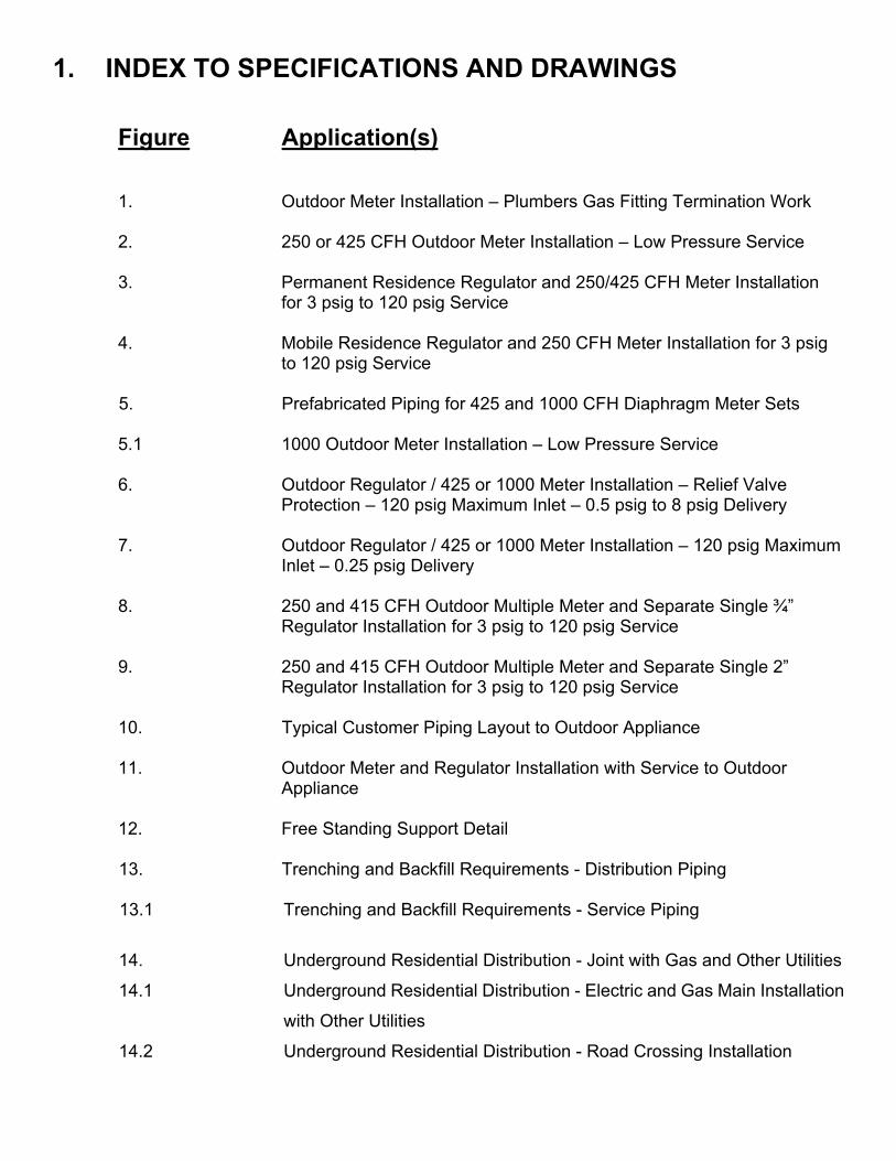
1. INDEX TO SPECIFICATIONS AND DRAWINGS
Figure Application(s) 1. Outdoor Meter Installation – Plumbers Gas Fitting Termination Work 2. 250 or 425 CFH Outdoor Meter Installation – Low Pressure Service 3. Permanent Residence Regulator and 250/425 CFH Meter Installation
for 3 psig to 120 psig Service 4. Mobile Residence Regulator and 250 CFH Meter Installation for 3 psig
to 120 psig Service
5. Prefabricated Piping for 425 and 1000 CFH Diaphragm Meter Sets 5.1 1000 Outdoor Meter Installation – Low Pressure Service 6. Outdoor Regulator / 425 or 1000 Meter Installation – Relief Valve
Protection – 120 psig Maximum Inlet – 0.5 psig to 8 psig Delivery 7. Outdoor Regulator / 425 or 1000 Meter Installation – 120 psig Maximum
Inlet – 0.25 psig Delivery 8. 250 and 415 CFH Outdoor Multiple Meter and Separate Single ¾”
Regulator Installation for 3 psig to 120 psig Service 9. 250 and 415 CFH Outdoor Multiple Meter and Separate Single 2”
Regulator Installation for 3 psig to 120 psig Service 10. Typical Customer Piping Layout to Outdoor Appliance 11. Outdoor Meter and Regulator Installation with Service to Outdoor
Appliance 12. Free Standing Support Detail
13. Trenching and Backfill Requirements - Distribution Piping 13.1 Trenching and Backfill Requirements - Service Piping
14. Underground Residential Distribution - Joint with Gas and Other Utilities
14.1 Underground Residential Distribution - Electric and Gas Main Installation
with Other Utilities
14.2 Underground Residential Distribution - Road Crossing Installation
14.3 Underground Residential Distribution - Electric and Gas Service Installation with Other Utilities
15. Typical Common Trench Configuration - Electric Ducts with Gas Main
and Other Utilities 16. Separation of Electric and Gas Meters
17. Tracer Wire Installation for Main and Service 18. Water-Tight Direct Bury Connectors for Tracer and Cathodic Wires
19. Protection of Gas Pipe for Below Grade Clearances 4” to 12”
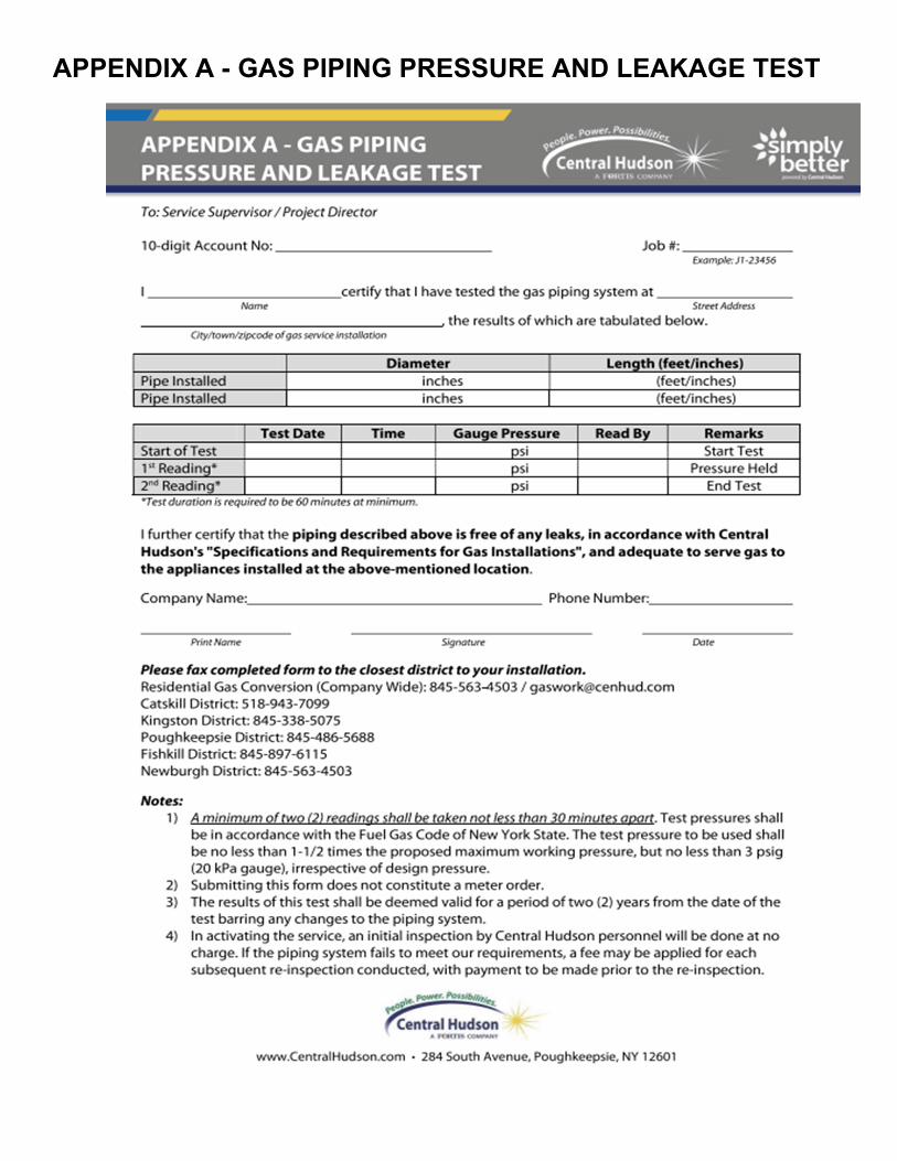
APPENDIX A - GAS PIPING PRESSURE AND LEAKAGE TEST
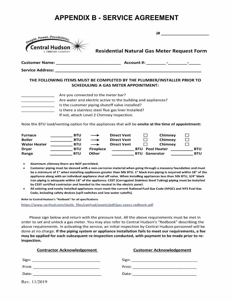
APPENDIX B - SERVICE AGREEMENT
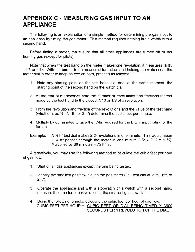
APPENDIX C - MEASURING GAS INPUT TO AN APPLIANCE
The following is an explanation of a simple method for determining the gas input to an appliance by timing the gas meter. This method requires nothing but a watch with a second hand.
Before timing a meter, make sure that all other appliances are turned off or not burning gas (except for pilots).
Note that when the test hand on the meter makes one revolution, it measures ½ ft³, 1 ft³, or 2 ft³. With the burner to be measured turned on and holding the watch near the meter dial in order to keep an eye on both, proceed as follows: 1. Note any starting point on the test hand dial and, at the same moment, the
starting point of the second hand on the watch dial.
2. At the end of 60 seconds note the number of revolutions and fractions thereof made by the test hand to the closest 1/10 or 1/8 of a revolution.
3. From the revolution and fraction of the revolutions and the value of the test hand
(whether it be ½ ft³, 1ft³, or 2 ft³) determine the cubic feet per minute.
4. Multiply by 60 minutes to give the ft³/hr required for the btu/hr input rating of the furnace.
Example: A ½ ft³ test dial makes 2 ½ revolutions in one minute. This would mean
1 ¼ ft³ passed through the meter in one minute (1/2 x 2 ½ = 1 ¼). Multiplied by 60 minutes = 75 ft³/hr.
Alternatively, you may use the following method to calculate the cubic feet per hour
of gas flow: 1. Shut off all gas appliances except the one being tested. 2. Identify the smallest gas flow dial on the gas meter (i.e., test dial at ½ ft³, 1ft³, or
2 ft³).
3. Operate the appliance and with a stopwatch or a watch with a second hand, measure the time for one revolution of the smallest gas flow dial.
4. Using the following formula, calculate the cubic feet per hour of gas flow:
CUBIC FEET PER HOUR = CUBIC FEET OF DIAL BEING TIMED X 3600 SECONDS PER 1 REVOLUTION OF THE DIAL
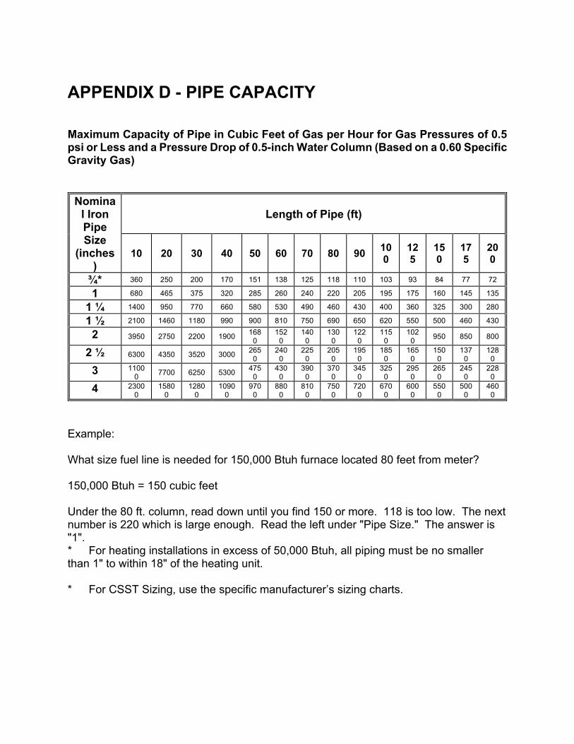
APPENDIX D - PIPE CAPACITY Maximum Capacity of Pipe in Cubic Feet of Gas per Hour for Gas Pressures of 0.5 psi or Less and a Pressure Drop of 0.5-inch Water Column (Based on a 0.60 Specific Gravity Gas)
Nominal Iron Pipe Size
(inches)
Length of Pipe (ft)
10 20 30 40 50 60 70 80 90 100
125
150
175
200
¾* 360 250 200 170 151 138 125 118 110 103 93 84 77 72
1 680 465 375 320 285 260 240 220 205 195 175 160 145 135
1 ¼ 1400 950 770 660 580 530 490 460 430 400 360 325 300 280
1 ½ 2100 1460 1180 990 900 810 750 690 650 620 550 500 460 430
2 3950 2750 2200 1900 168
0152
0140
0130
0122
0115
0102
0 950 850 800
2 ½ 6300 4350 3520 3000 265
0240
0225
0205
0195
0185
0165
0 150
0 137
0128
0
3 11000
7700 6250 5300 475
0430
0390
0370
0345
0325
0295
0 265
0 245
0228
0
4 23000
15800
12800
10900
9700
8800
8100
7500
7200
6700
6000
5500
5000
4600
Example: What size fuel line is needed for 150,000 Btuh furnace located 80 feet from meter? 150,000 Btuh = 150 cubic feet Under the 80 ft. column, read down until you find 150 or more. 118 is too low. The next number is 220 which is large enough. Read the left under "Pipe Size." The answer is "1". * For heating installations in excess of 50,000 Btuh, all piping must be no smaller than 1" to within 18" of the heating unit. * For CSST Sizing, use the specific manufacturer’s sizing charts.
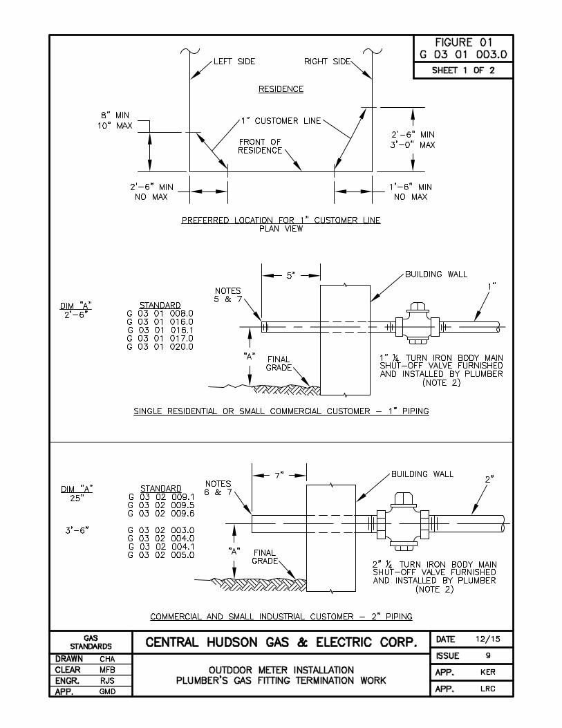
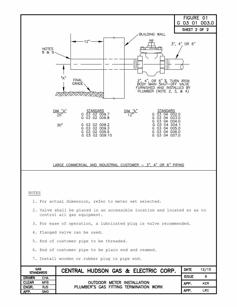
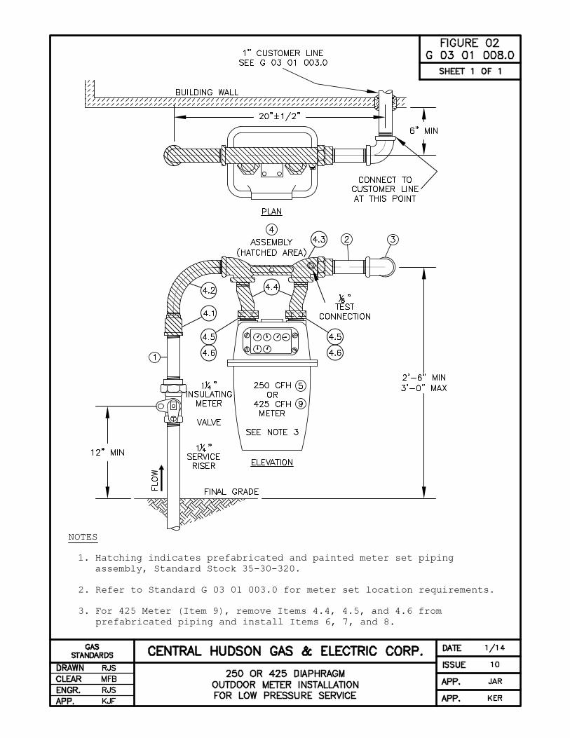
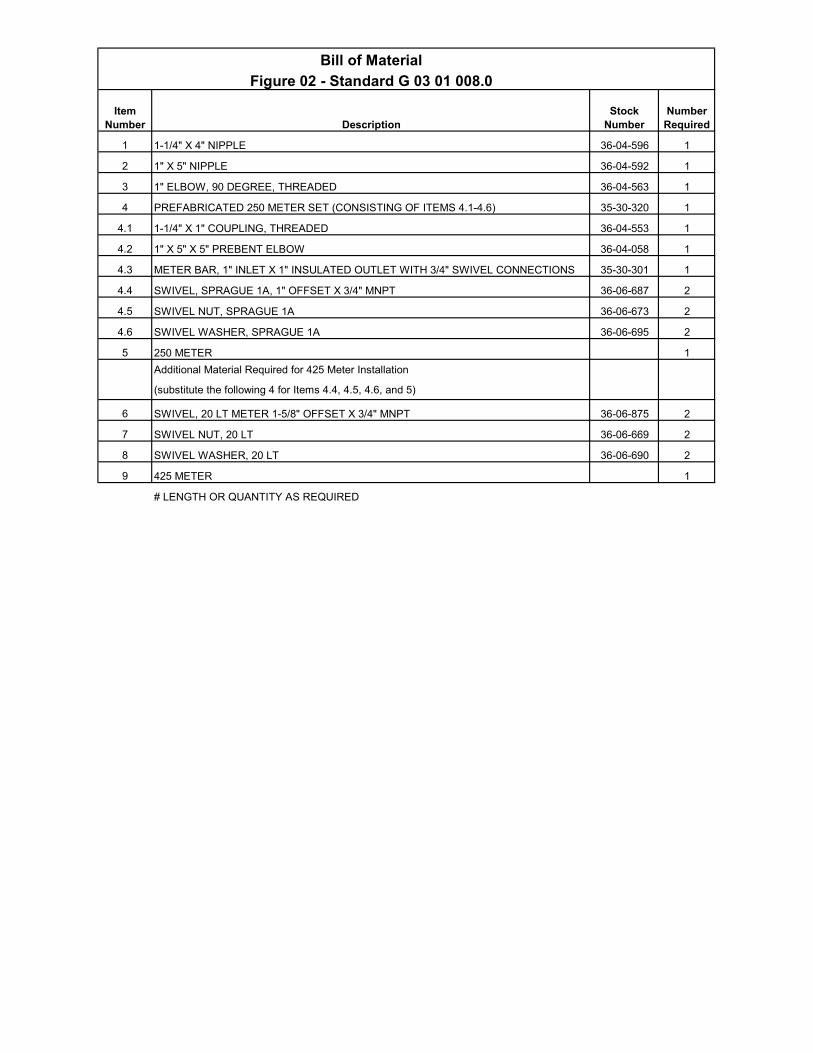
Bill of Material
Figure 02 - Standard G 03 01 008.0
Description
1 1-1/4" X 4" NIPPLE 36-04-596 1
2 1" X 5" NIPPLE 36-04-592 1
3 1" ELBOW, 90 DEGREE, THREADED 36-04-563 1
4 PREFABRICATED 250 METER SET (CONSISTING OF ITEMS 4.1-4.6) 35-30-320 1
4.1 1-1/4" X 1" COUPLING, THREADED 36-04-553 1
4.2 1" X 5" X 5" PREBENT ELBOW 36-04-058 1
4.3 METER BAR, 1" INLET X 1" INSULATED OUTLET WITH 3/4" SWIVEL CONNECTIONS 35-30-301 1
4.4 SWIVEL, SPRAGUE 1A, 1" OFFSET X 3/4" MNPT 36-06-687 2
4.5 SWIVEL NUT, SPRAGUE 1A 36-06-673 2
4.6 SWIVEL WASHER, SPRAGUE 1A 36-06-695 2
5 250 METER 1
Additional Material Required for 425 Meter Installation
(substitute the following 4 for Items 4.4, 4.5, 4.6, and 5)
6 SWIVEL, 20 LT METER 1-5/8" OFFSET X 3/4" MNPT 36-06-875 2
7 SWIVEL NUT, 20 LT 36-06-669 2
8 SWIVEL WASHER, 20 LT 36-06-690 2
9 425 METER 1
# LENGTH OR QUANTITY AS REQUIRED
Item Number
Stock Number
Number Required
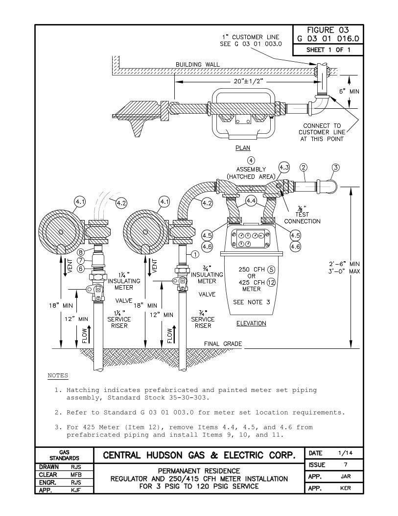
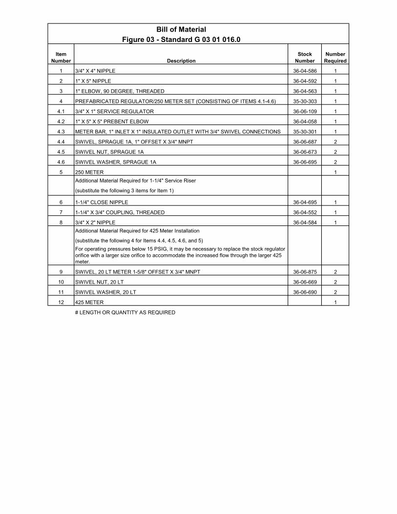
Bill of Material
Figure 03 - Standard G 03 01 016.0
Description
1 3/4" X 4" NIPPLE 36-04-586 1
2 1" X 5" NIPPLE 36-04-592 1
3 1" ELBOW, 90 DEGREE, THREADED 36-04-563 1
4 PREFABRICATED REGULATOR/250 METER SET (CONSISTING OF ITEMS 4.1-4.6) 35-30-303 1
4.1 3/4" X 1" SERVICE REGULATOR 36-06-109 1
4.2 1" X 5" X 5" PREBENT ELBOW 36-04-058 1
4.3 METER BAR, 1" INLET X 1" INSULATED OUTLET WITH 3/4" SWIVEL CONNECTIONS 35-30-301 1
4.4 SWIVEL, SPRAGUE 1A, 1" OFFSET X 3/4" MNPT 36-06-687 2
4.5 SWIVEL NUT, SPRAGUE 1A 36-06-673 2
4.6 SWIVEL WASHER, SPRAGUE 1A 36-06-695 2
5 250 METER 1
Additional Material Required for 1-1/4" Service Riser
(substitute the following 3 items for Item 1)
6 1-1/4" CLOSE NIPPLE 36-04-695 1
7 1-1/4" X 3/4" COUPLING, THREADED 36-04-552 1
8 3/4" X 2" NIPPLE 36-04-584 1
Additional Material Required for 425 Meter Installation
(substitute the following 4 for Items 4.4, 4.5, 4.6, and 5)
For operating pressures below 15 PSIG, it may be necessary to replace the stock regulator orifice with a larger size orifice to accommodate the increased flow through the larger 425 meter.
9 SWIVEL, 20 LT METER 1-5/8" OFFSET X 3/4" MNPT 36-06-875 2
10 SWIVEL NUT, 20 LT 36-06-669 2
11 SWIVEL WASHER, 20 LT 36-06-690 2
12 425 METER 1
# LENGTH OR QUANTITY AS REQUIRED
Item Number
Stock Number
Number Required
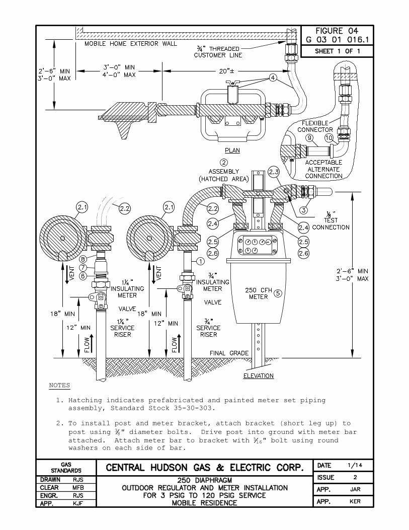
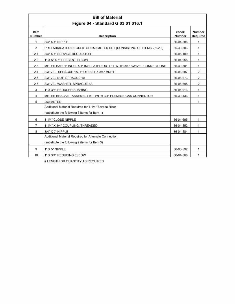
Bill of Material
Figure 04 - Standard G 03 01 016.1
Description
1 3/4" X 4" NIPPLE 36-04-586 1
2 PREFABRICATED REGULATOR/250 METER SET (CONSISTING OF ITEMS 2.1-2.6) 35-30-303 1
2.1 3/4" X 1" SERVICE REGULATOR 36-06-109 1
2.2 1" X 5" X 5" PREBENT ELBOW 36-04-058 1
2.3 METER BAR, 1" INLET X 1" INSULATED OUTLET WITH 3/4" SWIVEL CONNECTIONS 35-30-301 1
2.4 SWIVEL, SPRAGUE 1A, 1" OFFSET X 3/4" MNPT 36-06-687 2
2.5 SWIVEL NUT, SPRAGUE 1A 36-06-673 2
2.6 SWIVEL WASHER, SPRAGUE 1A 36-06-695 2
3 1" X 3/4" REDUCER BUSHING 36-04-913 1
4 METER BRACKET ASSEMBLY KIT WITH 3/4" FLEXIBLE GAS CONNECTOR 35-30-433 1
5 250 METER 1
Additional Material Required for 1-1/4" Service Riser
(substitute the following 3 items for Item 1)
6 1-1/4" CLOSE NIPPLE 36-04-695 1
7 1-1/4" X 3/4" COUPLING, THREADED 36-04-552 1
8 3/4" X 2" NIPPLE 36-04-584 1
Additional Material Required for Alternate Connection
(substitute the following 2 items for Item 3)
9 1" X 5" NIPPLE 36-06-592 1
10 1" X 3/4" REDUCING ELBOW 36-04-566 1
# LENGTH OR QUANTITY AS REQUIRED
Item Number
Stock Number
Number Required
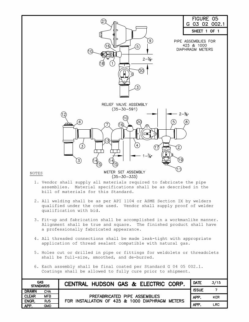
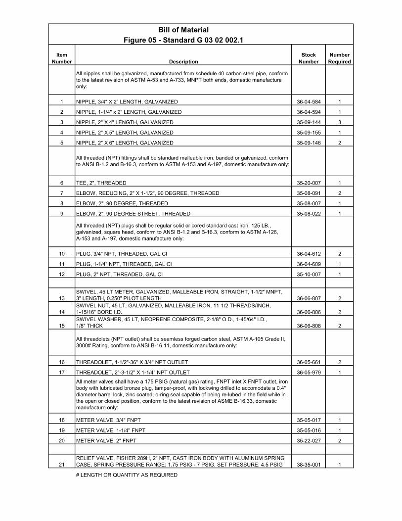
Bill of Material
Figure 05 - Standard G 03 02 002.1
Description
All nipples shall be galvanized, manufactured from schedule 40 carbon steel pipe, conform to the latest revision of ASTM A-53 and A-733, MNPT both ends, domestic manufacture only:
1 NIPPLE, 3/4" X 2" LENGTH, GALVANIZED 36-04-584 1
2 NIPPLE, 1-1/4" x 2" LENGTH, GALVANIZED 36-04-594 1
3 NIPPLE, 2" X 4" LENGTH, GALVANIZED 35-09-144 3
4 NIPPLE, 2" X 5" LENGTH, GALVANIZED 35-09-155 1
5 NIPPLE, 2" X 6" LENGTH, GALVANIZED 35-09-146 2
All threaded (NPT) fittings shall be standard malleable iron, banded or galvanized, conform to ANSI B-1.2 and B-16.3, conform to ASTM A-153 and A-197, domestic manufacture only:
6 TEE, 2", THREADED 35-20-007 1
7 ELBOW, REDUCING, 2" X 1-1/2", 90 DEGREE, THREADED 35-08-091 2
8 ELBOW, 2", 90 DEGREE, THREADED 35-08-007 1
9 ELBOW, 2", 90 DEGREE STREET, THREADED 35-08-022 1
All threaded (NPT) plugs shall be regular solid or cored standard cast iron, 125 LB., galvanized, square head, conform to ANSI B-1.2 and B-16.3, conform to ASTM A-126, A-153 and A-197, domestic manufacture only:
10 PLUG, 3/4" NPT, THREADED, GAL CI 36-04-612 2
11 PLUG, 1-1/4" NPT, THREADED, GAL CI 36-04-609 1
12 PLUG, 2" NPT, THREADED, GAL CI 35-10-007 1
13SWIVEL, 45 LT METER, GALVANIZED, MALLEABLE IRON, STRAIGHT, 1-1/2" MNPT, 3" LENGTH, 0.250" PILOT LENGTH 36-06-807 2
14SWIVEL NUT, 45 LT, GALVANIZED, MALLEABLE IRON, 11-1/2 THREADS/INCH, 1-15/16" BORE I.D. 36-06-806 2
15SWIVEL WASHER, 45 LT, NEOPRENE COMPOSITE, 2-1/8" O.D., 1-45/64" I.D., 1/8" THICK 36-06-808 2
All threadolets (NPT outlet) shall be seamless forged carbon steel, ASTM A-105 Grade II, 3000# Rating, conform to ANSI B-16.11, domestic manufacture only:
16 THREADOLET, 1-1/2"-36" X 3/4" NPT OUTLET 36-05-661 2
17 THREADOLET, 2"-3-1/2" X 1-1/4" NPT OUTLET 36-05-979 1
All meter valves shall have a 175 PSIG (natural gas) rating, FNPT inlet X FNPT outlet, iron body with lubricated bronze plug, tamper-proof, with lockwing drilled to accomodate a 0.4" diameter barrel lock, zinc coated, o-ring seal capable of being re-lubed in the field while in the open or closed position, conform to the latest revision of ASME B-16.33, domestic manufacture only:
18 METER VALVE, 3/4" FNPT 35-05-017 1
19 METER VALVE, 1-1/4" FNPT 35-05-016 1
20 METER VALVE, 2" FNPT 35-22-027 2
21RELIEF VALVE, FISHER 289H, 2" NPT, CAST IRON BODY WITH ALUMINUM SPRING CASE, SPRING PRESSURE RANGE: 1.75 PSIG - 7 PSIG, SET PRESSURE: 4.5 PSIG 38-35-001 1
# LENGTH OR QUANTITY AS REQUIRED
Item Number
Stock Number
Number Required
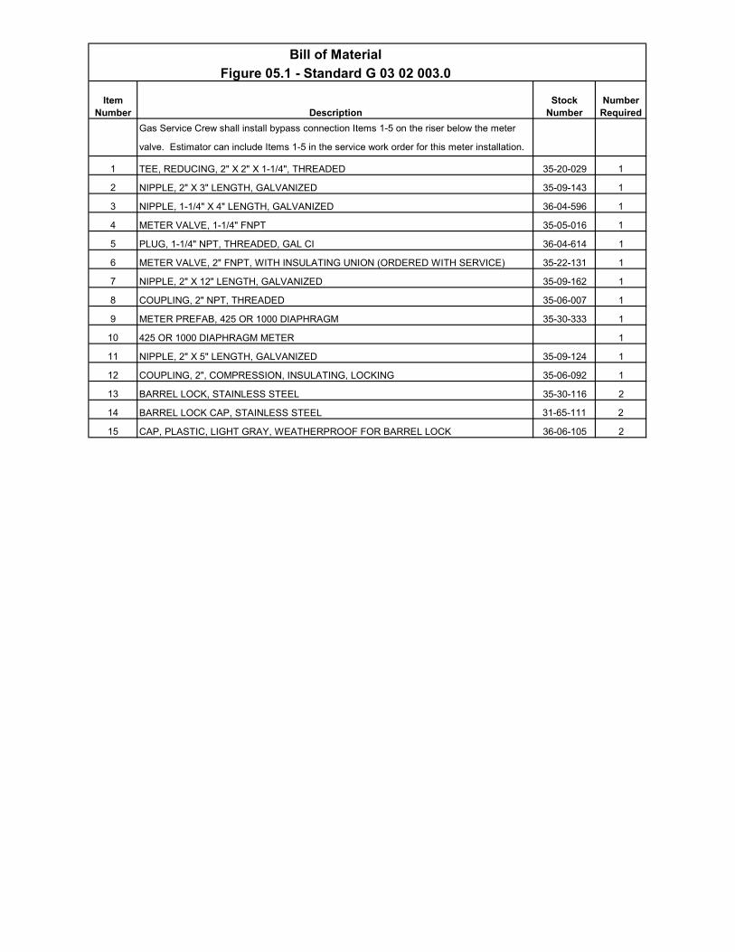
Bill of Material
Figure 05.1 - Standard G 03 02 003.0
Description
Gas Service Crew shall install bypass connection Items 1-5 on the riser below the meter
valve. Estimator can include Items 1-5 in the service work order for this meter installation.
1 TEE, REDUCING, 2" X 2" X 1-1/4", THREADED 35-20-029 1
2 NIPPLE, 2" X 3" LENGTH, GALVANIZED 35-09-143 1
3 NIPPLE, 1-1/4" X 4" LENGTH, GALVANIZED 36-04-596 1
4 METER VALVE, 1-1/4" FNPT 35-05-016 1
5 PLUG, 1-1/4" NPT, THREADED, GAL CI 36-04-614 1
6 METER VALVE, 2" FNPT, WITH INSULATING UNION (ORDERED WITH SERVICE) 35-22-131 1
7 NIPPLE, 2" X 12" LENGTH, GALVANIZED 35-09-162 1
8 COUPLING, 2" NPT, THREADED 35-06-007 1
9 METER PREFAB, 425 OR 1000 DIAPHRAGM 35-30-333 1
10 425 OR 1000 DIAPHRAGM METER 1
11 NIPPLE, 2" X 5" LENGTH, GALVANIZED 35-09-124 1
12 COUPLING, 2", COMPRESSION, INSULATING, LOCKING 35-06-092 1
13 BARREL LOCK, STAINLESS STEEL 35-30-116 2
14 BARREL LOCK CAP, STAINLESS STEEL 31-65-111 2
15 CAP, PLASTIC, LIGHT GRAY, WEATHERPROOF FOR BARREL LOCK 36-06-105 2
Item Number
Stock Number
Number Required
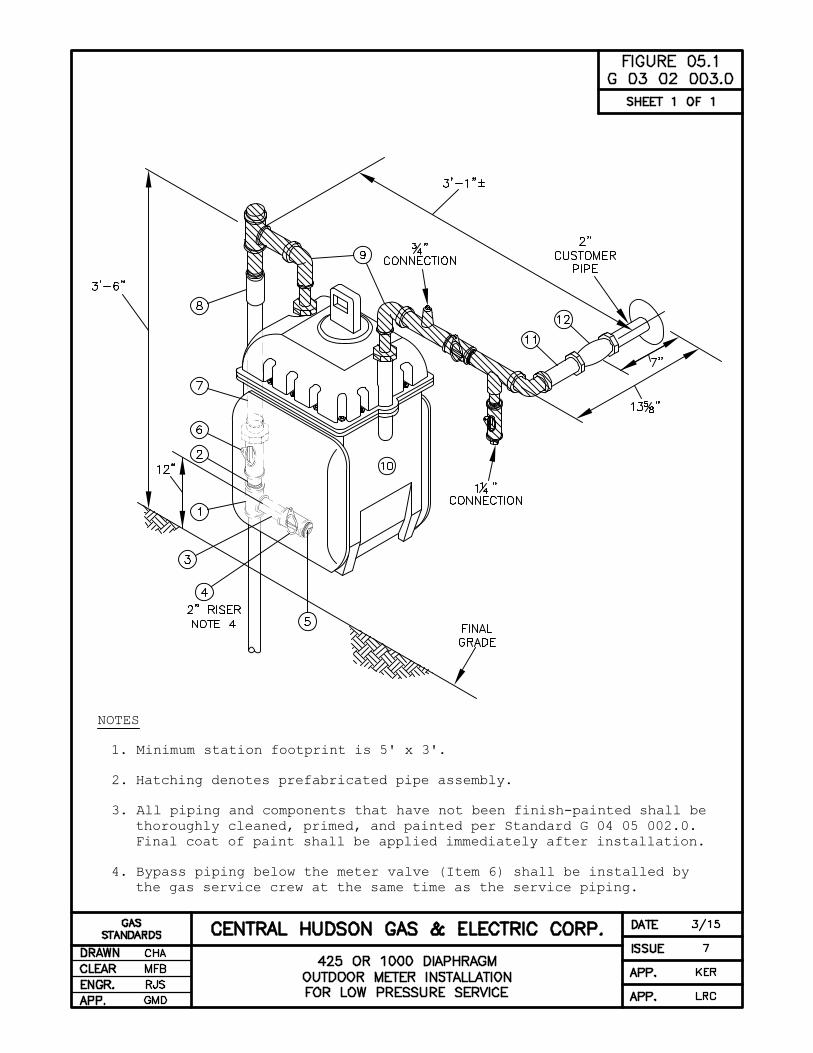
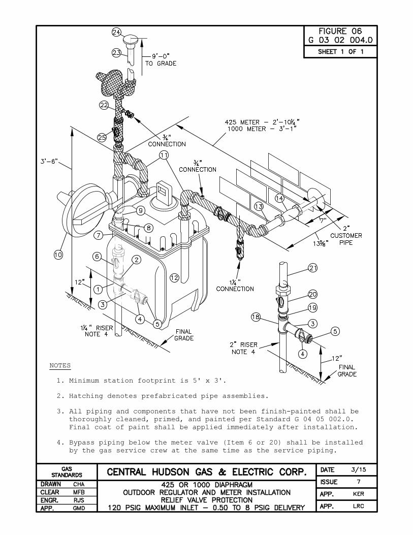
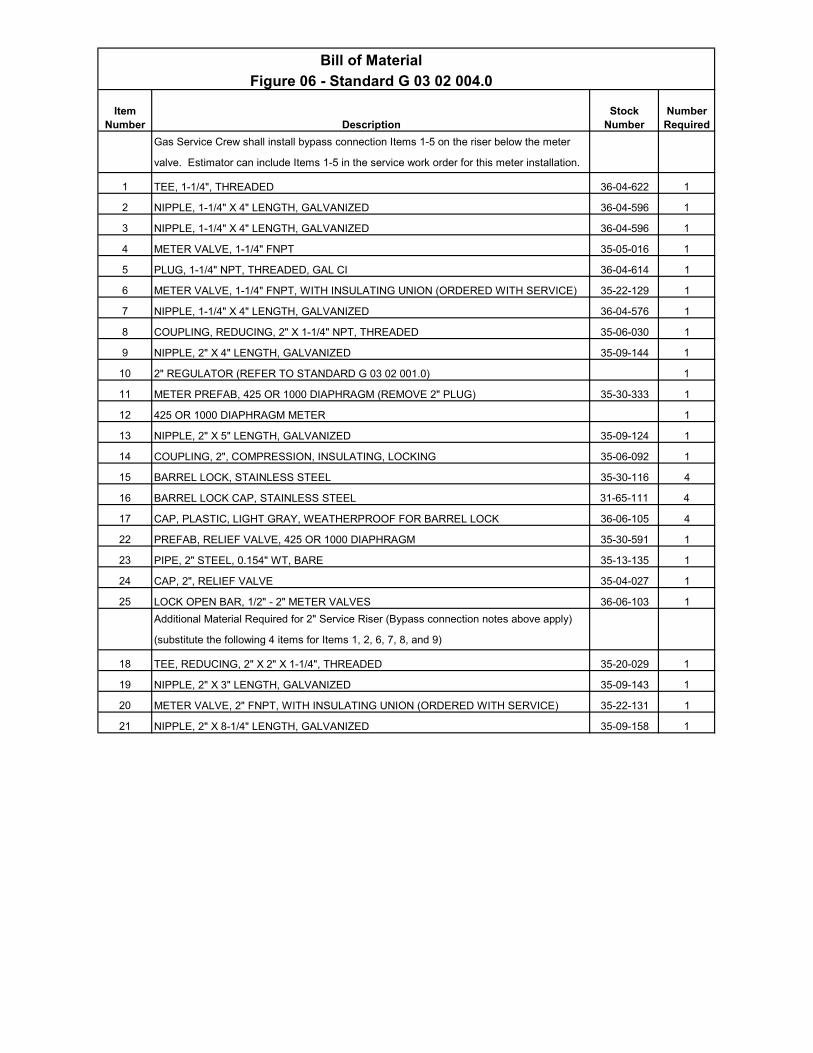
Bill of Material
Figure 06 - Standard G 03 02 004.0
Description
Gas Service Crew shall install bypass connection Items 1-5 on the riser below the meter
valve. Estimator can include Items 1-5 in the service work order for this meter installation.
1 TEE, 1-1/4", THREADED 36-04-622 1
2 NIPPLE, 1-1/4" X 4" LENGTH, GALVANIZED 36-04-596 1
3 NIPPLE, 1-1/4" X 4" LENGTH, GALVANIZED 36-04-596 1
4 METER VALVE, 1-1/4" FNPT 35-05-016 1
5 PLUG, 1-1/4" NPT, THREADED, GAL CI 36-04-614 1
6 METER VALVE, 1-1/4" FNPT, WITH INSULATING UNION (ORDERED WITH SERVICE) 35-22-129 1
7 NIPPLE, 1-1/4" X 4" LENGTH, GALVANIZED 36-04-576 1
8 COUPLING, REDUCING, 2" X 1-1/4" NPT, THREADED 35-06-030 1
9 NIPPLE, 2" X 4" LENGTH, GALVANIZED 35-09-144 1
10 2" REGULATOR (REFER TO STANDARD G 03 02 001.0) 1
11 METER PREFAB, 425 OR 1000 DIAPHRAGM (REMOVE 2" PLUG) 35-30-333 1
12 425 OR 1000 DIAPHRAGM METER 1
13 NIPPLE, 2" X 5" LENGTH, GALVANIZED 35-09-124 1
14 COUPLING, 2", COMPRESSION, INSULATING, LOCKING 35-06-092 1
15 BARREL LOCK, STAINLESS STEEL 35-30-116 4
16 BARREL LOCK CAP, STAINLESS STEEL 31-65-111 4
17 CAP, PLASTIC, LIGHT GRAY, WEATHERPROOF FOR BARREL LOCK 36-06-105 4
22 PREFAB, RELIEF VALVE, 425 OR 1000 DIAPHRAGM 35-30-591 1
23 PIPE, 2" STEEL, 0.154" WT, BARE 35-13-135 1
24 CAP, 2", RELIEF VALVE 35-04-027 1
25 LOCK OPEN BAR, 1/2" - 2" METER VALVES 36-06-103 1
Additional Material Required for 2" Service Riser (Bypass connection notes above apply)
(substitute the following 4 items for Items 1, 2, 6, 7, 8, and 9)
18 TEE, REDUCING, 2" X 2" X 1-1/4", THREADED 35-20-029 1
19 NIPPLE, 2" X 3" LENGTH, GALVANIZED 35-09-143 1
20 METER VALVE, 2" FNPT, WITH INSULATING UNION (ORDERED WITH SERVICE) 35-22-131 1
21 NIPPLE, 2" X 8-1/4" LENGTH, GALVANIZED 35-09-158 1
Item Number
Stock Number
Number Required
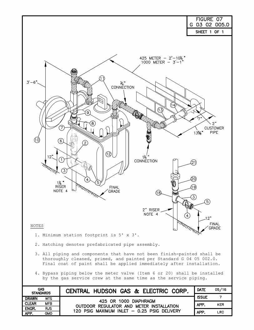
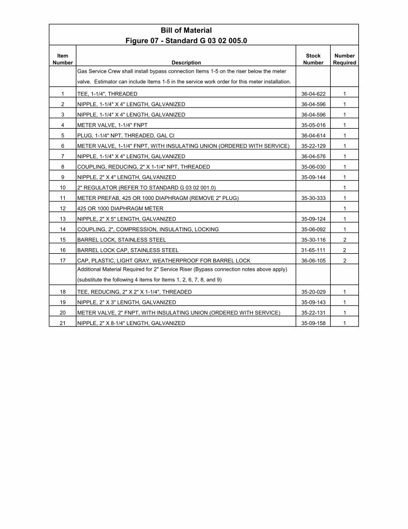
Bill of Material
Figure 07 - Standard G 03 02 005.0
Description
Gas Service Crew shall install bypass connection Items 1-5 on the riser below the meter
valve. Estimator can include Items 1-5 in the service work order for this meter installation.
1 TEE, 1-1/4", THREADED 36-04-622 1
2 NIPPLE, 1-1/4" X 4" LENGTH, GALVANIZED 36-04-596 1
3 NIPPLE, 1-1/4" X 4" LENGTH, GALVANIZED 36-04-596 1
4 METER VALVE, 1-1/4" FNPT 35-05-016 1
5 PLUG, 1-1/4" NPT, THREADED, GAL CI 36-04-614 1
6 METER VALVE, 1-1/4" FNPT, WITH INSULATING UNION (ORDERED WITH SERVICE) 35-22-129 1
7 NIPPLE, 1-1/4" X 4" LENGTH, GALVANIZED 36-04-576 1
8 COUPLING, REDUCING, 2" X 1-1/4" NPT, THREADED 35-06-030 1
9 NIPPLE, 2" X 4" LENGTH, GALVANIZED 35-09-144 1
10 2" REGULATOR (REFER TO STANDARD G 03 02 001.0) 1
11 METER PREFAB, 425 OR 1000 DIAPHRAGM (REMOVE 2" PLUG) 35-30-333 1
12 425 OR 1000 DIAPHRAGM METER 1
13 NIPPLE, 2" X 5" LENGTH, GALVANIZED 35-09-124 1
14 COUPLING, 2", COMPRESSION, INSULATING, LOCKING 35-06-092 1
15 BARREL LOCK, STAINLESS STEEL 35-30-116 2
16 BARREL LOCK CAP, STAINLESS STEEL 31-65-111 2
17 CAP, PLASTIC, LIGHT GRAY, WEATHERPROOF FOR BARREL LOCK 36-06-105 2
Additional Material Required for 2" Service Riser (Bypass connection notes above apply)
(substitute the following 4 items for Items 1, 2, 6, 7, 8, and 9)
18 TEE, REDUCING, 2" X 2" X 1-1/4", THREADED 35-20-029 1
19 NIPPLE, 2" X 3" LENGTH, GALVANIZED 35-09-143 1
20 METER VALVE, 2" FNPT, WITH INSULATING UNION (ORDERED WITH SERVICE) 35-22-131 1
21 NIPPLE, 2" X 8-1/4" LENGTH, GALVANIZED 35-09-158 1
Item Number
Stock Number
Number Required
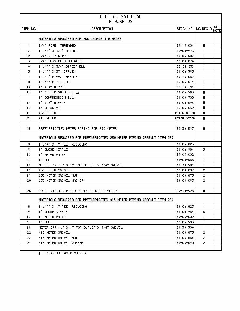
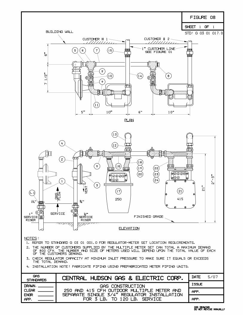
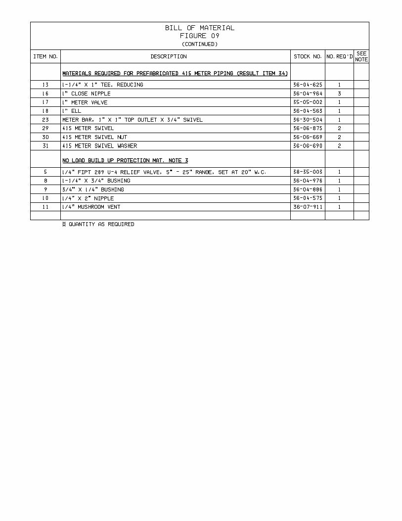
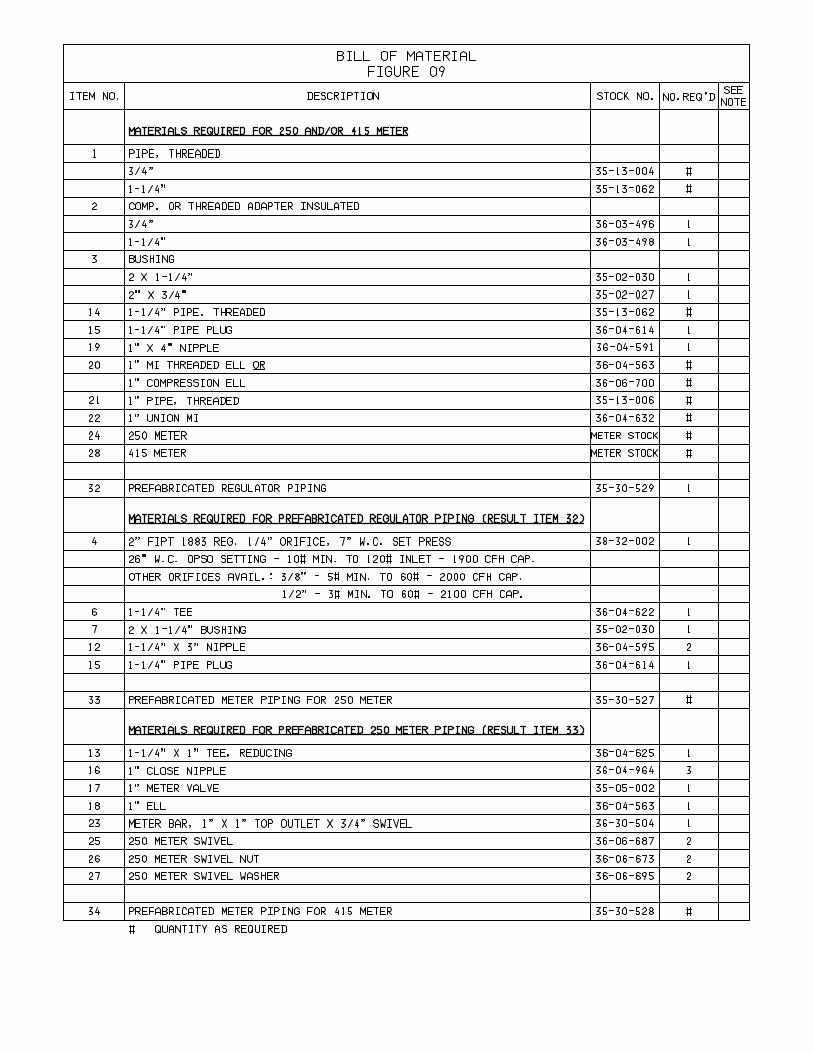
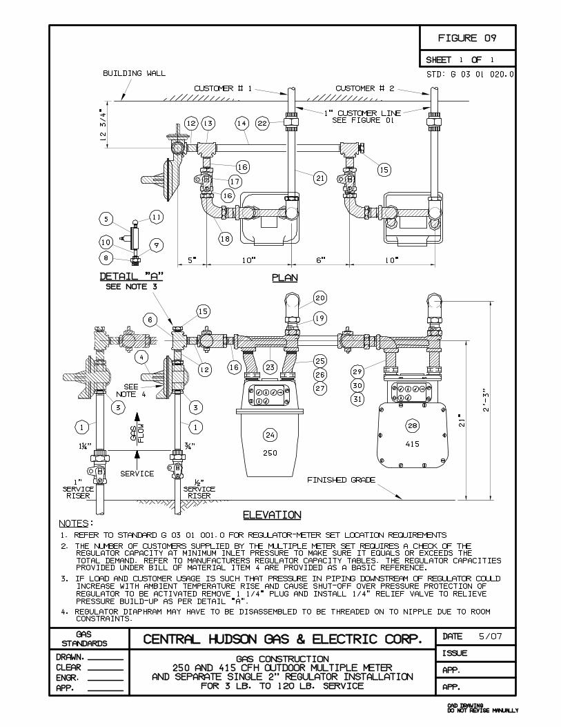
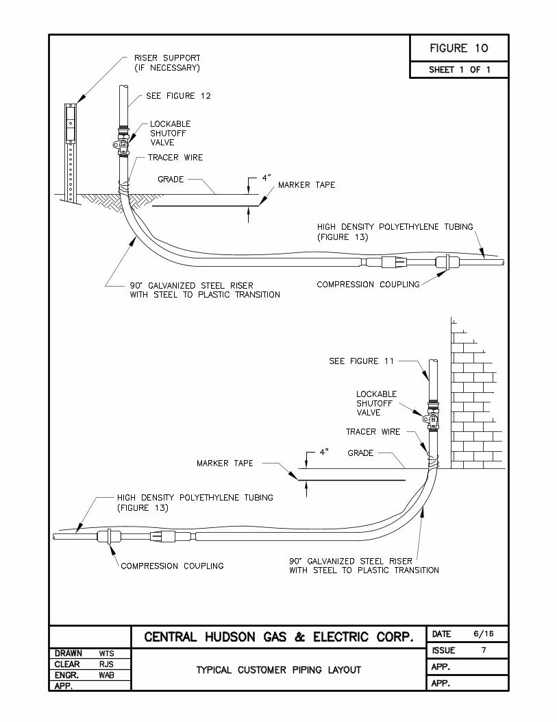
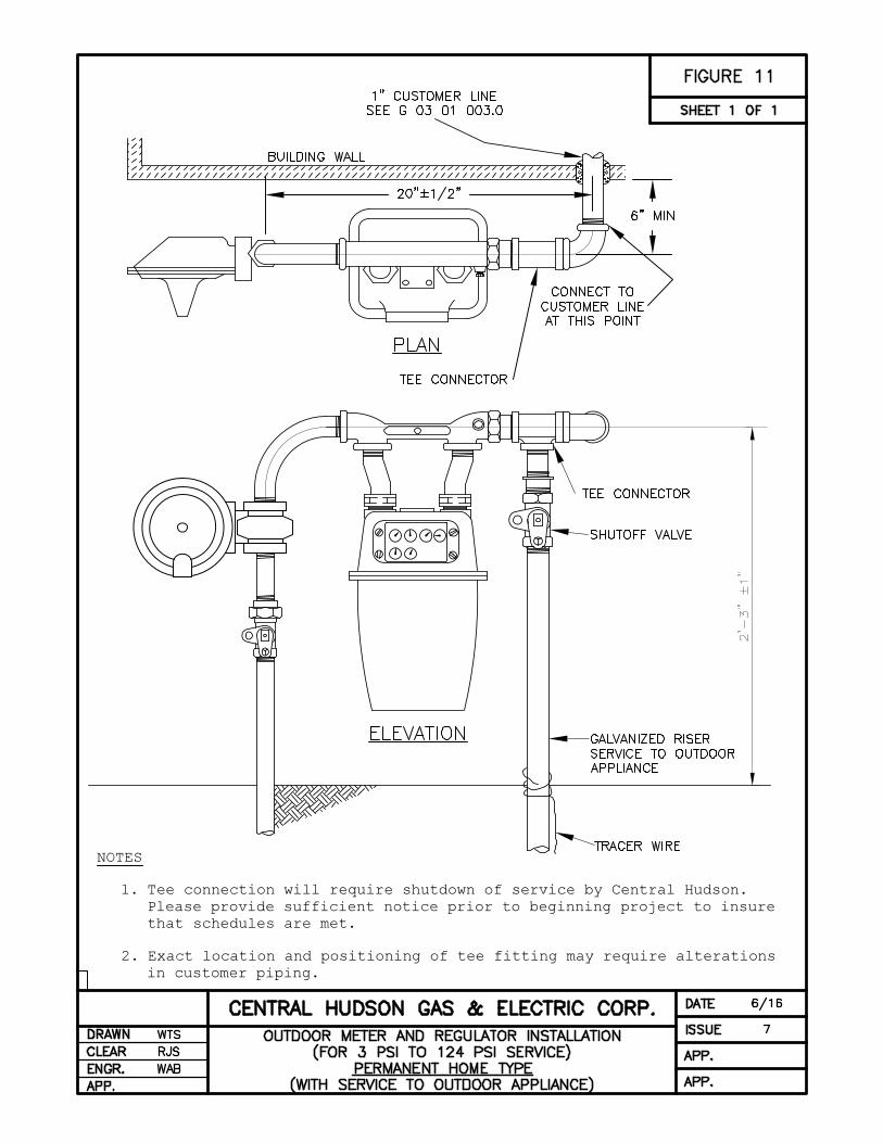
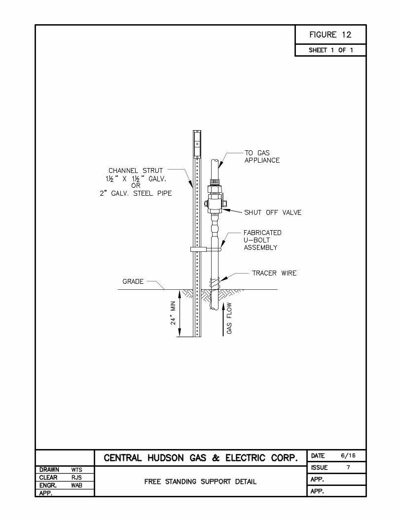
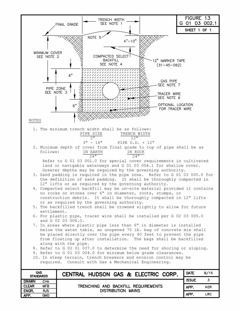
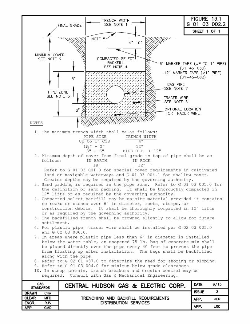
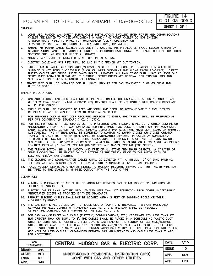
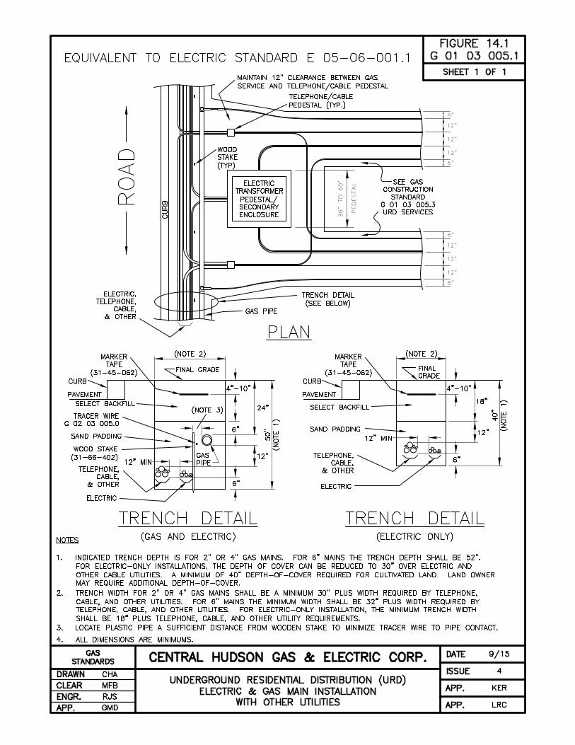
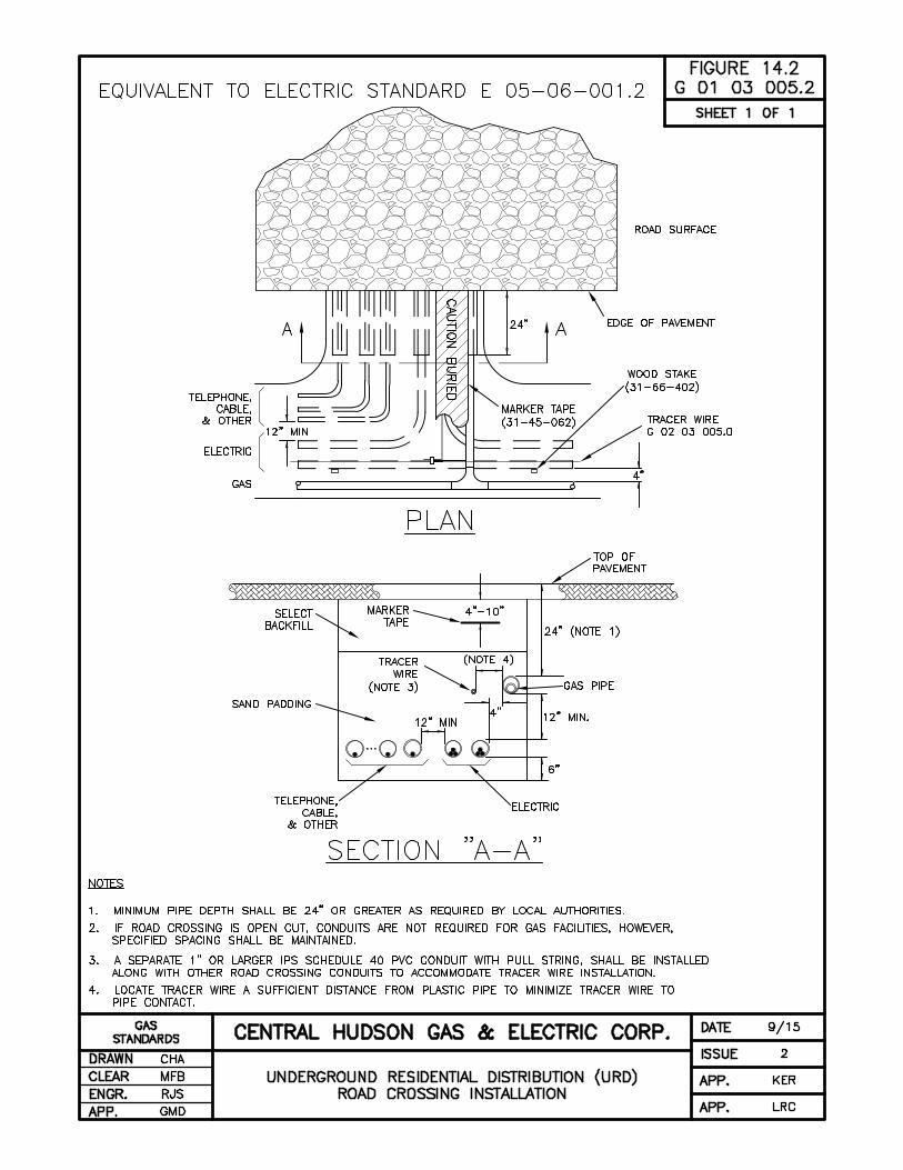
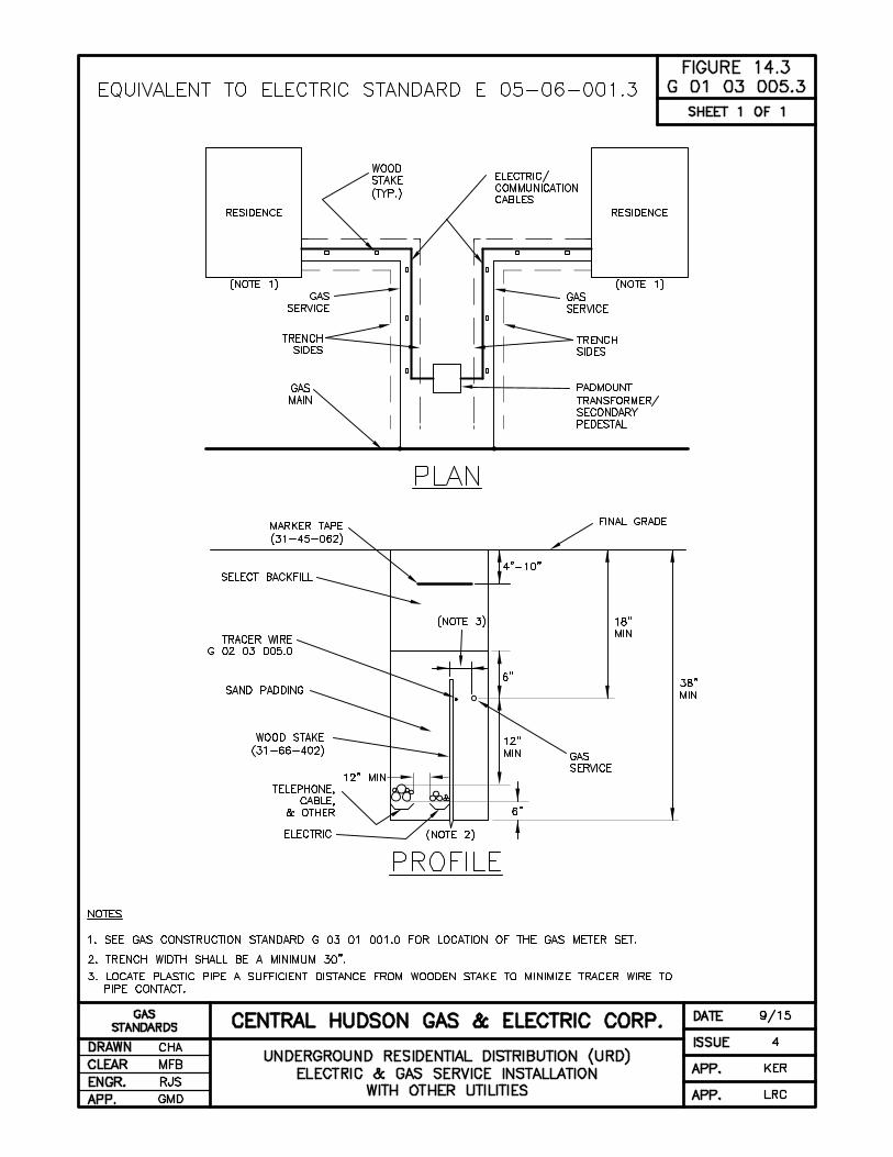
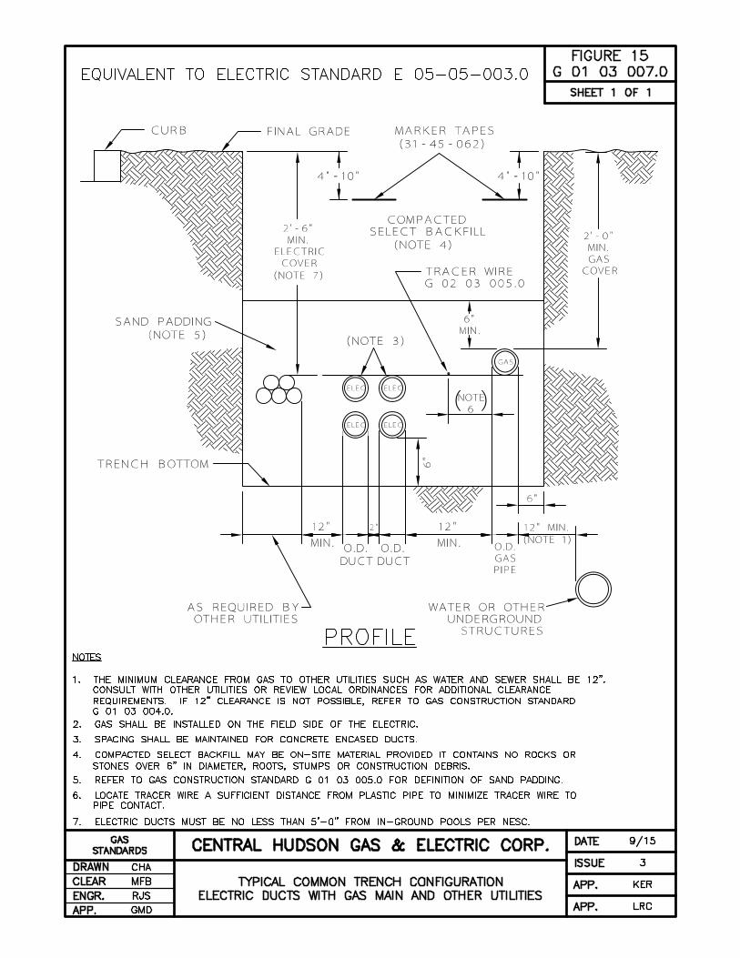
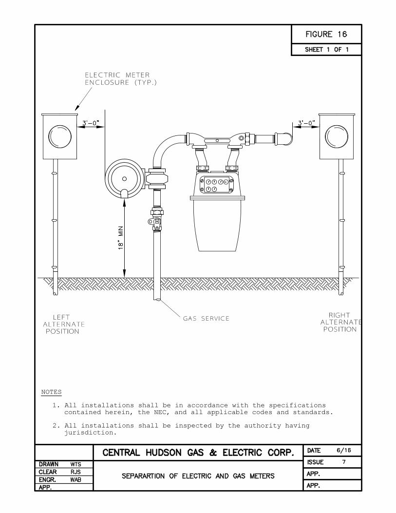
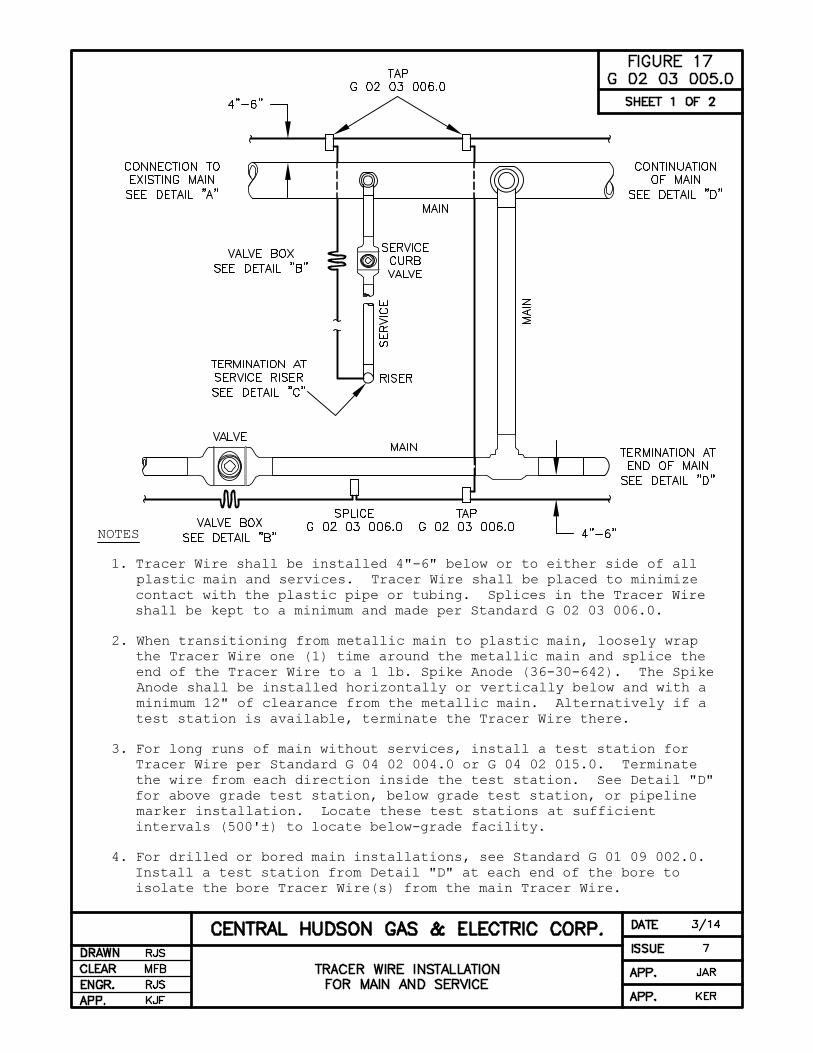
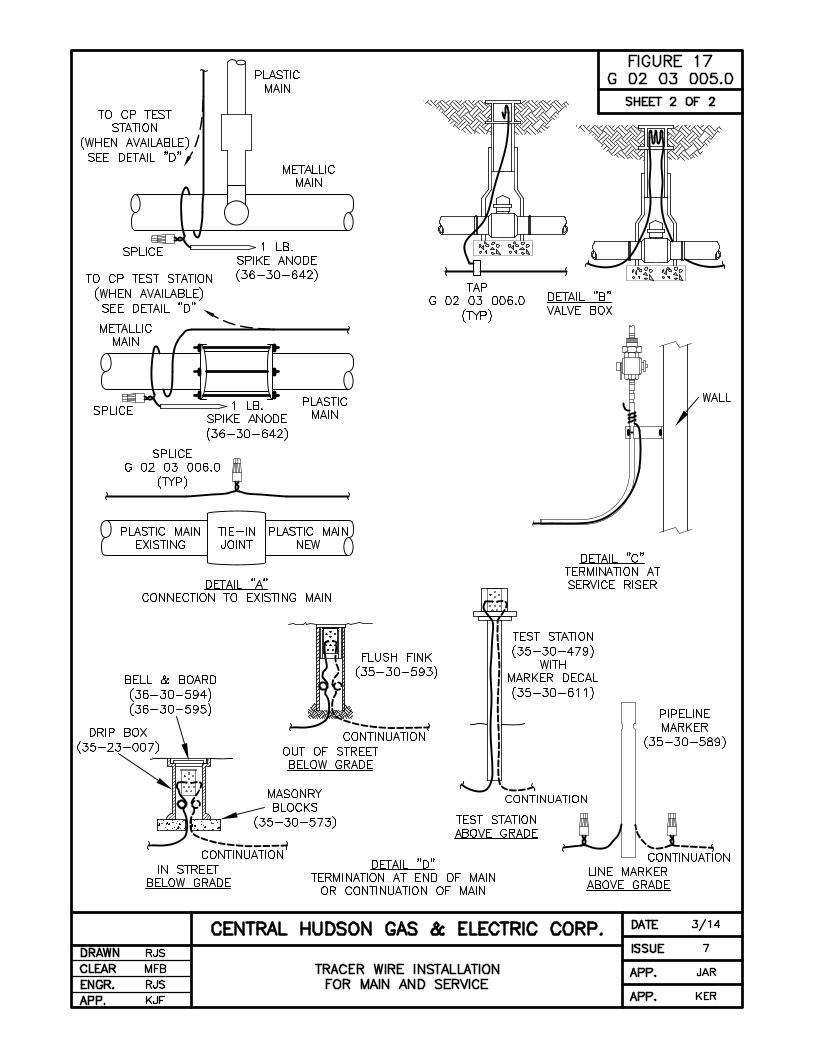
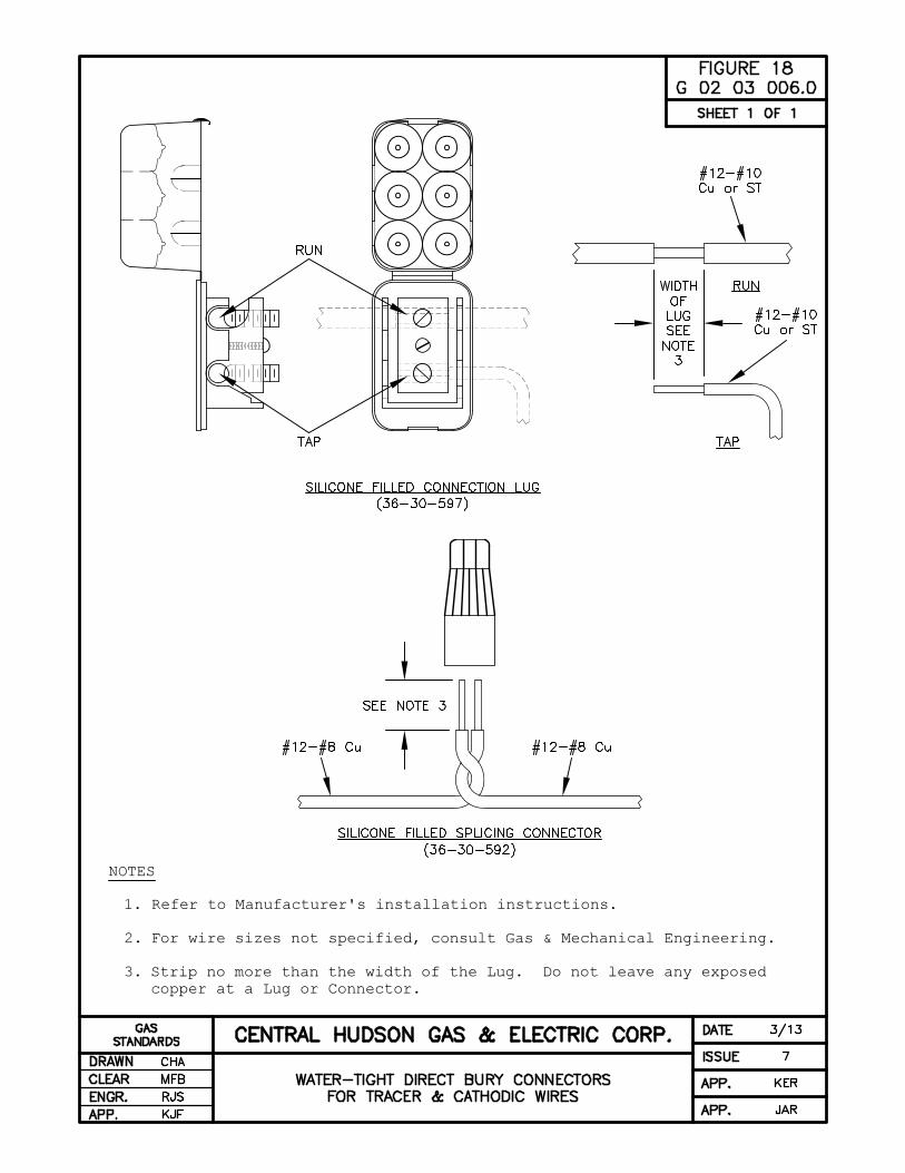
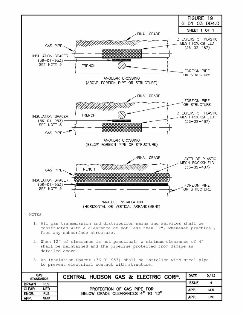
Report any and all suspected gas leaks to
Central Hudson by calling this special, 24-hour, toll-
free hotline:
1-800-942-8274

Directory of Company Offices
Central Hudson Gas & Electric Corp. Spec. and Req. for Gas Installations
This page was intentionally left blank.
Central Hudson Gas & Electric Corp.


Central Hudson Gas & Electric Corporation