Embed Size (px)
Citation preview
May 23, 2016 1
SPECIFICATIONS
FOR ROADWAY DESIGN, PAVING AND DRAINAGE IMPROVEMENTS
HAYS COUNTY, TEXAS
DESIGN STANDARDS: Unless specifically noted below, default standards shall be the most current City of Austin (COA)
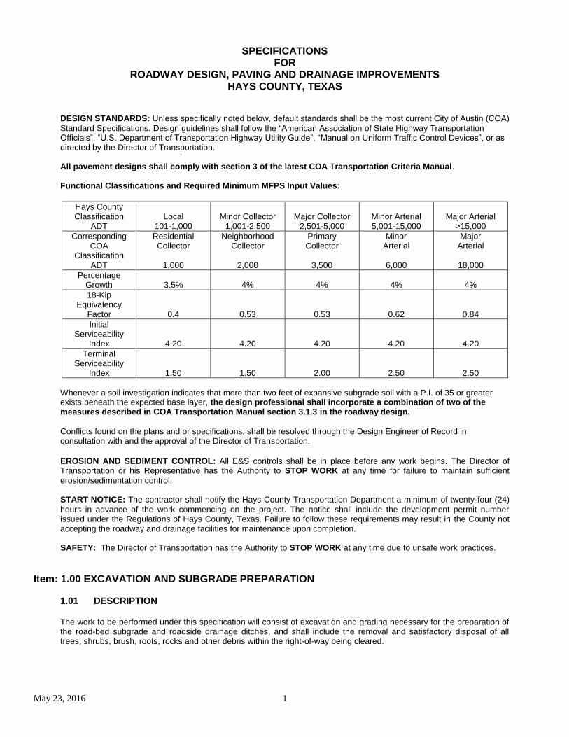
Standard Specifications. Design guidelines shall follow the “American Association of State Highway Transportation Officials”, “U.S. Department of Transportation Highway Utility Guide”, “Manual on Uniform Traffic Control Devices”, or as directed by the Director of Transportation. All pavement designs shall comply with section 3 of the latest COA Transportation Criteria Manual. Functional Classifications and Required Minimum MFPS Input Values:
Hays County Classification
ADT
Local
101-1,000 Minor Collector
1,001-2,500 Major Collector
2,501-5,000
Minor Arterial 5,001-15,000
Major Arterial
>15,000
Corresponding COA
Classification ADT
Residential Collector
1,000
Neighborhood Collector
2,000
Primary Collector
3,500
Minor Arterial
6,000
Major Arterial
18,000
Percentage Growth
3.5%
4%
4%
4%
4%
18-Kip Equivalency
Factor
0.4
0.53
0.53
0.62
0.84
Initial Serviceability
Index
4.20
4.20
4.20
4.20
4.20
Terminal Serviceability
Index
1.50
1.50
2.00
2.50
2.50
Whenever a soil investigation indicates that more than two feet of expansive subgrade soil with a P.I. of 35 or greater exists beneath the expected base layer, the design professional shall incorporate a combination of two of the measures described in COA Transportation Manual section 3.1.3 in the roadway design.
Conflicts found on the plans and or specifications, shall be resolved through the Design Engineer of Record in consultation with and the approval of the Director of Transportation.
EROSION AND SEDIMENT CONTROL: All E&S controls shall be in place before any work begins. The Director of Transportation or his Representative has the Authority to STOP WORK at any time for failure to maintain sufficient
erosion/sedimentation control. START NOTICE: The contractor shall notify the Hays County Transportation Department a minimum of twenty-four (24)
hours in advance of the work commencing on the project. The notice shall include the development permit number issued under the Regulations of Hays County, Texas. Failure to follow these requirements may result in the County not accepting the roadway and drainage facilities for maintenance upon completion. SAFETY: The Director of Transportation has the Authority to STOP WORK at any time due to unsafe work practices.
Item: 1.00 EXCAVATION AND SUBGRADE PREPARATION
1.01 DESCRIPTION
The work to be performed under this specification will consist of excavation and grading necessary for the preparation of the road-bed subgrade and roadside drainage ditches, and shall include the removal and satisfactory disposal of all trees, shrubs, brush, roots, rocks and other debris within the right-of-way being cleared.
May 23, 2016 2
1.02 CONSTRUCTION METHODS After the site of the work has been properly cleared, excavation and grading shall proceed in conformance with the plans and specifications, and as directed by the Director of Transportation or his Representative. When required by the plans and specifications, selected materials from the excavation shall be utilized to improve the road-bed, in which case the work shall be performed in such manner and sequence that suitable materials may be selected, removed separately and deposited in the roadway within the limits and to the required elevations shown on the plans. If unsuitable subgrade material is encountered, this material shall be excavated to a depth as required by the Director of Transportation or his Representative and replaced with approved material in compacted lifts no greater than 6” compacted in depth. Care shall be exercised so as not to disturb the natural ground below the compacted subgrade limits except for the construction of structures, or when so ordered by the Director of Transportation or his Representative. The finished grades, slopes and edges of the excavation shall be backfilled where necessary, using select materials thoroughly compacted and dressed off uniformly in a neat and workmanlike manner. The Contractor shall at all times make ample provisions for completely and readily draining the subgrades and excavations.
1.03 EMBANKMENTS / FILLS
Embankments or fills shall be constructed at the locations and to the lines and grades shown on the plans. The underlying subgrade shall be scarified and benched as required in conformance with TxDOT item 132. Materials placed in fills shall be free from all organic matter, trash, frozen materials, and stone having a maximum dimension greater than six inches. Fills shall be formed of excavated materials placed in successive lifts of such widths and lengths as are suited to the moisture conditioning and compaction method utilized. Embankments shall be constructed in lifts not exceeding six inches in thickness after compaction. The Contractor shall add moisture to, or shall dry by scarification each lift as may be necessary to meet the requirements of the moisture/density specification. The addition of moisture to or drying of each lift shall be accompanied with thorough mixing so as to bring all the material to a uniform moisture content. Compaction shall be accomplished with tamping rollers, discs, and pneumatic rollers of approved design. Tamping rollers shall be used except for the final rolling of the completed fill which shall be accomplished by rubber-tired rollers. The rollers, unless otherwise directed, shall be operated at a speed between two and three miles per hour. All soft areas that develop during construction operations shall be scarified, aerated or moistened as required, and compacted to the full depth required to obtain the specified density of 95% for each layer. Portions of embankments which are too near adjacent walls, pavements or other fixed objects to permit use of the above specified rolling equipment for compacting, and other portions which the roller cannot reach for any reason, shall be thoroughly compacted by tamping in two-inch lifts with mechanical tampers or other equipment as approved by the Director of Transportation or his Representative. The degree of compaction for such portions of the embankments shall be equivalent to that obtained by moisture conditioning and rolling as specified for other respective portions of the embankment. Damaged walls, pavements, or other fixed objects shall be replaced or repaired at the expense of the Contractor. Approved material, excavated in preparation of the subgrade, may be utilized in the construction of adjacent shoulders and slopes or otherwise disposed of as directed by the Director of Transportation or his Representative. Any additional material required for the completion of the shoulders and slopes shall be secured from approved sources. After compaction, in-place moisture density tests shall be required at intervals no less than 300 feet, at locations representative of the entire roadway. Intermediate points will be tested if required by the Director of Transportation or his Representative. The cost of these tests shall be borne by the Developer or Contractor.
May 23, 2016 3
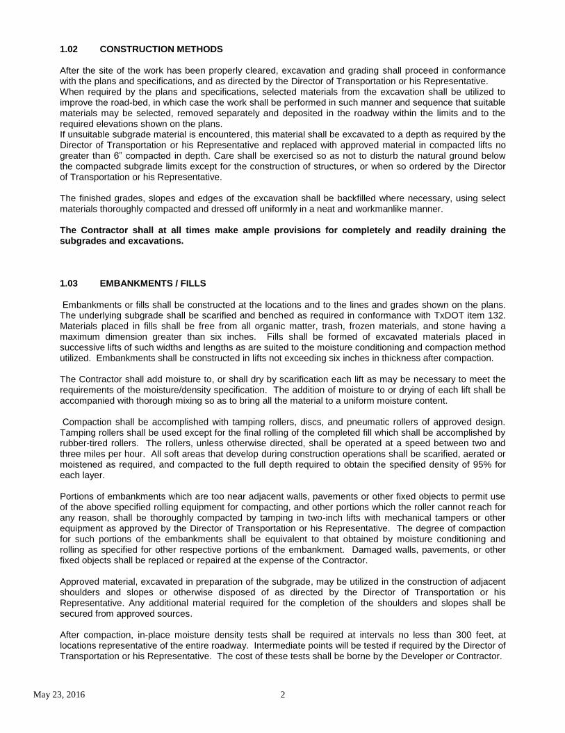
All road subgrade, embankments, and trench backfill shall be compacted to a minimum density of ninety-five percent (95%) of the maximum dry density using TxDOT test method TEX-114-E (All lifts, including ones that have passed density tests are subject to proof roll). Subgrade materials on which vegetation will be established shall be compacted to a minimum of eighty five percent (85%).
Soil Description- P.I. Required % Compaction Moisture
Non-swelling- P.I. <20 95 to 105 -3% to +3%
Swelling- P.I. of 20 to 35 95 to 102 Optimum to +4%
Swelling- P.I. >35 95 to 100 Not less than optimum
1.04 EARTH CUTS All cut areas shall be scarified to a minimum depth of 6” below grade, and all unsuitable, organic, and oversized (6”+) material removed. Scarification may be waived when a rock ledge is identified and its location noted by the Geotechnical Engineer. The Contractor shall add moisture to, or shall dry by aeration as may be necessary to meet the requirements of the moisture/density specification. Compaction shall be accomplished with tamping rollers, discs, and pneumatic rollers of approved design. Tamping rollers shall be used except for the final rolling which shall be accomplished by rubber-tired or flat wheel rollers. 1.05 MAINTENANCE OF THE FINISHED SUBGRADE The finish subgrade shall be maintained to the proper grade, cross section, density, and moisture requirements by the Contractor until subbase or base material is placed thereon. All such maintenance, including re-compacting necessary as a result of precipitation or excessive drying out, shall be the responsibility of the Contractor. All construction traffic shall be uniformly distributed over the subgrade. The contractor shall check the subgrade for conformity to the lines and grades to within ½ inch by setting “blue tops” at intervals not exceeding 50 feet on the centerline, quarter points, curb lines and at other points indicated on the drawings or as directed by the Director of Transportation or his Representative. All subgrade and ditches shall have positive drainage prior to placement of flex base.
1.06 LIME STABLIZED SUBGRADE Lime Stabilized Subgrade materials, equipment, and construction methods shall comply with most current COA specifications. Methods shall be approved by Geotechnical Report, the Director of Transportation, and confirmed by the Engineer of Record. A maximum of 20 P.I. (Plasticity Index) will be accepted on lime treated subgrade. 1.07 SUBGRADE TESTING All subgrade shall be proof-rolled after the roadway has been cut to grade. The design Engineer, Accredited Laboratory, or their designated representative shall monitor proof-rolling operations and shall determine whether remediation of weak areas is required before subgrade treatment. If remediation is required, the Design Engineer or Accredited Laboratory shall provide recommendations for remediation. A 25 ton pneumatic roller shall be used for proof-rolling. A County Representative must be present during proof rolling. Density tests shall be performed every 300 linear feet of subgrade. Closer spacing for density testing may be required to verify conformance with project specifications. A minimum of (2) in-place density tests per street are required. Director of Transportation or his Representative is required to witness all in-place densities.
May 23, 2016 4
In the event of ponding water on the subgrade after densities are made or other conditions beyond the contractors control, and if the Director of Transportation or his Representative deems that the subgrade conditions have been adversely affected, additional proof-rolling of the subgrade will be required.
1.08 INSPECTION Prior to the installation of the base material, the compacted subgrade shall be inspected by the Director of Transportation or his Representative and proof rolled. A maximum of 1” of deflection will be allowed in non-stabilized plastic soils. The owner or his agent shall notify the Director of Transportation or his Representative forty-eight (48) hours prior to the time when the inspection is needed.
Item: 2.00 PIPE EMBEDMENT
2.01 MATERIALS Bedding shall be angular material (manufactured sand, crushed stone or gravel) that is, washed material, hard and insoluble in water, free of mud, clay, silt, vegetation or other debris conforming to COA item 510. The use of natural sand is not allowed in the ROW. 2.02 EMBEDMENT All pipe embedments shall have a min of 6-inches of embedment material below the bottom of the pipe. The initial layer of embedment placed to receive the pipe shall be brought up to a grade higher than that required for the bottom of pipe. The pipe shall be placed and brought to grade by tamping or by removal of the slight excess amount of embedment under the pipe: Adjustments to grade shall be made by scraping away or filling with embedment material. Wedging or blocking up the pipe will not be permitted. Each pipe section of the pipe shall have a uniform bearing on the embedment of the length of pipe, except immediately at the joint. All lines shall have a minimum of 6-inches of granular embedment material on each side of the pipe and not less than 12-inches above the top of pipe. All other bedding materials must be approved by the Director of Transportation and conform to COA item 510. All bedding and trenches must be inspected prior to backfill by the Director of Transportation or his Representative. All backfill in right-of-way must meet Hays County subgrade requirements. A minimum of 36” of cover from the top of pipe is required in the ROW.
Item: 300 FLEXIBLE BASE
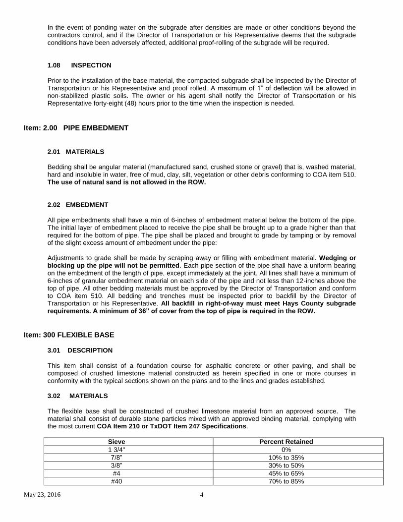
3.01 DESCRIPTION This item shall consist of a foundation course for asphaltic concrete or other paving, and shall be composed of crushed limestone material constructed as herein specified in one or more courses in conformity with the typical sections shown on the plans and to the lines and grades established. 3.02 MATERIALS The flexible base shall be constructed of crushed limestone material from an approved source. The material shall consist of durable stone particles mixed with an approved binding material, complying with the most current COA Item 210 or TxDOT Item 247 Specifications.
Sieve Percent Retained
1 3/4" 0%
7/8” 10% to 35%
3/8” 30% to 50%
#4 45% to 65%
#40 70% to 85%
May 23, 2016 5
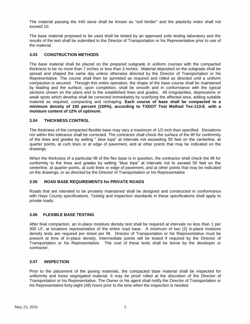
The material passing the #40 sieve shall be known as "soil binder" and the plasticity index shall not exceed 10. The base material proposed to be used shall be tested by an approved soils testing laboratory and the results of the test shall be submitted to the Director of Transportation or his Representative prior to use of the material. 3.03 CONSTRUCTION METHODS The base material shall be placed on the prepared subgrade in uniform courses with the compacted thickness to be no more than 7 inches or less than 3 inches. Material deposited on the subgrade shall be spread and shaped the same day unless otherwise directed by the Director of Transportation or his Representative. The course shall then be sprinkled as required and rolled as directed until a uniform compaction is secured. Through this entire operation, the shape of the base course shall be maintained by blading and the surface, upon completion, shall be smooth and in conformance with the typical sections shown on the plans and to the established lines and grades. All irregularities, depressions or weak spots which develop shall be corrected immediately by scarifying the affected area, adding suitable material as required, compacting and reshaping. Each course of base shall be compacted to a minimum density of 100 percent (100%), according to TXDOT Test Method Tex-113-E, with a moisture content of ±2% of optimum. 3.04 THICKNESS CONTROL The thickness of the compacted flexible base may vary a maximum of 1/2 inch than specified. Deviations not within this tolerance shall be corrected. The contractor shall check the surface of the lift for conformity of the lines and grades by setting “ blue tops” at intervals not exceeding 50 feet on the centerline, at quarter points, at curb lines or at edge of pavement, and at other points that may be indicated on the drawings. When the thickness of a particular lift of the flex base is in question, the contractor shall check the lift for conformity to the lines and grades by setting “blue tops” at intervals not to exceed 50 feet on the centerline, at quarter points, at curb lines or edge of pavement, and at other points that may be indicated on the drawings, or as directed by the Director of Transportation or his Representative 3.05 ROAD BASE REQUIREMENTS for PRIVATE ROADS Roads that are intended to be privately maintained shall be designed and constructed in conformance with Hays County specifications. Testing and inspection standards in these specifications shall apply to private roads.
3.06 FLEXIBLE BASE TESTING After final compaction, an in-place moisture density test shall be required at intervals no less than 1 per 300 LF, at locations representative of the entire road base. A minimum of two (2) in-place moisture density tests are required per street per lift. Director of Transportation or his Representative must be present at time of in-place density. Intermediate points will be tested if required by the Director of Transportation or his Representative. The cost of these tests shall be borne by the developer or contractor. 3.07 INSPECTION Prior to the placement of the paving materials, the compacted base material shall be inspected for uniformity and loose segregated material. It may be proof rolled at the discretion of the Director of Transportation or his Representative. The Owner or his agent shall notify the Director of Transportation or his Representative forty-eight (48) hours prior to the time when the inspection is needed.

May 23, 2016 6
Item: 4.00 PRIME COAT
4.01 DESCRIPTION
This item shall govern the application of asphaltic material on the completed base course and/or other approved areas in accordance with the Drawings, these specifications or as directed by the Director of Transportation or designated representative.
4.02 MATERIALS
The asphalt material for Prime Coat shall meet the requirements of Cutback Asphalt, MC-30, Emulsion, SS-1, Emulsion CSS-1 or AE-P, Standard Specification Item No. 301S, "Asphalts, Oils and Emulsions".
4.03 CONSTRUCTION METHODS
When, in the opinion of the Director of Transportation or his designated representative, the base course or other surface is ready to receive the prime coat, the surface shall be prepared by sweeping or other approved methods as directed by the Director of Transportation or designated representative. The surface shall be lightly sprinkled with water just prior to application of the asphaltic material unless this requirement is waived by the Director of Transportation or designated representative. The Contractor shall submit a list of prime material(s) recommended for application on the work to the Director of Transportation or designated representative for approval. When emulsions are approved, a dispersal agent shall be added to the water before application. The asphaltic material shall be applied on the clean surface by an approved type of self-propelled pressure distributor operated so as to distribute the prime coat at a rate ranging from 0.1 to 0.3 gallons per square yard (0.45 to 1.36 liters per square meter) of surface area. The material shall be evenly and smoothly distributed under pressure sufficient to assure proper distribution. During the application of prime coat, care shall be taken to prevent overspray of adjacent pavement, curb and gutters or structures. The Contractor shall be responsible for cleaning all areas contaminated by overspray. Prime Coat may be applied when the surface temperature is 60
°F or higher, and the air temperature is 50
°F and rising.
Measure the air temperature in the shade and away from artificial heat. Asphaltic material shall not be placed when general weather conditions, in the opinion of the Engineer or designated representative, are not suitable. The application of prime coat shall be prohibited when the forecast for precipitation is equal to or greater than 50% within 24 hours of the time of proposed application. The Contractor shall apply the asphaltic material at a
temperature within 15°F of the specified temperature, but not exceed the maximum allowable in most current TxDOT item
300 specifications. The Contractor shall provide all necessary equipment for determining the temperature of the asphaltic material, the rate at which it is applied, and for determining uniformity between two (2) distributor loads. The distributor shall have been calibrated within three (3) years from the date it is first used on this project. The Director of Transportation or designated representative shall be furnished an accurate and satisfactory record of such calibration upon request. After beginning the work, if the yield on the asphaltic material applied appears in error, the distributor shall be calibrated in a manner satisfactory to the Director of Transportation or designated representative before proceeding with the work. The Contractor shall be responsible for the maintenance of the surface until the work is accepted by the Engineer or designated representative. No traffic, hauling or placement of any subsequent courses shall be permitted over the freshly applied prime coat for a minimum of 24 hours or until the prime coat is accepted as dry and cured completely by the Director of Transportation or designated representative. All storage tanks, piping, retorts, booster tanks and distributors used in storing or handling asphaltic materials shall be kept clean and in good operating condition at all times and they shall be operated in such manner that there will be no contamination of the asphaltic material with foreign material. It shall be the responsibility of the Contractor to provide and maintain in good working order a recording thermometer at the material storage facility at all times.
In the event of rain prior to the placement of HMAC, the primed base shall be inspected and approved before proceeding with the next course.
May 23, 2016 7
Item: 5.00 TWO COURSE SURFACE TREATMENT
5.01 DESCRIPTION This item shall consist of a wearing surface composed of two applications of asphaltic material, each covered with aggregate constructed on the prepared base course as herein specified and in accordance with the details shown on the plans. All specifications in this item shall be in conformance with COA Item 320S. A two course surface treatment may be applied when the surface temperature is 60
°F or higher, and the
air temperature is 50°F and rising. Measure the air temperature in the shade and away from artificial heat.
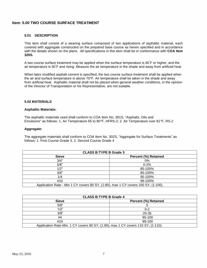
When latex modified asphalt cement is specified, the two course surface treatment shall be applied when the air and surface temperature is above 70°F. Air temperature shall be taken in the shade and away from artificial heat. Asphaltic material shall not be placed when general weather conditions, in the opinion of the Director of Transportation or his Representative, are not suitable. 5.02 MATERIALS Asphaltic Materials: The asphaltic materials used shall conform to COA Item No. 301S, "Asphalts, Oils and Emulsions" as follows: 1. Air Temperature 65 to 80°F, HFRS-2; 2. Air Temperature over 81°F, RS-2 Aggregate: The aggregate materials shall conform to COA Item No. 302S, "Aggregate for Surface Treatments" as follows: 1. First Course Grade 3, 2. Second Course Grade 4
CLASS B:TYPE B Grade 3
Sieve Percent (%) Retained
3/4" 0%
5/8” 0-2%
1/2" 85-100%
3/8” 85-100%
1/4 95-100%
#10 99-100%
Application Rate - Min 1 CY covers 80 SY, (1:80), max 1 CY covers 100 SY, (1:100).
CLASS B:TYPE B Grade 4
Sieve Percent (%) Retained
5/8” 0
1/2” 0-2
3/8” 20-35
#4 95-100
#10 99-100
Application Rate-Min. 1 CY covers 90 SY, (1:90); max 1 CY covers 110 SY, (1:110).
May 23, 2016 8
5.03 CONSTRUCTION METHODS The area to be treated shall be cleaned of dirt, dust, or other deleterious matter by sweeping or other approved methods. Asphaltic material of the type and grade shown on the plans for the first course shall be applied on the clean surface by an approved type of self-propelled pressure distributor so operated as to distribute the material in the quantity specified, evenly and smoothly, under a pressure necessary for proper distribution. The Contractor shall provide all necessary facilities for determining the temperature of the asphaltic material in all of the heating equipment and in the distributor, for determining the rate at which it is applied, and for securing uniformity at the junction of two distributor loads. The distributor shall have been recently calibrated and the Director of Transportation or his Representative shall be furnished an accurate and satisfactory record of such calibration. After beginning work, should the yield of the asphalt material appear to be in error, the distributor shall be recalibrated in a manner satisfactory to the Road Director before proceeding. Asphaltic material for each course may be applied for the full width of the surface treatment in one application, unless the width exceeds twenty-six feet (26'). No traffic or hauling will be permitted over the freshly applied asphaltic material until immediate covering is assured. Aggregate, of the type and grade shown on the plans for the first course, shall be immediately and uniformly applied and spread by an approved self-propelled continuous feed aggregate spreader, unless otherwise shown on the plans or authorized by the Director of Transportation in writing. The aggregate shall be applied at the approximate rates indicated on the plans and as directed by the Director of Transportation or his Representative. The Contractor shall be responsible for the maintenance of the surface of the first course until the second course is applied. The entire surface shall be broomed, bladed or raked as required by the Director of Transportation or his Representative and shall be thoroughly rolled with power rollers, self-propelled type, weighing not less than 6 tons not more than 12 tons. All wheels shall be flat. In lieu of the rolling equipment specified, the Contractor may, upon written permission from the Director of Transportation, operate other compacting equipment that will produce equivalent relative compaction in the same period of time as the specified equipment. If the substituted compaction equipment fails to produce the desired compaction within the same period as would be expected of the specified equipment, as determined by the Director of Transportation or his Representative, its use shall be discontinued. Rollers shall be maintained in good repair and operating condition and shall be approved by the Director of Transportation or his Representative. The second course shall consist of asphaltic material and aggregate of the type and grade indicated on the plans for the second course. The asphaltic material and aggregate for this second course shall be applied and covered in the manner specified for the first application. The surface shall then be broomed, bladed or raked as required by the Director of Transportation or his Representative and thoroughly rolled as specified for the first course. Asphaltic materials and aggregates for both courses shall be applied at the approximate rates indicated on the plans and as directed by the Director of Transportation or his Representative. The Contractor shall be responsible for the maintenance of the surface until the work is accepted by the Director of Transportation. The Contractor shall be responsible for the proper preparation of all stockpile area before aggregates are placed thereon, including leveling and cleaning of debris necessary for the protection of the aggregate to prevent any contamination thereof. All storage tanks, piping, retorts, booster tanks and distributors used in storing or handling asphaltic materials shall be kept clean and in good operating condition at all times and they shall be operated in such manner that there will be no contamination of the asphaltic material with foreign material. It shall be the responsibility of the Contractor to provide and maintain in good working order a recording thermometer at the material storage facility at all times.
May 23, 2016 9
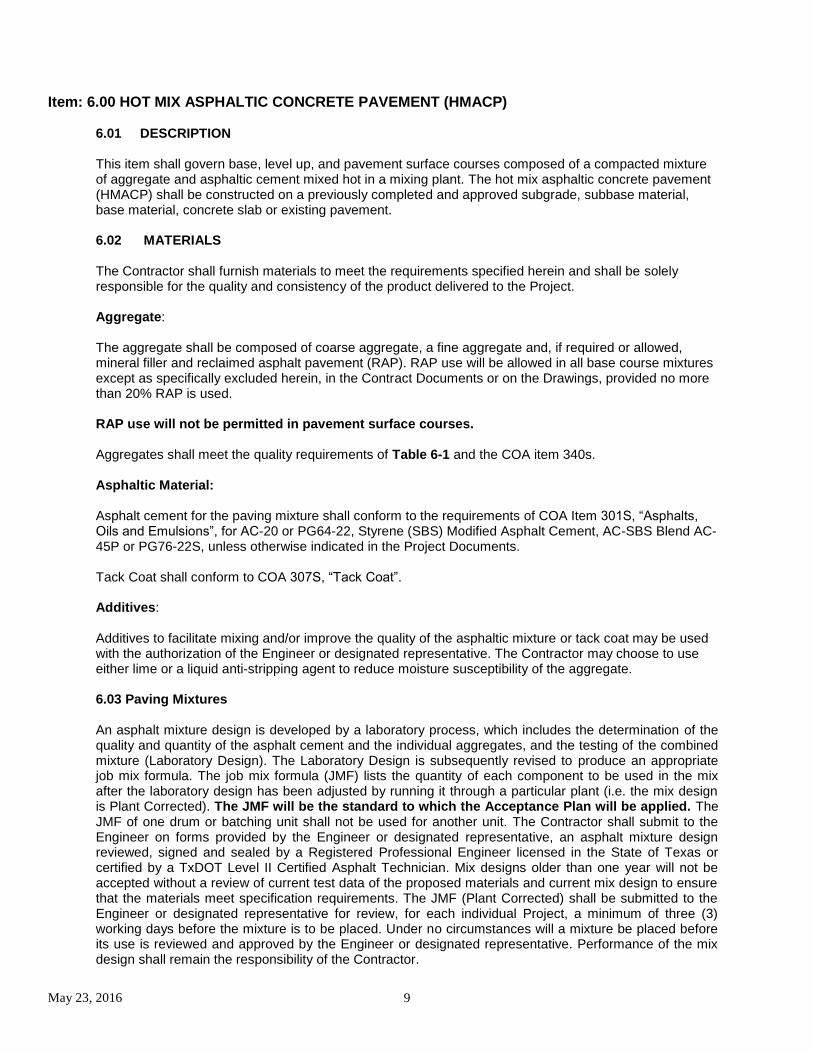
Item: 6.00 HOT MIX ASPHALTIC CONCRETE PAVEMENT (HMACP) 6.01 DESCRIPTION This item shall govern base, level up, and pavement surface courses composed of a compacted mixture of aggregate and asphaltic cement mixed hot in a mixing plant. The hot mix asphaltic concrete pavement (HMACP) shall be constructed on a previously completed and approved subgrade, subbase material, base material, concrete slab or existing pavement. 6.02 MATERIALS The Contractor shall furnish materials to meet the requirements specified herein and shall be solely responsible for the quality and consistency of the product delivered to the Project. Aggregate: The aggregate shall be composed of coarse aggregate, a fine aggregate and, if required or allowed, mineral filler and reclaimed asphalt pavement (RAP). RAP use will be allowed in all base course mixtures except as specifically excluded herein, in the Contract Documents or on the Drawings, provided no more than 20% RAP is used. RAP use will not be permitted in pavement surface courses. Aggregates shall meet the quality requirements of Table 6-1 and the COA item 340s. Asphaltic Material: Asphalt cement for the paving mixture shall conform to the requirements of COA Item 301S, “Asphalts, Oils and Emulsions”, for AC-20 or PG64-22, Styrene (SBS) Modified Asphalt Cement, AC-SBS Blend AC-45P or PG76-22S, unless otherwise indicated in the Project Documents. Tack Coat shall conform to COA 307S, “Tack Coat”. Additives: Additives to facilitate mixing and/or improve the quality of the asphaltic mixture or tack coat may be used with the authorization of the Engineer or designated representative. The Contractor may choose to use either lime or a liquid anti-stripping agent to reduce moisture susceptibility of the aggregate. 6.03 Paving Mixtures An asphalt mixture design is developed by a laboratory process, which includes the determination of the quality and quantity of the asphalt cement and the individual aggregates, and the testing of the combined mixture (Laboratory Design). The Laboratory Design is subsequently revised to produce an appropriate job mix formula. The job mix formula (JMF) lists the quantity of each component to be used in the mix after the laboratory design has been adjusted by running it through a particular plant (i.e. the mix design is Plant Corrected). The JMF will be the standard to which the Acceptance Plan will be applied. The JMF of one drum or batching unit shall not be used for another unit. The Contractor shall submit to the Engineer on forms provided by the Engineer or designated representative, an asphalt mixture design reviewed, signed and sealed by a Registered Professional Engineer licensed in the State of Texas or certified by a TxDOT Level II Certified Asphalt Technician. Mix designs older than one year will not be accepted without a review of current test data of the proposed materials and current mix design to ensure that the materials meet specification requirements. The JMF (Plant Corrected) shall be submitted to the Engineer or designated representative for review, for each individual Project, a minimum of three (3) working days before the mixture is to be placed. Under no circumstances will a mixture be placed before its use is reviewed and approved by the Engineer or designated representative. Performance of the mix design shall remain the responsibility of the Contractor.

May 23, 2016 10
Mixture Design: The mix shall be an approved TxDOT design and comply with Construction Bulletin C-14 and Test Method Tex-204-F and the requirements herein. The master grading limits of the appropriate type and the JMF will be plotted on a graduated chart with sieve sizes raised to the 0.45 power and will be submitted to the Engineer or designated representative with the asphalt mixture design. The Bulk Specific Gravity of aggregates in RAP will be determined on extracted aggregates. Types: The blend of coarse aggregate, fine aggregate, and mineral filler, if allowed, that is established by TxDOT Test Method Tex-200-F, Dry Sieve Analysis, shall conform to the master gradation shown in Table 6-1 for the type of specified mixture. The voids in the mineral aggregate (VMA) will be determined as a mixture design requirement only, in accordance with TxDOT Test Method Tex-207-F, and shall not be less than the value indicated in Table 6-1.
TABLE 6-1: Master Grading - Percent Passing by Weight (Mass) or Volume
Sieve Size US (SI)
Type C Coarse Surface
Type D Fine Surface
7/8” (22 mm) 100
5/8” (15.5 mm) 95-100
1/2” (12.5 mm) 100
3/8” (9.5 mm) 70-85 85-100
No. 4 (4.75 mm) 43-63 50-70
No. 10 (2.00 mm) 30-40 32-42
No. 40 (425 μm) 10-25 11-26
No. 80 (187.5 μm) 3-13 4-14
No. 200 (75 μm) 1-6 1-6
VMA % minimum 13 14
Rec. Min. Lift 2” (50 mm) 1-1/2” (37.5 mm)
Tolerances: Fluctuations in the aggregate gradation and asphalt content of the Job Mix Formula (JMF) shall not vary by more than the following criteria but the aggregate gradation shall be limited to the range of the master gradation as established by TEX-210-F.
SIEVES Percent By Weight
(Mass)
2" (50 mm) Sieve through No. 10 (2.00 mm) Sieve No. 40 (425 μm) through No. 200 (75 μm) Sieve Asphalt Content
5.0 3.0 0.5
Stability and Density: The mixture shall be designed at or near optimum density, as indicated on the Drawings, to conform to the following percent of Maximum theoretical Density as measured by TxDOT Test Method TEX-227-F and Stability conforming to TxDOT Test Method TEX-208-F. The laboratory mixture shall be molded in accordance with TxDOT Test Method TEX-206-F and the Bulk Specific Gravity determined in accordance with TxDOT Test Method TEX-207-F.
Surface Courses
Optimum Laboratory
Density
Laboratory Density
Stability Min Max
Lanes/Local Streets 96% 94.5% 97.5% 35 min
Collectors/Arterials 96% 94.5% 97.5% 40-60 min
May 23, 2016 11
6.04 Equipment
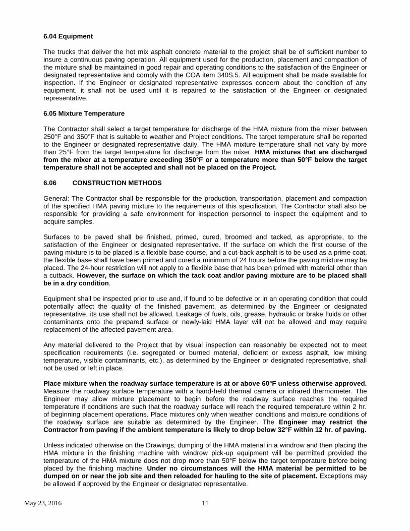
The trucks that deliver the hot mix asphalt concrete material to the project shall be of sufficient number to insure a continuous paving operation. All equipment used for the production, placement and compaction of the mixture shall be maintained in good repair and operating conditions to the satisfaction of the Engineer or designated representative and comply with the COA item 340S.5. All equipment shall be made available for inspection. If the Engineer or designated representative expresses concern about the condition of any equipment, it shall not be used until it is repaired to the satisfaction of the Engineer or designated representative. 6.05 Mixture Temperature The Contractor shall select a target temperature for discharge of the HMA mixture from the mixer between 250°F and 350°F that is suitable to weather and Project conditions. The target temperature shall be reported to the Engineer or designated representative daily. The HMA mixture temperature shall not vary by more than 25°F from the target temperature for discharge from the mixer. HMA mixtures that are discharged from the mixer at a temperature exceeding 350°F or a temperature more than 50°F below the target temperature shall not be accepted and shall not be placed on the Project.
6.06 CONSTRUCTION METHODS
General: The Contractor shall be responsible for the production, transportation, placement and compaction of the specified HMA paving mixture to the requirements of this specification. The Contractor shall also be responsible for providing a safe environment for inspection personnel to inspect the equipment and to acquire samples. Surfaces to be paved shall be finished, primed, cured, broomed and tacked, as appropriate, to the satisfaction of the Engineer or designated representative. If the surface on which the first course of the paving mixture is to be placed is a flexible base course, and a cut-back asphalt is to be used as a prime coat, the flexible base shall have been primed and cured a minimum of 24 hours before the paving mixture may be placed. The 24-hour restriction will not apply to a flexible base that has been primed with material other than a cutback. However, the surface on which the tack coat and/or paving mixture are to be placed shall be in a dry condition. Equipment shall be inspected prior to use and, if found to be defective or in an operating condition that could potentially affect the quality of the finished pavement, as determined by the Engineer or designated representative, its use shall not be allowed. Leakage of fuels, oils, grease, hydraulic or brake fluids or other contaminants onto the prepared surface or newly-laid HMA layer will not be allowed and may require replacement of the affected pavement area. Any material delivered to the Project that by visual inspection can reasonably be expected not to meet specification requirements (i.e. segregated or burned material, deficient or excess asphalt, low mixing temperature, visible contaminants, etc.), as determined by the Engineer or designated representative, shall not be used or left in place. Place mixture when the roadway surface temperature is at or above 60°F unless otherwise approved. Measure the roadway surface temperature with a hand-held thermal camera or infrared thermometer. The Engineer may allow mixture placement to begin before the roadway surface reaches the required temperature if conditions are such that the roadway surface will reach the required temperature within 2 hr. of beginning placement operations. Place mixtures only when weather conditions and moisture conditions of the roadway surface are suitable as determined by the Engineer. The Engineer may restrict the Contractor from paving if the ambient temperature is likely to drop below 32°F within 12 hr. of paving. Unless indicated otherwise on the Drawings, dumping of the HMA material in a windrow and then placing the HMA mixture in the finishing machine with windrow pick-up equipment will be permitted provided the temperature of the HMA mixture does not drop more than 50°F below the target temperature before being placed by the finishing machine. Under no circumstances will the HMA material be permitted to be dumped on or near the job site and then reloaded for hauling to the site of placement. Exceptions may be allowed if approved by the Engineer or designated representative.
May 23, 2016 12
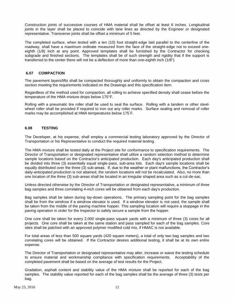
Construction joints of successive courses of HMA material shall be offset at least 6 inches. Longitudinal joints in the layer shall be placed to coincide with lane lines as directed by the Engineer or designated representative. Transverse joints shall be offset a minimum of 5 feet. The completed surface, when tested with a ten (10) foot straight-edge laid parallel to the centerline of the roadway, shall have a maximum ordinate measured from the face of the straight-edge not to exceed one-eighth (1/8) inch at any point. Approved templates shall be furnished by the Contractor for checking subgrade and finished sections. The templates shall be of such strength and rigidity that if the support is transferred to the center there will not be a deflection of more than one-eighth inch (1/8"). 6.07 COMPACTION
The pavement layers/lifts shall be compacted thoroughly and uniformly to obtain the compaction and cross section meeting the requirements indicated on the Drawings and this specification item.
Regardless of the method used for compaction, all rolling to achieve specified density shall cease before the temperature of the HMA mixture drops below 175°F.
Rolling with a pneumatic tire roller shall be used to seal the surface. Rolling with a tandem or other steel-wheel roller shall be provided if required to iron out any roller marks. Surface sealing and removal of roller marks may be accomplished at HMA temperatures below 175
°F.
6.08 TESTING The Developer, at his expense, shall employ a commercial testing laboratory approved by the Director of Transportation or his Representative to conduct the required material testing. The HMA mixture shall be tested daily at the Project site for conformance to specification requirements. The Director of Transportation or designated representative shall utilize a random selection method to determine sample locations based on the Contractor's anticipated production. Each day's anticipated production shall be divided into three (3) essentially equal single-pass, sub-area lots. Each day's sample locations shall be equally distributed over the three (3) sub-areas. If, due to the weather or plant malfunctions, the Contractor’s daily-anticipated production is not attained, the random locations will not be recalculated. Also, no more than one location of the three (3) sub-areas shall be located in an irregular shaped area such as a cul-de-sac.
Unless directed otherwise by the Director of Transportation or designated representative, a minimum of three bag samples and three correlating 4-inch cores will be obtained from each day's production.
Bag samples shall be taken during lay-down operations. The primary sampling point for the bag samples shall be from the windrow if a windrow elevator is used. If a windrow elevator is not used, the sample shall be taken from the middle of the paving machine hopper. This sampling location will require a stoppage in the paving operation in order for the Inspector to safely secure a sample from the hopper.
One core shall be taken for every 2,000 single-pass square yards with a minimum of three (3) cores for all projects. One core shall be taken at the same station and pass sampled for each of the bag samples. Core sites shall be patched with an approved polymer modified cold mix, if HMAC is not available.
For total areas of less than 500 square yards (420 square meters), a total of only two bag samples and two correlating cores will be obtained. If the Contractor desires additional testing, it shall be at its own entire expense.
The Director of Transportation or designated representative may alter, increase or waive the testing schedule to ensure material and workmanship compliance with specification requirements. Acceptability of the completed pavement shall be based on the average of test results for the Project.
Gradation, asphalt content and stability value of the HMA mixture shall be reported for each of the bag samples. The stability value reported for each of the bag samples shall be the average of three (3) tests per bag.

May 23, 2016 13
Pavement thickness and density shall be determined from 4-inch field cores. For each day's placement, density of cores for which no corresponding bag samples were taken shall be determined by using the average Maximum Theoretical Density of the day's three (3) bag samples or as may otherwise be determined by the Director of Transportation or designated representative.
An HMAC thickness of 1.5” shall be the minimum at any and all locations, rather than an average.
When, in the opinion of the Director of Transportation or designated representative, test results appear unrepresentative, additional testing may be authorized. The retesting will be at the expense of the Owner and the results of the retesting shall be averaged with the results of the original testing. If the results of retesting indicate that the original test results were erroneous, the original test results will be discarded.
6.09 ASPHALT CONTENT ACCEPTANCE SCHEDULE
% Deviation from the JMF All Roadways
≤ +/- 0.3 Acceptance
+/- 0.31 to +/- 0.50 +2 year Warranty
> +/- 0.50 1” Overlay
6.10 DENSITY ACCEPTANCE SCHEDULE
Average Percent Density All Roadways
˃ 96 1” Overlay
91 to 96 Acceptance
˂ 91 1” Overlay
6.11 THICKNESS ACCEPTANCE SCHEDULE
Variance Percent of Thickness 2” thickness or Greater
0 – 10 Acceptance
10.1 - 16 +2 year Warranty
˃16 1” Overlay
*Note - a 1” Overlay shall be required if HMAC is deficient in more than one category.
Item: 7.00 REINFORCING STEEL
7.01 Description
This item shall consist of the furnishing and placing of reinforcing steel, deformed and smooth, of the size and quantity indicated and in accordance with COA item 406S.
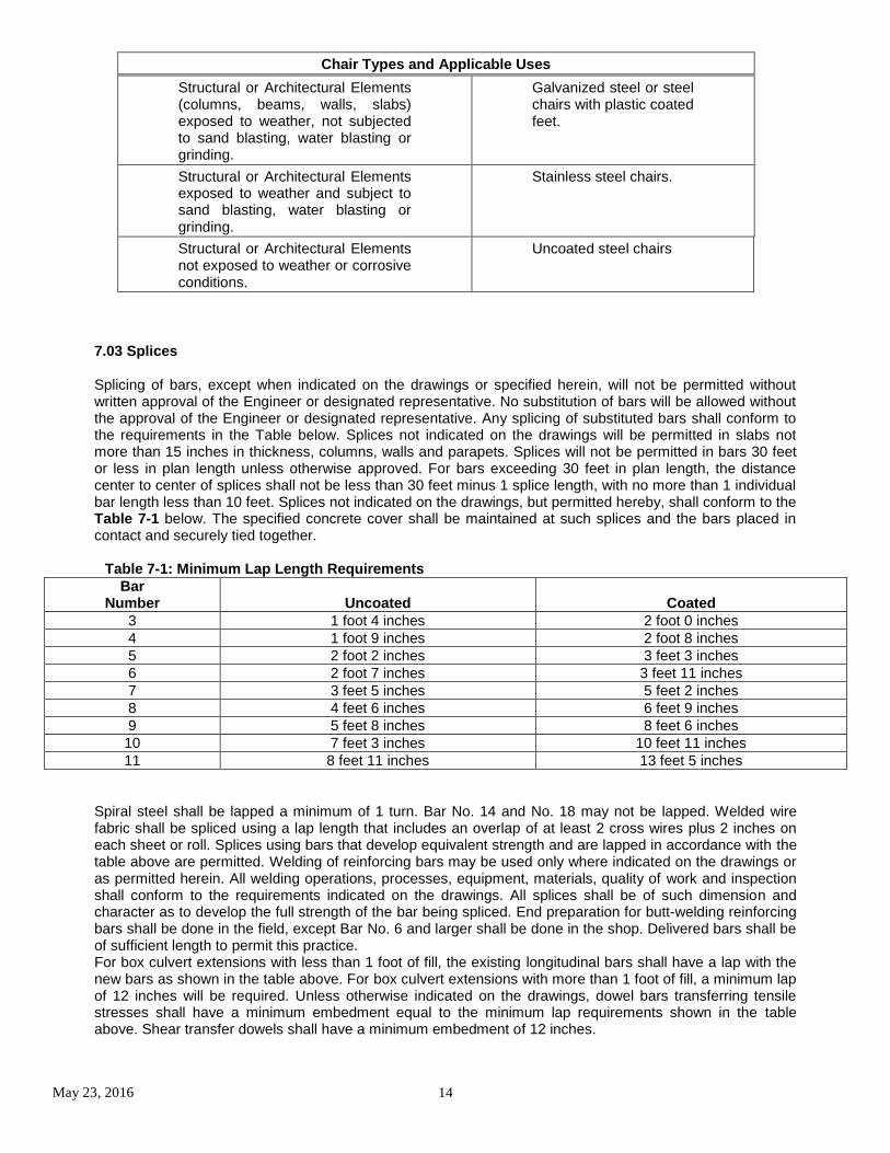
7.02 Chairs and Supports
Chairs and Supports shall be steel, precast mortar or concrete blocks cast in molds meeting the approval of the Engineer/Architect of sufficient strength to position the reinforcement as indicated when supporting the dead load of the reinforcement, the weight of the workers placing concrete and the weight of the concrete bearing on the steel. Chairs shall be plastic coated when indicated.
May 23, 2016 14
Chair Types and Applicable Uses
Structural or Architectural Elements (columns, beams, walls, slabs) exposed to weather, not subjected to sand blasting, water blasting or grinding.
Galvanized steel or steel chairs with plastic coated feet.
Structural or Architectural Elements exposed to weather and subject to sand blasting, water blasting or grinding.
Stainless steel chairs.
Structural or Architectural Elements not exposed to weather or corrosive conditions.
Uncoated steel chairs
7.03 Splices Splicing of bars, except when indicated on the drawings or specified herein, will not be permitted without written approval of the Engineer or designated representative. No substitution of bars will be allowed without the approval of the Engineer or designated representative. Any splicing of substituted bars shall conform to the requirements in the Table below. Splices not indicated on the drawings will be permitted in slabs not more than 15 inches in thickness, columns, walls and parapets. Splices will not be permitted in bars 30 feet or less in plan length unless otherwise approved. For bars exceeding 30 feet in plan length, the distance center to center of splices shall not be less than 30 feet minus 1 splice length, with no more than 1 individual bar length less than 10 feet. Splices not indicated on the drawings, but permitted hereby, shall conform to the Table 7-1 below. The specified concrete cover shall be maintained at such splices and the bars placed in contact and securely tied together.
Table 7-1: Minimum Lap Length Requirements
Bar Number Uncoated Coated
3 1 foot 4 inches 2 foot 0 inches
4 1 foot 9 inches 2 foot 8 inches
5 2 foot 2 inches 3 feet 3 inches
6 2 foot 7 inches 3 feet 11 inches
7 3 feet 5 inches 5 feet 2 inches
8 4 feet 6 inches 6 feet 9 inches
9 5 feet 8 inches 8 feet 6 inches
10 7 feet 3 inches 10 feet 11 inches
11 8 feet 11 inches 13 feet 5 inches
Spiral steel shall be lapped a minimum of 1 turn. Bar No. 14 and No. 18 may not be lapped. Welded wire fabric shall be spliced using a lap length that includes an overlap of at least 2 cross wires plus 2 inches on each sheet or roll. Splices using bars that develop equivalent strength and are lapped in accordance with the table above are permitted. Welding of reinforcing bars may be used only where indicated on the drawings or as permitted herein. All welding operations, processes, equipment, materials, quality of work and inspection shall conform to the requirements indicated on the drawings. All splices shall be of such dimension and character as to develop the full strength of the bar being spliced. End preparation for butt-welding reinforcing bars shall be done in the field, except Bar No. 6 and larger shall be done in the shop. Delivered bars shall be of sufficient length to permit this practice. For box culvert extensions with less than 1 foot of fill, the existing longitudinal bars shall have a lap with the new bars as shown in the table above. For box culvert extensions with more than 1 foot of fill, a minimum lap of 12 inches will be required. Unless otherwise indicated on the drawings, dowel bars transferring tensile stresses shall have a minimum embedment equal to the minimum lap requirements shown in the table above. Shear transfer dowels shall have a minimum embedment of 12 inches.
May 23, 2016 15
7.04 Placement All reinforcing steel shall be tied at all intersections, except that where spacing is less than 1 foot in each direction, alternate intersections only need be tied. For reinforcing steel cages for other structural members, the steel shall be tied at enough intersections to provide a rigid cage of steel. Mats of wire fabric shall overlap each other 1 full space as a minimum to maintain a uniform strength and shall be tied at the ends and edges. Where prefabricated deformed wire mats are specified or if the Contractor requests, welded wire fabric may be substituted for a comparable area of steel reinforcing bar plan, subject to the approval of the Engineer/Architect.
A suitable tie wire shall be provided in each block, to be used for anchoring to the steel. Except in unusual cases and when specifically authorized by the Engineer, the size of the surface to be placed adjacent to the forms shall not exceed 2 1/2 inches square or the equivalent thereof in cases where circular or rectangular areas are provided. Blocks shall be cast accurately to the thickness required and the surface to be placed adjacent to the forms shall be a true plane, free of surface imperfections.
Reinforcement shall be supported and tied in such a manner that a sufficiently rigid cage of steel is provided. If the cage is not adequately supported to resist settlement or floating upward of the steel, overturning of truss bars or movement in any direction during concrete placement, permission to continue concrete placement will be withheld until corrective measures are taken. Sufficient measurements shall be made during concrete placement to insure compliance with the above.
No concrete shall be deposited until the Engineer/Architect has reviewed the placement of the reinforcing steel and all mortar, mud, dirt, etc., shall be cleaned from the reinforcement, forms, workers' boots and tools.
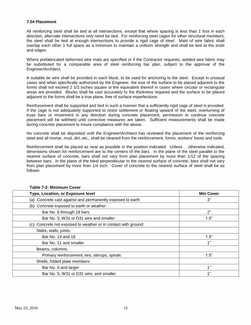
Reinforcement shall be placed as near as possible in the position indicated. Unless otherwise indicated, dimensions shown for reinforcement are to the centers of the bars. In the plane of the steel parallel to the nearest surface of concrete, bars shall not vary from plan placement by more than 1/12 of the spacing between bars. In the plane of the steel perpendicular to the nearest surface of concrete, bars shall not vary from plan placement by more than 1/4 inch. Cover of concrete to the nearest surface of steel shall be as follows:
Table 7-2: Minimum Cover
Type, Location, or Exposure level Min Cover
(a) Concrete cast against and permanently exposed to earth 3”
(b) Concrete exposed to earth or weather:
Bar No. 6 through 18 bars 2”
Bar No. 5, W31 or D31 wire and smaller 1.5”
(c) Concrete not exposed to weather or in contact with ground:
Slabs, walls, joists:
Bar No. 14 and 18 1.5”
Bar No. 11 and smaller 1”
Beams, columns:
Primary reinforcement, ties, stirrups, spirals 1.5”
Shells, folded plate members:
Bar No. 6 and larger 1”
Bar No. 5, W31 or D31 wire, and smaller 1”
May 23, 2016 16
Item: 8.00 CONCRETE for STRUCTURES
8.01 Description This item shall govern quality, storage, handling, proportioning and mixing of materials for Portland cement concrete construction of bridges, culverts, slabs, prestressed concrete and incidental appurtenances.
8.02 Materials
Concrete shall be composed of Portland cement or Portland cement and fly ash, water, aggregates (fine and coarse), and admixtures proportioned and mixed as hereinafter provided to achieve specified results.
A. Cementitious Materials: Portland cement shall conform to ASTM C 150 and COA item 403S, Type I (General Purpose), Type II (General Purpose with Moderate Sulfate Resistance) and Type III (High Early Strength). Type I shall be used when none is specified or indicated on the drawings. Type I and Type III cements shall not be used when Type II cement is specified or indicated on the drawings. Type III cement may be used in lieu of a Type I cement, when the anticipated air temperature for the succeeding 12 hours will not exceed 60
°F. All cement shall be of the same type
and from the same source for a monolithic placement.
B. Mixing Water: Water for use in concrete and for curing shall be potable water free of oils, acids, organic matter or other deleterious substances and shall not contain more than 1,000 parts per million of chlorides as Cl or sulfates as SO4.
C. Mortar and Grout: Unless otherwise specified, indicated on the drawings or approved by the Engineer or designated representative mortar and grout shall consist of 1 part cement, 2 parts finely graded sand and enough water to make the mixture plastic. When required to prevent color difference, white cement shall be added to produce color required. When required by the Engineer or designated representative, an approved latex adhesive may be added to the mortar.
D. Admixtures: All chemical admixtures including water reducing, plasticizers and air entrainment shall conform to TxDOT DMS-4640, “Chemical Admixtures for Concrete”. Calcium chloride-based admixtures shall not be approved. Admixtures shall be included in the prequalified concrete admixtures list maintained by TxDOT’s Construction Division. High-range water-reducing admixtures (TxDOT Type F or G) and accelerating admixtures (TxDOT Type C or E) shall not be used in bridge deck concrete.
E. Air Entrainment Unless indicated otherwise on the drawings, all concrete classes with the exception of Class B shall be air entrained in accordance with Table 8-2. If the air content is more than 1.5 percentage points below or 3 percentage points above the required air, the load of concrete will be rejected. If the air content is more than 1.5 but less than 3 percentage points above the required air, the concrete may be accepted based on strength test results.
8.03 Mix Design The Contractor shall furnish a mix design acceptable to the Director of Transportation or designated representative for the class of concrete specified. The mix shall be designed by a qualified commercial laboratory and signed/sealed by a registered Professional Engineer, licensed in the state of Texas to conform with requirements contained herein, to ACI 211.1 or TXDOT Bulletin C-11 (and supplements thereto). The Contractor shall perform, at his own expense, the work required to substantiate the design, including testing of strength specimens. Complete concrete design data shall be submitted to the Director of Transportation or designated representative for approval. The mix design will be valid for a period of one (1) year provided that there are no changes to the component materials.
May 23, 2016 17
At the end of one (1) year, a previously approved mix may be resubmitted for approval if it can be shown that no substantial change in the component materials has occurred. The resubmittal analysis must be reviewed, signed and sealed by a registered Professional Engineer, licensed in the state of Texas.
This resubmittal shall include a reanalysis of specific gravity, absorption, fineness modulus, sand equivalent, soundness, wear, and unit weights of the aggregates. Provided that the fineness modulus did not deviate by more than 0.20 or that the re-proportioned total mixing water, aggregate and cement (or cement plus fly ash) are within 1, 2, and 3 percent, respectively, of pre-approved quantities, a one-year extension on the approval of the mix may be granted by the Engineer or designated representative. Updated cement, fly ash, and admixture certifications shall accompany the resubmittal.
8.04 Consistency and Quality of Concrete
Concrete shall be workable, cohesive, possess satisfactory finishing qualities and of stiffest consistency that can be placed and vibrated into a homogeneous mass within slump requirements specified in Table 8-3. No concrete will be permitted with a slump in excess of the maximums shown unless water-reducing admixtures have been previously approved. Slump values shall be conducted in accordance with TXDOT Test Method TEX-415-A.
Consistency and quality of concrete should allow efficient placement and completion of finishing operations before initial set. Re-tempering (i.e. addition of water and reworking concrete after initial set) shall not be allowed. When field conditions are such that additional moisture is needed for final concrete surface finishing operation, the required water shall be applied to surface by fog spray only and shall be held to a minimum. Excessive bleeding shall be avoided and in no case will it be permissible to expedite finishing and drying by the application of cement powder to the surface. During progress of the work, the Director of Transportation or designated representative shall require the Developer to cast test cylinders and/or beams as a check on compressive and/or flexural strength of concrete actually placed. The Director of Transportation or designated representative may require the developer also to perform slump tests, entrained air tests and temperature checks to ensure compliance with specifications. The cost shall be bared by the developer or contractor.
Unless otherwise specified or indicated on the drawings, concrete mix temperature shall not exceed 90°F except in mixes with high range water reducers where a maximum mix temperature of 100°F will be allowed. Cooling an otherwise acceptable mix by addition of water or ice during agitation will not be allowed.
Ice may be used during hot weather concrete placement to lower the concrete temperature; however, the Contractor shall furnish a mix design acceptable to the Engineer or designated representative for class of concrete specified. The addition of ice shall not exceed 50% of the total mix water weight.
Test cylinders may be required for small placements such as wing walls and head walls. The Engineer may vary the number of tests to a minimum of 1 for each 25 cubic yards placed over a several day period.
Slump tests will be performed in accordance with TxDOT Test Method Tex-415-A. Entrained air tests will be performed in accordance with TxDOT Test Method Tex-416-A.
Test specimens shall be cured using the same methods and under the same conditions as the concrete represented. Design strength beams and cylinders shall be cured conforming to TXDOT Bulletin C-11 (and supplements thereto).
When control of concrete quality is by 28-day compressive tests, job control testing will be by 7-day compressive strength tests. The minimum strength requirement for seven (7) day test will be 70 percent of the specified minimum 28-day compressive strength. If the required 7-day strength is not secured with the quantity of cement specified in Table 8-1, changes in the mix design shall be made and resubmitted for approval. For an occasional failure of the seven-day compressive test, the concrete may be tested at 28 days for final evaluation.
May 23, 2016 18
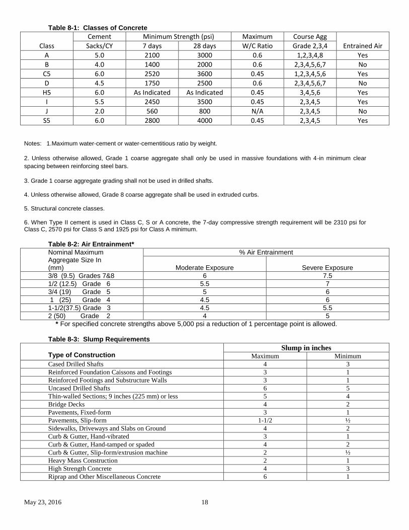
Table 8-1: Classes of Concrete
Class
Cement Minimum Strength (psi) Maximum Course Agg
Entrained Air Sacks/CY 7 days 28 days W/C Ratio Grade 2,3,4
A 5.0 2100 3000 0.6 1,2,3,4,8 Yes
B 4.0 1400 2000 0.6 2,3,4,5,6,7 No
C5 6.0 2520 3600 0.45 1,2,3,4,5,6 Yes
D 4.5 1750 2500 0.6 2,3,4,5,6,7 No
H5 6.0 As Indicated As Indicated 0.45 3,4,5,6 Yes
I 5.5 2450 3500 0.45 2,3,4,5 Yes
J 2.0 560 800 N/A 2,3,4,5 No
S5 6.0 2800 4000 0.45 2,3,4,5 Yes
Notes: 1.Maximum water-cement or water-cementitious ratio by weight.
2. Unless otherwise allowed, Grade 1 coarse aggregate shall only be used in massive foundations with 4-in minimum clear
spacing between reinforcing steel bars.
3. Grade 1 coarse aggregate grading shall not be used in drilled shafts.
4. Unless otherwise allowed, Grade 8 coarse aggregate shall be used in extruded curbs.
5. Structural concrete classes.
6. When Type II cement is used in Class C, S or A concrete, the 7-day compressive strength requirement will be 2310 psi for Class C, 2570 psi for Class S and 1925 psi for Class A minimum.
Table 8-2: Air Entrainment*
Nominal Maximum Aggregate Size In (mm)
% Air Entrainment
Moderate Exposure Severe Exposure
3/8 (9.5) Grades 7&8 6 7.5
1/2 (12.5) Grade 6 5.5 7
3/4 (19) Grade 5 5 6
1 (25) Grade 4 4.5 6
1-1/2(37.5) Grade 3 4.5 5.5
2 (50) Grade 2 4 5
* For specified concrete strengths above 5,000 psi a reduction of 1 percentage point is allowed. Table 8-3: Slump Requirements
Type of Construction
Slump in inches
Maximum Minimum
Cased Drilled Shafts 4 3
Reinforced Foundation Caissons and Footings 3 1
Reinforced Footings and Substructure Walls 3 1
Uncased Drilled Shafts 6 5
Thin-walled Sections; 9 inches (225 mm) or less 5 4
Bridge Decks 4 2
Pavements, Fixed-form 3 1
Pavements, Slip-form 1-1/2 ½
Sidewalks, Driveways and Slabs on Ground 4 2
Curb & Gutter, Hand-vibrated 3 1
Curb & Gutter, Hand-tamped or spaded 4 2
Curb & Gutter, Slip-form/extrusion machine 2 ½
Heavy Mass Construction 2 1
High Strength Concrete 4 3
Riprap and Other Miscellaneous Concrete 6 1
May 23, 2016 19
8.05 Mixing and Mixing Equipment
A. Ready-mixed Concrete
Use of ready-mixed concrete will be permitted provided the batching plant and mixer trucks meet quality requirements specified herein. When ready-mixed concrete is used, additional mortar (1 sack cement, 3 parts sand and sufficient water) shall be added to each batch to coat the mixer drum. Ready-mixed concrete, batching plant and mixer truck operation shall include the following:
1. A ticket system will be used that includes a copy for the Inspector. Ticket will have machine stamped time/date of concrete batch, a mix design designation, weight of cement, fly ash, sand and aggregates; exact nomenclature and written quantities of admixtures and water. Any item missing or incomplete on ticket may be cause for rejection of concrete.
2. Sufficient trucks will be available to support continuous placements. The Contractor will satisfy the Director of Transportation or designated representative that adequate standby trucks are available to support monolithic concrete placement requirements.
3. A portion of mixing water required by the mix design to produce the specified slump may be withheld and added at the job site, but only with permission of the Director of Transportation or designated representative and under the Inspector's observation. When water is added under these conditions, the concrete batch will be thoroughly mixed before any slump or strength samples are taken. Additional cement shall not be added at the job site to otherwise unacceptable mixes.
4. A metal plate(s) shall be attached in a prominent place on each truck mixer plainly showing the various uses for which it was designed. The data shall include the drum's speed of rotation for mixing and for agitating and the capacity for complete mixing and/or agitating only. A copy of the manufacturer's design, showing dimensions of blades, shall be available for inspection at the plant at all times. Accumulations of hardened concrete shall be removed to the satisfaction of the Director of Transportation or designated representative.
5. The loading of the transit mixers shall not exceed capacity as shown on the manufacturer's plate
attached to the mixer or 63 percent of the drum volume, whichever is the lesser volume. The loading of
transit mixers to the extent of causing spill-out en route to delivery will not be acceptable. Consistent spillage will be cause for disqualification of a supplier.
6. Excess concrete remaining in the drum after delivery and wash water after delivery shall not be dumped on the project site unless approval of the dump location is first secured from the Director of Transportation or designated representative.
B. Hand-mixed Concrete
Hand mixing of concrete may be permitted for small placements or in case of an emergency and then only on authorization of the Director of Transportation or designated representative. Hand-mixed batches shall not exceed a 4 cubic foot (3 cubic meters) batch in volume. Material volume ratios shall not be leaner than 1 part cement, 2 parts large aggregate, 1 part fine aggregate and enough water to produce a consistent mix with a slump not to exceed 4 inches. Admixtures shall not be used unless specifically approved by the Director of Transportation or designated representative.
Item: 9.00 DRAINAGE FACILITIES
9.01 DESCRIPTION This item shall govern the furnishing of all drainage culvert pipe, concrete headwalls, and reflector post as shown on the Plans and herein specified, and installing the same as designated on the Plans or by the Director of Transportation or his Representative in conformity with the lines and grades given.
May 23, 2016 20
9.02 MATERIALS The culvert pipe shall be of size, length, and gauge as shown on the plans. Corrugated galvanized metal pipe shall be as specified by item 460 of the most current TxDOT Standard Specifications. Reinforced concrete pipe shall be as specified by Item 464 of the same. All pipe shall be new and unused and shall not have been damaged by handling or shipping. Reflector posts shall conform to the COA detail 824-2 or an approved alternative, equipped with 3 inch amber reflectors. The length of the post shall be adequate to place the reflector assembly 48 inches above the centerline elevation of the street and anchor the post approximately 48 inches into the ground. Concrete headwalls and/or rip-rap shall be constructed of Class A concrete conforming with COA Item 403S reinforced with deformed bars or wire mesh conforming with Item 406S of same. All headwalls and/or rip-rap shall be of the dimensions and in the locations shown on the plans. 9.03 CONSTRUCTION METHODS Culvert pipe shall be installed to the lines and grades shown on the Plan or as specified by the Director of Transportation or his Representative. The pipe shall be bedded along its complete length and up to the shoulders. The backfill around the pipe shall be compacted. The installation of all culvert pipes shall be in general conformance with the appropriate sections of the most current TxDOT Standard Specifications. All culvert pipes located at street intersections shall be provided with reflector posts. The reflector post shall be equipped with one reflector facing in each direction of traffic flow. Reflector posts shall be provided on the ends of the concrete headwalls or rip-rap as shown on the Plans. The concrete headwalls or rip-rap shall be of the dimensions and at the locations shown on the plans. The headwalls shall be formed on their exposed surfaces, which shall be grouted and broom finished upon removal of the forms. Guardrail is required were slopes do not meet requirements of Table 7.3.
Item: 10.00 CHANNEL EXCAVATION
10.01 DESCRIPTION Channel Excavation shall consist of required excavation for all channels, the removal and proper utilization or disposal of all excavated materials, and constructing, shaping and finishing of all earthwork involved in conformity with the required lines, grades and typical cross sections and in accordance with the specifications and requirements herein outlined. 10.02 CLASSIFICATION All Channel Excavation will be Unclassified. Unclassified Channel Excavation shall include all materials encountered regardless of their nature or the manner in which they are removed. 10.03 CONSTRUCTION METHODS All suitable materials removed from the excavation shall be used, insofar as practicable, in the formation of embankments as required, or shall be otherwise utilized or satisfactorily disposed of as indicated on plans, or as directed, and completed work shall conform to the established alignment, grades and cross sections. During construction, the channel shall be kept drained, insofar as practicable, and the work shall be prosecuted in a neat and workmanlike manner. Unsuitable channel excavation or excavation in excess of that needed for construction, shall be known as "Waste" and shall become the property of the Contractor to be disposed of by him. Channel Excavation shall include the removal and replacement of all fence lines crossing the channels and the installation of gates and water gaps as shown on the plans. All channels and that area adjacent to them which has been disturbed by construction equipment shall be graded smooth and seeded. Seeding shall conform to item 164 of the most current TxDOT Standard Specifications or applicable standards for the appropriate jurisdiction.
May 23, 2016 21
Item: 11.00 CLEAR ZONES
11.01 General
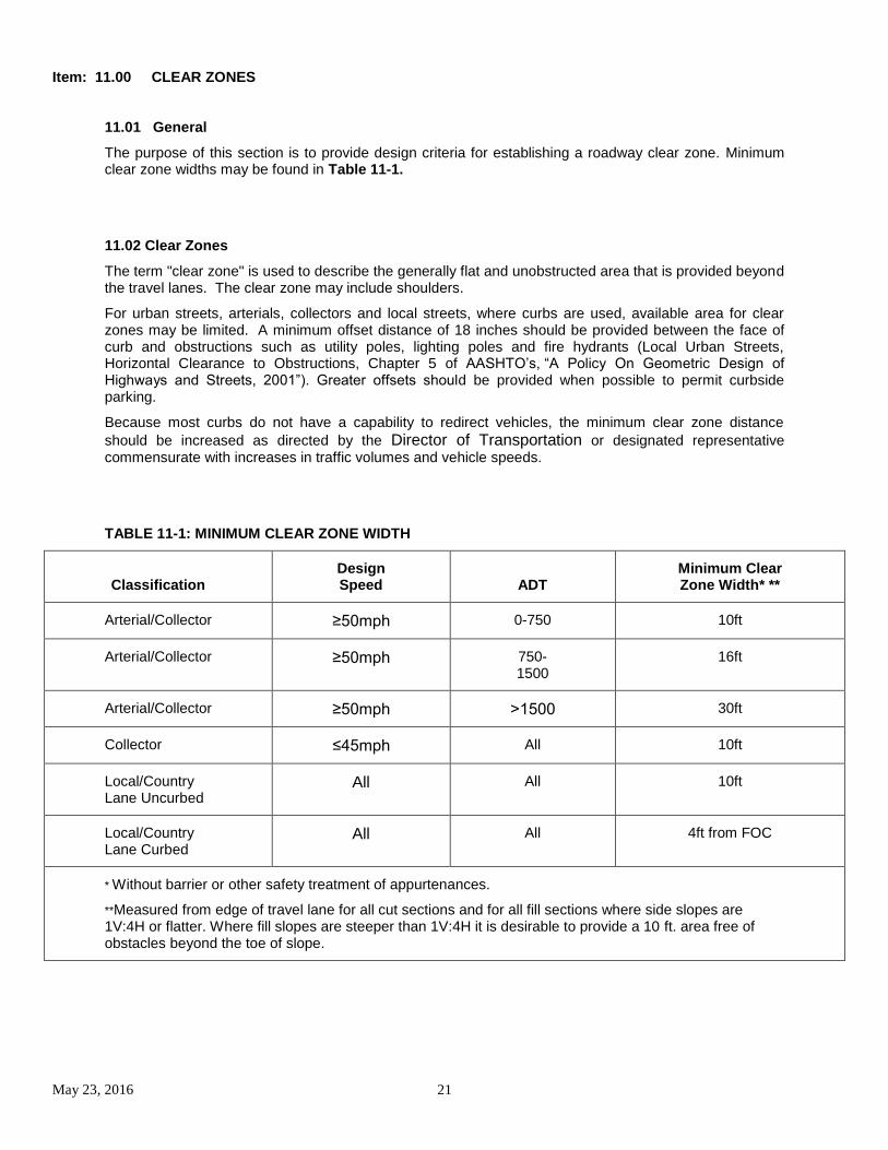
The purpose of this section is to provide design criteria for establishing a roadway clear zone. Minimum clear zone widths may be found in Table 11-1.
11.02 Clear Zones
The term "clear zone" is used to describe the generally flat and unobstructed area that is provided beyond the travel lanes. The clear zone may include shoulders.
For urban streets, arterials, collectors and local streets, where curbs are used, available area for clear zones may be limited. A minimum offset distance of 18 inches should be provided between the face of curb and obstructions such as utility poles, lighting poles and fire hydrants (Local Urban Streets, Horizontal Clearance to Obstructions, Chapter 5 of AASHTO’s, “A Policy On Geometric Design of Highways and Streets, 2001”). Greater offsets should be provided when possible to permit curbside parking.
Because most curbs do not have a capability to redirect vehicles, the minimum clear zone distance
should be increased as directed by the Director of Transportation or designated representative commensurate with increases in traffic volumes and vehicle speeds.
TABLE 11-1: MINIMUM CLEAR ZONE WIDTH
Classification Design Speed ADT
Minimum Clear Zone Width* **
Arterial/Collector ≥50mph 0-750 10ft
Arterial/Collector ≥50mph 750-1500
16ft
Arterial/Collector ≥50mph ˃1500 30ft
Collector ≤45mph All 10ft
Local/Country Lane Uncurbed
All All 10ft
Local/Country Lane Curbed
All All 4ft from FOC
* Without barrier or other safety treatment of appurtenances.
**Measured from edge of travel lane for all cut sections and for all fill sections where side slopes are 1V:4H or flatter. Where fill slopes are steeper than 1V:4H it is desirable to provide a 10 ft. area free of obstacles beyond the toe of slope.
May 23, 2016 22
11.03 Landscaping in the Right of Way
The following requirements will apply to all landscaping within the right-of-way along roadsides, median and intersection.
A. Intersections
No landscaping of any type shall obstruct vision. These requirements will apply to any material from a height of two (2) feet to a clearance height of eight (8) feet above the top of curb, including, but not limited to full grown trees, full -grown shrubs, fences, structures, any signs except traffic control signs, etc.
B. Traffic Control Devices
No landscaping of any type shall obstruct vision. These requirements will apply to any material from a height of seven (7) feet to a clearance height of fourteen (14) feet above the top of curb, including, but not limited to full grown trees, full-grown shrubs, fences, structures, any signs except traffic control signs, etc. within twenty-five (25) feet of any existing or proposed traffic signal, regulatory or warning signs, or other traffic control devices.
C. School Crossings
No landscaping of any type shall obstruct vision. These requirements will apply to any material with a height of two (2) feet or greater within one hundred fifty (150) feet of a school crossing to assure pedestrian safety by not restricting the
sight visibility of motorists.
D. Railroad Crossings
No landscaping of any type shall obstruct vision. These requirements will apply to any material with a height of two (2) feet or greater within two hundred fifty (250) feet of a railroad crossing to assure adequate sight visibility.
E. General Note
Any landscaping that is not in compliance with the requirements stated in these criteria or has been planted without an approved License Agreement from the County shall be removed by the sponsoring organization or individual at their cost. The required License Agreement may be obtained from the Hays County Road and Bridge Department.
Item: 12.00 MISCELLANEOUS
12.01 SIGNAGE
Street name signs, traffic control signs, speed limit signs, etc., shall all conform to the requirements of the most current TxDOT Standard Specifications and the "Uniform Manual of Traffic Control Devices". Sign posts shall conform to the COA detail 824-2 or an approved alternative. Stop bars shall be installed at all stop sign location. They shall be retro-reflective white thermoplastic material a minimum of 24” wide. They shall be placed adjacent to the stop sign and shall extend from the edge of pavement to the midpoint of the roadway. For all developments proposing new street construction, the developer's engineer shall provide - as part of the construction plans - a narrative statement in recordable format, to be recorded with the final plat, listing the type and location of all proposed signs for directing and controlling traffic.
12.02 COMPLETION CERTIFICATE Upon completion, but prior to acceptance of the work by Hays County Transportation Department, the accredited materials engineering laboratory shall submit to Hays County Transportation Department a written statement of substantial compliance which has been sealed by a professional engineer licensed in the state of Texas. The written statement of substantial compliance must acknowledge that all construction materials and operations used in the project were tested and inspected by accredited laboratory and that they comply with all the specifications applicable to the project. At the time a final inspection and release of performance security is requested; the design engineer shall provide a complete set of "as-built" Record drawings in PDF format (300 dpi) on a virus free disk and shall certify that all road and drainage construction has been completed in substantial accordance with previously approved plans and specifications, except as noted. No performance security will be released without these exhibits.