Embed Size (px)
Citation preview

SPECTRUM ONE
CCD Detection System
With CCD2000 and CCD3000 Controllers Including CCDLOAD.EXE and
CCD3000.EXE Drivers plus Windows DLL
Part Number 80119 Rev H Includes former 80120 Revised August 11, 2004

2
Copyright © August, 04 Instruments S.A., Inc., JOBIN YVON-SPEX Division. All rights Reserved. Portions of the software described in this document Copyright © Microsoft Corporation and Galactic Industries Corporation. All rights Reserved. No part of this document may be reproduced, stored in a retrieval system, or transmitted in any form by any means, including electronic or mechanical, photocopying and recording without prior written permission of Instruments S.A., Inc., JOBIN YVON-SPEX Division. Requests for permission should be submitted in writing. Information in this document is subject to change without notice and does not represent a commitment on the part of the vendor.

3
ABOUT THE MANUALS You may have more than one manual, depending on your system configuration. To find the manual that has the information you need, these guidelines may help.
• Each manual generally covers a product and the features and accessories peculiar to and/or contained within that product.
• Accessories that can be applied to other products are normally covered by separate documentation.
• Software that is exclusively used with one instrument or system is covered in the manual for that product.
• Software that can be used with a number of other products is covered in its own manual. • If you are reading about a product that interacts with other products, you will be referred
to other documentation as necessary.

4

5
TABLE OF CONTENTS: ABOUT THE MANUALS..................................................................................................................................... 3
OVERVIEW .......................................................................................................................................................... 6
SYSTEM COMPONENTS.................................................................................................................................... 7
OPERATING PRINCIPLES............................................................................................................................... 13
SPECIFICATIONS.............................................................................................................................................. 14
HARDWARE INSTALLATION......................................................................................................................... 16
TURNING THE SYSTEM ON ........................................................................................................................... 29
LN2 FILLING ...................................................................................................................................................... 32
FOCUSING AND ALIGNMENT........................................................................................................................ 34
SYSTEM OPTIMIZATION................................................................................................................................ 36
SERVICE POLICY ............................................................................................................................................. 41
APPENDIX A: GLOSSARY ............................................................................................................................... 43
APPENDIX B: AC POWER SELECTION AND FUSING................................................................................ 50
APPENDIX C: PC COMMUNICATIONS CARD ADDRESS, IRQ, AND DMA JUMPERS .......................... 51
APPENDIX D: INTERFACE DRAWINGS........................................................................................................ 53
APPENDIX E: CCDLOAD.EXE SOFTWARE DRIVER.................................................................................. 57
APPENDIX F: CCD3000.EXE SOFTWARE DRIVER ..................................................................................... 83
APPENDIX G: PROGRAMMING WITH THE WINDOWS DLL..................................................................125
INDEX.................................................................................................................................................................136

SpectrumONE CCD Detection System
6
OVERVIEW: The Spectrum One CCD detector systems are a family of products shared by the SPEX and Jobin-Yvon spectrometer product lines of Instruments SA. The Spectrum One series detectors are cooled Charge Coupled Devices (CCD’s) which provide two-dimensional photodetection for spectrometric applications. These detectors can be interfaced to the exit port of most SPEX and J-Y spectrographs, including those in fluorometers and Raman instruments. The glossary section of this manual starts on page 43. It contains definitions of terms and information about essential topics relating to CCD detection of spectra. Reading the glossary is recommended. The Spectrum One CCD system is well suited to applications such as:
• Low or very low signal levels such as Raman, fluorescence, and absorption spectroscopy. • Recording the spectra from multiple sources or locations that are imaged along the height
of the spectrograph entrance slit. • Near IR measurements to 1100 nm.

SpectrumONE CCD detection System
7
SYSTEM COMPONENTS: The Spectrum One CCD detection system consists of a detector head, a detector interface unit, and software. Additionally if the CCD2000 controller is used, a communications card which plugs into an IBM compatible PC with an available AT-style slot is required to run the system. If using the CCD3000 controller, a National Instruments IEEE-488 GPIB card is required to run the system.
Caution: Electrostatic discharge may damage components of the Spectrum One system if proper precautions are not taken. Refer to page 16 for instructions.
CCD Detector Heads: The Spectrum One CCD array head is available with three cooling options. When the lowest noise and dark level is required, liquid nitrogen (LN2) provides cryogenic cooling to reduce temperature and therefore, dark current, to the lowest level possible. Three types of thermoelectrically cooled heads are offered: a water cooled and two air cooled. The water cooled head requires circulating or flowing water rather than LN2. It provides operating temperature lower than the air cooled, though not nearly as low as the LN2 cooled heads. The air cooled heads operate at higher temperature, but require no water or LN2. For all heads, a resistive heater mounted in the detector allows software controlled temperature stabilization.
LN2 Cooled CCD Heads: LN2 cooled Spectrum One heads are mounted in one of three types of liquid nitrogen dewar assemblies. The 1 liter capacity dewar shown in Figure 1 is designed to maintain the CCD sensor cooled for at least 24 hours before refilling with liquid nitrogen.
1 LITRE DEWARMAN 0078
Figure 1: Spectrum One LN2 cooled head 1 liter dewar MAN0078
SpectrumONE CCD Detection System
8
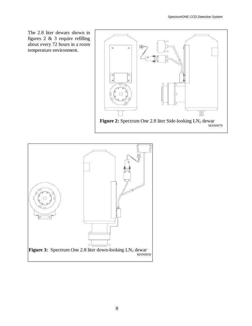
The 2.8 liter dewars shown in figures 2 & 3 require refilling about every 72 hours in a room temperature environment.
Figure 3: Spectrum One 2.8 liter down-looking LN2 dewar MAN0050
Figure 2: Spectrum One 2.8 liter Side-looking LN2 dewar
MAN0079

SpectrumONE CCD detection System
9
Thermoelectrically Cooled CCD Heads: Either liquid or air heat exchangers are provided for thermoelectrically cooled CCD detector heads. All types employ stage Peltier effect cooling devices inside evacuated or purged chambers. Several chip options are available in each type. These TE cooled heads can run continuously at their set operating temperature without refilling. For liquid cooled heads, a filter to remove particulates and other residue from the coolant is required to assure consistent heat exchanger performance. If a recirculating bath is used, it must have the capacity to dissipate more than 100 watts. The air cooled heads require only freely circulating ambient room temperature air to maintain cooling. A nominal air temperature of 22°C (72°F) is recommended. If the ambient air temperature at the head reaches 40°C (104°F), the chip temperature will certainly be affected. The total dissipation from the head will be about 100 watts. If the head must be mounted inside an enclosure, provide for forced ventilation to assure that the temperature in the enclosure is maintained at or below 35°C (95°F) for best results. If these conditions are not met, the operating temperature will be affected, and performance will be degraded.
With unrestricted airflow, the heat sink runs nominally 13°C above ambient. If, by airflow restriction or excessive ambient temperature, the heat sink ever exceeds 60°C, a sensor will signal the Peltier cooler power supply to shut down. In this way, damage to the head is prevented.
Figure 5: Spectrum One ATE air cooled head MAN0089
Figure 4: Spectrum One TE water cooled head
MAN0087
Figure 6: Spectrum One MTE air cooled head
MAN 0110

SpectrumONE CCD Detection System
10
Detector Head Evacuation: All Spectrum One detector heads except the MTE Mini head have a high vacuum chamber that holds the CCD chip. In the MTE head, the chamber is dried and filled with dry nitrogen at the factory. This chamber, along with other insulating measures, isolates the chip from the ambient temperature. The heads are evacuated or purged at the factory. They are designed to maintain insulating properties for a minimum of one year between pumping or purging cycles. A leak will result in a decrease in the insulating capability of the head. Thermoelectrically cooled heads will be unable to achieve their rated operating temperatures. LN2 heads will rapidly consume the liquid nitrogen, and frost may form on the exterior of the dewar. In either case, condensation may form on the array during cool down cycles, degrading optical performance and fostering corrosion. You may notice spreading of light to nearby pixels. Spectral features may become blurred. If the head cannot maintain operating temperature, contact ISA to arrange for re-pumping the vacuum or re-purging instructions. See page 14 for operating temperature specifications. Any attempts to evacuate the Spectrum One head at user locations are not recommended. Some types of vacuum pumps can backstream oil, causing irreparable damage to the CCD electronics. In the event of loss of vacuum, please contact the ISA Service Department according to the directions given on page 41.
CCD 2000 Detector Controller: The CCD2000 Detector Controller Unit shown in controls the CCD head based on commands from the computer. This unit supplies power, clocking signals, and biases to the CCD sensor array. If the head is TE cooled, it provides power to the Peltier cooler. The Controller unit also amplifies and digitizes the signal as it is collected from the CCD.
CCD-2000
CHASSIS GND
COOLERPOWER SUPPLY
COMPUTER
INREF
OPTIONALSHUTTER
DETECTOR
FUSESHUTTER
MADE IN USA
FUSE3AG SLOW BLOW115VAC @ 2 AMPS230VAC @ 1 AMP
WARNING:NO OPERATOR
PARTS INSIDE;
QUALIFIED SERVICE
SERVICEABLE
REFER SERVICING TO
PERSONNEL.
Instruments S.A., Inc.
JOBIN YVON SPEX
DIGITALI/O
3AG FAST BLOW1 AMP
TE STATUS
POWER
1
0
Figure 7: CCD2000 Detector Controller MAN0107

SpectrumONE CCD detection System
11
CCD 3000 Detector Controller: The CCD3000 Detector Controller Unit shown in Figure 8 controls the CCD head based on commands from the computer. This unit supplies power, clocking signals, and biases to the CCD sensor array. The Controller unit also amplifies and digitizes the signal as it is collected from the CCD.
Triggering with CCD3000 Controller The CCD3000 has two external trigger ports: TRIGGER INPUT and TRIGGER OUTPUT. If using SpectraMax for Windows software with triggers enabled, when the controller is ready to acquire, the TRIGGER OUTPUT line is moved high and the controller waits for a positive pulse from the TRIGGER INPUT to start the acquisition. When an input pulse is received, the output line is moved low until the controller is ready for the next acquisition. The triggers can also be controlled via a user programmed interface (See appendix sections for more information).
PC Communications Card
CCD 2000: To facilitate the high speed data transfer needed to and from the CCD detector, a Reduced Instruction Set Computer (RISC) is employed on the communications card (see figures 9). The RISC card must be mounted in the IBM compatible PC to allow the computer to communicate with and operate the Detector Interface Unit.
CCD 3000: This controller is designed to transfer data via IEEE-488 communication. If using ISA software, the user must supply a National Instruments compatible card. The following cards are approved National Instruments PC interface boards:
CCD-3000
CHASSISGROUND
COOLERPOWER SUPPLY
IEEE-488
INPUT OUTPUT
+15 V BIASEXTERNAL DETECTOR
DETECTOR
MADE IN USA
FUSE3AG SLOW BLOW115VAC @ 2 AMPS230VAC @ 1 AMP
NO OPERATOR SERVICEABLE PARTS INSIDE.
REFER SERVICING TO QUALIFIED SERVICE PERSONNEL.
INPUT
ONLYTTL
TRIGGERTRIGGER
Figure 8: CCD 3000 Detector Controller
MADE IN U.S.A.
ASSEMBLY # 37993SER IAL #
C C D 2000 D IGITAL C ON TR OLLER
R EV.B
S-TAB S-TAB
1
A31 A1
1
1
1
1
Figure 9: PC Communications card

SpectrumONE CCD Detection System
12
• AT-GPIB/TNT and AT-GPIB/TNT(PNP) • GPIB-PCII/PCIIA 488.2 Interface board: The driver supplied by National should be
version 1.2 or newer, and their BASIC support disk should be version 2.0 or newer. • Older GPIB-PCIIA boards require National’s revision C13 or newer software. • AT-GPIB 488 boards require National’s revision E7 or newer software. • AT-GPIB 488.2 board: Must be version 2.1.1 software, and their BASIC support disk
version 2.2 or newer. • GPIB-PCIII board: this model must be replaced with one of the above.
There are other boards by National and other suppliers for IBM compatible computers. Many of these boards can function in SIMILAR fashion. As we cannot support or guarantee reliable communications with other boards and software, we strongly recommend that you use the National Instruments products described above.
Software: A variety of software options are available from Instruments SA to operate the Spectrum One CCD detector system. Please refer to the documentation provided with the software shipped with the system. Instruments SA is committed to continuous development and improvement of software. To the extent possible, new software options are developed with backward compatibility. In this way, normally an existing system can be upgraded as new software is developed. It is advisable to keep in contact with Instruments SA to be sure that updates and new software options that can enhance the system’s functionality are considered as they become available.

SpectrumONE CCD detection System
13
OPERATING PRINCIPLES: CCD detector arrays are essentially large area silicon photodiodes constructed such that the area is divided into a two dimensional matrix of pixels. When illuminated by opening the shutter, each pixel integrates a charge arising from the photoelectric effect. The charges of adjacent pixels are kept separated by a grid of electrodes that confine the charges by electrostatic force. At the end of the signal integration time the shutter is closed. Then the electrode grid voltages are manipulated by control signals from the Detector Interface Unit. This will sequentially shuttle the pixel charges row by row or column by column to the edge of the chip into a read out register. Based on the controlling software’s settings, the Detector Interface Unit can cause the readout to be formatted as either individual pixel datapoints or as areas of several pixels binned into superpixels. The signal from the CCD is processed, amplified and converted to digital datapoints by electronics in the Detector Interface Unit. The data is passed from the Detector Interface Unit to the memory of the computer. This allows the software running in the host PC to access it rapidly for further processing and display. The readout rate of a slow scan scientific grade CCD is about 20 kHz. The CCD’s used in television cameras, where S/N is less critical, scan at about 60 MHz.
Readout Register
Acitve Pixels
Figure 10: CCD Readout Registers

SpectrumONE CCD Detection System
14
SPECIFICATIONS: ADC Precision: 16-bit Dark Current: LN2 Cooled Head: < 1 to 3 e-/pixel/hour (chip dependent) H20 Cooled Head: < 50 electrons/pixel/hour Air Cooled Head: < 250 electrons/pixel/hour Mini Air Cooled Head: < 2.5 electrons/pixel/second Dynamic Range: 65535 counts max. Electrons/Count: Variable, from 1 to 16 e-/count Exposure Time: >10 milliseconds to hours Typical Operating Temperature: LN2 Cooled Head: -140o C typical, (1024 x 256 pixels, larger -70 to -140o C range chips slightly higher) H20 Cooled Head: -60oC (water 12o C) Air Cooled Head: -55oC (air 22o C) Mini Air Cooled Head: Not specified Quantum Efficiency: Standard chips: Up to 50% at 750 nm. Backthinned chips: Up to 85% at 550 nm. Spectral Response: Standard chips: 400 to 1050 nm. With UV coating: 200 to 1050 nm Readout Noise: LN2 Cooled Head: 4 to 10 electrons RMS per pixel or binned datapoint, depending on chip selected H20 Cooled Head: 10 to 18 electrons RMS per pixel or binned datapoint, depending on chip selected Air Cooled Head: 10 to 20 electrons RMS per pixel or binned datapoint Mini Air Cooled Head: 10 to 20 electrons RMS per pixel or binned datapoint Specifications are subject to change without notice.

SpectrumONE CCD detection System
15

SpectrumONE CCD Detection System
16
HARDWARE INSTALLATION:
Warning: The CCD head, the Detector Interface Unit, the RISC board and the computer are very sensitive to electrostatic discharge (ESD). ESD precautions should be followed. The installer should stand on a conductive mat and wear a grounded wrist strap during installation. The computer must be turned off, but its power cord should be connected to a grounded outlet to take advantage of the outlet ground. Always turn the power off to all components before connecting or disconnecting any cables. Before inserting a connector, touch the connector shell to the component case to discharge any accumulated static charge.
Communications Card (for the CCD 2000 only): Mount the Spectrum One communications card in the computer to allow connection of the Detector Interface Unit to the computer. To install the communications card: 1) Shut off the computer and remove the chassis cover. 2) Choose a slot (AT-style) as far from the video and disk cards as is practical (These cards
have been know to artificially increase the noise level.) Remove the rear panel slot cover, retaining the screw.
3) Insert the edge connector of the communications card shown into the chosen slot, making
sure of good contact. Fasten the back plate with the screw removed from the slot cover and replace the chassis cover of the computer.

SpectrumONE CCD detection System
17
Detector Head Mounting: The Spectrum One can be retrofitted to an existing Spex or J-Y spectrometer that can be equipped with a spectrograph exit port. Instructions for adding the appropriate spectrograph ports follow. If the spectrograph port is already installed, note the mask on the face of the detector before mounting. This mask is offset to one side to accommodate the tilt of the focal plane without vignetting.
For Raman Systems: User installation of the CCD on the S30900, U1000, and T64000 is not recommended without first consulting with ISA’s Raman Service Department (see service policy section on page 41). Thermoelectrically cooled Spectrum One heads can be mounted on any ISA Raman system. For the S3000, use the model 640.20.10.10 adapter which also can mount a side-looking LN2 dewar as well. The U1000 requires the model 505.85.911 adapter. Either down-looking dewars or TE heads can be mounted on the 505.85.911. The T64000 has a built-in port for the down-looking dewars or TE heads, a side looking dewar or additional TE head mounting can be added by mounting the optional T64.POR adapter.
For the 270M: Use the 270MCA adapter. Refer to the 270M manual for instructions.
For HR320, THR640, THR1000: The model 303.50.713 XYZ Spectrograph port (see figure 14) is the adapter used for the HR320, THR640, and THR1000. This will adapt the side-looking CCD dewar or TE cooled CCD head to the spectrometer. Remove the slit assembly or cover from the exit port by unscrewing the three mounting bolts. Bolt the Detector Mounting Adapter onto the port. The adapter consists of two sections, one of which fits into the other. Bolt the mounting fixture to the outer surface of the port plate (wall) using the three included screws. The HR320 uses M5x10 flathead screws while the THR640 and THR1000 use M4x12 flathead screws. Orient the mounting fixture such that the notch is to the left. Then mount the tilting/focusing adapter with the groove in the flange and the swivel washer set at the top. Snug the thumb-nuts. They will be tightened later when finished with the tilting and focusing adjustments. Bolt the Spectrum One head to the detector mounting flange. Snug the three bolts. These will be tightened later after the rotation adjustment is completed.
SpectrumONE CCD Detection System
18
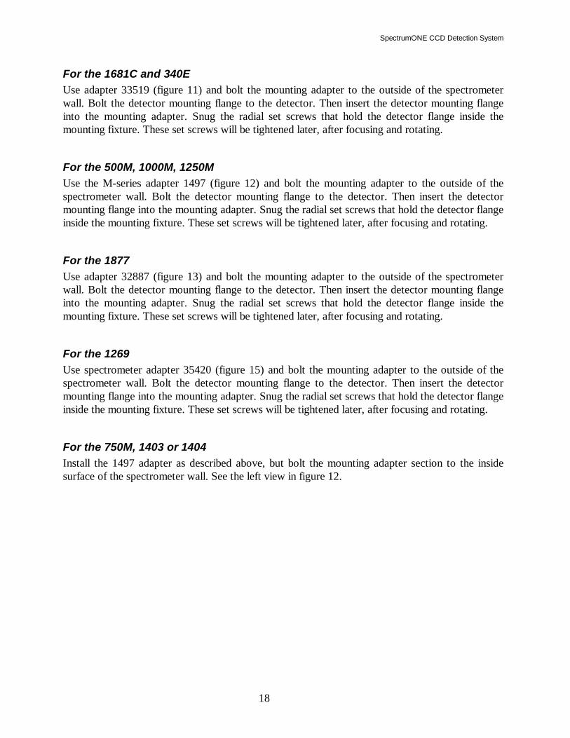
For the 1681C and 340E Use adapter 33519 (figure 11) and bolt the mounting adapter to the outside of the spectrometer wall. Bolt the detector mounting flange to the detector. Then insert the detector mounting flange into the mounting adapter. Snug the radial set screws that hold the detector flange inside the mounting fixture. These set screws will be tightened later, after focusing and rotating.
For the 500M, 1000M, 1250M Use the M-series adapter 1497 (figure 12) and bolt the mounting adapter to the outside of the spectrometer wall. Bolt the detector mounting flange to the detector. Then insert the detector mounting flange into the mounting adapter. Snug the radial set screws that hold the detector flange inside the mounting fixture. These set screws will be tightened later, after focusing and rotating.
For the 1877 Use adapter 32887 (figure 13) and bolt the mounting adapter to the outside of the spectrometer wall. Bolt the detector mounting flange to the detector. Then insert the detector mounting flange into the mounting adapter. Snug the radial set screws that hold the detector flange inside the mounting fixture. These set screws will be tightened later, after focusing and rotating.
For the 1269 Use spectrometer adapter 35420 (figure 15) and bolt the mounting adapter to the outside of the spectrometer wall. Bolt the detector mounting flange to the detector. Then insert the detector mounting flange into the mounting adapter. Snug the radial set screws that hold the detector flange inside the mounting fixture. These set screws will be tightened later, after focusing and rotating.
For the 750M, 1403 or 1404 Install the 1497 adapter as described above, but bolt the mounting adapter section to the inside surface of the spectrometer wall. See the left view in figure 12.

SpectrumONE CCD detection System
19
FOCALPLANE
SET SCREW10-32 X 1/4 LG.
HEX SOCKET CAPSCREW 4 ON 2.375BOLT CIRCLE.
8-32 3 ON 3.600BOLT CIRCLE.
INS
TRU
ME
NT
W
ALL
2.75 4.50
MIN/MAX1.0"/1.5"
1.875 Figure 11: 33519 Spectrograph Adapter for 1681C MAN 0094
SECTION A-A
FOC
AL
PLA
NE
INSTRUMENT WALL FOR500M,1000M AND 1250M.
FOC
AL
PLA
NE
INSTRUMENT WALL FOR750M, 1403 AND 1404.
MAX.3/4"
1/4-20 - 4 ON
ON 3.6 BOLT
3 ON 3.875BOLT CIRCLE
10-32 X 1/4"SET SCREW
1 1/2"
MIN. 0"
CIRCLE
8-32 - 3
Figure 12: 1497 Array Adapter for 500M-1250M, 1403, 1404 MAN 0103

SpectrumONE CCD Detection System
20
INSTRUMENT
FOCALPLANE
R
INSTRUMENTWALL
FOCUS (Z)
TILT (X,Y)
M5 x 0.8 TAPPED HOLES (6)EQUALLY SPACED ON3.60 INCH B.C.
F RNOMINAL RANGE
HR 320
HR 640
THR 640
THR 1000
*
31.5
NOTE: WHEN USING THR640 ACCESSORY #21.330.020`FOCUSING SLIDE`, THE RANGE (R) BECOMES 0 to 28.
-2 to 11
67.6 3 to 16
33 0 to 13
33 0 to 13
4.5 DRILL THRU3 HOLES ON 123 B.C.
BAFFLE -- 8 x 30 mmCLEAR APERTURE
102.0Ø
66.05±.05 Ø
32.0 Ø
F
Figure 14: 303.50.713 Array Adapter for HR320, HR640, THR1000 MAN102
FOCALPLANE
1/4-20 HEX SOCKETCAP SCREW 4 PLACESON 3.875 BOLT CIRCLE.
Ø1/4 DOWELS2 PLACES
MAX 2.750
10-32 HEX SOCKETCAP SCREW 4 PLACESIN RECTANGULAR PATTERN
INST
RU
MEN
T
WAL
L
8-32NC 0N3.600 BOLTCIRCLE
3 PLACESEQUALLYSPACED ON3.875 BOLTCIRCLE.
3.050
MIN 2.250
2.373.550
4°
Figure 13: 32887 Spectrograph Adapter for 1877 Triplemate MAN 0095

SpectrumONE CCD detection System
21
1.125 /1.687
7/32 DIAMETER3 EQUALLY SPACEDON 3.875 BOLT CIRCLE
8-32 NC3 EQ. SPACEDON 3.600 BOLTCIRCLE
HEX SOCKET HEADCAP SCREW 1/4-20X 3/4 LONG. 4 PLACES
FOCALPLANEPOSITION
1.00
1.875
MIN / MAX
Figure 15: 35420 Adapter for 1269 Spectrometer MAN 0100

SpectrumONE CCD Detection System
22
Detector Positioning: Note the mask on the face of the detector before mounting. This mask is offset to one side to accommodate the tilt if the focal plane for imaging spectrographs. For the HR460 and 270M, the aperture should be shifted towards the side that will be closest to the grating when mounted. If the mask is in the wrong position, carefully remove it (avoid disturbing the window) and reverse it. The final focusing and alignment of the detector can only be accomplished with the software running. In this way, the signal detected can be monitored during the final positioning of the array. The shape of the signal can then be used as an alignment indicator. Install the cabling and shutter as explained in the following sections. The next section deals with software installation (page 28). Then see the Focusing and Alignment section (page 34) which explains the principles involved in positioning the detector array in the focal plane of the spectrograph. A general Alignment and focusing procedure is outlined there as well. More specific instructions are given in the Software manual. See the Software Installation section of this manual as well (page 28). The spectrometer and its associated grating(s) are aligned together at the factory. Performance data in the form of calibration reports and plots are shipped with the instrument. Normally no adjustments to the grating mounts or other internal optomechanical components are needed to obtain the specified performance. If there is reason to suspect that the instrument has become misaligned, review the spectrometer manual. If help from Instruments SA is required, refer to page 42 for information about contacting ISA.

SpectrumONE CCD detection System
23
Mounting the Shutter: The CCD shutter model number varies depending on the spectrograph used.
Shutter models 22.900.131, 22.900.129, & 21.384.710 for the S3000, U1000, & T64000 respectively. Contact the ISA Service Department for assistance in installing the shutter onto the S3000, U1000 or T64000 Raman systems (see the Service Policy section page 41).
Shutter models 225MCD or 227MCD for the 270M Spectrometer. The 225MCD shutter mounts outside on the axial (front) or lateral (side) entrance slit. Alternatively, the model 227MCD mounts inside the front axial entrance port. See the 270M manual for detailed installation instructions. Connect the BNC-to-9-pin cable to the 9-pin connector on the cable coming from the CCD head. For the externally mounted 225MCD shutter, connect the BNC end to the BNC connector on the outside of the shutter mechanism. For internally mounted 227MCD shutters, connect the BNC end to the BNC connection inserted through the purge port.
Shutter model 22.900.109, for the CP200, HR320, THR640, THR1000, & THR1500 Spectrometers Screw the shutter onto the 28 mm threaded adapter on the entrance slit of the spectrometer. Connect the 32617 BNC-to-9-pin connector cable to the BNC connector on the shutter and to the 9-pin connector on the branch of the 35872 cable to the CCD head.
FEMALETHREAD
28 X 1mmMALETHREAD
BNC CONNECTORFOR SHUTTER DRIVE
Figure 16: 22.900.109 Shutter for CP200 and HR-Series Spectrometers MAN 0105

SpectrumONE CCD Detection System
24
Shutter model 1425MCD(-series), for the 1681C, 340E/S, 500M, 750M, 1000M, 1250M, 1269, 1403, and 1404 Spectrometers. Mount the model 1425MCD (See figure 17) shutter internally on the axial (front) slit. For the 1000M and 1250M, it can also be mounted internally on the lateral (side) entrance slit. For the axial (side) entrance of the 500M or 750M, use the 1424MCD-B. For dual entrance spectrometers, if shutters are required at both entrances, choose the correct shutter for the lateral slit, and add a 1425MCD-C for the axial slit. For all listed spectrometers except the 1681C and 340E, use two 1/4 -20 capscrews to attach the shutter support to the inside of the instrument wall. For the 1681C and 340E, use two 10-32 screws, and mount the shutter vertically, to avoid interference with the light baffle. Remove the plug from the purge port of the spectrometer and using the wired BNC connector, screw the threaded end of the BNC connector into the purge port such that the wire hangs inside. Route the wires avoiding the optical path and moving parts inside the spectrometer. Connect the wiring from the shutter to the BNC connector. Connect the 36217 BNC-to-9-pin connector cable to the BNC connector just installed, and to the 9-pin connector on the 35872 cable coming from the CCD head.
Shutter model 1825MCD for the 1877 Triplemate Spectrometer. The 1825MCD mounts internally on the entrance slit of the spectrograph stage. Use the two 1/4 -20 capscrews included. Remove the plug from the purge port of the spectrometer and using the wired BNC connector, screw the threaded end of the BNC connector into the purge port such that the wire hangs inside. Route the wires avoiding the optical path and moving parts inside the spectrometer. Connect the wiring from the shutter to the BNC connector. Connect the 36217 BNC-to-9-pin connector cable to the BNC connector just installed, and to the 9-pin connector on the 35872 cable coming from the CCD head.
Shutter model 1625MCD for the 340E/S, 1681C Spectrometers The model 1625MCD shutter mounts externally behind either the axial (front) or the lateral (side) entrance slit.

SpectrumONE CCD detection System
25
Connect the 36217 BNC-to-9-pin connector cable to the BNC connector on the shutter and to the 9-pin connector on the 35872 cable coming from the CCD head.
INSTRUMENT WALL
CLEARANCE HOLESFOR 10-32 X 1/4"FOR 1681, 340 SERIES
1/4-20 X 3/8" HEX SOCKETCAP SCREWS FOR 500M,1250M1403,1404 AND 1877 (2)
Figure 17: 1425MCD Shutter for 1681C, 340, 500-1250M, 1400 Spectrometers
MAN 0106

SpectrumONE CCD Detection System
26
Electrical Connections for CCD-2000:
Warning: Do not disconnect system cables while any components are powered on. The resulting electrostatic discharge may damage the electronics.
1) Switch the power off at the rear panel power
input module of the Detector Interface Unit. Turn off the computer as well. Using the 99603 twisted pair ribbon cable, connect the “computer” connector of the Interface Unit (see Figure 7) to the D-shell connector on the PC communications card installed in the computer.
2) With the CCD2000 power off, connect the
female 37-pin connector on the Interface Unit to the 37-pin connector on the 35872 cable.
3) For thermoelectrically cooled heads a 9 pin
male to female 37661 cable is provided to connect the cooler power supply in the CCD2000 to the head.
For the high performance air and water cooled heads, the connector on the CCD-2000 is female and the connector on the head is male. For the Mini head, this is reversed. The power requirements of the Mini head’s cooler differ from the others. This connector arrangement prevents damage due to mismatching.
4) Remove the grounding connector from the
25-pin connector on the Spectrum One detector head. Connect the 35872's 25-pin connector of the adapter cable to the CCD, first touching the cable connector shield to the metal case of the head to drain any static charge.
CCD-2000
CHASSIS GND
COOLERPOWER SUPPLY
COMPUTER
INREF
OPTIONALSHUTTER
DETECTOR
FUSESHUTTER
MADE IN USA
FUSE3AG SLOW BLOW115VAC @ 2 AMPS230VAC @ 1 AMP
WARNING:NO OPERATOR
PARTS INSIDE;
QUALIFIED SERVICE
SERVICEABLE
REFER SERVICING TO
PERSONNEL.
DIGITALI/O
3AG FAST BLOW1 AMP
1
0
Figure 7: Detector Interface connections
MAN 0107

SpectrumONE CCD detection System
27
NOTE: To prevent Electrostatic Discharge (ESD) damage, insert the grounding plug into the connector on the detector head whenever the CCD head is disconnected.
5) The 9-pin shutter connector that branches off the same 35872 cable attaches to the shutter
after the shutter Installation is completed. See page 28 for further information.
Electrical Connections for CCD-3000:
Warning: Do not disconnect system cables while any components are powered on. The resulting electrostatic discharge may damage the electronics.
1) Switch the power off at the rear panel power input module of the Detector Interface Unit.
Turn off the computer as well. 2) With the CCD3000 power off, connect the IEEE-488 connector in the host computer to the
IEEE-488 connector on the controller. 3) Remove the grounding connector from the 25-pin connector on the Spectrum One detector
head. Connect the 35872's 25-pin connector of the adapter cable to the CCD, first touching the cable connector shield to the metal case of the head to drain any static charge.
NOTE: To prevent Electrostatic Discharge (ESD) damage, insert the grounding plug into the connector on the detector head whenever the CCD head is disconnected.
4) The 9-pin shutter connector that branches off the same 35872 cable attaches to the shutter
after the shutter Installation is completed. See page 28 for further information.

SpectrumONE CCD Detection System
28
SOFTWARE INSTALLATION: The controlling software must be configured for a CCD and installed properly in order for the Spectrum One to operate. When the system is ordered with the computer, the software will be installed and tested at the factory. In those cases where the user must install the software, The configuration files for the system are provided on the installation diskettes. Simply follow the installation directions in the manual provided with the software. The software includes the Spectrum One Initialization routine used to monitor the chip temperature as the head cools to its specification.
For SpectraMax for Windows Software:
• Install SpectraMax for Windows software on the computer. Follow the procedure in the SpectraMax for Windows manual.
For SpectraMax (DOS) Software:
• Install SpectraMax software on the computer. Follow the procedure in the "Getting Started" section of the SpectraMax software manual.
•

SpectrumONE CCD detection System
29
TURNING THE SYSTEM ON There is a particular sequence that must be followed for activating the Spectrum One system. It is important that LN2 is not filled before the power up sequence is completed. This insures that the CCD will be initialized properly. The system will not function properly otherwise.
Caution: The Detector Interface Unit must be turned on and initialized before liquid nitrogen is added to the dewar.
In Case of Power Interruption: For thermoelectrically cooled heads, restart as normal. For LN2 cooled heads, if power is interrupted while the detector is cooled the system can be restored to normal operation by performing the following steps:
• Repower the system as usual • Reinitialize the CCD • Note that the sensor may be at a lower than normal operating temperature due to loss
of thermostat control while unpowered. Allow enough time for the sensor to return to normal operating temperature.
• Run a series of full area readouts with short integration time. This will flush most
trapped charges from the CCD sensor. For most cases, normal operation can be resumed at this point.
• For those cases where very long integration times are used, an increase in dark charge
may be noticeable. If the effect is small and subtractible, proceed as normal, but take background spectra at more frequent intervals. If this effect happens to be large compared to the desired signal, the dewar should be allowed to warm to room temperature and then reinitialized to clear all trapped charges.
For SpectraMax for Windows Systems: Turn on the spectrometer and its associated SPEX/JY 232/488 interface, DataScan or SpectrAcq controller if so equipped, then the CCD2000 or CCD3000 Detector Interface Unit, and computer. From the Windows program group "SpectraMax for Windows," double-click the HWINIT icon to start the DOS program that initializes the CCD hardware (HWINIT not present for CCD3000

SpectrumONE CCD Detection System
30
controller). The CCD Initialization routine will monitor the temperature while the CCD is cooling to operating temperature. For LN2 heads, add liquid nitrogen as per the instructions on page 32. Then, continue with the CCD Initialization as per the instructions on page 31.
For SpectraMax (DOS) Systems: Turn on the spectrometer and its associated SPEX/JY 232/488 interface, DataScan or SpectrAcq controller if so equipped, then the CCD2000 or CCD3000 Detector Interface Unit, and computer and type “SM <Enter>”at the DOS prompt for the drive where SpectraMax is loaded. The SM.BAT batch file will run the HWINIT program to initialize the CCD and load SpectraMax. The CCD Initialization routine will monitor the temperature while the CCD is cooling to operating temperature. For LN2 heads, add liquid nitrogen as per the instructions on page 32. Then, continue with the CCD Initialization as per the instructions on page 31.
For Systems with SpectraLink Controllers: Turn on the SpectraLink, the Spectrum One Detector Interface Unit, and computer and type SpectraMax <enter> at the DOS prompt for the drive where SpectraMax is loaded. The SM.BAT batch file will run the HWINIT program to initialize the CCD and load SpectraMax. The CCD Initialization routine will monitor the temperature while the liquid nitrogen is added to the dewar and the CCD is cooling to operating temperature. Add liquid nitrogen as per the instructions on page 32. Then, continue with the CCD Initialization as per the instructions in the next section.

SpectrumONE CCD detection System
31
INITIALIZATION (FOR CCD2000 CONTROLLER): The HWINIT (HardWare INITialization) program sets up a number of operating parameters in the CCD controller. Then it monitors the two temperature sensors in the CCD head. One sensor indicates the temperature of the liquid nitrogen or the warm side of the Thermoelectric cooler (SINKTMP). The other monitors the temperature of the metal block to which the CCD is mounted to give the temperature of the CCD itself (CCDTEMP1). On the computer screen, two lines of data appear, one for each of the sensors. The data in the first two columns next to these labels fluctuates: the first value is the raw signal count from the sensor and the second value is the sensor temperature in Kelvin. The numbers in the last two columns are the minimum and maximum Kelvin temperatures for the temperature indicator scale at the right. For LN2 heads, it will take approximately 30 to 40 minutes from the beginning of cooling the detector until it reaches its target temperature. Thermoelectrically cooled heads will reach operating temperature in 15-20 minutes. This time will also vary depending on the size of the chip. Note that for best results in the most demanding measurements, it is best to allow 60 to 90 minutes for the CCD chip to stabilize completely. The initialization routine will continuously display the temperature. When the second value in the row labeled CCDTEMP1 has stabilized at or near the target temperature, type “E” to exit the temperature monitoring loop and continue with the rest of the HWINIT program. Exiting before the temperature is stabilized may cause errors in data collection. The CCD Initialization program sets the operating parameters of the CCD based on the assumption that it has reached operating temperature, and that the head will remain stable at that temperature maintained by the detector interface unit. Changes in temperature after the parameters are set will affect the data. If there is reason to believe that changes in the operating conditions of the lab may have affected the temperature of the CCD, re-initialize the detector.
Periodic Initialization: It is suggested that the CCD Initialization program be run once a day, prior to taking any critical measurements. In this way, adjustments can be made to the CCD settings for any variations in environmental conditions or dewar temperature. Refer to previous section, Initializing the CCD.
Type E when a stable temperature is reached! SINKTMP 33354 287 80 300 . | . CCDTEMP1 33202 210 125 300 . | . Average Sinktemp = 286.9 Average Ccdtemp = 209.5
HWINIT Temperature Display

SpectrumONE CCD Detection System
32
LIQUID NITROGEN PRECAUTIONS
Warning: Liquid Nitrogen requires special handling. Read this section carefully before filling the dewar.
Ventilation: In confined spaces lacking adequate ventilation, nitrogen gas can displace air to the extent that it can cause asphyxiation. Always use and store liquid nitrogen in well-ventilated spaces.
Extreme Cold: The boiling point of liquid nitrogen at atmospheric pressure is 77.3 K (about -156oC). This extreme cold can cause tissue damage similar to a severe burn. Therefore, exposure of the skin or eyes to the liquid, cold gas, or liquid-cooled surfaces must be avoided. The liquid should be handled so that it will not splash or spill. Gloves impervious to liquid nitrogen and goggles should be worn when handling the liquid. Feet can be protected by wearing rubber boots, with trousers (without cuffs) on the outside.
Storage and Transfer: Liquid nitrogen should always be stored in vacuum-insulated containers, which should be loosely covered but not sealed. Covering prevents moisture condensing out of the air to form ice which may cause blockage. Sealing results in pressure buildup. DO NOT ATTEMPT TO SEAL THE MOUTH OF THE DEWAR! The gas-to-liquid volume ratio is about 680:1. All containment vessels must therefore be fitted with exhaust vents to allow evaporating gas to escape safely. If these vents are sealed, pressure will build up rapidly and may result in the fracture of the containment vessel.
LN2 Filling Instructions:
Caution: The Spectrum One Detector Interface Unit must be turned on and the HWINIT program must be running before the dewar is filled.
If the system is off, turn on the system following the “Turning the System On” procedure as outlined on page 29. In the event of power failure, turn the unit off, let the dewar warm to room temperature, then start over with the “Turning the System On” procedure.

SpectrumONE CCD detection System
33
Take care not to overfill. If the liquid nitrogen is spilled on apparatus around or below the detector, the resulting thermal shock may have a detrimental effect.
Using a pressurized storage vessel: Remove the cap and insulating plug at the top of the detector dewar, insert the fill tube, and let the nitrogen flow into the dewar.
Using a funnel and transfer dewar: Insure that the funnel has ribs to provide gaps to vent the boiled off vapor as the liquid nitrogen is added. Set the funnel into the mouth of the dewar. Pour the liquid nitrogen into the funnel slowly. The dewar is full when the liquid nitrogen reaches the bottom of the narrow neck of the dewar. A probe such as a clean wooden dowel may be inserted and removed to reveal a frost line indicating the nitrogen level.
Periodic Filling: The larger, 2.8 liter dewar permits continuous cooled operation of the CCD by virtue of its 72-hour hold time. The smaller, 1 liter dewar, with a hold time of 24 hours, is designed for more intermittent operations. Note: The electronics must be activated in the proper sequence (computer, then Detector Interface Unit) before liquid nitrogen is added to the dewar. Replace the cap when the dewar is full. The cap is insulated to help extend the interval between fills. It also minimizes moisture condensation into the dewar. The loose fit of the cap prevents pressure buildup in the dewar by allowing evaporating nitrogen to escape. When filling the dewar, an initial period of nitrogen boiling and overflow occurs until the internal components of the dewar have cooled to liquid nitrogen temperatures. After this initial boil-off period, refill the dewar as needed to extend the cold temperature hold time.

SpectrumONE CCD Detection System
34
FOCUSING AND ALIGNMENT: Once the Spectrum One head is mounted and the system connected, the position of the head must be adjusted so that the CCD sensor lies at the instrument focal plane, and that the spectral slit images are aligned with the pixel columns.
Note: The head must first be cooled to operating temperature before the CCD can be focused and aligned.
With SpectraMax for Windows software: 1) Attach a spectral
line source, such as a mercury lamp, to the instrument entrance slit. Reduce the slit width to make the image of the slit as narrow as possible on the detector. This will allow determination of the best focus.
2) Start the RTD
portion of the software.
3) Set the “Integration Time" to 0.1 second, and select continuous spectrum acquisition and
screen update by pressing the Up Arrow on the Spectrometer Step Control.
4) Begin live acquisition. 5) Observe the spectra. A focused, aligned CCD will provide a distinct symmetrical peak of
large amplitude. The peak should be less than or equal to 5 pixels wide across the Full Width of Half the Maximum height (FWHM). Asymmetry of the peak is a sign that the slit image is not aligned to the pixel columns; diminished shape and magnitude are symptomatic of defocusing. (Figure 17)
6) Loosen the set screws on the adapter barrel. Adjust the CCD sensor plane position by
moving the head in and out with respect to the exit port. (The CCD plane is approximately
Aligned & Focused Misaligned; Asymmetric Defocused; Broad
Figure 17: Examples of peaks during Alignment and Focusing

SpectrumONE CCD detection System
35
9.5 mm, or 3/8", behind the mating surface of the detector head’s mounting flange.) The CCD orientation is adjusted by rotating the detector head to the right or left in the exit port.
7) Verify that the alignment is good by acquiring an image. When the output is imaged,
alignment results in an upright, sharp image of a spectral diffraction pattern on the computer. 8) Tighten the set screws in the outer adapter barrel once the CCD has been aligned and
focused. To optimize the linearization of the system, refer to the SpectraMax for Windows software manual.
With SpectraMax for DOS software: Refer to the CCD Acquisition section of the SpectraMax for DOS Manual for complete information and instructions.

SpectrumONE CCD Detection System
36
SYSTEM OPTIMIZATION: After completing the installation, some applications demand further, special attention to assure that the CCD detection system is yielding the best possible signal to noise ratio. The following topical discussions may be helpful in extracting optimal performance from the system.
Optical Optimization: In many cases, it may be a simple matter to increase signal strength at the detector by increasing optical power at the source. Reducing losses by improving optical coupling from the source to the sample and / or from the sample to the spectrograph entrance slit can also yield dramatic results. Try to reduce the possibility of stray light entering the system. Check for light leaks by darkening the room or by covering any open segments of the optical system. Use an opaque black cloth to cover portions of the system. Further isolation of leaks may be possible by shining a flashlight at suspected portions of the optical system while monitoring the signal.
Spatial Optimization: Often the optical signal of interest that is imaged on to the CCD array occupies only part of the total array area. With the Spectrum One, there is no need to collect signal from the entire area. With Area selection, one may select a reduced portion of the active area, and in so doing, reduce the dark signal and its associated noise. Susceptibility to cosmic rays will be reduced proportionately as well. The best way to optimize the active area to correspond to match the portion where the signal is located is to acquire a full-chip image of the signal. If the actual signal is too weak, try to approximate the signal using the exact same collection optical setup, but substitute a brighter signal. Refer to the software manual for instructions on defining the active area(s).
Reducing the Number of Conversions: Each time an analog to digital conversion is made, some noise is introduced. For spectra that are imaged as essentially vertical slit images on the array, the pixels illuminated in their vertical columns can be binned into superpixels, to be combined before conversion to datapoints. Likewise, when spectral resolution is not a limiting factor, the signals can also be horizontally binned into two dimensional superpixels. The limit on this is that the combined signal intensity for the most intense superpixel should not exceed the ADC limit. Refer to the software manual for instructions about binning. Increasing integration time per readout will improve the S/N through signal averaging.

SpectrumONE CCD detection System
37
If the signal out of range error is never received, increase the detector gain. Increase the gain to the highest range where the signal out of range error is not received. This will more efficiently match the signal to the available dynamic range. When signal levels in some pixels are at or near the saturation level, acquiring a series of integrations of shorter duration and summing them digitally provides a means to avoid saturation.
Environmental Noise Reduction: Because of the extreme low internal noise characteristics of the liquid nitrogen cooled CCD, special precautions to minimize noise pickup from external sources is required.
Important: Do not place a computer monitor on or near the CCD Detector Interface Unit. The because of the extreme sensitivity of the signal electronics required to take full advantage of the CCD’s low noise, electromagnetic noise radiated by the monitor may be picked up. This may be seen in the spectral data as an increase in read-out noise.
Although shielded, in the limit, the CCD detector head and cables are sensitive to electromagnetic fields. For best results the CCD system should be isolated from devices generating such fields.
• Electromagnetic interference (EMI) from a variety of sources may be picked up by the sensitive input channels. Try isolating any other apparatus suspected to be a noise source by turning it off while monitoring the signal in real time. If possible, connect them to power circuits separate from the CCD2000 or CCD3000.
• Note that the room lights may radiate EMI based on the (50 or 60 Hz) power line frequency. A battery powered flashlight will not.
• If noise is reduced by turning off the spectrometer power switch, rearrange power connections to be sure the spectrometer, source, and detector are tied to the same ground and, if possible, the same power circuit.
• A redundant grounding strap connected from the detector to a centrally located system ground may help. The binding post on the CCD2000 and CCD3000 rear panel adjacent to the power input module is provided as a chassis ground point. Ground loops and electromagnetic interference can be challenging problems. The best place to attach a ground is usually discovered by a trial and error process. In extreme cases, the best approach is to patiently experiment by trying various combinations of grounding connections. As a general rule, try to keep ground wires short, make tight connections, avoid painted, coated, and anodized surfaces when possible. Consider a "star ground" of redundant ground wires radiating from a single, central location, preferably connected to a grounded metal table surface under the system.

SpectrumONE CCD Detection System
38
• Adding redundant ground wires to various points in the system sometimes helps. Guard against the creation of ground loops that may occur when power grounds and signal grounds are connected. Also keep digital grounds and their typical high frequency noise separate from signal ground.
• In extreme cases, such as working with or around high powered pulsed lasers or other high energy apparatus, it may be helpful to construct RFI / EMI shields or cages to contain the noise at its source, or to isolate the detection system from the noise. In these cases, colleagues who are working with a similar apparatus may be your best resource for noise control suggestions.
Should the CCD system detect high levels of noise, a grounding strap connected from the detector head to a ground may help. It is important to avoid disturbing the screws that hold the vacuum sealed flanges together. The best place to attach a ground varies depending on the type of head used. For side looking LN2 heads, use the threaded hole at the bottom of the dewar. For down looking LN2 heads, use one of the mounting screws on the 25 pin connector. For water or air cooled, use one of the mounting screws on the 9 pin connector on the head.
Re-Initialization of the CCD2000 controller: The CCD may be operated to acquire non-critical data or perform setup functions before the temperature of the chip is stabilized. While running the HWINIT program during the startup procedure, simply exit (type “e”) at any temperature, and enter the software. When the CCD’s actual temperature changes from the initialized temperature, the baseline dark signal is affected. When the baseline either falls below -400 or rises above 2000 counts, or when ready to acquire critical data, re-initialize the detector. The need to re-initialize will be less frequent as the detector approaches its target temperature. Once the CCD has reached its final stabilized temperature (about 60 to 90 minutes after turn on), the baseline will no longer drift. At this time, to re-initialize the CCD, exit out of the software, run HWINIT, and return to the software. (In SpectraMax for DOS, this can be set up as a Utility feature on the pull-down menu eliminating the need to exit the software.) In this way, the initialization values are updated, and the signal processing will be optimized.
Re-Initialization of the CCD3000 controller No initialization is necessary.

SpectrumONE CCD detection System
39
USER TROUBLESHOOTING: The Spectrum One CCD detection system is designed to perform for years with minimal maintenance. The detector head is evacuated or purged, and eventually will need re-pumping or re-purging. For evacuated heads, the level of vacuum required is beyond the capabilities of mechanical vacuum pumps. User re-pumping is not recommended. The user’s responsibility in this regard is simply to monitor the operating temperature on a periodic basis. Monthly checking by observing the HWINIT program’s temperature status display will indicate the operating temperature. Refer to the Specifications listed on page 14 for the temperature appropriate for each type of CCD head. When the cooling circuitry can no longer maintain the specified temperature, contact the factory for assistance. If the shutter should fail to actuate, check the shutter fuse. For CCD2000 controllers, the fuse holder is mounted in the rear panel. If blown, replace with a 1 amp fast blow fuse. For CCD3000 controllers, the fuse holder is inside the CCD controller. Use extreme caution when replacing the fuse. Turn off the power to the CCD controller, but keep the line cord connected to utilize the grounding connection it provides. Observe antistatic precautions by wearing a grounded wrist strap and working on a grounded surface. Remove the top cover and find the fuse holder on the left hand side of the bottom board, near the front panel. If blown, replace with a 1 amp fast blow fuse. Should the CCD system detect high levels of noise, a grounding strap connected from the detector head to a ground may help. It is important to avoid disturbing the screws that hold the vacuum sealed flanges together. The best place to attach a ground varies depending on the type of head used. For side looking LN2 heads, use the threaded hole at the bottom of the dewar. For down looking LN2 heads, use one of the mounting screws on the 25 pin connector. For water or air cooled, use one of the mounting screws on the 9 pin connector on the head.
If the signal is still too noisy:
• Try to increase the strength of the optical signal at the detector. • Do what you can to eliminate or reduce the non-signal light that is allowed to enter the
spectrograph entrance slit, whether on the optical axis or not. • Check for light leaks as suggested under "Background signal too high" in this section. • Refer to System Optimization on page 38 for more help.

SpectrumONE CCD Detection System
40
• If noise is reduced by turning off the spectrometer power switch, rearrange power connections to be sure the spectrometer, source, and detector are tied to the same ground and, if possible, the same power circuit.
• Adding redundant ground wires to various points in the total system often helps. Please
understand that ground loops and electromagnetic interference can sometimes be challenging problems. In extreme cases, the best approach is to patiently experiment by trying various combinations of grounding connections. As a general rule, try to keep ground wires short, make tight connections, avoid painted, coated, and anodized surfaces when possible. Consider a "star ground" of redundant ground wires radiating from a single, central location, preferably connected to a grounded metal table surface under the system.
• In extreme cases, such as working with or around high powered pulsed lasers or other
high energy apparatus, it may be helpful to construct RFI / EMI shields or cages to contain the noise at its source, or to isolate the detection system from the noise. In these cases, colleagues who are working with similar apparatuses may be your best resource for noise control suggestions.
If one side of the array has no sensitivity to signals: The mask on the face of the detector may be offset in the wrong direction. Remove the detector head from the spectrograph port to check. This mask is offset to one side to accommodate the tilt if the focal plane for imaging spectrographs. For the HR460 and 270M, the aperture should be shifted towards the side that will be closest to the grating when mounted. If the mask is in the wrong position, carefully remove the 8 screws (avoid disturbing the window) and reverse it. Then proceed with remounting the head following the instructions beginning on page 17.
Using the MCR 2000 X 800 Pixel Array Due to the vast number of data points that are collected with this array it is recommended that the computer has at least 16 MB of expanded memory (RAM). To fully utilize this memory, particularly when running SpectraMax for DOS, the following lines should appear in the CONFIG.SYS file: DEVICE=C:\DOS\EMM386.EXE RAM D=64 H=255 If the CONFIG.SYS file already has such a line, make sure the values for D and H are correct. Note that there is no set value for the amount of RAM made available to EMM386. EMM386 needs to be able to use as much memory as possible. Make sure that EMM386 makes at least 12 MB available in Free Expanded Memory.

SpectrumONE CCD detection System
41
SERVICE POLICY: If you need assistance in resolving a problem with your instrument, contact our Customer Service Department directly, or if outside the United States, through our representative or affiliate covering your location. Often it is possible to correct, reduce, or localize the problem through discussion with our Customer Service Engineers. All instruments are covered by a warranty. The warranty statement is printed on the inside back cover of this manual. Service for out-of-warranty instruments is also available, for a fee. Contact ISA for details and cost estimates. If your problem relates to software, please verify your computer's operation by running any diagnostic routines that were provided with it. If there is a support diskette provided, refer to the manual for that diskette, and follow the troubleshooting procedures. Be ready to provide version numbers for the DOS that you are using, as well as the software version and firmware version of any controller or interface options in your system. The software version can be determined by reading the version from the welcome panel that is displayed when the software is loaded. Or select the software name at the right end of the menu bar and click on “About” to view the same panel. Also knowing the memory type and allocation, and other computer hardware configuration data from the PC's CMOS Setup utility may be useful. In the United States, customers may contact the Customer Service department directly:
• By phone at (908) 494-8660 ext. 186 • The Service fax numbers are (908) 549-2571 for Raman, 549-5157 for Fluorescence,
or 549-9309 for Systems Group. • E-mail us at [email protected] • Or you may write to:
Instruments SA, Inc. Customer Service (Specify Raman, Fluorescence, or Systems Group) 3880 Park Avenue Edison, N.J. 08820 U.S.A.
From other locations worldwide, contact the representative or affiliate for your location. If an instrument or component must be returned, the method described on the following page should be followed to expedite servicing and reduce your down-time.

SpectrumONE CCD Detection System
42
Return Authorization: All instruments and components returned to the factory must be accompanied by a Return Authorization Number issued by our Customer Service Department. To issue a Return Authorization number, we require:
• The model and serial number of the instrument • A list of items and/or components to be returned • A description of the problem, including operating settings • The instrument user's name, mailing address, telephone, and fax numbers • The shipping address for shipment of the instrument to you after service • Your Purchase Order number and billing information for non-warranty services • Our original Sales Order number, if known • Your Customer Account number, if known • Any special instructions
Glossary
43
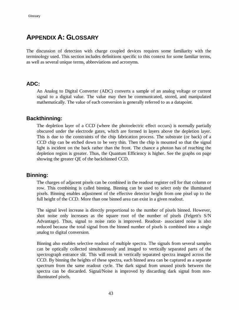
APPENDIX A: GLOSSARY The discussion of detection with charge coupled devices requires some familiarity with the terminology used. This section includes definitions specific to this context for some familiar terms, as well as several unique terms, abbreviations and acronyms.
ADC: An Analog to Digital Converter (ADC) converts a sample of an analog voltage or current signal to a digital value. The value may then be communicated, stored, and manipulated mathematically. The value of each conversion is generally referred to as a datapoint.
Backthinning: The depletion layer of a CCD (where the photoelectric effect occurs) is normally partially obscured under the electrode gates, which are formed in layers above the depletion layer. This is due to the constraints of the chip fabrication process. The substrate (or back) of a CCD chip can be etched down to be very thin. Then the chip is mounted so that the signal light is incident on the back rather than the front. The chance a photon has of reaching the depletion region is greater. Thus, the Quantum Efficiency is higher. See the graphs on page showing the greater QE of the backthinned CCD.
Binning: The charges of adjacent pixels can be combined in the readout register cell for that column or row. This combining is called binning. Binning can be used to select only the illuminated pixels. Binning enables adjustment of the effective detector height from one pixel up to the full height of the CCD. More than one binned area can exist in a given readout.
The signal level increase is directly proportional to the number of pixels binned. However, shot noise only increases as the square root of the number of pixels (Felgett's S/N Advantage). Thus, signal to noise ratio is improved. Readout- associated noise is also reduced because the total signal from the binned number of pixels is combined into a single analog to digital conversion.
Binning also enables selective readout of multiple spectra. The signals from several samples can be optically collected simultaneously and imaged to vertically separated parts of the spectrograph entrance slit. This will result in vertically separated spectra imaged across the CCD. By binning the heights of these spectra, each binned area can be captured as a separate spectrum from the same readout cycle. The dark signal from unused pixels between the spectra can be discarded. Signal/Noise is improved by discarding dark signal from non-illuminated pixels.

Glossary
44
Charge Coupled Device: The CCD is a solid state photodetector array made of silicon. It is essentially one continuous photosensitive material. Individual pixels or picture elements are defined by a grid of three electrode gates in the X and Y directions. The charge is collected under the gate with the greatest potential. During the readout cycle, the voltages applied to the gate electrodes are manipulated to move the charge across the pixels to the output register at the edge of the array. In contrast, PMT’s and other single channel detectors can measure only one intensity at a time. PDA detectors measure both intensity and wavelength. The CCD simultaneously measures intensity, wavelength and position differences projected along the height of the spectrograph image plane.
Charge Transfer Efficiency (CTE): The percentage of charge moved from one pixel to the next is the charge transfer efficiency. The CCD has a high CTE if the pixels are read out slowly. As the speed at which the charge is transferred is increased, increasing amounts of the charge is left behind. The residual charge combines with the charge of the next pixel as it is moved into the cell. Therefore, using too high a transfer rate deforms the image shape; it smears the charge over the pixels that follow in the readout cycle. Temperature also affects CTE. Below -140°C the movement of the charges becomes sluggish, and, again, the image becomes smeared.
Correlated Double Sampling: This is a technique used to increase the signal to noise ratio of each datapoint detected. Minute charges are unavoidably retained in the readout register between one sample and the next. Even though the readout register is reset after each point is read, some charge will persist. At the extremely low signal levels that are typical for cooled CCD detection, these charges are significant. By sampling this retained charge, amplifying and inverting it, it can be canceled by combining it with the actual signal which is amplified, but not inverted. The combined signal is then passed to the ADC to be processed as a datapoint. This process ensures that only the charge due to the signal in each pixel is measured.
Cosmic Ray Events: Cosmic Rays are high energy particles from the sun. Although they penetrate all detectors, their effect usually is masked by dark current. The dark signal of an LN2 cooled CCD is so low that cosmic rays may be detected. In the active area of a typical array, about 10 events per minute may occur. Compared to very weak signals, detected cosmic ray events can be quite distracting. To minimize the effects of cosmic rays, one can use the smallest section of the chip that the experiment allows, and use the least integration time possible. Variable Gain can help to reveal weak signals. Mathematical treatment of the data can also be used to

Glossary
45
remove the spurious spikes in spectra. Refer to the software manual for more about cosmic ray spike removal.
Dark Signal: Dark signal is generated by thermal agitation. This signal is directly related to exposure time and increases with temperature. The dark signal doubles with every 7oC increase in chip temperature above -25oC. The more dark signal, the less dynamic range for experimental signal. This signal accumulates for the entire time between readouts or flushes, regardless of whether the shutter is open or closed. Dark signal is also generated during the charge transfer cycles of the CCD.
Dynamic Range: The Dynamic Range is the ratio of the maximum and minimum signal measurable. The dynamic range of the chip can be greater than that of the system which is limited by the ADC. A 16 bit ADC limit is 65,535 (216-1) counts. A 14 bit ADC is limited to 16,383 counts. Variable Gain can be used to shift the ADC range to match the potential well capacity or signal levels of a given spectral measurement. In this way, stronger or weaker signals can be accommodated with optimal Dynamic Range.
On a pixel by pixel basis, the most intense detectable signal, the saturation level, is the lesser of the Potential Well Capacity of the pixel or the ADC maximum limit. When pixels are binned, individual pixels within a binned area may saturate if the intensity is concentrated. Also, the well capacity of the readout register will limit the total signal that can be binned from a given row or column of a binned area.
The weakest detectable signal is limited by the Dark Level plus the Readout Noise.
Electrons/Count: Electrons per count is a value indicating how many electrons are needed to be identified by the ADC as the smallest measurable unit, or Count. The total “Counts” of a given datapoint are comprised of electrons from a variety of sources, including: Photoelectrons (signal), Dark Level, Read Out Noise, Bias Level, and Amplifier Noise.
Felgett's Advantage: Multichannel detection provides an improvement in signal to noise ratio, as compared to single channel (scanned) spectral detection. Because the multichannel detection acquires a number of spectral elements simultaneously, the S/N is improved by a factor proportional to the square root of the number of channels acquired.

Glossary
46
Flush: To reduce noise and maximize dynamic range at the CCD, the dark charge that has accumulated on the chip can be rapidly removed by flushing. The effect of flushing the array is similar to a readout cycle in that the charges are cleared from the pixels. But a flush dumps the charges without conversion. A flush is much faster than a readout. Flushing is only necessary when there is an appreciable time between readouts.
Full Well Capacity: Full well capacity is the measure of how much charge can be stored in an individual pixel. This specification varies for each chip type. It depends on the doping of the silicon, architecture and pixel size. The quantum well capacity is usually around 300,000 electrons. The greater the well, the greater the Dynamic Range. A chip with a larger full well capacity can record a higher signal level before saturating. See also Variable Gain.
Linearity: When photo response is linear, if the light intensity doubles, the detected signal will double in magnitude as well. Nonlinear response at medium to high intensities is usually due to amplifier problems, and at very low light levels poor charge transfer efficiency. A CCD’s response is linear, once the bias is subtracted. Another definition of linearity is applied to the spectral positioning accuracy or tracking error of a spectrometer drive mechanism.
Noise: Noise is common to all detectors. The total amount of signal that exists is less important than the ratio of signal magnitude to noise magnitude (S/N). With a high signal to noise ratio a signal peak can be discerned even though signal counts per second may be low. The noise components for CCD arrays are as follows:
Amplifier Noise: Some noise is introduced in the process of electronically amplifying and conditioning the signal read from the detector before conversion to a digital value. Part of Readout Noise.
Conversion Noise: During the conversion of an analog signal to a digital datapoint some electronic noise is introduced, statistical variations occur in the least significant bit of the converted data. Part of Readout Noise.
Dark Noise: The detector will integrate a thermally generated Dark Current at all times, whether light is reaching the detector or not. Most of the dark current signal is a steady state level that can be subtracted, and so will not ultimately contribute to the noise. However, a component of Dark Current is Dark Noise due to statistical variations in the Dark Current. The Dark Noise component increases as the square root of the Dark Current. Dark Current, and therefore Dark Noise, can be reduced by cooling. The LN2 cooled CCD is one of the

Glossary
47
least noisy detectors available, with less than one electron/pixel/hour of dark signal. If the signal level is below saturation, increasing the signal integration time per readout will minimize the effect that dark noise has on the acquired signal. If the signal level is too high, summing multiple reads can give similar improvement. (See Readout Noise below.)
Readout Noise: The electronic noise impressed on the signal during the readout and digitizing of the signal. For convenience, usually all of the noise associated with resetting, amplifying, and converting the signal are considered as readout noise. When averaging signal by acquiring over a long interval of time, increasing the signal integration time per readout rather than summing multiple readouts is preferred. This will proportionately reduce the readout noise component in the acquired signal. However, the integration time must be short enough to prevent saturation of any individual pixels and to keep the digital signal for any datapoint below the ADC limit.
Reset Noise: Following pixel or bin readout, the readout register is reset to a level approaching zero charge. Reset Noise is the non-uniformity in the resetting. This is canceled by Correlated Double Sampling. Part of Readout Noise.
Shot Noise: This is due to the random statistical variations of light. It includes both experimental and dark signal components. Shot noise is equal to the square root of the number of electrons generated. Its effect can be minimized by increasing signal intensity, signal integration time, or summing a number of readouts.
Photoelectric Effect: Some materials respond to illumination from photons by releasing electrons. When light of sufficient energy hits a photosensitive material, an electron is freed from being bound to a specific atom. Such materials include the P-N junctions of the silicon photodiodes used in CCD arrays. The energy of the light must be greater than or equal to the binding energy of the electron to free an electron. The shorter the wavelength, the higher the energy the light has.
Photoelectron A photoelectron is an electron that is released through the interaction of a photon with the active element of a detector. The photoelectron could be released either from a junction to the conduction band of a solid state detector, or from the photocathode to the vacuum in a PMT. A photoelectron is indistinguishable from other electrons in any electrical circuit.
Photo Response NonUniformity (PRNU) PRNU is the peak to peak difference in response between the most and least sensitive elements of an array detector, under a uniform exposure giving an output level of VSat/2. These differences are primarily caused by variations in doping and silicon thickness.

Glossary
48
Quantum Efficiency (QE): The efficiency of the photoelectric effect of a detector can be quantified. The quantum efficiency of a detector is the ratio of number of photoelectrons produced to the number of photons impinging on a photoactive surface. A QE of 20% would indicate that one photon in five would produce a distinguishable photoelectron. CCD’s are made of silicon which has a high QE, about 45-50% at its peak at 750 nm. The quantum efficiency of a detector is determined by several factors. These include the material's intrinsic electron binding energy or band gap, the reflectivity of the surface, the thickness of the surface, and energy of the impinging photon (h ). The QE varies with the wavelength of incident light. Standard CCD’s typically have a peak QE of about 50%. Back thinned CCD’s may peak at about 85%. The QE at short wavelengths can be improved by coating with fluorescent dye that converts UV light to longer wavelengths where the quantum efficiency of the chip is higher. The graphs on page 14 show the QE of several available CCD’s.
Readout Time: The Readout Time of a CCD is the interval required to move the charges from their locations in the array to the readout registers, sample the charges, amplify them and convert them to datapoints. A consideration with a CCD is that the time between sample exposures can be longer than linear array detectors. This is because the readout requires that the charges be moved across the array (charge coupled). Also, the correlated double sampling readout technique requires more time per pixel.
Responsivity Responsivity is the ratio of output voltage to corresponding exposure (µJ/cm2). Technically it is measured at VSat min/2 under specified conditions of illumination, readout rate, and temperature.
Saturation Level The maximum signal level that can be accommodated by a device is its saturation level. At this point, further increase in input signal do not result in a corresponding increase in output. This term is often used to describe the upper limit of a detector element, an amplifier, or an ADC.
Spectral Response: Most detectors will respond with higher sensitivity to some wavelengths than to others. The spectral response of a detector is often expressed graphically in a plot of responsivity versus wavelength.

Glossary
49
UV Overcoating (Enhancement): Although silicon junctions release photoelectrons when illuminated with UV light, the depth of penetration into the silicon is very shallow. With this shallow penetration, the probability of a UV photon penetrating to the depletion zone is less than for longer wavelength photons. Thus the QE is lower in the UV than in the visible and NIR. By coating the chip with a fluorescent dye that converts UV light to longer wavelengths, the probability of photon detection is increased. This is because the longer wavelength photons emitted by the excited dye are able to penetrate to the depletion layer of the CCD.
Variable Gain: If a CCD has a quantum efficiency of 50%, then with two incident photons, a chip would produce one electron. With an electronic signal gain that produces one ADC count per electron, the system can measure that single electron, or two photons. If one ADC count equates to four electrons, then eight photons would be needed to produce those four measurable electrons, and thus one count. With a higher gain, one e-/count, the ability to resolve weak signals close to the noise level is increased. This is extremely important in applications such as Raman, where signals are typically very weak. By increasing the gain to measure signal levels which are very close to the noise, one can improve the signal to noise ratio while maintaining the same integration time. Or, one can achieve the same signal to noise ratio in less time.
A low gain has its applications as well. It is useful for preserving the full dynamic range of the CCD chip when measuring more intense signal levels. With a 16 bit ADC and one count equaling one electron, the ADC can only count a total of 65,000 electrons (with QE=50%, 130,000 photons). When the one ADC count equals four electrons, the 16 bit ADC counts to a maximum of 4 x 65,000 or about 250,000 electrons (500,000 photons) which is close to the full well capacity of the chip.
Variable Gain is needed to allow optimization between maximum sensitivity and full chip dynamic range. It allows trading off the ability to distinguish a small signal from noise in order to increase the highest signal level measurable, or vice versa.

Glossary
50
APPENDIX B: AC POWER SELECTION AND FUSING The power input module combines the line voltage selection, fuse holder, on / off switch and power line cord entry into one compact unit. To change the main power fuse, disconnect the line cord and pry the cover open. The fuse will come out in a cartridge with the cover. Printed on the cover are voltage ranges followed by a small arrow. The fuse for that voltage range is located on the same side of the cartridge as the arrow. Once the fuse is replaced, insert the cartridge so that the arrow next to the voltage range being used lines up with the small white dash on the controller. Circuit Line Voltage Fuse rating (3AG type) Input Power 100 VAC 2 Amp slow blow 120 VAC 2 Amp slow blow 220 VAC 1 Amp slow blow 240 VAC 1 Amp slow blow Shutter Fuse N/A 1 Amp fast blow

PC Communications Card Address, IRQ, and DMA Jumpers
51
APPENDIX C: PC COMMUNICATIONS CARD ADDRESS, IRQ, AND DMA JUMPERS Normally, the default jumper settings from the factory will allow use of the PC interface card without conflict. If problems are encountered, the jumper settings required to change the DMA channel, the Address, and IRQ setting are shown below.
P902 IRQ Selection (Default: 5)
IRQ Jumpered Pins 2 11 to 12 3 9 to 10 4 7 to 8 5 5 to 6 6 3 to 4 7 1 to 2
1
A31 A1
1
1
1
1
P902 IRQ
P5 Address
P901 DREQ
P900 Dack
DMA
Chan
nel
Figure 18: PC Interface Jumper Locations

PC Communications Card Address, IRQ, and DMA Jumpers
52
P5 Controller board Address
Selection (Default: E20)
Address Pins 1-2 Pins 3-4 Pins 5-6 INVALID Short Short Short
220 Short Short Open 620 Short Open Short A20 Short Open Open E20 Open Short Short 1220 Open Short Open 1620 Open Open Short 1A20 Open Open Open
DMA Channel Selection
(Default: 1)
DMA Channel DREQ Jumper P901
DACK Jumper P900
DMA1 5 to 6 5 to 6 DMA2 3 to 4 3 to 4 DMA3 1 to 2 1 to 2

PC Communications Card Address, IRQ, and DMA Jumpers
53
APPENDIX D: INTERFACE DRAWINGS:
.313
FOCALPLANE
.094
2.62
5
4.00
0
SLOT 7/32 WIDE X1/2 LONG. 6 PLACESON 3.600 BOLT CIRCLE.
Figure 19: LN2 Head Mounting Flange MAN0099
35872
1/4-20 NC
SLOT 7/32 WIDE X1/2 LONG, 6 PLACESON 3.600 BOLT CIRCLE
15.00
4.00
8.25
Figure 20: 1 Liter Side Mount LN2 Dewar MAN0090

Interface Drawings
54
6"
15.0"
8.0"
Slot 7/32 wide x 1/2 long. 6places on 3.600 bolt circle
1/4 - 20NC
Figure 21: 2.8 Liter Side - Looking LN2 Dewar MAN0111

PC Communications Card Address, IRQ, and DMA Jumpers
55
6"
18.2
50
Figure 22: 2.8 Liter Down - Looking LN2 Dewar MAN0092
SLOT 7/32 WIDE X 3/4LONG 3 REQ'D AS SHOWNON 3.600 B.C.
4.00"
0.495"
1 11/16" 3 13/64"4 57/64"
5.00"
Figure 23: Air Cooled TE CCD Head
MAN0088

Interface Drawings
56
TOP TOP
9 PIN
25 P
IN
CC
D C
HIP
SLOT 7/32 WIDE X3/4 LONG 3 REQ'D AS SHOWNON 3.6000 B.C.
8-32 NC 3 EQ. SP.ON 3.6000 B.C.
VACUUMPORT
COOLANTPIPE DIA. 1/4
2.5"4.0"0.50
0.09"0.44"
5 1/8"5 7/16"
Figure 24: Water Cooled TE CCD Head
MAN0086
REF.TOP
0.52
1.50
3.09
1.59
4.00
Figure 25: Mini-TECCD interface MAN0110

Programming with CCDLOAD.EXE
57
APPENDIX E: CCDLOAD.EXE SOFTWARE DRIVER The Charge Coupled Device (CCD) detection system is provided with SpectraMax general purpose commercial software. For those cases where a more compact software or more specific functionality may be required, a software driver is provided to facilitate communication with the controller boards. With this driver, an experienced programmer will be able to write routines to control the CCD and acquire data with it. The Spectrum One CCD detection system is compatible with the IBM PC/AT bus. The RISC interface card plugs into a slot in the host PC. The software, including the CCD driver are loaded from a floppy diskette. Refer to the SpectraMax Software Manual shipped with the system for installation instructions. This section of the manual outlines the driver calls that are available to controlling programs. The CCDLOAD.EXE driver is a low level interface to software that user-programmers may create. This driver is used by and included with SpectraMax software. Writing programs utilizing device drivers such as CCDLOAD.EXE requires considerable programming skill, and is therefore not recommended for the occasional or novice programmer. Teaching the skill of programming is beyond the scope of this document. To avoid confusion, it is best to be sure that the hardware is installed properly and that the system is functioning normally first, then proceed to writing, testing, and debugging a new program. Please complete the hardware and software installation and check out the system with SpectraMax before trying the new program. This manual covers the usage and protocol for the CCDLOAD.EXE driver calls. The calls will directly control the CCD and associated accessories. Note that spectrometer movements can be interfaced via a JY232/488 or SPEX232/488 control interface, not via CCDLOAD or CCD2000 controller.

Programming with CCDLOAD.EXE
58
Contents of CCDLOAD Appendix: System Hardware Requirements for CCDLOAD.EXE ............................................................59 Installation..............................................................................................................................59 List of Files.............................................................................................................................60 Summary of CCD Driver Calls................................................................................................61 Microsoft C Example Call to the CCD Driver .........................................................................63 Microsoft C Examples of Function Calls .................................................................................65 Definitions of Numbered Codes ..............................................................................................74 Type Definitions .....................................................................................................................76 Production Code Examples.....................................................................................................79

Programming with CCDLOAD.EXE
59
System Hardware Requirements for CCDLOAD.EXE: To support the CCDLOAD .EXE driver, the following hardware is required:
IBM compatible PC/ AT with a minimum of 64K conventional memory, a Hard disk drive, and a floppy drive to load the program
The PC bus speed must be 8 MHz
1½ full length, full height PC/ AT expansion card slot is required to mount the RISC interface boards
A math coprocessor is not required
The Driver has been tested on systems up to a Pentium 90Mhz.
Installation: This section assumes that the CCD hardware and SpectraMax software installation and checkout have been completed successfully. On that basis, one can proceed with confidence in the proper functioning of the detector electronics. In order to use the CCD Driver, first it must be loaded. This is accomplished by typing CCDLOAD at the DOS prompt. All the parameters are optional, any or all of them can be omitted. The sequence and case are unimportant. Syntax is as follows:
ccdload [/ppath] [/e] [/?] [/{i|f|h}nnn] [/u] [/d3] Where:
/p this is the DOS path to the initialization files /e turns on the emulate hardware mode, the CCD controller need not be connected /? shows syntax requirements, echoed to the screen /f nnn is the software interrupt to be used, disregarding any conflict with others already
in use. /i nnn is the software interrupt to be used, but if conflicting with previous interrupt
assignment, driver will not load /u unloads previously loaded copy of CCDLOAD, restoring memory to the system. If
the driver was loaded with a specified interrupt vector be sure to unload using the same interrupt vector. If any other Terminate and Stay Resident (TSR) programs are loaded after CCDLOAD, the driver program will not unload itself.

Programming with CCDLOAD.EXE
60
/d sets the DMA channel; default is 1, if necessary use the /d3 switch to set to channel 3 only
/h nnn sets the hardware interrupt The driver hooks the DOS equipment list when loaded and the driver interrupt used can be obtained from a call to is_driver_loaded ( int service_id ) as defined on page in the code example section. Upon loading, the driver reads the following files which must be in the current directory:
List of Files: File: Contains: CCDLOAD.INI Chip & controller specific information CCD.INB Voltage settings FLUSH32.D RISC code file CSETTEMP.D RISC code file CTEMPS.D RISC code file SHUT32.D RISC code file C578COL.D RISC code file CSHUTTER.D RISC code file OSHUTTER.D RISC code file NOTE: If the batch file HWINIT.BAT is used from time to time to optimize the chip, unload
and then re-load the driver so that it reads the updated information.

Programming with CCDLOAD.EXE
61
Summary of CCD Driver Calls:
(Decimal) # Function Name Use 0 DRV_INITIALIZE Initialize the Driver 1 DRV_TIMEOUT set a t/o for comm. init 2 HW_INITIALIZE force init and set flag 3 READ_HW_INIT_STATUS check if init flag is set 4 INITIALIZE_BUSY check if received confirm after init 300 CCD_INIT Initialize CCD hardware 301 CCD_SET_EXPOSURE_TIME Sets the exposure time 302 CCD_SET_GAIN Set the gain 303 CCD_READ_GAIN Returns the current gain setting 304 CCD_SET_AREAS Sets acq format, areas, data pointers, returns size of acquisition buffer(s) needed 305 CCD_SET_NUMBER_OF_FLUSHS Sets the number of flushes 306 CCD_SET_DOUBLE_COR_TIME Sets the double correlation time 307 CCD_SET_TEMPERATURE Sets the CCD temperature 308 CCD_READ_TEMPERATURE Returns the current CCD temperature 310 CCD_READ_CHIP_STUFF Returns CCD chip specific info 311 CCD_GO Starts an acquisition 314 CCD_STOP Stops any CCD operation in process 322 CCD_GO_BLANK Starts a blank acquisition (shutter closed) 312 CCD_BUSY Tests if acquisition is busy

Programming with CCDLOAD.EXE
62
315 CCD_READ_IMAGE Transfers next serial row of image data 316 CCD_READ_SCAN Transfers scan area data 317 CCD_RESET_IMAGE Sets image transfer back to 1st serial row 318 CCD_RESET_SCAN Sets area transfer back to 1st area 319 CCD_READ_NEXT_SCAN Transfers next area of scan data 320 CCD_OPEN_SHUTTER Opens the CCD shutter 321 CCD_CLOSE_SHUTTER Closes the CCD shutter 190 COMMUTATION_INIT Initialize a commutation device 191 COMMUTATION_SETUP Setup up for a commutation movement 192 COMMUTATION_GO Move the commutation device 195 COMMUTATION_STATUS Determine the status of a commutation device

Programming with CCDLOAD.EXE
63
Microsoft C Example Call to the CCD Driver: Note: The following macros are defined by Microsoft C in the DOS.H file: FP_SEG, FP_OFF, REGS, and SREGS. in Microsoft C version 5.1. This is the version used in this example. For version 7., Microsoft changed the definitions to _FP_SEG, _FP_OFF, _REGS, and _SREGS To prevent errors in compiling, make these changes. To make an interrupt call in other programming languages or other versions of C , See the documentation provided with the language or version in use. #define CCD_DRIVER 0xA2 Global int driver_interrupt; driver_interrupt = is_driver_loaded( CCD_DRIVER ); /* interrupt at which CCDLOAD is hooked to */ /* This was either specified on command line when CCDLOAD was loaded or was determined at load time to be the first free interrupt found. */ #include <dos.h> int is_driver_loaded( int service_id ) { union REGS intregs; struct SREGS intsregs; intregs.h.ah = (unsigned char)service_id; intregs.x.bx = 0; (void) int86x( 0x11, &intregs, &intregs, &intsregs); return( intregs.x.bx ); } //------------------------------------------------------------------------- void far *ccddriver( word command , void *param_ptr ) { /* uses global driver_interrupt */ void far *result_ptr; unsigned tseg, toff;

Programming with CCDLOAD.EXE
64
union REGS intregs; struct SREGS intsregs; /* obtain segment and offset of parameter block */ tseg = FP_SEG( param_ptr ); toff = FP_OFF( param_ptr ); /* pass segment and pointer in ds and dx */ intsregs.ds = tseg; intregs.x.dx = toff; /* command is passed in ax */ intregs.x.ax = command; (void) int86x(driver_interrupt, &intregs, &intregs, &intsregs); /* ax is non-zero if an error occurred in the driver */ if ( intregs.x.ax ) { /* Error routine goes here */ /* See (Appendix A) for possible error codes */ } /* ds and dx contain the segment and offset of the result pointer */ tseg = intsregs.ds; toff = intregs.x.dx; /* make a pointer for the return */ result_ptr = MK_FP( tseg , toff ); return( result_ptr ); }

Programming with CCDLOAD.EXE
65
Microsoft C Examples of Function Calls: //--------------------------------------------------------------------- Function: DRV_INITIALIZE 0 Example: typedef struct { char version[16]; /* driver version */ char id[16]; /* driver id */ } driver_parms; driver_parms *drvparms; drvparms = ( driver_parms *) ccddriver( DRV_INITIALIZE, NULL ); Explanation: This function initializes the driver, and returns the driver version and driver id, it must be called prior to any other driver calls to verify the version. //------------------------------------------------------------------------- Function: CCD_INIT 300 Example: byte ccd_number = 1; int ccd_hardware; ccd_hardware = *( int *) ccddriver( CCD_INIT, &ccd_number ); Explanation: Initializes CCD hardware; returns TRUE if hardware is present FALSE otherwise. If hardware is not detected the driver will perform hardware emulation as much as possible which is very useful for software testing. //------------------------------------------------------------------------- Function: CCD_SET_EXPOSURE_TIME 301 Example: byte_long ccd_pass; ccd_pass.byte0 = 1; /* ccd number */ ccd_pass.long0 = 1000L; /* time in milliseconds */ ( void ) ccddriver( DRV_SET_EXPOSURE_TIME, &ccd_pass ); Explanation: This function sets the time in milliseconds which will be used for all subsequent acquisitions.

Programming with CCDLOAD.EXE
66
//------------------------------------------------------------------------- Function: CCD_SET_GAIN 302 Example: byte_word ccd_pass; ccd_pass.byte0 = 1; /* ccd number */ ccd_pass.word0 = 1; /* gain */ ( void ) ccddriver( CCD_SET_GAIN , &ccd_pass ); Explanation: Sets the CCD gain. //------------------------------------------------------------------------- Function: CCD_READ_GAIN 303 Example: byte ccd_number = 1; int gain; gain = *(int *) ccddriver( CCD_READ_GAIN, &ccd_number ); Explanation: Returns the current gain setting. //------------------------------------------------------------------------- Function: CCD_SET_AREAS 304 Example: int acq_size; ccd_user_struct ccd_user_data; acq_size = *(int *) ccddriver( CCD_SET_AREAS, &ccd_user_data ); Explanation: Provides pointers to user data areas. "ccd_user_data" must always be available after this call. User data buffer(s) must be at least "acq_size" integers in length. NOTE: CCD_SET_AREAS sets "my_areas[0...number_of_areas].data_ptr" to NULL The program must now assign them to point to the data spaces allocated. See "ccd_user_struct" for details.

Programming with CCDLOAD.EXE
67
//------------------------------------------------------------------------- Function: CCD_SET_NUMBER_OF_FLUSHS 305 Example: byte_word ccd_pass; ccd_pass.byte0 = 1; /* ccd number */ ccd_pass.word0 = 1; /* number of flushs */ ( void ) ccddriver( CCD_SET_NUMBER_OF_FLUSHS, &ccd_pass ); Explanation: Sets the number of flushes of the CCD which will occur prior to starting an acquisition. //------------------------------------------------------------------------- Function: CCD_SET_DOUBLE_COR_TIME 306 Example: byte_word ccd_pass; ccd_pass.byte0 = 1; /* ccd number */ ccd_pass.word0 = 23; /* double correlation time */ ( void ) ccddriver( CCD_SET_DOUBLE_COR_TIME, &ccd_pass ); Explanation: Resets the double correlation time. The units are clock cycles = 1/6 microsecond. See CCD user manual for details. //------------------------------------------------------------------------- Function: CCD_SET_TEMPERATURE 307 Example: byte_word ccd_pass; ccd_pass.byte0 = 1; /* ccd number */ ccd_pass.long0 = 0; /* temperature in deg K */ ( void ) ccddriver( CCD_SET_TEMPERATURE, &ccd_pass ); Explanation: Sets the CCD to the temperature requested in degrees K. Use CCD_READ_TEMPERATURE to determine stability; this typicaly takes 20 minutes. NOTE: Reinitialize with HWINIT.BAT after a temperature change. This implies that the driver should be unloaded and reloaded to read new HWINIT parameters written to CCD.INB.

Programming with CCDLOAD.EXE
68
//------------------------------------------------------------------------- Function: CCD_READ_TEMPERATURE 308 Example: byte ccd_number = 1; int temperature_1; temperature_1 = *(long *) ccddriver( CCD_READ_TEMPERATURE, &ccd_number ); Explanation: Returns the CCD head temperature in degrees K. //------------------------------------------------------------------------- Function: CCD_READ_CHIP_STUFF 310 Example: ccd_tsr_struct chip_data; chip_data.ccd_number = 1; ( void )ccddriver( CCD_READ_CHIP_STUFF,&chip_data ); Explanation: Returns hardware specific information. See "ccd_tsr_struct" starting on page for details. //------------------------------------------------------------------------- Function: CCD_GO 311 Example: byte ccd_number = 1; ( void ) ccddriver( CCD_GO, &ccd_number ); Explanation: Starts the data acquisition sequence of: close shutter, perform number_of_flushes start integration - open shutter,integrate, close shutter transfer data from chip to RISC memory NOTE: The actual execution of this sequence relies on calls to CCD_BUSY; //------------------------------------------------------------------------- Function: CCD_STOP 314 Example: byte ccd_number = 1; ( void ) ccddriver( CCD_STOP, &ccd_number );

Programming with CCDLOAD.EXE
69
Explanation: Stops any CCD operation in process //------------------------------------------------------------------------- Function: CCD_GO_BLANK 322 Example: byte ccd_number = 1; ( void ) ccddriver( CCD_GO_BLANK, &ccd_number ); Explanation: Starts the data acquisition sequence of: close shutter perform number_of_flushes start integration - integrate (Shutter is NOT opened) transfer data from chip to RISC memory NOTE: The actual execution of this sequence relies on calls to CCD_BUSY; //------------------------------------------------------------------------- Function: CCD_BUSY 312 Example: byte ccd_number = 1; int busy; busy = *(int *) ccddriver( CCD_BUSY, &ccd_number ); Explanation: Steps the CCD_GO sequence to the next state. Returns busy = next_state ( != 0 ) until done ( == 0 ). //------------------------------------------------------------------------- Function: CCD_READ_IMAGE 315 Example: byte ccd_number = 1; ( void ) ccddriver( CCD_READ_IMAGE, &ccd_number ); Explanation: Transfers 1 serial row of data into the storage area specified in "ccd_user_data". See CCD_SET_AREAS for details. The program must perform multiple calls to this function until the entire image is transfered.

Programming with CCDLOAD.EXE
70
//------------------------------------------------------------------------- Function: CCD_READ_SCAN 316 Example: byte_word area_number; area_number.byte0 = 1; /* CCD number */ area_number.word0 = -1; /* area number of -1 = read ALL areas */ ( void ) ccddriver( CCD_READ_SCAN, &area_number ); Explanation: Transfers data for "area_number" into user allocated storage specified in "ccd_user_data". If area_number = -1, ALL scan data will be transfered. NOTE: This function can be randomly addressed by "area_number" but speed may be sacrificed. NOTE: Transfer fastest if all of the storage is allocated at once and read ALL areas. See CCD_SET_AREAS for details. //------------------------------------------------------------------------- Function: CCD_RESET_IMAGE 317 Example: byte ccd_number = 1; ( void ) ccddriver( CCD_RESET_IMAGE, &ccd_number ); Explanation: Resets internal memory pointers so that the next call to CCD_READ_IMAGE will start at the begining of the image. This is useful for multiple reads of the data from RISC memory for display purposes etc. //------------------------------------------------------------------------- Function: CCD_RESET_SCAN 318 Example: byte ccd_number = 1; ( void ) ccddriver( CCD_RESET_SCAN, &ccd_number ); Explanation: Resets internal memory pointers so that the next call to CCD_READ_SCAN will start at the beginning of the 1st area. This is useful for multiple reads of the data from RISC memory for display purposes etc.

Programming with CCDLOAD.EXE
71
//------------------------------------------------------------------------- Function: CCD_READ_NEXT_SCAN 319 Example: byte ccd_number = 1; ( void ) ccddriver( CCD_READ_NEXT_SCAN, &ccd_number ); Explanation: Transfers data sequentialy from the next area into user allocated storage specified in "ccd_user_data". NOTE: This function returns data areas in sequence. The program must call CCD_RESET_SCAN first to initialize the internal area counter. NOTE: This method of data transfer is slower than if ALL areas are read at once (see CCD_READ_SCAN with area number = -1), but may be faster than calling CCD_READ_SCAN for 1 area at a time. The speed will depend upon the CCD chips physical read out register direction. See CCD_SET_AREAS for details. //------------------------------------------------------------------------- Function: CCD_OPEN_SHUTTER 320 Example: byte ccd_number = 1; ( void ) ccddriver( CCD_OPEN_SHUTTER, &ccd_number ); Explanation: Opens the CCD shutter. //------------------------------------------------------------------------- Function: CCD_CLOSE_SHUTTER 321 Example: byte ccd_number = 1; ( void ) ccddriver( CCD_CLOSE_SHUTTER, &ccd_number ); Explanation: Closes the CCD shutter. Commutations are a JY generalization of the OPEN/CLOSE shutter commands. If the programmer has experience programming with other JY/ISA/SPEX drivers they are the same with the CCD shutter being commutation number 1; if the programmer is not familiar with this convention these calls may be ignored.

Programming with CCDLOAD.EXE
72
//------------------------------------------------------------------------- Function: COMMUTATION_INIT 190 Example: (void) ccddriver( COMMUTATION_INIT, NULL ); Explanation: This function initializes the shutter driver calls. //------------------------------------------------------------------------- Function: COMMUTATION_SETUP 191 Example: typedef struct { byte byte0; word word0; word word1; word word2; word word3; word word4; } byte_multi_word; byte_multi_word shutter_parms; shutter_parms.byte0 = 1; /* Must always be 1 */ shutter_parms.word0 = SHUTTER; /* Type */ shutter_parms.word1 = 2; /* Number of possible states */ shutter_parms.word2 = SHUTTER_CLOSED; /* Requested State */ shutter_parms.word3 = 0; /* NOT_USED */ shutter_parms.word4 = 0; /* NOT_USED */ (void) ccddriver( COMMUTATION_SETUP, &shutter_parms ); Explanation: This function sets the parameters for next COMMUTATION_GO command to this device. The first 3 parameters must always be 1, 1, and 2, the fourth parameter is either 1 or 0 depending on whether it is necessary to open or close the shutter. //------------------------------------------------------------------------- Function: COMMUTATION_GO 192 Example: byte shutter_num; shutter_num = 1; /* Must always be 1 */ (void) ccddriver( COMMUTATION_GO, &shutter ); Explanation:

Programming with CCDLOAD.EXE
73
This function moves the shutter to the position specified by a previously executed COMMUTATION_SETUP command. //------------------------------------------------------------------------- Function: COMMUTATION_STATUS 195 Example: byte_multi_word shutter_status; unsigned char shutter_num; shutter_num = 1; /* Must always be 1 */ shutter_status = ccddriver( COMMUTATION_STATUS, &shutter_num ); Explanation: This function returns the current state of the shutter in the structure shutter_status.

Programming with CCDLOAD.EXE
74
Definitions of Numbered Codes:
Setup and Communications Error Codes NO_PROBLEM 0 HARDWARE_PROBLEM 1 FUNCTION_NOT_AVAILABLE 2 PARAMETER_PROBLEM 3 NOT_INITIALIZED 4 RECEIVE_ERROR 5 TRANSMIT_ERROR 6 BAD_CONFIRMATION 7 UNKNOWN_CONFIRMATION_ERROR 8 FRAMING_ERROR 9 PARITY_ERROR 10 OVERRUN_ERROR 11 COM_PORT_ERROR 12 BAUD_RATE_ERROR 13 COM_PARAM_ERROR 14 RCV_TIME_OUT_ERROR 15
CCD Low Level Error Codes: CCD_OK NO_PROBLEM CCD_NULL_USER_POINTER 20 CCD_NOT_ENOUGH_MEMORY 21 CCD_ALTPARAM 22 CCD_LOAD 23 CCD_READPROG 24 CCD_TIMEOUT 25 CCD_ZEROLOOP 26
Commutation Devices: SHUTTER_CCD 1
Commutation Types: SHUTTER_TYPE 1

Programming with CCDLOAD.EXE
75
Commutation States: SHUTTER_OPEN 1 SHUTTER_CLOSED 0
Commutation (Shutter) Function Numbers: COMMUTATION_INIT 190 COMMUTATION_SETUP 191 COMMUTATION_GO 192 COMMUTATION_STATUS 195
Acquisition Formats: Image_format 0 Region_format 1

Programming with CCDLOAD.EXE
76
Type Definitions: #pragma pack(1) typedef unsigned char byte; typedef unsigned int word; typedef struct { char version[16]; /* driver version */ char id[16]; /* driver id */ } driver_parms; typedef struct { byte byte0; byte byte1; } byte_byte; typedef struct { byte byte0; word word0; } byte_word; typedef struct { byte byte0; long long0; } byte_long; /*__For JY Commutations ___________________________________________________*/ typedef struct { byte byte0; word word0; word word1; word word2; word word3; word word4; } byte_multi_word; /*________________________________________________________________________*/ typedef struct { /* read from file: ccdload.ini */ byte ccd_number; int port; int total_active_x_pixels; int total_active_y_pixels; int num_serial_pxls_before_active; int num_serial_pxls_after_active; int num_parallel_rows_before_active;

Programming with CCDLOAD.EXE
77
int num_parallel_rows_after_active; byte register_loc_and_direction; /* 0, 90, 180, 270 degrees */ /* */ /* readout register location and direction */ /* add one from each of the following: */ /* register location = 0 left */ /* 1 top */ /* 2 right */ /* 3 bottom */ /* */ /* direction is relative to our standard configuration */ /* with the readout register in the left position */ /* direction = 0 clockwise */ /* 4 counter-clockwise */ /* */ /* */ /* ^ */ /* | Std Config 0 degrees 90 degrees */ /* *_________________________ **************************-> */ /* * | | | */ /* * | | | */ /* * | | | */ /* * | | | */ /* * 0 | | 1 | */ /* * | | | */ /* * | | | */ /* * | | | */ /* *________________________| |________________________| */ /* */ /* */ /* */ /* */ /* 180 degrees 270 degrees */ /* _________________________ ________________________ */ /* | * | | */ /* | * | | */ /* | * | | */ /* | * | | */ /* | 2 * | 3 | */ /* | * | | */ /* | * | | */ /* | * | | */ /* |________________________* <-************************** */ /* | */ /* V */ /* */ /* */ /* Reverse readout 0 degrees Reverse readout 90 degrees */ /* _________________________ <-************************** */ /* * | | | */ /* * | | | */ /* * | | | */ /* * | | | */ /* * 4 | | 5 | */ /* * | | | */ /* * | | | */ /* * | | | */ /* *________________________| |________________________| */ /* | */ /* V */

Programming with CCDLOAD.EXE
78
/* */ /* ^ */ /* Reverse readout 180 degrees | Reverse readout 270 degrees */ /* _________________________* ________________________ */ /* | * | | */ /* | * | | */ /* | * | | */ /* | * | | */ /* | 6 * | 7 | */ /* | * | | */ /* | * | | */ /* | * | | */ /* |________________________* **************************-> */ /* */ /* */ int min_temperature; int max_temperature; long min_shutter_time; long max_shutter_time; word min_gain; word max_gain; int h_pixel_spacing; int v_pixel_spacing; /* calculated in ccd_init from above info */ int total_parallel_pixels; /* includes all possible pixels */ int total_serial_pixels; /* includes all possible pixels */ /* read from file: ccd.inb */ /* may also be changed by a driver call */ word double_correl_integr_time; } ccd_tsr_struct; /*________________________________________________________________________*/ typedef struct { unsigned int *data_ptr; int x_origin, /* offset */ y_origin, /* offset */ size_x, /* width */ size_y, /* heigth */ bin_x, bin_y; } ccd_area_struct; /*________________________________________________________________________*/ typedef struct { /* passed in driver calls */ byte ccd_number; byte acquisition_format; /* image = 0, region(scan) = 1 */ int number_of_areas; /* when in region(scan) mode */ ccd_area_struct *area_ptr; } ccd_user_struct;

Programming with CCDLOAD.EXE
79
#pragma pack()

Programming with CCDLOAD.EXE
80
Production Code Examples: Included on the disk is a fully functional example program written in Microsoft Quick C. This program file is : QDCCD.C. Along with it are all the files necessary to build it. This should serve as a good starting point for a new program. #define CCD_REGISTER_LONG 0x01 #define MAX_USER_AREAS 10 /* User size; not limited in driver */ /* NOTE: MAX_USER_AREAS is a user parameter; the driver allocates any necessary storage based on number_of_areas */ void get_ccd_data( void ) { int busy, row, size_x, size_y, hardware, acq_size, rows_to_read; long time_out, end_time; typedef struct { char version[16]; /* driver version */ char id[16]; /* driver id */ } driver_parms; driver_parms *drvparms; byte ccd_number; byte_long ccd_exp_time; byte_word ccd_flushes; ccd_tsr_struct chip_data; ccd_user_struct my_data; ccd_area_struct my_areas[ MAX_USER_AREAS ]; word my_image_buff[ 2048 ]; drvparms = ccddriver( DRV_INITIALIZE, NULL ); ccd_number = 1; /* CCD number; always 1 */ hardware = *(int *)ccddriver( CCD_INIT, &ccd_number ); chip_data = (ccd_tsr_struct *)ccddriver(CCD_READ_CHIP_STUFF, &ccd_number); size_x = chip_data.total_active_x_pixels; size_y = chip_data.total_active_y_pixels; ccd_exp_time.byte0 = 1; /* CCD number; always 1 */ ccd_exp_time.long0 = exposure_time; ( void ) ccddriver( CCD_SET_EXPOSURE_TIME, &ccd_exp_time ); ccd_flushes.byte0 = 1; /* CCD number; always 1 */ ccd_flushes.word0 = number_of_flushes; ( void ) ccddriver( CCD_SET_NUMBER_OF_FLUSHS, &ccd_flushes ); my_data.ccd_number = 1; my_data.acquisition_format = 0; my_data.number_of_areas = 1;

Programming with CCDLOAD.EXE
81
my_data.area_ptr = my_areas; my_areas[0].x_origin = 0; my_areas[0].y_origin = 0; my_areas[0].size_x = size_x; my_areas[0].size_y = size_y; my_areas[0].bin_x = 1; my_areas[0].bin_y = 1; acq_size = *(int *) ccddriver( CCD_SET_AREAS, &my_data ); /* NOTE: CCD_SET_AREAS sets "my_areas[0].data_ptr" to NULL must now assign it to point to the data space allocated */ my_areas[0].data_ptr = my_image_buff; ( void ) ccddriver( CCD_GO, &ccd_number ); abort = FALSE; /* global user flag */ time_out = 2L * exposure_time; end_time = time_now() + time_out; /* time_now returns current time in millseconds as a long */ do { busy = *(int *) ccddriver( CCD_BUSY, &ccd_number ); if ( key_board_hit() ) /* process user input */ process_user_input(); if ( end_time < time_now() ) /* check for time out */ { display_an_error("Time Out", time_out ); abort = TRUE; break; } } while ( busy && !abort); /* abort can be set by user to cancel the current acquisition */ if ( abort ) /* user abort or time out */ return; if ( chip_data.register_loc_and_direction & CCD_REGISTER_LONG ) { rows_to_read = my_areas[0].size_y / my_areas[0].bin_y; } else { rows_to_read = my_areas[0].size_x / my_areas[0].bin_x; } /** Reset image transfer back to 1st serial row **/ ( void ) ccddriver(CCD_RESET_IMAGE, &ccd_number ); /* Now get each row (line) of the image */ for ( row = 0; row < rows_to_read ; row++ ) { /* get a row of data */ ( void ) ccddriver( CCD_READ_IMAGE, &ccd_number ); /* do something with "acq_size" points of data in "my_image_buff" */ } } //--------------------------------------------------------------------------

Programming with CCDLOAD.EXE
82

Programming with CCD3000.EXE
83
APPENDIX F: CCD3000.EXE SOFTWARE DRIVER The Charge Coupled Device (CCD) detection system is provided with either SpectraMax general purpose commercial software. For those cases where a more compact software or more specific functionality may be required, a software driver is provided to facilitate communication with the controller boards. With this driver, an experienced programmer will be able to write routines to control the CCD and acquire data with it. The Spectrum One CCD detection system with a CCD3000 controller is compatible with any computer using a National Instruments IEEE-488 card. The software, including the CCD driver are loaded from a floppy diskette works with an IBM PC compatible. Refer to the SpectraMax Software Manual shipped with the system for installation instructions. This section of the manual outlines the driver calls that are available to controlling programs. The CCD3000.EXE driver is a low level interface to software that user-programmers may create. This driver is used by and included with SpectraMax software. Writing programs utilizing device drivers such as CCD3000.EXE requires considerable programming skill, and is therefore not recommended for the occasional or novice programmer. Teaching the skill of programming is beyond the scope of this document. To avoid confusion, it is best to be sure that the hardware is installed properly and that the system is functioning normally first, then proceed to writing, testing, and debugging a new program. Please complete the hardware and software installation and check out the system with SpectraMax before trying the new program. This manual covers the usage and protocol for the CCD3000.EXE driver calls. The calls will directly control the CCD and associated accessories. Note that spectrometer movements can be interfaced via a JY232/488 or SPEX232/488 control interface, not via the CCD3000 controller or CCD3000.EXE.

Programming with CCD3000.EXE
84
Contents of CCD3000 Appendix: System Hardware Requirements for CCD3000.EXE..................................................................83 Installation.................................................................................................................................83 List of Files................................................................................................................................84 Summary of CCD Driver Calls...................................................................................................85 Microsoft C Example Call to the CCD Driver ............................................................................87 Microsoft C Examples of Function Calls ....................................................................................89 Definitions of Numbered Codes .................................................................................................97 Type Definitions ........................................................................................................................99 Production Code Examples......................................................................................................102 Command Set Structure...........................................................................................................104

Programming with CCD3000.EXE
85
System Hardware Requirements for CCD3000.EXE: To support the CCD3000 .EXE driver, the following hardware is required:
IBM compatible PC/AT with a minimum of 64K conventional memory, a Hard disk drive, and a floppy drive to load the program
National Instruments IEEE-488 communications card.
A coprocessor is not required
The driver has been tested on systems up to a Pentium 90Mhz.
Installation: This section assumes that the CCD hardware and SpectraMax software installation and checkout have been completed successfully. On that basis, one can proceed with confidence in the proper functioning of the detector electronics. In order to use the CCD Driver, first it must be loaded. This is accomplished by typing CCD3000 at the DOS prompt. All the parameters are optional, any or all of them can be omitted. The sequence and case are unimportant. Syntax is as follows:
ccd3000 [/?] [/u] [/devx] [/p] [/{i|f}nnn] Where:
/? shows syntax requirements, echoed to the screen /p this is the DOS path to the initialization files /f nnn is the software interrupt to be used, disregarding any conflict with others already
in use. /i nnn is the software interrupt to be used (default is search for available if neither /f or
/i is specified) /dev standard gpib device number, dev1, dev2 etc. (default dev5) /u unloads previously loaded copy of CCD3000, restoring memory to the system. If the
driver was loaded with a specified interrupt vector be sure to unload using the same interrupt vector. If any other Terminate and Stay Resident (TSR) programs are loaded after CCD3000, the driver program will not unload itself.
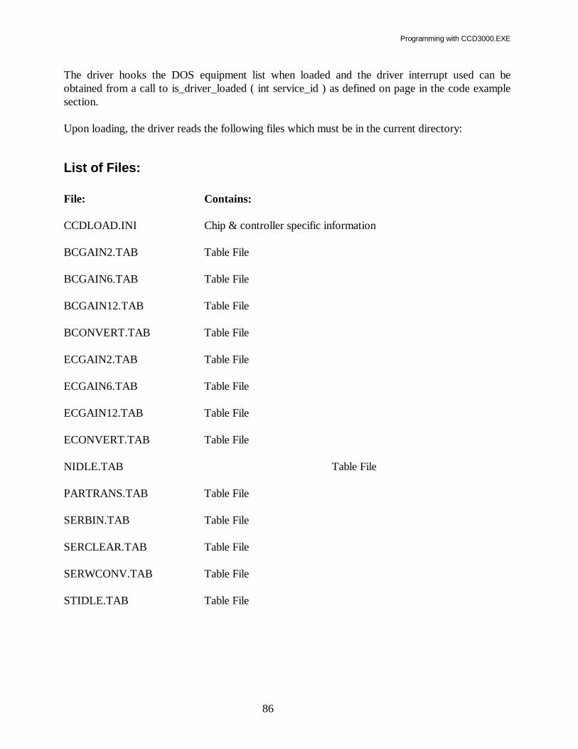
Programming with CCD3000.EXE
86
The driver hooks the DOS equipment list when loaded and the driver interrupt used can be obtained from a call to is_driver_loaded ( int service_id ) as defined on page in the code example section. Upon loading, the driver reads the following files which must be in the current directory:
List of Files: File: Contains: CCDLOAD.INI Chip & controller specific information BCGAIN2.TAB Table File BCGAIN6.TAB Table File BCGAIN12.TAB Table File BCONVERT.TAB Table File ECGAIN2.TAB Table File ECGAIN6.TAB Table File ECGAIN12.TAB Table File ECONVERT.TAB Table File NIDLE.TAB Table File PARTRANS.TAB Table File SERBIN.TAB Table File SERCLEAR.TAB Table File SERWCONV.TAB Table File STIDLE.TAB Table File

Programming with CCD3000.EXE
87
Summary of CCD Driver Calls: (Decimal)
# Function Name Use 0 DRV_INITIALIZE Initialize the Driver 1 DRV_TIMEOUT set a t/o for comm. init 2 HW_INITIALIZE force init and set flag 3 READ_HW_INIT_STATUS check if init flag is set 4 INITIALIZE_BUSY check if received confirm after init 300 CCD_INIT Initialize CCD hardware 301 CCD_SET_EXPOSURE_TIME Sets the exposure time 304 CCD_SET_AREAS Sets acq format, areas, data pointers, returns size of acquisition buffer(s) needed 307 CCD_SET_TEMPERATURE Sets the CCD temperature 308 CCD_READ_TEMPERATURE Returns the current CCD temperature 310 CCD_READ_CHIP_STUFF Returns CCD chip specific info 311 CCD_GO Starts an acquisition 314 CCD_STOP Stops any CCD operation in process 322 CCD_GO_BLANK Starts a blank acquisition (shutter closed) 312 CCD_BUSY Tests if acquisition is busy 315 CCD_READ_IMAGE Transfers next serial row of image data 316 CCD_READ_SCAN Transfers scan area data 317 CCD_RESET_IMAGE Sets image transfer back to 1st serial row 318 CCD_RESET_SCAN Sets area transfer back to 1st area

Programming with CCD3000.EXE
88
319 CCD_READ_NEXT_SCAN Transfers next area of scan data 320 CCD_OPEN_SHUTTER Opens the CCD shutter 321 CCD_CLOSE_SHUTTER Closes the CCD shutter 329 CCD_GO_BLAST Set the number of acquisitions in blast mode. 190 COMMUTATION_INIT Initialize a commutation device 191 COMMUTATION_SETUP Setup up for a commutation movement 192 COMMUTATION_GO Move the commutation device 195 COMMUTATION_STATUS Determine the status of a commutation device

Programming with CCD3000.EXE
89
Microsoft C Example Call to the CCD Driver: Note: The following macros are defined by Microsoft C in the DOS.H file: FP_SEG, FP_OFF, REGS, and SREGS. in Microsoft C version 5.1. This is the version used in this example. For version 7., Microsoft changed the definitions to _FP_SEG, _FP_OFF, _REGS, and _SREGS To prevent errors in compiling, make these changes. To make an interrupt call in other programming languages or other versions of C , See the documentation provided with the language or version in use. #define CCD_DRIVER 0xA2 Global int driver_interrupt; driver_interrupt = is_driver_loaded( CCD_DRIVER ); /* interrupt at which CCDLOAD is hooked to */ /* This was either specified on command line when CCDLOAD was loaded or was determined at load time to be the first free interrupt found. */ #include <dos.h> int is_driver_loaded( int service_id ) { union REGS intregs; struct SREGS intsregs; intregs.h.ah = (unsigned char)service_id; intregs.x.bx = 0; (void) int86x( 0x11, &intregs, &intregs, &intsregs); return( intregs.x.bx ); } //------------------------------------------------------------------------- void far *ccddriver( word command , void *param_ptr ) { /* uses global driver_interrupt */ void far *result_ptr; unsigned tseg, toff; union REGS intregs; struct SREGS intsregs;
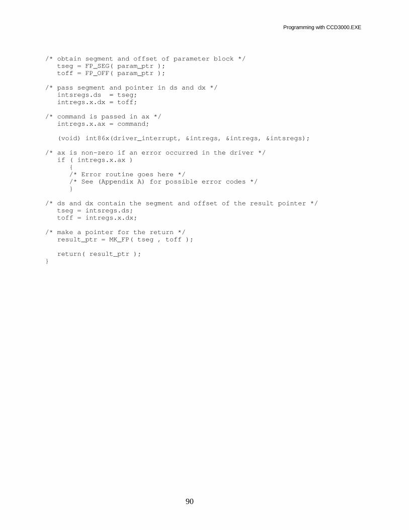
Programming with CCD3000.EXE
90
/* obtain segment and offset of parameter block */ tseg = FP_SEG( param_ptr ); toff = FP_OFF( param_ptr ); /* pass segment and pointer in ds and dx */ intsregs.ds = tseg; intregs.x.dx = toff; /* command is passed in ax */ intregs.x.ax = command; (void) int86x(driver_interrupt, &intregs, &intregs, &intsregs); /* ax is non-zero if an error occurred in the driver */ if ( intregs.x.ax ) { /* Error routine goes here */ /* See (Appendix A) for possible error codes */ } /* ds and dx contain the segment and offset of the result pointer */ tseg = intsregs.ds; toff = intregs.x.dx; /* make a pointer for the return */ result_ptr = MK_FP( tseg , toff ); return( result_ptr ); }

Programming with CCD3000.EXE
91
Microsoft C Examples of Function Calls: //------------------------------------------------------------------------- Function: DRV_INITIALIZE 0 Example: typedef struct { char version[16]; /* driver version */ char id[16]; /* driver id */ } driver_parms; driver_parms *drvparms; drvparms = ( driver_parms *) ccddriver( DRV_INITIALIZE, NULL ); Explanation: This function initializes the driver, and returns the driver version and driver id, it must be called prior to any other driver calls to verify the version. //------------------------------------------------------------- Function: CCD_INIT 300 Example: byte ccd_number = 1; int ccd_hardware; ccd_hardware = *( int *) ccddriver( CCD_INIT, &ccd_number ); Explanation: Initializes CCD hardware; returns TRUE if hardware is present FALSE otherwise. If hardware is not detected the driver will perform hardware emulation as much as possible which is very useful for software testing. //------------------------------------------------------------------------- Function: CCD_SET_EXPOSURE_TIME 301 Example: byte_long ccd_pass; ccd_pass.byte0 = 1; /* ccd number */ ccd_pass.long0 = 1000L; /* time in milliseconds */ ( void ) ccddriver( DRV_SET_EXPOSURE_TIME, &ccd_pass ); Explanation: This function sets the time in milliseconds which will be used for all subsequent acquisitions.

Programming with CCD3000.EXE
92
//------------------------------------------------------------------------- Function: CCD_SET_AREAS 304 Example: int acq_size; ccd_user_struct ccd_user_data; acq_size = *(int *) ccddriver( CCD_SET_AREAS, &ccd_user_data ); Explanation: Provides pointers to user data areas. "ccd_user_data" must always be available after this call. User data buffer(s) must be at least "acq_size" integers in length. NOTE: CCD_SET_AREAS sets "my_areas[0...number_of_areas].data_ptr" to NULL The program must now assign them to point to the data spaces allocated. See "ccd_user_struct" for details. //------------------------------------------------------------------------- Function: CCD_SET_TEMPERATURE 307 Example: byte_word ccd_pass; ccd_pass.byte0 = 1; /* ccd number */ ccd_pass.long0 = 0; /* temperature in deg K */ ( void ) ccddriver( CCD_SET_TEMPERATURE, &ccd_pass ); Explanation: Sets the CCD to the temperature requested in degrees K. Use CCD_READ_TEMPERATURE to determine stability; this typicaly takes 20 minutes. NOTE: Reinitialize with HWINIT.BAT after a temperature change. This implies that the driver should be unloaded and reloaded to read new HWINIT parameters written to CCD.INB. //------------------------------------------------------------------------- Function: CCD_READ_TEMPERATURE 308 Example: byte ccd_number = 1; int temperature_1; temperature_1 = *(long *) ccddriver( CCD_READ_TEMPERATURE, &ccd_number ); Explanation:

Programming with CCD3000.EXE
93
Returns the CCD head temperature in degrees K. //------------------------------------------------------------------------- Function: CCD_READ_CHIP_STUFF 310 Example: ccd_tsr_struct chip_data; chip_data.ccd_number = 1; ( void )ccddriver( CCD_READ_CHIP_STUFF,&chip_data ); Explanation: Returns hardware specific information. See "ccd_tsr_struct" starting on page for details. //------------------------------------------------------------------------- Function: CCD_GO 311 Example: byte ccd_number = 1; ( void ) ccddriver( CCD_GO, &ccd_number ); Explanation: Starts the data acquisition sequence of: close shutter, perform number_of_flushes start integration - open shutter,integrate, close shutter transfer data from chip to RISC memory NOTE: The actual execution of this sequence relies on calls to CCD_BUSY; //------------------------------------------------------------------------- Function: CCD_STOP 314 Example: byte ccd_number = 1; ( void ) ccddriver( CCD_STOP, &ccd_number ); Explanation: Stops any CCD operation in process //------------------------------------------------------------------------- Function: CCD_GO_BLANK 322 Example: byte ccd_number = 1;

Programming with CCD3000.EXE
94
( void ) ccddriver( CCD_GO_BLANK, &ccd_number ); Explanation: Starts the data acquisition sequence of: close shutter perform number_of_flushes start integration - integrate (Shutter is NOT opened) transfer data from chip to RISC memory NOTE: The actual execution of this sequence relies on calls to CCD_BUSY; //------------------------------------------------------------------------- Function: CCD_BUSY 312 Example: byte ccd_number = 1; int busy; busy = *(int *) ccddriver( CCD_BUSY, &ccd_number ); Explanation: Steps the CCD_GO sequence to the next state. Returns busy = next_state( != 0 ) until done ( == 0 ). //------------------------------------------------------------------------- Function: CCD_READ_IMAGE 315 Example: byte ccd_number = 1; ( void ) ccddriver( CCD_READ_IMAGE, &ccd_number ); Explanation: Transfers 1 serial row of data into the storage area specified in "ccd_user_data". See CCD_SET_AREAS for details. The program must perform multiple calls to this function until the entire image is transfered. //------------------------------------------------------------------------- Function: CCD_READ_SCAN 316 Example: byte_word area_number; area_number.byte0 = 1; /* CCD number */ area_number.word0 = -1; /* area number of -1 = read ALL areas */ ( void ) ccddriver( CCD_READ_SCAN, &area_number ); Explanation:

Programming with CCD3000.EXE
95
Transfers data for "area_number" into user allocated storage specified in "ccd_user_data". If area_number = -1, ALL scan data will be transfered. NOTE: This function can be randomly addressed by "area_number" but speed may be sacrificed. NOTE: Transfer fastest if all of the storage is allocated at once and read ALL areas. See CCD_SET_AREAS for details. //------------------------------------------------------------------------- Function: CCD_RESET_IMAGE 317 Example: byte ccd_number = 1; ( void ) ccddriver( CCD_RESET_IMAGE, &ccd_number ); Explanation: Resets internal memory pointers so that the next call to CCD_READ_IMAGE will start at the beginning of the image. This is useful for multiple reads of the data from RISC memory for display purposes etc. //------------------------------------------------------------------------- Function: CCD_RESET_SCAN 318 Example: byte ccd_number = 1; ( void ) ccddriver( CCD_RESET_SCAN, &ccd_number ); Explanation: Resets internal memory pointers so that the next call to CCD_READ_SCAN will start at the beginning of the 1st area. This is useful for multiple reads of the data from RISC memory for display purposes etc. //------------------------------------------------------------------------- Function: CCD_READ_NEXT_SCAN 319 Example: byte ccd_number = 1; ( void ) ccddriver( CCD_READ_NEXT_SCAN, &ccd_number ); Explanation: Transfers data sequentially from the next area into user allocated storage specified in "ccd_user_data". NOTE: This function returns data areas in sequence. The program must call CCD_RESET_SCAN first to initialize the internal area counter. NOTE: This method of data transfer is slower than if ALL areas are read at once (see CCD_READ_SCAN with area number = -1), but may be faster than calling

Programming with CCD3000.EXE
96
CCD_READ_SCAN for 1 area at a time. The speed will depend upon the CCD chips physical read out register direction. See CCD_SET_AREAS for details. //------------------------------------------------------------------------- Function: CCD_OPEN_SHUTTER 320 Example: byte ccd_number = 1; ( void ) ccddriver( CCD_OPEN_SHUTTER, &ccd_number ); Explanation: Opens the CCD shutter. //------------------------------------------------------------------------- Function: CCD_CLOSE_SHUTTER 321 Example: byte ccd_number = 1; ( void ) ccddriver( CCD_CLOSE_SHUTTER, &ccd_number ); Explanation: Closes the CCD shutter. Commutations are a JY generalization of the OPEN/CLOSE shutter commands. If the programmer has experience programming with other JY/ISA/SPEX drivers they are the same with the CCD shutter being commutation number 1; if the programmer is not familiar with this convention these calls may be ignored. //------------------------------------------------------------------------- Function: CCD_GO_BLAST 329 Example: byte_word ccd_pass; ccd_pass.byte0 = 1; /* ccd number */ ccd_pass.word0 = 1; /* number of blast cycles */ ( void ) ccddriver( CCD_GO_BLAST, &ccd_pass ); Explanation: Sets the number of acquisition for the CCD to acquire in blast mode. Once the CCD_GO_BLAST command has been sent, monitor the acquisition progress with CCD_BUSY. As soon as first blast acquisition is finished retrieve the data and reissue the CCD_BUSY command. //------------------------------------------------------------------------- Function: COMMUTATION_INIT 190

Programming with CCD3000.EXE
97
Example: (void) ccddriver( COMMUTATION_INIT, NULL ); Explanation: This function initializes the shutter driver calls. //------------------------------------------------------------------------- Function: COMMUTATION_SETUP 191 Example: typedef struct { byte byte0; word word0; word word1; word word2; word word3; word word4; } byte_multi_word; byte_multi_word shutter_parms; shutter_parms.byte0 = 1; /* Must always be 1 */ shutter_parms.word0 = SHUTTER; /* Type */ shutter_parms.word1 = 2; /* Number of possible states */ shutter_parms.word2 = SHUTTER_CLOSED; /* Requested State */ shutter_parms.word3 = 0; /* NOT_USED */ shutter_parms.word4 = 0; /* NOT_USED */ (void) ccddriver( COMMUTATION_SETUP, &shutter_parms ); Explanation: This function sets the parameters for next COMMUTATION_GO command to this device. The first 3 parameters must always be 1, 1, and 2, the fourth parameter is either 1 or 0 depending on whether it is necessary to open or close the shutter. //------------------------------------------------------------------------- Function: COMMUTATION_GO 192 Example: byte shutter_num; shutter_num = 1; /* Must always be 1 */ (void) ccddriver( COMMUTATION_GO, &shutter ); Explanation: This function moves the shutter to the position specified by a previously executed COMMUTATION_SETUP command. //-------------------------------------------------------------------------

Programming with CCD3000.EXE
98
Function: COMMUTATION_STATUS 195 Example: byte_multi_word shutter_status; unsigned char shutter_num; shutter_num = 1; /* Must always be 1 */ shutter_status = ccddriver( COMMUTATION_STATUS, &shutter_num ); Explanation: This function returns the current state of the shutter in the structure shutter_status.

Programming with CCD3000.EXE
99
Definitions of Numbered Codes:
Setup and Communications Error Codes NO_PROBLEM 0 HARDWARE_PROBLEM 1 FUNCTION_NOT_AVAILABLE 2 PARAMETER_PROBLEM 3 NOT_INITIALIZED 4 RECEIVE_ERROR 5 TRANSMIT_ERROR 6 BAD_CONFIRMATION 7 UNKNOWN_CONFIRMATION_ERROR 8 FRAMING_ERROR 9 PARITY_ERROR 10 OVERRUN_ERROR 11 COM_PORT_ERROR 12 BAUD_RATE_ERROR 13 COM_PARAM_ERROR 14 RCV_TIME_OUT_ERROR 15
CCD Low Level Error Codes: CCD_OK NO_PROBLEM CCD_NULL_USER_POINTER 20 CCD_NOT_ENOUGH_MEMORY 21 CCD_ALTPARAM 22 CCD_LOAD 23 CCD_READPROG 24 CCD_TIMEOUT 25 CCD_ZEROLOOP 26
Commutation Devices: SHUTTER_CCD 1
Commutation Types: SHUTTER_TYPE 1

Programming with CCD3000.EXE
100
Commutation States: SHUTTER_OPEN 1 SHUTTER_CLOSED 0
Commutation (Shutter) Function Numbers: COMMUTATION_INIT 190 COMMUTATION_SETUP 191 COMMUTATION_GO 192 COMMUTATION_STATUS 195
Acquisition Formats: Image_format 0 Region_format 1

Programming with CCD3000.EXE
101
Type Definitions: #pragma pack(1) typedef unsigned char byte; typedef unsigned int word; typedef struct { char version[16]; /* driver version */ char id[16]; /* driver id */ } driver_parms; typedef struct { byte byte0; byte byte1; } byte_byte; typedef struct { byte byte0; word word0; } byte_word; typedef struct { byte byte0; long long0; } byte_long; /*__For JY Commutations ___________________________________________________*/ typedef struct { byte byte0; word word0; word word1; word word2; word word3; word word4; } byte_multi_word; /*________________________________________________________________________*/ typedef struct { /* read from file: ccdload.ini */ byte ccd_number; int port; int total_active_x_pixels; int total_active_y_pixels; int num_serial_pxls_before_active; int num_serial_pxls_after_active; int num_parallel_rows_before_active;

Programming with CCD3000.EXE
102
int num_parallel_rows_after_active; byte register_loc_and_direction; /* 0, 90, 180, 270 degrees */ /* */ /* readout register location and direction */ /* add one from each of the following: */ /* register location = 0 left */ /* 1 top */ /* 2 right */ /* 3 bottom */ /* */ /* direction is relative to our standard configuration */ /* with the readout register in the left position */ /* direction = 0 clockwise */ /* 4 counter-clockwise */ /* */ /* */ /* ^ */ /* | Std Config 0 degrees 90 degrees */ /* *_________________________ **************************-> */ /* * | | | */ /* * | | | */ /* * | | | */ /* * | | | */ /* * 0 | | 1 | */ /* * | | | */ /* * | | | */ /* * | | | */ /* *________________________| |________________________| */ /* */ /* */ /* */ /* */ /* 180 degrees 270 degrees */ /* _________________________ ________________________ */ /* | * | | */ /* | * | | */ /* | * | | */ /* | * | | */ /* | 2 * | 3 | */ /* | * | | */ /* | * | | */ /* | * | | */ /* |________________________* <-************************** */ /* | */ /* V */ /* */ /* */ /* Reverse readout 0 degrees Reverse readout 90 degrees */ /* _________________________ <-************************** */ /* * | | | */ /* * | | | */ /* * | | | */ /* * | | | */ /* * 4 | | 5 | */ /* * | | | */ /* * | | | */ /* * | | | */ /* *________________________| |________________________| */ /* | */ /* V */

Programming with CCD3000.EXE
103
/* */ /* ^ */ /* Reverse readout 180 degrees | Reverse readout 270 degrees */ /* _________________________* ________________________ */ /* | * | | */ /* | * | | */ /* | * | | */ /* | * | | */ /* | 6 * | 7 | */ /* | * | | */ /* | * | | */ /* | * | | */ /* |________________________* **************************-> */ /* */ /* */ int min_temperature; int max_temperature; long min_shutter_time; long max_shutter_time; word min_gain; word max_gain; int h_pixel_spacing; int v_pixel_spacing; /* calculated in ccd_init from above info */ int total_parallel_pixels; /* includes all possible pixels */ int total_serial_pixels; /* includes all possible pixels */ /* read from file: ccd.inb */ /* may also be changed by a driver call */ word double_correl_integr_time; } ccd_tsr_struct; /*________________________________________________________________________*/ typedef struct { unsigned int *data_ptr; int x_origin, /* offset */ y_origin, /* offset */ size_x, /* width */ size_y, /* height */ bin_x, bin_y; } ccd_area_struct; /*________________________________________________________________________*/ typedef struct { /* passed in driver calls */ byte ccd_number; byte acquisition_format; /* image = 0, region(scan) = 1 */ int number_of_areas; /* when in region(scan) mode */ ccd_area_struct *area_ptr; } ccd_user_struct;

Programming with CCD3000.EXE
104
#pragma pack()

Programming with CCD3000.EXE
105
Production Code Examples: Included on the disk is a fully functional example program written in Microsoft Quick C. This program file is QDCCD.C. Along with it are all the files necessary to build it. This should serve as a good starting point for a new program. #define CCD_REGISTER_LONG 0x01 #define MAX_USER_AREAS 10 /* User size; not limited in driver */ /* NOTE: MAX_USER_AREAS is a user parameter; the driver allocates any necessary storage based on number_of_areas */ void get_ccd_data( void ) { int busy, row, size_x, size_y, hardware, acq_size, rows_to_read; long time_out, end_time; typedef struct { char version[16]; /* driver version */ char id[16]; /* driver id */ } driver_parms; driver_parms *drvparms; byte ccd_number; byte_long ccd_exp_time; byte_word ccd_flushes; ccd_tsr_struct chip_data; ccd_user_struct my_data; ccd_area_struct my_areas[ MAX_USER_AREAS ]; word my_image_buff[ 2048 ]; drvparms = ccddriver( DRV_INITIALIZE, NULL ); ccd_number = 1; /* CCD number; always 1 */ hardware = *(int *)ccddriver( CCD_INIT, &ccd_number ); chip_data = (ccd_tsr_struct *)ccddriver(CCD_READ_CHIP_STUFF, &ccd_number); size_x = chip_data.total_active_x_pixels; size_y = chip_data.total_active_y_pixels; ccd_exp_time.byte0 = 1; /* CCD number; always 1 */ ccd_exp_time.long0 = exposure_time; ( void ) ccddriver( CCD_SET_EXPOSURE_TIME, &ccd_exp_time ); ccd_flushes.byte0 = 1; /* CCD number; always 1 */ ccd_flushes.word0 = number_of_flushes; ( void ) ccddriver( CCD_SET_NUMBER_OF_FLUSHS, &ccd_flushes ); my_data.ccd_number = 1; my_data.acquisition_format = 0; my_data.number_of_areas = 1;

Programming with CCD3000.EXE
106
my_data.area_ptr = my_areas; my_areas[0].x_origin = 0; my_areas[0].y_origin = 0; my_areas[0].size_x = size_x; my_areas[0].size_y = size_y; my_areas[0].bin_x = 1; my_areas[0].bin_y = 1; acq_size = *(int *) ccddriver( CCD_SET_AREAS, &my_data ); /* NOTE: CCD_SET_AREAS sets "my_areas[0].data_ptr" to NULL must now assign it to point to the data space allocated */ my_areas[0].data_ptr = my_image_buff; ( void ) ccddriver( CCD_GO, &ccd_number ); abort = FALSE; /* global user flag */ time_out = 2L * exposure_time; end_time = time_now() + time_out; /* time_now returns current time in milliseconds as a long */ do { busy = *(int *) ccddriver( CCD_BUSY, &ccd_number ); if ( key_board_hit() ) /* process user input */ process_user_input(); if ( end_time < time_now() ) /* check for time out */ { display_an_error("Time Out", time_out ); abort = TRUE; break; } } while ( busy && !abort); /* abort can be set by user to cancel the current acquisition */ if ( abort ) /* user abort or time out */ return; if ( chip_data.register_loc_and_direction & CCD_REGISTER_LONG ) { rows_to_read = my_areas[0].size_y / my_areas[0].bin_y; } else { rows_to_read = my_areas[0].size_x / my_areas[0].bin_x; } /** Reset image transfer back to 1st serial row **/ ( void ) ccddriver(CCD_RESET_IMAGE, &ccd_number ); /* Now get each row (line) of the image */ for ( row = 0; row < rows_to_read ; row++ ) { /* get a row of data */ ( void ) ccddriver( CCD_READ_IMAGE, &ccd_number ); /* do something with "acq_size" points of data in "my_image_buff" */ } } //--------------------------------------------------------------------------

Programming with CCD3000.EXE
107
COMMAND SET STRUCTURE: The controller family supported by this command set has been designed with a multi-purpose interface. This interface will communicate with a simple ASCII "terminal" or an "intelligent" computer program. When you will be sending commands from a computer program, a command can be issued to change to the "intelligent" communications mode. This stops the character strings intended for the terminal display, and enables more useful responses from the CCD controller.
IEEE 488 Communication with a Computer: Please refer to the documentation provided with your computer's IEEE 488 interface for information about how to send the various characters. IEEE 488 can take command of the controller at any time by asserting the REM line. The system is automatically forced into the intelligent communications mode, where the controller expects to receive the commands as outlined later in the Command Descriptions. You must also send "O2/0/0/0<Null>", to transfer control to the main program that resides in the CCD controller. Then wait 0.5 second to be sure that the main program is ready to accept additional commands before proceeding.
Supported IEEE 488 Computer Interface Boards: The IEEE 488 example programs work with several of the National Instruments PC interface boards. • GPIB-PCII/PCIIA 488.2 Interface board: The driver supplied by National should be version
1.2 or newer, and their BASIC support disk should be version 2. /0 or newer. • Older GPIB-PCIIA boards require National's revision C13 or newer software. • AT-GPIB 488 boards require National's revision E7 or newer software. • AT-GPIB 488.2 board: Must be version 2.1.1 software, and their BASIC support disk version
2.2 or newer. • GPIB-PCIII board: this model must be replaced with one of the above. Contact your local
National Instruments dealer with regard to their current replacement program.

Programming with CCD3000.EXE
108
There are other boards by National and other suppliers for IBM compatible and MacIntosh computers. Many of these boards can function in SIMILAR fashion, however the CCD3000.EXE communicates specifically with the National Instruments driver therefore we do not support or guarantee reliable communications with other boards and software, we strongly recommend that you use the National Instruments products as described above.
Establishing GPIB Communications: The IEEE board and it's associated software driver must be installed in your computer as per National Instruments' instructions. The driver must be installed via your computer's CONFIG.SYS file. This set up assumes that the National Instruments software driver has the PCII board name as GPIB/0 and the first device name as DEV1. Run the IBCONF program and set the configuration as follows: GPIB/0 Primary GPIB Address /0 Secondary GPIB Address None Timeout Setting T3s EOS byte /0/0H Terminate read on EOS no Set EOI with EOS on write no Type of compare on EOS 7-bit Set EOI w/ last byte of write yes System controller yes Assert REN when SC no Enable auto serial polling yes Timing 5/0/0 ns Enable 488.2 protocols yes CIC protocols no Handler Type PC2 Interrupt Setting none Base I/O address /02B8H DMA channel 1
DEV5 Primary GPIB address 5 Secondary GPIB address None Timeout Setting T1/0s EOS byte /0Dh Terminate read on EOS yes Set EOI with EOS on write no Type of compare on EOS 7-bit Set EOI w/ last byte of write yes Repeat addressing no
The above are default settings. The part of your program that will establish communications must follow the steps outlined in the "IEEE 488 Start Up Procedure" flow chart.
Note that timeout settings vary by command. In most cases 3/0/0 milliseconds is sufficient. Longer timeout recommendations are given, for the commands that need them, in the Command Descriptions Section.

Programming with CCD3000.EXE
109
To test GPIB communications: This test assumes that you have correctly completed the GPIB set-up above. Connect your GPIB cable between the National Instruments board in your computer and the CCD3000 controller. If other devices are to be used on the same bus, it is recommended that they be disconnected temporarily, to reduce the possible sources of problems while establishing communications for the first time. From the directory where the National Instruments programs reside, Run IBIC, and issue the following commands at the : prompt.
IBFIND GPIB/0 Finds the PCII board in the PC IBFIND DEV5 Finds the CCD3000 controller at address 5 IBWRT " " Send one space character (must be enclosed in
Quotation marks) IBRD 1 Read 1 character.
If you have successfully communicated, you should receive a B or an F. If you have an error message displayed, refer to the National Instruments documentation to interpret it.
Preparing to program via IEEE 488: After success in communicating using the National Instruments hardware and software you may proceed to command the controller using the Programmer's Command Set. There is a READ.ME file on the support diskette that may contain further, updated information. If you construct programs based on the Command Set, we strongly recommend that you add prudent error trapping and protection features to your program to protect your system and enhance ease-of-use.
IEEE 488 Communications Startup: The part of your program that will establish communications must follow the steps outlined in the IEEE 488 Start Up Procedure flow chart below. When the controller is addressed on the IEEE 488 bus, it automatically sets itself in the intelligent communications mode and you need only establish whether you are talking to the BOOT or the MAIN internal controller program.

Programming with CCD3000.EXE
110
Send the `where am I' command, "<Space>", and the controller will respond with "B" for boot, or "F" for main. This tells you which internal program is running in the controller. If you receive "B", you are talking to the BOOT program. Send "O2/0/0/0" plus the "<Null>" character to transfer to the controller's MAIN program. Wait 0.5 second to be sure that the main program is ready to accept additional commands before proceeding. If you receive the "F" character, you are talking to the MAIN program. This means that the controller has previously been run by a program. In this case you may not have to send the INIT and SET commands described later. Instead, you may wish to read back the previous positions into your program. In intelligent communications mode, the terminal prompts are turned off. Commands are acknowledged with single characters.
Re-booting a Controller If your program exits before you complete a command, the controller will hang. It will wait for the rest of the command input. This condition can be cleared by re-powering the controller. Assuming that you are communicating in the intelligent mode, you may send the pseudo-command "<222>" as a single byte to re-boot the spectrometer controller. The <222> is ignored if the spectrometer controller is not hung waiting for additional parameters. Pseudo-commands do not cause the spectrometer controller to send back any response character. You may want to re-boot the controller at some time, without manually turning it off and back on. To do this, intentionally send it an incomplete command.

Programming with CCD3000.EXE
111
Find GPIB0
Find DEV5
Flush Input Buffer
Re-Boot If Hung(See Note A)
Delay 0.5 sec.
Flush Input Buffer
Get State Of Controller(See Note B)
Input
"F" "B" Other
Get Settings FromController (See Note D)
Start Up ControllerMain Program (See
Note C)
Delay 0.5 Sec.
Input="*"?
Initalize ControllerSettings (See Note E)
Your MainProgram Code
No Yes
Notes on IEEE-488 Start Up Procedure A: Send decimal value "<222>". This will force a re-boot if hung from an incomplete command. B: Send WHERE AM I command "<Space>"; response will be "B" (for BOOT) or "F" (for MAIN) depending on the previous state of the CCD3000 controller. C: Send "O2/0/0/0<Null>". To transfer control from the BOOT to the MAIN program. You must send the "<Null>". Wait 0.5 second. D: You can read your last position etc. from the spectrometer controller. You do not have to re-initialize the CCD3000 controller. E: Initialize controller. Data tables must be loaded into the controller memory. See TABLE LOADING PROCEDURE on next page.

Programming with CCD3000.EXE
112
Table Loading Procedure Example using ECONVERT.TAB
Note: All tables must be loaded for controller to initialize properly. Content/Meaning
• Table Size, 159 Long (4 bytes) follows. • Pixel Table, each line holds 4 bytes worth of data. • Numbers vary between table and version of table.
Line # Table
1 9F /0/0 /0/0 /0/0 2 /01 /0/0 33 /01 3 /02 /0/0 33 /01 4 /03 /0/0 33 /01 M M M M M
16/0 /0/0 /0/0 71 /01 Chip Select + /0
(RØ) Chip Select + 1
(R1) Chip Select + 2
(R2) Chip Select + 3
(R3) For ECONVERT.TAB address offset = /0x14/0/0 chip select = /0 To load ECONVERT, the following steps must be taken: 1. Send Z340,5120,0,159<CR> 2. Get the confirm character and send RØ as binary data of 159 bytes 3. Send Z340,5120,1,159<CR> 4. Get the confirm character and send R1 as binary data of 159 bytes 5. Send Z340,5120,2,159<CR> 6. Get the confirm character and send R2 as binary data of 159 bytes 7. Send Z340,5120,3,159<CR> 8. Get the confirm character and send R3 as binary data of 159 bytes Load Sequence STIDLE.TAB address offset = /0x/0/0 chip select = /0

Programming with CCD3000.EXE
113
SERWCONV.TAB address offset = /0x4/0/0 chip select = /0 SERCLEAR.TAB address offset = /0x8/0/0 chip select = /0 SERBIN.TAB address offset = /0xC/0/0 chip select = /0 PARTRANS.TAB address offset = /0x1/0/0/0 chip select = /0 BCONVERT.TAB address offset = /0x14/0/0 chip select = /0 ECONVERT.TAB address offset = /0x18/0/0 chip select = /0 NIDLE.TAB address offset = /0x1C/0/0 chip select = /0

Programming with CCD3000.EXE
114
Communications Conventions: 1. This is a definition of the communications that should occur when a computer interfaces with
the spectrometer controllers. 2. Whenever you see <CR>, it means to use ASCII Carriage Return. (13 in DECIMAL). 3. Any string that is placed inside of a pair of double quotes, i.e. "abcd" means that you should
send all characters exactly as shown inside the double quotes. You should include spaces, But do not include the double quote characters. Also if you see a character symbolized using <> in a string, you send the character only, not the symbols. For example: if you see"1, /0,<Null>", you should send only 5 ASCII characters: the 1, the comma, the /0, another comma, and the Null character (decimal /0).
4. Anything placed inside of a pair of square brackets, i.e. [ /0..1] indicates the valid range of the
parameter associated with it.
Command Syntax and Confirmation : This section outlines the rules of syntax required to successfully send commands and recognize confirmation responses that will inform you that the spectrometer controller has or has not received a valid command string.
Standard Commands: As a prerequisite to sending operational commands to your spectrometer controller, you must establish communications first (refer to previous sections). Only after communications have been successfully established can other commands can be sent to it. All commands are ASCII text, unless specifically noted otherwise. The "Standard Commands" are only 1 character and are detailed in the command descriptions below. For commands requiring additional input, the command is sent, immediately followed by the relevant parameter(s). The command parameters form a string of characters representing the data that is sent or received.
Extended Commands: The command set is not limited by the number of characters in the English alphabet. The character "Z" has been assigned for access to extended commands. The first parameter

Programming with CCD3000.EXE
115
following this command is recognized as the number representing the extended command you wish to execute. Depending on the command number you send, you may be required to send more parameters following the command. Otherwise, extended commands are handled in the same way as the standard commands above.
Pseudo-Commands: These commands perform some special utility functions. The syntax is the same as standard single byte commands, except that the bytes sent as commands are not text. They are values such as <222>. In this document, they are expressed as decimal values, between the < and > symbols. The pseudo-command to re-boot the spectrometer controller is expressed as <222>. Another difference is that pseudo commands do not generate a response character from the CCD controller.

Programming with CCD3000.EXE
116
CCD command set CCD_INIT Z300 Initializes CCD hardware. If hardware is not detected the driver will perform hardware emulation as much as possible which is very useful for software testing. This command must be called first.
Input format Output format "Z300,PARAM<CR>" PARAM: CCD number - always 0
"o" + "RESULT<CR>" RESULT: hardware status - 1 for present, 0 otherwise
Example Send: "Z300,0<CR>"
Receive: "o" + "1<CR>"
CCD_SET_EXPOSURE_TIME Z301 Sets the CCD integration time in milliseconds.
Input format Output format "Z301,PARAM1,PARAM2<CR>" PARAM: 1. CCD number - always 0 2. integration time ( msec )
"o"
Example Send: "Z301,0,1000<CR>"
Receive: "o"
CCD_SET_GAIN Z302 Sets the CCD gain.
Input format Output format "Z302,PARAM1,PARAM2<CR>" PARAM: 1. CCD number - always 0 2. CCD gain
"o"
Example Send: "Z302,0,2<CR>"
Receive: "o"

Programming with CCD3000.EXE
117
CCD_READ_GAIN Z303 Returns the current gain setting.
Input format Output format "Z303,PARAM<CR>" PARAM: CCD number - always 0
"o" + "RESULT<CR>" RESULT: CCD gain
Example Send: "Z303,0<CR>"
Receive: "o" + "2<CR>"
CCD_SET_NUMBER_OF_FLUSHES Z305 Sets the number of flushes of the CCD which will occur prior to starting an acquisition.
Input format Output format "Z305,PARAM1,PARAM2<CR>" PARAM: 1. CCD number - always 0 2. number of flushes
"o"
Example Send: "Z305,0,1<CR>"
Receive: "o"
CCD_SET_TEMPERATURE Z307 Sets the CCD to the specified temperature ( degrees K multiplied by 100 ). Use CCD_READ_TEMPERATURE to determine stability, this typically takes 20 minutes. NOTE: you should reinitialize hardware after a temperature change; details unknown.
Input format Output format "Z307,PARAM1,PARAM2<CR>" PARAM: 1. CCD number - always 0 2. temperature ( °K × 100 )
"o"
Example Send: "Z307,0,29000<CR>"
Receive: "o"
CCD_READ_TEMPERATURE Z308 Reads CCD temperature in degrees K multiplied by 100.
Input format Output format "Z308,PARAM<CR>" PARAM: CCD number - always 0
"o" + "RESULT<CR>" RESULT: CCD temperature ( °K × 100 )
Example

Programming with CCD3000.EXE
118
Send: "Z308,0<CR>"
Receive: "o" + "29000<CR>"
CCD_READ_CHIP_STUFF Z310 Returns CCD hardware specific information.
Input format Output format "Z310,PARAM<CR>" PARAM: CCD number - always 0
"o" + "RESULT1,...,RESULT18<CR>" RESULT: 1. port 2. total number of active x-pixels 3. total number of active y-pixels 4. number of serial pixels before active 5. number of serial pixels after active 6. number of parallel rows before active 7. number of parallel rows after active 8. readout register location and direction 9. minimum temperature ( °K × 100 ) 10. maximum temperature ( °K × 100 ) 11. minimum shutter time ( msec ) 12. maximum shutter time ( msec ) 13. minimum gain 14. maximum gain 15. horizontal pixel spacing ( µm × 10-1 ) 16. vertical pixel spacing ( µm × 10-1 ) 17. total parallel pixels 18. total serial pixels
Example Send: "Z310,0<CR>"
Receive: "o" + "848,1024,256,8,8,0,0,5,0,29000,0,400000000,0, 4,270,270,256,1040<CR>"
CCD_START Z311 Sets up the data acquisition sequence of:
1. close shutter 2. perform specified number of flushes ( default - 1 ) 3. start integration ( with open or closed shutter ) 4. transfer data from chip to RISC memory
Input format Output format "Z311,PARAM1,PARAM2<CR>" PARAM: 1. CCD number - always 0 2. shutter flag - 1 if open during integration, 0 if closed
"o"
Example Send: "Z311,0,1<CR>"
Receive: "o"

Programming with CCD3000.EXE
119
CCD_STATUS Z312 Checks if an acquisition is finished or not.
Input format Output format "Z312,PARAM<CR>" PARAM: CCD number - always 0
"o" + "RESULT<CR>" RESULT: CCD acquisition status - non-zero integer if an acquisition is in progress, 0 if finished
Example Send: "Z312,0<CR>"
Receive: "o" + "2<CR>"
CCD_STOP Z314 Stops previously started acquisition.
Input format Output format "Z314,PARAM<CR>" PARAM: CCD number - always 0
"o"
Example Send: "Z314,0<CR>"
Receive: "o"
CCD_READ_IMAGE Z315 Transfer all the scan data from the controller using binary transfer conventions. The number of data points transferred is equal to the number returned from the CCD_GET_DATA_SIZE call plus 1 (Status byte, 1 data point = 2 bytes ).
Input format Output format "Z315,PARAM<CR>" PARAM: CCD number - always 0
Binary data transfer
Example Send: "Z315,0<CR>"
Receive: Binary data
CCD_RESET_IMAGE Z317 Resets the controller so that the next CCD_READ_IMAGE call starts at the beginning of the image.
Input format Output format "Z317,PARAM<CR>" PARAM: CCD number - always 0
"o"
Example

Programming with CCD3000.EXE
120
Send: "Z317,0<CR>"
Receive: "o"
CCD_SET_SHUTTER Z320 Opens or closes the CCD shutter.
Input format Output format "Z320,PARAM1,PARAM2<CR>" PARAM: 1. CCD number - always 0 2. shutter flag - 1 for open, 0 for close
"o"
Example Send: "Z320,0,1<CR>"
Receive: "o"
CCD_DEFINE_ACQ_FORMAT Z325 Sets up the type of acquisition (image or scan) and the number of areas for the acquisition. Only one area can be set in an image mode.
Input format Output format "Z325,PARAM1,PARAM2,PARAM3<CR>" PARAM: 1. CCD number - always 0 2. acquisition format ( 0 - image, 1 - scan ) 3. number of areas
"o"
Example Send: "Z325,0,0,1<CR>"
Receive: "o"
CCD_DEFINE_AREA Z326 Defines physical location of a particular area on the CCD detector and the area's binning. Size and binning are specified in pixels.
Input format Output format "Z326,PARAM1,...PARAM8<CR>" PARAM: 1. CCD number - always 0 2. area number (starting from 0) 3. area's x-origin 4. area's y-origin 5. area's x-size 6. area's y-size 7. x-binning 8. y-binning
"o"
Example Send: "Z326,0,0,0,0,1024,256,1,1<CR>"
Receive: "o"

Programming with CCD3000.EXE
121
CCD_GET_DATA_SIZE Z327 Returns the recommended buffer size and the total number of data points plus one.
Input format Output format "Z327,PARAM<CR>" PARAM: CCD number - always 0
"o" + "RESULT1,RESULT2<CR>"
Example Send: "Z327,0<CR>"
Receive: "o" + "1024,262144<CR>"
CCD_WRITE_CHIP_STUFF Z328 Returns the number of data points in the largest scan area or in one image row and total number of data points for this acquisition.
Input format Output format "Z328,PARAM1,….PARAM19<CR>" PARAM: 1. CCD number - always 0 2. port (value is not important) 3. total number of active x-pixels 4. total number of active y-pixels 5. number of serial pixels before active 6. number of serial pixels after active 7. number of parallel rows before active 8. number of parallel rows after active 9. readout register location and direction 10. minimum temperature ( °K × 100 ) 11. maximum temperature ( °K × 100 ) 12. minimum shutter time ( msec ) 13. maximum shutter time ( msec ) 14. minimum gain 15. maximum gain 16. horizontal pixel spacing ( µm × 10-1 ) 17. vertical pixel spacing ( µm × 10-1 ) 18. total parallel pixels 19. total serial pixels
"0"
Example Send: "Z328,0,848,1024,256,8,8,0,0,5,0,29000,0,400000000,0,4,270,270,256,1040<CR>"
Receive: "o"

Programming with CCD3000.EXE
122
CCD_GO_BLAST Z329 Set the controller to take the specified number of acquisitions as fast as possible.
Input format Output format "Z329,PARAM1,PARAM2,<CR>" PARAM: 1. CCD number - always 0 2. Number of acquisitions
"o"
Example Send: "Z329,0,1<CR>"
Receive: "o"
CCD_WRITE_XDATA Z340 Setting the data memory of the controller.
Input format Output format "Z340,PARAM1,….PARAM4<CR>" PARAM: 1. CCD number - always 0 2. Chip select 3. Address to write 4. Size to write
"o"
Example Send: 1. "Z340,512,0,159<CR>" 2. Send data in binary transfer. (159 bytes in this example)
Receive: "o"

Programming with CCD3000.EXE
123
CCD_SET_MUX_AND_READ_ADC Z345 Use to read CCD temperature and other sensors.
Input format Output format "Z345,PARAM1,PARAM2<CR>" PARAM: 1. CCD number - always 0 2. Mux channel code CF Analog Ground CB ADC Reference C1 A_EXT C2 REF_RO C3 VOG C4 VABD C5 V5V25_RO C6 V15_RO C7 SET_CS C8 VTHERN C9 CCD_TEMP CA SINK_TEMP CØ STAGE1 CC STAGE2 CD STAGE3 CE STAGE4
"o" + "RESULT1<CR>"
Example Send: "Z345,0,C9<CR>"
Receive: "o" + 2 bytes To convert temperature to a real number, two cases:
( )
( )( )
Κ
Κ
= − ××
=− × ×
−
C CFfactor
C CF factorCB CF
93
49159 3
Case 2 is more accurate but requires one addition read. The factor for temperature is 1000, for all other parameters the factor is 1.
Binary transfer protocol. Binary transfer takes place between the host computer and the controller. We can assign the names "Sender" and "Receiver" to them, depending on which unit sends or receives binary data. The protocol is presented below: 1. Issue the command (size of the transfer usually a part of the parameter list) 2. Get conformation 3. Send the data which has is equal to the size specified in Step 1.

Programming with CCD3000.EXE
124
Error codes. In the case that the input from the host computer causes problem for the controller the latter will return symbolic warning that error has occurred. The warnings can be of the following formats: 1. "b" - an incomplete or erroneous command has been sent. 2. "e" + "ERR_CODE<CR>" - controller attempted operation, but error occurred.
ERR_CODE Meaning 1 Hardware problem 2 Not available 3 Parameter problem 4 Not initialized
20 CCD: NULL user pointer 21 CCD: Not enough memory 22 CCD: Altparam 23 CCD: Load 24 CCD: Read program 25 CCD: Timeout 26 CCD: Zeroloop 30 PDA: Multiscan error 31 Remote: Not enough memory 32 Remote: No data available 33 Remote: Binary transfer error 34 Remote: Illegal call sequence

Programming with Windows DLL
125
APPENDIX G: PROGRAMMING WITH THE WINDOWS DLL
INTRODUCTION This document outlines the use and implementation of the ISA Spectrum One CCD driver for Windows. The section “Using the Driver” describes obtaining and using a device handle. The section “Source” provides documentation for the source code. Additional source documentation may be found in the CCDSRC help file provided with the source. This driver provides all the functionality needed to setup acquisition and retrieve images from the camera. Some of the supported setup parameters include exposure time, flush count, double correlation integration time, active CCD surface regions, and temperature. The driver supports the standard I/O controller board, the DMA I/O controller board (both polled and interrupt-driven), and hardware emulation. The ICcd interface provides a consistent presentation of the device no matter which of the aforementioned forms the device takes.
USING THE DRIVER The abstract device interface handle is the only means by which the application can communicate with a device. This “magic cookie” is created by one of the driver’s object creation functions CcdCreateDevice or CcdCreateEmulatorXXX. This handle is defined in C++ as a pointer to the abstract base class. This mechanism enforces interaction with the device without any knowledge of the particular object’s interface implementation. No mechanism is provided which allows direct access to any of the data of the object that implements the interface. Note that for efficiency, direct access is allowed to the region buffers. See the Microsoft OLE 2 documentation in the Windows SDK for more information on OLE interfaces and the Component Object Model (COM).
Note: It is strongly recommended that API version 1.1 or higher is used.
Obtaining a device interface handle There are four distinct implementations (i.e., classes) of the ICcd interface currently provided by the driver. They are the following:
• Emulator • Standard I/O • DMA I/O (polled) • DMA I/O (interrupt-driven)
These may be broadly divided into two groups: hardware and emulated. The hardware devices provide ICcd implemented on hardware. The emulator devices implement ICcd in software.
STDAPI CcdCreateDevice(HCCDI *phccdi) STDAPI CcdCreateEmulatorFromFile(LPCSTR lpszPath, HCCDI *phccdi)

Programming with Windows DLL
126
Using a device interface handle
COM Interface This interface is typically used in C++ applications but is also callable from any language that supports doubly indirected pointers to functions. It is very similar to the OLE Component Object Model (COM) interfaces with the exception that the interface does not have an IUnknown. The full COM specification (registration database entries, IUnknown, reference counting) was not implemented here since the base class can’t be shared and the added complexity for the application to support OLE. There are two interrelated 2-D coordinate systems in the driver. Both dimensions in each system are in units of pixels. The most visible is the logical coordinate system in which the API is defined. This coordinate system defines the origin as the upper-left pixel. The X-axis extends to the right, and the Y-axis extends downward. The internal coordinate system is relative to the readout register. Since the readout register may be in one of eight possible configurations, it is desirable to have the lowest layers absorb the burden of providing a logical view of the chip which does not vary with readout register orientation. The internal coordinate system defines two dimensions, termed serial and parallel. The serial dimension coincides with the readout register alignment. The parallel dimension is orthogonal to the serial. The camera basically defines three operations: serial shift, parallel shift, and A/D convert. All regions are stored internally as serial/parallel pairs that describe the shifts with and without A/D conversions before and after the region.
Pascal Interface This interface is composed of the wrapper functions that are callable from C, Pascal, Visual Basic, or any language that can call exported functions in a DLL by name, pass parameters on the stack left-to-right, and accept return values in DX:AX register pair.

Programming with Windows DLL
127
DATA STRUCTURES This chapter documents the data structures used in the driver API.
CCD_POINT Logical point of the CCD surface.
typedef struct { WORD x; WORD y; } CCD_POINT; x Specifies the horizontal coordinate y Specifies the vertical coordinate
CCD_SIZE Logical size of an area of the CCD surface.
typedef struct { WORD cx; WORD cy; } CCD_SIZE; cx Specifies the horizontal count of pixels cy Specifies the vertical count of pixels
CCD_CHIPMETRICS Characteristics of the CCD surface and chip.
typedef struct { CCD_SIZE sizActivePixels; UINT nOrientation; CCD_SIZE sizPixelSpacing; } CCD_CHIPMETRICS, FAR *CCD_LPCHIPMETRICS; sizActivePixels Number of logical active pixels. nOrientation Readout register orientation as defined in
ccdload.ini. sizPixelSpacing Physical distance between pixels (0.1 µm)
CCD_TEMPS typedef struct { WORD ccd1; // @field CCD temperature WORD sink; // @field Sink temperature WORD vtherm; // @field Thermostat set point } CCD_TEMPS, FAR* CCD_LPTEMPS; ccd1 CCD temperature sink Sink temperature vtherm Thermostat set point
CCD_PROP This structure provides an extensible mechanism for manipulating CCD object properties while maintaining a consistent API.
typedef struct tagCCD_PROP {

Programming with Windows DLL
128
DWORD id; union { UINT cFlush; DWORD dwExposureTime; DWORD rgdwExposureTime[2]; WORD wTemperature; WORD rgwTemperature[2]; WORD wGain; WORD rgwGain[2]; WORD wDblCorTime; CCD_TEMPS temps; CCD_CHIPMETRICS chipmet; BOOL fShutter; }; } CCD_PROP, FAR* CCD_LPPROP, const FAR* CCD_LPCPROP;
Property Identifier Data Member Name Access Description CCDPID_FLUSHCOUNT cFlush R/W Number of flushes CCDPID_EXPOSURETIME dwExposureTime R/W Exposure time (in ms) CCDPID_EXPOSURETIMERANGE rgdwExposureTime[2] R Valid exposure time (in
ms) CCDPID_TEMPERATURESETPT wTemperature R/W Temperature set point
(in 0.1 ºK) CCDPID_TEMPERATURERANGE rgdwTemperature[2] W Valid temperature set
point (in 0.1 ºK) CCDPID_DBLCORTIME wDblCorTime R/W Double correlation
integration time CCDPID_GAIN wGain R/W Gain CCDPID_GAINRANGE rgwGain[2] R Valid gain settings CCDPID_TEMPERATURES temps R Detector temperatures
(in 0.1 ºK) CCDPID_CHIPMETRICS chipmet R Chip characteristics CCDPID_SHUTTER fShutterClosed R/W Shutter state
(closed/open) CCDPID_BLASTINTERVAL dwBlastInterval R/W Blast time interval (in
ms)CCD3000 controller only
CCDPID_BLASTCOUNT dwBlastCount R/W Blast cycle total. CCD3000 controller only
CCDPID_TRIGEROVERRIDE fTriggerEnable W Enable/disable trigger. CCD3000 controller only
Table 1, CCD Properties
CCD_LOGRGN Logical region of the CCD surface.
typedef struct { CCD_POINT org; CCD_SIZE ext; CCD_SIZE bin; CCD_PRGNBUF pwData; CCD_SIZE sizData; } CCD_LOGRGN, const FAR* CCD_LPCLOGRGN;

Programming with Windows DLL
129
org origin ext extents (in pixels before binning) bin binning pwData Pointer to region's buffer (filled on output) sizData Dimensions of matrix allocated (filled on
output)
CCD_AREA This structure is available in API versions less than 1.1. New code should use CCD_LOGGRN instead. Logical area of chip surface.
typedef struct { CCD_POINT org; CCD_SIZE ext; CCD_SIZE bin; } CCD_AREA; org origin ext extents (in pixels before binning) bin binning
CCD_REGIONINFO This structure is available in API versions less than 1.1. New code should use CCD_LOGGRN instead. Information on an area buffer.
typedef struct { CCD_SIZE sizExt; CCD_PRGNBUF pwData; } CCD_REGIONINFO, FAR* CCD_LPREGIONINFO; sizExt Dimensions of matrix allocated pwData Pointer to region's buffer

Programming with Windows DLL
130
STATUS CODES The following list shows the status codes that are returned by various methods. Codes beginning with CCD_ are specific to the ICcd interface, other codes are general OLE status codes.
S_OK The operation was successful.
S_FALSE The operation was successful, but more work is needed. Busy will return this value as long as everything is going OK, but transfer is not yet complete.
E_ACCESSDENIED Access to a given initialization file was not granted. The path may be invalid.
E_INVALIDARG One or more arguments were invalid.
E_OUTOFMEMORY Not enough memory to complete this operation.
E_HANDLE An invalid handle was passed to a C/Pascal wrapper function. Note that no pointer validation occurs in the C++ interface since the handle is really a pointer to the object’s v-table and we are not able to intervene in the virtual function invocation.
CCD_E_NOTCONFIGURED The driver could not find the configuration information for the driver. This information is in the system.ini file for physical devices. See the configuration section of this document for details.
CCD_E_INVALIDINITFILE An invalid initialization file was found during start-up. The files included in this list are:
• ccdload.ini • ccd.inb • flush32.d • csettemp.d • ctemps.d • shut32.d • c578col.d • cshutter.d • oshutter.d
CCD_E_HWNOTDETECTED The hardware was not detected at the given port and type. See configuration section of this document for details.

Programming with Windows DLL
131
CCD_E_PROGMEMTOOSMALL The on-board program memory is too small to hold the programs.
CCD_E_DEVICETIMEOUT The device did not become ready during the time-out interval. This interval is hardcoded at 5000 ms.
CCD_E_NOTRUNNING Function sequence error. A call to some method was made while the driver did not have an operation is progress. An example of this is calling Busy or Stop prior to calling Go.
CCD_E_PROPNOTSUPPORTED The given property identifier is not recognized or supported by this device.
CCD_E_REGIONPAGELOCK The acquisition was aborted since the regions buffers could not be page-locked.
CCD_E_FIFOOVERFLOW The FIFO on the DMA board overflowed. Data acquisition is aborted since the data in the region buffer would be corrupt. Also, we have lost a TC and can not reliable determine the end of acquisition.
CCD_E_REGIONNOTLOCKED This status code is available only for API versions less than 1.1. The region in RegionUnlock was not locked.
CCD_E_REGIONLOCKED This status code is available only for API versions less than 1.1. A region in SetAreas was locked, unable to set areas since there is an outstanding reference to a region buffer.

Programming with Windows DLL
132
METHODS All methods are declared as HRESULT __far __export. The various return codes are defined above by the status codes for the driver.
Note: The header file contains more methods than shown below. However at this stage, we will only support the listed interfaces.
Go(BOOL fBlank) Initialize the data acquisition state machine.
Busy(UINT *puState) Advance the data acquisition state machine.
Stop() Abort acquisition in progress.
Release() Release the device interface.
PropGet(CCD_PROP &prop) Get a property. See the property data structure in this document for details.
PropSet(const CCD_PROP &prop) Set a property
RegionSet(CCD_LOGRGN rgRgn[], UINT cRgn) Define active regions on the chip. The regions MUST be defined with the following constraints. Any violation of these constraints may result in unpredictable camera
RegionReset() Clear all regions of the chip and release region buffers. It is the applications responsibility to ensure it does not have any outstanding references to the region buffers.

Programming with Windows DLL
133
CONFIGURATION The driver uses information in the system.ini file for configuring the driver. The type of hardware is indicated by these settings. The section must be named [ISA CCD Driver]. The following keys in this section are used by the driver:
NOTE: All settings are specified in DECIMAL. Path ------------------------------------------------------------------- Fully qualified path to initialization files (ccdload.ini, ccd.inb, D-files. There must not be a trailing "\" in the specification. Port ------------------------------------------------------------------- Base I/O address of the board (decimal, not hex). NOTE: The driver ignores the <path\ccdload.ini> base port specification. DMA ------------------------------------------------------------------- Specifies which DMA channel the hardware uses. If this entry is not present, the driver assumes the hardware is not capable of DMA (ie. standard I/O board). IRQ ------------------------------------------------------------------- IRQ line used by the hardware. This entry is used by the driver in determining which interrupt vector to hook and which IRQ to acknowledge on the PIC. If this entry is not present, the IRQ will not be used. Here is an example section from a valid system.ini file: [ISA CCD Driver] debugflags=0 path=c:\dev\isa\ccd\inifiles port=3616 dma=1 irq=5 Emulation =========
The driver supports emulation. Use CcdCreateEmulatorFromXXXX functions to obtain an interface handle for an emulator. To create an emulator from a file use:

Programming with Windows DLL
134
CcdCreateEmulatorFromFile(<filename>, &pccd); where <filename> is the name of an emulator definition file. A sample emulator definiton file is supplied (myccd.emu) that was made from an actual image. Actually, it was created from a bitmap that was created by an actual image. Use CcdBitmapToEmulator to create an emulator definition file from a bitmap. The implementation of this particular function is not very robust, but it should work with standard Windows 256-color bitmaps. For example: CcdBitmapToEmulator("c:\\dev\\isa\\ccd\\bitmaps\\ccdwin0.bmp", "c:\\dev\\isa\\ccd\\bitmaps\\ccdwin0.emu"): Emulators are also implemented as calculated values. The high-byte of the value is the x-coordinate of the pixels, and the low-byte is the y coordinate. To create a synthesized emulator use: CCD_SIZE siz = { 1024, 256 }; CcdCreateEmulatorFromSpec(5, &siz, &pccd) Where siz is the logical dimensions of the active area, and the constant 5 indicates the optimal readout register orientation. NOTE: Binning is ignored by the emulator.

Programming with Windows DLL
135
EXAMPLE C PROGRAM // Note: This code is only intended as an example. #include <windows.h> #include <windowsx.h> #include <ole2.h> #include "ccdapi.h" HCCDI pDev = NULL; CCD_LOGRGN CCDRgn[20]; void main (); void main () { CCD_PROP CCDProp; UINT uCCDState; int iCount; CcdCreateDevice(&pDev); CcdStop(pDev); CCDProp.id = CCDPID_FLUSHCOUNT; CCDProp.cFlush = 1; CcdPropSet(pDev, &CCDProp); CCDProp.id = CCDPID_TEMPERATURESETPT; CCDProp.wTemperature = 140; CcdPropSet(pDev, &CCDProp); CCDProp.id = CCDPID_TEMPERATURES; CcdPropGet(pDev, &CCDProp); // 10 ms integration time CCDProp.id = CCDPID_EXPOSURETIME; CCDProp.dwExposureTime = 10L; CcdPropSet(pDev, &CCDProp); CCDProp.id = CCDPID_CHIPMETRICS; CcdPropGet(pDev, &CCDProp); // Full image CCDRgn[0].org.x = 0; CCDRgn[0].org.y = 0; CCDRgn[0].ext.cx = CCDProp.chipmet.sizActivePixels.cx; CCDRgn[0].ext.cy = CCDProp.chipmet.sizActivePixels.cy; CCDRgn[0].bin.cx = 1; CCDRgn[0].bin.cy = 1; CcdRegionSet (pDev, CCDRgn, 1); for ( iCount=0; iCount<4; iCount++ ) { CcdGo(pDev, FALSE ); do { CcdBusy(pDev, &uCCDState); } while ( FALSE != uCCDState ); uCCDState = FALSE; } CcdRelease(pDev); }

136
INDEX
2 2000x800, 40
A AC Power, 50 ADC, 43 air cooled, 9
B Backthinning, 43 Binning, 43
C CCD, 6, 44 CCD2000 Controller, 10
Communcation Card, 11 Electrical Connections, 26
CCD3000 Controller, 11 Electrical Connections, 27 IEEE-488 Card, 12 Triggers, 11
CCD3000.EXE, 81 Acquisition Formats, 99 CCD Driver Calls, 85 Command Set Structure, 105 Communication Devices, 98 Communication Error Codes, 98 Communication Function Numbers, 99 Communication States, 99 Communication Types, 98 Driver Call Examples, 87 Function Call Examples, 89 Hardware Requirements, 83 Installation, 83 List of Files, 84 Low Level Error Codes, 98 Number Codes, 98 Production Code Examples, 103 Setup Error Codes, 98 Type Definitions, 100
CCDLOAD, 57 Acquisition Formats, 75 Communication Devices, 74 Communication Error Codes, 74 Communication Function Numbers, 75 Communication States, 75 Communication Types, 74 Driver Calls, 61 Hardware Requirements, 59
Installation, 59 List of files, 60 Low Level Error Codes, 74 Production Codes Examples, 79 Setup Error Codes, 74 Type Definitions, 76
Charge Coupled Device, 44 Charge Transfer Efficiency, 44 Command Set
CCD_DEFINE_ACQ_FORMAT, 118 CCD_DEFINE_AREA, 118 CCD_GET_DATA_SIZE, 119 CCD_GO_BLAST, 120 CCD_INIT, 114 CCD_READ_CHIP_STUFF, 116 CCD_READ_GAIN, 115 CCD_READ_IMAGE, 117 CCD_RESET_IMAGE, 117 CCD_SET_EXPOSURE_TIME, 114 CCD_SET_GAIN, 114 CCD_SET_MUX_AND_READ_ADC, 121 CCD_SET_NUMBER_OF_FLUSHES, 115 CCD_SET_SHUTTER, 118 CCD_SET_TEMPERATURE, 115 CCD_START, 116 CCD_STATUS, 117 CCD_STOP, 117 CCD_WRITE_CHIP_STUFF, 119 CCD_WRITE_XDATA, 120 Command Confirmation, 112 Command Syntax, 112 Communication Conventions, 112 Extended Commands, 113 Pseudo-Commands, 113 READ_TEMPERATURE, 115 Standard Commands, 112 Table Loading Procedure, 110
Command Set, 114 Correlated Double Sampling, 44, 47 Cosmic Ray Events, 44
D Dark Signal, 45 Detector Head Mounting
1000M, 18 1250M, 18 1269, 18 1403, 18 1404, 18 1681C, 18 1877, 18 270M, 17 340E, 18 500M, 18 750M, 18 Detector Positioning, 22 HR460, 17 Raman Systems, 17

137
THR1000, 17 THR460, 17
Detector Heads, 7 Detector Positioning, 22 Dynamic Range, 45
E Electrical Connections
CCD2000 Controller, 26 CCD3000 Controller, 27
Electrons/Count, 45 Evacuation, 10
F Felgett’s Advantage, 45 Filling Instructions, 32 Flush, 46 Focusing and Alignment, 34
SpectraMax for DOS, 35 SpectraMax for Windows, 34
Full Well Capacity, 46 Fuse, 50
G Glossary, 43 GPIB Communications, 106, 107
H Hardware Installation, 16
Communication Card, 16 Detector Head Mounting. See also Detector Head
Mounting Detector Head Mounting, 17 Detector Positioning, 22 Shutter Mounting, 23. See also Shutter Mounting
I IEEE488, 105, 107 Initialization
CCD2000 Controller, 31 Periodic, 31
Interface Drawings, 53 1 L Side Mount LN2, 53 2.8 L Down Mount LN2, 55 2.8 L Side Mount LN2, 54
L Linearity, 46 Liquid Nitrogen
Extreme Cold, 32 Filling Instructions, 32 Perodic Filling, 33 Precautions, 32
Pressurized Storage, 33 Storage, 32 Transfer, 32, 33 Ventilation, 32
LN2 cooled, 7
M MCR chip, 40 MTE head, 10
N Noise, 46
Amplifier, 46 Conversion, 46 Dark, 46 Environmental Reduction of, 37 Readout, 46, 47 Reset, 47 Shot, 47
Noise, 37, 39
O Operating Principles, 13
P PC Communication Card, 11
DMA Jumpers, 51 IRQ Jumpers, 51
Photo Response Nonuniformity, 48 Photoelectric Effect, 47 Photoelectron, 47 Power Interruption, 29
SpectraLink Controller, 30 SpectraMax for DOS, 30 SpectraMax for Windows, 29
Q Q.E. Curves, 15 Quantum Efficiency, 48
R Readout Time, 48 Responsivity, 48 Return Authorization, 42
S Saturation Level, 48 Service Policy, 41 Shutter Mounting
Model 1425MCD, 24 Model 1625MCD, 24 Model 1825MCD, 24

138
Model 21.384.710, 23 Model 22.900.109, 23 Model 22.900.129, 23 Model 22.900.131, 23 Model 225MCD, 23 Model 227MCD, 23
Software, 12 Software Installation, 28
SpectraMax for DOS, 28 SpectraMax for Windows, 28
Specifications, 14 Spectral Response, 49 SpectraLink Controller
Power Interruption, 30 System Optimization
Noise, 37 System Optimization, 36
Optical, 36 Spatial, 36
T Thermoelectrically Cooled, 9 Triggers
CCD3000 Controller, 11 Troubleshooting, 39
U UV Overcoating, 49
V Variable Gain, 49
W water cooled, 9