Embed Size (px)
Citation preview
Speed Control of DC Motor using MOSFET
based Chopper
A THESIS SUBMITTED IN PARTIAL FULFILLMENT OF THE
REQUIREMENTS OF THE DEGEREE OF
Bachelor of Technology in Electrical Engineering
By
Marripudi Laxmi Deepak(110EE0559)
Anshuman Mishra(110EE0207)
Under supervision of
Prof. K.B.Mohanty
Department of Electrical Engineering
National Institute of Technology, Rourkela MAY 2014
NATIONAL INSTITUTE OF TECHNOLOGY ROURKELA
CERTIFICATE
This is to certify that the progress report of the thesis entitled, “CONTROL OF DC MOTOR USING CHOPPER” submitted by Shri Marripudi Laxmi Deepak & Shri Anshuman
Mishra in partial fulfillment of the requirements for the award of Bachelor of Technology
degree in Electrical Engineering at the National Institute of Technology Rourkela, India, is an
authentic work carried out by him under my supervision and guidance.
To the best of my knowledge the matter embodied in the thesis has not been submitted to
any other University/Institute for the award of any degree or diploma.
Prof. K.B.MOHANTY
Date: Department of Electrical Engineering
Place: National Institute of Technology, Rourkela

ACKNOWLEDGEMENT
We would like to express our deep gratitude to our project guide Prof. K. B.
Mohanty who was the source of motivation throughout the making of this
project. We express our gratitude to Prof. A.K.Panda, Professor and Head of the
Department, Electrical Engineering for his invaluable support and encouraging
attitude. At last but not the least we would like to thank all the members of NIT
Rourkela who in direct and indirect ways helped us complete this project.
CONTENTS:
ITEMS TITLE PAGE NO.
1 LIST OF FIGURES i
2 ABSTRACT 1
CHAPTER: 1 INTRODUCTION 2
CHAPTER: 2 CHOPPER 4
2.1 D C Chopper 4
2.2 Principles of Operation 5
2.3 Control Strategies 6
2.3.1 Time Ratio Control 6
2.3.2 Current Limit Control 6
2.4. MOSFET 7
CHAPTER: 3 SEPARATELY EXCITED DC MOTOR 8
3.1 Introduction 8
3.2 Equations involved 8
3.3 speed control 9
3.4 Rated speed and field weakening 10
CHAPTER: 4 MODELING OF THE MOTOR 11
CHAPTER 5 PROBLEM STATEMENT 15
5.1 Parameters of current control 15
5.2 Parameters of speed control 15
17
CHAPTER 6 RESULTS AND DISCUSSIONS

17
6.1 Results
28
6.2 Conclusion
28
6.3 Future scope
CHAPTER 7 REFERENCES AND BIBLIOGRAPHY 29

LIST OF FIGURES:
FIGURE TITLE PAGE
NO. NO.
Figure. 1 CHOPPER CIRCUIT AND VOLTAGE AND CURRENT WAVEFORM 5
Figure. 2 BASIC CHOPPER CIRCUIT 7
Figure. 3 CIRCUIT DIAGRAM OF MOSFET AND POWER MOSFET 7
Figure. 4 SEPARATELY EXCITED DC MOTOR 8
Figure. 5 REGION OF CONSTANT TORQUE AND POWER 10
Figure. 6 MODELLING OF DC MOTOR 11
Figure. 7 BLOCK DIAGRAM OF SEPARATELY EXCITED DC MOTOR 12
Figure. 8 SPEED CONTROL LAYOUT 14
Figure. 9 Block Model of Separately Excited DC Motor 17
Figure. 10 Complete layout for DC motor speed control 17
Figure. 11 Block Model for Current Controller Design 18
Figure. 12 Block Model for Speed Controller Design 18
i

1
ABSTRACT
DC motors form the backbone of many industries and as such their
speed control becomes of immense importance. It has been found that
many of these applications perform with a greater efficiency when the
motors are fed from a source of variable dc power. In this report we
analyze the separately excited dc motor using, MATLAB (Simulink), for
speeds above and below the rated speed using a chopper circuit. The
chopper circuit receives a signal from the firing circuit and then gives a
signal to the armature voltage controller of the separately excited dc
motor and the speed is accordingly increased or decreased. In this
system we use two different control loops, in for speed and another for
current. Here we use a proportional integral type control as in this the
delay gets removed and the control provided is very fast. The dc motor
is modelled and the control loops are laid out and then onwards we
design the drive system. There after the simulations of the system have
been carried out and analyzed under varying circumstances of speed
and load torque.

2
Chapter-1: Introduction
Industries are the backbone of the modern era and so it is of utmost
importance that they always run with the highest possible efficiency.
And for this reason many industrial applications require dc voltage
sources, some by force and some by choice. However many of them
perform better when they are fed from a variable dc source as
compared to fixed voltage sources. These include battery operated
vehicles, subway cars, battery charging etc. The conversion of fixed dc
voltage to variable dc can be obtained by using semiconductor
devices. Earlier this used to be achieved by AC link chopper but were
costly, bulky and less efficient. This is the place where the dc chopper
comes into play. Being a single stage conversion device the dc chopper
has altogether heralded a new era in rapid transit systems. As most of
the traction systems in India still operate via dc motors this project
aims to simulate and analyze a model of dc chopper using power
MOSFET and study the speed control characteristics and the
advantages and limitations of using a power MOSFET.
There are basically two kinds of techniques available for speed control
of separately excited dc motor
Variable armature control for below rated speed. Variable field flux control for above rated speed operations.
The different methods that can be and have been used in speed control of dc motors are:
Earlier armature voltage using rheostat was used to be varied. Conventional kind of PID controllers can also be used.

3
Nowadays neural network controllers are also used. Constant power motor field weakening controller.
Single phase uniform PWM ac-dc buck-boost converter having just one
switching device is utilized in armature voltage control. Using NARMA-L2 (Non-linear Auto-regressive Moving Average)
controller for the constant torque region.

4
Chapter 2- CHOPPER
2.1 DC CHOPPERS
A chopper is a particular kind of static device which is adept in converting fixed dc
voltage to variable dc voltage. Earlier ac link choppers were used for converting
fixed dc to variable dc but those were bulky and inefficient as they involved multi
step conversion. But with the introduction of dc choppers things have changed.
These are single step static devices and hence are more efficient and less bulky
and are available in a lower price tag.
With the intervention of choppers the efficiency of dc machine systems have
increased to a great extent and as such the dc choppers have become a key
component of the modern dc applications and as a whole of the entire industry
employing dc power. Nowadays choppers have become an essential component
of rapid transit systems. They have also found extensive applications in mine
haulers, forklift trucks and marine hoists. They are also used in hybrid electric
vehicles as they provide the regenerative braking facility.
A power semiconductor device is used as a switch in the overall chopper circuitry.
This device can be a MOSFET, a GTO or an IGBT. These power electronic devices
have a voltage drop of around 0.5-2.5 volts which has been neglected as such in
the analysis carried out in this project report.

5
2.2 PRINCIPLE OF CHOPPER OPERATION
Chopper is basically a very high speed on/off switching device. Its basic job is to connect and
disconnect the load from source at a great speed. In this way the constant dc voltage is chopped
and we obtain a variable dc voltage. There are basically two time periods in chopper operation,
one is the “on” time denoted as TON and other is the “off” time denoted as TOFF. During TON we
get the constant source voltage VS across the load and during TOFF we get zero voltage across the
load. The chopper plays the role of providing this pattern of providing alternate zero and VS. In
this way we obtain a chopped dc voltage in the load terminals.
FIGURE 1 (A) BASIC CHOPPER CIRCUIT (B) VOTAGE WAVEFORMS
VO = Average output voltage of the circuit
VS = Source voltage of the circuit
VO = TON / (TON + TOFF) × TON (2.1)
TON/ (TON+TOFF) = Duty cycle denoted by α.
Thus we see that we can control the average output voltage by varying the duty cycle.
6
2.3 CONTROL STRATEGIES We observed that the average output voltage can be controlled by varying the duty cycle of the chopper
circuit. So the task in front of ourselves is basically to vary the duty cycle so as to get the required
voltage output. Two modes exist which can help us in varying the duty cycle of the system in order to
get the required output voltage. The two control strategies existent are:
Time ratio control (TRC)
Current limit control (CLC)
2.3.1 Time ratio control- in this method we vary the time ratio. This can done in two ways:
Constant frequency system
Variable frequency system
Constant frequency system- in this method we vary the on time of the system but as a whole the
chopping frequency or we can say the time period is kept constant. Basically in this method we are
varying the width of the pulse and as such this method is also known as PULSE WIDTH
MODULATION.
Variable frequency system- In this method we are varying the chopping frequency, that is, we
are varying the time period of the system but in doing so we are keeping either the TON or TOFF constant.
2.3.2 Current limit control- in this method of control the turn on and off times of the chopper
circuit is determined by the former value of load current. The previous maxima and minima of the load
current act as set values and decide the on and off time of the chopper circuit. When the current in
through the load crosses the maxima the device is switched off and when it falls below the minima the
device is switched on. However this method is very tedious and complicated as it involves the feedback
loops and hence the triggering circuit for this mode of operation becomes very complex and as such
PWM method is generally the preferred mode of operation.
7
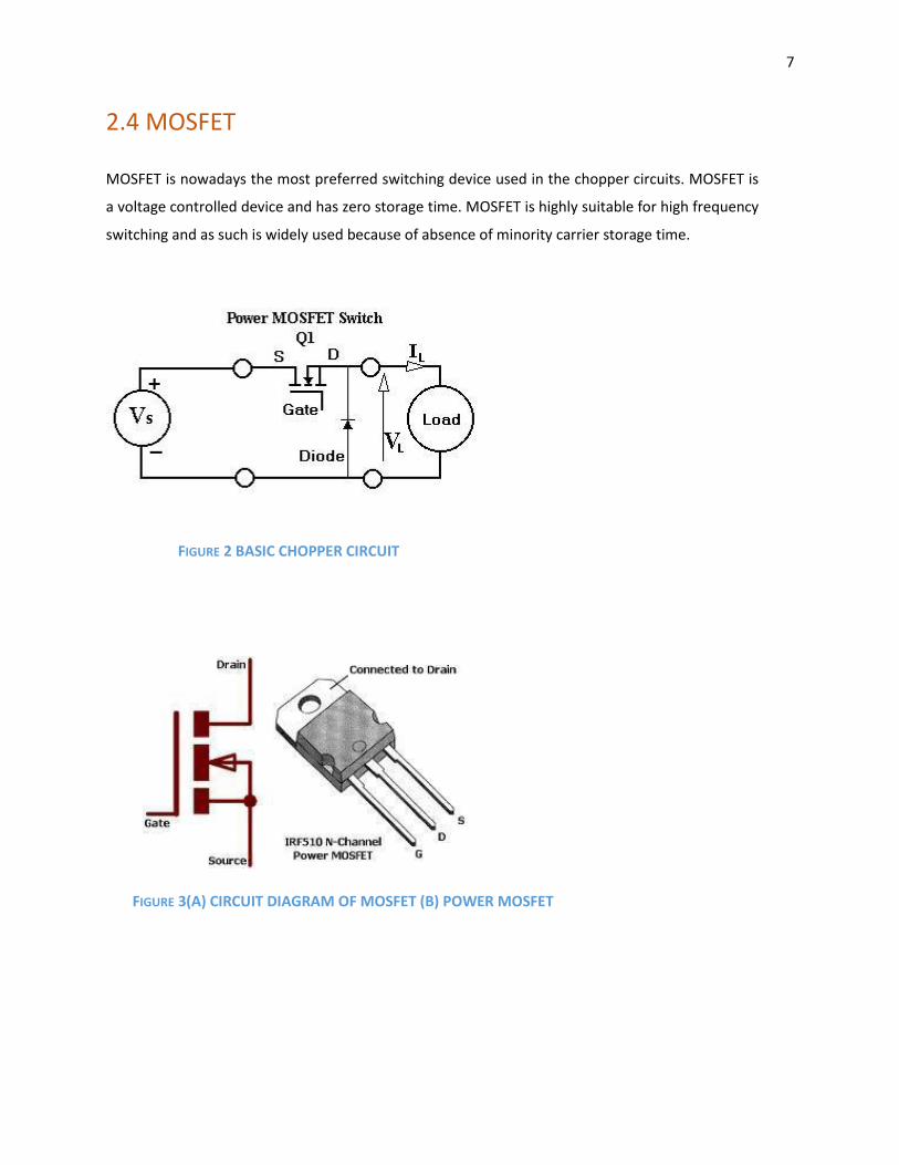
2.4 MOSFET MOSFET is nowadays the most preferred switching device used in the chopper circuits. MOSFET is
a voltage controlled device and has zero storage time. MOSFET is highly suitable for high frequency
switching and as such is widely used because of absence of minority carrier storage time.
FIGURE 2 BASIC CHOPPER CIRCUIT
FIGURE 3(A) CIRCUIT DIAGRAM OF MOSFET (B) POWER MOSFET

8
CHAPTER 3 SEPARATELY EXCITED DC MOTOR
3.1 INTRODUCTION
FIGURE 4 SEPARATELY EXCITED DC MOTOR In a separately excited dc motor the armature winding and the field winding is supplied from two
different sources. The current flows in the field winding and produces the flux which in turn interacts
with the armature current and results in the formation of the torque.
3.2 EQUATIONS INVOLVED
Field current:
VF = RFIF + LF Where RF and LF are the field resistance and inductance respectively. Armature current: = + Where RA and LA are armature resistance and inductance respectively.
Back EMF:
EG = KVWIF
Where KV is the armature voltage constant and W is the speed of rotation.
Torque developed in the machine is expressed as:
TD = KTIFIA
(3.1)
(3.2) (3.3)
(3.4)
9 Where KT is the torque constant which is assumed to be equal to be KV
Sometimes we also express the torque developed as
TD = KTIAØ (3.5)
Where Ø is the flux produced.
The developed torque is also expressed as the sum of load torque, inertia and component of friction.
TD = TL + J
+BW (3.6)
Where J= inertia of motor
B= Vicious friction constant
TL= Load torque
The motor speed is expressed as:
W = (VA – IARA)/IFRF (3.7)
The required power PD:
PD=TDW (3.8)
3.3 SPEED CONTROL:
We can control the motor speed by using the following two methods:
Armature voltage control
Field flux control
When the first method is used the field is kept constant and when the second method is used the
voltage is kept constant. First method is used for values below rated speed and the second is used
for values above rated speed.

10
3.4 RATED SPEED AND FIELD WEAKENING:
FIGURE 5 REGION OFCONSTANT TORQUE AND POWER RATED SPEED- The speed which corresponds to the rated values of armature voltage, armature
current and field current.
CONSTANT TORQUE REGION- the region below rated speed is the constant torque region and in this
region we achieve speed control by varying the armature voltage. In this region the torque is
constant while the power rises linearly with speed.
CONSTANT POWER REGION- the region above the rated speed is the constant power region. In this
region the speed is varied by varying the field flux. Here the torque gradually decreases but the power
remains constant. By decreasing the field flux we are gradually increasing the speed hence this is
known as Field Weakening.
11
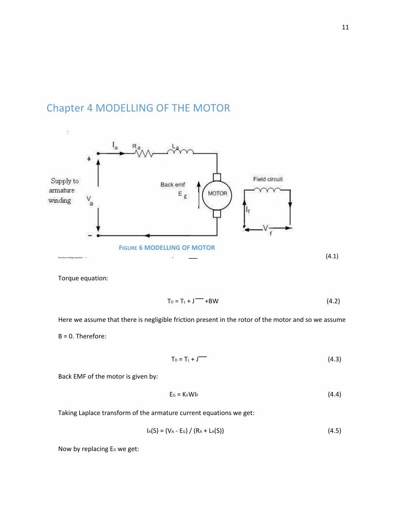
Chapter 4 MODELLING OF THE MOTOR
FIGURE 6 MODELLING OF MOTOR Armature voltage equation = + (4.1)
Torque equation:
TD = TL + J
+BW (4.2)
Here we assume that there is negligible friction present in the rotor of the motor and so we assume
B = 0. Therefore:
TD = TL + J
(4.3)
Back EMF of the motor is given by:
EG = KVWIF (4.4)
Taking Laplace transform of the armature current equations we get:
IA(S) = (VA - EG) / (RA + LA(S)) (4.5)
Now by replacing EG we get:

12
IA(S) = (VA - KVWIF) / (RA + LA (S)) (4.6)
But EG=KVØW also, so:
IA(S) = (VA - KVØW) / (RA + LA (S)) (4.7)
IA(S) = (VA - KVØW) / RA (1 + LA (S)/ RA) (4.8)
And W(S) = (TD – TL)/JS = (KTIAØ - TL)/JS (4.9)
Here we get the armature time constant as TA = LA/RA
FIGURE 7 BLOCK DIAGRAM OF SEPARATELY EXCITED DC MOTOR
Upon simplification we get the overall transfer function of the above system as:
W(S)/VA(S) = [KØ/RA]/JS (1+ TAS)/ [1+ K2Ø2/RA)/JS (1+TAS)] (4.10)
Further simplification yields:
W(S) /VA(S) = (1 /KØ) / {1 + (K²Ø² /RA) /JS (1+TAS)} (4.11)
Introducing electromechanical time constant TM as JRA / (KØ) 2
We get
W(S)/VA(S) = (1/KØ) / [STM (1+STA) + 1] (4.12)
Assuming that at the point of starting the load torque is zero and armature inductance is negligible
VA = K × Ø × W (T) + IARA (4.13)
Now the torque equation becomes:

13
TD = J
= KØIA (4.14)
Replacing the value of IA in the above equation:
VA= K × Ø × W (T) + (J
) RA/KØ (4.15)
Dividing both sides of the above equation with KØ, we get:
VA/KØ=W (T) +RA J
/ (KØ) ² (4.16)
VA/KØ equals the motor speed at no load.
Therefore, W (no load) =W (T) + RA J
/ (KØ) ² = W (T) + TM
(4.17)
Where, KØ = KM (Assume)
And TM=JRA / (KØ) ²=JRA/ (KM) ²
Therefore, J = TM (KM) ²/ RA (4.18)
From above and motor torque equation we get:
W(S) = [(RA / KM) IA(S) - TL RA / (KM) ²] (1/TM(S)) (4.19)
The largest time constant plays the most crucial part in delaying of the system when the
transfer function is in time constant form. To recompense for the delay caused in the
system we employ PI controller as speed controller. This is because the zero of the PI
controller is chosen in such a manner that this huge delay gets cancelled [1].

14
FIGURE 8 SPEED CONTROL LAYOUT

15
CHAPTER 5 PROBLEM STATEMENT[5]
Nameplate ratings of the dc motor used in the simulations are 320 kW, 440 v (dc) and 55 rad/sec.
Values of the parameters associated with the machine are:
Moment of Inertia, J = 85 Kg-m2
.
Back EMF Constant = 9 Volt-sec/rad.
Rated Current = 715 A. Maximum Current Limit = 1000 A. Resistance of Armature, RA = 0.025 ohm.
Armature Inductance, LA = 0.72 mH.
Speed Feedback Filter Time Constant, T1 = 25 ms.
Current Filter Time Constant, T2 = 3.5 ms.
5.1 PARAMETERS FOR CURRENT CONTROL:
Current PI type controller is given by:
KC (1 + TCS)/TCS here, TC = TA and Kc = RATA / (2K2KTT2)
TA = LA/RA = 0.72*10-3/0.025 = 29.9 ms.
For the analog circuit maximum value of controller output is ± 10 Volts.
Therefore, KT = 440/10 = 44. Also, K2 = 10/1000 = 1/100. Now, putting value of RA, TA, K2, KT and T2 we get: KC = 0.24.

16
5.2 Parameters for speed control:
Speed PI type controller is expressed as: KN {(1+TNS)/TNS} Here, TN = 4ms.
And, K = TMKMK2/ (2K1RA
Tm = JRA/Km = 85*0.025/9 = 22.9 ms.
Now, KN = (22.9*9*1)/ (2*0.18*0.025*32*100) = 6.20
17
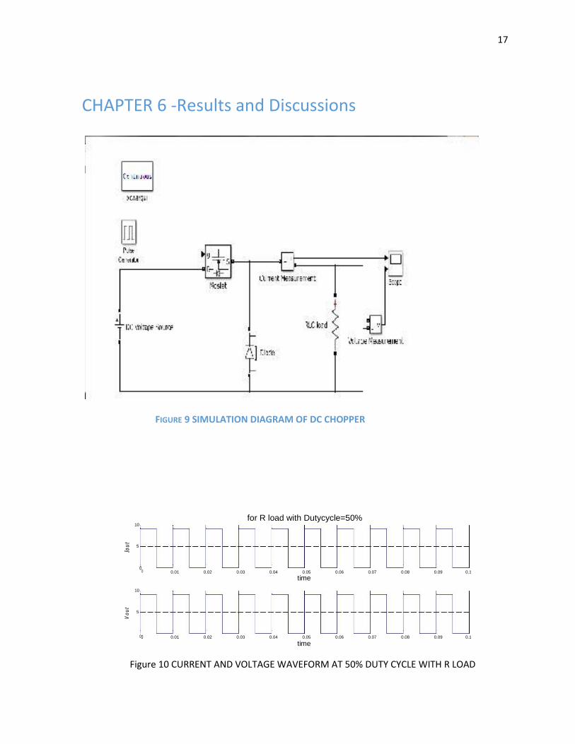
CHAPTER 6 -Results and Discussions
FIGURE 9 SIMULATION DIAGRAM OF DC CHOPPER
Iou
t
Vo
ut
for R load with Dutycycle=50% 10
5
0
0 0.01 0.02 0.03 0.04 0.05 0.06 0.07 0.08 0.09 0.1 time
10
5
00 0.01 0.02 0.03 0.04 0.05 0.06 0.07 0.08 0.09 0.1
time Figure 10 CURRENT AND VOLTAGE WAVEFORM AT 50% DUTY CYCLE WITH R LOAD
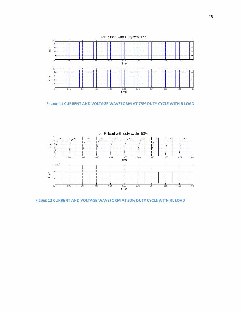
18
Iou
t
vo
ut
for R load with Dutycycle=75
10
8
6
4
2
0
0 0.01 0.02 0.03 0.04 0.05 0.06 0.07 0.08 0.09 0.1
time
10
8
6
4
2
0
0 0.01 0.02 0.03 0.04 0.05 0.06 0.07 0.08 0.09 0.1
time
FIGURE 11 CURRENT AND VOLTAGE WAVEFORM AT 75% DUTY CYCLE WITH R LOAD
for Rl load with duty cycle=50% 10
8
Iou
t 6
4
2
0 0 0.01 0.02 0.03 0.04 0.05 0.06 0.07 0.08 0.09 0.1
time
5 x 10⁵
Vout
0 -5 -10
0 0.01 0.02 0.03 0.04 0.05 0.06 0.07 0.08 0.09 0.1
time
FIGURE 12 CURRENT AND VOLTAGE WAVEFORM AT 50% DUTY CYCLE WITH RL LOAD

19
iou
t
vo
ut
for RL load with Duty cycle=50% with free wheeling diode 10
5
0
-5 0 0.01 0.02 0.03 0.04 0.05 0.06 0.07 0.08 0.09 0.1
time
10
5
0
-5 0 0.01 0.02 0.03 0.04 0.05 0.06 0.07 0.08 0.09 0.1
time
FIGURE 13 CURRENT AND VOLTAGE WAVEFORM AT 50% DUTY CYCLE WITH RL LOAD AND FREEWHEELING DIODE
2 x 10 -5 for RLC load with free wheeling diode at 50% duty cycle
1
iou
t
0
-1
-20 0.01 0.02 0.03 0.04 0.05 0.06 0.07 0.08 0.09 0.1
time
10.002
10
vou
t
9.998
9.996
9.994 0 0.01 0.02 0.03 0.04 0.05 0.06 0.07 0.08 0.09 0.1
time
FIGURE 14 CURRENT AND VOLTAGE WAVEFORM AT 50% DUTY CYCLE WITH RLC LOAD AND FREEWHEELING DIODE

20
4 x 10 -3 for RLE load with freewheeling diode at 50%duty cycle
2
iou
t
0
-2
-4
0.01 0.0105 0.011 0.0115 0.012 0.0125 0.013 0.0135 0.014 0.0145 0.015
time
10.05
10
vo
ut
9.95
9.9
0.01 0.0105 0.011 0.0115 0.012 0.0125 0.013 0.0135 0.014 0.0145 0.015
time
FIGURE 15 CURRENT AND VOLTAGE WAVEFORM AT 50% DUTY CYCLE WITH RLE LOAD AND
FREEWHEELING DIODE FIGURE 16 SIMULINK MODEL FOR SPEED CONTROL WITHOUT FILTER

21
FIGURE 17 SIMULINK MODEL FOR SPEED CONTROL WITH FILTER FIGURE 18 SPEED RESPONSE WHEN REF SPEED EQUAL TO RATED SPEED AT FULL LOAD
WITHOUT FILTER

22 FIGURE 19 ERROR IN SPEED RESPONSE WHEN REF SPEED EQUAL TO RATED SPEED AT FULL LOAD
WITHOUT FILTER
FIGURE 20 SPEED RESPONSE WHEN REF SPEED EQUAL TO RATED SPEED AT FULL
LOAD WITH FILTER
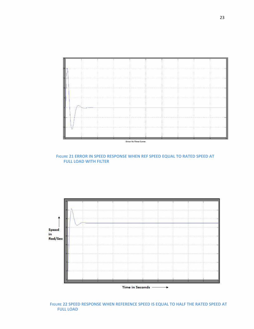
23
FIGURE 21 ERROR IN SPEED RESPONSE WHEN REF SPEED EQUAL TO RATED SPEED AT FULL LOAD WITH FILTER
FIGURE 22 SPEED RESPONSE WHEN REFERENCE SPEED IS EQUAL TO HALF THE RATED SPEED AT FULL LOAD

24
FIGURE 23 ERROR IN SPEED RESPONSE WHEN REFERENCE SPEED IS EQUAL TO HALF THE RATED SPEED AT FULL LOAD
FIGURE 24 SPEED RESPONSE WHEN REFERENCE SPEED IS EQUAL TO THE RATED SPEED AT HALF OF
FULL LOAD

25
FIGURE 25 ERROR IN SPEED RESPONSE WHEN REFERENCE SPEED IS EQUAL TO THE RATED
SPEED AT HALF OF FULL LOAD
FIGURE 26 SPEED RESPONSE WHEN REFERENCE SPEED IS EQUAL TO HALF THE RATED SPEED AT HALF LOAD

26
FIGURE 27 ERROR IN SPEED RESPONSE WHEN REFERENCE SPEED IS EQUAL TO HALF THE RATED
SPEED AT HALF LOAD
FIGURE 28 SPEED RESPONSE WHEN REFERENCE SPEED IS EQUAL TO THE RATED SPEED WHEN
APPLIED TO STEP LOAD TORQUE
27
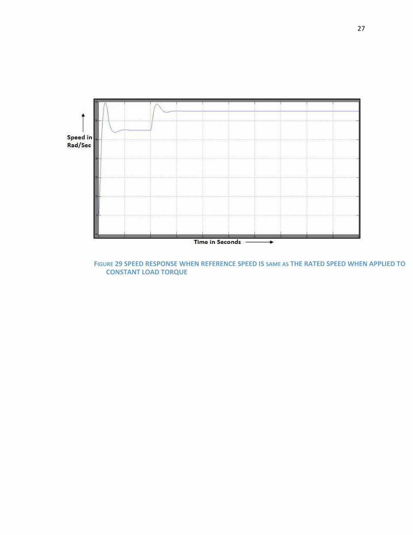
FIGURE 29 SPEED RESPONSE WHEN REFERENCE SPEED IS SAME AS THE RATED SPEED WHEN APPLIED TO
CONSTANT LOAD TORQUE

28
6.2 Conclusion
Here we see that the speed of a dc motor can be successfully controlled by employing a chopper
circuit. Here we initially study the basic output characteristics of a MOSFET based chopper and study
the output variables for various load characteristics and then we move on towards the simulation of
the closed loop model of the dc system involving the chopper and then study it for various change in
load torque, rated voltage value and other input parameters. The loops involved are carefully
optimized using various mathematical approaches and finally the circuit is simulated and the various
plots obtained under various conditions are carefully studied.
6.3 FUTURE SCOPE:
The above described model has been run and tested successfully in MATLAB simulation, so there
lies the opportunity to implement the above described model in hardware and study the impact
of the approach taken in this thesis report. Moreover in this report we have analyzed only the
impact of the approach on separately excited dc motor so there lies the scope to extend the
study to various other kinds of motors. Also here we have done the speed control below the
rated speed so analysis can also be extended to study the dynamics for above the rated speed
using field flux control.

29
CHAPTER 7-References and bibliography [1] Gopakumar, K., Power Electronics and Electrical Drives, Video Lectures 1-25, Centre for Electronics and Technology, Indian Institute of Science, Bangalore. [2] Bimbhra, P.S., Power Electronics. New Delhi, Khanna Publishers, 2006. [3] Gopal, M., Control Systems, Principles and Design. New Delhi, Tata McGraw Hill Publishing Company limited, 2008. [4] MATLAB SIMULINK, version 2009, SimPowerSystem, One quadrant chopper DC drive. [5] Speed Control of DC Motor using Modulus Hugging Approach Sarat Kumar Sahoo*, Razia Sultana†, Megha Rout
[6] Journal of Kerbala University , Vol. 11 No.1 Scientific . 2013 26 Speed control of separately excited DC
motor using chopper Jaafer Sadiq Jaafer Electric Dept/ Kufa Institute/ Foundation of Technical Education
Mohammed Chessab Mahdi Computer Center/ Kufa Institute / Foundation of Technical Education
[7] Verification of Modulus Hugging Approach for Controlled Rectifier Fed SEDC Motor Using Bode
Plot 1Raju Singh* and 2 A.K. Pandey