Embed Size (px)
Citation preview
Design-guideline for spotwelding of steel sheet metals Page 1 of 10; 15.05.2005
1 General Items
1.1 Force of Electrodes
• The values for the electrode forces as shown in the table (page 3 to 5) are standard values (as also the values for welding time and current), which correspond to prior art. These standard values can be adjusted for the actual connection. For this it has to be considered, that a change of the electrode forces also requires a change of the welding current and perhaps of the welding time. Besides the welding range is reduced with low electrode forces and the possibility of sparks will grow. This can be compensated with longer welding times.
• The values for the electrode forces shown in the table (page 3 to 5) are valid for standard sheet metals with good fitting
• For bad fitting, the electrode force has to be increased depending on the sheet metal thickness, the material and the fitting (up to 10%)
• For zinc-coated sheet metal with or without additional organic coating, the mentioned electrode force has to be increased by approx. 10%
• For high-strength ZStE-sheets, the electrode force has to be increased as following: ZStE 260: 10%; ZStE 340: 15%; ZStE 420: 20%
• Different welding connections (different sheet metal combinations) are welded with one electrode force, if the electrode forces of the single weldings show a difference up to 30%. If the difference is higher, the weldings have to be done with two electrode forces. Example: Sheet metal combination 1: t1 = 1.25 mm, ZStE 340 t2 = 1.25 mm electrode force 3300 N (see table) 500 N (15 % for ZStE 340) ---------- 3800 N Sheet metal combination 2: t1 = 1.50 mm, zinc-coated, ZStE 340 t2 = 2.00 mm, zinc-coated, ZStE 260 electrode force 3900 N (see table)
390 N (10 % for zinc-coated) 585 N (15 % for ZStE 340)
---------- 4875 N 3800 N + 30% = 4940 N > 4875 N à one electrode force: 4875 N
• For special requirements for electrode depressions and/or gaps, the mentioned allowance of up to 30% has to be reduced accordingly.
• The advance time (pressure time) has to be chosen (if necessary with measuring instruments), so that with the start of the flow of the welding current the required electrode force is available.
1.2 For the dimensioning of the of the force generation systems it has to be taken care, that the required electrode force is reached at approx. 75 bar (HFA)
Design-guideline for spotwelding of steel sheet metals Page 2 of 10; 15.05.2005
respectively 4.5 bar (pneumatics), to make sure that the electrode force can be increased in case of bad fitting.
1.3 The dimensioning of the welding elements has to be done for the maximum possible forces (100 bar for HFA, 5 bar for pneumatics)
1.4 The pneumatic welding cylinders in the welding equipment are generally adjusted to 5 bar, that is that the welding is done with 10% more electrode force compared to table values. The other welding parameters have to be adjusted accordingly. If a lower electrode force is required, a pressure reduction valve has to be installed.
1.5 For the dimensioning of the welding transformers, a sufficient reserve for the stepper function has to be considered.(I nominal + 4 kA).
1.6 For organic coated sheet metals tip dressers have to be provided, if one or both electrodes touch the coating.
1.7 Copper plates, that touch a coating, have to be avoided
1.8 Visible spots on organic coatings have to be avoided.
1.9 Sufficient cooling of the electrodes (min. 2 l/min per electrode) and the transformers (manufacturer data) has to be guaranteed. The flow amount is more important than the temperature. Which should be max. 30°C.
1.10 With adhesive or sealer in one or two joining plains, usually the advance and/or welding time has to be increased according to the actual situation.
1.11 Isolation • For multi spotweld facilities the copper plates have to be isolated, if necessary
also against each other • The isolation should be as close to the welding position as possible. • Locators, guides and holding-down-devices must not be on the same potential
as copper plates and electrodes.
Design-guideline for spotwelding of steel sheet metals Page 3 of 10; 15.05.2005
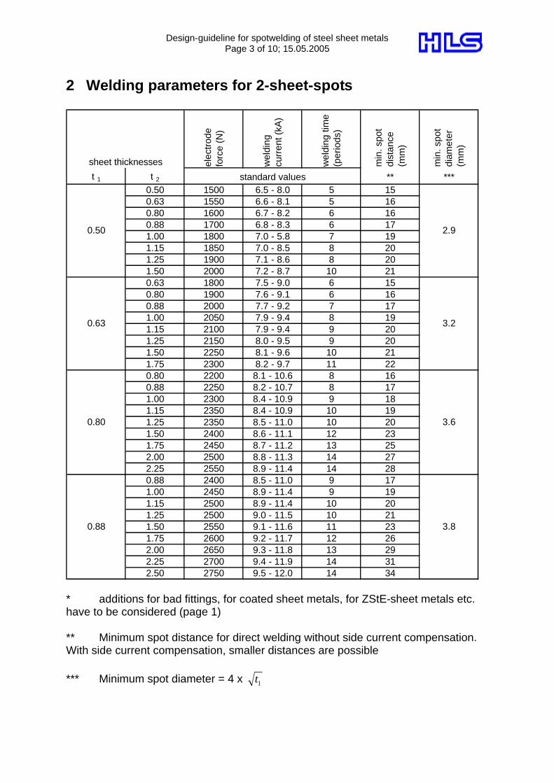
2 Welding parameters for 2-sheet-spots
elec
trod
e fo
rce
(N)
wel
ding
cu
rren
t (kA
)
wel
ding
tim
e (p
erio
ds)
min
. spo
t di
stan
ce
(mm
)
min
. spo
t di
amet
er
(mm
)
t 1 t 2 ** ***0.50 1500 6.5 - 8.0 5 150.63 1550 6.6 - 8.1 5 160.80 1600 6.7 - 8.2 6 160.88 1700 6.8 - 8.3 6 171.00 1800 7.0 - 5.8 7 191.15 1850 7.0 - 8.5 8 201.25 1900 7.1 - 8.6 8 201.50 2000 7.2 - 8.7 10 210.63 1800 7.5 - 9.0 6 150.80 1900 7.6 - 9.1 6 160.88 2000 7.7 - 9.2 7 171.00 2050 7.9 - 9.4 8 191.15 2100 7.9 - 9.4 9 201.25 2150 8.0 - 9.5 9 201.50 2250 8.1 - 9.6 10 211.75 2300 8.2 - 9.7 11 220.80 2200 8.1 - 10.6 8 160.88 2250 8.2 - 10.7 8 171.00 2300 8.4 - 10.9 9 181.15 2350 8.4 - 10.9 10 191.25 2350 8.5 - 11.0 10 201.50 2400 8.6 - 11.1 12 231.75 2450 8.7 - 11.2 13 252.00 2500 8.8 - 11.3 14 272.25 2550 8.9 - 11.4 14 280.88 2400 8.5 - 11.0 9 171.00 2450 8.9 - 11.4 9 191.15 2500 8.9 - 11.4 10 201.25 2500 9.0 - 11.5 10 211.50 2550 9.1 - 11.6 11 231.75 2600 9.2 - 11.7 12 262.00 2650 9.3 - 11.8 13 292.25 2700 9.4 - 11.9 14 312.50 2750 9.5 - 12.0 14 34
0.88
3.6
3.8
2.9
0.63 3.2
0.80
sheet thicknesses
standard values
0.50
* additions for bad fittings, for coated sheet metals, for ZStE-sheet metals etc. have to be considered (page 1) ** Minimum spot distance for direct welding without side current compensation. With side current compensation, smaller distances are possible *** Minimum spot diameter = 4 x 1t
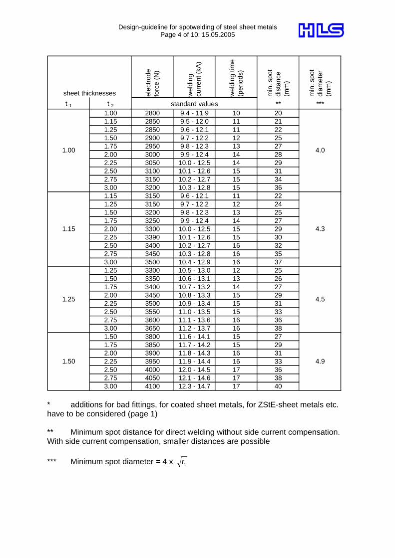
Design-guideline for spotwelding of steel sheet metals Page 4 of 10; 15.05.2005
elec
trod
e fo
rce
(N)
wel
ding
cu
rren
t (kA
)
wel
ding
tim
e (p
erio
ds)
min
. spo
t di
stan
ce
(mm
)
min
. spo
t di
amet
er
(mm
)
t 1 t 2 ** ***1.00 2800 9.4 - 11.9 10 201.15 2850 9.5 - 12.0 11 211.25 2850 9.6 - 12.1 11 221.50 2900 9.7 - 12.2 12 251.75 2950 9.8 - 12.3 13 272.00 3000 9.9 - 12.4 14 282.25 3050 10.0 - 12.5 14 292.50 3100 10.1 - 12.6 15 312.75 3150 10.2 - 12.7 15 343.00 3200 10.3 - 12.8 15 361.15 3150 9.6 - 12.1 11 221.25 3150 9.7 - 12.2 12 241.50 3200 9.8 - 12.3 13 251.75 3250 9.9 - 12.4 14 272.00 3300 10.0 - 12.5 15 292.25 3390 10.1 - 12.6 15 302.50 3400 10.2 - 12.7 16 322.75 3450 10.3 - 12.8 16 353.00 3500 10.4 - 12.9 16 371.25 3300 10.5 - 13.0 12 251.50 3350 10.6 - 13.1 13 261.75 3400 10.7 - 13.2 14 272.00 3450 10.8 - 13.3 15 292.25 3500 10.9 - 13.4 15 312.50 3550 11.0 - 13.5 15 332.75 3600 11.1 - 13.6 16 363.00 3650 11.2 - 13.7 16 381.50 3800 11.6 - 14.1 15 271.75 3850 11.7 - 14.2 15 292.00 3900 11.8 - 14.3 16 312.25 3950 11.9 - 14.4 16 332.50 4000 12.0 - 14.5 17 362.75 4050 12.1 - 14.6 17 383.00 4100 12.3 - 14.7 17 40
sheet thicknesses
standard values
1.00
1.50
4.5
4.9
4.0
1.15 4.3
1.25
* additions for bad fittings, for coated sheet metals, for ZStE-sheet metals etc. have to be considered (page 1) ** Minimum spot distance for direct welding without side current compensation. With side current compensation, smaller distances are possible *** Minimum spot diameter = 4 x 1t
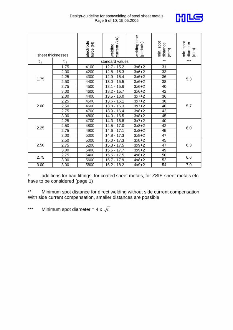
Design-guideline for spotwelding of steel sheet metals Page 5 of 10; 15.05.2005
elec
trod
e fo
rce
(N)
wel
ding
cu
rren
t (kA
)
wel
ding
tim
e (p
erio
ds)
min
. spo
t di
stan
ce
(mm
)
min
. spo
t di
amet
er
(mm
)
t 1 t 2 ** ***1.75 4100 12.7 - 15.2 3x6+2 312.00 4200 12.8 - 15.3 3x6+2 332.25 4300 12.9 - 15.4 3x6+2 362.50 4400 13.0 - 15.5 3x6+2 382.75 4500 13.1 - 15.6 3x6+2 403.00 4600 13.2 - 15.7 3x6+2 422.00 4400 13.5 - 16.0 3x7+2 362.25 4500 13.6 - 16.1 3x7+2 382.50 4600 13.8 - 16.3 3x7+2 402.75 4700 13.9 - 16.4 3x8+2 423.00 4800 14.0 - 16.5 3x8+2 452.25 4700 14.3 - 16.8 3x7+2 402.50 4800 14.5 - 17.0 3x8+2 422.75 4900 14.6 - 17.1 3x8+2 453.00 5000 14.8 - 17.3 3x8+2 472.50 5000 15.0 - 17.3 3x8+2 452.75 5200 15.3 - 17.5 3x9+2 473.00 5400 15.5 - 17.7 3x9+2 492.75 5400 15.5 - 17.5 4x8+2 503.00 5600 15.7 - 17.9 4x8+2 52
3.00 3.00 5800 16.2 - 18.2 4x9+2 54 7.0
2.75 6.6
6.0
6.3
5.3
2.00 5.7
2.25
sheet thicknesses
standard values
1.75
2.50
* additions for bad fittings, for coated sheet metals, for ZStE-sheet metals etc. have to be considered (page 1) ** Minimum spot distance for direct welding without side current compensation. With side current compensation, smaller distances are possible *** Minimum spot diameter = 4 x 1t
Design-guideline for spotwelding of steel sheet metals Page 6 of 10; 15.05.2005
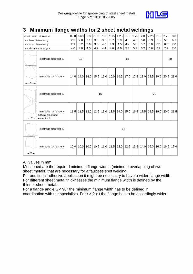
3 Minimum flange widths for 2 sheet metal weldings sheet metal thickness t 0.50 0.63 0.8 0.88 1.0 1.15 1.25 1.5 1.75 2.0 2.25 2.5 2.75 3.0min. lens diameter dL 2.5 2.8 3.1 3.3 3.5 3.7 3.9 4.3 4.6 5.0 5.3 5.5 5.8 6.1min. spot diameter dP 2.9 3.2 3.6 3.8 4.0 4.3 4.5 4.9 5.3 5.7 6.0 6.3 6.6 7.0min. distance to edge v 4.0 4.0 4.0 4.2 4.4 4.6 4.9 5.3 5.7 6.2 6.6 6.9 7.2 7.6
electrode diameter dE
min. width of flange w 14.0 14.0 14.0 15.5 16.0 16.0 16.5 17.0 17.5 18.0 18.5 19.0 20.5 21.0
electrode diameter dE
min. width of flange w 11.5 11.5 12.0 12.5 13.0 13.5 14.0 15.0 16.5 17.5 18.5 19.0 20.0 21.5
electrode diameter dE
min. width of flange w 10.0 10.0 10.0 10.5 11.0 11.5 12.0 12.5 13.5 14.0 15.0 16.0 16.5 17.0
16
13 16 20
16 20
special electrodeexception!
All values in mm Mentioned are the required minimum flange widths (minimum overlapping of two sheet metals) that are necessary for a faultless spot welding. For additional adhesive application it might be necessary to have a wider flange width For different sheet metal thicknesses the minimum flange width is defined by the thinner sheet metal. For a flange angle α < 90° the minimum flange width has to be defined in coordination with the specialists. For r > 2 x t the flange has to be accordingly wider.
w
w
w
Design-guideline for spotwelding of steel sheet metals Page 7 of 10; 15.05.2005
w
dE
theo
v
α
r
wtheo
v
v
α
wtheo
r
d
v
E
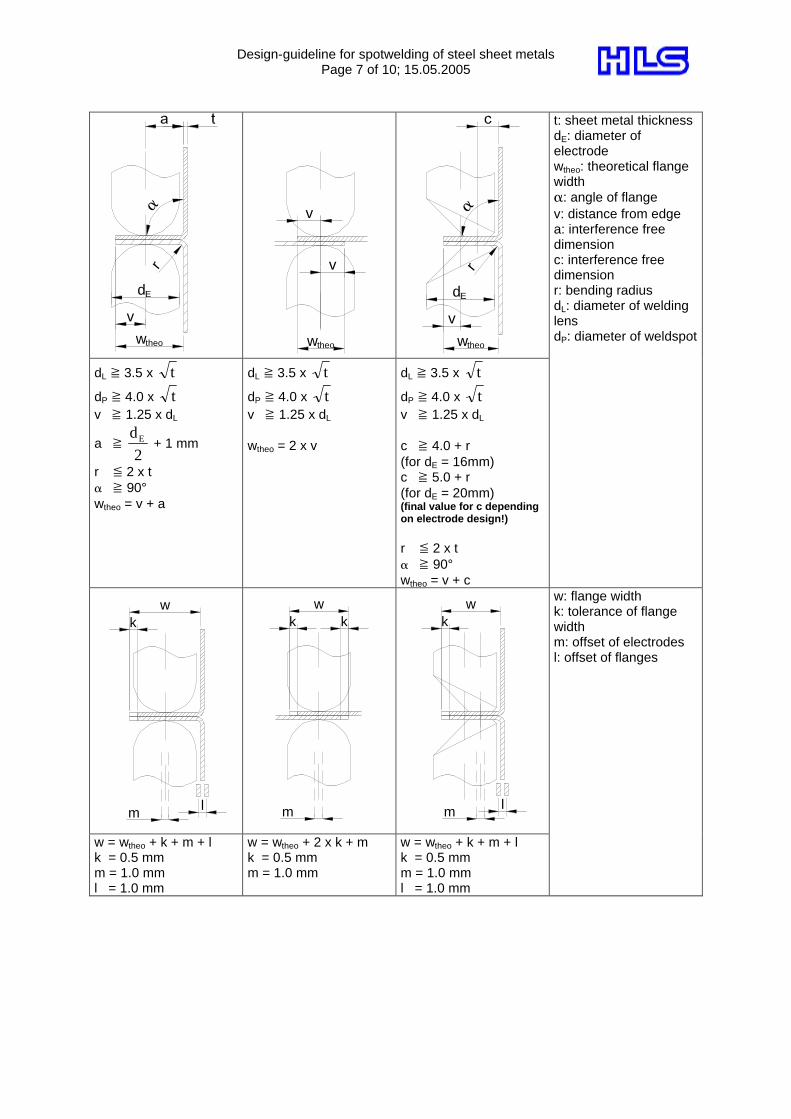
t: sheet metal thickness dE: diameter of electrode wtheo: theoretical flange width α: angle of flange v: distance from edge a: interference free dimension c: interference free dimension r: bending radius dL: diameter of welding lens dP: diameter of weldspot
dL ] 3.5 x t
dP ] 4.0 x t v ] 1.25 x dL
a ] 2
dE + 1 mm
r * 2 x t α ] 90° wtheo = v + a
dL ] 3.5 x t
dP ] 4.0 x t v ] 1.25 x dL wtheo = 2 x v
dL ] 3.5 x t
dP ] 4.0 x t v ] 1.25 x dL c ] 4.0 + r (for dE = 16mm) c ] 5.0 + r (for dE = 20mm) (final value for c depending on electrode design!) r * 2 x t α ] 90° wtheo = v + c
wk
m l
wk k
m
wk
m l
w: flange width k: tolerance of flange width m: offset of electrodes l: offset of flanges
w = wtheo + k + m + l k = 0.5 mm m = 1.0 mm l = 1.0 mm
w = wtheo + 2 x k + m k = 0.5 mm m = 1.0 mm
w = wtheo + k + m + l k = 0.5 mm m = 1.0 mm l = 1.0 mm
Design-guideline for spotwelding of steel sheet metals Page 8 of 10; 15.05.2005
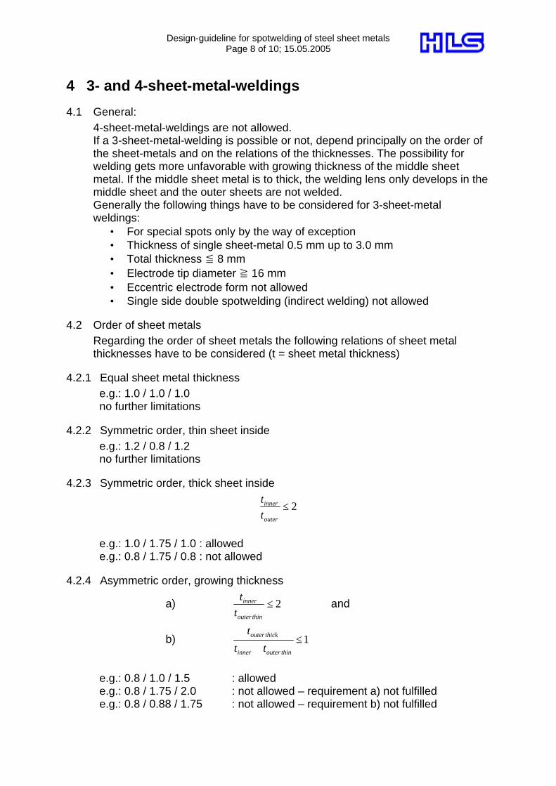
4 3- and 4-sheet-metal-weldings
4.1 General: 4-sheet-metal-weldings are not allowed. If a 3-sheet-metal-welding is possible or not, depend principally on the order of the sheet-metals and on the relations of the thicknesses. The possibility for welding gets more unfavorable with growing thickness of the middle sheet metal. If the middle sheet metal is to thick, the welding lens only develops in the middle sheet and the outer sheets are not welded. Generally the following things have to be considered for 3-sheet-metal weldings:
• For special spots only by the way of exception • Thickness of single sheet-metal 0.5 mm up to 3.0 mm • Total thickness * 8 mm • Electrode tip diameter ] 16 mm • Eccentric electrode form not allowed • Single side double spotwelding (indirect welding) not allowed
4.2 Order of sheet metals Regarding the order of sheet metals the following relations of sheet metal thicknesses have to be considered (t = sheet metal thickness)
4.2.1 Equal sheet metal thickness e.g.: 1.0 / 1.0 / 1.0 no further limitations
4.2.2 Symmetric order, thin sheet inside e.g.: 1.2 / 0.8 / 1.2 no further limitations
4.2.3 Symmetric order, thick sheet inside
2≤outer
inner
tt
e.g.: 1.0 / 1.75 / 1.0 : allowed e.g.: 0.8 / 1.75 / 0.8 : not allowed
4.2.4 Asymmetric order, growing thickness
a) 2≤thinouter
inner
tt
and
b) 1≤+ thinouterinner
thickouter
tt
t
e.g.: 0.8 / 1.0 / 1.5 : allowed e.g.: 0.8 / 1.75 / 2.0 : not allowed – requirement a) not fulfilled e.g.: 0.8 / 0.88 / 1.75 : not allowed – requirement b) not fulfilled
Design-guideline for spotwelding of steel sheet metals Page 9 of 10; 15.05.2005
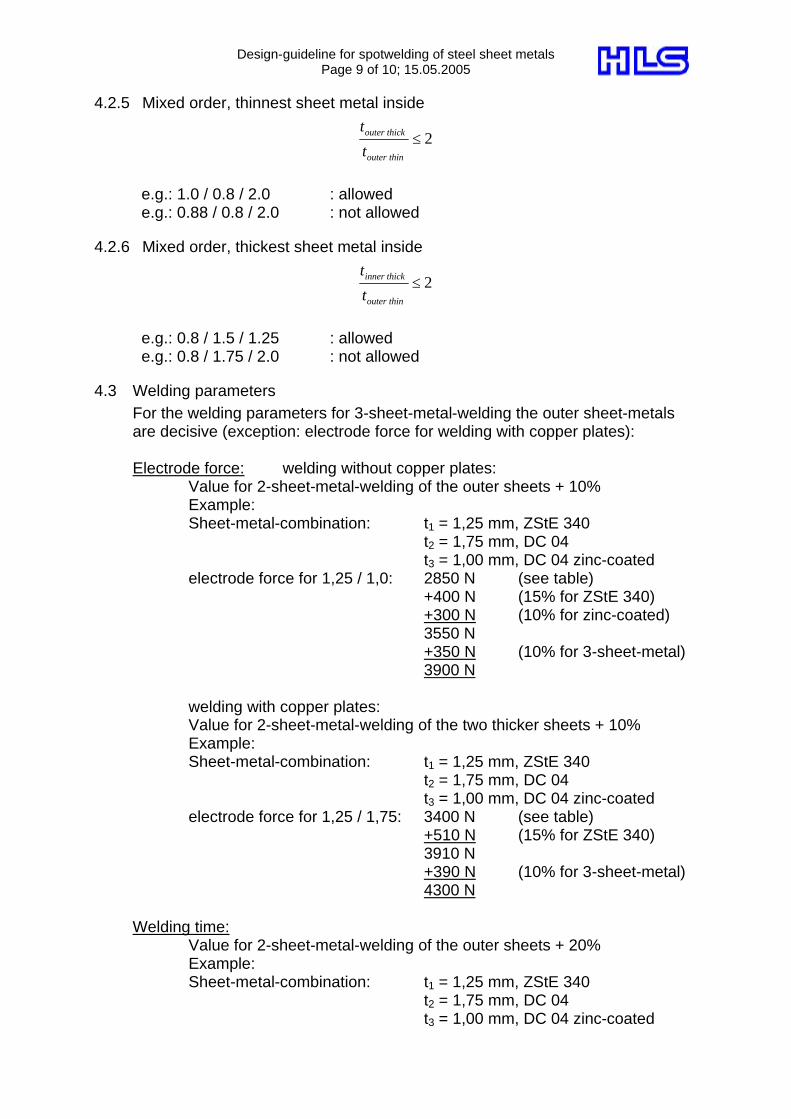
4.2.5 Mixed order, thinnest sheet metal inside
2≤thinouter
thickouter
t
t
e.g.: 1.0 / 0.8 / 2.0 : allowed e.g.: 0.88 / 0.8 / 2.0 : not allowed
4.2.6 Mixed order, thickest sheet metal inside
2≤thinouter
thickinner
t
t
e.g.: 0.8 / 1.5 / 1.25 : allowed e.g.: 0.8 / 1.75 / 2.0 : not allowed
4.3 Welding parameters For the welding parameters for 3-sheet-metal-welding the outer sheet-metals are decisive (exception: electrode force for welding with copper plates): Electrode force: welding without copper plates: Value for 2-sheet-metal-welding of the outer sheets + 10% Example: Sheet-metal-combination: t1 = 1,25 mm, ZStE 340 t2 = 1,75 mm, DC 04 t3 = 1,00 mm, DC 04 zinc-coated electrode force for 1,25 / 1,0: 2850 N (see table) +400 N (15% for ZStE 340) +300 N (10% for zinc-coated) 3550 N +350 N (10% for 3-sheet-metal) 3900 N
welding with copper plates: Value for 2-sheet-metal-welding of the two thicker sheets + 10% Example: Sheet-metal-combination: t1 = 1,25 mm, ZStE 340 t2 = 1,75 mm, DC 04 t3 = 1,00 mm, DC 04 zinc-coated electrode force for 1,25 / 1,75: 3400 N (see table) +510 N (15% for ZStE 340) 3910 N +390 N (10% for 3-sheet-metal) 4300 N Welding time: Value for 2-sheet-metal-welding of the outer sheets + 20% Example: Sheet-metal-combination: t1 = 1,25 mm, ZStE 340 t2 = 1,75 mm, DC 04 t3 = 1,00 mm, DC 04 zinc-coated
Design-guideline for spotwelding of steel sheet metals Page 10 of 10; 15.05.2005
welding time for 1,25 / 1,0: 11 Periods (see table) +2 Periods (20% for 3-sheet-metal) 13 Periods Welding current: For the welding current it is only possible to provide approximate values. The welding current has to be selected so that, with the given value for electrode force and welding time, the welding is close to the limit for sparks. Approximate value: Value for 2-sheet-metal-welding of the outer sheets + 10%
4.4 Minimum flange width For the determination of minimum flange width for 3-sheet-metal-weldings the outer panels are decisive. The values shown in the table “Minimum flange widths for 2 sheet metal weldings” (page 6) have to be increased for 3-sheet-metal-weldings by 1.5 mm due to the larger welding lens and the higher tolerances of flange widths. Example: Sheet-metal-combination: t1 = 1,25 mm t2 = 1,75 mm t3 = 1,00 mm
flange width for 1.25/1.00: 16.0 mm (see table) +1.5 mm (due to 3-sheet-metal) 17.5 mm