Embed Size (px)
Citation preview
Spring-applied brakeINTORQ BFK458
The versatile modular system 1.5 – 600 Nm
setting the standard
www.intorq.de
�
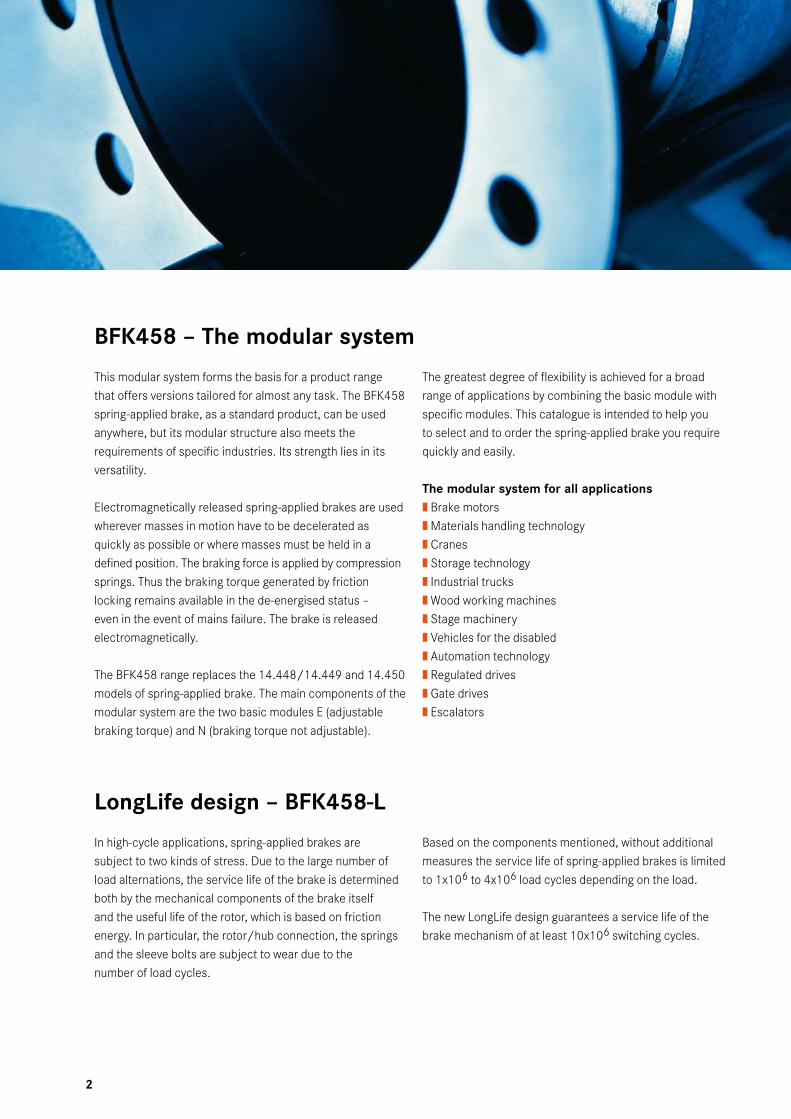
BFK458 – The modular system
This modular system forms the basis for a product range that offers versions tailored for almost any task. The BFK458 spring-applied brake, as a standard product, can be used anywhere, but its modular structure also meets the requirements of specific industries. Its strength lies in its versatility.
Electromagnetically released spring-applied brakes are used wherever masses in motion have to be decelerated as quickly as possible or where masses must be held in a defined position. The braking force is applied by compression springs. Thus the braking torque generated by friction locking remains available in the de-energised status – even in the event of mains failure. The brake is released electromagnetically.
The BFK458 range replaces the 14.448/14.449 and 14.450 models of spring-applied brake. The main components of the modular system are the two basic modules E (adjustable braking torque) and N (braking torque not adjustable).
The greatest degree of flexibility is achieved for a broad range of applications by combining the basic module with specific modules. This catalogue is intended to help you to select and to order the spring-applied brake you require quickly and easily.
The modular system for all applications| Brake motors| Materials handling technology| Cranes| Storage technology| Industrial trucks| Wood working machines| Stage machinery| Vehicles for the disabled| Automation technology| Regulated drives| Gate drives| Escalators
LongLife design – BFK458-L
In high-cycle applications, spring-applied brakes are subject to two kinds of stress. Due to the large number of load alternations, the service life of the brake is determined both by the mechanical components of the brake itself and the useful life of the rotor, which is based on friction energy. In particular, the rotor/hub connection, the springs and the sleeve bolts are subject to wear due to thenumber of load cycles.
Based on the components mentioned, without additional measures the service life of spring-applied brakes is limited to 1x10⁶ to 4x10⁶ load cycles depending on the load.
The new LongLife design guarantees a service life of the brake mechanism of at least 10x106 switching cycles.
�
INTORQ I spring-applied brake INTORQ BFK458 I en 7/�010
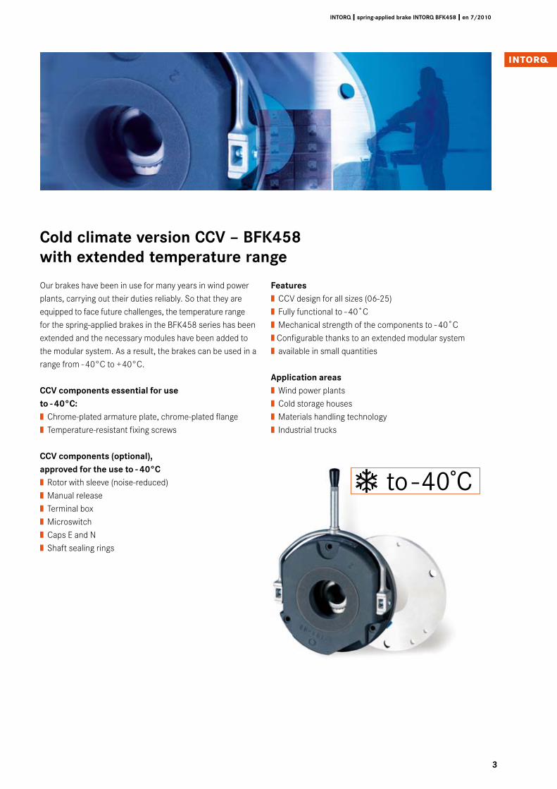
Cold climate version CCV – BFK458 with extended temperature range
Our brakes have been in use for many years in wind power plants, carrying out their duties reliably. So that they are equipped to face future challenges, the temperature range for the spring-applied brakes in the BFK458 series has been extended and the necessary modules have been added to the modular system. As a result, the brakes can be used in a range from - 40°C to +40°C.
CCV components essential for use to - 40°C:| Chrome-plated armature plate, chrome-plated flange| Temperature-resistant fixing screws
CCV components (optional),approved for the use to - 40°C| Rotor with sleeve (noise-reduced)| Manual release| Terminal box| Microswitch| Caps E and N| Shaft sealing rings
Features| CCV design for all sizes (06-25)| Fully functional to - 40˚C| Mechanical strength of the components to - 40˚C| Configurable thanks to an extended modular system| available in small quantities
Application areas| Wind power plants| Cold storage houses| Materials handling technology| Industrial trucks
to -40̊ C
4
INTORQ I spring-applied brake INTORQ BFK458 I en 7/2010
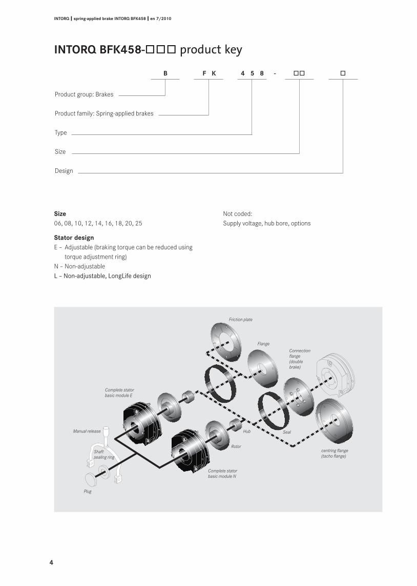
INTORQ BFK458-òòò product key
Friction plate
Flange
Connectionflange(double brake)
centring flange(tacho flange)
SealHub
Rotor
Complete statorbasic module N
Plug
Shaftsealing ring
Complete statorbasic module E
Manual release
Size06, 08, 10, 12, 14, 16, 18, 20, 25
Stator designE – Adjustable (braking torque can be reduced using
torque adjustment ring) N – Non-adjustableL – Non-adjustable, LongLife design
Not coded:Supply voltage, hub bore, options
B F K 4 5 8 - òò ò
Product group: Brakes
Product family: Spring-applied brakes
Type
Size
Design
5
INTORQ I spring-applied brake INTORQ BFK458 I en 7/�010
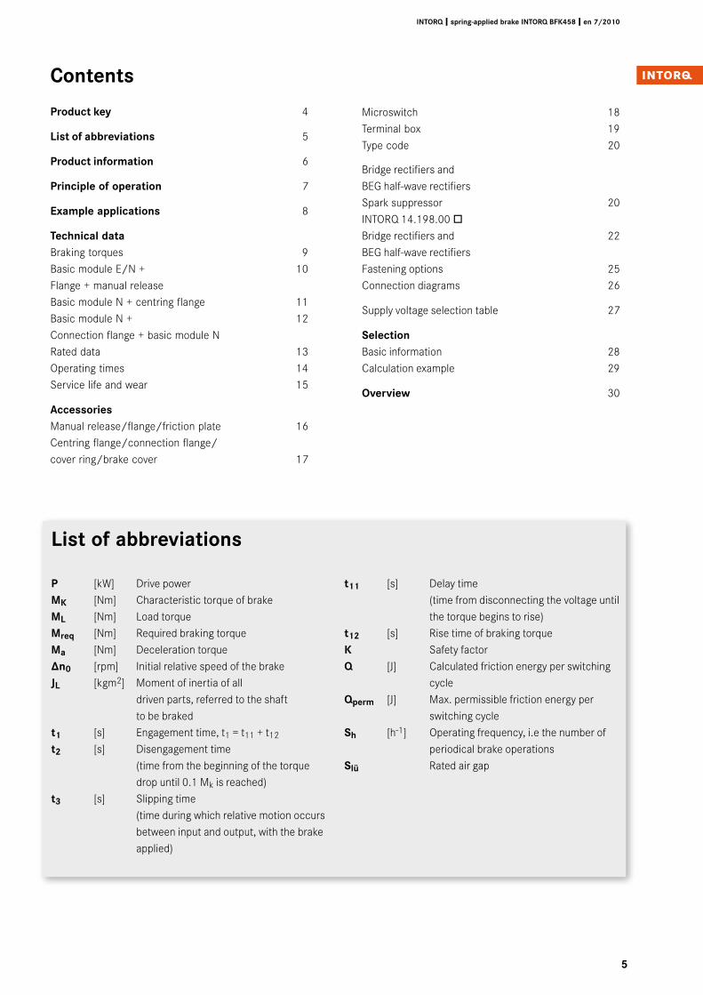
List of abbreviations
P [kW] Drive powerMK [Nm] Characteristic torque of brakeML [Nm] Load torqueMreq [Nm] Required braking torqueMa [Nm] Deceleration torque∆n0 [rpm] Initial relative speed of the brakeJL [kgm2] Moment of inertia of all
driven parts, referred to the shaft to be braked
t1 [s] Engagement time, t1 = t11 + t12
t� [s] Disengagement time (time from the beginning of the torque drop until 0.1 Mk is reached)t� [s] Slipping time
(time during which relative motion occurs between input and output, with the brake applied)
t11 [s] Delay time (time from disconnecting the voltage until the torque begins to rise)
t1� [s] Rise time of braking torqueK Safety factorQ [J] Calculated friction energy per switching cycleQperm [J] Max. permissible friction energy per
switching cycleSh [h-1] Operating frequency, i.e the number of periodical brake operationsSlü Rated air gap
Contents
Product key 4
List of abbreviations 5
Product information 6
Principle of operation 7
Example applications 8
Technical dataBraking torques 9Basic module E/N + 10Flange + manual release Basic module N + centring flange 11Basic module N + 12 Connection flange + basic module N Rated data 13Operating times 14Service life and wear 15
AccessoriesManual release/flange/friction plate 16 Centring flange/connection flange/ cover ring/brake cover 17
Microswitch 18Terminal box 19Type code 20
Bridge rectifiers and BEG half-wave rectifiers Spark suppressor 20INTORQ 14.198.00 ò Bridge rectifiers and 22BEG half-wave rectifiers Fastening options 25Connection diagrams 26
Supply voltage selection table 27
SelectionBasic information 28Calculation example 29
Overview 30
�
INTORQ I spring-applied brake INTORQ BFK458 I en 7/�010
Product information
A powerful and complete range| 9 sizes| Standard voltages 24 V, 96 V, 103 V, 170 V, 180 V,
190 V, 205 V| Graduated torque range from 1.5 - 600 Nm| Short delivery times for the complete range thanks to
optimised logistics| IP54 enclosure, depending on the particular
operating conditions| ATEX:
The product is suitable for use in potentially explosive atmospheres in zone II for stationary operation (holding or parking brake), explosion group II and temperature class T4.
Versatile| Modular structure for virtually all applications| Interchangeable with brake models 14.448 and 14.450
Torque transmission| Designed for dry running
Quick and easy mounting| Preset air gap| Special machining of the friction surfaces ensures that
the characteristics are achieved after very few switching operations
| No fixed bearing is required on the brake
Durable| The insulation system to temperature class F (155°C)
ensures that the winding has a long service life| The brakes are designed for 100% duty time (current
applied to the brake)
Low maintenance| Long rotor/hub connection with low rate of wear and a
tried-and-tested involute gear| Asbestos-free friction linings with low rate of wear
Reliable| The certified ISO 9001 and ISO 14001 quality system
provides the basis for consistently high-quality products| Production and testing to VDE 0580
Options| Manual release for all sizes, both directions can be used
for release and mounting (one exception is the tacho brake)
| Noise-reduced design| Various types of corrosion protection and enclosures| Microswitches used to monitor air gap and
wear (size 12 and above)| Monitoring of manual release function (page 19)| Non-standard voltages and bores on request
LongLife design – BFK458-L| Armature plate with low backlash and reinforced torque
support| Compression springs with guide pins for protection against
shearing forces| Aluminium rotor with toothed intermediate ring: Both the
friction lining and the tooth system have a low rate of wear
Temperature resistant to -40˚C | Use of chrome-plated friction surfaces (armature plate and
flange)| Use of temperature-resistant fixing screws is essential| Can also be combined with the noise-reduced rotor
INTORQ 155-1
E318895
to -40̊ C
7
INTORQ I spring-applied brake INTORQ BFK458 I en 7/�010
Principle of operation
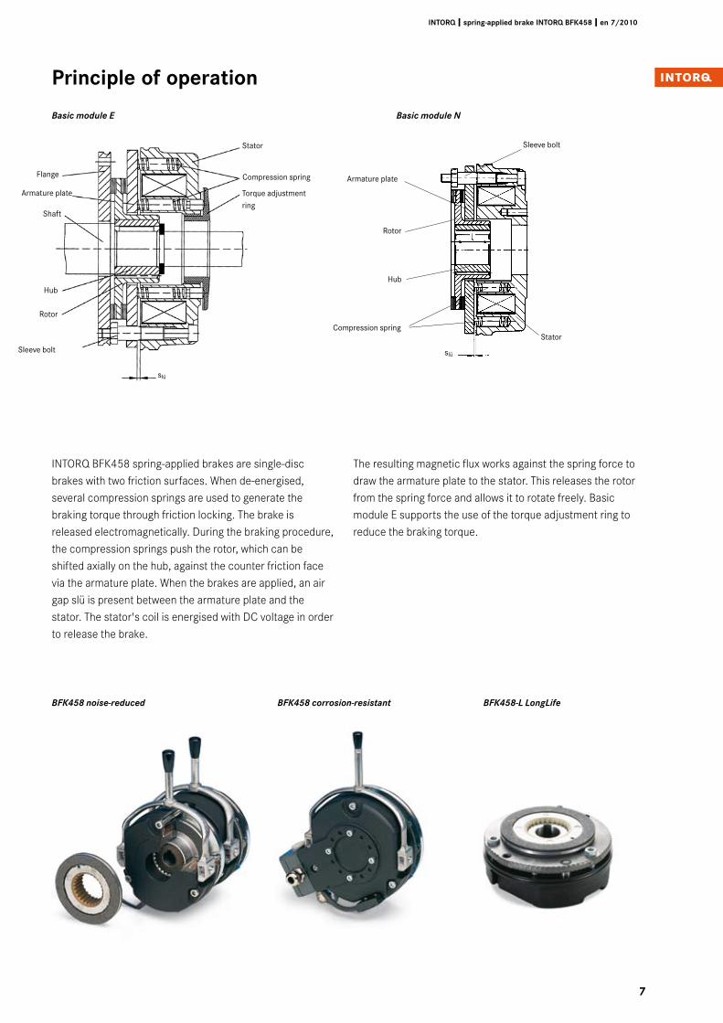
INTORQ BFK458 spring-applied brakes are single-disc brakes with two friction surfaces. When de-energised, several compression springs are used to generate the braking torque through friction locking. The brake is released electromagnetically. During the braking procedure, the compression springs push the rotor, which can be shifted axially on the hub, against the counter friction face via the armature plate. When the brakes are applied, an air gap slü is present between the armature plate and the stator. The stator's coil is energised with DC voltage in order to release the brake.
The resulting magnetic flux works against the spring force to draw the armature plate to the stator. This releases the rotor from the spring force and allows it to rotate freely. Basic module E supports the use of the torque adjustment ring to reduce the braking torque.
6
1
5
4
3
9
Basic module E Basic module N
9
7
Armature plate
slü
slü
Compression spring
Rotor
Hub
Shaft
Armature plate
Flange
Hub
Rotor
Stator
Stator
Compression spring
Torque adjustment ring
Sleeve bolt
slü
slü
Sleeve bolt
BFK458 noise-reduced BFK458 corrosion-resistant BFK458-L LongLife
8
INTORQ I spring-applied brake INTORQ BFK458 I en 7/�010
Example applications
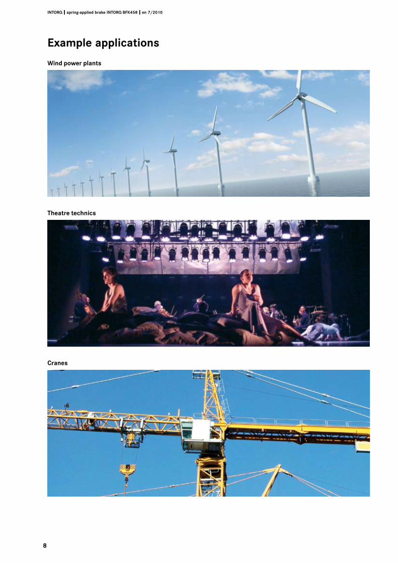
Wind power plants
Theatre technics
Cranes
�
INTORQ I spring-applied brake INTORQ BFK458 I en 7/�010
Technical data
Braking torques
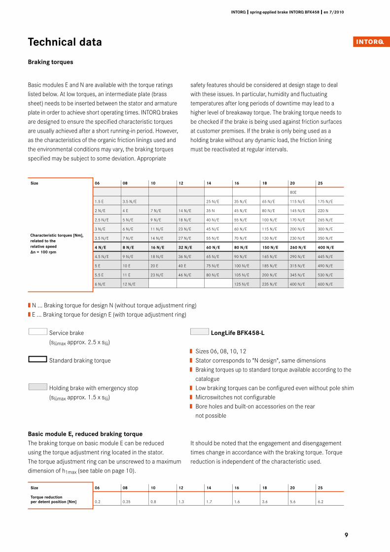
Basic modules E and N are available with the torque ratingslisted below. At low torques, an intermediate plate (brasssheet) needs to be inserted between the stator and armatureplate in order to achieve short operating times. INTORQ brakesare designed to ensure the specified characteristic torques are usually achieved after a short running-in period. However, as the characteristics of the organic friction linings used and the environmental conditions may vary, the braking torquesspecified may be subject to some deviation. Appropriate
safety features should be considered at design stage to dealwith these issues. In particular, humidity and fluctuatingtemperatures after long periods of downtime may lead to ahigher level of breakaway torque. The braking torque needs tobe checked if the brake is being used against friction surfacesat customer premises. If the brake is only being used as aholding brake without any dynamic load, the friction liningmust be reactivated at regular intervals.
Size 0� 08 10 1� 14 1� 18 �0 �5
Torque reduction per detent position [Nm] 0.2 0.35 0.8 1.3 1.7 1.6 3.6 5.6 6.2
Basic module E, reduced braking torqueThe braking torque on basic module E can be reduced using the torque adjustment ring located in the stator. The torque adjustment ring can be unscrewed to a maximum dimension of h1max (see table on page 10).
It should be noted that the engagement and disengagement times change in accordance with the braking torque. Torque reduction is independent of the characteristic used.
Size 0� 08 10 1� 14 1� 18 �0 �5
80E
1.5 E 3.5 N/E 25 N/E 35 N/E 65 N/E 115 N/E 175 N/E
2 N/E 4 E 7 N/E 14 N/E 35 N 45 N/E 80 N/E 145 N/E 220 N
2.5 N/E 5 N/E 9 N/E 18 N/E 40 N/E 55 N/E 100 N/E 170 N/E 265 N/E
3 N/E 6 N/E 11 N/E 23 N/E 45 N/E 60 N/E 115 N/E 200 N/E 300 N/E
3.5 N/E 7 N/E 14 N/E 27 N/E 55 N/E 70 N/E 130 N/E 230 N/E 350 N/E
4 N/E 8 N/E 1� N/E �� N/E �0 N/E 80 N/E 150 N/E ��0 N/E 400 N/E
4.5 N/E 9 N/E 18 N/E 36 N/E 65 N/E 90 N/E 165 N/E 290 N/E 445 N/E
5 E 10 E 20 E 40 E 75 N/E 100 N/E 185 N/E 315 N/E 490 N/E
5.5 E 11 E 23 N/E 46 N/E 80 N/E 105 N/E 200 N/E 345 N/E 530 N/E
6 N/E 12 N/E 125 N/E 235 N/E 400 N/E 600 N/E
Service brake (slümax approx. 2.5 x slü)
Standard braking torque
Holding brake with emergency stop (slümax approx. 1.5 x slü)
| N ... Braking torque for design N (without torque adjustment ring) | E ... Braking torque for design E (with torque adjustment ring)
Characteristic torques [Nm], related to the relative speed ∆n = 100 rpm
LongLife BFK458-L
| Sizes 06, 08, 10, 12| Stator corresponds to "N design", same dimensions| Braking torques up to standard torque available according to the catalogue| Low braking torques can be configured even without pole shim| Microswitches not configurable| Bore holes and built-on accessories on the rear not possible
10
INTORQ I spring-applied brake INTORQ BFK458 I en 7/�010
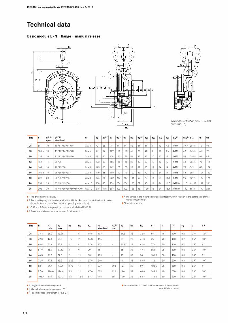
Size h h1 h1 h� h� h4 h5 h5-7) h� h7 h8 h� l l15) slü a b �)
min. max. standard max.
0� 36.3 39.3 43.25 1 6 15.8 107– 54.5 23 32.8 56.3 18 400 0.2 25° 12°
08 42.8 46.8 50.8 1.5 7 16.3 116 – 63 23 41.3 65 20 400 0.2 25° 10°
10 48.4 52.4 55.9 2 9 27.4 132 – 73.8 23 42.4 77.8 20 400 0.2 25° 9°
1� 54.9 58.9 67.53 2 9 29.4 161 – 85 23 47.4 88.5 25 400 0.3 25° 10°
14 66.3 71.3 77.3 2 11 33 195 – 98 32 50 101.5 30 400 0.3 25° 9°
1� 72.5 77.5 85.5 2.25 11 37.5 240 – 113 32 53.5 116 30 600 0.3 25° 10°
18 83.1 89.1 97.09 2.75 11 41.1 279 394 124 32 59.1 128.5 35 600 0.4 25° 9°
�0 97.6 104.6 114.6 3.5 11 47.6 319 416 146 32 68.6 149.5 40 600 0.4 25° 10°
�5 106.7 115.7 127.7 4.5 12.5 57.7 445 501 170 32 88.7 175.5 50 600 0.5 25° 10°
Size b dJ7 1) dH7 �) d1 d� d�H7 d5 d�j7 d7 d8 d�H8 d10 d11 d1� d1� d14�) d15�) d1� di da spec. standard
0� 88 10 10/11/12/14/15 3xM4 72 25 91 87 87 52 24 31 8 13 9.6 4xM4 37.7 3x4.5 40 60
08 106.5 10 11/12/14/15/20 3xM5 90 32 109 105 105 60 26 41 8 13 9.6 4xM5 49 3x5.5 47 77
10 132 10 11/12/14/15/20 3xM6 112 42 134 130 130 68 35 45 10 13 12 4xM5 54 3x6.6 66 95
1� 152 14 20/25 3xM6 132 50 155 150 150 82 40 52 10 13 12 4xM5 64 3x6.6 70 115
14 169 14 20/25/30 3xM8 145 60 169 165 165 92 52 55 12 24 14 4xM6 75 3x9 80 124
1� 194.5 15 25/30/35/38* 3xM8 170 68 195 190 190 102 52 70 12 24 14 4xM6 85 3x9 104 149
18 222 20 30/35/40/45 6xM8 196 75 222 217 217 116 62 77 14 24 15.5 4xM8 95 4x94) 129 174
�0 258 25 35/40/45/50 6xM10 230 85 259 254 254 135 72 90 14 24 16.5 4xM10 110 4x114) 148 206
�5 302 30 40/45/50/55/60/65/70* 6xM10 278 115 307 302 302 165 85 120 16 24 18.4 4xM10 140 6x11 199 254
slü
Thickness of friction plate: 1.5 mm (sizes 06-16)
| 1) Pre-drilled without keyway
| 2) Standard keyway in accordance with DIN 6885/1 P9, selection of the shaft diameter dependent upon type of load (see the operating instructions)
| * Ø 38 and Ø 70 mm, keyway in accordance with DIN 6885/3 P9
| 3) Bores are made on customer request for sizes 6 – 12
| 4) The thread in the mounting surface is offset by 30° in relation to the centre axis of the manual release lever
| Dimensions in mm
| 5) Length of the connecting cable
| 6) Manual release angle tolerance +3°
| 7) Recommended lever length for 1.5 MK
| Recommended ISO shaft tolerances: up to Ø 50 mm = k6 over Ø 50 mm = m6
Technical data
Basic module E/N + flange + manual release
11
INTORQ I spring-applied brake INTORQ BFK458 I en 7/�010
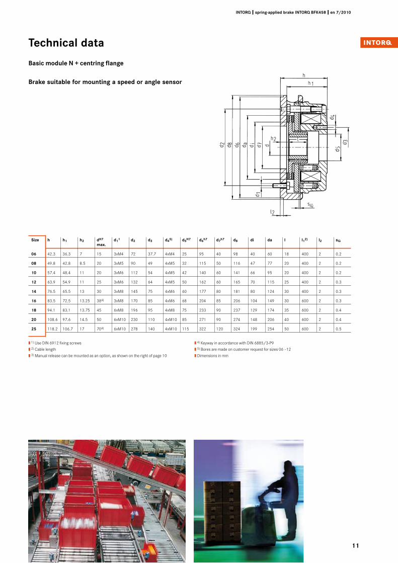
Size h h1 h� dH7 d11 d� d� d45) d5H7 d�h7 d7h7 d8 di da l l1�) l� slü max.
0� 42.3 36.3 7 15 3xM4 72 37.7 4xM4 25 95 40 98 40 60 18 400 2 0.2
08 49.8 42.8 8.5 20 3xM5 90 49 4xM5 32 115 50 116 47 77 20 400 2 0.2
10 57.4 48.4 11 20 3xM6 112 54 4xM5 42 140 60 141 66 95 20 400 2 0.2
1� 63.9 54.9 11 25 3xM6 132 64 4xM5 50 162 60 165 70 115 25 400 2 0.3
14 76.5 65.5 13 30 3xM8 145 75 4xM6 60 177 80 181 80 124 30 400 2 0.3
1� 83.5 72.5 13.25 384) 3xM8 170 85 4xM6 68 204 85 206 104 149 30 600 2 0.3
18 94.1 83.1 13.75 45 6xM8 196 95 4xM8 75 233 90 237 129 174 35 600 2 0.4
�0 108.6 97.6 14.5 50 6xM10 230 110 4xM10 85 271 90 274 148 206 40 600 2 0.4
�5 118.2 106.7 17 704) 6xM10 278 140 4xM10 115 322 120 324 199 254 50 600 2 0.5
| 1) Use DIN 6912 fixing screws
| 2) Cable length
| 3) Manual release can be mounted as an option, as shown on the right of page 10
| 4) Keyway in accordance with DIN 6885/3-P9
| 5) Bores are made on customer request for sizes 06 –12
| Dimensions in mm
Technical data
Basic module N + centring flange
Brake suitable for mounting a speed or angle sensor
1�
INTORQ I spring-applied brake INTORQ BFK458 I en 7/�010
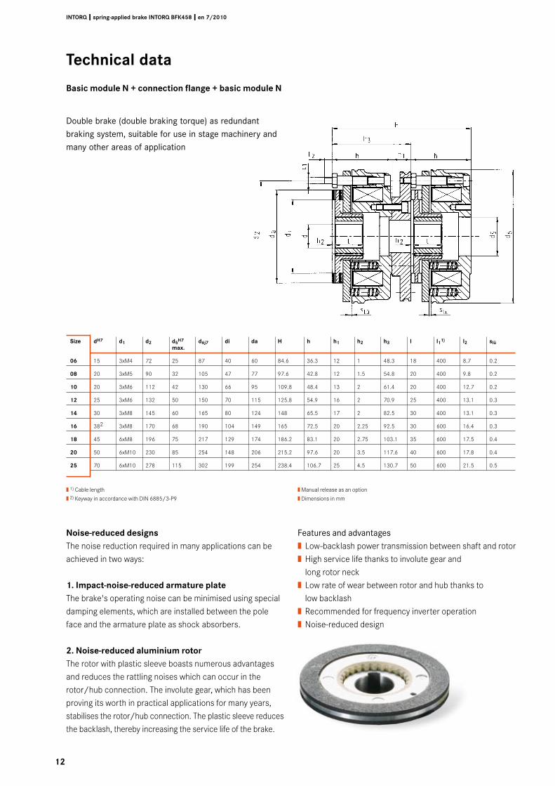
Size dH7 d1 d� d5H7 d�j7 di da H h h1 h� h� l l11) l� slü max.
0� 15 3xM4 72 25 87 40 60 84.6 36.3 12 1 48.3 18 400 8.7 0.2
08 20 3xM5 90 32 105 47 77 97.6 42.8 12 1.5 54.8 20 400 9.8 0.2
10 20 3xM6 112 42 130 66 95 109.8 48.4 13 2 61.4 20 400 12.7 0.2
1� 25 3xM6 132 50 150 70 115 125.8 54.9 16 2 70.9 25 400 13.1 0.3
14 30 3xM8 145 60 165 80 124 148 65.5 17 2 82.5 30 400 13.1 0.3
1� 382 3xM8 170 68 190 104 149 165 72.5 20 2.25 92.5 30 600 16.4 0.3
18 45 6xM8 196 75 217 129 174 186.2 83.1 20 2.75 103.1 35 600 17.5 0.4
�0 50 6xM10 230 85 254 148 206 215.2 97.6 20 3.5 117.6 40 600 17.8 0.4
�5 70 6xM10 278 115 302 199 254 238.4 106.7 25 4.5 130.7 50 600 21.5 0.5
| 1) Cable length
| 2) Keyway in accordance with DIN 6885/3-P9
| Manual release as an option
| Dimensions in mm
Technical data
Basic module N + connection flange + basic module N
Noise-reduced designsThe noise reduction required in many applications can be achieved in two ways:
1. Impact-noise-reduced armature plateThe brake's operating noise can be minimised using special damping elements, which are installed between the pole face and the armature plate as shock absorbers.
�. Noise-reduced aluminium rotorThe rotor with plastic sleeve boasts numerous advantages and reduces the rattling noises which can occur in the rotor/hub connection. The involute gear, which has been proving its worth in practical applications for many years, stabilises the rotor/hub connection. The plastic sleeve reduces the backlash, thereby increasing the service life of the brake.
Features and advantages| Low-backlash power transmission between shaft and rotor| High service life thanks to involute gear and long rotor neck| Low rate of wear between rotor and hub thanks to low backlash| Recommended for frequency inverter operation| Noise-reduced design
Double brake (double braking torque) as redundant braking system, suitable for use in stage machinery and many other areas of application
1�
INTORQ I spring-applied brake INTORQ BFK458 I en 7/�010
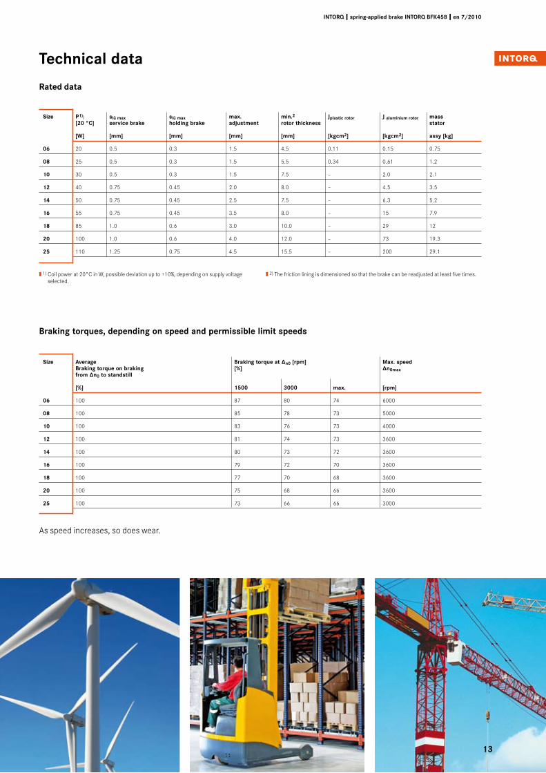
Size Average Braking torque at ∆n0 [rpm] Max. speed Braking torque on braking [%] ∆n0max from ∆n0 to standstill
[%] 1500 �000 max. [rpm]
0� 100 87 80 74 6000
08 100 85 78 73 5000
10 100 83 76 73 4000
1� 100 81 74 73 3600
14 100 80 73 72 3600
1� 100 79 72 70 3600
18 100 77 70 68 3600
�0 100 75 68 66 3600
�5 100 73 66 66 3000
Size P1)) slü max slü max max. min.� Jplastic rotor J aluminium rotor mass [�0 °C] service brake holding brake adjustment rotor thickness stator
[W] [mm] [mm] [mm] [mm] [kgcm�] [kgcm�] assy [kg]
0� 20 0.5 0.3 1.5 4.5 0.11 0.15 0.75
08 25 0.5 0.3 1.5 5.5 0.34 0.61 1.2
10 30 0.5 0.3 1.5 7.5 – 2.0 2.1
1� 40 0.75 0.45 2.0 8.0 – 4.5 3.5
14 50 0.75 0.45 2.5 7.5 – 6.3 5.2
1� 55 0.75 0.45 3.5 8.0 – 15 7.9
18 85 1.0 0.6 3.0 10.0 – 29 12
�0 100 1.0 0.6 4.0 12.0 – 73 19.3
�5 110 1.25 0.75 4.5 15.5 – 200 29.1
Braking torques, depending on speed and permissible limit speeds
Technical data
Rated data
| 1) Coil power at 20°C in W, possible deviation up to +10%, depending on supply voltage selected.
| 2) The friction lining is dimensioned so that the brake can be readjusted at least five times.
As speed increases, so does wear.
14
INTORQ I spring-applied brake INTORQ BFK458 I en 7/�010
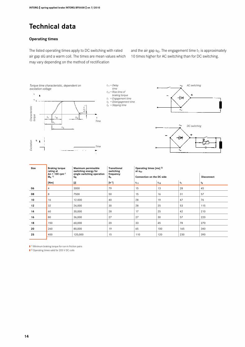
Size Braking torque Maximum permissible Transitional Operating times [ms] �) rating at switching energy for switching at slür ∆n = 100 rpm-1 single switching operation frequency MK 1) QE Sh Connection on the DC side Disconnect
[Nm] [J] [h-1] t11 t1� t1 t�
0� 4 3000 79 15 13 28 45
08 8 7500 50 15 16 31 57
10 16 12.000 40 28 19 47 76
1� 32 24,000 30 28 25 53 115
14 60 30,000 28 17 25 42 210
1� 80 36,000 27 27 30 57 220
18 150 60,000 20 33 45 78 270
�0 260 80,000 19 65 100 165 340
�5 400 120,000 15 110 120 230 390
The listed operating times apply to DC switching with rated air gap slü and a warm coil. The times are mean values which may vary depending on the method of rectification
and the air gap slü. The engagement time t1 is approximately 10 times higher for AC switching than for DC switching.
| 1) Minimum braking torque for run-in friction pairs
| 2) Operating times valid for 205 V DC coils
AC switching
DC switching
t11 = Delay time
t12 = Rise time of braking torque
t1 = Engagement timet2 = Disengagement timet3 = Slipping time
Torque time characteristic, dependent on excitation voltage
Cha
ract
eris
tic
torq
ueEx
cita
tion
Time
Time
Technical data
Operating times
15
INTORQ I spring-applied brake INTORQ BFK458 I en 7/�010
Technical data
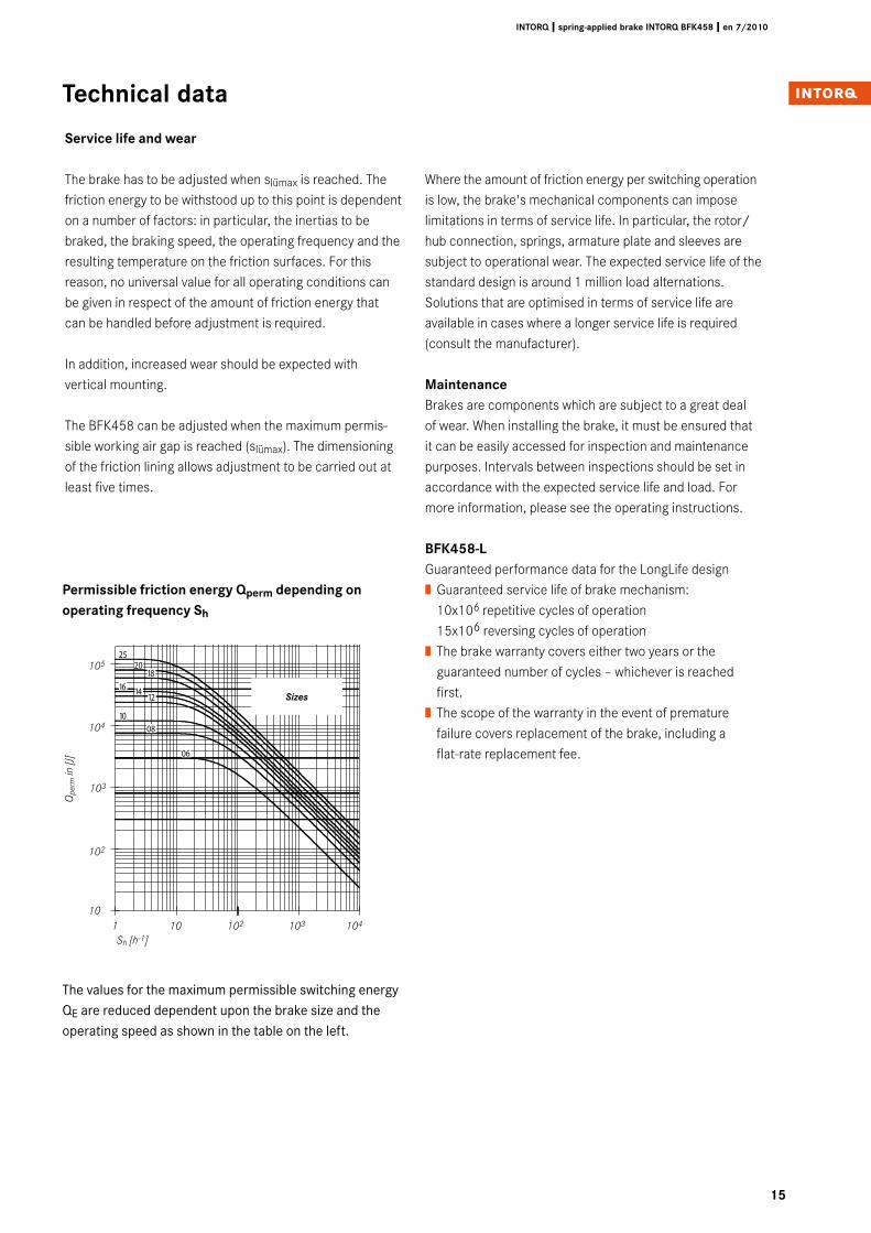
Permissible friction energy Qperm depending on operating frequency Sh
Service life and wear
The brake has to be adjusted when slümax is reached. The friction energy to be withstood up to this point is dependent on a number of factors: in particular, the inertias to be braked, the braking speed, the operating frequency and the resulting temperature on the friction surfaces. For this reason, no universal value for all operating conditions can be given in respect of the amount of friction energy that can be handled before adjustment is required.
In addition, increased wear should be expected with vertical mounting.
The BFK458 can be adjusted when the maximum permis-sible working air gap is reached (slümax). The dimensioning of the friction lining allows adjustment to be carried out at least five times.
Where the amount of friction energy per switching operation is low, the brake's mechanical components can impose limitations in terms of service life. In particular, the rotor/hub connection, springs, armature plate and sleeves are subject to operational wear. The expected service life of the standard design is around 1 million load alternations. Solutions that are optimised in terms of service life are available in cases where a longer service life is required (consult the manufacturer).
MaintenanceBrakes are components which are subject to a great deal of wear. When installing the brake, it must be ensured that it can be easily accessed for inspection and maintenance purposes. Intervals between inspections should be set in accordance with the expected service life and load. For more information, please see the operating instructions.
BFK458-LGuaranteed performance data for the LongLife design| Guaranteed service life of brake mechanism: 10x106 repetitive cycles of operation 15x106 reversing cycles of operation| The brake warranty covers either two years or the guaranteed number of cycles – whichever is reached first.| The scope of the warranty in the event of premature failure covers replacement of the brake, including a flat-rate replacement fee.
10
100
1.000
10.000
100.000
1.000.000
1 10 100 1.000 10.000
Schalthäufigkeit Sh [h-1]
Sch
alta
rbei
t Q
[J]
2520
1816 14
12
1008
06
Sh [h-1]
105
104
103
102
Qpe
rm in
[J]
Sizes
1 10 102 103 10410
The values for the maximum permissible switching energy QE are reduced dependent upon the brake size and the operating speed as shown in the table on the left.
1�
INTORQ I spring-applied brake INTORQ BFK458 I en 7/�010
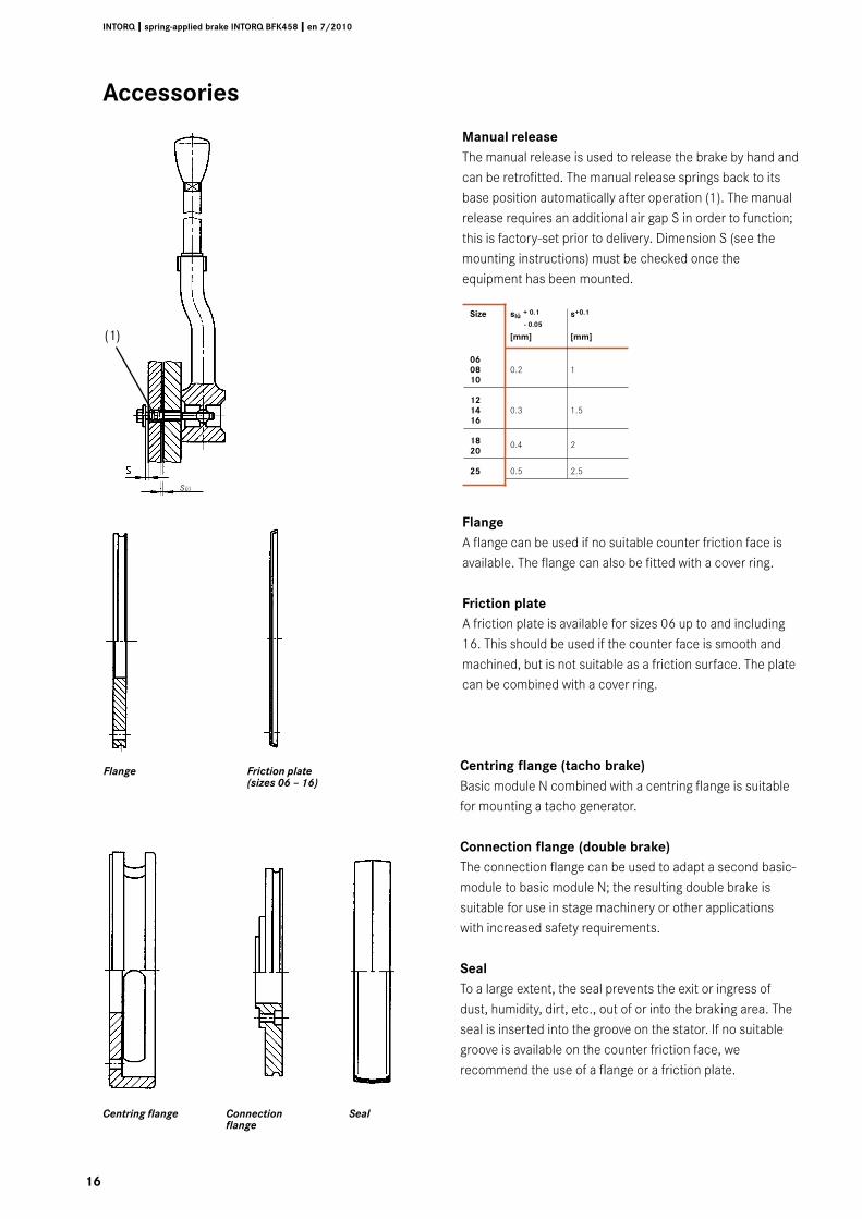
Size slü + 0.1 s+0.1
- 0.05
[mm] [mm]
0� 08 0.2 1 10
1� 14 0.3 1.5 1�
18 0.4 2 �0
�5 0.5 2.5
slü
Accessories
Manual releaseThe manual release is used to release the brake by hand and can be retrofitted. The manual release springs back to its base position automatically after operation (1). The manual release requires an additional air gap S in order to function; this is factory-set prior to delivery. Dimension S (see the mounting instructions) must be checked once the equipment has been mounted.
FlangeA flange can be used if no suitable counter friction face is available. The flange can also be fitted with a cover ring.
Friction plateA friction plate is available for sizes 06 up to and including 16. This should be used if the counter face is smooth and machined, but is not suitable as a friction surface. The plate can be combined with a cover ring.
Flange Friction plate (sizes 06 – 16)
Centring flange (tacho brake)Basic module N combined with a centring flange is suitable for mounting a tacho generator.
Connection flange (double brake)The connection flange can be used to adapt a second basic-module to basic module N; the resulting double brake is suitable for use in stage machinery or other applications with increased safety requirements.
SealTo a large extent, the seal prevents the exit or ingress of dust, humidity, dirt, etc., out of or into the braking area. The seal is inserted into the groove on the stator. If no suitable groove is available on the counter friction face, we recommend the use of a flange or a friction plate.
SealConnection flange
Centring flange
(1)
17
INTORQ I spring-applied brake INTORQ BFK458 I en 7/�010
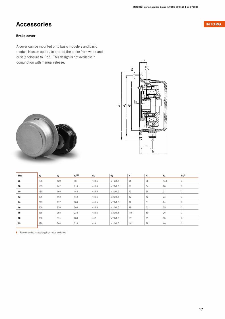
Size d1 d� d�H8 d4 d5 h h1 h� h�1)
0� 135 120 98 4x4.5 M16x1.5 55 28 16.5 3
08 155 142 118 4x5.5 M20x1.5 61 34 20 3
10 185 166 143 4x5.5 M20x1.5 72 39 21 3
1� 205 192 163 4x6.6 M20x1.5 82 42 23 3
14 225 212 183 4x6.6 M20x1.5 92 51 24 3
1� 250 236 208 4x6.6 M20x1.5 98 52 25 3
18 285 268 238 4x6.6 M20x1.5 115 60 29 3
�0 330 314 283 4x9 M20x1.5 131 69 35 3
�5 390 368 328 4x9 M20x1.5 142 78 40 3
A cover can be mounted onto basic module E and basic module N as an option, to protect the brake from water and dust (enclosure to IP65). This design is not available in conjunction with manual release.
| 1) Recommended recess length on motor endshield
Accessories
Brake cover
18
INTORQ I spring-applied brake INTORQ BFK458 I en 7/�010
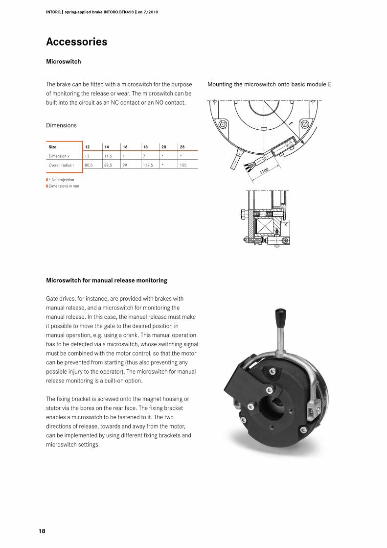
Size 1� 14 1� 18 �0 �5
Dimension x 13 11.5 11 7 * *
Overall radius r 80.5 88.5 99 112.5 * 155
| * No projection
| Dimensions in mm
The brake can be fitted with a microswitch for the purpose of monitoring the release or wear. The microswitch can be built into the circuit as an NC contact or an NO contact.
Dimensions
Mounting the microswitch onto basic module E
Accessories
Microswitch
Microswitch for manual release monitoring
Gate drives, for instance, are provided with brakes with manual release, and a microswitch for monitoring the manual release. In this case, the manual release must make it possible to move the gate to the desired position in manual operation, e.g. using a crank. This manual operation has to be detected via a microswitch, whose switching signal must be combined with the motor control, so that the motor can be prevented from starting (thus also preventing any possible injury to the operator). The microswitch for manual release monitoring is a built-on option.
The fixing bracket is screwed onto the magnet housing or stator via the bores on the rear face. The fixing bracket enables a microswitch to be fastened to it. The two directions of release, towards and away from the motor, can be implemented by using different fixing brackets and microswitch settings.
1�
INTORQ I spring-applied brake INTORQ BFK458 I en 7/�010
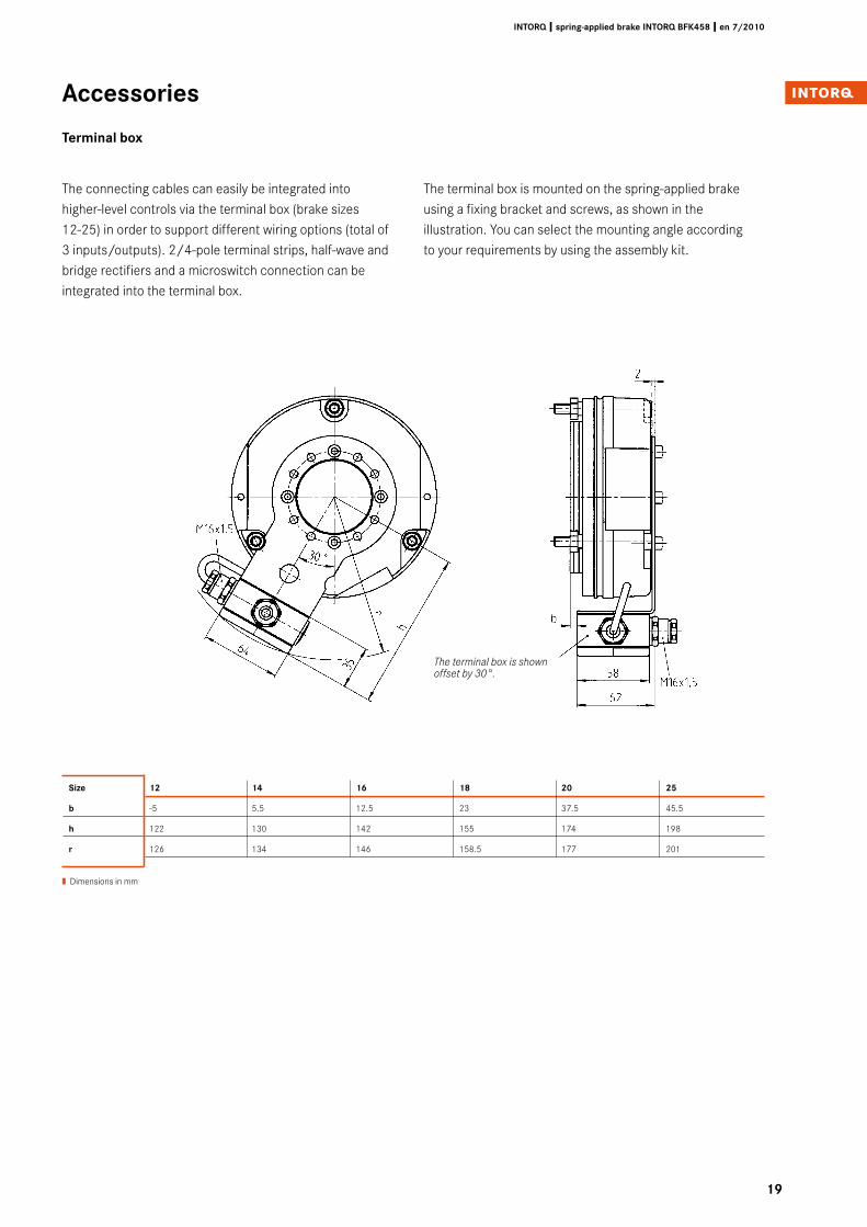
Size 1� 14 1� 18 �0 �5
b -5 5.5 12.5 23 37.5 45.5
h 122 130 142 155 174 198
r 126 134 146 158.5 177 201
The connecting cables can easily be integrated into higher-level controls via the terminal box (brake sizes 12-25) in order to support different wiring options (total of 3 inputs/outputs). 2/4-pole terminal strips, half-wave and bridge rectifiers and a microswitch connection can be integrated into the terminal box.
The terminal box is shown offset by 30°.
| Dimensions in mm
The terminal box is mounted on the spring-applied brake using a fixing bracket and screws, as shown in the illustration. You can select the mounting angle according to your requirements by using the assembly kit.
Accessories
Terminal box
�0
INTORQ I spring-applied brake INTORQ BFK458 I en 7/�010
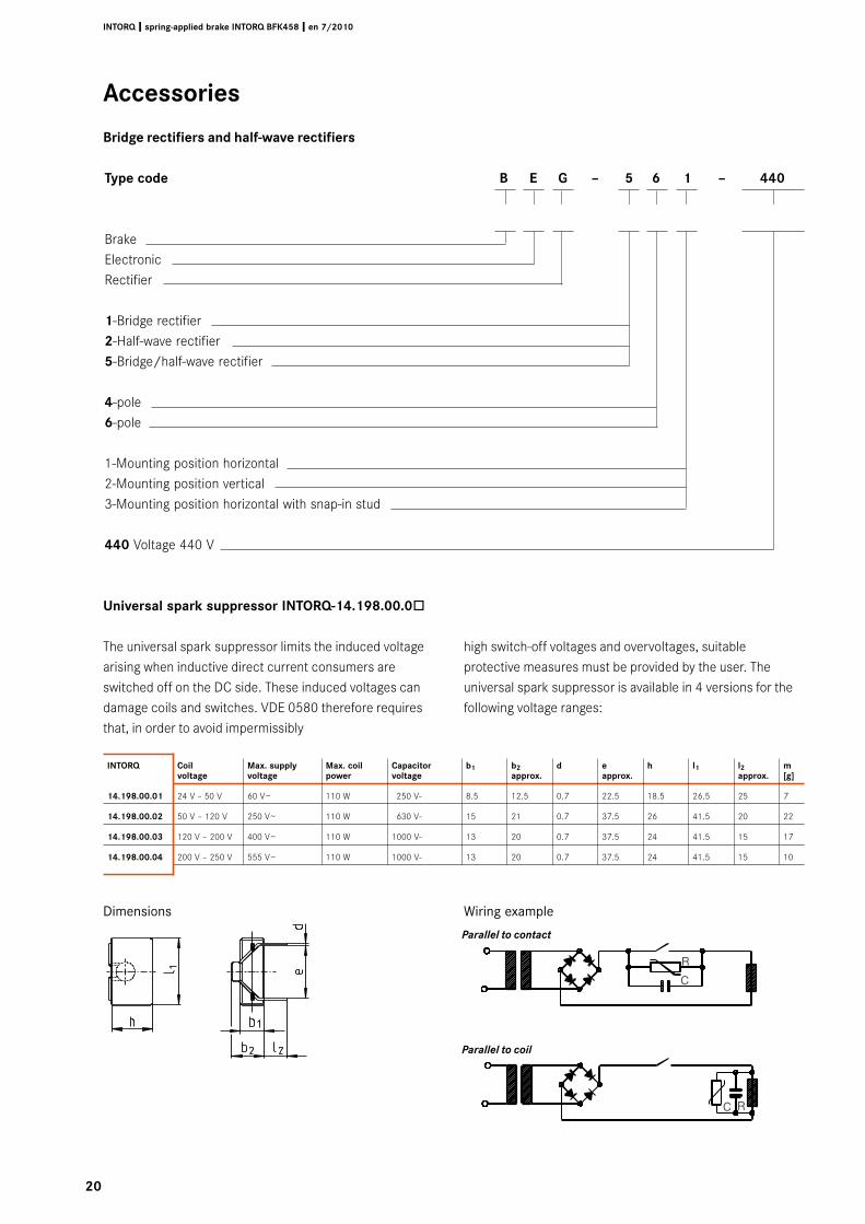
Type code B E G – 5 � 1 – 440
BrakeElectronicRectifier
1-Bridge rectifier�-Half-wave rectifier5-Bridge/half-wave rectifier
4-pole�-pole
1-Mounting position horizontal2-Mounting position vertical3-Mounting position horizontal with snap-in stud
440 Voltage 440 V
Accessories
Bridge rectifiers and half-wave rectifiers
Universal spark suppressor INTORQ-14.1�8.00.0ò
The universal spark suppressor limits the induced voltage arising when inductive direct current consumers are switched off on the DC side. These induced voltages can damage coils and switches. VDE 0580 therefore requires that, in order to avoid impermissibly
high switch-off voltages and overvoltages, suitable protective measures must be provided by the user. The universal spark suppressor is available in 4 versions for the following voltage ranges:
INTORQ Coil Max. supply Max. coil Capacitor b1 b� d e h l1 l� m voltage voltage power voltage approx. approx. approx. [g]
14.1�8.00.01 24 V – 50 V 60 V~ 110 W 250 V- 8.5 12.5 0.7 22.5 18.5 26.5 25 7
14.1�8.00.0� 50 V – 120 V 250 V~ 110 W 630 V- 15 21 0.7 37.5 26 41.5 20 22
14.1�8.00.0� 120 V – 200 V 400 V~ 110 W 1000 V- 13 20 0.7 37.5 24 41.5 15 17
14.1�8.00.04 200 V – 250 V 555 V~ 110 W 1000 V- 13 20 0.7 37.5 24 41.5 15 10
Dimensions Wiring example
Parallel to contact
Parallel to coil
�1
INTORQ I spring-applied brake INTORQ BFK458 I en 7/�010
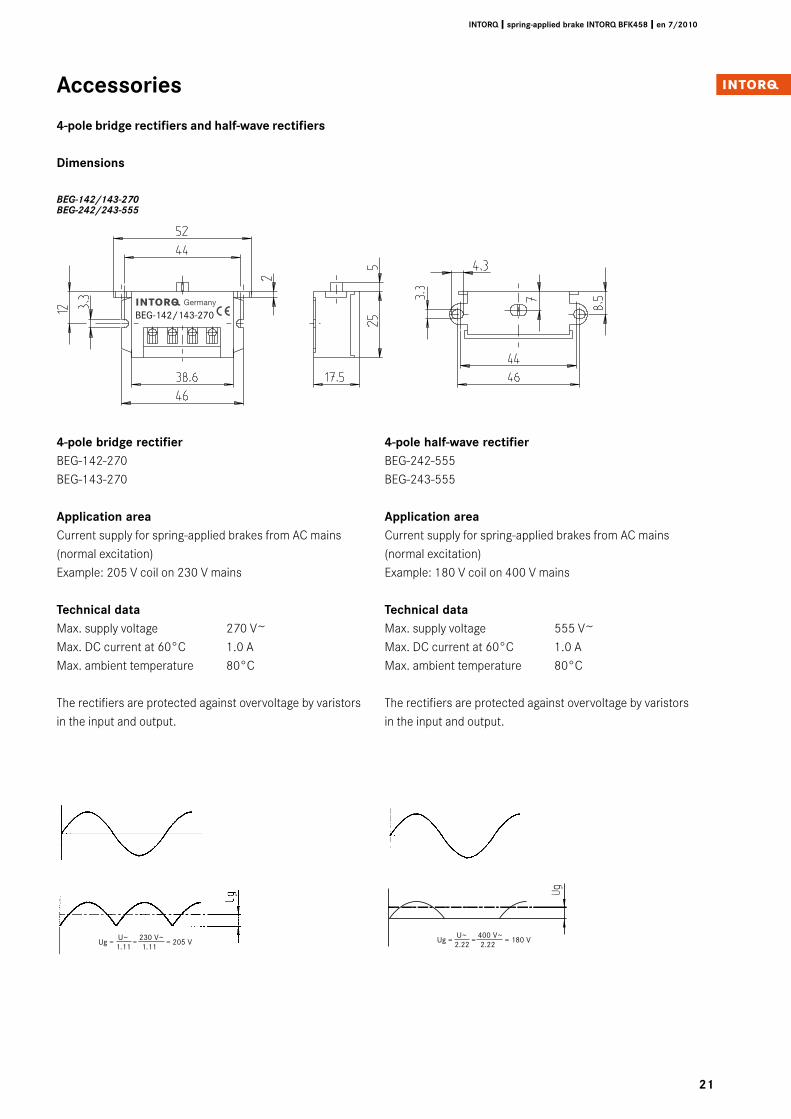
4-pole bridge rectifierBEG-142-270 BEG-143-270
Application areaCurrent supply for spring-applied brakes from AC mains (normal excitation)Example: 205 V coil on 230 V mains
Technical dataMax. supply voltage 270 V~Max. DC current at 60°C 1.0 AMax. ambient temperature 80°C
The rectifiers are protected against overvoltage by varistors in the input and output.
BEG-142/143-270
Ug = U~
= 230 V~
= 205 V 1.11 1.11
Ug = U~
= 400 V~
= 180 V 2.22 2.22
4-pole half-wave rectifierBEG-242-555BEG-243-555
Application areaCurrent supply for spring-applied brakes from AC mains (normal excitation)Example: 180 V coil on 400 V mains
Technical dataMax. supply voltage 555 V~Max. DC current at 60°C 1.0 AMax. ambient temperature 80°C
The rectifiers are protected against overvoltage by varistors in the input and output.
BEG-142/143-270BEG-242/243-555
Accessories
4-pole bridge rectifiers and half-wave rectifiers
Dimensions
��
INTORQ I spring-applied brake INTORQ BFK458 I en 7/�010
Accessories
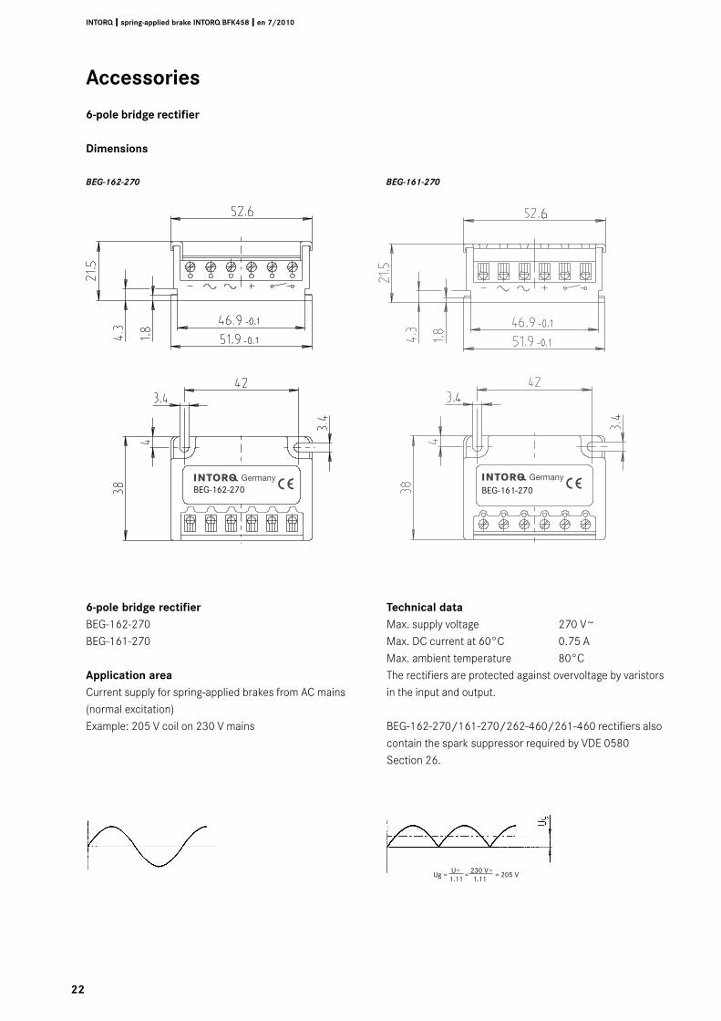
�-pole bridge rectifier
Dimensions
BEG-162-270 BEG-161-270
�-pole bridge rectifierBEG-162-270BEG-161-270
Application areaCurrent supply for spring-applied brakes from AC mains (normal excitation)Example: 205 V coil on 230 V mains
Technical dataMax. supply voltage 270 V~Max. DC current at 60°C 0.75 AMax. ambient temperature 80°CThe rectifiers are protected against overvoltage by varistors in the input and output.
BEG-162-270/161-270/262-460/261-460 rectifiers also contain the spark suppressor required by VDE 0580 Section 26.
Ug = U~
= 230 V~
= 205 V 1.11 1.11
BEG-162-270 BEG-161-270BEG-162-270 BEG-161-270
��
INTORQ I spring-applied brake INTORQ BFK458 I en 7/�010
Accessories
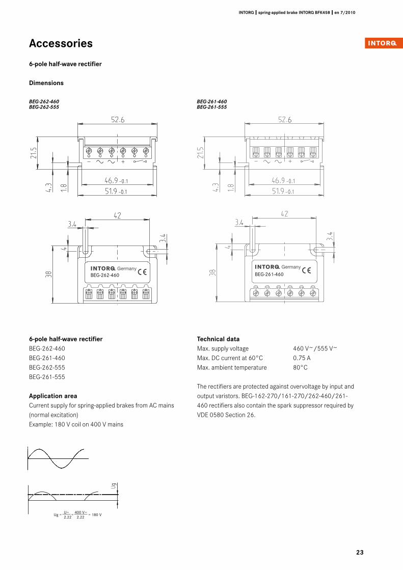
�-pole half-wave rectifier
Dimensions
�-pole half-wave rectifierBEG-262-460BEG-261-460BEG-262-555 BEG-261-555
Application areaCurrent supply for spring-applied brakes from AC mains (normal excitation)Example: 180 V coil on 400 V mains
Technical dataMax. supply voltage 460 V~/555 V~Max. DC current at 60°C 0.75 AMax. ambient temperature 80°C
The rectifiers are protected against overvoltage by input and output varistors. BEG-162-270/161-270/262-460/261-460 rectifiers also contain the spark suppressor required by VDE 0580 Section 26.
Ug = U~
= 400 V~
= 180 V 2.22 2.22
BEG-262-460 BEG-261-460BEG-262-555 BEG-261-555
BEG-262-460 BEG-261-460BEG-262-460 BEG-261-460
�4
INTORQ I spring-applied brake INTORQ BFK458 I en 7/�010
Accessories
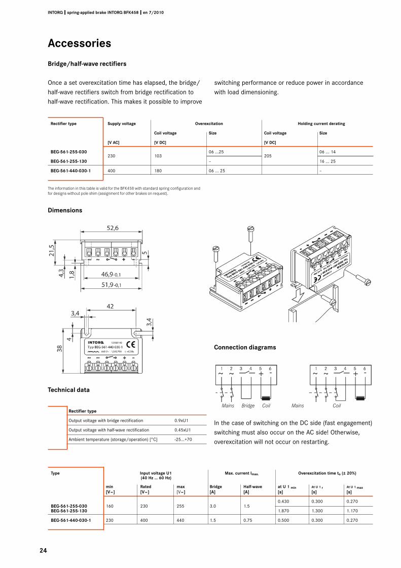
Bridge/half-wave rectifiers
Once a set overexcitation time has elapsed, the bridge/half-wave rectifiers switch from bridge rectification to half-wave rectification. This makes it possible to improve
switching performance or reduce power in accordance with load dimensioning.
The information in this table is valid for the BFK458 with standard spring configuration and for designs without pole shim (assignment for other brakes on request).
Dimensions
Rectifier type Supply voltage Overexcitation Holding current derating Coil voltage Size Coil voltage Size
[V AC] [V DC] [V DC]
BEG-5�1-�55-0�0 230 103
06 ...25 205
06 ... 14
BEG-5�1-�55-1�0 – 16 ... 25
BEG-5�1-440-0�0-1 400 180 06 ... 25 –
Rectifier type
Output voltage with bridge rectification 0.9xU1
Output voltage with half-wave rectification 0.45xU1
Ambient temperature (storage/operation) [°C] -25...+70
Technical data
Connection diagrams
Mains Bridge Coil Mains Coil
In the case of switching on the DC side (fast engagement) switching must also occur on the AC side! Otherwise, overexcitation will not occur on restarting.
Type Input voltage U1 Max. current lmax. Overexcitation time to (± �0%) (40 Hz ... �0 Hz)
min Rated max Bridge Half-wave at U 1 min At U 1 r At U 1 max [V~] [V~] [V~] [A] [A] [s] [s] [s]
BEG-5�1-�55-0�0 160 230 255 3.0 1.5 0.430 0.300 0.270
BEG-5�1-�55-1�0 1.870 1.300 1.170
BEG-5�1-440-0�0-1 230 400 440 1.5 0.75 0.500 0.300 0.270
�5
INTORQ I spring-applied brake INTORQ BFK458 I en 7/�010
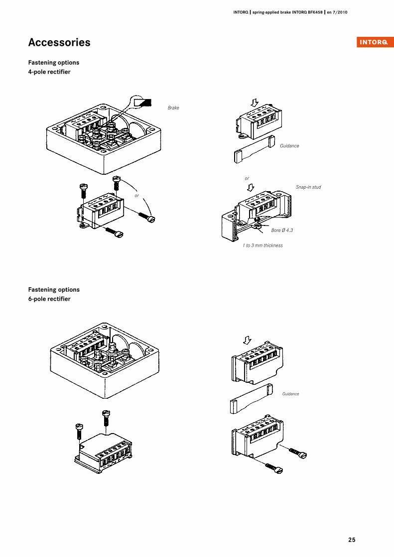
Accessories
Fastening options4-pole rectifier
Brake
or
Snap-in stud
Bore Ø 4.3
1 to 3 mm thickness
Guidance
Guidance
or
Fastening options�-pole rectifier
��
INTORQ I spring-applied brake INTORQ BFK458 I en 7/�010
Accessories
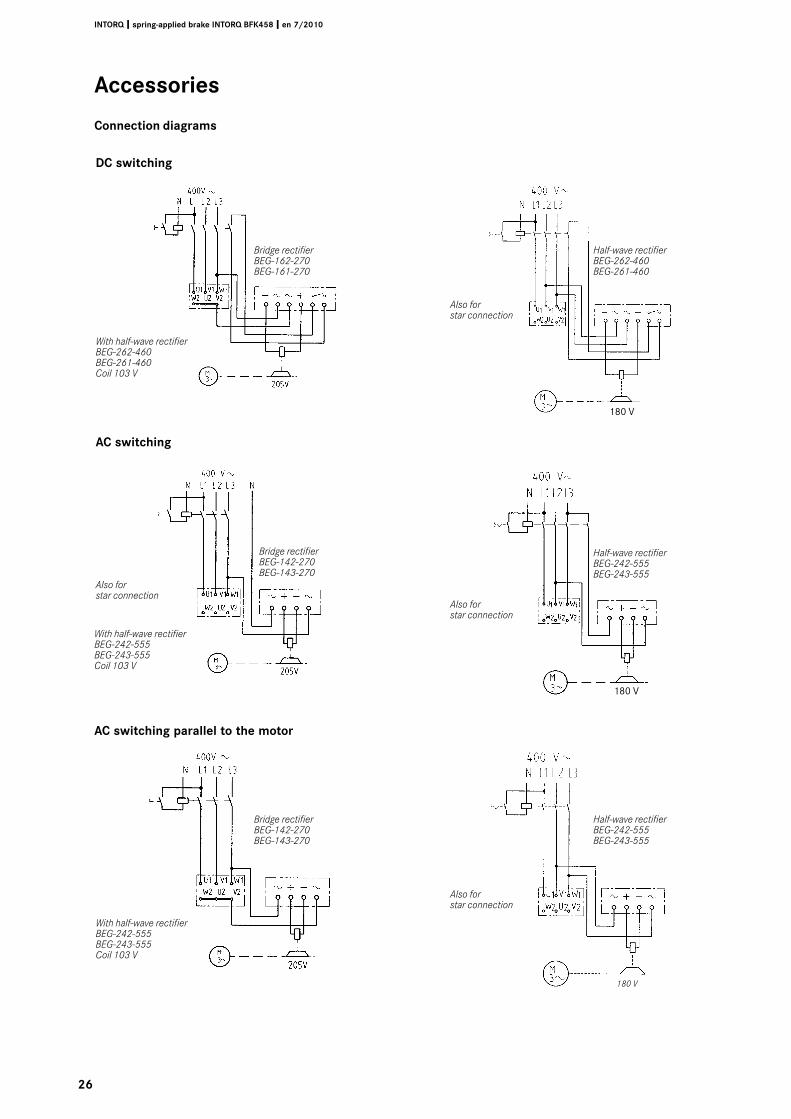
Connection diagrams
DC switching
AC switching
Bridge rectifierBEG-162-270BEG-161-270
Bridge rectifierBEG-142-270BEG-143-270
Bridge rectifierBEG-142-270BEG-143-270
Half-wave rectifierBEG-262-460BEG-261-460
Half-wave rectifierBEG-242-555BEG-243-555
Half-wave rectifierBEG-242-555BEG-243-555
With half-wave rectifier BEG-262-460BEG-261-460Coil 103 V
180 V
180 V
With half-wave rectifier BEG-242-555BEG-243-555 Coil 103 V
With half-wave rectifier BEG-242-555BEG-243-555 Coil 103 V
Also for star connection
Also for star connection
Also for star connection
Also for star connection
180 V
AC switching parallel to the motor
�7
INTORQ I spring-applied brake INTORQ BFK458 I en 7/�010
Accessories
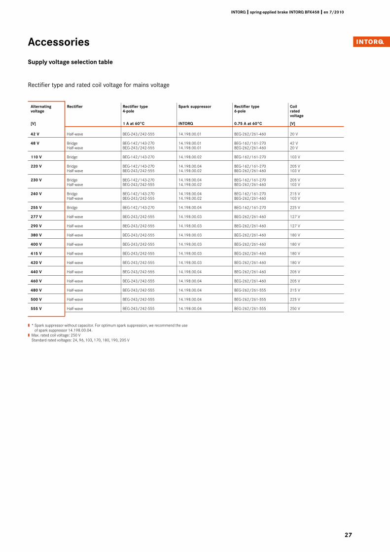
Supply voltage selection table
Alternating Rectifier Rectifier type Spark suppressor Rectifier type Coil voltage 4-pole �-pole rated voltage
[V] 1 A at �0°C INTORQ 0.75 A at �0°C [V]
4� V Half-wave BEG-243/242-555 14.198.00.01 BEG-262/261-460 20 V
48 V Bridge BEG-142/143-270 14.198.00.01 BEG-162/161-270 42 V Half-wave BEG-243/242-555 14.198.00.01 BEG-262/261-460 20 V
110 V Bridge BEG-142/143-270 14.198.00.02 BEG-162/161-270 103 V
��0 V Bridge BEG-142/143-270 14.198.00.04 BEG-162/161-270 205 V Half-wave BEG-243/242-555 14.198.00.02 BEG-262/261-460 103 V
��0 V Bridge BEG-142/143-270 14.198.00.04 BEG-162/161-270 205 V Half-wave BEG-243/242-555 14.198.00.02 BEG-262/261-460 103 V
�40 V Bridge BEG-142/143-270 14.198.00.04 BEG-162/161-270 215 V Half-wave BEG-243/242-555 14.198.00.02 BEG-262/261-460 103 V
�55 V Bridge BEG-142/143-270 14.198.00.04 BEG-162/161-270 225 V
�77 V Half-wave BEG-243/242-555 14.198.00.03 BEG-262/261-460 127 V
��0 V Half-wave BEG-243/242-555 14.198.00.03 BEG-262/261-460 127 V
�80 V Half-wave BEG-243/242-555 14.198.00.03 BEG-262/261-460 180 V
400 V Half-wave BEG-243/242-555 14.198.00.03 BEG-262/261-460 180 V
415 V Half-wave BEG-243/242-555 14.198.00.03 BEG-262/261-460 180 V
4�0 V Half-wave BEG-243/242-555 14.198.00.03 BEG-262/261-460 180 V
440 V Half-wave BEG-243/242-555 14.198.00.04 BEG-262/261-460 205 V
4�0 V Half-wave BEG-243/242-555 14.198.00.04 BEG-262/261-460 205 V
480 V Half-wave BEG-243/242-555 14.198.00.04 BEG-262/261-555 215 V
500 V Half-wave BEG-243/242-555 14.198.00.04 BEG-262/261-555 225 V
555 V Half-wave BEG-243/242-555 14.198.00.04 BEG-262/261-555 250 V
Rectifier type and rated coil voltage for mains voltage
| * Spark suppressor without capacitor. For optimum spark suppression, we recommend the use of spark suppressor 14.198.00.04.
| Max. rated coil voltage: 250 V Standard rated voltages: 24, 96, 103, 170, 180, 190, 205 V
�8
INTORQ I spring-applied brake INTORQ BFK458 I en 7/�010
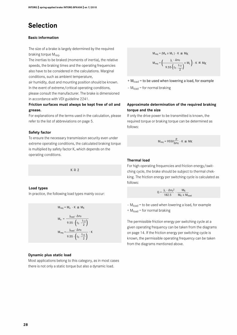
+ Mload = to be used when lowering a load, for example
– Mload = for normal braking
Selection
Basic information
The size of a brake is largely determined by the required braking torque Mreq.The inertias to be braked (moments of inertia), the relative speeds, the braking times and the operating frequencies also have to be considered in the calculations. Marginal conditions, such as ambient temperature, air humidity, dust and mounting position should be known. In the event of extreme/critical operating conditions, please consult the manufacturer. The brake is dimensioned in accordance with VDI guideline 2241.Friction surfaces must always be kept free of oil and grease. For explanations of the terms used in the calculation, please refer to the list of abbreviations on page 5.
Safety factorTo ensure the necessary transmission security even under extreme operating conditions, the calculated braking torque is multiplied by safety factor K, which depends on the operating conditions.
Load typesIn practice, the following load types mainly occur:
Mreq = Ma · K ( MK
Mreq = (Ma ± ML ) · K ( MK
Mreq = JL
· ∆n0 ± ML · K ( MK
9.55 · t3 -
t12
( 2
)
Dynamic plus static loadMost applications belong to this category, as in most cases there is not only a static torque but also a dynamic load.
Mreq
= 9550
P · K ( MK ∆n0
Approximate determination of the required braking torque and the sizeIf only the drive power to be transmitted is known, the required torque or braking torque can be determined as follows:
Thermal loadFor high operating frequencies and friction energy/swit-ching cycle, the brake should be subject to thermal chek-king. The friction energy per switching cycle is calculated as follows:
– Mload = to be used when lowering a load, for example+ Mload = for normal braking
The permissible friction energy per switching cycle at a given operating frequency can be taken from the diagrams on page 14. If the friction energy per switching cycle is known, the permissible operating frequency can be taken from the diagrams mentioned above.
K 8 2
Q = JL · ∆n02
· MK
Mreq = · Kt3 –
t12
2
· ∆n0Jload
( )9.55 ·
Ma = t3 –
t12
2
· ∆n0Jload
( )9.55 ·
182.5 MK ± Mload
( )
��
INTORQ I spring-applied brake INTORQ BFK458 I en 7/�010
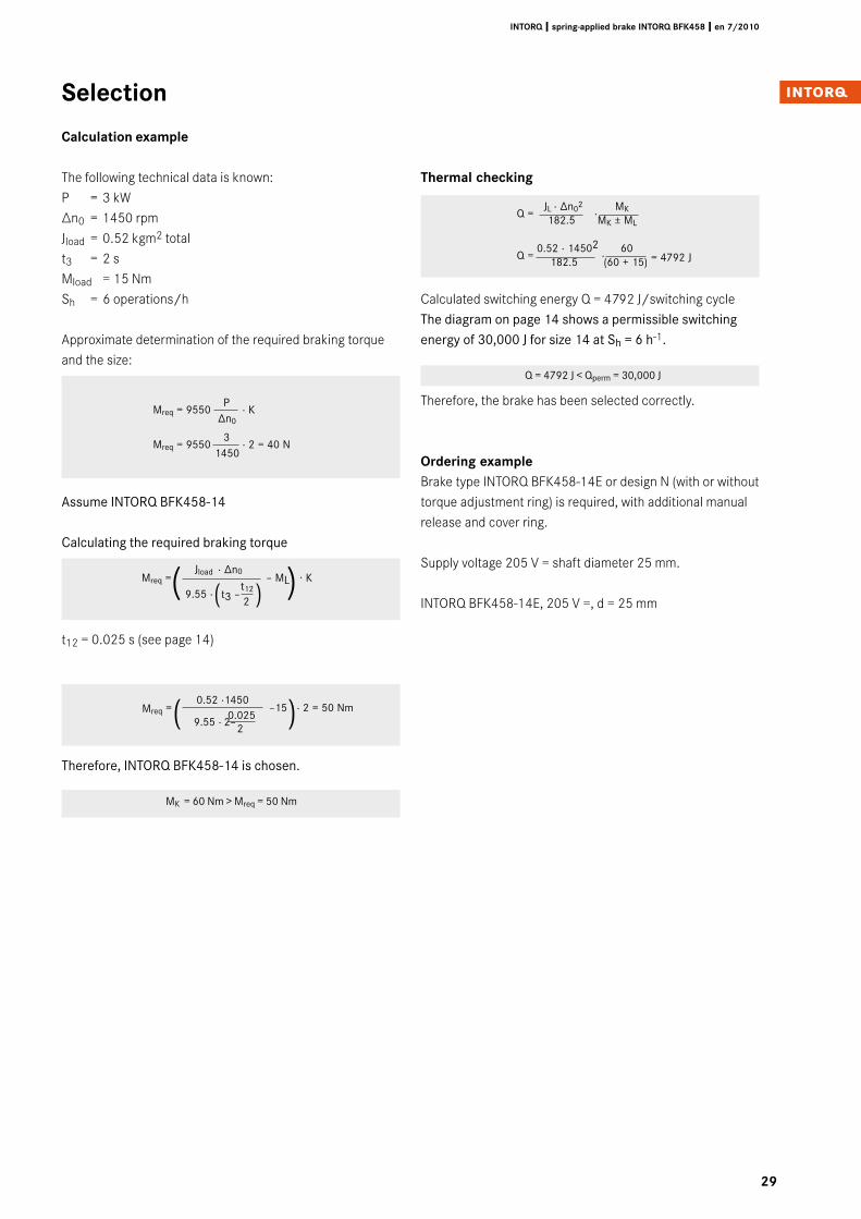
Mreq = –15 · 2 = 50 Nm
Selection
Calculation example
The following technical data is known:P = 3 kW∆n0 = 1450 rpmJload = 0.52 kgm2 totalt3 = 2 sMload = 15 NmSh = 6 operations/h
Approximate determination of the required braking torque and the size:
Mreq = 9550 P
· K ∆n0
Mreq = 9550 3
· 2 = 40 N 1450
Assume INTORQ BFK458-14
Calculating the required braking torque
t12 = 0.025 s (see page 14)
Therefore, INTORQ BFK458-14 is chosen.
MK = 60 Nm > Mreq = 50 Nm
( )
Thermal checking
Calculated switching energy Q = 4792 J/switching cycleThe diagram on page 14 shows a permissible switching energy of 30,000 J for size 14 at Sh = 6 h-1.
Q = 4792 J < Qperm = 30,000 J
Therefore, the brake has been selected correctly.
Ordering exampleBrake type INTORQ BFK458-14E or design N (with or without torque adjustment ring) is required, with additional manual release and cover ring.
Supply voltage 205 V = shaft diameter 25 mm.
INTORQ BFK458-14E, 205 V =, d = 25 mm
Q = 0.52 · 14502
· 60
182.5 (60 + 15)
0.52 ·1450
9.55 · 2–0.025
2
Q = JL · ∆n02
· MK
182.5 MK ± ML
= 4792 J
( )Mreq = – ML
t3 –t12
2
· ∆n0Jload
( )9.55 ·
· K
�0
INTORQ I spring-applied brake INTORQ BFK458 I en 7/�010
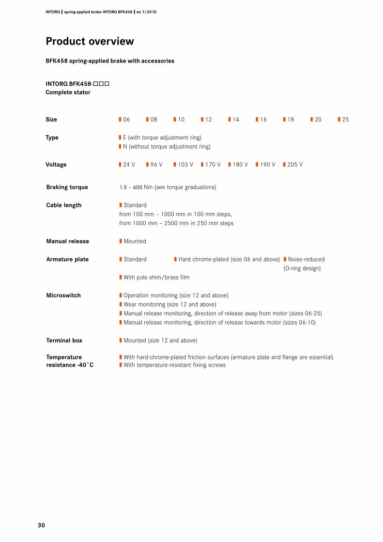
Braking torque 1.5 – 600 Nm (see torque graduations)
Cable length | Standard from 100 mm – 1000 mm in 100 mm steps, from 1000 mm – 2500 mm in 250 mm steps
Manual release | Mounted
Armature plate | Standard | Hard chrome-plated (size 06 and above) | Noise-reduced (O-ring design) | With pole shim/brass film
Microswitch | Operation monitoring (size 12 and above) | Wear monitoring (size 12 and above) | Manual release monitoring, direction of release away from motor (sizes 06-25) | Manual release monitoring, direction of release towards motor (sizes 06-10)
Terminal box | Mounted (size 12 and above)
Temperature | With hard-chrome-plated friction surfaces (armature plate and flange are essential)resistance -40˚C | With temperature-resistant fixing screws
INTORQ BFK458-òòòComplete stator
Size | 06 | 08 | 10 | 12 | 14 | 16 | 18 | 20 | 25
Type | E (with torque adjustment ring) | N (without torque adjustment ring)
Voltage | 24 V | 96 V | 103 V | 170 V | 180 V | 190 V | 205 V
Product overview
BFK458 spring-applied brake with accessories
�1
INTORQ I spring-applied brake INTORQ BFK458 I en 7/�010
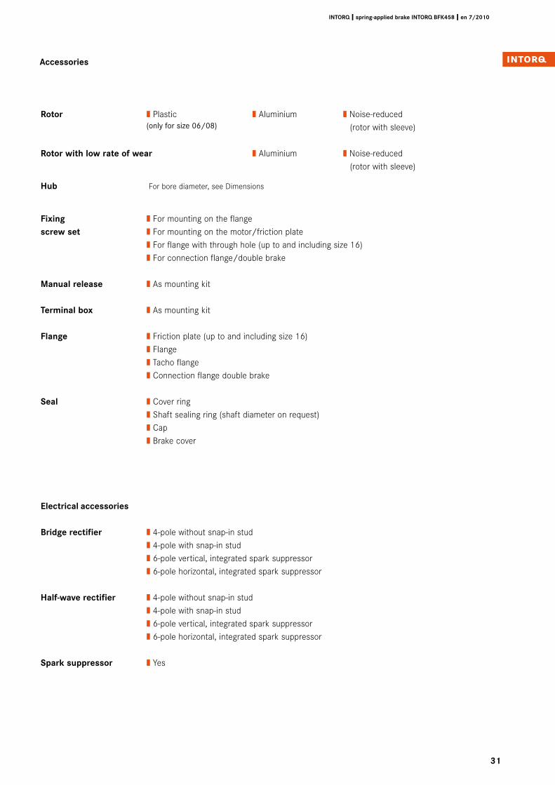
Accessories
Rotor | Plastic | Aluminium | Noise-reduced (only for size 06/08) (rotor with sleeve)
Rotor with low rate of wear | Aluminium | Noise-reduced (rotor with sleeve)
Hub For bore diameter, see Dimensions
Fixing | For mounting on the flangescrew set | For mounting on the motor/friction plate | For flange with through hole (up to and including size 16) | For connection flange/double brake
Manual release | As mounting kit
Terminal box | As mounting kit
Flange | Friction plate (up to and including size 16) | Flange | Tacho flange | Connection flange double brake
Seal | Cover ring | Shaft sealing ring (shaft diameter on request) | Cap | Brake cover
Electrical accessories
Bridge rectifier | 4-pole without snap-in stud | 4-pole with snap-in stud | 6-pole vertical, integrated spark suppressor | 6-pole horizontal, integrated spark suppressor
Half-wave rectifier | 4-pole without snap-in stud | 4-pole with snap-in stud | 6-pole vertical, integrated spark suppressor | 6-pole horizontal, integrated spark suppressor
Spark suppressor | Yes

setting the standard
www.intorq.de
1��4
���7
Su
bjec
t to
tec
hnic
al a
ltera
tions
❚ Pr
inte
d in
Ger
man
y 7/
2010
en
❚ 5 4
3 2
1 INTORQ GmbH & Co. KG
PO Box 1103D-31849 Aerzen, Germany
Wülmser Weg 5D-31855 Aerzen
Tel.: +49 (0)5154 9539-01Fax: +49 (0)5154 9539-10E-mail: [email protected]
INTORQ customers can reach us atany time and from anywhere in theworld. Our Key Account Sales Teamlooks after key account customersand project business.
In addition, we co-operate withLenze‘s global sales organisation.You can contact us via Lenze Serviceby calling the 24-hour helpline(008000 24 46177).
INTORQ –
Sales and Service
around the world


![BFK458 spring-applied brake - Lenze Selection · 2020. 12. 14. · 6I7 INTORQ I BFK458 spring-applied brake A powerful and complete range 9 sizes Standard voltages [V DC] 24, 96,](https://img.pdfslide.net/doc/110x75/6145f4848f9ff812541ff53e/bfk458-spring-applied-brake-lenze-selection-2020-12-14-6i7-intorq-i-bfk458.jpg)


![INTORQ BFK458 Spring-applied brake · 2015. 7. 22. · 1 [s] Engagement time, t 1 = t 11 + t 12 t 2 [s] Disengagement time (time from the beginning of the torque reduction until 0.1](https://img.pdfslide.net/doc/110x75/60ec2a6a0c631d665a65ea6b/intorq-bfk458-spring-applied-brake-2015-7-22-1-s-engagement-time-t-1-t.jpg)