Embed Size (px)
Citation preview
1
Springs
Chapter 19
Material from Mott, 2003, Mechanical Design of Machine Elements
SpringsA spring is a flexible element used to exert a force or a torque and, at the same time, to store energy.The force can be a linear push or pull, or it can be radial, acting similarly to a rubber band around a roll of drawings.The torque can be used to cause a rotation, for example, to close a door on a cabinet or to provide a counterbalance force for a machine element pivoting on a hinge.
Mott, 2003, Mechanical Design of Machine Elements
2
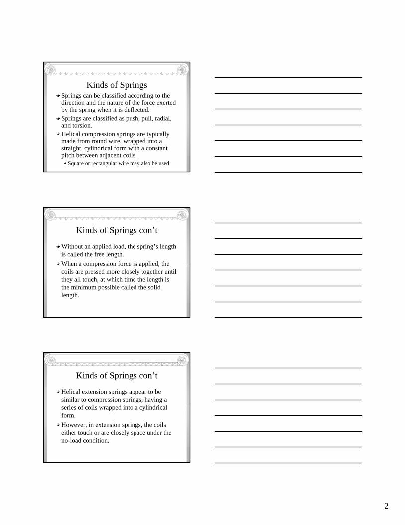
Kinds of SpringsSprings can be classified according to the direction and the nature of the force exerted by the spring when it is deflected.Springs are classified as push, pull, radial, and torsion.Helical compression springs are typically made from round wire, wrapped into a straight, cylindrical form with a constant pitch between adjacent coils.
Square or rectangular wire may also be used
Kinds of Springs con’t
Without an applied load, the spring’s length is called the free length.When a compression force is applied, the coils are pressed more closely together until they all touch, at which time the length is the minimum possible called the solid length.
Kinds of Springs con’t
Helical extension springs appear to be similar to compression springs, having a series of coils wrapped into a cylindrical form.However, in extension springs, the coils either touch or are closely space under the no-load condition.
3
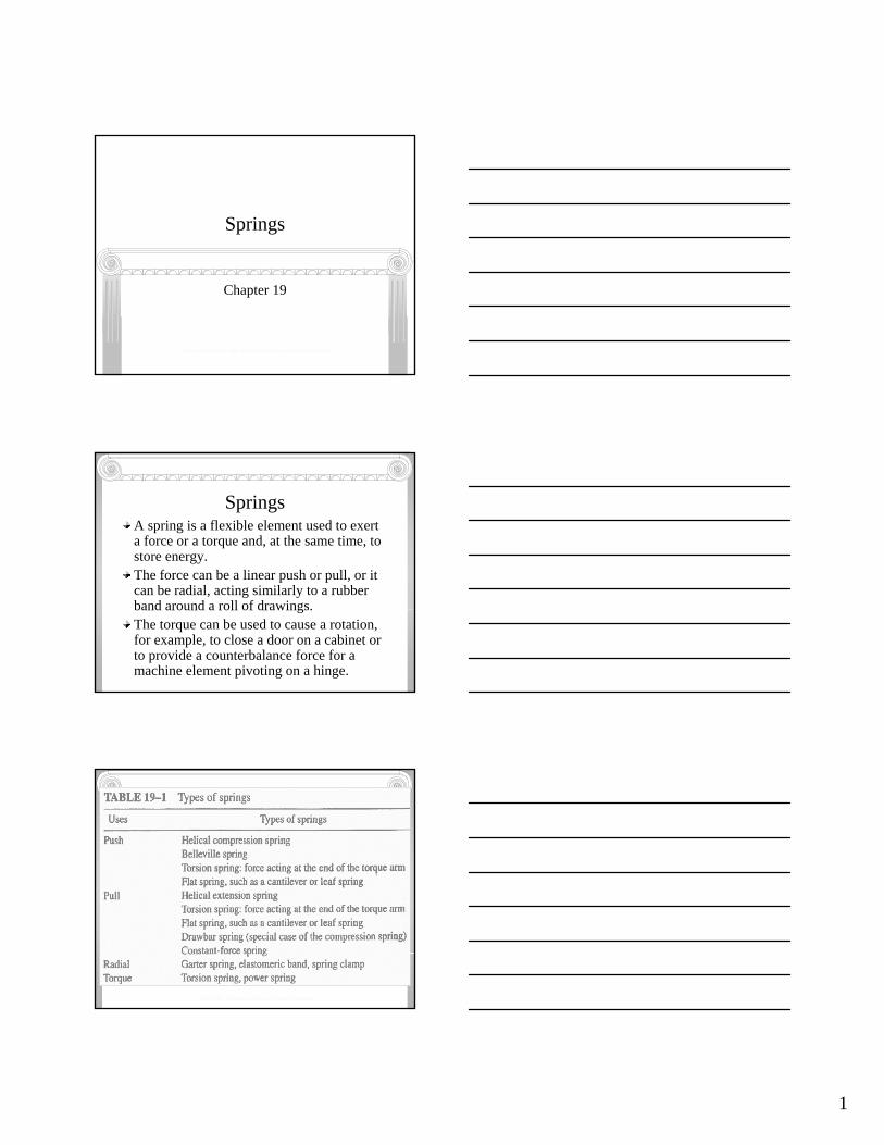
Types of Springs
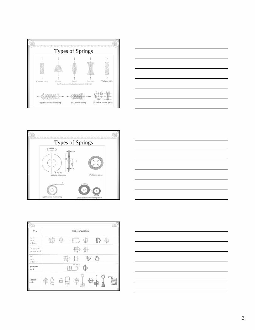
Types of Springs
4
Kinds of Springs con’t
The drawbar spring incorporates a standard helical compression spring with two looped wire devices inserted through the inside of the spring.With such a design, a tensile force can be exerted by pulling on the loops while still placing the spring in compression.
Kinds of Springs con’tA torsion string is used to exert a torque as the spring is deflected by rotation about its axis.The common spring-action clothespin uses a torsion spring to provide the gripping action.Leaf springs are made from one or more flat strips of brass, bronze, steel, or other materials loaded as cantilevers or simple beams.They can provide a push or pull force as they are deflected from their free condition.Large forces can be exerted within a small space by leaf springs.
Kinds of Springs con’tA Belleville spring has the shape of a shallow, conical disk with a central hole. It is sometimes called a Belleville washer because its appearance is similar to that of a flat washer.A very high spring rate or spring force can be developed in a small axial space with such springs.By varying the height of the cone relative to the thickness of the disk, the designer can obtain a variety of load-deflection characteristics.
5
Kinds of Springs con’t
Garter springs are coiled wire formed into a continuous ring shape so that they exert a radial force around the periphery of the object to which they are applied.Either inward or outward forces can be obtained with different designs.
Kinds of Springs con’tConstant-force springs take the form of a coiled strip.The force required to pull the strip off the coil is virtually constant over a long length of pull.The magnitude of the force is dependent on the width, thickness, and radius of curvature of the coil and on the elastic modulus of the spring material.
Helical Compression Springs
In the most common form of helical compression spring, round wire is wrapped into a cylindrical form with a constant pitch between adjacent coils.This basic form is completed by a variety of end treatments.
6
Helical Compression Springs
There are many uses of helical compression springs.The retractable ballpoint pen depends on the helical compression spring, usually installed around the ink supply barrel.Suspension systems for cars, trucks, and motorcycles frequently incorporate these springs.
Diameters
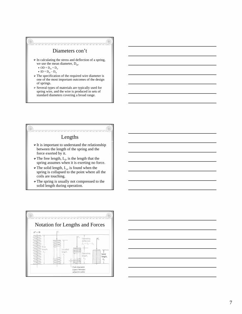
The next figure shows the notation used in referring to the characteristic diameters of helical compression springs.The outside diameter (OD), the inside diameter (ID), and the wire diameter (Dw) are obvious and can be measured with standard measuring instruments.
Mott, 2003, Mechanical Design of Machine Elements
7
Diameters con’tIn calculating the stress and deflection of a spring, we use the mean diameter, Dm.
OD = Dm + DwID = Dm – Dw
The specification of the required wire diameter is one of the most important outcomes of the design of springs.Several types of materials are typically used for spring wire, and the wire is produced in sets of standard diameters covering a broad range.
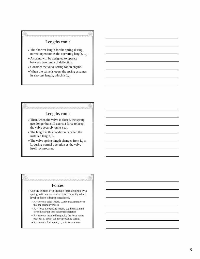
LengthsIt is important to understand the relationship between the length of the spring and the force exerted by it.The free length, Lf, is the length that the spring assumes when it is exerting no force.The solid length, Ls, is found when the spring is collapsed to the point where all the coils are touching.The spring is usually not compressed to the solid length during operation.
Notation for Lengths and Forces
Mott, 2003, Mechanical Design of Machine Elements
8
Lengths con’t
The shortest length for the spring during normal operation is the operating length, Lo.A spring will be designed to operate between two limits of deflection.Consider the valve spring for an engine.When the valve is open, the spring assumes its shortest length, which is Lo.
Lengths con’tThen, when the valve is closed, the spring gets longer but still exerts a force to keep the valve securely on its seat.The length at this condition is called the installed length, Li.The valve spring length changes from Lo to Li during normal operation as the valve itself reciprocates.
ForcesUse the symbol F to indicate forces exerted by a spring, with various subscripts to specify which level of force is being considered.
Fs = force at solid length, Ls; the maximum force that the spring ever seesFo = force at operating length, Lo; the maximum force the spring sees in normal operationFi = force at installed length, Li; the force varies between Fo and Fi for a reciprocating springFf = force at free length, Lf; this force is zero
9
Spring RateThe relationship between the force exerted by a spring and its deflection is called its spring rate, k.Any change in force divided by the corresponding change in deflection can be used to compute the spring rate:
k = ∆F / ∆Lk = (Fo – Fi) / (Li – Lo)
If the spring rate is known, the force at any deflection can be computed.
Spring IndexThe ratio of the mean diameter of the spring to the wire diameter is called the spring index, C:
C = Dm / Dw
It is recommended that C be greater than 5.0, with typical machinery springs having C values ranging from 5 to 12.For C less than 5, the forming of the spring will be difficult and the severe deformation required may create cracks in the wire.
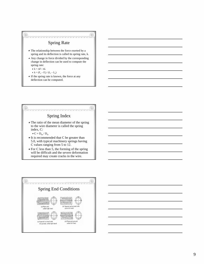
Spring End Conditions
Mott, 2003, Mechanical Design of Machine Elements
10
Number of CoilsThe total number of coils in a spring will be called N.But in the calculation of stress and deflections for a spring, some of the coils are inactive and are neglected.For example, in a spring with squared and ground ends or simply squared ends, end coils are inactive, and the number of active coils, Na, is N -2.For plain ends, all coils are active: Na = N.For plain coils with ground ends, Na = N – 1.
PitchPitch, p, refers to the axial distance for a point on one coil to the corresponding point on the next adjacent coil.The relationships among the pitch, free length, wire diameter, and number of active coils are:
Squared and ground ends: Lf = pNa + 2DwSquared ends only: Lf = pNa + 3DwPlain and ground ends: Lf = p(Na + 1)Plain ends: Lf = pNa + Dw
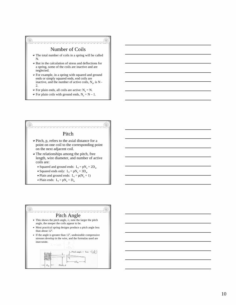
Pitch AngleThis shows the pitch angle, λ; note the larger the pitch angle, the steeper the coils appear to be.Most practical spring designs produce a pitch angle less than about 12o.If the angle is greater than 12o, undesirable compressive stresses develop in the wire, and the formulas used are inaccurate.
⎥⎦⎤
⎢⎣⎡π
=λ −
mDp1tan
11
Installation ConsiderationsFrequently, a spring is installed in a cylindrical hole or around a rod.When it is, adequate clearances must be provided.When a compression spring is compressed, its diameter gets larger.The inside diameter of a hole enclosing the spring must be greater than the outside diameter of the spring to eliminate rubbing.
Installation Considerations con’tAn initial diametral clearance of 1/10th of the wire diameter is recommended for springs having a diameter of 0.50 in (12mm) or greater.If a more precise estimate of the actual outside diameter of the spring is required, this can be used for the OD at the solid length condition:
ww
ms DDpDOD +π−
+=2
222
Installation Considerations con’t
Even though the spring ID gets larger, it is also recommended that the clearance at the ID be approximately 0.1Dw.
12
Coil ClearanceThe term coil clearance refers to the space between adjacent coils when the spring is compressed to its operating length, Lo.The actual coil clearance, cc, can be estimated from:
cc = (Lo – Ls) / Na
Our guideline is that the coil clearance should be greater than Dw / 10, especially in springs loaded cyclically.Another recommendation relates to the overall deflection of the spring:
(Lo – Ls) > 0.15 (Lf – Ls)
Stresses and DeflectionAs a compressive spring is compressed under an axial load, the wire is twisted.Therefore, the stress developed in the wire is torsional shear stress, and it can be derived from the classical equation τ = Tc / J.When the equation is applied specifically to a helical compression spring, some modifying factors are needed to account for the curvature of the spring wire and for the direct shear stress created as the coils resist the vertical load.
Stresses and Deflection
The resulting equation for stress is attributed to Wahl.The maximum shear stress, which occurs at the inner surface of the wire, is:
2388
ww
m
DKFC
DKFD
π=
π=τ
13
Mott, 2003, Mechanical Design of Machine Elements
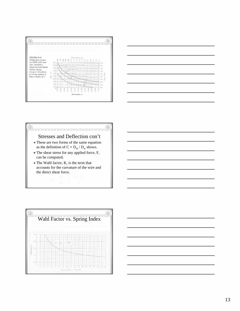
•The design shear stress in the compression spring can beobtained from figures such as the one shown below.
Stresses and Deflection con’tThese are two forms of the same equation as the definition of C = Dm / Dw shows.The shear stress for any applied force, F, can be computed.The Wahl factor, K, is the term that accounts for the curvature of the wire and the direct shear force.
CCCK 615.0
4414+
−−
=
Wahl Factor vs. Spring IndexThis shows a plot of K versus C for round wire. Recall that C = 5 is the recommended minimum value of C. The value ofK rises rapidly for C < 5.
Mott, 2003, Mechanical Design of Machine Elements
14
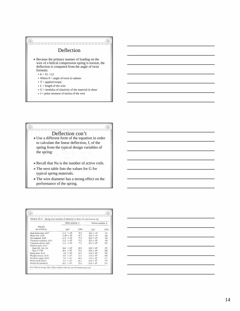
DeflectionBecause the primary manner of loading on the wire of a helical compression spring is torsion, the deflection is computed from the angle of twist formula:
θ = TL / GJWhere θ = angle of twist in radiansT = applied torqueL = length of the wireG = modulus of elasticity of the material in shearJ = polar moment of inertia of the wire
Deflection con’tUse a different form of the equation in order to calculate the linear deflection, f, of the spring from the typical design variables of the spring:
Recall that Na is the number of active coils.The next table lists the values for G for typical spring materials.The wire diameter has a strong effect on the performance of the spring.
w
a
w
am
GDNFC
GDNFDf
3
4
3 88==
Mott, 2003, Mechanical Design of Machine Elements
15
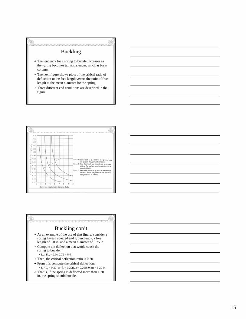
BucklingThe tendency for a spring to buckle increases as the spring becomes tall and slender, much as for a column.The next figure shows plots of the critical ratio of deflection to the free length versus the ratio of free length to the mean diameter for the spring.Three different end conditions are described in the figure.
Mott, 2003, Mechanical Design of Machine Elements
Buckling con’tAs an example of the use of that figure, consider a spring having squared and ground ends, a free length of 6.0 in, and a mean diameter of 0.75 in.Compute the deflection that would cause the spring to buckle:
Lf / Dm = 6.0 / 0.75 = 8.0Then, the critical deflection ratio is 0.20. From this compute the critical deflection:
fo / Lf = 0.20 or fo = 0.20(Lf) = 0.20(6.0 in) = 1.20 inThat is, if the spring is deflected more than 1.20 in, the spring should buckle.
16
Analysis
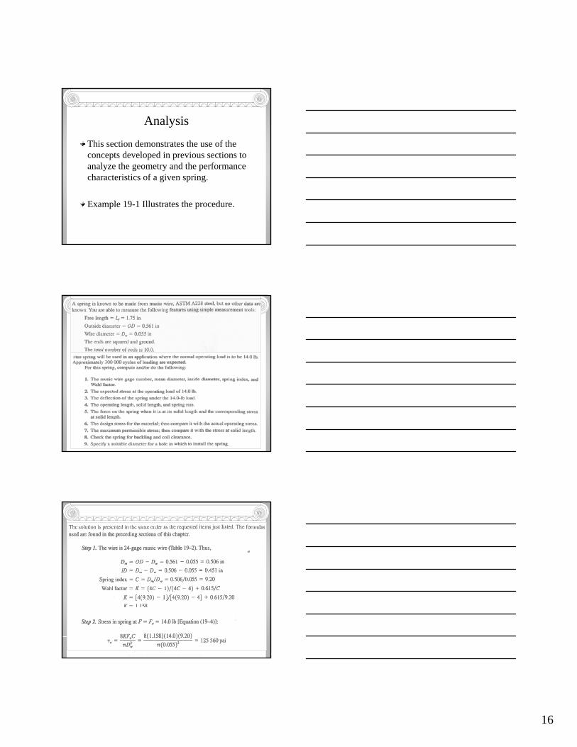
This section demonstrates the use of the concepts developed in previous sections to analyze the geometry and the performance characteristics of a given spring.
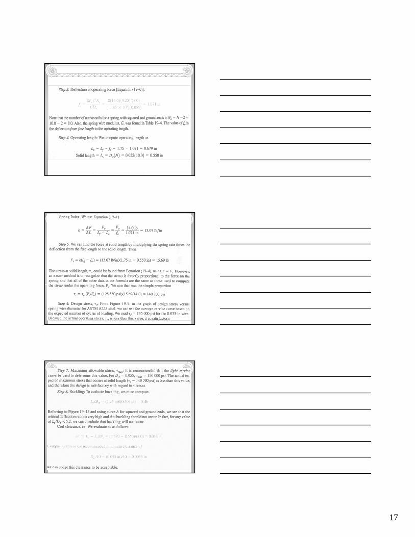
Example 19-1 Illustrates the procedure.
Mott, 2003, Mechanical Design of Machine Elements
17
Mott, 2003, Mechanical Design of Machine Elements
Mott, 2003, Mechanical Design of Machine Elements
Mott, 2003, Mechanical Design of Machine Elements
18
Mott, 2003, Mechanical Design of Machine Elements
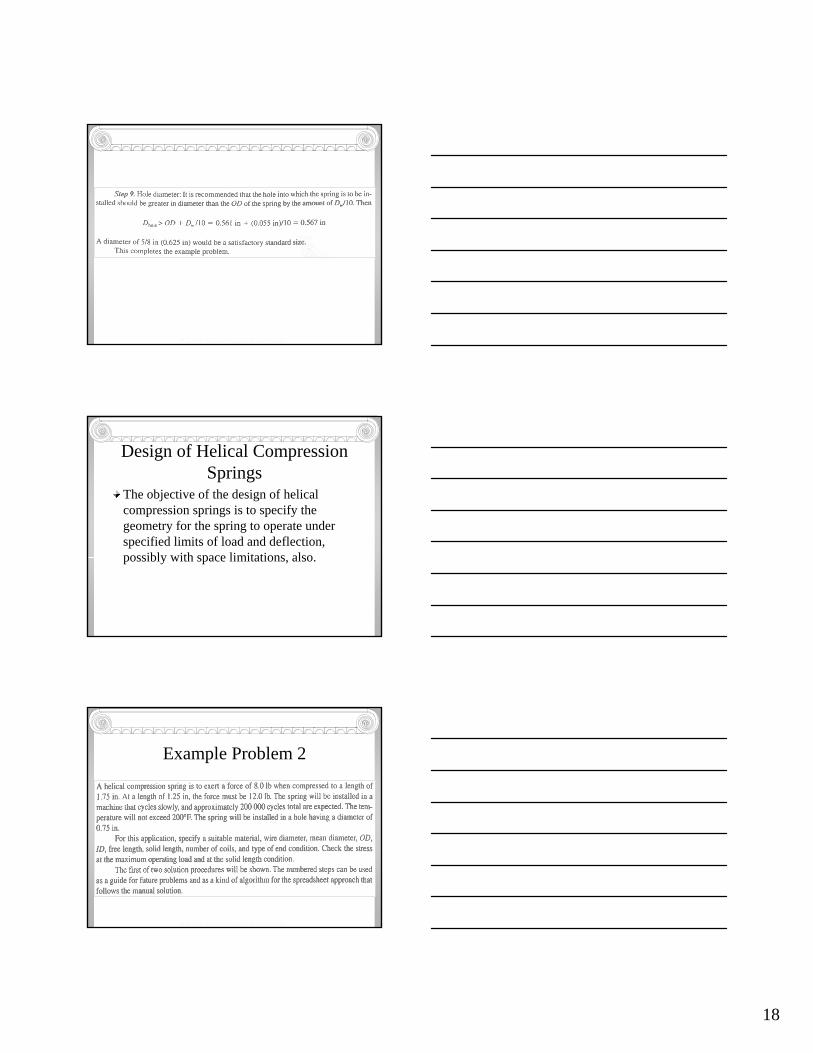
Design of Helical Compression Springs
The objective of the design of helical compression springs is to specify the geometry for the spring to operate under specified limits of load and deflection, possibly with space limitations, also.
Example Problem 2
Mott, 2003, Mechanical Design of Machine Elements
19
Mott, 2003, Mechanical Design of Machine Elements
Mott, 2003, Mechanical Design of Machine Elements
Mott, 2003, Mechanical Design of Machine Elements
20
Mott, 2003, Mechanical Design of Machine Elements
Mott, 2003, Mechanical Design of Machine Elements
Mott, 2003, Mechanical Design of Machine Elements
21
Mott, 2003, Mechanical Design of Machine Elements
Mott, 2003, Mechanical Design of Machine Elements
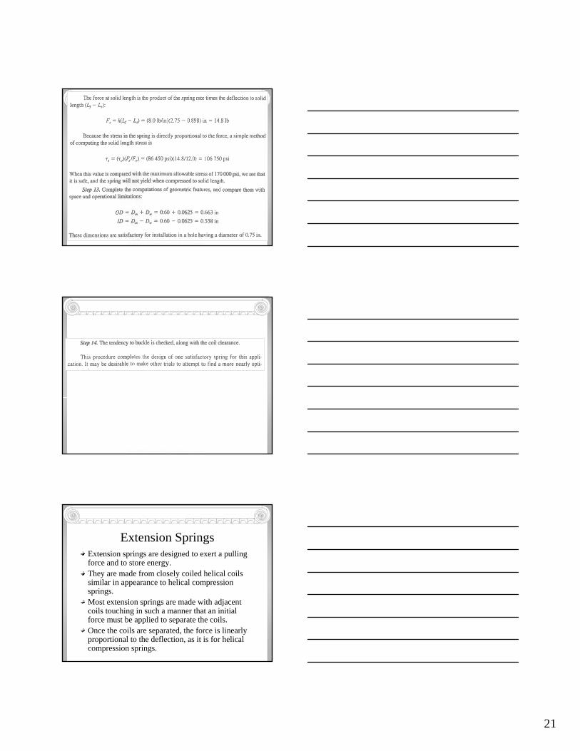
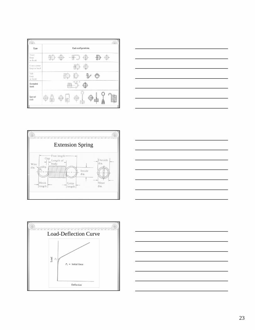
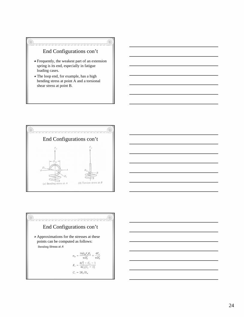
Extension SpringsExtension springs are designed to exert a pulling force and to store energy.They are made from closely coiled helical coils similar in appearance to helical compression springs.Most extension springs are made with adjacent coils touching in such a manner that an initial force must be applied to separate the coils.Once the coils are separated, the force is linearly proportional to the deflection, as it is for helical compression springs.
22
Extension Springs con’t
The stresses and deflections for an extension spring can be computed by using the formulas used for compression springs.
is used for the torsional sshear stress, for the Wahl factor to account for the curvature of the wire and the direct shear stress, andfor the deflection characteristics.
2388
ww
m
DKFC
DKFD
π=
π=τ
CCCK 615.0
4414+
−−
=
w
a
w
am
GDNFC
GDNFDf
3
4
3 88==
Extension Springs con’t
All coils in an extension spring are active.In addition, since the end loops or hooks deflect, their deflection may affect the actual spring rate.The initial tension in an extension spring is typically 10% to 25% of the maximum design force.
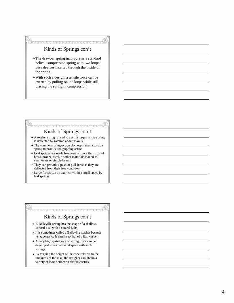
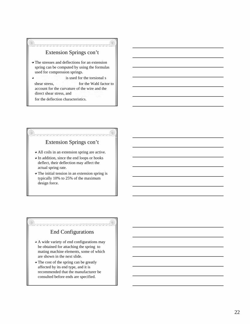
End Configurations
A wide variety of end configurations may be obtained for attaching the spring to mating machine elements, some of which are shown in the next slide.The cost of the spring can be greatly affected by its end type, and it is recommended that the manufacturer be consulted before ends are specified.
23
Mott, 2003, Mechanical Design of Machine Elements
Extension Spring
Mott, 2003, Mechanical Design of Machine Elements
Load-Deflection Curve
Mott, 2003, Mechanical Design of Machine Elements
24
End Configurations con’t
Frequently, the weakest part of an extension spring is its end, especially in fatigue loading cases.The loop end, for example, has a high bending stress at point A and a torsional shear stress at point B.
End Configurations con’t
Mott, 2003, Mechanical Design of Machine Elements
End Configurations con’t
Approximations for the stresses at these points can be computed as follows:
Mott, 2003, Mechanical Design of Machine Elements
25
End Configurations con’t
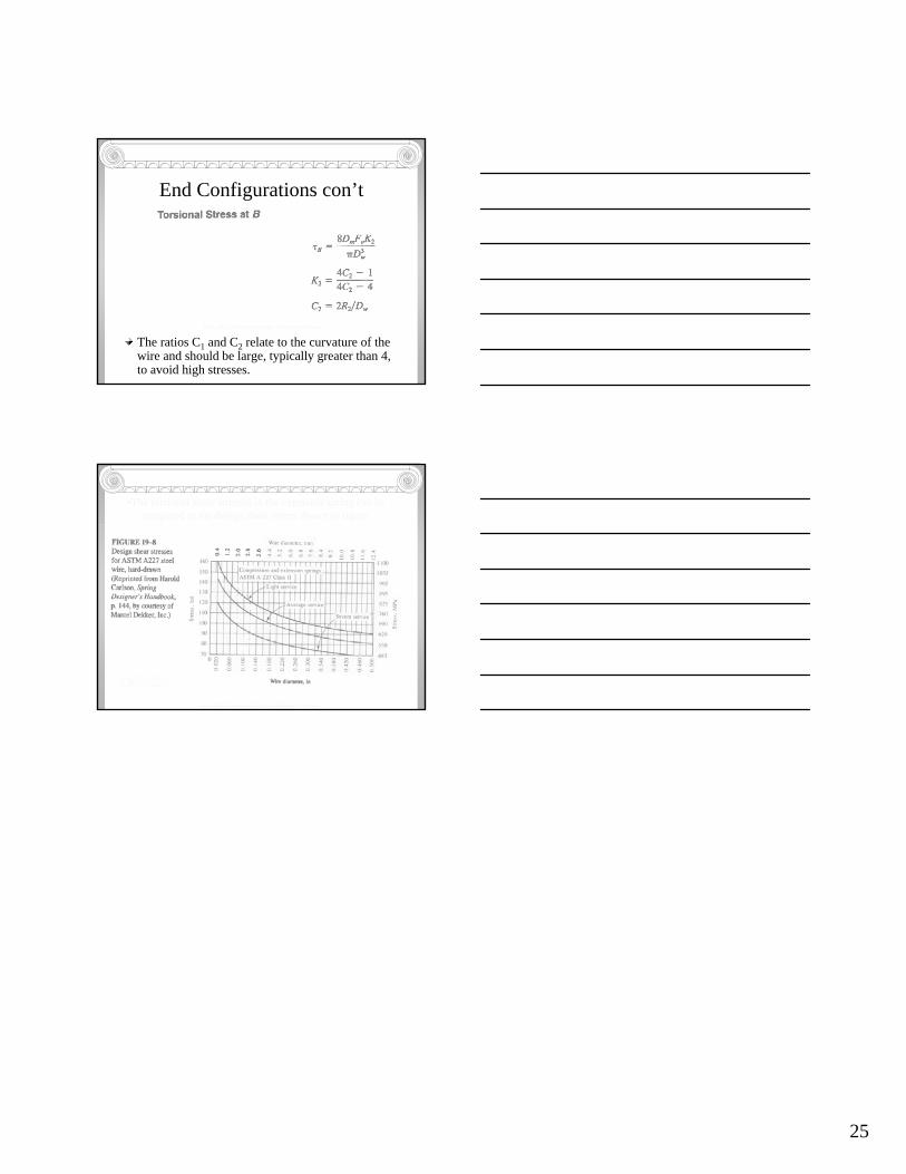
The ratios C1 and C2 relate to the curvature of the wire and should be large, typically greater than 4, to avoid high stresses.
Mott, 2003, Mechanical Design of Machine Elements
Mott, 2003, Mechanical Design of Machine Elements
•The torsional shear stresses in the extension spring can becompared to the design shear stress shown in figure.