Embed Size (px)
DESCRIPTION
Connectivity Guide
Citation preview
EMC CorporationCorporate Headquarters:
EMC® Symmetrix RemoteData Facility (SRDF®)
Connectivity GuideP/N 300-003-885
REV A08
Hopkinton, MA 01748-9103
1-508-435-1000www.EMC.com

2
Copyright © 2006–2011 EMC Corporation. All rights reserved.
Published June, 2011
EMC believes the information in this publication is accurate as of its publication date. The information is subject to change without notice.
THE INFORMATION IN THIS PUBLICATION IS PROVIDED “AS IS.” EMC CORPORATION MAKES NO REPRESENTATIONS OR WARRANTIES OF ANY KIND WITH RESPECT TO THE INFORMATION IN THIS PUBLICATION, AND SPECIFICALLY DISCLAIMS IMPLIED WARRANTIES OF MERCHANTABILITY OR FITNESS FOR A PARTICULAR PURPOSE.
Use, copying, and distribution of any EMC software described in this publication requires an applicable software license.
For the most up-to-date listing of EMC product names, see EMC Corporation Trademarks on EMC.com.
All other trademarks used herein are the property of their respective owners.
EMC Symmetrix Remote Data Facility (SRDF) Connectivity Guide
Contents
Preface.............................................................................................................................. 9
Chapter 1 SRDF Overview and ArchitectureSRDF overview.................................................................................. 16
SRDF concepts............................................................................ 16Basic SRDF configuration ......................................................... 17SRDF interfamily connectivity................................................. 18
SRDF base family products ............................................................. 19SRDF/S........................................................................................ 19SRDF/A....................................................................................... 24SRDF/DM................................................................................... 25SRDF family options ................................................................. 27
Enginuity/Symmetrix hardware changes..................................... 28
Chapter 2 Symmetrix SRDF HardwareSymmetrix VMAX systems ............................................................. 32
Symmetrix VMAX engine ........................................................ 32Front End I/O modules ............................................................ 33
Symmetrix DMX Series systems and earlier ................................. 38SRDF director hardware ........................................................... 38SRDF director functions............................................................ 39ESCON director (RA)................................................................ 40Fibre Channel director (RF)...................................................... 41Gigabit Ethernet director (RE) on Symmetrix 8000 .............. 43Multiprotocol Channel Director on the Symmetrix DMX series ............................................................................................ 44
EMC Symmetrix Remote Data Facility (SRDF) Connectivity Guide 3
Contents
Chapter 3 SRDF Network ProtocolsGigabit Ethernet ................................................................................ 50
Generic considerations ............................................................. 50MPCD and GigE director considerations .............................. 55
Fibre Channel .................................................................................... 60Generic considerations ............................................................. 60Fibre Channel director considerations ................................... 76FCIP and iFCP............................................................................ 77FC-SONET .................................................................................. 78ISL load balancing of SRDF traffic .......................................... 79
ESCON ............................................................................................... 83FarPoint....................................................................................... 85
Chapter 4 Network Topologies and ImplementationsTransport options.............................................................................. 90
Dark fiber.................................................................................... 90IP .................................................................................................. 95
Metro and WAN implementations................................................. 97Metro (local) implementation .................................................. 97WAN extended distance implement ion................................ 98Combined Metro/WAN implementation ........................... 100
WAN optimization ......................................................................... 102Best practices, recommendations, and considerations.............. 106
SRDF over a Metro or WAN.................................................. 106SRDF/AR and adaptive copy................................................ 109SRDF/A .................................................................................... 110SRDF/Star ................................................................................ 112GigE ........................................................................................... 113Fibre Channel ........................................................................... 116ESCON/FarPoint .................................................................... 117
Appendix A Cable SpecificationsCable specifications and supported distances ........................... 120
Appendix B Bandwidth by WAN LinkBandwidth by WAN link .............................................................. 124
Glossary ....................................................................................................................... 125
EMC Symmetrix Remote Data Facility (SRDF) Connectivity Guide4
Title Page
Figures
1 Basic SRDF configurations............................................................................ 172 SRDF/S overview........................................................................................... 203 Synchronous mode......................................................................................... 214 Synchronous mode of operation .................................................................. 225 Semi-synchronous mode............................................................................... 236 SRDF adaptive copy overview..................................................................... 267 Adaptive copy disk mode timeline ............................................................. 278 Symmetrix VMAX engine ............................................................................. 329 DMX 8-port ESCON director designations ................................................ 4110 DMX 8-port Fibre Channel front-end host director designations........... 4211 Symmetrix 8000 2-port GigE remote director channel designations ..... 4312 DMX-1/2 Multiprotocol Director with FICON, iSCSI, and GigE
remote director designations (one MM and three SM ports) ....................4413 DMX-3 Multiprotocol Director with Fibre Channel, GigE, and iSCSI,
and FICON port designations ...................................................................... 4614 DMX-4 Multiprotocol Director with Fibre Channel, GigE, and iSCSI,
and FICON port designations ...................................................................... 4615 SRDF/A latency and packet loss ................................................................. 5316 SRDF / GigE in switched network .............................................................. 5517 Throughput increase with additional TCP connections example........... 5718 Software and hardware compression (Enginuity v5874 and later) ........ 5819 BB_Credit mechanism ................................................................................... 6220 BB_Credit allowing multiple frame transmission before R_RDY........... 6421 2 Gb/s on 10 km link example ..................................................................... 6522 Flow control managed by Symmetrix RF adapters (without buffering
from distance extension devices) ...................................................................6523 Flow control managed by Fibre Channel switch (without buffering
from distance extension devices) ...................................................................6624 Flow control (with buffering from distance extension devices).............. 6725 Normal write command process.................................................................. 69
EMC Symmetrix Remote Data Facility (SRDF) Connectivity Guide 5
Figures
26 SRDF SiRT ....................................................................................................... 7027 Write command with SiRT ........................................................................... 7128 All F_Ports will benefit.................................................................................. 7229 VSAN example ............................................................................................... 7530 Parallel ISL links, employing ISL load sharing example.......................... 7931 ISL traffic example ......................................................................................... 8132 SRDF ESCON topologies (Point-to-point).................................................. 8433 SRDF with and without FarPoint ................................................................ 8634 Fibre Channel storage extension over SONET/SDH ............................... 9335 VCAT ............................................................................................................... 9436 SRDF Metro configuration example............................................................ 9737 SRDF network configuration example........................................................ 9938 Concurrent SRDF/A example.................................................................... 10039 SRDF/AR Multihop example..................................................................... 10140 In-line configuration .................................................................................... 10241 Out-of-path configuration........................................................................... 10342 Metro SRDF/S DWDM connectivity options .......................................... 10743 SRDF/A cycle ............................................................................................... 11144 SRDF/Star example ..................................................................................... 113
EMC Symmetrix Remote Data Facility (SRDF) Connectivity Guide6
Title Page
Tables
1 Enginuity changes........................................................................................... 282 Fibre Channel I/O models ............................................................................. 343 iSCSI/GigE I/O models ................................................................................. 354 Fibre Channel/iSCSI/GigE options ............................................................. 355 Fibre Channel/FICON models...................................................................... 366 FICON iSCSI/GigE I/O models ................................................................... 377 Combination port assignments ..................................................................... 458 Time/Latency to distance .............................................................................. 609 BB_Credits compared to distance for a fully-utilized link........................ 6310 Cable specifications....................................................................................... 12011 Bandwidth by WAN link ............................................................................. 124
EMC Symmetrix Remote Data Facility (SRDF) Connectivity Guide 7

Tables
EMC Symmetrix Remote Data Facility (SRDF) Connectivity Guide8
Preface
As part of an effort to improve and enhance the performance and capabilities of its product line, EMC from time to time releases revisions of its hardware and software. Therefore, some functions described in this document may not be supported by all revisions of the software or hardware currently in use. For the most up-to-date information on product features, refer to your product release notes.
If a product does not function properly or does not function as described in this document, please contact your EMC representative.
EMC Symmetrix Remote Data Facility (SRDF) is the industry-leading business-continuity, information-protection, and content-replication software-controlled solution. SRDF can extend the physical fiber connections between Symmetrix systems, using telecommunication networking technology.
Note: For simplicity, this document uses the term SRDF to represent all the EMC SRDF family products.
Audience This guide is intended for use by EMC customers, partners, technical architects, field support, and customer service engineers involved with the design and deployment of SRDF networks. The audience is expected to be familiar with SRDF. More basic information on SRDF can be found in the EMC Symmetrix Remote Data Facility (SRDF) Product Guide, available at http://Powerlink.EMC.com, under Support > Technical Documentation and Advisories.
EMC Symmetrix Remote Data Facility (SRDF) Connectivity Guide 9
10
Preface
Organization This document is intended to provide the reader with a connectivity-focused guide for deploying SRDF. To accomplish this goal, this guide is structured around various building blocks needed for successful SRDF network implementations and includes the following information:
◆ General information on SRDF technology
◆ Symmetrix hardware and Enginuity information relevant to SRDF
◆ Various network protocols available for SRDF deployments
◆ Various network topologies and transports available for SRDF deployments
Various levels of technical information will be provided as well as best practices where applicable.
This guide may reference non-EMC products and technologies. It is not within the scope of this guide to go into any detail on third-party products. For more information on third-party products, refer to third-party documentation and/or the EMC Networked Storage Topology Guide available through E-Lab Interoperability Navigator at: http://elabnavigator.EMC.com.
Note: The implementations described in this document for medium-distance or long-distance solutions can be used locally as well. Proper planning will include all useful alternatives and can often benefit from existing equipment or other local considerations. Additionally, some limitations quoted in this document are subject to relatively frequent change. Contact your EMC Customer Support representative for the latest distance information before planning an implementation.
Relateddocumentation
Related documents include:
◆ EMC Networked Storage Topology Guide, available through E-Lab Interoperability Navigator at http://elabnavigator.EMC.com
◆ EMC Symmetrix Remote Data Facility (SRDF) Product Guide, available on Powerlink at http://Powerlink.EMC.com, under Support > Technical Documentation and Advisories
◆ Symmetrix product guides, available at http://Powerlink.EMC.com, under Support > Technical Documentation and Advisories
EMC Symmetrix Remote Data Facility (SRDF) Connectivity Guide
Preface
◆ Symmetrix physical planning guides, available at http://Powerlink.EMC.com, under Support > Technical Documentation and Advisories
◆ SRDF interfamily connectivity support information can be found at http://elabnavigator.EMC.com
◆ For the most up-to-date information, always consult the EMC Support Matrix (ESM), available through E-Lab Interoperability Navigator (ELN) at: http://elabnavigator.EMC.com, under the PDFs and Guides tab.
The EMC Support Matrix links within this topology guide will take you to Powerlink where you are asked to log in to the E-Lab Interoperability Navigator. Instructions on how to best use the ELN (tutorial, queries, wizards) are provided below this Log in window. If you are unfamiliar with finding information on this site, read these instructions before proceeding any further.
Under the PDFs and Guides tab resides a collection of printable resources for reference or download.
All of the matrices, including the ESM (which does not include most software), are subsets of the E-Lab Interoperability Navigator database. Included under this tab are:
• The EMC Support Matrix, a complete guide to interoperable, and supportable, configurations.
• Subset matrices for specific storage families, server families, operating systems or software product.
• Host connectivity guides for complete, authoritative information on how to configure hosts effectively for various storage environments.
Under the PDFs and Guides tab, consult the Internet Protocol pdf under the "Miscellaneous" heading for EMC's policies and requirements for the EMC Support Matrix.
For detailed information regarding solutions that involve other qualified vendors' equipment, refer to the appropriate product specification manuals available from each vendor, or ask your site representative to contact the appropriate EMC partner vendor or EMC Technical Support/Engineering.
EMC Symmetrix Remote Data Facility (SRDF) Connectivity Guide 11
12
Preface
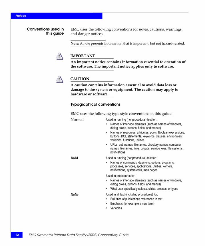
Conventions used inthis guide
EMC uses the following conventions for notes, cautions, warnings, and danger notices.
Note: A note presents information that is important, but not hazard-related.
IMPORTANT!An important notice contains information essential to operation of the software. The important notice applies only to software.
CAUTION!A caution contains information essential to avoid data loss or damage to the system or equipment. The caution may apply to hardware or software.
Typographical conventions
EMC uses the following type style conventions in this guide:
Normal Used in running (nonprocedural) text for:• Names of interface elements (such as names of windows,
dialog boxes, buttons, fields, and menus)• Names of resources, attributes, pools, Boolean expressions,
buttons, DQL statements, keywords, clauses, environment variables, functions, utilities
• URLs, pathnames, filenames, directory names, computer names, filenames, links, groups, service keys, file systems, notifications
Bold Used in running (nonprocedural) text for:• Names of commands, daemons, options, programs,
processes, services, applications, utilities, kernels, notifications, system calls, man pages
Used in procedures for:• Names of interface elements (such as names of windows,
dialog boxes, buttons, fields, and menus)• What user specifically selects, clicks, presses, or types
Italic Used in all text (including procedures) for:• Full titles of publications referenced in text• Emphasis (for example a new term)• Variables
EMC Symmetrix Remote Data Facility (SRDF) Connectivity Guide
Preface
Where to get help EMC support, product, and licensing information can be obtained as follows.
Product information — For documentation, release notes, software updates, or for information about EMC products, licensing, and service, go to the EMC Powerlink website (registration required) at:
http://Powerlink.EMC.com
Technical support — For technical support, go to EMC Customer Service on Powerlink. To open a service request through Powerlink, you must have a valid support agreement. Please contact your EMC sales representative for details about obtaining a valid support agreement or to answer any questions about your account.
Your comments Your suggestions will help us continue to improve the accuracy, organization, and overall quality of our user publications. Please send your opinion of this document to:
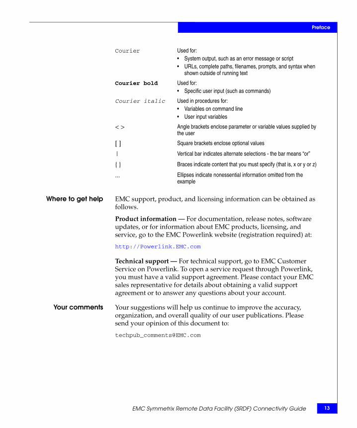
Courier Used for:• System output, such as an error message or script • URLs, complete paths, filenames, prompts, and syntax when
shown outside of running text
Courier bold Used for:• Specific user input (such as commands)
Courier italic Used in procedures for:• Variables on command line• User input variables
< > Angle brackets enclose parameter or variable values supplied by the user
[ ] Square brackets enclose optional values
| Vertical bar indicates alternate selections - the bar means “or”
{ } Braces indicate content that you must specify (that is, x or y or z)
... Ellipses indicate nonessential information omitted from the example
EMC Symmetrix Remote Data Facility (SRDF) Connectivity Guide 13

14
Preface
EMC Symmetrix Remote Data Facility (SRDF) Connectivity Guide
1Invisible Body Tag
This chapter contains the following information:
◆ SRDF overview................................................................................... 16◆ SRDF base family products .............................................................. 19◆ Enginuity/Symmetrix hardware changes...................................... 28
SRDF Overview andArchitecture
SRDF Overview and Architecture 15
16
SRDF Overview and Architecture
SRDF overviewThe EMC® Symmetrix® Remote Data Facility (SRDF®) family of remote replication software offers various levels of Symmetrix-based business continuance and disaster recovery solutions. The SRDF products offer the capability to maintain multiple copies of data, independent of this host and operating system. SRDF configurations require at least two Symmetrix systems, also known as the primary and the secondary system. Both sites can be located in the same room, in different buildings within the same campus, or hundreds to thousands of kilometers apart.
Note: For simplicity, this document uses the term SRDF to represent all EMC SRDF-related products, including: SRDF/A, SRDF/AR (multi-hop and single-hop), SRDF/DM, and SRDF/CG. Most of the document focuses on SRDF/S, but generally it applies to any of the variations.
By maintaining copies of data in different physical locations, SRDF enables you to perform the following operations with minimal impact on normal business processing:
◆ Disaster restart
◆ Disaster restart testing
◆ Recovery from planned outages
◆ Remote backup
◆ Data center migration
◆ Data replication and mobility
SRDF conceptsThe EMC Symmetrix Remote Data Facility (SRDF) Product Guide, located on Powerlink, provides detailed information on the following SRDF concepts:
◆ Symmetrix logical volumes, RAID groups, and mirrors
◆ SRDF volumes, volume states, and groups
◆ Links
EMC Symmetrix Remote Data Facility (SRDF) Connectivity Guide
SRDF Overview and Architecture
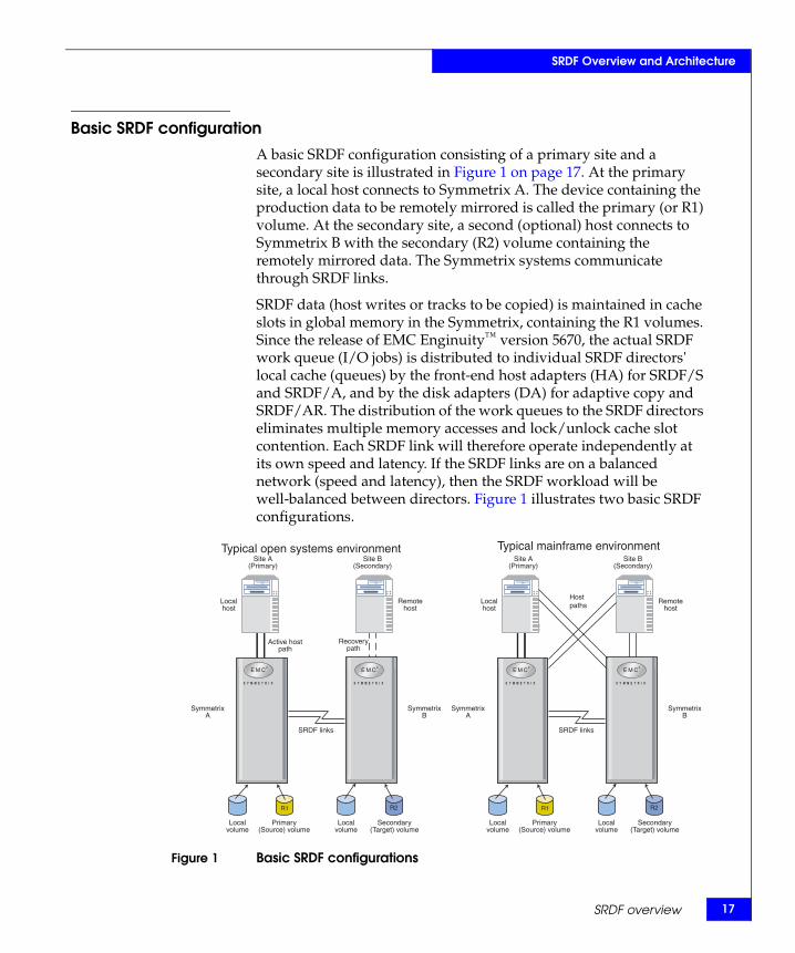
Basic SRDF configurationA basic SRDF configuration consisting of a primary site and a secondary site is illustrated in Figure 1 on page 17. At the primary site, a local host connects to Symmetrix A. The device containing the production data to be remotely mirrored is called the primary (or R1) volume. At the secondary site, a second (optional) host connects to Symmetrix B with the secondary (R2) volume containing the remotely mirrored data. The Symmetrix systems communicate through SRDF links.
SRDF data (host writes or tracks to be copied) is maintained in cache slots in global memory in the Symmetrix, containing the R1 volumes. Since the release of EMC Enginuity™ version 5670, the actual SRDF work queue (I/O jobs) is distributed to individual SRDF directors' local cache (queues) by the front-end host adapters (HA) for SRDF/S and SRDF/A, and by the disk adapters (DA) for adaptive copy and SRDF/AR. The distribution of the work queues to the SRDF directors eliminates multiple memory accesses and lock/unlock cache slot contention. Each SRDF link will therefore operate independently at its own speed and latency. If the SRDF links are on a balanced network (speed and latency), then the SRDF workload will be well-balanced between directors. Figure 1 illustrates two basic SRDF configurations.
Figure 1 Basic SRDF configurations
Site A(Primary)
Site B(Secondary)
Localhost
Remotehost
SRDF links
SymmetrixA
SymmetrixB
Localvolume
Localvolume
Primary(Source) volume
Secondary(Target) volume
R1 R2
Site A(Primary)
Site B(Secondary)
Localhost
Remotehost
SRDF links
SymmetrixA
SymmetrixB
Recoverypath
Active hostpath
Localvolume
Localvolume
Primary(Source) volume
Secondary(Target) volume
R1 R2
Typical mainframe environmentTypical open systems environment
Hostpaths
SRDF overview 17
18
SRDF Overview and Architecture
For information on typical SRDF configurations, refer to the EMC Symmetrix Remote Data Facility (SRDF) Product Guide located on Powerlink.
SRDF interfamily connectivitySRDF supports connectivity between Symmetrix models running various levels of Enginuity. Details about SRDF interfamily connectivity options are available on Powerlink.
EMC Symmetrix Remote Data Facility (SRDF) Connectivity Guide
SRDF Overview and Architecture
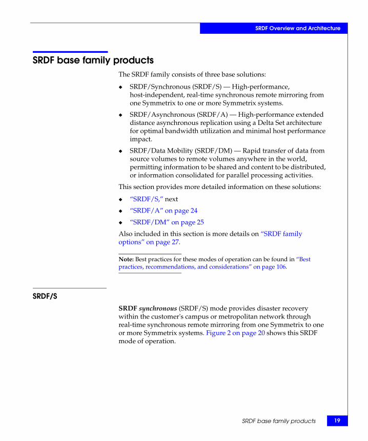
SRDF base family productsThe SRDF family consists of three base solutions:
◆ SRDF/Synchronous (SRDF/S) — High-performance, host-independent, real-time synchronous remote mirroring from one Symmetrix to one or more Symmetrix systems.
◆ SRDF/Asynchronous (SRDF/A) — High-performance extended distance asynchronous replication using a Delta Set architecture for optimal bandwidth utilization and minimal host performance impact.
◆ SRDF/Data Mobility (SRDF/DM) — Rapid transfer of data from source volumes to remote volumes anywhere in the world, permitting information to be shared and content to be distributed, or information consolidated for parallel processing activities.
This section provides more detailed information on these solutions:
◆ “SRDF/S,” next
◆ “SRDF/A” on page 24
◆ “SRDF/DM” on page 25
Also included in this section is more details on “SRDF family options” on page 27.
Note: Best practices for these modes of operation can be found in “Best practices, recommendations, and considerations” on page 106.
SRDF/SSRDF synchronous (SRDF/S) mode provides disaster recovery within the customer's campus or metropolitan network through real-time synchronous remote mirroring from one Symmetrix to one or more Symmetrix systems. Figure 2 on page 20 shows this SRDF mode of operation.
SRDF base family products 19
20
SRDF Overview and Architecture
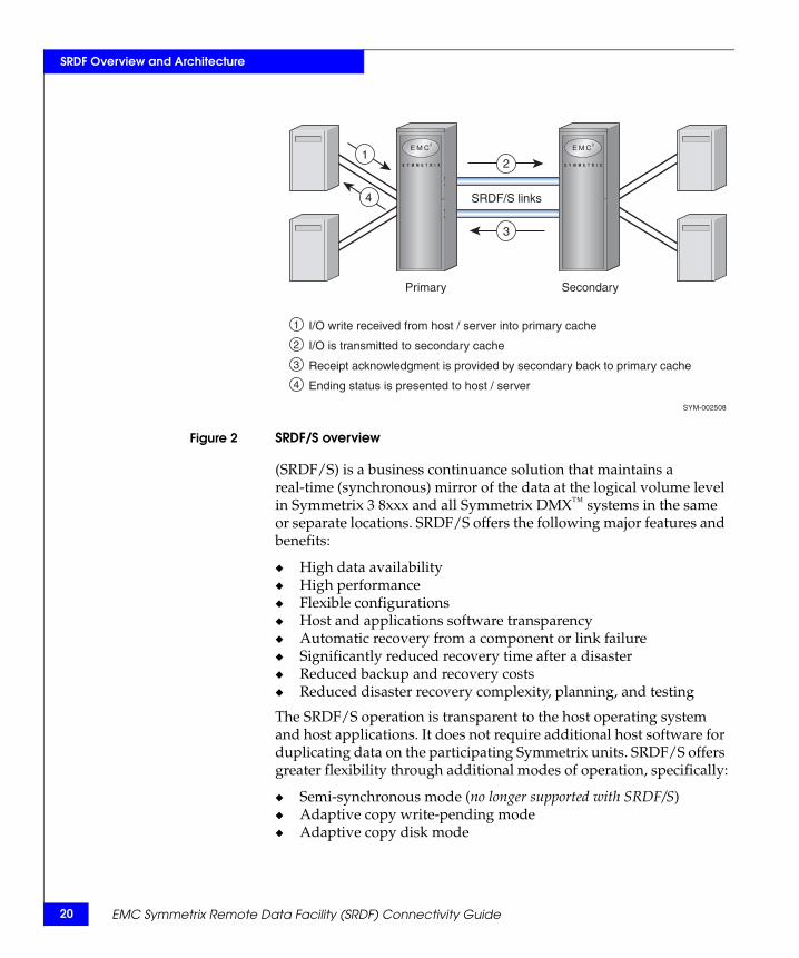
Figure 2 SRDF/S overview
(SRDF/S) is a business continuance solution that maintains a real-time (synchronous) mirror of the data at the logical volume level in Symmetrix 3 8xxx and all Symmetrix DMX™ systems in the same or separate locations. SRDF/S offers the following major features and benefits:
◆ High data availability◆ High performance◆ Flexible configurations◆ Host and applications software transparency◆ Automatic recovery from a component or link failure◆ Significantly reduced recovery time after a disaster◆ Reduced backup and recovery costs◆ Reduced disaster recovery complexity, planning, and testing
The SRDF/S operation is transparent to the host operating system and host applications. It does not require additional host software for duplicating data on the participating Symmetrix units. SRDF/S offers greater flexibility through additional modes of operation, specifically:
◆ Semi-synchronous mode (no longer supported with SRDF/S)◆ Adaptive copy write-pending mode◆ Adaptive copy disk mode
SRDF/S links
Primary Secondary
1
2
3
4
I/O write received from host / server into primary cache
I/O is transmitted to secondary cache
Receipt acknowledgment is provided by secondary back to primary cache
Ending status is presented to host / server
SYM-002508
12
3
4
EMC Symmetrix Remote Data Facility (SRDF) Connectivity Guide
SRDF Overview and Architecture
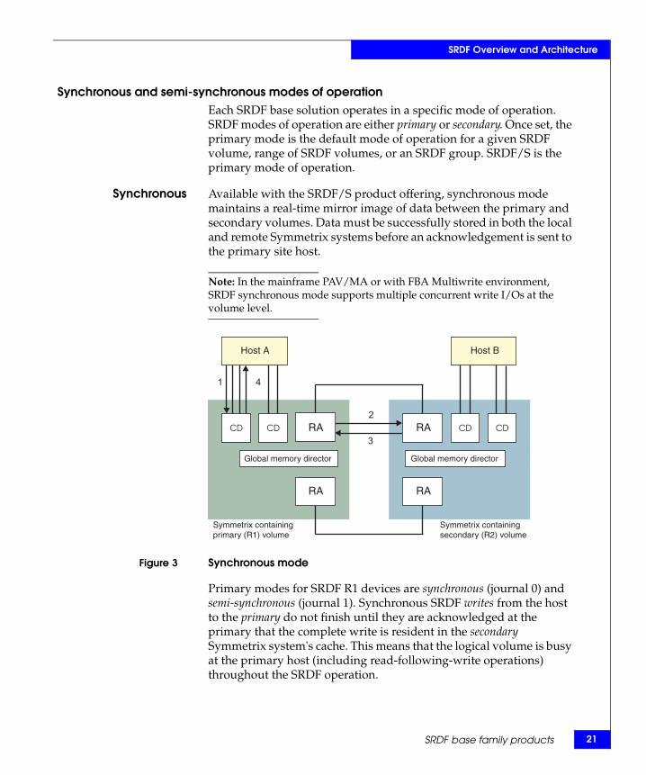
Synchronous and semi-synchronous modes of operationEach SRDF base solution operates in a specific mode of operation. SRDF modes of operation are either primary or secondary. Once set, the primary mode is the default mode of operation for a given SRDF volume, range of SRDF volumes, or an SRDF group. SRDF/S is the primary mode of operation.
Synchronous Available with the SRDF/S product offering, synchronous mode maintains a real-time mirror image of data between the primary and secondary volumes. Data must be successfully stored in both the local and remote Symmetrix systems before an acknowledgement is sent to the primary site host.
Note: In the mainframe PAV/MA or with FBA Multiwrite environment, SRDF synchronous mode supports multiple concurrent write I/Os at the volume level.
Figure 3 Synchronous mode
Primary modes for SRDF R1 devices are synchronous (journal 0) and semi-synchronous (journal 1). Synchronous SRDF writes from the host to the primary do not finish until they are acknowledged at the primary that the complete write is resident in the secondary Symmetrix system's cache. This means that the logical volume is busy at the primary host (including read-following-write operations) throughout the SRDF operation.
Host A Host B
4
3
2
1
Symmetrix containing primary (R1) volume
Symmetrix containing secondary (R2) volume
Global memory director Global memory director
RA
RA
RA
RA
SRDF base family products 21
22
SRDF Overview and Architecture
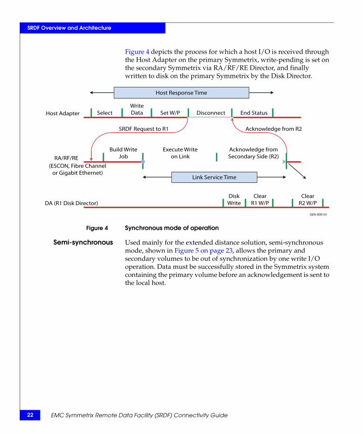
Figure 4 depicts the process for which a host I/O is received through the Host Adapter on the primary Symmetrix, write-pending is set on the secondary Symmetrix via RA/RF/RE Director, and finally written to disk on the primary Symmetrix by the Disk Director.
Figure 4 Synchronous mode of operation
Semi-synchronous Used mainly for the extended distance solution, semi-synchronous mode, shown in Figure 5 on page 23, allows the primary and secondary volumes to be out of synchronization by one write I/O operation. Data must be successfully stored in the Symmetrix system containing the primary volume before an acknowledgement is sent to the local host.
Host Adapter SelectWriteData Set W/P Disconnect End Status
Host Response Time
Link Service Time
DA (R1 Disk Director)Clear
R1 W/PClear
R2 W/PDisk
Write
RA/RF/RE(ESCON, Fibre Channel
or Gigabit Ethernet)
Build WriteJob
Execute Writeon Link
Acknowledge fromSecondary Side (R2)
SRDF Request to R1 Acknowledge from R2
GEN-000141
EMC Symmetrix Remote Data Facility (SRDF) Connectivity Guide
SRDF Overview and Architecture
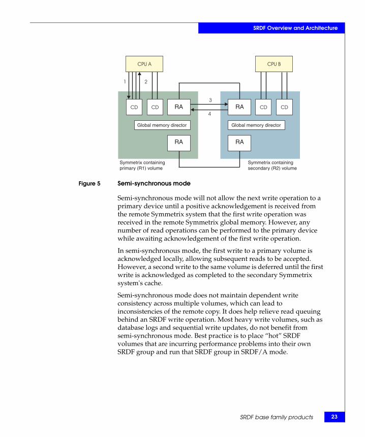
Figure 5 Semi-synchronous mode
Semi-synchronous mode will not allow the next write operation to a primary device until a positive acknowledgement is received from the remote Symmetrix system that the first write operation was received in the remote Symmetrix global memory. However, any number of read operations can be performed to the primary device while awaiting acknowledgement of the first write operation.
In semi-synchronous mode, the first write to a primary volume is acknowledged locally, allowing subsequent reads to be accepted. However, a second write to the same volume is deferred until the first write is acknowledged as completed to the secondary Symmetrix system's cache.
Semi-synchronous mode does not maintain dependent write consistency across multiple volumes, which can lead to inconsistencies of the remote copy. It does help relieve read queuing behind an SRDF write operation. Most heavy write volumes, such as database logs and sequential write updates, do not benefit from semi-synchronous mode. Best practice is to place “hot” SRDF volumes that are incurring performance problems into their own SRDF group and run that SRDF group in SRDF/A mode.
Symmetrix containing primary (R1) volume
Symmetrix containing secondary (R2) volume
Global memory director Global memory director
RA
RA
RA
RA
SRDF base family products 23
24
SRDF Overview and Architecture
Note: Semi-synchronous mode is not supported with FICON mainframe host adapters and not supported with any host adapter beginning with Symmetrix DMX-3. In the mainframe PAV/MA environment, semi-synchronous mode is not recommended because it provides no performance benefit. SRDF users seeking the increased parallelism offered by PAVs should run SRDF in synchronous mode.
SRDF/ABeginning with Enginuity version 5670, the Symmetrix DMX system supports the asynchronous replication product, SRDF/Asynchronous (SRDF/A). SRDF/A is another mode of remote replication that allows customers to asynchronously replicate data while maintaining a dependent write consistent copy of the data on the secondary (R2) device at all times. The dependant write consistent point-in time copy of the data at the secondary side is typically only seconds behind the primary (R1) side. SRDF/A session data is transferred to the secondary Symmetrix system in cycles or delta sets, eliminating the redundancy of multiple same track changes being transferred over the SRDF links, potentially reducing the required bandwidth.
SRDF/A provides a long-distance replication solution with minimal impact on performance. This level of protection is intended for customers who require minimal host application impact while maintaining a dependant write consistent, restartable image of their data at the secondary site. In the event of a disaster at the primary (R1) site or if SRDF links are lost during data transfer, a partial delta set of data can be discarded, preserving dependant write consistency on the secondary site with a data loss of no more than two SRDF/A cycles.
SRDF/A Transmit Idle SRDF/A Transmit Idle enables asynchronous replication operations to remain active in the event all links are lost temporarily due to network outages. The time SRDF/A remains active will depend on the system not reaching the system write pending limit or SRDF/A max cache limit, which is user setable.
Recent enhancements to this feature include:
◆ Allows SRDF/A to weather longer network outages during All Links Lost condition.
EMC Symmetrix Remote Data Facility (SRDF) Connectivity Guide
SRDF Overview and Architecture
◆ Allows SRDF/A to remain fully active (on primary Symmetrix) during network outages.
◆ As links return, SRDF/A will resume the Transmit delta set transfer where it left off.
◆ System requirements:
• Symmetrix must be running Enginuity version 5671 or later.• For open systems, Solutions Enabler 6.4 or later.• For mainframe systems, Host Component 5.3 or later;
Resource Pack Base 5.5 or later.• SRDF/A Transmit idle is not supported on ESCON RAs.• SRDF/A Transmit Idle needs to be enabled at both the
primary and secondary sites. This is a default feature with Enginuity version 5773.
For information on SRDF/A, refer to the EMC Symmetrix Remote Data Facility (SRDF) Product Guide located on Powerlink.
SRDF/DMSRDF/Data Mobility (SRDF/DM) is an SRDF product offering that permits operation in SRDF adaptive copy mode only and is designed for data replication or migration between two or more Symmetrix systems. SRDF/DM transfers data from primary volumes to secondary volumes permitting information to be shared, content to be distributed, and access to be local to additional processing environments. Adaptive copy mode enables applications to avoid propagation delays while data is transferred to the secondary site. SRDF/DM supports all Symmetrix systems and all Enginuity levels that support SRDF, and can be used for local or remote transfers.
Note: SRDF/Data Mobility is not available in synchronous or semi-synchronous modes, but is supported in adaptive copy mode only.
SRDF base family products 25
26
SRDF Overview and Architecture
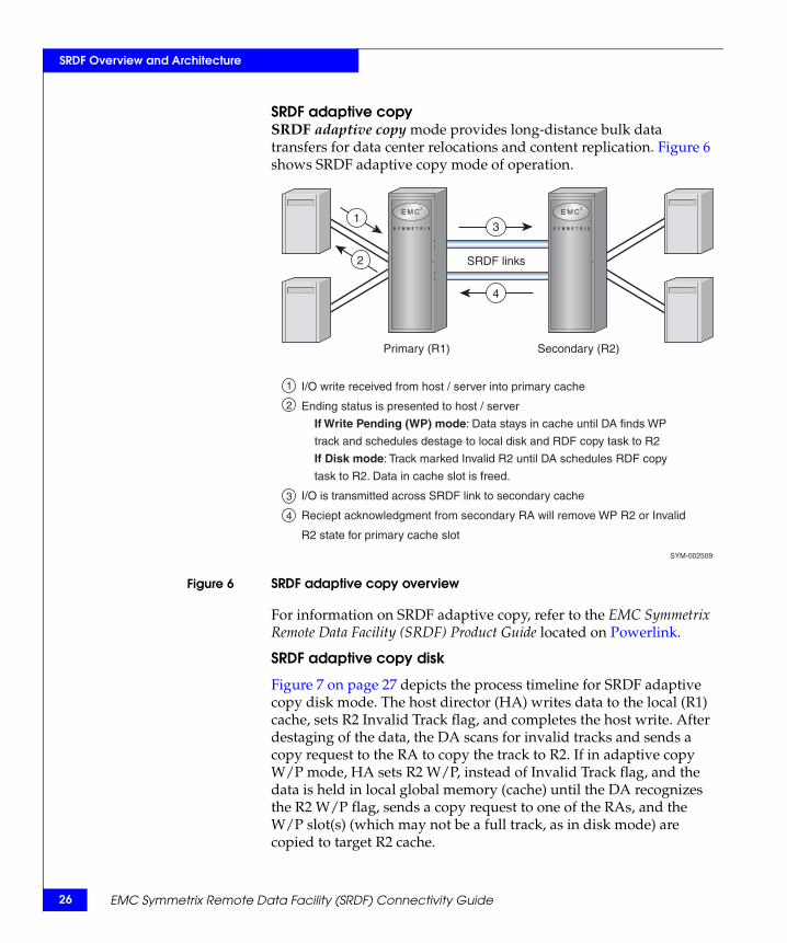
SRDF adaptive copySRDF adaptive copy mode provides long-distance bulk data transfers for data center relocations and content replication. Figure 6 shows SRDF adaptive copy mode of operation.
Figure 6 SRDF adaptive copy overview
For information on SRDF adaptive copy, refer to the EMC Symmetrix Remote Data Facility (SRDF) Product Guide located on Powerlink.
SRDF adaptive copy disk
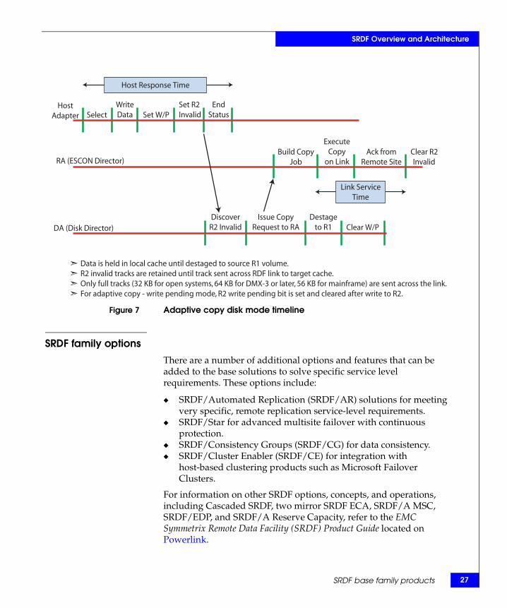
Figure 7 on page 27 depicts the process timeline for SRDF adaptive copy disk mode. The host director (HA) writes data to the local (R1) cache, sets R2 Invalid Track flag, and completes the host write. After destaging of the data, the DA scans for invalid tracks and sends a copy request to the RA to copy the track to R2. If in adaptive copy W/P mode, HA sets R2 W/P, instead of Invalid Track flag, and the data is held in local global memory (cache) until the DA recognizes the R2 W/P flag, sends a copy request to one of the RAs, and the W/P slot(s) (which may not be a full track, as in disk mode) are copied to target R2 cache.
SRDF links
Primary (R1) Secondary (R2)
1
2
3
4
I/O write received from host / server into primary cache
Ending status is presented to host / server
If Write Pending (WP) mode: Data stays in cache until DA finds WP
track and schedules destage to local disk and RDF copy task to R2
If Disk mode: Track marked Invalid R2 until DA schedules RDF copy
task to R2. Data in cache slot is freed.
I/O is transmitted across SRDF link to secondary cache
Reciept acknowledgment from secondary RA will remove WP R2 or Invalid
R2 state for primary cache slot
SYM-002509
13
4
2
EMC Symmetrix Remote Data Facility (SRDF) Connectivity Guide
SRDF Overview and Architecture
Figure 7 Adaptive copy disk mode timeline
SRDF family optionsThere are a number of additional options and features that can be added to the base solutions to solve specific service level requirements. These options include:
◆ SRDF/Automated Replication (SRDF/AR) solutions for meeting very specific, remote replication service-level requirements.
◆ SRDF/Star for advanced multisite failover with continuous protection.
◆ SRDF/Consistency Groups (SRDF/CG) for data consistency.◆ SRDF/Cluster Enabler (SRDF/CE) for integration with
host-based clustering products such as Microsoft Failover Clusters.
For information on other SRDF options, concepts, and operations, including Cascaded SRDF, two mirror SRDF ECA, SRDF/A MSC, SRDF/EDP, and SRDF/A Reserve Capacity, refer to the EMC Symmetrix Remote Data Facility (SRDF) Product Guide located on Powerlink.
HostAdapter Select
WriteData Set W/P
Set R2 Invalid
EndStatus
Host Response Time
Link ServiceTime
DA (Disk Director)Destage
to R1 Clear W/PIssue Copy
Request to RADiscover
R2 Invalid
RA (ESCON Director)Build Copy
Job
ExecuteCopy
on LinkAck from
Remote SiteClear R2Invalid
Data is held in local cache until destaged to source R1 volume.R2 invalid tracks are retained until track sent across RDF link to target cache.Only full tracks (32 KB for open systems, 64 KB for DMX-3 or later, 56 KB for mainframe) are sent across the link.For adaptive copy - write pending mode, R2 write pending bit is set and cleared after write to R2.
SRDF base family products 27
28
SRDF Overview and Architecture
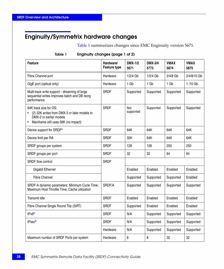
Enginuity/Symmetrix hardware changesTable 1 summarizes changes since EMC Enginuity version 5671.
Table 1 Enginuity changes (page 1 of 2)
Feature Hardware/ Feature type
DMX-1/25671
DMX-3/45773
VMAX5874
VMAX5875
Fibre Channel port Hardware 1/2/4 Gb 1/2/4 Gb 2/4/8 Gb 2/4/8/10 Gb
GigE port (optical only) Hardware 1 Gb 1 Gb 1 Gb 1 /10 Gb
Multi-track write support - streaming of large sequential writes improves batch and DB reorg performance
SRDF Supported Supported Supported Supported
64K track size for OS:• (2) 32K writes from DMX-3 or later models to
DMX-2 or earlier models• Mainframe still uses 56K (no impact)
SRDF Not supported
Supported Supported Supported
Device support for SRDFa SRDF 64K 64K 64K 64K
Device limit per RA SRDF 32K 64K 64K 64K
SRDF groups per system SRDF 128 128 250 250
SRDF groups per port SRDF 32 32 64 64
SRDF flow control: SRDF
Gigabit Ethernet Enabled Enabled Enabled Enabled
Fibre Channel Supported Supported Supported Enabled
SRDF-A dynamic parameters: Minimum Cycle Time; Maximum Host Throttle Time; Cache utilization
SRDF/A Supported Supported Supported Supported
Transmit Idle SRDF Enabled Enabled Enabled Enabled
Fibre Channel Single Round Trip (SiRT) SRDF Supported Enabled Enabled Enabled
IPv6b SRDF N/A Supported Supported Supported
IPsecb SRDF N/A Supported Supported Supported
Hardware N/A Supported Supported Supported
Maximum number of SRDF Ports per system Hardware 8 8 32 32
EMC Symmetrix Remote Data Facility (SRDF) Connectivity Guide
SRDF Overview and Architecture
a. For 64K device support, you need to have a minimum of two SRDF groups.
b. Requires new MPCD card for IPsec/IPV6 support on DMX: 293-801-982 = 4 GE; 293-801-984 = 2 FC + 2 GE; 293-801-986 = (3) FICON + (1) GigE, in place of 293-801-972 to -976 card for IPv4.
c. Hardware and software compression is available for GigE SRDF only.
d. Fibre Channel SRDF can use software compression only. Software compression must be enabled, since it is disabled by default.
GigE compression Hardwarec Enabled Enabled Enabled Enabled
Softwarec N/A N/A Supported Supported
Fibre Channel compression Softwared N/A N/A Supported Supported
Minimum SRDF/A Cycle Times SRDF 5 secs and 15 secs with MSC
1 sec and 3 secs with MSC
1 sec and 3 secs with MSC
1 sec and 3 secs with MSC
SRDF Delta Set Extension SRDF Supported Supported Supported Supported
Open Systems Multiple Writes per volume (<8) SRDF N/A Supported Supported Supported
Mainframe Multiple Writes per volume with PAV SRDF Supported Supported Supported Supported
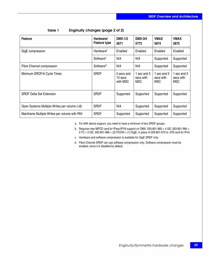
Table 1 Enginuity changes (page 2 of 2)
Feature Hardware/ Feature type
DMX-1/25671
DMX-3/45773
VMAX5874
VMAX5875
Enginuity/Symmetrix hardware changes 29

30
SRDF Overview and Architecture
EMC Symmetrix Remote Data Facility (SRDF) Connectivity Guide
2Invisible Body Tag
This chapter contains the following information on Symmetrix SRDF hardware:
◆ Symmetrix VMAX systems ................................................................. 32◆ Symmetrix DMX Series systems and earlier .................................... 38
Symmetrix SRDFHardware
Symmetrix SRDF Hardware 31
32
Symmetrix SRDF Hardware
Symmetrix VMAX systemsEMC Symmetrix VMAX systems are enterprise-class storage platforms intended for open systems and mainframe computing. Symmetrix VMAX systems run Enginuity version 5874 and later and are offered in two models:
◆ The highly-scalable Symmetrix VMAX system
◆ The single engine Symmetrix VMAX SE system
This section contains the following information:
◆ “Symmetrix VMAX engine” on page 32
◆ “Front End I/O modules” on page 33
Symmetrix VMAX engine
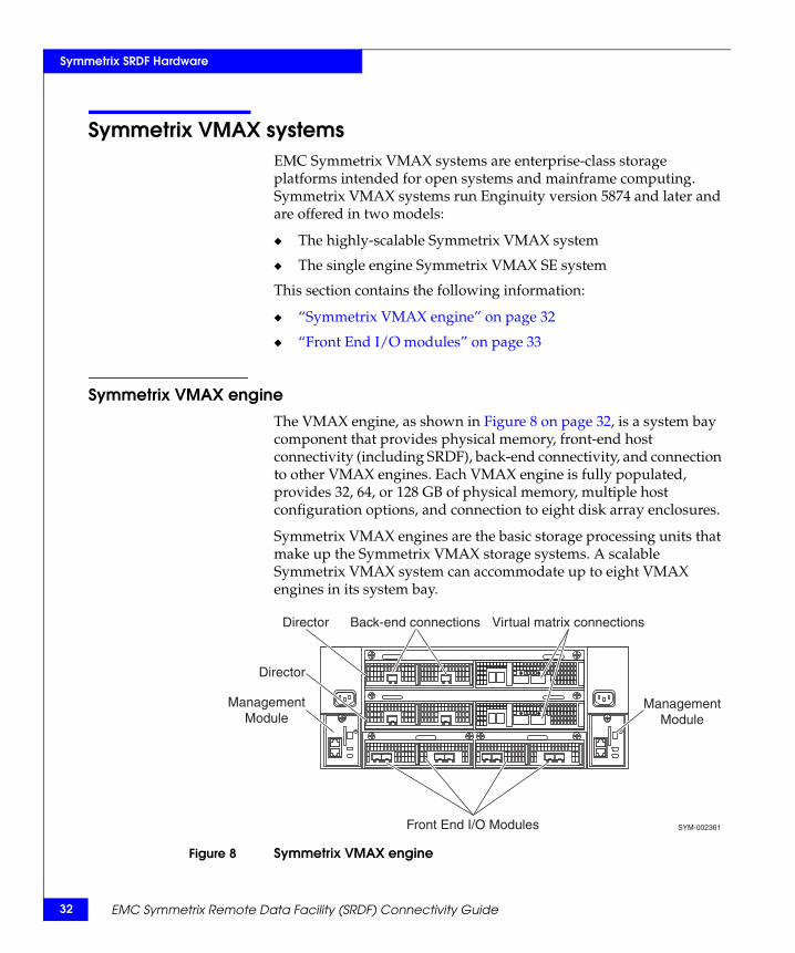
The VMAX engine, as shown in Figure 8 on page 32, is a system bay component that provides physical memory, front-end host connectivity (including SRDF), back-end connectivity, and connection to other VMAX engines. Each VMAX engine is fully populated, provides 32, 64, or 128 GB of physical memory, multiple host configuration options, and connection to eight disk array enclosures.
Symmetrix VMAX engines are the basic storage processing units that make up the Symmetrix VMAX storage systems. A scalable Symmetrix VMAX system can accommodate up to eight VMAX engines in its system bay.
Figure 8 Symmetrix VMAX engine
SYM-002361
Back-end connections
Director
Front End I/O Modules
ManagementModule
Virtual matrix connections
ManagementModule
Director
EMC Symmetrix Remote Data Facility (SRDF) Connectivity Guide
Symmetrix SRDF Hardware
The Symmetrix VMAX engine consists of:
◆ Two redundant (odd, even) directors providing CPU processing power, memory, and back-end connectivity via Fibre Channel Back End I/O modules)
◆ Four Front End I/O modules (two per director) that provide front-end and SRDF connectivity. Front End I/O modules reside in the Front End I/O module carriers that also support hardware compression for GigE SRDF configurations.
Note: Hardware compression is enabled by default when using SRDF over GigE.
◆ Virtual Matrix Interface that provides engine-to-engine connectivity
◆ Two engine power supplies
◆ Two management modules
Link speeds are:
◆ 2/4/8 Gbs for Fibre Channel
◆ 1 or 10 Gbs for GigE
Front End I/O modulesSymmetrix VMAX systems support the following Front End I/O modules:
◆ Fibre Channel
◆ GigE
◆ FICON
Fibre Channel and GigE Front End I/O modules can be configured for SRDF connectivity. If the VMAX Engine provides SRDF connectivity, some of the front-end ports are dedicated to SRDF while the rest are still available to hosts to provide front-end connectivity.
Table 2 on page 34 through Table 6 on page 37 show a range of front-end and SRDF port configurations supported in a single VMAX Engine.
Symmetrix VMAX systems 33
34
Symmetrix SRDF Hardware
This section describes I/O models, port type, and port capacity for the following typical front-end configurations:
◆ “Fibre Channel I/O modules” on page 34
◆ “GigE I/O modules” on page 34
◆ “Mixed Fibre Channel and GigE I/O modules” on page 35
◆ “Fibre Channel and FICON I/O modules” on page 36
◆ “FICON and GigE I/O modules” on page 37
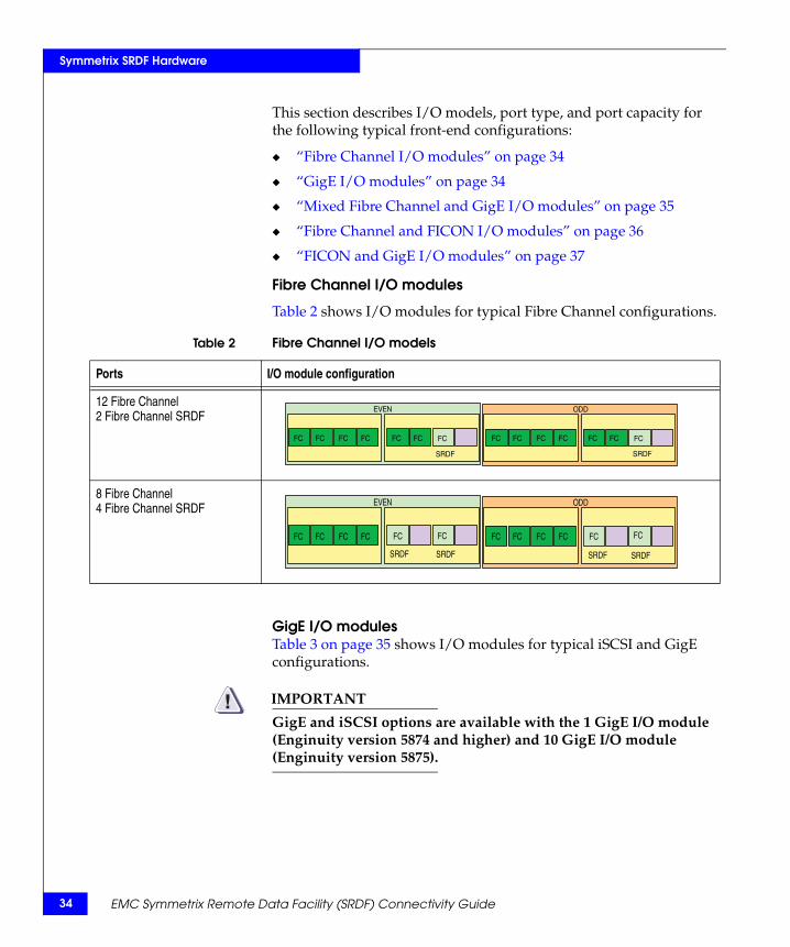
Fibre Channel I/O modules
Table 2 shows I/O modules for typical Fibre Channel configurations.
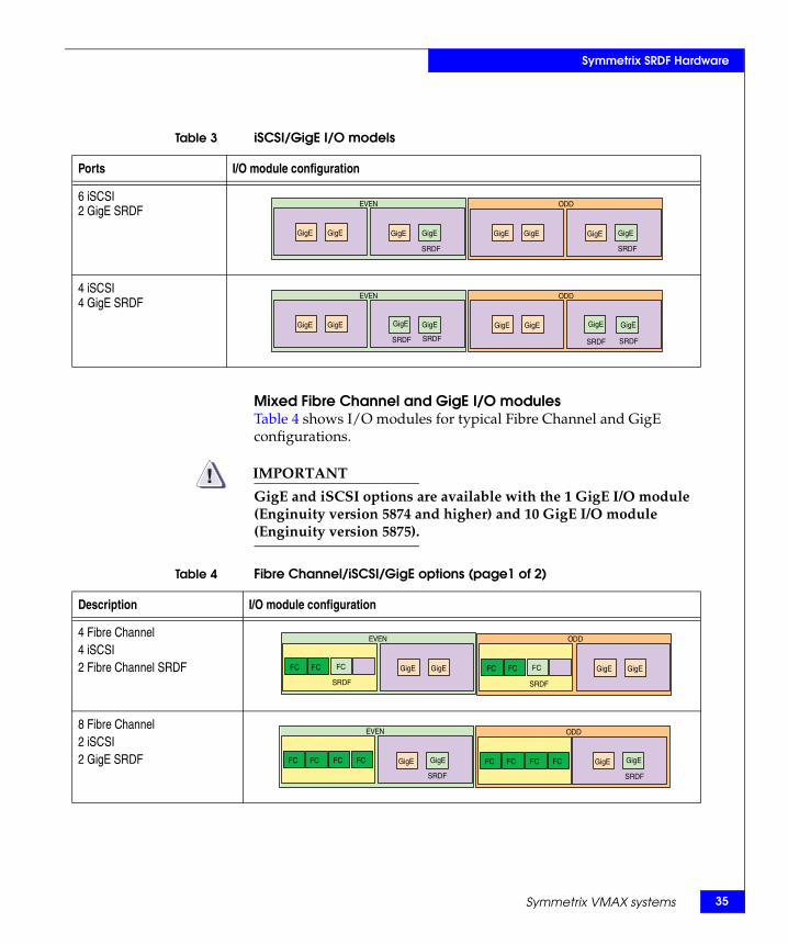
GigE I/O modulesTable 3 on page 35 shows I/O modules for typical iSCSI and GigE configurations.
IMPORTANT!GigE and iSCSI options are available with the 1 GigE I/O module (Enginuity version 5874 and higher) and 10 GigE I/O module (Enginuity version 5875).
Table 2 Fibre Channel I/O models
Ports I/O module configuration
12 Fibre Channel 2 Fibre Channel SRDF
8 Fibre Channel 4 Fibre Channel SRDF
ODDEVEN
FC FC FC FC FC FC
SRDF
FC FC FC FC FC FC FC
SRDF
FC
ODDEVEN
FC FC FC FC
SRDF SRDF
FC FC FC FCFC
SRDF SRDF
FC FC FC
EMC Symmetrix Remote Data Facility (SRDF) Connectivity Guide
Symmetrix SRDF Hardware
Mixed Fibre Channel and GigE I/O modulesTable 4 shows I/O modules for typical Fibre Channel and GigE configurations.
IMPORTANT!GigE and iSCSI options are available with the 1 GigE I/O module (Enginuity version 5874 and higher) and 10 GigE I/O module (Enginuity version 5875).
Table 3 iSCSI/GigE I/O models
Ports I/O module configuration
6 iSCSI 2 GigE SRDF
4 iSCSI 4 GigE SRDF
ODDEVEN
GigE GigE GigE
SRDF
GigE GigE GigE
SRDF
GigEGigE
ODDEVEN
GigE GigE
SRDF SRDF
GigE GigEGigEGigE
SRDF SRDF
GigE GigE
Table 4 Fibre Channel/iSCSI/GigE options (page1 of 2)
Description I/O module configuration
4 Fibre Channel 4 iSCSI 2 Fibre Channel SRDF
8 Fibre Channel 2 iSCSI 2 GigE SRDF
ODDEVEN
GigE GigE GigE GigEFC FC
SRDF
FC FC
SRDF
FCFC
ODDEVEN
GigE
SRDF
GigE GigEFC FC FC FC FC FC FC FC GigE
SRDF
Symmetrix VMAX systems 35
36
Symmetrix SRDF Hardware
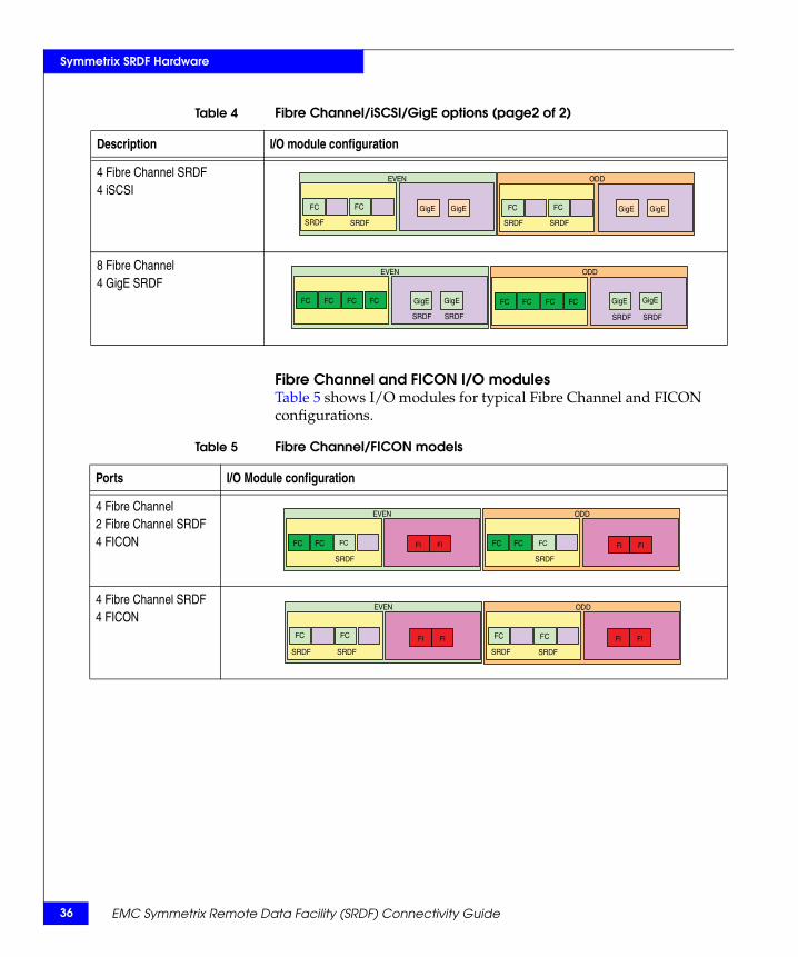
Fibre Channel and FICON I/O modulesTable 5 shows I/O modules for typical Fibre Channel and FICON configurations.
4 Fibre Channel SRDF 4 iSCSI
8 Fibre Channel 4 GigE SRDF
Table 4 Fibre Channel/iSCSI/GigE options (page2 of 2)
Description I/O module configuration
ODDEVEN
GigE GigE GigE GigE
SRDF SRDF SRDF SRDF
FCFC FC FC
ODDEVEN
SRDF SRDF SRDF SRDF
GigE GigE GigE GigEFC FC FCFC FC FC FC FC
Table 5 Fibre Channel/FICON models
Ports I/O Module configuration
4 Fibre Channel 2 Fibre Channel SRDF 4 FICON
4 Fibre Channel SRDF4 FICON
ODDEVEN
FC FC
SRDF
FC FC
SRDF
FI FI FI FIFC FC
ODDEVEN
SRDF SRDF
FC FC
SRDF SRDF
FI FI FI FIFC FC
EMC Symmetrix Remote Data Facility (SRDF) Connectivity Guide
Symmetrix SRDF Hardware
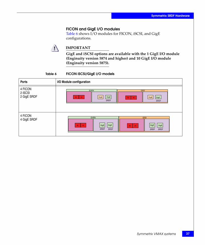
FICON and GigE I/O modulesTable 6 shows I/O modules for FICON, iSCSI, and GigE configurations.
IMPORTANT!GigE and iSCSI options are available with the 1 GigE I/O module (Enginuity version 5874 and higher) and 10 GigE I/O module (Enginuity version 5875).
Table 6 FICON iSCSI/GigE I/O models
Ports I/O Module configuration
4 FICON2 iSCSI2 GigE SRDF
4 FICON4 GigE SRDF
ODDEVEN
GigE
SRDF
GigE GigE
SRDF
GigEFI FI FI FI
ODDEVEN
SRDF SRDF SRDF SRDF
GigE GigE GigE GigEFI FI FI FI
Symmetrix VMAX systems 37
38
Symmetrix SRDF Hardware
Symmetrix DMX Series systems and earlierThis section contains the following information on the Symmetrix DMX Series, and earlier, systems:
◆ “SRDF director hardware” on page 38
◆ “SRDF director functions” on page 39
◆ “ESCON director (RA)” on page 40
◆ “Fibre Channel director (RF)” on page 41
◆ “Gigabit Ethernet director (RE) on Symmetrix 8000” on page 43
◆ “Multiprotocol Channel Director on the Symmetrix DMX series” on page 44
SRDF director hardwareSRDF director hardware consists of a director and adapter board set. This hardware provides the communications physical layer for SRDF data and information exchanges between Symmetrix systems. SRDF director hardware includes any of four types of director/adapter board sets, depending on the protocol:
◆ ESCON remote adapter (RA), page 40.
Note: ESCON is not supported with Enginuity version 5874.
◆ Fibre Channel remote adapter (RF), page 41.
◆ GigE remote adapter (RE), page 43.
◆ Multiprotocol Channel Director (MPCD), supported with Symmetrix DMX series, and configurable for SRDF over Gigabit Ethernet (GigE), page 44. With DMX-3, Fibre Channel was added. The MPCD is also configurable for iSCSI, FICON, or combinations of these protocols.
The SRDF network options listed above can be used for any host environment. SRDF uses a storage protocol based on the Gigabit Ethernet, Fibre Channel FC-4, or ESCON specifications to remotely mirror data between Symmetrix systems. The host attachment, I/O protocol, and disk data structures that each host requires are independent of the SRDF operation between Symmetrix systems.
EMC Symmetrix Remote Data Facility (SRDF) Connectivity Guide
Symmetrix SRDF Hardware
Note: Some restrictions apply in mixed environments with iSeries and other host types. For more information, consult EMC Customer Support.
CAUTION!EMC recommends that the Symmetrix system has at least two director board sets for SRDF protection; one processor on each board for SRDF to provide redundant links in case a communications link fails or in the unlikely event a director fails. Having two director boards for SRDF avoids a potential single point of failure if one processor on the director is used for SRDF and the other processor(s) is/are used to connect to a host.
SRDF director functions
The SRDF director/adapter board sets, further described in “Symmetrix DMX Series systems and earlier” on page 38, provide the link connections. Along with the fiber-optic protocol support, they are integral in controlling communications between two Symmetrix systems in an SRDF configuration.
GigE remote directors (RE) or Fibre Channel remote directors (RF) maintain a peer-to-peer relationship at the transport layer of communications.
The ESCON remote director (RA) board set that normally sends data across an SRDF link is known as an RA-1. An RA-1 functions like a host channel interface. The ESCON RA board set that normally receives data sent across an SRDF link is known as an RA-2. An RA-2 functions like a storage director interface.
An RA-1 and its corresponding RA-2 are known as an RA pair.
◆ With Symmetrix 3xxx or 5xxx models, there can be multiple RA pairs in an SRDF configuration, up to a maximum of 16 pairs.
◆ With Symmetrix 8xxx models, an optional four-processor ESCON board can be used for SRDF.
◆ With Symmetrix DMX-4 models, an optional eight-port four-processor ESCON board can be used for SRDF.
◆ ESCON is not supported with Symmetrix VMAX and Symmetrix VMAX SE systems.
Symmetrix DMX Series systems and earlier 39
40
Symmetrix SRDF Hardware
Note: Each Symmetrix product guide, available on Powerlink, provides detailed descriptions of the SRDF-supported hardware functionality.
ESCON director (RA)
Note: ESCON is not supported with Enginuity version 5874 and later.
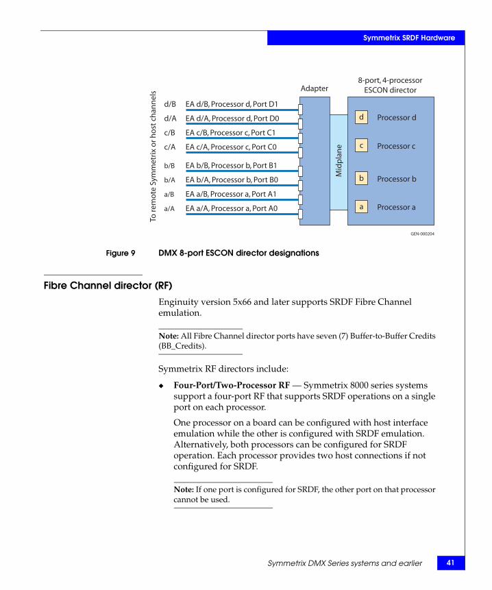
A Symmetrix 8000 RA contains four individual processors (CPUs) (Figure 9 on page 41). A Symmetrix 3x30/5x30 RA contains two processors. Each processor can provide one SRDF port connection. On one board, a processor can be configured with host interface emulation while the other processor(s) is configured with SRDF emulation. Alternatively, all processors on the board can be configured for SRDF emulation. All ESCON ports are 1310 nm multimode.
Each processor provides two host connections if not configured for SRDF. If one port is configured for SRDF, the other port on that processor cannot be used.
The Symmetrix DMX ESCON director contains four processors (CPUs) and eight interfaces to host mainframe systems or four interfaces for SRDF connections. Each processor can provide one SRDF port connection. On one board, a processor can be configured with host interface emulation while the other processor(s) is configured with SRDF emulation. Alternatively, all processors on the board can be configured for SRDF emulation.
EMC Symmetrix Remote Data Facility (SRDF) Connectivity Guide
Symmetrix SRDF Hardware
Figure 9 DMX 8-port ESCON director designations
Fibre Channel director (RF)
Enginuity version 5x66 and later supports SRDF Fibre Channel emulation.
Note: All Fibre Channel director ports have seven (7) Buffer-to-Buffer Credits (BB_Credits).
Symmetrix RF directors include:
◆ Four-Port/Two-Processor RF — Symmetrix 8000 series systems support a four-port RF that supports SRDF operations on a single port on each processor.
One processor on a board can be configured with host interface emulation while the other is configured with SRDF emulation. Alternatively, both processors can be configured for SRDF operation. Each processor provides two host connections if not configured for SRDF.
Note: If one port is configured for SRDF, the other port on that processor cannot be used.
EA d/B, Processor d, Port D1
EA d/A, Processor d, Port D0
EA c/B, Processor c, Port C1
EA c/A, Processor c, Port C0
EA b/B, Processor b, Port B1
EA b/A, Processor b, Port B0
EA a/B, Processor a, Port A1
EA a/A, Processor a, Port A0
d/B
d/A
c/B
c/A
b/B
b/A
a/B
a/A
To re
mot
e Sy
mm
etrix
or h
ost c
hann
els
d
c
b
a Processor a
Processor b
Processor c
Processor d
Mid
plan
e
GEN-000204
Adapter8-port, 4-processor
ESCON director
Symmetrix DMX Series systems and earlier 41
42
Symmetrix SRDF Hardware
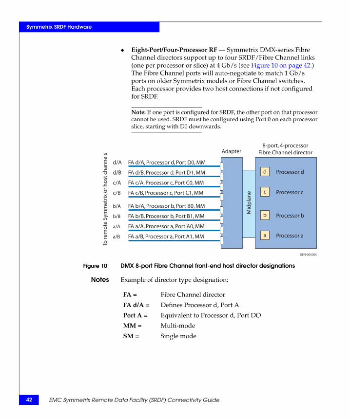
◆ Eight-Port/Four-Processor RF — Symmetrix DMX-series Fibre Channel directors support up to four SRDF/Fibre Channel links (one per processor or slice) at 4 Gb/s (see Figure 10 on page 42.) The Fibre Channel ports will auto-negotiate to match 1 Gb/s ports on older Symmetrix models or Fibre Channel switches. Each processor provides two host connections if not configured for SRDF.
Note: If one port is configured for SRDF, the other port on that processor cannot be used. SRDF must be configured using Port 0 on each processor slice, starting with D0 downwards.
Figure 10 DMX 8-port Fibre Channel front-end host director designations
Notes Example of director type designation:
FA d/A, Processor d, Port D0, MM
FA d/B, Processor d, Port D1, MM
FA c/A, Processor c, Port C0, MM
FA c/B, Processor c, Port C1, MM
FA b/A, Processor b, Port B0, MM
FA b/B, Processor b, Port B1, MM
FA a/A, Processor a, Port A0, MM
FA a/B, Processor a, Port A1, MM
d/A
d/B
c/A
c/B
b/A
b/B
a/A
a/B
To re
mot
e Sy
mm
etrix
or h
ost c
hann
els
d
c
b
a Processor a
Processor b
Processor c
Processor d
Mid
plan
eGEN-000205
Adapter8-port, 4-processor
Fibre Channel director
FA = Fibre Channel director
FA d/A = Defines Processor d, Port A
Port A = Equivalent to Processor d, Port DO
MM = Multi-mode
SM = Single mode
EMC Symmetrix Remote Data Facility (SRDF) Connectivity Guide
Symmetrix SRDF Hardware
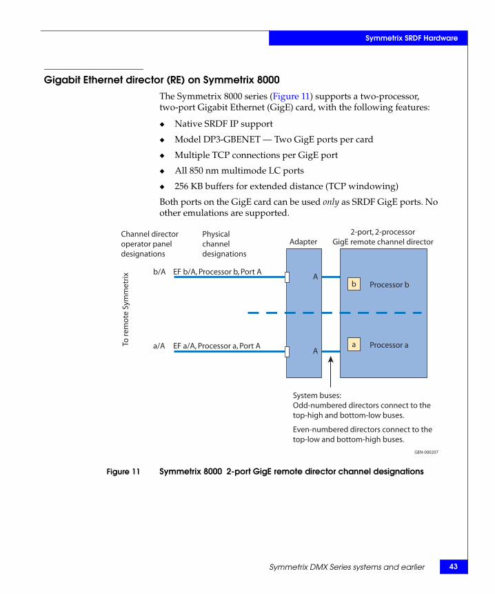
Gigabit Ethernet director (RE) on Symmetrix 8000The Symmetrix 8000 series (Figure 11) supports a two-processor, two-port Gigabit Ethernet (GigE) card, with the following features:
◆ Native SRDF IP support
◆ Model DP3-GBENET — Two GigE ports per card
◆ Multiple TCP connections per GigE port
◆ All 850 nm multimode LC ports
◆ 256 KB buffers for extended distance (TCP windowing)
Both ports on the GigE card can be used only as SRDF GigE ports. No other emulations are supported.
Figure 11 Symmetrix 8000 2-port GigE remote director channel designations
A
A
EF b/A, Processor b, Port A
EF a/A, Processor a, Port ATo re
mot
e Sy
mm
etrix
a Processor a
b Processor b
GEN-000207
Physicalchanneldesignations
Channel directoroperator paneldesignations
2-port, 2-processorGigE remote channel director
b/A
a/A
Adapter
System buses:Odd-numbered directors connect to thetop-high and bottom-low buses.
Even-numbered directors connect to thetop-low and bottom-high buses.
Symmetrix DMX Series systems and earlier 43
44
Symmetrix SRDF Hardware
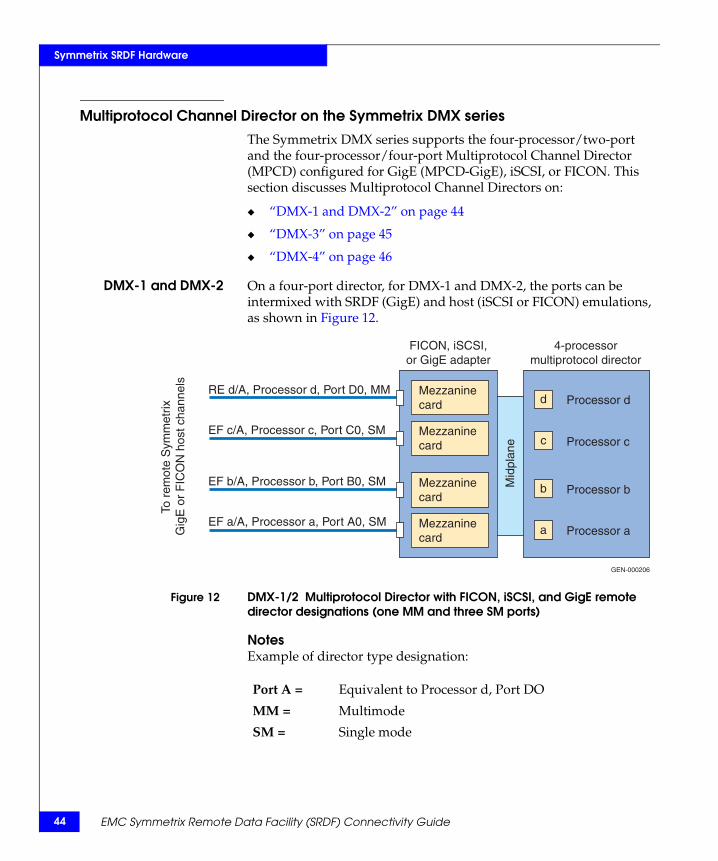
Multiprotocol Channel Director on the Symmetrix DMX seriesThe Symmetrix DMX series supports the four-processor/two-port and the four-processor/four-port Multiprotocol Channel Director (MPCD) configured for GigE (MPCD-GigE), iSCSI, or FICON. This section discusses Multiprotocol Channel Directors on:
◆ “DMX-1 and DMX-2” on page 44
◆ “DMX-3” on page 45
◆ “DMX-4” on page 46
DMX-1 and DMX-2 On a four-port director, for DMX-1 and DMX-2, the ports can be intermixed with SRDF (GigE) and host (iSCSI or FICON) emulations, as shown in Figure 12.
Figure 12 DMX-1/2 Multiprotocol Director with FICON, iSCSI, and GigE remote director designations (one MM and three SM ports)
NotesExample of director type designation:
RE d/A, Processor d, Port D0, MM
EF c/A, Processor c, Port C0, SM
EF b/A, Processor b, Port B0, SM
EF a/A, Processor a, Port A0, SM
To r
emot
e S
ymm
etrix
Gig
E o
r F
ICO
N h
ost c
hann
els
d
c
b
a Processor a
Processor b
Processor c
Processor d
Mid
plan
e
GEN-000206
FICON, iSCSI,or GigE adapter
4-processormultiprotocol director
Mezzaninecard
Mezzaninecard
Mezzaninecard
Mezzaninecard
Port A = Equivalent to Processor d, Port DO
MM = Multimode
SM = Single mode
EMC Symmetrix Remote Data Facility (SRDF) Connectivity Guide
Symmetrix SRDF Hardware
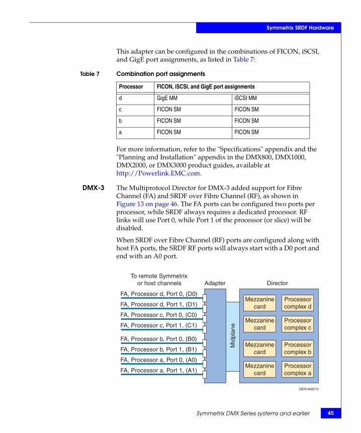
This adapter can be configured in the combinations of FICON, iSCSI, and GigE port assignments, as listed in Table 7:
For more information, refer to the "Specifications" appendix and the "Planning and Installation" appendix in the DMX800, DMX1000, DMX2000, or DMX3000 product guides, available at http://Powerlink.EMC.com.
DMX-3 The Multiprotocol Director for DMX-3 added support for Fibre Channel (FA) and SRDF over Fibre Channel (RF), as shown in Figure 13 on page 46. The FA ports can be configured two ports per processor, while SRDF always requires a dedicated processor. RF links will use Port 0, while Port 1 of the processor (or slice) will be disabled.
When SRDF over Fibre Channel (RF) ports are configured along with host FA ports, the SRDF RF ports will always start with a D0 port and end with an A0 port.
Table 7 Combination port assignments
Processor FICON, iSCSI, and GigE port assignments
d GigE MM iSCSI MM
c FICON SM FICON SM
b FICON SM FICON SM
a FICON SM FICON SM
FA, Processor d, Port 0, (D0)
FA, Processor d, Port 1, (D1)
FA, Processor c, Port 0, (C0)
FA, Processor c, Port 1, (C1)
FA, Processor b, Port 0, (B0)
FA, Processor b, Port 1, (B1)
FA, Processor a, Port 0, (A0)
FA, Processor a, Port 1, (A1)
Mid
plan
e
GEN-000213
Adapter DirectorTo remote Symmetrix
or host channels
Mezzaninecard
Mezzaninecard
Mezzaninecard
Mezzaninecard
Processorcomplex d
Processorcomplex c
Processorcomplex b
Processorcomplex a
Symmetrix DMX Series systems and earlier 45
46
Symmetrix SRDF Hardware
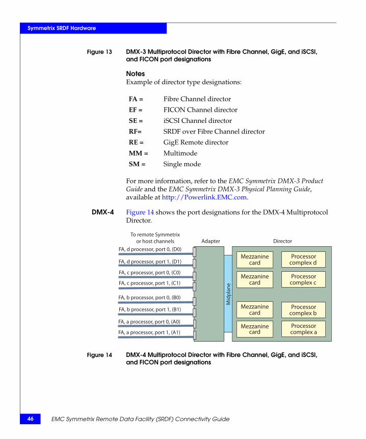
Figure 13 DMX-3 Multiprotocol Director with Fibre Channel, GigE, and iSCSI, and FICON port designations
NotesExample of director type designations:
For more information, refer to the EMC Symmetrix DMX-3 Product Guide and the EMC Symmetrix DMX-3 Physical Planning Guide, available at http://Powerlink.EMC.com.
DMX-4 Figure 14 shows the port designations for the DMX-4 Multiprotocol Director.
Figure 14 DMX-4 Multiprotocol Director with Fibre Channel, GigE, and iSCSI, and FICON port designations
FA = Fibre Channel director
EF = FICON Channel director
SE = iSCSI Channel director
RF= SRDF over Fibre Channel director
RE = GigE Remote director
MM = Multimode
SM = Single mode
Mid
plan
eTo remote Symmetrix
or host channels DirectorAdapter
FA, a processor, port 1, (A1)
FA, a processor, port 0, (A0)
FA, b processor, port 1, (B1)
FA, b processor, port 0, (B0)
FA, c processor, port 1, (C1)
FA, c processor, port 0, (C0)
FA, d processor, port 1, (D1)
FA, d processor, port 0, (D0)
Mezzaninecard
Mezzaninecard
Mezzaninecard
Mezzaninecard
Processorcomplex d
Processorcomplex c
Processorcomplex b
Processorcomplex a
EMC Symmetrix Remote Data Facility (SRDF) Connectivity Guide
Symmetrix SRDF Hardware
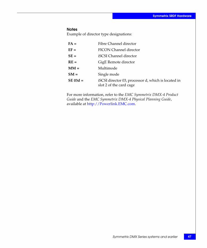
NotesExample of director type designations:
For more information, refer to the EMC Symmetrix DMX-4 Product Guide and the EMC Symmetrix DMX-4 Physical Planning Guide, available at http://Powerlink.EMC.com.
FA = Fibre Channel director
EF = FICON Channel director
SE = iSCSI Channel director
RE = GigE Remote director
MM = Multimode
SM = Single mode
SE 03d = iSCSI director 03, processor d, which is located in slot 2 of the card cage
Symmetrix DMX Series systems and earlier 47

48
Symmetrix SRDF Hardware
EMC Symmetrix Remote Data Facility (SRDF) Connectivity Guide
3Invisible Body Tag
SRDF uses Gigabit Ethernet, Fibre Channel, or ESCON network protocols to move data across the SRDF links. This chapter discusses each of these protocols:
◆ Gigabit Ethernet ................................................................................. 50◆ Fibre Channel...................................................................................... 60◆ ESCON................................................................................................. 83
SRDF NetworkProtocols
SRDF Network Protocols 49

50
SRDF Network Protocols
Gigabit Ethernet This section contains information on implementing SRDF over Gigabit Ethernet and IP.
Generic considerations
Latency Latency is generally referred to in milliseconds (ms) and as the combined round trip time (RTT) between primary and secondary Symmetrix systems. Latency should be as low as possible at the given distances separating the sites. The round trip latency of the SRDF network is the time (ms) it takes for a full-size Ethernet packet (1500 bytes) to travel from the GigE port in one Symmetrix, over an IP network, to the Gigabit port in another Symmetrix, and back again. One millisecond is equal to 0.001 seconds; therefore, 1000 ms is equal to one second. Therefore, it takes roughly 1 ms for light to travel 200 km or 125 circuit miles one way.
Flow control Flow controls are necessary because senders and receivers are often unmatched in capacity and processing power. A receiver might not be able to process packets at the same speed as the sender, causing the receiver to send a pause message to its link partner to temporarily reduce the amount of data it’s transmitting. With Gigabit Ethernet, if buffers fill, packets are dropped. The goal of flow-control mechanisms is to prevent dropped packets that then must be retransmitted.
Note: In order for flow control to work properly with Gigabit Ethernet switch ports, auto negotiation must be on.
Starting with Enginuity version 5670, the GigE director has a built-in flow control mechanism to control the amount of data placed in the SRDF queue to be transmitted to the secondary side. The SRDF flow control mechanism keeps track of how many I/Os are being sent across the link, and dynamically adjusts the number of I/Os waiting in the job queue. This prevents I/Os from timing out while in the queue or when sent across the link.
When packets are lost in transit over the network, TCP has Slow Start and Congestion Avoidance algorithms to reduce the number of packets being sent. When packet loss is encountered, Slow Start will start by sending a single packet and waiting for an ACK
EMC Symmetrix Remote Data Facility (SRDF) Connectivity Guide
SRDF Network Protocols
(acknowledgement), then send two packets and wait for an ACK, then four packets, and so on. This exponential increase will continue until it reaches a window size of half the size of the one in which the packet loss had occurred. After this halfway value is reached, Congestion Avoidance takes over and the increase in the window size should be at most one packet each round trip time.
This mechanism was designed for handling small numbers of packets in a network with packet loss. When the network becomes congested, packets are dropped. Traditional TCP has a tendency to overreact to packet drops by halving the TCP window size. The resulting reduction in throughput that can occur in traditional TCP implementations is unacceptable to many storage applications.
Starting with Enginuity version 5671, DMX GigE supports the option to disable TCP Slow Start.
Note: This option is only available through EMC Customer Service.
For dedicated bandwidth and loss-less network configurations, it is recommended to disable TCP Slow Start. By disabling TCP Slow Start, the DMX GigE director will not back off to 5% I/O rate during retransmissions. Instead, it will try to maintain I/O rate just below the Speed Limit setting. It is also recommended to set Speed Limit at 90% of available bandwidth per GigE port.
Starting with Enginuity version 5772, TCP Slow Start is disabled by default.
Network quality A well-designed network should provide latencies that are as low as possible, with the number of hops kept to a minimum given the geographical distance separating the sites.
For SRDF/S, the acceptable round trip time (RTT) is dependent on application tolerance to latency. A best practice, however, is for latency between SRDF ports to not exceed 5ms RTT. Packet loss should never exceed 0.1%. It is recommended, however, that packet loss should not exceed 0.01% over any one-second period and should be as close to 0% as possible.
SRDF/A and SRDF adaptive copy are extensively tested against what is referred to as the distance envelope. This involves a series of stringent tests to ensure that SRDF continues to function with latencies to a maximum of 200 ms RTT and a packet loss up to 1%. It is recommended, however, that packet loss not exceed 0.1% for these SRDF modes.
Gigabit Ethernet 51
52
SRDF Network Protocols
Networks that experience packet loss greater than the recommended figures mentioned above are considered poor-quality links and will severely impact throughput rates. SRDF can be impacted as follows:
◆ SRDF traffic slows down due to packet retransmissions and retries
◆ With SRDF/S, host response times will significantly increase resulting in application timeouts
◆ SRDF links might start continuously bouncing
◆ Symmetrix remote adapter resources are wasted on unhealthy links
Packets should not be delivered out of order. This will result in SRDF link bounces or will create a major degradation in performance. The rapid variation in the latency on the network (known as jitter) should also be as low as possible.
Note: Latency jitter (the variance in latency) should not exceed either 25% of the average network latency or 25ms, which ever is the lower number.
For poor-quality networks, it is highly recommended to utilize WAN optimization devices qualified by EMC E-Lab™.
Note: WAN optimization appliances deployed within IP networks are qualified by EMC. Consult the EMC Support Matrix for WAN optimization appliances that can be used with SRDF. For more information on WAN optimization, refer to “WAN optimization” on page 102.
EMC Symmetrix Remote Data Facility (SRDF) Connectivity Guide
SRDF Network Protocols
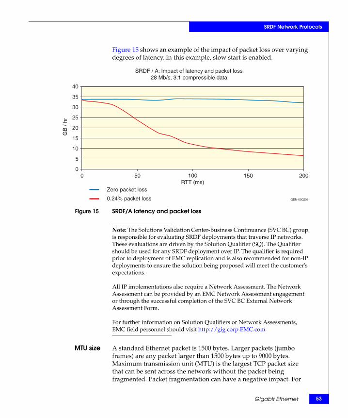
Figure 15 shows an example of the impact of packet loss over varying degrees of latency. In this example, slow start is enabled.
Figure 15 SRDF/A latency and packet loss
Note: The Solutions Validation Center-Business Continuance (SVC BC) group is responsible for evaluating SRDF deployments that traverse IP networks. These evaluations are driven by the Solution Qualifier (SQ). The Qualifier should be used for any SRDF deployment over IP. The qualifier is required prior to deployment of EMC replication and is also recommended for non-IP deployments to ensure the solution being proposed will meet the customer's expectations.
All IP implementations also require a Network Assessment. The Network Assessment can be provided by an EMC Network Assessment engagement or through the successful completion of the SVC BC External Network Assessment Form.
For further information on Solution Qualifiers or Network Assessments, EMC field personnel should visit http://gig.corp.EMC.com.
MTU size A standard Ethernet packet is 1500 bytes. Larger packets (jumbo frames) are any packet larger than 1500 bytes up to 9000 bytes. Maximum transmission unit (MTU) is the largest TCP packet size that can be sent across the network without the packet being fragmented. Packet fragmentation can have a negative impact. For
Zero packet loss
0.24% packet loss
SRDF / A: Impact of latency and packet loss28 Mb/s, 3:1 compressible data
GEN-000208
40
35
30
25
20
15
10
5
00 50 100
RTT (ms)150 200
GB
/ hr
Gigabit Ethernet 53
54
SRDF Network Protocols
instance, packets may not be reassembled or packets may be dropped. Fragmentation can cause such a high processor load on the device performing the fragmentation (for example, routers, encryptors, etc.) that it can severally impact (limit) throughput and/or cause the dropping of packets. To prevent packet fragmentation, verify that every device in the network path has the same MTU value set and that the MTU size is not exceeded.
Compression Data compression is the process of encoding information using fewer bits than an unencoded representation would use through the use of specific encoding schemes. This is accomplished through algorithms looking for data having statistical redundancy. Compression programs simply eliminate the redundancy. Instead of repeating data over and over again, a compression program will store the data once and then refer back to it whenever it appears in the original data stream.
Dedicated external compression devices are available today and are capable of achieving ratios much greater than devices that are not dedicated to compression. Keep in mind the following characteristics:
◆ Software compression is typically a lower cost option suited more for lower bandwidth environments.
◆ Hardware compression is typically a higher cost option, but more suitable for higher bandwidth environments.
◆ Efficiency of the compression is dependent on the algorithms used and the compressibility of the data (random versus sequential).
Encryption Encryption devices can be used to ensure the secrecy of data transmitted between two points. Encryption refers to algorithmic schemes that encode plain text into nonreadable form or cyphertext. The receiver of the encrypted text uses a key to decrypt the message, returning it to its original plain text form. A key is a randomly or user-generated set of numbers and/or characters used to encrypt and/or decrypt information. There are many types of encryption and not all are reliable.
Note: Third-party encryption devices are not qualified by EMC. These devices can be used with SRDF. Recommended encryption devices can be found in the EMC Select Catalog available at http://Powerlink.EMC.com.
EMC Symmetrix Remote Data Facility (SRDF) Connectivity Guide
SRDF Network Protocols
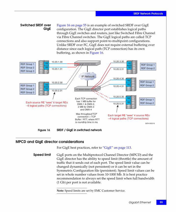
Switched SRDF overGigE
Figure 16 on page 55 is an example of switched SRDF over GigE configuration. The GigE director port establishes logical paths through GigE switches and routers, just like Switched Fibre Channel via Fibre Channel switches. The GigE logical paths are called TCP connections and also support point-to-multipoint configurations. Unlike SRDF over FC, GigE does not require external buffering over distance since each logical path (TCP connection) has its own buffering, as shown in Figure 16.
Figure 16 SRDF / GigE in switched network
MPCD and GigE director considerations
For GigE best practices, refer to “GigE” on page 113.
Speed limit GigE ports on the Multiprotocol Channel Director (MPCD) and the GigE director has the ability to speed limit (throttle) the amount of traffic that it sends out of each port. The speed limit value can be changed dynamically (not persistent) or it can be set in the Symmetrix Configuration file (persistent). Speed limit values can be set in whole number values from 10-1000 Mb. It is best practice recommendation to always set the speed limit when full bandwidth (1 Gb) per port is not available.
Note: Speed limits are set by EMC Customer Service.
Each source RE “sees” 6 target REs --6 logical paths (TCP connections)
Each target RE “sees” 4 source REs --4 logical paths (TCP connections)
Each TCP connectionhas 1 MB buffer forDMX-1 & DMX-2,2 MB for DMX-3
and DMX-4
Max throughput/TCP connection = TCP
Buffer / RTT, where RTT is roundtrip time in ms
10.20.1.30
10.20.1.31
10.20.2.30
10.20.2.31
10.20.3.30
10.20.3.31
10.20.4.30
10.20.4.31
10.20.5.30
10.20.5.31
GEN-000216
IP Network
RDF Group 1
RDF Group 2
RDF Group 3
RE
RE
RDF Group 1
RDF Group 2
RDF Group 3
RE
RE
RDF Group 1
RDF Group 2
RE
RE
RDF Group 1
RDF Group 2
RE
RE
RDF Group 1
RDF Group 2
RE
RE
Gigabit Ethernet 55
56
SRDF Network Protocols
Speed limit can be configured on a per port basis or across a group of ports (recommended) using a new feature in 5772 code called "auto-adjust" speed limit. With auto-adjusting speed limits, you will combine a set of SRDF over GigE directors into a single speed limit group with an aggregate bandwidth for the entire speed limit group. Each SRDF port will automatically set its speed limit based on its share of the aggregate bandwidth, which is the total bandwidth of the speed limit group divided by the number of active members in the speed limit group. SRDF directors are added to the speed limit group one at a time after the speed limit group is created with its initial SRDF director. A member of a speed limit group can become inactive, for example, if its link fails for a period of time.
If auto-adjust speed limit is not used, it is recommended to set the speed limit/throttle rate on each individual GigE ports. To determine the optimal speed limit for an individual GigE port, first look at the total amount of network bandwidth available for SRDF and then set the speed limit on each port, ensuring that the sum of all the ports and their speed limit values do not exceed the available network bandwidth.
MTU GigE ports on the MPCD and the GigE director supports jumbo frames, which is set in the Symmetrix Configuration file. However, the entire network, end-to-end, must be configured to support jumbo frames (up to 9000 bytes) or the packets may be fragmented or dropped. The MTU can be lowered to less than 1500 bytes. In cases where VPN encryption or other tunneling occurs within the network, it may be necessary to compensate for the additional overhead caused by these encapsulation protocols. In cases such as these, additional bytes may be added to the packet. The GigE ports on the MPCD and the GigE director will try to negotiate the maximum MTU across the network.
Note: Since some devices do not negotiate the MTU with the GigE ports on the MPCD and the GigE director, problems can arise where you may need to hard-set the desired MTU in the Symmetrix Configuration file.
TCP connectionscaling
In order to get the maximum benefit from scaling, it is important that all GigE ports on the primary and secondary Symmetrix can see each other across the network environment. When Symmetrix GigE director ports are connected to a switched or routed network, a TCP connection is established between all ports. For example, a 4x4 configuration would have 16 TCP connections per side. Performance across multiple TCP sessions scales very well.
EMC Symmetrix Remote Data Facility (SRDF) Connectivity Guide
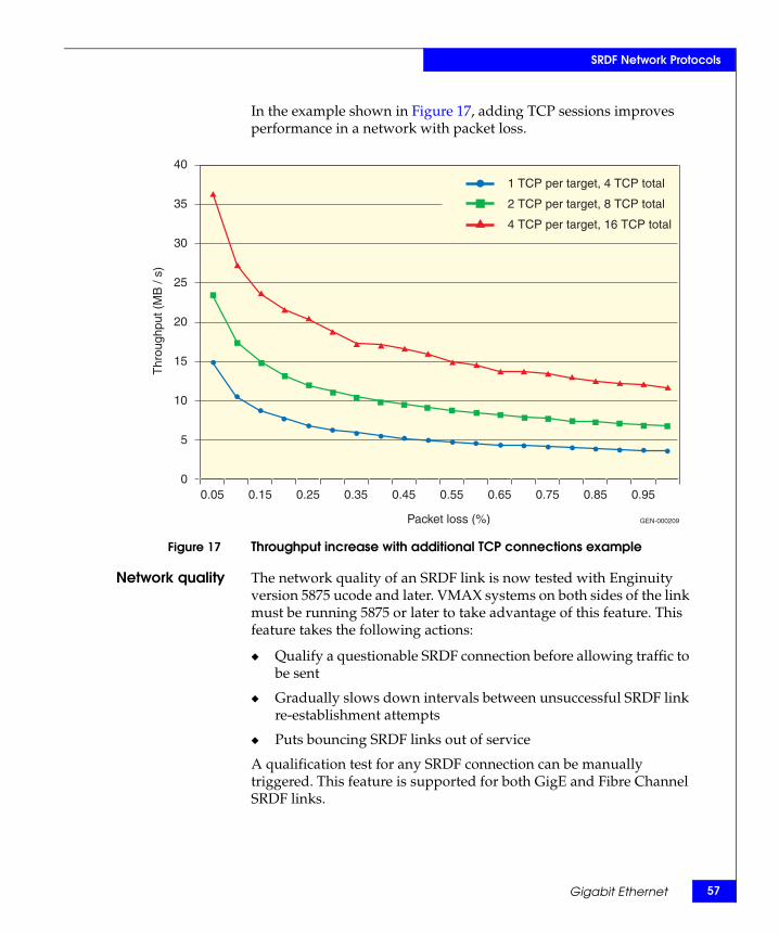
SRDF Network Protocols
In the example shown in Figure 17, adding TCP sessions improves performance in a network with packet loss.
Figure 17 Throughput increase with additional TCP connections example
Network quality The network quality of an SRDF link is now tested with Enginuity version 5875 ucode and later. VMAX systems on both sides of the link must be running 5875 or later to take advantage of this feature. This feature takes the following actions:
◆ Qualify a questionable SRDF connection before allowing traffic to be sent
◆ Gradually slows down intervals between unsuccessful SRDF link re-establishment attempts
◆ Puts bouncing SRDF links out of service
A qualification test for any SRDF connection can be manually triggered. This feature is supported for both GigE and Fibre Channel SRDF links.
Packet loss (%)
Thr
ough
put (
MB
/ s)
0.05 0.15 0.25 0.35 0.45 0.55 0.65 0.75 0.85 0.95
40
35
30
25
20
15
10
5
0
1 TCP per target, 4 TCP total
2 TCP per target, 8 TCP total
4 TCP per target, 16 TCP total
GEN-000209
Gigabit Ethernet 57
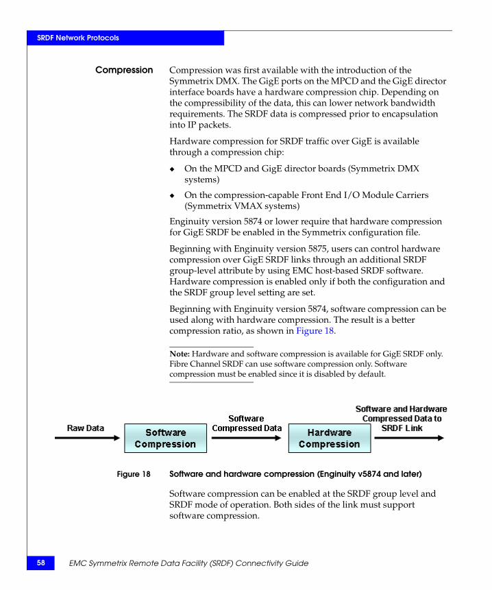
58
SRDF Network Protocols
Compression Compression was first available with the introduction of the Symmetrix DMX. The GigE ports on the MPCD and the GigE director interface boards have a hardware compression chip. Depending on the compressibility of the data, this can lower network bandwidth requirements. The SRDF data is compressed prior to encapsulation into IP packets.
Hardware compression for SRDF traffic over GigE is available through a compression chip:
◆ On the MPCD and GigE director boards (Symmetrix DMX systems)
◆ On the compression-capable Front End I/O Module Carriers (Symmetrix VMAX systems)
Enginuity version 5874 or lower require that hardware compression for GigE SRDF be enabled in the Symmetrix configuration file.
Beginning with Enginuity version 5875, users can control hardware compression over GigE SRDF links through an additional SRDF group-level attribute by using EMC host-based SRDF software. Hardware compression is enabled only if both the configuration and the SRDF group level setting are set.
Beginning with Enginuity version 5874, software compression can be used along with hardware compression. The result is a better compression ratio, as shown in Figure 18.
Note: Hardware and software compression is available for GigE SRDF only. Fibre Channel SRDF can use software compression only. Software compression must be enabled since it is disabled by default.
Figure 18 Software and hardware compression (Enginuity v5874 and later)
Software compression can be enabled at the SRDF group level and SRDF mode of operation. Both sides of the link must support software compression.
EMC Symmetrix Remote Data Facility (SRDF) Connectivity Guide
SRDF Network Protocols
Note: Higher host response times can result due to the software compression. If host response time is not a concern, bandwidth savings can be realized through the additional software compression.
Security IPsec (Internet Protocol Security) and IPv6 are available on the GigE/IPsec Multiprotocol Channel Director beginning with Enginuity version 5773 microcode. The embedded line-grade encryption co-processor for this director provides strong security without degrading performance. Pre-shared encryption keys simplify management while maintaining security for data in transit.
These directors can co-exist in the same system with any existing DMX-4 channel directors. With the new director, IPsec can be enabled on a port-by-port basis. The IP stack version can be similarly configured per port.
The number of IPsec sessions are limited to 100 per port. IPsec enabled and IPsec disabled channel directors can co-exist in the same Symmetrix.
The GigE/IPsec channel director contains an embedded line-grade encryption co-processor to enable IP Security (IPsec) for SDRF-over-IP connections. IPsec and IPv6 capabilities will be configured via Symmetrix Management Console (SMC) or by EMC via the Service Processor. Status and configuration can also be monitored and viewed with SYMCLI commands.
The benefits of this director are as follows:
◆ Reduce the security risks associated with transmitting data over IP networks.
◆ Symmetrix-native encryption hardware eliminates the need for encryption appliances, reducing cost and complexity.
◆ Allows customers to effectively manage Symmetrix communication and encryption with one interface – Symmetrix Management Console (SMC).
◆ Addresses government and corporate mandates for IPv6 capable products.
◆ Support for the industry-leading AES 256, AES 128, and 3DES encryption algorithms.
For additional details on IPsec configuration and encryption, refer to the Symmetrix 5773 GigE and Multiprotocol IPv4/6 Channel Directors Technical Note available on Powerlink.
Gigabit Ethernet 59
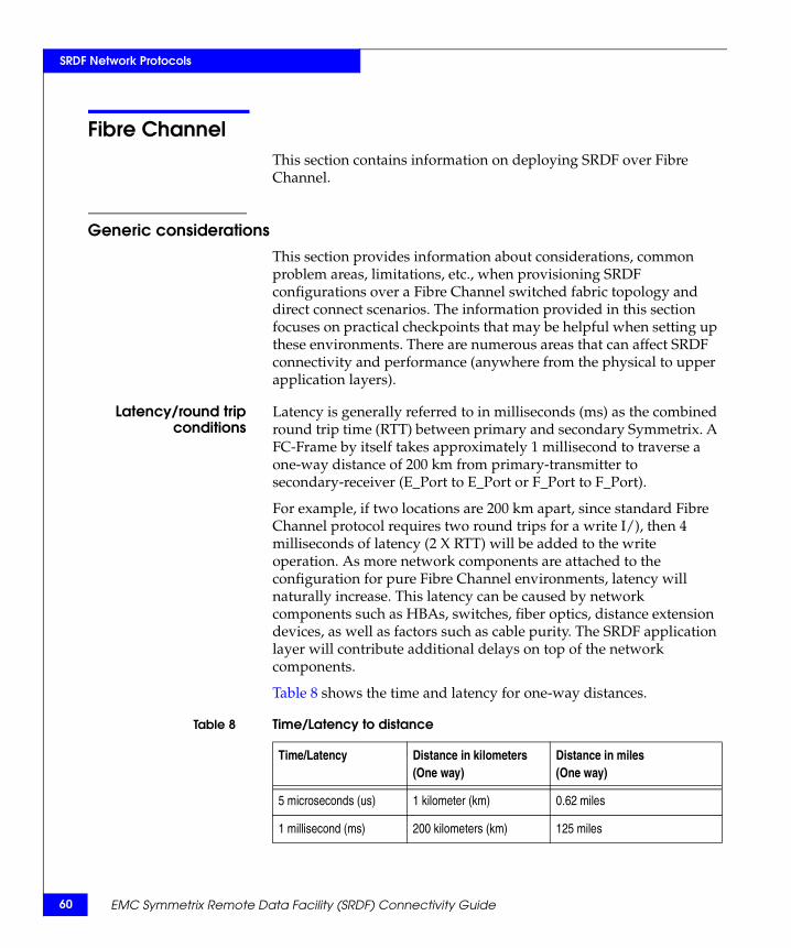
60
SRDF Network Protocols
Fibre ChannelThis section contains information on deploying SRDF over Fibre Channel.
Generic considerations
This section provides information about considerations, common problem areas, limitations, etc., when provisioning SRDF configurations over a Fibre Channel switched fabric topology and direct connect scenarios. The information provided in this section focuses on practical checkpoints that may be helpful when setting up these environments. There are numerous areas that can affect SRDF connectivity and performance (anywhere from the physical to upper application layers).
Latency/round tripconditions
Latency is generally referred to in milliseconds (ms) as the combined round trip time (RTT) between primary and secondary Symmetrix. A FC-Frame by itself takes approximately 1 millisecond to traverse a one-way distance of 200 km from primary-transmitter to secondary-receiver (E_Port to E_Port or F_Port to F_Port).
For example, if two locations are 200 km apart, since standard Fibre Channel protocol requires two round trips for a write I/), then 4 milliseconds of latency (2 X RTT) will be added to the write operation. As more network components are attached to the configuration for pure Fibre Channel environments, latency will naturally increase. This latency can be caused by network components such as HBAs, switches, fiber optics, distance extension devices, as well as factors such as cable purity. The SRDF application layer will contribute additional delays on top of the network components.
Table 8 shows the time and latency for one-way distances.
Table 8 Time/Latency to distance
Time/Latency Distance in kilometers (One way)
Distance in miles(One way)
5 microseconds (us) 1 kilometer (km) 0.62 miles
1 millisecond (ms) 200 kilometers (km) 125 miles
EMC Symmetrix Remote Data Facility (SRDF) Connectivity Guide
SRDF Network Protocols
Using Symmetrix tools (inlines, symcli, Symmetrix Management Console, etc.) or external performance monitoring tools, the round trip time can be determined for troubleshooting any SRDF latency issues within the Fibre Channel network.
BB_Credits Fibre Channel uses the BB_Credits (Buffer-to-Buffer Credits) mechanism for hardware-based flow control. This means that a port has the ability to pace the frame flow into its processing buffers. This mechanism eliminates the need of switching hardware to discard frames due to high congestion. EMC testing has shown this mechanism to be extremely effective in its speed and robustness.
BB_Credit management occurs between any two Fibre Channel ports that are connected. For example:
◆ One N_Port and one F_Port
◆ Two E_Ports
◆ Two N_Ports in a point-to-point topology
The standard provides a frame-acknowledgement mechanism in which an R_RDY (Receiver Ready) primitive is sent from the receiving port to the transmitting port for every available buffer on the receiving side. The transmitting port maintains a count of free receiver buffers, and will continue to send frames if the count is greater than zero.
The algorithm is as follows:
1. The transmitter's count initializes to the BB_Credit value established when the ports exchange parameters at login.
2. The transmitting port decrements the count per transmitted frame.
3. The transmitting port increments the count per R_RDY it receives from the receiving port.
Fibre Channel 61
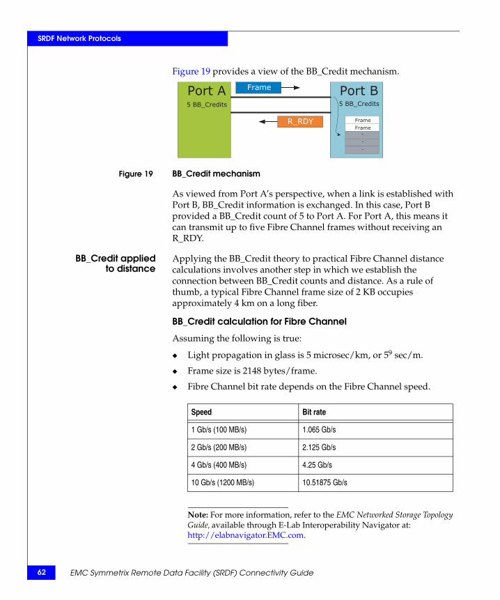
62
SRDF Network Protocols
Figure 19 provides a view of the BB_Credit mechanism.
Figure 19 BB_Credit mechanism
As viewed from Port A’s perspective, when a link is established with Port B, BB_Credit information is exchanged. In this case, Port B provided a BB_Credit count of 5 to Port A. For Port A, this means it can transmit up to five Fibre Channel frames without receiving an R_RDY.
BB_Credit appliedto distance
Applying the BB_Credit theory to practical Fibre Channel distance calculations involves another step in which we establish the connection between BB_Credit counts and distance. As a rule of thumb, a typical Fibre Channel frame size of 2 KB occupies approximately 4 km on a long fiber.
BB_Credit calculation for Fibre Channel
Assuming the following is true:
◆ Light propagation in glass is 5 microsec/km, or 59 sec/m.
◆ Frame size is 2148 bytes/frame.
◆ Fibre Channel bit rate depends on the Fibre Channel speed.
Note: For more information, refer to the EMC Networked Storage Topology Guide, available through E-Lab Interoperability Navigator at: http://elabnavigator.EMC.com.
Port BFrame
R_RDY
5 BB_Credits
Frame
Frame-
-
-
Port A5 BB_Credits
Speed Bit rate
1 Gb/s (100 MB/s) 1.065 Gb/s
2 Gb/s (200 MB/s) 2.125 Gb/s
4 Gb/s (400 MB/s) 4.25 Gb/s
10 Gb/s (1200 MB/s) 10.51875 Gb/s
EMC Symmetrix Remote Data Facility (SRDF) Connectivity Guide
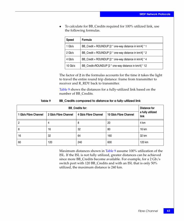
SRDF Network Protocols
◆ To calculate for BB_Credits required for 100% utilized link, use the following formulas.
The factor of 2 in the formulas accounts for the time it takes the light to travel the entire round trip distance: frame from transmitter to receiver and R_RDY back to transmitter.
Table 9 shows the distances for a fully-utilized link based on the number of BB_Credits.
Maximum distances shown in Table 9 assume 100% utilization of the ISL. If the ISL is not fully utilized, greater distances can be achieved since more BB_Credits become available. For example, for a 2 Gb/s switch port with 120 BB_Credits and with an ISL that is only 50% utilized, the maximum distance is 240 km.
Speed Formula
1 Gb/s BB_Credit = ROUNDUP [2 * one-way distance in km/4] * 1
2 Gb/s BB_Credit = ROUNDUP [2 * one-way distance in km/4] * 2
4 Gb/s BB_Credit = ROUNDUP [2 * one-way distance in km/4] * 4
10 Gb/s BB_Credit=ROUNDUP [2 * one-way distance in km/4] * 12
Table 9 BB_Credits compared to distance for a fully-utilized link
BB_Credits for: Distance for a fully utilized link1 Gb/s Fibre Channel 2 Gb/s Fibre Channel 4 Gb/s Fibre Channel 10 Gb/s Fibre Channel
2 4 8 20 4 km
8 16 32 80 16 km
16 32 64 160 32 km
60 120 240 600 120 km
Fibre Channel 63
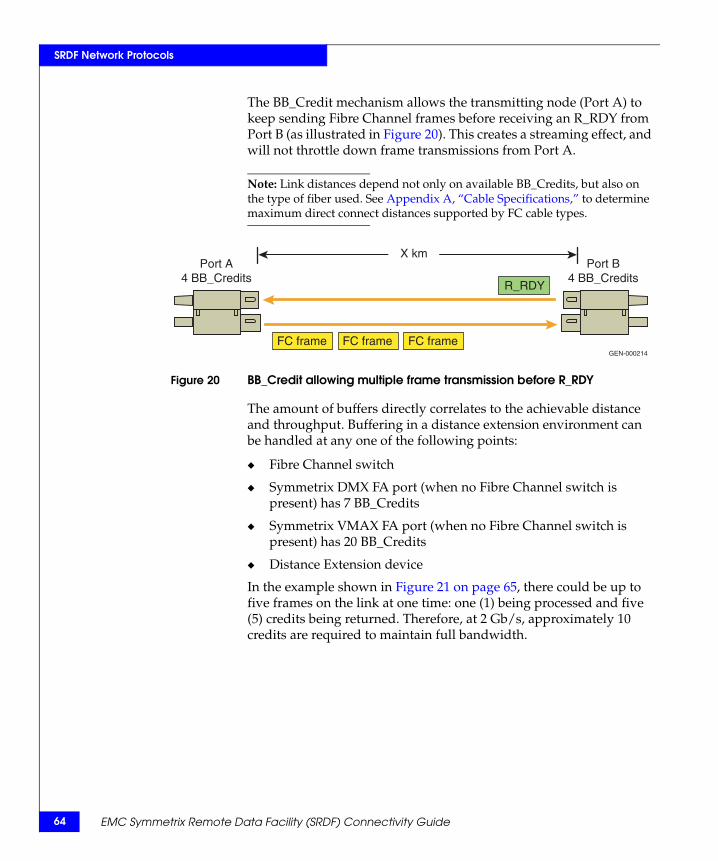
64
SRDF Network Protocols
The BB_Credit mechanism allows the transmitting node (Port A) to keep sending Fibre Channel frames before receiving an R_RDY from Port B (as illustrated in Figure 20). This creates a streaming effect, and will not throttle down frame transmissions from Port A.
Note: Link distances depend not only on available BB_Credits, but also on the type of fiber used. See Appendix A, “Cable Specifications,” to determine maximum direct connect distances supported by FC cable types.
Figure 20 BB_Credit allowing multiple frame transmission before R_RDY
The amount of buffers directly correlates to the achievable distance and throughput. Buffering in a distance extension environment can be handled at any one of the following points:
◆ Fibre Channel switch
◆ Symmetrix DMX FA port (when no Fibre Channel switch is present) has 7 BB_Credits
◆ Symmetrix VMAX FA port (when no Fibre Channel switch is present) has 20 BB_Credits
◆ Distance Extension device
In the example shown in Figure 21 on page 65, there could be up to five frames on the link at one time: one (1) being processed and five (5) credits being returned. Therefore, at 2 Gb/s, approximately 10 credits are required to maintain full bandwidth.
FC frame FC frame FC frame
R_RDY
X kmPort A
4 BB_CreditsPort B
4 BB_Credits
GEN-000214
EMC Symmetrix Remote Data Facility (SRDF) Connectivity Guide
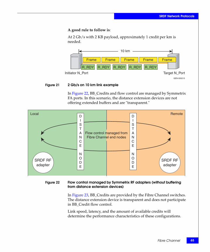
SRDF Network Protocols
A good rule to follow is:
At 2 Gb/s with 2 KB payload, approximately 1 credit per km is needed.
Figure 21 2 Gb/s on 10 km link example
In Figure 22, BB_Credits and flow control are managed by Symmetrix FA ports. In this scenario, the distance extension devices are not offering extended buffers and are "transparent."
Figure 22 Flow control managed by Symmetrix RF adapters (without buffering from distance extension devices)
In Figure 23, BB_Credits are provided by the Fibre Channel switches. The distance extension device is transparent and does not participate in BB_Credit flow control.
Link speed, latency, and the amount of available credits will determine the performance characteristics of these configurations.
Frame Frame Frame Frame
10 km
GEN-000215
Frame
R_RDY R_RDY R_RDY R_RDY R_RDY
Initiator N_Port Target N_Port
SRDF RFadapter
SRDF RFadapter
DISTANCE
NODE
DISTANCE
NODE
Local Remote
Flow control managed fromFibre Channel end nodes
Fibre Channel 65
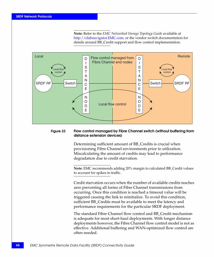
66
SRDF Network Protocols
Note: Refer to the EMC Networked Storage Topology Guide available at http://elabnavigator.EMC.com, or the vendor switch documentation for details around BB_Credit support and flow control implementation.
Figure 23 Flow control managed by Fibre Channel switch (without buffering from distance extension devices)
Determining sufficient amount of BB_Credits is crucial when provisioning Fibre Channel environments prior to utilization. Miscalculating the amount of credits may lead to performance degradation due to credit starvation.
Note: EMC recommends adding 20% margin to calculated BB_Credit values to account for spikes in traffic.
Credit starvation occurs when the number of available credits reaches zero preventing all forms of Fibre Channel transmissions from occurring. Once this condition is reached a timeout value will be triggered causing the link to reinitialize. To avoid this condition, sufficient BB_Credits must be available to meet the latency and performance requirements for the particular SRDF deployment.
The standard Fibre Channel flow control and BB_Credit mechanism is adequate for most short-haul deployments. With longer distance deployments however, the Fibre Channel flow control model is not as effective. Additional buffering and WAN-optimized flow control are often needed.
SRDF RF SRDF RF
DISTANCE
NODE
DISTANCE
NODE
Switch
Local flowcontrol
Switch
Local flowcontrol
Local RemoteFlow control managed fromFibre Channel end nodes
Local flow control
EMC Symmetrix Remote Data Facility (SRDF) Connectivity Guide
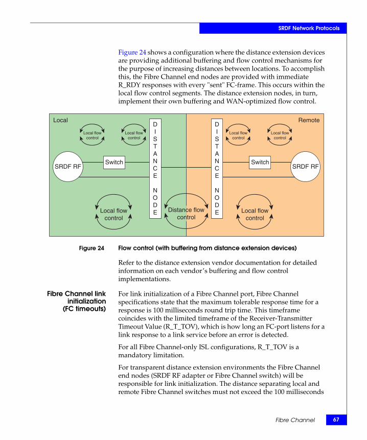
SRDF Network Protocols
Figure 24 shows a configuration where the distance extension devices are providing additional buffering and flow control mechanisms for the purpose of increasing distances between locations. To accomplish this, the Fibre Channel end nodes are provided with immediate R_RDY responses with every "sent" FC-frame. This occurs within the local flow control segments. The distance extension nodes, in turn, implement their own buffering and WAN-optimized flow control.
Figure 24 Flow control (with buffering from distance extension devices)
Refer to the distance extension vendor documentation for detailed information on each vendor’s buffering and flow control implementations.
Fibre Channel linkinitialization
(FC timeouts)
For link initialization of a Fibre Channel port, Fibre Channel specifications state that the maximum tolerable response time for a response is 100 milliseconds round trip time. This timeframe coincides with the limited timeframe of the Receiver-Transmitter Timeout Value (R_T_TOV), which is how long an FC-port listens for a link response to a link service before an error is detected.
For all Fibre Channel-only ISL configurations, R_T_TOV is a mandatory limitation.
For transparent distance extension environments the Fibre Channel end nodes (SRDF RF adapter or Fibre Channel switch) will be responsible for link initialization. The distance separating local and remote Fibre Channel switches must not exceed the 100 milliseconds
SRDF RF SRDF RF
DISTANCE
NODE
DISTANCE
NODELocal flow
controlLocal flow
controlDistance flow
control
Switch
Local flowcontrol
Local flowcontrol
Switch
Local flowcontrol
Local flowcontrol
Local Remote
Fibre Channel 67
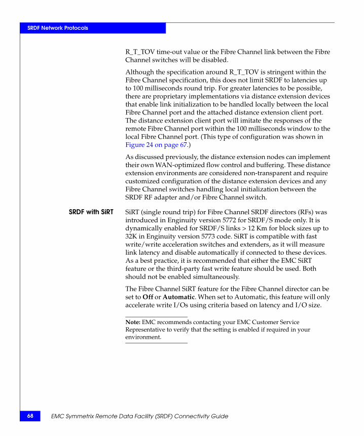
68
SRDF Network Protocols
R_T_TOV time-out value or the Fibre Channel link between the Fibre Channel switches will be disabled.
Although the specification around R_T_TOV is stringent within the Fibre Channel specification, this does not limit SRDF to latencies up to 100 milliseconds round trip. For greater latencies to be possible, there are proprietary implementations via distance extension devices that enable link initialization to be handled locally between the local Fibre Channel port and the attached distance extension client port. The distance extension client port will imitate the responses of the remote Fibre Channel port within the 100 milliseconds window to the local Fibre Channel port. (This type of configuration was shown in Figure 24 on page 67.)
As discussed previously, the distance extension nodes can implement their own WAN-optimized flow control and buffering. These distance extension environments are considered non-transparent and require customized configuration of the distance extension devices and any Fibre Channel switches handling local initialization between the SRDF RF adapter and/or Fibre Channel switch.
SRDF with SiRT SiRT (single round trip) for Fibre Channel SRDF directors (RFs) was introduced in Enginuity version 5772 for SRDF/S mode only. It is dynamically enabled for SRDF/S links > 12 Km for block sizes up to 32K in Enginuity version 5773 code. SiRT is compatible with fast write/write acceleration switches and extenders, as it will measure link latency and disable automatically if connected to these devices. As a best practice, it is recommended that either the EMC SiRT feature or the third-party fast write feature should be used. Both should not be enabled simultaneously.
The Fibre Channel SiRT feature for the Fibre Channel director can be set to Off or Automatic. When set to Automatic, this feature will only accelerate write I/Os using criteria based on latency and I/O size.
Note: EMC recommends contacting your EMC Customer Service Representative to verify that the setting is enabled if required in your environment.
EMC Symmetrix Remote Data Facility (SRDF) Connectivity Guide
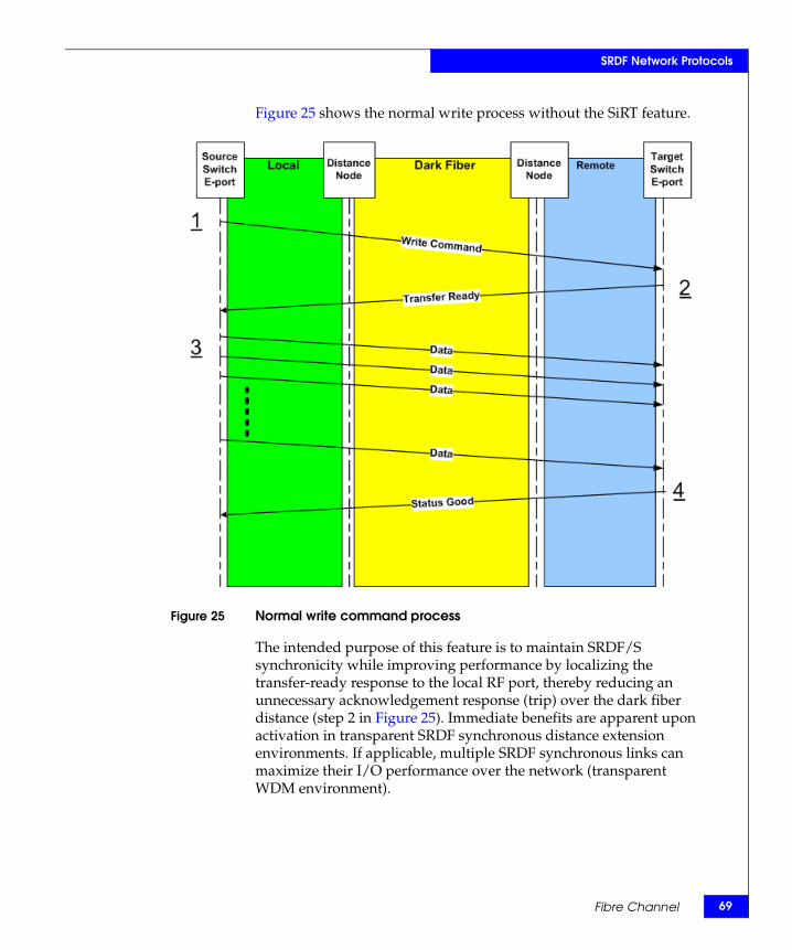
SRDF Network Protocols
Figure 25 shows the normal write process without the SiRT feature.
Figure 25 Normal write command process
The intended purpose of this feature is to maintain SRDF/S synchronicity while improving performance by localizing the transfer-ready response to the local RF port, thereby reducing an unnecessary acknowledgement response (trip) over the dark fiber distance (step 2 in Figure 25). Immediate benefits are apparent upon activation in transparent SRDF synchronous distance extension environments. If applicable, multiple SRDF synchronous links can maximize their I/O performance over the network (transparent WDM environment).
Fibre Channel 69
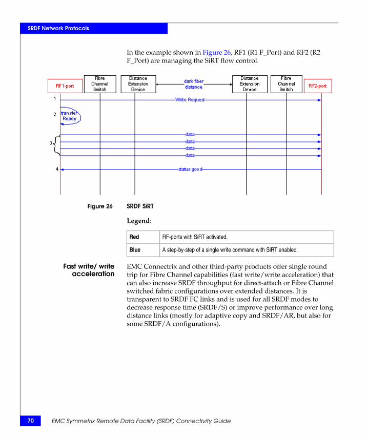
70
SRDF Network Protocols
In the example shown in Figure 26, RF1 (R1 F_Port) and RF2 (R2 F_Port) are managing the SiRT flow control.
Figure 26 SRDF SiRT
Legend:
Fast write/ writeacceleration
EMC Connectrix and other third-party products offer single round trip for Fibre Channel capabilities (fast write/write acceleration) that can also increase SRDF throughput for direct-attach or Fibre Channel switched fabric configurations over extended distances. It is transparent to SRDF FC links and is used for all SRDF modes to decrease response time (SRDF/S) or improve performance over long distance links (mostly for adaptive copy and SRDF/AR, but also for some SRDF/A configurations).
Red RF-ports with SiRT activated.
Blue A step-by-step of a single write command with SiRT enabled.
EMC Symmetrix Remote Data Facility (SRDF) Connectivity Guide
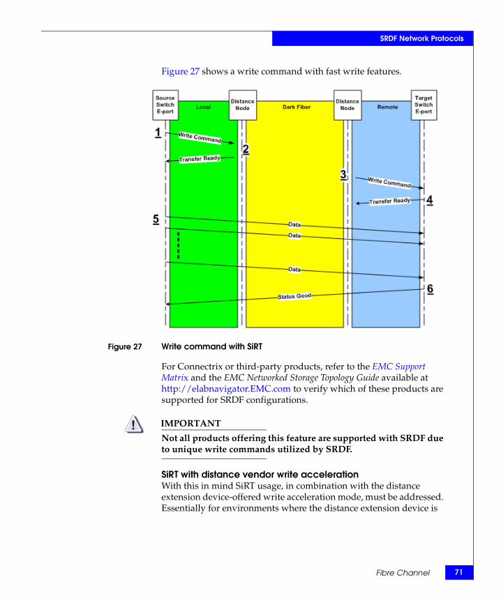
SRDF Network Protocols
Figure 27 shows a write command with fast write features.
Figure 27 Write command with SiRT
For Connectrix or third-party products, refer to the EMC Support Matrix and the EMC Networked Storage Topology Guide available at http://elabnavigator.EMC.com to verify which of these products are supported for SRDF configurations.
IMPORTANT!Not all products offering this feature are supported with SRDF due to unique write commands utilized by SRDF.
SiRT with distance vendor write acceleration With this in mind SiRT usage, in combination with the distance extension device-offered write acceleration mode, must be addressed. Essentially for environments where the distance extension device is
Fibre Channel 71
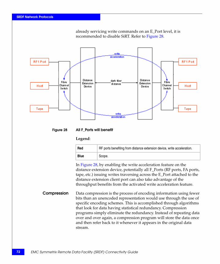
72
SRDF Network Protocols
already servicing write commands on an E_Port level, it is recommended to disable SiRT. Refer to Figure 28.
Figure 28 All F_Ports will benefit
Legend:
In Figure 28, by enabling the write acceleration feature on the distance extension device, potentially all F_Ports (RF ports, FA ports, tape, etc.) issuing writes traversing across the E_Port attached to the distance extension client port can also take advantage of the throughput benefits from the activated write acceleration feature.
Compression Data compression is the process of encoding information using fewer bits than an unencoded representation would use through the use of specific encoding schemes. This is accomplished through algorithms that look for data having statistical redundancy. Compression programs simply eliminate the redundancy. Instead of repeating data over and over again, a compression program will store the data once and then refer back to it whenever it appears in the original data stream.
Red RF ports benefiting from distance extension device, write acceleration.
Blue Scope.
EMC Symmetrix Remote Data Facility (SRDF) Connectivity Guide
SRDF Network Protocols
Note: Hardware and software compression is available for GigE SRDF only. Fibre Channel SRDF can use software compression only. Software compression must be enabled since it is disabled by default.
Compression for Fibre Channel exists and is supported by EMC with various distance extension and switch products. Keep in mind the following characteristics:
◆ Software compression is typically a lower cost option suited more for lower bandwidth environments (for example, OC-3).
◆ Efficiency of the compression is dependent on the algorithms used and the compressibility of the data (random versus sequential).
◆ Compression is not recommended where the available bandwidth meets or exceeds the throughput requirements.
Encryption Encryption devices can be used to ensure the secrecy of data transmitted between two points. Encryption refers to algorithmic schemes that encode plain text into nonreadable form or cyphertext. Currently, there are no supported solutions that encrypt native Fibre Channel data inflight. Encryption must therefore occur on the WAN using either IP or SONET/SDH encryption devices.
Forward error control Forward error correction has been widely deployed at the physical-link layer to check for and correct bit errors on WAN links. Even when a network's physical link is free from bit errors, packets may still get dropped in transit on WAN links because of congestion.
Packet-level forward error control (FEC) is an error control technique available with some distance extension devices where additional packets are inserted within the data stream that allow for reconstruction of data (if corrupted) without the need for retransmission. Retransmissions, especially with synchronous SRDF, can be extremely costly and should be avoided whenever possible.
Fabric isolation Fabric isolation is a method to bound fabric definition. Boundaries can be defined functionally or geographically. The goal is to define the fabrics in such a way that events (such as network problems, administrative configurations changes, or hardware issues) occurring in one fabric will not impact other fabrics. The challenge with isolated fabrics is how to share resources amongst the fabrics.
Fibre Channel 73
74
SRDF Network Protocols
In distance extension networks, isolating traffic locally while minimizing traffic across the WAN leads to SRDF deployments which are higher performing and less problematic.
Fabric isolation can be achieved in one of the following ways, each discussed in this section:
◆ “Dedicated fabrics,” next
◆ “VSAN” on page 74
◆ “FC routing” on page 75
Dedicated fabrics
Isolation between fabrics can be achieved by using dedicated switches to form the link across the WAN. In a typical scenario each site (local and remote) will have its operational fabric where hosts access storage. A third fabric is created for traffic across the WAN. The WAN fabric will not be connected to the local and remote operational fabrics.
Disadvantages of this method include the need for additional hardware and the inability to share resources between the local and remote sites.
VSAN
Virtual SAN (VSAN) is used to allocate ports across different physical switches to create a virtual fabric. It acts as a self-contained fabric despite sharing hardware resources on a switch or multiple switches. Ports within a switch can be partitioned into multiple VSANs. In addition, multiple switches can join available ports to form a single VSAN. VSAN contains dedicated fabric services designed for enhanced scalability, resilience, and independence. This is especially useful in segregating service operations and failover events between high availability resources.
Each VSAN contains its own complement of hardware-enforced zones, dedicated fabric services, and management capabilities, just as if the VSAN were configured as a separate physical fabric. Therefore, VSANs are designed to allow more efficient SAN utilization and flexibility.
VSAN provides the same advantages that a dedicated fabric provides, however, it eliminates the need for additional hardware. Resource sharing between VSANs can be accomplished by using the Inter-VSAN Routing (IVR) feature.
EMC Symmetrix Remote Data Facility (SRDF) Connectivity Guide
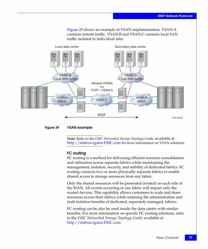
SRDF Network Protocols
Figure 29 shows an example of VSAN implementation. VSAN:A contains remote traffic. VSAN:B and VSAN:C contains local SAN traffic isolated to individual sites.
Figure 29 VSAN example
Note: Refer to the EMC Networked Storage Topology Guide, available at http://elabnavigator.EMC.com for more information on VSAN solutions.
FC routingFC routing is a method for delivering efficient resource consolidation and utilization across separate fabrics while maintaining the management, isolation, security, and stability of dedicated fabrics. FC routing connects two or more physically separate fabrics to enable shared access to storage resources from any fabric.
Only the shared resources will be presented (routed) on each side of the WAN. All events occurring in one fabric will impact only the routed devices. This capability allows customers to scale and share resources across their fabrics while retaining the administration and fault isolation benefits of dedicated, separately managed, fabrics.
FC routing can be also be used inside the data center with similar benefits. For more information on specific FC routing solutions, refer to the EMC Networked Storage Topology Guide, available at http://elabnavigator.EMC.com.
VSAN: BLocal SAN traffic
VSAN: CLocal SAN traffic
Allowed VSANson
FCIP = VSAN:A
VSAN:ASRDF VSAN:A
VSAN:ASRDF
SRDF
Local data center Secondary data center
SYM-002507
Fibre Channel 75
76
SRDF Network Protocols
Fibre Channel director considerationsThis section provides information to consider.
SRDFflow control
In addition to the Fibre Channel mechanisms and restrictions, SRDF flow control can be governed by the SRDF Flow Control Algorithm which allocates the number of I/Os that can be sent from the SRDF layer. This feature, introduced for SRDF over Fibre Channel in Enginuity version 5671, should be enabled for all extended distance asynchronous links (SRDF/A, SRDF/AR, and Adaptive Copy).It should not be used for SRDF/S and is disabled by default.
The SRDF algorithm first tracks, analyzes, and monitors for certain I/O conditions. It then determines the optimal number of I/Os (jobs) to send out on the SRDF links, based on certain RTT windows: 0-40ms; 40-120ms; and over 120ms. The algorithm maintains a manageable number of I/Os (job queues) while making efforts to avoid time-out scenarios. The Fibre Channel flow control is managed from the primary (sending) side of the SRDF Fibre Channel (RF) links, based on "activity" of each of the secondary ports, and monitoring for primary-side "resource shortage" reported by the Fibre Channel link hardware.
Network quality The network quality of an SRDF link is now tested with Enginuity version 5875 ucode and later. VMAX systems on both sides of the link must be running 5875 or later to take advantage of this feature. This feature takes the following actions:
◆ Qualify a questionable SRDF connection before allowing traffic to be sent
◆ Gradually slows down intervals between unsuccessful SRDF link re-establishment attempts
◆ Puts bouncing SRDF links out of service
A qualification test for any SRDF connection can be manually triggered. This feature is supported for both GigE and Fibre Channel SRDF links.
Compression Beginning with Enginuity version 5874, software compression is available with the Fibre Channel port. Software compression can be enabled at the SRDF group level and SRDF mode of operation. Both sides of the link must support software compression.
EMC Symmetrix Remote Data Facility (SRDF) Connectivity Guide
SRDF Network Protocols
Note: Hardware and software compression is available for GigE SRDF only. Fibre Channel SRDF can use software compression only. Software compression must be enabled since it is disabled by default.
IMPORTANT!Software compression should be disabled when Write Acceleration is enabled on an external Fibre Channel switch.
Note: Higher host response times can result due to the software compression. If host response time is not a concern, bandwidth savings can be realized.
FCIP and iFCP
FCIP FCIP is a tunneling protocol that transports Fibre Channel ISL traffic. FCIP uses IP as the transport protocol. An FCIP link tunnels all SRDF traffic between locations and may have one or more TCP connections between a pair of IP nodes for the tunnel end-points. From the Fibre Channel fabric view, an FCIP link is an ISL transporting all Fibre Channel control and data frames between switches, with the IP network and protocols transparent. One can configure one or more ISLs between Fibre Channel switches using FCIP links.
Proper network design is required given the speed and bandwidth differences between Fibre Channel and a typical IP network. This design should take into consideration the management of congestion and overload conditions. Fibre Channel fabrics connected via FCIP links are not isolated unless isolation is achieved using one of the fabric isolation methods mention earlier.
iFCP iFCP is a gateway-to-gateway protocol to provide communication over IP between two Fibre Channel end-devices residing in two different fabrics. An iFCP session is created between a pair of iFCP supporting devices for each pair of Fibre Channel devices. An iFCP gateway transports Fibre Channel device-to-device frames over TCP. An iFCP session uses a TCP connection for transport and IPsec for security, and manages Fibre Channel frame transport, data integrity, address translation, and session management for a pair of Fibre Channel devices. Since an iFCP gateway handles the communications between a pair of Fibre Channel devices, it only transports
Fibre Channel 77
78
SRDF Network Protocols
device-to-device frames over the session, and hence, the Fibre Channel fabrics across the session are fully isolated and independent.
While FCIP by itself does not provide fabric isolation, iFCP is a Fibre Channel routing protocol and benefits from all the advantages of fabric isolation and FC routing.
Note: Consult the Distance Extension Solution table of the EMC Support Matrix and the EMC Networked Storage Topology Guide, available at http://elabnavigator.EMC.com, for more details on supported FCIP and iFCP devices.
FC-SONET
This section provides information on FC-SONET and the Generic Framing Procedure (GFP).
Generic FramingProcedure
The Generic Framing Procedure (GFP) was originally developed for the purpose of encapsulating IP packets or Ethernet MAC frames into SONET. GFP is an efficient protocol that simplifies the mapping of user data into SONET frames.
GFP's importance to SRDF is that it provides simple encapsulation for native storage protocols while promising interoperability between any vendor’s GFP-compatible equipment.
GFP-T is a specific implementation of the protocol that "transparently" encapsulates any 8B/10B encoded frame into SONET packets for transport across the WAN. GFP-T can be used for transport of a wide range of protocols including ESCON, FICON, Fibre Channel, Gigabit Ethernet, HDTV and InfiniBand.
Using GFP-T, 8B/10B characters are decoded and re-encoded into a 64B/65B word. Eight of these words are then grouped together into an octet along with control and error flags. Eight octets are then assembled into a "superblock," which is scrambled and subject to cyclic redundancy checks. The resulting packet is fully SONET compatible.
Note: Refer to the Distance Extension Solution table of the EMC Support Matrix and the EMC Networked Storage Topology Guide, available at http://elabnavigator.EMC.com for more details on supported FC-SONET devices.
EMC Symmetrix Remote Data Facility (SRDF) Connectivity Guide
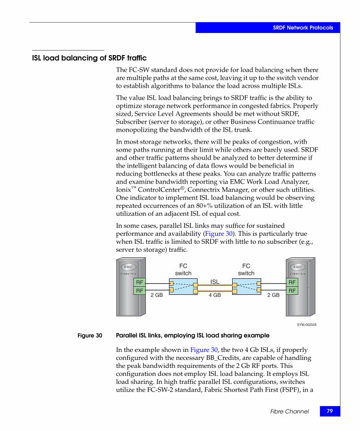
SRDF Network Protocols
ISL load balancing of SRDF traffic The FC-SW standard does not provide for load balancing when there are multiple paths at the same cost, leaving it up to the switch vendor to establish algorithms to balance the load across multiple ISLs.
The value ISL load balancing brings to SRDF traffic is the ability to optimize storage network performance in congested fabrics. Properly sized, Service Level Agreements should be met without SRDF, Subscriber (server to storage), or other Business Continuance traffic monopolizing the bandwidth of the ISL trunk.
In most storage networks, there will be peaks of congestion, with some paths running at their limit while others are barely used. SRDF and other traffic patterns should be analyzed to better determine if the intelligent balancing of data flows would be beneficial in reducing bottlenecks at these peaks. You can analyze traffic patterns and examine bandwidth reporting via EMC Work Load Analyzer, Ionix™ ControlCenter®, Connectrix Manager, or other such utilities. One indicator to implement ISL load balancing would be observing repeated occurrences of an 80+% utilization of an ISL with little utilization of an adjacent ISL of equal cost.
In some cases, parallel ISL links may suffice for sustained performance and availability (Figure 30). This is particularly true when ISL traffic is limited to SRDF with little to no subscriber (e.g., server to storage) traffic.
Figure 30 Parallel ISL links, employing ISL load sharing example
In the example shown in Figure 30, the two 4 Gb ISLs, if properly configured with the necessary BB_Credits, are capable of handling the peak bandwidth requirements of the 2 Gb RF ports. This configuration does not employ ISL load balancing. It employs ISL load sharing. In high traffic parallel ISL configurations, switches utilize the FC-SW-2 standard, Fabric Shortest Path First (FSPF), in a
SYM-002505
RF
RF
RF
RF2 GB 4 GB 2 GB
ISL
FCswitch
FCswitch
Fibre Channel 79
80
SRDF Network Protocols
round-robin method to share load amongst ISLs of equal cost. This is a static connection defined when the fabric is built. Adding more parallel ISL connections may reduce congestion, but this eventually leads to a more costly, inflexible method of load sharing. ISL load balancing provides a more efficient solution for an oversubscribed ISL.
Load balancing should also be implemented if any ISL is observed to be over-utilized while an adjacent ISL is minimally utilized. Implementing load balancing under either of these conditions will allow for a more intelligently balanced data path.
Figure 31 provides an example. In this case, the effective bandwidth is dynamically shared amongst both SRDF and other traffic. Ideally, the number of hops between RF and server N_Ports should be kept to one, and the fabric should be logically segregated between subscriber
EMC Symmetrix Remote Data Facility (SRDF) Connectivity Guide
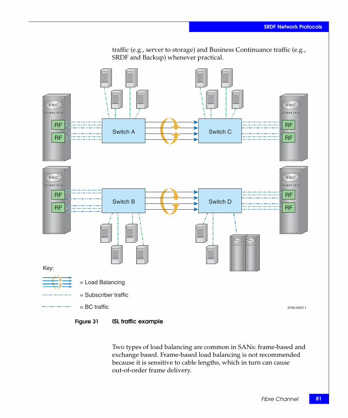
SRDF Network Protocols
traffic (e.g., server to storage) and Business Continuance traffic (e.g., SRDF and Backup) whenever practical.
Figure 31 ISL traffic example
Two types of load balancing are common in SANs: frame-based and exchange based. Frame-based load balancing is not recommended because it is sensitive to cable lengths, which in turn can cause out-of-order frame delivery.
Switch A
Switch B
Switch C
Switch D
RF
RF
RF
RF
RF
RF
RF
RF
SYM-002511
= Load Balancing
= Subscriber traffic
= BC traffic
Key:
Fibre Channel 81
82
SRDF Network Protocols
Since it is always a best practice to ensure enough ISLs to keep link utilization below 70%, it is recommended to always use exchange-based ISL load balancing for SRDF over distance to properly load balance and ensure no out-of-order frame delivery. Exchange-based load balancing is based on the SID, DID, and Fibre Channel originator exchange ID (OXID). Traffic is load balanced at the Fibre Channel exchange level where every exchange can take a different path through the fabric regardless of differences in cable length or latency. While SRDF can handle out-of-order frames and CRC errors via abort and retry algorithms, there can be substantial performance penalty in doing so. Monitoring Symmetrix error logs for high occurrences of BF2D, xx1E, and AB3E events is one method of determining if out-of-order and discarded frames are impacting performance. These events indicate that there are issues external to the Symmetrix.
Performanceand distance
considerations
Until recently, a delineating factor in EMC environments was the distance limitation of 200 km. Today, however, that has changed. For WDM, SONET, and SDH networks, the defining factor for distance supported in all cases depends on the following:
◆ Adherence to the R_T_TOV timer (defined as the latency between any two Fibre Channel N_Ports; cannot exceed 100 ms round trip)
Note: Third party distance extension devices may provide the ability for local Fibre Channel link initialization whereby the 100 ms (R_T_TOV) timer limitation may no longer be a limitation. For more details, refer to “Fibre Channel link initialization (FC timeouts)” on page 67.
◆ The specific tolerance of the customer application to increased latency
◆ Any additional buffering provided by SAN or distance equipment
◆ The distance the network equipment provider is capable of supporting
EMC Symmetrix Remote Data Facility (SRDF) Connectivity Guide
SRDF Network Protocols
ESCONSRDF over ESCON uses a Symmetrix RA director, which is basically an EA director configured to run SRDF emulation code.
RA directors employ an ESCON protocol schema, with one RA (RA1) in each connection assuming a role similar to a mainframe channel (host), and the other (RA2) assuming the role of a mainframe control unit (device). For this reason, significant protocol overhead is incurred in cases where a primary (R1) volume is configured to an RA2 director (bidirectional).
Connections in this environment may be through direct multimode cable connections between RA directors in Symmetrix systems up to 3 km apart. (Refer to Figure 32 on page 84.) For distance limitations regarding cable types for each cable segment, refer to Table 10 on page 120.
Each ESCON connection requires one pair of fiber-optic strands (xmit and rcv). RA directors can be used for SRDF through an ESCON director; however, the ESCON director ports must be configured to be static and dedicated. IBM ESCON Manager software may be used to control the ESCON director ports, but will present invalid status upon query operations to SRDF director ports.
Because ESCON directors provide their own transmit signals at each port, the effective distance of the overall 3 km link can be doubled. By using ESCON extender/repeater units or the ESCON director XDF feature, these distances can be extended up to 66 km for campus-mode SRDF. Distance extension devices, such as DWDM and ESCON over IP devices, can also be used to extend SRDF over ESCON links to hundreds, and even thousands, of kms.
Refer to the EMC Support Matrix and the EMC Networked Storage Topology Guide, available at http://elabnavigator.EMC.com, for more details on supported devices.
Note: For SRDF distances beyond 15 km, or connections via channel extenders, FarPoint™ mode should be used to eliminate distance limitations and minimize performance penalties.
ESCON 83
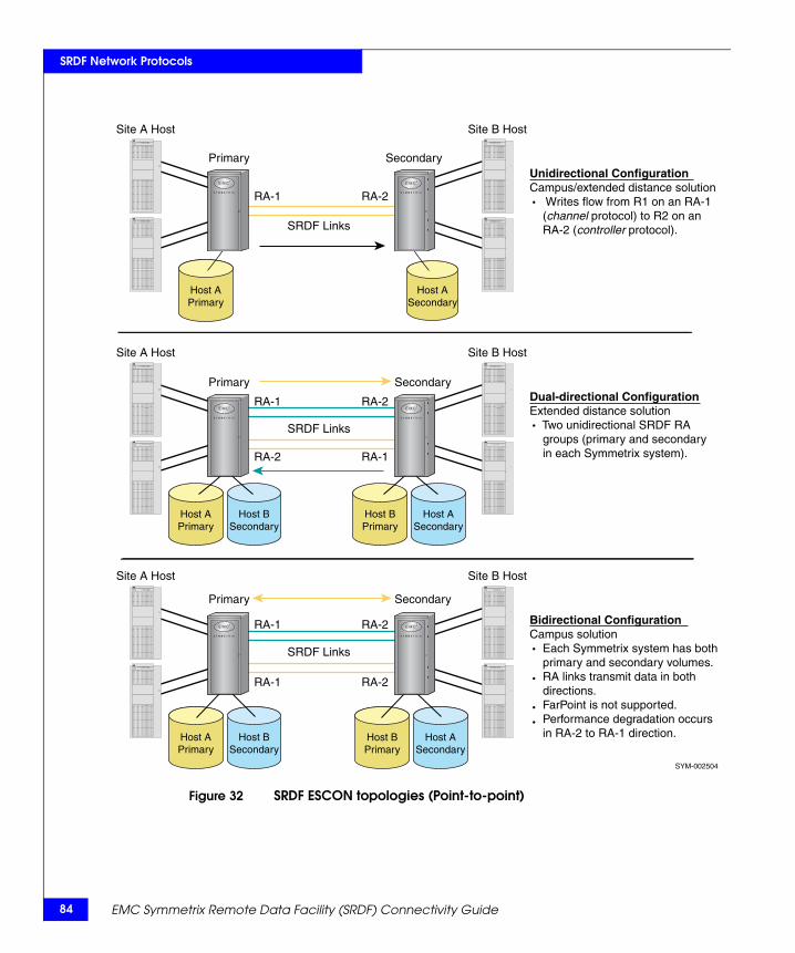
84
SRDF Network Protocols
Figure 32 SRDF ESCON topologies (Point-to-point)
Site B HostSite A Host
Site B Host
SYM-002504
Site A Host
RA-1 RA-2
RA-1 RA-2
SRDF Links
Primary Secondary
Bidirectional ConfigurationCampus solution Each Symmetrix system has both primary and secondary volumes. RA links transmit data in both directions. FarPoint is not supported. Performance degradation occurs in RA-2 to RA-1 direction.
Site B HostSite A Host
RA-1 RA-2
RA-2 RA-1
SRDF Links
Primary SecondaryDual-directional ConfigurationExtended distance solution Two unidirectional SRDF RA groups (primary and secondary in each Symmetrix system).
RA-1 RA-2
SRDF Links
Primary SecondaryUnidirectional ConfigurationCampus/extended distance solution Writes flow from R1 on an RA-1 (channel protocol) to R2 on an RA-2 (controller protocol).
Host APrimary
Host ASecondary
Host APrimary
Host BSecondary
Host BPrimary
Host ASecondary
Host BPrimary
Host ASecondary
Host APrimary
Host BSecondary
EMC Symmetrix Remote Data Facility (SRDF) Connectivity Guide
SRDF Network Protocols
FarPointFarPoint is an SRDF feature used only with ESCON extended distance solutions (and certain ESCON campus solutions) to optimize the performance of the SRDF links. This feature works by allowing each RA to transmit multiple I/Os, in series, over each SRDF link in pipeline fashion.
Standard SRDFwithout FarPoint
The standard ESCON SRDF protocol (without SRDF FarPoint) allows only one write I/O to occupy a communication link at a given time. The next write I/O occurs only after the remote Symmetrix system has acknowledged receipt of the previous I/O from the local Symmetrix system and an ending status is presented to the local Symmetrix system as shown in the top half of Figure 33 on page 86.
SRDF with FarPoint With SRDF FarPoint, a single remote adapter (R1) can serially transmit more than one write I/O over the SRDF links as shown in the bottom half of Figure 33. This method (referred to as pipelining) enables the SRDF communication links to be more fully utilized, depending on the distribution of application I/O write activity across multiple logical volumes. The number of write I/Os that can be placed on the link at one time is determined by the capacity of the type of SRDF link being used. With Enginuity version 5x67 or later, multiple copy tasks can be placed on the SRDF link for a single logical volume (up to eight per volume).
ESCON 85
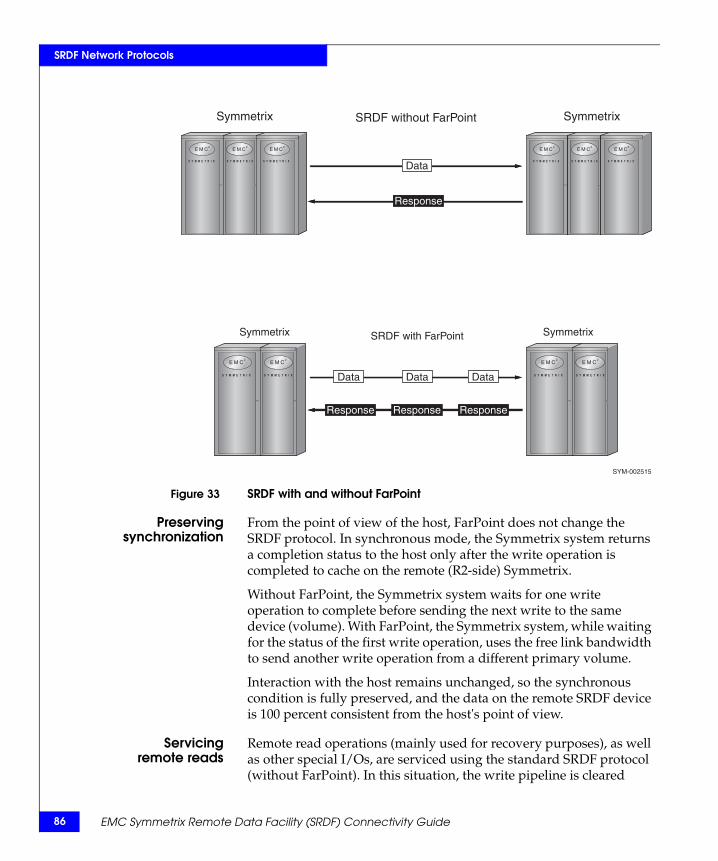
86
SRDF Network Protocols
Figure 33 SRDF with and without FarPoint
Preservingsynchronization
From the point of view of the host, FarPoint does not change the SRDF protocol. In synchronous mode, the Symmetrix system returns a completion status to the host only after the write operation is completed to cache on the remote (R2-side) Symmetrix.
Without FarPoint, the Symmetrix system waits for one write operation to complete before sending the next write to the same device (volume). With FarPoint, the Symmetrix system, while waiting for the status of the first write operation, uses the free link bandwidth to send another write operation from a different primary volume.
Interaction with the host remains unchanged, so the synchronous condition is fully preserved, and the data on the remote SRDF device is 100 percent consistent from the host's point of view.
Servicingremote reads
Remote read operations (mainly used for recovery purposes), as well as other special I/Os, are serviced using the standard SRDF protocol (without FarPoint). In this situation, the write pipeline is cleared
Symmetrix
SYM-002515
Symmetrix
Response
Data
DataDataData
Response Response Response
SRDF with FarPoint
Symmetrix SymmetrixSRDF without FarPoint
EMC Symmetrix Remote Data Facility (SRDF) Connectivity Guide
SRDF Network Protocols
before any read operations are performed. In other words, all FarPoint write I/Os in process on all the FarPoint-enabled RA links are completed, all links drop out of FarPoint to campus mode, and then the read I/O is completed.
Since FarPoint is uni-directional (not peer-to-peer protocol like Fibre Channel), any write from the RA2 back to the RA1 (a restore operation) is actually a requested read for the RA1 director on the R1 side of the link.
This entails 2 ½ round trips for each individual read I/O and since only one I/O is on the link at a time, the performance over distance degrades rapidly.
You should always swap R1/R2 and RA1/RA2 personalities to change the direction of FarPoint I/O before doing a restore/ ComeHome operation.
Performanceconsiderations
An SRDF configuration using FarPoint can improve performance substantially at the Symmetrix system level across a group of SRDF devices depending on the length of the SRDF links. Even on a short link, the FarPoint solution may provide some benefits due to the pipelining and one round trip per write.
However, write operations to a single device are still serialized by the host, so in the case of a synchronous device, a new write operation does not start until the previous write operation to that device receives a status from the remote system.
This means that the maximum number of write operations per device is still low, and using FarPoint in this situation does not improve system performance.
Note: The introduction of PAV/MA and striping does increase I/O concurrency at the volume level, potentially improving throughput in FarPoint configurations by having more active SRDF volumes.
ESCON 87

88
SRDF Network Protocols
EMC Symmetrix Remote Data Facility (SRDF) Connectivity Guide
4Invisible Body Tag
This chapter discusses various physical and transport options available for deploying SRDF networks using various metropolitan and wide-area topologies, and some best practices for deploying SRDF in these environment.
◆ Transport options ............................................................................... 90◆ Metro and WAN implementations .................................................. 97◆ WAN optimization........................................................................... 102◆ Best practices, recommendations, and considerations ............... 106
Network Topologiesand Implementations
Network Topologies and Implementations 89
90
Network Topologies and Implementations
Transport optionsThis section discusses the following transport options:
◆ “Dark fiber,” next
◆ “IP” on page 95
Dark fiberDark fiber is very expensive and in some cases, depending on the distance separating the sites, may be impractical for use as a WAN. Dark fiber is better suited for use in a metropolitan area network (MAN).
In cases where the distance is not an issue and large amounts of bandwidth are needed, dark fiber may be the best choice. Synchronous SRDF applications requiring high throughput and low latency are excellent candidates for DWDM/CWDM over dark fiber. For instance, SRDF/S configurations within Metropolitan Area Networks or MANs) are commonly deployed using Fibre Channel directors or switches with DWDM over dark fiber. Fibre Channel directors/switches typically support 60 - 255 BB_Credits, which is more than sufficient for SRDF/S distances.
Following are the various options available for dark fiber deployments, each discussed further in this section:
◆ “Long-wave optics,” next
◆ “CWDM” on page 91
◆ “DWDM” on page 91
◆ “SONET/SDH” on page 92
◆ “ATM” on page 94
◆ “T1/T3, E1/E3” on page 94
Long-wave optics Long-wave optics operating at the 1310nm wavelength are available for use with Symmetrix and Fibre Channel switches. As of the time of this writing, EMC offers various long-wave optics for Fibre Channel switches supporting distances of 10, 20, and 35 km. For Symmetrix RF cards, EMC offers a single long-wave optic capable of supporting 10 km.
EMC Symmetrix Remote Data Facility (SRDF) Connectivity Guide
Network Topologies and Implementations
When any of these optics are directly connected to dark fiber, only a single I/O stream can be driven across the fiber. If the customer's throughput requirements are satisfied through the use of these long-wave optics, this can be a viable solution.
CWDM Coarse Wave Division Multiplexing (CWDM) combines up to 16 wavelengths onto a single fiber. CWDM technology uses an ITU standard 20 nm spacing between the wavelengths, from 1310 nm to 1610 nm. With CWDM technology, since the wavelengths are relatively far apart (compared to DWDM), the lasers and transponders are generally inexpensive compared to DWDM.
Best practice is to use CWDM when:
◆ Customer's throughput requirements can be satisfied by the number of wavelengths available through CWDM.
◆ Cost of DWDM is prohibitive.
◆ Distance between locations is less than 100 km.
◆ Manageability requirements are met versus generally more robust management capabilities available with DWDM.
DWDM Dense Wave Division Multiplexing (DWDM) combines up to 160 wavelengths onto a single fiber. DWDM technology uses an ITU standard 0.8 nm spacing between the wavelengths with a reference frequency fixed at 1552.52 nm. With DWDM technology, the lasers and transponders are fairly expensive when compared to CWDM. Since wavelength spacing is so small, added components and controls are needed to maintain the precision of lasers.
Best practice is to use DWDM when:
◆ Customer has high throughput requirements that cannot be satisfied by CWDM.
◆ Distance between locations is greater than that supported by CWDM. DWDM systems can support distances separated by hundred's of kms through the use of high powered lasers and amplifiers.
◆ Manageability, in general, is more robust with DWDM systems. Therefore, if the customer requires high levels of manageability, DWDM systems should be considered.
Transport options 91
92
Network Topologies and Implementations
SONET/SDH SONET (Synchronous Optical Network) and SDH (Synchronous Digital Hierarchy) are a set of related standards for synchronous data transmission over fiber optic networks. SONET/SDH is the core backbone of all major ISPs, providing low latency, high availability, zero loss, and high bandwidth, all of which make it ideally suited for replicating large amounts of data over a WAN. SONET/SDH is also found in MANs and can be a suitable transport for lower bandwidth storage applications or for those customers without access to dark fiber.
SONET is the United States version of the standard published by the American National Standards Institute (ANSI). SDH is the international version of the standard published by the International Telecommunications Union (ITU).
SONET/SDH is not a communications protocol in and of itself, but rather a generic and all-purpose transport container for moving both voice and data. SONET/SDH can be used directly to support either ATM or Packet over SONET (PoS) networking.
The basic SONET/SDH signal operates at 51.840 Mb/s and is designated STS-1 (Synchronous Transport Signal one). The STS-1 frame is the basic unit of transmission in SONET/SDH. Higher speed circuits are formed by aggregating multiple STS-1 circuits. When sizing a network that will be using a SONET/SDH transport mechanism, make sure you take into account the overhead associated with SONET/SDH (see Table 11 on page 124).
Next generation SONET/SDH systems provide further enhancements through Generic Framing Procedure (GFP) and Virtual Concatenation (VCAT):
◆ GFP allows flexible multiplexing so that data from multiple clients sessions can be sent over the same link. GFP supports the transport of both packet-oriented (e.g., Ethernet, IP, etc.) and character-oriented (e.g., Fibre Channel) data. GFP is a framing procedure for mapping variable-length payloads into SONET/SDH synchronous-payload envelopes.
The value of GFP is it provides simple encapsulation for native data protocols (such as Ethernet or Fibre Channel) with extremely low overhead requirements (see Figure 34 on page 93). GFP mapping to SONET also promises interoperability by allowing any vendor’s GFP-compatible equipment to pass and offload GFP payloads.
EMC Symmetrix Remote Data Facility (SRDF) Connectivity Guide
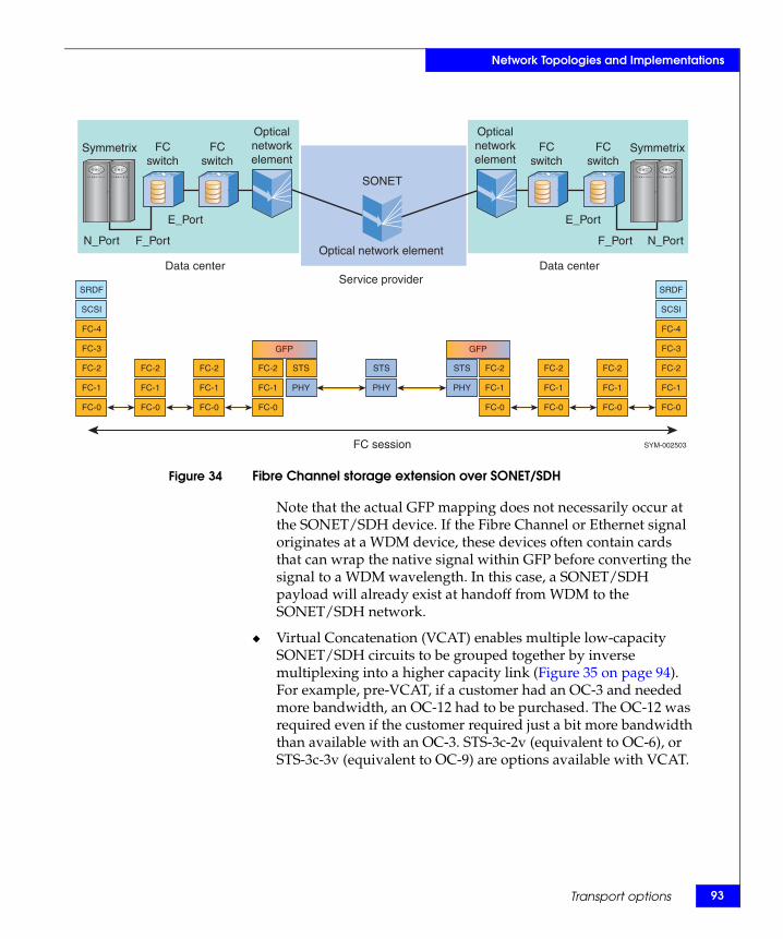
Network Topologies and Implementations
Figure 34 Fibre Channel storage extension over SONET/SDH
Note that the actual GFP mapping does not necessarily occur at the SONET/SDH device. If the Fibre Channel or Ethernet signal originates at a WDM device, these devices often contain cards that can wrap the native signal within GFP before converting the signal to a WDM wavelength. In this case, a SONET/SDH payload will already exist at handoff from WDM to the SONET/SDH network.
◆ Virtual Concatenation (VCAT) enables multiple low-capacity SONET/SDH circuits to be grouped together by inverse multiplexing into a higher capacity link (Figure 35 on page 94). For example, pre-VCAT, if a customer had an OC-3 and needed more bandwidth, an OC-12 had to be purchased. The OC-12 was required even if the customer required just a bit more bandwidth than available with an OC-3. STS-3c-2v (equivalent to OC-6), or STS-3c-3v (equivalent to OC-9) are options available with VCAT.
Symmetrix Symmetrix FC switch
FC switch
FC switch
FC switch
Data center Service provider
Data center
N_Port F_Port
E_Port
N_Port F_Port
E_Port
Optical network element
Optical network element
Optical network element
SONET
FC session
FC-0 FC-0 FC-0 FC-0
FC-1 FC-1 FC-1
FC-2 FC-2 FC-2
FC-1 FC-1 FC-1
FC-2 FC-2 FC-2
FC-1
FC-2
FC-3
FC-4
SCSI
SRDF
FC-1
FC-2
FC-3
FC-4
SCSI
SRDF
FC-0 FC-0 FC-0 FC-0
STS STS STS
PHY PHY PHY
SYM-002503
GFP GFP
Transport options 93
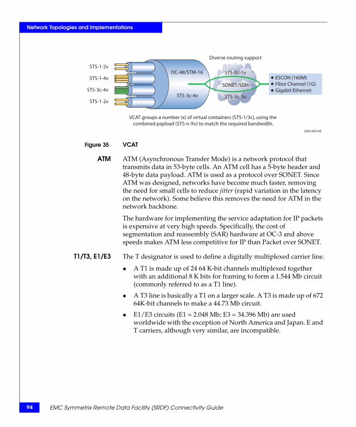
94
Network Topologies and Implementations
Figure 35 VCAT
ATM ATM (Asynchronous Transfer Mode) is a network protocol that transmits data in 53-byte cells. An ATM cell has a 5-byte header and 48-byte data payload. ATM is used as a protocol over SONET. Since ATM was designed, networks have become much faster, removing the need for small cells to reduce jitter (rapid variation in the latency on the network). Some believe this removes the need for ATM in the network backbone.
The hardware for implementing the service adaptation for IP packets is expensive at very high speeds. Specifically, the cost of segmentation and reassembly (SAR) hardware at OC-3 and above speeds makes ATM less competitive for IP than Packet over SONET.
T1/T3, E1/E3 The T designator is used to define a digitally multiplexed carrier line.
◆ A T1 is made up of 24 64 K-bit channels multiplexed together with an additional 8 K bits for framing to form a 1.544 Mb circuit (commonly referred to as a T1 line).
◆ A T3 line is basically a T1 on a larger scale. A T3 is made up of 672 64K-bit channels to make a 44.73 Mb circuit.
◆ E1/E3 circuits (E1 = 2.048 Mb; E3 = 34.396 Mb) are used worldwide with the exception of North America and Japan. E and T carriers, although very similar, are incompatible.
VCAT groups a number (x) of virtual containers (STS-1/3c), using thecombined payload (STS-n-Xv) to match the required bandwidth.
OC-48/STM-16
STS-3c-4v
Diverse routing support
STS-3c-1v
SONET/SDH
STS-3c-3v
ESCON (160M)Fibre Channel (1G)Gigabit Ethernet
STS-1-2v
STS-1-4v
STS-3c-4v
STS-1-2v
GEN-000140
EMC Symmetrix Remote Data Facility (SRDF) Connectivity Guide
Network Topologies and Implementations
CAUTION!T1s and E1s are not recommended for use with SRDF, except for ESCON FarPoint. It is possible to multiplex them together to get the minimum 10 Mb of bandwidth required for SRDF over Fibre Channel and GigE, but it is critical they be configured properly and are properly load-balanced so the packets do not arrive at the secondary side out of order.
IPThis section contains network considerations including, bandwidth, quality, and latency.
Networkconsiderations
Many factors need to be considered when selecting the appropriate WAN connection. These include bandwidth, network quality, and latency, each discussed next.
Bandwidth
An important part of designing an SRDF storage network solution is allowing for the necessary amount of bandwidth to handle present requirements, as well as being able to scale to future needs.
SONET/SDH has the ability to dynamically scale bandwidth by using Link Capacity Adjustment Scheme (LCAS) to increase or decrease the bandwidth of virtual concatenated containers (VCAT).
For other types of bandwidth (such as T3 circuits), where more bandwidth is required, it is possible to have a burstable or bandwidth-on-demand circuit. Burstable circuits are more cost- effective in cases where the amount of provisioned bandwidth is only exceeded for a short period of time each day, week, or month.
Network quality
Latency should be as low as possible, given the distance separating the sites, with a minimum number of hops. SRDF has been tested against what is referred to as the Distance Envelope. This involves a series of tests to make sure that SRDF will continue to function as long as the latency does not exceed 200ms RTT and packet loss does not exceed 1%.
A quality link should have packet loss no greater than 0.01%. SRDF can tolerate packet loss up to 1%. If the packet loss is greater than 0.01% it is not considered a quality link and will typically result in
Transport options 95
96
Network Topologies and Implementations
throughput that is severally impacted. Packets should not be delivered out of order since this can cause the SRDF link to bounce or result in a major drop in performance. The rapid variation in the latency on the network (jitter) should also be very low. It is recommended that all of these aspects be covered in an SLA (Service Level Agreement). An SLA is a contract from the ISP (Internet Service Provider) guaranteeing the quality of the link.
Latency
Latency is the time it takes (in milliseconds) for a full Ethernet packet (1500 bytes) to traverse the network, typically quoted in round trip time (RTT). The amount of latency is the time it takes for light to travel over the fiber miles (1 msec per 125 (200 km) one-way) as well as any additional delay added due to networking devices located between the primary and the secondary Symmetrix.
Latency is often used interchangeably with distance. While they are related, they do not refer to the same thing. As alluded to above, there is a certain amount of latency resulting from the time it takes for light to travel from one location to another. However, additional latency can result from other factors such as network components and fiber quality.
EMC Symmetrix Remote Data Facility (SRDF) Connectivity Guide
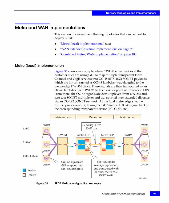
Network Topologies and Implementations
Metro and WAN implementationsThis section discusses the following topologies that can be used to deploy SRDF:
◆ “Metro (local) implementation,” next
◆ “WAN extended distance implement ion” on page 98
◆ “Combined Metro/WAN implementation” on page 100
Metro (local) implementationFigure 36 shows an example where CWDM edge devices at the customer sites are using GFP to map multiple transparent Fibre Channel and GigE services into OC-48 (STS-48C) SONET payloads which are in turn carried as OC-48 lambdas (wavelengths) to the metro edge DWDM office. These signals are then transported as an OC-48 lambdas over DWDM to telco carrier point of presence (POP). From there, the OC-48 signals are demultiplexed from DWDM and sent to a SONET multiplexer and transported over extended distance via an OC-192 SONET network. At the final metro edge site, the reverse process occurs, taking the GFP mapped OC-48 signal back to the corresponding transparent service (FC, GigE, etc.).
Figure 36 SRDF Metro configuration example
GEN-000212
Metro POPDWDM DWDMMetro POP
2 x FC
2 x GigE
1 x FC, 1 x GigE
DWDM
SONET
CWDM
CWDM
CWDM
CWDM
CWDM
CWDM
Assume signals areGFP wrapped intoSTS-48C at ingress
Use existing OC-192SONET core
STS-48C can bemanaged, groomed,and transported withall other metro core
SONET traffic
Metro access Metro core Metro access
Metro and WAN implementations 97
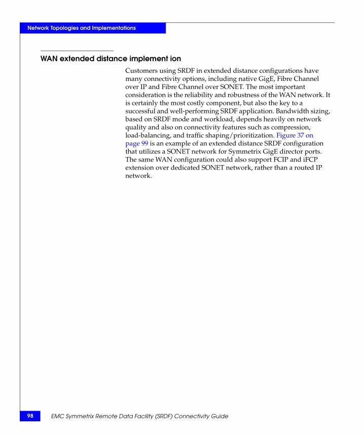
98
Network Topologies and Implementations
WAN extended distance implement ionCustomers using SRDF in extended distance configurations have many connectivity options, including native GigE, Fibre Channel over IP and Fibre Channel over SONET. The most important consideration is the reliability and robustness of the WAN network. It is certainly the most costly component, but also the key to a successful and well-performing SRDF application. Bandwidth sizing, based on SRDF mode and workload, depends heavily on network quality and also on connectivity features such as compression, load-balancing, and traffic shaping/prioritization. Figure 37 on page 99 is an example of an extended distance SRDF configuration that utilizes a SONET network for Symmetrix GigE director ports. The same WAN configuration could also support FCIP and iFCP extension over dedicated SONET network, rather than a routed IP network.
EMC Symmetrix Remote Data Facility (SRDF) Connectivity Guide
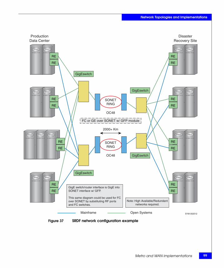
Network Topologies and Implementations
Figure 37 SRDF network configuration example
2000+ Km
OC48
FC or GE over SONET w/ GFP module
GigEswitch
Mainframe
GigEswitch
GigEswitch
GigEswitch
ProductionData Center
DisasterRecovery Site
OC48
Open Systems SYM-002512
SONETRING
SONETRING
RE
RE
RE
RE
RE
RE
RE
RE
RE
RE
RE
RE
RE
RE
RE
RE
GigE switch/router interface is GigE intoSONET interface w/ GFP.
This same diagram could be used for FCover SONET by substituting RF ports and FC switches.
Note: High Available/Redundantnetworks required.
Metro and WAN implementations 99
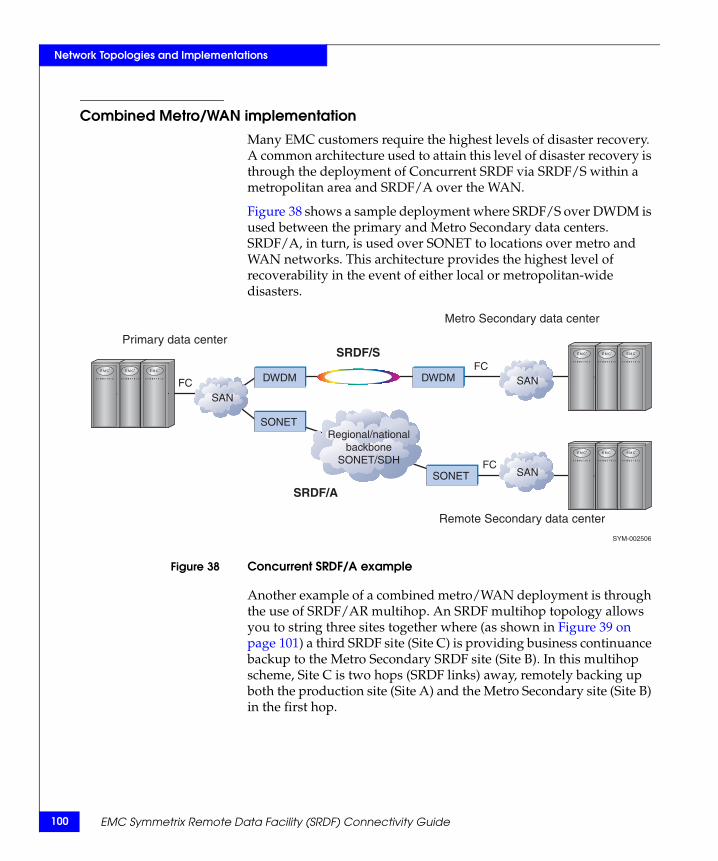
100
Network Topologies and Implementations
Combined Metro/WAN implementationMany EMC customers require the highest levels of disaster recovery. A common architecture used to attain this level of disaster recovery is through the deployment of Concurrent SRDF via SRDF/S within a metropolitan area and SRDF/A over the WAN.
Figure 38 shows a sample deployment where SRDF/S over DWDM is used between the primary and Metro Secondary data centers. SRDF/A, in turn, is used over SONET to locations over metro and WAN networks. This architecture provides the highest level of recoverability in the event of either local or metropolitan-wide disasters.
Figure 38 Concurrent SRDF/A example
Another example of a combined metro/WAN deployment is through the use of SRDF/AR multihop. An SRDF multihop topology allows you to string three sites together where (as shown in Figure 39 on page 101) a third SRDF site (Site C) is providing business continuance backup to the Metro Secondary SRDF site (Site B). In this multihop scheme, Site C is two hops (SRDF links) away, remotely backing up both the production site (Site A) and the Metro Secondary site (Site B) in the first hop.
SONET
SONET
DWDM DWDMFC
SAN
SAN
SAN
FC
FC
Regional/nationalbackbone
SONET/SDH
Metro Secondary data center
Remote Secondary data center
Primary data centerSRDF/S
SRDF/A
SYM-002506
EMC Symmetrix Remote Data Facility (SRDF) Connectivity Guide
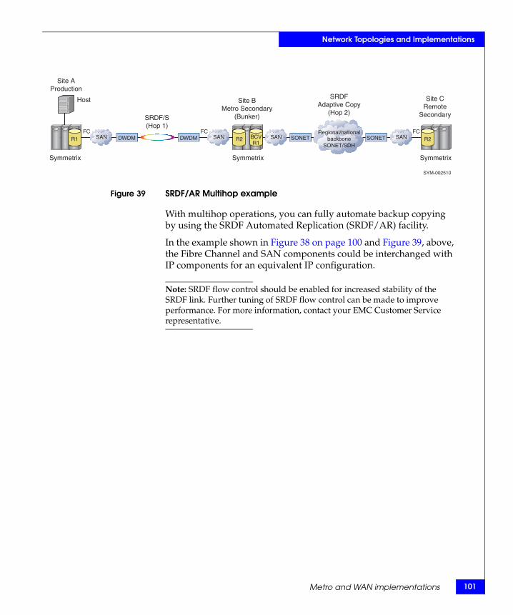
Network Topologies and Implementations
Figure 39 SRDF/AR Multihop example
With multihop operations, you can fully automate backup copying by using the SRDF Automated Replication (SRDF/AR) facility.
In the example shown in Figure 38 on page 100 and Figure 39, above, the Fibre Channel and SAN components could be interchanged with IP components for an equivalent IP configuration.
Note: SRDF flow control should be enabled for increased stability of the SRDF link. Further tuning of SRDF flow control can be made to improve performance. For more information, contact your EMC Customer Service representative.
DWDM DWDMFC
Host
SANSANFC
SRDF/S(Hop 1)
Site AProduction
Site BMetro Secondary
(Bunker)
Symmetrix
R1 SONET SONET SANSANFCRegional/national
backboneSONET/SDH
Site CRemote
Secondary
SRDFAdaptive Copy
(Hop 2)
SYM-002510
Symmetrix Symmetrix
R2 R2BCVR1
Metro and WAN implementations 101
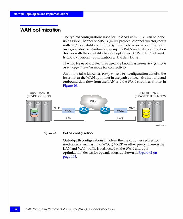
102
Network Topologies and Implementations
WAN optimizationThe typical configurations used for IP WAN with SRDF can be done using Fibre Channel or MPCD (multi-protocol channel director) ports with Gb/E capability out of the Symmetrix to a corresponding port on a given device. Vendors today supply WAN and data optimization devices with the capability to intercept either FCIP- or Gb/E- based traffic and perform optimization on the data flows.
The two types of architectures used are known as in-line /bridge mode or out-of-path /routed mode for connectivity.
An in-line (also known as bump in the wire) configuration denotes the insertion of the WAN optimizer in the path between the inbound and outbound data flow from the LAN and the WAN circuit, as shown in Figure 40.
Figure 40 In-line configuration
Out-of-path configurations involves the use of router redirection mechanisms such as PBR, WCCP, VRRP, or other proxy wherein the LAN and WAN traffic is redirected to the WAN and data optimization device for optimization, as shown in Figure 41 on page 103.
WAN
WOC WOCGb/E
LOCAL SAN / R1(DEVICE GROUPS)
REMOTE SAN / R2(DISASTER RECOVERY)
SYM-002513
LAN
Gb/E
LAN
EMC Symmetrix Remote Data Facility (SRDF) Connectivity Guide
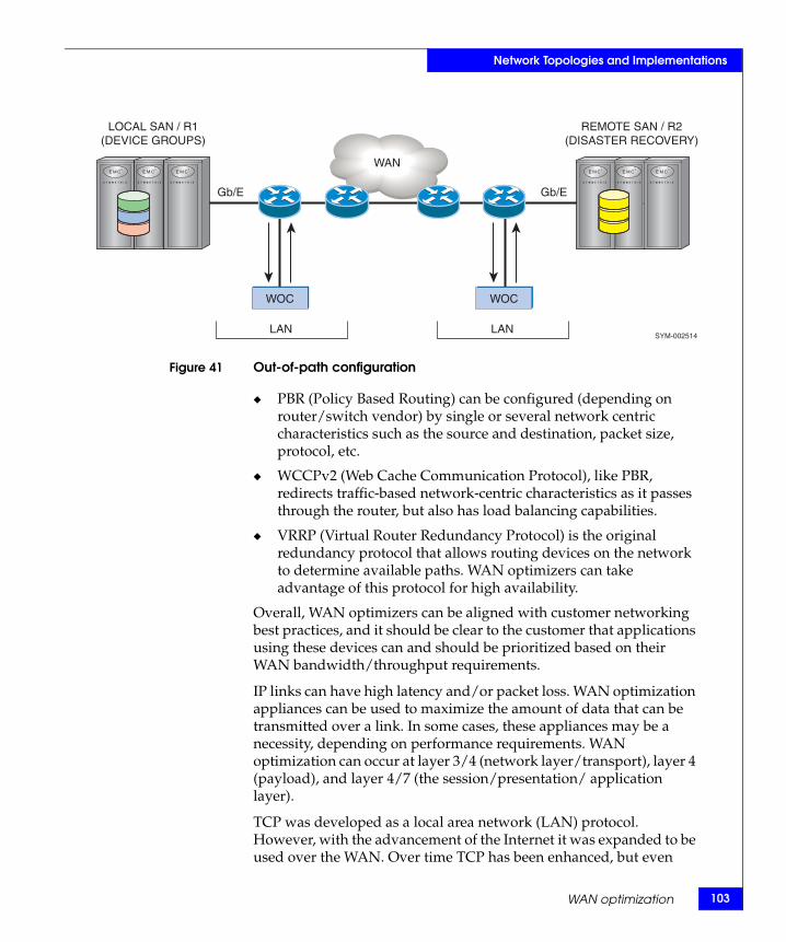
Network Topologies and Implementations
Figure 41 Out-of-path configuration
◆ PBR (Policy Based Routing) can be configured (depending on router/switch vendor) by single or several network centric characteristics such as the source and destination, packet size, protocol, etc.
◆ WCCPv2 (Web Cache Communication Protocol), like PBR, redirects traffic-based network-centric characteristics as it passes through the router, but also has load balancing capabilities.
◆ VRRP (Virtual Router Redundancy Protocol) is the original redundancy protocol that allows routing devices on the network to determine available paths. WAN optimizers can take advantage of this protocol for high availability.
Overall, WAN optimizers can be aligned with customer networking best practices, and it should be clear to the customer that applications using these devices can and should be prioritized based on their WAN bandwidth/throughput requirements.
IP links can have high latency and/or packet loss. WAN optimization appliances can be used to maximize the amount of data that can be transmitted over a link. In some cases, these appliances may be a necessity, depending on performance requirements. WAN optimization can occur at layer 3/4 (network layer/transport), layer 4 (payload), and layer 4/7 (the session/presentation/ application layer).
TCP was developed as a local area network (LAN) protocol. However, with the advancement of the Internet it was expanded to be used over the WAN. Over time TCP has been enhanced, but even
WAN
WOC WOC
Gb/E
LOCAL SAN / R1(DEVICE GROUPS)
REMOTE SAN / R2(DISASTER RECOVERY)
SYM-002514LAN
Gb/E
LAN
WAN optimization 103
104
Network Topologies and Implementations
with these enhancements TCP is still not well suited for WAN use for many applications.
The primary factors that directly impact TCP's ability to be optimized over the WAN are latency, packet loss, and the amount of bandwidth to be used. It is these factors on which the layer 3/4 optimization products focus. Many of these optimization products will re-encapsulate the packets into UDP or some other protocol. Some products create tunnels of one sort or another to perform their peer-to-peer connection between appliances for the optimized data.
Layer 3 optimization refers to the payload (data) within the packet and focuses on the reduction of actual payload as it passes over the network through the use of data compression, or data deduplication engines (DDEs). Compression is performed through the use of data compression algorithms (refer to “Compression” on page 54). A second type of data reduction is data deduplication using large data pattern tables and associated pointers (fingerprints). Large amounts of memory and/or hard-drive storage are used to store these pattern tables and pointers. These appliances build tables with pointers associated to the data that is to be reduced. Identical tables are built in the optimization appliances on both sides of the WAN with only smaller pointers passed over the network (versus resending data). While typical LZ compression ratio is about 2:1, DDE ratios can range greatly, depending on many factors. In general, 5:1 (and sometimes much higher ratios) can be achieved.
Layer 4/7 optimization is what is called the "application" layer of optimization. This area of optimization can take many approaches that can vary widely, but are generally done through the use of application-aware optimization engines. The actions taken by these engines can result in benefits, including reductions in the number of transactions that occur over the network or more efficient use of bandwidth. It is also at this layer the TCP optimization occurs.
Note: WAN optimization appliances deployed within IP networks are qualified by EMC. Consult the EMC Support Matrix for WAN optimization appliances that can be used with SRDF.
EMC Symmetrix Remote Data Facility (SRDF) Connectivity Guide
Network Topologies and Implementations
IMPORTANT!Compression should be disabled on the GigE ports on the MPCD and the GigE director when a WAN optimization device employing data optimization is used. If compression is enabled on the GigE ports on the MPCD and the GigE director, data optimization benefits will be severely impacted resulting in increased WAN bandwidth needs.
WAN optimization 105
106
Network Topologies and Implementations
Best practices, recommendations, and considerationsThis section provides best practices, recommendations, and considerations for:
◆ “SRDF over a Metro or WAN”, next
◆ “SRDF/AR and adaptive copy” on page 109
◆ “SRDF/A” on page 110
◆ “SRDF/Star” on page 112
◆ “GigE” on page 113
◆ “Fibre Channel” on page 116
◆ “ESCON/FarPoint” on page 117
SRDF over a Metro or WAN
This section provides some best practices, recommendations, and configurations for involving SRDF over a Metro or WAN:
◆ SRDF zoning:
• If the administrator so chooses, SRDF Single Zoning, where multiple sources and targets are contained in a single zone, can be used.
• An SRDF zone should strictly contain RF ports.
• If multiple zones are used, zoning must be designed in such a way that functionality, such as Dynamic SRDF, meets customer requirements. For example, if Dynamic SRDF is or will be in use, zoning requirements may change. In the case of Dynamic SRDF, any RFs that may have Dynamic SRDF connectivity established to one another must be in the same zone.
◆ A maximum of 10 RFs per switch is recommended. For example, say you have a two site configuration with four DMXs in each site. Each DMX contributes four SRDF ports. No single switch should have more than ten RFs connected to it. In this example, a minimum of two switches would need to be deployed at each site. The main reason for restricting a switch to ten RFs is due to NameServer traffic. NameServer traffic is an important consideration and needs to be kept to a minimum in order to
EMC Symmetrix Remote Data Facility (SRDF) Connectivity Guide
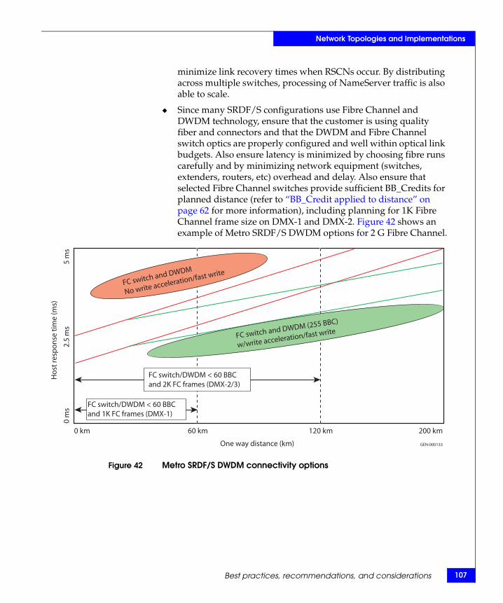
Network Topologies and Implementations
minimize link recovery times when RSCNs occur. By distributing across multiple switches, processing of NameServer traffic is also able to scale.
◆ Since many SRDF/S configurations use Fibre Channel and DWDM technology, ensure that the customer is using quality fiber and connectors and that the DWDM and Fibre Channel switch optics are properly configured and well within optical link budgets. Also ensure latency is minimized by choosing fibre runs carefully and by minimizing network equipment (switches, extenders, routers, etc) overhead and delay. Also ensure that selected Fibre Channel switches provide sufficient BB_Credits for planned distance (refer to “BB_Credit applied to distance” on page 62 for more information), including planning for 1K Fibre Channel frame size on DMX-1 and DMX-2. Figure 42 shows an example of Metro SRDF/S DWDM options for 2 G Fibre Channel.
Figure 42 Metro SRDF/S DWDM connectivity options
Hos
t res
pons
e tim
e (m
s)
0 m
s2.
5 m
s5
ms
FC switch/DWDM < 60 BBCand 2K FC frames (DMX-2/3)
FC switch/DWDM < 60 BBCand 1K FC frames (DMX-1)
0 km 60 km 120 km 200 km
One way distance (km) GEN-000133
FC switch and DWDM
No write acceleration/fast write
FC switch and DWDM (255 BBC)
w/write acceleration/fast write
Best practices, recommendations, and considerations 107
108
Network Topologies and Implementations
◆ For point-to-point, low throughput SRDF deployments, best practice is to deploy a minimum of two links. For higher throughput SRDF/S deployments, best practice is to deploy at least four Fibre Channel (RF) links per Symmetrix since DMX scales well beyond 8 links. Ensure enough links to keep link utilization around 50% to minimize host response time for SRDF/S.
◆ For Metro SRDF/S implementations using DWDM or extended distance WAN connectivity, it is not recommended to extend Fibre Channel fabrics containing local host/storage traffic between data centers along with SRDF/S. Best practice is to isolate local host/storage fabrics within data centers so that link outages cannot cause disruption to the host connections to the SAN. Extension of ISL links between data centers over DWDM or WAN links can cause host timeouts (up to 25 seconds) if the SANs are not isolated, and the fabric goes through a rebuild process due to ISL failures. Recommendation is to use Fibre Channel features, such VSANs or FC routing, to prevent merging of the local and remote fabrics.
◆ Each Fibre Channel (RF) or GigE link should have a minimum of 10 Mb/s of dedicated bandwidth. On GigE interfaces, always set the speed limit in the Symmetrix Configuration file for each port, if bandwidth is less than 1 Gb/s per GigE port. Speed Limit should be set to (90% * available bandwidth / # GigE ports). When using Fibre Channel over extended distances, consider using SiRT on the SRDF/S links, or fast write/write acceleration in FC switches to eliminate one of two round trips per FC write I/O. Ensure that the group Speed Limit (if available) is enabled across all REs.
◆ As best practice, do not share RA ports between SRDF/S and SRDF/A groups. When doing data migrations (adaptive copy), use separate RAs, when possible, to minimize performance impacts.
◆ Packet loss should be zero, but should never exceed 0.1%. Latency over distance is a given. Packet loss is not. Design the network to be resilient by having diverse network paths with the ability to self-heal and transparently failover. Ensure the network is able to scale to allow for future growth.
EMC Symmetrix Remote Data Facility (SRDF) Connectivity Guide
Network Topologies and Implementations
SRDF/AR and adaptive copy This section provides recommendations and considerations for SRDF/AR and adaptive copy:
◆ SRDF operations for SRDF/AR and adaptive copy Disk mode transmit full tracks across the links as SRDF copy tasks. DMX-1 and DMX-2 use 32K (OS) and 56K (MF) tracks, while DMX-3, DMX-4, and VMAX use 64K and 56K tracks, respectively. The exception for DMX-3, DMX-4, and VMAX is when the R2-side Symmetrix is an older model. In this case, the R1-side DMX-3, DMX-4, and VMAX will send 64K OS tracks as two 32K tracks to the older Symmetrix. This does not affect mainframe I/O because of the standard 56K track size.
◆ The SRDF copy tasks (invalid tracks owed to the secondary Symmetrix) are controlled by the DAs. The DAs are responsible for fetching the invalid tracks and placing them on the SRDF copy queues. The priority of the background copy tasks versus the higher priority destaging of writes in cache to physical disk is controlled by the SRDF QoS setting and the DA copy task (also referred to as copy job) parameter.
◆ This DA copy track parameter is the number of tracks that the DAs will place on the SRDF copy queue at a time. In Enginuity version 5x71, the default value was doubled from 40 (28 hex) tracks to 80 (50 hex) tracks per SRDF group. For VMAX, this setting is 256 (100 hex) tracks per SRDF group. Since this is the maximum number of tracks that can be on the SRDF queue per SRDF group, performance will be throttled over high latency links. For long-distance replication, the parameter may be increased by EMC Customer Service to improve performance (max value is 255). For example, two SRDF links at 40 ms RTT: Assuming Enginuity version 5x71, 80 tracks X 32K/track / 40 ms = 64 MB/s peak (2 RE (GigE) or 2 RF w/ fast write support). This throughput would drop about 20-30% (~50 MB/s) if two round trips over Fibre Channel are used.
◆ Spreading the volumes across multiple SRDF groups for long-haul data migrations will also provide a multiplier for performance, but be aware that adjusting the DA copy task setting may impact DA destaging of host writes from cache and host response time. For Enginuity version 5670 on DMX-1 and DMX-2, if production is active during data migrations, do not increase copy task setting beyond 70 (46 hex) and use SRDF QoS
Best practices, recommendations, and considerations 109
110
Network Topologies and Implementations
to limit front-end impact during the replication process. Keep in mind that adaptive copy mode will run much more efficiently if many volumes are active (use host striping and metal, etc.) and spread across the physical disks.
SRDF/A This section contains some considerations and best practices for SRDF/A.
Some considerations for SRDF/A include:
SRDF/A, unlike adaptive copy, is not throttled by DA activity since the SRDF updates are retained directly in cache for transfer to the secondary Symmetrix. SRDF/A will burst at the SRDF link limits, whether its measured in maximum I/Os per second per link for smaller writes, or MB/s for large writes, since the I/Os are only throttled by the following two parameters:
◆ Number of I/Os allowed on the SRDF link per volume: 8 for ESCON; 32 for Fibre Channel or GigE
◆ Number of SRDF I/Os allowed on the SRDF link: 400
Typically, the two round trips (FC) versus one (GigE or Write Acceleration) does not impact SRDF/A performance since SRDF/A will send continuous stream of writes until the cycle is empty. If the links are kept full, there is no waiting for round trip delay and SRDF/A performance is not impacted by two round trips. Fibre Channel fast writes will improve performance for SRDF/A when there are "gaps" on the links due to retransmissions after link errors, or small writes that throttle SRDF throughput due to hitting I/Os per second limits on the Fibre Channel or GigE links. The number of active volumes in a cycle can also affect performance on links where the links may be hitting the 32 writes/volume limit. Both Fibre Channel and GigE links load balance on disparate links (different speeds/latencies).
Some best practices for SRDF/A include:
◆ Do not over-subscribe the link! SRDF/A does not put data on the link in a steady stream. It does it in bursts at the SRDF link limit. If you have several SRDF groups, and if these SRDF groups have different peak I/O periods, one might think that it would be possible to set the throttle rate for an individual SRDF group to a level that is less than the overall bandwidth. However, the overall combined throttle rate must be calculated with regard to all SRDF
EMC Symmetrix Remote Data Facility (SRDF) Connectivity Guide
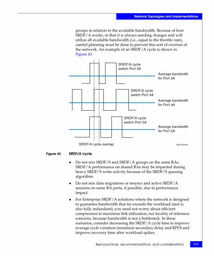
Network Topologies and Implementations
groups in relation to the available bandwidth. Because of how SRDF/A works, in that it is always sending changes and will utilize all available bandwidth (i.e., equal to the throttle rate), careful planning must be done to prevent this sort of overrun of the network. An example of an SRDF/A cycle is shown in Figure 43.
Figure 43 SRDF/A cycle
◆ Do not mix SRDF/S and SRDF/A groups on the same RAs. SRDF/A performance on shared RAs may be impacted during heavy SRDF/S write activity because of the SRDF/S queuing algorithm.
◆ Do not mix data migrations or resyncs and active SRDF/A sessions on same RA ports, if possible, due to performance impact.
◆ For Enterprise SRDF/A solutions where the network is designed to guarantee bandwidth that far exceeds the workload (and is also fully redundant), you need not worry about efficient compression to maximize link utilization, nor locality of reference concerns, because bandwidth is not a bottleneck. In these scenarios, consider decreasing the SRDF/A cycle time to improve average cycle variation (minimize secondary delay and RPO) and improve recovery time after workload spikes.
GEN-000218
SRDF/A cycleswitch Port 3A
SRDF/A cycleswitch Port 4A
SRDF/A cycleswitch Port 5A
Average bandwidthfor Port 3A
Average bandwidthfor Port 4A
Average bandwidthfor Port 5A
SRDF/A cycle overlap
Best practices, recommendations, and considerations 111
112
Network Topologies and Implementations
The problem with high bandwidth and 30-second cycles is that the SRDF transfers complete in a fraction of the 30-second cycle, then must wait for the 30-second timer to expire rather than trying to switch cycles as soon as the data transfer completes to the R2s. A shorter cycle will also flatten out the peaks more efficiently by decreasing the amount of cycle elongation during workload spikes.
In single session SRDF/A, you can reduce the cycle time. Refer to the appropriate MSC documentation for more information.
SRDF/StarThe following is a best practice and recommendation for SRDF/Star:
The three-site WAN network for Star must be designed so that all WAN links are active during Concurrent SRDF operation between production data center and the bunker and DR sites (A to B and A through B to C, as shown in Figure 44 on page 113. This provides better performance and ensures that the WAN links are functional when a failover to site B or C occurs, rather than having a "standby" link between Bunker (site B) and DR site (C) that is only used when a disaster is declared.
The example configuration shown in Figure 44 uses Fibre Channel switches to provide exchange-based routing across all ISLs and FSPF to round robin between all available WAN paths. Because the Fibre Channel switches have ISLs that can access all WAN links (directly from production to DR (A-C) and via DWDM to Bunker site, then onto second WAN link to DR site (A-B-C)), equal cost FSPF for the two WAN links guarantees that both WANs will be active from production site for asynchronous replication (SRDF/A) to DR site.
EMC Symmetrix Remote Data Facility (SRDF) Connectivity Guide
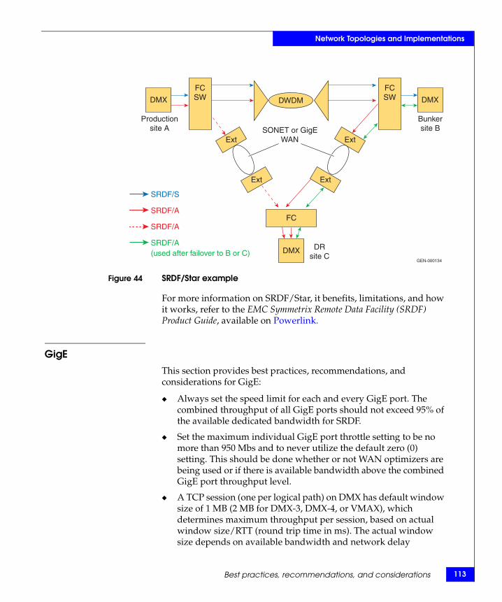
Network Topologies and Implementations
Figure 44 SRDF/Star example
For more information on SRDF/Star, it benefits, limitations, and how it works, refer to the EMC Symmetrix Remote Data Facility (SRDF) Product Guide, available on Powerlink.
GigEThis section provides best practices, recommendations, and considerations for GigE:
◆ Always set the speed limit for each and every GigE port. The combined throughput of all GigE ports should not exceed 95% of the available dedicated bandwidth for SRDF.
◆ Set the maximum individual GigE port throttle setting to be no more than 950 Mbs and to never utilize the default zero (0) setting. This should be done whether or not WAN optimizers are being used or if there is available bandwidth above the combined GigE port throughput level.
◆ A TCP session (one per logical path) on DMX has default window size of 1 MB (2 MB for DMX-3, DMX-4, or VMAX), which determines maximum throughput per session, based on actual window size/RTT (round trip time in ms). The actual window size depends on available bandwidth and network delay
DMX
DMX
DMX
FCSW
FCSW
Ext
Ext
FC
SONET or GigEWAN Ext
Ext
SRDF/S
SRDF/A
SRDF/A
SRDF/A(used after failover to B or C)
Productionsite A
Bunkersite B
DRsite C
GEN-000134
DWDM
Best practices, recommendations, and considerations 113
114
Network Topologies and Implementations
(Bandwidth * RTT). In a switched configuration, where all primary GigE ports "see" all secondary GigE ports, then the number of TCP sessions is the number of primary ports multiplied by the number of secondary ports. GigE, like switched FC, supports point-to-multipoint configurations.
◆ To prevent link problems, it is recommended to use minimum of 10 Mb/s per GigE port (RPQ for > 6 Mb/s). If the link is not on a quality (.01% or less packet loss) network, RTT should be limited to under 60 ms to prevent link recovery and performance problems. For networks that have packet loss problems that are over 40 ms RTT, WAN optimization products should be considered to help improve performance through optimized retransmissions and recovery. For Enginuity version 5873 and later, it is a best practice is to utilize the auto-adjust speed limit feature across a group of GigE ports. Any number of SRDF over GigE ports can be grouped together using an aggregate bandwidth for the entire group. The speed limit feature will automatically adjust the speed limits for the individual ports to maintain that bandwidth into the network should any of the group's ports become inactive (for any reason).
Note: Ensure that the customers' IP networks are using end-to-end routing (not packet level) to prevent out-of-order packets. GigE will re-order packets, but it will affect performance.
◆ Consider the use of a WAN optimization appliance if any one or a combination of bandwidth, latency, and/or packet loss are limiting factors. When using these appliances, please note the following:
• If the WAN optimizer does not support auto disabling of compression for the GigE ports, compression should be disabled (in the Symmetrix configuration) for each GigE port on the MPCD and the GigE director port, when a WAN optimization device employing data optimization is used. If compression is enabled on the GigE ports on the MPCD and the GigE director, data optimization benefits will be severely impacted resulting in increased WAN bandwidth needs.
• When using GigE, SRDF flow control is on by default for increased stability of the SRDF link. Further tuning of SRDF flow control can be made to improve performance. For more
EMC Symmetrix Remote Data Facility (SRDF) Connectivity Guide
Network Topologies and Implementations
information, please contact your EMC Customer Service representative.For more information on flow control, refer to “Flow control” on page 50.
• Refer to the EMC Networked Storage Topology Guide regarding configuration details and settings for specific WAN optimization appliances when used with SRDF. SRDF link stability and/or performance can be severely compromised if the correct settings on the WAN optimization appliances are not made.
• In general, with WAN optimizers, it has been observed that optimization ratios and or throughput levels may be higher when using GigE ports out of the Symmetrix as opposed to what may be achieved when using an FCIP extender. There are many factors that impact how much optimization will occur, therefore results will vary.
• In general, it has been observed that optimization ratios are higher with SRDF/A than SRDF Adaptive Copy. There are many factors that impact how much optimization will occur, therefore results will vary.
◆ DMX to Symmetrix 8000 GigE configurations must be carefully planned. In these configurations, compression is auto-disabled so bandwidth is not efficiently used. GigE flow control is not available with Symmetrix 8000, so low-bandwidth, high-latency links will not be able to effectively utilize the bandwidth. Consider using external compression products. Additional bandwidth provisioning may also be required.
◆ Spanning Tree Protocol (STP) is commonly used in many large networks where three or more switches are attached together within the network. One downside of STP is that when a change occurs within the switched fabric, an updating of the mapping tables has to take place. During this update process, all traffic is stopped within the VLANs that were affected by the change until the update has finished. This update typically takes anywhere from 30 to 60 seconds. SRDF links can drop due to the length of the outage unless Link Limbo timer and Transmit Idles features are invoked for the SRDF links.
On Cisco switches that transport SRDF traffic and where the VLAN that they utilize could be affected by a STP reconvergence, it is recommended that a feature called portfast, fastlink, or fastbackbone be enabled. This feature allows for an instant failover without having to wait for the reconvergence time. For non-Cisco
Best practices, recommendations, and considerations 115
116
Network Topologies and Implementations
switch equipment, it should be determined if such a feature is supported and if it possible for this feature to be enabled. If this feature is not enabled, it is recommended that if a known forced reconvergence is to occur (for example, maintenance within a network) that appropriate measures be taken to lessen the effect of the timeout on SRDF traffic. For instance, if a maintenance event is scheduled and SRDF/A is active, it would be recommended to change to SRDF adaptive copy mode during this period.
Fibre ChannelThis section provides best practices, recommendations, and considerations for Fibre Channel.
◆ Consider the use of a WAN optimization appliance if any one or a combination of bandwidth, latency, and/or packet loss are limiting factors. When using these appliances, please note the following:
• Compression should be disabled (in the Symmetrix configuration) on any device (such as FCIP channel extenders) prior to ingress of a WAN optimization device employing data deduplication. If compression is enabled, data deduplication benefits will be severely impacted resulting in increased WAN bandwidth needs.
• SRDF flow control should be enabled for increased stability of the SRDF links. Further tuning of SRDF flow control can be made to improve performance. For more information, please contact your EMC Customer Service representative. Refer to Table 1 on page 28 for information on flow control support. For more information on flow control, refer to “Flow control” on page 50.
• Refer to the EMC Networked Storage Topology Guide regarding configuration details and settings for specific WAN optimization appliances and FCIP devices when used with SRDF. SRDF link stability and/or performance can be severely compromised if the correct settings on the WAN optimization appliances and FCIP devices are not made.
• In general, it has been observed that optimization ratios are higher with GigE ports on the MPCD and the GigE director vs. FCIP. There are many factors that impact how much optimization will occur, therefore results will vary.
EMC Symmetrix Remote Data Facility (SRDF) Connectivity Guide
Network Topologies and Implementations
• In general, it has been observed that optimization ratios are higher with SRDF/A than SRDF Adaptive Copy. There are many factors that impact how much optimization will occur, therefore results will vary.
ESCON/FarPoint
This section provides best practices, recommendations, and considerations for ESCON/FarPoint:
◆ ESCON FarPoint requires at least 1.5 Mb/s of bandwidth per RA and supports T1/E1, T3/E3 point-to-point WAN circuits, as well as ATM/OC3, SONET, and IP networks, using extenders. Throughput per RA link is limited to 10-12 MB/s, but for low- bandwidth (T3), low-throughput SRDF applications, FarPoint is still a viable configuration. As the legacy SRDF protocol, it is limited by scalability (8 ESCON links < performance of single Fibre Channel link) and uni-directional limitations.
◆ FarPoint protocol eliminates standard ESCON flow control/ hand-shaking to maximize performance over distance. There are only two parameters (settable in Symmetrix Configuration file or by EMC Customer Service) to manage the performance and streaming of data on a FarPoint RA link.
• The first parameter is used for troubleshooting, controls the number of idles between 1 K ESCON frames, and therefore directly affects the peak throughput (10-12 MB/s) of the links.
• The second, and more important, parameter is often used by EMC Customer Service personnel to "tune" the FarPoint links is the FarPoint Buffer setting. This parameter (Symmetrix Configuration file default is 200,000 bytes per RA) is the maximum amount of data that an RA can pipeline on the link (truncated to multiples of full write I/Os, since partial writes cannot be transmitted on an SRDF link). This value divided by round trip time (RTT) determines maximum throughput (MB/s) per RA.
The value is frequently decreased for low bandwidth links (speed matching) to prevent over-running network extender buffering. For long distance data migrations, the FarPoint Buffer size can be increased by EMC Customer Service to improve FarPoint performance. The RA pipeline depth (average I/O on the link) and round trip times are displayed in the 'A2, F3' RA statistics as queue depth and Echo time.
Best practices, recommendations, and considerations 117

118
Network Topologies and Implementations
EMC Symmetrix Remote Data Facility (SRDF) Connectivity Guide
AInvisible Body Tag
This appendix contains information on network cable specifications and supported distances.
◆ Cable specifications and supported distances ............................. 120
Cable Specifications
Cable Specifications 119
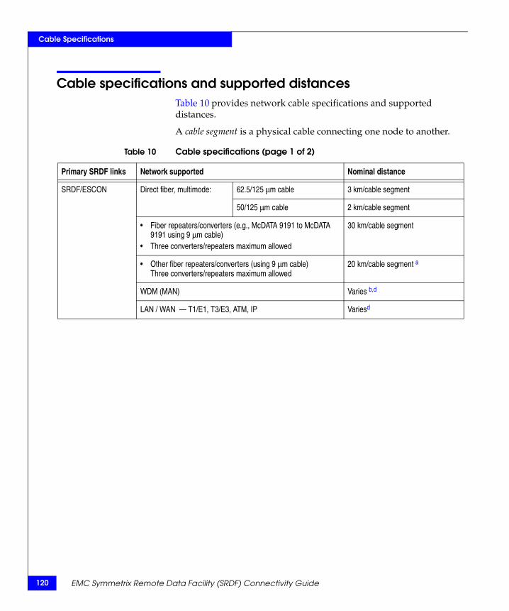
120
Cable Specifications
Cable specifications and supported distancesTable 10 provides network cable specifications and supported distances.
A cable segment is a physical cable connecting one node to another.
Table 10 Cable specifications (page 1 of 2)
Primary SRDF links Network supported Nominal distance
SRDF/ESCON Direct fiber, multimode: 62.5/125 μm cable 3 km/cable segment
50/125 μm cable 2 km/cable segment
• Fiber repeaters/converters (e.g., McDATA 9191 to McDATA 9191 using 9 μm cable)
• Three converters/repeaters maximum allowed
30 km/cable segment
• Other fiber repeaters/converters (using 9 μm cable)Three converters/repeaters maximum allowed
20 km/cable segment a
WDM (MAN) Varies b,d
LAN / WAN — T1/E1, T3/E3, ATM, IP Variesd
EMC Symmetrix Remote Data Facility (SRDF) Connectivity Guide
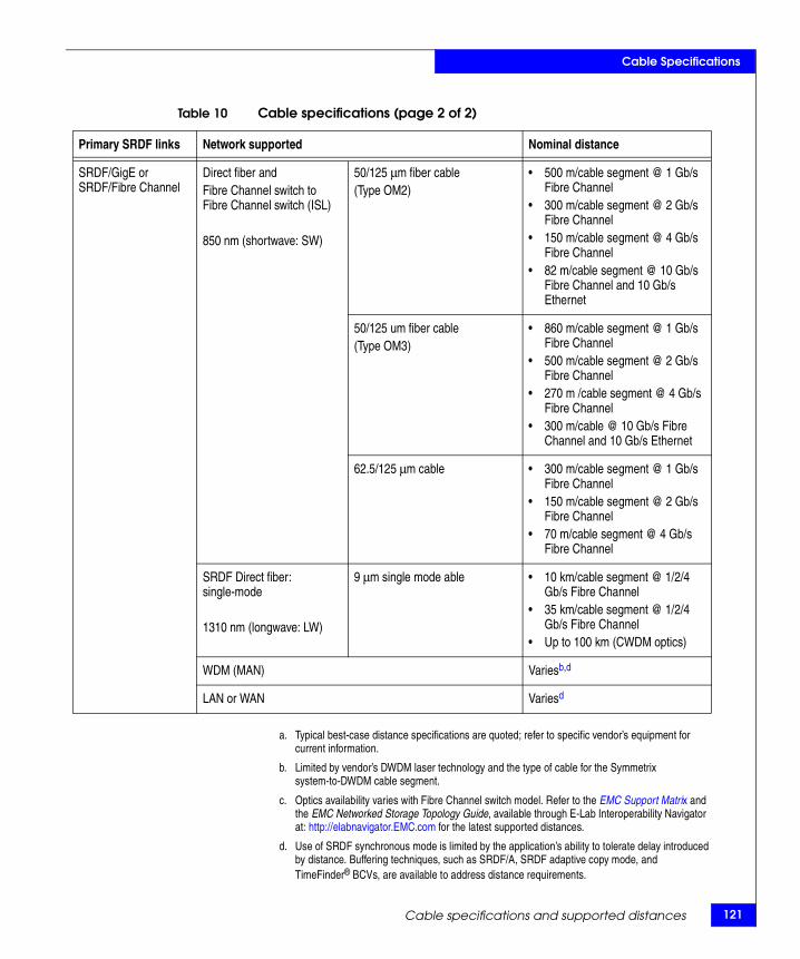
Cable Specifications
a. Typical best-case distance specifications are quoted; refer to specific vendor’s equipment for current information.
b. Limited by vendor’s DWDM laser technology and the type of cable for the Symmetrix system-to-DWDM cable segment.
c. Optics availability varies with Fibre Channel switch model. Refer to the EMC Support Matrix and the EMC Networked Storage Topology Guide, available through E-Lab Interoperability Navigator at: http://elabnavigator.EMC.com for the latest supported distances.
d. Use of SRDF synchronous mode is limited by the application’s ability to tolerate delay introduced by distance. Buffering techniques, such as SRDF/A, SRDF adaptive copy mode, and TimeFinder® BCVs, are available to address distance requirements.
SRDF/GigE orSRDF/Fibre Channel
Direct fiber and Fibre Channel switch to Fibre Channel switch (ISL)
850 nm (shortwave: SW)
50/125 μm fiber cable (Type OM2)
• 500 m/cable segment @ 1 Gb/s Fibre Channel
• 300 m/cable segment @ 2 Gb/s Fibre Channel
• 150 m/cable segment @ 4 Gb/s Fibre Channel
• 82 m/cable segment @ 10 Gb/s Fibre Channel and 10 Gb/s Ethernet
50/125 um fiber cable (Type OM3)
• 860 m/cable segment @ 1 Gb/s Fibre Channel
• 500 m/cable segment @ 2 Gb/s Fibre Channel
• 270 m /cable segment @ 4 Gb/s Fibre Channel
• 300 m/cable @ 10 Gb/s Fibre Channel and 10 Gb/s Ethernet
62.5/125 μm cable • 300 m/cable segment @ 1 Gb/s Fibre Channel
• 150 m/cable segment @ 2 Gb/s Fibre Channel
• 70 m/cable segment @ 4 Gb/s Fibre Channel
SRDF Direct fiber: single-mode
1310 nm (longwave: LW)
9 μm single mode able • 10 km/cable segment @ 1/2/4 Gb/s Fibre Channel
• 35 km/cable segment @ 1/2/4 Gb/s Fibre Channel
• Up to 100 km (CWDM optics)
WDM (MAN) Variesb,d
LAN or WAN Variesd
Table 10 Cable specifications (page 2 of 2)
Primary SRDF links Network supported Nominal distance
Cable specifications and supported distances 121
122
Cable Specifications
CAUTION!Some vendors place very powerful lasers in their systems to improve signal strength. Other vendors have receivers that can be damaged or even destroyed by this intense light. Based on the connection distance involved, light attenuation may be needed between equipment. Check input and output ranges carefully before operational testing.
EMC Symmetrix Remote Data Facility (SRDF) Connectivity Guide

BInvisible Body Tag
This appendix provides bandwidth ratings for the various WAN links.
◆ Bandwidth by WAN link ................................................................ 124
Bandwidth by WAN Link
Bandwidth by WAN Link 123
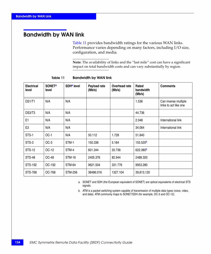
124
Bandwidth by WAN Link
Bandwidth by WAN linkTable 11 provides bandwidth ratings for the various WAN links. Performance varies depending on many factors, including I/O size, configuration, and media.
Note: The availability of links and the “last mile” cost can have a significant impact on total bandwidth costs and can vary substantially by region.
a. SONET and SDH (the European equivalent of SONET) are optical equivalents of electrical STS signals.
b. ATM is a packet switching system capable of transmission of multiple data types (voice, video, and data). ATM commonly maps to SONET/SDH (for example, OC-3 and OC-12).
Table 11 Bandwidth by WAN link
Electrical level
SONETa level
SDHa level Payload rate (Mb/s)
Overhead rate (Mb/s)
Rated bandwidth (Mb/s)
Comments
DS1/T1 N/A N/A 1.536 Can inverse multiple links to act like one
DS3/T3 N/A N/A 44.736
E1 N/A N/A 2.048 International link
E3 N/A N/A 34.064 International link
STS-1 OC-1 N/A 50.112 1.728 51.840
STS-3 OC-3 STM-1 150.336 5.184 155.520b
STS-12 OC-12 STM-4 601.344 20.736 622.080b
STS-48 OC-48 STM-16 2405.376 82.944 2488.320
STS-192 OC-192 STM-64 9621.504 331.776 9953.280
STS-768 OC-768 STM-256 38486.016 1327.104 39,813,120
EMC Symmetrix Remote Data Facility (SRDF) Connectivity Guide
Glossary
This glossary contains terms related to disk storage subsystems. Many of these terms are used in this manual.
AATM Asynchronous Transfer Mode, a high-speed, connection-oriented
switching technology that can transmit voice, video, and data traffic simultaneously through fixed-length packets called cells. ATM is used as a protocol for LAN and WAN traffic, as well as a transport protocol for IP packets. ATM is generally associated with SONET, which provides the optical link layer.
adaptive copy diskmode (AD)
Symmetrix SRDF Adaptive copy disk mode is designed for bulk data transfer. Host write tasks accumulate on the primary volume rather than in global memory. A background process destages the write tasks to the corresponding secondary volume. When a skew value is reached, the primary volume reverts to its primary mode of operation, either synchronous or semi-synchronous, whichever is currently specified.
adaptive copy mode Symmetrix SRDF Adaptive copy modes facilitate data sharing and migration. These modes allow the primary and secondary volumes to be more than one I/O out of synchronization. The maximum number of I/Os that can be out of synchronization is known as the maximum skew value. The default value is equal to the entire logical volume. The maximum skew value for a volume can be set using the SRDF monitoring and control software.
EMC Symmetrix Remote Data Facility (SRDF) Connectivity Guide 125
126
adaptive copy writepending mode (AW)
An SRDF mode of operation that stores new data for a remotely mirrored pair in the cache of the local Symmetrix storage subsystem until it can be successfully written to both the primary and secondary volumes.
Asynchronous SRDF SRDF/Asynchronous (SRDF/A) mode for SRDF secondary devices provides a dependent-write consistent copy on the R2 device, which is only slightly behind the currency of the primary R1 device. SRDF/A session data is transferred to the remote Symmetrix system in cycles or delta sets, which minimizes the redundancy of same-track changes being transferred over the SRDF links.
automatedreplication
SRDF/Automated Replication (SRDF/AR) performs automated consistent replication of data from standard devices and from BCV R1 devices over SRDF links to the remote SRDF pair.
Bback-up The process of creating a copy of data to ensure against accidental
loss.
BCV device A Business Continuance Volume (BCV) is Symmetrix storage device that holds a mirror copy of the primary data on the Standard device. A BCV Device contains a copy of data from a standard Symmetrix device that is online for regular I/O operation from its host(s). The Standard device and its assigned and mirroring BCV device are known as a BCV pair.
BCV pair The Standard device and its assigned and mirroring BCV device are known as a BCV pair.
bidirectional SRDF link If an SRDF group contains both primary and secondary volumes, write operations move data in both directions over the SRDF links for that group. This is called an SRDF bidirectional configuration.
bit The smallest unit of computer memory. A bit can hold a value of zero or one.
Buffer-to-Buffer Credits(BB_Credits)
The number of internal 2 KB buffers on a communications chip in a Fibre Channel device. More credits for longer distance enables more efficient use of the available link capacity.
business continuance Solutions that maintain mirror images of data at the device level in Symmetrix systems located locally and in physically separate sites.
EMC Symmetrix Remote Data Facility (SRDF) Connectivity Guide
Both TimeFinder and SRDF operations provide a recovery solution for component site failures between locally and remotely located storage devices.
business continuancevolumes (BCVs)
A standard Symmetrix device with special attributes that allow it to independently support applications and processes, such as backup operations, restore operations, Decision Support operations, and application testing. BCV devices are available through the EMC TimeFinder software.
byte Any 8-bit unit of data storage. For SRDF applications with FC, GigE, and ESCON, a byte is 10 bits.
Ccache Random access electronic storage used to retain frequently used data
from disk for faster access by the host.
cache slot Unit of cache equivalent to one track.
Cascaded SRDF A three-site SRDF replication configuration that provides a data recovery solution. This uses a device (R21) that is both and R2 to an R1 mirror and an R1 to an R2 mirror.
change tracker A tool available to EMC field engineers to aid in the estimation of bandwidth required in an SRDF configuration. Change Tracker allows a user to monitor the update activity on Symmetrix devices, and is especially useful for sizing SRDF in a multihop configuration.
Change Tracker consists of two programs: a collector program that gathers the update activity statistics, and a reporter program that analyzes the data and formats it into useful reports.
channel director The component in the Symmetrix subsystem that interfaces between the host and data storage. It transfers data between the host and global memory.
clone TimeFinder/Clone operations allow you to create point-in-time copies of a source (prime or backup) device on multiple target devices.
compatible peer Symmetrix Enginuity version 5568 (and later) enables the Symmetrix system to support native IBM Peer-to-Peer Remote Copy (PPRC)
EMC Symmetrix Remote Data Facility (SRDF) Connectivity Guide 127
128
commands through a Symmetrix feature called EMC Compatible Peer.
concurrent SRDF Supports the ability for a single primary volume to be remotely mirrored to two secondary volumes concurrently. This feature is called Concurrent SRDF and is supported in ESCON, Fibre Channel, and Gigabit Ethernet SRDF configurations. In Concurrent SRDF, R11 volumes must be assigned to two different SRDF groups. This is because each remote mirror can only be assigned to one SRDF group, even if the two secondary volumes reside in the same Symmetrix system.
consistency group A consistency group (CG), known as SRDF/CG) is a group comprised of primary SRDF devices, which have been enabled for remote point-in-time consistency. These SRDF consistency groups operate in unison to preserve the integrity and dependent-write consistency of a database distributed across multiple Symmetrix systems.
Count-Key-Data(CKD)
A data recording format employing self-defining record formats, used in mainframe hosts, in which each record is represented by a count area that identifies the record and specifies its format, an optional key area that may be used to identify the data area contents, and a data area that contains the user data for the record. CKD can also refer to a set of channel commands that are accepted by a device that employs the CKD recording format.
cycle time Time elapsed between SRDF/A cycle switch operations.
DDA Disk adapter. Generally the term DA applies to the disk director on
all Symmetrix models except the DMX-800. The disk director and its disk adapter provide the interface between cache and the disk devices.
In the DMX-800, DA functionality is provided by a multifunction front-end/back-end (FEBE) board. For the purpose of this document, the term DA applies to the cache-to-disk interface in any Symmetrix model.
dark fiber/lit fiber Fiber-optic cable that is inactive (dark) until the customer lights it up with new traffic. When leasing dark fiber, the customer has full use of the bandwidth on that fiber. In a lit (currently used) fiber service, a
EMC Symmetrix Remote Data Facility (SRDF) Connectivity Guide
wavelength or specific protocol such as GigE has been provided to the customer's building or data center. It is already lit up with other traffic since it is a shared fiber. Note that a band in a DWDM fiber could be considered dark if it is not yet used.
data availability Access to user data at all times by user applications.
Delta Sets SRDF/A cycles.
DSE SRDF/A Delta Set Extension (DSE) (Enginuity version 5772 and later) enables asynchronous replication operations to remain active in the event system cache resources are becoming in danger of reaching the system write pending or SRDF/A max cache limit. This functionality is achieved by offloading some or all of the active Delta Set data into preconfigured storage pools. DSE can be enabled on both primary and secondary sites (EMC recommended).
destage The asynchronous write of new or updated data from global memory to disk drive.
device A uniquely addressable part of the Symmetrix subsystem that consists of a set of access arms, the associated disk surfaces, and the electronic circuitry required to locate, read, and write data.
device address The hexadecimal value that uniquely defines a physical I/O device on a channel path in an z/OS environment.
device number The value that logically identifies a Symmetrix logical volume.
disk director The component in the Symmetrix subsystem that interfaces between cache and the disk devices.
director Host adapters in the Symmetrix system provide (through adapters) the interfaces between the host and data storage. SRDF directors are host adapters (GigE, Fibre Channel, or ESCON) that are configured for SRDF.
disk director The component in the Symmetrix subsystem that interfaces between global memory and the disk drives.
dual-directional SRDFlink
For an ESCON-based extended-distance SRDF configuration (for example, using E1, E3, T1, T3, and ATM links and/or IP network connections) that require data to move in two directions, a dual-directional link configuration may be required.
EMC Symmetrix Remote Data Facility (SRDF) Connectivity Guide 129
130
DWDM Dense Wavelength Division Multiplexing, a process in which multiple different or multiple individual channels of data are carried at different wavelengths over one pair of fiber links. DWDM assigns one wavelength of light (lambda) to each data stream applied. These wavelengths are then multiplexed through a single fiber pair. The process is protocol independent. The channel module locks in on the bit rate assigned. Distance is limited by the power of the laser, typically 80 km or less. Ratios of 32:1 protected channels are available for enterprises, and 128:1 for carrier-class systems.
EE1 Also known as CEPT1, the 2.048 Mb/s rate used by European CEPT
carriers to transmit 30 64 Kb/s digital channels for voice or data calls, plus a 64 Kb/s signaling channel and a 64 Kb/s channel for framing and maintenance. E1 has similar latency characteristics to T1. Refer to T1.
E3 Also known as CEPT3, the 34.368 Mb/s rate used by European CEPT carriers to transmit 16 CEPT1s plus overhead. E3 has similar latency characteristics to T3. Refer to T3.
ECA Enginuity Consistency Assist (ECA) provides consistent split operations across multiple, heterogeneous hosts. Used in consistency groups, TimeFinder, and SRDF/AR split operations for consistent and restartable copy of a database management system.
Enginuity The operating environment for Symmetrix 8000 series and newer systems that provides high-speed, highly available storage management functionality. The term is equivalent to microcode in older Symmetrix systems.
ESCON An IBM mainframe serial-I/O channel path that allows attachment of one or more control units to an ESA/390 channel subsystem by using optical fiber links. Best case throughput is 17 MB/s. This forms the basis of the original transport layer for SRDF between Symmetrix systems and still works very well today.
ESCON director Device that provides a dynamic switching function and extended link path lengths (with XDF capability) when attaching a mainframe ESCON channel or SRDF director (RA1, RA2).
ESP Enterprise Storage Platform. Symmetrix ESP is a functional enhancement that allows simultaneous storage and access of
EMC Symmetrix Remote Data Facility (SRDF) Connectivity Guide
mainframe data and open systems data on the same Symmetrix system.
FFA Symmetrix Fibre Channel director. When this director is configured
for SRDF, it becomes an RF.
fabric Fibre Channel employs a fabric to connect devices. A fabric can be as simple as a single cable connecting two devices. The term is often used to describe a more complex network utilizing hubs, switches, and gateways.
FarPoint FarPoint is an SRDF feature used only with ESCON extended distance solutions (and certain ESCON campus solutions) to optimize the performance of the SRDF links. This feature works by allowing each SRDF director to transmit multiple I/Os, in series, over each SRDF link.
fast write In Symmetrix, a write operation at cache speed that does not require immediate transfer of data to disk. The data is written directly to cache and is available for later destaging.
FBA Fixed Block Architecture. Disk drive data storage format using fixed-size data blocks.
Fibre Channel Open systems high-performance serial-I/O channel path, with data rates up to 200 MB/s. Fibre Channel transports SCSI commands and data in serial frames, which can be routed in a switched environment.
Fibre Channel combines the performance, hardware-based functionality, and reliability of I/O channels with the distance and routing benefits of serialized network protocols. This forms the basis of the second-generation transport layer for SRDF.
FICON An I/O interface based on the Fibre Channel architecture. In this new interface, the ESCON protocols have been mapped to the FC-4 layer, that is, the Upper Level Protocol layer, of the Fibre Channel Protocol. It is used in the S/390 and z/Series environments.
Frame Data packet format in an ESCON, Fibre Channel, or GigE environment.
EMC Symmetrix Remote Data Facility (SRDF) Connectivity Guide 131
132
Ggatekeeper One of the disk storage devices, otherwise part of the storage
capability, becomes designated as the Gatekeeper to handle all feature command I/O between host and the Symmetrix system. Typically, multiple gatekeepers are assigned to a Symmetrix system.
Gb/s Gigabits per second.
gigabyte (GB) 109 bytes. The GB2 value is based on the convention: 1 GB = 1024 * 1024 * 1024 bytes. The GB10 value is based on the convention: 1 GB = 1000 * 1000 * 1000 bytes. Although these values are expressed differently, their values are equivalent.
GigE Gigabit Ethernet, an Ethernet framing format operating at 1024 Mb/s, primarily over fiber. It is a full-duplex implementation using a variable-length payload of 64-byte to 1514-byte packets. GigE is used primarily as a LAN backbone.
global memory Random-access electronic system storage used to retain frequently used data for faster access.
group The physical disks related to each other for common parity protection when implementing the RAID 5 option.
Hhost adapter The component in the Symmetrix subsystem that interfaces between
the host and data storage. It transfers data between the host and cache.
hypervolumeextension
The ability to define more than one logical volume on a single physical disk drive making use of its full formatted capacity. These logical volumes are user-selectable in size. The minimum volume size is one cylinder and the maximum size depends on the disk drive capacity and the emulation mode selected.
II/O device An addressable input/output unit such as a disk drive.
EMC Symmetrix Remote Data Facility (SRDF) Connectivity Guide

IP Internet Protocol, designed to provide addressing and routing at a level capable of being routed over multiple transports, enabling the creation of internets. Transports are rapidly consolidating to Ethernet for the LAN, and SONET and dark fiber for the WAN.
IPL Initial Program Loading.
IPv6 IPv6 is the latest version of the Internet Protocol (IP), sometimes called IPng. IPv6 is designed to solve the challenges of the current IP version, IPv4, by providing support for more addresses, better security, reduced administrative workload, and enhanced support for mobile devices.
IPsec IPsec (Internet Protocol Security) is a framework for security of network communication. IPsec allows two computers to trust each other's identity and share a private key for each communications session. Based on this session key, the computers establish an encrypted communications channel and can verify that data they receive is what was originally sent.
internet Spelled with a lowercase “I,” a collection of networks interconnected by a set of routers that allow them to function as a single, large virtual network.
Spelled with an uppercase “I,” the largest internet in the world, consisting of large national backbone nets and a variety of regional and local campus networks all over the world. The Internet uses the Internet Protocol suite.
ISL Interswitch link. The link between two Fibre Channel switches in a fabric.
Kkilobyte (KB) The KB2 value is based on the convention:
1 KB = 1024 bytes.The KB10 value is based on the convention: 1 KB = 1000 bytes.Although these values are expressed differently, their values are equivalent.
EMC Symmetrix Remote Data Facility (SRDF) Connectivity Guide 133
134
Llink path A single ESCON Light Emitting Diode (LED) fiber optic connection
between the two Symmetrix storage subsystems. A minimum of two to a maximum of eight links can exist between the two units.
local volume A Symmetrix logical volume that is not participating in SRDF operations. All CPUs attached to the Symmetrix may access it for read/write operations. It is available for local mirroring or dynamic sparing operations to the Symmetrix storage subsystem in which it resides only.
logical volume A user-addressable unit of storage. In the Symmetrix subsystem, the user can define multiple logical volumes on a single physical disk device.
LPAR Logical Partition or Logical Partitioning Mode. Mainframe system function that allows different operating systems to run concurrently in separate logical partitions.
LUN A logical unit number (LUN) is a unique identifier used on a SCSI bus that enables it to differentiate between up to eight separate storage devices (each of which is a logical unit).
MMb/s Megabits per second.
media The disk surface on which data is stored.
megabyte (MB) The MB2 value is based on the convention: 1 MB = 1024 * 1024 bytes.The MB10 value is based on the convention: 1 MB = 1000 * 1000 bytes.Although these values are expressed differently, their values are equivalent.
metadevice andmetamember
Metadevices allow for the designation of individual devices to be concatenated together, creating larger storage devices. When the Metahead (first device in the member chain) is addressed with a command, the Enginuity process determines which metadevice is the target for the command execution. Metadevice addressing, by striping, divides each Metamember device into a series of stripes, then addresses a stripe from each device before finally advancing to
EMC Symmetrix Remote Data Facility (SRDF) Connectivity Guide
the next stripe on the first device. The striping of data across multiple drives effectively creates definable cylinder stripes.
mirroring The Symmetrix option that maintains two identical copies of a designated volume on separate disks. Each volume automatically updates during a write operation. If one disk drive fails, the Symmetrix system automatically uses the other disk drive.
mirrored pair A logical volume with all data recorded twice, once on each of two different physical devices.
MPCD Multiprotocol Channel Director, a two-port or four-port Symmetrix director that can be configured for GigE, iSCSI, or FICON. Refer to “Multiprotocol Channel Director on the Symmetrix DMX series” on page 44.
MTU Maximum Transmission Unit.
multimode fiber Cable with a glass diameter of either 62.5 µm or 50 µm. Multimode (MM) is less expensive than single-mode (SM) cable, but has less range because the larger diameter allows more reflections off the sides of the glass, producing a fuzzy optical signal over long distances. Single-mode cable is much smaller in diameter and there is less reflection, enabling an acceptable signal to travel farther. Multimode fiber works well up to 500 meters.
multi-hop SRDF An SRDF multi-hop topology allows you to daisy-chain three Symmetrix sites where a third site is providing business continuance backup to the remote RDF site. In a multi-hop scheme, the last site in the chain is two hops (SRDF links) away from the local or primary site.
multisessionconsistency (MSC)
mode
Beginning with Enginuity version 5x71 for mainframe and open systems, SRDF/A is supported in configurations where there are multiple primary Symmetrix systems and/or multiple primary Symmetrix SRDF groups connected to multiple secondary Symmetrix systems and/or multiple secondary Symmetrix SRDF groups. This is referred to as SRDF/A Multi-Session Consistency or SRDF/A MSC. SRDF/A MSC configurations can also support mixed open systems and mainframe data controlled within the same SRDF/A MSC session.
MVS Multiple Virtual Storage (mainframe systems only).
EMC Symmetrix Remote Data Facility (SRDF) Connectivity Guide 135
136
Nnetwork attached
storageA NAS device is attached to a TCP/IP-based network (LAN or WAN), and accessed using CIFS and NFS-specialized I/O protocols for file access and file sharing.
network topology A physical arrangement of nodes and interconnecting communication links in networks based on application requirements and geographical distribution of users.
Ooffline Pertaining to equipment or devices not under control of the
processor.
offline SRDF link An SRDF link is offline if one or more of the following occurs: The remote adapter is offline - link disabled. The remote adapter is online but the link is offline (damaged or disconnected cable or other damaged hardware) - link disabled.
online Pertaining to equipment or devices under control of the processor.
online SRDF link An SRDF link is online when the following occurs: The remote adapter is operational and enabled on both sides of the SRDF configuration. The Symmetrix systems are configured properly on both sides of the SRDF configuration. The external link infrastructure components are operational.
open system A system whose characteristics comply with standards made available throughout the industry, and therefore can be connected to other systems that comply with the same standards.
Ppeer-to-peer remote
copy (PPRC)A hardware-based remote copy option that provides a synchronous volume copy across storage subsystems for disaster recovery, device migration, and workload migration.
permanent link loss If SRDF/A experiences a permanent link loss, it drops all of the devices on the link to not ready state. This results in all data in the active and inactive primary Symmetrix cycles (capture and transmit delta sets) being changed from write pending for the remote mirror to owed to the remote mirror. In addition, any new write I/Os on the primary Symmetrix system result in tracks being marked owed to the
EMC Symmetrix Remote Data Facility (SRDF) Connectivity Guide
remote mirror. All of these tracks are owed to the secondary Symmetrix once the links are restored.
PoS Packets over SONET, a protocol that places the IP layer directly above the SONET layer, and while offering quality of service, eliminates the overhead of using the ATM protocol as a transport between the SONET and IP packet.
primary volume (R1) Also known as source volume. A Symmetrix logical volume that is participating in SRDF operations. It resides in the “local” Symmetrix storage subsystem. All CPUs attached to the Symmetrix may access a primary volume for read/write operations. All writes to this volume are mirrored to a “remote” Symmetrix storage subsystem. A primary volume is not available for local mirroring operations.
PVC Permanent Virtual Circuit, (also called virtual channel connection in ATM), established by administrative means, much like a leased or dedicated real circuit.
QQoS Quality of Service (QoS) is a Symmetrix management area that
provides the Administrator performance tuning tools to optimize the storage system’s dynamic I/O handling paths. QoS features allow you to adjust data transfer rates and caching parameters to meet your current storage environment.
RRA ESCON remote adapter. Refer to “ESCON director (RA)” on page 40.
RAID 5 RAID 5 data protection implements data striping and rotating parity across all hypervolumes of a RAID 5 device. RAID 5 (3+1) configurations consists of four Symmetrix devices with parity and data striped across each device. RAID 5 (7+1) configurations consists of eight Symmetrix devices with data and parity striped across each device.
RAID 1/0 A protection method that combines RAID 1 and RAID 0; used in open systems environments.
RAID 10 A protection method that combines RAID 1 and RAID 0; used in mainframe environments.
EMC Symmetrix Remote Data Facility (SRDF) Connectivity Guide 137
138
RAID 6 A protection method that supports the ability to rebuild data in the event that two drives within the RAID group fail. RAID 6(6+2) configurations consists of eight Symmetrix devices with parity and data striped across each device. RAID 5 (14+2) configurations consists of sixteen Symmetrix devices with data and parity striped across each device.
RE GigE remote adapter. Refer to “Gigabit Ethernet director (RE) on Symmetrix 8000” on page 43.
read hit The name of the action taken when data requested by the read operation is in global memory.
read miss The name of the action taken when data requested by the read operation is not in global memory.
reconnect The function that occurs when a target selects an initiator to continue an operation after a disconnect.
reconnection A reconnection exists from the assertion of the BSY signal in a RESELECTION phase until the next BUS FREE phase occurs. A reconnection can only occur between a target and an initiator.
Reserve Capacity SRDF/A Reserve Capacity enhances SRDF/A's ability to maintain an operational state when encountering network resource constraints that would have previously suspended SRDF/A operations. With SRDF/A Reserve Capacity functions enabled, additional resource allocation can be applied to address temporary workload peaks, periods of network congestion, or even transient network outages.
resynchronization A track image copy from the primary volume to the secondary volume of only the tracks which have changed. Resynchronization is the process of copying data from primary to secondary or secondary to primary sites since the data was last synchronized.
RF Fibre Channel remote adapter. Refer to “Fibre Channel director (RF)” on page 41.
rolling disaster A rolling disaster is a series of events that lead up to a complete disaster. For example, the loss of a communication link occurs prior to a site failure. Most disasters are rolling disasters; their duration may be only milliseconds or up to hours.
EMC Symmetrix Remote Data Facility (SRDF) Connectivity Guide
SSCSI Small Computer System Interface.
secondary volume(R2)
Also known as target volume. A Symmetrix logical volume that is participating in SRDF operations. It resides in the “remote” Symmetrix storage subsystem. It is paired with a primary volume in the local Symmetrix storage subsystem and receives all write data from its mirrored pair. This volume is not accessed by user applications during normal I/O operations. A secondary volume is not available for local mirroring or dynamic sparing operations.
semisynchronousmode
An SRDF mode of operation that provides an asynchronous mode of operation. Applications are notified that an I/O (or I/O chain) is complete once the data is in the cache of the RA1 Symmetrix storage subsystem. Any new data is then written to cache in the RA2 Symmetrix storage subsystem. The RA2 Symmetrix storage subsystem acknowledges receipt of the data once it is secure in its cache. If source tracks are pending transfer to a secondary volume, and a second write is attempted to the primary, Symmetrix will disconnect (non-immediate retry request), and wait for the pending track to transfer to the RA2 Symmetrix storage subsystem.
Used mainly for an extended distance SRDF solution, semi-synchronous mode allows the primary and secondary volumes to be out of synchronization by one write I/O operation. Data must be successfully stored in the Symmetrix system containing the primary volume before an acknowledgement is sent to the local host. This mode is not supported for FICON or at Enginuity version 5772 and later.
single-mode fiber Cable with a glass diameter of 9 µm. The smaller glass diameter (compared to MM) results in much less light reflection off the sides of the glass and, therefore, fewer wave fronts in the signal. This increases the effective distance an acceptable optical signal can travel.
Single-mode fiber (SM) connections between Symmetrix systems can be up to 10 km if single-mode ports on the Symmetrix system are used. Long runs between Fibre Channel switches are typically done with single-mode fiber.
SMC Symmetrix Management Console.
SONET Synchronous Optical Network Transport, a physical layer technology designed to provide a universal transmission and multiplexing
EMC Symmetrix Remote Data Facility (SRDF) Connectivity Guide 139
140
scheme, with transmission rates in the multiple-Gb/s range, and a sophisticated operations and management system. SONET is the transport layer between the network protocol and the physical fiber that provides the framing and add/drop multiplexing function. Throughput ranges from OC-1 at 51.84 Mb/s to OC-256 at 13 Gb/s. OC-192 is currently being deployed for long-haul traffic within carrier networks, connecting data centers and local offices.
source volume (R1) Also known as primary volume. A Symmetrix logical volume that is participating in SRDF operations. It resides in the “local” Symmetrix storage subsystem. All CPUs attached to the Symmetrix may access a primary volume for read/write operations. All writes to this volume are mirrored to a “remote” Symmetrix storage subsystem. A primary volume is not available for local mirroring operations.
SRDF Symmetrix Remote Data Facility. SRDF consists of the microcode and hardware required to support Symmetrix remote mirroring.
SRDF group SRDF groups define relationships between Symmetrix systems. An SRDF group is a set of SRDF director port connections configured to communicate with another set of SRDF director ports in another Symmetrix system. Logical volumes (devices) are assigned to SRDF groups.
SRDF link One end-to-end SRDF connection between a given pair of Symmetrix systems.
SRDF/Asynchronous(SRDF/A)
A mode of remote replication that allows customers to asynchronously replicate data while maintaining a dependent write consistent copy of the data on the secondary (R2) device sat all times. The dependent write consistent point-in time copy of the data at the remote site is typically only seconds behind the primary (R1) site. SRDF/A session data is transferred to the secondary Symmetrix system in cycles (or delta sets), eliminating the redundancy of multiple same-track changes being transferred over the SRDF links, potentially reducing the required bandwidth.
SRDF/AutomatedReplication (SRDF/AR)
An automation solution that uses both SRDF and TimeFinder to provide a periodic asynchronous replication of a restartable data image. A single-hop SRDF/AR configuration is used to permit controlled data loss (depending on the cycle time). For protection over greater distances, a multi-hop SRDF/AR configuration can provide long distance disaster restart with zero data loss at a middle or "bunker" site.
EMC Symmetrix Remote Data Facility (SRDF) Connectivity Guide
SRDF/ConsistencyGroups (SRDF/CG)
An SRDF product offering designed to ensure the dependent-write consistency of data remotely mirrored by the SRDF operations in the event of a rolling disaster.
SRDF/Data Mobility(SRDF/DM)
An SRDF product offering that permits operation in SRDF adaptive copy mode only and is designed for data replication and/or migration between two or more Symmetrix systems. SRDF/DM transfers data from primary volumes to secondary volumes, permitting information to be shared, content to be distributed, and access to be local to additional processing environments. Adaptive copy mode enables applications using that volume to avoid propagation delays while data is transferred to the remote site.
SRDF/DM supports all Symmetrix systems and all Enginuity levels that support SRDF, and can be used for local or remote transfers. See adaptive copy mode.
SRDF/Star SRDF/Star is a data protection and failure recovery solution that covers three geographically dispersed data centers in a triangular topology. The primary site, by way of SRDF links, uses concurrent or Cascading SRDF capabilities to mirror the same production data synchronously to one secondary site and asynchronously to another secondary site for a total business continuance solution.
SRDF/Synchronous(SRDF/S)
A business continuance solution that maintains a real-time (synchronous) copy of data at the logical volume level.
stage The process of writing data from a disk drive to global memory.
standard device A standard device is a Symmetrix volume that could be participating in SRDF operations, but is being used for TimeFinder/Clone/Snap operations.
striping The process of segmenting logically sequential data and writing the segments to multiple physical drives.
synchronous mode Available with the SRDF/S product offering, synchronous mode maintains a real-time mirror image of data between the primary and secondary volumes. Data must be successfully stored in both the local and remote Symmetrix systems before an acknowledgement is sent to the primary site host.
EMC Symmetrix Remote Data Facility (SRDF) Connectivity Guide 141
142
TT1 Point-to-point digital communications circuit (DS1) provided by
North American carriers for voice and data transmission (1.544 Mb/s). T1 has similar latency characteristics to E1. See also “E1”.
T3 Point-to-point digital communications circuit (DS3) provided by carriers for voice and data transmission (44.5 Mb/s in U.S. or 34 Mb/s in Europe-E3); can be divided into 24 separate 64 Kb channels. T3 has similar latency characteristics to E3. See also “E3”.
target volume (R2) Also known as secondary volume. A Symmetrix logical volume that is participating in SRDF operations. It resides in the “remote” Symmetrix storage subsystem. It is paired with a primary volume in the local Symmetrix storage subsystem and receives all write data from its mirrored pair. This volume is not accessed by user applications during normal I/O operations. A secondary volume is not available for local mirroring or dynamic sparing operations.
TCP Transmission Control Protocol.
temporary link loss If SRDF/A suffers a temporary loss (<10 seconds by default) on all of the SRDF links, the SRDF/A state remains active and data continues to accumulate in global memory. This may result in an elongated cycle, but the secondary Symmetrix dependent-write consistency is not compromised and the primary and secondary Symmetrix device relationships are not suspended.
terabyte (TB) The TB2 value is based on the convention: 1 TB = 1024 * 1024 * 1024 * 1024 bytes. The TB10 value is based on the convention: 1 TB = 1000 * 1000 * 1000 * 1000 bytes. Although these values are expressed differently, their values are equivalent.
thin device A host-accessible device that has no storage directly associated with it.
thin pool A collection of data devices that provide the storage capacity for thin devices.
TimeFinder EMC family of software providing replication solutions, leveraging Symmetrix architecture. The EMC TimeFinder family of local replication allows users to non-disruptively create and manage
EMC Symmetrix Remote Data Facility (SRDF) Connectivity Guide
point-in-time and dependent write consistent copies of data. This allows operational processes, such as backup, reporting, and application testing to be performed independent of the primary application to maximize service levels without impacting performance or availability.
Transmit Idle A Reserve Capacity enhancement to EMC's SRDF/A feature that provides the capability of dynamically and transparently extending the Capture, Transmit, and Receive phases of the SRDF/A cycle while masking the effects of an "all SRDF links lost" event. Without the SRDF/A Transmit Idle enhancement, an "all SRDF links lost" event would normally result in the abnormal termination of SRDF/A. The SRDF/A Transmit Idle enhancement has been specifically designed to prevent this event from occurring.
Uunidirectional SRDF
linkIf all primary (R1) volumes reside in one Symmetrix system and all secondary (R2) volumes reside in another Symmetrix system, write operations move in one direction, from primary to secondary. In a unidirectional configuration, data moves in the same direction between all devices in the SRDF group.
Vvolume A general term referring to a storage device. In the Symmetrix
subsystem, a volume corresponds to a part of a physical disk drive that emulates a single disk drive to the host.
WWrite Folding Write Folding in SRDF/A environments improves the efficiency of
the SRDF network links. Even if there are multiple data updates, (i.e. repeated writes) in the same cycle, the systems send the data across the SRDF links only once.
write hit There is room in global memory for the data presented by the write operation.
write miss There is no room in global memory for the data presented by the write operation.
EMC Symmetrix Remote Data Facility (SRDF) Connectivity Guide 143

144
Zz/OS A widely-used operating system for the IBM zSeries mainframe
computers that uses 64-bit real storage.
EMC Symmetrix Remote Data Facility (SRDF) Connectivity Guide
Index
AAdaptive 20adaptive copy
best practices 109ATM (Asynchronous Transfer Mode) 94
BBB_Credit calculation 62BB_Credit mechanism 61best practices 106
adaptive copy 109ESCON/FarPoint 117Fibre Channel 116GigE 113SRDF over a Metro 106SRDF over a WAN 106SRDF/A 110SRDF/AR 109SRDF/Star 112
CCoarse Wave Division Multiplexing (CWDM) 91configurations
typical front-end 34
DDark fiber 90Dense Wave Division Multiplexing (DWDM) 91
EEnginuity 41
ESCON director 40ESCON director (RA) 40ESCON remote adapter (RA) 38, 39ESCON remote director (RA) 39ESCON, consideratioons 83ESCON/FarPoint, best practices 117
FFabric isolation
FC routing 75VSAN 74
family options 27FarPoint 85FC routing 75FCIP 77FC-SONET 78Fibre Channel 34, 35, 36, 37
best practices 116compression 68, 72considerations 60encryption 73Fabric isolation 73Forward error control 73link initialization 67SiRT 68timeouts 67
Fibre Channel Director (RF) 41Fibre Channel director, considerations 76Fibre Channel remote directors (RF) 39FICON 36, 37Front End I/O modules 33
EMC Symmetrix Remote Data Facility (SRDF) Connectivity Guide 145
146
Index
GGeneric Framing Procedure (GFP) 78GFP-T 78Gigabit Ethernet
encryption 54Flow controls 50Latency 50MTU size 53Network quality 51WAN optimization 103
Gigabit Ethernet director (RE) 43Gigabit Ethernet, considerations 50GigE 34, 35, 37, 44
best practices 113GigE director
MTU 55GigE drector
Security 59GigE remote adapter (RE) 38, 39GigE remote directors (RE) 39
IiFCP 77IP 95
bandwidth 95latency 96network quality 95
iSCSI 34, 35, 37ISL load balancing
SRDF traffic 79
Lload balancing, ISL 79Long-wave optics 90
MMetro (local) implemention 97Metro implementation
combined with WAN 100MPCD-GigE 44multiple RA pairs 39Multiprotocol Channel Director (MPCD) 38, 39,
44MTU 55Security 59
speed limit 55
RR_T_TOV (Receiver-Transmitter Tmeout Value)
67
SSDH (Synchronous Digital Hierarchy) 92Semi-synchronous 22semi-synchronous mode 20, 22SiRT
with SRDF 68SiRT (Single roundtrip) 68SONET 78SONET (Synchronous Optical Network) 92SRDF 27
director functions 38director hardware 38director/adapter board sets 39hardware 38overview 16Symmetrix interfamily connectivity 18
SRDF adaptive copy 26SRDF over a Metro
best practices 106SRDF over a WAN
best practices 106SRDF/A 19, 24
best practices 110SRDF/A Delta Set Extension 129SRDF/A Transmit Idle 24SRDF/AR 27
best practices 109SRDF/Asynchronous 19, 24SRDF/Automated Replication 27SRDF/CG 27SRDF/Cluster Enabler 27SRDF/Consistency Groups 27SRDF/Data Mobility 19, 25SRDF/DM 19, 25SRDF/S 19, 20SRDF/Star 27
best practices 112SRDF/Synchronous 19Symmetrix
DMX-1 44
EMC Symmetrix Remote Data Facility (SRDF) Connectivity Guide
Index
DMX-2 44DMX-3 45DMX-4 46
Symmetrix 8000 systems 40Symmetrix DMX systems 24, 40Symmetrix Enginuity 41Symmetrix interfamily connectivity 18Symmetrix Remote Data Facility
Refer to SRDFSynchronous 21
TT designator 94
VVirtual Concatenation (VCAT) 93VMAX 32VSAN (Virtual SAN) 74
WWAN extended distance implemention 98WAN implementation
combined with Metro 100
147EMC Symmetrix Remote Data Facility (SRDF) Connectivity Guide

148
Index
EMC Symmetrix Remote Data Facility (SRDF) Connectivity Guide