Embed Size (px)
DESCRIPTION
SS7 Baics
Citation preview
SS7 Fundamentals
SIGNALLING SYSTEM 7 (SS7)
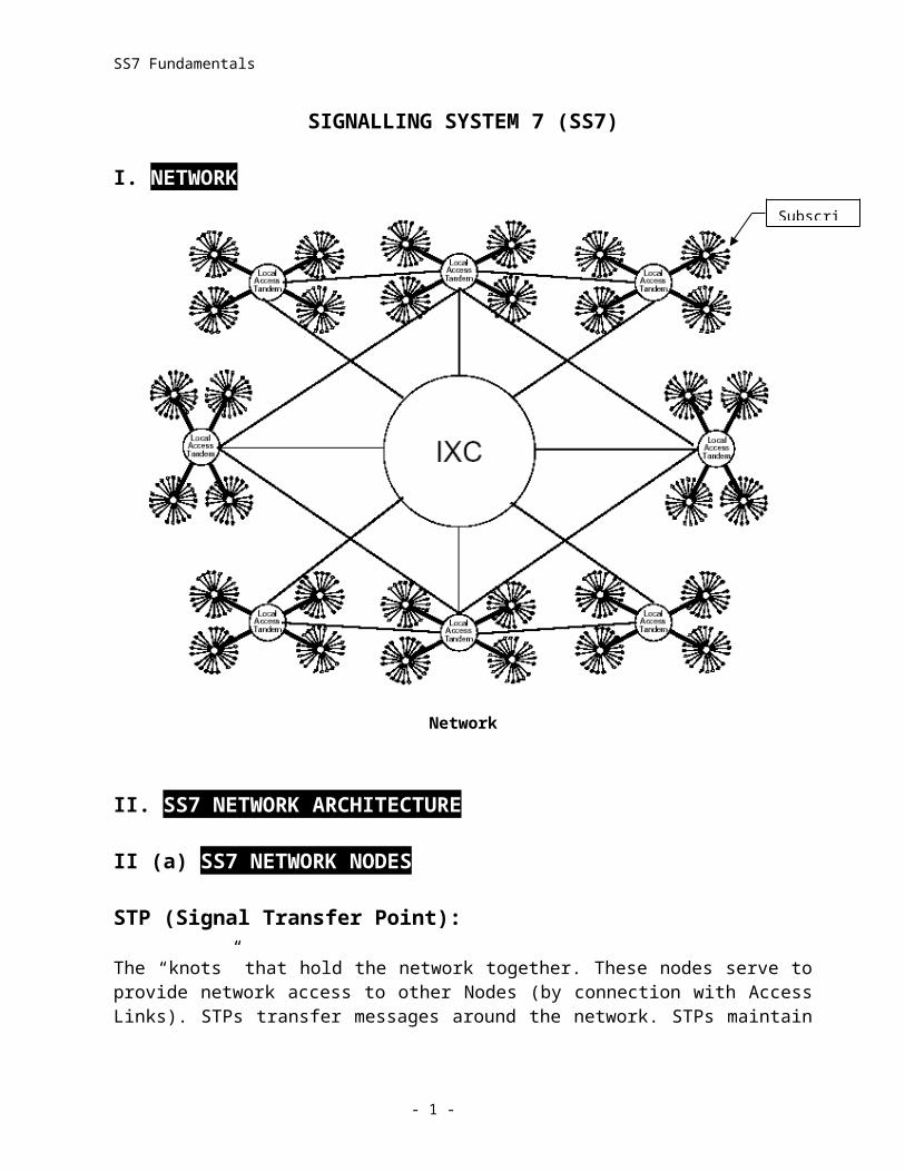
I. NETWORK
Network
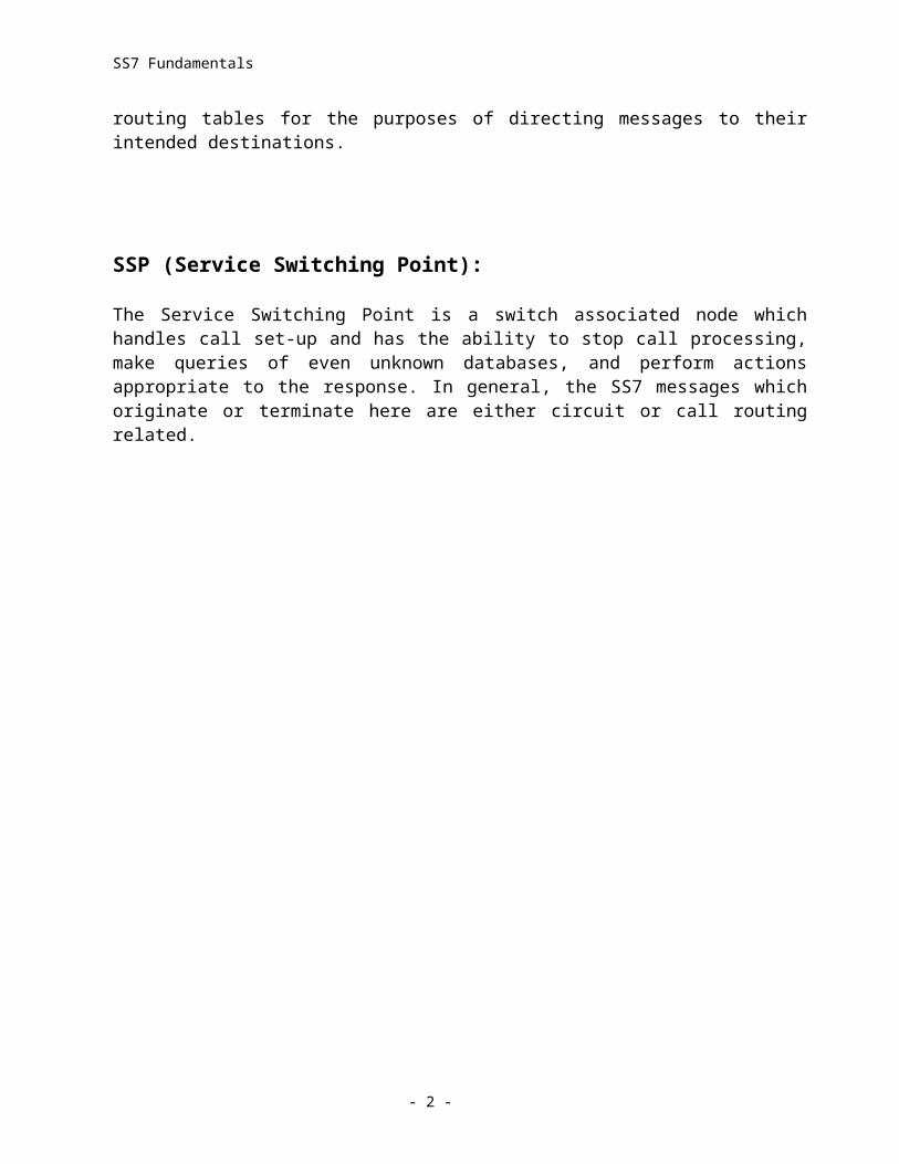
II. SS7 NETWORK ARCHITECTURE
II (a) SS7 NETWORK NODES
STP (Signal Transfer Point):
The “knots” that hold the network together. These nodes serve to provide network access to other Nodes (by connection with Access Links). STPs transfer messages around the network. STPs maintain routing tables for the purposes of directing messages to their intended destinations.
- 1 -
Subscriber
SS7 Fundamentals
SSP (Service Switching Point):
The Service Switching Point is a switch associated node which handles call set-up and has the ability to stop call processing, make queries of even unknown databases, and perform actions appropriate to the response. In general, the SS7 messages which originate or terminate here are either circuit or call routing related.
SS7 Network Architecture
SCP (Service Control Point):
In general, Service Control Points provide access to databases. These nodes are the residences of processes which can access the database extract the required data and return it to the node requesting the data. The database(s) to which the SCP has access may or may not reside at the
- 2 -
SS7 Fundamentals
same location as the SCP. The same capabilities that allow the SCP to access databases lend themselves to other uses such as providing access to an IP.
IP (Intelligent Peripheral):
The IP is the residence of processes which manage resources such as signalling sensors and voice response equipment. The resource management capabilities become available to switches on demand, thereby freeing switch locations from the need to equip with a myriad of such devices, and providing highly efficient use of both aging and up-to-date technologies.
CRP (Customer Routing Point):
The CRP provides on-premises control of the routing information requested by switches for translation of 800 type dialing (not limited to 800 numbers). The operator of the CRP is a customer who requires rapid update and control of the translation of their own numbers.
MSC (Mobile Switching Center):
The Mobile Switching Center maintains control over its own Transceiver network. Part of this control includes tracking subscribers and performing “hand offs.” The MSC also provides the landline connections into the PSTN to complete the connection of subscriber calls. Finally, the MSC makes use of the SS7 network to convey circuit related information to the PSTN and to communicate with the service providers of “roamers.”
HLR/VLR (Home Location Register/Visitor Location Register):
A database that contains customer information about local subscribers is maintained by each provider. This is the Home Location Register. Another company will access this information when a “roamer” appears, and use the data for an entry into its Visitor Location Register.
II (b) SS7 NETWORK LINKS
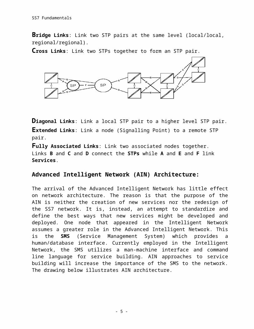
Access Links: Link a node (Signalling Point) to a local STP pair.
Bridge Links: Link two STP pairs at the same level (local/local, regional/regional).
Cross Links: Link two STPs together to form an STP pair.
- 3 -
SS7 Fundamentals
Diagonal Links: Link a local STP pair to a higher level STP pair.
Extended Links: Link a node (Signalling Point) to a remote STP pair.
Fully Associated Links: Link two associated nodes together.Links B and C and D connect the STPs while A and E and F link Services.
Advanced Intelligent Network (AIN) Architecture:
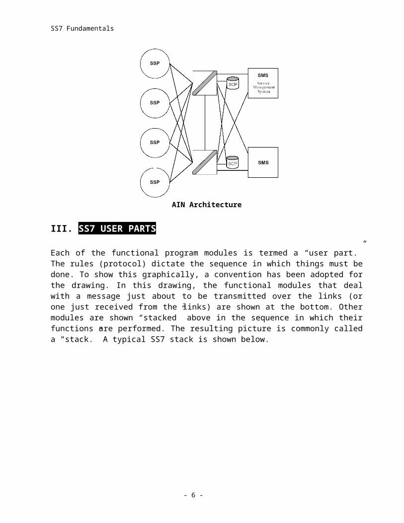
The arrival of the Advanced Intelligent Network has little effect on network architecture. The reason is that the purpose of the AIN is neither the creation of new services nor the redesign of the SS7 network. It is, instead, an attempt to standardize and define the best ways that new services might be developed and deployed. One node that appeared in the Intelligent Network assumes a greater role in the Advanced Intelligent Network. This is the SMS (Service Management System) which provides a human/database interface. Currently employed in the Intelligent Network, the SMS utilizes a man-machine interface and command line language for service building. AIN approaches to service building will increase the importance of the SMS to the network. The drawing below illustrates AIN architecture.
AIN Architecture
III. SS7 USER PARTS
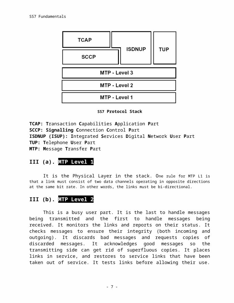
Each of the functional program modules is termed a “user part.” The rules (protocol) dictate the sequence in which things must be done. To show this graphically, a convention has been adopted for the drawing. In this drawing, the functional modules that deal with a message just about to be transmitted over the links (or one just received from the links) are shown at the bottom. Other modules are shown “stacked” above in the sequence in which their functions are performed. The resulting picture is commonly called a “stack.” A typical SS7 stack is shown below.
- 4 -
SS7 Fundamentals
SS7 Protocol Stack
TCAP: Transaction Capabilities Application PartSCCP: Signalling Connection Control PartISDNUP (ISUP): Integrated Services Digital Network User PartTUP: Telephone User PartMTP: Message Transfer Part
III (a). MTP Level 1
It is the Physical Layer in the stack. One rule for MTP L1 is that a link must consist of two data channels operating in opposite directions at the same bit rate. In other words, the links must be bi-directional.
III (b). MTP Level 2
This is a busy user part. It is the last to handle messages being transmitted and the first to handle messages being received. It monitors the links and reports on their status. It checks messages to ensure their integrity (both incoming and outgoing). It discards bad messages and requests copies of discarded messages. It acknowledges good messages so the transmitting side can get rid of superfluous copies. It places links in service, and restores to service links that have been taken out of service. It tests links before allowing their use. It provides sequence numbering for outgoing messages. And finally it reports much of the information it gathers to Level 3.
i) Signal Unit Delimitation and Alignment - User part functions vary with whether the message is being received or sent. This function is performed by Level 2 when a message is being sent out on a link. The user part attaches an 8 bit code to the beginning of a message package (an MSU, or Message Signal Unit). This code, termed a “flag”, always consists of a byte with zeros at each end and six “1s” in the middle. In ANSI networks a single (lead) flag is used. In CCITT networks, flags are placed at both the lead and trail ends of the Message Signal Unit.
- 5 -
SS7 Fundamentals
At the receiving end, level 2 reacts to this flag by resetting all resources used in the reading of messages. The result is that the flag indicates an appropriate position in the MSU to begin reading the message. Quite commonly, the normal coding of other information in the MSU would result in the creation of “imitation” flags. Such imitations would be read by the receiving MTP and interpreted as flags. To prevent this, the MTP on the side sending the message analyzes the entire MSU to find sequences of “1s.” When it locates a sequence of five “1s”, it places a “0” directly after it in a process known as “bit stuffing.” On the receiving side, the flag alerts the MTP to the beginning of a message. Thereafter, it simply removes a zero after each sequence of five ones, and the message is restored to its original form. An overly long message is considered “misaligned” and results in the MTP changing its method of counting Signal Unit errors.
ii) Signal Unit Error Detection - When sending a message, the MTP keeps track of the numbers of bits being transmitted in the Message Signal Unit. That number (less the 8 bits of the lead flag) is encoded using a check bits algorithm, and placed at the end of the MSU (before the final flag, if there is one). At the receiving end, level 2 counts the number of bits seen after the lead flag and decodes the check bits to determine if they are the same. If the check bits don’t equal the count made by the MTP, the message is discarded and a copy is requested.
iii) Signal Unit Error Correction - The standards support two methods of error correction. The type used depends on whether the transmission is land based or satellite based.
In the case of land based transmission, the transmitting side makes a copy of every message sent and retains the copy in a retransmit buffer. When the receiving MTP recognizes a corrupted message, it sends a request to the transmit side for message copies. The transmit side stops transmitting and begins delivery of the copies stored in the buffer instead. Message numbering that is applied to each transmitted message ensures the transmission of the correct messages in the correct sequence. Positive acknowledgment from the receiving MTP eventually indicates that the receiving side has caught up. At that point the transmitting side stops transmitting copies and returns to its normal ‘copy and send’ procedures.
For satellite transmission, the procedure is similar with one major exception. A limit is set on held copies. Once the limit is reached, transmission is stopped and the stored copies are transmitted repetitively until acknowledgments are received. This continues until the number of copies which remain unacknowledged reaches some pre-set lower threshold.
iv) Signalling Link Alignment - This functionality is invoked when a link is initially placed into service, and again when a link is being restored to service following a link failure. The procedure passes through four states, beginning with an Out-Of-Alignment state and ending with an error monitoring proving period. The standards provide for a choice of two proving procedures which can be imposed by the node. For either proving procedure, the MTP sends the simplest form of message format (the form known as Fill In Signal Unit, FISU) while maintaining a count of FISUs in error.
For the procedure known as Normal Alignment, the proving period lasts for 2.0 seconds and a maximum of four errors are allowed. For the procedure known as Emergency Alignment, the proving period lasts for 0.5 second and a maximum of one error is allowed. The time period is dependent on the transmission rate. The values given here are those of a standard 64Kbps.
- 6 -
SS7 Fundamentals
v) Alignment Error Rate Monitor (AERM) - During the alignment proving period, the MTP watches the FISUs to ensure that each contains an even multiple of 8 bits and is six octets long including the lead flag. The AERM is incremented for each time that this is not so.
vi) Signal Unit Error Rate Monitor (SUERM) - During normal transmission, the MTP watches Signal Units to ensure that each is an even multiple of 8 bits and is at least six octets long. “Ones density” is also checked (imitation flags) and the check bits are tallied against the actual Signal Unit length. Errors cause the SUERM to be incremented. When the error count reaches 64 the link is removed from service and the alignment procedure begins anew.
The SUERM is an increment/decrement counter designed to determine error rate rather than error count. Therefore, each time a series of 256 valid messages has been monitored, the SUERM is decremented. This method of determining an error rate is generally known as the “leaky bucket” technique.
vii) Flow Control - Level 2 monitors congestion on the links. How the sensing is to be accomplished is not specified in the standards. Generally, this is a matter of detecting message buildup at link associated message queues. When a threshold is passed, the MTP sends a Signal Unit back to the sending side to indicate SIB (Status Indicator Busy). The receiving side stops returning acknowledgments (both positive and negative).
The receiving side periodically retransmits the ‘Busy’ status indication and the transmitting side resets the timer for ‘Excessive Delay of Acknowledgment’ (T7). This means the transmit side continues to retain the copies in its retransmission buffer. Eventually, either the receiving side will stop sending ‘Busy’ or a second timer (T6) on the transmit side will time out and a ‘link failure indication’ will be generated.
- 7 -
SS7 Fundamentals
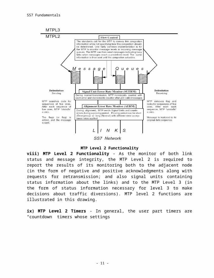
MTP Level 2 Functionalityviii) MTP Level 2 Functionality - As the monitor of both link status and message integrity, the MTP Level 2 is required to report the results of its monitoring both to the adjacent node (in the form of negative and positive acknowledgments along with requests for retransmission; and also signal units containing status information about the links) and to the MTP Level 3 (in the form of status information necessary for level 3 to make decisions about traffic diversions). MTP level 2 functions are illustrated in this drawing.
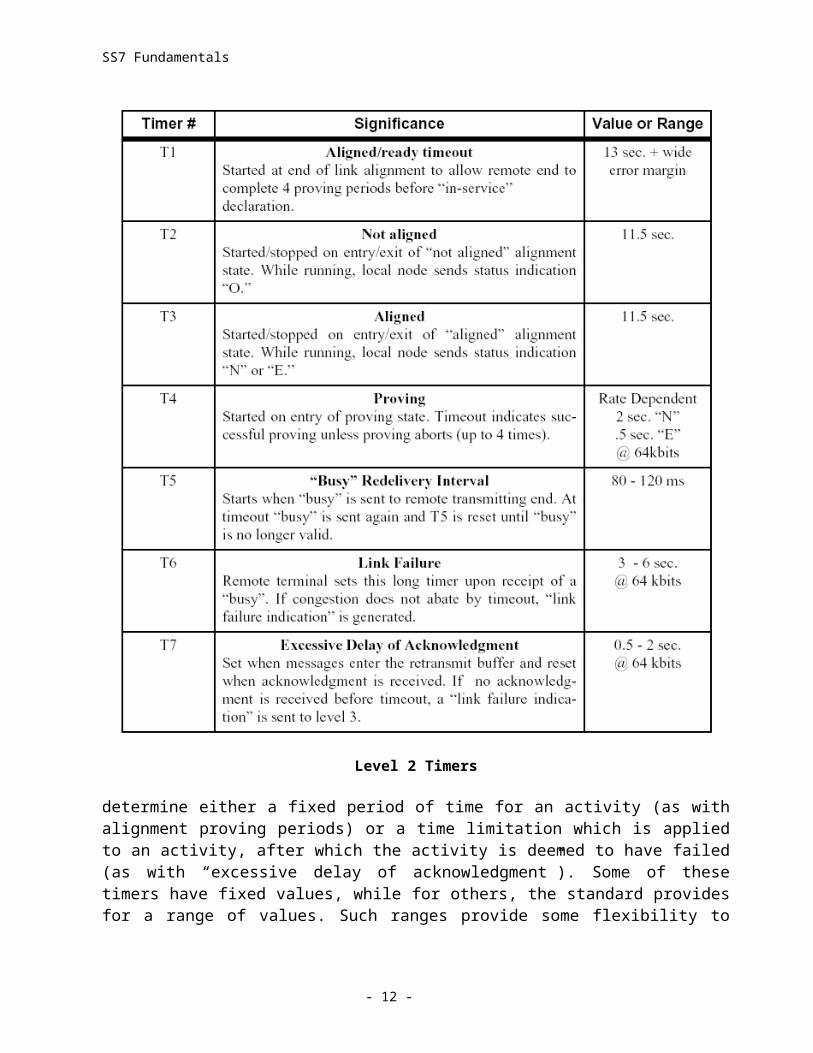
ix) MTP Level 2 Timers - In general, the user part timers are “countdown” timers whose settings
- 8 -
SS7 Fundamentals
Level 2 Timers
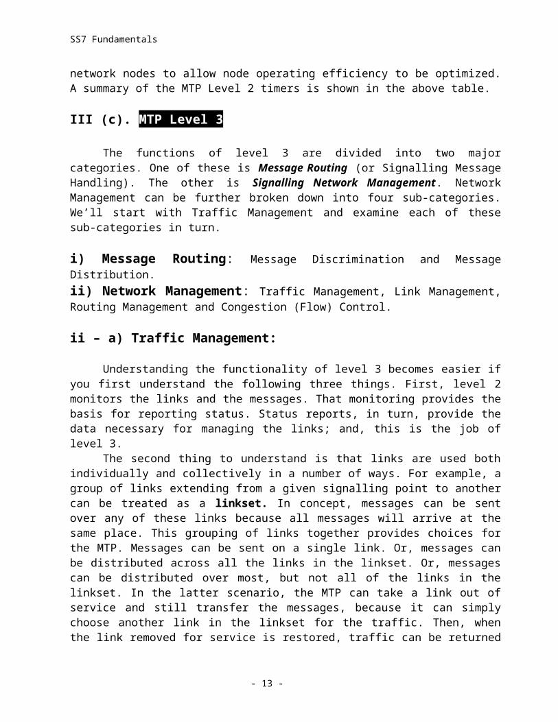
determine either a fixed period of time for an activity (as with alignment proving periods) or a time limitation which is applied to an activity, after which the activity is deemed to have failed (as with “excessive delay of acknowledgment”). Some of these timers have fixed values, while for others, the standard provides for a range of values. Such ranges provide some flexibility to network nodes to allow node operating efficiency to be optimized. A summary of the MTP Level 2 timers is shown in the above table.
III (c). MTP Level 3
- 9 -
SS7 Fundamentals
The functions of level 3 are divided into two major categories. One of these is Message Routing (or Signalling Message Handling). The other is Signalling Network Management. Network Management can be further broken down into four sub-categories. We’ll start with Traffic Management and examine each of these sub-categories in turn.
i) Message Routing: Message Discrimination and Message Distribution.ii) Network Management: Traffic Management, Link Management, Routing Management and Congestion (Flow) Control.
ii – a) Traffic Management:
Understanding the functionality of level 3 becomes easier if you first understand the following three things. First, level 2 monitors the links and the messages. That monitoring provides the basis for reporting status. Status reports, in turn, provide the data necessary for managing the links; and, this is the job of level 3.
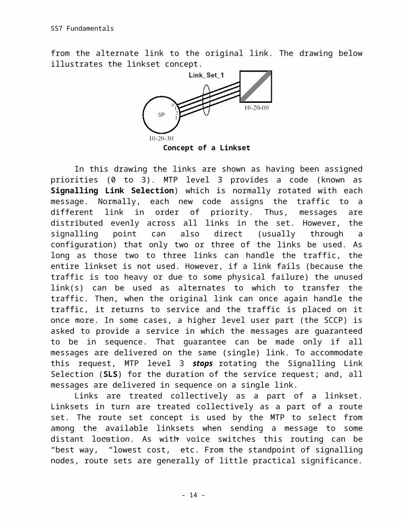
The second thing to understand is that links are used both individually and collectively in a number of ways. For example, a group of links extending from a given signalling point to another can be treated as a linkset. In concept, messages can be sent over any of these links because all messages will arrive at the same place. This grouping of links together provides choices for the MTP. Messages can be sent on a single link. Or, messages can be distributed across all the links in the linkset. Or, messages can be distributed over most, but not all of the links in the linkset. In the latter scenario, the MTP can take a link out of service and still transfer the messages, because it can simply choose another link in the linkset for the traffic. Then, when the link removed for service is restored, traffic can be returned from the alternate link to the original link. The drawing below illustrates the linkset concept.
Concept of a Linkset
In this drawing the links are shown as having been assigned priorities (0 to 3). MTP level 3 provides a code (known as Signalling Link Selection) which is normally rotated with each message. Normally, each new code assigns the traffic to a different link in order of priority. Thus, messages are distributed evenly across all links in the set. However, the signalling point can also direct (usually through a configuration) that only two or three of the links be used. As long as those two to three links can handle the traffic, the entire linkset is not used. However, if a link fails (because the traffic is too heavy or due to some physical failure) the unused link(s) can be used as alternates to which to transfer the traffic. Then, when the original link can once again handle the traffic, it returns to service and the traffic is placed on it once more. In some cases, a higher level user part (the SCCP) is asked to provide a service in which the messages are
- 10 -
SS7 Fundamentals
guaranteed to be in sequence. That guarantee can be made only if all messages are delivered on the same (single) link. To accommodate this request, MTP level 3 stops rotating the Signalling Link Selection (SLS) for the duration of the service request; and, all messages are delivered in sequence on a single link.
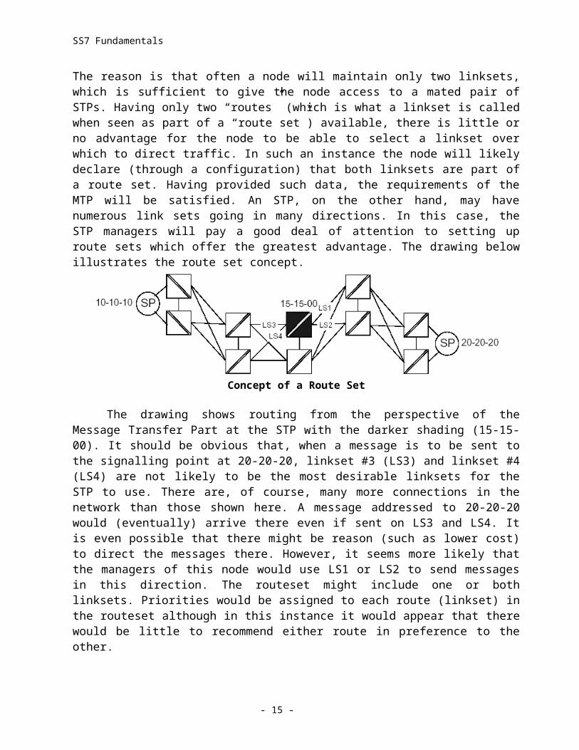
Links are treated collectively as a part of a linkset. Linksets in turn are treated collectively as a part of a route set. The route set concept is used by the MTP to select from among the available linksets when sending a message to some distant location. As with voice switches this routing can be “best way,” “lowest cost,” etc. From the standpoint of signalling nodes, route sets are generally of little practical significance. The reason is that often a node will maintain only two linksets, which is sufficient to give the node access to a mated pair of STPs. Having only two “routes” (which is what a linkset is called when seen as part of a “route set”) available, there is little or no advantage for the node to be able to select a linkset over which to direct traffic. In such an instance the node will likely declare (through a configuration) that both linksets are part of a route set. Having provided such data, the requirements of the MTP will be satisfied. An STP, on the other hand, may have numerous link sets going in many directions. In this case, the STP managers will pay a good deal of attention to setting up route sets which offer the greatest advantage. The drawing below illustrates the route set concept.
Concept of a Route Set
The drawing shows routing from the perspective of the Message Transfer Part at the STP with the darker shading (15-15-00). It should be obvious that, when a message is to be sent to the signalling point at 20-20-20, linkset #3 (LS3) and linkset #4 (LS4) are not likely to be the most desirable linksets for the STP to use. There are, of course, many more connections in the network than those shown here. A message addressed to 20-20-20 would (eventually) arrive there even if sent on LS3 and LS4. It is even possible that there might be reason (such as lower cost) to direct the messages there. However, it seems more likely that the managers of this node would use LS1 or LS2 to send messages in this direction. The routeset might include one or both linksets. Priorities would be assigned to each route (linkset) in the routeset although in this instance it would appear that there would be little to recommend either route in preference to the other.
Back where we started this discussion we said there were three things that needed to be understood about MTP level 3. The first is the nature of a linkset. The second is the nature of a routeset. The third is to understand that the MTP level 3 both reports adverse network situations and responds to those situations by redirecting traffic. The question is where is the MTP that does each of these? A service provider’s node (such as an SSP or a CRP) generally has links only to an STP pair. It therefore has little way of collecting information about the network beyond its links. The STP, on the other hand, maintains links to multiple service provider nodes as well as to other STPs. In general, then, the MTP at the service provider’s node will receive Route Management messages from the STP and will respond by diverting its outgoing traffic using Traffic and Link
- 11 -
SS7 Fundamentals
Management functionality. If the service provider’s node maintains enough links with enough access to the network, it may succeed in getting its messages around network trouble spots. Let’s see how the MTP at a location which is not an STP might attempt to do this.
!) Forced Rerouting - When an STP is unable to route to a specific signalling point in the network, it sends a Transfer Prohibited (TFP) signal to adjacent nodes. When an STP is unable to route to a specific signalling cluster in the network, it sends a Transfer Cluster Prohibited (TCP) signal to adjacent nodes. The level 3 User Part at the node responds by diverting traffic to another available linkset, then returning traffic to the original linkset when normal routing can be reestablished.
!!) Controlled Rerouting - When an STP encounters difficulty in routing to a specific signalling point in the network (but, transfer is possible), it sends a Transfer Restricted (TFR) signal to adjacent nodes. When an STP encounters difficulty in routing to a specific signalling cluster in the network (but, transfer is possible), it sends a Transfer Cluster Restricted (TCR) signal to adjacent nodes. The level 3 User Part at the node responds by diverting traffic to a more efficient linkset, then returning traffic to the original linkset when normal routing can be re-established.
!!!) MTP Restart - Before returning to the network, a node which has been isolated by the unavailability of its linksets needs time to determine any network routing changes which have occurred while it was not available. Before full startup it sends a TRW (Traffic Restart Wait) signal which lets adjacent nodes know not to send traffic even though the links may appear to have resumed service. When the restarting node is satisfied that “enough” links (usually 50%) are available Level 3 sends TRA (Traffic Restart Allowed).
!!!!) Management Inhibiting - This is a link labeling procedure which does not prevent link usage, but rather, reserves a link for the purpose of sending test messages. A link under congestion cannot be inhibited. If the link is the only one available for traffic, it cannot be inhibited. Finally, an inhibition request requires positive confirmation from the MTP at the other end.
ii – b) Link Management:
MTP level 3 directs the activities of placing links in and out of service. Instantaneous removal or replacement of links would leave no time for the adjacent (directly connected by link) nodes to react. The result would be lost, duplicated, or corrupted messages. Therefore the link management functionality enforces an orderly withdrawal and replacement of links through a mandatory message exchange.Link Management!) Signalling Link Activation - MTP level 3 directs the activation of the links (at the request of an application), deactivates links in response to changing link status, and reactivates links removed from service once those links can resume service.!!) Signalling Link Changeover - When traffic must be removed from a link taken from service and brought to another link, MTP level 3 controls the process to eliminate lost messages, duplication, or mis sequencing. It does so by warning the adjacent node through a Change Over Order (COO) signal and receives a Change Over Acknowledgment (COA) in response.
- 12 -
SS7 Fundamentals
!!!) Signalling Link Changeback - Traffic must be returned to a link from which it was diverted when that link is successfully realigned. MTP level 3 controls the process to eliminate lost messages, duplication, or mis sequencing. It does so by warning the adjacent node through a Change Back Declaration (CBD) signal and receives a Change Back Acknowledgment (CBA) in response.
!!!!) Signalling Link Test - A Signalling Link Test Message (SLTM) and a Signalling Link Test Acknowledgment (SLTA) are (optionally) exchanged immediately after alignment and periodically (30-90 sec.) while the link is in service. The message data ensures unified agreement about the Signalling Link Code used by both adjacent nodes to identify the link
ii – c) Routing Management:
It consists of procedures which are really the “flip side” of the Traffic Management procedures. Most of these are procedures performed by the MTP at an STP. The reason this is so is that it is the STP which has routing responsibilities in the SS7 network. As a result, it is the STP which receives most of the information about unavailable signalling points or signalling points experiencing difficulties (such as numerous congested links).
!) Transfer-Prohibited / Transfer-Cluster-Prohibited - An STP sends a Transfer Prohibited (TFP) signal to adjacent nodes when it is unable to route to a specific signalling point in the network; An STP sends a Transfer Cluster Prohibited (TCP) signal to adjacent nodes when it is unable to route to a specific signalling cluster in the network.
!!)Transfer-Restricted / Transfer-Cluster-Restricted - An STP sends a Transfer Restricted (TFR) signal to adjacent nodes when it encounters difficulty in routing to a specific signalling point in the network (but, transfer is possible); An STP sends a Transfer Cluster Restricted (TCR) signal to adjacent nodes when it encounters difficulty in routing to a specific signalling cluster in the network (but, transfer is possible).
!!!) Transfer-Allowed / Transfer-Cluster-Allowed - These messages (TFA & TCA) are sent by the STP to the adjacent nodes when the condition which caused it to send the restricted or prohibited messages has been cleared.
!!!!) Signalling-Route-Set-Test - Nodes generally respond to Route Management Messages sent by STPs by invoking local link management signals like Change Over Order (COO). In addition, the affected node will send a periodic Signalling-Route-Set-Test (SRST) to check the routing status. The typical sending interval is 30 seconds.
ii – d) Congestion (Flow) Control:
At some point in time you may be reading through the standards and end up with some confusion about whether flow control is a level 2 or level 3 function. You can limit this confusion by remembering that level 2 is responsible for monitoring and reporting the results of the
- 13 -
SS7 Fundamentals
monitoring. Level 3, on the other hand, uses this information to manage developing problems by causing link, linkset, or route set diversions and also by reporting to the upper levels.
In the case of flow control, the MTP level 2 must first determine whether congestion exists; and, if it does, to report how bad the congestion is. When congestion occurs at the receiving end, MTP level 2 sends a congestion indication over the link in question to the MTP at the transmitting side. The receiving MTP also stops sending the acknowledgments that would allow the transmitting node to eliminate successfully transmitted messages from its retransmit buffer. Also, at the transmitting node, a long timer is started, which, when it expires, will provide a “link failure indication.”
One of the clearest indications of congestion is the buildup of messages in the transmit and retransmit buffers of the sending node. The standards provide for threshold values to be imposed upon the amount of messaging in the transmit and/or retransmit buffers. Whether the event sensing is placed at the transmit buffer, the retransmit buffer, or both is based on the relative sizes of both. Three identical sets of event values are set for three overlapping message levels. Each level has a congestion onset value, a congestion abatement value, and a discard onset value. When the first congestion onset is reached, the MTP level 2 will inform MTP level 3. Level 3 responds by informing the user part sending the messages (SCCP, ISUP, TUP etc.). If the buildup of messages continues, it will reach the discard onset threshold. When this occurs level three begins to discard messages.
A message can be assigned a priority. Messages containing only information of a non-critical nature are assigned the lowest priority. This priority value corresponds to the level of congestion indicated when the lowest congestion onset threshold is reached. Because this is so, the messages that are discarded when the lowest discard onset threshold is reached are the lowest priority messages. If the message buildup falls below a threshold which has been set lower than that of congestion onset, the MTP will stop reporting congestion. This is called the congestion abatement threshold. If the congestion buildup continues despite discard of low priority messages, it will eventually reach congestion onset at the next highest level. The MTP will indicate a higher level of congestion. Then, if the discard onset threshold is reached, the MTP will discard the messages of the next higher priority. At the same time it will still be discarding low priority messages. This escalation of congestion level along with the discard of higher priority messages continues for three priority levels. The standards support the assignment of four priorities. However, only three levels of Flow Control message discard are assigned because the highest priority is given to network management messages with the understanding that such messages are not subject to discard.
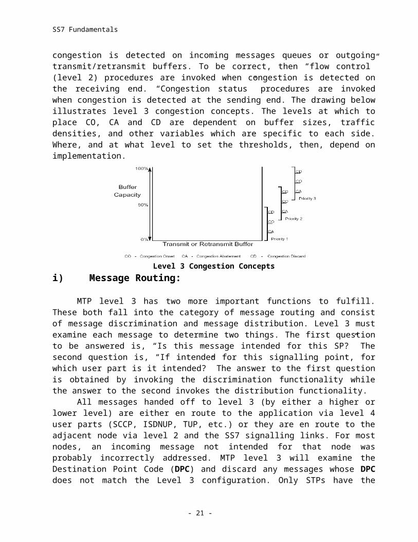
The job of level 2 is to monitor and report (both to level 3 and to the MTP at the other end of the links). The job of level 3 is to manage (as with links, link sets and routes) and to report to higher level user parts. Congestion status, traffic control, route and link management, status indicating and flow control, are therefore all interrelated. The distinction between level2 and level 3 congestion issues is largely a matter of whether congestion is detected on incoming messages queues or outgoing transmit/retransmit buffers. To be correct, then “flow control” (level 2) procedures are invoked when congestion is detected on the receiving end. “Congestion status” procedures are invoked when congestion is detected at the sending end. The drawing below illustrates level 3 congestion concepts. The levels at which to place CO, CA and CD are dependent on buffer sizes, traffic densities, and other variables which are specific to each side. Where, and at what level to set the thresholds, then, depend on implementation.
- 14 -
SS7 Fundamentals
Level 3 Congestion Concepts
i) Message Routing:
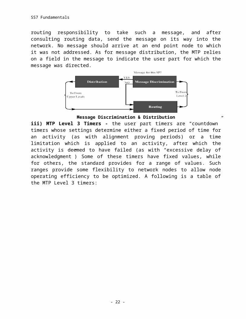
MTP level 3 has two more important functions to fulfill. These both fall into the category of message routing and consist of message discrimination and message distribution. Level 3 must examine each message to determine two things. The first question to be answered is, “Is this message intended for this SP?” The second question is, “If intended for this signalling point, for which user part is it intended?” The answer to the first question is obtained by invoking the discrimination functionality while the answer to the second invokes the distribution functionality.
All messages handed off to level 3 (by either a higher or lower level) are either en route to the application via level 4 user parts (SCCP, ISDNUP, TUP, etc.) or they are en route to the adjacent node via level 2 and the SS7 signalling links. For most nodes, an incoming message not intended for that node was probably incorrectly addressed. MTP level 3 will examine the Destination Point Code (DPC) and discard any messages whose DPC does not match the Level 3 configuration. Only STPs have the routing responsibility to take such a message, and after consulting routing data, send the message on its way into the network. No message should arrive at an end point node to which it was not addressed. As for message distribution, the MTP relies on a field in the message to indicate the user part for which the message was directed.
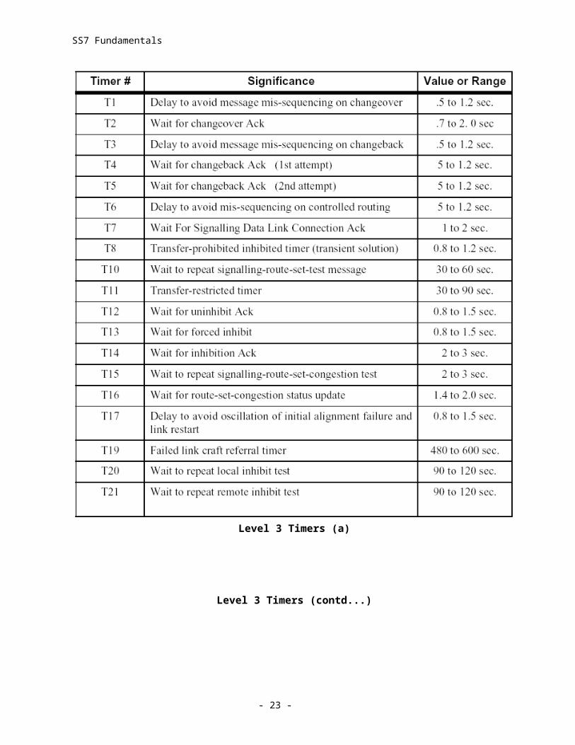
Message Discrimination & Distributioniii) MTP Level 3 Timers - the user part timers are “countdown” timers whose settings determine either a fixed period of time for an activity (as with alignment proving periods) or a time limitation which is applied to an activity, after which the activity is deemed to have failed (as with “excessive delay of acknowledgment”) Some of these timers have fixed values, while for others, the standard provides for a range of values. Such ranges provide some flexibility to network nodes to allow node operating efficiency to be optimized. A following is a table of the MTP Level 3 timers:
- 15 -
SS7 Fundamentals
Level 3 Timers (a)
Level 3 Timers (contd...)
- 16 -
SS7 Fundamentals
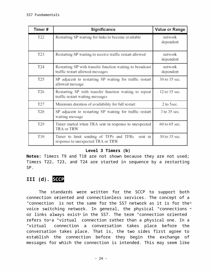
Level 3 Timers (b)Notes: Timers T9 and T18 are not shown because they are not used; Timers T22, T23, and T24 are started in sequence by a restarting SP.
III (d). SCCP
The standards were written for the SCCP to support both connection oriented and connectionless services. The concept of a “connection” is not the same for the SS7 network as it is for the voice switching network. In general, the physical “connections” or links always exist in the SS7. The term “connection oriented” refers to a “virtual” connection rather than a physical one. In a “virtual” connection a conversation takes place before the conversation takes place. That is, the two sides first agree to establish the connection before they begin the exchange of messages for which the connection is intended. This may seem like overkill. The idea is to make the rules of communication more rigid in order to better guarantee the integrity of the communication. The phases of such a connection resemble those of a telephone call. The phone call consists of a setup phase followed, by a voice conversation, followed by a release phase. A “virtual connection” consists of a connection establishment phase followed by a data transfer phase, followed by a connection release phase. Connection oriented services tend to use more resources and create greater “overhead.” The trade-off for increased integrity is lower “speed.” In other words, even though the data transfer rates are the same for connectionless service, less
- 17 -
SS7 Fundamentals
significant data is passed per unit of time. Service providers have generally found connectionless services to be highly reliable with little tendency toward corruption; and, have, therefore opted not to make use of connection oriented services.
The service types offered by the SCCP are shown below along with the functions of the user part.
i) Service types: Class 0 Connectionless & Class 1 Connectionlessii) Extended Functions: Specialized Routing Functions & Subsystem Management
i) SCCP Service Types:
Both services shown here are connectionless. Essentially connectionless means that messages are simply delivered to their destination and returned to the point of origination without any additional special handling. No virtual connection is established. For class 0 usage, messages are transported without reference to other messages. Delivery of messages is not guaranteed to be sequential. On the other hand, for class 1, the SCCP calls on the services of MTP level 3 to modify its normal handling of links in link sets. MTP level 3 normally provides a rotating code value (Signalling Link Selection or SLS) to share the load in a link set. When asked to do so by SCCP, the MTP stops rotating this code. The result is that the SLS stays the same, message after message. Messages delivered on the same link remain in sequence.
ii – a) SCCP Specialized Routing Functions:
Many of the chief benefits of the use of the SCCP lie in the specialized routing functions. The addressing capabilities here are what allow the locating of database information or the invoking of features at a switch. To this point we have seen only the addressing capabilities of the MTP. The MTP, of course, is concerned only with transferring messages to the other end of links. For this reason its addressing is limited to the use of the point code of the location to which the link goes. The MTP deals only with the signalling point code of its own location in the network (which becomes its Origination Point Code), and the signalling point code of the node at the other end of the link (which becomes its Destination Point Code).
Destination Point Code (DPC) is important to the SCCP as well. When supplied by the originator of a query it indicates a network location where there is a process to retrieve data from a database (or where a service or feature can be invoked). However, it may be that data can be retrieved from more than one database at that location. For this reason, SCCP needs to provide addressing which can be used to differentiate between databases or between various features or services that can be invoked at a node. The value used is called a subsystem number.
The values provided for database identification range from 0 to 255. As of 1996, some of these were assigned to the most common usages. The “0” value, if used, indicates an “unknown” database. The first seven values are assigned for uses of the databases required for such things as the ISDN/Telephony Numbering Plan (1), The Data Numbering Plan (3), the Land Mobile Numbering Plan (6), etc. With the exception of some reserved (for future use) values, the remainder can be used. The SCCP uses DPC and SSN (subsystem number) to route to the appropriate network location and to the appropriate database which can be accessed at that location. Still another addressing mechanism is available to SCCP users. This one is known as Global Title Translation (GTT).
- 18 -
SS7 Fundamentals
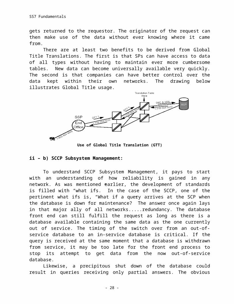
To understand the need for such a mechanism, let’s examine what happens at an SSP when someone dials an 800 number. Ordinarily, the dialed digits received at the switch would contain an area code, an exchange code, and a line number. The switch could then consult its routing table and determine the next switch through which to route the call. An 800 number, on the other hand, does not comply with the North American Numbering Plan which the switch would normally refer to in choosing the routing. The telephone being called is connected by voice line to an end office somewhere. That end office has an address in the North American Numbering Plan and the line to the telephone has a line number. Therefore, the telephone has a regular telephone number to which the switch (at the SSP) could route the call. Of course, every switch in the country could maintain an 800 number database for the purpose of translating the dialed digits of an 800 number into a normal telephone number. In this case, possible and practical is not the same thing. If it were done this way, every switch in the country would find it necessary to update its routing table every day.
There is a better way. If the switch simply maintains a database which provides it with the Destination Point Code and Subsystem Number of a centralized 800 database, it can send a query there and receive a normal telephone number in return. Now it can handle the call as if a normal telephone number were dialed in the first place. With the rate at which databases proliferate, it is only a matter of time before each switch will be maintaining a database of databases that will need frequent updating. This is one of the problems solved by GTT. Using GTT, the SSP need not know where the database is located. Instead, it makes a request for a Global Title translation and passes it on to the STP. The STP may have the DPC and SSN of the database in its own tables. If so, it redirects the request and later returns the data to the Point Code making the original request. If the first STP does not have the necessary address, it will usually have the location of another STP (perhaps at a different level of hierarchy) to which it can pass the Global Title request. When an STP which has access to the data is reached, it can retrieve the data and send it back to the location which was the one that sent the request to its final STP destination. Node by node, the data gets returned to the requestor. The originator of the request can then make use of the data without ever knowing where it came from.
There are at least two benefits to be derived from Global Title Translations. The first is that SPs can have access to data of all types without having to maintain ever more cumbersome tables. New data can become universally available very quickly. The second is that companies can have better control over the data kept within their own networks. The drawing below illustrates Global Title usage.
Use of Global Title Translation (GTT)
ii – b) SCCP Subsystem Management:
- 19 -
SS7 Fundamentals
To understand SCCP Subsystem Management, it pays to start with an understanding of how reliability is gained in any network. As was mentioned earlier, the development of standards is filled with “what ifs.” In the case of the SCCP, one of the pertinent what ifs is, “What if a query arrives at the SCP when the database is down for maintenance?” The answer once again lays in that major ally of all networks.....redundancy. The database front end can still fulfill the request as long as there is a database available containing the same data as the one currently out of service. The timing of the switch over from an out-of-service database to an in-service database is critical. If the query is received at the same moment that a database is withdrawn from service, it may be too late for the front end process to stop its attempt to get data from the now out-of-service database.
Likewise, a precipitous shut down of the database could result in queries receiving only partial answers. The obvious answer is to plan a shutdown period in such a way that the database goes out-of-service only after those who need the data have been informed of the impending lack of accessibility. Likewise, those who are normally accessing the data need time to switch to an alternate database.
Generally, when a replicated subsystem needs to leave service, the SCCP database is examined for “Concerned Points”. Such a point is a location which has to be informed of subsystem status because it is a location normally accessing data from the database in question. There are a number of ways in which replicated (multiply copied) databases can be implemented. Whichever way is used, the “Concerned Point” will generally have access to the data from a redundant source. The withdrawing database will make an effort to acquire agreement for the withdrawal from the redundant database by sending an N-Coord request primitive to the local SCCP. The local SCCP, in turn, sends a Subsystem-Out-of-Service-Request to the SCCP at the location of the redundant database. At the same time it sets a timer to wait for permission to be granted. If the timer times out before permission is granted, the local SCCP sends an N-Coord confirmation primitive back to the subsystem which indicates “denied”.
At the redundant database, the availability of resources (replicated database, traffic handling capabilities, etc.) is checked. If the resources are sufficient for the abandoned query/response load to be handled, an N-Coord response primitive is sent to the SCCP at the location of the database which requested permission to withdraw; and the request is granted. The SCCP broadcasts messages to the Concerned Points found in its configuration information. When a database is withdrawn from service “Subsystem-Prohibited” is broadcast to its CPs.
When the same database returns to service, the SCCP broadcasts “Subsystem-Allowed.” The same messages should be sent to the mated database to keep the replicate informed of the status of the database whose load it is now handling. When the “Subsystem-Prohibited” is received at the CP, the local SCCP sets a timer. When the timer times out a “Subsystem - Status - Test” is sent to the SCCP peer at the Out-of-Service location. The timer is reset when the message is sent and the cycle begins anew. “Subsystem-Status-Test” is no longer sent after the database returns to service. “Subsystem-Status-Test” (SST) is a request for the prohibited database The SST will repeat until an “allowed’ response is received. This guarantees that resources can be returned to their original state as soon as possible.
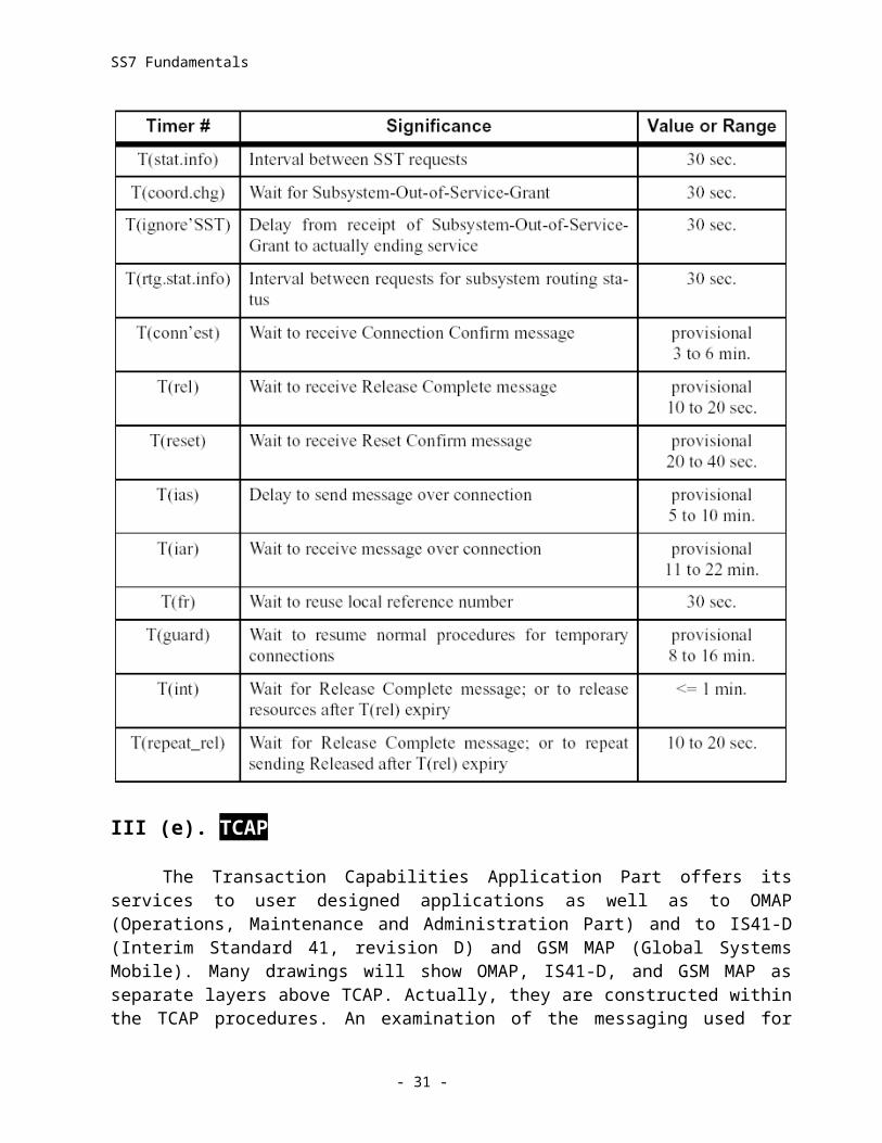
iii) SCCP Timers: In general, SCCP timers are used to coordinate Subsystem Management and to coordinate connection establishment and release.
- 20 -
SS7 Fundamentals
III (e). TCAP
The Transaction Capabilities Application Part offers its services to user designed applications as well as to OMAP (Operations, Maintenance and Administration Part) and to IS41-D (Interim Standard 41, revision D) and GSM MAP (Global Systems Mobile). Many drawings will show OMAP, IS41-D, and GSM MAP as separate layers above TCAP. Actually, they are constructed within the TCAP procedures. An examination of the messaging used for each would reveal what appear to be variations on TCAP. It would be accurate to say that the purpose of TCAP is to allow applications to exchange information using signalling that is not circuit related. It would also be accurate to say that TCAP is used largely by switching locations to obtain data
- 21 -
SS7 Fundamentals
from databases (SSP from 800 Db, MSC from HLR, etc.), or to invoke features at another switch (like Automatic Callback or Automatic Recall). Using the mobile message transports (GSM, IS41-D) also provides the procedures for database updating by reference to another database. In the Mobile network, for example, those who “roam” out of the network maintained by the company they pay for the service are tracked by the company into whose area they wander by transferring data from database to database. In this case the “Home Location Register” (HLR) is accessed by the new company and information is transferred into the new company’s “Visitor Location Register” (VLR).
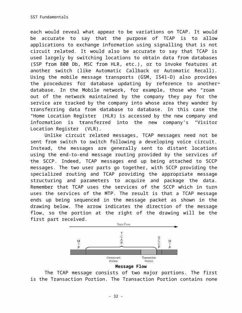
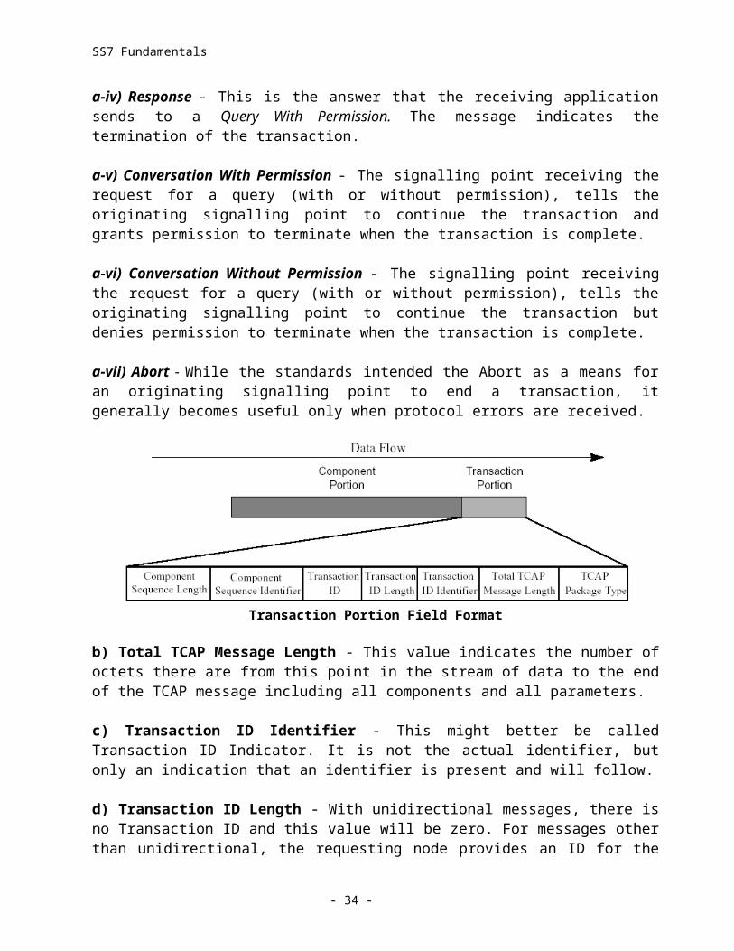
Unlike circuit related messages, TCAP messages need not be sent from switch to switch following a developing voice circuit. Instead, the messages are generally sent to distant locations using the end-to-end message routing provided by the services of the SCCP. Indeed, TCAP messages end up being attached to SCCP messages. The two user parts go together, with SCCP providing the specialized routing and TCAP providing the appropriate message structuring and parameters to acquire and package the data. Remember that TCAP uses the services of the SCCP which in turn uses the services of the MTP. The result is that a TCAP message ends up being sequenced in the message packet as shown in the drawing below. The arrow indicates the direction of the message flow, so the portion at the right of the drawing will be the first part received.
Message FlowThe TCAP message consists of two major portions. The first is the Transaction Portion.
The Transaction Portion contains none of the data of the message. Instead, it consists largely of protocol control. It begins with an octet (TCAP Package Type) that identifies the type of dialog that is to take place. Following the package type, the transaction portion indicates how many octets of data are contained in the entire message. It then deals (in housekeeping terms) with a Transaction ID. The transaction id is a value which is assigned to a complete query/response dialog and remains the same for the duration of the dialog. The reason this is necessary is that the application which is the originator of the query may have numerous queries out at one time. Some of those queries may be brief, single package transactions. Others may be multi-package transactions segmented to fit by the SCCP. Either way, the originator of the request needs to be able to correlate the query with the response information. That correlation is provided by an identifying value generated with the query and returned with all data associated with the response.
i) Transaction Portion Fields
a) TCAP Package Type - This field is filled in by the signalling point making the request to let the receiver know the nature of the request. It also contains the data necessary to relate this message to other messages which may be part of the same continuing transaction. Here are the types used.
- 22 -
SS7 Fundamentals
a-i) Unidirectional - A one way message with no reply expected.
a-ii) Query With Permission - The signalling point making the request does not expect to use the same transaction to send other messages. It therefore grants the receiving application permission to release allocated resources after responding.
a-iii) Query Without Permission - The signalling point making the request does expect to use the same transaction to send other messages. It therefore denies the receiving application permission to release allocated resources after responding.
a-iv) Response - This is the answer that the receiving application sends to a Query With Permission. The message indicates the termination of the transaction.
a-v) Conversation With Permission - The signalling point receiving the request for a query (with or without permission), tells the originating signalling point to continue the transaction and grants permission to terminate when the transaction is complete.
a-vi) Conversation Without Permission - The signalling point receiving the request for a query (with or without permission), tells the originating signalling point to continue the transaction but denies permission to terminate when the transaction is complete.
a-vii) Abort - While the standards intended the Abort as a means for an originating signalling point to end a transaction, it generally becomes useful only when protocol errors are received.
Transaction Portion Field Format
b) Total TCAP Message Length - This value indicates the number of octets there are from this point in the stream of data to the end of the TCAP message including all components and all parameters.
c) Transaction ID Identifier - This might better be called Transaction ID Indicator. It is not the actual identifier, but only an indication that an identifier is present and will follow.
d) Transaction ID Length - With unidirectional messages, there is no Transaction ID and this value will be zero. For messages other than unidirectional, the requesting node provides an ID for the purpose of correlating the query with the response. Such an ID will be four octets long. Sometimes a component will be sent to the originating node by the responding node and a reply is
- 23 -
SS7 Fundamentals
expected. In such instances, the responding node fills in both the original (requesting) Transaction ID and one provided by its own application. The dual IDs are, obviously, longer than a single ID.
e) Transaction ID - This is the actual value assigned to the transaction for the purpose of providing the correlation between queries sent and responses received. Generally, the ID is provided by the originator of the message. However, a second ID can be provided by the receiver when it finds it necessary to send a message back to the originator and anticipates a response.
f) Component Sequence Identifier - This value indicates the sequence of components to follow without indicating the actual number of components. While in the Transaction Portion, this code is generally considered to be part of a header for the component portion.
g) Component Sequence Length - This is the final field before the component portion. It indicates the length of the message beginning with the first field of the component portion and ending with the last parameter of the last component.
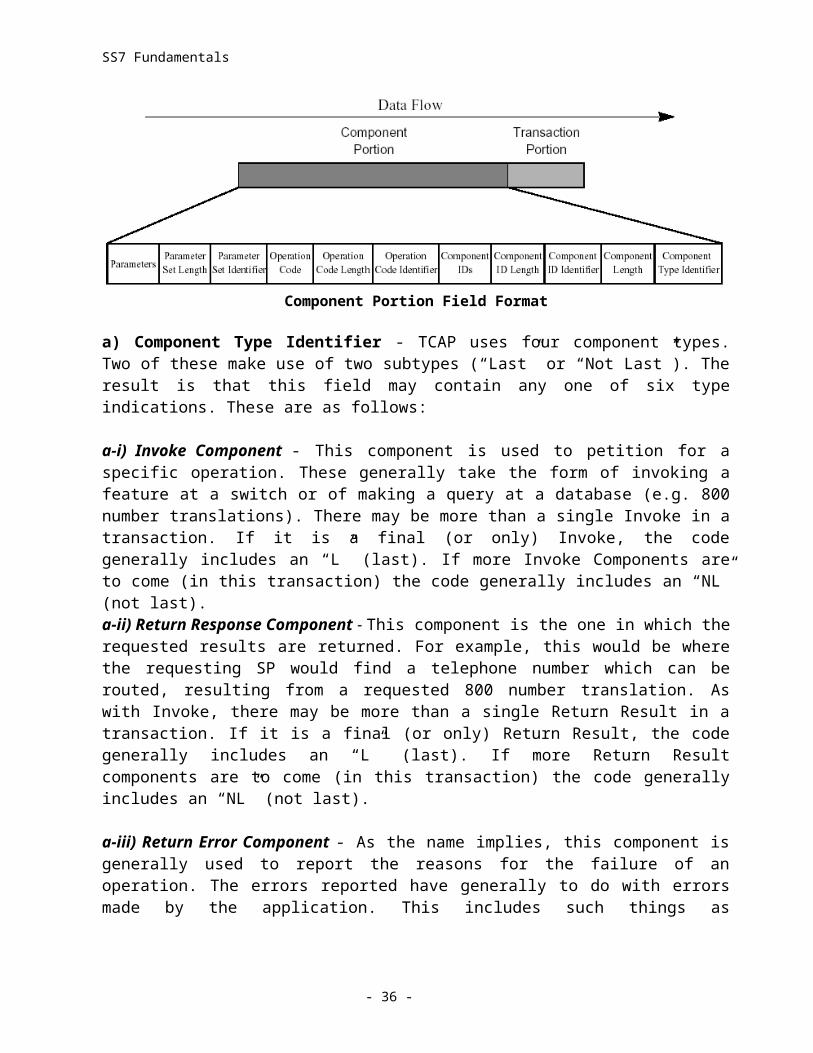
ii) Component Portion Fields
The drawing below illustrates the fields of the Component Portions. Invoke Component Fields are shown. The Operation Code Fields are replaced by other fields in different components.
Component Portion Field Format
a) Component Type Identifier - TCAP uses four component types. Two of these make use of two subtypes (“Last” or “Not Last”). The result is that this field may contain any one of six type indications. These are as follows:
a-i) Invoke Component - This component is used to petition for a specific operation. These generally take the form of invoking a feature at a switch or of making a query at a database (e.g. 800 number translations). There may be more than a single Invoke in a transaction. If it is a final (or only) Invoke, the code generally includes an “L” (last). If more Invoke Components are to come (in this transaction) the code generally includes an “NL” (not last).a-ii) Return Response Component - This component is the one in which the requested results are returned. For example, this would be where the requesting SP would find a telephone number which can be routed, resulting from a requested 800 number translation. As with Invoke, there may be more than a single Return Result in a transaction. If it is a final (or only) Return Result,
- 24 -
SS7 Fundamentals
the code generally includes an “L” (last). If more Return Result components are to come (in this transaction) the code generally includes an “NL” (not last).
a-iii) Return Error Component - As the name implies, this component is generally used to report the reasons for the failure of an operation. The errors reported have generally to do with errors made by the application. This includes such things as inconsistent use of IDs, unexpected results, or invalid parameters.
a-iv) Reject Component - This component is also used for error reporting. However, in this instance errors are attached to an indication of which part of the message contained the error. They may be reported as having occurred in the Transaction portion or in any of the other three components.
b) Component Length - This field indicates the length (in octets) of the component in which it is found. The component portion may consist of multiple components, each of which will have its own length indicator.
c) Component ID Identifier - The presence of this identifier indicates that this component has an Invoke ID or that another ID is added for the purpose of correlation of Invokes with Return Results. If sent by the originator, the value will be used in the Return Response (or any of the other components) returned. Note that this is separate from Transaction IDs because Transactions can involve more than one Invoke.
d) Component ID Length - The length indicated here is that of the ID field. This is used because the ID field length will vary from 0 for a Unidirectional message, to 4 or 8 depending on whether the ID represents an Invoke ID only, or a combination of an Invoke ID and a correlation ID.
e) Component IDs - In this field there may be an (optional) ID assigned to an Invoke component. This is not a network requirement and, when used, is significant only to the sender of the Invoke. When an Invoke ID is sent, a correlation ID becomes mandatory for the SP returning components to use the correlation value with any component returned which is in response to that Invoke.
f) The Fields Between Component IDs and Parameter Identifiers - In the next section we will discuss the Operation Code fields which were illustrated in the previous drawing. In the Return Result Component, these fields are missing entirely. In the Return Error Component, these fields are replaced by Error Code Identifier, Error Code Length and Error Code Fields. In the Reject Component these fields are replaced by Problem Code Identifier, Problem Code Length and Problem Code Fields.
g) Operation Code Identifier - This field carries an identifier for the National or for Private TCAP Networks. In the U.S., ANSI and Bellcore standards are implemented in the National network. Private networks may use their own coding internally, but any communications with other networks (e.g. the PSTN) must be ANSI compatible.
- 25 -
SS7 Fundamentals
h) Operation Code Length - This field indicates the length of the operation code only. For the National TCAP network the value is always 2 (octets). No such limitation applies to Private networks.
i) Operation Code - Operation codes are not specified in world wide standards. They are, instead, considered to be implementation dependent. Generally, they are used to specify the operation and how it is to be carried out. Most often, they are separated into categories such that one portion of the code will indicate a family of operations while another provides specifics.
j) Parameter Set Identifier - This is a single octet field which identifies the individual types of parameters. For example, this might be a timestamp, digits, or a network identifier.
k) Parameter Set Length - The length of the Parameters field is variable. Its actual length is indicated by this field.
l) Parameters - This field contains the actual parameter values. For example, if the Identifier indicated a timestamp, these fields would contain grouping of octets which would give the year (2 octets), the month (2 octets), the day (2 octets), the hour (2 octets), and the minutes (2 octets) all in binary. Following this there might also be fields expressing the difference between local time and Greenwich Meridian Time. The term “Parameter Set” used here refers to the fact that Parameters are grouped by specific data types. The examples here were all of the use of the “timestamp” set. Others (such as the “digits” set) contain data grouped by different data categories. Not all parameters in a set must be used. Operation codes can indicate which values are to be selected, thereby creating a “Parameter Set” which is specific to this component.
III (f). ISUP
The Integrated Services Digital Network User Part (ISDNUP) is usually thought of as being composed of standards referring to switch-to-switch circuit related messaging (ISUP), ISUP is used throughout the PSTN (Public Switched Telephone Network) to provide the messaging necessary for the set up and teardown of all circuits, both voice and digital. Wireless networks also make use of ISUP to establish the necessary switch connections into the PSTN. In the telephone network ISUP messages follow the path of the voice circuits. That is, ISUP messages are sent from each switch to the switch where the next circuit connection is required. ISUP offers two types of services, known as Basic and Supplementary. Basic Services consist of those services employed in the process of setting up and tearing down a call. Supplementary Services consist of those services employed in passing all messages that may be necessary to maintain and/or modify the call.
ISUP functionality can be further broken down into three procedural categories. The first of these is Signalling Procedure Control (SPRC) which directly interfaces with the services of the MTP. The SPRC, in turn, provides support for Circuit Supervision Control (CSC) and for Call Processing Control (CPC). The application, which deals with the circuit connection requirements of the switch, and simultaneously with SS7 signalling, is usually referred to as a Call Control application. The drawing below illustrates the architecture of ISUP procedures.
- 26 -
SS7 Fundamentals
ISUP Procedures
i) Basic Services - Call Setup:
ISUP protocol is employed in the process of setting up and tearing down a call (referred to as Basic Services) and in passing all of those messages which may be necessary to maintain and/or modify the call (referred to as Supplementary Services). For our purposes here we will assume analog lines in use between the connected parties and the telephone company. One of the easiest ways to understand ISUP messaging is to follow a scenario of the process involved in making a simple telephone call.
At the beginning of the process the calling party lifts the phone off the receiver. This places a current on the subscriber line interface of the local exchange. This is DC signalling. The local company acknowledges the presence of that current by sending a dial tone to the calling party. Having heard the dialtone, the calling party dials the phone, thereby sending the address (telephone number) of the called party to the local exchange. The local exchange waits until all digits have been dialed, and then examines the digits to see if the called party is local (no area code) or whether the call must be routed through a long distance carrier. If the call is long distance, the call will be routed to the long distance carrier through a point-of-presence (POP) in the Local Access Transport Area (LATA) of the calling party. The prefix and subscriber number (last four digits) will be used in the first message (IAM) routed to the distant exchange.
The call setup is sent using the ISUP protocol through the SS7 network. The STP is used to route this message, and beyond that, plays no significant role in setting up the voice circuits. Once all of this information has been collected, the originating exchange creates an Initial Address Message (IAM) and sends it to the intermediate tandem. All the information necessary for the tandem exchange to establish a connection is carried in this IAM. The exchange thus addressed may not be the final destination of the call. It may be a tandem being used as an intermediate switch to reach the final destination. The local exchange decides how to route the call by reference to its trunk routing tables. These tables define the voice circuits to use in the establishment of an end-to-end circuit with the least number of hops. The local exchange uses the circuit information to create a call setup message which is sent to this first voice connection exchange.
The tandem exchange acknowledges receipt of the IAM by sending an Address Complete Message (ACM) back to the originating exchange. This indicates that the tandem has reserved a circuit designated for reservation in the IAM. Receipt of the ACM triggers the originating exchange to send the “phone ringing” (ringback) tone to the calling party. While the intermediate tandem is sending the ACM back to the originating exchange, it can begin setting up the next
- 27 -
SS7 Fundamentals
circuit between itself and the destination exchange. This is accomplished, once again, through the use of an IAM sent to the next destination (in this example, the final destination). This IAM contains the called and calling party addresses that the tandem received from the originating exchange.
The IAM also specifies the signalling method to be used for this call. For example, if the IAM specifies the use of ISUP protocol from end-to-end, then the call will be set up using the ISUP protocol. In the unlikely event that the exchange does not support ISUP to this destination, or that there are no facilities available that use ISUP, the call will be rejected and a reason for the rejection will be returned to the originating exchange. The IAM may specify that ISUP is preferred, but not mandatory. In such a case the call will be set up using ISUP (if available) or some other method such as TUP or multi-frequency signalling. The IAM may also specify that ISUP is required where available, but that it need not be available “all the way.” In such a case, other methods may be employed at intermediate exchanges which cannot provide ISUP.
When the IAM is received, the destination exchange examines the IAM to see if it contains an indication of further information in subsequent messages. When a determination is made that all information is present, the exchange checks the line of the called party to determine its availability. If that line is busy, the destination exchange returns a REL (release) message to the originator, the originating exchange places a “busy” tone on the calling party’s line and all voice circuits are released. A small time lag in the generation of the ringback to the calling party’s phone ensures that ringback is never heard before a busy tone.
When the destination exchange finds that the called party’s number is not busy, it sends an address complete message (ACM) back to the intermediate exchange. The intermediate exchange has already acknowledged the originating exchange with an ACM, and, thus, needs only to maintain its part of the voice circuit. The destination exchange sends an alerting signal to the called party’s phone and rings the phone. No further messaging occurs until the ringing phone is lifted from the cradle. When that happens, the destination exchange senses DC loop current on its subscriber interface. The destination exchange then sends an answer message (ANM) back to the intermediate exchange. The final leg of the voice circuit is immediately cut through when the intermediate exchange receives the ANM. The intermediate exchange now sends an ANM to the originating exchange which begins the cut through of the entire voice circuit to its destination and the call is connected. Once the call has been connected, no further SS7 messaging is necessary until either party goes “on hook.”
When the phone is hung up, the exchange local to that phone sends a REL (Release) to the next exchange. That exchange releases its circuitry and sends a REL to the next switch and an RLC (release Complete) to the previous switch to acknowledge that the circuitry has been released. The messages involved in setting up the call (both primitives and SS7 messages) are shown in the next drawing and the messages discussed thereafter.
* IAM - Initial Address Message - This is an ISUP message containing all the information necessary for a switch to establish the connection.
* ACM - Address Complete Message - This message serves as the acknowledgment of an IAM. The ACM indicates that the switch sending it has reserved the circuit designated for reservation in the IAM. Receipt of the ACM triggers the originating exchange to send the “phone ringing” (ringback) tone to the calling party.
- 28 -
SS7 Fundamentals
ISUP Normal Call Scenario
* ANM - Answer Message - When the called party picks up the phone, the destination exchange senses DC loop current on its subscriber interface. As a result, that exchange sends an answer message (ANM) back to the intermediate exchange. Each switch in the circuit completes is portion of the circuit and returns an ANM to the next switch closer to the calling party. When the ANM reaches the originating exchange, the final leg of the voice circuit is immediately cut through and the call is connected.
* REL – Release - This message is sent first by the exchange sensing that the phone was hung up. Each subsequent exchange sends it own REL to the next exchange and initiates release of the circuitry.
* RLC - Release Complete - Each exchange receiving an REL sends an RLC message back to acknowledge receipt of the REL and to indicate that circuit release has been initiated.
ii) ISUP Message Structures:
Compared to TCAP messages, ISUP messages are really quite simple. The reason is that ISUP messaging deals with the relatively rigid requirements of circuit connection and control. This means that the data is easily structured in the form of parameters and that these parameters can then be put together in a myriad of ways to achieve any result necessary. ISUP messages, then, do not require the “tight” protocol control of a TCAP message.
The drawing shown here illustrates the ISUP message in a message packet. This time, the
- 29 -

SS7 Fundamentals
ISUP Message Format
packet is borne along using the services (and the protocol control) of only the MTP.
ii-a) Header Portion Fields:
Header Portion Field Format
a-i) Destination Point Code - This field indicates the signalling point that is the destination of the message. Signalling Point code resembles telephone numbers to some extent. The ANSI standard breaks the zoning of a national network into three components. In order, they are called Network, Network Cluster, and Network Cluster Member. As with telephone numbers, each successive group represents a smaller hierarchical (not necessarily geographical) area with the final number representing an individual node. The ANSI standards provide that each group is represented by a byte. The CCITT standards provide for a code of three groups (named differently) with the first and third group being represented by 3 bits; and the middle group being represented by a byte. We’ll take a look at both types when we later examine message packets.
a-ii) Origination Point Code - This field indicates the signalling point that is the originator of the message.
a-iii) SLS Code - The Signalling Link Selection code is the mechanism by which the links in linksets are assigned traffic. If the SLS is rotated (and it normally is) messages are directed to successive links with the result that loads are shared across the links of a linkset, or even across the linksets of a combined linkset. However, in those instances in which sequential delivery of messages must be guaranteed, the rotation of the SLS can be stopped for the duration of the message transfer and all messages will be delivered on the same link. a-iv) Trunk CIC Code - The Circuit Identification Code is a two octet field used to provide identification of the specific trunk circuit used to establish the voice (or data) connection path.
- 30 -
SS7 Fundamentals
Circuit Identification Codes are mapped to actual voice/data channels. The mapping results in both sides of the circuit agreeing on a common code (the CIC) to identify the shared circuitry.
ii-b) Parameters Portion Fields:
b-i) Message Type - This field indicates one of more than sixty ISUP message types. Each Message Type is associated with its own sets of parameters. This means that some message types make use of all three types of parameters while others (such as Unequipped CIC) use no parameters at all. Still others use only Optional Parameters.
Parameter Portion Field Format
b-ii) Mandatory Fixed Parameters - As the name implies, this group consists of parameters which are of a fixed length for each specific message type. The message type dictates whether these are used, and if used, the specific parameters that apply. The message type defines the parameter and, therefore, no indicators of length are required. For example the IAM (Initial Address Message) uses Nature of connection indicators, Forward call indicators, and Calling Party’s category in this portion of the message.
b-iii) Mandatory Variable Parameters - These parameters are of variable length. Therefore, throughout the variable part there are single octet pointers to show where a parameter begins. There are also length indicators to indicate the length of the parameters. The combination of pointing to the beginning of a parameter and indicating its length makes the parameter readable to the receiving side. Once again, the actual parameters used are dependent on message type.
b-iv) Optional Parameters - These parameters are also related to message type, but the sender may decide whether or not they are used. In many instances, the Fixed and Variable length types also can be included in the Optional grouping. To make these readable, pointers to the beginning of the parameter are provided along with length indicators. In addition, optional parameters are provided with a name field.
iii) ISUP Timers:
- 31 -
SS7 Fundamentals
ISUP Timers (i)
- 32 -
SS7 Fundamentals
ISUP Timers (ii)
- 33 -
SS7 Fundamentals
ISUP Timers (iii)
- 34 -
SS7 Fundamentals
IV. SIGNAL UNIT AND MESSAGE FORMAT
i) Signal Unit Formats:
The SS7 uses only three packets (signal units) in transmission. The majority of the fields are identical in each of these units.
i-a) Message Signal Unit (MSU):
The arrow in the below drawing indicates the direction of the data flow. This indicates the sequence in which the unit is assembled by the transmitting MTP and also the sequence in which the receiving MTP sees the data.
Message Signal Unit Format
a) The Flag - In the SS7 protocol the key to making the correct assumptions about the data lies in knowing exactly what data is being read. That, in turn, lies in knowing exactly where the data lies within the signal unit. This is so important that the MTP can take no chances that it might start to read the data at some point other than the actual start of the signal unit.
To avoid this, a unique eight bit code is placed at the beginning of the unit. This code is a byte with zeros at either end and six ones in the middle. There may be considerable data in the remainder of the signal unit. It is very likely that a zero followed by six ones and a zero will occur elsewhere in the signal unit. To ensure that there are no false flags, the sending MTP reads through the signal unit. Each time it reads five ones in a row, it inserts a zero. This is a procedure known as “bit stuffing.” The MTP then attaches the flag and transmits the message. At the receiving end, the MTP sees the flag and begins its reading of the signal unit. Every time it sees five ones, it removes the following zero. In this way, the confusion of multiple flags is eliminated, and the signal unit ends up restored to its original form.
- 35 -
SS7 Fundamentals
The original standards (CCITT) provided for the use of a second flag to be used at the end of the signal unit. The later ANSI standard saw no value in this, and instead, supports the use of a single flag at the beginning. In this way a single flag becomes both the beginning of one unit and the ending of the previous one. The result is a shorter signal unit and a higher rate (signal units per time period) of transmission.
b) Backward Sequence Number - From this point on, we equate the term “backward” with “receiving node” and the term “forward” with “transmitting node.” It is the receiving node which makes changes to this value (the BSN). It does so when it is returning a signal unit to positively acknowledge the receipt of a unit or to make a negative acknowledgment of a unit. In the latter case, the MTP will usually also request that the message be retransmitted. This will become clearer when we examine the Forward Sequence Number.
c) Backward Indicator Bit - Once again, it is the receiving node that will make changes to this value (the BIB). It will change this bit to the opposite of Forward Indicator Bit in the same signal unit being used to send a negative acknowledgment back to the transmitting side. The transmitting side reads this changed bit state as a request for retransmission.
d) Forward Sequence Number - This time it is the transmitting node which makes changes to the value. The transmitting MTP maintains a numbering resource which provides cyclical and sequential values in the range of zero to one hundred twenty seven (0 - 127). It places the value into this field and then simultaneously transmits the signal unit and copies it into a retransmit buffer. This provides the receiving side with a value by which to refer to the signal unit.
e) Forward Indicator Bit - Once again, it is the transmitting node that deals with this value. On transmission it ensures that the Forward Indicator Bit matches the Backward Indicator Bit.
Error Correction - The standards support two methods of correcting errors. In one (the Preventive Cyclic Retransmission Error Correction Method) the messages are retained on the transmitting side until acknowledged. During every break in transmission (no messages to be sent) the transmitting side simply retransmits all messages that have not yet been acknowledged. This method is generally used only for satellite transmission. The other method is the Basic Error Correction Method.
Now that we have seen the first five Message Signal Unit (MSU) fields, we’ll follow this method through its sequence to see what both the transmitting MTP and the receiving MTP need to do to ensure the delivery of good messages. First the transmitting side uses its numbering resource to provide a value for the Forward Sequence Number. Then it transmits the MSU and sends a copy to its retransmit buffer. The receiving MTP, of course, monitors the incoming message. If no error occurs, it will send an acknowledgment before it has seen the entire series of 128 signal units (0 - 127) applied by the transmitting side. This needs to be done because the transmitting side will not apply a value to a new message if that number matches a value in its retransmit buffer. If this occurs, the transmit node simply stops transmitting and the MTP indicates a “link failure.” For the acknowledgment, the MTP uses whichever signal unit it would normally be returning to the transmitting node. Since the MTP normally reports link status periodically, this would commonly be a Link Status Signal Unit (LSSU). To make the
- 36 -
SS7 Fundamentals
acknowledgment, the receiving MTP takes the Forward Sequence Number for the last valid signal unit and copies it to the Backward Sequence Number field of the signal unit it is returning. It leaves the Backward Indicator Bit alone so that the Forward and Backward Indicator Bits are returned as received (both the same).
When the signal unit arrives at the transmitting side, it is recognized as an acknowledgment without request for retransmission. The transmitting side now simply deletes from its retransmit buffer all signal units having the value of the Backward Sequence Number and all prior Sequence Numbers. When the receiving MTP detects an error, it once again uses the next planned return signal unit and copies the Forward Sequence Number of the last valid signal unit into the Backward Sequence number. This time, it toggles (from 1 to 0 or from 0 to 1) the Backward Indicator Bit so that it is no longer the same as the Forward Indicator Bit. When this unit is received at the transmitting node, it recognizes the unequal Forward and Backward Indicator Bits as a request for retransmission. It deletes all signal units with a value equal to or less than that of the Backward Sequence Number and begins retransmission of all signal units beginning with the one that is one higher than that of the Backward Sequence Number. Transmission is halted until the retransmission is complete. Thus the MTP uses the first five fields of the Message for the error correction.
f) Length Indicator - This field may seem a little strange. For one thing, it doesn’t do what it was originally intended to do. The original intention was for this field to indicate the number of octets of significant data which followed it. That data was located in the Service Information Octet and the Signalling Information Field. Signalling System #7 allows up to 272 octets of data in the Signalling Information Field alone. The Signalling Information Field is where the significant data that represents the actual message is placed. Of what use is a length indicator that can only represent values from 0 to 63? The answer is that as a length indicator it is of little use, but as an identifier of Signal Unit type it is very helpful. Signalling System #7 uses three types of signal units.
The least complex signal unit is the Fill In Signal Unit (FISU) which contains no message or service data beyond the Length Indicator. Therefore, a length indication value of 0 identifies the Fill In Signal Unit. Another, slightly more complex signal unit is the Link Status Signal Unit (LSSU). It has a Link Status Field which can contain one or two octets. Therefore, a length indication value of 1 or 2 identifies the Fill In Signal Unit. Finally, the Message Signal Unit, as we have said, may contain much more data in the fields following the Length Indicator than can be counted using six bits. In that case, the counter simply goes as far as it can. If more than 64 octets are found, the value stays at 63 (0 to 63 range). The Signalling Information Field will never have less than 2 octets of data. Taken with the Service Information Octet, that means that the length indication will always be more than 2 if the signal unit is an MSU.
Length Indicator = 0 Fill In Signal UnitLength Indicator = 1 or 2 Link Status Signal UnitLength Indicator > 2 Message Signal Unit
g) Spare - From the drawing you can see that the spare is simply a two bit field. Its only purpose, generally, is to keep the entire signal unit to an even number of octets. Each field which is not an octet (FSN, BSN) has its counterpart which brings the number to eight (FIB, BIB). The spare becomes the counterpart for the six bit Length Indicator. This is particularly helpful at specific
- 37 -
SS7 Fundamentals
times. For example, when the MTP is aligning (or restoring) a link, it sends Fill In Signal Units and looks for errors. With no significant data, the total data must be evenly divisible by eight. A single bit (or 2, 3, 4, 5, 6 or 7) lost or gained will change this no-remainder division and the unit can be adjudged invalid.
h) Signalling Information Octet - The Signalling Information Octet is apportioned into sub-fields of four bits, two bits and two bits. The drawing below illustrates this field.
Service Information Octet
h-i) Service ID - The Service ID field provides information about the type of message being sent. This provides level 3 with the necessary information for message distribution. Codes are provided for the user parts with the exception of TCAP. The reason for this is that TCAP messages are always appended to SCCP messages. An SCCP code along with a UNITDATA message type indicates a TCAP message. Other codes are provided when the message is a signalling network message dealing with management messages or with testing and maintenance messages.
h-ii) Sub-Service Field - This field contains bits for the indication of network in which the message sender is deployed. It also provides a spare for network dependent usage.
- 38 -
SS7 Fundamentals
* Priority Field - The standards provide for two bits to be used as a spare. When operating within a national network, these bits are provided for national use. We have referred to it here as a priority field, but that is only one possible use. The two bits of the field can allow messages to be categorized in order of importance. The standards allow for this prioritizing to be network dependent. The categories shown in the drawing are simply those in use at some SSPs (Service Switching Points). Categories for other types of nodes would of course, be different. If message priorities are implemented, they can be used to provide the MTP with an identification of the messages that can be discarded at each congestion level. Thus, at the lowest congestion level, the MTP can be implemented to discard the least significant messages. At each successively higher level of congestion, the MTP can discard increasingly important messages. The standards, however, do not allow for the discard of network management messages.
* Network Indicator Field - This indicator is used by signalling message handling functions to determine which version of the User Parts to employ. Where a node operates significantly within the confines of a national standard (such as ANSI) this indicator will be set for National.
i) Signalling Information - It is the message field of the Message Signal Unit. In the U.S. this field never contains less than 2 octets of data, nor does it ever contain more than 272 octets. This allows the transmission of 265 octets of information along with a label. There may also be additional housekeeping information. Such information may be used at level 4 to link information blocks together (among other possible uses).
Signalling Information Field
* Routing Label - In the drawing there are two routing labels depicted. It should be made clear that both of these routing labels will not be found in the same MSU. The attempt made in the
- 39 -
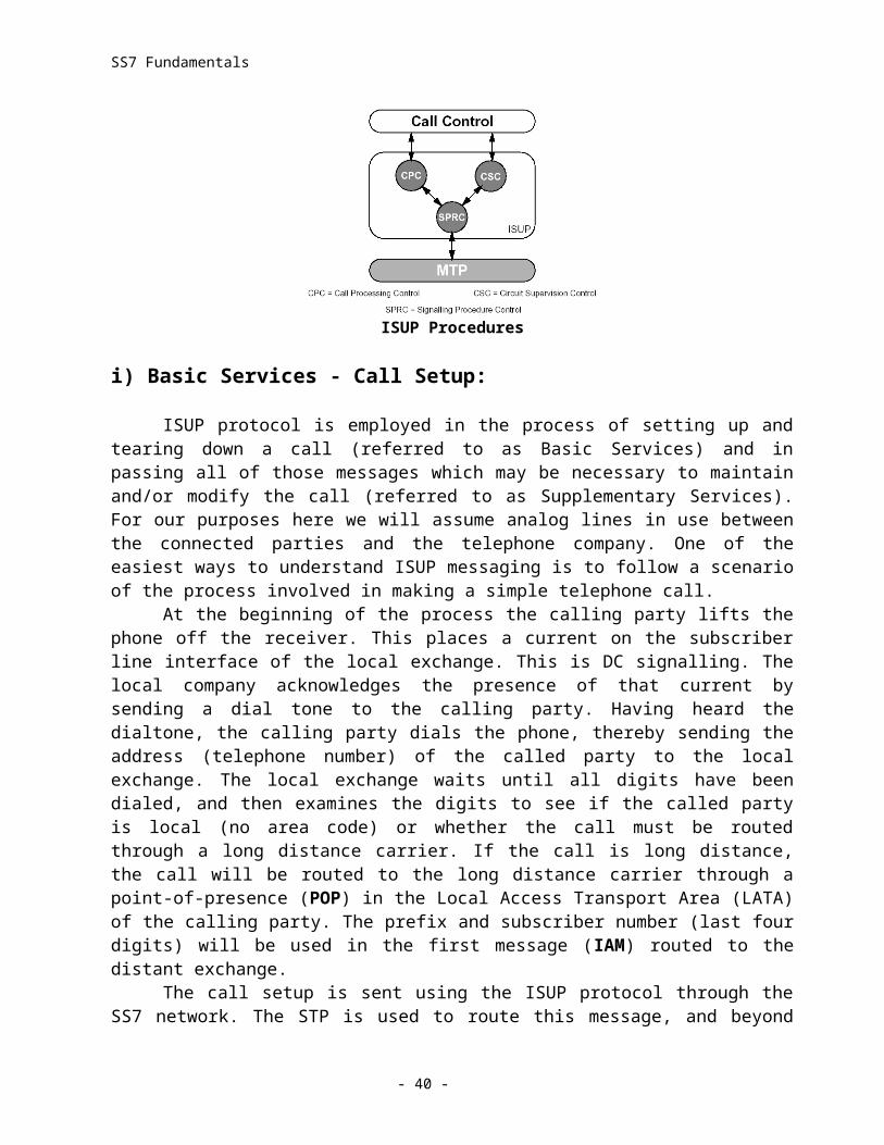
SS7 Fundamentals
drawing is to illustrate an ANSI routing label and a CCITT (ITU-TS) routing label. The one to be found in an MSU will depend, of course, on which standard is being employed by the node sending the message.For ANSI networks the routing label is identified as being the first 56 bits in the SIF (Signalling Information Field). ANSI provides for a network location to be identified by a 24 bit code. The first eight bits of this code is given the name of Network ID. Signalling Point Codes, in general, follow the general schema introduced by the telephone numbering scheme known as the North American Numbering Plan. In that plan, each succeeding value generally represents a smaller geographical area (area code, exchange) until the last number represents an individual phone line. For the SS7, the distinction is hierarchical rather than geographical. That is the network identifier identifies a network to which a point code belongs. This can be a code indicating a broad general network, or it can be a reserved code used to indicate that the identity is assigned to a group of commonly administered nodes which, together, do not qualify for full network status. With one of these reserved codes used as the network identifier, an indication is given that the next value (Network Cluster) will be used to identify the network to which the node belongs.
Thus the code can be used to identify smaller networks within a larger network and, finally, narrow down the addressing (Network Cluster Member) to address a single signalling point. The only reserved Network Cluster Member is the “empty” byte (eight zeros) which is used to identify an STP. The standards reserve this value for STP usage, but they don’t compel its use. What that means is that when you see a node with a Network Cluster Member value of zero, you know that the node is an STP. However, when you see a node with a Network Cluster Member code of other than zero, there is no guarantee that the node is not an STP.
The remaining field is the Signalling Link Selection Code. Different SCCP services require different handling of this code. SCCP services break down into four categories. These services are connectionless or connection oriented, each of which is further categorized as requiring or not requiring in-sequence delivery. The MTP level 3 normally rotates the SLS and each new code will direct the message to a new available link. When the SCCP requires it, the MTP stops rotating the code and each new message is directed to the same link, thereby guaranteeing in-sequence delivery. For the ANSI routing label, the only thing remaining to be identified is the field labeled “User Data.” This is the actual message. The letter “n” represents the total amount of data in the SIF. Since the routing label is always 56 bits (7 octets), “n-7” represents the size of the message (total octets in the field, less the routing label).
The differences in the CCITT (ITU-TS) routing label are relatively minor. The names of the signalling point code fields are changed (Zone instead of Network ID, Network instead of Network Cluster, and Signalling Point ID instead of Network Cluster Member). The ITU-TS standard also elected to allot a different number of bits to two of the three portions of the code (3-8-3 instead of 8-8-8). Fewer bits were also allotted to the SLS (4 instead of 5, and the ANSI 1996 standard supports 8 bits for the SLS). And, finally, the computation of the message size based on the total data in the SIF changes because only four octets need to be subtracted from the total data.
One remaining field in the MSU is the Check Bits field. This is an algorithm that allows the MTP to determine whether the number of bits transmitted is the same as the number of bits received. The last field is the trail flag. The trail flag is not used in the U.S. Therefore, in ANSI networks the MSU ends with the Check Bits.
- 40 -
SS7 Fundamentals
i-b) Link Status Signal Unit (LSSU):
As the name implies, the Link Status Signal Unit is used by the MTP to provide status information to the signalling points at either end of the link. These indications are placed in the one or two octet field called the Link Status field. Status indications relate to the current mode under which the MTP is monitoring the link. Recall that our earlier discussions about functionality mentioned two error rate monitors. The first was the AERM (Alignment Error Rate Monitor) employed during link alignment. At the beginning of the alignment process (while in the Out-of-alignment state) the MTP provides a status indication of “O.” When the alignment has proceeded to the proving period, the status of “N” (for Normal proving period) or the status of “E” (for Emergency proving period) is sent. By the way, as long as we are on the subject of Normal vs. Emergency alignment you may have wondered how the selection is made. The node itself does the selection, either as required by the application or by pre-configuration. The format of the Link Status Signal Unit is illustrated below.
LSSU Field Format
When a link is first powered up, and before the “O” status indication, the “OS” (Out-of-Service) status is sent. The same status is sent any time the link can neither receive nor send MSUs for any reason other than a Processor Outage. The sending of these status indications is somewhat of an interactive process on the part of the MTPs at either end of the link. For example, if the MTP at one end of the link has an “N” proving status it will send “N”. If the other end sends an “E” status, the side with the Normal status will not change that status. However, it will not cause a delay in the link realignment by performing the longer proving period. It will, instead, perform the shorter “E” proving period to be consistent with the realignment being performed by the other side. Even as it does so, it still sends “N”.
While the MTP is monitoring normal transmission (using the SUERM or Signal Unit Error Rate Monitor) it will send a status of “B” (link Busy). That same MTP stops sending either positive or negative acknowledgments. The MTP at the other end of the link sets a long timer to await the clearance of the congestion. It also resets the “excessive delay of acknowledgment” timer every time it receives (periodically during the congestion period) a new indication of “B.” A status of “PO” is sent when the MTP detects a problem in delivering messages to levels 3 or 4. The same MTP then begins message discard. When the opposite MTP receives “PO”, it informs level 3 and places Fill In Signal Units on the link.
i-c) Fill In Signal Unit (FISU):
If you pull a link out of the link port, the MTP will detect a “failed link.” This is due to the fact that the MTP continues to monitor Signal Units and now has no data with which to deal.
- 41 -
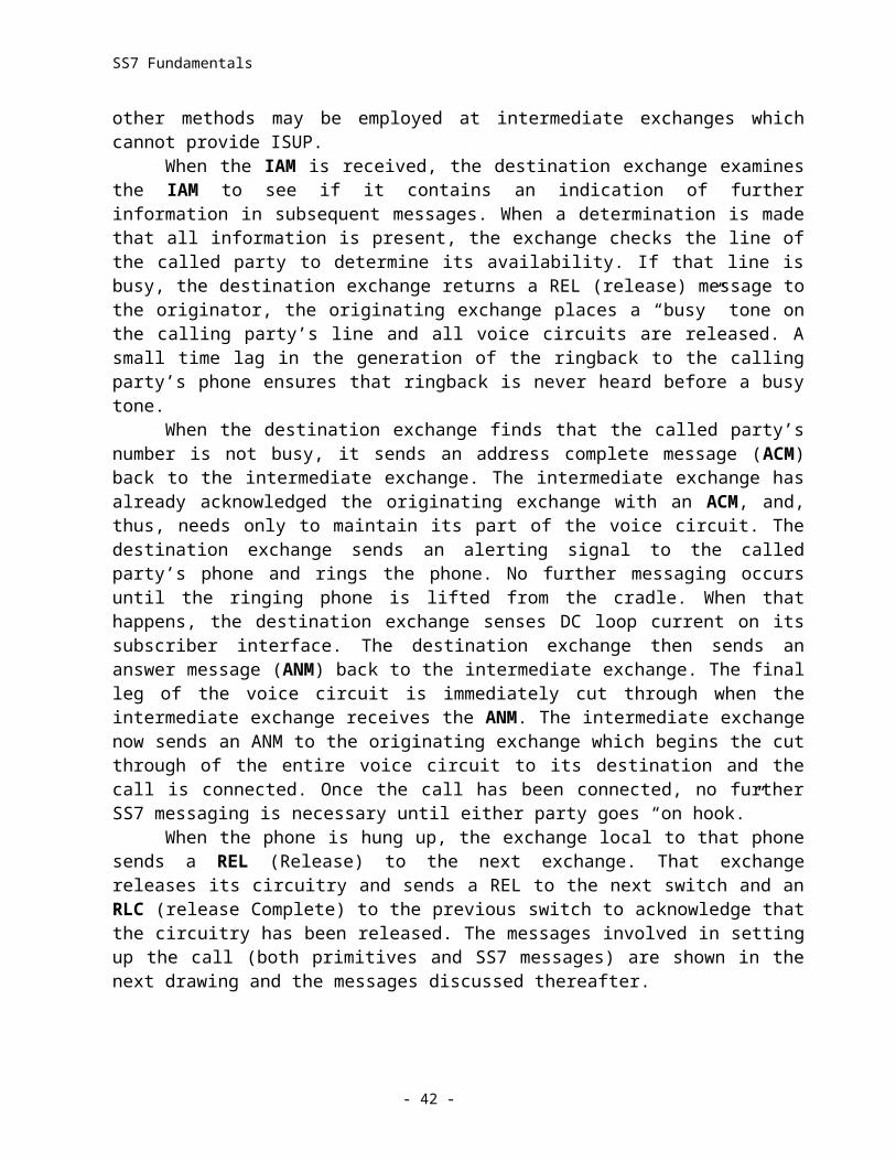
SS7 Fundamentals
While nodes are communicating, there are many times when no messages are being sent. If there were no data to read, the MTP would have to conclude that it had detected a “failed link”. For this reason, the MTP cannot allow any time period in which the link carries no data. The transmitting MTP fills all such blanks with Fill In Signal Units. The format of the Fill In Signal Unit is illustrated below.
FISU Field Format
The MTP can continue to monitor for valid flags, octet integrity and package size. It simply finds no data to send to level 3. On the transmitting side, no changes are made. The FSN applied to the last message simply reappears in each FISU until a new message is sent. There is another time when the FISU becomes handy. During the alignment procedure the MTP uses the AERM to monitor the link. Until the link is placed in an In Service state, there are no messages being sent. Therefore, the MTP puts FISUs on the link and monitors them during the proving period.
ACRONYMS
ACD Automatic Call DistributorACG Automatic Code GappingACM Address Complete MessageAFR Automatic Flexible RoutingAHT Average Handle TimeAIN Advanced Intelligent NetworkAIOD Automatic Identified Outward CallingAMA Automatic Message AccountingAMATPS AMA Teleprocessing SystemAMP AIN Maintenance ParameterANI Automatic Number IdentificationANM Answer MessageANSI American National Standards InstituteAPI Application Programming InterfaceARP Address Resolution ProtocolASA Average Speed of AnswerASN.1 Abstract Syntax Notation 1ASE Application Service ElementATB All Trunks BusyATP Acceptance Test ProcedureAUI Attachment Unit Interface
- 42 -
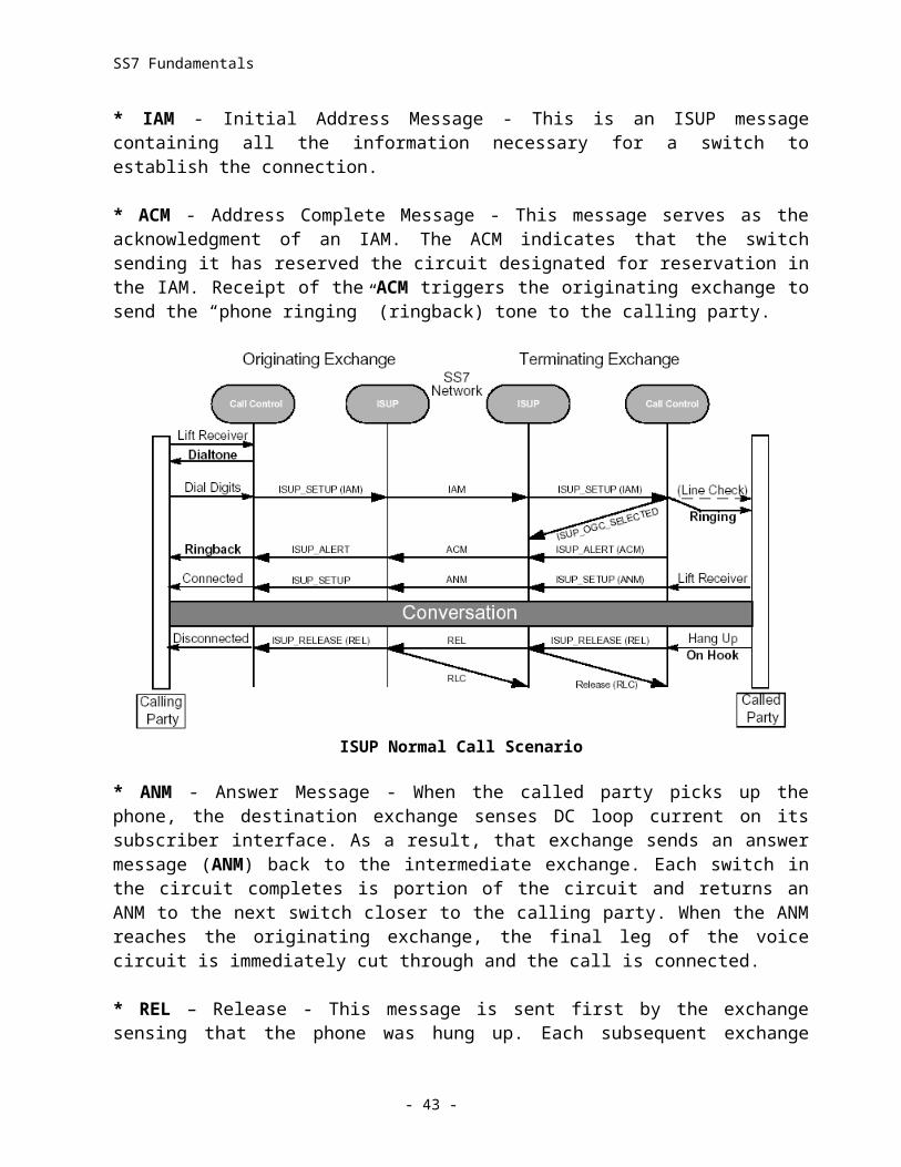
SS7 Fundamentals
AW Admin WorkstationBAF Bellcore AMA FormatBBG Basic Business GroupBCC Bellcore Client CompanyBCD Binary Coded DecimalBCI Backward Call IndicatorsBCLID Bulk Calling Line IdentificationBCM Basic Call ModelBER Basic Encoding RulesBG Business GroupBGID Business Group IdentificationBRI Basic Rate InterfaceBSN Backward Sequence NumberCAC Carrier Access CodeCAP Competitive Access ProviderCC Call ControlCCA Call Control AdjunctCCITT Consultative Committee on International Telephone & TelegraphCCS Common Channel SignallingCDAR Customer Dialed Account RecordingCDP Customized Dialing PlanCDPD Cellular Digit al Packet DataCED Call Entered DigitsCGB Circuit Group Blocking MessageCGU Circuit Group Unblocking MessageCIC Carrier Identification CodeCIDS Calling Identity Delivery & SuppressionCLID Calling Line IDCLLI Common Language Location IdentificationCMC Cellular Mobile CarrierCMS (AT&T’S) Call Management SystemCNAB Call Name Delivery BlockingCO Central OfficeCOT Continuity Test MessageCPC Call Processing ControlCPE Customer Premises EquipmentCPG Call Progress MessageCR Conditional RequirementCRA Circuit Reservation Acknowledgment MessageCRM Circuit Reservation MessageCS-1 Capability Set 1CSC Circuit Supervision ControlCSU Channel Service UnitCT Call TypeCVR Circuit Validation Response MessageCVT Circuit Validation Test Message
- 43 -
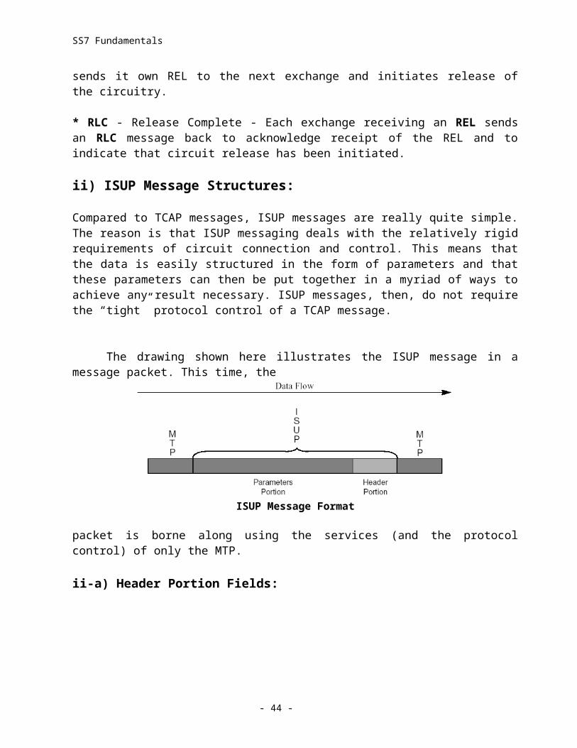
SS7 Fundamentals
DACS Digital Access Cross-Connect SystemDCE Data Circuit EquipmentDMP Device Management ProtocolDN Dialed NumberDNIS Dialed Number Identification ServiceDP Dial PulseDPC Destination Point CodeDSVD Digital Simultaneous Voice and DataDTE Data Terminal EquipmentDTMF Dial Tone MultifrequencyDUP Data User PartDXI Data Exchange InterfaceEA Equal AccessEADAS Engineering & Administration Data Acquisition SystemEADASNM EADAS Network AdministrationEAEO Equal Access End OfficeEAMF Equal Access MultifrequencyEBCDIC Extended Binary Coded Decimal Interchange CodeEDP Event Detection PointEIA Electronic Industries AssociationEIR Equipment Identification RegisterEKTS Electronic Key Telephone ServiceEMS Event Management ServiceEO End OfficeESN Electronic Serial NumberEXM Exit MessageFCS Frame Check SequenceFISU Fill-in Signal UnitFRAD Frame Relay Access DeviceFRL Facility Restriction LevelFUNI Frame User Network InterfaceFSD Feature Specific DocumentFSN Forward Sequence NumberFSS Facility Selective ServiceFTE Full Time EquivalentFTP File Transfer ProtocolFX Foreign ExchangeGN Generic NameGRS Group Reset MessageGSC Gateway Switching CenterGSM Group Special MobileGTT Global Title TranslationsGTV Global Title ValueGUI Graphical User InterfaceHDLC High Level Data Link ControlHFC Hybrid Fiber Coaxial Cable
- 44 -
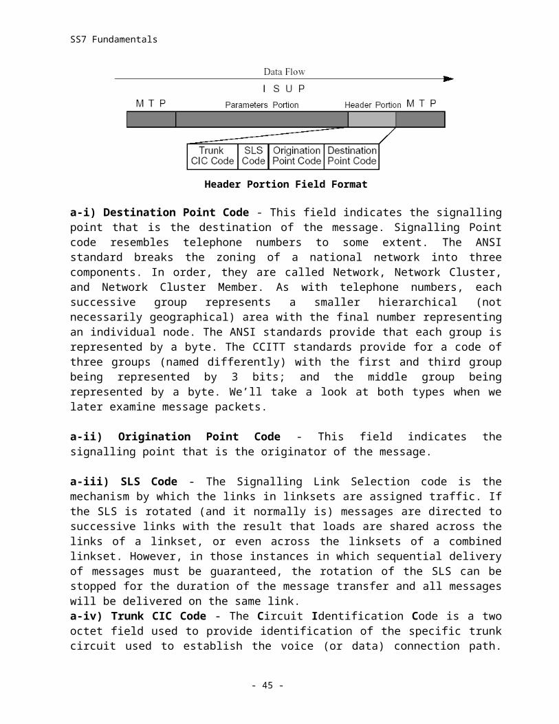
SS7 Fundamentals
HLR Home Location RegisterIAM Initial Address MessageIC Interexchange CarrierICP Intelligent Call ProcessingICR Intelligent Call RouterIDLC Integrated Digital Loop CarrierISP Intermediate Service PartIDT Integrated Digital TerminalINR Information Request MessageIP Intelligent Peripheral or Internet ProtocolIPC Interprocess CommunicationIPI Intelligent Peripheral InterfaceISP Intermediate Service PartISPC International Signalling Point CodeISDN Integrated Services Digital Network (Used with CPE)ISDNUP ISDN User PartISUP ISDN User Part (Used with Circuit Oriented)IWX Interworking FunctionIXC Interexchange CarrierLAA Longest Available AgentLAN Local Area NetworkLATA Local Access & Transport AreaLI Length IndicatorLSSU Link Status Signal UnitLSSGR LATA Switching & Signalling Generic RequirementsLOCREQ Location RequestMAP Mobility Application PartMBG Multi-switch Business GroupMCC Mobile Country CodeMIN Mobile Identification NumberMGW Mini-Gateway PrototypeMLHG Multi-line Hunt GroupMMI Man-Machine InterfaceMSC Mobile Switching CenterMSISDN Mobile Station ISDN NumberMSU Message Signal UnitMUX MultiplexerMTP Message Transfer PartNAA Next Available AgentNCA Non-Call AssociatedNCP Network Control PointNDC National Destination CodeNIC Network Interface ControllerNNI Network Node InterfaceNPA Numbering Plan AreaNSP Network Services Part
- 45 -
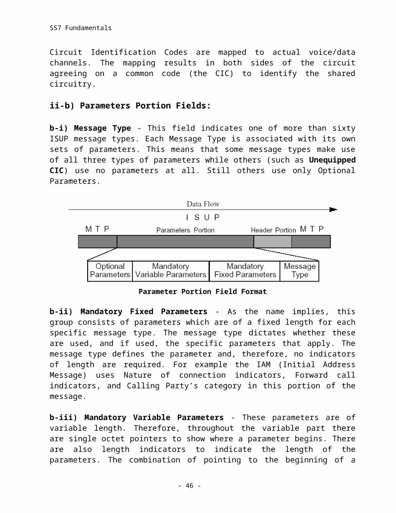
SS7 Fundamentals
ODBC Open Database ConnectivityOE Office EquipmentOMAP Operations & Maintenance Application PartOPC Origination Point CodeOPI Open Peripheral InterfaceOS Operations SystemOSI Open Systems InterfaceOTGR Operations Technology Generic RequirementPBX Private Branch ExchangePCS Personal Communications ServicesPG Peripheral GatewayPIC Point In CallPIM Peripheral Interface ManagerPPP Point-to-Point ProtocolPRI Primary Rate InterfacePROFREQ Profile RequestPSN Alternative to PSTN (Public Switched Telephone Network)PSTN Public Switched Telephone NetworkREGNOT Registration NotificationRISC Reduced Instruction Set ComputingROUTREQ Routing RequestSANC Signalling Area Network CodeSCCP Signalling Connection Control PartSCP Service Control PointSDLC Synchronous Data Link ControlSEP Signalling EndpointSF Status FieldSI Service IndicatorSIF Signalling Information FieldSIO Signalling Information OctetSLC Signalling Link CodeSLIP Serial Line Internet ProtocolSLS Signalling Link SelectionSLP Service Logic ProgramSMDS Switched Multimegabit Digital ServiceSMS Service Management SystemSN Services NodeSNA Systems Network ArchitectureSNM Signalling Network ManagementSNMP Simple Network Management ProtocolSNT Signalling Network TestingSP Signalling PointSPC Signalling Point CodeSPID Service Provider IdentifierSPM Signalling Point ManagerSQL Structured Query Language
- 46 -

SS7 Fundamentals
SPR Signalling Point w/SCCP RelaySPRC Signalling Procedure ControlSRTC Sub Rate ChannelSS7 Signalling System 7SSF Sub-Service FieldSSN Sub System NumberSSP Service Switching PointSTP Signalling Transfer PointSU Signal UnitsTA Technical AdvisoryTC Transaction CapabilitiesTCAP Transaction Capabilities Application PartTCM Traveling Class MarkTCP/IP Transmission Control Protocol/Internet ProtocolTDM Time Division MultiplexerTDP Trigger Detection PointTLDN Temporary Local Directory NumberTR Technical ReferenceTUP Telephone Users PartUDP User Datagram ProtocolUDT UnitdataUDTS Unitdata ServiceVAD Voice Activated DialingVANC Voice Activated Network ControlVLR Visitor Location RegisterVPN Virtual Private NetworkVRU Voice Response UnitWAN Wide Area NetworkWATS Wide Area Telephone ServiceXUDT Extended UnitdataXUDTS Extended Unitdata Service
- 47 -