Embed Size (px)
Citation preview
Purll 1 20th Annual AIAA/USU Conference on Small Satellites
1 INTRODUCTION
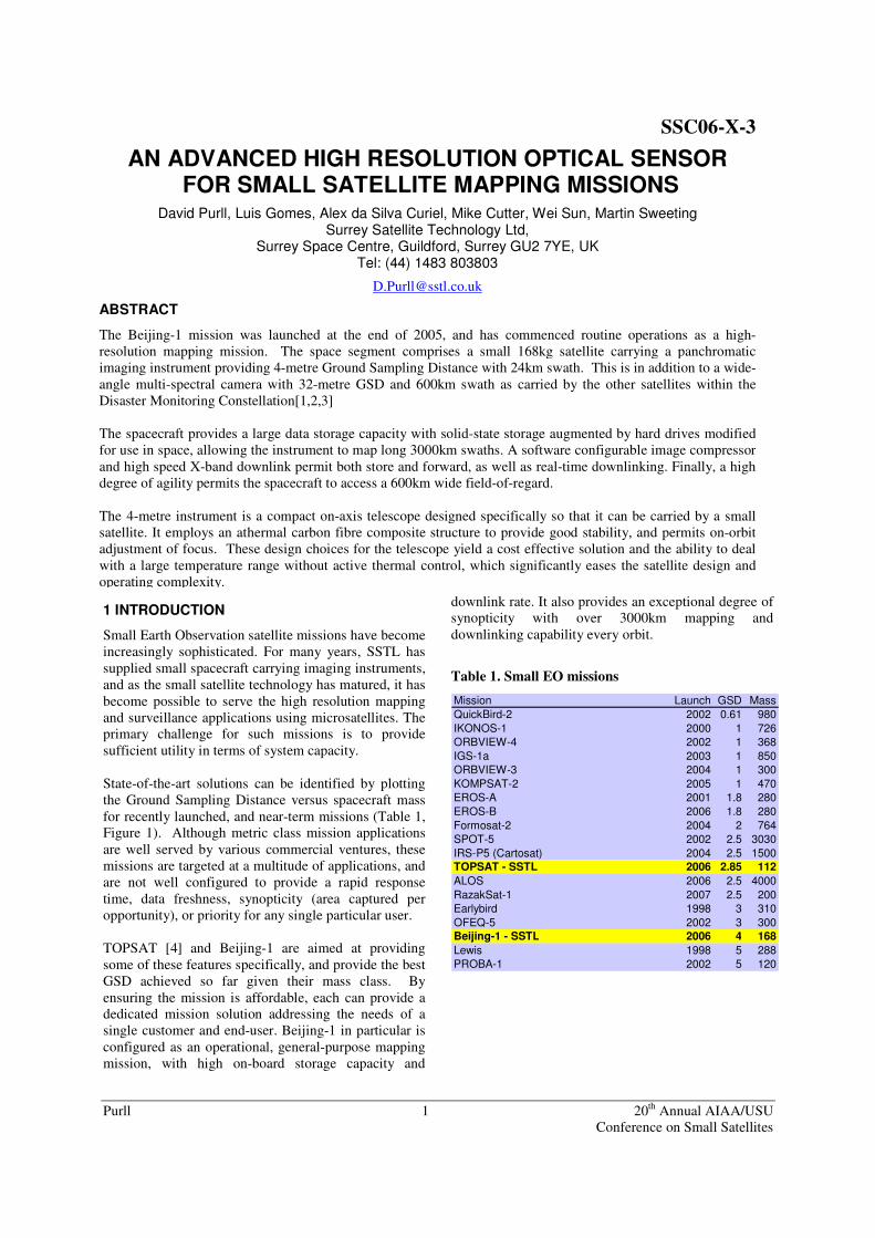
Small Earth Observation satellite missions have become increasingly sophisticated. For many years, SSTL has supplied small spacecraft carrying imaging instruments, and as the small satellite technology has matured, it has become possible to serve the high resolution mapping and surveillance applications using microsatellites. The primary challenge for such missions is to provide sufficient utility in terms of system capacity. State-of-the-art solutions can be identified by plotting the Ground Sampling Distance versus spacecraft mass for recently launched, and near-term missions (Table 1, Figure 1). Although metric class mission applications are well served by various commercial ventures, these missions are targeted at a multitude of applications, and are not well configured to provide a rapid response time, data freshness, synopticity (area captured per opportunity), or priority for any single particular user. TOPSAT [4] and Beijing-1 are aimed at providing some of these features specifically, and provide the best GSD achieved so far given their mass class. By ensuring the mission is affordable, each can provide a dedicated mission solution addressing the needs of a single customer and end-user. Beijing-1 in particular is configured as an operational, general-purpose mapping mission, with high on-board storage capacity and
downlink rate. It also provides an exceptional degree of synopticity with over 3000km mapping and downlinking capability every orbit.
Table 1. Small EO missions
Mission Launch GSD MassQuickBird-2 2002 0.61 980IKONOS-1 2000 1 726ORBVIEW-4 2002 1 368IGS-1a 2003 1 850ORBVIEW-3 2004 1 300KOMPSAT-2 2005 1 470EROS-A 2001 1.8 280EROS-B 2006 1.8 280Formosat-2 2004 2 764SPOT-5 2002 2.5 3030IRS-P5 (Cartosat) 2004 2.5 1500TOPSAT - SSTL 2006 2.85 112ALOS 2006 2.5 4000RazakSat-1 2007 2.5 200Earlybird 1998 3 310OFEQ-5 2002 3 300Beijing-1 - SSTL 2006 4 168Lewis 1998 5 288PROBA-1 2002 5 120
SSC06-X-3
AN ADVANCED HIGH RESOLUTION OPTICAL SENSOR FOR SMALL SATELLITE MAPPING MISSIONS
David Purll, Luis Gomes, Alex da Silva Curiel, Mike Cutter, Wei Sun, Martin Sweeting Surrey Satellite Technology Ltd,
Surrey Space Centre, Guildford, Surrey GU2 7YE, UK Tel: (44) 1483 803803
ABSTRACT
The Beijing-1 mission was launched at the end of 2005, and has commenced routine operations as a high-resolution mapping mission. The space segment comprises a small 168kg satellite carrying a panchromatic imaging instrument providing 4-metre Ground Sampling Distance with 24km swath. This is in addition to a wide-angle multi-spectral camera with 32-metre GSD and 600km swath as carried by the other satellites within the Disaster Monitoring Constellation[1,2,3] The spacecraft provides a large data storage capacity with solid-state storage augmented by hard drives modified for use in space, allowing the instrument to map long 3000km swaths. A software configurable image compressor and high speed X-band downlink permit both store and forward, as well as real-time downlinking. Finally, a high degree of agility permits the spacecraft to access a 600km wide field-of-regard. The 4-metre instrument is a compact on-axis telescope designed specifically so that it can be carried by a small satellite. It employs an athermal carbon fibre composite structure to provide good stability, and permits on-orbit adjustment of focus. These design choices for the telescope yield a cost effective solution and the ability to deal with a large temperature range without active thermal control, which significantly eases the satellite design and operating complexity.
Purll 2 20th Annual AIAA/USU Conference on Small Satellites
High resolution EO missionGSD achieved for a spacecraft mass
0
1
2
3
4
5
6
0 500 1000 1500
Mass (kg)
GS
D (m
)
TOPSAT
Beijing-1
Figure 1. GSD vs spacecraft mass
2 MISSION OVERVIEW
The Beijing-1 Satellite (also known as China DMC+4) was designed and manufactured by Surrey Satellite Technology Limited (SSTL) of Guildford, United Kingdom, for the private company “Beijing LandView Mapping Information Technology Co”. (BLMIT), of Beijing, China, as the space segment of the Beijing-1 Project. The project comprised also the installation in Beijing of a Mission Control Centre, consisting of an S-band ground station and associated control systems, and the support to the customer payload data X-band ground station. Designed from the beginning as a pure mapping mission, the project aims at providing the Chinese market with yearly high resolution mapping of the Chinese territory. Special attention is being given to the large amount of building work being done for the Olympic Games in Beijing, since the mission allows re-mapping of the urban area every 3-4 days, at 4 meter ground sampling distance (GSD), a useful capacity in rapidly changing urban environments. The satellite was designed to map the entire Chinese territory every six month, at 4 meter resolution in Pan-chromatic mode. The Beijing-1 Satellite is a “DMC+4” platform, with all the capabilities of the Disaster Monitoring Constellation (DMC) platform, plus a high performance 4-meter GSD imager, and an associated payload data processing, storage and transmission chain. Associated to an agile attitude system, that allows 30º off track roll manoeuvres, and to an X-band 40Mbit/sec downlink capability, these make the platform a very powerful Earth observation tool, at a relatively very low cost. The DMC side of the platform uses the three band, 32-meter GSD imager (MSI) used on the standard DMC spacecraft, but with the added capabilities available on
a DMC+ platform. Although these capabilities can be tailored, for the Beijing-1 mission, these include on-board hardware data compression, using a fully re-programmable high capability DSP unit, 4Gbytes of volatile mass data storage, 240Gbytes of non-volatile mass data storage (fully re-writable on demand), data encryption and the already mentioned downlink, providing data transfer rates at 8 (in S-band), 20 and 40 Mbit/sec (X-band). The 4-meter GSD imager was developed by the space division of the SIRA1 group, , and is a light weight mapping telescope with in-orbit focusing capability. The DMC+4 platform is highly configurable. Allowing the operation if several different modes, each optimised for a specific objective. These modes are re-configurable from the ground, and new ones can be tailored as required by the operators. The main modes defined for Beijing-1 are listed in Table 2.
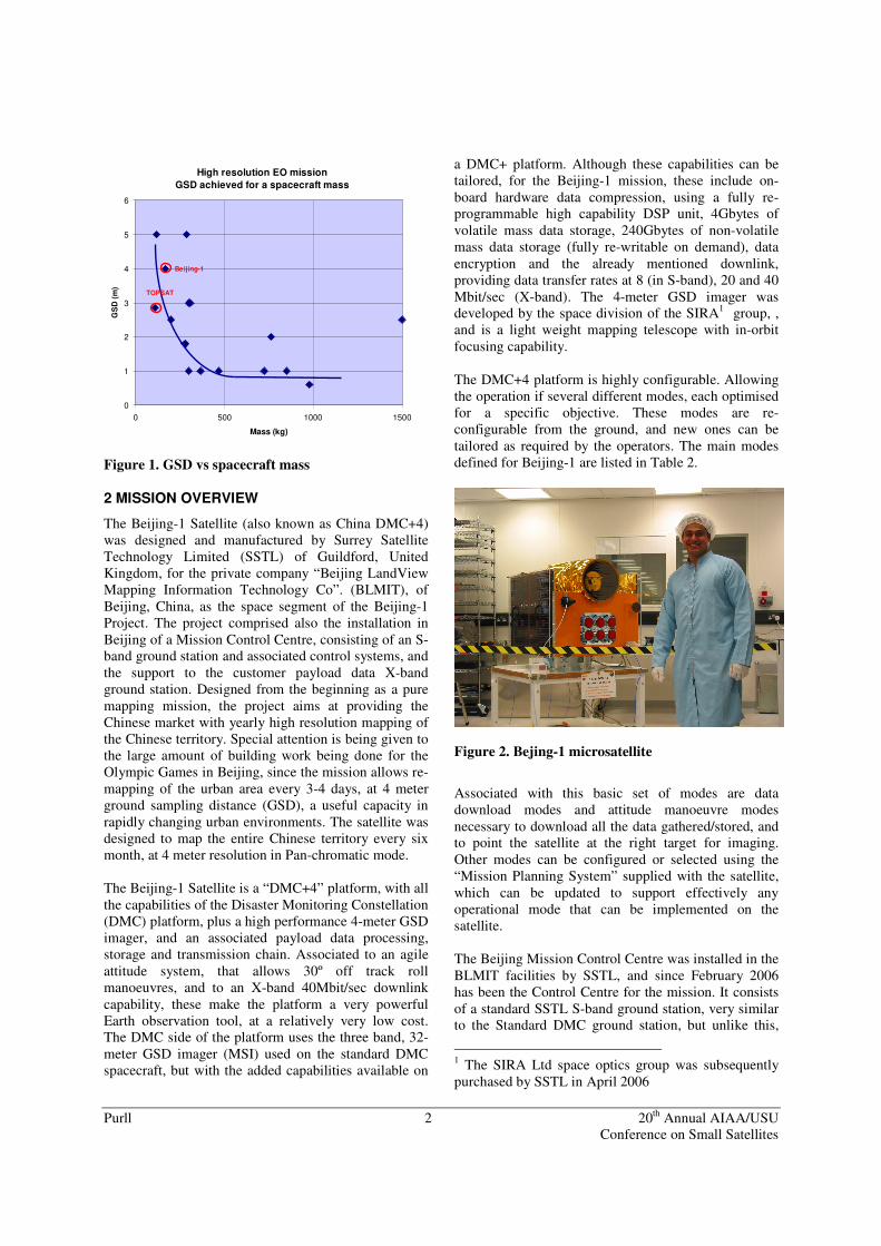
Figure 2. Bejing-1 microsatellite
Associated with this basic set of modes are data download modes and attitude manoeuvre modes necessary to download all the data gathered/stored, and to point the satellite at the right target for imaging. Other modes can be configured or selected using the “Mission Planning System” supplied with the satellite, which can be updated to support effectively any operational mode that can be implemented on the satellite. The Beijing Mission Control Centre was installed in the BLMIT facilities by SSTL, and since February 2006 has been the Control Centre for the mission. It consists of a standard SSTL S-band ground station, very similar to the Standard DMC ground station, but unlike this,
1 The SIRA Ltd space optics group was subsequently purchased by SSTL in April 2006
Purll 3 20th Annual AIAA/USU Conference on Small Satellites
uses a customer furnished antenna. The S-band ground station is integrated with the customer X-band data receiving ground station. Beijing-1 was launched on the 27th October 2005, from the Plesetsk Cosmodrome in northern Russia, aboard a Cosmos launcher. Signal was acquired on the first pass over SSTL’s ground station, and attitude stabilisation started immediately. Commissioning included the focusing of the 4-meter imager, the calibration of the attitude control system, and a demonstration of the absolute pointing accuracy on the ground within 650m (1-sigma) of the target (across track). After completion of commissioning, all mission modes were explored, in order to refine the operational concepts for each mode, leading up to a handover to the customer in March 2006. The system is currently being used by BLMIT under nominal operations.
3 INSTRUMENT
IMAGER DESIGN PRINCIPLES
The principal raison d’être of small satellites is in changing the economics of space. To produce the most cost-effective solution to a mission it is imperative not only that the components can be built cheaply but also that the satellite can be integrated quickly and that the platform solutions can be reused so that they maintain a high degree of design heritage. Rather than developing a custom imaging mission solution, the design philosophy adopted was to develop a generic and scalable imaging instrument, to fit on a scalable spacecraft platform. This then would allow the platform and instrument to be configured for variants of this mission when required.
The payload design team took it as their mantra that the payload should impose as few special conditions on the satellite as possible. This meant that the imager must cope with a high degree of thermal variation and vibration without requiring special actions by the satellite manufacturer to radically change the platform design. It has become fashionable to use the three-mirror anastigmat (TMA) optical design form, as was done for payloads used on two recent SSTL missions. Although applicable in some circumstances, there are well-known downsides of difficult alignment and high stability requirements. A high degree of thermal control typically has to be demanded for the payload, a problem a small satellite manufacturer could well do without. In at least one project, the time schedule was strongly
delayed by the TMA manufacturing and testing difficulties and the vibration specification was reduced compared with the one given to our imager team. In contrast, the imager presented in this paper (Figure 3) uses a more conventional design form and relies on good engineering practice to live within the constraints of a cost-effective small satellite mission.
Table 2. Beijing-1 Mission Modes
Mode Type S/C Configuration Applications Pan Real time imaging
Pan image being captured, compressed and downloaded in real time. MSI image might be stored at the same time if desired
• Local mapping • Localised real time security
assessment • Support for local emergencies
Pan image store Pan image captured and stored in mass storage device (selectable volatile or non-volatile)
• Mapping • “Detailed look” imaging
MS window pseudo real time imaging
MSI image capture in windowing mode, with download in pseudo-real time. Pan image can be captured at same time and stored in mass storage device
• Disaster monitoring • General medium and high
resolution mapping • Sharpening of medium resolution
images MSI strip real time imaging
MSI strip image capture, with download in real time. Pan image can be captured at same time and stored in mass storage device
• Disaster monitoring • General medium and high
resolution mapping MSI image store MSI image captured and stored in mass storage
device (selectable volatile or non-volatile) • Mapping
Purll 4 20th Annual AIAA/USU Conference on Small Satellites
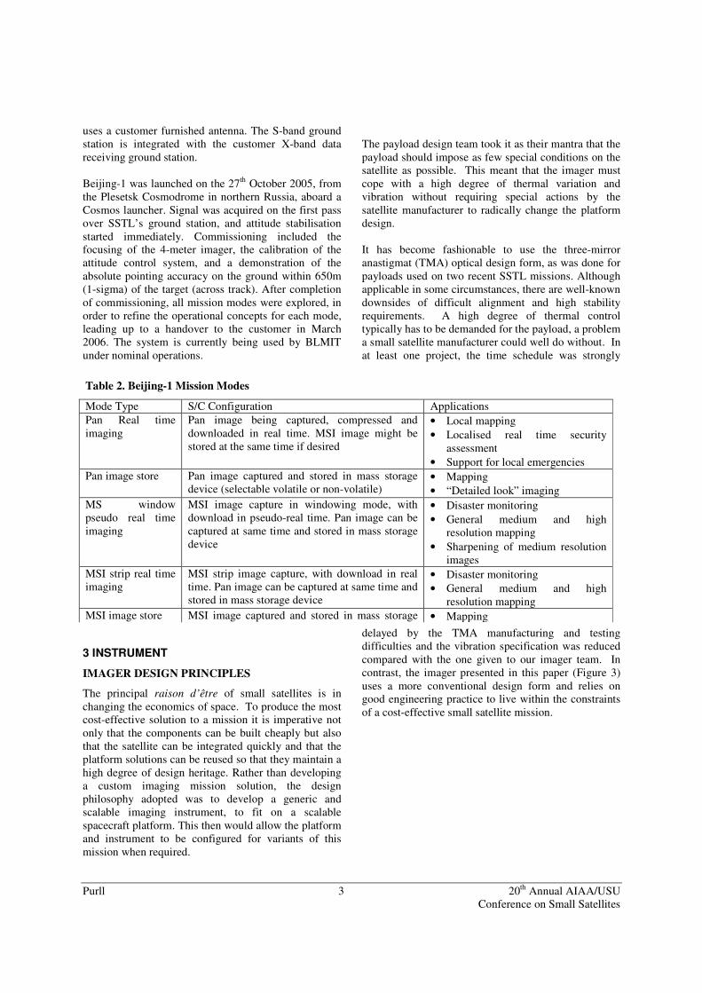
Figure 3 The Beijing-1 Mapping Telescope
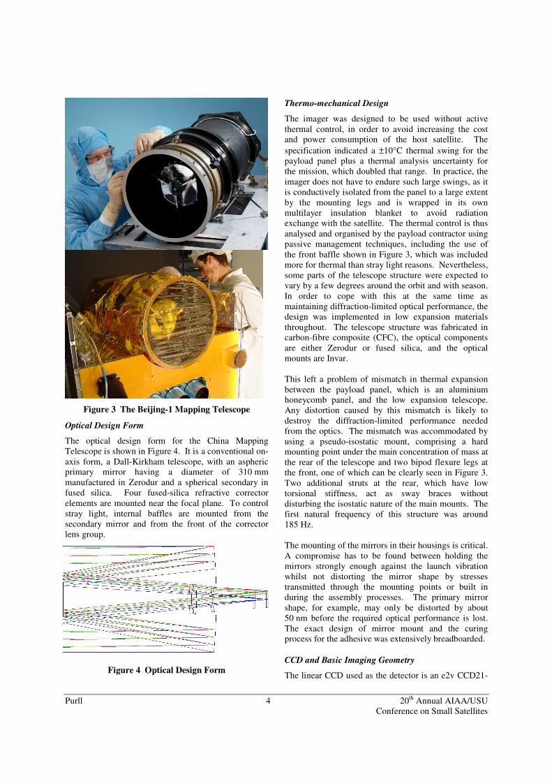
Optical Design Form
The optical design form for the China Mapping Telescope is shown in Figure 4. It is a conventional on-axis form, a Dall-Kirkham telescope, with an aspheric primary mirror having a diameter of 310 mm manufactured in Zerodur and a spherical secondary in fused silica. Four fused-silica refractive corrector elements are mounted near the focal plane. To control stray light, internal baffles are mounted from the secondary mirror and from the front of the corrector lens group.
Figure 4 Optical Design Form
Thermo-mechanical Design
The imager was designed to be used without active thermal control, in order to avoid increasing the cost and power consumption of the host satellite. The specification indicated a ±10°C thermal swing for the payload panel plus a thermal analysis uncertainty for the mission, which doubled that range. In practice, the imager does not have to endure such large swings, as it is conductively isolated from the panel to a large extent by the mounting legs and is wrapped in its own multilayer insulation blanket to avoid radiation exchange with the satellite. The thermal control is thus analysed and organised by the payload contractor using passive management techniques, including the use of the front baffle shown in Figure 3, which was included more for thermal than stray light reasons. Nevertheless, some parts of the telescope structure were expected to vary by a few degrees around the orbit and with season. In order to cope with this at the same time as maintaining diffraction-limited optical performance, the design was implemented in low expansion materials throughout. The telescope structure was fabricated in carbon-fibre composite (CFC), the optical components are either Zerodur or fused silica, and the optical mounts are Invar. This left a problem of mismatch in thermal expansion between the payload panel, which is an aluminium honeycomb panel, and the low expansion telescope. Any distortion caused by this mismatch is likely to destroy the diffraction-limited performance needed from the optics. The mismatch was accommodated by using a pseudo-isostatic mount, comprising a hard mounting point under the main concentration of mass at the rear of the telescope and two bipod flexure legs at the front, one of which can be clearly seen in Figure 3. Two additional struts at the rear, which have low torsional stiffness, act as sway braces without disturbing the isostatic nature of the main mounts. The first natural frequency of this structure was around 185 Hz. The mounting of the mirrors in their housings is critical. A compromise has to be found between holding the mirrors strongly enough against the launch vibration whilst not distorting the mirror shape by stresses transmitted through the mounting points or built in during the assembly processes. The primary mirror shape, for example, may only be distorted by about 50 nm before the required optical performance is lost. The exact design of mirror mount and the curing process for the adhesive was extensively breadboarded. CCD and Basic Imaging Geometry
The linear CCD used as the detector is an e2v CCD21-
Purll 5 20th Annual AIAA/USU Conference on Small Satellites
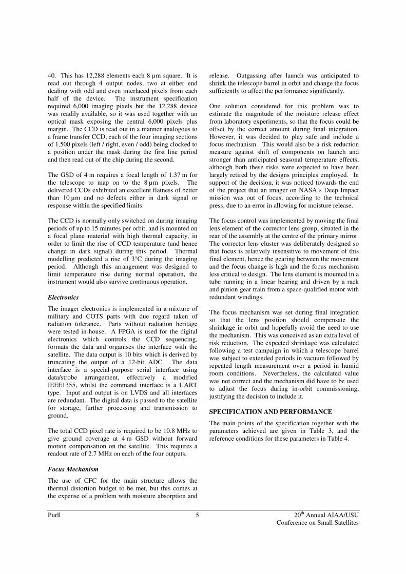
40. This has 12,288 elements each 8 µm square. It is read out through 4 output nodes, two at either end dealing with odd and even interlaced pixels from each half of the device. The instrument specification required 6,000 imaging pixels but the 12,288 device was readily available, so it was used together with an optical mask exposing the central 6,000 pixels plus margin. The CCD is read out in a manner analogous to a frame transfer CCD, each of the four imaging sections of 1,500 pixels (left / right, even / odd) being clocked to a position under the mask during the first line period and then read out of the chip during the second. The GSD of 4 m requires a focal length of 1.37 m for the telescope to map on to the 8 µm pixels. The delivered CCDs exhibited an excellent flatness of better than 10 µm and no defects either in dark signal or response within the specified limits. The CCD is normally only switched on during imaging periods of up to 15 minutes per orbit, and is mounted on a focal plane material with high thermal capacity, in order to limit the rise of CCD temperature (and hence change in dark signal) during this period. Thermal modelling predicted a rise of 3°C during the imaging period. Although this arrangement was designed to limit temperature rise during normal operation, the instrument would also survive continuous operation. Electronics
The imager electronics is implemented in a mixture of military and COTS parts with due regard taken of radiation tolerance. Parts without radiation heritage were tested in-house. A FPGA is used for the digital electronics which controls the CCD sequencing, formats the data and organises the interface with the satellite. The data output is 10 bits which is derived by truncating the output of a 12-bit ADC. The data interface is a special-purpose serial interface using data/strobe arrangement, effectively a modified IEEE1355, whilst the command interface is a UART type. Input and output is on LVDS and all interfaces are redundant. The digital data is passed to the satellite for storage, further processing and transmission to ground. The total CCD pixel rate is required to be 10.8 MHz to give ground coverage at 4 m GSD without forward motion compensation on the satellite. This requires a readout rate of 2.7 MHz on each of the four outputs. Focus Mechanism
The use of CFC for the main structure allows the thermal distortion budget to be met, but this comes at the expense of a problem with moisture absorption and
release. Outgassing after launch was anticipated to shrink the telescope barrel in orbit and change the focus sufficiently to affect the performance significantly. One solution considered for this problem was to estimate the magnitude of the moisture release effect from laboratory experiments, so that the focus could be offset by the correct amount during final integration. However, it was decided to play safe and include a focus mechanism. This would also be a risk reduction measure against shift of components on launch and stronger than anticipated seasonal temperature effects, although both these risks were expected to have been largely retired by the designs principles employed. In support of the decision, it was noticed towards the end of the project that an imager on NASA’s Deep Impact mission was out of focus, according to the technical press, due to an error in allowing for moisture release. The focus control was implemented by moving the final lens element of the corrector lens group, situated in the rear of the assembly at the centre of the primary mirror. The corrector lens cluster was deliberately designed so that focus is relatively insensitive to movement of this final element, hence the gearing between the movement and the focus change is high and the focus mechanism less critical to design. The lens element is mounted in a tube running in a linear bearing and driven by a rack and pinion gear train from a space-qualified motor with redundant windings. The focus mechanism was set during final integration so that the lens position should compensate the shrinkage in orbit and hopefully avoid the need to use the mechanism. This was conceived as an extra level of risk reduction. The expected shrinkage was calculated following a test campaign in which a telescope barrel was subject to extended periods in vacuum followed by repeated length measurement over a period in humid room conditions. Nevertheless, the calculated value was not correct and the mechanism did have to be used to adjust the focus during in-orbit commissioning, justifying the decision to include it. SPECIFICATION AND PERFORMANCE
The main points of the specification together with the parameters achieved are given in Table 3, and the reference conditions for these parameters in Table 4.

Purll 6 20th Annual AIAA/USU Conference on Small Satellites
Table 3 Main Points of the Specification
Parameter Required Achieved GSD (m) 4 4 Swath (km) 24 24 Band (nm) 500 - 800 500 - 800 Band edge accuracy across FoV (nm) ±30 2
Energy in pass-band ≥ 90% 98% MTF at Nyquist: centre
edge ≥ 15% ≥ 10%
≥ 19.6% ≥ 13.6%
Signal-to-noise ratio ≥ 140 210 Mass (kg) ≤ 25 24 Power (W) at 28V ≤ 12 11.9 Volume (mm3) except mounting feet 790x400x400 790x380x378
Table 4 Reference Conditions
Parameter Conditions Orbit 686 km, sun synchronous,
11:00 LTAN, nadir pointing Signal 0.3 albedo at 35° latitude
at 11:00 on March 21st Temperatures:
Performance Operational
Survival
at imager mounting panel: 10°C ± 10° ± 10° uncertainty -25°C to +60°C -50°C to +88°C
Vibration (qual) 21 grms random vibration 1 g2/Hz peak
Typical test results for the most important property of the imager, the MTF, are given in Figure 5 for the maximum field angle. The Nyquist limit is at 62.5 cycles/mm. These are end-to-end results including the optical system, detector and electronics, and were measured on the flight imager after environmental testing. The effect of satellite motion on the along-track results is not yet included.
MTF, cross-track, 1° field
0
0.2
0.4
0.6
0.8
1
0 10 20 30 40 50 60Cycles/mm
MT
F
MTF, along-track, 1° field
0
0.2
0.4
0.6
0.8
1
0 10 20 30 40 50 60Cycles/mm
MTF
Figure 5 Typical MTF Curves
The measured spectral response of the imager is given in Figure 6. The band edge cut-offs were achieved by a dielectric coating on the secondary mirror in combination with a glass blocking filter for the blue end.
0.0E+00
2.0E+04
4.0E+04
6.0E+04
8.0E+04
1.0E+05
1.2E+05
1.4E+05
1.6E+05
1.8E+05
450 500 550 600 650 700 750 800 850Wavelength, nm
Rep
sons
e, A
DU
/ W
.cm
^-2.
sr^-
1
Figure 6 Measured Spectral Response
FUTURE DEVELOPMENTS
Based on the heritage of the 4 m imager, design and development is currently progressing for a family of five-band multi-spectral imagers with 2 to 2.5 m GSD in the panchromatic channel and 4 to 5 m GSD in the spectral channels. They will have swath widths of 16 to
Purll 7 20th Annual AIAA/USU Conference on Small Satellites
20 km. The spectral bands for these imagers will be provisionally as follows:
Table 5 Pass-bands for Multispectral Imagers in Development
Band name Pass-band (nm)
Panchromatic 500 to 900
Near infrared (N) 750 to 900
Red (R) 630 to 690
Green (G) 525 to 605
Blue (B) 450 to 515
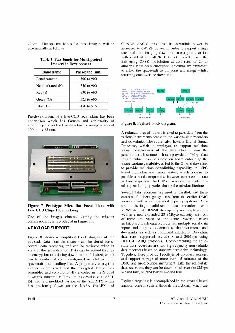
Pre-development of a five-CCD focal plane has been undertaken which has flatness and coplanarity of around 5 µm over the five detectors, covering an area of 100 mm x 25 mm.
Figure 7 Prototype Micro-flat Focal Plane with Five CCD Chips 100 mm Long
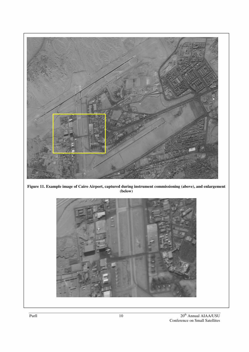
One of the images obtained during the mission commissioning is reproduced in Figure 11.
4 PAYLOAD SUPPORT
Figure 8 shows a simplified block diagram of the payload. Data from the imagers can be stored across several data recorders, and can be retrieved when in view of the groundstation. Data can be routed through an encryption unit during downlinking if desired, which can be controlled and reconfigured in orbit over the spacecraft data handling bus. A proprietary encryption method is employed, and the encrypted data is then scrambled and convolutionally encoded in the X-band downlink transmitter. This unit is developed at SSTL [5], and is a modified version of the SIL XTX which has preciously flown on the NASA GALEX and
CONAE SAC-C missions. Its downlink power is increased to 6W RF power, in order to support a high rate, real-time imaging downlink, into a groundstation with a G/T of ~30.5dB/K. Data is transmitted over the link using QPSK modulation at data rates of 20 or 40Mbps. Near omni-directional antennas are employed to allow the spacecraft to off-point and image whilst returning data over the downlink.
������ ������ ��� ���
��� �� �� �� �� ���
��� ���
������ ��
�������������� ��������������
����������
� !�" � !�" �" !�"
��� �#$�%��������������#�%����� #���#$���$���������#�%���� �� ��&���$���&��$� �#����#��'�#(���
� ���)�#���������&�������� �($���*�����$����&�������� ����#��%��#�*(���
Figure 8: Payload block diagram.
A redundant set of routers is used to pass data from the various instruments across to the various data recorders and downlinks. The router also hosts a Digital Signal Processor, which is employed to support real-time image compression of the data stream from the panchromatic instrument. It can provide a 40Mbps data stream, which can be stored on board enhancing the image capture capability, or fed to the X-band downlink to provide real-time downlinking capability. A JPG based algorithm was implemented, which appears to provide a good compromise between compression rate and image quality. The DSP software can be loaded on-orbit, permitting upgrades during the mission lifetime.
Several data recorders are used in parallel, and these combine full heritage systems from the earlier DMC missions with some upgraded capacity systems. As a result, heritage solid-state data recorders with 512Mbyte and 1024Mbyte capacity are employed, as well as a new expanded 2048Mbyte capacity unit. All of these are based on the same PowerPC based architecture. Each data recorder has multiple serial data inputs and outputs to connect to the instruments and downlinks, as well as command interfaces. Downlink data rates supported include 8 and 20Mbps using HDLC-IP ARQ protocols. Complementing the solid-state data recorders are two high-capacity non-volatile data recorders based on standard hard-drive technology. Together, these provide 120Gbyte of on-board storage, and support storage of more than 15 minutes of the DMC and hi-resolution instrument. Like the solid-state data recorders, they can be downlinked over the 8Mbps S-band link, or 20/40Mbps X-band link. Payload targeting is accomplished in the ground based mission control system through predictions, which are
Purll 8 20th Annual AIAA/USU Conference on Small Satellites
refined in orbit once near the target using the on-board GPS receiver.
The spacecraft supports 6 basic modes of payload operation. In the primary mode of operation the spacecraft is operated in nadir mode in a systematic mapping campaign. The high-resolution imager is operated for over 15 continuous minutes in real-time through the data compressor, and downlinked at 40Mbps. The DMC instrument is operated in data storage mode until reaching its storage limits. Other modes include:-
• Operation of the high-resolution imager in Store and Forward mode, with the DMC imager operating in two possible modes (illustrated in Figure 9 for a 1Gbyte data buffer):- o Operation of the DMC instrument in a
narrower swath mode to support real-time downlinking via the 20Mbps X-band downlink.
o Operation of the DMC instrument in wide swath mode to support pseudo-real-time downlinking using the data recorder as a buffer and downlinking via the 20Mbps X-band downlink.
• The DMC instrument data is recorded in the SSDR, for later downlinking over the S-band payload downlink.
Downlinking data stored in the Data Recorders is available on the downlink
600km
400 sec or 3011 km83 sec or 627 km
600km125km
Figure 9. DMC real time modes
Some additional modes, such as operations in off-pointed mode, or storing compressed data on the data recorders, can also be supported within the constraints of the available on-board power and storage resources.
With the ability to operate the HRI for 15 minutes each orbit, dividing the spacecraft cost by its image delivery capacity the spacecraft for its lifetime shows that ultimately 24x24km pre-processed scenes at 4m GSD could be generated for about US$2 each. The value of such data is of course greater for satellites operated in constellation [6], where the time to revisit the same scene is reduced to daily or even hourly. In practice the spacecraft will be operated only at a fraction of its full capacity, and in a commercial situation the same scenes might be sold many times, but would need to consider profits and the overheads for the processing and distribution. Of course the spacecraft also delivers additional scenes from the DMC payload.
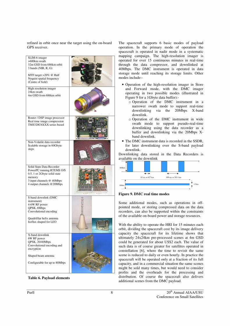
SLIM-6 imager >600km swath 32m GSD from 686km orbit 3 bands (NIR, R, G) MTF target >20% @ Half Nyquist spatial frequency (Centre of field)
High resolution imager 24km swath 4m GSD from 686km orbit
Router / DSP image processor Real time image compression TMS320C6XXX series based
Non-Volatile data recorder Scalable storage in 60Gbyte steps
Solid State Data Recorder PowerPC running RTEMS O/S 0.5, 1 or 2Gbyte solid state memory 3 input channels @ 40Mbps 4 output channels @20Mbps
S-band downlink (DMC instrument) 4-6W RF power QPSK, 8Mbps Convolutional encoding Quadrifilar helix antenna Isoflux shaped for LEO
X-band downlink 6W RF power QPSK, 20/40Mbps Convolutional encoding and encryption Shaped beam antenna Configurable for up to 80Mbps
Table 6. Payload elements
Purll 9 20th Annual AIAA/USU Conference on Small Satellites
5 CONCLUSIONS
Increasingly sophisticated small Earth Observation satellite missions are becoming feasible. Affordable mission solutions now make it possible to target specific user groups and applications. For users this means higher priority service, and operational tools dedicated at their specific needs. The Beijing-1 mission is providing an operational service in orbit. A design philosophy will allow both the platform and instrument to be scaled to address various different and emerging applications. Specifically, the use of such spacecraft solutions in constellations is highly promising to address high temporal resolution requirements.
6 ACKNOWLEDGEMENTS
The authors gratefully acknowledge the work of many colleagues at SSTL on the China Mapping Telescope and the Beijing-1 satellite projects. The work was carried out with partial financial support from the British National Space Centre.
7 REFERENCES
1. “First results from the disaster monitoring constellation”, Alex da Silva Curiel, Lee Boland,
John Cooksley, Mohammed Bekhti, Paul Stephens, Wei Sun, Prof. Sir Martin Sweeting, IAA-B4-1302, 4th IAA Symposium on Small Satellites for Earth Observation , Berlin, April 2003.
2. “Alsat-1 first year in orbit”, John Cooksley et al, IAF Bremen Germany, October 2003, IAC-03-B.1.09
3. “BILSAT-1: First Year in Orbit- Operations and Lessons Learned”, Gokhan Yuksel, Hakan Urhan, Onder Belce, Neville Bean, Alex da Silva Curiel, Luis Gomes, Andy Bradford, 18th Annual AIAA/USU Conference on Small Satellites, Logan Utah, August 2004 “TopSat - High Resolution Imaging From a Small Satellite”, P. Brooks, 15th Annual Small Satellite Conference, Logan UT, US, Aug 2001
4. “An EO Constellation based on the TopSat Microsatellite: Global Daily Revisit at 2.5 metres”, Alex Wicks et al, AIAA/USU conference on small satellites, Logan Utah USA, August 2001 2001, SSC01-I-6.
5. “Flexible Low Cost X-Band Transmitter” ,Dr. Peter Garner, Kevin Maynard, Dr. Stephen Hodgart, Martin Pointer, ESOC TT&C conference, Sep04, Darmstadt
6. The next generation DMC small satellite platform for high-resolution imaging, IAC05-B5.4.01, IAF, Fukuoka, Japan., Oct 2005
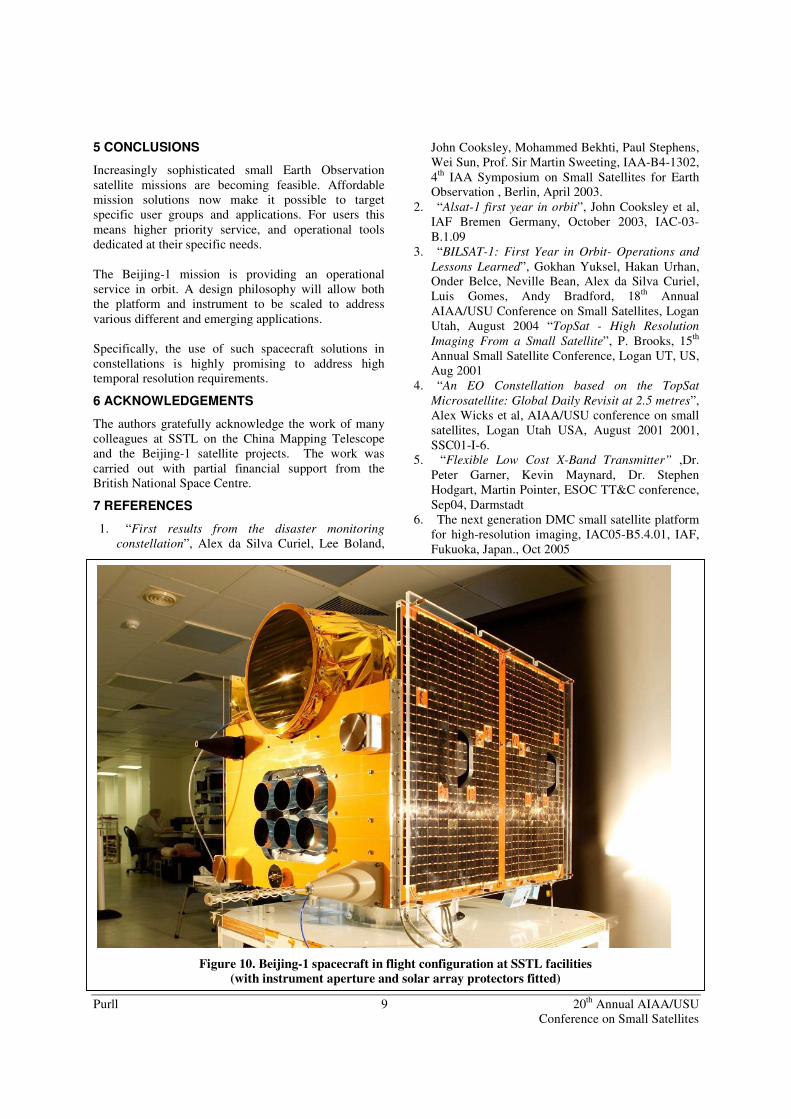
Figure 10. Beijing-1 spacecraft in flight configuration at SSTL facilities (with instrument aperture and solar array protectors fitted)
Purll 10 20th Annual AIAA/USU Conference on Small Satellites
Figure 11. Example image of Cairo Airport, captured during instrument commissioning (above), and enlargement (below)