Embed Size (px)
Citation preview
masibus
User’s Manual
SSIINNGGLLEE LLOOOOPP PPIIDD CCOONNTTRROOLLLLEERR
WWiitthh AAUUTTOO TTUUNNEE
LLCC55229966--AATT
LLCC55224488EE--AATT
Masibus Automation & Instrumentation Pvt. Ltd. B/30, GIDC Electronics Estate,
Sector-25, Gandhinagar-382044, Gujarat, India +91 79 23287275-79 +91 79 23287281-82
Email: [email protected] Web: www.masibus.com
Model: LC5296-AT /LC5248E-AT masibus Doc. Ref. no. : - m61C/om/301
Issue no. 09
User‟s Manual Page 2 of 44
Contents
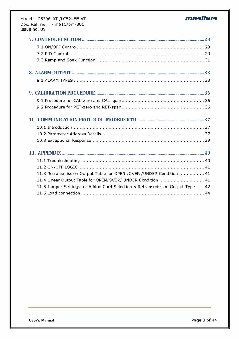
1. INTRODUCTION ........................................................................................................................... 4
Foreword ........................................................................................................ 4
Notice ............................................................................................................ 4
Trademarks .................................................................................................... 4
Checking the Contents of the Package ................................................................ 4
Product Ordering Code ..................................................................................... 4
List of Accessories ........................................................................................... 5
Safety Precautions ........................................................................................... 5
2. SPECIFICATIONS ......................................................................................................................... 6
2.1 Inputs ....................................................................................................... 6
2.2 Display& Keys ............................................................................................ 7
2.3 Output Types ............................................................................................. 7
2.4 Communication Details ............................................................................... 8
2.5 Power Supply............................................................................................. 8
2.6 Environmental Conditions ............................................................................ 9
3. PHYSICAL SPECIFICATIONS &MOUNTING DETAILS ..................................................... 10
3.1 LC5296-AT .............................................................................................. 10
3.3 LC5248E-AT ............................................................................................ 10
4. TERMINAL CONNECTIONS .................................................................................................... 11
4.1 LC5296-AT .............................................................................................. 11
4.3 LC5248E-AT ............................................................................................ 12
4.4 How to connect wires ................................................................................ 12
5. FRONT PANEL DETAILS ......................................................................................................... 14
5.1 Front Panel Description of LC5296-AT ......................................................... 15
5.3 Front Panel Description of LC5248E-AT ....................................................... 16
6. MENU LAYOUT .......................................................................................................................... 17
6.1 Menu Layout for LC5296-AT ...................................................................... 17
6.2 Menu Layout for LC5248E-AT ..................................................................... 18
6.3 RUN Time Indication/Function .................................................................... 20
6.4 Set Point Setting ...................................................................................... 21
6.5AUTO TUNE MODE ..................................................................................... 21
6.6 CONFIGURATION MODE ............................................................................ 22
6.7 CALIBRATIONMODE .................................................................................. 26
Model: LC5296-AT /LC5248E-AT masibus Doc. Ref. no. : - m61C/om/301
Issue no. 09
User‟s Manual Page 3 of 44
7. CONTROL FUNCTION .............................................................................................................. 28
7.1 ON/OFF Control........................................................................................ 28
7.2 PID Control ............................................................................................. 29
7.3 Ramp and Soak Function ........................................................................... 31
8. ALARM OUTPUT ....................................................................................................................... 33
8.1 ALARM TYPES .......................................................................................... 33
9. CALIBRATION PROCEDURE .................................................................................................. 36
9.1 Procedure for CAL-zero and CAL-span ......................................................... 36
9.2 Procedure for RET-zero and RET-span ......................................................... 36
10. COMMUNICATION PROTOCOL–MODBUS RTU ............................................................. 37
10.1 Introduction ........................................................................................... 37
10.2 Parameter Address Details ....................................................................... 37
10.3 Exceptional Response ............................................................................. 39
11. APPENDIX ................................................................................................................................ 40
11.1 Troubleshooting ..................................................................................... 40
11.2 ON-OFF LOGIC ....................................................................................... 41
11.3 Retransmission Output Table for OPEN /OVER /UNDER Condition ................. 41
11.4 Linear Output Table for OPEN/OVER/ UNDER Condition ............................... 41
11.5 Jumper Settings for Addon Card Selection & Retransmission Output Type ...... 42
11.6 Load connection ..................................................................................... 44
Model: LC5296-AT /LC5248E-AT masibus Doc. Ref. no. : - m61C/om/301
Issue no. 09
User‟s Manual Page 4 of 44
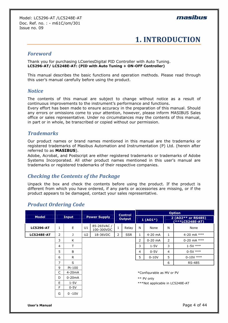
1. INTRODUCTION
Foreword
Thank you for purchasing LCseriesDigital PID Controller with Auto Tuning. LC5296-AT/ LC5248E-AT: (PID with Auto Tuning + ON-OFF Controller)
This manual describes the basic functions and operation methods. Please read through
this user‟s manual carefully before using the product.
Notice
The contents of this manual are subject to change without notice as a result of
continuous improvements to the instrument‟s performance and functions.
Every effort has been made to ensure accuracy in the preparation of this manual. Should
any errors or omissions come to your attention, however, please inform MASIBUS Sales
office or sales representative. Under no circumstances may the contents of this manual,
in part or in whole, be transcribed or copied without our permission.
Trademarks
Our product names or brand names mentioned in this manual are the trademarks or
registered trademarks of Masibus Automation and Instrumentation (P) Ltd. (herein after
referred to as MASIBUS).
Adobe, Acrobat, and Postscript are either registered trademarks or trademarks of Adobe
Systems Incorporated. All other product names mentioned in this user's manual are
trademarks or registered trademarks of their respective companies.
Checking the Contents of the Package
Unpack the box and check the contents before using the product. If the product is
different from which you have ordered, if any parts or accessories are missing, or if the
product appears to be damaged, contact your sales representative.
Product Ordering Code
Model Input Power Supply Control Output
Option
1 (AO1*) 2 (AO2** or RS485) (***LC5248E-AT)
LC5296-AT 1 E U1 85-265VAC / 100-300VDC
1 Relay N None N None
LC5248E-AT 2 J U2 18-36VDC 2 SSR 1 4-20 mA 1 4-20 mA ***
3 K
2 0-20 mA 2 0-20 mA ***
4 T
3 1-5V 3 1-5V ***
5 B
4 0-5V 4 0-5V ***
6 R
5 0-10V 5 0-10V ***
7 S
6 RS-485
9 Pt-100
C 4-20mA
*Configurable as MV or PV
D 0-20mA
** PV only
E 1-5V
***Not applicable in LC5248E-AT
F 0-5V
G 0 -10V
Model: LC5296-AT /LC5248E-AT masibus Doc. Ref. no. : - m61C/om/301
Issue no. 09
User‟s Manual Page 5 of 44
The unit has a nameplate affixed to the one side of the enclosure.Check the model and
suffix codes inscribed on the nameplate to confirm that the product received is that
which was ordered.
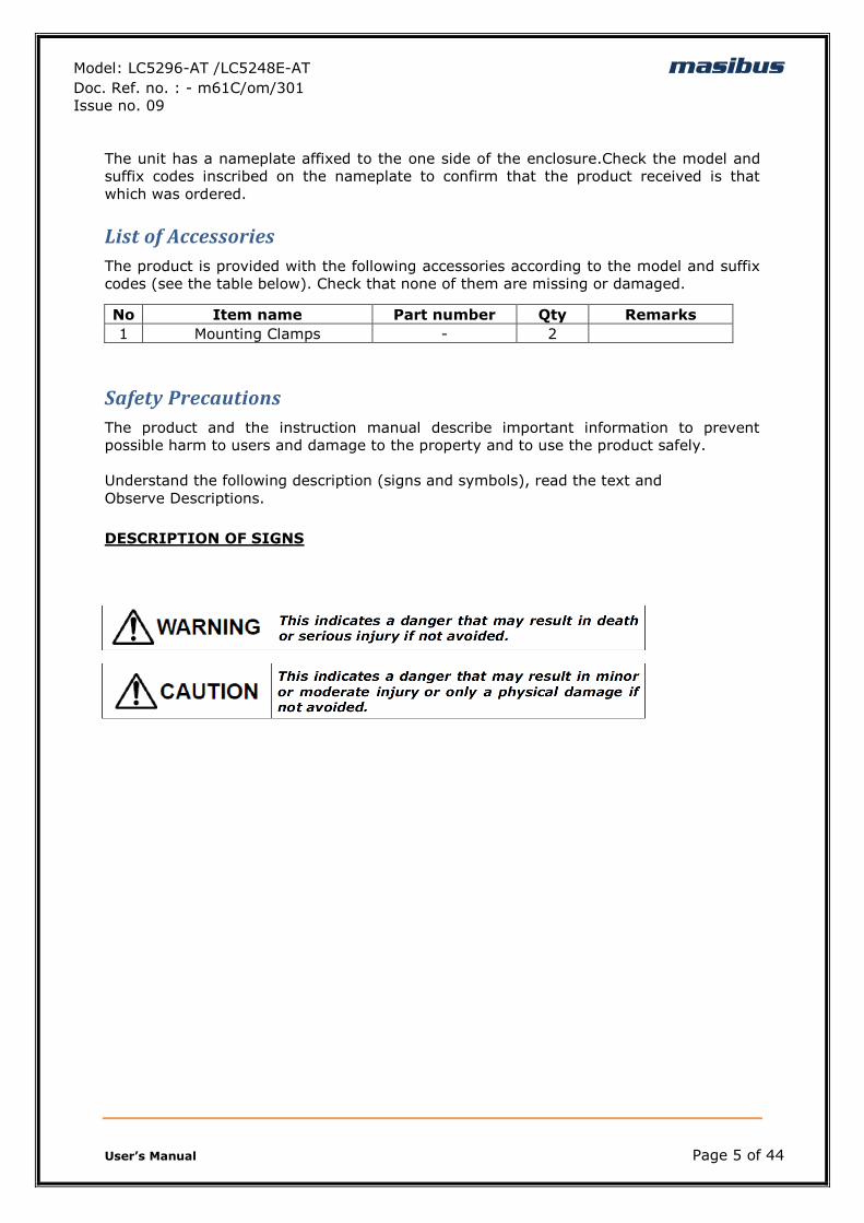
List of Accessories
The product is provided with the following accessories according to the model and suffix
codes (see the table below). Check that none of them are missing or damaged.
No Item name Part number Qty Remarks
1 Mounting Clamps - 2
Safety Precautions
The product and the instruction manual describe important information to prevent
possible harm to users and damage to the property and to use the product safely.
Understand the following description (signs and symbols), read the text and
Observe Descriptions.
DESCRIPTION OF SIGNS
Model: LC5296-AT /LC5248E-AT masibus Doc. Ref. no. : - m61C/om/301
Issue no. 09
User‟s Manual Page 6 of 44
2. SPECIFICATIONS
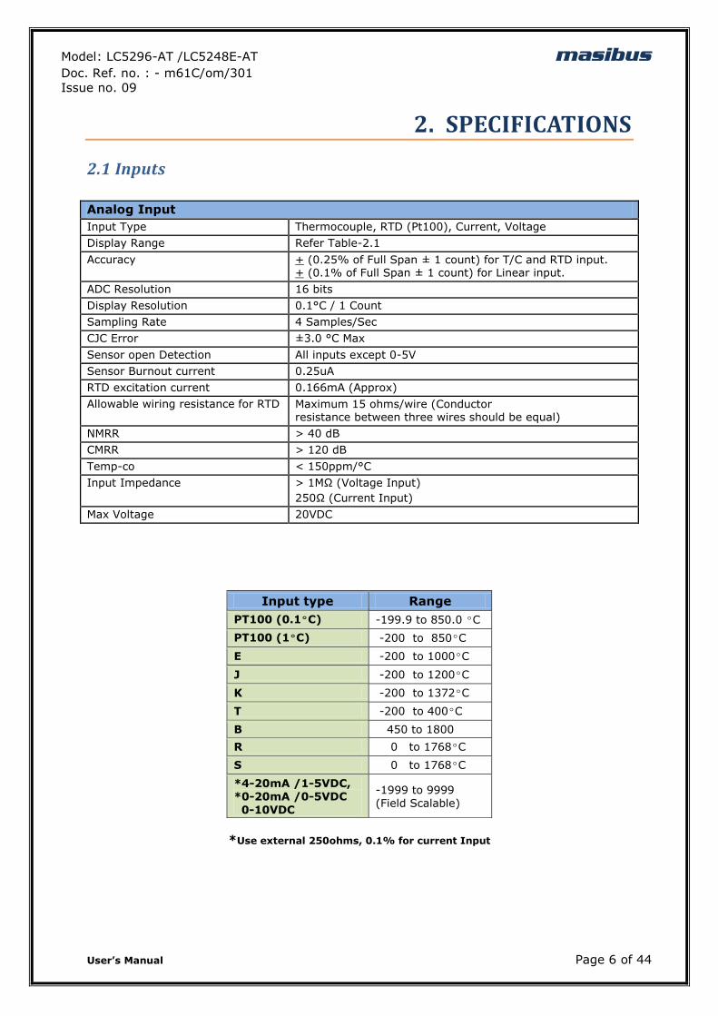
2.1 Inputs
Analog Input
Input Type Thermocouple, RTD (Pt100), Current, Voltage
Display Range Refer Table-2.1
Accuracy + (0.25% of Full Span ± 1 count) for T/C and RTD input. + (0.1% of Full Span ± 1 count) for Linear input.
ADC Resolution 16 bits
Display Resolution 0.1°C / 1 Count
Sampling Rate 4 Samples/Sec
CJC Error ±3.0 °C Max
Sensor open Detection All inputs except 0-5V
Sensor Burnout current 0.25uA
RTD excitation current 0.166mA (Approx)
Allowable wiring resistance for RTD Maximum 15 ohms/wire (Conductor resistance between three wires should be equal)
NMRR > 40 dB
CMRR > 120 dB
Temp-co < 150ppm/°C
Input Impedance > 1MΩ (Voltage Input)
250Ω (Current Input)
Max Voltage 20VDC
*Use external 250ohms, 0.1% for current Input
Input type Range
PT100 (0.1ºC) -199.9 to 850.0 ºC
PT100 (1ºC) -200 to 850ºC
E -200 to 1000ºC
J -200 to 1200ºC
K -200 to 1372ºC
T -200 to 400ºC
B 450 to 1800
R 0 to 1768ºC
S 0 to 1768ºC
*4-20mA /1-5VDC, *0-20mA /0-5VDC
0-10VDC
-1999 to 9999 (Field Scalable)
Model: LC5296-AT /LC5248E-AT masibus Doc. Ref. no. : - m61C/om/301
Issue no. 09
User‟s Manual Page 7 of 44
2.2 Display& Keys
Model Display Specification
LC5296-AT
PV Display 4-Digit, 7-Segment, Red, Character height of 0.56”
SV / Parameter Display 4-Digit, 7-Segment, Green, Character height of 0.40”
Status Indication Individual RED Led for Relay, SSR Output, Manual & Communication Status
LC5248E-AT
PV Display 4-Digit, 7-Segment, Red, Character height of 0.40”
SV / Parameter Display 4-Digit, 7-Segment, Green, Character height of
0.28”
Status Indication
Individual RED Led‟s for Relay Status, SSR Output, Manual & Communication Status
2.3 Output Types
Output types are software selectable from the Key board or Modbus(LC5296-AT&LC5248E-ATOnly).
Model Output Type Description
LC5296-
AT/LC5248E-AT
Relay Output
2 Relays
Relay-1 For PID or ON-OFF Controlling. Used as Alarm-1 Output if Output Type is
Linear
Relay-2 Alarm-2 Output
SSR Output * Voltage Pulse Output Available at Terminals of Relay-1
Linear Output Available at Terminals of Retransmission-1. Linear Output Type as per selection in Retransmission-1 Output Type.
Also, Output Direction [Direct(Cooling) /Reverse(Heating)] is selectable from software. * For LC5296-AT, at a time unit can support Relay or SSR Output. (Factory settable)
(Specify in Order Code)
Relay Output
Relays 1
Type Single Change over
Three Terminals (C, NO, NC)
Rating 2A @ 230VAC / 30VDC
Pulse Output (SSR)
Output signal Voltage Pulse Output
Output signal On-condition 11VDC or more
Off-condition 2VDC or less
Resolution 10 ms
Model: LC5296-AT /LC5248E-AT masibus Doc. Ref. no. : - m61C/om/301
Issue no. 09
User‟s Manual Page 8 of 44
Linear Output
Output Signal Voltage (0-5VDC, 1-5VDC, 0-10VDC) @3kΩ Min
Current (4-20mADC, 0-20mADC) @500Ω Max
Retransmission Output
Number of output 1 (@Retransmission-2)(For Linear Output Type) or
*2 (@Retransmisswion-1&2)(For Relay 0r SSR Output Type)
Output According to Process Value
Output Signal 4-20mA/ 0-20mA/1-5VDC/ 0-5VDC / 0-10V DC
Load resistance
For Current o/p
For Voltage o/p
<500Ω
>3KΩ
Output accuracy ±0.25% of span
*Not applicable for LC5248E-AT
Alarm Output
Number of Outputs 2 if Output Type is Linear(@Relay-1&2), 1 if Output Type is Relay or SSR(@Relay-2) Control relays are available as alarm outputs
Output signal Three terminals (NC, NO, and C)
Purpose Alarm output and others.
(See Alarm and Digital outputs function)
Relay contact rating 250 V AC or 30 V DC, 2A (resistive load)
Loop Power Supply
Supply Voltage 24VDC (±1V) @26mAwith Inbuilt Short Circuit Protection
Minimum load resistance 800 ohms
2.4 Communication Details
Communication
Interface RS485 (2 Wire)
Protocol Modbus-RTU
Baud rate 9600, 19200, 38400 bps
2.5 Power Supply
Standard 85-265VAC/ 100-300VDC
Optional 18-36VDC
Power consumption <10 VA (LC5296-AT)
<5 VA (LC5248E-AT)
Data backup Non-volatile memory (can be written up to 100000 times)
Isolation (Withstanding voltage)
Between primary terminals* and secondary terminals**:
At least 1500 V AC for 1 minute
Between primary terminals* and grounding terminal:
At least 1500 V AC for 1 minute
Between grounding terminal and secondary terminals**:
At least 1500 V AC for 1 minute
Model: LC5296-AT /LC5248E-AT masibus Doc. Ref. no. : - m61C/om/301
Issue no. 09
User‟s Manual Page 9 of 44
Between secondary terminals**:
At least 500 V AC for 1 minute
* Primary terminals indicate power terminals and relay output terminals.
** Secondary terminals indicate analog I/O signal and Communication O/P.
Insulation resistance:20MΩ or more at 500 V DC between power terminals and grounding
terminal.
2.6 Environmental Conditions
TEMPCO For Input to PV Display < 100ppm. FOR Display to
Retransmission and Control output < 100ppm
Humidity 30% to 95% RH (Non-Condensing)
Instrument Warm-up Time Approx. 15 minutes
Ambient temperature 0 to 55°C
Storage Temperature 0 to 80°C
Model: LC5296-AT /LC5248E-AT masibus Doc. Ref. no. : - m61C/om/301
Issue no. 09
User‟s Manual Page 10 of 44
3. PHYSICAL SPECIFICATIONS &MOUNTING DETAILS
3.1 LC5296-AT
Front Bezel 96 x 96 mm
Panel Cutout 92mm(+0.8) x 92mm(+0.8)
Depth Behind The Panel 65 mm withTerminal
Weight 300g Approx.
Encloser Material ABS
Encloser Protection IP20
Terminal Cable Size 2.5 mm2
Fig 3.1: Mounting Details for LC5296-AT
3.3 LC5248E-AT
Front Bezel 48 x 48 mm
Panel Cutout 44 x 44 mm
Depth Behind The Panel 115mm
Weight 200g Approx.
Encloser Material ABS
Encloser Protection IP20
Terminal Cable Size 2.5 mm2
Fig 3.3: Mounting Details for LC5248E-AT
Model: LC5296-AT /LC5248E-AT masibus Doc. Ref. no. : - m61C/om/301
Issue no. 09
User‟s Manual Page 11 of 44
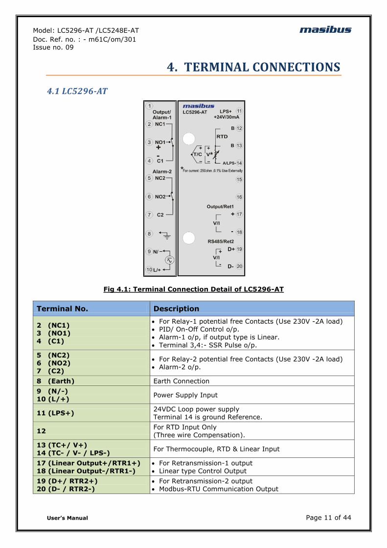
4. TERMINAL CONNECTIONS
4.1 LC5296-AT
Fig 4.1: Terminal Connection Detail of LC5296-AT
Terminal No. Description
2 (NC1)
3 (NO1)
4 (C1)
For Relay-1 potential free Contacts (Use 230V -2A load)
PID/ On-Off Control o/p.
Alarm-1 o/p, if output type is Linear.
Terminal 3,4:- SSR Pulse o/p.
5 (NC2)
6 (NO2)
7 (C2)
For Relay-2 potential free Contacts (Use 230V -2A load)
Alarm-2 o/p.
8 (Earth) Earth Connection
9 (N/-)
10 (L/+) Power Supply Input
11 (LPS+) 24VDC Loop power supply
Terminal 14 is ground Reference.
12 For RTD Input Only
(Three wire Compensation).
13 (TC+/ V+)
14 (TC- / V- / LPS-) For Thermocouple, RTD & Linear Input
17 (Linear Output+/RTR1+)
18 (Linear Output-/RTR1-)
For Retransmission-1 output
Linear type Control Output
19 (D+/ RTR2+)
20 (D- / RTR2-)
For Retransmission-2 output
Modbus-RTU Communication Output
Model: LC5296-AT /LC5248E-AT masibus Doc. Ref. no. : - m61C/om/301
Issue no. 09
User‟s Manual Page 12 of 44
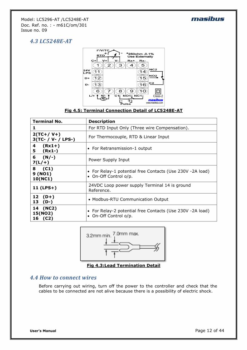
4.3 LC5248E-AT
Fig 4.5: Terminal Connection Detail of LC5248E-AT
Terminal No. Description
1 For RTD Input Only (Three wire Compensation).
2(TC+/ V+)
3(TC- / V- / LPS-) For Thermocouple, RTD & Linear Input
4 (Rx1+)
5 (Rx1-) For Retransmission-1 output
6 (N/-)
7(L/+) Power Supply Input
8 (C1)
9 (NO1)
10(NC1)
For Relay-1 potential free Contacts (Use 230V -2A load)
On-Off Control o/p.
11 (LPS+) 24VDC Loop power supply Terminal 14 is ground
Reference.
12 (D+)
13 (D-) Modbus-RTU Communication Output
14 (NC2)
15(NO2)
16 (C2)
For Relay-2 potential free Contacts (Use 230V -2A load)
On-Off Control o/p.
Fig 4.3:Lead Termination Detail
4.4 How to connect wires
Before carrying out wiring, turn off the power to the controller and check that the
cables to be connected are not alive because there is a possibility of electric shock.
Model: LC5296-AT /LC5248E-AT masibus Doc. Ref. no. : - m61C/om/301
Issue no. 09
User‟s Manual Page 13 of 44
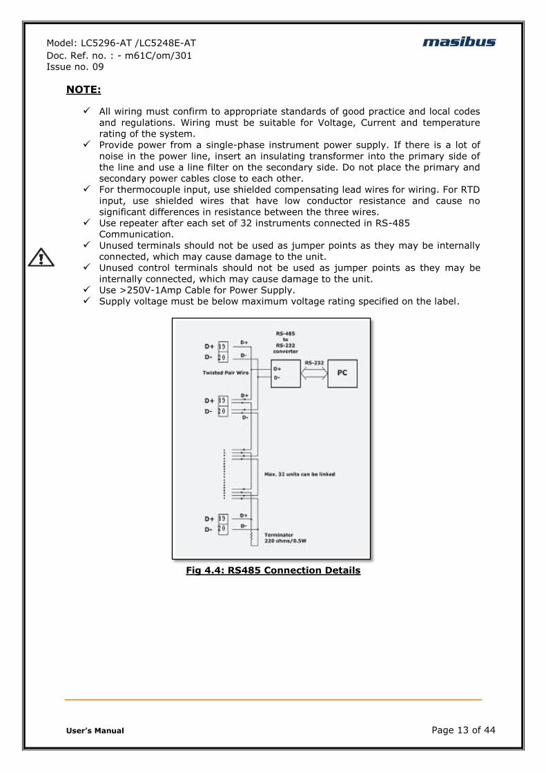
NOTE:
All wiring must confirm to appropriate standards of good practice and local codes
and regulations. Wiring must be suitable for Voltage, Current and temperature
rating of the system.
Provide power from a single-phase instrument power supply. If there is a lot of
noise in the power line, insert an insulating transformer into the primary side of
the line and use a line filter on the secondary side. Do not place the primary and
secondary power cables close to each other.
For thermocouple input, use shielded compensating lead wires for wiring. For RTD
input, use shielded wires that have low conductor resistance and cause no
significant differences in resistance between the three wires.
Use repeater after each set of 32 instruments connected in RS-485
Communication.
Unused terminals should not be used as jumper points as they may be internally
connected, which may cause damage to the unit.
Unused control terminals should not be used as jumper points as they may be
internally connected, which may cause damage to the unit.
Use >250V-1Amp Cable for Power Supply.
Supply voltage must be below maximum voltage rating specified on the label.
Fig 4.4: RS485 Connection Details
Model: LC5296-AT /LC5248E-AT masibus Doc. Ref. no. : - m61C/om/301
Issue no. 09
User‟s Manual Page 14 of 44
5. FRONT PANEL DETAILS
Model: LC5296-AT /LC5248E-AT masibus Doc. Ref. no. : - m61C/om/301
Issue no. 09
User‟s Manual Page 15 of 44
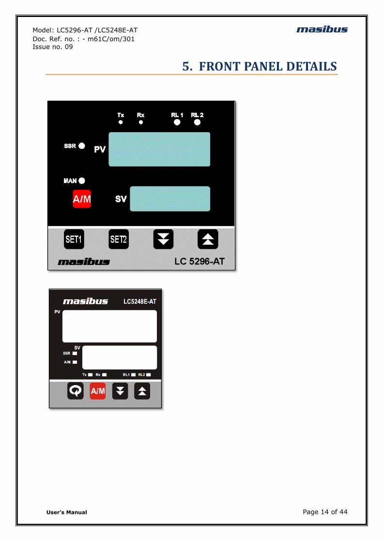
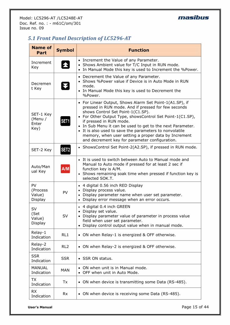
5.1 Front Panel Description of LC5296-AT
Name of Part
Symbol Function
Increment
Key
Increment the Value of any Parameter.
Shows Ambient value for T/C Input in RUN mode.
In Manual Mode this key is used to Increment the %Power.
Decremen
t Key
Decrement the Value of any Parameter.
Shows %Power value if Device is in Auto Mode in RUN
mode.
In Manual Mode this key is used to Decrement the
%Power.
SET-1 Key
(Menu /
Enter
Key)
For Linear Output, Shows Alarm Set Point-1(A1.SP), if
pressed in RUN mode. And if pressed for few seconds
shows Control Set Point-1(C1.SP).
For Other Output Type, showsControl Set Point-1(C1.SP),
if pressed in RUN mode.
In Sub Menu it can be used to get to the next Parameter.
It is also used to save the parameters to nonvolatile
memory, when user setting a proper data by Increment
and decrement key for parameter configuration.
SET-2 Key
ShowsControl Set Point-2(A2.SP), if pressed in RUN mode.
Auto/Man
ual Key
It is used to switch between Auto to Manual mode and
Manual to Auto mode if pressed for at least 2 sec if
function key is A/M.
Shows remaining soak time when pressed if function key is
selected SOK.T.
PV
(Process
Value)
Display
PV
4 digital 0.56 inch RED Display
Display process value.
Display parameter name when user set parameter.
Display error message when an error occurs.
SV
(Set
Value)
Display
SV
4 digital 0.4 inch GREEN
Display set value.
Display parameter value of parameter in process value
field when user set parameter.
Display control output value when in manual mode.
Relay-1
Indication RL1 ON when Relay-1 is energized & OFF otherwise.
Relay-2
Indication RL2 ON when Relay-2 is energized & OFF otherwise.
SSR
Indication SSR SSR ON status.
MANUAL
Indication MAN
ON when unit is in Manual mode.
OFF when unit in Auto Mode.
TX
Indication Tx ON when device is transmitting some Data (RS-485).
RX
Indication Rx ON when device is receiving some Data (RS-485).
Model: LC5296-AT /LC5248E-AT masibus Doc. Ref. no. : - m61C/om/301
Issue no. 09
User‟s Manual Page 16 of 44
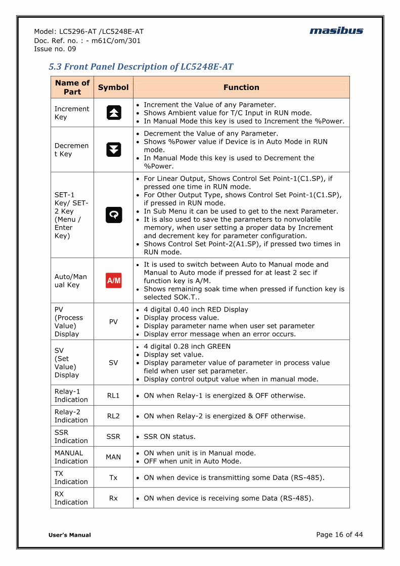
5.3 Front Panel Description of LC5248E-AT
Name of Part
Symbol Function
Increment
Key
Increment the Value of any Parameter.
Shows Ambient value for T/C Input in RUN mode.
In Manual Mode this key is used to Increment the %Power.
Decremen
t Key
Decrement the Value of any Parameter.
Shows %Power value if Device is in Auto Mode in RUN
mode.
In Manual Mode this key is used to Decrement the
%Power.
SET-1
Key/ SET-
2 Key
(Menu /
Enter
Key)
For Linear Output, Shows Control Set Point-1(C1.SP), if
pressed one time in RUN mode.
For Other Output Type, shows Control Set Point-1(C1.SP),
if pressed in RUN mode.
In Sub Menu it can be used to get to the next Parameter.
It is also used to save the parameters to nonvolatile
memory, when user setting a proper data by Increment
and decrement key for parameter configuration.
Shows Control Set Point-2(A1.SP), if pressed two times in
RUN mode.
Auto/Man
ual Key
It is used to switch between Auto to Manual mode and
Manual to Auto mode if pressed for at least 2 sec if
function key is A/M.
Shows remaining soak time when pressed if function key is
selected SOK.T..
PV
(Process
Value)
Display
PV
4 digital 0.40 inch RED Display
Display process value.
Display parameter name when user set parameter
Display error message when an error occurs.
SV
(Set
Value)
Display
SV
4 digital 0.28 inch GREEN
Display set value.
Display parameter value of parameter in process value
field when user set parameter.
Display control output value when in manual mode.
Relay-1
Indication RL1 ON when Relay-1 is energized & OFF otherwise.
Relay-2
Indication RL2 ON when Relay-2 is energized & OFF otherwise.
SSR
Indication SSR SSR ON status.
MANUAL
Indication MAN
ON when unit is in Manual mode.
OFF when unit in Auto Mode.
TX
Indication Tx ON when device is transmitting some Data (RS-485).
RX
Indication Rx ON when device is receiving some Data (RS-485).
Model: LC5296-AT /LC5248E-AT masibus Doc. Ref. no. : - m61C/om/301
Issue no. 09
User‟s Manual Page 17 of 44
6. MENU LAYOUT
6.1 Menu Layout for LC5296-AT
Model: LC5296-AT /LC5248E-AT masibus Doc. Ref. no. : - m61C/om/301
Issue no. 09
User‟s Manual Page 18 of 44
Model: LC5296-AT /LC5248E-AT masibus Doc. Ref. no. : - m61C/om/301
Issue no. 09
User‟s Manual Page 19 of 44
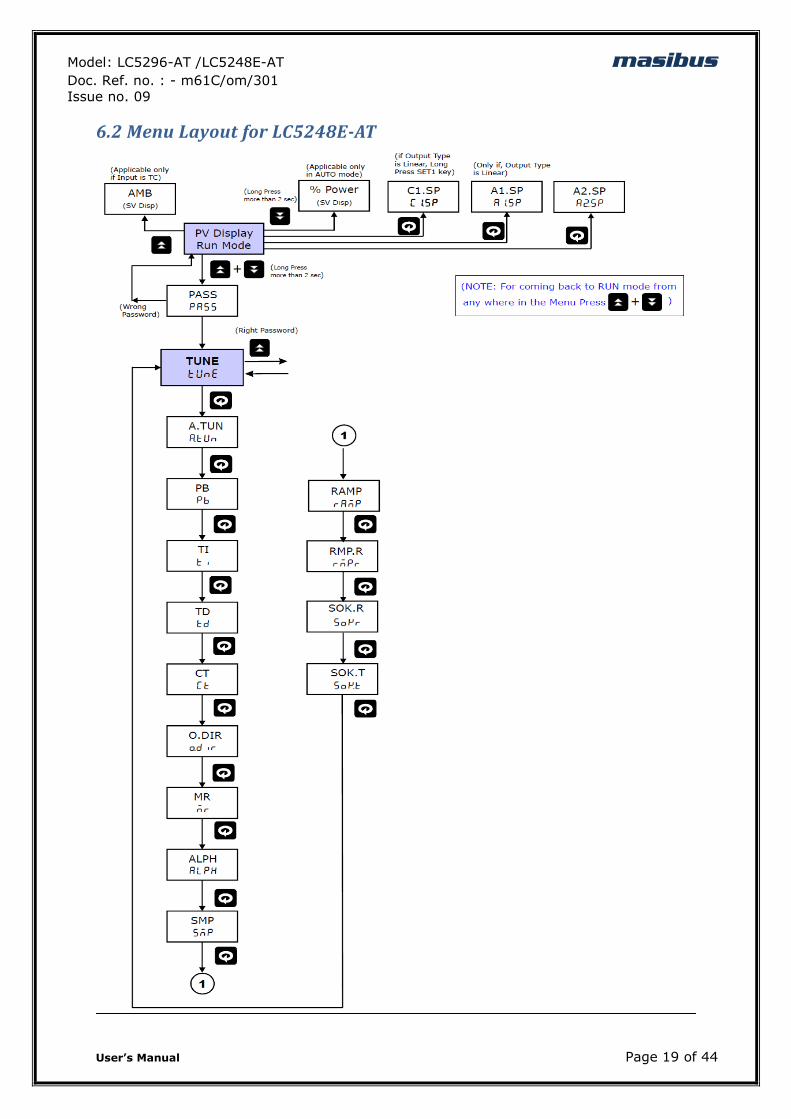
6.2 Menu Layout for LC5248E-AT
Model: LC5296-AT /LC5248E-AT masibus Doc. Ref. no. : - m61C/om/301
Issue no. 09
User‟s Manual Page 20 of 44
Model: LC5296-AT /LC5248E-AT masibus Doc. Ref. no. : - m61C/om/301
Issue no. 09
User‟s Manual Page 21 of 44
6.3 RUN Time Indication/Function
Following parameters can view or change during run time.
Press Decrement key to show percentage power Auto Mode (0.0 to 100.0%)
For Thermocouple input type, Press Increment key to show ambient
temperature.
During manual mode, Increment key and Decrement Key will use to
modify the percentage power.
Press to toggle between AUTO & MANUAL mode or display time.
6.4 Set Point Setting
6.5AUTO TUNE MODE
NOTE: This Menu appear for COP (Control Output Type) other than ONOF (ON-OFF)
Set Point Setting:
Parameter
(PV display) Setting name and
description
Default
value
Shows
only if Symbol Name
C1.SP
(C1.sp) Control Set Point 1
Range Depending on PV
sensor type selected 100 -
A1.SP
(A1.sp) Alarm Set Point 1
Range Depending on PV sensor type selected
100 Output Type is LIN(Linear)
A2.SP
(A2.sp) Alarm Set Point 2
Range Depending on PV
sensor type selected 100 -
AUTOTUNE PARAMETERS
Parameter
(PV display) Setting Name & Description Default
Value Show if Only
Symbol Name
A.TUN
(A.tun) Auto Tune
Start / Stop Auto Tuning Process
yes/no
0 : NO (Stop Auto Tuning) 1 : YES (Start Auto Tuning)
NO Control Type(COP) is PI or PID
PB
(pb)
Proportional Band
Adjust Proportional Band
0 to 9999 or 0.0 to 999.9 10.0
Control Type(COP) is P or PI or PID
TI
(ti) Integral Time
Adjust Integral Time
0 to 1000 60
Control Type(COP) is PI or PID
TD
(td) Derivative Time
Adjust Derivative Time
0 to 180 0
Control Type(COP) is PID
CT
(Ct) Cycle Time Adjust Cycle Time
10
Model: LC5296-AT /LC5248E-AT masibus Doc. Ref. no. : - m61C/om/301
Issue no. 09
User‟s Manual Page 22 of 44
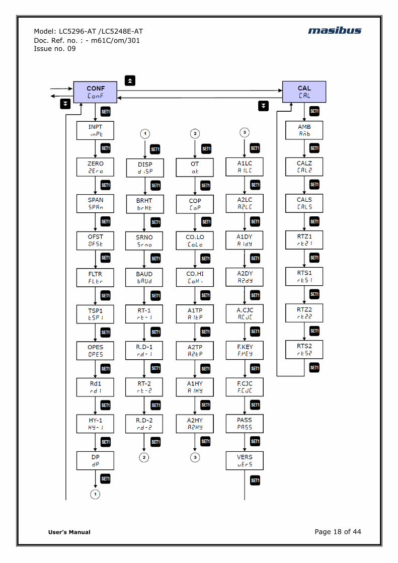
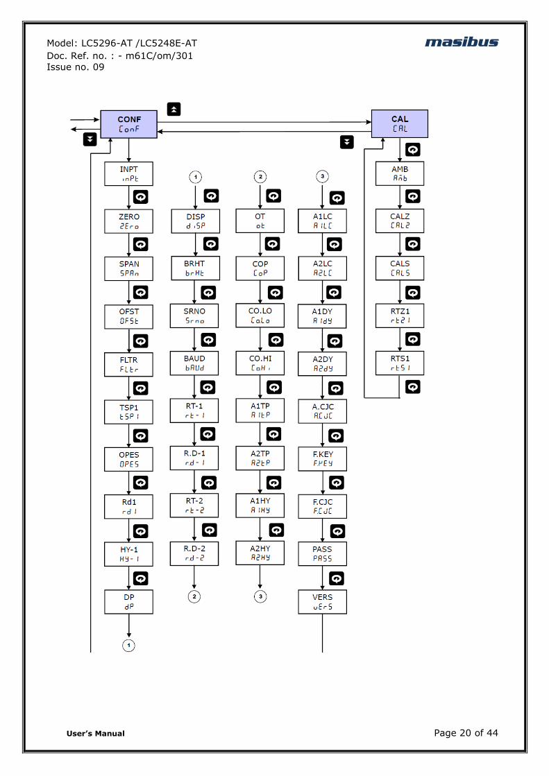
6.6 CONFIGURATION MODE
For, SSR o/p: (1 – 60 sec) Relay o/p: (10 – 300 sec)
O.DIR
(o.dir) Output Direction
Set Output Direction
dir/rev
0 : REV (REVERSE) 1 : DIR (Direct)
0 (REV) Control Type(COP) is P or PI or PID
MR
(mr) Manual Reset
Adjust Manual Reset Value It is used to shift P Band for critical Controlling situations. (Applicable only if Control O/P is “P”)
-(PB/2) to +(PB/2)
EX. If PB = 50, SP = 100, O.DIR = REV
MR = 0MR = 25
PV % POWER PV %POWER
<= 75 100 % <= 100 100 %
100 50 % 125 50 %
>= 125 0 % >= 150 0 %
0 Control Type(COP) is P
ALPH
(alpH) Sampling Rate
Adjust Sampling Rate Its acts like Derivative Factor. It is used to decrease effect of D term in PID output for some critical operating condition
0.01 to 1.00
1.00 Control Type(COP) is PID
SMP
(smp) Sampling Period
Set Sampling Period.
200 /500 /1
0 : 200 ms 1 : 500 ms 2 : 1 sec
0 (200 ms)
Control Type(COP) is PID
RAMP
((Ramp)) Ramp Rate type
none /min.r /hr.r 0:none 1:min.r 2:hr.r
None Not available for Output type OnOFF
Rmp.R
((rmp.r))
Ramp rate value 0.1 to 999.9 Degree per minutes or hour 0.1 Not available for Output type OnOFF
SOK.R
(SOK.R) Soak rate 1 to 9999 minutes 100
Not available for Output type OnOFF
SOK.T
(SOK.T) Soak type
s.hod/s.rst 0:s.hod
1:s.rst
s.rst Not available for Output type OnOFF
CONFIGURATION PARAMETERS
Parameter
(PV display) Setting Name & Description Default
Value Show if Only
Symbol Name
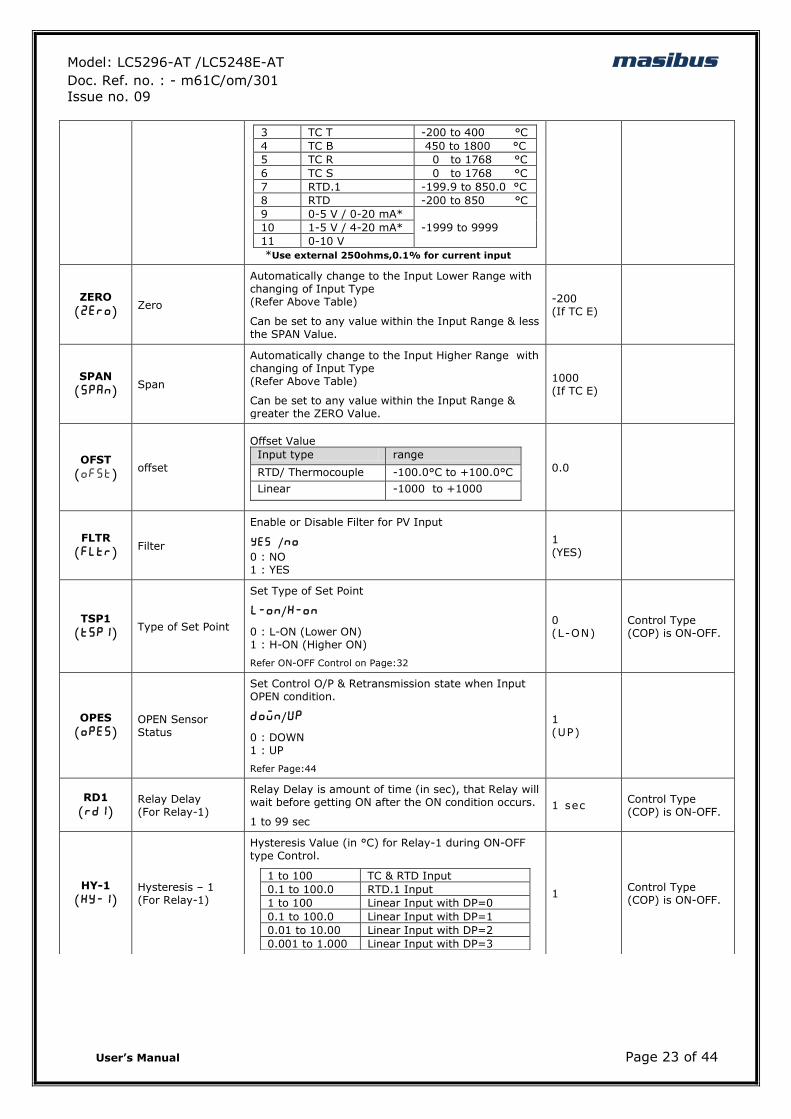
INPT
(inpt) INPUT Type
Set PV Input Type
tC e/tC j /tC K /tC t /tC b /tC r /tC s /rtd.1 /rtd/0-5v /1-5v / 0-10
Value Input Type Range
0 TC E -200 to 1000 °C
1 TC J -200 to 1200 °C
2 TC K -200 to 1372 °C
TC E
Model: LC5296-AT /LC5248E-AT masibus Doc. Ref. no. : - m61C/om/301
Issue no. 09
User‟s Manual Page 23 of 44
3 TC T -200 to 400 °C
4 TC B 450 to 1800 °C
5 TC R 0 to 1768 °C
6 TC S 0 to 1768 °C
7 RTD.1 -199.9 to 850.0 °C
8 RTD -200 to 850 °C
9 0-5 V / 0-20 mA*
-1999 to 9999 10 1-5 V / 4-20 mA*
11 0-10 V
*Use external 250ohms,0.1% for current input
ZERO
(zero) Zero
Automatically change to the Input Lower Range with changing of Input Type (Refer Above Table)
Can be set to any value within the Input Range & less the SPAN Value.
-200 (If TC E)
SPAN
(span) Span
Automatically change to the Input Higher Range with changing of Input Type (Refer Above Table)
Can be set to any value within the Input Range & greater the ZERO Value.
1000 (If TC E)
OFST
(ofst) offset
Offset Value
Input type range
RTD/ Thermocouple -100.0°C to +100.0°C
Linear -1000 to +1000
0.0
FLTR
(fltr) Filter
Enable or Disable Filter for PV Input
yes /no 0 : NO 1 : YES
1 (YES)
TSP1
(tsp1) Type of Set Point
Set Type of Set Point
l-on/H-on
0 : L-ON (Lower ON) 1 : H-ON (Higher ON)
Refer ON-OFF Control on Page:32
0 (L-ON)
Control Type (COP) is ON-OFF.
OPES
(opes)
OPEN Sensor Status
Set Control O/P & Retransmission state when Input OPEN condition.
down/up
0 : DOWN 1 : UP
Refer Page:44
1 (UP)
RD1
(rd1)
Relay Delay (For Relay-1)
Relay Delay is amount of time (in sec), that Relay will wait before getting ON after the ON condition occurs.
1 to 99 sec
1 sec Control Type (COP) is ON-OFF.
HY-1
(Hy-1)
Hysteresis – 1 (For Relay-1)
Hysteresis Value (in °C) for Relay-1 during ON-OFF type Control.
1 to 100 TC & RTD Input
0.1 to 100.0 RTD.1 Input
1 to 100 Linear Input with DP=0
0.1 to 100.0 Linear Input with DP=1
0.01 to 10.00 Linear Input with DP=2
0.001 to 1.000 Linear Input with DP=3
1 Control Type (COP) is ON-OFF.
Model: LC5296-AT /LC5248E-AT masibus Doc. Ref. no. : - m61C/om/301
Issue no. 09
User‟s Manual Page 24 of 44
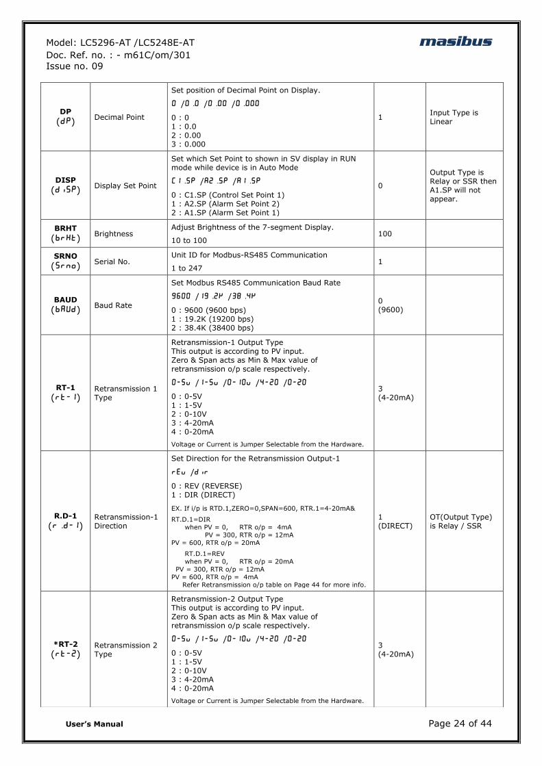
DP
(dp) Decimal Point
Set position of Decimal Point on Display.
0 /0.0 /0.00 /0.000
0 : 0 1 : 0.0 2 : 0.00 3 : 0.000
1 Input Type is Linear
DISP
(disp) Display Set Point
Set which Set Point to shown in SV display in RUN mode while device is in Auto Mode
C1.sp /A2.sp /A1.sp
0 : C1.SP (Control Set Point 1) 1 : A2.SP (Alarm Set Point 2) 2 : A1.SP (Alarm Set Point 1)
0
Output Type is Relay or SSR then A1.SP will not appear.
BRHT
(brHt) Brightness
Adjust Brightness of the 7-segment Display.
10 to 100 100
SRNO
(srno) Serial No.
Unit ID for Modbus-RS485 Communication
1 to 247 1
BAUD
(baud) Baud Rate
Set Modbus RS485 Communication Baud Rate
9600 /19.2k /38.4k
0 : 9600 (9600 bps) 1 : 19.2K (19200 bps) 2 : 38.4K (38400 bps)
0 (9600)
RT-1
(rt-1)
Retransmission 1 Type
Retransmission-1 Output Type This output is according to PV input. Zero & Span acts as Min & Max value of retransmission o/p scale respectively.
0-5v /1-5v /0-10v /4-20 /0-20
0 : 0-5V 1 : 1-5V 2 : 0-10V 3 : 4-20mA 4 : 0-20mA
Voltage or Current is Jumper Selectable from the Hardware.
3 (4-20mA)
R.D-1
(r.D-1)
Retransmission-1 Direction
Set Direction for the Retransmission Output-1
rev /dir
0 : REV (REVERSE) 1 : DIR (DIRECT)
EX. If i/p is RTD.1,ZERO=0,SPAN=600, RTR.1=4-20mA&
RT.D.1=DIR
when PV = 0, RTR o/p = 4mA
PV = 300, RTR o/p = 12mA
PV = 600, RTR o/p = 20mA
RT.D.1=REV
when PV = 0, RTR o/p = 20mA
PV = 300, RTR o/p = 12mA
PV = 600, RTR o/p = 4mA
Refer Retransmission o/p table on Page 44 for more info.
1 (DIRECT)
OT(Output Type) is Relay / SSR
*RT-2
(rt-2)
Retransmission 2 Type
Retransmission-2 Output Type This output is according to PV input. Zero & Span acts as Min & Max value of retransmission o/p scale respectively.
0-5v /1-5v /0-10v /4-20 /0-20
0 : 0-5V 1 : 1-5V 2 : 0-10V 3 : 4-20mA 4 : 0-20mA
Voltage or Current is Jumper Selectable from the Hardware.
3 (4-20mA)
Model: LC5296-AT /LC5248E-AT masibus Doc. Ref. no. : - m61C/om/301
Issue no. 09
User‟s Manual Page 25 of 44
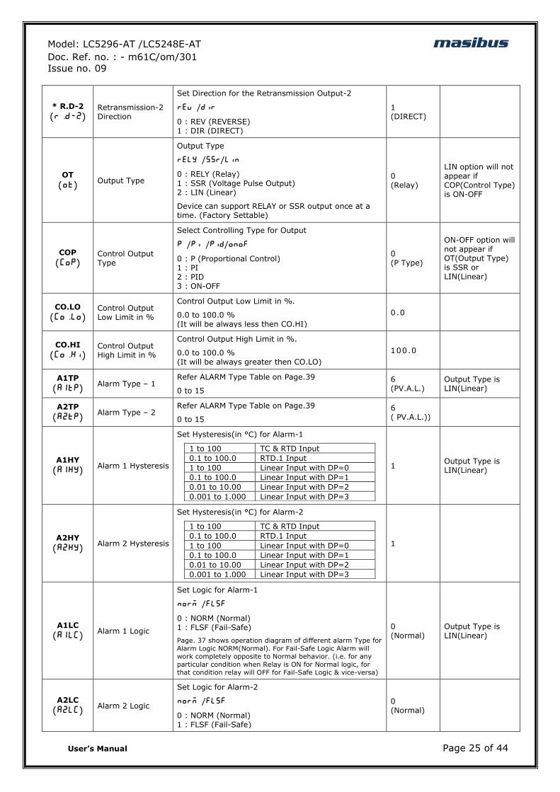
* R.D-2
(r.d-2)
Retransmission-2 Direction
Set Direction for the Retransmission Output-2
rev /dir
0 : REV (REVERSE) 1 : DIR (DIRECT)
1 (DIRECT)
OT
(ot) Output Type
Output Type
rely /ssr/lin
0 : RELY (Relay) 1 : SSR (Voltage Pulse Output) 2 : LIN (Linear)
Device can support RELAY or SSR output once at a time. (Factory Settable)
0 (Relay)
LIN option will not appear if COP(Control Type) is ON-OFF
COP
(Cop)
Control Output Type
Select Controlling Type for Output
P /Pi /pid/onof
0 : P (Proportional Control) 1 : PI 2 : PID 3 : ON-OFF
0 (P Type)
ON-OFF option will not appear if OT(Output Type) is SSR or LIN(Linear)
CO.LO
(Co.Lo)
Control Output Low Limit in %
Control Output Low Limit in %.
0.0 to 100.0 % (It will be always less then CO.HI)
0.0
CO.HI
(Co.Hi)
Control Output High Limit in %
Control Output High Limit in %.
0.0 to 100.0 % (It will be always greater then CO.LO)
100.0
A1TP
(a1tp) Alarm Type – 1
Refer ALARM Type Table on Page.39
0 to 15
6 (PV.A.L.)
Output Type is LIN(Linear)
A2TP
(a2tp) Alarm Type – 2
Refer ALARM Type Table on Page.39
0 to 15
6 ( PV.A.L.))
A1HY
(a1HY) Alarm 1 Hysteresis
Set Hysteresis(in °C) for Alarm-1
1 to 100 TC & RTD Input
0.1 to 100.0 RTD.1 Input
1 to 100 Linear Input with DP=0
0.1 to 100.0 Linear Input with DP=1
0.01 to 10.00 Linear Input with DP=2
0.001 to 1.000 Linear Input with DP=3
1 Output Type is LIN(Linear)
A2HY
(a2Hy) Alarm 2 Hysteresis
Set Hysteresis(in °C) for Alarm-2
1 to 100 TC & RTD Input
0.1 to 100.0 RTD.1 Input
1 to 100 Linear Input with DP=0
0.1 to 100.0 Linear Input with DP=1
0.01 to 10.00 Linear Input with DP=2
0.001 to 1.000 Linear Input with DP=3
1
A1LC
(a1lC) Alarm 1 Logic
Set Logic for Alarm-1
norm /flsf
0 : NORM (Normal) 1 : FLSF (Fail-Safe)
Page. 37 shows operation diagram of different alarm Type for
Alarm Logic NORM(Normal). For Fail-Safe Logic Alarm will work completely opposite to Normal behavior. (i.e. for any
particular condition when Relay is ON for Normal logic, for
that condition relay will OFF for Fail-Safe Logic & vice-versa)
0 (Normal)
Output Type is LIN(Linear)
A2LC
(a2lC) Alarm 2 Logic
Set Logic for Alarm-2
norm /flsf
0 : NORM (Normal) 1 : FLSF (Fail-Safe)
0 (Normal)
Model: LC5296-AT /LC5248E-AT masibus Doc. Ref. no. : - m61C/om/301
Issue no. 09
User‟s Manual Page 26 of 44
* Not applicable for LC5248E-AT
6.7 CALIBRATIONMODE
* Not applicable for LC5248E-AT
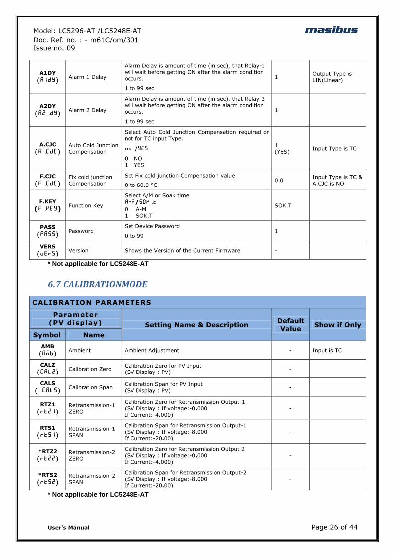
A1DY
(a1dy) Alarm 1 Delay
Alarm Delay is amount of time (in sec), that Relay-1 will wait before getting ON after the alarm condition occurs.
1 to 99 sec
1 Output Type is LIN(Linear)
A2DY
(a2.Dy) Alarm 2 Delay
Alarm Delay is amount of time (in sec), that Relay-2 will wait before getting ON after the alarm condition occurs.
1 to 99 sec
1
A.CJC
(a.CJC)
Auto Cold Junction Compensation
Select Auto Cold Junction Compensation required or not for TC input Type.
no /yes
0 : NO
1 : YES
1 (YES)
Input Type is TC
F.CJC
(F.CJC)
Fix cold junction Compensation
Set Fix cold junction Compensation value.
0 to 60.0 °C 0.0
Input Type is TC & A.CJC is NO
F.KEY
(F.KEY) Function Key
Select A/M or Soak time
A-M/SOK.T 0 : A-M 1 : SOK.T
SOK.T
PASS
(pass) Password
Set Device Password
0 to 99 1
VERS
(vers) Version Shows the Version of the Current Firmware -
CALIBRATION PARAMETERS
Parameter
(PV display) Setting Name & Description Default
Value Show if Only
Symbol Name
AMB
(Amb) Ambient Ambient Adjustment - Input is TC
CALZ
(Calz) Calibration Zero
Calibration Zero for PV Input (SV Display : PV)
-
CALS
(\Cals) Calibration Span
Calibration Span for PV Input (SV Display : PV)
-
RTZ1
(rtz1)
Retransmission-1 ZERO
Calibration Zero for Retransmission Output-1 (SV Display : If voltage:-0.000 If Current:-4.000)
-
RTS1
(rts1)
Retransmission-1 SPAN
Calibration Span for Retransmission Output-1 (SV Display : If voltage:-8.000 If Current:-20.00)
-
*RTZ2
(rtz2)
Retransmission-2 ZERO
Calibration Zero for Retransmission Output 2 (SV Display : If voltage:-0.000 If Current:-4.000)
-
*RTS2
(rts2)
Retransmission-2 SPAN
Calibration Span for Retransmission Output-2 (SV Display : If voltage:-8.000 If Current:-20.00)
-
Model: LC5296-AT /LC5248E-AT masibus Doc. Ref. no. : - m61C/om/301
Issue no. 09
User‟s Manual Page 27 of 44
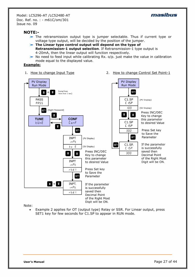
NOTE:- The retransmission output type is jumper selectable. Thus if current type or
voltage type output, will be decided by the position of the jumper.
The Linear type control output will depend on the type of
Retransmission-1 output selection. If Retransmission-1 type output is
4-20mA, then the linear output will function respectively.
No need to feed input while calibrating Rx. o/p. just make the value in calibration
mode equal to the displayed value.
Example:
1. How to change Input Type 2. How to change Control Set Point-1
Note:
Example 2 applies for OT (output type) Relay or SSR. For Linear output, press
SET1 key for few seconds for C1.SP to appear in RUN mode.
Model: LC5296-AT /LC5248E-AT masibus Doc. Ref. no. : - m61C/om/301
Issue no. 09
User‟s Manual Page 28 of 44
7. CONTROL FUNCTION
7.1 ON/OFF Control
ON/OFF Controller is the simplest form of temperature control device. The output from
the device is either on or off, with no middle state. An on-off controller will switch the
output only when the temperature crosses the setpoint. For heating control, the output
is on when the temperature is below the set point, and off above set point.
Since the temperature crosses the set point to change the output stage, the process
temperature will be cycling continually, going from below set point to above, and back
below. In cases where this cycling occurs rapidly, and to prevent contactors and valves
from getting damaged, an on-off differential, or “hysteresis,” is added to the controller
operations. On-Off hysteresis prevents the output from “chattering” or making fast,
continual switches if the cycling above and below the set point occurs very rapidly.
Figure 7.1: Typical Relay operation
High type (H-ON):
For High type of set value, once process value reaches up to set point + Hysteresis
value, relay will be ON after few seconds (as per relay delay) and it will be ON until
process value goes down to Set point.
Low type (L-ON):
For Low type of set value, once process value reaches down to set point – Hysteresis
value relay will be ON after nearly few seconds (as per relay delay) and it will be ON
until process value goes up toward Set point.
NOTE:-
LC5296-AT/LC5248E-AT has both ON-OFF & PID Controlling for Relay-1.
And Relay-2 is used for Alarm output. If ON-OFF controlling is required
for Relay-1, COP (Control Type) must be selected as ON-OFF.
When PB,TI,TD term is „0‟ and auto tune is set „no‟, and unit is not in
manual mode, then control output will work as on-off controller else it
will work as PID controller.
Model: LC5296-AT /LC5248E-AT masibus Doc. Ref. no. : - m61C/om/301
Issue no. 09
User‟s Manual Page 29 of 44
7.2 PID Control
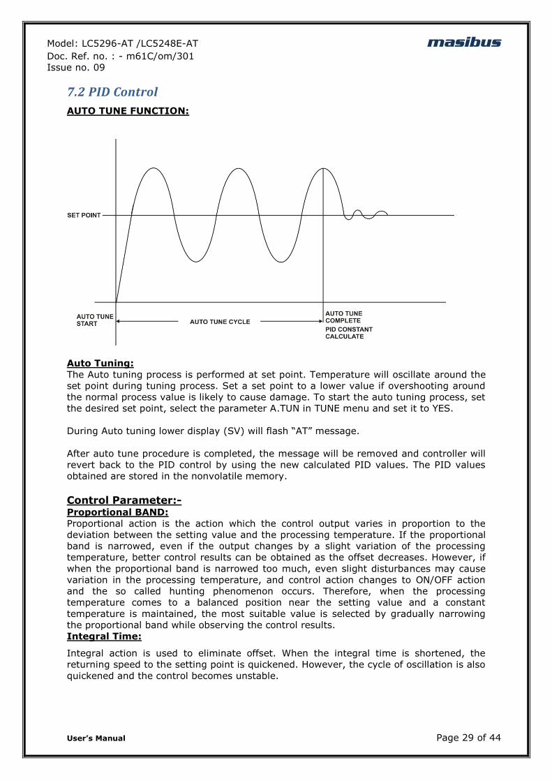
AUTO TUNE FUNCTION:
Auto Tuning:
The Auto tuning process is performed at set point. Temperature will oscillate around the
set point during tuning process. Set a set point to a lower value if overshooting around
the normal process value is likely to cause damage. To start the auto tuning process, set
the desired set point, select the parameter A.TUN in TUNE menu and set it to YES.
During Auto tuning lower display (SV) will flash “AT” message.
After auto tune procedure is completed, the message will be removed and controller will
revert back to the PID control by using the new calculated PID values. The PID values
obtained are stored in the nonvolatile memory.
Control Parameter:-
Proportional BAND:
Proportional action is the action which the control output varies in proportion to the
deviation between the setting value and the processing temperature. If the proportional
band is narrowed, even if the output changes by a slight variation of the processing
temperature, better control results can be obtained as the offset decreases. However, if
when the proportional band is narrowed too much, even slight disturbances may cause
variation in the processing temperature, and control action changes to ON/OFF action
and the so called hunting phenomenon occurs. Therefore, when the processing
temperature comes to a balanced position near the setting value and a constant
temperature is maintained, the most suitable value is selected by gradually narrowing
the proportional band while observing the control results.
Integral Time:
Integral action is used to eliminate offset. When the integral time is shortened, the
returning speed to the setting point is quickened. However, the cycle of oscillation is also
quickened and the control becomes unstable.
Model: LC5296-AT /LC5248E-AT masibus Doc. Ref. no. : - m61C/om/301
Issue no. 09
User‟s Manual Page 30 of 44
Derivative Time:
Derivative action is used to restore the change in the processing temperature according
to the rate of change. It reduces the amplitude of overshoot and undershoots width. If
the derivative time is shortened, restoring value becomes small, and if the derivative
time is made longer, an excessive returning phenomenon may occur and the control
system may be oscillated.
Manual Reset:
Virtually no process requires precisely 50% output on single output controls or 0%
output on two output controls. Because of this many older control designs incorporated
an adjustment called manual reset (also called offset on some controls). This adjustment
allows the user to redefine the output requirement at the set point. A proportioning
control without manual reset or Integral time (defined above) will settle out somewhere
within the proportioning band but likely not on the set point.
Some controls use manual reset (as a digital user programmable value), this allows the
user to preprogram the approximate output requirement at the set point to allow for
quicker settling at set point when Automatic reset (Integral time) set to zero. Range for
the manual reset is -50.0% to +50.0% of proportional band for LC5296-AT.
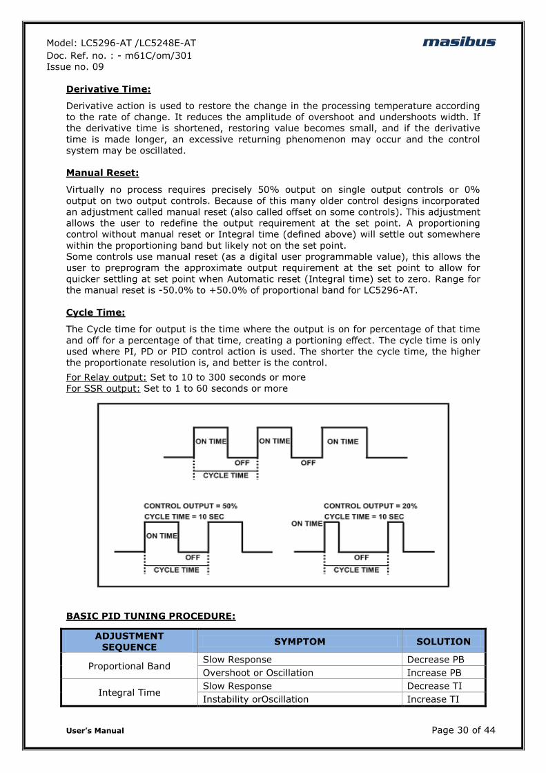
Cycle Time:
The Cycle time for output is the time where the output is on for percentage of that time
and off for a percentage of that time, creating a portioning effect. The cycle time is only
used where PI, PD or PID control action is used. The shorter the cycle time, the higher
the proportionate resolution is, and better is the control.
For Relay output: Set to 10 to 300 seconds or more
For SSR output: Set to 1 to 60 seconds or more
BASIC PID TUNING PROCEDURE:
ADJUSTMENT
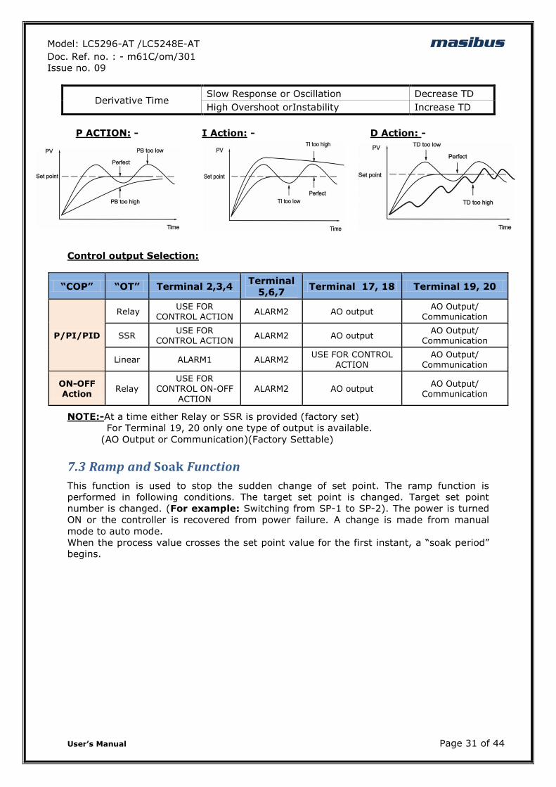
SEQUENCE SYMPTOM SOLUTION
Proportional Band Slow Response Decrease PB
Overshoot or Oscillation Increase PB
Integral Time Slow Response Decrease TI
Instability orOscillation Increase TI
Model: LC5296-AT /LC5248E-AT masibus Doc. Ref. no. : - m61C/om/301
Issue no. 09
User‟s Manual Page 31 of 44
Derivative Time Slow Response or Oscillation Decrease TD
High Overshoot orInstability Increase TD
P ACTION: - I Action: - D Action: -
Control output Selection:
“COP” “OT” Terminal 2,3,4 Terminal
5,6,7 Terminal 17, 18 Terminal 19, 20
P/PI/PID
Relay USE FOR
CONTROL ACTION ALARM2 AO output
AO Output/ Communication
SSR USE FOR
CONTROL ACTION ALARM2 AO output
AO Output/ Communication
Linear ALARM1 ALARM2 USE FOR CONTROL
ACTION
AO Output/
Communication
ON-OFF Action
Relay USE FOR
CONTROL ON-OFF ACTION
ALARM2 AO output AO Output/
Communication
NOTE:-At a time either Relay or SSR is provided (factory set)
For Terminal 19, 20 only one type of output is available.
(AO Output or Communication)(Factory Settable)
7.3 Ramp and Soak Function
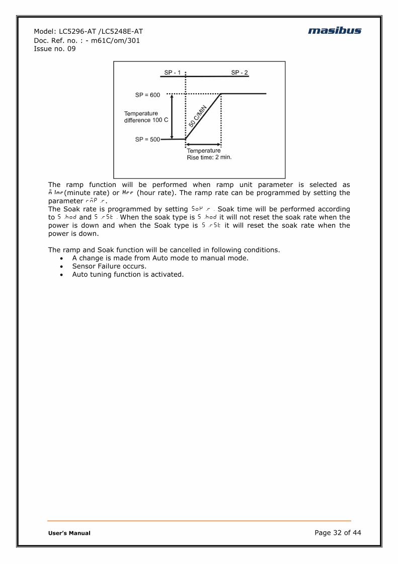
This function is used to stop the sudden change of set point. The ramp function is
performed in following conditions. The target set point is changed. Target set point
number is changed. (For example: Switching from SP-1 to SP-2). The power is turned
ON or the controller is recovered from power failure. A change is made from manual
mode to auto mode.
When the process value crosses the set point value for the first instant, a “soak period”
begins.
Model: LC5296-AT /LC5248E-AT masibus Doc. Ref. no. : - m61C/om/301
Issue no. 09
User‟s Manual Page 32 of 44
The ramp function will be performed when ramp unit parameter is selected as MInR(minute rate) or HRR (hour rate). The ramp rate can be programmed by setting the
parameter rmp.r.
The Soak rate is programmed by setting sok.r. Soak time will be performed according
to s.hod and s.rst. When the soak type is s.hod it will not reset the soak rate when the
power is down and when the Soak type is s.rst it will reset the soak rate when the
power is down.
The ramp and Soak function will be cancelled in following conditions.
A change is made from Auto mode to manual mode.
Sensor Failure occurs.
Auto tuning function is activated.
Model: LC5296-AT /LC5248E-AT masibus Doc. Ref. no. : - m61C/om/301
Issue no. 09
User‟s Manual Page 33 of 44
8. ALARM OUTPUT
For all Alarm outputs there are five settings. (As shown in configuration mode Menu)
Set Value (in run mode)
Type
Hysteresis(Dead band)
Direction (Normal/Fail safe)
Delay
SET VALUE: Alarm set point
8.1 ALARM TYPES
Various alarm operations are shown in the reference figure.
ALARM
TYPE
NO
Display
message
ALARM TYPE Note
0 none None NO operation available
1 Pv.d.H Deviation High alarm Ref figure 3
2 Pv.d.l Deviation Low alarm Ref figure 4
3 Pv.d.r Deviation High & Low range alarm Ref figure 5
4 Pv.d.b Deviation High & Low Band alarm Ref figure 6
5 Pv.a.H Absolute value High alarm Ref figure 1
6 Pv.A.L Absolute value Low alarm Ref figure 2
7 SP.A.H Absolute value set point high alarm Ref figure 7
8 SP.A.L Absolute value set point low alarm Ref figure 8
9 P.S.d.H Deviation High alarm with standby Same as figure 3
10 P.S.d.L Deviation Low alarm with standby Same as figure 4
11 P.S.d.r Deviation High & Low range alarm with standby Same as figure 5
12 P.S.d.b Deviation High & Low limit alarm with standby Same as figure 6
13 P.S.A.H Absolute value High alarm with standby Same as figure 1
14 P.S.A.L Absolute value Low alarm with standby Same as figure 2
15 PV.-E. PV error(OPEN/OVER/UNDER) Note 1
NOTE-1:
The fault diagnosis output turns on in case of input burnout (PV) failure.
Model: LC5296-AT /LC5248E-AT masibus Doc. Ref. no. : - m61C/om/301
Issue no. 09
User‟s Manual Page 34 of 44
NOTE:-
LIT = LED on, UNLIT = LED off
Up arrow indicate Alarm will ON from this value.
Down arrow indicate Alarm will OFF from this value.
Model: LC5296-AT /LC5248E-AT masibus Doc. Ref. no. : - m61C/om/301
Issue no. 09
User‟s Manual Page 35 of 44
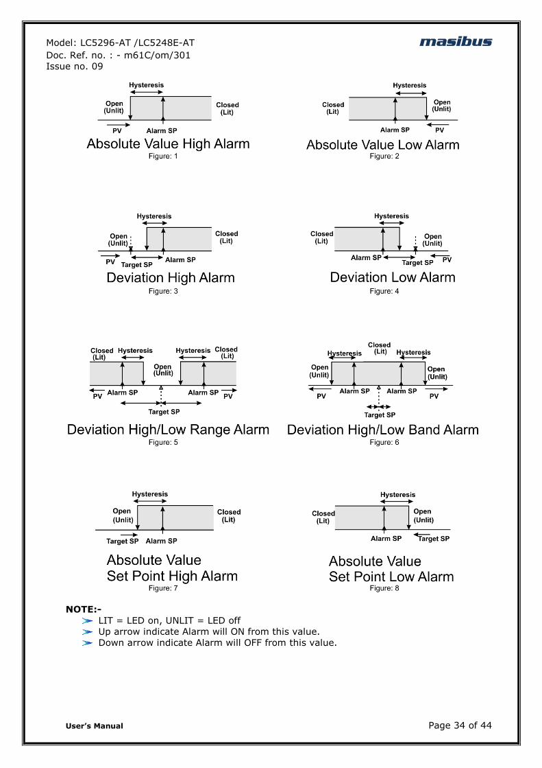
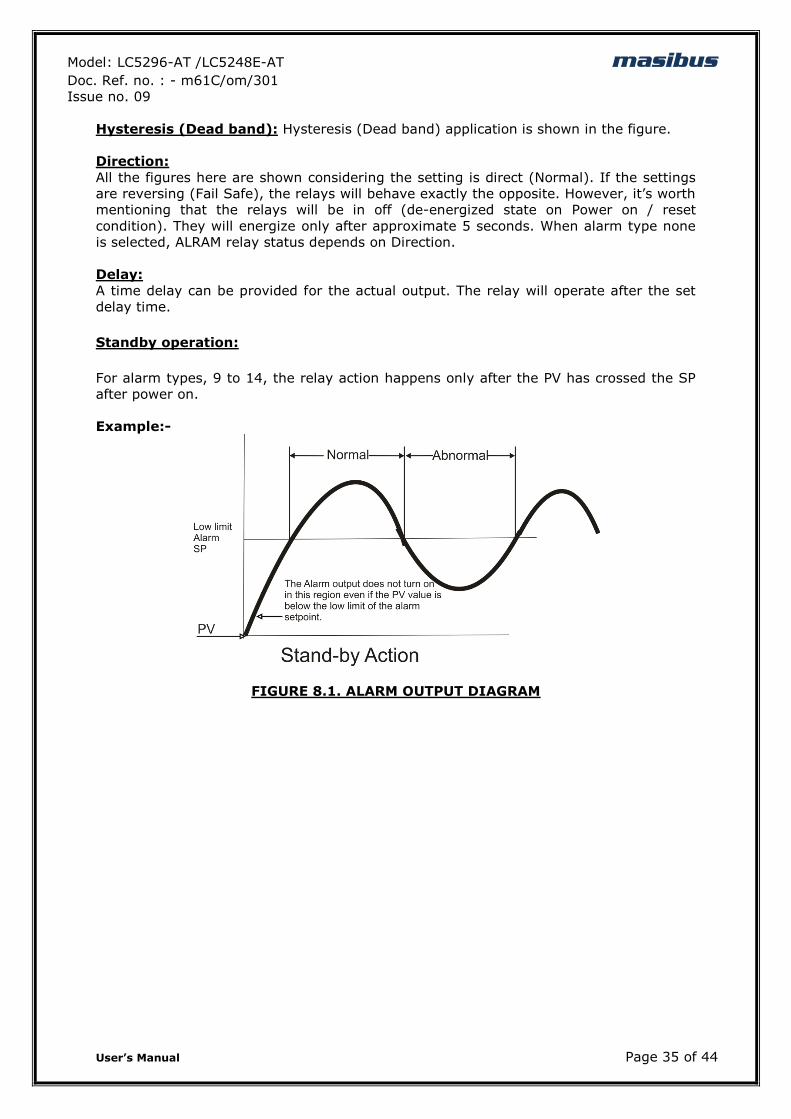
Hysteresis (Dead band): Hysteresis (Dead band) application is shown in the figure.
Direction:
All the figures here are shown considering the setting is direct (Normal). If the settings
are reversing (Fail Safe), the relays will behave exactly the opposite. However, it‟s worth
mentioning that the relays will be in off (de-energized state on Power on / reset
condition). They will energize only after approximate 5 seconds. When alarm type none
is selected, ALRAM relay status depends on Direction.
Delay:
A time delay can be provided for the actual output. The relay will operate after the set
delay time.
Standby operation:
For alarm types, 9 to 14, the relay action happens only after the PV has crossed the SP
after power on.
Example:-
FIGURE 8.1. ALARM OUTPUT DIAGRAM
Model: LC5296-AT /LC5248E-AT masibus Doc. Ref. no. : - m61C/om/301
Issue no. 09
User‟s Manual Page 36 of 44
9. CALIBRATION PROCEDURE
9.1 Procedure for CAL-zero and CAL-span
The instrument is factory calibrated for the specified range, but due to long term drift of
components, re-calibration may be necessary in some cases. For calibrating the
instrument a reliable source is required. This source should be at least ten times
accurate compared to the range of the instrument.
The unit can be calibrated without opening it and without trim pots.
For Entering into the Calibration Mode, Please refer Menu Layout.
After applying appropriate Input from the calibrator source, press „INCREMENT‟ OR
„DECREMENT KEY‟ to bring the actual process value on display.
Example:-
At zero calibration reading expected on the display is 100 and it shows 107, adjust the
process value to 100 by using „DECREMENT KEY‟. Now press „SET‟ to store the calibration
parameter in non-volatile memory. Similarly one can calibrate Ambient, SPAN and
retransmission parameters.
For calibrating i/p, both zero and span are calibrated. Here one-shot calibration
technique is used, i.e. the zero and span are calibrated once. Individual zero or span can
also be calibrated; first calibrate zero and then span. While calibrating thermocouple
type input, first calibrate the ambient (if required) and then continue with the span
calibration of the same.
9.2 Procedure for RET-zero and RET-span
For calibrating the retransmission output, both retransmission zero and retransmission
span has to be calibrated. At a time there can be either one or two retransmission output
available. If only one retransmission is used, then calibrate RTZ1 (retransmission 1
zero) and RTS1 (retransmission 1 span)and if there are two retransmission outputs
available, then calibrate RTZ2 (retransmission 2 zero)and RTS2 (retransmission 2 span)
for second retransmission. No need to feed input while calibrating retransmission o/p.it
is like calibrating using digital trim pot. Only look at the output, display value has no
significance with output generated.
Example:-
At retransmission zero calibration, expected output is 4.00mA and it gives 4.153mA.
Then adjust the output value to 4.153 by using „INCREMENT KEY‟. Now press „SET1‟ to
store the calibration parameter in non-volatile memory. Similarly one can calibrate
retransmission span.
Model: LC5296-AT /LC5248E-AT masibus Doc. Ref. no. : - m61C/om/301
Issue no. 09
User‟s Manual Page 37 of 44
10. COMMUNICATION PROTOCOL–MODBUS RTU
10.1 Introduction
The unit can be connected in RS-485 communication data link either in multi drop or
repeat mode. Each unit must have unique Serial Number. Entire range of addresses (1 to
247) may be used. Before starting any communication, choose a baud rate compatible to
the host computer. The serial protocol used is MODBUS RTU.
Function Code for Modbus
CODE NAME Function
01 Read coil status Use to read Relay and Digital output status
03 Read Holding registers Use to read PV, Control, RSP output etc
04 Read input registers Use to read programmable registers
06 Preset Single register Use to write programmable register
The error checking field contains a 16-bit value implemented as two eight-bit bytes. The
error check value is the result of a Cyclical Redundancy Check (CRC) calculation
performed on the message contents.
10.2 Parameter Address Details
Sr.
No. Parameters Absolute
Address Type Access Type
1 PROCESS VALUE 30001 Int Read Only
2 POWER IN PERCENTAGE 30002 Int Read Only
3 AUTOTUNE STATUS 30003 Int Read Only
4 AMBIENT 30004 Int Read Only
5 SSR STATUS 30005 Int Read Only
6 RELAY-1 STATUS 30006 Int Read Only
7 RELAY-2 STATUS 30007 Int Read Only
NOTE:Process Value (PV) Error Conditions Value
OPEN : 32767
UNDER : 32765
OVER : 32766
Sr.
No. Parameters
Absolute
Address Type
Access
Type
1 Input Type 40001 Int R + W
2 Zero 40002 Int R + W
3 Span 40003 Int R + W
4 Filter 40004 Int R + W
5 SET Type-1 40005 Int R + W
6 Open Sensor Status 40006 Int R + W
7 Relay Delay -1 40007 Int R + W
Model: LC5296-AT /LC5248E-AT masibus Doc. Ref. no. : - m61C/om/301
Issue no. 09
User‟s Manual Page 38 of 44
8 Hysteresis 1 40008 Int R + W
9 Decimal Point 40009 Int R + W
10 Display set point 40010 Int R + W
11 Brightness 40011 Int R + W
12 Serial Number 40012 Int R + W
13 Baud Rate 40013 Int R + W
14 Retransmission o/p Type -1 40014 Int R + W
15 Retransmission o/p direction – 1 40015 Int R + W
16 Retransmission o/p Type -2 40016 Int R + W
17 Retransmission o/p direction – 2 40017 Int R + W
18 Control output type 40018 Int R + W
19 Control type 40019 Int R + W
20 Set Value 1 40020 Int R + W
21 Set Value 2 40021 Int R + W
22 Alarm-1 Type 40022 Int R + W
23 Alarm- 2 Type 40023 Int R + W
24 Alarm-1 hysteresis 40024 Int R + W
25 Alarm-2 hysteresis 40025 Int R + W
26 Alarm-1 logic 40026 Int R + W
27 Alarm-2 logic 40027 Int R + W
28 Alarm-1 delay 40028 Int R + W
29 Alarm-2 delay 40029 Int R + W
30 Auto CJC 40030 Int R + W
31 Fixed CJC 40031 Int R + W
32 Pass word 40032 Int R + W
33 Version 40033 Int R
34 Proportional band 40034 Int R + W
35 Integral time 40035 Int R + W
36 Derivative time 40036 Int R + W
37 Cycle time 40037 Int R + W
38 Manual reset 40038 Int R + W
39 Sampling rate 40039 Int R + W
40 Sampling period 40040 Int R + W
41 Control set point 40041 Int R + W
42 Control Output Low Limit 40042 Int R + W
43 Control Output High Limit 40043 Int R + W
44 Auto/Manual 40044 Int R + W
45 % POWER 40045 Int R + W
46 Ramp – type 40046 Int R + W
47 Ramp – rate 40047 Int R + W
48 Soak - rate 40048 Int R + W
49 Soak type 40049 Int R + W
50 offset 40050 Int R + W
51 Function Key 40051 Int R + W
Model: LC5296-AT /LC5248E-AT masibus Doc. Ref. no. : - m61C/om/301
Issue no. 09
User‟s Manual Page 39 of 44
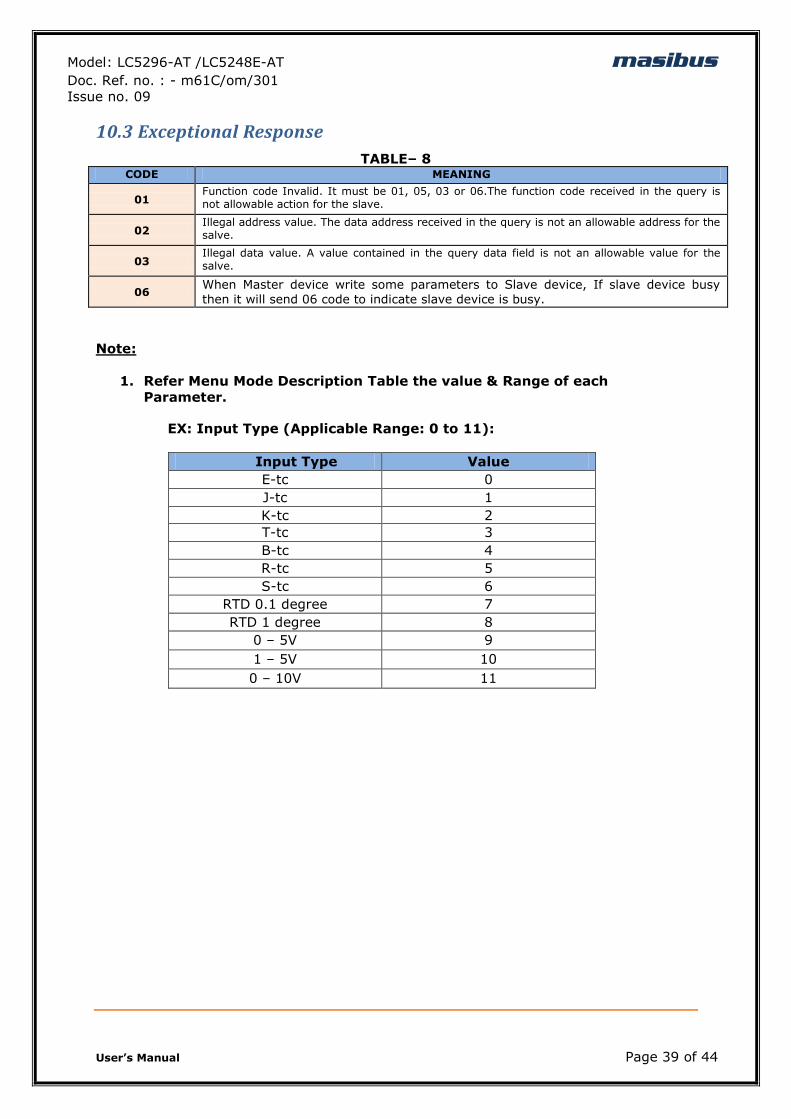
10.3 Exceptional Response
TABLE– 8 CODE MEANING
01 Function code Invalid. It must be 01, 05, 03 or 06.The function code received in the query is not allowable action for the slave.
02 Illegal address value. The data address received in the query is not an allowable address for the salve.
03 Illegal data value. A value contained in the query data field is not an allowable value for the salve.
06 When Master device write some parameters to Slave device, If slave device busy
then it will send 06 code to indicate slave device is busy.
Note:
1. Refer Menu Mode Description Table the value & Range of each
Parameter.
EX: Input Type (Applicable Range: 0 to 11):
Input Type Value
E-tc 0
J-tc 1
K-tc 2
T-tc 3
B-tc 4
R-tc 5
S-tc 6
RTD 0.1 degree 7
RTD 1 degree 8
0 – 5V 9
1 – 5V 10
0 – 10V 11
Model: LC5296-AT /LC5248E-AT masibus Doc. Ref. no. : - m61C/om/301
Issue no. 09
User‟s Manual Page 40 of 44
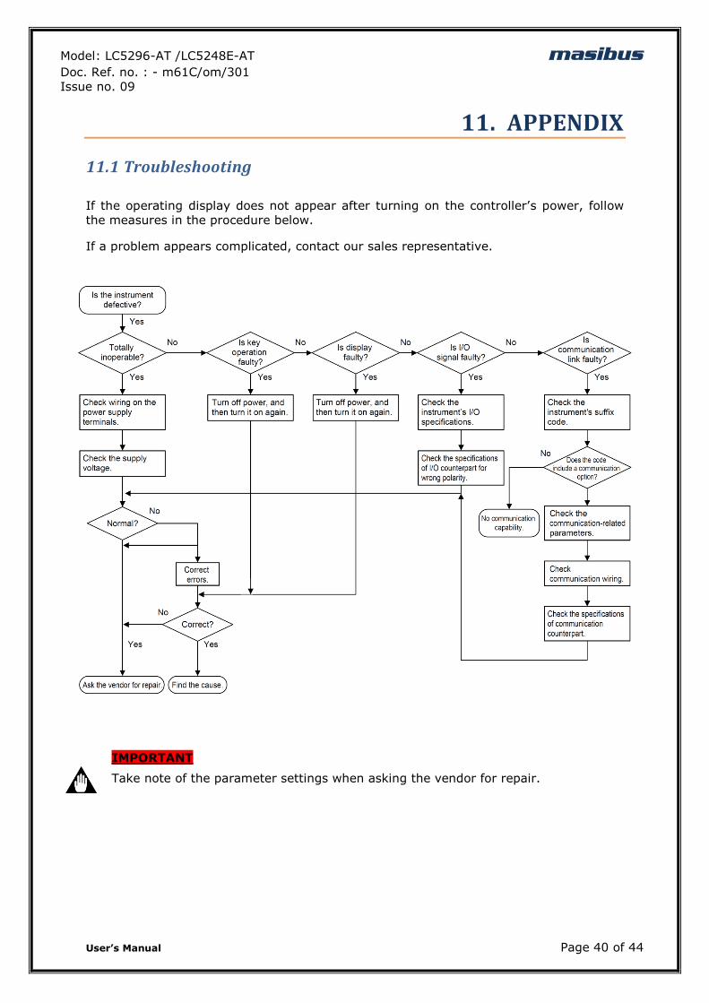
11. APPENDIX
11.1 Troubleshooting
If the operating display does not appear after turning on the controller‟s power, follow
the measures in the procedure below.
If a problem appears complicated, contact our sales representative.
IMPORTANT
Take note of the parameter settings when asking the vendor for repair.
Model: LC5296-AT /LC5248E-AT masibus Doc. Ref. no. : - m61C/om/301
Issue no. 09
User‟s Manual Page 41 of 44
11.2 ON-OFF LOGIC
Relay type PV Relay LED
Hi-On PV > SP On On
PV < SP Off Off
Open sensor Up scale On On
Down scale Off Off
Low-On PV > SP Off Off
PV < SP On On
Open sensor Up scale Off Off
Down scale On On
11.3 Retransmission Output Table for OPEN /OVER /UNDER Condition
RETRASMISSION VARIABLE SCALE ACTION OPEN OVER UNDER
4-20mA PV UP DIR 20.8 20.8 3.2
PV DOWN REV 3.2 3.2 20.8
PV UP REV 20.8 3.2 20.8
PV DOWN DIR 3.2 20.8 3.2
1-5V PV UP DIR 5.2V 5.2V 0.8V
PV DOWN REV 0.8V 0.8V 5.2V
PV UP REV 5.2V 0.8V 5.2V
PV DOWN DIR 0.8V 5.2V 0.8V
NOTE: -
1. OPEN/UNDER/OVER condition is applicable to all input types except 0-5v /
0-20mA.
11.4 Linear Output Table for OPEN/OVER/ UNDER Condition
CONTROL OP Process
Scale
Output Direction (O.DIR)
DISPLAY INDICATION
OPEN OVER UNDER
4-20mamp UP DIR 20.0 20.0 4.0
Current
DOWN REV 4.0 4.0 20.0
UP REV 20.0 4.0 20.0
DOWN DIR 4.0 20.0 4.0
SSR UP DIR ON ON OFF
Model: LC5296-AT /LC5248E-AT masibus Doc. Ref. no. : - m61C/om/301
Issue no. 09
User‟s Manual Page 42 of 44
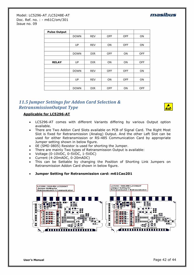
Pulse Output
DOWN REV OFF OFF ON
UP REV ON OFF ON
DOWN DIR OFF ON OFF
RELAY UP DIR ON ON OFF
DOWN REV OFF OFF ON
UP REV ON OFF ON
DOWN DIR OFF ON OFF
11.5 Jumper Settings for Addon Card Selection & RetransmissionOutput Type
Applicable for LC5296-AT
LC5296-AT comes with different Variants differing by various Output option
available.
There are Two Addon Card Slots available on PCB of Signal Card. The Right Most
Slot is fixed for Retransmission (Analog) Output. And the other Left Slot can be
used for either Retransmission or RS-485 Communication Card by appropriate
Jumper setting shown in below figure.
0E (SMD 0805) Resistor is used for shorting the Jumper.
There are mainly Two types of Retransmission Output is available:
Voltage (0-10VDC, 0-5VDC, 1-5VDC)
Current (4-20mADC, 0-20mADC)
This can be Settable by changing the Position of Shorting Link Jumpers on
Retransmission Addon Card shown in below figure.
Jumper Setting for Retransmission card: m61Cao201
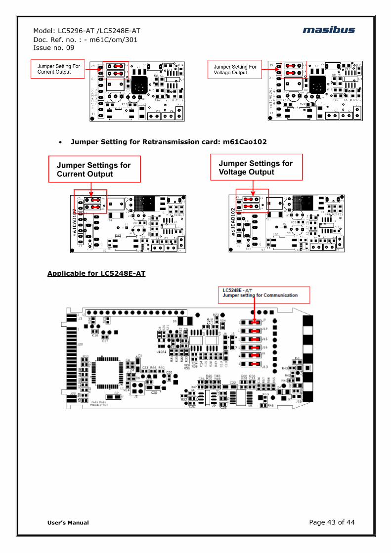
Model: LC5296-AT /LC5248E-AT masibus Doc. Ref. no. : - m61C/om/301
Issue no. 09
User‟s Manual Page 43 of 44
Jumper Setting for Retransmission card: m61Cao102
Applicable for LC5248E-AT
Model: LC5296-AT /LC5248E-AT masibus Doc. Ref. no. : - m61C/om/301
Issue no. 09
User‟s Manual Page 44 of 44
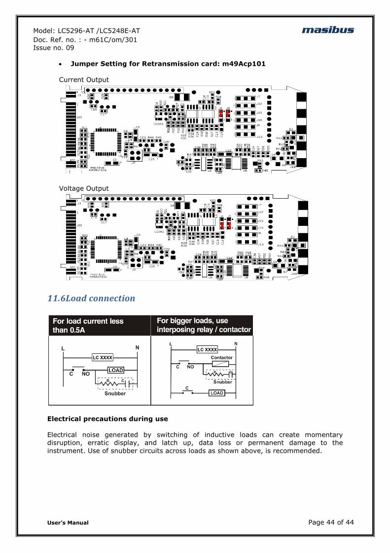
Jumper Setting for Retransmission card: m49Acp101
Current Output
Voltage Output
11.6Load connection
Electrical precautions during use
Electrical noise generated by switching of inductive loads can create momentary
disruption, erratic display, and latch up, data loss or permanent damage to the
instrument. Use of snubber circuits across loads as shown above, is recommended.