Embed Size (px)
Citation preview
SSL UC1
www.solidstatelogic.com
SSL UC1User Guide

Visit SSL at:
www.solidstatelogic.com
© Solid State Logic
All rights reserved under International and Pan-American Copyright Conventions.
SSL® and Solid State Logic® are registered trademarks of Solid State Logic.
SSL UC1™ is a trademark of Solid State Logic.
All other product names and trademarks are the property of their respective owners and are hereby acknowledged.
Pro Tools® is a registered trademark of Avid®.
Logic Pro® and Logic® are registered trademarks of Apple® Inc.
Studio One® is a registered trademark of Presonus® Audio Electronics Inc.
Cubase® and Nuendo® are trademarks of Steinberg® Media Technologies GmbH.
REAPER® is a trademark of Cockos Incorporated.
No part of this publication may be reproduced in any form or by any means, whether mechanical or electronic, without the
written permission of Solid State Logic, Begbroke, OX5 1RU, England.
As research and development is a continual process, Solid State Logic reserves the right to change the features and
specifications described herein without notice or obligation.
Solid State Logic cannot be held responsible for any loss or damage arising directly or indirectly from any error or omission in
this manual.
PLEASE READ ALL INSTRUCTIONS, PAY SPECIAL HEED TO SAFETY WARNINGS.
E&OE
Revision 1.3 - May 2021
Contents
SSL UC1 User Guide
Table of ContentsOverview 5
What is SSL UC1? 5
Features 5
Supported DAWs - For UC1 & The Plug-in Mixer 5
5 Things About UC1 6Get-Started 7
Unpacking 7
Fitting The Stands (Optional) 7
Additional Elevation Angles 7Dimensions 8Weight 8
Connecting Your UC1 Hardware 8
USB Cables 8Downloading SSL 360° & SSL Native Channel Strip 2 and Bus Compressor 2 Plug-ins 9
Installing SSL 360° Software 9
Installing SSL Native Channel Strip 2 and Bus Compressor 2 Plug-ins 10
Screen Resolution Requirements 10
General System Requirements 10
Redeeming and Authorising Your Plug-in Licences 11
UC1 14Front Panel 14
Smart LED Rings 15The Virtual Notch 15The Channel Strip and Bus Compressor IN Buttons 15Channel Strip 2 Dynamics Metering 15Bus Compressor Meter 16SOLO and CUT Buttons 16FINE Button 16
Central Control Panel 17
Process Order Routing 18Presets 18
Channel Strip 2 20Filter Section 21EQ Section 21Dynamics Section 22Bypass, Metering and Trims 23Dynamics Sidechain Options 23Plug-in Mixer Number, Track Name and Plug-in Mixer Button 23Version Number, Misc Functions, SOLO and CUT 23How the SOLO system works 24Process Ordering 25Undo/Redo and A/B 25Presets Location 25
Contents
SSL UC1 User Guide
Bus Compressor 2 26Bus Compressor Controls 26Gain Reduction Meter 27Oversampling 27DAW Track Name and Plug-in Mixer Button 27External S/C and Mix Lock 27Undo/Redo and A/B 27Version Number 28Presets Location 28
SSL 360° Software 29Home Page 29
Plug-in Mixer 31
Left-hand Toolbar Menu 31Plug-in Mixer - Zoomed Out View 33Plug-in Mixer - Zoomed In View 33Adding/Removing Channel Strips to the Plug-in Mixer 34Channel Strip 2 Ordering in the Plug-in Mixer 34Logic Pro 10.6.1 and above - Aux Tracks 35Logic Pro 10.6.0 and below - Disable Dynamic Plug-in Loading 35Adding/Removing Bus Compressors to the Plug-in Mixer 36Selecting a Channel Strip 36Selecting a Bus Compressor 36
Restrictions and Important Notes 37Multi-Mono Plug-ins in the Plug-in Mixer 37'Save As Default' For Channel Strip 2 and Bus Compressor 2 Plug-ins 37Not Supported - Mixing VSTs and AUs 37
UC1 LCD Messages 38SSL 360° Software Messages 39SSL Support - FAQs, Ask a Question and Compatibility 40Safety Notices 41
Overview
5SSL UC1 User Guide
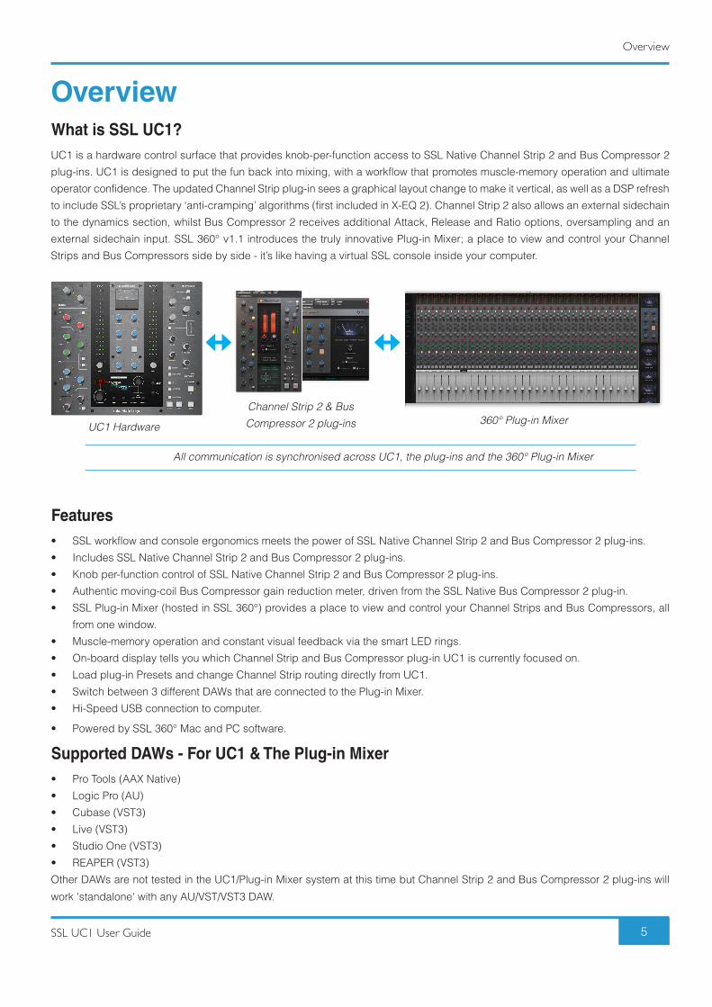
OverviewWhat is SSL UC1?UC1 is a hardware control surface that provides knob-per-function access to SSL Native Channel Strip 2 and Bus Compressor 2
plug-ins. UC1 is designed to put the fun back into mixing, with a workflow that promotes muscle-memory operation and ultimate
operator confidence. The updated Channel Strip plug-in sees a graphical layout change to make it vertical, as well as a DSP refresh
to include SSL’s proprietary ‘anti-cramping’ algorithms (first included in X-EQ 2). Channel Strip 2 also allows an external sidechain
to the dynamics section, whilst Bus Compressor 2 receives additional Attack, Release and Ratio options, oversampling and an
external sidechain input. SSL 360° v1.1 introduces the truly innovative Plug-in Mixer; a place to view and control your Channel
Strips and Bus Compressors side by side - it’s like having a virtual SSL console inside your computer.
All communication is synchronised across UC1, the plug-ins and the 360° Plug-in Mixer
Features• SSL workflow and console ergonomics meets the power of SSL Native Channel Strip 2 and Bus Compressor 2 plug-ins.
• Includes SSL Native Channel Strip 2 and Bus Compressor 2 plug-ins.
• Knob per-function control of SSL Native Channel Strip 2 and Bus Compressor 2 plug-ins.
• Authentic moving-coil Bus Compressor gain reduction meter, driven from the SSL Native Bus Compressor 2 plug-in.
• SSL Plug-in Mixer (hosted in SSL 360°) provides a place to view and control your Channel Strips and Bus Compressors, all
from one window.
• Muscle-memory operation and constant visual feedback via the smart LED rings.
• On-board display tells you which Channel Strip and Bus Compressor plug-in UC1 is currently focused on.
• Load plug-in Presets and change Channel Strip routing directly from UC1.
• Switch between 3 different DAWs that are connected to the Plug-in Mixer.
• Hi-Speed USB connection to computer.
• Powered by SSL 360° Mac and PC software.
Supported DAWs - For UC1 & The Plug-in Mixer• Pro Tools (AAX Native)
• Logic Pro (AU)
• Cubase (VST3)
• Live (VST3)
• Studio One (VST3)
• REAPER (VST3)
Other DAWs are not tested in the UC1/Plug-in Mixer system at this time but Channel Strip 2 and Bus Compressor 2 plug-ins will
work 'standalone' with any AU/VST/VST3 DAW.
UC1 Hardware360° Plug-in Mixer
Channel Strip 2 & Bus Compressor 2 plug-ins
Overview
6 SSL UC1 User Guide
5 Things About UC1UC1 follows you around – like a loyal dog or trusty sidekickOpening a Channel Strip 2 or Bus Compressor 2 plug-in GUI in the DAW automatically causes UC1 to focus on that plug-in.
You don’t have to look at the computer screen to use it. You can scroll through and select the Channel Strip 2 and Bus Compressor 2 plug-in you want to control and see the DAW track
name that the plug-in is inserted on, directly from UC1.
You can operate multiple controls at once Some plug-in controllers are restrictive because they limit you to turning one knob at a time, which isn’t very helpful when EQ'ing
a source. Thankfully, this is not the case with UC1 - grab two controls at once, no problem.
The Bus Compressor MeterThe Bus Compressor meter brings a new dimension to mixing with plug-ins by providing a truly analogue experience. The meter
is driven from the Bus Compressor 2 plug-in and allows you to allows keep an eye on your compression levels.
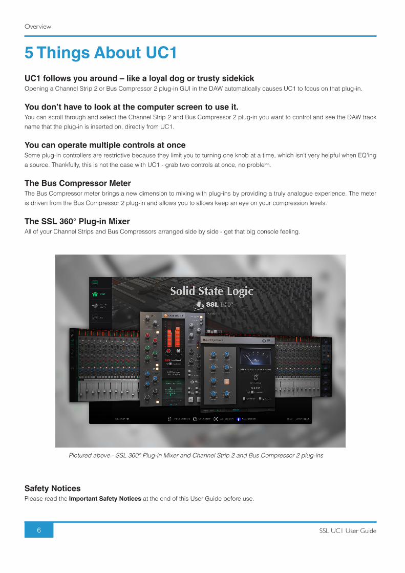
The SSL 360° Plug-in Mixer All of your Channel Strips and Bus Compressors arranged side by side - get that big console feeling.
Safety NoticesPlease read the Important Safety Notices at the end of this User Guide before use.
Pictured above - SSL 360° Plug-in Mixer and Channel Strip 2 and Bus Compressor 2 plug-ins
Get-Started
7SSL UC1 User Guide
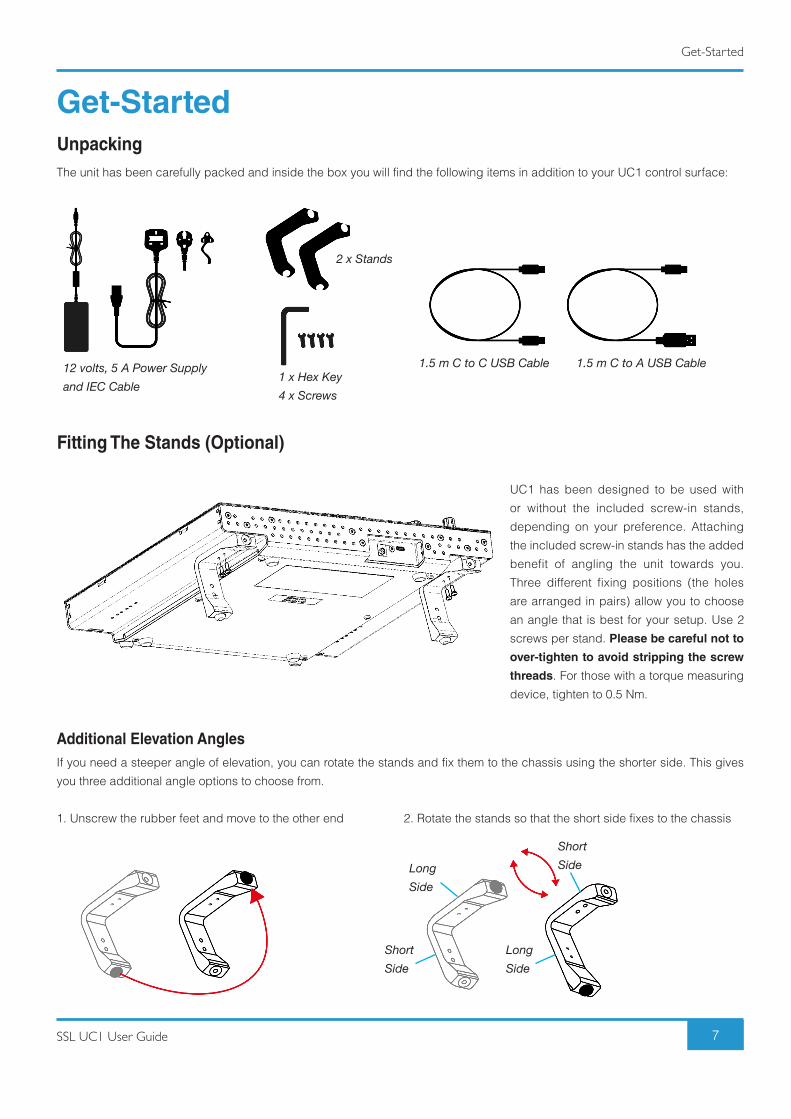
Get-StartedUnpackingThe unit has been carefully packed and inside the box you will find the following items in addition to your UC1 control surface:
Fitting The Stands (Optional)
UC1 has been designed to be used with
or without the included screw-in stands,
depending on your preference. Attaching
the included screw-in stands has the added
benefit of angling the unit towards you.
Three different fixing positions (the holes
are arranged in pairs) allow you to choose
an angle that is best for your setup. Use 2
screws per stand. Please be careful not to
over-tighten to avoid stripping the screw
threads. For those with a torque measuring
device, tighten to 0.5 Nm.
Additional Elevation AnglesIf you need a steeper angle of elevation, you can rotate the stands and fix them to the chassis using the shorter side. This gives
you three additional angle options to choose from.
1. Unscrew the rubber feet and move to the other end 2. Rotate the stands so that the short side fixes to the chassis
12 volts, 5 A Power Supply and IEC Cable
1.5 m C to C USB Cable 1.5 m C to A USB Cable
2 x Stands
ShortSide
LongSide
LongSide
ShortSide
1 x Hex Key4 x Screws
Get-Started
8 SSL UC1 User Guide
UC1 Physical Specification
Dimensions11.8 x 10.5 x 2.4 ” / 300 x 266 x 61 mm (Width x Depth X Height)
WeightUnboxed - 2.1 kg / 4.6 lbs
Boxed - 4.5 kg / 9.9 lbs
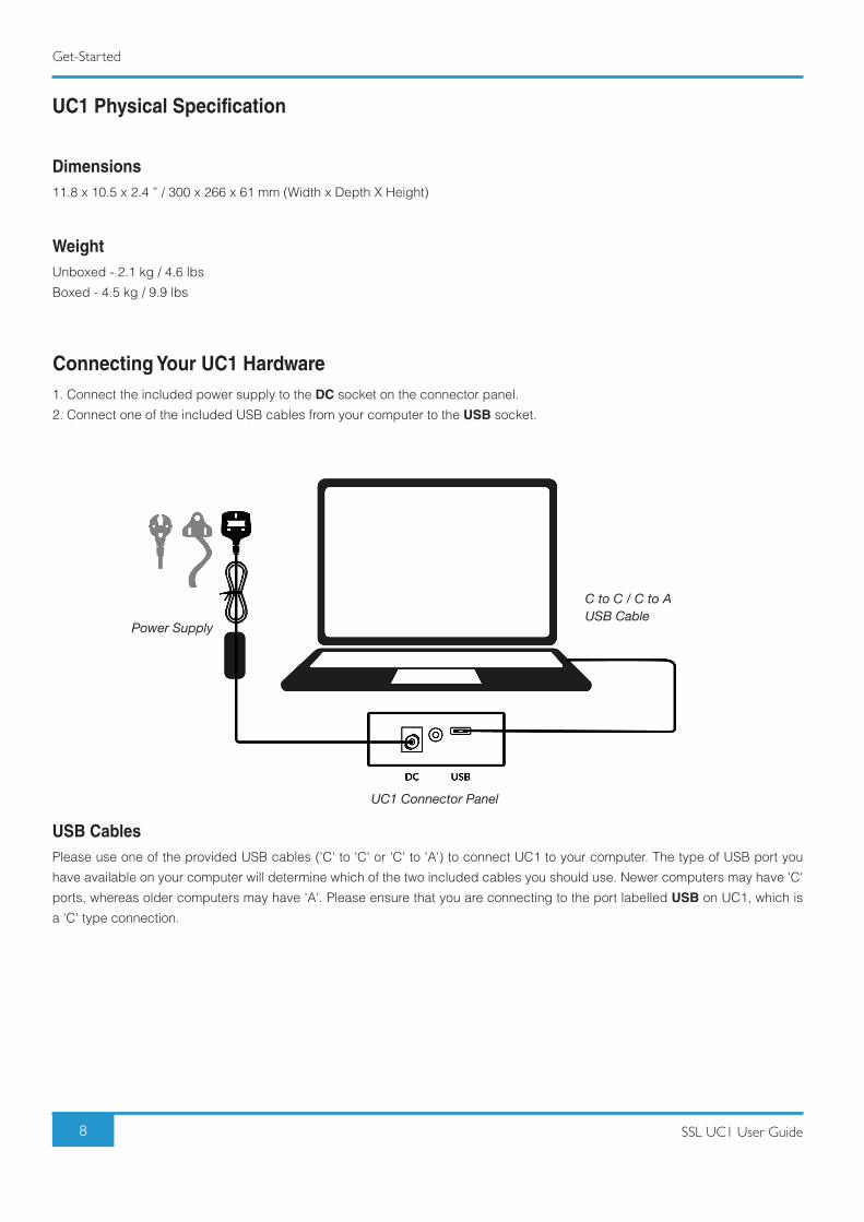
Connecting Your UC1 Hardware1. Connect the included power supply to the DC socket on the connector panel.
2. Connect one of the included USB cables from your computer to the USB socket.
USB CablesPlease use one of the provided USB cables ('C' to 'C' or 'C' to 'A') to connect UC1 to your computer. The type of USB port you
have available on your computer will determine which of the two included cables you should use. Newer computers may have 'C'
ports, whereas older computers may have 'A'. Please ensure that you are connecting to the port labelled USB on UC1, which is
a 'C' type connection.
C to C / C to AUSB Cable
Power Supply
UC1 Connector Panel
Get-Started
9SSL UC1 User Guide
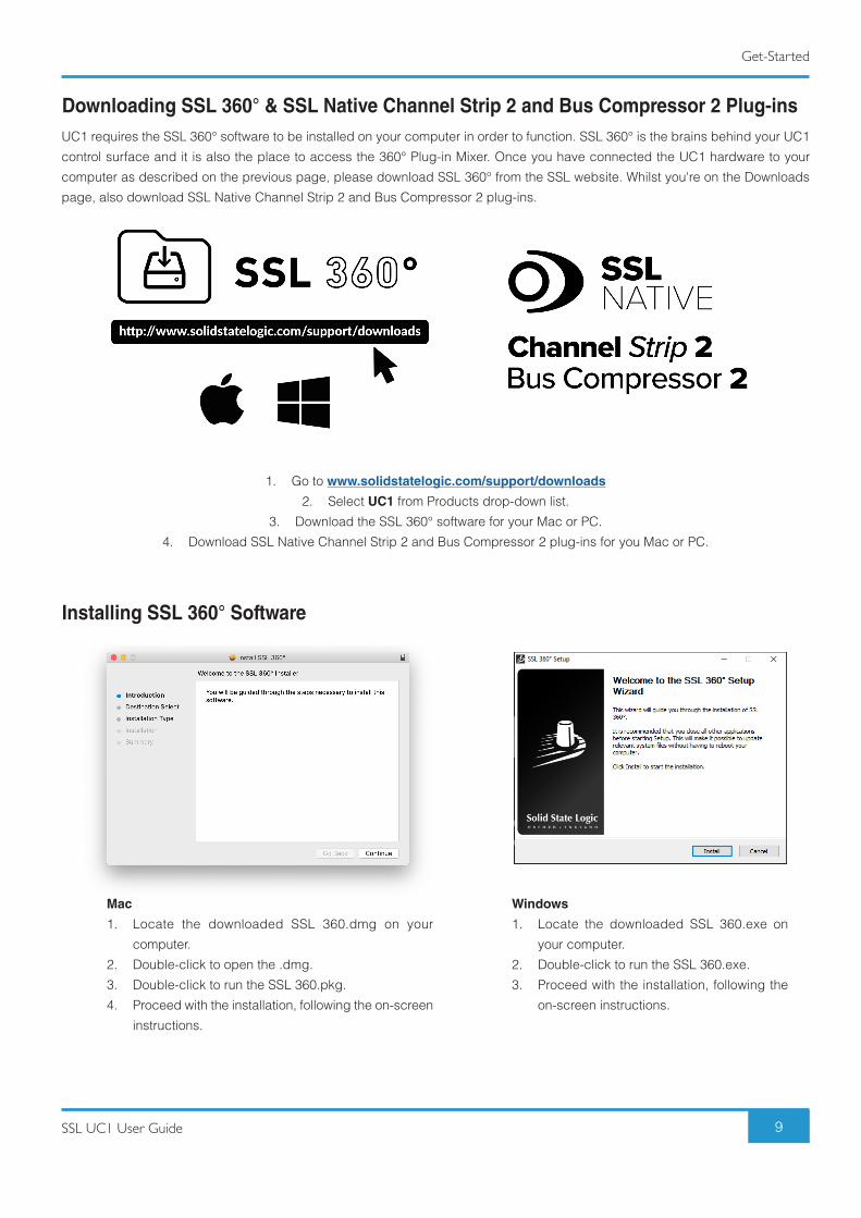
Downloading SSL 360° & SSL Native Channel Strip 2 and Bus Compressor 2 Plug-insUC1 requires the SSL 360° software to be installed on your computer in order to function. SSL 360° is the brains behind your UC1
control surface and it is also the place to access the 360° Plug-in Mixer. Once you have connected the UC1 hardware to your
computer as described on the previous page, please download SSL 360° from the SSL website. Whilst you're on the Downloads
page, also download SSL Native Channel Strip 2 and Bus Compressor 2 plug-ins.
1. Go to www.solidstatelogic.com/support/downloads
2. Select UC1 from Products drop-down list.
3. Download the SSL 360° software for your Mac or PC.
4. Download SSL Native Channel Strip 2 and Bus Compressor 2 plug-ins for you Mac or PC.
Installing SSL 360° Software
Mac
1. Locate the downloaded SSL 360.dmg on your
computer.
2. Double-click to open the .dmg.
3. Double-click to run the SSL 360.pkg.
4. Proceed with the installation, following the on-screen
instructions.
Windows
1. Locate the downloaded SSL 360.exe on
your computer.
2. Double-click to run the SSL 360.exe.
3. Proceed with the installation, following the
on-screen instructions.
Get-Started
10 SSL UC1 User Guide
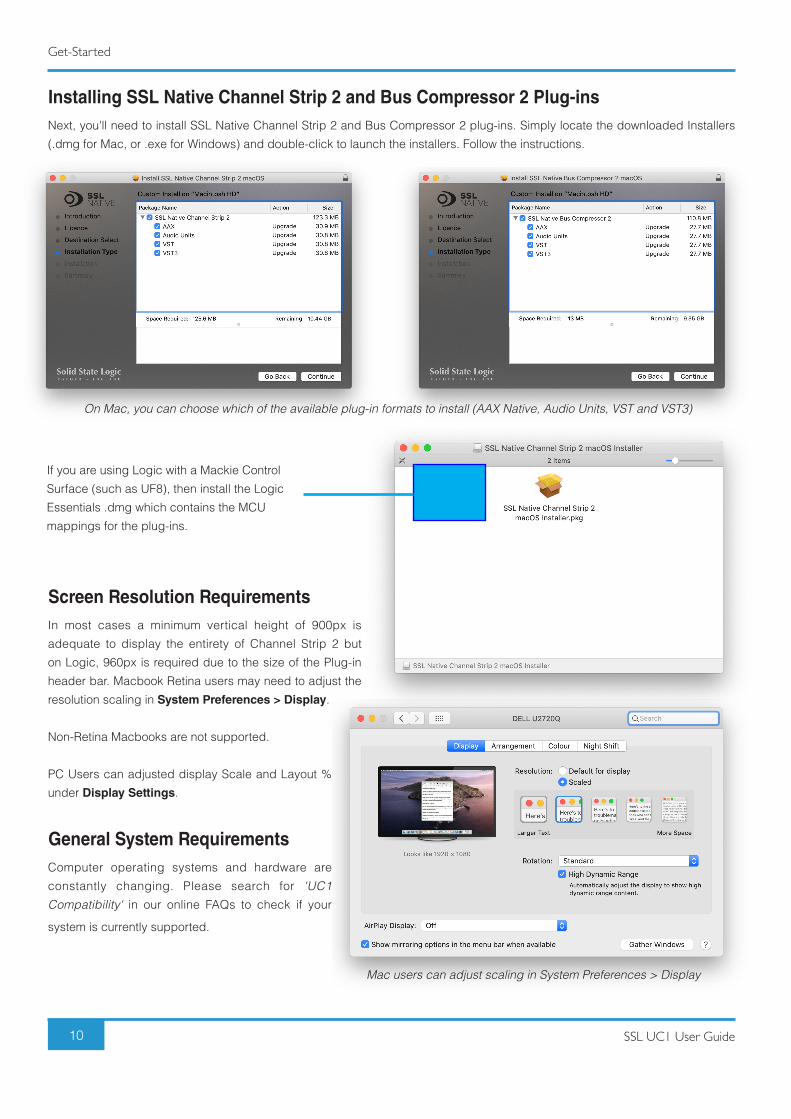
Installing SSL Native Channel Strip 2 and Bus Compressor 2 Plug-insNext, you'll need to install SSL Native Channel Strip 2 and Bus Compressor 2 plug-ins. Simply locate the downloaded Installers
(.dmg for Mac, or .exe for Windows) and double-click to launch the installers. Follow the instructions.
Screen Resolution RequirementsIn most cases a minimum vertical height of 900px is
adequate to display the entirety of Channel Strip 2 but
on Logic, 960px is required due to the size of the Plug-in
header bar. Macbook Retina users may need to adjust the
resolution scaling in System Preferences > Display.
Non-Retina Macbooks are not supported.
PC Users can adjusted display Scale and Layout %
under Display Settings.
General System RequirementsComputer operating systems and hardware are
constantly changing. Please search for 'UC1 Compatibility' in our online FAQs to check if your
system is currently supported.
If you are using Logic with a Mackie Control
Surface (such as UF8), then install the Logic
Essentials .dmg which contains the MCU
mappings for the plug-ins.
On Mac, you can choose which of the available plug-in formats to install (AAX Native, Audio Units, VST and VST3)
Mac users can adjust scaling in System Preferences > Display
Get-Started
11SSL UC1 User Guide
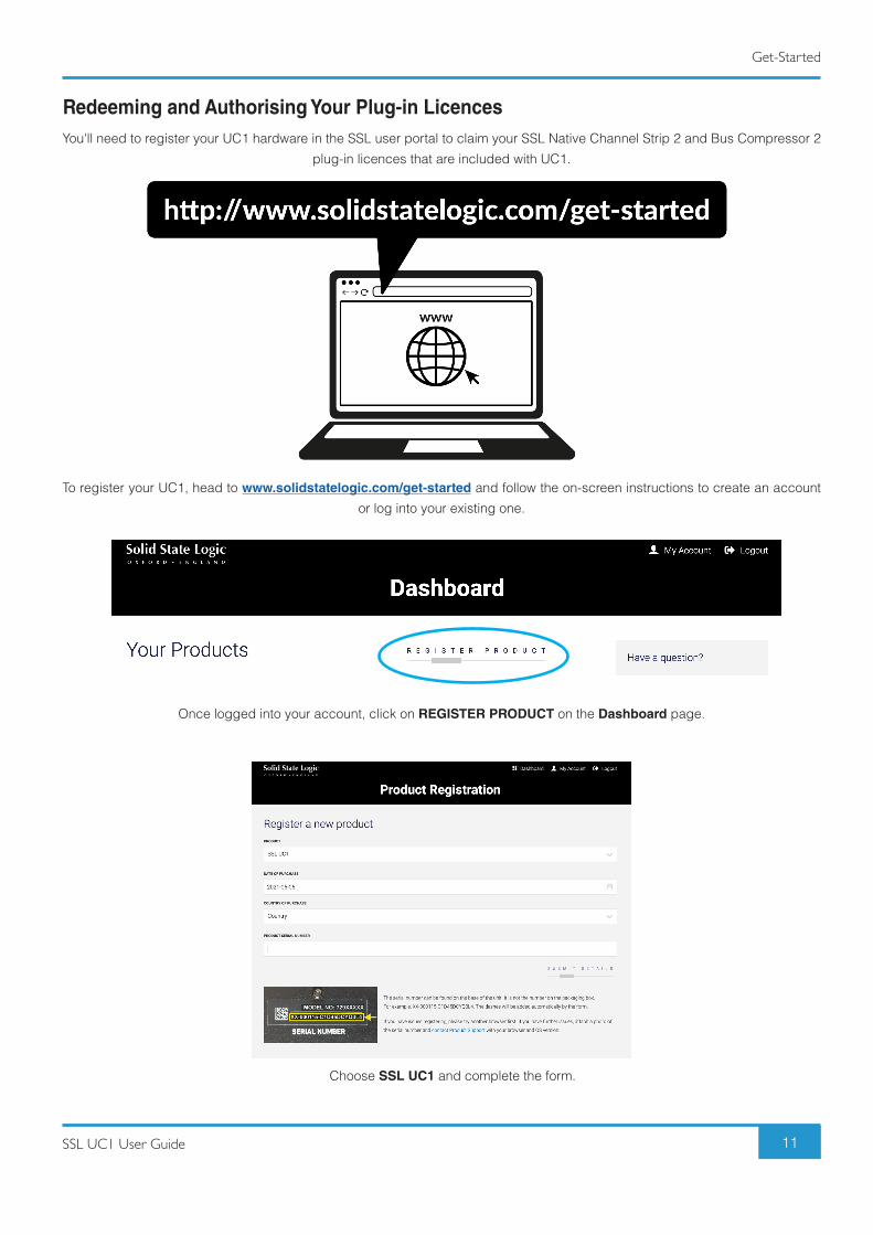
Choose SSL UC1 and complete the form.
Redeeming and Authorising Your Plug-in LicencesYou'll need to register your UC1 hardware in the SSL user portal to claim your SSL Native Channel Strip 2 and Bus Compressor 2
plug-in licences that are included with UC1.
To register your UC1, head to www.solidstatelogic.com/get-started and follow the on-screen instructions to create an account
or log into your existing one.
Once logged into your account, click on REGISTER PRODUCT on the Dashboard page.
Get-Started
12 SSL UC1 User Guide
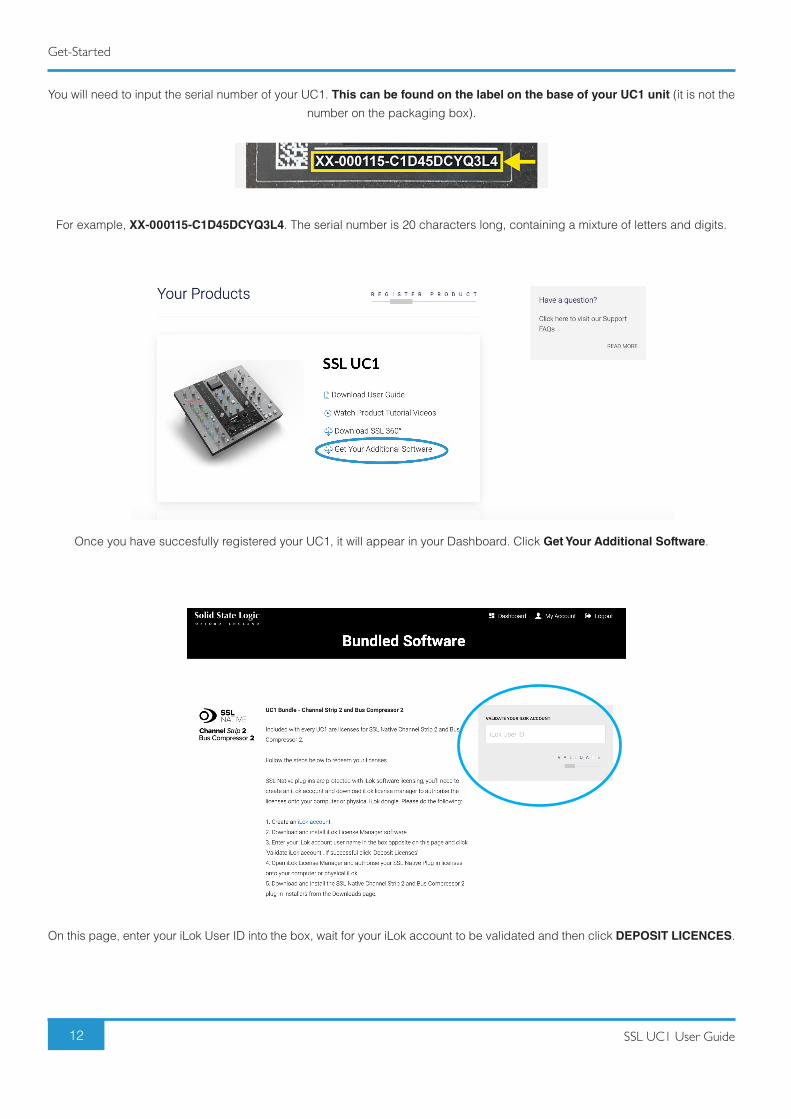
You will need to input the serial number of your UC1. This can be found on the label on the base of your UC1 unit (it is not the
number on the packaging box).
For example, XX-000115-C1D45DCYQ3L4. The serial number is 20 characters long, containing a mixture of letters and digits.
Once you have succesfully registered your UC1, it will appear in your Dashboard. Click Get Your Additional Software.
On this page, enter your iLok User ID into the box, wait for your iLok account to be validated and then click DEPOSIT LICENCES.
Get-Started
13SSL UC1 User Guide
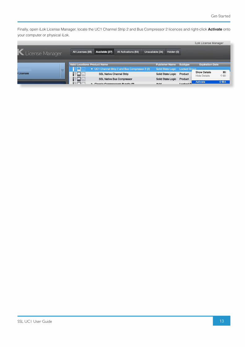
Finally, open iLok License Manager, locate the UC1 Channel Strip 2 and Bus Compressor 2 licences and right-click Activate onto
your computer or physical iLok.
Product Overview & Features
14 SSL UC1 User Guide
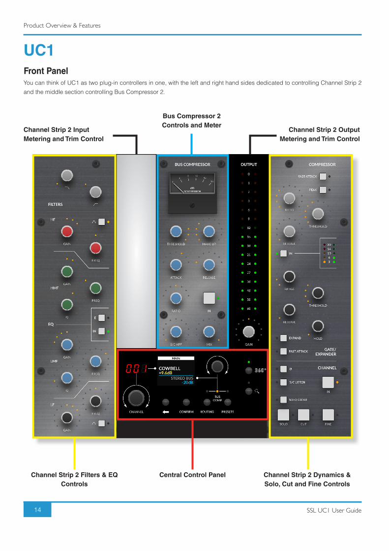
UC1Front PanelYou can think of UC1 as two plug-in controllers in one, with the left and right hand sides dedicated to controlling Channel Strip 2
and the middle section controlling Bus Compressor 2.
Channel Strip 2 Filters & EQ Controls
Central Control Panel
Bus Compressor 2Controls and Meter
Channel Strip 2 Input Metering and Trim Control
Channel Strip 2 Output Metering and Trim Control
Channel Strip 2 Dynamics & Solo, Cut and Fine Controls
Product Overview & Features
15SSL UC1 User Guide
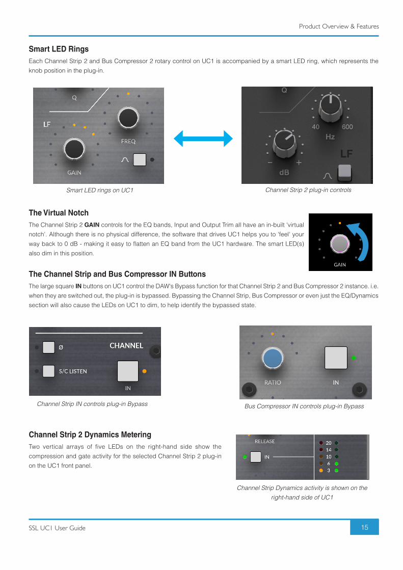
Smart LED RingsEach Channel Strip 2 and Bus Compressor 2 rotary control on UC1 is accompanied by a smart LED ring, which represents the
knob position in the plug-in.
The Virtual Notch The Channel Strip 2 GAIN controls for the EQ bands, Input and Output Trim all have an in-built 'virtual
notch'. Although there is no physical difference, the software that drives UC1 helps you to 'feel' your
way back to 0 dB - making it easy to flatten an EQ band from the UC1 hardware. The smart LED(s)
also dim in this position.
The Channel Strip and Bus Compressor IN ButtonsThe large square IN buttons on UC1 control the DAW's Bypass function for that Channel Strip 2 and Bus Compressor 2 instance. i.e.
when they are switched out, the plug-in is bypassed. Bypassing the Channel Strip, Bus Compressor or even just the EQ/Dynamics
section will also cause the LEDs on UC1 to dim, to help identify the bypassed state.
Channel Strip 2 Dynamics MeteringTwo vertical arrays of five LEDs on the right-hand side show the
compression and gate activity for the selected Channel Strip 2 plug-in
on the UC1 front panel.
Smart LED rings on UC1
Channel Strip IN controls plug-in Bypass Bus Compressor IN controls plug-in Bypass
Channel Strip Dynamics activity is shown on the right-hand side of UC1
Channel Strip 2 plug-in controls
Product Overview & Features
16 SSL UC1 User Guide
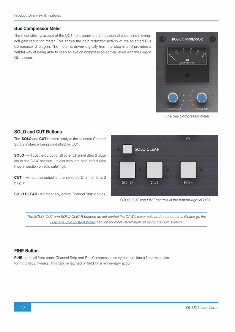
Bus Compressor MeterThe most striking aspect of the UC1 front panel is the inclusion of a genuine moving-
coil gain reduction meter. This shows the gain reduction activity of the selected Bus
Compressor 2 plug-in. The meter is driven digitally from the plug-in and provides a
helpful way of being able to keep an eye on compression activity, even with the Plug-in
GUI closed.
SOLO and CUT ButtonsThe SOLO and CUT buttons apply to the selected Channel
Strip 2 instance being controlled by UC1.
SOLO - will cut the output of all other Channel Strip 2 plug-
ins in the DAW session, unless they are solo safed (see
Plug-in section on solo safe'ing).
CUT - will cut the output of the selected Channel Strip 2
plug-in.
SOLO CLEAR - will clear any active Channel Strip 2 solos.
The SOLO, CUT and SOLO CLEAR buttons do not control the DAW's mixer solo and mute buttons. Please go the How The Solo System Works section for more information on using the Solo system.
FINE ButtonFINE - puts all front panel Channel Strip and Bus Compressor rotary controls into a finer resolution,
for mix critical tweaks. This can be latched or held for a momentary action.
The Bus Compressor meter
SOLO, CUT and FINE controls in the bottom-right of UC1
Product Overview & Features
17SSL UC1 User Guide
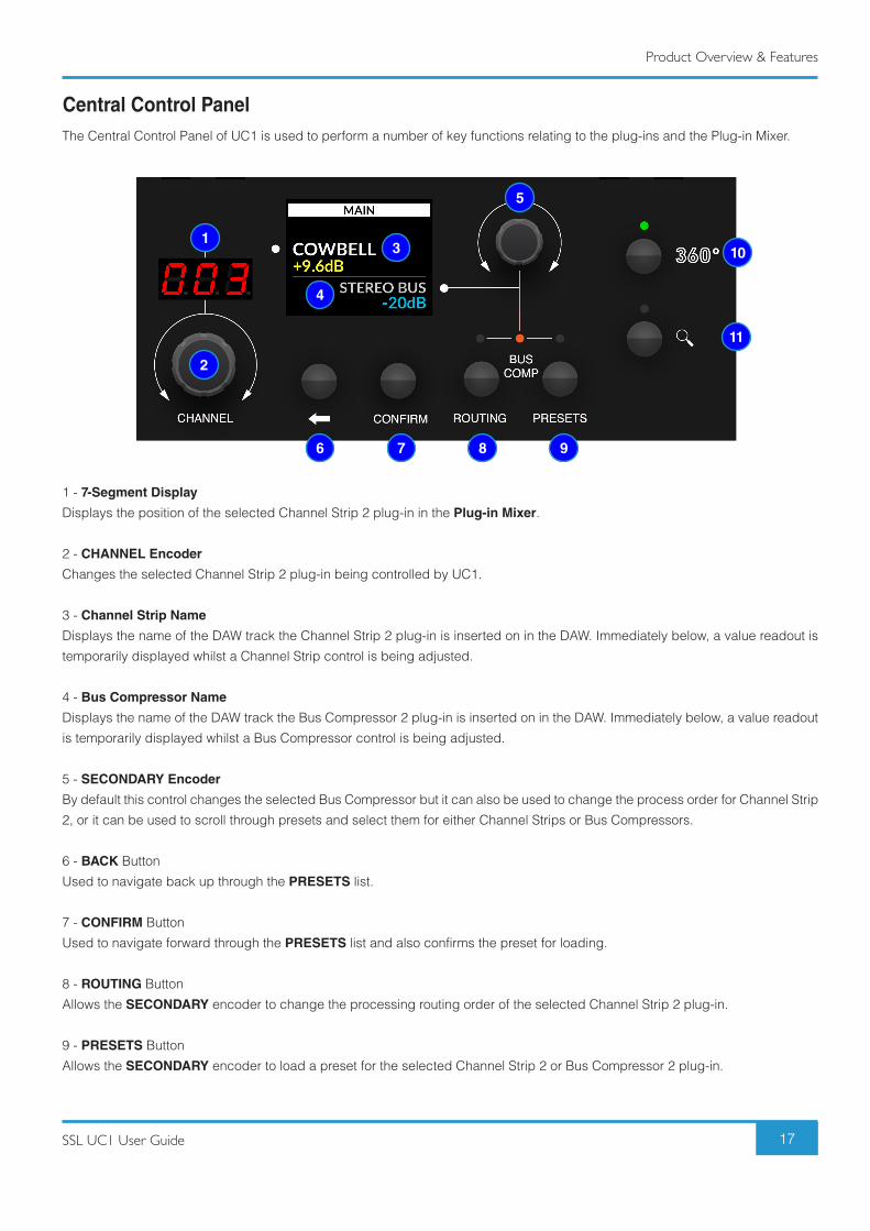
Central Control PanelThe Central Control Panel of UC1 is used to perform a number of key functions relating to the plug-ins and the Plug-in Mixer.
1 - 7-Segment Display
Displays the position of the selected Channel Strip 2 plug-in in the Plug-in Mixer.
2 - CHANNEL Encoder
Changes the selected Channel Strip 2 plug-in being controlled by UC1.
3 - Channel Strip Name
Displays the name of the DAW track the Channel Strip 2 plug-in is inserted on in the DAW. Immediately below, a value readout is
temporarily displayed whilst a Channel Strip control is being adjusted.
4 - Bus Compressor Name
Displays the name of the DAW track the Bus Compressor 2 plug-in is inserted on in the DAW. Immediately below, a value readout
is temporarily displayed whilst a Bus Compressor control is being adjusted.
5 - SECONDARY Encoder
By default this control changes the selected Bus Compressor but it can also be used to change the process order for Channel Strip
2, or it can be used to scroll through presets and select them for either Channel Strips or Bus Compressors.
6 - BACK Button
Used to navigate back up through the PRESETS list.
7 - CONFIRM Button
Used to navigate forward through the PRESETS list and also confirms the preset for loading.
8 - ROUTING Button
Allows the SECONDARY encoder to change the processing routing order of the selected Channel Strip 2 plug-in.
9 - PRESETS Button
Allows the SECONDARY encoder to load a preset for the selected Channel Strip 2 or Bus Compressor 2 plug-in.
3
5
4
6 7 8 9
10
11
1
2
Product Overview & Features
18 SSL UC1 User Guide
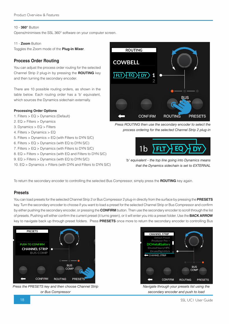
10 - 360° Button
Opens/minimises the SSL 360° software on your computer screen.
11 - Zoom Button
Toggles the Zoom mode of the Plug-in Mixer.
Process Order RoutingYou can adjust the process order routing for the selected
Channel Strip 2 plug-in by pressing the ROUTING key
and then turning the secondary encoder.
There are 10 possible routing orders, as shown in the
table below. Each routing order has a 'b' equivalent,
which sources the Dynamics sidechain externally.
Processing Order Options
1. Filters > EQ > Dynamics (Default)
2. EQ > Filters > Dynamics
3. Dynamics > EQ > Filters
4. Filters > Dynamics > EQ
5. Filters > Dynamics > EQ (with Filters to DYN S/C)
6. Filters > EQ > Dynamics (with EQ to DYN S/C)
7. Filters > EQ > Dynamics (with Filters to DYN S/C)
8. EQ > Filters > Dynamics (with EQ and Filters to DYN S/C)
9. EQ > Filters > Dynamics (with EQ to DYN S/C)
10. EQ > Dynamics > Filters (with DYN and Filters to DYN S/C)
To return the secondary encoder to controlling the selected Bus Compressor, simply press the ROUTING key again.
PresetsYou can load presets for the selected Channel Strip 2 or Bus Compressor 2 plug-in directly from the surface by pressing the PRESETS
key. Turn the secondary encoder to choose if you want to load a preset for the selected Channel Strip or Bus Compressor and confirm
by either pushing the secondary encoder, or pressing the CONFIRM button. Then use the secondary encoder to scroll through the list
of presets. Pushing will either confirm the current preset (it turns green), or it will enter you into a preset folder. Use the BACK ARROW
key to navigate back up through preset folders. Press PRESETS once more to return the secondary encoder to controlling Bus
'b' equivalent - the top line going into Dynamics means that the Dynamics sidechain is set to EXTERNAL
Press ROUTING then use the secondary encoder to select the process ordering for the selected Channel Strip 2 plug-in
Press the PRESETS key and then choose Channel Strip or Bus Compressor
Navigate through your presets list using the secondary encoder and push to load
Product Overview & Features
19SSL UC1 User Guide
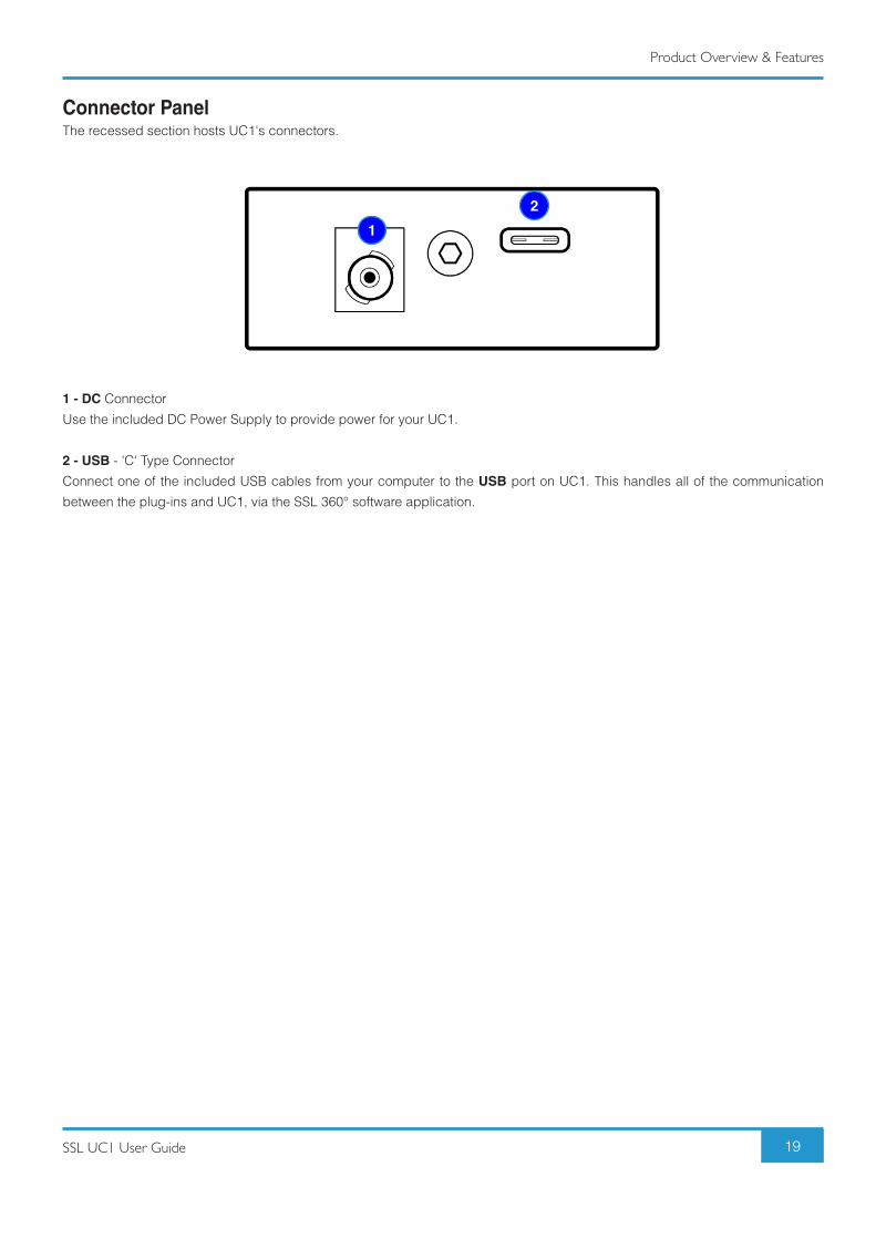
Connector PanelThe recessed section hosts UC1's connectors.
1 - DC Connector
Use the included DC Power Supply to provide power for your UC1.
2 - USB - 'C' Type Connector
Connect one of the included USB cables from your computer to the USB port on UC1. This handles all of the communication
between the plug-ins and UC1, via the SSL 360° software application.
1
2
Product Overview & Features
20 SSL UC1 User Guide
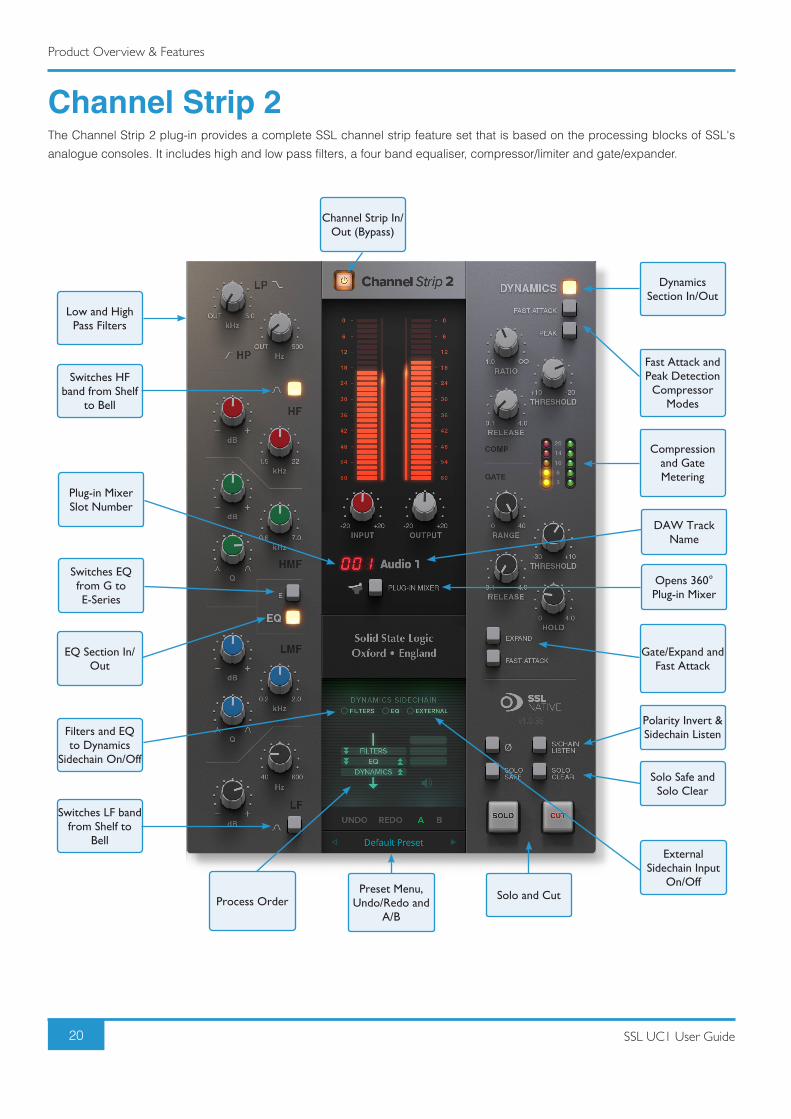
Channel Strip 2The Channel Strip 2 plug-in provides a complete SSL channel strip feature set that is based on the processing blocks of SSL's
analogue consoles. It includes high and low pass filters, a four band equaliser, compressor/limiter and gate/expander.
Low and High Pass Filters
Channel Strip In/Out (Bypass)
Dynamics Section In/Out
Fast Attack and Peak Detection
Compressor Modes
Compression and Gate Metering
DAW Track Name
Opens 360° Plug-in Mixer
Gate/Expand and Fast Attack
Polarity Invert & Sidechain Listen
Solo Safe and Solo Clear
Solo and CutPreset Menu, Undo/Redo and
A/BProcess Order
Switches HF band from Shelf
to Bell
Switches LF band from Shelf to
Bell
EQ Section In/Out
Filters and EQ to Dynamics
Sidechain On/Off
External Sidechain Input
On/Off
Switches EQ from G to E-Series
Plug-in Mixer Slot Number
Product Overview & Features
21SSL UC1 User Guide
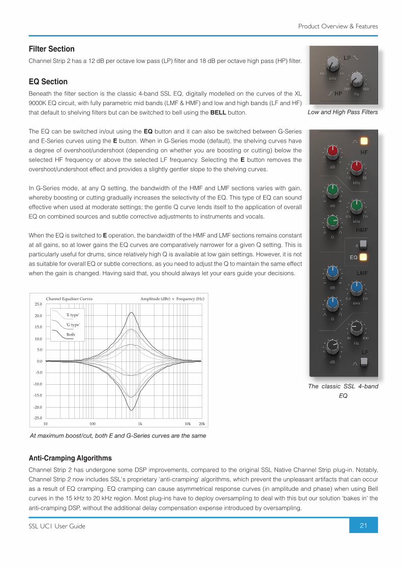
Filter SectionChannel Strip 2 has a 12 dB per octave low pass (LP) filter and 18 dB per octave high pass (HP) filter.
EQ SectionBeneath the filter section is the classic 4-band SSL EQ, digitally modelled on the curves of the XL
9000K EQ circuit, with fully parametric mid bands (LMF & HMF) and low and high bands (LF and HF)
that default to shelving filters but can be switched to bell using the BELL button.
The EQ can be switched in/out using the EQ button and it can also be switched between G-Series
and E-Series curves using the E button. When in G-Series mode (default), the shelving curves have
a degree of overshoot/undershoot (depending on whether you are boosting or cutting) below the
selected HF frequency or above the selected LF frequency. Selecting the E button removes the
overshoot/undershoot effect and provides a slightly gentler slope to the shelving curves.
In G-Series mode, at any Q setting, the bandwidth of the HMF and LMF sections varies with gain,
whereby boosting or cutting gradually increases the selectivity of the EQ. This type of EQ can sound
effective when used at moderate settings; the gentle Q curve lends itself to the application of overall
EQ on combined sources and subtle corrective adjustments to instruments and vocals.
When the EQ is switched to E operation, the bandwidth of the HMF and LMF sections remains constant
at all gains, so at lower gains the EQ curves are comparatively narrower for a given Q setting. This is
particularly useful for drums, since relatively high Q is available at low gain settings. However, it is not
as suitable for overall EQ or subtle corrections, as you need to adjust the Q to maintain the same effect
when the gain is changed. Having said that, you should always let your ears guide your decisions.
Anti-Cramping Algorithms
Channel Strip 2 has undergone some DSP improvements, compared to the original SSL Native Channel Strip plug-in. Notably,
Channel Strip 2 now includes SSL's proprietary 'anti-cramping' algorithms, which prevent the unpleasant artifacts that can occur
as a result of EQ cramping. EQ cramping can cause asymmetrical response curves (in amplitude and phase) when using Bell
curves in the 15 kHz to 20 kHz region. Most plug-ins have to deploy oversampling to deal with this but our solution 'bakes in' the
anti-cramping DSP, without the additional delay compensation expense introduced by oversampling.
10 100 1k 10k 20k-25.0
-20.0
-15.0
-10.0
-5.0
0.0
5.0
10.0
15.0
20.0
25.0Amplitude (dBr) v Frequency (Hz)Channel Equaliser Curves
'G type'
'E type'
Both
Low and High Pass Filters
The classic SSL 4-band EQ
At maximum boost/cut, both E and G-Series curves are the same
Product Overview & Features
22 SSL UC1 User Guide
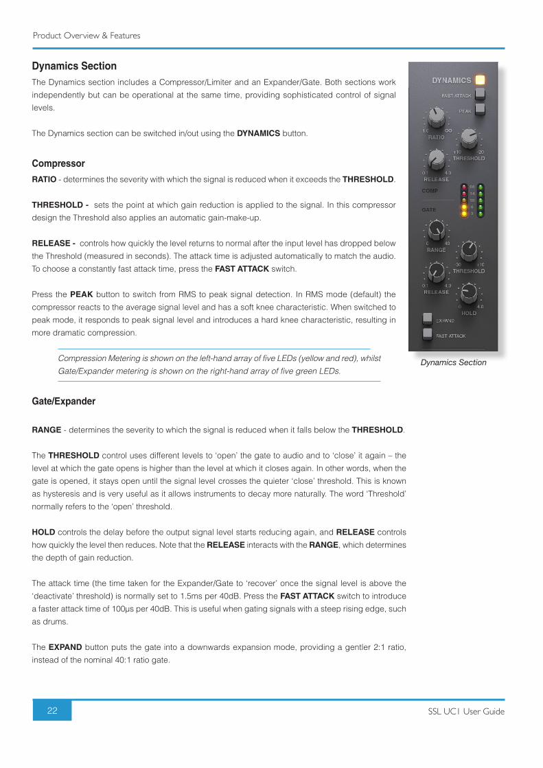
Dynamics SectionThe Dynamics section includes a Compressor/Limiter and an Expander/Gate. Both sections work
independently but can be operational at the same time, providing sophisticated control of signal
levels.
The Dynamics section can be switched in/out using the DYNAMICS button.
Compressor
RATIO - determines the severity with which the signal is reduced when it exceeds the THRESHOLD.
THRESHOLD - sets the point at which gain reduction is applied to the signal. In this compressor
design the Threshold also applies an automatic gain-make-up.
RELEASE - controls how quickly the level returns to normal after the input level has dropped below
the Threshold (measured in seconds). The attack time is adjusted automatically to match the audio.
To choose a constantly fast attack time, press the FAST ATTACK switch.
Press the PEAK button to switch from RMS to peak signal detection. In RMS mode (default) the
compressor reacts to the average signal level and has a soft knee characteristic. When switched to
peak mode, it responds to peak signal level and introduces a hard knee characteristic, resulting in
more dramatic compression.
Compression Metering is shown on the left-hand array of five LEDs (yellow and red), whilst Gate/Expander metering is shown on the right-hand array of five green LEDs.
Gate/Expander
RANGE - determines the severity to which the signal is reduced when it falls below the THRESHOLD.
The THRESHOLD control uses different levels to ‘open’ the gate to audio and to ‘close’ it again – the
level at which the gate opens is higher than the level at which it closes again. In other words, when the
gate is opened, it stays open until the signal level crosses the quieter ‘close’ threshold. This is known
as hysteresis and is very useful as it allows instruments to decay more naturally. The word ‘Threshold’
normally refers to the ‘open’ threshold.
HOLD controls the delay before the output signal level starts reducing again, and RELEASE controls
how quickly the level then reduces. Note that the RELEASE interacts with the RANGE, which determines
the depth of gain reduction.
The attack time (the time taken for the Expander/Gate to ‘recover’ once the signal level is above the
‘deactivate’ threshold) is normally set to 1.5ms per 40dB. Press the FAST ATTACK switch to introduce
a faster attack time of 100µs per 40dB. This is useful when gating signals with a steep rising edge, such
as drums.
The EXPAND button puts the gate into a downwards expansion mode, providing a gentler 2:1 ratio,
instead of the nominal 40:1 ratio gate.
Dynamics Section
Product Overview & Features
23SSL UC1 User Guide
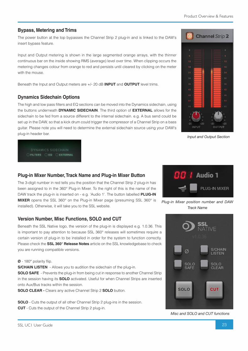
Bypass, Metering and TrimsThe power button at the top bypasses the Channel Strip 2 plug-in and is linked to the DAW's
insert bypass feature.
Input and Output metering is shown in the large segmented orange arrays, with the thinner
continuous bar on the inside showing RMS (average) level over time. When clipping occurs the
metering changes colour from orange to red and persists until cleared by clicking on the meter
with the mouse.
Beneath the Input and Output meters are +/- 20 dB INPUT and OUTPUT level trims.
Dynamics Sidechain OptionsThe high and low pass filters and EQ sections can be moved into the Dynamics sidechain, using
the buttons underneath DYNAMIC SIDECHAIN. The third option of EXTERNAL allows for the
sidechain to be fed from a source different to the internal sidechain. e.g. A bus send could be
set up in the DAW, so that a kick drum could trigger the compressor of a Channel Strip on a bass
guitar. Please note you will need to determine the external sidechain source using your DAW's
plug-in header bar.
Plug-in Mixer Number, Track Name and Plug-in Mixer ButtonThe 3-digit number in red tells you the position that the Channel Strip 2 plug-in has
been assigned to in the 360° Plug-in Mixer. To the right of this is the name of the
DAW track the plug-in is inserted on - e.g. 'Audio 1'. The button labelled PLUG-IN
MIXER opens the SSL 360° on the Plug-in Mixer page (presuming SSL 360° is
installed). Otherwise, it will take you to the SSL website.
Version Number, Misc Functions, SOLO and CUTBeneath the SSL Native logo, the version of the plug-in is displayed e.g. 1.0.36. This
is important to pay attention to because SSL 360° releases will sometimes require a
certain version of plug-in to be installed in order for the system to function correctly.
Please check the SSL 360° Release Notes article on the SSL knowledgebase to check
you are running compatible versions.
Ø - 180° polarity flip.
S/CHAIN LISTEN - Allows you to audition the sidechain of the plug-in.
SOLO SAFE - Prevents the plug-in from being cut in response to another Channel Strip
in the session having its SOLO activated. Useful for when Channel Strips are inserted
onto Aux/Bus tracks within the session.
SOLO CLEAR - Clears any active Channel Strip 2 SOLO button.
SOLO - Cuts the output of all other Channel Strip 2 plug-ins in the session.
CUT - Cuts the output of the Channel Strip 2 plug-in.
Input and Output Section
Misc and SOLO and CUT functions
Plug-in Mixer position number and DAW Track Name
Product Overview & Features
24 SSL UC1 User Guide
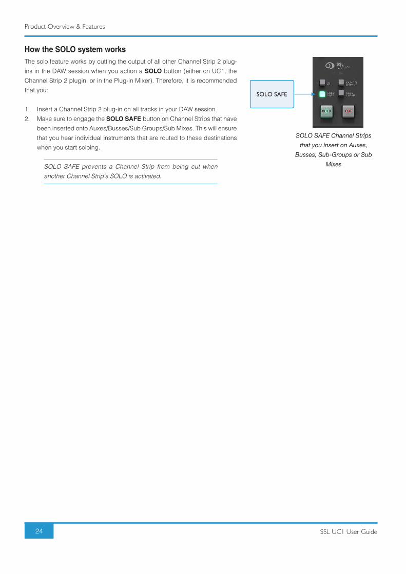
How the SOLO system worksThe solo feature works by cutting the output of all other Channel Strip 2 plug-
ins in the DAW session when you action a SOLO button (either on UC1, the
Channel Strip 2 plugin, or in the Plug-in Mixer). Therefore, it is recommended
that you:
1. Insert a Channel Strip 2 plug-in on all tracks in your DAW session.
2. Make sure to engage the SOLO SAFE button on Channel Strips that have
been inserted onto Auxes/Busses/Sub Groups/Sub Mixes. This will ensure
that you hear individual instruments that are routed to these destinations
when you start soloing.
SOLO SAFE prevents a Channel Strip from being cut when another Channel Strip's SOLO is activated.
SOLO SAFE Channel Strips that you insert on Auxes,
Busses, Sub-Groups or Sub Mixes
SOLO SAFE
Product Overview & Features
25SSL UC1 User Guide
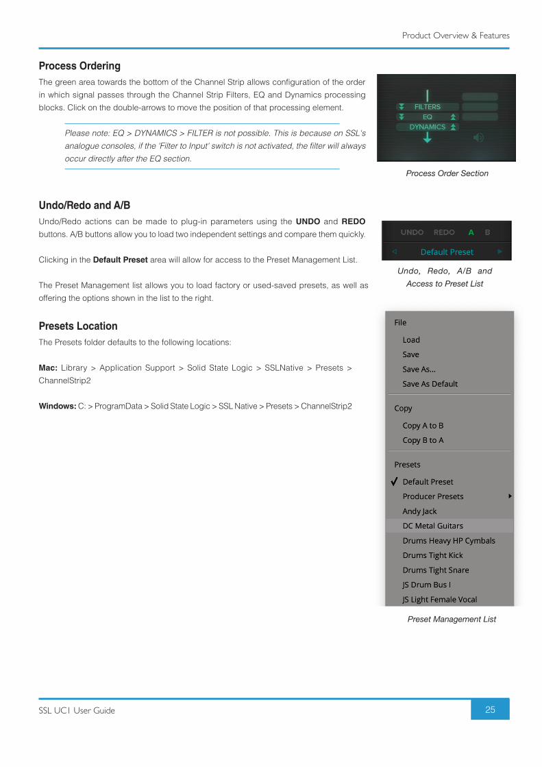
Process OrderingThe green area towards the bottom of the Channel Strip allows configuration of the order
in which signal passes through the Channel Strip Filters, EQ and Dynamics processing
blocks. Click on the double-arrows to move the position of that processing element.
Please note: EQ > DYNAMICS > FILTER is not possible. This is because on SSL's analogue consoles, if the 'Filter to Input' switch is not activated, the filter will always occur directly after the EQ section.
Undo/Redo and A/BUndo/Redo actions can be made to plug-in parameters using the UNDO and REDO
buttons. A/B buttons allow you to load two independent settings and compare them quickly.
Clicking in the Default Preset area will allow for access to the Preset Management List.
The Preset Management list allows you to load factory or used-saved presets, as well as
offering the options shown in the list to the right.
Presets LocationThe Presets folder defaults to the following locations:
Mac: Library > Application Support > Solid State Logic > SSLNative > Presets >
ChannelStrip2
Windows: C: > ProgramData > Solid State Logic > SSL Native > Presets > ChannelStrip2
Process Order Section
Preset Management List
Undo, Redo, A/B and Access to Preset List
Product Overview & Features
26 SSL UC1 User Guide
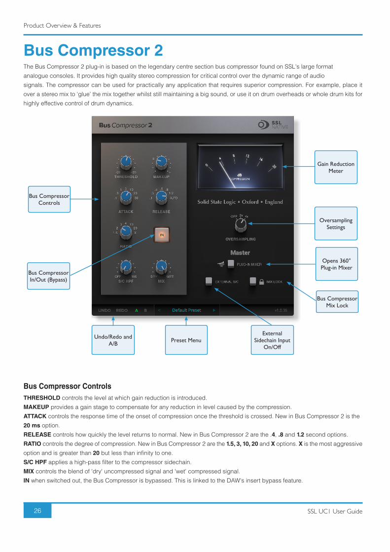
Bus Compressor 2The Bus Compressor 2 plug-in is based on the legendary centre section bus compressor found on SSL's large format
analogue consoles. It provides high quality stereo compression for critical control over the dynamic range of audio
signals. The compressor can be used for practically any application that requires superior compression. For example, place it
over a stereo mix to ‘glue’ the mix together whilst still maintaining a big sound, or use it on drum overheads or whole drum kits for
highly effective control of drum dynamics.
Bus Compressor ControlsTHRESHOLD controls the level at which gain reduction is introduced.
MAKEUP provides a gain stage to compensate for any reduction in level caused by the compression.
ATTACK controls the response time of the onset of compression once the threshold is crossed. New in Bus Compressor 2 is the
20 ms option.
RELEASE controls how quickly the level returns to normal. New in Bus Compressor 2 are the .4, .8 and 1.2 second options.
RATIO controls the degree of compression. New in Bus Compressor 2 are the 1.5, 3, 10, 20 and X options. X is the most aggressive
option and is greater than 20 but less than infinity to one.
S/C HPF applies a high-pass filter to the compressor sidechain.
MIX controls the blend of 'dry' uncompressed signal and 'wet' compressed signal.
IN when switched out, the Bus Compressor is bypassed. This is linked to the DAW's insert bypass feature.
Gain Reduction Meter
Oversampling Settings
Opens 360° Plug-in Mixer
Bus Compressor Mix Lock
Preset MenuExternal
Sidechain Input On/Off
Undo/Redo and A/B
Bus Compressor Controls
Bus Compressor In/Out (Bypass)
Product Overview & Features
27SSL UC1 User Guide
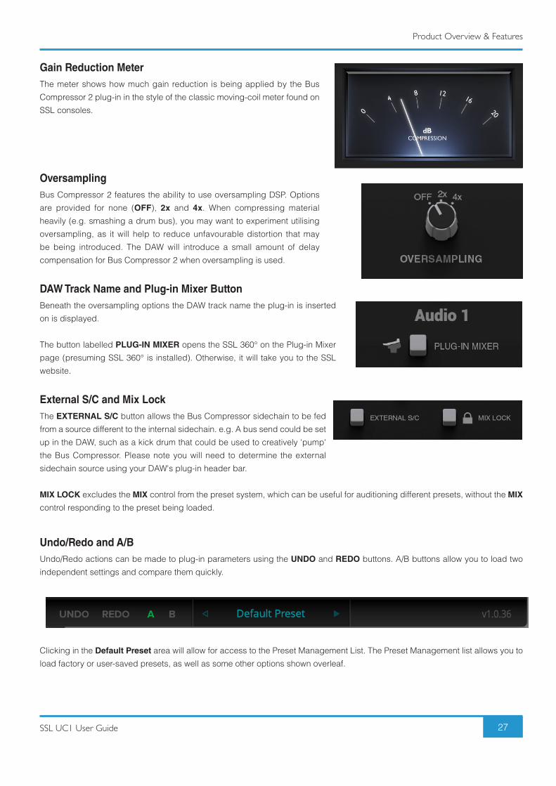
Gain Reduction MeterThe meter shows how much gain reduction is being applied by the Bus
Compressor 2 plug-in in the style of the classic moving-coil meter found on
SSL consoles.
OversamplingBus Compressor 2 features the ability to use oversampling DSP. Options
are provided for none (OFF), 2x and 4x. When compressing material
heavily (e.g. smashing a drum bus), you may want to experiment utilising
oversampling, as it will help to reduce unfavourable distortion that may
be being introduced. The DAW will introduce a small amount of delay
compensation for Bus Compressor 2 when oversampling is used.
DAW Track Name and Plug-in Mixer ButtonBeneath the oversampling options the DAW track name the plug-in is inserted
on is displayed.
The button labelled PLUG-IN MIXER opens the SSL 360° on the Plug-in Mixer
page (presuming SSL 360° is installed). Otherwise, it will take you to the SSL
website.
External S/C and Mix LockThe EXTERNAL S/C button allows the Bus Compressor sidechain to be fed
from a source different to the internal sidechain. e.g. A bus send could be set
up in the DAW, such as a kick drum that could be used to creatively 'pump'
the Bus Compressor. Please note you will need to determine the external
sidechain source using your DAW's plug-in header bar.
MIX LOCK excludes the MIX control from the preset system, which can be useful for auditioning different presets, without the MIX
control responding to the preset being loaded.
Undo/Redo and A/BUndo/Redo actions can be made to plug-in parameters using the UNDO and REDO buttons. A/B buttons allow you to load two
independent settings and compare them quickly.
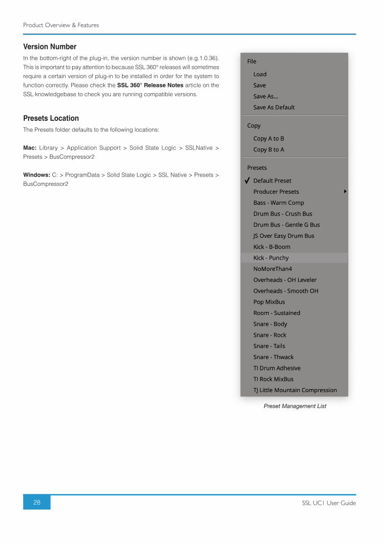
Clicking in the Default Preset area will allow for access to the Preset Management List. The Preset Management list allows you to
load factory or user-saved presets, as well as some other options shown overleaf.
Product Overview & Features
28 SSL UC1 User Guide
Version NumberIn the bottom-right of the plug-in, the version number is shown (e.g.1.0.36).
This is important to pay attention to because SSL 360° releases will sometimes
require a certain version of plug-in to be installed in order for the system to
function correctly. Please check the SSL 360° Release Notes article on the
SSL knowledgebase to check you are running compatible versions.
Presets LocationThe Presets folder defaults to the following locations:
Mac: Library > Application Support > Solid State Logic > SSLNative >
Presets > BusCompressor2
Windows: C: > ProgramData > Solid State Logic > SSL Native > Presets >
BusCompressor2
Preset Management List
Product Overview & Features
29SSL UC1 User Guide
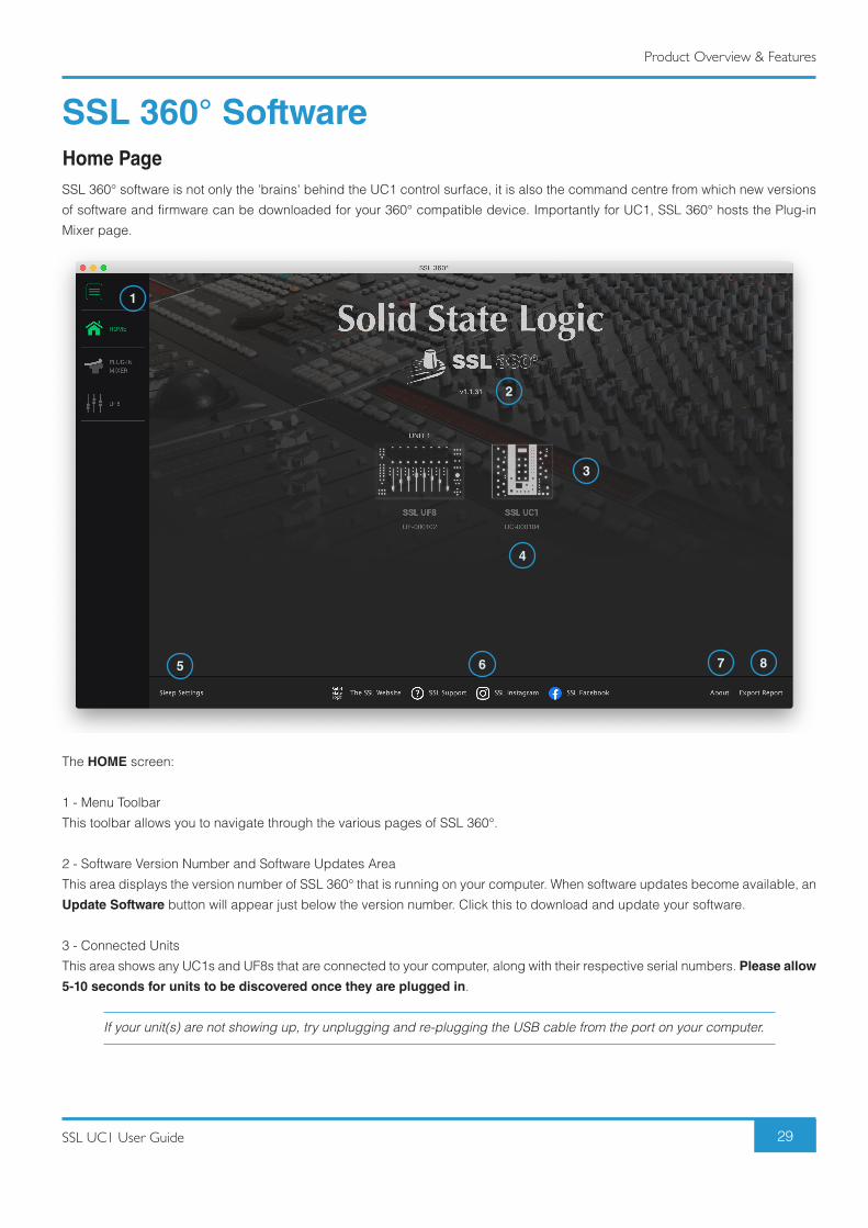
SSL 360° SoftwareHome PageSSL 360° software is not only the 'brains' behind the UC1 control surface, it is also the command centre from which new versions
of software and firmware can be downloaded for your 360° compatible device. Importantly for UC1, SSL 360° hosts the Plug-in
Mixer page.
The HOME screen:
1 - Menu Toolbar
This toolbar allows you to navigate through the various pages of SSL 360°.
2 - Software Version Number and Software Updates Area
This area displays the version number of SSL 360° that is running on your computer. When software updates become available, an
Update Software button will appear just below the version number. Click this to download and update your software.
3 - Connected Units
This area shows any UC1s and UF8s that are connected to your computer, along with their respective serial numbers. Please allow
5-10 seconds for units to be discovered once they are plugged in.
If your unit(s) are not showing up, try unplugging and re-plugging the USB cable from the port on your computer.
1
2
3
4
5 6 7 8
Product Overview & Features
30 SSL UC1 User Guide
4 - Firmware Updates Area
If a firmware update becomes available for your UC1 unit, then an Update Firmware button will appear below the unit. Click on
the button to start the firmware update process, being sure to not disconnect the power or USB cable(s) whilst it is in progress.
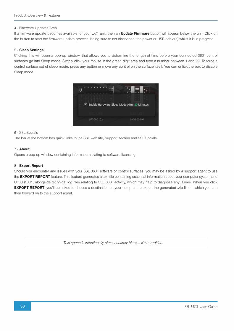
5 - Sleep Settings
Clicking this will open a pop-up window, that allows you to determine the length of time before your connected 360° control
surfaces go into Sleep mode. Simply click your mouse in the green digit area and type a number between 1 and 99. To force a
control surface out of sleep mode, press any button or move any control on the surface itself. You can untick the box to disable
Sleep mode.
6 - SSL Socials
The bar at the bottom has quick links to the SSL website, Support section and SSL Socials.
7 - About
Opens a pop-up window containing information relating to software licensing.
8 - Export Report
Should you encounter any issues with your SSL 360° software or control surfaces, you may be asked by a support agent to use
the EXPORT REPORT feature. This feature generates a text file containing essential information about your computer system and
UF8(s)/UC1, alongside technical log files relating to SSL 360° activity, which may help to diagnose any issues. When you click
EXPORT REPORT, you'll be asked to choose a destination on your computer to export the generated .zip file to, which you can
then forward on to the support agent.
This space is intentionally almost entirely blank... it's a tradition.
Product Overview & Features
31SSL UC1 User Guide
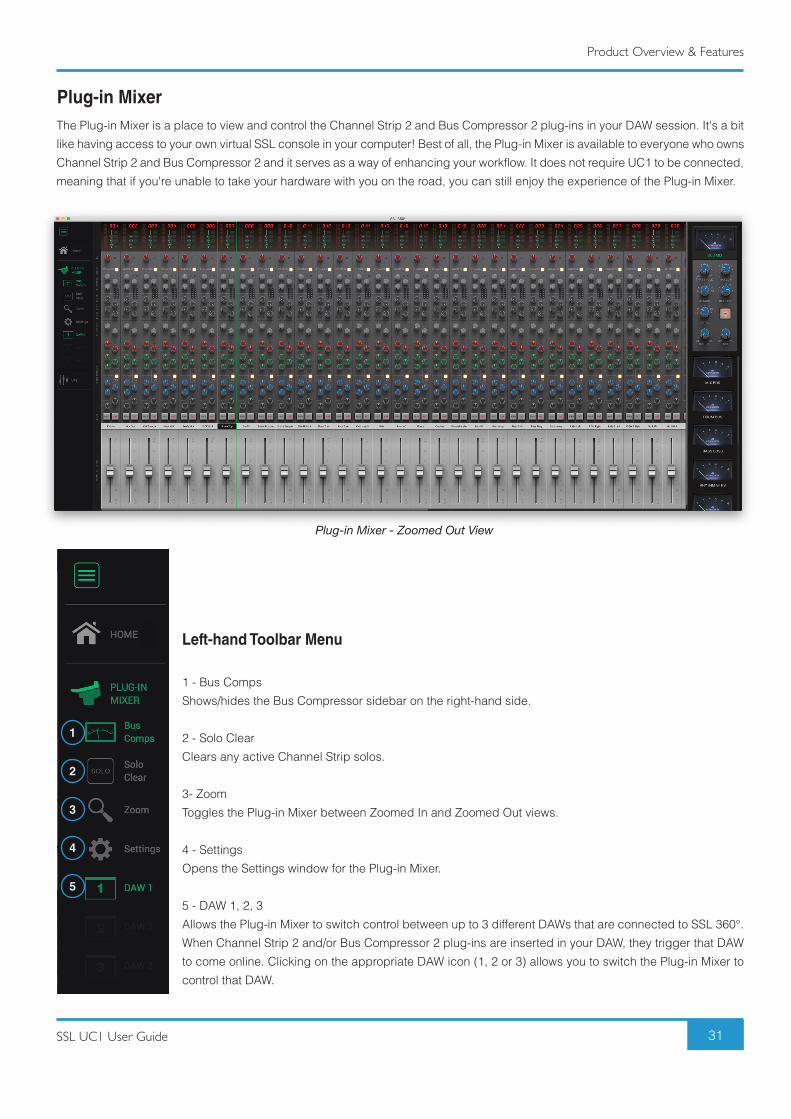
Plug-in MixerThe Plug-in Mixer is a place to view and control the Channel Strip 2 and Bus Compressor 2 plug-ins in your DAW session. It's a bit
like having access to your own virtual SSL console in your computer! Best of all, the Plug-in Mixer is available to everyone who owns
Channel Strip 2 and Bus Compressor 2 and it serves as a way of enhancing your workflow. It does not require UC1 to be connected,
meaning that if you're unable to take your hardware with you on the road, you can still enjoy the experience of the Plug-in Mixer.
Left-hand Toolbar Menu
1 - Bus Comps
Shows/hides the Bus Compressor sidebar on the right-hand side.
2 - Solo Clear
Clears any active Channel Strip solos.
3- Zoom
Toggles the Plug-in Mixer between Zoomed In and Zoomed Out views.
4 - Settings
Opens the Settings window for the Plug-in Mixer.
5 - DAW 1, 2, 3
Allows the Plug-in Mixer to switch control between up to 3 different DAWs that are connected to SSL 360°.
When Channel Strip 2 and/or Bus Compressor 2 plug-ins are inserted in your DAW, they trigger that DAW
to come online. Clicking on the appropriate DAW icon (1, 2 or 3) allows you to switch the Plug-in Mixer to
control that DAW.
Plug-in Mixer - Zoomed Out View
1
2
3
4
5
Product Overview & Features
32 SSL UC1 User Guide
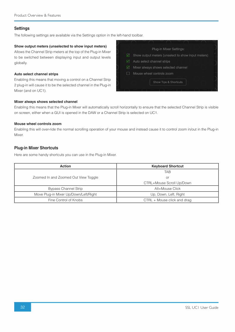
Settings
The following settings are available via the Settings option in the left-hand toolbar.
Show output meters (unselected to show input meters)
Allows the Channel Strip meters at the top of the Plug-in Mixer
to be switched between displaying input and output levels
globally.
Auto select channel strips
Enabling this means that moving a control on a Channel Strip
2 plug-in will cause it to be the selected channel in the Plug-in
Mixer (and on UC1).
Mixer always shows selected channel
Enabling this means that the Plug-in Mixer will automatically scroll horizontally to ensure that the selected Channel Strip is visible
on screen, either when a GUI is opened in the DAW or a Channel Strip is selected on UC1.
Mouse wheel controls zoom
Enabling this will over-ride the normal scrolling operation of your mouse and instead cause it to control zoom in/out in the Plug-in
Mixer.
Plug-in Mixer Shortcuts
Here are some handy shortcuts you can use in the Plug-in Mixer.
Action Keyboard Shortcut
Zoomed In and Zoomed Out View Toggle
TAB
or
CTRL+Mouse Scroll Up/Down
Bypass Channel Strip Alt+Mouse Click
Move Plug-in Mixer Up/Down/Left/Right Up, Down, Left, Right
Fine Control of Knobs CTRL + Mouse click and drag
Product Overview & Features
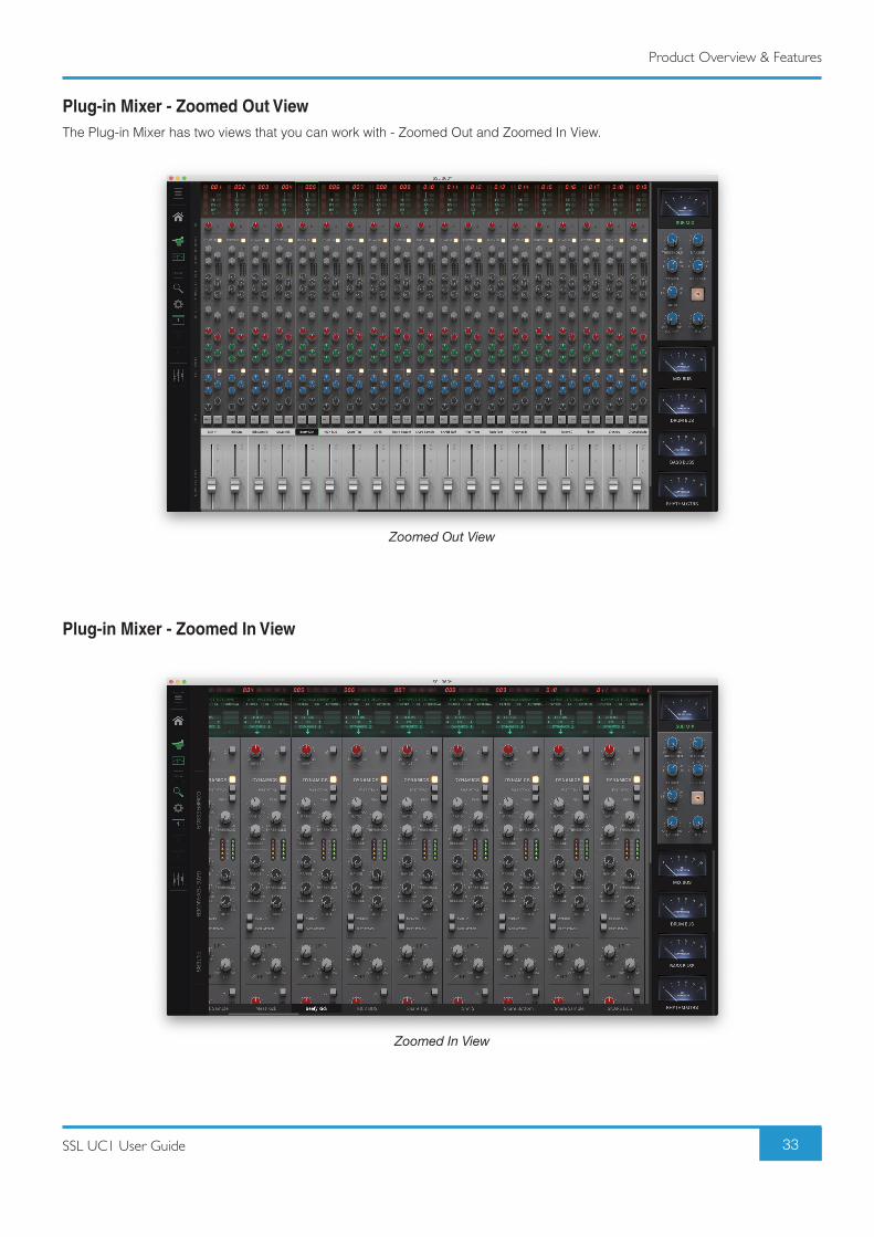
33SSL UC1 User Guide
Plug-in Mixer - Zoomed Out ViewThe Plug-in Mixer has two views that you can work with - Zoomed Out and Zoomed In View.
Plug-in Mixer - Zoomed In View
Zoomed Out View
Zoomed In View
Product Overview & Features
34 SSL UC1 User Guide
Zoomed Out View
• Easy to navigate from one end of the Plug-in Mixer to the other.
• Gives you a 'bird's eye' view of the mix.
• In DAWs that allow manual re-ordering, it allows you to re-arrange your Channel Strips by clicking and dragging in the track
name area.
• The +/- 20 dB Output Trim parameter is placed onto a fader.
You cannot change the Channel Strip processing order from Zoomed Out View
Zoomed In View
• Allows you to get into the detail of tweaking settings with precision.
• Allows access to alter Channel Strip Routing at the top.
• Allows access to SOLO SAFE and Sidechain Listen at the bottom.
You cannot re-order tracks (if DAW allows manual re-ordering) from Zoomed In View
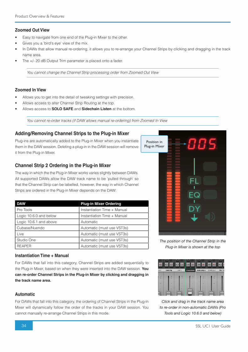
Adding/Removing Channel Strips to the Plug-in MixerPlug-ins are automatically added to the Plug-in Mixer when you instantiate
them in the DAW session. Deleting a plug-in in the DAW session will remove
it from the Plug-in Mixer.
Channel Strip 2 Ordering in the Plug-in MixerThe way in which the the Plug-in Mixer works varies slightly between DAWs.
All supported DAWs allow the DAW track name to be 'pulled through' so
that the Channel Strip can be labelled, however, the way in which Channel
Strips are ordered in the Plug-in Mixer depends on the DAW:
DAW Plug-in Mixer Ordering
Pro Tools Instantiation Time + Manual
Logic 10.6.0 and below Instantiation Time + Manual
Logic 10.6.1 and above Automatic
Cubase/Nuendo Automatic (must use VST3s)
Live Automatic (must use VST3s)
Studio One Automatic (must use VST3s)
REAPER Automatic (must use VST3s)
Position in Plug-in Mixer
The position of the Channel Strip in the Plug-in Mixer is shown at the top
Click and drag in the track name areato re-order in non-automatic DAWs (Pro
Tools and Logic 10.6.0 and below)
Instantiation Time + Manual
For DAWs that fall into this category, Channel Strips are added sequentially to
the Plug-in Mixer, based on when they were inserted into the DAW session. You
can re-order Channel Strips in the Plug-in Mixer by clicking and dragging in
the track name area.
Automatic
For DAWs that fall into this category, the ordering of Channel Strips in the Plug-in
Mixer will dynamically follow the order of the tracks in your DAW session. You
cannot manually re-arrange Channel Strips in this mode.
Product Overview & Features
35SSL UC1 User Guide
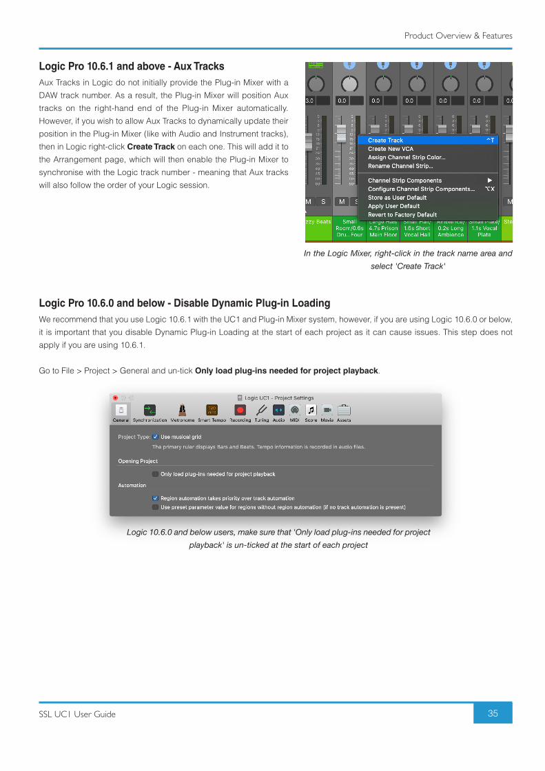
Logic Pro 10.6.1 and above - Aux TracksAux Tracks in Logic do not initially provide the Plug-in Mixer with a
DAW track number. As a result, the Plug-in Mixer will position Aux
tracks on the right-hand end of the Plug-in Mixer automatically.
However, if you wish to allow Aux Tracks to dynamically update their
position in the Plug-in Mixer (like with Audio and Instrument tracks),
then in Logic right-click Create Track on each one. This will add it to
the Arrangement page, which will then enable the Plug-in Mixer to
synchronise with the Logic track number - meaning that Aux tracks
will also follow the order of your Logic session.
Logic Pro 10.6.0 and below - Disable Dynamic Plug-in LoadingWe recommend that you use Logic 10.6.1 with the UC1 and Plug-in Mixer system, however, if you are using Logic 10.6.0 or below,
it is important that you disable Dynamic Plug-in Loading at the start of each project as it can cause issues. This step does not
apply if you are using 10.6.1.
Go to File > Project > General and un-tick Only load plug-ins needed for project playback.
In the Logic Mixer, right-click in the track name area and select 'Create Track'
Logic 10.6.0 and below users, make sure that 'Only load plug-ins needed for project playback' is un-ticked at the start of each project
Product Overview & Features
36 SSL UC1 User Guide
Adding/Removing Bus Compressors to the Plug-in MixerPlug-ins are automatically added to the Plug-in Mixer when you instantiate them in the DAW session. Deleting a plug-in in the DAW
session will remove it from the Plug-in Mixer.
Bus Compressor 2 Ordering in the Plug-in Mixer
Bus Compressor plug-ins appear on the right-hand side of the Plug-in Mixer, as they are added to the DAW session. Up to 8 Bus
Compressors can appear in the list and therefore 8 can be switched between on UC1. The DAW session itself can have as many
Bus Compressor 2 plug-ins as you like but if you've reached 8 in the Plug-in Mixer, you'll need to delete some to get access to
them again on UC1. It is not possible to re-order Bus Compressors in the sidebar.
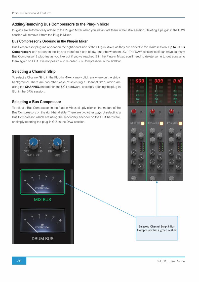
Selecting a Channel StripTo select a Channel Strip in the Plug-in Mixer, simply click anywhere on the strip's
background. There are two other ways of selecting a Channel Strip, which are
using the CHANNEL encoder on the UC1 hardware, or simply opening the plug-in
GUI in the DAW session.
Selecting a Bus CompressorTo select a Bus Compressor in the Plug-in Mixer, simply click on the meters of the
Bus Compressors on the right-hand side. There are two other ways of selecting a
Bus Compressor, which are using the secondary encoder on the UC1 hardware,
or simply opening the plug-in GUI in the DAW session.
Selected Channel Strip & Bus Compressor has a green outline
Product Overview & Features
37SSL UC1 User Guide
Restrictions and Important Notes
Multi-Mono Plug-ins in the Plug-in MixerInstallers for multi-mono Channel Strip 2 and Bus Compressor 2 plug-ins are provided as they always have been with SSL Native
plug-ins. However, it is important to note the following:
Logic - Multi-mono plug-ins are not supported in the Plug-in Mixer - this is because we are currently unable to retreive the DAW
track name.
Pro Tools - Multi-mono plug-ins can be used but control is restricted to the left-hand 'leg' only.
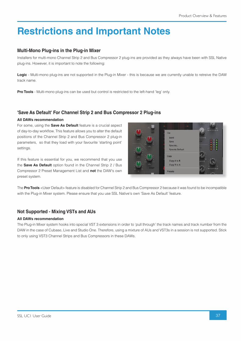
'Save As Default' For Channel Strip 2 and Bus Compressor 2 Plug-insAll DAWs recommendation
For some, using the Save As Default feature is a crucial aspect
of day-to-day workflow. This feature allows you to alter the default
positions of the Channel Strip 2 and Bus Compressor 2 plug-in
parameters, so that they load with your favourite 'starting point'
settings.
If this feature is essential for you, we recommend that you use
the Save As Default option found in the Channel Strip 2 / Bus
Compressor 2 Preset Management List and not the DAW's own
preset system.
The Pro Tools <User Default> feature is disabled for Channel Strip 2 and Bus Compressor 2 because it was found to be incompatible
with the Plug-in Mixer system. Please ensure that you use SSL Native's own 'Save As Default' feature.
Not Supported - Mixing VSTs and AUsAll DAWs recommendation
The Plug-in Mixer system hooks into special VST 3 extensions in order to ‘pull through’ the track names and track number from the
DAW in the case of Cubase, Live and Studio One. Therefore, using a mixture of AUs and VST3s in a session is not supported. Stick
to only using VST3 Channel Strips and Bus Compressors in these DAWs.
Troubleshooting & FAQs
38 SSL UC1 User Guide
UC1 LCD MessagesThe UC1 screen will display various messages:
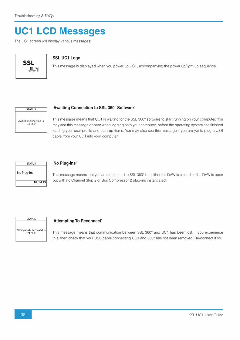
SSL UC1 Logo
This message is displayed when you power up UC1, accompanying the power up/light up sequence.
'Awaiting Connection to SSL 360° Software'
This message means that UC1 is waiting for the SSL 360° software to start running on your computer. You
may see this message appear when logging onto your computer, before the operating system has finished
loading your user-profile and start-up items. You may also see this message if you are yet to plug a USB
cable from your UC1 into your computer.
'No Plug-ins'
This message means that you are connected to SSL 360° but either the DAW is closed or, the DAW is open
but with no Channel Strip 2 or Bus Compressor 2 plug-ins instantiated.
'Attempting To Reconnect'
This message means that communication between SSL 360° and UC1 has been lost. If you experience
this, then check that your USB cable connecting UC1 and 360° has not been removed. Re-connect if so.
Troubleshooting & FAQs
39SSL UC1 User Guide
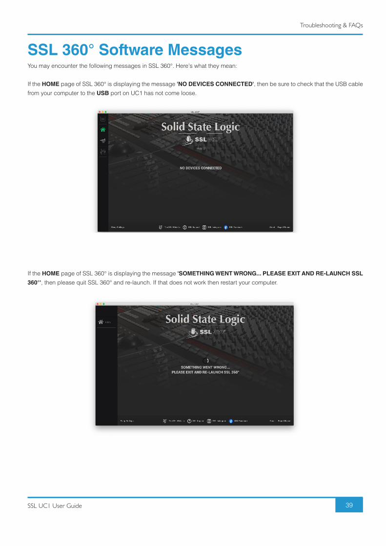
SSL 360° Software MessagesYou may encounter the following messages in SSL 360°. Here's what they mean:
If the HOME page of SSL 360° is displaying the message 'NO DEVICES CONNECTED', then be sure to check that the USB cable
from your computer to the USB port on UC1 has not come loose.
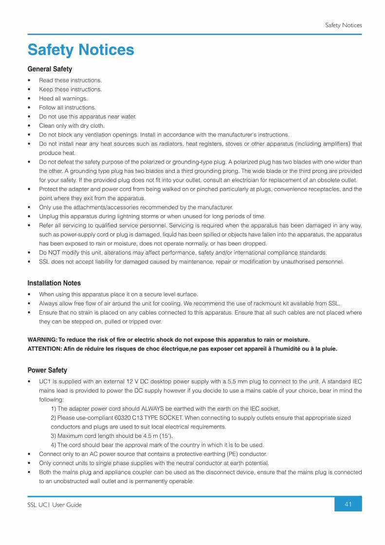
If the HOME page of SSL 360° is displaying the message 'SOMETHING WENT WRONG... PLEASE EXIT AND RE-LAUNCH SSL
360°', then please quit SSL 360° and re-launch. If that does not work then restart your computer.

Troubleshooting & FAQs
40 SSL UC1 User Guide
SSL Support - FAQs, Ask a Question and Compatibility
Visit the Solid State Logic Help Centre to check compatibility with your system and find answers to your questions:
www.solidstatelogic.com/support
Thank youDon’t forget to register your UC1 for the best possible experience.
www.solidstatelogic.com/get-started
Safety Notices
41SSL UC1 User Guide
Safety NoticesGeneral Safety
• Read these instructions.
• Keep these instructions.
• Heed all warnings.
• Follow all instructions.
• Do not use this apparatus near water.
• Clean only with dry cloth.
• Do not block any ventilation openings. Install in accordance with the manufacturer's instructions.
• Do not install near any heat sources such as radiators, heat registers, stoves or other apparatus (including amplifiers) that
produce heat.
• Do not defeat the safety purpose of the polarized or grounding-type plug. A polarized plug has two blades with one wider than
the other. A grounding type plug has two blades and a third grounding prong. The wide blade or the third prong are provided
for your safety. If the provided plug does not fit into your outlet, consult an electrician for replacement of an obsolete outlet.
• Protect the adapter and power cord from being walked on or pinched particularly at plugs, convenience receptacles, and the
point where they exit from the apparatus.
• Only use the attachments/accessories recommended by the manufacturer.
• Unplug this apparatus during lightning storms or when unused for long periods of time.
• Refer all servicing to qualified service personnel. Servicing is required when the apparatus has been damaged in any way,
such as power-supply cord or plug is damaged, liquid has been spilled or objects have fallen into the apparatus, the apparatus
has been exposed to rain or moisture, does not operate normally, or has been dropped.
• Do NOT modify this unit, alterations may affect performance, safety and/or international compliance standards.
• SSL does not accept liability for damaged caused by maintenance, repair or modification by unauthorised personnel.
Installation Notes
• When using this apparatus place it on a secure level surface.
• Always allow free flow of air around the unit for cooling. We recommend the use of rackmount kit available from SSL.
• Ensure that no strain is placed on any cables connected to this apparatus. Ensure that all such cables are not placed where
they can be stepped on, pulled or tripped over.
WARNING: To reduce the risk of fire or electric shock do not expose this apparatus to rain or moisture.
ATTENTION: Afin de réduire les risques de choc électrique,ne pas exposer cet appareil à l'humidité ou à la pluie.
Power Safety
• UC1 is supplied with an external 12 V DC desktop power supply with a 5.5 mm plug to connect to the unit. A standard IEC
mains lead is provided to power the DC supply however if you decide to use a mains cable of your choice, bear in mind the
following:
1) The adapter power cord should ALWAYS be earthed with the earth on the IEC socket.
2) Please use-compliant 60320 C13 TYPE SOCKET. When connecting to supply outlets ensure that appropriate sized
conductors and plugs are used to suit local electrical requirements.
3) Maximum cord length should be 4.5 m (15').
4) The cord should bear the approval mark of the country in which it is to be used.
• Connect only to an AC power source that contains a protective earthing (PE) conductor.
• Only connect units to single phase supplies with the neutral conductor at earth potential.
• Both the mains plug and appliance coupler can be used as the disconnect device, ensure that the mains plug is connected
to an unobstructed wall outlet and is permanently operable.

Safety Notices
42 SSL UC1 User Guide
General Safety
ATTENTION! The desktop power supply must always be earthed. Refer to the User Guide for further details.
CAUTION! No user-serviceable parts inside. In the event of damage to the unit or power supply contact Solid
State Logic. Service or repair must be done by qualified service personnel only.
CE Certification
UC1 is CE compliant. Note that any cables supplied with SSL equipment may be fitted with ferrite rings at each
end. This is to comply with the current regulations and these ferrites should not be removed.
FCC Certification
• Do not modify this unit! The product, when installed as indicated in the instructions contained in the installation manual, meets
FCC requirements.
• Important: This product satisfies FCC regulations when high quality shielded cables are used to connect with other equipment.
Failure to use high quality shielded cables or to follow the installation instructions may cause magnetic interference with
appliances such as radios and televisions and will void your FCC authorisation to use this product in the USA.
• This equipment has been tested and found to comply with the limits for a Class B digital device, pursuant to part 15 of the
FCC Rules. These limits are designed to provide reasonable protection against harmful interference in a residential installation.
This equipment generates, uses and can radiate radio frequency energy and, if not installed and used in accordance with
the instructions, may cause harmful interference to radio communications. However, there is no guarantee that interference
will not occur in a particular installation. If this equipment does cause harmful interference to radio or television reception,
which can be determined by turning the equipment off and on, the user is encourage to try to correct the interference by one
or more of the following measures:
1) Reorient or relocate the receiving antenna.
2) Increase the separation between the equipment and receiver.
3) Connect the equipment into an outlet on a circuit different from that to which the receiver is connected.
4) Consult the dealer or an experienced radio/TV technician for help.
Industry Canada Compliance
This Class B digital apparatus complies with Canadian ICES - 003.
RoHS Notice
Solid State Logic complies with and this product conforms to European Union's Directive 2011/65/EU on Restrictions of Hazardous
Substances (RoHS) as well as the following sections of California law which refer to RoHS, namely sections 25214.10, 25214.10.2,
and 58012, Health and Safety Code; Section 42475.2, Public Resources Code.

Safety Notices
43SSL UC1 User Guide
Instructions for disposal of WEEE by users in the European Union
The symbol shown here, which is on the product or on its packaging, indicates that this product must not be
disposed of with other waste. Instead, it is the user's responsibility to dispose of their waste equipment by
handing it over to a designated collection point for recycling of waste electrical and electronic equipment. The
separate collection and recycling of your waste equipment at the time of disposal will help to conserve natural
resources and ensure that is recycled in a manner that protects human health and the environment. For more
information about where you can drop off your waste equipment for recycling, please contact your local city
office, your household waste disposal service or where you purchased the product.
WARNING: Cancer and Reproductive Harm - www.P65Warnings.ca.gov
Evaluation of apparatus based on altitude not exceeding 2000 m. There may be some potential safety hazard
if the apparatus is operated at altitude exceeding 2000 m.
Evaluation of apparatus based on temperate climate conditions only. There may be some potential safety hazard
if the apparatus is operated in tropical climate conditions.
Electromagnetic Compatibility
EN 55032:2015, Environment: Class B, EN 55103-2:2009, Environments: E1 - E4.
Electrical Safety: UL/IEC 62368-1:2014.
WARNING: Operation of this equipment in a residential environment could causes radio interference.
Environmental
Temperature: Operating: +1 to 30 degrees Celsius. Storage: -20 to 50 degrees Celsius.
Further information
For additional information, install and user guides, knowledge base and technical support visit www.solidstatelogic.com
SSL UC1
www.solidstatelogic.com