Embed Size (px)
Citation preview

Project Manual
St. Martin's Home
Lobby Renovations and Canopy
Addition
Little Sisters of the Poor
601 Maiden Choice Lane
Baltimore, Maryland 21228 Project Number: 17000.00
Date: May 11, 2017
810 Light Street Baltimore, Maryland 21230 (410) 837-5040

Gaudreau, Inc. Renovations to St. Martin’s Home – Lobby/Entry Baltimore, MD Little Sisters of the Poor Project No. 17000.01 Baltimore, MD
CONTRACT MODIFICATION PROCEDURES 012600 - 1
SECTION 012600
CONTRACT MODIFICATION PROCEDURES
PART 1 - GENERAL
1.1 RELATED DOCUMENTS
A. Drawings and general provisions of the Contract, including General and Supplementary Conditions and other Division 01 Specification Sections, apply to this Section.
1.2 SUMMARY
A. Section includes administrative and procedural requirements for handling and processing Contract modifications.
B. Related Sections:
1. Division 01 Section "Product Requirements" for administrative procedures for handling requests for substitutions made after Contract award.
1.3 MINOR CHANGES IN THE WORK
A. Architect will issue supplemental instructions authorizing minor changes in the Work, not involving adjustment to the Contract Sum or the Contract Time, on AIA Document G710, "Architect's Supplemental Instructions."
1.4 PROPOSAL REQUESTS
A. Owner-Initiated Proposal Requests: Architect will issue a detailed description of proposed changes in the Work that may require adjustment to the Contract Sum or the Contract Time. If necessary, the description will include supplemental or revised Drawings and Specifications.
1. Proposal Requests issued by Architect are not instructions either to stop work in progress or to execute the proposed change.
2. Within 20 days, when not otherwise specified, after receipt of Proposal Request, submit a quotation estimating cost adjustments to the Contract Sum and the Contract Time necessary to execute the change.
a. Include a list of quantities of products required or eliminated and unit costs, with total amount of purchases and credits to be made. If requested, furnish survey data to substantiate quantities.
b. Indicate applicable taxes, delivery charges, equipment rental, and amounts of trade discounts.
c. Include costs of labor and supervision directly attributable to the change. d. Include an updated Contractor's construction schedule that indicates the effect of
the change, including, but not limited to, changes in activity duration, start and
Gaudreau, Inc. Renovations to St. Martin’s Home – Lobby/Entry Baltimore, MD Little Sisters of the Poor Project No. 17000.01 Baltimore, MD
CONTRACT MODIFICATION PROCEDURES 012600 - 2
finish times, and activity relationship. Use available total float before requesting an extension of the Contract Time.
e. Quotation Form: Use CSI Form 13.6B "Proposal Worksheet Summary" and 13.6C "Proposal Worksheet Detail".
B. Contractor-Initiated Proposals: If latent or changed conditions require modifications to the Contract, Contractor may initiate a claim by submitting a request for a change to Architect.
1. Include a statement outlining reasons for the change and the effect of the change on the Work. Provide a complete description of the proposed change. Indicate the effect of the proposed change on the Contract Sum and the Contract Time.
2. Include a list of quantities of products required or eliminated and unit costs, with total amount of purchases and credits to be made. If requested, furnish survey data to substantiate quantities.
3. Indicate applicable taxes, delivery charges, equipment rental, and amounts of trade discounts.
4. Include costs of labor and supervision directly attributable to the change. 5. Include an updated Contractor's construction schedule that indicates the effect of the
change, including, but not limited to, changes in activity duration, start and finish times, and activity relationship. Use available total float before requesting an extension of the Contract Time.
6. Comply with requirements in Division 01 Section "Substitution Procedures" if the proposed change requires substitution of one product or system for product or system specified.
7. Proposal Request Form: Use CSI Form 13.6A "Change Order Request (Proposal)" with attachments CSI Form 13.6B "Proposal Worksheet Summary" and 13.6C "Proposal Worksheet Detail".
1.5 CHANGE ORDER PROCEDURES
A. On Owner's approval of a Proposal Request, Architect will issue a Change Order for signatures of Owner and Contractor on AIA Document G701.
1.6 CONSTRUCTION CHANGE DIRECTIVE
1. Work Change Directive: Architect may issue a Work Change Directive on AIA Document G714. Work Change Directive instructs Contractor to proceed with a change in the Work, for subsequent inclusion in a Change Order.
2. Work Change Directive contains a complete description of change in the Work. It also designates method to be followed to determine change in the Contract Sum or the Contract Time.
B. Documentation: Maintain detailed records on a time and material basis of work required by the Work Change Directive.
1. After completion of change, submit an itemized account and supporting data necessary to substantiate cost and time adjustments to the Contract.
PART 2 - PRODUCTS (Not Used)

Gaudreau, Inc. Renovations to St. Martin’s Home – Lobby/Entry Baltimore, MD Little Sisters of the Poor Project No. 17000.01 Baltimore, MD
CONTRACT MODIFICATION PROCEDURES 012600 - 3
PART 3 - EXECUTION (Not Used)
END OF SECTION

Gaudreau, Inc. Renovations to St. Martin’s Home – Lobby/Entry Baltimore, MD Little Sisters of the Poor Project No. 17000.01 Baltimore, MD
PROJECT MANAGEMENT AND COORDINATION 013100 - 1
SECTION 013100
PROJECT MANAGEMENT AND COORDINATION
PART 1 - GENERAL
1.1 RELATED DOCUMENTS
A. Drawings and general provisions of the Contract, including General and Supplementary Conditions and other Division 01 Specification Sections, apply to this Section.
1.2 SUMMARY
A. This Section includes administrative provisions for coordinating construction operations on Project including, but not limited to, the following:
1. Coordination Drawings. 2. Administrative and supervisory personnel. 3. Project meetings. 4. Requests for Interpretation (RFIs).
B. Related Sections include the following:
1. Division 01 Section "Summary" for a description of the Work. 2. Division 01 Section "Construction Progress Documentation" for preparing and submitting
Contractor's Construction Schedule. 3. Division 01 Section "Execution Requirements" for procedures for coordinating general
installation and field-engineering services, including establishment of benchmarks and control points.
4. Division 01 Section "Closeout Procedures" for coordinating closeout of the Contract.
1.3 DEFINITIONS
A. RFI: Request from Contractor seeking interpretation or clarification of the Contract Documents.
1.4 COORDINATION
A. Coordination: Coordinate construction operations included in different Sections of the Specifications to ensure efficient and orderly installation of each part of the Work. Coordinate construction operations, included in different Sections that depend on each other for proper installation, connection, and operation.
1. Schedule construction operations in sequence required to obtain the best results where installation of one part of the Work depends on installation of other components, before or after its own installation.
2. Coordinate installation of different components with other contractors to ensure maximum accessibility for required maintenance, service, and repair.
3. Make adequate provisions to accommodate items scheduled for later installation.
Gaudreau, Inc. Renovations to St. Martin’s Home – Lobby/Entry Baltimore, MD Little Sisters of the Poor Project No. 17000.01 Baltimore, MD
PROJECT MANAGEMENT AND COORDINATION 013100 - 2
4. Where availability of space is limited, coordinate installation of different components to ensure maximum performance and accessibility for required maintenance, service, and repair of all components, including mechanical and electrical.
B. Prepare memoranda for distribution to each party involved, outlining special procedures required for coordination. Include such items as required notices, reports, and list of attendees at meetings.
1. Prepare similar memoranda for Owner and separate contractors if coordination of their Work is required.
C. Administrative Procedures: Coordinate scheduling and timing of required administrative procedures with other construction activities and activities of other contractors to avoid conflicts and to ensure orderly progress of the Work. Such administrative activities include, but are not limited to, the following:
1. Preparation of Contractor's Construction Schedule. 2. Preparation of the Schedule of Values. 3. Installation and removal of temporary facilities and controls. 4. Delivery and processing of submittals. 5. Progress meetings. 6. Preinstallation conferences. 7. Project closeout activities. 8. Startup and adjustment of systems. 9. Project closeout activities.
D. Conservation: Coordinate construction activities to ensure that operations are carried out with consideration given to conservation of energy, water, and materials.
1. Salvage materials and equipment involved in performance of, but not actually incorporated into, the Work. Refer to other Sections for disposition of salvaged materials that are designated as Owner's property.
1.5 COORDINATION DRAWINGS
A. Coordination Drawings: Prepare Coordination Drawings if limited space availability necessitates maximum utilization of space for efficient installation of different components or if coordination is required for installation of products and materials fabricated by separate entities.
1. Content: Project-specific information, drawn accurately to scale. Do not base Coordination Drawings on reproductions of the Contract Documents or standard printed data. Include the following information, as applicable:
a. Use applicable Drawings as a basis for preparation of coordination drawings. Prepare sections, elevations, and details as needed to describe relationship of various systems and components.
b. Indicate functional and spatial relationships of components of architectural, structural, civil, mechanical, and electrical systems.
c. Indicate required installation sequences. d. Indicate space requirements for routine maintenance and for anticipated
replacement of components during the life of the installation. e. Show location and size of access doors required for access to concealed dampers,
valves, and other controls.

Gaudreau, Inc. Renovations to St. Martin’s Home – Lobby/Entry Baltimore, MD Little Sisters of the Poor Project No. 17000.01 Baltimore, MD
PROJECT MANAGEMENT AND COORDINATION 013100 - 3
f. Indicate dimensions shown on the Contract Drawings and make specific note of dimensions that appear to be in conflict with submitted equipment and minimum clearance requirements. Provide alternate sketches to Architect for resolution of such conflicts. Minor dimension changes and difficult installations will not be considered changes to the Contract.
2. Sheet Size: At least 8-1/2 by 11 inches but no larger than 24 by 36 inches. 3. Number of Copies: Submit five opaque copies of each submittal. Architect will return
four copies.
a. Submit five copies where Coordination Drawings are required for operation and maintenance manuals. Architect will retain one copy; remainder will be returned. Mark up and retain one returned copy as a Project Record Drawing.
4. Refer to individual Sections for Coordination Drawing requirements for Work in those Sections.
B. Key Personnel Names: Within 15 days of starting construction operations, submit a list of key personnel assignments, including superintendent and other personnel in attendance at Project site. Identify individuals and their duties and responsibilities; list addresses and telephone numbers, including home and office telephone numbers. Provide names, addresses, and telephone numbers of individuals assigned as standbys in the absence of individuals assigned to Project.
1. Post copies of list in Project meeting room, in temporary field office, and by each temporary telephone. Keep list current at all times.
1.6 KEY PERSONNEL
A. Key Personnel Names: Within 15 days of starting construction operations, submit a list of key personnel assignments, including superintendent and other personnel in attendance at Project site. Identify individuals and their duties and responsibilities; list addresses and telephone numbers, including home, office, and cellular telephone numbers and email addresses. Provide names, addresses, and telephone numbers of individuals assigned as standbys in the absence of individuals assigned to Project.
1. Post copies of list in project meeting room, in temporary field office, and by each temporary telephone. Keep list current at all times.
1.7 PROJECT MEETINGS
A. General: Schedule and conduct meetings and conferences at Project site unless otherwise indicated.
1. Attendees: Inform participants and others involved, and individuals whose presence is required, of date and time of each meeting. Notify Owner and Architect of scheduled meeting dates and times.
2. Agenda: Prepare the meeting agenda. Distribute the agenda to all invited attendees. 3. Minutes: Record significant discussions and agreements achieved. Distribute the
meeting minutes to everyone concerned, including Owner and Architect, within three days of the meeting.

Gaudreau, Inc. Renovations to St. Martin’s Home – Lobby/Entry Baltimore, MD Little Sisters of the Poor Project No. 17000.01 Baltimore, MD
PROJECT MANAGEMENT AND COORDINATION 013100 - 4
B. Preconstruction Conference: Schedule a preconstruction conference before starting construction, at a time convenient to Owner, and Architect, but no later than 15 days after execution of the Agreement. Hold the conference at Project site or another convenient location. Conduct the meeting to review responsibilities and personnel assignments.
1. Attendees: Authorized representatives of Owner, Architect, and their consultants; Contractor and its superintendent; major subcontractors; suppliers; and other concerned parties shall attend the conference. All participants at the conference shall be familiar with Project and authorized to conclude matters relating to the Work.
2. Agenda: Discuss items of significance that could affect progress, including the following:
a. Tentative construction schedule. b. Phasing. c. Critical work sequencing and long-lead items. d. Designation of key personnel and their duties. e. Procedures for processing field decisions and Change Orders. f. Procedures for RFIs. g. Procedures for testing and inspecting. h. Procedures for processing Applications for Payment. i. Distribution of the Contract Documents. j. Submittal procedures. k. Preparation of Record Documents. l. Use of the premises. m. Work restrictions. n. Owner's occupancy requirements. o. Responsibility for temporary facilities and controls. p. Construction waste management and recycling. q. Parking availability. r. Office, work, and storage areas. s. Equipment deliveries and priorities. t. First aid. u. Security. v. Progress cleaning. w. Working hours.
3. Minutes: Contractor will record and distribute meeting minutes.
C. Preinstallation Conferences: Conduct a preinstallation conference at Project site before each construction activity that requires coordination with other construction.
1. Attendees: Installer and representatives of manufacturers and fabricators involved in or affected by the installation and its coordination or integration with other materials and installations that have preceded or will follow, shall attend the meeting. Advise Architect and Construction Manager of scheduled meeting dates.
2. Agenda: Review progress of other construction activities and preparations for the particular activity under consideration, including requirements for the following:
a. The Contract Documents. b. Options. c. Related RFIs. d. Related Change Orders. e. Purchases. f. Deliveries. g. Submittals. h. Review of mockups.

Gaudreau, Inc. Renovations to St. Martin’s Home – Lobby/Entry Baltimore, MD Little Sisters of the Poor Project No. 17000.01 Baltimore, MD
PROJECT MANAGEMENT AND COORDINATION 013100 - 5
i. Possible conflicts. j. Compatibility problems. k. Time schedules. l. Weather limitations. m. Manufacturer's written recommendations. n. Warranty requirements. o. Compatibility of materials. p. Acceptability of substrates. q. Temporary facilities and controls. r. Space and access limitations. s. Regulations of authorities having jurisdiction. t. Testing and inspecting requirements. u. Installation procedures. v. Coordination with other work. w. Required performance results. x. Protection of adjacent work. y. Protection of construction and personnel.
3. Record significant conference discussions, agreements, and disagreements, including required corrective measures and actions.
4. Reporting: Distribute minutes of the meeting to each party present and to parties who should have been present.
5. Do not proceed with installation if the conference cannot be successfully concluded. Initiate whatever actions are necessary to resolve impediments to performance of the Work and reconvene the conference at earliest feasible date.
D. Progress Meetings: Conduct progress meetings at biweekly intervals. Coordinate dates of meetings with preparation of payment requests.
1. Attendees: In addition to representatives of Owner, and Architect, each contractor, subcontractor, supplier, and other entity concerned with current progress or involved in planning, coordination, or performance of future activities shall be represented at these meetings. All participants at the conference shall be familiar with Project and authorized to conclude matters relating to the Work.
2. Agenda: Review and correct or approve minutes of previous progress meeting. Review other items of significance that could affect progress. Include topics for discussion as appropriate to status of Project.
a. Contractor's Construction Schedule: Review progress since the last meeting. Determine whether each activity is on time, ahead of schedule, or behind schedule, in relation to Contractor's Construction Schedule. Determine how construction behind schedule will be expedited; secure commitments from parties involved to do so. Discuss whether schedule revisions are required to ensure that current and subsequent activities will be completed within the Contract Time.
1) Review schedule for next period.
b. Review present and future needs of each entity present, including the following:
1) Interface requirements. 2) Sequence of operations. 3) Status of submittals. 4) Deliveries. 5) Off-site fabrication. 6) Access.

Gaudreau, Inc. Renovations to St. Martin’s Home – Lobby/Entry Baltimore, MD Little Sisters of the Poor Project No. 17000.01 Baltimore, MD
PROJECT MANAGEMENT AND COORDINATION 013100 - 6
7) Site utilization. 8) Temporary facilities and controls. 9) Work hours. 10) Hazards and risks. 11) Progress cleaning. 12) Quality and work standards. 13) Status of correction of deficient items. 14) Field observations. 15) RFIs. 16) Status of proposal requests. 17) Pending changes. 18) Status of Change Orders. 19) Pending claims and disputes. 20) Documentation of information for payment requests.
3. Minutes: Contractor will record and distribute to Architect the meeting minutes. 4. Reporting: Distribute minutes of the meeting to each party present and to parties who
should have been present.
a. Schedule Updating: Revise Contractor's Construction Schedule after each progress meeting where revisions to the schedule have been made or recognized. Issue revised schedule concurrently with the report of each meeting.
E. Coordination Meetings: Conduct Project coordination meetings at biweekly intervals. Project coordination meetings are in addition to specific meetings held for other purposes, such as progress meetings and preinstallation conferences.
1. Attendees: In addition to representatives of Owner, Construction Manager and Architect, each contractor, subcontractor, supplier, and other entity concerned with current progress or involved in planning, coordination, or performance of future activities shall be represented at these meetings. All participants at the conference shall be familiar with Project and authorized to conclude matters relating to the Work.
2. Agenda: Review and correct or approve minutes of the previous coordination meeting. Review other items of significance that could affect progress. Include topics for discussion as appropriate to status of Project.
a. Combined Contractor's Construction Schedule: Review progress since the last coordination meeting. Determine whether each contract is on time, ahead of schedule, or behind schedule, in relation to Combined Contractor's Construction Schedule. Determine how construction behind schedule will be expedited; secure commitments from parties involved to do so. Discuss whether schedule revisions are required to ensure that current and subsequent activities will be completed within the Contract Time.
b. Schedule Updating: Revise Combined Contractor's Construction Schedule after each coordination meeting where revisions to the schedule have been made or recognized. Issue revised schedule concurrently with report of each meeting.
c. Review present and future needs of each contractor present, including the following:
1) Interface requirements. 2) Sequence of operations. 3) Status of submittals. 4) Deliveries. 5) Off-site fabrication. 6) Access.
Gaudreau, Inc. Renovations to St. Martin’s Home – Lobby/Entry Baltimore, MD Little Sisters of the Poor Project No. 17000.01 Baltimore, MD
PROJECT MANAGEMENT AND COORDINATION 013100 - 7
7) Site utilization. 8) Temporary facilities and controls. 9) Work hours. 10) Hazards and risks. 11) Progress cleaning. 12) Quality and work standards. 13) Change Orders.
3. Reporting: Record meeting results and distribute copies to everyone in attendance and to others affected by decisions or actions resulting from each meeting.
1.8 REQUESTS FOR INTERPRETATION (RFIs)
A. Procedure: Immediately on discovery of the need for interpretation of the Contract Documents, and if not possible to request interpretation at Project meeting, prepare and submit an RFI in the form specified.
1. RFIs shall originate with Contractor. RFIs submitted by entities other than Contractor will be returned with no response.
2. Coordinate and submit RFIs in a prompt manner so as to avoid delays in Contractor's work or work of subcontractors.
B. Content of the RFI: Include a detailed, legible description of item needing interpretation and the following:
1. Project name. 2. Date. 3. Name of Contractor. 4. Name of Architect. 5. RFI number, numbered sequentially. 6. Specification Section number and title and related paragraphs, as appropriate. 7. Drawing number and detail references, as appropriate. 8. Field dimensions and conditions, as appropriate. 9. Contractor's suggested solution(s). If Contractor's solution(s) impact the Contract Time
or the Contract Sum, Contractor shall state impact in the RFI. 10. Contractor's signature. 11. Attachments: Include drawings, descriptions, measurements, photos, Product Data,
Shop Drawings, and other information necessary to fully describe items needing interpretation.
a. Supplementary drawings prepared by Contractor shall include dimensions, thicknesses, structural grid references, and details of affected materials, assemblies, and attachments.
C. Hard-Copy RFIs: CSI Form 13.2A.
1. Identify each page of attachments with the RFI number and sequential page number.
D. Software-Generated RFIs: Software-generated form with substantially the same content as indicated above.
1. Attachments shall be electronic files in Adobe Acrobat PDF format.

Gaudreau, Inc. Renovations to St. Martin’s Home – Lobby/Entry Baltimore, MD Little Sisters of the Poor Project No. 17000.01 Baltimore, MD
PROJECT MANAGEMENT AND COORDINATION 013100 - 8
E. Architect's Action: Architect will review each RFI, determine action required, and return it. Allow seven working days for Architect's response for each RFI. RFIs received after 1:00 p.m. will be considered as received the following working day.
1. The following RFIs will be returned without action:
a. Requests for approval of submittals. b. Requests for approval of substitutions. c. Requests for coordination information already indicated in the Contract
Documents. d. Requests for adjustments in the Contract Time or the Contract Sum. e. Requests for interpretation of Architect's actions on submittals. f. Incomplete RFIs or RFIs with numerous errors.
2. Architect's action may include a request for additional information, in which case Architect's time for response will start again.
3. Architect's action on RFIs that may result in a change to the Contract Time or the Contract Sum may be eligible for Contractor to submit Change Proposal according to Division 1 Section "Contract Modification Procedures."
a. If Contractor believes the RFI response warrants change in the Contract Time or the Contract Sum, notify Architect and Construction Manager in writing within 10 days of receipt of the RFI response.
F. On receipt of Architect's action, update the RFI log and immediately distribute the RFI response to affected parties. Review response and notify Architect and Construction Manager within seven days if Contractor disagrees with response.
G. RFI Log: Prepare, maintain, and submit a tabular log of RFIs organized by the RFI number. Submit log weekly. Use CSI Log Form 13.2B.
1. Identification of related Minor Change in the Work, Construction Change Directive, and Proposal Request, as appropriate.
2. Identification of related Field Order, Work Change Directive, and Proposal Request, as appropriate.
PART 2 - PRODUCTS (Not Used)
PART 3 - EXECUTION (Not Used)
END OF SECTION

Gaudreau, Inc. Renovations to St. Martin’s Home – Lobby/Entry Baltimore, MD Little Sisters of the Poor Project No. 17000.01 Baltimore, MD
SUBMITTAL PROCEDURES 013300 - 1
SECTION 013300
SUBMITTAL PROCEDURES
PART 1 - GENERAL
1.1 RELATED DOCUMENTS
A. Drawings and general provisions of the Contract, including General and Supplementary Conditions and other Division 01 Specification Sections, apply to this Section.
1.2 SUMMARY
A. This Section includes administrative and procedural requirements for submitting Shop Drawings, Product Data, Samples, and other submittals.
B. Related Sections:
1. See Division 01 Section "Construction Progress Documentation" for submitting schedules and reports, including Contractor's Construction Schedule.
2. See Division 01 Section "Closeout Procedures" for submitting warranties. 3. See Division 01 Section "Project Record Documents" for submitting Record Drawings,
Record Specifications, and Record Product Data. 4. See Division 01 Section "Operation and Maintenance Data" for submitting operation and
maintenance manuals.
1.3 DEFINITIONS
A. Action Submittals: Written and graphic information that requires Architect's and Contractor's responsive action.
B. Informational Submittals: Written information that does not require Architect's and Construction Manager’s responsive action. Submittals may be rejected for not complying with requirements.
1.4 SUBMITTAL PROCEDURES
A. Coordination: Coordinate preparation and processing of submittals with performance of construction activities.
1. Coordinate each submittal with fabrication, purchasing, testing, delivery, other submittals, and related activities that require sequential activity.
2. Coordinate transmittal of different types of submittals for related parts of the Work so processing will not be delayed because of need to review submittals concurrently for coordination.
a. Architect reserves the right to withhold action on a submittal requiring coordination with other submittals until related submittals are received.

Gaudreau, Inc. Renovations to St. Martin’s Home – Lobby/Entry Baltimore, MD Little Sisters of the Poor Project No. 17000.01 Baltimore, MD
SUBMITTAL PROCEDURES 013300 - 2
B. Submittals Schedule: Comply with requirements in Division 01 Section "Construction Progress Documentation" for list of submittals and time requirements for scheduled performance of related construction activities.
C. Processing Time: Allow enough time for submittal review, including time for resubmittals, as follows. Time for review shall commence on Architect's receipt of submittal. No extension of the Contract Time will be authorized because of failure to transmit submittals enough in advance of the Work to permit processing, including resubmittals.
1. Initial Review: Allow 10 days for initial review of each submittal. Allow additional time if coordination with subsequent submittals is required. Architect will advise Contractor when a submittal being processed must be delayed for coordination.
2. Intermediate Review: If intermediate submittal is necessary, process it in same manner as initial submittal.
3. Resubmittal Review: Allow 10 days for review of each resubmittal.
D. Identification: Place a permanent label or title block on each submittal for identification.
1. Indicate name of firm or entity that prepared each submittal on label or title block. 2. Provide a space approximately 6 by 8 inches on label or beside title block to record
Contractor's review and approval markings and action taken by Architect. 3. Include the following information on label for processing and recording action taken:
a. Project name. b. Date. c. Name and address of Architect. d. Name and address of Contractor. e. Name and address of subcontractor. f. Name and address of supplier. g. Name of manufacturer. h. Submittal number or other unique identifier, including revision identifier.
1) Submittal number shall use Specification Section number followed by a decimal point and then a sequential number (e.g., 06100.01). Resubmittals shall include an alphabetic suffix after another decimal point (e.g., 06100.01.A).
i. Number and title of appropriate Specification Section. j. Drawing number and detail references, as appropriate. k. Location(s) where product is to be installed, as appropriate. l. Other necessary identification.
E. Deviations: Highlight, encircle, or otherwise specifically identify deviations from the Contract Documents on submittals.
F. Additional Copies: Unless additional copies are required for final submittal, and unless Architect observes noncompliance with provisions in the Contract Documents, initial submittal may serve as final submittal.
1. Additional copies submitted for maintenance manuals will not be marked with action taken and will be returned.
G. Transmittal: Package each submittal individually and appropriately for transmittal and handling. Transmit each submittal using a transmittal form. Architect and Contractor will return submittals, without review, received from sources other than Contractor.
Gaudreau, Inc. Renovations to St. Martin’s Home – Lobby/Entry Baltimore, MD Little Sisters of the Poor Project No. 17000.01 Baltimore, MD
SUBMITTAL PROCEDURES 013300 - 3
1. Transmittal Form: Use AIA Document G810.
H. Resubmittals: Make resubmittals in same form and number of copies as initial submittal.
1. Note date and content of previous submittal. 2. Note date and content of revision in label or title block and clearly indicate extent of
revision. 3. Resubmit submittals until they are marked "No exceptions taken” Insert approval notation
from Architect's and Contractor's action stamp."
I. Distribution: Furnish copies of final submittals to manufacturers, subcontractors, suppliers, fabricators, installers, authorities having jurisdiction, and others as necessary for performance of construction activities. Show distribution on transmittal forms.
J. Use for Construction: Use only final submittals with mark indicating "No exceptions taken”. Insert approval notation from Architect's and Construction Manager’s action stamp" taken by Architect and Contractor.
1.5 CONTRACTOR'S USE OF ARCHITECT'S CAD FILES
A. General: At Contractor's written request, copies of Architect's CAD files will be provided to Contractor for Contractor's use in connection with Project, subject to the following conditions:
1. Architect will provide electronic copies of CAD drawings of the Contract Documents, at the discretion of the county, for Contractors use in preparing submittals upon execution of release form.
2. CAD file availability will be limited to plan related Drawings only.
PART 2 - PRODUCTS
2.1 ACTION SUBMITTALS
A. General: Prepare and submit Action Submittals required by individual Specification Sections.
B. Product Data: Collect information into a single submittal for each element of construction and type of product or equipment.
1. If information must be specially prepared for submittal because standard printed data are not suitable for use, submit as Shop Drawings, not as Product Data.
2. Mark each copy of each submittal to show which products and options are applicable. 3. Include the following information, as applicable:
a. Manufacturer's written recommendations. b. Manufacturer's product specifications. c. Manufacturer's installation instructions. d. Manufacturer's catalog cuts. e. Wiring diagrams showing factory-installed wiring. f. Printed performance curves. g. Operational range diagrams. h. Compliance with specified referenced standards. i. Testing by recognized testing agency.
Gaudreau, Inc. Renovations to St. Martin’s Home – Lobby/Entry Baltimore, MD Little Sisters of the Poor Project No. 17000.01 Baltimore, MD
SUBMITTAL PROCEDURES 013300 - 4
4. Number of Copies: Submit sufficient copies to provide for the retention by the Architect and Owner five (5) copies total plus such additional copies as the Contractor may require.
C. Shop Drawings: Prepare Project-specific information, drawn accurately to scale. Do not base Shop Drawings on reproductions of the Contract Documents or standard printed data, unless submittal of Architect's CAD Drawings is otherwise permitted.
1. Preparation: Fully illustrate requirements in the Contract Documents. Include the following information, as applicable:
a. Dimensions. b. Identification of products. c. Fabrication and installation drawings. d. Roughing-in and setting diagrams. e. Wiring diagrams showing field-installed wiring, including power, signal, and control
wiring. f. Shopwork manufacturing instructions. g. Templates and patterns. h. Schedules. i. Notation of coordination requirements. j. Notation of dimensions established by field measurement. k. Relationship to adjoining construction clearly indicated. l. Seal and signature of professional engineer if specified. m. Wiring Diagrams: Differentiate between manufacturer-installed and field-installed
wiring.
2. Sheet Size: Except for templates, patterns, and similar full-size drawings, submit Shop Drawings on sheets at least 8-1/2 by 11 inches but no larger than 30 by 42 inches.
3. Number of Copies: Submit sufficient copies to provide for the retention by the Architect and Owner five (5) copies total plus such additional copies as the Contractor may require.
D. Samples: Submit Samples for review of kind, color, pattern, and texture for a check of these characteristics with other elements and for a comparison of these characteristics between submittal and actual component as delivered and installed.
1. Transmit Samples that contain multiple, related components such as accessories together in one submittal package.
2. Identification: Attach label on unexposed side of Samples that includes the following:
a. Generic description of Sample. b. Product name and name of manufacturer. c. Sample source. d. Number and title of appropriate Specification Section.
3. Disposition: Maintain sets of approved Samples at Project site, available for quality-control comparisons throughout the course of construction activity. Sample sets may be used to determine final acceptance of construction associated with each set.
4. Samples for Initial Selection: Submit manufacturer's color charts consisting of units or sections of units showing the full range of colors, textures, and patterns available.
a. Number of Samples: Submit one full set(s) of available choices where color, pattern, texture, or similar characteristics are required to be selected from manufacturer's product line. Architect will return submittal with options selected.

Gaudreau, Inc. Renovations to St. Martin’s Home – Lobby/Entry Baltimore, MD Little Sisters of the Poor Project No. 17000.01 Baltimore, MD
SUBMITTAL PROCEDURES 013300 - 5
5. Samples for Verification: Submit full-size units or Samples of size indicated, prepared from same material to be used for the Work, cured and finished in manner specified, and physically identical with material or product proposed for use, and that show full range of color and texture variations expected. Samples include, but are not limited to, the following: partial sections of manufactured or fabricated components; small cuts or containers of materials; complete units of repetitively used materials; swatches showing color, texture, and pattern; color range sets; and components used for independent testing and inspection.
a. Number of Samples: Submit four sets of Samples. Architect will retain two Sample sets; remainder will be returned. Mark up and retain one returned Sample set as a Project Record Sample.
E. Product Schedule or List: As required in individual Specification Sections, prepare a written summary indicating types of products required for the Work and their intended location.
1. Number of Copies: Submit three copies of product schedule or list, unless otherwise indicated. Architect through Construction Manager will return two copies.
F. Submittals Schedule: Comply with requirements specified in Division 1 Section "Construction Progress Documentation."
G. Application for Payment: Comply with requirements specified in Division 1 Section "Payment Procedures."
H. Schedule of Values: Comply with requirements specified in Division 1 Section "Payment Procedures."
I. Subcontract List: Prepare a written summary identifying individuals or firms proposed for each portion of the Work, including those who are to furnish products or equipment fabricated to a special design. Use CSI Form 1.5A.
1. Number of Copies: Submit three copies of subcontractor list, unless otherwise indicated. Architect will return two copies.
2.2 INFORMATIONAL SUBMITTALS
A. General: Prepare and submit Informational Submittals required by other Specification Sections.
1. Number of Copies: Submit sufficient copies to provide for the retention by the Architect and Owner five (5) copies total plus such additional copies as the Contractor may require.
2. Certificates and Certifications: Provide a notarized statement that includes signature of entity responsible for preparing certification. Certificates and certifications shall be signed by an officer or other individual authorized to sign documents on behalf of that entity.
3. Test and Inspection Reports: Comply with requirements specified in Division 1 Section "Quality Requirements."
B. Coordination Drawings: Comply with requirements specified in Division 1 Section "Project Management and Coordination."
C. Contractor's Construction Schedule: Comply with requirements specified in Division 1 Section "Construction Progress Documentation" for Contractor’s action.

Gaudreau, Inc. Renovations to St. Martin’s Home – Lobby/Entry Baltimore, MD Little Sisters of the Poor Project No. 17000.01 Baltimore, MD
SUBMITTAL PROCEDURES 013300 - 6
D. Qualification Data: Prepare written information that demonstrates capabilities and experience of firm or person. Include lists of completed projects with project names and addresses, names and addresses of architects and owners, and other information specified.
E. Welding Certificates: Prepare written certification that welding procedures and personnel comply with requirements in the Contract Documents. Submit record of Welding Procedure Specification (WPS) and Procedure Qualification Record (PQR) on AWS forms. Include names of firms and personnel certified.
F. Installer Certificates: Prepare written statements on manufacturer's letterhead certifying that Installer complies with requirements in the Contract Documents and, where required, is authorized by manufacturer for this specific Project.
G. Manufacturer Certificates: Prepare written statements on manufacturer's letterhead certifying that manufacturer complies with requirements in the Contract Documents. Include evidence of manufacturing experience where required.
H. Product Certificates: Prepare written statements on manufacturer's letterhead certifying that product complies with requirements in the Contract Documents.
I. Material Certificates: Prepare written statements on manufacturer's letterhead certifying that material complies with requirements in the Contract Documents.
J. Material Test Reports: Prepare reports written by a qualified testing agency, on testing agency's standard form, indicating and interpreting test results of material for compliance with requirements in the Contract Documents.
K. Product Test Reports: Prepare written reports indicating current product produced by manufacturer complies with requirements in the Contract Documents. Base reports on evaluation of tests performed by manufacturer and witnessed by a qualified testing agency, or on comprehensive tests performed by a qualified testing agency.
L. Research/Evaluation Reports: Prepare written evidence, from a model code organization acceptable to authorities having jurisdiction, that product complies with building code in effect for Project.
M. Preconstruction Test Reports: Prepare reports written by a qualified testing agency, on testing agency's standard form, indicating and interpreting results of tests performed before installation of product, for compliance with performance requirements in the Contract Documents.
N. Compatibility Test Reports: Prepare reports written by a qualified testing agency, on testing agency's standard form, indicating and interpreting results of compatibility tests performed before installation of product. Include written recommendations for primers and substrate preparation needed for adhesion.
O. Field Test Reports: Prepare reports written by a qualified testing agency, on testing agency's standard form, indicating and interpreting results of field tests performed either during installation of product or after product is installed in its final location, for compliance with requirements in the Contract Documents.
P. Maintenance Data: Prepare written and graphic instructions and procedures for operation and normal maintenance of products and equipment. Comply with requirements specified in Division 1 Section "Operation and Maintenance Data."

Gaudreau, Inc. Renovations to St. Martin’s Home – Lobby/Entry Baltimore, MD Little Sisters of the Poor Project No. 17000.01 Baltimore, MD
SUBMITTAL PROCEDURES 013300 - 7
Q. Design Data: Prepare written and graphic information, including, but not limited to, performance and design criteria, list of applicable codes and regulations, and calculations. Include list of assumptions and other performance and design criteria and a summary of loads. Include load diagrams if applicable. Provide name and version of software, if any, used for calculations. Include page numbers.
R. Manufacturer's Instructions: Prepare written or published information that documents manufacturer's recommendations, guidelines, and procedures for installing or operating a product or equipment. Include name of product and name, address, and telephone number of manufacturer.
S. Manufacturer's Field Reports: Prepare written information documenting factory-authorized service representative's tests and inspections. Include the following, as applicable:
1. Statement on condition of substrates and their acceptability for installation of product. 2. Summary of installation procedures being followed, whether they comply with
requirements and, if not, what corrective action was taken. 3. Results of operational and other tests and a statement of whether observed performance
complies with requirements.
T. Insurance Certificates and Bonds: Prepare written information indicating current status of insurance or bonding coverage. Include name of entity covered by insurance or bond, limits of coverage, amounts of deductibles, if any, and term of the coverage.
U. Construction Photographs: Comply with requirements specified in Division 1 Section "Photographic Documentation."
V. Material Safety Data Sheets (MSDSs): Submit information directly to Owner; do not submit to Architect.
1. Architect will not review submittals that include MSDSs and will return them for resubmittal.
2.3 DELEGATED DESIGN
A. Performance and Design Criteria: Where professional design services or certifications by a design professional are specifically required of Contractor by the Contract Documents, provide products and systems complying with specific performance and design criteria indicated.
1. If criteria indicated are not sufficient to perform services or certification required, submit a written request for additional information to Architect.
B. Delegated-Design Submittal: In addition to Shop Drawings, Product Data, and other required submittals, submit three copies of a statement, signed and sealed by the responsible design professional, for each product and system specifically assigned to Contractor to be designed or certified by a design professional.
1. Indicate that products and systems comply with performance and design criteria in the Contract Documents. Include list of codes, loads, and other factors used in performing these services.

Gaudreau, Inc. Renovations to St. Martin’s Home – Lobby/Entry Baltimore, MD Little Sisters of the Poor Project No. 17000.01 Baltimore, MD
SUBMITTAL PROCEDURES 013300 - 8
PART 3 - EXECUTION
3.1 CONTRACTOR'S REVIEW
A. Review each submittal and check for coordination with other Work of the Contract and for compliance with the Contract Documents. Note corrections and field dimensions. Mark with approval stamp before submitting to Architect and Construction Manager.
B. Project Closeout and Maintenance/Material Submittals: Refer to requirements in Division 01 Section "Closeout Procedures."
C. Approval Stamp: Stamp each submittal with a uniform, approval stamp. Include Project name and location, submittal number, Specification Section title and number, name of reviewer, date of Contractor's approval, and statement certifying that submittal has been reviewed, checked, and approved for compliance with the Contract Documents.
3.2 ARCHITECT'S ACTION
A. General: Architect will not review submittals that do not bear Contractor's approval stamp and will return them without action.
B. Action Submittals: Architect will review each submittal, make marks to indicate corrections or modifications required, and return it. Architect will stamp each submittal with an action stamp and will mark stamp appropriately to indicate action taken, as follows:
1. “No exceptions taken” Insert description of each action indicated on Architect's stamp. 2. "Make corrections noted." 3. "Rejected.' 4. "Not Reviewed."
C. Informational Submittals: Architect will review each submittal and will not return it, or will return it if it does not comply with requirements. Architect will forward each submittal to appropriate party.
D. Partial submittals are not acceptable, will be considered non-responsive, and will be returned without review.
E. Submittals not required by the Contract Documents may not be reviewed and may be discarded.
END OF SECTION

Gaudreau, Inc. Renovations to St. Martin’s Home – Lobby/Entry Baltimore, MD Little Sisters of the Poor Project No. 17000.01 Baltimore, MD
QUALITY REQUIREMENTS 014000 - 1
SECTION 014000
QUALITY REQUIREMENTS
PART 1 - GENERAL
1.1 RELATED DOCUMENTS
A. Drawings and general provisions of the Contract, including General and Supplementary Conditions and other Division 01 Specification Sections, apply to this Section.
1.2 SUMMARY
A. This Section includes administrative and procedural requirements for quality assurance and quality control.
B. Testing and inspecting services are required to verify compliance with requirements specified or indicated. These services do not relieve Contractor of responsibility for compliance with the Contract Document requirements.
1. Specified tests, inspections, and related actions do not limit Contractor's other quality-assurance and -control procedures that facilitate compliance with the Contract Document requirements.
2. Requirements for Contractor to provide quality-assurance and -control services required by Architect, Owner, or authorities having jurisdiction are not limited by provisions of this Section.
C. See Divisions 02 through 14, 21 through 23, 26 through 28, 31, 32 and 33 Sections for specific test and inspection requirements.
1.3 DEFINITIONS
A. Quality-Assurance Services: Activities, actions, and procedures performed before and during execution of the Work to guard against defects and deficiencies and substantiate that proposed construction will comply with requirements.
B. Quality-Control Services: Tests, inspections, procedures, and related actions during and after execution of the Work to evaluate that actual products incorporated into the Work and completed construction comply with requirements. Services do not include contract enforcement activities performed by Architect.
C. Mockups: Full-size, physical assemblies that are constructed on-site. Mockups are used to verify selections made under sample submittals, to demonstrate aesthetic effects and, where indicated, qualities of materials and execution, and to review construction, coordination, testing, or operation; they are not Samples. Approved mockups establish the standard by which the Work will be judged.
Gaudreau, Inc. Renovations to St. Martin’s Home – Lobby/Entry Baltimore, MD Little Sisters of the Poor Project No. 17000.01 Baltimore, MD
QUALITY REQUIREMENTS 014000 - 2
D. Preconstruction Testing: Tests and inspections that are performed specifically for the Project before products and materials are incorporated into the Work to verify performance or compliance with specified criteria.
E. Product Testing: Tests and inspections that are performed by an NRTL, an NVLAP, or a testing agency qualified to conduct product testing and acceptable to authorities having jurisdiction, to establish product performance and compliance with industry standards.
F. Source Quality-Control Testing: Tests and inspections that are performed at the source, i.e., plant, mill, factory, or shop.
G. Field Quality-Control Testing: Tests and inspections that are performed on-site for installation of the Work and for completed Work.
H. Testing Agency: An entity engaged to perform specific tests, inspections, or both. Testing laboratory shall mean the same as testing agency.
I. Installer/Applicator/Erector: Contractor or another entity engaged by Contractor as an employee, Subcontractor, or Sub-subcontractor, to perform a particular construction operation, including installation, erection, application, and similar operations.
1. Using a term such as "carpentry" does not imply that certain construction activities must be performed by accredited or unionized individuals of a corresponding generic name, such as "carpenter." It also does not imply that requirements specified apply exclusively to tradespeople of the corresponding generic name.
J. Experienced: When used with an entity, "experienced" means having successfully completed a minimum of five previous projects similar in size and scope to this Project; being familiar with special requirements indicated; and having complied with requirements of authorities having jurisdiction.
1.4 CONFLICTING REQUIREMENTS
A. General: If compliance with two or more standards is specified and the standards establish different or conflicting requirements for minimum quantities or quality levels, comply with the most stringent requirement. Refer uncertainties and requirements that are different, but apparently equal, to Architect for a decision before proceeding.
B. Minimum Quantity or Quality Levels: The quantity or quality level shown or specified shall be the minimum provided or performed. The actual installation may comply exactly with the minimum quantity or quality specified, or it may exceed the minimum within reasonable limits. To comply with these requirements, indicated numeric values are minimum or maximum, as appropriate, for the context of requirements. Refer uncertainties to Architect for a decision before proceeding.
1.5 SUBMITTALS
A. Qualification Data: For testing agencies specified in "Quality Assurance" Article to demonstrate their capabilities and experience. Include proof of qualifications in the form of a recent report on the inspection of the testing agency by a recognized authority.
B. Reports: Prepare and submit certified written reports that include the following:

Gaudreau, Inc. Renovations to St. Martin’s Home – Lobby/Entry Baltimore, MD Little Sisters of the Poor Project No. 17000.01 Baltimore, MD
QUALITY REQUIREMENTS 014000 - 3
1. Date of issue. 2. Project title and number. 3. Name, address, and telephone number of testing agency. 4. Dates and locations of samples and tests or inspections. 5. Names of individuals making tests and inspections. 6. Description of the Work and test and inspection method. 7. Identification of product and Specification Section. 8. Complete test or inspection data. 9. Test and inspection results and an interpretation of test results. 10. Record of temperature and weather conditions at time of sample taking and testing and
inspecting. 11. Comments or professional opinion on whether tested or inspected Work complies with
the Contract Document requirements. 12. Name and signature of laboratory inspector. 13. Recommendations on retesting and reinspecting.
C. Permits, Licenses, and Certificates: For Owner's records, submit copies of permits, licenses, certifications, inspection reports, releases, jurisdictional settlements, notices, receipts for fee payments, judgments, correspondence, records, and similar documents, established for compliance with standards and regulations bearing on performance of the Work.
1.6 QUALITY ASSURANCE
A. General: Qualifications paragraphs in this Article establish the minimum qualification levels required; individual Specification Sections specify additional requirements.
B. Installer Qualifications: A firm or individual experienced in installing, erecting, or assembling work similar in material, design, and extent to that indicated for this Project, whose work has resulted in construction with a record of successful in-service performance.
C. Manufacturer Qualifications: A firm experienced in manufacturing products or systems similar to those indicated for this Project and with a record of successful in-service performance, as well as sufficient production capacity to produce required units.
D. Fabricator Qualifications: A firm experienced in producing products similar to those indicated for this Project and with a record of successful in-service performance, as well as sufficient production capacity to produce required units.
E. Professional Engineer Qualifications: A professional engineer who is legally qualified to practice in jurisdiction where Project is located and who is experienced in providing engineering services of the kind indicated. Engineering services are defined as those performed for installations of the system, assembly, or product that are similar to those indicated for this Project in material, design, and extent.
F. Specialists: Certain sections of the Specifications require that specific construction activities shall be performed by entities who are recognized experts in those operations. Specialists shall satisfy qualification requirements indicated and shall be engaged for the activities indicated.
1. Requirement for specialists shall not supersede building codes and regulations governing the Work.
G. Testing Agency Qualifications: An NRTL, an NVLAP, or an independent agency with the experience and capability to conduct testing and inspecting indicated, as documented according

Gaudreau, Inc. Renovations to St. Martin’s Home – Lobby/Entry Baltimore, MD Little Sisters of the Poor Project No. 17000.01 Baltimore, MD
QUALITY REQUIREMENTS 014000 - 4
to ASTM E 548; and with additional qualifications specified in individual Sections; and where required by authorities having jurisdiction, that is acceptable to authorities.
1. NRTL: A nationally recognized testing laboratory according to 29 CFR 1910.7. 2. NVLAP: A testing agency accredited according to NIST's National Voluntary Laboratory
Accreditation Program.
H. Factory-Authorized Service Representative Qualifications: An authorized representative of manufacturer who is trained and approved by manufacturer to inspect installation of manufacturer's products that are similar in material, design, and extent to those indicated for this Project.
I. Mockups: Before installing portions of the Work requiring mockups, build mockups for each form of construction and finish required to comply with the following requirements, using materials indicated for the completed Work:
1. Build mockups in location and of size indicated or, if not indicated, as directed by Architect.
2. Notify Architect seven days in advance of dates and times when mockups will be constructed.
3. Demonstrate the proposed range of aesthetic effects and workmanship. 4. Obtain Architect's approval of mockups before starting work, fabrication, or construction. 5. Maintain mockups during construction in an undisturbed condition as a standard for
judging the completed Work. 6. Demolish and remove mockups when directed, unless otherwise indicated.
1.7 QUALITY CONTROL
A. Owner Responsibilities: Where quality-control services are indicated as Owner's responsibility, Owner will engage a qualified testing agency to perform these services.
1. Owner will furnish Contractor with names, addresses, and telephone numbers of testing agencies engaged and a description of types of testing and inspecting they are engaged to perform.
2. Costs for retesting and reinspecting construction that replaces or is necessitated by work that failed to comply with the Contract Documents will be charged to Contractor, and the Contract Sum will be adjusted by Change Order.
B. Tests and inspections not explicitly assigned to Owner are Contractor's responsibility. Unless otherwise indicated, provide quality-control services specified and those required by authorities having jurisdiction. Perform quality-control services required of Contractor by authorities having jurisdiction, whether specified or not.
1. Where services are indicated as Contractor's responsibility, engage a qualified testing agency to perform these quality-control services.
a. Contractor shall not employ same entity engaged by Owner, unless agreed to in writing by Owner.
2. Notify testing agencies at least 24 hours in advance of time when Work that requires testing or inspecting will be performed.
3. Where quality-control services are indicated as Contractor's responsibility, submit a certified written report, in duplicate, of each quality-control service.

Gaudreau, Inc. Renovations to St. Martin’s Home – Lobby/Entry Baltimore, MD Little Sisters of the Poor Project No. 17000.01 Baltimore, MD
QUALITY REQUIREMENTS 014000 - 5
4. Testing and inspecting requested by Contractor and not required by the Contract Documents are Contractor's responsibility.
5. Submit additional copies of each written report directly to authorities having jurisdiction, when they so direct.
C. Manufacturer's Field Services: Where indicated, engage a factory-authorized service representative to inspect field-assembled components and equipment installation, including service connections. Report results in writing as specified in Division 1 Section "Submittal Procedures."
D. Retesting/Reinspecting: Regardless of whether original tests or inspections were Contractor's responsibility, provide quality-control services, including retesting and reinspecting, for construction that replaced Work that failed to comply with the Contract Documents.
E. Testing Agency Responsibilities: Cooperate with Architect, and Contractor in performance of duties. Provide qualified personnel to perform required tests and inspections.
1. Notify Architect, and Contractor promptly of irregularities or deficiencies observed in the Work during performance of its services.
2. Determine the location from which test samples will be taken and in which in-situ tests are conducted.
3. Conduct and interpret tests and inspections and state in each report whether tested and inspected work complies with or deviates from requirements.
4. Submit a certified written report, in duplicate, of each test, inspection, and similar quality-control service through Contractor.
5. Do not release, revoke, alter, or increase the Contract Document requirements or approve or accept any portion of the Work.
6. Do not perform any duties of Contractor.
F. Associated Services: Cooperate with agencies performing required tests, inspections, and similar quality-control services, and provide reasonable auxiliary services as requested. Notify agency sufficiently in advance of operations to permit assignment of personnel. Provide the following:
1. Access to the Work. 2. Incidental labor and facilities necessary to facilitate tests and inspections. 3. Adequate quantities of representative samples of materials that require testing and
inspecting. Assist agency in obtaining samples. 4. Facilities for storage and field curing of test samples. 5. Delivery of samples to testing agencies. 6. Preliminary design mix proposed for use for material mixes that require control by testing
agency. 7. Security and protection for samples and for testing and inspecting equipment at Project
site.
G. Coordination: Coordinate sequence of activities to accommodate required quality-assurance and -control services with a minimum of delay and to avoid necessity of removing and replacing construction to accommodate testing and inspecting.
1. Schedule times for tests, inspections, obtaining samples, and similar activities.
Gaudreau, Inc. Renovations to St. Martin’s Home – Lobby/Entry Baltimore, MD Little Sisters of the Poor Project No. 17000.01 Baltimore, MD
QUALITY REQUIREMENTS 014000 - 6
1.8 SPECIAL TESTS AND INSPECTIONS
A. Special Tests and Inspections: Owner will engage a qualified testing agency to conduct special tests and inspections required by authorities having jurisdiction as the responsibility of Owner, and as follows:
1. Verifying that manufacturer maintains detailed fabrication and quality-control procedures and reviewing the completeness and adequacy of those procedures to perform the Work.
2. Notifying Architect and Contractor promptly of irregularities and deficiencies observed in the Work during performance of its services.
3. Submitting a certified written report of each test, inspection, and similar quality-control service to Architect with copy to Contractor and to authorities having jurisdiction.
4. Submitting a final report of special tests and inspections at Substantial Completion, which includes a list of unresolved deficiencies.
5. Interpreting tests and inspections and stating in each report whether tested and inspected work complies with or deviates from the Contract Documents.
6. Retesting and reinspecting corrected work.
PART 2 - PRODUCTS (Not Used)
PART 3 - EXECUTION
3.1 TEST AND INSPECTION LOG
A. Prepare a record of tests and inspections. Include the following:
1. Date test or inspection was conducted. 2. Description of the Work tested or inspected. 3. Date test or inspection results were transmitted to Architect. 4. Identification of testing agency or special inspector conducting test or inspection.
B. Maintain log at Project site. Post changes and modifications as they occur. Provide access to test and inspection log for Architect's reference during normal working hours.
3.2 REPAIR AND PROTECTION
A. General: On completion of testing, inspecting, sample taking, and similar services, repair damaged construction and restore substrates and finishes.
1. Provide materials and comply with installation requirements specified in other Specification Sections. Restore patched areas and extend restoration into adjoining areas with durable seams that are as invisible as possible.
B. Protect construction exposed by or for quality-control service activities.
C. Repair and protection are Contractor's responsibility, regardless of the assignment of responsibility for quality-control services.
END OF SECTION

Gaudreau, Inc. Renovations to St. Martin’s Home – Lobby/Entry Baltimore, MD Little Sisters of the Poor Project No. 17000.01 Baltimore, MD
TEMPORARY FACILITIES AND CONTROLS 015000 - 1
SECTION 015000
TEMPORARY FACILITIES AND CONTROLS
PART 1 - GENERAL
1.1 RELATED DOCUMENTS
A. Drawings and general provisions of the Contract, including General and Supplementary Conditions and other Division 01 Specification Sections, apply to this Section.
1.2 SUMMARY
A. This Section includes requirements for temporary utilities, support facilities, and security and protection facilities.
B. Related Sections include the following:
1. Division 01 Section "Summary" for limitations on utility interruptions and other work restrictions.
2. Division 01 Section "Submittal Procedures" for procedures for submitting copies of implementation and termination schedule and utility reports.
3. Division 01 Section "Execution" for progress cleaning requirements. 4. Divisions 02 through 14 Sections for temporary heat, ventilation, and humidity
requirements for products in those Sections.
1.3 DEFINITIONS
A. Permanent Enclosure: As determined by Architect, permanent or temporary roofing is complete, insulated, and weathertight; exterior walls are insulated and weathertight; and all openings are closed with permanent construction or substantial temporary closures.
1.4 USE CHARGES
A. General: Cost or use charges for temporary facilities shall be included in the Contract Sum. Allow other entities to use temporary services and facilities without cost, including, but not limited to, Owner's construction forces, Architect, testing agencies, and authorities having jurisdiction.
B. Water and Sewer Service from Existing System: Water from Owner's existing water system is available for use without metering and without payment of use charges. Provide connections and extensions of services as required for construction operations.
C. Electric Power Service from Existing System: Electric power from Owner's existing system is available for use without metering and without payment of use charges. Provide connections and extensions of services as required for construction operations.

Gaudreau, Inc. Renovations to St. Martin’s Home – Lobby/Entry Baltimore, MD Little Sisters of the Poor Project No. 17000.01 Baltimore, MD
TEMPORARY FACILITIES AND CONTROLS 015000 - 2
1.5 INFORMATIONAL SUBMITTALS
A. Site Plan: Show temporary facilities, utility hookups, staging areas, and parking areas for construction personnel.
B. Moisture-Protection Plan: Describe procedures and controls for protecting materials and construction from water absorption and damage, including delivery, handling, and storage provisions for materials subject to water absorption or water damage, discarding water-damaged materials, protocols for mitigating water intrusion into completed Work, and replacing water damaged Work.
1. Indicate sequencing of work that requires water, such as sprayed fire-resistive materials, plastering, and terrazzo grinding, and describe plans for dealing with water from these operations. Show procedures for verifying that wet construction has dried sufficiently to permit installation of finish materials.
C. Dust-Control and HVAC-Control Plan: Submit coordination drawing and narrative that indicates the dust-control and HVAC-control measures proposed for use, proposed locations, and proposed time frame for their operation. Identify further options if proposed measures are later determined to be inadequate. Include the following:
1. Locations of dust-control partitions at each phase of the work. 2. HVAC system isolation schematic drawing. 3. Location of proposed air filtration system discharge. 4. Other dust-control measures.
1.6 QUALITY ASSURANCE
A. Electric Service: Comply with NECA, NEMA, and UL standards and regulations for temporary electric service. Install service to comply with NFPA 70.
B. Tests and Inspections: Arrange for authorities having jurisdiction to test and inspect each temporary utility before use. Obtain required certifications and permits.
C. Accessible Temporary Egress: Comply with applicable provisions in the U.S. Architectural & Transportation Barriers Compliance Board's ADA-ABA Accessibility Guidelines and ICC/ANSI A117.1.
1.7 PROJECT CONDITIONS
A. Temporary Use of Permanent Facilities: Installer of each permanent service shall assume responsibility for operation, maintenance, and protection of each permanent service during its use as a construction facility before Owner's acceptance, regardless of previously assigned responsibilities.
PART 2 - PRODUCTS
2.1 MATERIALS
A. Lumber and Plywood: Comply with requirements in Division 6 Section "Rough Carpentry “

Gaudreau, Inc. Renovations to St. Martin’s Home – Lobby/Entry Baltimore, MD Little Sisters of the Poor Project No. 17000.01 Baltimore, MD
TEMPORARY FACILITIES AND CONTROLS 015000 - 3
B. Gypsum Board: Minimum 1/2 inch thick by 48 inches wide by maximum available lengths; regular-type panels with tapered edges. Comply with ASTM C 36/C 36M and Division 09 Section “Gypsum Board.”
C. Insulation: Unfaced mineral-fiber blanket, manufactured from glass, slag wool, or rock wool; with maximum flame-spread and smoke-developed indexes of 25 and 50, respectively. Comply with Division 09 Section “Gypsum Board.”
D. Polyethylene Sheet: Reinforced, fire-resistive sheet, 10 mils minimum thickness, with flame-spread rating of 15 or less per ASTM E 84
E. Paint: Comply with requirements in Division 09 Section “Paints and Coatings.”
2.2 TEMPORARY FACILITIES
A. Field Offices, General: Prefabricated or mobile units with serviceable finishes, temperature controls, and foundations adequate for normal loading.
B. Common-Use Field Office: Of sufficient size to accommodate needs of construction personnel. Keep office clean and orderly. Furnish and equip offices as follows:
1. Furniture required for Project-site documents including file cabinets, plan tables, plan racks, and bookcases.
2. Owner's Engineer's Office: Per all requirements of a Type 1 office in accordance with "Baltimore County's Standard Specifications for Construction and Materials", Section 103. Office to be equipped with telephone and fax at Contractor's expense.
3. Conference room of sufficient size to accommodate progress meetings of 15 individuals having a minimum area of 300 sq. ft. and a minimum width of 10 feet. Provide electrical power service and 120-V ac duplex receptacles, with not less than 1 receptacle on each wall. Furnish room with conference table, chairs, and 4-foot- square tack board.
4. Drinking water and private toilet. 5. Heating and cooling equipment necessary to maintain a uniform indoor temperature of 68
to 72 deg F. 6. Lighting fixtures capable of maintaining average illumination of 20 fc at desk height.
C. Storage and Fabrication Sheds: Provide sheds sized, furnished, and equipped to accommodate materials and equipment for construction operations.
1. Store combustible materials apart from building.
2.3 EQUIPMENT
A. Fire Extinguishers: Portable, UL rated; with class and extinguishing agent as required by locations and classes of fire exposures.
B. HVAC Equipment: Unless Owner authorizes use of permanent HVAC system, provide vented, self-contained, liquid-propane-gas or fuel-oil heaters with individual space thermostatic control.
1. Use of gasoline-burning space heaters, open-flame heaters, or salamander-type heating units is prohibited.
2. Heating Units: Listed and labeled for type of fuel being consumed, by a testing agency acceptable to authorities having jurisdiction, and marked for intended use.

Gaudreau, Inc. Renovations to St. Martin’s Home – Lobby/Entry Baltimore, MD Little Sisters of the Poor Project No. 17000.01 Baltimore, MD
TEMPORARY FACILITIES AND CONTROLS 015000 - 4
3. Permanent HVAC System: If Owner authorizes use of permanent HVAC system for temporary use during construction, provide filter with MERV of 8 at each return air grille in system and remove at end of construction.
PART 3 - EXECUTION
3.1 INSTALLATION, GENERAL
A. Locate facilities where they will serve Project adequately and result in minimum interference with performance of the Work. Relocate and modify facilities as required by progress of the Work.
B. Provide each facility ready for use when needed to avoid delay. Do not remove until facilities are no longer needed or are replaced by authorized use of completed permanent facilities.
3.2 TEMPORARY UTILITY INSTALLATION
A. General: Install temporary service or connect to existing service.
1. Arrange with utility company, Owner, and existing users for time when service can be interrupted, if necessary, to make connections for temporary services.
B. Sewers and Drainage: Provide temporary utilities to remove effluent lawfully.
1. Connect temporary sewers to municipal system as directed by authorities having jurisdiction.
C. Water Service: Connect to Owner's existing water service facilities. Clean and maintain water service facilities in a condition acceptable to Owner. At Substantial Completion, restore these facilities to condition existing before initial use.
D. Sanitary Facilities: Provide temporary toilets, wash facilities, and drinking water for use of construction personnel. Comply with requirements of authorities having jurisdiction for type, number, location, operation, and maintenance of fixtures and facilities.
E. Heating and Cooling: Provide temporary heating and cooling required by construction activities for curing or drying of completed installations or for protecting installed construction from adverse effects of low temperatures or high humidity. Select equipment that will not have a harmful effect on completed installations or elements being installed.
F. Isolation of Work Areas in Occupied Facilities: Prevent dust, fumes, and odors from entering occupied areas.
1. Prior to commencing work, isolate the HVAC system in area where work is to be performed in accordance with approved coordination drawings.
a. Disconnect supply and return ductwork in work area from HVAC systems servicing occupied areas.
b. Maintain negative air pressure within work area using HEPA-equipped air filtration units, starting with commencement of temporary partition construction, and continuing until removal of temporary partitions is complete.

Gaudreau, Inc. Renovations to St. Martin’s Home – Lobby/Entry Baltimore, MD Little Sisters of the Poor Project No. 17000.01 Baltimore, MD
TEMPORARY FACILITIES AND CONTROLS 015000 - 5
2. Maintain dust partitions during the Work. Use vacuum collection attachments on dust-producing equipment. Isolate limited work within occupied areas using portable dust containment devices.
3. Perform daily construction cleanup and final cleanup using approved, HEPA-filter-equipped vacuum equipment.
G. Ventilation and Humidity Control: Provide temporary ventilation required by construction activities for curing or drying of completed installations or for protecting installed construction from adverse effects of high humidity. Select equipment that will not have a harmful effect on completed installations or elements being installed. Coordinate ventilation requirements to produce ambient condition required and minimize energy consumption.
H. Electric Power Service: Connect to Owner's existing electric power service. Maintain equipment in a condition acceptable to Owner.
I. Lighting: Provide temporary lighting with local switching that provides adequate illumination for construction operations, observations, inspections, and traffic conditions.
1. Install and operate temporary lighting that fulfills security and protection requirements without operating entire system.
2. Install lighting for Project identification sign.
J. Telephone Service: Provide temporary telephone service in common-use facilities for use by all construction personnel. Install one telephone line(s) for each field office.
1. Provide additional telephone lines for the following:
a. Provide a dedicated telephone line for each facsimile machine and computer in each field office.
2. At each telephone, post a list of important telephone numbers.
a. Police and fire departments. b. Ambulance service. c. Contractor's home office. d. Architect's office. e. Engineers' offices. f. Owner's office. g. Principal subcontractors' field and home offices.
3. Provide superintendent with cellular telephone or portable two-way radio for use when away from field office.
K. Electronic Communication Service: Provide temporary electronic communication service, including electronic mail, in common-use facilities.
1. Provide DSL in primary field office.
3.3 SUPPORT FACILITIES INSTALLATION
A. General: Comply with the following:

Gaudreau, Inc. Renovations to St. Martin’s Home – Lobby/Entry Baltimore, MD Little Sisters of the Poor Project No. 17000.01 Baltimore, MD
TEMPORARY FACILITIES AND CONTROLS 015000 - 6
1. Provide incombustible construction for offices, shops, and sheds located within construction area or within 30 feet of building lines. Comply with NFPA 241.
2. Maintain support facilities until near Substantial Completion. Remove before Substantial Completion. Personnel remaining after Substantial Completion will be permitted to use permanent facilities, under conditions acceptable to Owner.
B. Traffic Controls: Comply with requirements of authorities having jurisdiction.
1. Protect existing site improvements to remain including curbs, pavement, and utilities. 2. Maintain access for fire-fighting equipment and access to fire hydrants.
C. Parking: Use designated areas of Owner's existing parking areas for construction personnel.
D. Dewatering Facilities and Drains: Comply with requirements of authorities having jurisdiction. Maintain Project site, excavations, and construction free of water.
1. Dispose of rainwater in a lawful manner that will not result in flooding Project or adjoining properties nor endanger permanent Work or temporary facilities.
2. Remove snow and ice as required to minimize accumulations.
E. Project Identification and Temporary Signs: Provide Project identification sign as indicated on Drawings. Install sign where indicated to inform public and individuals seeking entrance to Project. Unauthorized signs are not permitted.
1. Provide temporary, directional signs for construction personnel and visitors. 2. Maintain and touchup signs so they are legible at all times.
F. Waste Disposal Facilities: Provide waste-collection containers in sizes adequate to handle waste from construction operations. Comply with requirements of authorities having jurisdiction. Comply with Division 1 Section "Execution Requirements" for progress cleaning requirements.
G. Lifts and Hoists: Provide facilities necessary for hoisting materials and personnel.
1. Truck cranes and similar devices used for hoisting materials are considered "tools and equipment" and not temporary facilities.
H. Temporary Stairs: Until permanent stairs are available, provide temporary stairs where ladders are not adequate.
I. Temporary Elevator Use: Use of elevators is not permitted.
3.4 SECURITY AND PROTECTION FACILITIES INSTALLATION
A. Environmental Protection: Provide protection, operate temporary facilities, and conduct construction in ways and by methods that comply with environmental regulations and that minimize possible air, waterway, and subsoil contamination or pollution or other undesirable effects.
B. Temporary Erosion and Sedimentation Control: Provide measures to prevent soil erosion and discharge of soil-bearing water runoff and airborne dust to adjacent properties and walkways, according to requirements of authorities having jurisdiction.

Gaudreau, Inc. Renovations to St. Martin’s Home – Lobby/Entry Baltimore, MD Little Sisters of the Poor Project No. 17000.01 Baltimore, MD
TEMPORARY FACILITIES AND CONTROLS 015000 - 7
C. Stormwater Control: Comply with authorities having jurisdiction. Provide barriers in and around excavations and subgrade construction to prevent flooding by runoff of stormwater from heavy rains.
D. Tree and Plant Protection: Install temporary fencing located as indicated or outside the drip line of trees to protect vegetation from damage from construction operations. Protect tree root systems from damage, flooding, and erosion.
E. Pest Control: Engage pest-control service to recommend practices to minimize attraction and harboring of rodents, roaches, and other pests and to perform extermination and control procedures at regular intervals so Project will be free of pests and their residues at Substantial Completion. Obtain extended warranty for Owner. Perform control operations lawfully, using environmentally safe materials.
F. Security Enclosure and Lockup: Install substantial temporary enclosure around partially completed areas of construction. Provide lockable entrances to prevent unauthorized entrance, vandalism, theft, and similar violations of security.
G. Barricades, Warning Signs, and Lights: Comply with requirements of authorities having jurisdiction for erecting structurally adequate barricades, including warning signs and lighting.
H. Temporary Egress: Maintain temporary egress from existing occupied facilities as indicated and as required by authorities having jurisdiction.
I. Temporary Enclosures: Provide temporary enclosures for protection of construction, in progress and completed, from exposure, foul weather, other construction operations, and similar activities. Provide temporary weathertight enclosure for building exterior.
J. Temporary Partitions: Provide floor-to-ceiling dustproof partitions to limit dust and dirt migration and to separate areas occupied by Owner from fumes and noise.
1. Construct dustproof partitions with gypsum wallboard with joints taped on occupied side, and fire-retardant plywood on construction operations side.
2. Construct dustproof partitions with two layers of 6-mil polyethylene sheet on each side. Cover floor with two layers of 6-mil polyethylene sheet, extending sheets 18 inches up the sidewalls. Overlap and tape full length of joints. Cover floor with fire-retardant treated plywood.
3. Where fire-resistance-rated temporary partitions are indicated or are required by authorities having jurisdiction, construct partitions according to the rated assemblies.
4. Insulate partitions to control noise transmission to occupied areas. 5. Seal joints and perimeter. 6. Protect air-handling equipment.
K. Temporary Fire Protection: Install and maintain temporary fire-protection facilities of types needed to protect against reasonably predictable and controllable fire losses. Comply with NFPA 241.
1. Prohibit smoking in construction areas. 2. Supervise welding operations, combustion-type temporary heating units, and similar
sources of fire ignition according to requirements of authorities having jurisdiction. 3. Develop and supervise an overall fire-prevention and -protection program for personnel
at Project site. Review needs with local fire department and establish procedures to be followed. Instruct personnel in methods and procedures. Post warnings and information.

Gaudreau, Inc. Renovations to St. Martin’s Home – Lobby/Entry Baltimore, MD Little Sisters of the Poor Project No. 17000.01 Baltimore, MD
TEMPORARY FACILITIES AND CONTROLS 015000 - 8
4. Provide temporary standpipes and hoses for fire protection. Hang hoses with a warning sign stating that hoses are for fire-protection purposes only and are not to be removed. Match hose size with outlet size and equip with suitable nozzles.
3.5 MOISTURE AND MOLD CONTROL
A. Contractor's Moisture-Protection Plan: Avoid trapping water in finished work. Document visible signs of mold that may appear during construction.
B. Exposed Construction Phase: Before installation of weather barriers, when materials are subject to wetting and exposure and to airborne mold spores, protect as follows:
1. Protect porous materials from water damage. 2. Protect stored and installed material from flowing or standing water. 3. Keep porous and organic materials from coming into prolonged contact with concrete. 4. Remove standing water from decks. 5. Keep deck openings covered or dammed.
C. Partially Enclosed Construction Phase: After installation of weather barriers but before full enclosure and conditioning of building, when installed materials are still subject to infiltration of moisture and ambient mold spores, protect as follows:
1. Do not load or install drywall or other porous materials or components, or items with high organic content, into partially enclosed building.
2. Keep interior spaces reasonably clean and protected from water damage. 3. Periodically collect and remove waste containing cellulose or other organic matter. 4. Discard or replace water-damaged material. 5. Do not install material that is wet. 6. Discard, replace or clean stored or installed material that begins to grow mold. 7. Perform work in a sequence that allows any wet materials adequate time to dry before
enclosing the material in drywall or other interior finishes.
D. Controlled Construction Phase of Construction: After completing and sealing of the building enclosure but prior to the full operation of permanent HVAC systems, maintain as follows:
1. Control moisture and humidity inside building by maintaining effective dry-in conditions. 2. Use permanent HVAC system to control humidity. 3. Comply with manufacturer's written instructions for temperature, relative humidity, and
exposure to water limits.
a. Hygroscopic materials that may support mold growth, including wood and gypsum-based products, that become wet during the course of construction and remain wet for 48 hours are considered defective.
b. Measure moisture content of materials that have been exposed to moisture during construction operations or after installation. Record daily readings over a forty-eight hour period. Identify materials containing moisture levels higher than allowed. Report findings in writing to Architect.
c. Remove materials that can not be completely restored to their manufactured moisture level within 48 hours

Gaudreau, Inc. Renovations to St. Martin’s Home – Lobby/Entry Baltimore, MD Little Sisters of the Poor Project No. 17000.01 Baltimore, MD
TEMPORARY FACILITIES AND CONTROLS 015000 - 9
3.6 OPERATION, TERMINATION, AND REMOVAL
A. Supervision: Enforce strict discipline in use of temporary facilities. To minimize waste and abuse, limit availability of temporary facilities to essential and intended uses.
B. Maintenance: Maintain facilities in good operating condition until removal.
1. Maintain operation of temporary enclosures, heating, cooling, humidity control, ventilation, and similar facilities on a 24-hour basis where required to achieve indicated results and to avoid possibility of damage.
C. Temporary Facility Changeover: Do not change over from using temporary security and protection facilities to permanent facilities until Substantial Completion.
D. Termination and Removal: Remove each temporary facility when need for its service has ended, when it has been replaced by authorized use of a permanent facility, or no later than Substantial Completion. Complete or, if necessary, restore permanent construction that may have been delayed because of interference with temporary facility. Repair damaged Work, clean exposed surfaces, and replace construction that cannot be satisfactorily repaired.
1. Materials and facilities that constitute temporary facilities are property of Contractor. Owner reserves right to take possession of Project identification signs.
2. Remove temporary paving not intended for or acceptable for integration into permanent paving. Where area is intended for landscape development, remove soil and aggregate fill that do not comply with requirements for fill or subsoil. Remove materials contaminated with road oil, asphalt and other petrochemical compounds, and other substances that might impair growth of plant materials or lawns. Repair or replace street paving, curbs, and sidewalks at temporary entrances, as required by authorities having jurisdiction.
3. At Substantial Completion, clean and renovate permanent facilities used during construction period. Comply with final cleaning requirements specified in Division 1 Section "Closeout Procedures."
END OF SECTION

Gaudreau, Inc. Renovations to St. Martin’s Home – Lobby/Entry Baltimore, MD Little Sisters of the Poor Project No. 17000.01 Baltimore, MD
PRODUCT REQUIREMENTS 016000 - 1
SECTION 016000
PRODUCT REQUIREMENTS
PART 1 - GENERAL
1.1 RELATED DOCUMENTS
A. Drawings and general provisions of the Contract, including General and Supplementary Conditions and other Division 01 Specification Sections, apply to this Section.
1.2 SUMMARY
A. This Section includes administrative and procedural requirements for selection of products for use in Project; product delivery, storage, and handling; manufacturers' standard warranties on products; special warranties; product substitutions; and comparable products.
B. See Division 01 Section "Closeout Procedures" for submitting warranties for Contract closeout.
C. See specification Sections for requirements for warranties on products and installations specified to be warranted.
1.3 DEFINITIONS
A. Products: Items purchased for incorporating into the Work, whether purchased for Project or taken from previously purchased stock. The term "product" includes the terms "material," "equipment," "system," and terms of similar intent.
1. Named Products: Items identified by manufacturer's product name, including make or model number or other designation shown or listed in manufacturer's published product literature that is current as of date of the Contract Documents.
2. New Products: Items that have not previously been incorporated into another project or facility. Products salvaged or recycled from other projects are not considered new products.
3. Comparable Product: Product that is demonstrated and approved through submittal process, or where indicated as a product substitution, to have the indicated qualities related to type, function, dimension, in-service performance, physical properties, appearance, and other characteristics that equal or exceed those of specified product.
B. Substitutions: Changes in products, materials, equipment, and methods of construction from those required by the Contract Documents and proposed by Contractor.
C. Basis-of-Design Product Specification: Where a specific manufacturer's product is named and accompanied by the words "basis of design," including make or model number or other designation, to establish the significant qualities related to type, function, dimension, in-service performance, physical properties, appearance, and other characteristics for purposes of evaluating comparable products of other named manufacturers.

Gaudreau, Inc. Renovations to St. Martin’s Home – Lobby/Entry Baltimore, MD Little Sisters of the Poor Project No. 17000.01 Baltimore, MD
PRODUCT REQUIREMENTS 016000 - 2
1.4 SUBMITTALS
A. Substitution Requests: Submit three copies of each request for consideration. Identify product or fabrication or installation method to be replaced. Include Specification Section number and title and Drawing numbers and titles.
1. Substitution Request Form: Use CSI Form 13.1A. 2. Documentation: Show compliance with requirements for substitutions and the following,
as applicable:
a. Statement indicating why specified material or product cannot be provided. b. Coordination information, including a list of changes or modifications needed to
other parts of the Work and to construction performed by Owner and separate contractors, that will be necessary to accommodate proposed substitution.
c. Detailed comparison of significant qualities of proposed substitution with those of the Work specified. Significant qualities may include attributes such as performance, weight, size, durability, visual effect, and specific features and requirements indicated.
d. Product Data, including drawings and descriptions of products and fabrication and installation procedures.
e. Samples, where applicable or requested. f. List of similar installations for completed projects with project names and
addresses and names and addresses of architects and owners. g. Material test reports from a qualified testing agency indicating and interpreting test
results for compliance with requirements indicated. h. Research/evaluation reports evidencing compliance with building code in effect for
Project, from a model code organization acceptable to authorities having jurisdiction.
i. Detailed comparison of Contractor's Construction Schedule using proposed substitution with products specified for the Work, including effect on the overall Contract Time. If specified product or method of construction cannot be provided within the Contract Time, include letter from manufacturer, on manufacturer's letterhead, stating lack of availability or delays in delivery.
j. Cost information, including a proposal of change, if any, in the Contract Sum. k. Contractor's certification that proposed substitution complies with requirements in
the Contract Documents and is appropriate for applications indicated. l. Contractor's waiver of rights to additional payment or time that may subsequently
become necessary because of failure of proposed substitution to produce indicated results.
3. Architect's Action: If necessary, Architect will request additional information or documentation for evaluation within 5 days of receipt of a request for substitution. Architect will notify Contractor of acceptance or rejection of proposed substitution within 10 days of receipt of request, or 5 days of receipt of additional information or documentation, whichever is later.
a. Form of Acceptance: Change Order. b. Use product specified if Architect cannot make a decision on use of a proposed
substitution within time allocated.
B. Comparable Product Requests: Submit three copies of each request for consideration. Identify product or fabrication or installation method to be replaced. Include Specification Section number and title and Drawing numbers and titles.
Gaudreau, Inc. Renovations to St. Martin’s Home – Lobby/Entry Baltimore, MD Little Sisters of the Poor Project No. 17000.01 Baltimore, MD
PRODUCT REQUIREMENTS 016000 - 3
1. Architect's Action: If necessary, Architect will request additional information or documentation for evaluation within one week of receipt of a comparable product request. Architect will notify Contractor of approval or rejection of proposed comparable product request within 10 days of receipt of request, or 5 days of receipt of additional information or documentation, whichever is later.
a. Form of Approval: As specified in Division 1 Section "Submittal Procedures." b. Use product specified if Architect cannot make a decision on use of a comparable
product request within time allocated.
C. Basis-of-Design Product Specification Submittal: Comply with requirements in Division 1 Section "Submittal Procedures." Show compliance with requirements.
1.5 QUALITY ASSURANCE
A. Compatibility of Options: If Contractor is given option of selecting between two or more products for use on Project, product selected shall be compatible with products previously selected, even if previously selected products were also options.
1.6 PRODUCT DELIVERY, STORAGE, AND HANDLING
A. Deliver, store, and handle products using means and methods that will prevent damage, deterioration, and loss, including theft. Comply with manufacturer's written instructions.
B. Delivery and Handling:
1. Schedule delivery to minimize long-term storage at Project site and to prevent overcrowding of construction spaces.
2. Coordinate delivery with installation time to ensure minimum holding time for items that are flammable, hazardous, easily damaged, or sensitive to deterioration, theft, and other losses.
3. Deliver products to Project site in an undamaged condition in manufacturer's original sealed container or other packaging system, complete with labels and instructions for handling, storing, unpacking, protecting, and installing.
4. Inspect products on delivery to ensure compliance with the Contract Documents and to ensure that products are undamaged and properly protected.
C. Storage:
1. Store products to allow for inspection and measurement of quantity or counting of units. 2. Store materials in a manner that will not endanger Project structure. 3. Store products that are subject to damage by the elements, under cover in a weathertight
enclosure above ground, with ventilation adequate to prevent condensation. 4. Store cementitious products and materials on elevated platforms. 5. Store foam plastic from exposure to sunlight, except to extent necessary for period of
installation and concealment. 6. Comply with product manufacturer's written instructions for temperature, humidity,
ventilation, and weather-protection requirements for storage. 7. Protect stored products from damage and liquids from freezing.

Gaudreau, Inc. Renovations to St. Martin’s Home – Lobby/Entry Baltimore, MD Little Sisters of the Poor Project No. 17000.01 Baltimore, MD
PRODUCT REQUIREMENTS 016000 - 4
1.7 PRODUCT WARRANTIES
A. Warranties specified in other Sections shall be in addition to, and run concurrent with, other warranties required by the Contract Documents. Manufacturer's disclaimers and limitations on product warranties do not relieve Contractor of obligations under requirements of the Contract Documents.
1. Manufacturer's Warranty: Preprinted written warranty published by individual manufacturer for a particular product and specifically endorsed by manufacturer to Owner.
2. Special Warranty: Written warranty required by or incorporated into the Contract Documents, either to extend time limit provided by manufacturer's warranty or to provide more rights for Owner.
B. Special Warranties: Prepare a written document that contains appropriate terms and identification, ready for execution. Submit a draft for approval before final execution.
1. Manufacturer's Standard Form: Modified to include Project-specific information and properly executed.
2. Specified Form: When specified forms are included with the Specifications, prepare a written document using appropriate form properly executed.
3. Refer to Divisions 02 through 16 and 21 through 23 and 26 Sections for specific content requirements and particular requirements for submitting special warranties.
C. Submittal Time: Comply with requirements in Division 1 Section "Closeout Procedures."
PART 2 - PRODUCTS
2.1 PRODUCT SELECTION PROCEDURES
A. General Product Requirements: Provide products that comply with the Contract Documents, that are undamaged and, unless otherwise indicated, that are new at time of installation.
1. Provide products complete with accessories, trim, finish, fasteners, and other items needed for a complete installation and indicated use and effect.
2. Standard Products: If available, and unless custom products or nonstandard options are specified, provide standard products of types that have been produced and used successfully in similar situations on other projects.
3. Owner reserves the right to limit selection to products with warranties not in conflict with requirements of the Contract Documents.
4. Where products are accompanied by the term "as selected," Architect will make selection.
5. Where products are accompanied by the term "match sample," sample to be matched is Architect's.
6. Descriptive, performance, and reference standard requirements in the Specifications establish "salient characteristics" of products.
B. Product Selection Procedures:
1. Product: Where Specifications name a single product and manufacturer, provide the named product that complies with requirements.

Gaudreau, Inc. Renovations to St. Martin’s Home – Lobby/Entry Baltimore, MD Little Sisters of the Poor Project No. 17000.01 Baltimore, MD
PRODUCT REQUIREMENTS 016000 - 5
2. Manufacturer/Source: Where Specifications name a single manufacturer or source, provide a product by the named manufacturer or source that complies with requirements.
3. Products: Where Specifications include a list of names of both products and manufacturers, provide one of the products listed that complies with requirements.
4. Manufacturers: Where Specifications include a list of manufacturers' names, provide a product by one of the manufacturers listed that complies with requirements.
5. Available Products: Where Specifications include a list of names of both products and manufacturers, provide one of the products listed, or an unnamed product, that complies with requirements. Comply with provisions in Part 2 "Comparable Products" Article for consideration of an unnamed product.
6. Available Manufacturers: Where Specifications include a list of manufacturers, provide a product by one of the manufacturers listed, or an unnamed manufacturer, that complies with requirements. Comply with provisions in Part 2 "Comparable Products" Article for consideration of an unnamed product.
7. Product Options: Where Specifications indicate that sizes, profiles, and dimensional requirements on Drawings are based on a specific product or system, provide the specified product or system. Comply with provisions in Part 2 "Product Substitutions" Article for consideration of an unnamed product or system.
8. Basis-of-Design Product: Where Specifications name a product and include a list of manufacturers, provide the specified product or a comparable product by one of the other named manufacturers. Drawings and Specifications indicate sizes, profiles, dimensions, and other characteristics that are based on the product named. Comply with provisions in Part 2 "Comparable Products" Article for consideration of an unnamed product by the other named manufacturers.
9. Visual Matching Specification: Where Specifications require matching an established Sample, select a product that complies with requirements and matches Architect's sample. Architect's decision will be final on whether a proposed product matches.
a. If no product available within specified category matches and complies with other specified requirements, comply with provisions in Part 2 "Product Substitutions" Article for proposal of product.
10. Visual Selection Specification: Where Specifications include the phrase "as selected from manufacturer's colors, patterns, textures" or a similar phrase, select a product that complies with other specified requirements.
a. Standard Range: Where Specifications include the phrase "standard range of colors, patterns, textures" or similar phrase, Architect will select color, pattern, density, or texture from manufacturer's product line that does not include premium items.
b. Full Range: Where Specifications include the phrase "full range of colors, patterns, textures" or similar phrase, Architect will select color, pattern, density, or texture from manufacturer's product line that includes both standard and premium items.
2.2 PRODUCT SUBSTITUTIONS
A. Timing: Architect will consider requests for substitution if received within 30 days after commencement of the Work. Requests received after that time may be considered or rejected at discretion of Architect.
B. Conditions: Architect will consider Contractor's request for substitution when the following conditions are satisfied. If the following conditions are not satisfied, Architect will return requests without action, except to record noncompliance with these requirements:

Gaudreau, Inc. Renovations to St. Martin’s Home – Lobby/Entry Baltimore, MD Little Sisters of the Poor Project No. 17000.01 Baltimore, MD
PRODUCT REQUIREMENTS 016000 - 6
1. Requested substitution offers Owner a substantial advantage in cost, time, energy conservation, or other considerations, after deducting additional responsibilities Owner must assume. Owner's additional responsibilities may include compensation to Architect for redesign and evaluation services, increased cost of other construction by Owner, and similar considerations.
2. Requested substitution does not require extensive revisions to the Contract Documents. 3. Requested substitution is consistent with the Contract Documents and will produce
indicated results. 4. Substitution request is fully documented and properly submitted. 5. Requested substitution will not adversely affect Contractor's Construction Schedule. 6. Requested substitution has received necessary approvals of authorities having
jurisdiction. 7. Requested substitution is compatible with other portions of the Work. 8. Requested substitution has been coordinated with other portions of the Work. 9. Requested substitution provides specified warranty.
2.3 COMPARABLE PRODUCTS
A. Conditions: Architect will consider Contractor's request for comparable product when the following conditions are satisfied. If the following conditions are not satisfied, Architect will return requests without action, except to record noncompliance with these requirements:
1. Evidence that the proposed product does not require extensive revisions to the Contract Documents, that it is consistent with the Contract Documents and will produce the indicated results, and that it is compatible with other portions of the Work.
2. Detailed comparison of significant qualities of proposed product with those named in the Specifications. Significant qualities include attributes such as performance, weight, size, durability, visual effect, and specific features and requirements indicated.
3. Evidence that proposed product provides specified warranty. 4. List of similar installations for completed projects with project names and addresses and
names and addresses of architects and owners, if requested. 5. Samples, if requested.
PART 3 - EXECUTION (Not Used)
END OF SECTION

Gaudreau, Inc. Renovations to St. Martin’s Home – Lobby/Entry Baltimore, MD Little Sisters of the Poor Project No. 17000.01 Baltimore, MD
EXECUTION REQUIREMENTS 017300 - 1
SECTION 017300
EXECUTION REQUIREMENTS
PART 1 - GENERAL
1.1 RELATED DOCUMENTS
A. Drawings and general provisions of the Contract, including General and Supplementary Conditions and other Division 01 Specification Sections, apply to this Section.
1.2 SUMMARY
A. This Section includes general procedural requirements governing execution of the Work including, but not limited to, the following:
1. Construction layout. 2. Field engineering. 3. Installation. 4. Cutting and patching 5. Progress cleaning. 6. Starting and adjusting. 7. Protection of installed construction. 8. Correction of the Work.
B. See Division 01 Section "Closeout Procedures" for submitting final property survey with Project Record Documents, recording of Owner-accepted deviations from indicated lines and levels, and final cleaning.
1.3 SUBMITTALS
A. Certificates: Submit certificate signed by land surveyor certifying that location and elevation of improvements comply with requirements.
B. Landfill Receipts: Submit copy of receipts issued by a landfill facility, licensed to accept hazardous materials, for hazardous waste disposal.
1.4 QUALITY ASSURANCE
A. Land Surveyor Qualifications: At the location of proposed exterior stairs and emergency generator, hire a professional land surveyor who is legally qualified to practice in jurisdiction where Project is located and who is experienced in providing land-surveying services of the kind indicated.
Gaudreau, Inc. Renovations to St. Martin’s Home – Lobby/Entry Baltimore, MD Little Sisters of the Poor Project No. 17000.01 Baltimore, MD
EXECUTION REQUIREMENTS 017300 - 2
PART 2 - PRODUCTS (Not Used)
PART 3 - EXECUTION
3.1 EXAMINATION
A. Acceptance of Conditions: Examine substrates, areas, and conditions, with Installer or Applicator present where indicated, for compliance with requirements for installation tolerances and other conditions affecting performance. Record observations.
1. Verify compatibility with and suitability of substrates, including compatibility with existing finishes or primers.
2. Examine roughing-in for mechanical and electrical systems to verify actual locations of connections before equipment and fixture installation.
3. Examine walls, floors, and roofs for suitable conditions where products and systems are to be installed.
4. Proceed with installation only after unsatisfactory conditions have been corrected. Proceeding with the Work indicates acceptance of surfaces and conditions.
3.2 PREPARATION
A. Field Measurements: Take field measurements as required to fit the Work properly. Recheck measurements before installing each product. Where portions of the Work are indicated to fit to other construction, verify dimensions of other construction by field measurements before fabrication. Coordinate fabrication schedule with construction progress to avoid delaying the Work.
B. Space Requirements: Verify space requirements and dimensions of items shown diagrammatically on Drawings.
C. Review of Contract Documents and Field Conditions: Immediately on discovery of the need for clarification of the Contract Documents, submit a request for information to Architect. Include a detailed description of problem encountered, together with recommendations for changing the Contract Documents. Submit requests on CSI Form 13.2A, "Request for Interpretation."
3.3 CONSTRUCTION LAYOUT
A. Verification: Before proceeding to lay out the Work, verify layout information shown on Drawings, in relation to the property survey and existing benchmarks. If discrepancies are discovered, notify Architect promptly.
B. General: Engage a land surveyor to lay out the Work using accepted surveying practices.
1. Establish benchmarks and control points to set lines and levels at each story of construction and elsewhere as needed to locate each element of Project.
2. Establish dimensions within tolerances indicated. Do not scale Drawings to obtain required dimensions.
3. Inform installers of lines and levels to which they must comply. 4. Check the location, level and plumb, of every major element as the Work progresses.

Gaudreau, Inc. Renovations to St. Martin’s Home – Lobby/Entry Baltimore, MD Little Sisters of the Poor Project No. 17000.01 Baltimore, MD
EXECUTION REQUIREMENTS 017300 - 3
5. Notify Architect when deviations from required lines and levels exceed allowable tolerances.
6. Close site surveys with an error of closure equal to or less than the standard established by authorities having jurisdiction.
C. Site Improvements: Locate and lay out site improvements, including pavements, grading, fill and topsoil placement, utility slopes, and invert elevations.
D. Building Lines and Levels: Locate and lay out control lines and levels for structures, building foundations, column grids, and floor levels, including those required for mechanical and electrical work. Transfer survey markings and elevations for use with control lines and levels. Level foundations and piers from two or more locations.
E. Record Log: Maintain a log of layout control work. Record deviations from required lines and levels. Include beginning and ending dates and times of surveys, weather conditions, name and duty of each survey party member, and types of instruments and tapes used. Make the log available for reference by Architect.
3.4 FIELD ENGINEERING
A. Reference Points: Locate existing permanent benchmarks, control points, and similar reference points before beginning the Work. Preserve and protect permanent benchmarks and control points during construction operations.
1. Do not change or relocate existing benchmarks or control points without prior written approval of Architect. Report lost or destroyed permanent benchmarks or control points promptly. Report the need to relocate permanent benchmarks or control points to Architect before proceeding.
2. Replace lost or destroyed permanent benchmarks and control points promptly. Base replacements on the original survey control points.
B. Benchmarks: Establish and maintain a minimum of two permanent benchmarks on Project site, referenced to data established by survey control points. Comply with authorities having jurisdiction for type and size of benchmark.
1. Record benchmark locations, with horizontal and vertical data, on Project Record Documents.
3.5 INSTALLATION
A. General: Locate the Work and components of the Work accurately, in correct alignment and elevation, as indicated.
1. Make vertical work plumb and make horizontal work level. 2. Where space is limited, install components to maximize space available for maintenance
and ease of removal for replacement. 3. Conceal pipes, ducts, and wiring in finished areas, unless otherwise indicated.
B. Comply with manufacturer's written instructions and recommendations for installing products in applications indicated.

Gaudreau, Inc. Renovations to St. Martin’s Home – Lobby/Entry Baltimore, MD Little Sisters of the Poor Project No. 17000.01 Baltimore, MD
EXECUTION REQUIREMENTS 017300 - 4
C. Install products at the time and under conditions that will ensure the best possible results. Maintain conditions required for product performance until Substantial Completion.
D. Conduct construction operations so no part of the Work is subjected to damaging operations or loading in excess of that expected during normal conditions of occupancy.
E. Tools and Equipment: Do not use tools or equipment that produce harmful noise levels.
F. Templates: Obtain and distribute to the parties involved templates for work specified to be factory prepared and field installed. Check Shop Drawings of other work to confirm that adequate provisions are made for locating and installing products to comply with indicated requirements.
G. Anchors and Fasteners: Provide anchors and fasteners as required to anchor each component securely in place, accurately located and aligned with other portions of the Work.
1. Mounting Heights: Where mounting heights are not indicated, mount components at heights directed by Architect.
2. Allow for building movement, including thermal expansion and contraction. 3. Coordinate installation of anchorages. Furnish setting drawings, templates, and
directions for installing anchorages, including sleeves, concrete inserts, anchor bolts, and items with integral anchors, that are to be embedded in concrete or masonry. Deliver such items to Project site in time for installation.
H. Joints: Make joints of uniform width. Where joint locations in exposed work are not indicated, arrange joints for the best visual effect. Fit exposed connections together to form hairline joints.
I. Hazardous Materials: Use products, cleaners, and installation materials that are not considered hazardous.
3.6 CUTTING AND PATCHING
A. Cutting and Patching, General: Employ skilled workers to perform cutting and patching. Proceed with cutting and patching at the earliest feasible time, and complete without delay.
1. Cut in-place construction to provide for installation of other components or performance of other construction, and subsequently patch as required to restore surfaces to their original condition.
B. Temporary Support: Provide temporary support of work to be cut.
C. Protection: Protect in-place construction during cutting and patching to prevent damage. Provide protection from adverse weather conditions for portions of Project that might be exposed during cutting and patching operations.
D. Adjacent Occupied Areas: Where interference with use of adjoining areas or interruption of free passage to adjoining areas is unavoidable, coordinate cutting and patching in accordance with requirements of Division 01 Section "Summary."
E. Existing Utility Services, Mechanical, and Electrical Systems: Where existing services or systems are required to be removed, relocated, or abandoned, bypass such services and systems before cutting to minimize interruption to occupied areas.

Gaudreau, Inc. Renovations to St. Martin’s Home – Lobby/Entry Baltimore, MD Little Sisters of the Poor Project No. 17000.01 Baltimore, MD
EXECUTION REQUIREMENTS 017300 - 5
F. Cutting: Cut in-place construction by sawing, drilling, breaking, chipping, grinding, and similar operations, including excavation, using methods least likely to damage elements retained or adjoining construction. If possible, review proposed procedures with original Installer; comply with original Installer's written recommendations.
1. In general, use hand or small power tools designed for sawing and grinding, not hammering and chopping. Cut holes and slots neatly to minimum size required, and with minimum disturbance of adjacent surfaces. Temporarily cover openings when not in use.
2. Finished Surfaces: Cut or drill from the exposed or finished side into concealed surfaces. 3. Concrete and Masonry: Cut using a cutting machine, such as an abrasive saw or a
diamond-core drill. 4. Excavating and Backfilling: Comply with requirements in applicable Division 31 Sections
where required by cutting and patching operations. 5. Mechanical and Electrical Services: Cut off pipe or conduit in walls or partitions to be
removed. Cap, valve, or plug and seal remaining portion of pipe or conduit to prevent entrance of moisture or other foreign matter after cutting.
6. Proceed with patching after construction operations requiring cutting are complete.
G. Patching: Patch construction by filling, repairing, refinishing, closing up, and similar operations following performance of other work. Patch with durable seams that are as invisible as practicable. Provide materials and comply with installation requirements specified in other Sections, where applicable.
1. Inspection: Where feasible, test and inspect patched areas after completion to demonstrate physical integrity of installation.
2. Exposed Finishes: Restore exposed finishes of patched areas and extend finish restoration into retained adjoining construction in a manner that will minimize evidence of patching and refinishing.
a. Clean piping, conduit, and similar features before applying paint or other finishing materials.
b. Restore damaged pipe covering to its original condition.
3. Floors and Walls: Where walls or partitions that are removed extend one finished area into another, patch and repair floor and wall surfaces in the new space. Provide an even surface of uniform finish, color, texture, and appearance. Remove in-place floor and wall coverings and replace with new materials, if necessary, to achieve uniform color and appearance.
a. Where patching occurs in a painted surface, prepare substrate and apply primer and intermediate paint coats appropriate for substrate over the patch, and apply final paint coat over entire unbroken surface containing the patch. Provide additional coats until patch blends with adjacent surfaces.
4. Ceilings: Patch, repair, or rehang in-place ceilings as necessary to provide an even-plane surface of uniform appearance.
5. Exterior Building Enclosure: Patch components in a manner that restores enclosure to a weathertight condition.
H. Cleaning: Clean areas and spaces where cutting and patching are performed. Remove paint, mortar, oils, putty, and similar materials from adjacent finished surfaces

Gaudreau, Inc. Renovations to St. Martin’s Home – Lobby/Entry Baltimore, MD Little Sisters of the Poor Project No. 17000.01 Baltimore, MD
EXECUTION REQUIREMENTS 017300 - 6
3.7 PROGRESS CLEANING
A. General: Clean Project site and work areas daily, including common areas. Coordinate progress cleaning for joint-use areas where more than one installer has worked. Enforce requirements strictly. Dispose of materials lawfully.
1. Comply with requirements in NFPA 241 for removal of combustible waste materials and debris.
2. Do not hold materials more than 7 days during normal weather or 3 days if the temperature is expected to rise above 80 deg F.
3. Containerize hazardous and unsanitary waste materials separately from other waste. Mark containers appropriately and dispose of legally, according to regulations.
B. Site: Maintain Project site free of waste materials and debris.
C. Work Areas: Clean areas where work is in progress to the level of cleanliness necessary for proper execution of the Work.
1. Remove liquid spills promptly. 2. Where dust would impair proper execution of the Work, broom-clean or vacuum the
entire work area, as appropriate.
D. Installed Work: Keep installed work clean. Clean installed surfaces according to written instructions of manufacturer or fabricator of product installed, using only cleaning materials specifically recommended. If specific cleaning materials are not recommended, use cleaning materials that are not hazardous to health or property and that will not damage exposed surfaces.
E. Concealed Spaces: Remove debris from concealed spaces before enclosing the space.
F. Exposed Surfaces in Finished Areas: Clean exposed surfaces and protect as necessary to ensure freedom from damage and deterioration at time of Substantial Completion.
G. Waste Disposal: Burying or burning waste materials on-site will not be permitted. Washing waste materials down sewers or into waterways will not be permitted.
H. During handling and installation, clean and protect construction in progress and adjoining materials already in place. Apply protective covering where required to ensure protection from damage or deterioration at Substantial Completion.
I. Clean and provide maintenance on completed construction as frequently as necessary through the remainder of the construction period. Adjust and lubricate operable components to ensure operability without damaging effects.
J. Limiting Exposures: Supervise construction operations to assure that no part of the construction, completed or in progress, is subject to harmful, dangerous, damaging, or otherwise deleterious exposure during the construction period.
3.8 STARTING AND ADJUSTING
A. Start equipment and operating components to confirm proper operation. Remove malfunctioning units, replace with new units, and retest.

Gaudreau, Inc. Renovations to St. Martin’s Home – Lobby/Entry Baltimore, MD Little Sisters of the Poor Project No. 17000.01 Baltimore, MD
EXECUTION REQUIREMENTS 017300 - 7
B. Adjust operating components for proper operation without binding. Adjust equipment for proper operation.
C. Test each piece of equipment to verify proper operation. Test and adjust controls and safeties. Replace damaged and malfunctioning controls and equipment.
D. Manufacturer's Field Service: If a factory-authorized service representative is required to inspect field-assembled components and equipment installation, comply with qualification requirements in Division 1 Section "Quality Requirements."
3.9 PROTECTION OF INSTALLED CONSTRUCTION
A. Provide final protection and maintain conditions that ensure installed Work is without damage or deterioration at time of Substantial Completion.
B. Comply with manufacturer's written instructions for temperature and relative humidity.
3.10 CORRECTION OF THE WORK
A. Repair or remove and replace defective construction. Restore damaged substrates and finishes. Comply with requirements in Division 01 Section "Cutting and Patching."
1. Repairing includes replacing defective parts, refinishing damaged surfaces, touching up with matching materials, and properly adjusting operating equipment.
B. Restore permanent facilities used during construction to their specified condition.
C. Remove and replace damaged surfaces that are exposed to view if surfaces cannot be repaired without visible evidence of repair.
D. Repair components that do not operate properly. Remove and replace operating components that cannot be repaired.
E. Remove and replace chipped, scratched, and broken glass or reflective surfaces.
END OF SECTION

Gaudreau, Inc. Renovations to St. Martin’s Home – Lobby/Entry Baltimore, MD Little Sisters of the Poor Project No. 17000.01 Baltimore, MD
CONSTRUCTION WASTE MANAGEMENT AND DISPOSAL 017419 - 1
SECTION 017419
CONSTRUCTION WASTE MANAGEMENT AND DISPOSAL
PART 1 - GENERAL
1.1 RELATED DOCUMENTS
A. Drawings and general provisions of the Contract, including General and Supplementary Conditions and Division 01 Specification Sections, apply to this Section.
1.2 SUMMARY
A. This Section includes administrative and procedural requirements for the following:
1. Salvaging nonhazardous demolition and construction waste. 2. Recycling nonhazardous demolition and construction waste. 3. Disposing of nonhazardous demolition and construction waste.
1.3 DEFINITIONS
A. Construction Waste: Building and site improvement materials and other solid waste resulting from construction, remodeling, renovation, or repair operations. Construction waste includes packaging.
B. Demolition Waste: Building and site improvement materials resulting from demolition or selective demolition operations.
C. Disposal: Removal off-site of demolition and construction waste and subsequent sale, recycling, reuse, or deposit in landfill or incinerator acceptable to authorities having jurisdiction.
D. Recycle: Recovery of demolition or construction waste for subsequent processing in preparation for reuse.
E. Salvage: Recovery of demolition or construction waste and subsequent sale or reuse in another facility.
F. Salvage and Reuse: Recovery of demolition or construction waste and subsequent incorporation into the Work.
1.4 PERFORMANCE GOALS
A. Salvage/Recycle Goals: Owner's goal is to salvage and recycle as much nonhazardous demolition and construction waste as possible including the following materials:
1. Demolition Waste:
a. Asphaltic concrete paving.

Gaudreau, Inc. Renovations to St. Martin’s Home – Lobby/Entry Baltimore, MD Little Sisters of the Poor Project No. 17000.01 Baltimore, MD
CONSTRUCTION WASTE MANAGEMENT AND DISPOSAL 017419 - 2
b. Concrete. c. Concrete reinforcing steel. d. Brick. e. Concrete masonry units. f. Wood studs. g. Wood joists. h. Plywood and oriented strand board. i. Wood paneling. j. Wood trim. k. Structural and miscellaneous steel. l. Rough hardware. m. Roofing. n. Insulation. o. Doors and frames. p. Door hardware. q. Windows. r. Glazing. s. Metal studs. t. Gypsum board. u. Acoustical tile and panels. v. Carpet. w. Carpet pad. x. Demountable partitions. y. Equipment. z. Cabinets. aa. Plumbing fixtures. bb. Piping. cc. Supports and hangers. dd. Valves. ee. Sprinklers. ff. Mechanical equipment. gg. Refrigerants. hh. Electrical conduit. ii. Copper wiring. jj. Lighting fixtures. kk. Lamps. ll. Ballasts. mm. Electrical devices. nn. Switchgear and panelboards. oo. Transformers.
2. Construction Waste:
a. Site-clearing waste. b. Masonry and CMU. c. Lumber. d. Wood sheet materials. e. Wood trim. f. Metals. g. Roofing. h. Insulation. i. Carpet and pad. j. Gypsum board. k. Piping. l. Electrical conduit.
Gaudreau, Inc. Renovations to St. Martin’s Home – Lobby/Entry Baltimore, MD Little Sisters of the Poor Project No. 17000.01 Baltimore, MD
CONSTRUCTION WASTE MANAGEMENT AND DISPOSAL 017419 - 3
m. Packaging: Regardless of salvage/recycle goal indicated above, salvage or recycle 100 percent of the following uncontaminated packaging materials:
1) Paper. 2) Cardboard. 3) Boxes. 4) Plastic sheet and film. 5) Polystyrene packaging. 6) Wood crates. 7) Plastic pails.
1.5 SUBMITTALS
A. Waste Management Plan: Submit 4 copies of plan in accordance with USGBC’s LEED for New Construction version 2.2 requirements for Credits MR 2.1 and 2.2 within 7 days of date established for commencement of the Work.
B. Waste Reduction Progress Reports: Concurrent with each Application for Payment, submit 4 copies of report. Include separate reports for demolition and construction waste. Include the following information:
1. Material category. 2. Generation point of waste. 3. Total quantity of waste in tons. 4. Quantity of waste salvaged, both estimated and actual in tons. 5. Quantity of waste recycled, both estimated and actual in tons. 6. Total quantity of waste recovered (salvaged plus recycled) in tons. 7. Total quantity of waste recovered (salvaged plus recycled) as a percentage of total
waste.
C. Landfill and Incinerator Disposal Records: Indicate receipt and acceptance of waste by landfills and incinerator facilities licensed to accept them. Include manifests, weight tickets, receipts, and invoices.
D. Qualification Data: For Waste Management Coordinator and Refrigerant Technician.
E. Statement of Refrigerant Recovery: Signed by refrigerant recovery technician responsible for recovering refrigerant, stating that all refrigerant that was present was recovered and that recovery was performed according to EPA regulations. Include name and address of technician and date refrigerant was recovered.
1.6 QUALITY ASSURANCE
A. Refrigerant Recovery Technician Qualifications: Certified by EPA-approved certification program.
B. Regulatory Requirements: Comply with hauling and disposal regulations of authorities having jurisdiction.
C. Waste Management Conference: Conduct conference at Project site to comply with requirements in Division 1 Section "Project Management and Coordination." Review methods and procedures related to waste management including, but not limited to, the following:

Gaudreau, Inc. Renovations to St. Martin’s Home – Lobby/Entry Baltimore, MD Little Sisters of the Poor Project No. 17000.01 Baltimore, MD
CONSTRUCTION WASTE MANAGEMENT AND DISPOSAL 017419 - 4
1. Review and discuss waste management plan including responsibilities of Waste Management Coordinator.
2. Review requirements for documenting quantities of each type of waste and its disposition.
3. Review and finalize procedures for materials separation and verify availability of containers and bins needed to avoid delays.
4. Review procedures for periodic waste collection and transportation to recycling and disposal facilities.
5. Review waste management requirements for each trade.
1.7 WASTE MANAGEMENT PLAN
A. General: Develop plan consisting of waste identification, waste reduction work plan, and cost/revenue analysis. Include separate sections in plan for demolition and construction waste. Indicate quantities by weight or volume, but use same units of measure throughout waste management plan.
B. Waste Identification: Indicate anticipated types and quantities of demolition and construction waste generated by the Work. Include estimated quantities and assumptions for estimates.
C. Waste Reduction Work Plan: List each type of waste and whether it will be salvaged, recycled, or disposed of in landfill or incinerator. Include points of waste generation, total quantity of each type of waste, quantity for each means of recovery, and handling and transportation procedures.
1. Salvaged Materials for Reuse: For materials that will be salvaged and reused in this Project, describe methods for preparing salvaged materials before incorporation into the Work.
2. Salvaged Materials for Sale: For materials that will be sold to individuals and organizations, include list of their names, addresses, and telephone numbers.
3. Salvaged Materials for Donation: For materials that will be donated to individuals and organizations, include list of their names, addresses, and telephone numbers.
4. Recycled Materials: Include list of local receivers and processors and type of recycled materials each will accept. Include names, addresses, and telephone numbers.
5. Disposed Materials: Indicate how and where materials will be disposed of. Include name, address, and telephone number of each landfill and incinerator facility.
6. Handling and Transportation Procedures: Include method that will be used for separating recyclable waste including sizes of containers, container labeling, and designated location on Project site where materials separation will be located.
D. Cost/Revenue Analysis: Indicate total cost of waste disposal as if there was no waste management plan and net additional cost or net savings resulting from implementing waste management plan. Include the following:
1. Total quantity of waste. 2. Estimated cost of disposal (cost per unit). Include hauling and tipping fees and cost of
collection containers for each type of waste. 3. Total cost of disposal (with no waste management). 4. Revenue from salvaged materials. 5. Revenue from recycled materials. 6. Savings in hauling and tipping fees by donating materials. 7. Savings in hauling and tipping fees that are avoided. 8. Handling and transportation costs. Include cost of collection containers for each type of
waste.

Gaudreau, Inc. Renovations to St. Martin’s Home – Lobby/Entry Baltimore, MD Little Sisters of the Poor Project No. 17000.01 Baltimore, MD
CONSTRUCTION WASTE MANAGEMENT AND DISPOSAL 017419 - 5
9. Net additional cost or net savings from waste management plan.
PART 2 - PRODUCTS (Not Used)
PART 3 - EXECUTION
3.1 PLAN IMPLEMENTATION
A. General: Implement waste management plan as approved by Architect, Owner, and Construction Manager. Provide handling, containers, storage, signage, transportation, and other items as required to implement waste management plan during the entire duration of the Contract.
1. Comply with Division 1 Section "Temporary Facilities and Controls" for operation, termination, and removal requirements.
B. Waste Management Coordinator: Engage a waste management coordinator to be responsible for implementing, monitoring, and reporting status of waste management work plan. Coordinator shall be present at Project site full time for duration of Project.
C. Training: Train workers, subcontractors, and suppliers on proper waste management procedures, as appropriate for the Work occurring at Project site.
1. Distribute waste management plan to everyone concerned within three days of submittal return.
2. Distribute waste management plan to entities when they first begin work on-site. Review plan procedures and locations established for salvage, recycling, and disposal.
D. Site Access and Temporary Controls: Conduct waste management operations to ensure minimum interference with roads, streets, walks, walkways, and other adjacent occupied and used facilities.
1. Designate and label specific areas on Project site necessary for separating materials that are to be salvaged, recycled, reused, donated, and sold.
2. Comply with Division 1 Section "Temporary Facilities and Controls" for controlling dust and dirt, environmental protection, and noise control.
3.2 SALVAGING DEMOLITION WASTE
A. Salvaged Items for Reuse in the Work:
1. Clean salvaged items. 2. Pack or crate items after cleaning. Identify contents of containers. 3. Store items in a secure area until installation. 4. Protect items from damage during transport and storage. 5. Install salvaged items to comply with installation requirements for new materials and
equipment. Provide connections, supports, and miscellaneous materials necessary to make items functional for use indicated.
B. Salvaged Items for Donation: Permitted on Project site.

Gaudreau, Inc. Renovations to St. Martin’s Home – Lobby/Entry Baltimore, MD Little Sisters of the Poor Project No. 17000.01 Baltimore, MD
CONSTRUCTION WASTE MANAGEMENT AND DISPOSAL 017419 - 6
C. Salvaged Items for Owner's Use:
1. Clean salvaged items. 2. Pack or crate items after cleaning. Identify contents of containers. 3. Store items in a secure area until delivery to Owner. 4. Transport items to Owner's storage area designated by Owner. 5. Protect items from damage during transport and storage.
D. Doors and Hardware: Brace open end of door frames. Except for removing door closers, leave door hardware attached to doors.
3.3 RECYCLING DEMOLITION AND CONSTRUCTION WASTE, GENERAL
A. General: Recycle paper and beverage containers used by on-site workers.
B. Recycling Receivers and Processors: List below is provided for information only; available recycling receivers and processors include, but are not limited to, the following:
C. Recycling Incentives: Revenues, savings, rebates, tax credits, and other incentives received for recycling waste materials shall be shared equally by Owner and Contractor.
D. Procedures: Separate recyclable waste from other waste materials, trash, and debris. Separate recyclable waste by type at Project site to the maximum extent practical.
1. Provide appropriately marked containers or bins for controlling recyclable waste until they are removed from Project site. Include list of acceptable and unacceptable materials at each container and bin.
a. Inspect containers and bins for contamination and remove contaminated materials if found.
2. Stockpile processed materials on-site without intermixing with other materials. Place, grade, and shape stockpiles to drain surface water. Cover to prevent windblown dust.
3. Stockpile materials away from construction area. Do not store within drip line of remaining trees.
4. Store components off the ground and protect from the weather. 5. Remove recyclable waste off Owner's property and transport to recycling receiver or
processor.
3.4 RECYCLING DEMOLITION WASTE
A. Asphaltic Concrete Paving: Grind asphalt to maximum 1-1/2-inch size.
1. Crush asphaltic concrete paving and screen to comply with requirements in Division 2 Section "Earthwork" for use as general fill.
B. Asphaltic Concrete Paving: Break up and transport paving to asphalt-recycling facility.
C. Concrete: Remove reinforcement and other metals from concrete and sort with other metals.
1. Pulverize concrete to maximum 1-1/2-inch size.

Gaudreau, Inc. Renovations to St. Martin’s Home – Lobby/Entry Baltimore, MD Little Sisters of the Poor Project No. 17000.01 Baltimore, MD
CONSTRUCTION WASTE MANAGEMENT AND DISPOSAL 017419 - 7
2. Crush concrete and screen to comply with requirements in Division 2 Section "Earthwork" for use as satisfactory soil for fill or subbase.
D. Masonry: Remove metal reinforcement, anchors, and ties from masonry and sort with other metals.
1. Pulverize masonry to maximum 3/4-inch size.
a. Crush masonry and screen to comply with requirements in Division 2 Section "Earthwork" for use as general fill.
2. Clean and stack undamaged, whole masonry units on wood pallets.
E. Wood Materials: Sort and stack members according to size, type, and length. Separate lumber, engineered wood products, panel products, and treated wood materials.
F. Metals: Separate metals by type.
1. Structural Steel: Stack members according to size, type of member, and length. 2. Remove and dispose of bolts, nuts, washers, and other rough hardware.
G. Asphalt Shingle Roofing: Separate organic and glass-fiber asphalt shingles and felts. Remove and dispose of nails, staples, and accessories.
H. Gypsum Board: Stack large clean pieces on wood pallets and store in a dry location. Remove edge trim and sort with other metals. Remove and dispose of fasteners.
I. Acoustical Ceiling Panels and Tile: Stack large clean pieces on wood pallets and store in a dry location.
1. Separate suspension system, trim, and other metals from panels and tile and sort with other metals.
J. Carpet and Pad: Roll large pieces tightly after removing debris, trash, adhesive, and tack strips.
1. Store clean, dry carpet and pad in a closed container or trailer provided by Carpet Reclamation Agency or carpet recycler.
K. Equipment: Drain tanks, piping, and fixtures. Seal openings with caps or plugs. Protect equipment from exposure to weather.
L. Plumbing Fixtures: Separate by type and size.
M. Piping: Reduce piping to straight lengths and store by type and size. Separate supports, hangers, valves, sprinklers, and other components by type and size.
N. Lighting Fixtures: Separate lamps by type and protect from breakage.
O. Electrical Devices: Separate switches, receptacles, switchgear, transformers, meters, panelboards, circuit breakers, and other devices by type.
P. Conduit: Reduce conduit to straight lengths and store by type and size.

Gaudreau, Inc. Renovations to St. Martin’s Home – Lobby/Entry Baltimore, MD Little Sisters of the Poor Project No. 17000.01 Baltimore, MD
CONSTRUCTION WASTE MANAGEMENT AND DISPOSAL 017419 - 8
3.5 RECYCLING CONSTRUCTION WASTE
A. Packaging:
1. Cardboard and Boxes: Break down packaging into flat sheets. Bundle and store in a dry location.
2. Polystyrene Packaging: Separate and bag materials. 3. Pallets: As much as possible, require deliveries using pallets to remove pallets from
Project site. For pallets that remain on-site, break down pallets into component wood pieces and comply with requirements for recycling wood.
4. Crates: Break down crates into component wood pieces and comply with requirements for recycling wood.
B. Site-Clearing Wastes: Chip brush, branches, and trees on-site or at landfill facility.
C. Wood Materials:
1. Clean Cut-Offs of Lumber: Grind or chip into small pieces. 2. Clean Sawdust: Bag sawdust that does not contain painted or treated wood.
D. Gypsum Board: Stack large clean pieces on wood pallets and store in a dry location.
1. Clean Gypsum Board: Grind scraps of clean gypsum board using small mobile chipper or hammer mill. Screen out paper after grinding.
3.6 DISPOSAL OF WASTE
A. General: Except for items or materials to be salvaged, recycled, or otherwise reused, remove waste materials from Project site and legally dispose of them in a landfill or incinerator acceptable to authorities having jurisdiction.
1. Except as otherwise specified, do not allow waste materials that are to be disposed of accumulate on-site.
2. Remove and transport debris in a manner that will prevent spillage on adjacent surfaces and areas.
B. Burning: Do not burn waste materials.
C. Disposal: Transport waste materials and dispose of at designated spoil areas on Owner's property.
D. Disposal: Transport waste materials off Owner's property and legally dispose of them.
END OF SECTION

Gaudreau, Inc. Renovations to St. Martin’s Home – Lobby/Entry Baltimore, MD Little Sisters of the Poor Project No. 17000.01 Baltimore, MD
CLOSEOUT PROCEDURES 017700 - 1
SECTION 017700
CLOSEOUT PROCEDURES
PART 1 - GENERAL
1.1 RELATED DOCUMENTS
A. Drawings and general provisions of the Contract, including General and Supplementary Conditions and other Division 01 Specification Sections, apply to this Section.
1.2 SUMMARY
A. This Section includes administrative and procedural requirements for contract closeout, including, but not limited to, the following:
1. Inspection procedures. 2. Warranties. 3. Final cleaning.
B. Related Sections:
1. See Division 01 Section "Operation and Maintenance Data" for operation and maintenance manual requirements.
2. See individual specification Sections for specific closeout and special cleaning requirements for the Work in those Sections.
1.3 SUBSTANTIAL COMPLETION
A. Preliminary Procedures: Before requesting inspection for determining date of Substantial Completion, complete the following. List items below that are incomplete in request.
1. Prepare a list of items to be completed and corrected (punch list), the value of items on the list, and reasons why the Work is not complete.
2. Advise Owner of pending insurance changeover requirements. 3. Submit specific warranties, workmanship bonds, maintenance service agreements, final
certifications, and similar documents. 4. Obtain and submit releases permitting Owner unrestricted use of the Work and access to
services and utilities. Include occupancy permits, operating certificates, and similar releases.
5. Prepare and submit Project Record Documents, operation and maintenance manuals, Final Completion construction photographs and photographic negatives, damage or settlement surveys, property surveys, and similar final record information.
6. Deliver tools, spare parts, extra materials, and similar items to location designated by Owner. Label with manufacturer's name and model number where applicable.
7. Make final changeover of permanent locks and deliver keys to Owner. Advise Owner's personnel of changeover in security provisions.
8. Complete startup testing of systems. 9. Submit test/adjust/balance records.

Gaudreau, Inc. Renovations to St. Martin’s Home – Lobby/Entry Baltimore, MD Little Sisters of the Poor Project No. 17000.01 Baltimore, MD
CLOSEOUT PROCEDURES 017700 - 2
10. Terminate and remove temporary facilities from Project site, along with mockups, construction tools, and similar elements.
11. Advise Owner of changeover in heat and other utilities. 12. Submit changeover information related to Owner's occupancy, use, operation, and
maintenance. 13. Complete final cleaning requirements, including touchup painting. 14. Touch up and otherwise repair and restore marred exposed finishes to eliminate visual
defects.
B. Inspection: Submit a written request for inspection for Substantial Completion. On receipt of request, Architect will either proceed with inspection or notify Contractor of unfulfilled requirements. Architect will prepare the Certificate of Substantial Completion after inspection or will notify Contractor of items, either on Contractor's list or additional items identified by Architect, that must be completed or corrected before certificate will be issued.
1. Reinspection: Request reinspection when the Work identified in previous inspections as incomplete is completed or corrected.
2. Results of completed inspection will form the basis of requirements for Final Completion.
1.4 FINAL COMPLETION
A. Preliminary Procedures: Before requesting final inspection for determining date of Final Completion, complete the following:
1. Submit a final Application for Payment according to Division 01 Section "Payment Procedures."
2. Submit certified copy of Architect's Substantial Completion inspection list of items to be completed or corrected (punch list), endorsed and dated by Architect. The certified copy of the list shall state that each item has been completed or otherwise resolved for acceptance.
3. Submit evidence of final, continuing insurance coverage complying with insurance requirements.
4. Submit pest-control final inspection report and warranty. 5. Instruct Owner's personnel in operation, adjustment, and maintenance of products,
equipment, and systems. Submit demonstration and training videotapes.
B. Inspection: Submit a written request for final inspection for acceptance. On receipt of request, Architect will either proceed with inspection or notify Contractor of unfulfilled requirements. Architect will prepare a final Certificate for Payment after inspection or will notify Contractor of construction that must be completed or corrected before certificate will be issued.
1. Reinspection: Request reinspection when the Work identified in previous inspections as incomplete is completed or corrected.
1.5 LIST OF INCOMPLETE ITEMS (PUNCH LIST)
A. Preparation: Submit three copies of list. Include name and identification of each space and area affected by construction operations for incomplete items and items needing correction including, if necessary, areas disturbed by Contractor that are outside the limits of construction. Use CSI Form 14.1A.

Gaudreau, Inc. Renovations to St. Martin’s Home – Lobby/Entry Baltimore, MD Little Sisters of the Poor Project No. 17000.01 Baltimore, MD
CLOSEOUT PROCEDURES 017700 - 3
1. Organize list of spaces in sequential order, starting with exterior areas first and proceeding from lowest floor to highest floor.
2. Organize items applying to each space by major element, including categories for ceiling, individual walls, floors, equipment, and building systems.
3. Include the following information at the top of each page:
a. Project name. b. Date. c. Name of Architect d. Name of Contractor. e. Page number.
1.6 WARRANTIES
A. Submittal Time: Submit written warranties on request of Architect for designated portions of the Work where commencement of warranties other than date of Substantial Completion is indicated.
B. Organize warranty documents into an orderly sequence based on the table of contents of the Project Manual.
1. Bind warranties and bonds in heavy-duty, 3-ring, vinyl-covered, loose-leaf binders, thickness as necessary to accommodate contents, and sized to receive 8-1/2-by-11-inch paper.
2. Provide heavy paper dividers with plastic-covered tabs for each separate warranty. Mark tab to identify the product or installation. Provide a typed description of the product or installation, including the name of the product and the name, address, and telephone number of Installer. Includes dates of warranty period including any available information on extended warranties.
3. Identify each binder on the front and spine with the typed or printed title "WARRANTIES," Project name, facility address, Owner's contract number and name of Contractor.
C. Provide additional copies of each warranty to include in operation and maintenance manuals.
PART 2 - PRODUCTS
2.1 MATERIALS
A. Cleaning Agents: Use cleaning materials and agents recommended by manufacturer or fabricator of the surface to be cleaned. All cleaning supplies must meet the minimum VOC allowed by USGBC. Do not use cleaning agents that are potentially hazardous to health or property or that might damage finished surfaces.
Gaudreau, Inc. Renovations to St. Martin’s Home – Lobby/Entry Baltimore, MD Little Sisters of the Poor Project No. 17000.01 Baltimore, MD
CLOSEOUT PROCEDURES 017700 - 4
PART 3 - EXECUTION
3.1 FINAL CLEANING
A. General: Provide final cleaning. Conduct cleaning and waste-removal operations to comply with local laws and ordinances and Federal and local environmental and antipollution regulations.
B. Cleaning: Employ experienced workers or professional cleaners for final cleaning. Clean each surface or unit to condition expected in an average commercial building cleaning and maintenance program. Comply with manufacturer's written instructions.
1. Complete the following cleaning operations before requesting inspection for certification of Substantial Completion for entire Project or for a portion of Project:
a. Clean Project site, yard, and grounds, in areas disturbed by construction activities, including landscape development areas, of rubbish, waste material, litter, and other foreign substances.
b. Sweep paved areas broom clean. Remove petrochemical spills, stains, and other foreign deposits.
c. Rake grounds that are neither planted nor paved to a smooth, even-textured surface.
d. Remove tools, construction equipment, machinery, and surplus material from Project site.
e. Remove snow and ice to provide safe access to building. f. Clean exposed exterior and interior hard-surfaced finishes to a dirt-free condition,
free of stains, films, and similar foreign substances. Avoid disturbing natural weathering of exterior surfaces. Restore reflective surfaces to their original condition.
g. Remove debris and surface dust from limited access spaces, including roofs, plenums, shafts, trenches, equipment vaults, manholes, attics, and similar spaces.
h. Sweep concrete floors broom clean in unoccupied spaces. i. Vacuum carpet and similar soft surfaces, removing debris and excess nap;
shampoo if visible soil or stains remain. j. Clean transparent materials, including mirrors and glass in doors and windows.
Remove glazing compounds and other noticeable, vision-obscuring materials. Replace chipped or broken glass and other damaged transparent materials. Polish mirrors and glass, taking care not to scratch surfaces.
k. Remove labels that are not permanent. l. Touch up and otherwise repair and restore marred, exposed finishes and surfaces.
Replace finishes and surfaces that cannot be satisfactorily repaired or restored or that already show evidence of repair or restoration.
1) Do not paint over "UL" and similar labels, including mechanical and electrical nameplates.
m. Wipe surfaces of mechanical and electrical equipment, and similar equipment. Remove excess lubrication, paint and mortar droppings, and other foreign substances.
n. Replace parts subject to unusual operating conditions. o. Clean plumbing fixtures to a sanitary condition, free of stains, including stains
resulting from water exposure. p. Replace disposable air filters and clean permanent air filters. Clean exposed
surfaces of diffusers, registers, and grills.

Gaudreau, Inc. Renovations to St. Martin’s Home – Lobby/Entry Baltimore, MD Little Sisters of the Poor Project No. 17000.01 Baltimore, MD
CLOSEOUT PROCEDURES 017700 - 5
q. Clean light fixtures, lamps, globes, and reflectors to function with full efficiency. Replace burned-out bulbs, and those noticeably dimmed by hours of use, and defective and noisy starters in fluorescent and mercury vapor fixtures to comply with requirements for new fixtures.
r. Leave Project clean and ready for occupancy.
C. Pest Control: Engage an experienced, licensed exterminator to make a final inspection and rid Project of rodents, insects, and other pests. Prepare a report.
D. Comply with safety standards for cleaning. Do not burn waste materials. Do not bury debris or excess materials on Owner's property. Do not discharge volatile, harmful, or dangerous materials into drainage systems. Remove waste materials from Project site and dispose of lawfully.
END OF SECTION

Gaudreau, Inc. Renovations to St. Martin’s Home – Lobby/Entry Baltimore, MD Little Sisters of the Poor Project No. 17000.01 Baltimore, MD
OPERATION AND MAINTENANCE DATA 017823 - 1
SECTION 017823
OPERATION AND MAINTENANCE DATA
PART 1 - GENERAL
1.1 RELATED DOCUMENTS
A. Drawings and general provisions of the Contract, including General and Supplementary Conditions and other Division 01 Specification Sections, apply to this Section.
1.2 SUMMARY
A. This Section includes administrative and procedural requirements for preparing operation and maintenance manuals, including the following:
1. Operation and maintenance documentation directory. 2. Emergency manuals. 3. Operation manuals for systems, subsystems, and equipment. 4. Maintenance manuals for the care and maintenance of products, materials, and finishes,
systems and equipment.
B. Related Sections include the following:
1. Division 01 Section "Submittal Procedures" for submitting copies of submittals for operation and maintenance manuals.
2. Division 01 Section "Closeout Procedures" for submitting operation and maintenance manuals.
3. Refer to individual specification Sections for specific operation and maintenance manual requirements for the Work in those Sections.
1.3 DEFINITIONS
A. System: An organized collection of parts, equipment, or subsystems united by regular interaction.
B. Subsystem: A portion of a system with characteristics similar to a system.
1.4 COORDINATION
A. Where operation and maintenance documentation includes information on installations by more than one factory-authorized service representative, assemble and coordinate information furnished by representatives and prepare manuals.

Gaudreau, Inc. Renovations to St. Martin’s Home – Lobby/Entry Baltimore, MD Little Sisters of the Poor Project No. 17000.01 Baltimore, MD
OPERATION AND MAINTENANCE DATA 017823 - 2
PART 2 - PRODUCTS
2.1 OPERATION AND MAINTENANCE DOCUMENTATION DIRECTORY
A. Organization: Include a section in the directory for each of the following:
1. List of documents. 2. List of systems. 3. List of equipment. 4. Table of contents.
B. List of Systems and Subsystems: List systems alphabetically. Include references to operation and maintenance manuals that contain information about each system.
C. List of Equipment: List equipment for each system, organized alphabetically by system. For pieces of equipment not part of system, list alphabetically in separate list.
D. Tables of Contents: Include a table of contents for each emergency, operation, and maintenance manual.
E. Identification: In the documentation directory and in each operation and maintenance manual, identify each system, subsystem, and piece of equipment with same designation used in the Contract Documents. If no designation exists, assign a designation according to ASHRAE Guideline 4, "Preparation of Operating and Maintenance Documentation for Building Systems."
2.2 MANUALS, GENERAL
A. Organization: Unless otherwise indicated, organize each manual into a separate section for each system and subsystem, and a separate section for each piece of equipment not part of a system. Each manual shall contain the following materials, in the order listed:
1. Title page. 2. Table of contents. 3. Manual contents.
B. Title Page: Enclose title page in transparent plastic sleeve. Include the following information:
1. Subject matter included in manual. 2. Name and address of Project. 3. Name and address of Owner. 4. Date of submittal. 5. Name, address, and telephone number of Contractor. 6. Name and address of Architect. 7. Cross-reference to related systems in other operation and maintenance manuals.
C. Table of Contents: List each product included in manual, identified by product name, indexed to the content of the volume, and cross-referenced to Specification Section number in Project Manual.

Gaudreau, Inc. Renovations to St. Martin’s Home – Lobby/Entry Baltimore, MD Little Sisters of the Poor Project No. 17000.01 Baltimore, MD
OPERATION AND MAINTENANCE DATA 017823 - 3
1. If operation or maintenance documentation requires more than one volume to accommodate data, include comprehensive table of contents for all volumes in each volume of the set.
D. Manual Contents: Organize into sets of manageable size. Arrange contents alphabetically by system, subsystem, and equipment. If possible, assemble instructions for subsystems, equipment, and components of one system into a single binder.
1. Binders: Heavy-duty, 3-ring, vinyl-covered, loose-leaf binders, in thickness necessary to accommodate contents, sized to hold 8-1/2-by-11-inch paper; with clear plastic sleeve on spine to hold label describing contents and with pockets inside covers to hold folded oversize sheets.
a. If two or more binders are necessary to accommodate data of a system, organize data in each binder into groupings by subsystem and related components. Cross-reference other binders if necessary to provide essential information for proper operation or maintenance of equipment or system.
b. Identify each binder on front and spine, with printed title "OPERATION AND MAINTENANCE MANUAL," Project title or name, and subject matter of contents. Indicate volume number for multiple-volume sets.
2. Dividers: Heavy-paper dividers with plastic-covered tabs for each section. Mark each tab to indicate contents. Include typed list of products and major components of equipment included in the section on each divider, cross-referenced to Specification Section number and title of Project Manual.
3. Protective Plastic Sleeves: Transparent plastic sleeves designed to enclose diagnostic software diskettes for computerized electronic equipment.
4. Supplementary Text: Prepared on 8-1/2-by-11-inch white bond paper. 5. Drawings: Attach reinforced, punched binder tabs on drawings and bind with text.
a. If oversize drawings are necessary, fold drawings to same size as text pages and use as foldouts.
b. If drawings are too large to be used as foldouts, fold and place drawings in labeled envelopes and bind envelopes in rear of manual. At appropriate locations in manual, insert typewritten pages indicating drawing titles, descriptions of contents, and drawing locations.
2.3 EMERGENCY MANUALS
A. Content: Organize manual into a separate section for each of the following:
1. Type of emergency. 2. Emergency instructions. 3. Emergency procedures.
B. Type of Emergency: Where applicable for each type of emergency indicated below, include instructions and procedures for each system, subsystem, piece of equipment, and component:
1. Fire. 2. Flood. 3. Gas leak. 4. Water leak. 5. Power failure. 6. Water outage.

Gaudreau, Inc. Renovations to St. Martin’s Home – Lobby/Entry Baltimore, MD Little Sisters of the Poor Project No. 17000.01 Baltimore, MD
OPERATION AND MAINTENANCE DATA 017823 - 4
7. System, subsystem, or equipment failure. 8. Chemical release or spill.
C. Emergency Instructions: Describe and explain warnings, trouble indications, error messages, and similar codes and signals. Include responsibilities of Owner's operating personnel for notification of Installer, supplier, and manufacturer to maintain warranties.
D. Emergency Procedures: Include the following, as applicable:
1. Instructions on stopping. 2. Shutdown instructions for each type of emergency. 3. Operating instructions for conditions outside normal operating limits. 4. Required sequences for electric or electronic systems. 5. Special operating instructions and procedures.
2.4 OPERATION MANUALS
A. Content: In addition to requirements in this Section, include operation data required in individual Specification Sections and the following information:
1. System, subsystem, and equipment descriptions. 2. Performance and design criteria if Contractor is delegated design responsibility. 3. Operating standards. 4. Operating procedures. 5. Operating logs. 6. Wiring diagrams. 7. Control diagrams. 8. Piped system diagrams. 9. Precautions against improper use. 10. License requirements including inspection and renewal dates.
B. Descriptions: Include the following:
1. Product name and model number. 2. Manufacturer's name. 3. Equipment identification with serial number of each component. 4. Equipment function. 5. Operating characteristics. 6. Limiting conditions. 7. Performance curves. 8. Engineering data and tests. 9. Complete nomenclature and number of replacement parts.
C. Operating Procedures: Include the following, as applicable:
1. Startup procedures. 2. Equipment or system break-in procedures. 3. Routine and normal operating instructions. 4. Regulation and control procedures. 5. Instructions on stopping. 6. Normal shutdown instructions. 7. Seasonal and weekend operating instructions. 8. Required sequences for electric or electronic systems. 9. Special operating instructions and procedures.

Gaudreau, Inc. Renovations to St. Martin’s Home – Lobby/Entry Baltimore, MD Little Sisters of the Poor Project No. 17000.01 Baltimore, MD
OPERATION AND MAINTENANCE DATA 017823 - 5
D. Systems and Equipment Controls: Describe the sequence of operation, and diagram controls as installed.
E. Piped Systems: Diagram piping as installed, and identify color-coding where required for identification.
2.5 PRODUCT MAINTENANCE MANUAL
A. Content: Organize manual into a separate section for each product, material, and finish. Include source information, product information, maintenance procedures, repair materials and sources, and warranties and bonds, as described below.
B. Source Information: List each product included in manual, identified by product name and arranged to match manual's table of contents. For each product, list name, address, and telephone number of Installer or supplier and maintenance service agent, and cross-reference Specification Section number and title in Project Manual.
C. Product Information: Include the following, as applicable:
1. Product name and model number. 2. Manufacturer's name. 3. Color, pattern, and texture. 4. Material and chemical composition. 5. Reordering information for specially manufactured products.
D. Maintenance Procedures: Include manufacturer's written recommendations and the following:
1. Inspection procedures. 2. Types of cleaning agents to be used and methods of cleaning. 3. List of cleaning agents and methods of cleaning detrimental to product. 4. Schedule for routine cleaning and maintenance. 5. Repair instructions.
E. Repair Materials and Sources: Include lists of materials and local sources of materials and related services.
F. Warranties and Bonds: Include copies of warranties and bonds and lists of circumstances and conditions that would affect validity of warranties or bonds.
1. Include procedures to follow and required notifications for warranty claims.
2.6 SYSTEMS AND EQUIPMENT MAINTENANCE MANUAL
A. Content: For each system, subsystem, and piece of equipment not part of a system, include source information, manufacturers' maintenance documentation, maintenance procedures, maintenance and service schedules, spare parts list and source information, maintenance service contracts, and warranty and bond information, as described below.
B. Source Information: List each system, subsystem, and piece of equipment included in manual, identified by product name and arranged to match manual's table of contents. For each product, list name, address, and telephone number of Installer or supplier and maintenance service agent, and cross-reference Specification Section number and title in Project Manual.

Gaudreau, Inc. Renovations to St. Martin’s Home – Lobby/Entry Baltimore, MD Little Sisters of the Poor Project No. 17000.01 Baltimore, MD
OPERATION AND MAINTENANCE DATA 017823 - 6
C. Manufacturers' Maintenance Documentation: Manufacturers' maintenance documentation including the following information for each component part or piece of equipment:
1. Standard printed maintenance instructions and bulletins. 2. Drawings, diagrams, and instructions required for maintenance, including disassembly
and component removal, replacement, and assembly. 3. Identification and nomenclature of parts and components. 4. List of items recommended to be stocked as spare parts.
D. Maintenance Procedures: Include the following information and items that detail essential maintenance procedures:
1. Test and inspection instructions. 2. Troubleshooting guide. 3. Precautions against improper maintenance. 4. Disassembly; component removal, repair, and replacement; and reassembly instructions. 5. Aligning, adjusting, and checking instructions. 6. Demonstration and training videotape, if available.
E. Maintenance and Service Schedules: Include service and lubrication requirements, list of required lubricants for equipment, and separate schedules for preventive and routine maintenance and service with standard time allotment.
1. Scheduled Maintenance and Service: Tabulate actions for daily, weekly, monthly, quarterly, semiannual, and annual frequencies.
2. Maintenance and Service Record: Include manufacturers' forms for recording maintenance.
F. Spare Parts List and Source Information: Include lists of replacement and repair parts, with parts identified and cross-referenced to manufacturers' maintenance documentation and local sources of maintenance materials and related services.
G. Maintenance Service Contracts: Include copies of maintenance agreements with name and telephone number of service agent.
H. Warranties and Bonds: Include copies of warranties and bonds and lists of circumstances and conditions that would affect validity of warranties or bonds.
1. Include procedures to follow and required notifications for warranty claims.
PART 3 - EXECUTION
3.1 MANUAL PREPARATION
A. Operation and Maintenance Documentation Directory: Prepare a separate manual that provides an organized reference to emergency, operation, and maintenance manuals.
B. Emergency Manual: Assemble a complete set of emergency information indicating procedures for use by emergency personnel and by Owner's operating personnel for types of emergencies indicated.

Gaudreau, Inc. Renovations to St. Martin’s Home – Lobby/Entry Baltimore, MD Little Sisters of the Poor Project No. 17000.01 Baltimore, MD
OPERATION AND MAINTENANCE DATA 017823 - 7
C. Product Maintenance Manual: Assemble a complete set of maintenance data indicating care and maintenance of each product, material, and finish incorporated into the Work.
D. Operation and Maintenance Manuals: Assemble a complete set of operation and maintenance data indicating operation and maintenance of each system, subsystem, and piece of equipment not part of a system.
1. Engage a factory-authorized service representative to assemble and prepare information for each system, subsystem, and piece of equipment not part of a system.
2. Prepare a separate manual for each system and subsystem, in the form of an instructional manual for use by Owner's operating personnel.
E. Manufacturers' Data: Where manuals contain manufacturers' standard printed data, include only sheets pertinent to product or component installed. Mark each sheet to identify each product or component incorporated into the Work. If data include more than one item in a tabular format, identify each item using appropriate references from the Contract Documents. Identify data applicable to the Work and delete references to information not applicable.
1. Prepare supplementary text if manufacturers' standard printed data are not available and where the information is necessary for proper operation and maintenance of equipment or systems.
F. Drawings: Prepare drawings supplementing manufacturers' printed data to illustrate the relationship of component parts of equipment and systems and to illustrate control sequence and flow diagrams. Coordinate these drawings with information contained in Record Drawings to ensure correct illustration of completed installation.
1. Do not use original Project Record Documents as part of operation and maintenance manuals.
2. Comply with requirements of newly prepared Record Drawings in Division 01 Section "Project Record Documents."
G. Comply with Division 01 Section "Closeout Procedures" for schedule for submitting operation and maintenance documentation.
END OF SECTION

Gaudreau, Inc. Renovations to St. Martin’s Home – Lobby/Entry Baltimore, MD Little Sisters of the Poor Project No. 17000.01 Baltimore, MD
DEMONSTRATION AND TRAINING 017900 - 1
SECTION 017900
DEMONSTRATION AND TRAINING
PART 1 - GENERAL
1.1 RELATED DOCUMENTS
A. Drawings and general provisions of the Contract, including General and Supplementary Conditions and other Division 01 Specification Sections, apply to this Section.
1.2 SUMMARY
A. This Section includes administrative and procedural requirements for instructing Owner's personnel, including the following:
1. Demonstration of operation of systems, subsystems, and equipment. 2. Training in operation and maintenance of systems, subsystems, and equipment. 3. Demonstration and training videotapes.
B. Related Sections:
1. Division 01 Section "Project Management and Coordination" for requirements for preinstruction conferences.
2. Refer to individual specification Sections for specific requirements for demonstration and training for products in those Sections.
1.3 SUBMITTALS
A. Instruction Program: Submit two copies of outline of instructional program for demonstration and training, including a schedule of proposed dates, times, length of instruction time, and instructors' names for each training module. Include learning objective and outline for each training module.
1. At completion of training, submit one complete training manual for Owner's use.
B. Qualification Data: For facilitator or instructor.
C. Attendance Record: For each training module, submit list of participants and length of instruction time.
D. Evaluations: For each participant and for each training module, submit results and documentation of performance-based test.
E. Demonstration and Training Videotapes: Submit two copies within seven days of end of each training module.
1. Identification: On each copy, provide an applied label with the following information:

Gaudreau, Inc. Renovations to St. Martin’s Home – Lobby/Entry Baltimore, MD Little Sisters of the Poor Project No. 17000.01 Baltimore, MD
DEMONSTRATION AND TRAINING 017900 - 2
a. Name of Project. b. Name and address of photographer. c. Name of Architect. d. Name of Contractor. e. Date videotape was recorded. f. Description of vantage point, indicating location, direction (by compass point), and
elevation or story of construction.
2. Transcript: Prepared on 8-1/2-by-11-inch paper, punched and bound in heavy-duty, 3-ring, vinyl-covered binders. Mark appropriate identification on front and spine of each binder. Include a cover sheet with same label information as the corresponding videotape. Include name of Project and date of videotape on each page.
1.4 QUALITY ASSURANCE
A. Facilitator Qualifications: A firm or individual experienced in training or educating maintenance personnel in a training program similar in content and extent to that indicated for this Project, and whose work has resulted in training or education with a record of successful learning performance.
B. Instructor Qualifications: A factory-authorized service representative, complying with requirements in Division 01 Section "Quality Requirements," experienced in operation and maintenance procedures and training.
C. Photographer Qualifications: A professional photographer who is experienced photographing construction projects.
D. Preinstruction Conference: Conduct conference at Project site to comply with requirements in Division 01 Section "Project Management and Coordination." Review methods and procedures related to demonstration and training including, but not limited to, the following:
1. Inspect and discuss locations and other facilities required for instruction. 2. Review and finalize instruction schedule and verify availability of educational materials,
instructors' personnel, audiovisual equipment, and facilities needed to avoid delays. 3. Review required content of instruction. 4. For instruction that must occur outside, review weather and forecasted weather
conditions and procedures to follow if conditions are unfavorable.
1.5 COORDINATION
A. Coordinate instruction schedule with Owner's operations. Adjust schedule as required to minimize disrupting Owner's operations.
B. Coordinate instructors, including providing notification of dates, times, length of instruction time, and course content.
C. Coordinate content of training modules with content of approved emergency, operation, and maintenance manuals. Do not submit instruction program until operation and maintenance data has been reviewed and approved by Architect.
Gaudreau, Inc. Renovations to St. Martin’s Home – Lobby/Entry Baltimore, MD Little Sisters of the Poor Project No. 17000.01 Baltimore, MD
DEMONSTRATION AND TRAINING 017900 - 3
PART 2 - PRODUCTS
2.1 INSTRUCTION PROGRAM
A. Program Structure: Develop an instruction program that includes individual training modules for each system and equipment not part of a system, as required by individual Specification Sections, and as follows:
1. Automatic entrance doors. 2. Roof maintenance. 3. Fire-protection systems. 4. Intrusion detection systems. 5. Heat generation. 6. Refrigeration systems. 7. HVAC systems. 8. HVAC instrumentation and controls. 9. Electrical service and distribution. 10. Lighting equipment and controls. 11. Communication systems.
B. Training Modules: Develop a learning objective and teaching outline for each module. Include a description of specific skills and knowledge that participant is expected to master. For each module, include instruction for the following:
1. Basis of System Design, Operational Requirements, and Criteria: Include the following:
a. System, subsystem, and equipment descriptions. b. Performance and design criteria if Contractor is delegated design responsibility. c. Operating standards. d. Regulatory requirements. e. Equipment function. f. Operating characteristics. g. Limiting conditions. h. Performance curves.
2. Documentation: Review the following items in detail:
a. Emergency manuals. b. Operations manuals. c. Maintenance manuals. d. Project Record Documents. e. Identification systems. f. Warranties and bonds. g. Maintenance service agreements and similar continuing commitments.
3. Emergencies: Include the following, as applicable:
a. Instructions on meaning of warnings, trouble indications, and error messages. b. Instructions on stopping. c. Shutdown instructions for each type of emergency. d. Operating instructions for conditions outside of normal operating limits. e. Sequences for electric or electronic systems. f. Special operating instructions and procedures.

Gaudreau, Inc. Renovations to St. Martin’s Home – Lobby/Entry Baltimore, MD Little Sisters of the Poor Project No. 17000.01 Baltimore, MD
DEMONSTRATION AND TRAINING 017900 - 4
4. Operations: Include the following, as applicable:
a. Startup procedures. b. Equipment or system break-in procedures. c. Routine and normal operating instructions. d. Regulation and control procedures. e. Control sequences. f. Safety procedures. g. Instructions on stopping. h. Normal shutdown instructions. i. Operating procedures for emergencies. j. Operating procedures for system, subsystem, or equipment failure. k. Seasonal and weekend operating instructions. l. Required sequences for electric or electronic systems. m. Special operating instructions and procedures.
5. Adjustments: Include the following:
a. Alignments. b. Checking adjustments. c. Noise and vibration adjustments. d. Economy and efficiency adjustments.
6. Troubleshooting: Include the following:
a. Diagnostic instructions. b. Test and inspection procedures.
7. Maintenance: Include the following:
a. Inspection procedures. b. Types of cleaning agents to be used and methods of cleaning. c. List of cleaning agents and methods of cleaning detrimental to product. d. Procedures for routine cleaning e. Procedures for preventive maintenance. f. Procedures for routine maintenance. g. Instruction on use of special tools.
8. Repairs: Include the following:
a. Diagnosis instructions. b. Repair instructions. c. Disassembly; component removal, repair, and replacement; and reassembly
instructions. d. Instructions for identifying parts and components. e. Review of spare parts needed for operation and maintenance.

Gaudreau, Inc. Renovations to St. Martin’s Home – Lobby/Entry Baltimore, MD Little Sisters of the Poor Project No. 17000.01 Baltimore, MD
DEMONSTRATION AND TRAINING 017900 - 5
PART 3 - EXECUTION
3.1 PREPARATION
A. Assemble educational materials necessary for instruction, including documentation and training module. Assemble training modules into a combined training manual.
B. Set up instructional equipment at instruction location.
3.2 INSTRUCTION
A. Facilitator: Engage a qualified facilitator to prepare instruction program and training modules, to coordinate instructors, and to coordinate between Contractor and Owner for number of participants, instruction times, and location.
B. Engage qualified instructors to instruct Owner's personnel to adjust, operate, and maintain systems, subsystems, and equipment not part of a system.
1. Architect will furnish an instructor to describe basis of system design, operational requirements, criteria, and regulatory requirements.
2. Owner will furnish an instructor to describe Owner's operational philosophy. 3. Owner will furnish Contractor with names and positions of participants.
C. Scheduling: Provide instruction at mutually agreed on times. For equipment that requires seasonal operation, provide similar instruction at start of each season.
1. Schedule training with Owner, through Architect, with at least seven days' advance notice.
D. Evaluation: At conclusion of each training module, assess and document each participant's mastery of module by use of an oral, written and demonstration performance-based test.
E. Cleanup: Collect used and leftover educational materials and remove from Project site. Remove instructional equipment. Restore systems and equipment to condition existing before initial training use.
3.3 DEMONSTRATION AND TRAINING VIDEOTAPES/DVD
A. General: Engage a qualified commercial photographer to record demonstration and training videotapes/DVD. Record each training module separately. Include classroom instructions and demonstrations, board diagrams, and other visual aids, but not student practice.
1. At beginning of each training module, record each chart containing learning objective and lesson outline.
B. Videotape/DVD Format: Provide high-quality VHS color videotape in full-size cassettes or DVD.
C. Recording: Mount camera on tripod before starting recording, unless otherwise necessary to show area of demonstration and training. Display continuous running time.
Gaudreau, Inc. Renovations to St. Martin’s Home – Lobby/Entry Baltimore, MD Little Sisters of the Poor Project No. 17000.01 Baltimore, MD
DEMONSTRATION AND TRAINING 017900 - 6
D. Narration: Describe scenes on videotape by audio narration by microphone while videotape is recorded. Include description of items being viewed. Describe vantage point, indicating location, direction (by compass point), and elevation or story of construction.
E. Transcript: Provide a typewritten transcript of the narration. Display images and running time captured from videotape opposite the corresponding narration segment.
END OF SECTION

Gaudreau, Inc. Renovations to St. Martin’s Home – Lobby/Entry Baltimore, MD Little Sisters of the Poor Project No. 17000.01 Baltimore, MD
SELECTIVE DEMOLITION 024119 - 1
SECTION 024119
SELECTIVE DEMOLITION
PART 1 - GENERAL
1.1 RELATED DOCUMENTS
A. Drawings and general provisions of the Contract, including General and Supplementary Conditions and Division 01 Specification Sections, apply to this Section.
1.2 SUMMARY
A. Section Includes:
1. Demolition and removal of selected portions of building or structure. 2. Demolition and removal of selected site elements. 3. Salvage of existing items to be reused or recycled.
1.3 DEFINITIONS
A. Remove: Detach items from existing construction and legally dispose of them off-site unless indicated to be salvaged or reinstalled.
B. Remove and Salvage: Carefully detach from existing construction, in a manner to prevent damage, and deliver to Owner ready for reuse.
C. Remove and Reinstall: Detach items from existing construction, in a manner to prevent damage, prepare for reuse, and reinstall where indicated.
D. Existing to Remain: Leave existing items that are not to be removed and that are not otherwise indicated to be salvaged or reinstalled.
1.4 MATERIALS OWNERSHIP
A. Unless otherwise indicated, demolition waste becomes property of Contractor.
B. Historic items, relics, antiques, and similar objects including, but not limited to, cornerstones and their contents, commemorative plaques and tablets, and other items of interest or value to Owner that may be uncovered during demolition remain the property of Owner.
1. Carefully salvage in a manner to prevent damage and promptly return to Owner.

Gaudreau, Inc. Renovations to St. Martin’s Home – Lobby/Entry Baltimore, MD Little Sisters of the Poor Project No. 17000.01 Baltimore, MD
SELECTIVE DEMOLITION 024119 - 2
1.5 PREINSTALLATION MEETINGS
A. Predemolition Conference: Conduct conference at Project site.
1. Inspect and discuss condition of construction to be selectively demolished. 2. Review structural load limitations of existing structure. 3. Review and finalize selective demolition schedule and verify availability of materials,
demolition personnel, equipment, and facilities needed to make progress and avoid delays.
4. Review requirements of work performed by other trades that rely on substrates exposed by selective demolition operations.
5. Review areas where existing construction is to remain and requires protection.
1.6 INFORMATIONAL SUBMITTALS
A. Qualification Data: For refrigerant recovery technician.
B. Proposed Protection Measures: Submit report, including drawings, that indicates the measures proposed for protecting individuals and property, for environmental protection, for dust control and, for noise control. Indicate proposed locations and construction of barriers.
C. Schedule of Selective Demolition Activities: Indicate the following:
1. Detailed sequence of selective demolition and removal work, with starting and ending dates for each activity. Ensure Owner's on-site operations are uninterrupted.
2. Interruption of utility services. Indicate how long utility services will be interrupted. 3. Coordination for shutoff, capping, and continuation of utility services. 4. Use of elevator and stairs. 5. Coordination of Owner's continuing occupancy of portions of existing building and of
Owner's partial occupancy of completed Work.
D. Inventory: Coordinate with Owner for list of items to be removed and salvaged and deliver to Owner prior to start of demolition.
E. Predemolition Photographs or Video: Submit before Work begins.
F. Statement of Refrigerant Recovery: Signed by refrigerant recovery technician responsible for recovering refrigerant, stating that all refrigerant that was present was recovered and that recovery was performed according to EPA regulations. Include name and address of technician and date refrigerant was recovered.
G. Warranties: Documentation indicated that existing warranties are still in effect after completion of selective demolition.
1.7 CLOSEOUT SUBMITTALS
A. Inventory: Submit a list of items that have been removed and salvaged.
B. Landfill Records: Indicate receipt and acceptance of hazardous wastes by a landfill facility licensed to accept hazardous wastes.

Gaudreau, Inc. Renovations to St. Martin’s Home – Lobby/Entry Baltimore, MD Little Sisters of the Poor Project No. 17000.01 Baltimore, MD
SELECTIVE DEMOLITION 024119 - 3
1.8 QUALITY ASSURANCE
A. Refrigerant Recovery Technician Qualifications: Certified by an EPA-approved certification program.
1.9 FIELD CONDITIONS
A. Owner will occupy portions of building immediately adjacent to selective demolition area. Conduct selective demolition so Owner's operations will not be disrupted.
B. Conditions existing at time of inspection for bidding purpose will be maintained by Owner as far as practical.
C. Notify Architect of discrepancies between existing conditions and Drawings before proceeding with selective demolition.
D. Hazardous Materials: It is not expected that hazardous materials will be encountered in the Work.
1. Hazardous materials will be removed by Owner before start of the Work. 2. If suspected hazardous materials are encountered, do not disturb; immediately notify
Owner. Hazardous materials will be removed by Owner under a separate contract.
E. Storage or sale of removed items or materials on-site is not permitted.
F. Utility Service: Maintain existing utilities indicated to remain in service and protect them against damage during selective demolition operations.
1. Maintain fire-protection facilities in service during selective demolition operations.
1.10 WARRANTY
A. Existing Warranties: Remove, replace, patch, and repair materials and surfaces cut or damaged during selective demolition, by methods and with materials so as not to void existing warranties.
B. Notify warrantor on completion of selective demolition, and obtain documentation verifying that existing system has been inspected and warranty remains in effect. Submit documentation at Project closeout.
PART 2 - PRODUCTS
2.1 PEFORMANCE REQUIREMENTS
A. Regulatory Requirements: Comply with governing EPA notification regulations before beginning selective demolition. Comply with hauling and disposal regulations of authorities having jurisdiction.
B. Standards: Comply with ANSI/ASSE A10.6 and NFPA 241.

Gaudreau, Inc. Renovations to St. Martin’s Home – Lobby/Entry Baltimore, MD Little Sisters of the Poor Project No. 17000.01 Baltimore, MD
SELECTIVE DEMOLITION 024119 - 4
PART 3 - EXECUTION
3.1 EXAMINATION
A. Verify that utilities have been disconnected and capped before starting selective demolition operations.
B. Survey existing conditions and correlate with requirements indicated to determine extent of selective demolition required.
C. When unanticipated mechanical, electrical, or structural elements that conflict with intended function or design are encountered, investigate and measure the nature and extent of conflict. Promptly submit a written report to Architect.
D. Engage a professional engineer to perform an engineering survey of condition of building to determine whether removing any element might result in structural deficiency or unplanned collapse of any portion of structure or adjacent structures during selective building demolition operations.
1. Perform surveys as the Work progresses to detect hazards resulting from selective demolition activities.
E. Survey of Existing Conditions: Record existing conditions by use of preconstruction photographs and videotapes.
1. Comply with requirements for existing services/systems interruptions specified in Section 011000 "Summary.”
3.2 PREPARATION
A. Refrigerant: Before starting demolition, remove refrigerant from mechanical equipment according to 40 CFR 82 and regulations of authorities having jurisdiction.
3.3 UTILITY SERVICES AND MECHANICAL/ELECTRICAL SYSTEMS
A. Existing Services/Systems to Remain: Maintain services/systems indicated to remain and protect them against damage.
1. Comply with requirements for existing services/systems interruptions specified in Section 011000 "Summary."
B. Existing Services/Systems to Be Removed, Relocated, or Abandoned: Locate, identify, disconnect, and seal or cap off indicated utility services and mechanical/electrical systems serving areas to be selectively demolished.
1. Owner will arrange to shut off indicated services/systems when requested by Contractor. 2. Arrange to shut off indicated utilities with utility companies. 3. If services/systems are required to be removed, relocated, or abandoned, provide
temporary services/systems that bypass area of selective demolition and that maintain continuity of services/systems to other parts of building.

Gaudreau, Inc. Renovations to St. Martin’s Home – Lobby/Entry Baltimore, MD Little Sisters of the Poor Project No. 17000.01 Baltimore, MD
SELECTIVE DEMOLITION 024119 - 5
4. Disconnect, demolish, and remove fire-suppression systems, plumbing, and HVAC systems, equipment, and components indicated to be removed.
a. Piping to Be Removed: Remove portion of piping indicated to be removed and cap or plug remaining piping with same or compatible piping material.
b. Piping to Be Abandoned in Place: Drain piping and cap or plug piping with same or compatible piping material.
c. Equipment to Be Removed: Disconnect and cap services and remove equipment. d. Equipment to Be Removed and Reinstalled: Disconnect and cap services and
remove, clean, and store equipment; when appropriate, reinstall, reconnect, and make equipment operational.
e. Equipment to Be Removed and Salvaged: Disconnect and cap services and remove equipment and deliver to Owner.
f. Ducts to Be Removed: Remove portion of ducts indicated to be removed and plug remaining ducts with same or compatible ductwork material.
g. Ducts to Be Abandoned in Place: Cap or plug ducts with same or compatible ductwork material.
3.4 PROTECTION
A. Temporary Protection: Provide temporary barricades and other protection required to prevent injury to people and damage to adjacent buildings and facilities to remain.
1. Provide protection to ensure safe passage of people around selective demolition area and to and from occupied portions of building.
2. Provide temporary weather protection, during interval between selective demolition of existing construction on exterior surfaces and new construction, to prevent water leakage and damage to structure and interior areas.
3. Protect walls, ceilings, floors, and other existing finish work that are to remain or that are exposed during selective demolition operations.
4. Cover and protect furniture, furnishings, and equipment that have not been removed. 5. Comply with requirements for temporary enclosures, dust control, heating, and cooling
specified in Section 015000 "Temporary Facilities and Controls."
B. Temporary Shoring: Provide and maintain shoring, bracing, and structural supports as required to preserve stability and prevent movement, settlement, or collapse of construction and finishes to remain, and to prevent unexpected or uncontrolled movement or collapse of construction being demolished.
1. Strengthen or add new supports when required during progress of selective demolition.
C. Remove temporary barricades and protections where hazards no longer exist.
3.5 SELECTIVE DEMOLITION, GENERAL
A. General: Demolish and remove existing construction only to the extent required by new construction and as indicated. Use methods required to complete the Work within limitations of governing regulations and as follows:

Gaudreau, Inc. Renovations to St. Martin’s Home – Lobby/Entry Baltimore, MD Little Sisters of the Poor Project No. 17000.01 Baltimore, MD
SELECTIVE DEMOLITION 024119 - 6
1. Proceed with selective demolition systematically, from higher to lower level. Complete selective demolition operations above each floor or tier before disturbing supporting members on the next lower level.
2. Neatly cut openings and holes plumb, square, and true to dimensions required. Use cutting methods least likely to damage construction to remain or adjoining construction. Use hand tools or small power tools designed for sawing or grinding, not hammering and chopping, to minimize disturbance of adjacent surfaces. Temporarily cover openings to remain.
3. Cut or drill from the exposed or finished side into concealed surfaces to avoid marring existing finished surfaces.
4. Do not use cutting torches until work area is cleared of flammable materials. At concealed spaces, such as duct and pipe interiors, verify condition and contents of hidden space before starting flame-cutting operations. Maintain portable fire-suppression devices during flame-cutting operations.
5. Maintain fire watch during and for at least two hours after flame-cutting operations. 6. Maintain adequate ventilation when using cutting torches. 7. Remove decayed, vermin-infested, or otherwise dangerous or unsuitable materials and
promptly dispose of off-site. 8. Remove structural framing members and lower to ground by method suitable to avoid
free fall and to prevent ground impact or dust generation. 9. Locate selective demolition equipment and remove debris and materials so as not to
impose excessive loads on supporting walls, floors, or framing. 10. Dispose of demolished items and materials promptly.
B. Site Access and Temporary Controls: Conduct selective demolition and debris-removal operations to ensure minimum interference with roads, streets, walks, walkways, and other adjacent occupied and used facilities.
1. Comply with requirements for access and protection specified in Section 015000 "Temporary Facilities and Controls."
C. Reuse of Building Elements: Project has been designed to result in end-of-Project rates for reuse of building elements as follows. Do not demolish building elements beyond what is indicated on Drawings without Architect's approval.
D. Removed and Salvaged Items:
1. Clean salvaged items. 2. Pack or crate items after cleaning. Identify contents of containers. 3. Store items in a secure area until delivery to Owner. 4. Transport items to Owner's storage area designated by Owner. 5. Protect items from damage during transport and storage.
E. Removed and Reinstalled Items:
1. Clean and repair items to functional condition adequate for intended reuse. 2. Pack or crate items after cleaning and repairing. Identify contents of containers. 3. Protect items from damage during transport and storage. 4. Reinstall items in locations indicated. Comply with installation requirements for new
materials and equipment. Provide connections, supports, and miscellaneous materials necessary to make item functional for use indicated.

Gaudreau, Inc. Renovations to St. Martin’s Home – Lobby/Entry Baltimore, MD Little Sisters of the Poor Project No. 17000.01 Baltimore, MD
SELECTIVE DEMOLITION 024119 - 7
F. Existing Items to Remain: Protect construction indicated to remain against damage and soiling during selective demolition. When permitted by Architect, items may be removed to a suitable, protected storage location during selective demolition and cleaned and reinstalled in their original locations after selective demolition operations are complete.
3.6 SELECTIVE DEMOLITION PROCEDURES FOR SPECIFIC MATERIALS
A. Concrete: Demolish in small sections. Using power-driven saw, cut concrete to a depth of at least 3/4 inch at junctures with construction to remain. Dislodge concrete from reinforcement at perimeter of areas being demolished, cut reinforcement, and then remove remainder of concrete. Neatly trim openings to dimensions indicated.
B. Concrete: Demolish in sections. Cut concrete full depth at junctures with construction to remain and at regular intervals using power-driven saw, then remove concrete between saw cuts.
C. Masonry: Demolish in small sections. Cut masonry at junctures with construction to remain, using power-driven saw, then remove masonry between saw cuts.
D. Concrete Slabs-on-Grade: Saw-cut perimeter of area to be demolished, then break up and remove.
E. Resilient Floor Coverings: Remove floor coverings and adhesive according to recommendations in RFCI's "Recommended Work Practices for the Removal of Resilient Floor Coverings.”
F. Roofing: The entire roof structure and roof is being removed except over the fire alarm room. Refer to Division 07 Section for new roofing requirements.
1. Remove existing roof structure, roof membrane, flashings, copings, and roof accessories, except over the fire alarm room.
G. Air-Conditioning Equipment: Remove equipment without releasing refrigerants.
3.7 DISPOSAL OF DEMOLISHED MATERIALS
A. General: Except for items or materials indicated to be recycled, reused, salvaged, reinstalled, or otherwise indicated to remain on Owner's property, remove demolition waste materials from Project site and legally dispose of them in an EPA-approved landfill.
1. Do not allow demolished materials to accumulate on-site. 2. Remove and transport debris in a manner that will prevent spillage on adjacent surfaces
and areas. 3. Remove debris from elevated portions of building by chute, hoist, or other device that will
convey debris to grade level in a controlled descent. 4. Comply with requirements specified in Section 017419 "Construction Waste Management
and Disposal."
B. Burning: Do not burn demolished materials.
C. Disposal: Transport demolished materials off Owner's property and legally dispose of them.

Gaudreau, Inc. Renovations to St. Martin’s Home – Lobby/Entry Baltimore, MD Little Sisters of the Poor Project No. 17000.01 Baltimore, MD
SELECTIVE DEMOLITION 024119 - 8
3.8 CLEANING
A. Clean adjacent structures and improvements of dust, dirt, and debris caused by selective demolition operations. Return adjacent areas to condition existing before selective demolition operations began.
3.9 SELECTIVE DEMOLITION SCHEDULE
A. Existing brick veneer is to be salvaged where removed.
B. Brick will be reused after cleaning.
C. Existing brick to remain where indicated in elevations.
D. Salvage existing cornerstone for reinstallation.
E. Protect existing fire alarm room (system is to remain operational throughout construction).
F. Existing fire alarm annunciator panel to be salvaged for reinstallation.
END OF SECTION

Gaudreau, Inc. Renovations to St. Martin’s Home – Lobby/Entry Baltimore, MD Little Sisters of the Poor Project No. 17000.01 Baltimore, MD
CAST-IN-PLACE CONCRETE 033000 - 1
SECTION 033000 - CAST-IN-PLACE CONCRETE
PART 1 - GENERAL
1.1 RELATED DOCUMENTS
A. Drawings and general provisions of the Contract, including General and Supplementary Conditions and Division 01 Specification Sections, apply to this Section.
1.2 SUMMARY
A. Section includes cast-in-place concrete, including formwork, reinforcement, concrete materials, mixture design, placement procedures, and finishes.
B. Related Requirements: 1. Section 312000 "Earth Moving" for drainage fill under slabs-on-grade. 2. Section 321313 "Concrete Paving" for concrete pavement and walks.
1.3 DEFINITIONS
A. Cementitious Materials: Portland cement alone or in combination with one or more of the following: blended hydraulic cement, fly ash, slag cement, other pozzolans, and silica fume; materials subject to compliance with requirements.
B. W/C Ratio: The ratio by weight of water to cementitious materials.
1.4 PREINSTALLATION MEETINGS
A. Preinstallation Conference: Conduct conference at Project site.
1. Before submitting design mixtures, review concrete design mixture and examine procedures for ensuring quality of concrete materials. Require representatives of each entity directly concerned with cast-in-place concrete to attend, including the following:
a. Contractor's superintendent. b. Independent testing agency responsible for concrete design mixtures. c. Ready-mix concrete manufacturer. d. Concrete Subcontractor. e. Special concrete finish Subcontractor.
2. Review concrete finishes and finishing, cold- and hot-weather concreting procedures, curing procedures, construction contraction and isolation joints, and joint-filler strips, semirigid joint fillers, vapor-retarder
Gaudreau, Inc. Renovations to St. Martin’s Home – Lobby/Entry Baltimore, MD Little Sisters of the Poor Project No. 17000.01 Baltimore, MD
CAST-IN-PLACE CONCRETE 033000 - 2
installation, anchor rod and anchorage device installation tolerances, steel reinforcement installation, floor and slab flatness and levelness measurement, concrete repair procedures, and concrete protection.
1.5 ACTION SUBMITTALS
A. Product Data: For each type of product.
B. Design Mixtures: For each concrete mixture. Submit alternate design mixtures when characteristics of materials, Project conditions, weather, test results, or other circumstances warrant adjustments.
1. Indicate amounts of mixing water to be withheld for later addition at Project site.
C. Steel Reinforcement Shop Drawings: Placing Drawings that detail fabrication, bending, and placement. Include bar sizes, lengths, material, grade, bar schedules, stirrup spacing, bent bar diagrams, bar arrangement, splices and laps, mechanical connections, tie spacing, hoop spacing, and supports for concrete reinforcement.
D. Construction Joint Layout: Indicate proposed construction joints required to construct the structure.
1. Location of construction joints is subject to approval of the Architect.
1.6 INFORMATIONAL SUBMITTALS
A. Welding certificates.
B. Material Certificates: For each of the following, signed by manufacturers:
1. Cementitious materials. 2. Admixtures. 3. Form materials and form-release agents. 4. Steel reinforcement and accessories. 5. Waterstops. 6. Curing compounds. 7. Floor and slab treatments. 8. Bonding agents. 9. Adhesives. 10. Vapor retarders. 11. Semirigid joint filler. 12. Joint-filler strips. 13. Repair materials.
C. Material Test Reports: For the following, from a qualified testing agency:
D. Field quality-control reports.

Gaudreau, Inc. Renovations to St. Martin’s Home – Lobby/Entry Baltimore, MD Little Sisters of the Poor Project No. 17000.01 Baltimore, MD
CAST-IN-PLACE CONCRETE 033000 - 3
1.7 QUALITY ASSURANCE
A. Manufacturer Qualifications: A firm experienced in manufacturing ready-mixed concrete products and that complies with ASTM C 94/C 94M requirements for production facilities and equipment.
1. Manufacturer certified according to NRMCA's "Certification of Ready Mixed Concrete Production Facilities."
B. Testing Agency Qualifications: An independent agency, acceptable to authorities having jurisdiction, qualified according to ASTM C 1077 and ASTM E 329 for testing indicated.
1. Personnel conducting field tests shall be qualified as ACI Concrete Field Testing Technician, Grade 1, according to ACI CP-1 or an equivalent certification program.
2. Personnel performing laboratory tests shall be ACI-certified Concrete Strength Testing Technician and Concrete Laboratory Testing Technician, Grade I. Testing agency laboratory supervisor shall be an ACI-certified Concrete Laboratory Testing Technician, Grade II.
C. Welding Qualifications: Qualify procedures and personnel according to AWS D1.4/D 1.4M.
1.8 DELIVERY, STORAGE, AND HANDLING
A. Steel Reinforcement: Deliver, store, and handle steel reinforcement to prevent bending and damage.
B. Waterstops: Store waterstops under cover to protect from moisture, sunlight, dirt, oil, and other contaminants.
1.9 FIELD CONDITIONS
A. Cold-Weather Placement: Comply with ACI 306.1 and as follows. Protect concrete work from physical damage or reduced strength that could be caused by frost, freezing actions, or low temperatures.
1. When average high and low temperature is expected to fall below 40 deg F (4.4 deg C) for three successive days, maintain delivered concrete mixture temperature within the temperature range required by ACI 301 (ACI 301M).
2. Do not use frozen materials or materials containing ice or snow. Do not place concrete on frozen subgrade or on subgrade containing frozen materials.
3. Do not use calcium chloride, salt, or other materials containing antifreeze agents or chemical accelerators unless otherwise specified and approved in mixture designs.
B. Hot-Weather Placement: Comply with ACI 301 (ACI 301M) and as follows:

Gaudreau, Inc. Renovations to St. Martin’s Home – Lobby/Entry Baltimore, MD Little Sisters of the Poor Project No. 17000.01 Baltimore, MD
CAST-IN-PLACE CONCRETE 033000 - 4
1. Maintain concrete temperature below 90 deg F (32 deg C) at time of placement. Chilled mixing water or chopped ice may be used to control temperature, provided water equivalent of ice is calculated to total amount of mixing water. Using liquid nitrogen to cool concrete is Contractor's option.
2. Fog-spray forms, steel reinforcement, and subgrade just before placing concrete. Keep subgrade uniformly moist without standing water, soft spots, or dry areas.
PART 2 - PRODUCTS
2.1 CONCRETE, GENERAL
A. ACI Publications: Comply with the following unless modified by requirements in the Contract Documents:
1. ACI 301 (ACI 301M).
2.2 FORM-FACING MATERIALS
A. Smooth-Formed Finished Concrete: Form-facing panels that provide continuous, true, and smooth concrete surfaces. Furnish in largest practicable sizes to minimize number of joints.
1. Plywood, metal, or other approved panel materials. 2. Exterior-grade plywood panels, suitable for concrete forms, complying with
DOC PS 1, and as follows:
a. High-density overlay, Class 1 or better. b. Medium-density overlay, Class 1 or better; mill-release agent treated and
edge sealed. c. Structural 1, B-B or better; mill oiled and edge sealed. d. B-B (Concrete Form), Class 1 or better; mill oiled and edge sealed.
3. Overlaid Finnish birch plywood.
B. Rough-Formed Finished Concrete: Plywood, lumber, metal, or another approved material. Provide lumber dressed on at least two edges and one side for tight fit.
C. Chamfer Strips: Wood, metal, PVC, or rubber strips, 3/4 by 3/4 inch (19 by 19 mm), minimum.
D. Rustication Strips: Wood, metal, PVC, or rubber strips, kerfed for ease of form removal.
E. Form-Release Agent: Commercially formulated form-release agent that does not bond with, stain, or adversely affect concrete surfaces and does not impair subsequent treatments of concrete surfaces.
1. Formulate form-release agent with rust inhibitor for steel form-facing materials.

Gaudreau, Inc. Renovations to St. Martin’s Home – Lobby/Entry Baltimore, MD Little Sisters of the Poor Project No. 17000.01 Baltimore, MD
CAST-IN-PLACE CONCRETE 033000 - 5
F. Form Ties: Factory-fabricated, removable or snap-off glass-fiber-reinforced plastic or metal form ties designed to resist lateral pressure of fresh concrete on forms and to prevent spalling of concrete on removal.
1. Furnish units that leave no corrodible metal closer than 1 inch (25 mm) to the plane of exposed concrete surface.
2. Furnish ties that, when removed, leave holes no larger than 1 inch (25 mm) in diameter in concrete surface.
3. Furnish ties with integral water-barrier plates to walls indicated to receive dampproofing or waterproofing.
2.3 STEEL REINFORCEMENT
A. Reinforcing Bars: ASTM A 615/A 615M, Grade 60 (Grade 420), deformed.
B. Plain-Steel Welded-Wire Reinforcement: ASTM A 1064/A 1064M, plain, fabricated from as-drawn steel wire into flat sheets.
C. Deformed-Steel Welded-Wire Reinforcement: ASTM A 1064/A 1064M, flat sheet.
2.4 REINFORCEMENT ACCESSORIES
A. Bar Supports: Bolsters, chairs, spacers, and other devices for spacing, supporting, and fastening reinforcing bars and welded-wire reinforcement in place. Manufacture bar supports from steel wire, plastic, or precast concrete according to CRSI's "Manual of Standard Practice," of greater compressive strength than concrete and as follows:
1. For concrete surfaces exposed to view, where legs of wire bar supports contact forms, use CRSI Class 1 plastic-protected steel wire or CRSI Class 2 stainless-steel bar supports.
2.5 CONCRETE MATERIALS
A. Source Limitations: Obtain each type or class of cementitious material of the same brand from the same manufacturer's plant, obtain aggregate from single source, and obtain admixtures from single source from single manufacturer.
B. Cementitious Materials:
1. Portland Cement: ASTM C 150/C 150M, Type I. 2. Fly Ash: ASTM C 618, Class F. 3. Slag Cement: ASTM C 989/C 989M, Grade 100 or 120. 4. Blended Hydraulic Cement: ASTM C 595 cement. 5. Silica Fume: ASTM C 1240, amorphous silica.
C. Normal-Weight Aggregates: ASTM C 33/C 33M coarse aggregate or better, graded. Provide aggregates from a single sourcE.

Gaudreau, Inc. Renovations to St. Martin’s Home – Lobby/Entry Baltimore, MD Little Sisters of the Poor Project No. 17000.01 Baltimore, MD
CAST-IN-PLACE CONCRETE 033000 - 6
1. Maximum Coarse-Aggregate Size: 1 inch nominal. 2. Fine Aggregate: Free of materials with deleterious reactivity to alkali in cement.
D. Air-Entraining Admixture: ASTM C 260/C 260M.
E. Chemical Admixtures: Certified by manufacturer to be compatible with other admixtures and that do not contribute water-soluble chloride ions exceeding those permitted in hardened concrete. Do not use calcium chloride or admixtures containing calcium chloride.
1. Water-Reducing Admixture: ASTM C 494/C 494M, Type A. 2. Retarding Admixture: ASTM C 494/C 494M, Type B. 3. Water-Reducing and Retarding Admixture: ASTM C 494/C 494M, Type D. 4. High-Range, Water-Reducing Admixture: ASTM C 494/C 494M, Type F. 5. High-Range, Water-Reducing and Retarding Admixture: ASTM C 494/C 494M,
Type G. 6. Plasticizing and Retarding Admixture: ASTM C 1017/C 1017M, Type II.
F. Set-Accelerating Corrosion-Inhibiting Admixture: Commercially formulated, anodic inhibitor or mixed cathodic and anodic inhibitor; capable of forming a protective barrier and minimizing chloride reactions with steel reinforcement in concrete and complying with ASTM C 494/C 494M, Type C.
1. <Double click here to find, evaluate, and insert list of manufacturers and products.>
G. Non-Set-Accelerating Corrosion-Inhibiting Admixture: Commercially formulated, non-set-accelerating, anodic inhibitor or mixed cathodic and anodic inhibitor; capable of forming a protective barrier and minimizing chloride reactions with steel reinforcement in concrete.
1. <Double click here to find, evaluate, and insert list of manufacturers and products.>
H. Water: ASTM C 94 and potable.
2.6 WATERSTOPS
A. Flexible Rubber Waterstops: CE CRD-C 513,[ with factory-installed metal eyelets,] for embedding in concrete to prevent passage of fluids through joints. Factory fabricate corners, intersections, and directional changes.
1. <Double click here to find, evaluate, and insert list of manufacturers and products.>
2. Profile: [Flat dumbbell with center bulb] [Flat dumbbell without center bulb] [Ribbed with center bulb] [Ribbed without center bulb] [As indicated] <Insert profile>.

Gaudreau, Inc. Renovations to St. Martin’s Home – Lobby/Entry Baltimore, MD Little Sisters of the Poor Project No. 17000.01 Baltimore, MD
CAST-IN-PLACE CONCRETE 033000 - 7
3. Dimensions: [4 inches by 3/16 inch thick (100 mm by 4.75 mm thick)] [6 inches by 3/8 inch thick (150 mm by 10 mm thick)] [9 inches by 3/8 inch thick (225 mm by 10 mm thick)] <Insert dimensions>; nontapered.
B. Flexible PVC Waterstops: CE CRD-C 572,[ with factory-installed metal eyelets,] for embedding in concrete to prevent passage of fluids through joints. Factory fabricate corners, intersections, and directional changes. 1. Profile: [Flat dumbbell with center bulb] [Flat dumbbell without center bulb]
[Ribbed with center bulb] [Ribbed without center bulb] [As indicated] <Insert profile>.
2. Dimensions: [4 inches by 3/16 inch thick (100 mm by 4.75 mm thick)] [6 inches by 3/8 inch thick (150 mm by 10 mm thick)] [9 inches by 3/8 inch thick (225 mm by 10 mm thick)] <Insert dimensions>; nontapered.
C. Self-Expanding Butyl Strip Waterstops: Manufactured rectangular or trapezoidal strip, butyl rubber with sodium bentonite or other hydrophilic polymers, for adhesive bonding to concrete, 3/4 by 1 inch (19 by 25 mm).
D. Self-Expanding Rubber Strip Waterstops: Manufactured rectangular or trapezoidal strip, bentonite-free hydrophilic polymer-modified chloroprene rubber, for adhesive bonding to concrete, 3/8 by 3/4 inch (10 by 19 mm).
1.
2.7 VAPOR RETARDERS
A. Sheet Vapor Retarder: Polyethylene sheet, ASTM D 4397, not less than 10 mils thick.
2.8 FLOOR AND SLAB TREATMENTS
2.9 CURING MATERIALS
A. Evaporation Retarder: Waterborne, monomolecular film forming, manufactured for application to fresh concrete.
1. <Double click here to find, evaluate, and insert list of manufacturers and products.>
B. Absorptive Cover: AASHTO M 182, Class 2, burlap cloth made from jute or kenaf, weighing approximately 9 oz./sq. yd. (305 g/sq. m) when dry.
C. Moisture-Retaining Cover: ASTM C 171, polyethylene film or white burlap-polyethylene sheet.
D. Water: Potable.

Gaudreau, Inc. Renovations to St. Martin’s Home – Lobby/Entry Baltimore, MD Little Sisters of the Poor Project No. 17000.01 Baltimore, MD
CAST-IN-PLACE CONCRETE 033000 - 8
2.10 RELATED MATERIALS
A. Expansion- and Isolation-Joint-Filler Strips: ASTM D 1751, asphalt-saturated cellulosic fiber.
B. Semirigid Joint Filler: Two-component, semirigid, 100 percent solids, epoxy resin with a Type A shore durometer hardness of 80 according to ASTM D 2240.
C. Bonding Agent: ASTM C 1059/C 1059M, Type II, nonredispersible, acrylic emulsion or styrene butadiene.
D. Reglets: Fabricate reglets of not less than 0.022-inch- (0.55-mm-) thick, galvanized-steel sheet. Temporarily fill or cover face opening of reglet to prevent intrusion of concrete or debris.
2.11 REPAIR MATERIALS
A. Repair Underlayment: Cement-based, polymer-modified, self-leveling product that can be applied in thicknesses from 1/8 inch (3.2 mm) and that can be feathered at edges to match adjacent floor elevations.
1. Cement Binder: ASTM C 150/C 150M, portland cement or hydraulic or blended hydraulic cement as defined in ASTM C 219.
2. Primer: Product of underlayment manufacturer recommended for substrate, conditions, and application.
3. Aggregate: Well-graded, washed gravel, 1/8 to 1/4 inch (3.2 to 6 mm) or coarse sand as recommended by underlayment manufacturer.
4. Compressive Strength: Not less than 4100 psi at 28 days when tested according to ASTM C 109/C 109M.
B. Repair Overlayment: Cement-based, polymer-modified, self-leveling product that can be applied in thicknesses from 1/4 inch (6.4 mm) and that can be filled in over a scarified surface to match adjacent floor elevations.
1. Cement Binder: ASTM C 150/C 150M, portland cement or hydraulic or blended hydraulic cement as defined in ASTM C 219.
2. Primer: Product of topping manufacturer recommended for substrate, conditions, and application.
3. Aggregate: Well-graded, washed gravel, 1/8 to 1/4 inch (3.2 to 6 mm) or coarse sand as recommended by topping manufacturer.
4. Compressive Strength: Not less than 5000 psi at 28 days when tested according to ASTM C 109/C 109M.
2.12 CONCRETE MIXTURES, GENERAL
A. Prepare design mixtures for each type and strength of concrete, proportioned on the basis of laboratory trial mixture or field test data, or both, according to ACI 301.

Gaudreau, Inc. Renovations to St. Martin’s Home – Lobby/Entry Baltimore, MD Little Sisters of the Poor Project No. 17000.01 Baltimore, MD
CAST-IN-PLACE CONCRETE 033000 - 9
1. Use a qualified independent testing agency for preparing and reporting proposed mixture designs based on laboratory trial mixtures.
B. Cementitious Materials: Limit percentage, by weight, of cementitious materials other than portland cement in concrete as follows:
1. Fly Ash: 25 percent. 2. Combined Fly Ash and Pozzolan: 25 percent. 3. Slag Cement: 50 percent. 4. Combined Fly Ash or Pozzolan and Slag Cement: 50 percent portland cement
minimum, with fly ash or pozzolan not exceeding 25 percent. 5. Silica Fume: 10 percent. 6. Combined Fly Ash, Pozzolans, and Silica Fume: 35 percent with fly ash or
pozzolans not exceeding 25 percent and silica fume not exceeding 10 percent. 7. Combined Fly Ash or Pozzolans, Slag Cement, and Silica Fume: 50 percent with
fly ash or pozzolans not exceeding 25 percent and silica fume not exceeding 10 percent.
C. Admixtures: Use admixtures according to manufacturer's written instructions.
1. Use water-reducing, high-range water-reducing or plasticizing admixture in concrete, as required, for placement and workability.
2. Use water-reducing and -retarding admixture when required by high temperatures, low humidity, or other adverse placement conditions.
2.13 CONCRETE MIXTURES FOR BUILDING ELEMENTS
A. Footings: Normal-weight concrete.
1. Minimum Compressive Strength: 3000 psi at 28 days. 2. Maximum W/C Ratio: 0.54. 3. Slump Limit: Per ACI, plus or minus 1 inch (25 mm).
B. Foundation Walls: Normal-weight concrete.
1. Minimum Compressive Strength: 3500 psi at 28 days. 2. Maximum W/C Ratio: 0.45. 3. Slump Limit: Per ACI, plus or minus 1 inch (25 mm). 4. Air Content: [5.5] <Insert number> percent, plus or minus 1.5 percent at point of
delivery for 1-1/2-inch (38-mm) nominal maximum aggregate size.
C. Slabs-on-Grade: Normal-weight concrete.
1. Minimum Compressive Strength: As indicated at 28 days. 2. Maximum W/C Ratio: 0.54. 3. Slump Limit: 4 inches. 4. Air Content: Do not allow air content of trowel-finished floors to exceed 3 percent.
D. Suspended Slabs: Normal-weight concrete.

Gaudreau, Inc. Renovations to St. Martin’s Home – Lobby/Entry Baltimore, MD Little Sisters of the Poor Project No. 17000.01 Baltimore, MD
CAST-IN-PLACE CONCRETE 033000 - 10
1. Minimum Compressive Strength: 3500 psi at 28 days. 2. Maximum W/C Ratio: 0.45. 3. Slump Limit: 4 inches. 4. Air Content: 6 percent, plus or minus 1.5 percent at point of delivery for 3/4-inch
nominal maximum aggregate size. 5. Air Content: Do not allow air content of trowel-finished floors to exceed 3 percent.
2.14 FABRICATING REINFORCEMENT
A. Fabricate steel reinforcement according to CRSI's "Manual of Standard Practice."
2.15 CONCRETE MIXING
A. Ready-Mixed Concrete: Measure, batch, mix, and deliver concrete according to ASTM C 94/C 94M When air temperature is between 85 and 90 deg F (30 and 32 deg C), reduce mixing and delivery time from 1-1/2 hours to 75 minutes; when air temperature is above 90 deg F (32 deg C), reduce mixing and delivery time to 60 minutes.
B. Project-Site Mixing: Measure, batch, and mix concrete materials and concrete according to ASTM C 94/C 94M. Mix concrete materials in appropriate drum-type batch machine mixer.
1. For mixer capacity of 1 cu. yd. (0.76 cu. m) or smaller, continue mixing at least 1-1/2 minutes, but not more than 5 minutes after ingredients are in mixer, before any part of batch is released.
2. For mixer capacity larger than 1 cu. yd. (0.76 cu. m), increase mixing time by 15 seconds for each additional 1 cu. yd. (0.76 cu. m).
3. Provide batch ticket for each batch discharged and used in the Work, indicating Project identification name and number, date, mixture type, mixture time, quantity, and amount of water added. Record approximate location of final deposit in structure.
PART 3 - EXECUTION
3.1 FORMWORK INSTALLATION
A. Design, erect, shore, brace, and maintain formwork, according to ACI 301 (ACI 301M), to support vertical, lateral, static, and dynamic loads, and construction loads that might be applied, until structure can support such loads.
B. Construct formwork so concrete members and structures are of size, shape, alignment, elevation, and position indicated, within tolerance limits of ACI 117 (ACI 117M).
C. Limit concrete surface irregularities, designated by ACI 347 as abrupt or gradual, as follows: 1. Class B, 1/4 inch for rough-formed finished surfaces.

Gaudreau, Inc. Renovations to St. Martin’s Home – Lobby/Entry Baltimore, MD Little Sisters of the Poor Project No. 17000.01 Baltimore, MD
CAST-IN-PLACE CONCRETE 033000 - 11
D. Construct forms tight enough to prevent loss of concrete mortar.
E. Construct forms for easy removal without hammering or prying against concrete surfaces. Provide crush or wrecking plates where stripping may damage cast-concrete surfaces. Provide top forms for inclined surfaces steeper than 1.5 horizontal to 1 vertical.
1. Install keyways, reglets, recesses, and the like, for easy removal. 2. Do not use rust-stained steel form-facing material.
F. Set edge forms, bulkheads, and intermediate screed strips for slabs to achieve required elevations and slopes in finished concrete surfaces. Provide and secure units to support screed strips; use strike-off templates or compacting-type screeds.
G. Form openings, chases, offsets, sinkages, keyways, reglets, blocking, screeds, and bulkheads required in the Work. Determine sizes and locations from trades providing such items.
H. Clean forms and adjacent surfaces to receive concrete. Remove chips, wood, sawdust, dirt, and other debris just before placing concrete.
I. Retighten forms and bracing before placing concrete, as required, to prevent mortar leaks and maintain proper alignment.
J. Coat contact surfaces of forms with form-release agent, according to manufacturer's written instructions, before placing reinforcement.
3.2 EMBEDDED ITEM INSTALLATION
A. Place and secure anchorage devices and other embedded items required for adjoining work that is attached to or supported by cast-in-place concrete. Use setting drawings, templates, diagrams, instructions, and directions furnished with items to be embedded.
1. Install anchor rods, accurately located, to elevations required and complying with tolerances in Section 7.5 of AISC 303.
2. Install reglets to receive waterproofing and to receive through-wall flashings in outer face of concrete frame at exterior walls, where flashing is shown at lintels, shelf angles, and other conditions.
3. Install dovetail anchor slots in concrete structures as indicated.
3.3 VAPOR-RETARDER INSTALLATION
A. Sheet Vapor Retarders: Place, protect, and repair sheet vapor retarder according to ASTM E 1643 and manufacturer's written instructions.
1. Lap joints 6 inches (150 mm) and seal with manufacturer's recommended tape.
B. Bituminous Vapor Retarders: Place, protect, and repair bituminous vapor retarder according to manufacturer's written instructions.

Gaudreau, Inc. Renovations to St. Martin’s Home – Lobby/Entry Baltimore, MD Little Sisters of the Poor Project No. 17000.01 Baltimore, MD
CAST-IN-PLACE CONCRETE 033000 - 12
3.4 STEEL REINFORCEMENT INSTALLATION
A. General: Comply with CRSI's "Manual of Standard Practice" for fabricating, placing, and supporting reinforcement.
1. Do not cut or puncture vapor retarder. Repair damage and reseal vapor retarder before placing concrete.
B. Clean reinforcement of loose rust and mill scale, earth, ice, and other foreign materials that reduce bond to concrete.
C. Accurately position, support, and secure reinforcement against displacement. Locate and support reinforcement with bar supports to maintain minimum concrete cover. Do not tack weld crossing reinforcing bars.
1. Weld reinforcing bars according to AWS D1.4/D 1.4M, where indicated.
D. Set wire ties with ends directed into concrete, not toward exposed concrete surfaces.
E. Install welded-wire reinforcement in longest practicable lengths on bar supports spaced to minimize sagging. Lap edges and ends of adjoining sheets at least one mesh spacing. Offset laps of adjoining sheet widths to prevent continuous laps in either direction. Lace overlaps with wire.
3.5 JOINTS
A. General: Construct joints true to line with faces perpendicular to surface plane of concrete.
B. Construction Joints: Install so strength and appearance of concrete are not impaired, at locations indicated or as approved by Architect.
1. Place joints perpendicular to main reinforcement. Continue reinforcement across construction joints unless otherwise indicated. Do not continue reinforcement through sides of strip placements of floors and slabs.
2. Form keyed joints as indicated. Embed keys at least 1-1/2 inches (38 mm) into concrete.
3. Use a bonding agent at locations where fresh concrete is placed against hardened or partially hardened concrete surfaces.
C. Contraction Joints in Slabs-on-Grade: Form weakened-plane contraction joints, sectioning concrete into areas as indicated. Construct contraction joints for a depth equal to at least one-fourth of concrete thickness as follows:
1. Sawed Joints: Form contraction joints with power saws equipped with
shatterproof abrasive or diamond-rimmed blades. Cut 1/8-inch wide joints into concrete when cutting action does not tear, abrade, or otherwise damage surface and before concrete develops random contraction cracks.

Gaudreau, Inc. Renovations to St. Martin’s Home – Lobby/Entry Baltimore, MD Little Sisters of the Poor Project No. 17000.01 Baltimore, MD
CAST-IN-PLACE CONCRETE 033000 - 13
3.6 WATERSTOP INSTALLATION
A. Flexible Waterstops: Install in construction joints and at other joints indicated to form a continuous diaphragm. Install in longest lengths practicable. Support and protect exposed waterstops during progress of the Work. Field fabricate joints in waterstops according to manufacturer's written instructions.
B. Self-Expanding Strip Waterstops: Install in construction joints and at other locations indicated, according to manufacturer's written instructions, adhesive bonding, mechanically fastening, and firmly pressing into place. Install in longest lengths practicable.
3.7 CONCRETE PLACEMENT
A. Before placing concrete, verify that installation of formwork, reinforcement, and embedded items is complete and that required inspections are completed.
B. Do not add water to concrete during delivery, at Project site, or during placement unless approved by Architect.
C. Before test sampling and placing concrete, water may be added at Project site, subject to limitations of ACI 301.
1. Do not add water to concrete after adding high-range water-reducing admixtures to mixture.
D. Deposit and consolidate concrete for floors and slabs in a continuous operation, within limits of construction joints, until placement of a panel or section is complete.
1. Consolidate concrete during placement operations, so concrete is thoroughly worked around reinforcement and other embedded items and into corners.
2. Maintain reinforcement in position on chairs during concrete placement. 3. Screed slab surfaces with a straightedge and strike off to correct elevations. 4. Slope surfaces uniformly to drains where required. 5. Begin initial floating using bull floats or darbies to form a uniform and open-
textured surface plane, before excess bleedwater appears on the surface. Do not further disturb slab surfaces before starting finishing operations.
3.8 FINISHING FORMED SURFACES
A. Rough-Formed Finish: As-cast concrete texture imparted by form-facing material with tie holes and defects repaired and patched. Remove fins and other projections that exceed specified limits on formed-surface irregularities.
1. Apply to concrete surfaces [not exposed to public view] <Insert locations>.
B. Smooth-Formed Finish: As-cast concrete texture imparted by form-facing material, arranged in an orderly and symmetrical manner with a minimum of seams. Repair and
Gaudreau, Inc. Renovations to St. Martin’s Home – Lobby/Entry Baltimore, MD Little Sisters of the Poor Project No. 17000.01 Baltimore, MD
CAST-IN-PLACE CONCRETE 033000 - 14
patch tie holes and defects. Remove fins and other projections that exceed specified limits on formed-surface irregularities.
1. Apply to concrete surfaces [exposed to public view,] [to receive a rubbed finish,] [or to be covered with a coating or covering material applied directly to concrete] <Insert locations>.
C. Rubbed Finish: Apply the following to smooth-formed-finished as-cast concrete where indicated:
1. Smooth-Rubbed Finish: Not later than one day after form removal, moisten concrete surfaces and rub with carborundum brick or another abrasive until producing a uniform color and texture. Do not apply cement grout other than that created by the rubbing process.
2. Grout-Cleaned Finish: Wet concrete surfaces and apply grout of a consistency of thick paint to coat surfaces and fill small holes. Mix 1 part portland cement to 1-1/2 parts fine sand with a 1:1 mixture of bonding admixture and water. Add white portland cement in amounts determined by trial patches, so color of dry grout matches adjacent surfaces. Scrub grout into voids and remove excess grout. When grout whitens, rub surface with clean burlap and keep surface damp by fog spray for at least 36 hours.
3. Cork-Floated Finish: Wet concrete surfaces and apply a stiff grout. Mix 1 part portland cement and 1 part fine sand with a 1:1 mixture of bonding agent and water. Add white portland cement in amounts determined by trial patches, so color of dry grout matches adjacent surfaces. Compress grout into voids by grinding surface. In a swirling motion, finish surface with a cork float.
D. Related Unformed Surfaces: At tops of walls, horizontal offsets, and similar unformed surfaces adjacent to formed surfaces, strike off smooth and finish with a texture matching adjacent formed surfaces. Continue final surface treatment of formed surfaces uniformly across adjacent unformed surfaces unless otherwise indicated.
3.9 FINISHING FLOORS AND SLABS
A. General: Comply with ACI 302.1R recommendations for screeding, restraightening, and finishing operations for concrete surfaces. Do not wet concrete surfaces.
B. Scratch Finish: While still plastic, texture concrete surface that has been screeded and bull-floated or darbied. Use stiff brushes, brooms, or rakes to produce a profile amplitude of 1/4 inch (6 mm) in one direction.
1. Apply scratch finish to surfaces [indicated] [and] [to receive concrete floor toppings] [to receive mortar setting beds for bonded cementitious floor finishes] <Insert locations>.
C. Float Finish: Consolidate surface with power-driven floats or by hand floating if area is small or inaccessible to power-driven floats. Restraighten, cut down high spots, and fill low spots. Repeat float passes and restraightening until surface is left with a uniform, smooth, granular texture.

Gaudreau, Inc. Renovations to St. Martin’s Home – Lobby/Entry Baltimore, MD Little Sisters of the Poor Project No. 17000.01 Baltimore, MD
CAST-IN-PLACE CONCRETE 033000 - 15
1. Apply float finish to surfaces [indicated] [to receive trowel finish] [and] [to be covered with fluid-applied or sheet waterproofing, built-up or membrane roofing, or sand-bed terrazzo] <Insert locations>.
D. Trowel Finish: After applying float finish, apply first troweling and consolidate concrete by hand or power-driven trowel. Continue troweling passes and restraighten until surface is free of trowel marks and uniform in texture and appearance. Grind smooth any surface defects that would telegraph through applied coatings or floor coverings.
1. Apply a trowel finish to surfaces [indicated] [exposed to view] [or] [to be covered with resilient flooring, carpet, ceramic or quarry tile set over a cleavage membrane, paint, or another thin-film-finish coating system] <Insert locations>.
2. Finish surfaces to the following tolerances, according to ASTM E 1155 (ASTM E 1155M), for a randomly trafficked floor surface:
a. Specified overall values of flatness, F(F) 25; and of levelness, F(L) 20; with minimum local values of flatness, F(F) 17; and of levelness, F(L) 15.
b. Specified overall values of flatness, F(F) 35; and of levelness, F(L) 25; with minimum local values of flatness, F(F) 24; and of levelness, F(L) 17; for slabs-on-grade.
c. Specified overall values of flatness, F(F) 30; and of levelness, F(L) 20; with minimum local values of flatness, F(F) 24; and of levelness, F(L) 15; for suspended slabs.
d. Specified overall values of flatness, F(F) 45; and of levelness, F(L) 35; with minimum local values of flatness, F(F) 30; and of levelness, F(L) 24.
3. Finish and measure surface, so gap at any point between concrete surface and an unleveled, freestanding, 10-ft.- (3.05-m-) long straightedge resting on two high spots and placed anywhere on the surface does not exceed [1/4 inch (6 mm)] [3/16 inch (4.8 mm)] [1/8 inch (3.2 mm)].
E. Trowel and Fine-Broom Finish: Apply a first trowel finish to surfaces [indicated] [where ceramic or quarry tile is to be installed by either thickset or thinset method]. While concrete is still plastic, slightly scarify surface with a fine broom.
1. Comply with flatness and levelness tolerances for trowel-finished floor surfaces.
F. Broom Finish: Apply a broom finish to exterior concrete platforms, steps, ramps, and elsewhere as indicated.
1. Immediately after float finishing, slightly roughen trafficked surface by brooming with fiber-bristle broom perpendicular to main traffic route. Coordinate required final finish with Architect before application.
G. Slip-Resistive Finish: Before final floating, apply slip-resistive [aggregate] [aluminum granule] finish where indicated and to concrete stair treads, platforms, and ramps. Apply according to manufacturer's written instructions and as follows:

Gaudreau, Inc. Renovations to St. Martin’s Home – Lobby/Entry Baltimore, MD Little Sisters of the Poor Project No. 17000.01 Baltimore, MD
CAST-IN-PLACE CONCRETE 033000 - 16
1. Uniformly spread [25 lb/100 sq. ft. (12 kg/10 sq. m)] <Insert rate> of dampened slip-resistive [aggregate] [aluminum granules] over surface in one or two applications. Tamp aggregate flush with surface, but do not force below surface.
2. After broadcasting and tamping, apply float finish. 3. After curing, lightly work surface with a steel wire brush or an abrasive stone and
water to expose slip-resistive [aggregate] [aluminum granules].
3.10 MISCELLANEOUS CONCRETE ITEM INSTALLATION
A. Filling In: Fill in holes and openings left in concrete structures after work of other trades is in place unless otherwise indicated. Mix, place, and cure concrete, as specified, to blend with in-place construction. Provide other miscellaneous concrete filling indicated or required to complete the Work.
B. Curbs: Provide monolithic finish to interior curbs by stripping forms while concrete is still green and by steel-troweling surfaces to a hard, dense finish with corners, intersections, and terminations slightly rounded.
C. Equipment Bases and Foundations:
1. Coordinate sizes and locations of concrete bases with actual equipment provided.
2. Construct concrete bases 6 inches high unless otherwise indicated, and extend base not less than 6 inches (150 mm) in each direction beyond the maximum dimensions of supported equipment unless otherwise indicated or unless required for seismic anchor support.
3. Minimum Compressive Strength: 3500 psi at 28 days.
3.11 CONCRETE PROTECTING AND CURING
A. General: Protect freshly placed concrete from premature drying and excessive cold or hot temperatures. Comply with ACI 306.1 for cold-weather protection and ACI 301 (ACI 301M) for hot-weather protection during curing.
B. Evaporation Retarder: Apply evaporation retarder to unformed concrete surfaces if hot, dry, or windy conditions cause moisture loss approaching 0.2 lb/sq. ft. x h (1 kg/sq. m x h) before and during finishing operations. Apply according to manufacturer's written instructions after placing, screeding, and bull floating or darbying concrete, but before float finishing.
C. Unformed Surfaces: Begin curing immediately after finishing concrete. Cure unformed surfaces, including floors and slabs, concrete floor toppings, and other surfaces.
D. Cure concrete according to ACI 308.1, by one or a combination of the following methods:
1. Moisture Curing: Keep surfaces continuously moist for not less than seven days with the following materials:

Gaudreau, Inc. Renovations to St. Martin’s Home – Lobby/Entry Baltimore, MD Little Sisters of the Poor Project No. 17000.01 Baltimore, MD
CAST-IN-PLACE CONCRETE 033000 - 17
a. Water. b. Continuous water-fog spray. c. Absorptive cover, water saturated, and kept continuously wet. Cover
concrete surfaces and edges with 12-inch (300-mm) lap over adjacent absorptive covers.
2. Moisture-Retaining-Cover Curing: Cover concrete surfaces with moisture-retaining cover for curing concrete, placed in widest practicable width, with sides and ends lapped at least 12 inches (300 mm), and sealed by waterproof tape or adhesive. Cure for not less than seven days. Immediately repair any holes or tears during curing period, using cover material and waterproof tape.
a. Moisture cure or use moisture-retaining covers to cure concrete surfaces to receive floor coverings.
b. Moisture cure or use moisture-retaining covers to cure concrete surfaces to receive penetrating liquid floor treatments.
c. Cure concrete surfaces to receive floor coverings with either a moisture-retaining cover or a curing compound that the manufacturer certifies does not interfere with bonding of floor covering used on Project.
3. Curing Compound: Apply uniformly in continuous operation by power spray or roller according to manufacturer's written instructions. Recoat areas subjected to heavy rainfall within three hours after initial application. Maintain continuity of coating and repair damage during curing period.
a. Removal: After curing period has elapsed, remove curing compound without damaging concrete surfaces by method recommended by curing compound manufacturer unless manufacturer certifies curing compound does not interfere with bonding of floor covering used on Project.
4. Curing and Sealing Compound: Apply uniformly to floors and slabs indicated in a continuous operation by power spray or roller according to manufacturer's written instructions. Recoat areas subjected to heavy rainfall within three hours after initial application. Repeat process 24 hours later and apply a second coat. Maintain continuity of coating and repair damage during curing period.
3.12 LIQUID FLOOR TREATMENT APPLICATION
A. Penetrating Liquid Floor Treatment: Prepare, apply, and finish penetrating liquid floor treatment according to manufacturer's written instructions.
1. Remove curing compounds, sealers, oil, dirt, laitance, and other contaminants and complete surface repairs.
2. Do not apply to concrete that is less than [three] [seven] [14] [28] days' old. 3. Apply liquid until surface is saturated, scrubbing into surface until a gel forms;
rewet; and repeat brooming or scrubbing. Rinse with water; remove excess material until surface is dry. Apply a second coat in a similar manner if surface is rough or porous.

Gaudreau, Inc. Renovations to St. Martin’s Home – Lobby/Entry Baltimore, MD Little Sisters of the Poor Project No. 17000.01 Baltimore, MD
CAST-IN-PLACE CONCRETE 033000 - 18
B. Sealing Coat: Uniformly apply a continuous sealing coat of curing and sealing compound to hardened concrete by power spray or roller according to manufacturer's written instructions.
3.13 JOINT FILLING
A. Prepare, clean, and install joint filler according to manufacturer's written instructions.
1. Defer joint filling until concrete has aged at least [one] [six] month(s). Do not fill joints until construction traffic has permanently ceased.
B. Remove dirt, debris, saw cuttings, curing compounds, and sealers from joints; leave contact faces of joints clean and dry.
C. Install semirigid joint filler full depth in saw-cut joints and at least 2 inches (50 mm) deep in formed joints. Overfill joint and trim joint filler flush with top of joint after hardening.
3.14 CONCRETE SURFACE REPAIRS
A. Defective Concrete: Repair and patch defective areas when approved by Architect. Remove and replace concrete that cannot be repaired and patched to Architect's approval.
B. Patching Mortar: Mix dry-pack patching mortar, consisting of 1 part portland cement to 2-1/2 parts fine aggregate passing a No. 16 (1.18-mm) sieve, using only enough water for handling and placing.
C. Repairing Formed Surfaces: Surface defects include color and texture irregularities, cracks, spalls, air bubbles, honeycombs, rock pockets, fins and other projections on the surface, and stains and other discolorations that cannot be removed by cleaning.
1. Immediately after form removal, cut out honeycombs, rock pockets, and voids more than 1/2 inch (13 mm) in any dimension to solid concrete. Limit cut depth to 3/4 inch (19 mm). Make edges of cuts perpendicular to concrete surface. Clean, dampen with water, and brush-coat holes and voids with bonding agent. Fill and compact with patching mortar before bonding agent has dried. Fill form-tie voids with patching mortar or cone plugs secured in place with bonding agent.
2. Repair defects on surfaces exposed to view by blending white portland cement and standard portland cement so that, when dry, patching mortar matches surrounding color. Patch a test area at inconspicuous locations to verify mixture and color match before proceeding with patching. Compact mortar in place and strike off slightly higher than surrounding surface.
3. Repair defects on concealed formed surfaces that affect concrete's durability and structural performance as determined by Architect.
D. Repairing Unformed Surfaces: Test unformed surfaces, such as floors and slabs, for finish and verify surface tolerances specified for each surface. Correct low and high

Gaudreau, Inc. Renovations to St. Martin’s Home – Lobby/Entry Baltimore, MD Little Sisters of the Poor Project No. 17000.01 Baltimore, MD
CAST-IN-PLACE CONCRETE 033000 - 19
areas. Test surfaces sloped to drain for trueness of slope and smoothness; use a sloped template.
1. Repair finished surfaces containing defects. Surface defects include spalls, popouts, honeycombs, rock pockets, crazing and cracks in excess of 0.01 inch (0.25 mm) wide or that penetrate to reinforcement or completely through unreinforced sections regardless of width, and other objectionable conditions.
2. After concrete has cured at least 14 days, correct high areas by grinding. 3. Correct localized low areas during or immediately after completing surface
finishing operations by cutting out low areas and replacing with patching mortar. Finish repaired areas to blend into adjacent concrete.
4. Correct other low areas scheduled to receive floor coverings with a repair underlayment. Prepare, mix, and apply repair underlayment and primer according to manufacturer's written instructions to produce a smooth, uniform, plane, and level surface. Feather edges to match adjacent floor elevations.
5. Correct other low areas scheduled to remain exposed with a repair topping. Cut out low areas to ensure a minimum repair topping depth of 1/4 inch (6 mm) to match adjacent floor elevations. Prepare, mix, and apply repair topping and primer according to manufacturer's written instructions to produce a smooth, uniform, plane, and level surface.
6. Repair defective areas, except random cracks and single holes 1 inch (25 mm) or less in diameter, by cutting out and replacing with fresh concrete. Remove defective areas with clean, square cuts and expose steel reinforcement with at least a 3/4-inch (19-mm) clearance all around. Dampen concrete surfaces in contact with patching concrete and apply bonding agent. Mix patching concrete of same materials and mixture as original concrete, except without coarse aggregate. Place, compact, and finish to blend with adjacent finished concrete. Cure in same manner as adjacent concrete.
7. Repair random cracks and single holes 1 inch (25 mm) or less in diameter with patching mortar. Groove top of cracks and cut out holes to sound concrete and clean off dust, dirt, and loose particles. Dampen cleaned concrete surfaces and apply bonding agent. Place patching mortar before bonding agent has dried. Compact patching mortar and finish to match adjacent concrete. Keep patched area continuously moist for at least 72 hours.
E. Perform structural repairs of concrete, subject to Architect's approval, using epoxy adhesive and patching mortar.
F. Repair materials and installation not specified above may be used, subject to Architect's approval.
3.15 FIELD QUALITY CONTROL
A. Special Inspections: Owner will engage a qualified testing and inspecting agency to perform field tests and inspections and prepare test reports.
B. Testing Agency: Engage a qualified testing and inspecting agency to perform tests and inspections and to submit reports.

Gaudreau, Inc. Renovations to St. Martin’s Home – Lobby/Entry Baltimore, MD Little Sisters of the Poor Project No. 17000.01 Baltimore, MD
CAST-IN-PLACE CONCRETE 033000 - 20
C. Inspections:
1. Steel reinforcement placement.
D. Concrete Tests: Testing of composite samples of fresh concrete obtained according to ASTM C 172/C 172M shall be performed according to the following requirements:
1. Testing Frequency: Obtain one composite sample for each day's pour of each concrete mixture exceeding 5 cu. yd. (4 cu. m), but less than 25 cu. yd. (19 cu. m), plus one set for each additional 50 cu. yd. (38 cu. m) or fraction thereof.
2. Testing Frequency: Obtain at least one composite sample for each 100 cu. yd. (76 cu. m) or fraction thereof of each concrete mixture placed each day.
a. When frequency of testing provides fewer than five compressive-strength tests for each concrete mixture, testing shall be conducted from at least five randomly selected batches or from each batch if fewer than five are used.
3. Slump: ASTM C 143/C 143M; one test at point of placement for each composite sample, but not less than one test for each day's pour of each concrete mixture. Perform additional tests when concrete consistency appears to change.
4. Air Content: ASTM C 231/C 231M, pressure method, for normal-weight concrete; one test for each composite sample, but not less than one test for each day's pour of each concrete mixture.
5. Concrete Temperature: ASTM C 1064/C 1064M; one test hourly when air temperature is 40 deg F (4.4 deg C) and below or 80 deg F (27 deg C) and above, and one test for each composite sample.
6. Unit Weight: ASTM C 567/C 567M, fresh unit weight of structural lightweight concrete; one test for each composite sample, but not less than one test for each day's pour of each concrete mixture.
7. Compression Test Specimens: ASTM C 31/C 31M.
a. Cast and laboratory cure two sets of two standard cylinder specimens for each composite sample.
b. Cast and field cure two sets of two standard cylinder specimens for each composite sample.
8. Compressive-Strength Tests: ASTM C 39/C 39M; test one set of two laboratory-cured specimens at 7 days and one set of two specimens at 28 days.
a. Test one set of two field-cured specimens at 7 days and one set of two specimens at 28 days.
b. A compressive-strength test shall be the average compressive strength from a set of two specimens obtained from same composite sample and tested at age indicated.
9. When strength of field-cured cylinders is less than 85 percent of companion laboratory-cured cylinders, Contractor shall evaluate operations and provide corrective procedures for protecting and curing in-place concrete.

Gaudreau, Inc. Renovations to St. Martin’s Home – Lobby/Entry Baltimore, MD Little Sisters of the Poor Project No. 17000.01 Baltimore, MD
CAST-IN-PLACE CONCRETE 033000 - 21
10. Strength of each concrete mixture will be satisfactory if every average of any three consecutive compressive-strength tests equals or exceeds specified compressive strength and no compressive-strength test value falls below specified compressive strength by more than 500 psi (3.4 MPa).
11. Test results shall be reported in writing to Architect, concrete manufacturer, and Contractor within 48 hours of testing. Reports of compressive-strength tests shall contain Project identification name and number, date of concrete placement, name of concrete testing and inspecting agency, location of concrete batch in Work, design compressive strength at 28 days, concrete mixture proportions and materials, compressive breaking strength, and type of break for both 7- and 28-day tests.
12. Nondestructive Testing: Impact hammer, sonoscope, or other nondestructive device may be permitted by Architect but will not be used as sole basis for approval or rejection of concrete.
13. Additional Tests: Testing and inspecting agency shall make additional tests of concrete when test results indicate that slump, air entrainment, compressive strengths, or other requirements have not been met, as directed by Architect. Testing and inspecting agency may conduct tests to determine adequacy of concrete by cored cylinders complying with ASTM C 42/C 42M or by other methods as directed by Architect.
14. Additional testing and inspecting, at Contractor's expense, will be performed to determine compliance of replaced or additional work with specified requirements.
15. Correct deficiencies in the Work that test reports and inspections indicate do not comply with the Contract Documents.
E. Measure floor and slab flatness and levelness according to ASTM E 1155 (ASTM E 1155M) within 24 hours of finishing.
3.16 PROTECTION OF LIQUID FLOOR TREATMENTS
A. Protect liquid floor treatment from damage and wear during the remainder of construction period. Use protective methods and materials, including temporary covering, recommended in writing by liquid floor treatments installer.
END OF SECTION 033000
Gaudreau, Inc. Renovations to St. Martin’s Home – Lobby/Entry Baltimore, MD Little Sisters of the Poor Project No. 17000.01 Baltimore, MD
STRUCTURAL STEEL FRAMING 051200 - 1
SECTION 051200 - STRUCTURAL STEEL FRAMING
PART 1 - GENERAL
1.1 RELATED DOCUMENTS
A. Drawings and general provisions of the Contract, including General and Supplementary Conditions and Division 01 Specification Sections, apply to this Section.
1.2 SUMMARY
A. Section Includes:
1. Structural steel. 2. Grout.
B. Related Requirements:
1. Section 051213 2. Section 053100 "Steel Decking" for field installation of shear connectors through deck. 3. Section 055000 "Metal Fabrications" for steel lintels and shelf angles not attached to
structural-steel frame not defined as structural steel.
1.3 DEFINITIONS
A. Structural Steel: Elements of the structural frame indicated on Drawings and as described in AISC 303, "Code of Standard Practice for Steel Buildings and Bridges."
1.4 COORDINATION
A. Coordinate selection of shop primers with topcoats to be applied over them. Comply with paint and coating manufacturers' written recommendations to ensure that shop primers and topcoats are compatible with one another.
B. Coordinate installation of anchorage items to be embedded in or attached to other construction without delaying the Work. Provide setting diagrams, sheet metal templates, instructions, and directions for installation.
1.5 ACTION SUBMITTALS
A. Product Data: For each type of product.
B. Shop Drawings: Show fabrication of structural-steel components.
1. Include details of cuts, connections, splices, camber, holes, and other pertinent data. 2. Include embedment Drawings.

Gaudreau, Inc. Renovations to St. Martin’s Home – Lobby/Entry Baltimore, MD Little Sisters of the Poor Project No. 17000.01 Baltimore, MD
STRUCTURAL STEEL FRAMING 051200 - 2
3. Indicate welds by standard AWS symbols, distinguishing between shop and field welds, and show size, length, and type of each weld. Show backing bars that are to be removed and supplemental fillet welds where backing bars are to remain.
4. Indicate type, size, and length of bolts, distinguishing between shop and field bolts. Identify pretensioned and slip-critical, high-strength bolted connections.
1.6 INFORMATIONAL SUBMITTALS
A. Welding certificates.
B. Mill test reports for structural steel, including chemical and physical properties.
C. Product Test Reports: For the following:
1. Bolts, nuts, and washers including mechanical properties and chemical analysis. 2. Tension-control, high-strength, bolt-nut-washer assemblies. 3. Shop primers. 4. Nonshrink grout.
D. Survey of existing conditions.
E. Field quality-control reports.
1.7 QUALITY ASSURANCE
A. Welding Qualifications: Qualify procedures and personnel according to AWS D1.1/D1.1M, "Structural Welding Code - Steel."
B. Comply with applicable provisions of the following specifications and documents:
1. AISC 303. 2. AISC 341 and AISC 341s1. 3. AISC 360. 4. RCSC's "Specification for Structural Joints Using ASTM A 325 or A 490 Bolts."
1.8 DELIVERY, STORAGE, AND HANDLING
A. Store materials to permit easy access for inspection and identification. Keep steel members off ground and spaced by using pallets, dunnage, or other supports and spacers. Protect steel members and packaged materials from corrosion and deterioration.
1. Do not store materials on structure in a manner that might cause distortion, damage, or overload to members or supporting structures. Repair or replace damaged materials or structures as directed.
B. Store fasteners in a protected place in sealed containers with manufacturer's labels intact.
1. Fasteners may be repackaged provided Owner's testing and inspecting agency observes repackaging and seals containers.
2. Clean and relubricate bolts and nuts that become dry or rusty before use.

Gaudreau, Inc. Renovations to St. Martin’s Home – Lobby/Entry Baltimore, MD Little Sisters of the Poor Project No. 17000.01 Baltimore, MD
STRUCTURAL STEEL FRAMING 051200 - 3
3. Comply with manufacturers' written recommendations for cleaning and lubricating ASTM F 1852 fasteners and for retesting fasteners after lubrication.
PART 2 - PRODUCTS
2.1 PERFORMANCE REQUIREMENTS
A. Connections: Provide details of simple shear connections required by the Contract Documents to be selected or completed by structural-steel fabricator to withstand loads indicated and comply with other information and restrictions indicated.
1. Select and complete connections using AISC 360. 2. Use Allowable Stress Design; data are given at service-load level.
2.2 STRUCTURAL-STEEL MATERIALS
A. W-Shapes: ASTM A 992.
B. Channels, Angles: ASTM A 36.
C. Corrosion-Resisting Structural-Steel Shapes, Plates, and Bars: ASTM A 588/A 588M, Grade 50 (345).
D. Cold-Formed Hollow Structural Sections: ASTM A 500 Grade B, structural tubing.
E. Corrosion-Resisting, Cold-Formed Hollow Structural Sections: ASTM A 847/A 847M, structural tubing.
F. Steel Pipe: ASTM A 53/A 53M, Type E or Type S, Grade B.
1. Weight Class: Standard. 2. Finish: Galvanized.
G. Welding Electrodes: Comply with AWS requirements.
2.3 BOLTS, CONNECTORS, AND ANCHORS
A. High-Strength Bolts, Nuts, and Washers: ASTM A 325 (ASTM A 325M), Type 1, heavy-hex steel structural bolts; ASTM A 563, Grade C, (ASTM A 563M, Class 8S) heavy-hex carbon-steel nuts; and ASTM F 436 (ASTM F 436M), Type 1, hardened carbon-steel washers; all with plain finish.
B. Zinc-Coated High-Strength Bolts, Nuts, and Washers: ASTM A 325 , Type 1, heavy-hex steel structural bolts; ASTM A 563, Grade DH heavy-hex carbon-steel nuts; and ASTM F 436, Type 1, hardened carbon-steel washers.
C. Headed Anchor Rods: ASTM F 1554, Grade 36, straight.
1. Nuts: ASTM A 563 (ASTM A 563M) [heavy-]hex carbon steel. 2. Plate Washers: ASTM A 36/A 36M carbon steel.

Gaudreau, Inc. Renovations to St. Martin’s Home – Lobby/Entry Baltimore, MD Little Sisters of the Poor Project No. 17000.01 Baltimore, MD
STRUCTURAL STEEL FRAMING 051200 - 4
3. Washers: ASTM F 436 (ASTM F 436M), Type 1, hardened carbon steel. 4. Finish: Hot-dip zinc coating, ASTM A 153/A 153M, Class C.
D. Threaded Rods: ASTM A 36.
1. Nuts: ASTM A 563 heavy-hex carbon steel. 2. Washers: ASTM F 436, Type 1, hardened carbon steel. 3. Finish: Plain.
2.4 PRIMER
A. Primer: Comply with Section 099113 "Exterior Painting" and Section 099123 "Interior Painting." Primer in first "Primer" Paragraph below requires SSPC-SP 2 surface preparation or better and 24 hours' drying before recoating. Type II has lower VOC content than Type I.
B. Primer: SSPC-Paint 25, [Type I] [Type II], zinc oxide, alkyd, linseed oil primer.
C. Primer: Fabricator's standard lead- and chromate-free, nonasphaltic, rust-inhibiting primer complying with MPI#79 and compatible with topcoat.
D. Galvanizing Repair Paint: ASTM A 780/A 780M.
2.5 GROUT
A. Nonmetallic, Shrinkage-Resistant Grout: ASTM C 1107/C 1107M, factory-packaged, nonmetallic aggregate grout, noncorrosive and nonstaining, mixed with water to consistency suitable for application and a 30-minute working time.
2.6 FABRICATION
A. Structural Steel: Fabricate and assemble in shop to greatest extent possible. Fabricate according to AISC 303, "Code of Standard Practice for Steel Buildings and Bridges," and to AISC 360.
1. Mark and match-mark materials for field assembly. 2. Complete structural-steel assemblies, including welding of units, before starting shop-
priming operations.
B. Thermal Cutting: Perform thermal cutting by machine to greatest extent possible.
1. Plane thermally cut edges to be welded to comply with requirements in AWS D1.1/D1.1M.
C. Bolt Holes: Cut, drill or punch standard bolt holes perpendicular to metal surfaces.
D. Finishing: Accurately finish ends of columns and other members transmitting bearing loads.
E. Holes: Provide holes required for securing other work to structural steel and for other work to pass through steel members.
Gaudreau, Inc. Renovations to St. Martin’s Home – Lobby/Entry Baltimore, MD Little Sisters of the Poor Project No. 17000.01 Baltimore, MD
STRUCTURAL STEEL FRAMING 051200 - 5
1. Cut, drill, or punch holes perpendicular to steel surfaces. Do not thermally cut bolt holes or enlarge holes by burning.
2. Baseplate Holes: Cut, drill, mechanically thermal cut, or punch holes perpendicular to steel surfaces.
3. Weld threaded nuts to framing and other specialty items indicated to receive other work.
2.7 SHOP CONNECTIONS
A. High-Strength Bolts: Shop install high-strength bolts according to RCSC's "Specification for Structural Joints Using ASTM A 325 or A 490 Bolts" for type of bolt and type of joint specified.
1. Joint Type: Snug tightened.
B. Weld Connections: Comply with AWS D1.1 for tolerances, appearances, welding procedure specifications, weld quality, and methods used in correcting welding work.
1. Assemble and weld built-up sections by methods that maintain true alignment of axes without exceeding tolerances in AISC 303 for mill material.
2.8 SHOP PRIMING
A. Shop prime steel surfaces except the following:
1. Surfaces embedded in concrete or mortar. Extend priming of partially embedded members to a depth of 2 inches (50 mm).
2. Surfaces to be field welded. 3. Surfaces of high-strength bolted, slip-critical connections. 4. Surfaces to receive sprayed fire-resistive materials (applied fireproofing). 5. Galvanized surfaces. 6. Surfaces enclosed in interior construction.
B. Surface Preparation: Clean surfaces to be painted. Remove loose rust and mill scale and spatter, slag, or flux deposits. Prepare surfaces according to the following specifications and standards:
1. SSPC-SP 2, "Hand Tool Cleaning." 2. SSPC-SP 3, "Power Tool Cleaning." 3. SSPC-SP 7/NACE No. 4, "Brush-off Blast Cleaning." 4. SSPC-SP 11, "Power Tool Cleaning to Bare Metal." 5. SSPC-SP 14/NACE No. 8, "Industrial Blast Cleaning." 6. SSPC-SP 6/NACE No. 3, "Commercial Blast Cleaning." 7. SSPC-SP 10/NACE No. 2, "Near-White Blast Cleaning." 8. SSPC-SP 5/NACE No. 1, "White Metal Blast Cleaning." 9. SSPC-SP 8, "Pickling."
C. Priming: Immediately after surface preparation, apply primer according to manufacturer's written instructions and at rate recommended by SSPC to provide a minimum dry film thickness of 1.5 mils (0.038 mm). Use priming methods that result in full coverage of joints, corners, edges, and exposed surfaces.
1. Stripe paint corners, crevices, bolts, welds, and sharp edges.

Gaudreau, Inc. Renovations to St. Martin’s Home – Lobby/Entry Baltimore, MD Little Sisters of the Poor Project No. 17000.01 Baltimore, MD
STRUCTURAL STEEL FRAMING 051200 - 6
2. Apply two coats of shop paint to surfaces that are inaccessible after assembly or erection. Change color of second coat to distinguish it from first.
D. Painting: Prepare steel and apply a one-coat, nonasphaltic primer complying with SSPC-PS Guide 7.00, "Painting System Guide 7.00: Guide for Selecting One-Coat Shop Painting Systems," to provide a dry film thickness of not less than 1.5 mils (0.038 mm).
2.9 GALVANIZING
A. Hot-Dip Galvanized Finish: Apply zinc coating by the hot-dip process to structural steel according to ASTM A 123/A 123M.
1. Fill vent and drain holes that are exposed in the finished Work unless they function as weep holes, by plugging with zinc solder and filing off smooth.
2. Galvanize lintels attached to structural-steel frame and located in exterior walls.
2.10 SOURCE QUALITY CONTROL
A. Testing Agency: Engage a qualified testing agency to perform shop tests and inspections.
1. Provide testing agency with access to places where structural-steel work is being fabricated or produced to perform tests and inspections.
B. Bolted Connections: Inspect shop-bolted connections according to RCSC's "Specification for Structural Joints Using ASTM A 325 or A 490 Bolts."
C. Welded Connections: Visually inspect shop-welded connections according to AWS D1.1/D1.1M and the following inspection procedures, at testing agency's option:
1. Liquid Penetrant Inspection: ASTM E 165. 2. Magnetic Particle Inspection: ASTM E 709; performed on root pass and on finished weld.
Cracks or zones of incomplete fusion or penetration are not accepted. 3. Ultrasonic Inspection: ASTM E 164. 4. Radiographic Inspection: ASTM E 94.
D. Prepare test and inspection reports.
PART 3 - EXECUTION
3.1 EXAMINATION
A. Verify, with certified steel erector present, elevations of concrete- and masonry-bearing surfaces and locations of anchor rods, bearing plates, and other embedments for compliance with requirements.
1. Prepare a certified survey of existing conditions. Include bearing surfaces, anchor rods, bearing plates, and other embedments showing dimensions, locations, angles, and elevations.
B. Proceed with installation only after unsatisfactory conditions have been corrected.

Gaudreau, Inc. Renovations to St. Martin’s Home – Lobby/Entry Baltimore, MD Little Sisters of the Poor Project No. 17000.01 Baltimore, MD
STRUCTURAL STEEL FRAMING 051200 - 7
3.2 PREPARATION
A. Provide temporary shores, guys, braces, and other supports during erection to keep structural steel secure, plumb, and in alignment against temporary construction loads and loads equal in intensity to design loads. Remove temporary supports when permanent structural steel, connections, and bracing are in place unless otherwise indicated.
1. Do not remove temporary shoring supporting composite deck construction until cast-in-place concrete has attained its design compressive strength.
3.3 ERECTION
A. Set structural steel accurately in locations and to elevations indicated and according to AISC 303 and AISC 360.
B. Baseplates Bearing Plates and Leveling Plates: Clean concrete- and masonry-bearing surfaces of bond-reducing materials, and roughen surfaces prior to setting plates. Clean bottom surface of plates.
1. Set plates for structural members on wedges, shims, or setting nuts as required. 2. Weld plate washers to top of baseplate. 3. Snug-tighten anchor rods after supported members have been positioned and plumbed.
Do not remove wedges or shims but, if protruding, cut off flush with edge of plate before packing with grout.
4. Promptly pack grout solidly between bearing surfaces and plates so no voids remain. Neatly finish exposed surfaces; protect grout and allow to cure. Comply with manufacturer's written installation instructions for shrinkage-resistant grouts.
C. Maintain erection tolerances of structural steel within AISC 303, "Code of Standard Practice for Steel Buildings and Bridges."
D. Align and adjust various members that form part of complete frame or structure before permanently fastening. Before assembly, clean bearing surfaces and other surfaces that are in permanent contact with members. Perform necessary adjustments to compensate for discrepancies in elevations and alignment.
1. Level and plumb individual members of structure. 2. Make allowances for difference between temperature at time of erection and mean
temperature when structure is completed and in service.
E. Splice members only where indicated.
F. Do not use thermal cutting during erection unless approved by Architect. Finish thermally cut sections within smoothness limits in AWS D1.1/D1.1M.
G. Do not enlarge unfair holes in members by burning or using drift pins. Ream holes that must be enlarged to admit bolts.
3.4 FIELD CONNECTIONS
A. High-Strength Bolts: Install high-strength bolts according to RCSC's "Specification for Structural Joints Using ASTM A 325 or A 490 Bolts" for type of bolt and type of joint specified.

Gaudreau, Inc. Renovations to St. Martin’s Home – Lobby/Entry Baltimore, MD Little Sisters of the Poor Project No. 17000.01 Baltimore, MD
STRUCTURAL STEEL FRAMING 051200 - 8
1. Joint Type: Snug tightened.
B. Weld Connections: Comply with AWS D1.1 for tolerances, appearances, welding procedure specifications, weld quality, and methods used in correcting welding work.
1. Comply with AISC 303 and AISC 360 for bearing, alignment, adequacy of temporary connections, and removal of paint on surfaces adjacent to field welds.
2. Remove backing bars or runoff tabs, back gouge, and grind steel smooth. 3. Assemble and weld built-up sections by methods that maintain true alignment of axes
without exceeding tolerances in AISC 303, "Code of Standard Practice for Steel Buildings and Bridges," for mill material.
3.5 FIELD QUALITY CONTROL
A. Special Inspections: Engage a qualified special inspector to perform the following special inspections:
1. Verify structural-steel materials and inspect steel frame joint details. 2. Verify weld materials and inspect welds. 3. Verify connection materials and inspect high-strength bolted connections.
B. Testing Agency: Engage a qualified testing agency to perform tests and inspections.
C. Bolted Connections: Inspect bolted connections according to RCSC's "Specification for Structural Joints Using ASTM A 325 or A 490 Bolts."
D. Welded Connections: Visually inspect field welds according to AWS D1.1/D1.1M.
3.6 REPAIRS AND PROTECTION
A. Galvanized Surfaces: Clean areas where galvanizing is damaged or missing and repair galvanizing to comply with ASTM A 780/A 780M.
B. Touchup Painting: Immediately after erection, clean exposed areas where primer is damaged or missing and paint with the same material as used for shop painting to comply with SSPC-PA 1 for touching up shop-painted surfaces.
1. Clean and prepare surfaces by SSPC-SP 2 hand-tool cleaning or SSPC-SP 3 power-tool cleaning.
C. Touchup Painting: Cleaning and touchup painting are specified in Section 099113 "Exterior Painting" and Section 099123 "Interior Painting."
END OF SECTION 051200

Gaudreau, Inc. Renovations to St. Martin’s Home – Lobby/Entry Baltimore, MD Little Sisters of the Poor Project No. 17000.01 Baltimore, MD
STEEL DECKING 053100 - 1
SECTION 053100 - STEEL DECKING
PART 1 - GENERAL
1.1 RELATED DOCUMENTS
A. Drawings and general provisions of the Contract, including General and Supplementary Conditions and Division 01 Specification Sections, apply to this Section.
1.2 SUMMARY
A. Section Includes:
1. Roof deck. 2. Noncomposite form deck.
B. Related Requirements:
1. Section 033000 "Cast-in-Place Concrete" for normal-weight and lightweight structural concrete fill over steel deck.
2. Section 055000 "Metal Fabrications" for framing deck openings with miscellaneous steel shapes.
1.3 ACTION SUBMITTALS
A. Product Data: For each type of deck, accessory, and product indicated.
B. Shop Drawings:
1. Include layout and types of deck panels, anchorage details, reinforcing channels, pans, cut deck openings, special jointing, accessories, and attachments to other construction.
1.4 INFORMATIONAL SUBMITTALS
A. Welding certificates.
B. Product Certificates: For each type of steel deck.
C. Evaluation Reports: For steel deck, from ICC-ES.
D. Field quality-control reports.
1.5 QUALITY ASSURANCE
A. Testing Agency Qualifications: Qualified according to ASTM E 329 for testing indicated.

Gaudreau, Inc. Renovations to St. Martin’s Home – Lobby/Entry Baltimore, MD Little Sisters of the Poor Project No. 17000.01 Baltimore, MD
STEEL DECKING 053100 - 2
B. Welding Qualifications: Qualify procedures and personnel according to AWS D1.3/D1.3M, "Structural Welding Code - Sheet Steel."
1.6 DELIVERY, STORAGE, AND HANDLING
A. Protect steel deck from corrosion, deformation, and other damage during delivery, storage, and handling.
B. Stack steel deck on platforms or pallets and slope to provide drainage. Protect with a waterproof covering and ventilate to avoid condensation.
1. Protect and ventilate acoustical cellular roof deck with factory-installed insulation to maintain insulation free of moisture.
PART 2 - PRODUCTS
2.1 PERFORMANCE REQUIREMENTS
A. AISI Specifications: Comply with calculated structural characteristics of steel deck according to AISI's "North American Specification for the Design of Cold-Formed Steel Structural Members."
B. Fire-Resistance Ratings: Comply with ASTM E 119; testing by a qualified testing agency. Identify products with appropriate markings of applicable testing agency.
1. Indicate design designations from UL's "Fire Resistance Directory" or from the listings of another qualified testing agency.
2.2 ROOF DECK
A. Roof Deck: Fabricate panels, without top-flange stiffening grooves, to comply with "SDI Specifications and Commentary for Steel Roof Deck," in SDI Publication No. 31, and with the following:
1. Galvanized-Steel Sheet: ASTM A 653/A 653M, Structural Steel (SS), [G90 zinc coating. 2. Deck Profile: As indicated. 3. Profile Depth: As indicated. 4. Design Uncoated-Steel Thickness: As indicated. 5. Span Condition: Triple span or more. 6. Side Laps: Overlapped or interlocking seam at Contractor's option.
2.3 NONCOMPOSITE FORM DECK
A. Noncomposite Form Deck: Fabricate ribbed-steel sheet noncomposite form-deck panels to comply with "SDI Specifications and Commentary for Noncomposite Steel Form Deck," in SDI Publication No. 31, with the minimum section properties indicated, and with the following:
1. Galvanized-Steel Sheet: ASTM A 653/A 653M, Structural Steel (SS), Grade 33, G90 zinc coating.

Gaudreau, Inc. Renovations to St. Martin’s Home – Lobby/Entry Baltimore, MD Little Sisters of the Poor Project No. 17000.01 Baltimore, MD
STEEL DECKING 053100 - 3
2. Profile Depth: As indicated. 3. Design Uncoated-Steel Thickness: As indicated. 4. Span Condition: Simple span.
2.4 ACCESSORIES
A. General: Provide manufacturer's standard accessory materials for deck that comply with requirements indicated.
B. Mechanical Fasteners: Corrosion-resistant, low-velocity, power-actuated or pneumatically driven carbon-steel fasteners; or self-drilling, self-threading screws.
C. Side-Lap Fasteners: Corrosion-resistant, hexagonal washer head; self-drilling, carbon-steel screws, No. 10 (4.8-mm) minimum diameter.
D. Flexible Closure Strips: Vulcanized, closed-cell, synthetic rubber.
E. Miscellaneous Sheet Metal Deck Accessories: Steel sheet, minimum yield strength of 33,000 psi (230 MPa), not less than 0.0359-inch (0.91-mm) design uncoated thickness, of same material and finish as deck; of profile indicated or required for application.
F. Pour Stops and Girder Fillers: Steel sheet, minimum yield strength of 33,000 psi (230 MPa), of same material and finish as deck, and of thickness and profile recommended by SDI Publication No. 31 for overhang and slab depth.
G. Column Closures, End Closures, Z-Closures, and Cover Plates: Steel sheet, of same material, finish, and thickness as deck unless otherwise indicated.
H. Piercing Hanger Tabs: Piercing steel sheet hanger attachment devices for use with floor deck.
I. Weld Washers: Uncoated steel sheet, shaped to fit deck rib, 0.0598 inch thick, with factory-punched hole of 3/8-inch (9.5-mm) minimum diameter.
J. Flat Sump Plates: Single-piece steel sheet, 0.0747 inch (1.90 mm) thick, of same material and finish as deck. For drains, cut holes in the field.
K. Recessed Sump Pans: Single-piece steel sheet, 0.0747 inch (1.90 mm) thick, of same material and finish as deck, with 3-inch- (76-mm-) wide flanges and [level] [sloped] recessed pans of 1-1/2-inch (38-mm) minimum depth. For drains, cut holes in the field.
L. Galvanizing Repair Paint: ASTM A 780/A 780M.
PART 3 - EXECUTION
3.1 EXAMINATION
A. Examine supporting frame and field conditions for compliance with requirements for installation tolerances and other conditions affecting performance of the Work.
B. Proceed with installation only after unsatisfactory conditions have been corrected.

Gaudreau, Inc. Renovations to St. Martin’s Home – Lobby/Entry Baltimore, MD Little Sisters of the Poor Project No. 17000.01 Baltimore, MD
STEEL DECKING 053100 - 4
3.2 INSTALLATION, GENERAL
A. Install deck panels and accessories according to applicable specifications and commentary in SDI Publication No. 31, manufacturer's written instructions, and requirements in this Section.
B. Install temporary shoring before placing deck panels if required to meet deflection limitations.
C. Locate deck bundles to prevent overloading of supporting members.
D. Place deck panels on supporting frame and adjust to final position with ends accurately aligned and bearing on supporting frame before being permanently fastened. Do not stretch or contract side-lap interlocks.
1. Align cellular deck panels over full length of cell runs and align cells at ends of abutting panels.
E. Place deck panels flat and square and fasten to supporting frame without warp or deflection.
F. Cut and neatly fit deck panels and accessories around openings and other work projecting through or adjacent to deck.
G. Provide additional reinforcement and closure pieces at openings as required for strength, continuity of deck, and support of other work.
H. Comply with AWS requirements and procedures for manual shielded metal arc welding, appearance and quality of welds, and methods used for correcting welding work.
I. Mechanical fasteners may be used in lieu of welding to fasten deck. Locate mechanical fasteners and install according to deck manufacturer's written instructions.
3.3 ROOF-DECK INSTALLATION
A. Fasten roof-deck panels to steel supporting members by arc spot (puddle) welds of the surface diameter indicated or arc seam welds with an equal perimeter that is not less than 1-1/2 inches (38 mm) long, and as follows:
1. Weld Diameter: 5/8 inch, nominal. 2. Weld Spacing: Weld edge and interior ribs of deck units with a minimum of two welds per
deck unit at each support. Space welds as indicated. 3. Weld Washers: Install weld washers at each weld location.
B. Side-Lap and Perimeter Edge Fastening: Fasten side laps and perimeter edges of panels between supports, at intervals not exceeding the lesser of one-half of the span or 18 inches, and as follows:
1. Mechanically fasten with self-drilling, No. 10 (4.8-mm-) diameter or larger, carbon-steel screws.
C. End Bearing: Install deck ends over supporting frame with a minimum end bearing of 1-1/2 inches (38 mm), with end joints as follows:
1. End Joints: Lapped 2 inches (51 mm) minimum or butted at Contractor's option.

Gaudreau, Inc. Renovations to St. Martin’s Home – Lobby/Entry Baltimore, MD Little Sisters of the Poor Project No. 17000.01 Baltimore, MD
STEEL DECKING 053100 - 5
D. Roof Sump Pans and Sump Plates: Install over openings provided in roof deck and mechanically fasten flanges to top of deck. Space mechanical fasteners not more than 12 inches (305 mm) apart with at least one fastener at each corner.
E. Miscellaneous Roof-Deck Accessories: Install ridge and valley plates, finish strips, end closures, and reinforcing channels according to deck manufacturer's written instructions mechanically fasten to substrate to provide a complete deck installation.
1. Weld cover plates at changes in direction of roof-deck panels unless otherwise indicated.
F. Flexible Closure Strips: Install flexible closure strips over partitions, walls, and where indicated. Install with adhesive according to manufacturer's written instructions to ensure complete closure.
3.4 FLOOR-DECK INSTALLATION
A. Fasten floor-deck panels to steel supporting members by arc spot (puddle) welds of the surface diameter indicated and as follows:
1. Weld Diameter: 5/8 inch, nominal. 2. Weld Spacing: Weld edge ribs of panels at each support. Space additional welds an
average of 12 inches (305 mm) apart, but not more than 18 inches (457 mm) apart. 3. Weld Spacing: Space and locate welds as indicated. 4. Weld Washers: Install weld washers at each weld location.
B. Side-Lap and Perimeter Edge Fastening: Fasten side laps and perimeter edges of panels between supports, at intervals not exceeding the lesser of one-half of the span or 36 inches (914 mm), and as follows:
1. Mechanically fasten with self-drilling, No. 10 (4.8-mm-) diameter or larger, carbon-steel screws.
C. End Bearing: Install deck ends over supporting frame with a minimum end bearing of 1-1/2 inches, with end joints as follows:
1. End Joints: Lapped or butted at Contractor's option.
D. Pour Stops and Girder Fillers: Weld steel sheet pour stops and girder fillers to supporting structure according to SDI recommendations unless otherwise indicated.
E. Floor-Deck Closures: Weld steel sheet column closures, cell closures, and Z-closures to deck, according to SDI recommendations, to provide tight-fitting closures at open ends of ribs and sides of deck.
3.5 FIELD QUALITY CONTROL
A. Testing Agency: Engage a qualified testing agency to perform tests and inspections.
B. Field welds will be subject to inspection.
C. Prepare test and inspection reports.

Gaudreau, Inc. Renovations to St. Martin’s Home – Lobby/Entry Baltimore, MD Little Sisters of the Poor Project No. 17000.01 Baltimore, MD
STEEL DECKING 053100 - 6
3.6 PROTECTION
A. Galvanizing Repairs: Prepare and repair damaged galvanized coatings on both surfaces of deck with galvanized repair paint according to ASTM A 780/A 780M and manufacturer's written instructions.
END OF SECTION 053100

Gaudreau, Inc. Renovations to St. Martin’s Home – Lobby/Entry Baltimore, MD Little Sisters of the Poor Project No. 17000.01 Baltimore, MD
COLD-FORMED METAL FRAMING 054000 - 1
SECTION 054000 - COLD-FORMED METAL FRAMING
PART 1 - GENERAL
1.1 RELATED DOCUMENTS
A. Drawings and general provisions of the Contract, including General and Supplementary Conditions and Division 01 Specification Sections, apply to this Section.
1.2 SUMMARY
A. Section Includes: 1. Exterior non-load-bearing wall framing. 2. Interior non-load-bearing wall framing exceeding height limitations of standard,
nonstructural metal framing. 3. Roof rafter framing. 4. Ceiling joist framing. 5. Soffit framing.
B. Related Requirements:
1. Section 055000 "Metal Fabrications" for miscellaneous steel shapes, masonry shelf angles, and connections used with cold-formed metal framing.
2. Section 092116.23 "Gypsum Board Shaft Wall Assemblies" for interior non-load-bearing, metal-stud-framed, shaft-wall assemblies, with height limitations.
3. Section 092216 "Non-Structural Metal Framing" for standard, interior non-load-bearing, metal-stud framing, with height limitations and ceiling-suspension assemblies.
1.3 ACTION SUBMITTALS
A. Product Data: For each type of product.
B. Shop Drawings:
1. Include layout, spacings, sizes, thicknesses, and types of cold-formed steel framing; fabrication; and fastening and anchorage details, including mechanical fasteners.
2. Indicate reinforcing channels, opening framing, supplemental framing, strapping, bracing, bridging, splices, accessories, connection details, and attachment to adjoining work.
C. Delegated-Design Submittal: For cold-formed steel framing.
1.4 INFORMATIONAL SUBMITTALS
A. Qualification Data: For testing agency.
B. Welding certificates.

Gaudreau, Inc. Renovations to St. Martin’s Home – Lobby/Entry Baltimore, MD Little Sisters of the Poor Project No. 17000.01 Baltimore, MD
COLD-FORMED METAL FRAMING 054000 - 2
C. Product Certificates: For each type of code-compliance certification for studs and tracks.
D. Product Test Reports: For each listed product, for tests performed by a qualified testing agency.
1. Steel sheet. 2. Expansion anchors. 3. Power-actuated anchors. 4. Mechanical fasteners. 5. Vertical deflection clips. 6. Horizontal drift deflection clips 7. Miscellaneous structural clips and accessories.
E. Evaluation Reports: For nonstandard cold-formed steel framing post-installed anchors and power-actuated fasteners, from ICC-ES or other qualified testing agency acceptable to authorities having jurisdiction.
1.5 QUALITY ASSURANCE
A. Testing Agency Qualifications: Qualified according to ASTM E 329 for testing indicated.
B. Product Tests: Mill certificates or data from a qualified independent testing agency indicating steel sheet complies with requirements, including base-metal thickness, yield strength, tensile strength, total elongation, chemical requirements, and metallic-coating thickness.
C. Code-Compliance Certification of Studs and Tracks: Provide documentation that framing members are certified according to the product-certification program of the Steel Stud Manufacturers Association.
D. Welding Qualifications: Qualify procedures and personnel according to the following:
1. AWS D1.1/D1.1M, "Structural Welding Code - Steel." 2. AWS D1.3/D1.3M, "Structural Welding Code - Sheet Steel."
E. Comply with AISI S230 "Standard for Cold-Formed Steel Framing - Prescriptive Method for One and Two Family Dwellings."
PART 2 - PRODUCTS
2.1 PERFORMANCE REQUIREMENTS
A. Delegated Design: Engage a qualified professional engineer, as defined in Section 014000 "Quality Requirements," to design cold-formed steel framing.
B. Structural Performance: Provide cold-formed steel framing capable of withstanding design loads within limits and under conditions indicated.
1. Design Loads: As indicated on Drawings. 2. Deflection Limits: Design framing systems to withstand design loads without deflections
greater than the following: a. Exterior Non-Load-Bearing Framing: Horizontal deflection of 1/240 of the wall
height.

Gaudreau, Inc. Renovations to St. Martin’s Home – Lobby/Entry Baltimore, MD Little Sisters of the Poor Project No. 17000.01 Baltimore, MD
COLD-FORMED METAL FRAMING 054000 - 3
b. Interior Non-Load-Bearing Framing: Horizontal deflection of 1/240 of the wall height under a horizontal load of 5 lbf/sq. ft. (239 Pa).
c. Roof Rafter Framing: Vertical deflection of 1/240 of the horizontally projected span for live loads.
d. Ceiling Joist Framing: Vertical deflection of 1/240 of the span for live loads and 1/240 for total loads of the span.
3. Design framing systems to provide for movement of framing members located outside the insulated building envelope without damage or overstressing, sheathing failure, connection failure, undue strain on fasteners and anchors, or other detrimental effects when subject to a maximum ambient temperature change of 120 deg F (67 deg C).
4. Design framing system to maintain clearances at openings, to allow for construction tolerances, and to accommodate live load deflection of primary building structure as follows:
a. Upward and downward movement of 1/2 inch.
5. Design exterior non-load-bearing wall framing to accommodate horizontal deflection without regard for contribution of sheathing materials.
C. Cold-Formed Steel Framing Standards: Unless more stringent requirements are indicated, framing shall comply with AISI S100, AISI S200, and the following:
1. Floor and Roof Systems: AISI S210. 2. Wall Studs: AISI S211. 3. Headers: AISI S212. 4. Lateral Design: AISI S213.
D. Fire-Resistance Ratings: Comply with ASTM E 119; testing by a qualified testing agency. Identify products with appropriate markings of applicable testing agency.
1. Indicate design designations from UL's "Fire Resistance Directory" or from the listings of another qualified testing agency acceptable to authorities having jurisdiction.
2.2 COLD-FORMED STEEL FRAMING MATERIALS
A. Steel Sheet: ASTM A 1003/A 1003M, Structural Grade, Type H, metallic coated, of grade and coating designation as follows:
1. Grade: As required by structural performance. 2. Coating: G60, G90.
B. Steel Sheet for Vertical Deflection Clips: ASTM A 653/A 653M, structural steel, zinc coated, of grade and coating as follows:
1. Grade: As required by structural performance. 2. Coating: G60, G90.
2.3 EXTERIOR NON-LOAD-BEARING WALL FRAMING
A. Steel Studs: Manufacturer's standard C-shaped steel studs, of web depths indicated, punched, with stiffened flanges, and as follows:

Gaudreau, Inc. Renovations to St. Martin’s Home – Lobby/Entry Baltimore, MD Little Sisters of the Poor Project No. 17000.01 Baltimore, MD
COLD-FORMED METAL FRAMING 054000 - 4
1. Minimum Base-Metal Thickness: 0.0428 inch. 2. Flange Width: 1-5/8 inches.
B. Steel Track: Manufacturer's standard U-shaped steel track, of web depths indicated, unpunched, with unstiffened flanges, and as follows:
1. Minimum Base-Metal Thickness: 0.0428 inch. 2. Flange Width: 1-1/4 inches.
C. Vertical Deflection Clips: Manufacturer's standard [bypass] [head] clips, capable of accommodating upward and downward vertical displacement of primary structure through positive mechanical attachment to stud web.
1. <Double click here to find, evaluate, and insert list of manufacturers and products.>
D. Single Deflection Track: Manufacturer's single, deep-leg, U-shaped steel track; unpunched, with unstiffened flanges, of web depth to contain studs while allowing free vertical movement, with flanges designed to support horizontal loads and transfer them to the primary structure, and as follows:
1. Minimum Base-Metal Thickness: [0.0428 inch (1.09 mm)] [0.0538 inch (1.37 mm)] [0.0677 inch (1.72 mm)] [0.0966 inch (2.45 mm)] <Insert dimension>.
2. Flange Width: [1 inch (25 mm) plus the design gap for one-story structures] [and] [1 inch (25 mm) plus twice the design gap for other applications] <Insert dimension>.
E. Drift Clips: Manufacturer's standard bypass or head clips, capable of isolating wall stud from upward and downward vertical displacement and lateral drift of primary structure through positive mechanical attachment to stud web and structure.
2.4 INTERIOR NON-LOAD-BEARING WALL FRAMING
A. Steel Studs: Manufacturer's standard C-shaped steel studs, of web depths indicated, punched, with stiffened flanges, and as follows:
1. Minimum Base-Metal Thickness: 0.0329 inch. 2. Flange Width: 1-5/8 inches.
B. Steel Track: Manufacturer's standard U-shaped steel track, of web depths indicated, unpunched, with unstiffened flanges, and as follows:
1. Minimum Base-Metal Thickness: [0.0329 inch (0.84 mm)] [0.0428 inch (1.09 mm)] [0.0538 inch (1.37 mm)] [0.0677 inch (1.72 mm)] [0.0966 inch (2.45 mm)] [Matching steel studs] <Insert dimension>.
2. Flange Width: [1-1/4 inches (32 mm)] <Insert dimension if manufacturer's standard width is insufficient>.
C. Vertical Deflection Clips: Manufacturer's standard head clips, capable of accommodating upward and downward vertical displacement of primary structure through positive mechanical attachment to stud web.
1. <Double click here to find, evaluate, and insert list of manufacturers and products.>

Gaudreau, Inc. Renovations to St. Martin’s Home – Lobby/Entry Baltimore, MD Little Sisters of the Poor Project No. 17000.01 Baltimore, MD
COLD-FORMED METAL FRAMING 054000 - 5
D. Single Deflection Track: Manufacturer's single, deep-leg, U-shaped steel track; unpunched, with unstiffened flanges, of web depth to contain studs while allowing free vertical movement, with flanges designed to support horizontal loads and transfer them to the primary structure.
E. Drift Clips: Manufacturer's standard bypass or head clips, capable of isolating wall stud from upward and downward vertical displacement and lateral drift of primary structure through positive mechanical attachment to stud web and structure.
2.5 ROOF-RAFTER FRAMING
A. Steel Rafters: Manufacturer's standard C-shaped steel sections, of web depths indicated, with stiffened flanges, and as follows:
1. Minimum Base-Metal Thickness: 0.0428 inch. 2. Flange Width: 1-5/8 inches, minimum.
2.6 CEILING JOIST FRAMING
A. Steel Ceiling Joists: Manufacturer's standard C-shaped steel sections, of web depths indicated, [unpunched,] [punched with standard holes,] [punched with enlarged service holes,] with stiffened flanges, and as follows:
1. Minimum Base-Metal Thickness: 0.0329 inch. 2. Flange Width: 1-5/8 inches, minimum.
2.7 SOFFIT FRAMING
A. Exterior Soffit Frame: Manufacturer's standard C-shaped steel sections, of web depths indicated, with stiffened flanges, and as follows:
1. Minimum Base-Metal Thickness: 0.0329 inch. 2. Flange Width: 1-5/8 inches, minimum.
2.8 FRAMING ACCESSORIES
A. Fabricate steel-framing accessories from ASTM A 1003/A 1003M, Structural Grade, Type H, metallic coated steel sheet, of same grade and coating designation used for framing members.
B. Provide accessories of manufacturer's standard thickness and configuration, unless otherwise indicated, as follows:
1. Supplementary framing. 2. Bracing, bridging, and solid blocking. 3. Web stiffeners. 4. Anchor clips. 5. End clips. 6. Foundation clips. 7. Gusset plates. 8. Stud kickers and knee braces. 9. Joist hangers and end closures.

Gaudreau, Inc. Renovations to St. Martin’s Home – Lobby/Entry Baltimore, MD Little Sisters of the Poor Project No. 17000.01 Baltimore, MD
COLD-FORMED METAL FRAMING 054000 - 6
10. Hole-reinforcing plates. 11. Backer plates.
2.9 ANCHORS, CLIPS, AND FASTENERS
A. Steel Shapes and Clips: ASTM A 36/A 36M, zinc coated by hot-dip process according to ASTM A 123/A 123M.
B. Post-Installed Anchors: Fastener systems with bolts of same basic metal as fastened metal, if visible, unless otherwise indicated; with working capacity greater than or equal to the design load, according to an evaluation report acceptable to authorities having jurisdiction, based on ICC-ES AC01, ICC-ES AC193, ICC-ES AC58 or ICC-ES AC308 as appropriate for the substrate.
1. Uses: Securing cold-formed steel framing to structure.
C. Power-Actuated Anchors: Fastener systems with working capacity greater than or equal to the design load, according to an evaluation report acceptable to authorities having jurisdiction, based on ICC-ES AC70.
D. Mechanical Fasteners: ASTM C 1513, corrosion-resistant-coated, self-drilling, self-tapping, steel drill screws.
1. Head Type: Low-profile head beneath sheathing; manufacturer's standard elsewhere.
E. Welding Electrodes: Comply with AWS standards.
2.10 MISCELLANEOUS MATERIALS
A. Galvanizing Repair Paint: ASTM A 780/A 780M, SSPC-Paint 20.
B. Cement Grout: Portland cement, ASTM C 150/C 150M, Type I; and clean, natural sand, ASTM C 404. Mix at ratio of 1 part cement to 2-1/2 parts sand, by volume, with minimum water required for placement and hydration.
C. Nonmetallic, Nonshrink Grout: Factory-packaged, nonmetallic, noncorrosive, nonstaining grout, complying with ASTM C 1107/C 1107M, and with a fluid consistency and 30-minute working time.
D. Shims: Load-bearing, high-density, multimonomer, nonleaching plastic; or cold-formed steel of same grade and metallic coating as framing members supported by shims.
E. Sealer Gaskets: Closed-cell neoprene foam, 1/4 inch (6 mm) thick, selected from manufacturer's standard widths to match width of bottom track or rim track members as required.
2.11 FABRICATION
A. Fabricate cold-formed steel framing and accessories plumb, square, and true to line, and with connections securely fastened, according to referenced AISI's specifications and standards, manufacturer's written instructions, and requirements in this Section.

Gaudreau, Inc. Renovations to St. Martin’s Home – Lobby/Entry Baltimore, MD Little Sisters of the Poor Project No. 17000.01 Baltimore, MD
COLD-FORMED METAL FRAMING 054000 - 7
1. Fabricate framing assemblies using jigs or templates. 2. Cut framing members by sawing or shearing; do not torch cut. 3. Fasten cold-formed steel framing members by welding, screw fastening, clinch fastening,
pneumatic pin fastening, or riveting as standard with fabricator. Wire tying of framing members is not permitted.
a. Comply with AWS D1.3/D1.3M requirements and procedures for welding, appearance and quality of welds, and methods used in correcting welding work.
b. Locate mechanical fasteners and install according to Shop Drawings, with screws penetrating joined members by no fewer than three exposed screw threads.
4. Fasten other materials to cold-formed steel framing by welding, bolting, pneumatic pin fastening, or screw fastening, according to Shop Drawings.
B. Reinforce, stiffen, and brace framing assemblies to withstand handling, delivery, and erection stresses. Lift fabricated assemblies by means that prevent damage or permanent distortion.
C. Tolerances: Fabricate assemblies level, plumb, and true to line to a maximum allowable variation of 1/8 inch in 10 feet (1:960) and as follows:
1. Spacing: Space individual framing members no more than plus or minus 1/8 inch (3 mm) from plan location. Cumulative error shall not exceed minimum fastening requirements of sheathing or other finishing materials.
2. Squareness: Fabricate each cold-formed steel framing assembly to a maximum out-of-square tolerance of 1/8 inch (3 mm).
PART 3 - EXECUTION
3.1 EXAMINATION
A. Examine substrates, areas, conditions, and abutting structural framing for compliance with requirements for installation tolerances and other conditions affecting performance of the Work.
B. Proceed with installation only after unsatisfactory conditions have been corrected.
3.2 PREPARATION
A. Before sprayed fire-resistive materials are applied, attach continuous angles, supplementary framing, or tracks to structural members indicated to receive sprayed fire-resistive materials.
B. After applying sprayed fire-resistive materials, remove only as much of these materials as needed to complete installation of cold-formed framing without reducing thickness of fire-resistive materials below that required to obtain fire-resistance ratings indicated. Protect remaining fire-resistive materials from damage.
C. Install load-bearing shims or grout between the underside of load-bearing wall bottom track and the top of foundation wall or slab at locations with a gap larger than 1/4 inch (6 mm) to ensure a uniform bearing surface on supporting concrete or masonry construction.
D. Install sealer gaskets at the underside of wall bottom track or rim track and at the top of foundation wall or slab at stud or joist locations.
Gaudreau, Inc. Renovations to St. Martin’s Home – Lobby/Entry Baltimore, MD Little Sisters of the Poor Project No. 17000.01 Baltimore, MD
COLD-FORMED METAL FRAMING 054000 - 8
3.3 INSTALLATION, GENERAL
A. Cold-formed steel framing may be shop or field fabricated for installation, or it may be field assembled.
B. Install cold-formed steel framing according to AISI S200, AISI S202, and manufacturer's written instructions unless more stringent requirements are indicated.
C. Install shop- or field-fabricated, cold-formed framing and securely anchor to supporting structure.
1. Screw, bolt, or weld wall panels at horizontal and vertical junctures to produce flush, even, true-to-line joints with maximum variation in plane and true position between fabricated panels not exceeding 1/16 inch (1.6 mm).
D. Install cold-formed steel framing and accessories plumb, square, and true to line, and with connections securely fastened.
1. Cut framing members by sawing or shearing; do not torch cut. 2. Fasten cold-formed steel framing members by welding, screw fastening, clinch fastening,
or riveting. Wire tying of framing members is not permitted.
a. Comply with AWS D1.3/D1.3M requirements and procedures for welding, appearance and quality of welds, and methods used in correcting welding work.
b. Locate mechanical fasteners, install according to Shop Drawings, and comply with requirements for spacing, edge distances, and screw penetration.
E. Install framing members in one-piece lengths unless splice connections are indicated for track or tension members.
F. Install temporary bracing and supports to secure framing and support loads equal to those for which structure was designed. Maintain braces and supports in place, undisturbed, until entire integrated supporting structure has been completed and permanent connections to framing are secured.
G. Do not bridge building expansion joints with cold-formed steel framing. Independently frame both sides of joints.
H. Install insulation, specified in Section 072100 "Thermal Insulation," in framing-assembly members, such as headers, sills, boxed joists, and multiple studs at openings, that are inaccessible on completion of framing work.
I. Fasten hole-reinforcing plate over web penetrations that exceed size of manufacturer's approved or standard punched openings.
3.4 EXTERIOR NON-LOAD-BEARING WALL INSTALLATION
A. Install continuous tracks sized to match studs. Align tracks accurately and securely anchor to supporting structure.
B. Fasten both flanges of studs to[ top and] bottom track unless otherwise indicated. Space studs as follows:

Gaudreau, Inc. Renovations to St. Martin’s Home – Lobby/Entry Baltimore, MD Little Sisters of the Poor Project No. 17000.01 Baltimore, MD
COLD-FORMED METAL FRAMING 054000 - 9
1. Stud Spacing: 16 inches .
C. Set studs plumb, except as needed for diagonal bracing or required for nonplumb walls or warped surfaces and similar requirements.
D. Isolate non-load-bearing steel framing from building structure to prevent transfer of vertical loads while providing lateral support.
1. Install single deep-leg deflection tracks and anchor to building structure. 2. Install double deep-leg deflection tracks and anchor outer track to building structure. 3. Connect vertical deflection clips to bypassing, infill studs and anchor to building structure. 4. Connect drift clips to cold-formed steel framing and anchor to building structure.
E. Install horizontal bridging in wall studs, spaced vertically in rows indicated on Shop Drawings but not more than 48 inches (1220 mm) apart. Fasten at each stud intersection.
1. Channel Bridging: Cold-rolled steel channel, welded or mechanically fastened to webs of punched studs.
2. Strap Bridging: Combination of flat, taut, steel sheet straps of width and thickness indicated and stud-track solid blocking of width and thickness to match studs. Fasten flat straps to stud flanges and secure solid blocking to stud webs or flanges.
3. Bar Bridging: Proprietary bridging bars installed according to manufacturer's written instructions.
F. Install miscellaneous framing and connections, including stud kickers, web stiffeners, clip angles, continuous angles, anchors, and fasteners, to provide a complete and stable wall-framing system.
3.5 INTERIOR NON-LOAD-BEARING WALL INSTALLATION
A. Install continuous tracks sized to match studs. Align tracks accurately and securely anchor to supporting structure.
B. Fasten both flanges of studs to[ top and] bottom track unless otherwise indicated. Space studs as follows:
1. Stud Spacing: 24 inches. 2. Stud Spacing:
C. Set studs plumb, except as needed for diagonal bracing or required for nonplumb walls or warped surfaces and similar requirements.
D. Isolate non-load-bearing steel framing from building structure to prevent transfer of vertical loads while providing lateral support.
1. Install single deep-leg deflection tracks and anchor to building structure. 2. Install double deep-leg deflection tracks and anchor outer track to building structure. 3. Connect vertical deflection clips to studs and anchor to building structure. 4. Connect drift clips to cold-formed steel metal framing and anchor to building structure.
E. Install horizontal bridging in wall studs, spaced vertically in rows indicated on Shop Drawings but not more than 48 inches (1220 mm) apart. Fasten at each stud intersection.

Gaudreau, Inc. Renovations to St. Martin’s Home – Lobby/Entry Baltimore, MD Little Sisters of the Poor Project No. 17000.01 Baltimore, MD
COLD-FORMED METAL FRAMING 054000 - 10
1. Channel Bridging: Cold-rolled steel channel, welded or mechanically fastened to webs of punched studs.
2. Strap Bridging: Combination of flat, taut, steel sheet straps of width and thickness indicated and stud-track solid blocking of width and thickness to match studs. Fasten flat straps to stud flanges and secure solid blocking to stud webs or flanges.
3. Bar Bridging: Proprietary bridging bars installed according to manufacturer's written instructions.
F. Install miscellaneous framing and connections, including stud kickers, web stiffeners, clip angles, continuous angles, anchors, and fasteners, to provide a complete and stable wall-framing system.
3.6 JOIST INSTALLATION
A. Install perimeter joist track sized to match joists. Align and securely anchor or fasten track to supporting structure at corners, ends, and spacings indicated[ on Shop Drawings].
B. Install joists bearing on supporting frame, level, straight, and plumb; adjust to final position, brace, and reinforce. Fasten joists to both flanges of joist track.
1. Install joists over supporting frame with a minimum end bearing of 1-1/2 inches (38 mm). 2. Reinforce ends and bearing points of joists with web stiffeners, end clips, joist hangers,
steel clip angles, or steel-stud sections.
C. Space joists not more than 2 inches (51 mm) from abutting walls, and as follows:
1. Joist Spacing: As indicated on Drawings.
D. Frame openings with built-up joist headers, consisting of joist and joist track or another combination of connected joists if indicated.
E. Install joist reinforcement at interior supports with single, short length of joist section located directly over interior support, with lapped joists of equal length to joist reinforcement.
1. Install web stiffeners to transfer axial loads of walls above.
F. Install bridging at intervals indicated on Shop Drawings. Fasten bridging at each joist intersection as follows:
1. Joist-Track Solid Bridging: Joist-track solid blocking of width and thickness indicated, secured to joist webs.
2. Combination Bridging: Combination of flat, taut, steel sheet straps of width and thickness indicated and joist-track solid blocking of width and thickness indicated. Fasten flat straps to bottom flange of joists and secure solid blocking to joist webs.
G. Secure joists to load-bearing interior walls to prevent lateral movement of bottom flange.
H. Install miscellaneous joist framing and connections, including web stiffeners, closure pieces, clip angles, continuous angles, hold-down angles, anchors, and fasteners, to provide a complete and stable joist-framing assembly.

Gaudreau, Inc. Renovations to St. Martin’s Home – Lobby/Entry Baltimore, MD Little Sisters of the Poor Project No. 17000.01 Baltimore, MD
COLD-FORMED METAL FRAMING 054000 - 11
3.7 ERECTION TOLERANCES
A. Install cold-formed steel framing level, plumb, and true to line to a maximum allowable tolerance variation of 1/8 inch in 10 feet (1:960) and as follows:
1. Space individual framing members no more than plus or minus 1/8 inch (3 mm) from plan location. Cumulative error shall not exceed minimum fastening requirements of sheathing or other finishing materials.
3.8 FIELD QUALITY CONTROL
A. Testing: Owner will engage a qualified independent testing and inspecting agency to perform field tests and inspections and prepare test reports.
B. Field and shop welds will be subject to testing and inspecting.
C. Testing agency will report test results promptly and in writing to Contractor and Architect.
D. Cold-formed steel framing will be considered defective if it does not pass tests and inspections.
E. Additional testing and inspecting, at Contractor's expense, will be performed to determine compliance of replaced or additional work with specified requirements.
3.9 REPAIRS AND PROTECTION
A. Galvanizing Repairs: Prepare and repair damaged galvanized coatings on fabricated and installed cold-formed steel framing with galvanized repair paint according to ASTM A 780/A 780M and manufacturer's written instructions.
B. Provide final protection and maintain conditions, in a manner acceptable to manufacturer and Installer, that ensure that cold-formed steel framing is without damage or deterioration at time of Substantial Completion.
END OF SECTION 054000

Gaudreau, Inc. Renovations to St. Martin’s Home – Lobby/Entry Baltimore, MD Little Sisters of the Poor Project No. 17000.01 Baltimore, MD
COLD-FORMED METAL TRUSSES 054400 - 1
SECTION 054400 - COLD-FORMED METAL TRUSSES
PART 1 - GENERAL
1.1 RELATED DOCUMENTS
A. Drawings and general provisions of the Contract, including General and Supplementary Conditions and Division 01 Specification Sections, apply to this Section.
1.2 SUMMARY
A. Section includes cold-formed steel framing in the form of the following:
1. Cold-formed steel trusses for roofs.
B. Related Requirements: 1. Section 054000 "Cold-Formed Metal Framing" for cold-formed steel studs, joists, and
rafters.
1.3 ACTION SUBMITTALS
A. Product Data: For each type of product.
B. Shop Drawings:
1. Include layout, spacings, sizes, thicknesses, and types of cold-formed steel trusses; fabrication; and fastening and anchorage details, including mechanical fasteners.
2. Indicate reinforcing channels, opening framing, supplemental framing, strapping, bracing, bridging, splices, accessories, connection details, and attachment to adjoining work.
C. Delegated-Design Submittal: For cold-formed steel trusses.
1.4 INFORMATIONAL SUBMITTALS
A. Qualification Data: For testing agency.
B. Welding certificates.
C. Product Test Reports: For each listed product, for tests performed by a qualified testing agency.
1. Steel sheet. 2. Expansion anchors. 3. Power-actuated anchors. 4. Mechanical fasteners. 5. Miscellaneous structural clips and accessories.
D. Evaluation Reports: For post-installed anchors and power-actuated fasteners, from ICC-ES or other qualified testing agency acceptable to authorities having jurisdiction.

Gaudreau, Inc. Renovations to St. Martin’s Home – Lobby/Entry Baltimore, MD Little Sisters of the Poor Project No. 17000.01 Baltimore, MD
COLD-FORMED METAL TRUSSES 054400 - 2
E. Field quality-control reports.
1.5 QUALITY ASSURANCE
A. Testing Agency Qualifications: Qualified according to ASTM E 329 for testing indicated.
B. Product Tests: Mill certificates or data from a qualified independent testing agency, or in-house testing with calibrated test equipment, indicating steel sheet complies with requirements, including base-metal thickness, yield strength, tensile strength, total elongation, chemical requirements, and metallic-coating thickness.
C. Welding Qualifications: Qualify procedures and personnel according to the following:
1. AWS D1.1/D1.1M, "Structural Welding Code - Steel." 2. AWS D1.3/D1.3M, "Structural Welding Code - Sheet Steel."
PART 2 - PRODUCTS
2.1 PERFORMANCE REQUIREMENTS
A. Delegated Design: Engage a qualified professional engineer, as defined in Section 014000 "Quality Requirements," to design cold-formed steel trusses.
B. Structural Performance: Provide cold-formed steel trusses capable of withstanding design loads within limits and under conditions indicated.
1. Design Loads: As indicated on Drawings. 2. Deflection Limits: Design trusses to withstand design loads without deflections greater
than the following: a. Roof Trusses: Vertical deflection of 1/240 of the span. b. Scissor Roof Trusses: Horizontal deflection of 1-1/4 inches maximum at reactions.
3. Design trusses to provide for movement of truss members located outside the insulated building envelope without damage or overstressing, sheathing failure, connection failure, undue strain on fasteners and anchors, or other detrimental effects when subject to a maximum ambient temperature change of 120 deg F (67 deg C).
C. Cold-Formed Steel Truss Standards: Unless more stringent requirements are indicated, trusses shall comply with the following:
1. Floor and Roof Systems: AISI S210. 2. Lateral Design: AISI S213. 3. Roof Trusses: AISI S214.
D. Fire-Resistance Ratings: Comply with ASTM E 119; testing by a qualified testing agency. Identify products with appropriate markings of applicable testing agency.
1. Indicate design designations from UL or from the listings of another qualified testing agency acceptable to authorities having jurisdiction.

Gaudreau, Inc. Renovations to St. Martin’s Home – Lobby/Entry Baltimore, MD Little Sisters of the Poor Project No. 17000.01 Baltimore, MD
COLD-FORMED METAL TRUSSES 054400 - 3
2.2 COLD-FORMED STEEL TRUSS MATERIALS
A. Steel Sheet: ASTM A 1003/A 1003M, Structural Grade, Type H, metallic coated, of grade and coating designation as follows:
1. Grade: As required by structural performance. 2. Coating: G60, G90 .
2.3 ROOF TRUSSES
A. Roof Truss Members: Manufacturer's standard steel sections.
1. Connecting Flange Width: 1-5/8 inches (41 mm), minimum at top and bottom chords connecting to sheathing or other directly fastened construction.
2. Minimum Base-Metal Thickness: 0.0428 inch (1.09 mm).
2.4 TRUSS ACCESSORIES
A. Fabricate steel-truss accessories from steel sheet, ASTM A 1003/A 1003M, Structural Grade, Type H, metallic coated steel sheet, of same grade and coating designation used for truss members.
B. Provide accessories of manufacturer's standard thickness and configuration unless otherwise indicated.
2.5 ANCHORS, CLIPS, AND FASTENERS
A. Steel Shapes and Clips: ASTM A 36/A 36M, zinc coated by hot-dip process according to ASTM A 123/A 123M.
B. Anchor Bolts: ASTM F 1554, Grade 36, threaded carbon-steel hex-headed bolts carbon-steel nuts, and flat, hardened-steel washers; zinc coated by hot-dip process according to ASTM A 153/A 153M, Class C.
C. Post-Installed Anchors: Fastener systems with bolts of same basic metal as fastened metal, if visible, unless otherwise indicated; with working capacity greater than or equal to the design load, according to an evaluation report acceptable to authorities having jurisdiction, based on ICC-ES AC01, ICC-ES AC193, ICC-ES AC58 or ICC-ES AC308 as appropriate for the substrate.
1. Uses: Securing cold-formed steel trusses to structure. 2. Type: adhesive anchor. 3. Material for Interior Locations: Carbon-steel components zinc plated to comply with
ASTM B 633 or ASTM F 1941 (ASTM F 1941M), Class Fe/Zn 5, unless otherwise indicated.
D. Power-Actuated Fasteners: Fastener systems with working capacity greater than or equal to the design load, according to an evaluation report acceptable to authorities having jurisdiction, based on ICC-ES AC70.

Gaudreau, Inc. Renovations to St. Martin’s Home – Lobby/Entry Baltimore, MD Little Sisters of the Poor Project No. 17000.01 Baltimore, MD
COLD-FORMED METAL TRUSSES 054400 - 4
E. Mechanical Fasteners: ASTM C 1513, corrosion-resistant-coated, self-drilling, self-tapping steel drill screws.
1. Head Type: Low-profile head beneath sheathing; manufacturer's standard elsewhere.
F. Welding Electrodes: Comply with AWS standards.
2.6 MISCELLANEOUS MATERIALS
A. Galvanizing Repair Paint: ASTM A 780/A 780M OR SSPC-Paint 20.
B. Shims: Load-bearing, high-density multimonomer, nonleaching plastic; or cold-formed steel of same grade and metallic coating as truss members supported by shims.
2.7 FABRICATION
A. Fabricate cold-formed steel trusses and accessories plumb, square, and true to line, and with connections securely fastened, according to referenced AISI's specifications and standards, manufacturer's written instructions, and requirements in this Section.
1. Fabricate trusses using jigs or templates. 2. Cut truss members by sawing or shearing; do not torch cut. 3. Fasten cold-formed steel truss members by welding, screw fastening, clinch fastening,
pneumatic pin fastening, or riveting as standard with fabricator.
a. Comply with AWS D1.3/D1.3M requirements and procedures for welding, appearance and quality of welds, and methods used in correcting welding work.
4. Fasten other materials to cold-formed steel trusses by welding, bolting, pneumatic pin fastening, or screw fastening, according to Shop Drawings.
B. Reinforce, stiffen, and brace trusses to withstand handling, delivery, and erection stresses. Lift fabricated trusses by means that prevent damage or permanent distortion.
C. Tolerances: Fabricate assemblies level, plumb, and true to line to a maximum allowable variation of 1/8 inch in 10 feet (1:960) and as follows:
1. Spacing: Space individual truss members no more than plus or minus 1/8 inch (3 mm) from plan location. Cumulative error shall not exceed minimum fastening requirements of sheathing or other finishing materials.
2. Squareness: Fabricate each cold-formed steel truss to a maximum out-of-square tolerance of 1/8 inch (3 mm).
PART 3 - EXECUTION
3.1 EXAMINATION
A. Examine substrates, areas, conditions, and abutting trusses and framing for compliance with requirements for installation tolerances and other conditions affecting performance of the Work.

Gaudreau, Inc. Renovations to St. Martin’s Home – Lobby/Entry Baltimore, MD Little Sisters of the Poor Project No. 17000.01 Baltimore, MD
COLD-FORMED METAL TRUSSES 054400 - 5
B. Proceed with installation only after unsatisfactory conditions have been corrected.
3.2 PREPARATION
A. Before sprayed fire-resistive materials are applied, attach continuous angles, supplementary framing, or tracks to structural members indicated to receive sprayed fire-resistive materials.
B. After applying sprayed fire-resistive materials, remove only as much of these materials as needed to complete installation of cold-formed steel trusses without reducing thickness of fire-resistive materials below that required to obtain fire-resistance ratings indicated. Protect remaining fire-resistive materials from damage.
3.3 INSTALLATION
A. Install bridge, and brace cold-formed steel trusses according to AISI S200, AISI S202, AISI S214, and manufacturer's written instructions unless more stringent requirements are indicated.
1. Coordinate with wall framing to align webs of bottom chords and load-bearing studs or continuously reinforce track to transfer loads to structure.
2. Anchor trusses securely at all bearing points. 3. Install continuous bridging and permanently brace trusses as indicated on Shop
Drawings and designed according to CFSEI's Technical Note 551e, "Design Guide: Permanent Bracing of Cold-Formed Steel Trusses.".
B. Install cold-formed steel trusses and accessories true to line and location, and with connections securely fastened.
1. Erect trusses with plane of truss webs plumb and parallel to each other. Align and accurately position trusses at required spacings.
2. Erect trusses without damaging truss members or connections. 3. Fasten cold-formed steel trusses by welding or mechanical fasteners.
a. Comply with AWS D1.3/D1.3M requirements and procedures for welding, appearance and quality of welds, and methods used in correcting welding work.
b. Locate mechanical fasteners, install according to Shop Drawings, and comply with requirements for spacing, edge distances, and screw penetration.
C. Install temporary bracing and supports to secure trusses and support loads equal to those for which structure was designed. Maintain braces and supports in place, undisturbed, until entire integrated supporting structure has been completed and permanent connections to trusses are secured.
D. Truss Spacing: As indicated on Drawings.
E. Do not alter, cut, or remove truss members or connections of trusses.
3.4 ERECTION TOLERANCES
A. Install cold-formed steel trusses level, plumb, and true to line to a maximum allowable tolerance variation of 1/8 inch in 10 feet (1:960) and as follows:

Gaudreau, Inc. Renovations to St. Martin’s Home – Lobby/Entry Baltimore, MD Little Sisters of the Poor Project No. 17000.01 Baltimore, MD
COLD-FORMED METAL TRUSSES 054400 - 6
1. Space individual trusses no more than plus or minus 1/8 inch (3 mm) from plan location. Cumulative error shall not exceed minimum fastening requirements of sheathing or other finishing materials.
3.5 FIELD QUALITY CONTROL
A. Special Inspections: Engage a qualified special inspector to perform the following special inspections:
1. Cold-Formed Steel Trusses Spanning 60 ft. (18,288 mm) or Longer: Verify temporary installation restraint/bracing and the permanent individual truss member restraint/bracing are installed according to the approved truss submittal package.
B. Testing Agency: Engage a qualified testing agency to perform tests and inspections.
C. Cold-formed metal trusses will be considered defective if they do not pass tests and inspections.
D. Prepare test and inspection reports.
3.6 REPAIRS AND PROTECTION
A. Galvanizing Repairs: Prepare and repair damaged galvanized coatings on fabricated and installed cold-formed steel trusses with galvanized repair paint according to ASTM A 780/A 780M and manufacturer's written instructions.
B. Provide final protection and maintain conditions, in a manner acceptable to manufacturer and Installer, that ensure that cold-formed steel trusses are without damage or deterioration at time of Substantial Completion.
END OF SECTION 054400

Gaudreau, Inc. Renovations to St. Martin’s Home – Lobby/Entry Baltimore, MD Little Sisters of the Poor Project No. 17000.01 Baltimore, MD
GYPSUM CEMENT UNDERLAYMENT 035413 - 1
SECTION 035413
GYPSUM CEMENT UNDERLAYMENT
PART 1 - GENERAL
1.1 RELATED DOCUMENTS
A. Drawings and general provisions of the Contract, including General and Supplementary Conditions and Division 01 Specification Sections, apply to this Section.
1.2 SUMMARY
A. Section includes self-leveling, gypsum-cement underlayment for application below interior floor coverings.
1.3 PREINSTALLATION MEETINGS
A. Preinstallation Conference: Conduct conference at Project site.
1.4 ACTION SUBMITTALS
A. Product Data: For each type of product.
B. Shop Drawings: Include plans indicating substrates, locations, and average depths of underlayment based on survey of substrate conditions.
1.5 INFORMATIONAL SUBMITTALS
A. Qualification Data: For Installer.
1.6 QUALITY ASSURANCE
A. Installer Qualifications: Installer who is approved by manufacturer for application of underlayment products required for this Project.
B. Product Compatibility: Manufacturers of underlayment and floor-covering systems certify in writing that products are compatible.
1.7 DELIVERY, STORAGE, AND HANDLING
A. Store materials to comply with manufacturer's written instructions to prevent deterioration from moisture or other detrimental effects.

Gaudreau, Inc. Renovations to St. Martin’s Home – Lobby/Entry Baltimore, MD Little Sisters of the Poor Project No. 17000.01 Baltimore, MD
GYPSUM CEMENT UNDERLAYMENT 035413 - 2
1.8 FIELD CONDITIONS
A. Environmental Limitations: Comply with manufacturer's written instructions for substrate temperature, ventilation, ambient temperature and humidity, and other conditions affecting underlayment performance.
1. Place gypsum-cement-based underlayments only when ambient temperature and temperature of substrates are between 50 and 80 deg F.
1.9 COORDINATION
A. Coordinate application of underlayment with requirements of floor-covering products and adhesives, to ensure compatibility of products.
PART 2 - PRODUCTS
2.1 PERFORMANCE REQUIREMENTS
A. STC-Rated Assemblies: For STC-rated assemblies, provide materials and construction identical to those tested in assembly indicated, according to ASTM E 90 and classified according to ASTM E 413 by an independent testing agency.
2.2 GYPSUM-CEMENT-BASED UNDERLAYMENTS
A. Gypsum Cement Underlayment: Self-leveling, gypsum cement product that can be applied in minimum uniform thickness of 1/8 inch and that can be feathered at edges to match adjacent floor elevations.
1. Products: Subject to compliance with requirements, available products that may be incorporated into the Work include, but are not limited to, the following:
a. Allied Custom Gypsum; AccuCrete. b. Ardex; GS-4 Self-Leveling Repair Underlayment. c. CMP Specialty Products, Inc.; Level Finish G-SL. d. Euclid Chemical Company (The); Flo-Top. e. Hacker Industries, Inc.; Firm-Fill 2010 Floor Underlayment. f. Maxxon Corporation; Gyp-Crete 2000. g. USG Corporation; Levelrock 2500.
2. Cement Binder: Gypsum or blended gypsum cement as defined by ASTM C 219. 3. Compressive Strength: Not less than 2000 psi 28 days when tested according to
ASTM C 109/C 109M.
B. Water: Potable and at a temperature of not more than 70 deg F.
C. Primer: Product of underlayment manufacturer recommended in writing for substrate, conditions, and application indicated.
D. Corrosion-Resistant Coating: Recommended in writing by underlayment manufacturer for metal substrates.
Gaudreau, Inc. Renovations to St. Martin’s Home – Lobby/Entry Baltimore, MD Little Sisters of the Poor Project No. 17000.01 Baltimore, MD
GYPSUM CEMENT UNDERLAYMENT 035413 - 3
PART 3 - EXECUTION
3.1 EXAMINATION
A. Examine substrates, with Installer present, for conditions affecting performance.
B. Proceed with application only after unsatisfactory conditions have been corrected.
3.2 PREPARATION
A. General: Prepare and clean substrate according to manufacturer's written instructions.
1. Treat nonmoving substrate cracks according to manufacturer's written instructions to prevent cracks from telegraphing (reflecting) through underlayment.
2. Fill substrate voids to prevent underlayment from leaking.
B. Concrete Substrates: Mechanically remove, according to manufacturer's written instructions, laitance, glaze, efflorescence, curing compounds, form-release agents, dust, dirt, grease, oil, and other contaminants that might impair underlayment bond.
1. Moisture Testing: Perform anhydrous calcium chloride test, ASTM F 1869. Proceed with installation only after substrates do not exceed a maximum moisture-vapor-emission rate of 3 lb of water/1000 sq. ft. 24 hours.
C. Adhesion Tests: After substrate preparation, test substrate for adhesion with underlayment according to manufacturer's written instructions.
3.3 APPLICATION
A. General: Mix and apply underlayment components according to manufacturer's written instructions.
1. Close areas to traffic during underlayment application and for time period after application recommended in writing by manufacturer.
2. Coordinate application of components to provide optimum underlayment-to-substrate and intercoat adhesion.
3. At substrate expansion, isolation, and other moving joints, allow joint of same width to continue through underlayment.
B. Apply primer over prepared substrate at manufacturer's recommended spreading rate.
C. Apply underlayment to produce uniform, level surface.
1. Feather edges to match adjacent floor elevations.
D. Cure underlayment according to manufacturer's written instructions. Prevent contamination during application and curing processes.
E. Do not install floor coverings over underlayment until after time period recommended in writing by underlayment manufacturer.

Gaudreau, Inc. Renovations to St. Martin’s Home – Lobby/Entry Baltimore, MD Little Sisters of the Poor Project No. 17000.01 Baltimore, MD
GYPSUM CEMENT UNDERLAYMENT 035413 - 4
F. Remove and replace underlayment areas that evidence lack of bond with substrate, including areas that emit a "hollow" sound when tapped.
3.4 PROTECTION
A. Protect underlayment from concentrated and rolling loads for remainder of construction period.
END OF SECTION

Gaudreau, Inc. Renovations to St. Martin’s Home – Lobby/Entry Baltimore, MD Little Sisters of the Poor Project No. 17000.01 Baltimore, MD
MASONRY CLEANING 040110 - 1
SECTION 040110
MASONRY CLEANING
PART 1 - GENERAL
1.1 RELATED DOCUMENTS
A. Drawings and general provisions of the Contract, including General and Supplementary Conditions and Division 01 Specification Sections, apply to this Section.
1.2 SUMMARY
A. Section includes cleaning the following:
1. Brick masonry surfaces.
1.3 DEFINITIONS
A. Low-Pressure Spray: 100 to 400 psi; 4 to 6 gpm.
B. Medium-Pressure Spray: 400 to 800 psi; 4 to 6 gpm.
1.4 PREINSTALLATION MEETINGS
A. Preinstallation Conference: Conduct conference at Project site.
1. Review methods and procedures related to cleaning masonry including, but not limited to, the following:
a. Verify masonry-cleaning equipment and facilities needed to make progress and avoid delays.
b. Materials, material application, and sequencing. c. Cleaning program. d. Coordination with building occupants.
1.5 SEQUENCING AND SCHEDULING
A. Work Sequence: Perform masonry-cleaning work in the following sequence:
1. Remove plant growth. 2. Inspect for open mortar joints. Where repairs are required, delay further cleaning work
until after repairs are completed, cured, and dried to prevent the intrusion of water and other cleaning materials into the wall.
3. Remove paint. 4. Clean masonry surfaces.

Gaudreau, Inc. Renovations to St. Martin’s Home – Lobby/Entry Baltimore, MD Little Sisters of the Poor Project No. 17000.01 Baltimore, MD
MASONRY CLEANING 040110 - 2
5. Where water repellents are to be used on or near masonry, delay application of these chemicals until after cleaning.
B. As scaffolding is removed, patch anchor holes used to attach scaffolding. Patch holes in masonry units according to masonry repair Sections. Patch holes in mortar joints according to masonry repointing Sections.
1.6 ACTION SUBMITTALS
A. Product Data: For each type of product.
1. Include material descriptions and application instructions. 2. Include test data substantiating that products comply with requirements.
1.7 INFORMATIONAL SUBMITTALS
A. Qualification Data: For paint-remover manufacturer and chemical-cleaner manufacturer.
B. Preconstruction Test Reports: For cleaning materials and methods.
C. Cleaning program.
1.8 QUALITY ASSURANCE
A. Cleaning Program: Prepare a written cleaning program that describes cleaning process in detail, including materials, methods, and equipment to be used; protection of surrounding materials; and control of runoff during operations. Include provisions for supervising worker performance and preventing damage.
1. If materials and methods other than those indicated are proposed for any phase of cleaning work, add a written description of such materials and methods, including evidence of successful use on comparable projects and demonstrations to show their effectiveness for this Project.
B. Mockups: Prepare mockups of cleaning on existing surfaces to demonstrate aesthetic effects and to set quality standards for materials and execution.
1. Cleaning: Clean an area approximately 25 sq. ft. for each type of masonry and surface condition.
a. Test cleaners and methods on samples of adjacent materials for possible adverse reactions. Do not test cleaners and methods known to have deleterious effect.
b. Allow a waiting period of not less than three days after completion of sample cleaning to permit a study of sample panels for negative reactions.
1.9 PRECONSTRUCTION TESTING
A. Preconstruction Testing Service: Engage one or more chemical-cleaner and paint-remover manufacturers to perform preconstruction testing on masonry surfaces.

Gaudreau, Inc. Renovations to St. Martin’s Home – Lobby/Entry Baltimore, MD Little Sisters of the Poor Project No. 17000.01 Baltimore, MD
MASONRY CLEANING 040110 - 3
1. Use test areas as indicated and representative of proposed materials and existing construction.
2. Propose changes to materials and methods to suit Project.
1.10 FIELD CONDITIONS
A. Weather Limitations: Proceed with installation only when existing and forecasted weather conditions permit masonry-cleaning work to be performed according to product manufacturers' written instructions and specified requirements.
B. Clean masonry surfaces only when air temperature is 40 deg F and above and is predicted to remain so for at least seven days after completion of cleaning.
PART 2 - PRODUCTS
2.1 PAINT REMOVERS
A. Low-Odor, Solvent-Type Paste Paint Remover: Manufacturer's standard low-odor, water-rinsable, solvent-type paste, gel, or foamed emulsion formulation, for removing paint coatings from masonry; containing no methanol or methylene chloride.
1. Manufacturers: Subject to compliance with requirements, available manufacturers offering products that may be incorporated into the Work include, but are not limited to the following:
a. American Building Restoration Products, Inc. b. Cathedral Stone Products, Inc. c. Dumond Chemicals, Inc. d. PROSOCO, Inc.
2.2 CLEANING MATERIALS
A. Water: Potable.
B. Hot Water: Water heated to a temperature of 140 to 160 deg F.
C. Nonacidic Liquid Cleaner: Manufacturer's standard mildly alkaline liquid cleaner formulated for removing mold, mildew, and other organic soiling from ordinary building materials, including polished stone, brick, aluminum, plastics, and wood.
1. Manufacturers: Subject to compliance with requirements, available manufacturers offering products that may be incorporated into the Work include, but are not limited to the following:
a. American Building Restoration Products, Inc. b. Cathedral Stone Products, Inc. c. Dumond Chemicals, Inc. d. PROSOCO, Inc.

Gaudreau, Inc. Renovations to St. Martin’s Home – Lobby/Entry Baltimore, MD Little Sisters of the Poor Project No. 17000.01 Baltimore, MD
MASONRY CLEANING 040110 - 4
2.3 ACCESSORY MATERIALS
A. Liquid Strippable Masking Agent: Manufacturer's standard liquid, film-forming, strippable masking material for protecting glass, metal, glazed masonry, and polished stone surfaces from damaging effects of acidic and alkaline masonry cleaners.
1. Manufacturers: Subject to compliance with requirements, available manufacturers offering products that may be incorporated into the Work include, but are not limited to the following:
a. American Building Restoration Products, Inc. b. Price Research, Ltd. c. PROSOCO, Inc.
PART 3 - EXECUTION
3.1 PROTECTION
A. Comply with each manufacturer's written instructions for protecting building and other surfaces against damage from exposure to its products. Prevent paint removers and chemical cleaning solutions from coming into contact with people, motor vehicles, landscaping, buildings, and other surfaces that could be harmed by such contact.
1. Cover adjacent surfaces with materials that are proven to resist paint removers and chemical cleaners used unless products being used will not damage adjacent surfaces. Use protective materials that are waterproof and UV resistant. Apply masking agents according to manufacturer's written instructions. Do not apply liquid strippable masking agent to painted or porous surfaces. When no longer needed, promptly remove masking to prevent adhesive staining.
2. Do not apply chemical solutions during winds of enough force to spread them to unprotected surfaces.
3. Neutralize alkaline and acid wastes before disposal. 4. Dispose of runoff from operations by legal means and in a manner that prevents soil
erosion, undermining of paving and foundations, damage to landscaping, and water penetration into building interiors.
3.2 CLEANING MASONRY, GENERAL
A. Cleaning Appearance Standard: Cleaned surfaces are to have a uniform appearance as viewed from 20 feet away by Architect.
B. Perform cleaning method indicated in a manner that results in uniform coverage of all surfaces, including corners, moldings, and interstices, and that produces an even effect without streaking or damaging masonry surfaces. Keep wall wet below area being cleaned to prevent streaking from runoff.
C. Perform additional general cleaning, paint and stain removal, and spot cleaning of small areas that are noticeably different when viewed so that cleaned surfaces blend smoothly into surrounding areas.

Gaudreau, Inc. Renovations to St. Martin’s Home – Lobby/Entry Baltimore, MD Little Sisters of the Poor Project No. 17000.01 Baltimore, MD
MASONRY CLEANING 040110 - 5
D. Water-Spray Application Method: Unless otherwise indicated, hold spray nozzle at least 6 inches from masonry surface and apply water in horizontal back-and-forth sweeping motion, overlapping previous strokes to produce uniform coverage.
3.3 PRELIMINARY CLEANING
A. Removing Plant Growth: Completely remove visible plant, moss, and shrub growth from masonry surfaces. Carefully remove plants, creepers, and vegetation by cutting at roots and allowing remaining growth to dry as long as possible before removal. Remove loose soil and plant debris from open joints to whatever depth they occur.
B. Preliminary Cleaning: Before beginning general cleaning, remove extraneous substances that are resistant to planned cleaning methods. Extraneous substances include paint, calking, asphalt, and tar.
3.4 PAINT REMOVAL
A. Paint-Remover Application, General: Apply paint removers according to paint-remover manufacturer's written instructions. Do not allow paint removers to remain on surface for periods longer than those indicated or recommended in writing by manufacturer.
3.5 CLEANING MASONRY
A. Nonacidic Liquid Chemical Cleaning:
1. Wet surface with water applied by low-pressure spray. 2. Apply cleaner to surface by brush or low-pressure spray. 3. Let cleaner remain on surface for period established by mockup. 4. Rinse with water applied by medium-pressure spray to remove chemicals and soil. 5. Repeat cleaning procedure above where required to produce cleaning effect established
by mockup. Do not repeat more than once. If additional cleaning is required, use steam cleaning.
3.6 FINAL CLEANING
A. Clean adjacent nonmasonry surfaces of spillage and debris. Use detergent and soft brushes or cloths.
B. Remove masking materials, leaving no residues that could trap dirt.
END OF SECTION

Gaudreau, Inc. Renovations to St. Martin’s Home – Lobby/Entry Baltimore, MD Little Sisters of the Poor Project No. 17000.01 Baltimore, MD
BRICK MASONRY REPOINTING 040120 - 1
SECTION 040120
BRICK MASONRY REPOINTING
PART 1 - GENERAL
1.1 RELATED DOCUMENTS
A. Drawings and general provisions of the Contract, including General and Supplementary Conditions and Division 01 Specification Sections, apply to this Section.
1.2 SUMMARY
A. Section includes repointing of existing brick.
1.3 PREINSTALLATION MEETINGS
A. Preinstallation Conference: Conduct conference at Project site.
1. Review methods and procedures related to repointing brick masonry including, but not limited to, the following:
a. Verify brick masonry repointing specialist's personnel, equipment, and facilities needed to make progress and avoid delays.
b. Materials, material application, sequencing, tolerances, and required clearances.
1.4 SEQUENCING AND SCHEDULING
A. Work Sequence: Perform brick masonry repointing work in the following sequence, which includes work specified in this and other Sections:
1. Remove plant growth. 2. Inspect masonry for open mortar joints and permanently or temporarily point them before
cleaning to prevent the intrusion of water and other cleaning materials into the wall. 3. Remove paint. 4. Clean masonry. 5. Rake out mortar from joints surrounding masonry to be replaced and from joints adjacent
to masonry repairs along joints. 6. Repair masonry, including replacing existing masonry with new masonry materials. 7. Rake out mortar from joints to be repointed. 8. Point mortar and sealant joints. 9. After repairs and repointing have been completed and cured, perform a final cleaning to
remove residues from this work. 10. Where water repellents are to be used on or near masonry work, delay application of
these chemicals until after pointing and cleaning.

Gaudreau, Inc. Renovations to St. Martin’s Home – Lobby/Entry Baltimore, MD Little Sisters of the Poor Project No. 17000.01 Baltimore, MD
BRICK MASONRY REPOINTING 040120 - 2
B. As scaffolding is removed, patch anchor holes used to attach scaffolding. Patch holes in masonry units according to Section 040120.63 "Brick Masonry Repair." Patch holes in mortar joints according to "Repointing Masonry" Article.
1.5 ACTION SUBMITTALS
A. Product Data: For each type of product.
1. Include construction details, material descriptions, dimensions of individual components and profiles, and finishes.
2. Include recommendations for product application and use. Include test data substantiating that products comply with requirements.
B. Shop Drawings:
1. Include plans, elevations, sections, and locations of repointing work on the structure. 2. Show provisions for expansion joints or other sealant joints. 3. Show locations of scaffolding and points of scaffolding in contact with masonry. Include
details of each point of contact or anchorage.
C. Samples for Initial Selection: For the following:
1. Pointing Mortar: Submit sets of mortar for pointing in the form of sample mortar strips, 6 inches long by joint width of existing adjacent construction, set in aluminum or plastic channels.
a. Have each set contain a close color range of at least three Samples of different mixes of colored sands and cements that produce a mortar matching the cleaned masonry when cured and dry.
b. Submit with precise measurements on ingredients, proportions, gradations, and sources of colored sands from which each Sample was made.
2. Sand Type Used for Pointing Mortar: Minimum 8 oz. of each in plastic screw-top jars. 3. Sealant materials.
D. Samples for Verification: For the following:
1. Each type, color, and texture of pointing mortar in the form of sample mortar strips, 6 inches long by 1/4 inch wide, set in aluminum or plastic channels.
a. Include with each Sample a list of ingredients with proportions of each. Identify sources, both supplier and quarry, of each type of sand and brand names of cementitious materials and pigments if any.
2. Sealant materials.
1.6 QUALITY ASSURANCE
A. Brick Masonry Repointing Specialist Qualifications: Engage an experienced brick masonry repointing firm to perform work of this Section. Firm shall have completed work similar in material, design, and extent to that indicated for this Project with a record of successful in-

Gaudreau, Inc. Renovations to St. Martin’s Home – Lobby/Entry Baltimore, MD Little Sisters of the Poor Project No. 17000.01 Baltimore, MD
BRICK MASONRY REPOINTING 040120 - 3
service performance. Experience in only installing masonry is insufficient experience for masonry repointing work.
1. Field Supervision: Brick masonry repointing specialist firms shall maintain experienced full-time supervisors on Project site during times that brick masonry repointing work is in progress.
B. Quality-Control Program: Prepare a written quality-control program for this Project to systematically demonstrate the ability of personnel to properly follow methods and use materials and tools without damaging masonry. Include provisions for supervising performance and preventing damage.
C. Mockups: Prepare mockups of restoration and cleaning to demonstrate aesthetic effects and set quality standards for materials and execution and for fabrication and installation.
1. Repointing: Rake out joints in 2 separate areas, each approximately 36 inches high by 48 inches wide, for each type of repointing required and repoint one of the areas.
2. Approval of mockups does not constitute approval of deviations from the Contract Documents contained in mockups unless Architect specifically approves such deviations in writing.
3. Subject to compliance with requirements, approved mockups may become part of the completed Work if undisturbed at time of Substantial Completion.
1.7 DELIVERY, STORAGE, AND HANDLING
A. Deliver other materials to Project site in manufacturer's original and unopened containers, labeled with manufacturer's name and type of products.
B. Store cementitious materials on elevated platforms, under cover, and in a dry location. Do not use cementitious materials that have become damp.
C. Store hydrated lime in manufacturer's original and unopened containers. Discard lime if containers have been damaged or have been opened for more than two days.
D. Store sand where grading and other required characteristics can be maintained and contamination avoided.
1.8 FIELD CONDITIONS
A. Weather Limitations: Proceed with installation only when existing and forecasted weather conditions permit masonry restoration work to be performed according to manufacturers' written instructions and specified requirements.
B. Cold-Weather Requirements: Comply with the following procedures for masonry mortar-joint pointing unless otherwise indicated:
1. When air temperature is below 40 degF, heat mortar ingredients, and existing masonry walls to produce temperatures between 40 and 120 degF.
2. When mean daily air temperature is below 40 degF, provide enclosure and heat to maintain temperatures above 32 degF within the enclosure for 7 days after pointing.

Gaudreau, Inc. Renovations to St. Martin’s Home – Lobby/Entry Baltimore, MD Little Sisters of the Poor Project No. 17000.01 Baltimore, MD
BRICK MASONRY REPOINTING 040120 - 4
C. Hot-Weather Requirements: Protect mortar-joint pointing when temperature and humidity conditions produce excessive evaporation of water from mortar materials. Provide artificial shade and wind breaks and use cooled materials as required to minimize evaporation. Do not apply mortar to substrates with temperatures of 90 degF and above unless otherwise indicated.
PART 2 - PRODUCTS
2.1 MATERIALS, GENERAL
A. Source Limitations: Obtain each type of material for repointing brick masonry (cement, sand, etc.) from single source with resources to provide materials of consistent quality in appearance and physical properties.
2.2 MORTAR MATERIALS
A. Portland Cement: ASTM C150, Type I or Type II, white or gray or both where required for color matching of exposed mortar.
1. Provide cement containing not more than 0.60 percent total alkali when tested according to ASTM C114.
B. Hydrated Lime: ASTM C207, Type S.
C. Mortar Sand: ASTM C144 unless otherwise indicated.
1. Color: Provide natural sand of color necessary to produce required mortar color. 2. For pointing mortar, provide sand with rounded edges. 3. Match size, texture, and gradation of existing mortar sand as closely as possible. Blend
several sands if necessary to achieve suitable match.
D. Mortar Pigments: Natural and synthetic iron oxides, compounded for mortar mixes. Use only pigments with a record of satisfactory performance in masonry mortars.
E. Water: Potable.
2.3 ACCESSORY MATERIALS
A. Sealant Materials:
1. Sealant manufacturer's standard elastomeric sealant(s) of base polymer and characteristics indicated below and according to applicable requirements in Section 079200 "Joint Sealants."
a. Type: Single-component, nonsag urethane sealant.
2. Colors: Provide colors of exposed sealants to match colors of masonry adjoining installed sealant unless otherwise indicated.
3. Ground-Mortar Aggregate: Custom crushed and ground pointing mortar sand or existing mortar retrieved from joints. Grind to a particle size that matches the adjacent mortar aggregate and color. Remove all fines passing the 100 sieve.

Gaudreau, Inc. Renovations to St. Martin’s Home – Lobby/Entry Baltimore, MD Little Sisters of the Poor Project No. 17000.01 Baltimore, MD
BRICK MASONRY REPOINTING 040120 - 5
B. Joint-Sealant Backing:
1. Cylindrical Sealant Backings: ASTM C1330, Type C (closed-cell material with a surface skin) or Type B (bicellular material with a surface skin) as recommended by the sealant manufacturer, and of size and density to control sealant depth and otherwise contribute to producing optimum sealant performance.
2. Bond-Breaker Tape: Polyethylene tape or other plastic tape recommended by sealant manufacturer for preventing sealant from adhering to rigid, inflexible joint-filler materials or joint surfaces at back of joint where such adhesion would result in sealant failure. Provide self-adhesive tape where acceptable.
C. Masking Tape: Nonstaining, nonabsorbent material; compatible with mortar, joint primers, sealants, and surfaces adjacent to joints; and that easily comes off entirely, including adhesive.
D. Other Products: Select materials and methods of use based on the following, subject to approval of a mockup:
1. Previous effectiveness in performing the work involved. 2. Minimal possibility of damaging exposed surfaces. 3. Consistency of each application. 4. Uniformity of the resulting overall appearance. 5. Do not use products or tools that could leave residue on surfaces.
2.4 MORTAR MIXES
A. Measurement and Mixing: Measure cementitious materials and sand in a dry condition by volume or equivalent weight. Do not measure by shovel; use known measure. Mix materials in a clean, mechanical batch mixer.
1. Mixing Pointing Mortar: Thoroughly mix cementitious materials and sand together before adding any water. Then mix again adding only enough water to produce a damp, unworkable mix that will retain its form when pressed into a ball. Maintain mortar in this dampened condition for 15 to 30 minutes. Add remaining water in small portions until mortar reaches desired consistency. Use mortar within one hour of final mixing; do not retemper or use partially hardened material.
B. Colored Mortar: Produce mortar of color required by using specified ingredients. Do not alter specified proportions without Architect's approval.
1. Mortar Pigments: Where mortar pigments are indicated, do not add pigment exceeding 10 percent by weight of the cementitious or binder materials, except for carbon black which is limited to 2 percent, unless otherwise demonstrated by a satisfactory history of performance.
C. Do not use admixtures in mortar unless otherwise indicated.
D. Mixes: Mix mortar materials in the following proportions:
1. Pointing Mortar by Property: ASTM C 270, Property Specification, Type N unless otherwise indicated; with cementitious material limited to portland cement and lime, masonry cement, or mortar cement. Add mortar pigments to produce mortar colors required.

Gaudreau, Inc. Renovations to St. Martin’s Home – Lobby/Entry Baltimore, MD Little Sisters of the Poor Project No. 17000.01 Baltimore, MD
BRICK MASONRY REPOINTING 040120 - 6
PART 3 - EXECUTION
3.1 PROTECTION
A. Prevent mortar from staining face of surrounding masonry and other surfaces.
1. Cover sills, ledges, and other projecting items to protect them from mortar droppings. 2. Keep wall area wet below pointing work to discourage mortar from adhering. 3. Immediately remove mortar splatters in contact with exposed masonry and other
surfaces.
B. Remove gutters and downspouts and associated hardware, as required, adjacent to masonry and store during masonry repointing. Reinstall when repointing is complete.
1. Provide temporary rain drainage during work to direct water away from building.
3.2 MASONRY REPOINTING, GENERAL
A. Appearance Standard: Repointed surfaces are to have a uniform appearance as viewed from 20 feet away by Architect.
3.3 REPOINTING MASONRY
A. Rake out and repoint joints to the following extent:
1. All joints in areas indicated. 2. Joints indicated as sealant-filled joints. 3. Joints at locations of the following defects:
a. Holes and missing mortar. b. Cracks that can be penetrated 1/4 inch or more by a knife blade 0.027 inch thick. c. Cracks 1/16 inch or more in width and of any depth. d. Hollow-sounding joints when tapped by metal object. e. Eroded surfaces 1/4 inch or more deep. f. Deterioration to point that mortar can be easily removed by hand, without tools. g. Joints filled with substances other than mortar.
B. Do not rake out and repoint joints where not required.
C. Rake out joints as follows, according to procedures demonstrated in approved mockup:
1. Remove mortar from joints to depth of 2 times joint width, but not less than 3/4 inch or not less than that required to expose sound, unweathered mortar. Do not remove unsound mortar more than 2 inches deep; consult Architect for direction.
2. Remove mortar from masonry surfaces within raked-out joints to provide reveals with square backs and to expose masonry for contact with pointing mortar. Brush, vacuum, or flush joints to remove dirt and loose debris.
3. Do not spall edges of masonry units or widen joints. Replace or patch damaged masonry units as directed by Architect.

Gaudreau, Inc. Renovations to St. Martin’s Home – Lobby/Entry Baltimore, MD Little Sisters of the Poor Project No. 17000.01 Baltimore, MD
BRICK MASONRY REPOINTING 040120 - 7
D. Notify Architect of unforeseen detrimental conditions including voids in mortar joints, cracks, loose masonry units, rotted wood, rusted metal, and other deteriorated items.
E. Pointing with Mortar:
1. Rinse joint surfaces with water to remove dust and mortar particles. Time rinsing application so, at time of pointing, joint surfaces are damp but free of standing water. If rinse water dries, dampen joint surfaces before pointing.
2. Apply pointing mortar first to areas where existing mortar was removed to depths greater than surrounding areas. Apply in layers not greater than 3/8 inch until a uniform depth is formed. Fully compact each layer, and allow it to become thumbprint hard before applying next layer.
3. After deep areas have been filled to same depth as remaining joints, point joints by placing mortar in layers not greater than 3/8 inch. Fully compact each layer and allow to become thumbprint hard before applying next layer. Where existing masonry units have worn or rounded edges, slightly recess finished mortar surface below face of masonry to avoid widened joint faces. Take care not to spread mortar beyond joint edges onto exposed masonry surfaces or to featheredge the mortar.
4. When mortar is thumbprint hard, tool joints to match original appearance of joints as demonstrated in approved mockup. Remove excess mortar from edge of joint by brushing.
5. Cure mortar by maintaining in thoroughly damp condition for at least 72 consecutive hours, including weekends and holidays.
6. Hairline cracking within mortar or mortar separation at edge of a joint is unacceptable. Completely remove such mortar and repoint.
F. Pointing with Sealant (Where approved): Comply with Section 079200 "Joint Sealants." and as follows:
1. After raking out, keep joints dry and free of mortar and debris. 2. Clean and prepare joint surfaces. Prime joint surfaces unless sealant manufacturer
recommends against priming. Do not allow primer to spill or migrate onto adjoining surfaces.
3. Fill sealant joints with specified joint sealant.
a. Install cylindrical sealant backing beneath the sealant. Where space is insufficient for cylindrical sealant backing, install bond-breaker tape.
b. Install sealant using only proven installation techniques that ensure that sealant is deposited in a uniform, continuous ribbon, without gaps or air pockets, and with complete wetting of the joint bond surfaces equally on both sides. Fill joint flush with surrounding masonry and matching the contour of adjoining mortar joints.
c. Install sealant as recommended in writing by sealant manufacturer but within the following general limitations, measured at the center (thin) section of the bead:
1) Fill joints to a depth equal to joint width, but not more than 1/2 inch deep or less than 1/4 inch deep.
d. Tool sealant to form smooth, uniform beads, slightly concave. Remove excess sealant from surfaces adjacent to joint.
e. Sanded Joints: Immediately after first tooling, apply ground-mortar aggregate to sealant, gently pushing aggregate into the surface of sealant. Lightly retool sealant to form smooth, uniform beads, slightly concave. Remove excess sealant and aggregate from surfaces adjacent to joint.
f. Do not allow sealant to overflow or spill onto adjoining surfaces, or to migrate into the voids of adjoining surfaces, particularly rough textures. Remove excess and

Gaudreau, Inc. Renovations to St. Martin’s Home – Lobby/Entry Baltimore, MD Little Sisters of the Poor Project No. 17000.01 Baltimore, MD
BRICK MASONRY REPOINTING 040120 - 8
spillage of sealant promptly as the work progresses. Clean adjoining surfaces by the means necessary to eliminate evidence of spillage, without damage to adjoining surfaces or finishes, as demonstrated in an approved mockup.
G. Where repointing work precedes cleaning of existing masonry, allow mortar to harden at least 30 days before beginning cleaning work.
3.4 FINAL CLEANING
A. After mortar has fully hardened, thoroughly clean exposed masonry surfaces of excess mortar and foreign matter; use wood scrapers, stiff-nylon or -fiber brushes, and clean water, spray applied at low pressure.
1. Do not use metal scrapers or brushes. 2. Do not use acidic or alkaline cleaners.
B. Clean adjacent nonmasonry surfaces. Use detergent and soft brushes or cloths.
C. Clean mortar and debris from roof; remove debris from gutters and downspouts. Rinse off roof and flush gutters and downspouts.
D. Remove masking materials, leaving no residues that could trap dirt.
END OF SECTION

Gaudreau, Inc. Renovations to St. Martin’s Home – Lobby/Entry Baltimore, MD Little Sisters of the Poor Project No. 17000.01 Baltimore, MD
UNIT MASONRY 042000- 1
SECTION 042000
UNIT MASONRY
PART 1 - GENERAL
1.1 RELATED DOCUMENTS
A. Drawings and general provisions of the Contract, including General and Supplementary Conditions and Division 01 Specification Sections, apply to this Section.
1.2 SUMMARY
A. Section Includes:
1. Concrete masonry units. 2. Clay face brick. 3. Thin brick. 4. Mortar and grout. 5. Steel reinforcing bars. 6. Masonry joint reinforcement. 7. Ties and anchors. 8. Embedded flashing. 9. Miscellaneous masonry accessories.
B. Products Installed but not Furnished under This Section:
1. Cast-stone trim in unit masonry. 2. Steel lintels in unit masonry. 3. Steel shelf angles for supporting unit masonry. 4. Cavity wall insulation.
C. Refer to Section 072419 “Water-Drainage Exterior Insulation and Finish System (EIFS)” for water-resistive coating to be used behind new brick veneer assemblies.
1.3 DEFINITIONS
A. CMU(s): Concrete masonry unit(s).
B. Reinforced Masonry: Masonry containing reinforcing steel in grouted cells.
1.4 PREINSTALLATION MEETINGS
A. Preinstallation Conference: Conduct conference at Project site.
1.5 ACTION SUBMITTALS

Gaudreau, Inc. Renovations to St. Martin’s Home – Lobby/Entry Baltimore, MD Little Sisters of the Poor Project No. 17000.01 Baltimore, MD
UNIT MASONRY 042000- 2
A. Product Data: For each type of product indicated.
B. Shop Drawings: For the following:
1. Masonry Units: Show sizes, profiles, coursing, and locations of special shapes. 2. Stone Trim Units: Show sizes, profiles, and locations of each stone trim unit required. 3. Reinforcing Steel: Detail bending, lap lengths, and placement of unit masonry reinforcing
bars. Comply with ACI 315. Show elevations of reinforced walls. 4. Fabricated Flashing: Detail corner units, end-dam units, and other special applications.
C. Samples for Verification: For each type and color of the following:
1. Clay face brick, in the form of straps of five or more bricks. 2. Stone trim. 3. Pigmented and colored-aggregate mortar. Make Samples using same sand and mortar
ingredients to be used on Project. 4. Weep holes and cavity vents. 5. Accessories embedded in masonry.
1.6 INFORMATIONAL SUBMITTALS
A. List of Materials Used in Constructing Mockups: List generic product names together with manufacturers, manufacturers' product names, model numbers, lot numbers, batch numbers, source of supply, and other information as required to identify materials used. Include mix proportions for mortar and grout and source of aggregates.
1. Submittal is for information only. Receipt of list does not constitute approval of deviations from the Contract Documents unless such deviations are specifically brought to the attention of Architect and approved in writing.
B. Material Certificates: For each type and size of the following:
1. Masonry units.
a. Include data on material properties. b. For brick, include size-variation data verifying that actual range of sizes falls within
specified tolerances. c. For exposed brick, include test report for efflorescence according to ASTM C 67.
2. Integral water repellant used in CMUs. 3. Cementitious materials. Include name of manufacturer, brand name, and type. 4. Mortar admixtures. 5. Preblended, dry mortar mixes. Include description of type and proportions of ingredients. 6. Grout mixes. Include description of type and proportions of ingredients. 7. Reinforcing bars. 8. Joint reinforcement. 9. Anchors, ties, and metal accessories.
C. Mix Designs: For each type of mortar and grout. Include description of type and proportions of ingredients.
Gaudreau, Inc. Renovations to St. Martin’s Home – Lobby/Entry Baltimore, MD Little Sisters of the Poor Project No. 17000.01 Baltimore, MD
UNIT MASONRY 042000- 3
1. Include test reports for mortar mixes required to comply with property specification. Test according to ASTM C 109/C 109M for compressive strength, ASTM C 1506 for water retention, and ASTM C 91 for air content.
2. Include test reports, according to ASTM C 1019, for grout mixes required to comply with compressive strength requirement.
D. Cold-Weather and Hot-Weather Procedures: Detailed description of methods, materials, and equipment to be used to comply with requirements.
1.7 QUALITY ASSURANCE
A. Testing Agency Qualifications: Qualified according to ASTM C 1093 for testing indicated.
B. Sample Panels: Build sample panels to verify selections made under sample submittals and to demonstrate aesthetic effects. Comply with requirements in Section 014000 "Quality Requirements" for mockups.
1. Build sample panels for each type of exposed unit masonry construction in sizes approximately 72 inches long by 48 inches high, by full thickness.
1.8 DELIVERY, STORAGE, AND HANDLING
A. Store masonry units on elevated platforms in a dry location. If units are not stored in an enclosed location, cover tops and sides of stacks with waterproof sheeting, securely tied. If units become wet, do not install until they are dry.
B. Store cementitious materials on elevated platforms, under cover, and in a dry location. Do not use cementitious materials that have become damp.
C. Store aggregates where grading and other required characteristics can be maintained and contamination avoided.
D. Deliver preblended, dry mortar mix in moisture-resistant containers designed for use with dispensing silos. Store preblended, dry mortar mix in delivery containers on elevated platforms, under cover, and in a dry location or in covered weatherproof dispensing silos.
E. Store masonry accessories, including metal items, to prevent corrosion and accumulation of dirt and oil.
1.9 FIELD CONDITIONS
A. Protection of Masonry: During construction, cover tops of walls, projections, and sills with waterproof sheeting at end of each day's work. Cover partially completed masonry when construction is not in progress.
1. Extend cover a minimum of 24 inches down both sides of walls, and hold cover securely in place.
2. Where one wythe of multiwythe masonry walls is completed in advance of other wythes, secure cover a minimum of 24 inches down face next to unconstructed wythe, and hold cover in place.

Gaudreau, Inc. Renovations to St. Martin’s Home – Lobby/Entry Baltimore, MD Little Sisters of the Poor Project No. 17000.01 Baltimore, MD
UNIT MASONRY 042000- 4
B. Do not apply uniform floor or roof loads for at least 12 hours and concentrated loads for at least three days after building masonry walls or columns.
C. Stain Prevention: Prevent grout, mortar, and soil from staining the face of masonry to be left exposed or painted. Immediately remove grout, mortar, and soil that come in contact with such masonry.
1. Protect base of walls from rain-splashed mud and from mortar splatter by spreading coverings on ground and over wall surface.
2. Protect sills, ledges, and projections from mortar droppings. 3. Protect surfaces of window and door frames, as well as similar products with painted and
integral finishes, from mortar droppings. 4. Turn scaffold boards near the wall on edge at the end of each day to prevent rain from
splashing mortar and dirt onto completed masonry.
D. Cold-Weather Requirements: Do not use frozen materials or materials mixed or coated with ice or frost. Do not build on frozen substrates. Remove and replace unit masonry damaged by frost or by freezing conditions. Comply with cold-weather construction requirements contained in ACI 530.1/ASCE 6/TMS 602.
E. Hot-Weather Requirements: Comply with hot-weather construction requirements contained in ACI 530.1/ASCE 6/TMS 602.
PART 2 - PRODUCTS
2.1 UNIT MASONRY, GENERAL
A. Masonry Standard: Comply with TMS 602/ACI 530.1/ASCE 6, except as modified by requirements in the Contract Documents.
B. Defective Units: Referenced masonry unit standards may allow a certain percentage of units to contain chips, cracks, or other defects exceeding limits stated in the standard. Do not use units where such defects will be exposed in the completed Work.
C. Fire-Resistance Ratings: Comply with requirements for fire-resistance-rated assembly designs indicated.
1. Where fire-resistance-rated construction is indicated, units shall be listed and labeled by a qualified testing agency acceptable to authorities having jurisdiction.
2.2 CONCRETE MASONRY UNITS
A. Shapes: Provide shapes indicated and as follows, with exposed surfaces matching exposed faces of adjacent units unless otherwise indicated.
1. Provide special shapes for lintels, corners, jambs, sashes, movement joints, headers, bonding, and other special conditions.
2. Provide square-edged units for outside corners unless otherwise indicated.
B. Integral Water Repellent: Provide units made with integral water repellent for exposed units and where indicated.

Gaudreau, Inc. Renovations to St. Martin’s Home – Lobby/Entry Baltimore, MD Little Sisters of the Poor Project No. 17000.01 Baltimore, MD
UNIT MASONRY 042000- 5
1. Integral Water Repellent: Liquid polymeric, integral water-repellent admixture that does not reduce flexural bond strength. Units made with integral water repellent, when tested according to ASTM E 514 as a wall assembly made with mortar containing integral water-repellent manufacturer's mortar additive, with test period extended to 24 hours, shall show no visible water or leaks on the back of test specimen.
a. Products: Subject to compliance with requirements, available products that may be incorporated into the Work include, but are not limited to, the following:
1. ACM Chemistries; RainBloc. 2. BASF Admixture Systems; MasterPel 240. 3. Grace Construction Products, W. R. Grace & Co. - Conn.; Dry-Block.
C. CMUs: ASTM C 90.
1. Density Classification: Normal weight unless otherwise indicated. 2. Size (Width): Manufactured to dimensions 3/8 inch less than nominal dimensions. 3. Exposed Faces: Provide color and texture matching the range represented by Architect's
sample.
2.3 MASONRY LINTELS
A. General: Provide one of the following:
B. Masonry Lintels: Prefabricated or built-in-place masonry lintels made from bond beam CMUs matching adjacent CMUs in color, texture, and density classification, with reinforcing bars placed as indicated and filled with coarse grout. Cure precast lintels before handling and installing. Temporarily support built-in-place lintels until cured.
2.4 BRICK
A. General: Provide shapes indicated and as follows, with exposed surfaces matching finish and color of exposed faces of adjacent units:
1. For ends of sills and caps and for similar applications that would otherwise expose unfinished brick surfaces, provide units without cores or frogs and with exposed surfaces finished.
2. Provide special shapes for applications where shapes produced by sawing would result in sawed surfaces being exposed to view.
B. Clay Face Brick: Facing brick complying with ASTM C 216.
1. Basis of Design Products: Subject to compliance with requirements, provide the following:
a. Taylor Clay Products, Inc.; 371 Autumn Blend.
2. Grade: SW. 3. Type: FBA. 4. Unit Compressive Strength: Provide units with minimum average net-area compressive
strength of 13,455 psi.

Gaudreau, Inc. Renovations to St. Martin’s Home – Lobby/Entry Baltimore, MD Little Sisters of the Poor Project No. 17000.01 Baltimore, MD
UNIT MASONRY 042000- 6
5. Initial Rate of Absorption: Less than 30 g/30 sq. in. per minute when tested per ASTM C 67.
6. Efflorescence: Provide brick that has been tested according to ASTM C 67 and is rated "not effloresced."
7. Sizes: Standard modular. 8. Application: Use where brick is exposed unless otherwise indicated.
2.5 MORTAR AND GROUT MATERIALS
A. Portland Cement: ASTM C 150, Type I or II, except Type III may be used for cold-weather construction. Provide natural color or white cement as required to produce mortar color indicated.
B. Hydrated Lime: ASTM C 207, Type S.
C. Portland Cement-Lime Mix: Packaged blend of portland cement and hydrated lime containing no other ingredients.
D. Masonry Cement: ASTM C 91.
E. Mortar Cement: ASTM C 1329/C 1329M.
F. Mortar Pigments: Natural and synthetic iron oxides and chromium oxides, compounded for use in mortar mixes and complying with ASTM C 979. Use only pigments with a record of satisfactory performance in masonry mortar.
1. Products: Subject to compliance with requirements, available products that may be incorporated into the Work include, but are not limited to, the following:
a. Davis Colors; True Tone Mortar Colors. b. Lanxess Corporation; Bayferrox Iron Oxide Pigments. c. Solomon Colors, Inc.; SGS Mortar Colors.
2. Architect to select at least one mortar color for each masonry product indicated.
G. Colored Cement Product: Packaged blend made from portland cement and hydrated lime, masonry cement or mortar cement and mortar pigments, all complying with specified requirements, and containing no other ingredients.
1. Colored Portland Cement-Lime Mix:
a. Products: Subject to compliance with requirements, available products that may be incorporated into the Work include, but are not limited to, the following:
1. Essroc, Italcementi Group; i.design flamingo-Brixment. 2. Holcim (US) Inc.; Rainbow Mortamix Custom Color Cement/Lime. 3. Lafarge North America Inc.; Eaglebond Portland & Lime. 4. Lehigh Cement Company; Lehigh Custom Color Portland/Lime Cement.
2. Colored Masonry Cement:
a. Products: Subject to compliance with requirements, available products that may be incorporated into the Work include, but are not limited to, the following:
Gaudreau, Inc. Renovations to St. Martin’s Home – Lobby/Entry Baltimore, MD Little Sisters of the Poor Project No. 17000.01 Baltimore, MD
UNIT MASONRY 042000- 7
1. Cemex S.A.B. de C.V.; Richcolor Masonry Cement. 2. Essroc, Italcementi Group; i.design flamingo-Brixment. 3. Holcim (US) Inc.; Rainbow Mortamix Custom Color Masonry Cement. 4. Lafarge North America Inc.; U.S. Cement Custom Color Masonry Cement. 5. Lehigh Cement Company; Lehigh Custom Color Masonry Cement. 6. National Cement Company, Inc.; Coosa Masonry Cement.
3. Formulate blend as required to produce color indicated or, if not indicated, as selected from manufacturer's standard colors.
H. Aggregate for Mortar: ASTM C 144.
1. For mortar that is exposed to view, use washed aggregate consisting of natural sand or crushed stone.
2. For joints less than 1/4 inch thick, use aggregate graded with 100 percent passing the No. 16 sieve.
3. White-Mortar Aggregates: Natural white sand or crushed white stone. 4. Colored-Mortar Aggregates: Natural sand or crushed stone of color necessary to
produce required mortar color.
I. Aggregate for Grout: ASTM C 404.
J. Epoxy Pointing Mortar: ASTM C 395, epoxy-resin-based material formulated for use as pointing mortar for structural-clay tile facing units (and approved for such use by manufacturer of units); in color indicated or, if not otherwise indicated, as selected by Architect from manufacturer's colors.
K. Cold-Weather Admixture: Nonchloride, noncorrosive, accelerating admixture complying with ASTM C 494/C 494M, Type C, and recommended by manufacturer for use in masonry mortar of composition indicated.
1. Products: Subject to compliance with requirements, available products that may be incorporated into the Work include, but are not limited to, the following:
a. Euclid Chemical Company (The); Accelguard 80. b. Grace Construction Products, a unit of W. R. Grace & Co. - Conn.; Morset. c. BASF Admixture Systems; MasterSet AC 534.
L. Water-Repellent Admixture: Liquid water-repellent mortar admixture intended for use with CMUs containing integral water repellent by same manufacturer.
1. Products: Subject to compliance with requirements, available products that may be incorporated into the Work include, but are not limited to, the following:
a. ACM Chemistries; RainBloc for Mortar. b. BASF Admixture Systems; MasterPel 240MA. c. Grace Construction Products, W. R. Grace & Co. - Conn.; Dry-Block Mortar
Admixture.
M. Water: Potable.
2.6 REINFORCEMENT

Gaudreau, Inc. Renovations to St. Martin’s Home – Lobby/Entry Baltimore, MD Little Sisters of the Poor Project No. 17000.01 Baltimore, MD
UNIT MASONRY 042000- 8
A. Uncoated Steel Reinforcing Bars: ASTM A 615/A 615M or ASTM A 996/A 996M, Grade 60.
B. Reinforcing Bar Positioners: Wire units designed to fit into mortar bed joints spanning masonry unit cells and to hold reinforcing bars in center of cells. Units are formed from 0.148 steel wire, hot-dip galvanized after fabrication. Provide units designed for number of bars indicated.
C. Masonry Joint Reinforcement, General: ASTM A 951/A 951M.
1. Interior Walls: Mill-galvanized carbon steel. 2. Exterior Walls: Hot-dip galvanized, carbon steel. 3. Wire Size for Side Rods: 0.187-inch diameter. 4. Wire Size for Cross Rods: 0.187-inch diameter. 5. Wire Size for Veneer Ties: 0.187-inch diameter. 6. Spacing of Cross Rods, Tabs, and Cross Ties: Not more than 16 inches o.c. 7. Provide in lengths of not less than 10 feet, with prefabricated corner and tee units.
D. Masonry Joint Reinforcement for Single-Wythe Masonry: Either ladder or truss type with single pair of side rods.
E. Masonry Joint Reinforcement for Multi-wythe Masonry:
1. Ladder type with 1 side rod at each face shell of hollow masonry units more than 4 inches in width, plus 1 side rod at each wythe of masonry 4 inches or less in width.
2. Tab type, with 1 side rod at each face shell of backing wythe and with rectangular tabs sized to extend at least halfway through facing wythe but with at least 5/8-inch cover on outside face.
3. Adjustable (two-piece) type, with one side rod at each face shell of backing wythe and with ties that extend into facing wythe. Ties engage eyes or slots in reinforcement and extend at least halfway through facing wythe but with at least 5/8-inch cover on outside face. Ties have hooks or clips to engage a continuous wire in the facing wythe.
F. Masonry Joint Reinforcement for Veneers Anchored with Seismic Masonry-Veneer Anchors: Single 0.188-inch- diameter, hot-dip galvanized, carbon-steel continuous wire.
2.7 TIES AND ANCHORS
A. General: Ties and anchors shall extend at least 1-1/2 inches into veneer but with at least a 5/8-inch cover on outside face.
B. Materials: Provide ties and anchors specified in this article that are made from materials that comply with the following unless otherwise indicated.
1. Hot-Dip Galvanized, Carbon-Steel Wire: ASTM A 82/A 82M; with ASTM A 153/A 153M, Class B-2 coating.
2. Galvanized-Steel Sheet: ASTM A 653/A 653M, Commercial Steel, G60 zinc coating. 3. Steel Sheet, Galvanized after Fabrication: ASTM A 1008/A 1008M, Commercial Steel,
hot-dip galvanized after fabrication to comply with ASTM A 153/A 153M. 4. Steel Plates, Shapes, and Bars: ASTM A 36/A 36M.
C. Individual Wire Ties: Rectangular units with closed ends and not less than 4 inches wide.
1. Wire: Fabricate from 1/4-inch- diameter, hot-dip galvanized steel wire.

Gaudreau, Inc. Renovations to St. Martin’s Home – Lobby/Entry Baltimore, MD Little Sisters of the Poor Project No. 17000.01 Baltimore, MD
UNIT MASONRY 042000- 9
D. Adjustable Anchors for Connecting to Structural Steel Framing: Provide anchors that allow vertical or horizontal adjustment but resist tension and compression forces perpendicular to plane of wall.
1. Anchor Section for Welding to Steel Frame: Crimped 1/4-inch- diameter, hot-dip galvanized steel wire.
2. Tie Section: Triangular-shaped wire tie, sized to extend within 1 inch of masonry face, made from 0.25-inch- diameter, hot-dip galvanized steel wire.
E. Adjustable Anchors for Connecting to Concrete: Provide anchors that allow vertical or horizontal adjustment but resist tension and compression forces perpendicular to plane of wall.
1. Connector Section: Dovetail tabs for inserting into dovetail slots in concrete and attached to tie section; formed from 0.097-inch- thick, steel sheet, galvanized after fabrication.
F. Partition Top anchors: 0.097-inch- thick metal plate with 3/8-inch- diameter metal rod 6 inches long welded to plate and with closed-end plastic tube fitted over rod that allows rod to move in and out of tube. Fabricate from steel, hot-dip galvanized after fabrication.
G. Rigid Anchors: Fabricate from steel bars 1-1/2 inches wide by 1/4 inch thick by 24 inches long, with ends turned up 2 inches or with cross pins.
1. Corrosion Protection: Hot-dip galvanized to comply with ASTM A 153/A 153M.
H. Adjustable Masonry-Veneer Anchors:
1. General: Provide anchors that allow vertical adjustment but resist a 100-lbf load in both tension and compression perpendicular to plane of wall without deforming or developing play in excess of 1/16 inch.
2. Screw-Attached, Masonry-Veneer Anchors: Wire tie and a sheet metal anchor section, 1-1/4 inches wide by 6 inches long, with screw holes top and bottom and with raised rib-stiffened strap, 5/8 inch wide by 3-5/8 inches long, stamped into center to provide a slot between strap and base for inserting wire tie.
a. Products: Subject to compliance with requirements, available products that may be incorporated into the Work include, but are not limited to, the following:
1. Heckmann Building Products Inc.; 315-D with 316. 2. Hohmann & Barnard, Inc.; DW-10HS. 3. Wire-Bond; 1004, Type III.
2.8 MISCELLANEOUS ANCHORS
A. Anchor Bolts: Headed or L-shaped steel bolts complying with ASTM A 307, Grade A; with ASTM A 563 hex nuts and, where indicated, flat washers; hot-dip galvanized to comply with ASTM A 153/A 153M, Class C; of dimensions indicated.
2.9 EMBEDDED FLASHING MATERIALS
A. Metal Flashing: Provide metal flashing complying with SMACNA's "Architectural Sheet Metal Manual" and as follows:

Gaudreau, Inc. Renovations to St. Martin’s Home – Lobby/Entry Baltimore, MD Little Sisters of the Poor Project No. 17000.01 Baltimore, MD
UNIT MASONRY 042000- 10
1. Metal Drip Edge: Fabricate from stainless steel. Extend at least 3 inches into wall and 1/2 inch out from wall, with outer edge bent down 30 degrees and hemmed.
2. Metal Sealant Stop: Fabricate from stainless steel. Extend at least 3 inches into wall and out to exterior face of wall. At exterior face of wall, bend metal back on itself for 3/4 inch and down into joint 1/4 inch to form a stop for retaining sealant backer rod.
3. Metal Expansion-Joint Strips: Fabricate from stainless steel to shapes indicated.
B. Flexible Flashing: Use one of the following, unless otherwise indicated:
1. Stainless Steel Fabric Flashing: 304 stainless steel bonded on one side to a layer of polymeric fabric.
a. Products: Subject to compliance with requirements, available products that may be incorporated into the Work include, but are not limited to, the following:
1. York Manufacturing, Inc.; Multi-Flash SS. 2. STS Coatings, Inc.; Gorilla Flash Stainless Fabric. 3. Illinois Products, Inc.; IPCO Stainless Steel Fabric Flashing. 4. TK Products, Inc.; TK TWF.
b. Provide manufacturer’s standard splice tape, corner and end dams, and termination bars as required to provide a complete system installation.
C. Application: Unless otherwise indicated, use the following:
1. Where flashing is indicated to receive counterflashing, use metal flashing. 2. Where flashing is indicated to be turned down at or beyond the wall face, use metal
flashing. 3. Where flashing is partly exposed and is indicated to terminate at the wall face, use metal
flashing with a drip edge. 4. Where flashing is fully concealed, use flexible flashing.
D. Solder and Sealants for Sheet Metal Flashings:
1. Solder for Stainless Steel: ASTM B 32, Grade Sn60, with acid flux of type recommended by stainless-steel sheet manufacturer.
2. Elastomeric Sealant: ASTM C 920, chemically curing urethane, polysulfide, or silicone sealant; of type, grade, class, and use classifications required to seal joints in sheet metal flashing and trim and remain watertight.
E. Adhesives, Primers, and Seam Tapes for Flashings: Flashing manufacturer's standard products or products recommended by flashing manufacturer for bonding flashing sheets to each other and to substrates.
F. Termination Bars for Flexible Flashing: Aluminum sheet 0.064 inch by 1-1/2 inches with a 3/8-inch sealant flange at top.
2.10 MISCELLANEOUS MASONRY ACCESSORIES
A. Compressible Filler: Premolded filler strips complying with ASTM D 1056, Grade 2A1; compressible up to 35 percent; of width and thickness indicated; formulated from neoprene, urethane, or PVC.

Gaudreau, Inc. Renovations to St. Martin’s Home – Lobby/Entry Baltimore, MD Little Sisters of the Poor Project No. 17000.01 Baltimore, MD
UNIT MASONRY 042000- 11
B. Preformed Control-Joint Gaskets: Made from styrene-butadiene-rubber compound, complying with ASTM D 2000, Designation M2AA-805 or PVC, complying with ASTM D 2287, Type PVC-65406 and designed to fit standard sash block and to maintain lateral stability in masonry wall; size and configuration as indicated.
C. Bond-Breaker Strips: Asphalt-saturated, organic roofing felt complying with ASTM D 226, Type I (No. 15 asphalt felt).
D. Weep/Cavity Vent Products: Use the following unless otherwise indicated:
1. Cellular Plastic Weep/Vent: One-piece, flexible extrusion made from UV-resistant polypropylene copolymer, full height and width of head joint and depth 1/8 inch less than depth of outer wythe, in color selected from manufacturer's standard.
a. Products: Subject to compliance with requirements, available products that may be incorporated into the Work include, but are not limited to, the following:
1. Advanced Building Products Inc.; Mortar Maze weep vent. 2. Blok-Lok Limited; Cell-Vent. 3. Heckmann Building Products Inc.; No. 85 Cell Vent. 4. Hohmann & Barnard, Inc.; Quadro-Vent. 5. Wire-Bond; Cell Vent.
E. Cavity Drainage Material: Free-draining mesh, made from polymer strands that will not degrade within the wall cavity.
1. Products: Subject to compliance with requirements, available products that may be incorporated into the Work include, but are not limited to, the following:
a. Mortar Net USA, Ltd.; Mortar Net.
2. Provide one of the following configurations:
a. Strips, full-depth of cavity and 10 inches high, with dovetail shaped notches 7 inches deep that prevent clogging with mortar droppings.
b. Strips, not less than 1-1/2 inches thick and 10 inches high, with dimpled surface designed to catch mortar droppings and prevent weep holes from clogging with mortar.
c. Sheets or strips full depth of cavity and installed to full height of cavity. d. Sheets or strips not less than 1 inch thick and installed to full height of cavity with
additional strips 4 inches high at weep holes and thick enough to fill entire depth of cavity and prevent weep holes from clogging with mortar.
2.11 MASONRY CLEANERS
A. Cleaner: Non-corrosive, 100% acid free, 100% water soluble, non-toxic, non-butyl, and non-flammable. Has a 10 day zero footprint that eliminates wastewater run-off issues. Clean pavers, block, brick, concrete, river rock, architectural concrete, and retaining walls while dissolving all signs of efflorescence. This is a non-fuming purely synthetic formula. Removes concrete splatter, efflorescence, and mineral stains.

Gaudreau, Inc. Renovations to St. Martin’s Home – Lobby/Entry Baltimore, MD Little Sisters of the Poor Project No. 17000.01 Baltimore, MD
UNIT MASONRY 042000- 12
1. Basis of Design Product: Subject to compliance with requirements, provide Simple Kleen Surface Wash – Heavy Duty Formula by Carlisle Coatings and Waterproofing, Inc. or comparable product by one of the following:
a. Diedrich Technologies, Inc. b. EaCo Chem, Inc. c. ProSoCo, Inc.
2.12 MORTAR AND GROUT MIXES
A. General: Do not use admixtures, including pigments, air-entraining agents, accelerators, retarders, water-repellent agents, antifreeze compounds, or other admixtures, unless otherwise indicated.
1. Do not use calcium chloride in mortar or grout. 2. Use portland cement-lime, masonry cement or mortar cement mortar unless otherwise
indicated. 3. Add cold-weather admixture (if used) at same rate for all mortar that will be exposed to
view, regardless of weather conditions, to ensure that mortar color is consistent.
B. Preblended, Dry Mortar Mix: Furnish dry mortar ingredients in form of a preblended mix. Measure quantities by weight to ensure accurate proportions, and thoroughly blend ingredients before delivering to Project site.
C. Mortar for Unit Masonry: Comply with ASTM C 270, Proportion Specification. Provide the following types of mortar for applications stated unless another type is indicated or needed to provide required compressive strength of masonry.
1. For masonry below grade or in contact with earth, use Type M. 2. For reinforced masonry, use Type S. 3. For mortar parge coats, use Type S or N. 4. For exterior, above-grade, load-bearing and non-load-bearing walls and parapet walls; for
interior load-bearing walls; for interior non-load-bearing partitions; and for other applications where another type is not indicated, use Type N.
5. For interior non-load-bearing partitions, Type O may be used instead of Type N.
D. Pigmented Mortar: Use colored cement product or select and proportion pigments with other ingredients to produce color required. Do not add pigments to colored cement products.
1. Pigments shall not exceed 10 percent of portland cement by weight. 2. Pigments shall not exceed 5 percent of masonry cement or mortar cement by weight. 3. Mix to match Architect's sample. 4. Application: Use pigmented mortar for exposed mortar joints with the following units:
a. Decorative CMUs. b. Face brick.
E. Colored-Aggregate Mortar: Produce required mortar color by using colored aggregates and natural color or white cement as necessary to produce required mortar color.
1. Mix to match Architect's sample. 2. Application: Use colored aggregate mortar for exposed mortar joints with the following
units:

Gaudreau, Inc. Renovations to St. Martin’s Home – Lobby/Entry Baltimore, MD Little Sisters of the Poor Project No. 17000.01 Baltimore, MD
UNIT MASONRY 042000- 13
a. Decorative CMUs. b. Face brick.
F. Grout for Unit Masonry: Comply with ASTM C 476.
1. Use grout of type indicated or, if not otherwise indicated, of type (fine or coarse) that will comply with Table 1.15.1 in ACI 530.1/ASCE 6/TMS 602 for dimensions of grout spaces and pour height.
2. Provide grout with a slump of 8 to 11 inches as measured according to ASTM C 143/C 143M.
PART 3 - EXECUTION
3.1 EXAMINATION
A. Examine conditions, with Installer present, for compliance with requirements for installation tolerances and other conditions affecting performance of the Work.
1. For the record, prepare written report, endorsed by Installer, listing conditions detrimental to performance of the Work.
2. Verify that foundations are within tolerances specified. 3. Verify that reinforcing dowels are properly placed. 4. Verify that substrates are free of substances that impair mortar bond.
B. Before installation, examine rough-in and built-in construction for piping systems to verify actual locations of piping connections.
C. Proceed with installation only after unsatisfactory conditions have been corrected.
3.2 INSTALLATION, GENERAL
A. Thickness: Build cavity and composite walls and other masonry construction to full thickness shown. Build single-wythe walls to actual widths of masonry units, using units of widths indicated.
B. Build chases and recesses to accommodate items specified in this and other Sections.
C. Leave openings for equipment to be installed before completing masonry. After installing equipment, complete masonry to match construction immediately adjacent to opening.
D. Use full-size units without cutting if possible. If cutting is required to provide a continuous pattern or to fit adjoining construction, cut units with motor-driven saws; provide clean, sharp, unchipped edges. Allow units to dry before laying unless wetting of units is specified. Install cut units with cut surfaces and, where possible, cut edges concealed.
E. Select and arrange units for exposed unit masonry to produce a uniform blend of colors and textures. Mix units from several pallets or cubes as they are placed.
F. Wetting of Brick: Wet brick before laying if initial rate of absorption exceeds 30 g/30 sq. in. per minute when tested per ASTM C 67. Allow units to absorb water so they are damp but not wet at time of laying.

Gaudreau, Inc. Renovations to St. Martin’s Home – Lobby/Entry Baltimore, MD Little Sisters of the Poor Project No. 17000.01 Baltimore, MD
UNIT MASONRY 042000- 14
3.3 TOLERANCES
A. Dimensions and Locations of Elements:
1. For dimensions in cross section or elevation do not vary by more than plus 1/2 inch or minus 1/4 inch.
2. For location of elements in plan do not vary from that indicated by more than plus or minus 1/2 inch.
3. For location of elements in elevation do not vary from that indicated by more than plus or minus 1/4 inch in a story height or 1/2 inch total.
B. Lines and Levels:
1. For bed joints and top surfaces of bearing walls, do not vary from level by more than 1/4 inch in 10 feet, or 1/2-inch maximum.
2. For conspicuous horizontal lines, such as lintels, sills, parapets, and reveals, do not vary from level by more than 1/8 inch in 10 feet, 1/4 inch in 20 feet, or 1/2-inch maximum.
3. For vertical lines and surfaces, do not vary from plumb by more than 1/4 inch in 10 feet, 3/8 inch in 20 feet, or 1/2-inch maximum.
4. For conspicuous vertical lines, such as external corners, door jambs, reveals, and expansion and control joints, do not vary from plumb by more than 1/8 inch in 10 feet, 1/4 inch in 20 feet, or 1/2-inch maximum.
5. For lines and surfaces, do not vary from straight by more than 1/4 inch in 10 feet, 3/8 inch in 20 feet, or 1/2-inch maximum.
6. For vertical alignment of exposed head joints, do not vary from plumb by more than 1/4 inch in 10 feet or 1/2-inch maximum.
C. Joints:
1. For bed joints, do not vary from thickness indicated by more than plus or minus 1/8 inch, with a maximum thickness limited to 1/2 inch.
2. For exposed bed joints, do not vary from bed-joint thickness of adjacent courses by more than 1/8 inch.
3. For head and collar joints, match existing joint profile. 4. For exposed head joints, do not vary from thickness indicated by more than plus or minus
1/8 inch. 5. For exposed bed joints and head joints of stacked bond, do not vary from a straight line
by more than 1/16 inch from one masonry unit to the next.
3.4 LAYING MASONRY WALLS
A. Lay out walls in advance for accurate spacing of surface bond patterns with uniform joint thicknesses and for accurate location of openings, movement-type joints, returns, and offsets. Avoid using less-than-half-size units, particularly at corners, jambs, and, where possible, at other locations.
B. Bond Pattern for Exposed Masonry: Unless otherwise indicated, lay exposed masonry in bond pattern indicated on Drawings; do not use units with less than nominal 4-inch horizontal face dimensions at corners or jambs.
C. Lay concealed masonry with all units in a wythe in running bond or bonded by lapping not less than 4 inches. Bond and interlock each course of each wythe at corners. Do not use units with less-than-nominal 4-inch horizontal face dimensions at corners or jambs.

Gaudreau, Inc. Renovations to St. Martin’s Home – Lobby/Entry Baltimore, MD Little Sisters of the Poor Project No. 17000.01 Baltimore, MD
UNIT MASONRY 042000- 15
D. Stopping and Resuming Work: Stop work by stepping back units in each course from those in course below; do not tooth. When resuming work, clean masonry surfaces that are to receive mortar, remove loose masonry units and mortar, and wet brick if required before laying fresh masonry.
E. Built-in Work: As construction progresses, build in items specified in this and other Sections. Fill in solidly with masonry around built-in items.
F. Fill space between steel frames and masonry solidly with mortar unless otherwise indicated.
G. Where built-in items are to be embedded in cores of hollow masonry units, place a layer of metal lath, wire mesh, or plastic mesh in the joint below, and rod mortar or grout into core.
H. Fill cores in hollow CMUs with grout 24 inches under bearing plates, beams, lintels, posts, and similar items unless otherwise indicated.
I. Build nonload-bearing interior partitions full height of story to underside of solid floor or roof structure above unless otherwise indicated.
1. Install compressible filler in joint between top of partition and underside of structure above.
2. At fire-rated partitions, treat joint between top of partition and underside of structure above to comply with Section 078446 "Fire-Resistive Joint Systems."
3.5 MORTAR BEDDING AND JOINTING
A. Lay CMUs as follows:
1. Bed face shells in mortar and make head joints of depth equal to bed joints. 2. Bed webs in mortar in all courses of piers, columns, and pilasters. 3. Bed webs in mortar in grouted masonry, including starting course on footings. 4. Fully bed entire units, including areas under cells, at starting course on footings where
cells are not grouted. 5. Fully bed units and fill cells with mortar at anchors and ties as needed to fully embed
anchors and ties in mortar.
B. Lay solid masonry units with completely filled bed and head joints; butter ends with sufficient mortar to fill head joints and shove into place. Do not deeply furrow bed joints or slush head joints.
C. Set cast-stone trim units in full bed of mortar with full vertical joints. Fill dowel, anchor, and similar holes.
1. Clean soiled surfaces with fiber brush and soap powder and rinse thoroughly with clear water.
2. Wet joint surfaces thoroughly before applying mortar. 3. Rake out mortar joints for pointing with sealant.
D. Tool exposed joints slightly concave when thumbprint hard, using a jointer larger than joint thickness unless otherwise indicated.
E. Cut joints flush for masonry walls to receive plaster or other direct-applied finishes (other than paint) unless otherwise indicated.

Gaudreau, Inc. Renovations to St. Martin’s Home – Lobby/Entry Baltimore, MD Little Sisters of the Poor Project No. 17000.01 Baltimore, MD
UNIT MASONRY 042000- 16
F. Cut joints flush where indicated to receive waterproofing, unless otherwise indicated.
3.6 CAVITY WALLS
A. Bond wythes of cavity walls together using bonding system indicated on Drawings.
B. Keep cavities clean of mortar droppings and other materials during construction. Bevel beds away from cavity, to minimize mortar protrusions into cavity. Do not attempt to trowel or remove mortar fins protruding into cavity.
3.7 ANCHORED MASONRY VENEERS
A. Anchor masonry veneers to with masonry-veneer anchors to comply with the following requirements:
1. Fasten screw-attached anchors through sheathing to wall framing and to concrete and masonry backup with metal fasteners of type indicated. Use two fasteners unless anchor design only uses one fastener.
2. Embed tie sections in masonry joints. 3. Locate anchor sections to allow maximum vertical differential movement of ties up and
down. 4. Space anchors as indicated, but not more than 18 inches o.c. vertically and 24 inches
o.c. horizontally, with not less than one anchor for each 2 sq. ft. of wall area. Install additional anchors within 12 inches of openings and at intervals, not exceeding 8 inches, around perimeter.
B. Provide not less than 2 inches of airspace between back of masonry veneer and face of sheathing.
1. Keep airspace clean of mortar droppings and other materials during construction. Bevel beds away from airspace, to minimize mortar protrusions into airspace. Do not attempt to trowel or remove mortar fins protruding into airspace.
3.8 MASONRY-JOINT REINFORCEMENT
A. General: Install entire length of longitudinal side rods in mortar with a minimum cover of 5/8 inch on exterior side of walls, 1/2 inch elsewhere. Lap reinforcement a minimum of 6 inches.
1. Space reinforcement not more than 16 inches o.c. 2. Space reinforcement not more than 8 inches o.c. in foundation walls and parapet walls. 3. Provide reinforcement not more than 8 inches above and below wall openings and
extending 12 inches beyond openings.
B. Interrupt joint reinforcement at control and expansion joints unless otherwise indicated.
C. Cut and bend reinforcing units as directed by manufacturer for continuity at corners, returns, offsets, column fireproofing, pipe enclosures, and other special conditions.

Gaudreau, Inc. Renovations to St. Martin’s Home – Lobby/Entry Baltimore, MD Little Sisters of the Poor Project No. 17000.01 Baltimore, MD
UNIT MASONRY 042000- 17
3.9 ANCHORING MASONRY TO STRUCTURAL STEEL AND CONCRETE
A. Anchor masonry to structural steel and concrete, where masonry abuts or faces structural steel or concrete, to comply with the following:
1. Provide an open space between masonry and structural steel or concrete as indicated. Keep open space free of mortar and other rigid materials.
2. Anchor masonry with anchors embedded in masonry joints and attached to structure. 3. Space anchors as indicated, but not more than 24 inches o.c. vertically and 36 inches
o.c. horizontally.
3.10 CONTROL AND EXPANSION JOINTS
A. General: Install control and expansion joint materials in unit masonry as masonry progresses. Do not allow materials to span control and expansion joints without provision to allow for in-plane wall or partition movement.
B. Form control joints in concrete masonry using one of the following methods:
1. Fit bond-breaker strips into hollow contour in ends of CMUs on one side of control joint. Fill resultant core with grout and rake out joints in exposed faces for application of sealant.
2. Install preformed control-joint gaskets designed to fit standard sash block. 3. Install interlocking units designed for control joints. Install bond-breaker strips at joint.
Keep head joints free and clear of mortar or rake out joint for application of sealant. 4. Install temporary foam-plastic filler in head joints and remove filler when unit masonry is
complete for application of sealant.
C. Form expansion joints in brick as follows:
1. Build flanges of metal expansion strips into masonry. Lap each joint 4 inches in direction of water flow. Seal joints below grade and at junctures with horizontal expansion joints if any.
2. Build flanges of factory-fabricated, expansion-joint units into masonry. 3. Build in compressible joint fillers where indicated. 4. Form open joint full depth of brick wythe and of width indicated, but not less than 3/8 inch
for installation of sealant and backer rod specified in Section 079200 "Joint Sealants."
D. Provide horizontal, pressure-relieving joints by either leaving an air space or inserting a compressible filler of width required for installing sealant and backer rod specified in Section 079200 "Joint Sealants," but not less than 3/8 inch.
1. Locate horizontal, pressure-relieving joints beneath shelf angles supporting masonry.
3.11 LINTELS
A. Install steel lintels where indicated.
B. Provide masonry lintels where shown and where openings of more than 12 inches for brick-size units and 24 inches for block-size units are shown without structural steel or other supporting lintels.

Gaudreau, Inc. Renovations to St. Martin’s Home – Lobby/Entry Baltimore, MD Little Sisters of the Poor Project No. 17000.01 Baltimore, MD
UNIT MASONRY 042000- 18
C. Provide minimum bearing of 8 inches at each jamb unless otherwise indicated.
3.12 FLASHING, WEEP HOLES, CAVITY DRAINAGE, AND VENTS
A. General: Install embedded flashing and weep holes in masonry at shelf angles, lintels, ledges, other obstructions to downward flow of water in wall, and where indicated. Install vents at shelf angles, ledges, and other obstructions to upward flow of air in cavities, and where indicated.
B. Install flashing as follows unless otherwise indicated:
1. Prepare masonry surfaces so they are smooth and free from projections that could puncture flashing. Where flashing is within mortar joint, place through-wall flashing on sloping bed of mortar and cover with mortar. Before covering with mortar, seal penetrations in flashing with adhesive, sealant, or tape as recommended by flashing manufacturer.
2. At lintels and shelf angles, extend flashing a minimum of 6 inches into masonry at each end. At heads and sills, extend flashing 6 inches at ends and turn up not less than 2 inches to form end dams.
3. Install metal drip edges beneath flexible flashing at exterior face of wall. Stop flexible flashing 1/2 inch back from outside face of wall and adhere flexible flashing to top of metal drip edge.
4. Install metal flashing termination beneath flexible flashing at exterior face of wall. Stop flexible flashing 1/2 inch back from outside face of wall and adhere flexible flashing to top of metal flashing termination.
5. Install pre-formed end dams at all terminations. Secure top edges of flashings with termination bars.
C. Install weep holes in head joints in exterior wythes of first course of masonry immediately above embedded flashing and as follows:
1. Use specified weep/vent products to form weep holes. 2. Space weep holes 24 inches o.c. unless otherwise indicated.
D. Place cavity drainage material in cavities to comply with configuration requirements for cavity drainage material in "Miscellaneous Masonry Accessories" Article.
E. Install vents in head joints in exterior wythes at spacing indicated. Use specified weep/vent products to form vents.
1. Close cavities off vertically and horizontally with blocking in manner indicated. Install through-wall flashing and weep holes above horizontal blocking.
3.13 REINFORCED UNIT MASONRY INSTALLATION
A. Temporary Formwork and Shores: Construct formwork and shores as needed to support reinforced masonry elements during construction.
1. Construct formwork to provide shape, line, and dimensions of completed masonry as indicated. Make forms sufficiently tight to prevent leakage of mortar and grout. Brace, tie, and support forms to maintain position and shape during construction and curing of reinforced masonry.

Gaudreau, Inc. Renovations to St. Martin’s Home – Lobby/Entry Baltimore, MD Little Sisters of the Poor Project No. 17000.01 Baltimore, MD
UNIT MASONRY 042000- 19
2. Do not remove forms and shores until reinforced masonry members have hardened sufficiently to carry their own weight and other loads that may be placed on them during construction.
B. Placing Reinforcement: Comply with requirements in ACI 530.1/ASCE 6/TMS 602.
C. Grouting: Do not place grout until entire height of masonry to be grouted has attained enough strength to resist grout pressure.
1. Comply with requirements in ACI 530.1/ASCE 6/TMS 602 for cleanouts and for grout placement, including minimum grout space and maximum pour height.
2. Limit height of vertical grout pours to not more than 60 inches.
3.14 FIELD QUALITY CONTROL
A. Testing and Inspecting: Engage special inspectors to perform tests and inspections and prepare reports. Allow inspectors access to scaffolding and work areas, as needed to perform tests and inspections. Retesting of materials that fail to comply with specified requirements shall be done at Contractor's expense.
B. Inspections: Special inspections according to the "International Building Code," and Authorities Having jurisdiction. Begin portions of work that require inspection only after the required inspections have been satisfactorily completed.
C. Testing Frequency: One set of tests for each 5000 sq. ft. of wall area or portion thereof.
D. Clay Masonry Unit Test: For each type of unit provided, according to ASTM C 67 for compressive strength.
E. Concrete Masonry Unit Test: For each type of unit provided, according to ASTM C 140 for compressive strength.
F. Mortar Test (Property Specification): For each mix provided, according to ASTM C 780. Test mortar for mortar air content and compressive strength.
G. Grout Test (Compressive Strength): For each mix provided, according to ASTM C 1019.
3.15 REPAIRING, POINTING, AND CLEANING
A. In-Progress Cleaning: Clean unit masonry as work progresses by dry brushing to remove mortar fins and smears before tooling joints.
B. Final Cleaning: After mortar is thoroughly set and cured, clean exposed masonry as follows:
1. Remove large mortar particles by hand with wooden paddles and nonmetallic scrape hoes or chisels.
2. Test cleaning methods on sample wall panel; leave one-half of panel uncleaned for comparison purposes. Obtain Architect's approval of sample cleaning before proceeding with cleaning of masonry.
3. Wet wall surfaces with water before applying cleaners; remove cleaners promptly by rinsing surfaces thoroughly with clear water.

Gaudreau, Inc. Renovations to St. Martin’s Home – Lobby/Entry Baltimore, MD Little Sisters of the Poor Project No. 17000.01 Baltimore, MD
UNIT MASONRY 042000- 20
4. Clean brick by bucket-and-brush hand-cleaning method described in BIA Technical Notes 20.
5. Clean concrete masonry by cleaning method indicated in NCMA TEK 8-2A applicable to type of stain on exposed surfaces.
3.16 MASONRY WASTE DISPOSAL
A. Waste Disposal as Fill Material: Dispose of clean masonry waste, including excess or soil-contaminated sand, waste mortar, and broken masonry units, by crushing and mixing with fill material as fill is placed.
1. Do not dispose of masonry waste as fill within 18 inches of finished grade.
B. Excess Masonry Waste: Remove excess clean masonry waste that cannot be used as fill, as described above, and other masonry waste, and legally dispose of off Owner's property.
END OF SECTION

Gaudreau, Inc. Renovations to St. Martin’s Home – Lobby/Entry Baltimore, MD Little Sisters of the Poor Project No. 17000.01 Baltimore, MD
CAST STONE MASONRY 047200 - 1
SECTION 047200
CAST STONE MASONRY
PART 1 - GENERAL
1.1 RELATED DOCUMENTS
A. Drawings and general provisions of the Contract, including General and Supplementary Conditions and Division 01 Specification Sections, apply to this Section.
1.2 SUMMARY
A. Section Includes:
1. Cast stone sills.
1.3 ACTION SUBMITTALS
A. Product Data: For each type of product.
1. For cast-stone units, include construction details, material descriptions, dimensions of individual components and profiles, and finishes.
B. Shop Drawings: Show fabrication and installation details for cast stone units. Include dimensions, details of reinforcement and anchorages if any, and indication of finished faces.
1. Include building elevations showing layout of units and locations of joints and anchors.
C. Samples for Initial Selection: For colored mortar, and for sealant that matches colored mortar.
D. Samples for Verification:
1. For each color and texture of cast stone required, 10 inches square in size.
E. Full-Size Samples: For each shape of cast stone unit required.
1. Make available for Architect's review at Project site or at manufacturing plant, if acceptable to Architect.
2. Make Samples from materials to be used for units used on Project. 3. Approved Samples may be installed in the Work.
1.4 INFORMATIONAL SUBMITTALS
A. Qualification Data: For manufacturer and testing agency.
1. Include copies of material test reports for completed projects, indicating compliance of cast stone with ASTM C 1364.
Gaudreau, Inc. Renovations to St. Martin’s Home – Lobby/Entry Baltimore, MD Little Sisters of the Poor Project No. 17000.01 Baltimore, MD
CAST STONE MASONRY 047200 - 2
1.5 QUALITY ASSURANCE
A. Manufacturer Qualifications: A qualified manufacturer of cast stone units similar to those indicated for this Project, that has sufficient production capacity to manufacture required units, and is a plant certified by the Cast Stone Institute.
B. Testing Agency Qualifications: Qualified according to ASTM E 329 for testing indicated.
C. Mockups: Furnish cast stone for installation in mockups specified in Section 042000 "Unit Masonry." Include sealant filled horizontal joints.
1.6 DELIVERY, STORAGE, AND HANDLING
A. Coordinate delivery of cast stone with unit masonry work to avoid delaying the Work and to minimize the need for on-site storage.
B. Pack, handle, and ship cast stone units in suitable packs or pallets.
1. Lift with wide-belt slings; do not use wire rope or ropes that might cause staining. Move cast stone units, if required, using dollies with wood supports.
2. Store cast stone units on wood skids or pallets with nonstaining, waterproof covers. Arrange to distribute weight evenly and to prevent damage to units. Ventilate under covers to prevent condensation.
1.7 WARRANTY
A. Special Warranty: Manufacturer agrees to repair or replace cast stone units that fail in materials or workmanship within specified warranty period.
1. Warranty Period for Cast Stone Units: 10 years from date of initial delivery.
PART 2 - PRODUCTS
2.1 CAST STONE MATERIALS
A. General: Comply with ASTM C 1364.
B. Portland Cement: Portland Cement: ASTM C150, Type I or Type III, containing not more than 0.60 percent total alkali when tested according to ASTM C 114. Provide natural color or white cement as required to produce cast-stone color indicated.
C. Coarse Aggregates: Granite, quartz, or limestone complying with ASTM C 33; gradation and colors as needed to produce required cast-stone textures and colors.
D. Fine Aggregates: Natural sand or crushed stone complying with ASTM C 33/C 33M, gradation and colors as needed to produce required cast-stone textures and colors.
E. Color Pigment: ASTM C979; synthetic mineral-oxide pigments or colored water-reducing admixtures; color stable, free of carbon black, nonfading, and resistant to lime and other alkalis.
Gaudreau, Inc. Renovations to St. Martin’s Home – Lobby/Entry Baltimore, MD Little Sisters of the Poor Project No. 17000.01 Baltimore, MD
CAST STONE MASONRY 047200 - 3
F. Admixtures: Do not use admixtures unless specified or approved in writing by Architect.
1. Do not use admixtures that contain more than 0.1 percent water-soluble chloride ions by mass of cementitious materials. Do not use admixtures containing calcium chloride.
2. Use only admixtures that are certified by manufacturer to be compatible with cement and other admixtures used.
3. Air-Entraining Admixture (As required for freeze thaw resistance): ASTM C 260. Add to mixes for units exposed to the exterior at manufacturer's prescribed rate to result in an air content of 4 to 6 percent, except do not add to zero-slump concrete mixes.
4. Water-Reducing Admixture: ASTM C 494/C 494M, Type A. 5. Water-Reducing, Retarding Admixture: ASTM C 494/C 494M, Type D. 6. Water-Reducing, Accelerating Admixture: ASTM C 494/C 494M, Type E.
G. Reinforcement: Where required by ASTM C 1364, deformed steel bars complying with ASTM A 615/A 615M. Use galvanized or epoxy-coated reinforcement when covered with less than 1-1/2 inches of cast stone material.
1. Epoxy Coating: ASTM A 775/A 775M. 2. Galvanized Coating: ASTM A 767/A 767M.
H. Embedded Anchors and Other Inserts: Fabricated from stainless steel complying with ASTM A 240/A 240M, ASTM A 276, or ASTM A 666, Type 304.
2.2 CAST STONE UNITS
A. Manufacturers: Subject to compliance with requirements, available manufacturers offering products that may be incorporated into the Work include, but is not limited to, the following:
1. Continental Cast Stone. 2. Hoyle Stone Products. 3. Pompili Precast Concrete. 4. Sun Precast Co., Inc.
B. Cast-Stone Units: Comply with ASTM C 1364.
1. Units shall be manufactured using the vibrant dry tamp or wet-cast method. 2. Units shall be resistant to freezing and thawing as determined by laboratory testing
according to ASTM C 666/C 666M, Procedure A, as modified by ASTM C 1364.
C. Fabricate units with sharp arris and details accurately reproduced with indicated texture on all exposed surfaces, unless otherwise indicated.
1. Slope exposed horizontal surfaces 1:12, unless otherwise indicated. 2. Provide raised fillets at backs of sills and at ends indicated to be built into jambs. 3. Provide drips on projecting elements, unless otherwise indicated.
D. Fabrication Tolerances:
1. Variation in Cross Section: Do not vary from indicated dimensions by more than 1/8 inch. 2. Variation in Length: Do not vary from indicated dimensions by more than 1/360 of the
length of unit or 1/8 inch, whichever is greater, but in no case by more than 1/4 inch. 3. Warp, Bow, and Twist: Not to exceed 1/360 of the length of unit or 1/8 inch, whichever is
greater.

Gaudreau, Inc. Renovations to St. Martin’s Home – Lobby/Entry Baltimore, MD Little Sisters of the Poor Project No. 17000.01 Baltimore, MD
CAST STONE MASONRY 047200 - 4
4. Location of Grooves, False Joints, Holes, Anchorages, and Similar Features: Do not vary from indicated position by more than 1/8 inch on formed surfaces of units and 3/8 inch on unformed surfaces.
E. Cure units by one of the following methods:
1. Cure units in enclosed, moist curing room at 95 to 100 percent relative humidity and temperature of 100 deg F for 12 hours or 70 deg F for 16 hours.
2. Cure units to comply with one of the following:
a. Not less than five days at mean daily temperature of 70 deg F or above. b. Not less than six days at mean daily temperature of 60 deg F or above. c. Not less than seven days at mean daily temperature of 50 deg F or above. d. Not less than eight days at mean daily temperature of 45 deg F or above.
F. Acid etch units after curing to remove cement film from surfaces to be exposed to view.
G. Colors: To match existing.
H. Texture: To match existing.
2.3 MORTAR MATERIALS
A. Provide mortar materials that comply with Section 042000 "Unit Masonry."
2.4 ACCESSORIES
A. Anchors: Type and size indicated, fabricated from stainless steel complying with ASTM A 240/A 240M, ASTM A 276, or ASTM A 666, Type 304.
B. Dowels: Round stainless-steel bars complying with ASTM A 276, Type 304, and 1/2-inch diameter.
2.5 MORTAR MIXES
A. Comply with requirements in Section 042000 "Unit Masonry" for mortar mixes.
PART 3 - EXECUTION
3.1 EXAMINATION
A. Examine substrates and conditions, with Installer present, for compliance with requirements for installation tolerances and other conditions affecting performance of cast stone.
B. Proceed with installation only after unsatisfactory conditions have been corrected.

Gaudreau, Inc. Renovations to St. Martin’s Home – Lobby/Entry Baltimore, MD Little Sisters of the Poor Project No. 17000.01 Baltimore, MD
CAST STONE MASONRY 047200 - 5
3.2 SETTING CAST STONE IN MORTAR
A. Install cast stone units to comply with requirements in Section 042000 "Unit Masonry."
3.3 SEALANT-FILLED JOINTS
A. Horizontal Joints: Sealant filled to match mortar color.
B. Prime cast-stone surfaces to receive sealant and install compressible backer rod in joints before applying sealant unless otherwise indicated.
C. Prepare and apply sealant of type and at locations indicated to comply with applicable requirements in Section 079200 "Joint Sealants."
3.4 ADJUSTING AND CLEANING
A. Remove and replace stained and otherwise damaged units and units not matching approved Samples. Cast stone may be repaired if methods and results are approved by Architect.
B. Replace units in a manner that results in cast stone matching approved Samples, complying with other requirements, and showing no evidence of replacement.
C. Adjust and clean cast stone units per requirements in Section 042000 "Unit Masonry.”
END OF SECTION

Gaudreau, Inc. Renovations to St. Martin’s Home – Lobby/Entry Baltimore, MD Little Sisters of the Poor Project No. 17000.01 Baltimore, MD
METAL FABRICATIONS 055000- 1
SECTION 055000
METAL FABRICATIONS
PART 1 - GENERAL
1.1 RELATED DOCUMENTS
A. Drawings and general provisions of the Contract, including General and Supplementary Conditions and Division 01 Specification Sections, apply to this Section.
1.2 SUMMARY
A. Section Includes:
1. Steel framing and supports for applications where framing and supports are not specified in other Sections.
2. Shelf angles. 3. Miscellaneous steel trim.
B. Products furnished, but not installed, under this Section include the following:
1. Loose steel lintels.
1.3 COORDINATION
A. Coordinate selection of shop primers with topcoats to be applied over them. Comply with paint and coating manufacturers' written recommendations to ensure that shop primers and topcoats are compatible with one another.
B. Coordinate installation of metal fabrications that are anchored to or that receive other work. Furnish setting drawings, templates, and directions for installing anchorages, including sleeves, concrete inserts, anchor bolts, and items with integral anchors, that are to be embedded in concrete or masonry. Deliver such items to Project site in time for installation.
1.4 ACTION SUBMITTALS
A. Shop Drawings: Show fabrication and installation details. Include plans, elevations, sections, and details of metal fabrications and their connections. Show anchorage and accessory items. Provide Shop Drawings for the following:
1. Steel framing and supports for applications where framing and supports are not specified in other Sections.
2. Miscellaneous steel trim including. 3. Loose steel lintels.

Gaudreau, Inc. Renovations to St. Martin’s Home – Lobby/Entry Baltimore, MD Little Sisters of the Poor Project No. 17000.01 Baltimore, MD
METAL FABRICATIONS 055000- 2
1.5 COORDINATION
A. Coordinate selection of shop primers with topcoats to be applied over them. Comply with paint and coating manufacturers' written recommendations to ensure that shop primers and topcoats are compatible with one another.
B. Coordinate installation of metal fabrications that are anchored to or that receive other work. Furnish setting drawings, templates, and directions for installing anchorages, including sleeves, concrete inserts, anchor bolts, and items with integral anchors, that are to be embedded in concrete or masonry. Deliver such items to Project site in time for installation.
1.6 INFORMATIONAL SUBMITTALS
A. Qualification Data: For professional engineer.
B. Welding certificates.
C. Paint Compatibility Certificates: From manufacturers of topcoats applied over shop primers, certifying that shop primers are compatible with topcoats.
D. Research/Evaluation Reports: For post-installed anchors, from ICC-ES.
1.7 QUALITY ASSURANCE
A. Welding Qualifications: Qualify procedures and personnel according to AWS D1.1/D1.1M, "Structural Welding Code - Steel."
1.8 FIELD CONDITIONS
A. Field Measurements: Verify actual locations of walls and other construction contiguous with metal fabrications by field measurements before fabrication.
PART 2 - PRODUCTS
2.1 PERFORMANCE REQUIREMENTS
A. Delegated Design: Engage a qualified professional engineer, as defined in Section 014000 "Quality Requirements," to design ladders.
2.2 METALS
A. Metal Surfaces, General: Provide materials with smooth, flat surfaces, unless otherwise indicated. For metal fabrications exposed to view in the completed Work, provide materials without seam marks, roller marks, rolled trade names, or blemishes.
B. Steel Plates, Shapes, and Bars: ASTM A 36/A 36M.
C. Steel Tubing: ASTM A 500, cold-formed steel tubing.

Gaudreau, Inc. Renovations to St. Martin’s Home – Lobby/Entry Baltimore, MD Little Sisters of the Poor Project No. 17000.01 Baltimore, MD
METAL FABRICATIONS 055000- 3
D. Steel Pipe: ASTM A 53/A 53M, standard weight (Schedule 40), unless another weight is indicated or required by structural loads.
2.3 FASTENERS
A. General: Unless otherwise indicated, provide Type 304 stainless-steel fasteners for exterior use and zinc-plated fasteners with coating complying with ASTM B 633 or ASTM F 1941, Class Fe/Zn 5, at exterior walls. Select fasteners for type, grade, and class required.
B. Steel Bolts and Nuts: Regular hexagon-head bolts, ASTM A 307, Grade A; with hex nuts, ASTM A 563; and, where indicated, flat washers.
C. Anchors, General: Anchors capable of sustaining, without failure, a load equal to six times the load imposed when installed in unit masonry and four times the load imposed when installed in concrete, as determined by testing according to ASTM E 488/E 488M, conducted by a qualified independent testing agency.
D. Post-Installed Anchors: Torque-controlled expansion anchors or chemical anchors.
1. Material for Interior Locations: Carbon-steel components zinc-plated to comply with ASTM B 633, Class Fe/Zn 5.
2. Material for Exterior Locations: Alloy Group 1 stainless-steel bolts complying with ASTM F 593 and nuts complying with ASTM F 594.
2.4 MISCELLANEOUS MATERIALS
A. Universal Shop Primer: Fast-curing, lead- and chromate-free, universal modified-alkyd primer complying with MPI#79 and compatible with topcoat.
1. Use primer containing pigments that make it easily distinguishable from zinc-rich primer.
B. Water-Based Primer: Emulsion type, anticorrosive primer for mildly corrosive environments that is resistant to flash rusting when applied to cleaned steel, complying with MPI#107 and compatible with topcoat.
C. Shop Primer for Galvanized Steel: Primer formulated for exterior use over zinc-coated metal and compatible with finish paint systems indicated.
D. Nonshrink, Nonmetallic Grout: Factory-packaged, nonstaining, noncorrosive, nongaseous grout complying with ASTM C 1107. Provide grout specifically recommended by manufacturer for interior and exterior applications.
2.5 FABRICATION, GENERAL
A. Shop Assembly: Preassemble items in the shop to greatest extent possible. Disassemble units only as necessary for shipping and handling limitations. Use connections that maintain structural value of joined pieces. Clearly mark units for reassembly and coordinated installation.
B. Cut, drill, and punch metals cleanly and accurately. Remove burrs and ease edges. Remove sharp or rough areas on exposed surfaces.

Gaudreau, Inc. Renovations to St. Martin’s Home – Lobby/Entry Baltimore, MD Little Sisters of the Poor Project No. 17000.01 Baltimore, MD
METAL FABRICATIONS 055000- 4
C. Form bent-metal corners to smallest radius possible without causing grain separation or otherwise impairing work.
D. Form exposed work with accurate angles and surfaces and straight edges.
E. Weld corners and seams continuously to comply with the following:
1. Use materials and methods that minimize distortion and develop strength and corrosion resistance of base metals.
2. Obtain fusion without undercut or overlap. 3. Remove welding flux immediately. 4. At exposed connections, finish exposed welds and surfaces smooth and blended so no
roughness shows after finishing.
F. Form exposed connections with hairline joints, flush and smooth, using concealed fasteners or welds where possible. Where exposed fasteners are required, use Phillips flat-head (countersunk) fasteners unless otherwise indicated. Locate joints where least conspicuous.
G. Fabricate seams and other connections that are exposed to weather in a manner to exclude water. Provide weep holes where water may accumulate.
H. Cut, reinforce, drill, and tap metal fabrications as indicated to receive finish hardware, screws, and similar items.
I. Provide for anchorage of type indicated; coordinate with supporting structure. Space anchoring devices to secure metal fabrications rigidly in place and to support indicated loads.
J. Where units are indicated to be cast into concrete or built into masonry, equip with integrally welded steel strap anchors, 1/8 by 1-1/2 inches, with a minimum 6-inch embedment and 2-inch hook, not less than 8 inches from ends and corners of units and 24 inches o.c., unless otherwise indicated.
2.6 MISCELLANEOUS FRAMING AND SUPPORTS
A. General: Provide steel framing and supports not specified in other Sections as needed to complete the Work.
B. Fabricate units from steel shapes, plates, and bars of welded construction, unless otherwise indicated. Fabricate to sizes, shapes, and profiles indicated and as necessary to receive adjacent construction retained by framing and supports. Cut, drill, and tap units to receive hardware, hangers, and similar items.
C. Prime miscellaneous framing and supports with zinc-rich primer where indicated.
2.7 SHELF ANGLES
A. Fabricate shelf angles from steel angles of sizes indicated and for attachment to concrete framing. Provide horizontally slotted holes to receive 3/4-inch bolts, spaced not more than 6 inches from ends and 24 inches o.c., unless otherwise indicated.
1. Provide mitered and welded units at corners.
Gaudreau, Inc. Renovations to St. Martin’s Home – Lobby/Entry Baltimore, MD Little Sisters of the Poor Project No. 17000.01 Baltimore, MD
METAL FABRICATIONS 055000- 5
2. Provide open joints in shelf angles at expansion and control joints. Make open joint approximately 2 inches larger than expansion or control joint.
B. For cavity walls, provide vertical channel brackets to support angles from backup masonry and concrete.
C. Prime shelf angles located in exterior walls.
2.8 MISCELLANEOUS STEEL TRIM
A. Unless otherwise indicated, fabricate units from steel shapes, plates, and bars of profiles shown with continuously welded joints and smooth exposed edges. Miter corners and use concealed field splices where possible.
B. Provide cutouts, fittings, and anchorages as needed to coordinate assembly and installation with other work.
1. Provide with integrally welded steel strap anchors for embedding in concrete or masonry construction.
C. Prime exterior miscellaneous steel trim with zinc-rich primer.
2.9 LOOSE STEEL LINTELS
A. Fabricate loose steel lintels from steel angles and shapes of size indicated for openings and recesses in masonry walls and partitions at locations indicated. Fabricate in single lengths for each opening unless otherwise indicated. Weld adjoining members together to form a single unit where indicated.
B. Size loose lintels to provide bearing length at each side of openings equal to 1/12 of clear span, but not less than 8 inches unless otherwise indicated.
C. Prime loose steel lintels located in exterior walls with zinc-rich primer.
2.10 FINISHES, GENERAL
A. Finish metal fabrications after assembly.
B. Finish exposed surfaces to remove tool and die marks and stretch lines, and to blend into surrounding surface.
2.11 STEEL AND IRON FINISHES
A. Galvanizing: Hot-dip galvanize items as indicated to comply with ASTM A 153/A 153M for steel and iron hardware and with ASTM A 123/A 123M for other steel and iron products.
B. Preparation for Shop Priming: Prepare uncoated ferrous-metal surfaces to comply with requirements indicated below:
1. Exterior Items: SSPC-SP 6/NACE No. 3, "Commercial Blast Cleaning."

Gaudreau, Inc. Renovations to St. Martin’s Home – Lobby/Entry Baltimore, MD Little Sisters of the Poor Project No. 17000.01 Baltimore, MD
METAL FABRICATIONS 055000- 6
2. Items Indicated to Receive Zinc-Rich Primer: SSPC-SP 6/NACE No. 3, "Commercial Blast Cleaning."
3. Interiors (SSPC Zone 1A): SSPC-SP 3, "Power Tool Cleaning."
C. Shop Priming: Apply shop primer to comply with SSPC-PA 1, "Paint Application Specification No. 1: Shop, Field, and Maintenance Painting of Steel," for shop painting.
1. Stripe paint corners, crevices, bolts, welds, and sharp edges.
PART 3 - EXECUTION
3.1 INSTALLATION, GENERAL
A. Cutting, Fitting, and Placement: Perform cutting, drilling, and fitting required for installing metal fabrications. Set metal fabrications accurately in location, alignment, and elevation; with edges and surfaces level, plumb, true, and free of rack; and measured from established lines and levels.
B. Fit exposed connections accurately together to form hairline joints. Weld connections that are not to be left as exposed joints but cannot be shop welded because of shipping size limitations. Do not weld, cut, or abrade surfaces of exterior units that have been hot-dip galvanized after fabrication and are for bolted or screwed field connections.
C. Field Welding: Comply with the following requirements:
1. Use materials and methods that minimize distortion and develop strength and corrosion resistance of base metals.
2. Obtain fusion without undercut or overlap. 3. Remove welding flux immediately. 4. At exposed connections, finish exposed welds and surfaces smooth and blended so no
roughness shows after finishing and contour of welded surface matches that of adjacent surface.
D. Fastening to In-Place Construction: Provide anchorage devices and fasteners where metal fabrications are required to be fastened to in-place construction. Provide threaded fasteners for use with concrete and masonry inserts, toggle bolts, through bolts, lag bolts, wood screws, and other connectors.
E. Provide temporary bracing or anchors in formwork for items that are to be built into concrete, masonry, or similar construction.
3.2 INSTALLING MISCELLANEOUS FRAMING AND SUPPORTS
A. General: Install framing and supports to comply with requirements of items being supported, including manufacturers' written instructions and requirements indicated on Shop Drawings.
3.3 ADJUSTING AND CLEANING

Gaudreau, Inc. Renovations to St. Martin’s Home – Lobby/Entry Baltimore, MD Little Sisters of the Poor Project No. 17000.01 Baltimore, MD
METAL FABRICATIONS 055000- 7
A. Touchup Painting: Immediately after erection, clean field welds, bolted connections, and abraded areas. Paint uncoated and abraded areas with the same material as used for shop painting to comply with SSPC-PA 1 for touching up shop-painted surfaces.
1. Apply by brush or spray to provide a minimum 2.0-mil dry film thickness.
END OF SECTION

Gaudreau, Inc. Renovations to St. Martin’s Home – Lobby/Entry Baltimore, MD Little Sisters of the Poor Project No. 17000.01 Baltimore, MD
ROUGH CARPENTRY 061000 - 1
SECTION 061000
ROUGH CARPENTRY
PART 1 - GENERAL
1.1 RELATED DOCUMENTS
A. Drawings and general provisions of the Contract, including General and Supplementary Conditions and Division 01 Specification Sections, apply to this Section.
1.2 SUMMARY
A. Section Includes:
1. Wood blocking and nailers. 2. Fire-retardant treated plywood.
1.3 ACTION SUBMITTALS
A. Product Data: For each type of process and factory-fabricated product. Indicate component materials and dimensions and include construction and application details.
1. Include data for wood-preservative treatment from chemical treatment manufacturer and certification by treating plant that treated materials comply with requirements. Indicate type of preservative used and net amount of preservative retained.
2. Include data for fire-retardant treatment from chemical treatment manufacturer and certification by treating plant that treated materials comply with requirements. Include physical properties of treated materials based on testing by a qualified independent testing agency.
3. For fire-retardant treatments, include physical properties of treated lumber both before and after exposure to elevated temperatures, based on testing by a qualified independent testing agency according to ASTM D 5664.
4. For products receiving a waterborne treatment, include statement that moisture content of treated materials was reduced to levels specified before shipment to Project site.
1.4 INFORMATIONAL SUBMITTALS
A. Evaluation Reports: For the following, from ICC-ES:
1. Wood-preservative-treated wood. 2. Fire-retardant-treated wood. 3. Power-driven fasteners. 4. Post-installed anchors.
1.5 QUALITY ASSURANCE

Gaudreau, Inc. Renovations to St. Martin’s Home – Lobby/Entry Baltimore, MD Little Sisters of the Poor Project No. 17000.01 Baltimore, MD
ROUGH CARPENTRY 061000 - 2
A. Testing Agency Qualifications: For testing agency providing classification marking for fire-retardant treated material, an inspection agency acceptable to authorities having jurisdiction that periodically performs inspections to verify that the material bearing the classification marking is representative of the material tested.
1.6 DELIVERY, STORAGE, AND HANDLING
A. Stack lumber flat with spacers beneath and between each bundle to provide air circulation. Protect lumber from weather by covering with waterproof sheeting, securely anchored. Provide for air circulation around stacks and under coverings.
PART 2 - PRODUCTS
2.1 WOOD PRODUCTS, GENERAL
A. Lumber: DOC PS 20 and applicable rules of grading agencies indicated. If no grading agency is indicated, provide lumber that complies with the applicable rules of any rules-writing agency certified by the ALSC Board of Review. Provide lumber graded by an agency certified by the ALSC Board of Review to inspect and grade lumber under the rules indicated.
B. Maximum Moisture Content of Lumber: 15 percent for 2-inch nominal thickness or less, 19 percent for more than 2-inch nominal thickness unless otherwise indicated.
2.2 WOOD-PRESERVATIVE-TREATED LUMBER
A. Preservative Treatment by Pressure Process: AWPA U1; Use Category UC2 for interior construction not in contact with the ground, Use Category UC3b for exterior construction not in contact with the ground, and Use Category UC4a for items in contact with the ground.
B. Kiln-dry lumber after treatment to a maximum moisture content of 19 percent. Do not use material that is warped or that does not comply with requirements for untreated material.
C. Mark lumber with treatment quality mark of an inspection agency approved by the ALSC Board of Review.
2.3 FIRE-RETARDANT-TREATED MATERIALS
A. General: Where fire-retardant-treated materials are indicated, use materials complying with requirements in this article, that are acceptable to authorities having jurisdiction, and with fire-test-response characteristics specified as determined by testing identical products per test method indicated by a qualified testing agency.
B. Fire-Retardant-Treated Lumber and Plywood by Pressure Process: Products with a flame spread index of 25 or less when tested according to ASTM E 84, and with no evidence of significant progressive combustion when the test is extended an additional 20 minutes, and with the flame front not extending more than 10.5 feet beyond the centerline of the burners at any time during the test.
1. Treatment shall not promote corrosion of metal fasteners.
Gaudreau, Inc. Renovations to St. Martin’s Home – Lobby/Entry Baltimore, MD Little Sisters of the Poor Project No. 17000.01 Baltimore, MD
ROUGH CARPENTRY 061000 - 3
2. Exterior Type: Treated materials shall comply with requirements specified above for fire-retardant-treated lumber and plywood by pressure process after being subjected to accelerated weathering according to ASTM D 2898. Use for exterior locations and where indicated.
3. Interior Type A: Treated materials shall have a moisture content of 28 percent or less when tested according to ASTM D 3201 at 92 percent relative humidity. Use where exterior type is not indicated.
C. Kiln-dry lumber after treatment to a maximum moisture content of 19 percent. Kiln-dry plywood after treatment to a maximum moisture content of 15 percent.
D. Identify fire-retardant-treated wood with appropriate classification marking of qualified testing agency.
2.4 MISCELLANEOUS LUMBER
A. General: Provide miscellaneous lumber indicated and lumber for support or attachment of other construction, including the following:
1. Blocking. 2. Nailers. 3. Rooftop equipment bases and support curbs. 4. Cants. 5. Furring. 6. Grounds.
B. Dimension Lumber Items: Construction or No. 2 grade lumber of any of the following species:
1. Hem-fir (north); NLGA. 2. Mixed southern pine; SPIB. 3. Spruce-pine-fir; NLGA. 4. Hem-fir; WCLIB or WWPA. 5. Spruce-pine-fir (south); NeLMA, WCLIB, or WWPA.
C. Concealed Boards: 15 percent maximum moisture content and any of the following species and grades:
1. Mixed southern pine; No. 2 grade; SPIB. 2. Hem-fir or hem-fir (north); Construction or No. 2 Common grade; NLGA, WCLIB, or
WWPA. 3. Spruce-pine-fir (south) or spruce-pine-fir; Construction or No. 2 Common grade; NeLMA,
NLGA, WCLIB, or WWPA.
D. For blocking not used for attachment of other construction, Utility, Stud, or No. 3 grade lumber of any species may be used provided that it is cut and selected to eliminate defects that will interfere with its attachment and purpose.
E. For blocking and nailers used for attachment of other construction, select and cut lumber to eliminate knots and other defects that will interfere with attachment of other work.
F. For furring strips for installing plywood or hardboard paneling, select boards with no knots capable of producing bent-over nails and damage to paneling.

Gaudreau, Inc. Renovations to St. Martin’s Home – Lobby/Entry Baltimore, MD Little Sisters of the Poor Project No. 17000.01 Baltimore, MD
ROUGH CARPENTRY 061000 - 4
2.5 PLYWOOD BACKING PANELS
A. Equipment Backing Panels: DOC PS 1, Exterior, AC, fire-retardant treated, in thickness indicated or, if not indicated, not less than 1/2-inch nominal thickness.
1. Refer to Section 099123 Interior Painting for finishing of backing panels.
2.6 FASTENERS
A. General: Provide fasteners of size and type indicated that comply with requirements specified in this article for material and manufacture.
1. Where rough carpentry is exposed to weather, in ground contact, pressure-preservative treated, or in area of high relative humidity, provide fasteners with hot-dip zinc coating complying with ASTM A 153/A 153M.
B. Nails, Brads, and Staples: ASTM F 1667.
C. Power-Driven Fasteners: Fastener systems with an evaluation report acceptable to authorities having jurisdiction, based on ICC-ES AC70.
D. Post-Installed Anchors: Fastener systems with an evaluation report acceptable to authorities having jurisdiction, based on ICC-ES AC01, ICC-ES AC58, ICC-ES AC193 or ICC-ES AC308 as appropriate for the substrate.
1. Material: Carbon-steel components, zinc plated to comply with ASTM B 633, Class Fe/Zn 5.
PART 3 - EXECUTION
3.1 INSTALLATION, GENERAL
A. Set rough carpentry to required levels and lines, with members plumb, true to line, cut, and fitted. Fit rough carpentry accurately to other construction. Locate nailers, blocking, and similar supports to comply with requirements for attaching other construction.
B. Install plywood backing panels by fastening to studs; coordinate locations with utilities requiring backing panels. Install fire-retardant treated plywood backing panels with classification marking of testing agency exposed to view.
C. Provide blocking and framing as indicated and as required to support facing materials, fixtures, specialty items, and trim.
D. Provide fire blocking in furred spaces, stud spaces, and other concealed cavities as indicated.
E. Comply with AWPA M4 for applying field treatment to cut surfaces of preservative-treated lumber.
F. Where wood-preservative-treated lumber is installed adjacent to metal decking, install continuous flexible flashing separator between wood and metal decking.

Gaudreau, Inc. Renovations to St. Martin’s Home – Lobby/Entry Baltimore, MD Little Sisters of the Poor Project No. 17000.01 Baltimore, MD
ROUGH CARPENTRY 061000 - 5
G. Securely attach rough carpentry work to substrate by anchoring and fastening as indicated, complying with the following:
1. Table 2304.9.1, "Fastening Schedule," in ICC's International Building Code (IBC). 2. ICC-ES evaluation report for fastener.
H. Use steel common nails unless otherwise indicated. Select fasteners of size that will not fully penetrate members where opposite side will be exposed to view or will receive finish materials. Make tight connections between members. Install fasteners without splitting wood. Drive nails snug but do not countersink nail heads unless otherwise indicated.
3.2 WOOD BLOCKING AND NAILER INSTALLATION
A. Install where indicated and where required for attaching other work. Form to shapes indicated and cut as required for true line and level of attached work. Coordinate locations with other work involved.
B. Attach items to substrates to support applied loading. Recess bolts and nuts flush with surfaces unless otherwise indicated.
END OF SECTION

Gaudreau, Inc. Renovations to St. Martin’s Home – Lobby/Entry Baltimore, MD Little Sisters of the Poor Project No. 17000.01 Baltimore, MD
SHEATHING 061600 - 1
SECTION 061600
SHEATHING
PART 1 - GENERAL
1.1 RELATED DOCUMENTS
A. Drawings and general provisions of the Contract, including General and Supplementary Conditions and Division 01 Specification Sections, apply to this Section.
1.2 SUMMARY
A. Section Includes:
1. Wall sheathing. 2. Composite nail base insulated roof sheathing. 3. Sheathing joint and penetration treatment.
1.3 ACTION SUBMITTALS
A. Product Data: For each type of process and factory-fabricated product.
PART 2 - PRODUCTS
2.1 WALL SHEATHING
A. Glass-Mat Gypsum Sheathing: ASTM C 1177/1177M.
1. Products: Subject to compliance with requirements, available products that may be incorporated into the Work include, but are not limited to, the following:
a. CertainTeed Corporation; GlasRoc. b. G-P Gypsum Corporation; Dens-Glass Gold. c. National Gypsum Company; Gold Bond e(2)XP. d. United States Gypsum Co.; Securock.
2. Type and Thickness: Type X, 5/8 inch thick.
2.2 COMPOSITE NAIL BASE INSULATED ROOF SHEATHING
A. Vented, Oriented-Strand-Board-Surfaced, Polyisocyanurate-Foam Sheathing: Rigid, cellular, polyisocyanurate thermal insulation complying with ASTM C 1289, Type II, Class 1, with oriented strand board adhered to spacers on one face.

Gaudreau, Inc. Renovations to St. Martin’s Home – Lobby/Entry Baltimore, MD Little Sisters of the Poor Project No. 17000.01 Baltimore, MD
SHEATHING 061600 - 2
1. Manufacturers: Subject to compliance with requirements, available manufacturers offering products that may be incorporated into the Work include, but are not limited to, the following:
a. Atlas Roofing Corporation; CrossVent. b. Cornell Corporation. c. Dow Chemical Company (The). d. Johns Manville; Berkshire Hathaway Inc. e. Rmax, Inc.
2. Polyisocyanurate-Foam Thickness: 4 inches. 3. Oriented-Strand-Board Nominal Thickness: 7/16 inch. 4. Spacers: 2-inch-thick vent spacer strips.
2.3 FASTENERS
A. General: Provide fasteners of size and type indicated that comply with requirements specified in this article for material and manufacture.
B. Nails, Brads, and Staples: ASTM F 1667.
C. Power-Driven Fasteners: NES NER-272.
2.4 SHEATHING JOINT-AND-PENETRATION TREATMENT MATERIALS
A. Sealant for Glass-Mat Gypsum Sheathing: Silicone emulsion sealant complying with ASTM C 834, compatible with sheathing tape and sheathing and recommended by tape and sheathing manufacturers for use with glass-fiber sheathing tape and for covering exposed fasteners.
1. Sheathing Tape: Self-adhering glass-fiber tape, minimum 2 inches wide, 10 by 10 or 10 by 20 threads/inch, of type recommended by sheathing and tape manufacturers for use with silicone emulsion sealant in sealing joints in glass-mat gypsum sheathing and with a history of successful in-service use.
PART 3 - EXECUTION
3.1 INSTALLATION, GENERAL
A. Do not use materials with defects that impair quality of sheathing or pieces that are too small to use with minimum number of joints or optimum joint arrangement. Arrange joints so that pieces do not span between fewer than three support members.
B. Cut panels at penetrations, edges, and other obstructions of work; fit tightly against abutting construction unless otherwise indicated.
C. Securely attach to substrate by fastening as indicated, complying with the following:
1. NES NER-272 for power-driven fasteners. 2. Table 2304.9.1, "Fastening Schedule," in ICC's "International Building Code."

Gaudreau, Inc. Renovations to St. Martin’s Home – Lobby/Entry Baltimore, MD Little Sisters of the Poor Project No. 17000.01 Baltimore, MD
SHEATHING 061600 - 3
D. Coordinate wall sheathing installation with flashing and joint-sealant installation so these materials are installed in sequence and manner that prevent exterior moisture from passing through completed assembly.
E. Do not bridge building expansion joints; cut and space edges of panels to match spacing of structural support elements.
3.2 WOOD STRUCTURAL PANEL INSTALLATION
A. General: Comply with applicable recommendations in APA Form No. E30, "Engineered Wood Construction Guide," for types of structural-use panels and applications indicated.
B. Fastening Methods: Fasten panels as indicated below:
1. Roof Sheathing:
a. Screw to cold-formed metal framing. b. Space panels 1/8 inch apart at edges and ends.
3.3 GYPSUM SHEATHING INSTALLATION
A. Comply with GA-253 and with manufacturer's written instructions.
1. Fasten gypsum sheathing to wood framing with nails or screws. 2. Install panels with a 3/8-inch gap where non-load-bearing construction abuts structural
elements. 3. Install panels with a 1/4-inch gap where they abut masonry or similar materials that might
retain moisture, to prevent wicking.
END OF SECTION

Gaudreau, Inc. Renovations to St. Martin’s Home – Lobby/Entry Baltimore, MD Little Sisters of the Poor Project No. 17000.01 Baltimore, MD
EXTERIOR FINISH CARPENTRY 062013 - 1
SECTION 062013
EXTERIOR FINISH CARPENTRY
PART 1 - GENERAL
1.1 RELATED DOCUMENTS
A. Drawings and general provisions of the Contract, including General and Supplementary Conditions and Division 01 Specification Sections, apply to this Section.
1.2 SUMMARY
A. Section Includes:
1. Exterior cellular PVC trim. 2. Glulam cladding.
1.3 ACTION SUBMITTALS
A. Product Data: For each type of process and factory-fabricated product. Indicate component materials, dimensions, profiles, textures, and colors and include construction and application details.
B. Samples:
1. For cellular PVC trim, with 1/2 of exposed surface finished; 50 sq. in.
C. Sample Warranties: For manufacturer's warranties.
1.4 QUALITY ASSURANCE
A. Testing Agency Qualifications: For testing agency providing classification marking for fire-retardant-treated material, an inspection agency acceptable to authorities having jurisdiction that periodically performs inspections to verify that the material bearing the classification marking is representative of the material tested.
1.5 DELIVERY, STORAGE, AND HANDLING
A. Stack lumber, plywood, and other panels flat with spacers between each bundle to provide air circulation. Protect materials from weather by covering with waterproof sheeting, securely anchored. Provide for air circulation around stacks and under coverings.
1.6 FIELD CONDITIONS
A. Do not install finish carpentry materials that are wet, moisture damaged, or mold damaged.

Gaudreau, Inc. Renovations to St. Martin’s Home – Lobby/Entry Baltimore, MD Little Sisters of the Poor Project No. 17000.01 Baltimore, MD
EXTERIOR FINISH CARPENTRY 062013 - 2
1. Indications that materials are wet or moisture damaged include, but are not limited to, discoloration, sagging, or irregular shape.
2. Indications that materials are mold damaged include, but are not limited to, fuzzy or splotchy surface contamination and discoloration.
1.7 WARRANTY
A. Manufacturer's Warranty for Cellular PVC Trim: Manufacturer agrees to repair or replace trim that fails due to defects in manufacturing within specified warranty period. Failures include, but are not limited to, deterioration, delamination, and excessive swelling from moisture.
1. Warranty Period: 25 years from date of Substantial Completion.
PART 2 - PRODUCTS
2.1 EXTERIOR TRIM
A. Primed Hardboard Trim: High-temperature-cured, high-resin, wood-fiber composite; factory primed on faces and edges. Recommended by manufacturer for exterior use.
B. Cellular PVC Trim: Extruded, expanded PVC with a small-cell microstructure, recommended by manufacturer for exterior use, made from UV- and heat-stabilized, rigid material.
1. Products: Subject to compliance with requirements, available products that may be incorporated into the Work include, but are not limited to, the following:
a. CertainTeed Corporation; CertainTeed Restoration Millwork. b. Fypon Ltd.; Fypon PVC. c. Kleer Lumber, LLC; Kleer Trimboard. d. Kommerling USA, Inc.; Koma. e. Vi-Lux Plastics Inc.; Cellular PVC. f. Vycom Corp.; Azek. g. Wolfpac Technologies, Inc.; Versatex.
2. Density: Not less than 31 lb/cu. ft. 3. Heat Deflection Temperature: Not less than 130 deg F, according to ASTM D 648. 4. Coefficient of Thermal Expansion: Not more than 4.5 x 10⁻⁵ inches/inch x deg F. 5. Water Absorption: Not more than 1 percent, according to ASTM D 570. 6. Flame-Spread Index: 75 or less, according to ASTM E 84.
2.2 GLULAM CLADDING
A. Basis of Design Product: Subject to compliance with requirements, provide the following:
1. Lamboo Technologies, LLC; Exterior paneling for canopy and trellis.
2.3 MISCELLANEOUS MATERIALS

Gaudreau, Inc. Renovations to St. Martin’s Home – Lobby/Entry Baltimore, MD Little Sisters of the Poor Project No. 17000.01 Baltimore, MD
EXTERIOR FINISH CARPENTRY 062013 - 3
A. Fasteners for Exterior Finish Carpentry: Provide nails or screws, in sufficient length to penetrate not less than 1-1/2 inches into wood substrate.
1. For face-fastening siding, provide ringed-shank siding nails or hot-dip galvanized-steel siding nails unless otherwise indicated.
2. For applications not otherwise indicated, provide stainless-steel fasteners.
B. Adhesive for Cellular PVC Trim: Product recommended by trim manufacturer.
C. Flashing: Comply with requirements in Division 07 Section "Sheet Metal Flashing and Trim" for flashing materials installed in exterior finish carpentry.
D. Sealants: Refer to Division 09 Section “Joint Sealants.”
PART 3 - EXECUTION
3.1 EXAMINATION
A. Examine substrates, with Installer present, for compliance with requirements for installation tolerances and other conditions affecting performance.
B. Examine finish carpentry materials before installation. Reject materials that are wet, moisture damaged, and mold damaged.
C. Proceed with installation only after unsatisfactory conditions have been corrected.
3.2 PREPARATION
A. Clean substrates of projections and substances detrimental to application.
B. Prime lumber and moldings to be painted, including both faces and edges, unless factory primed. Cut to required lengths and prime ends. Comply with requirements in Division 09 Section "Exterior Painting."
3.3 INSTALLATION, GENERAL
A. Do not use materials that are unsound, warped, improperly treated or finished, inadequately seasoned, or too small to fabricate with proper jointing arrangements.
1. Do not use manufactured units with defective surfaces, sizes, or patterns.
B. Install exterior finish carpentry level, plumb, true, and aligned with adjacent materials. Use concealed shims where necessary for alignment.
1. Scribe and cut exterior finish carpentry to fit adjoining work. Refinish and seal cuts as recommended by manufacturer.
2. Install to tolerance of 1/8 inch in 96 inches for level and plumb. Install adjoining exterior finish carpentry with 1/32-inch maximum offset for flush installation and 1/16-inch maximum offset for reveal installation.

Gaudreau, Inc. Renovations to St. Martin’s Home – Lobby/Entry Baltimore, MD Little Sisters of the Poor Project No. 17000.01 Baltimore, MD
EXTERIOR FINISH CARPENTRY 062013 - 4
3. Coordinate exterior finish carpentry with materials and systems in or adjacent to it. Provide cutouts for mechanical and electrical items that penetrate exterior finish carpentry.
3.4 ADJUSTING
A. Replace exterior finish carpentry that is damaged or does not comply with requirements. Exterior finish carpentry may be repaired or refinished if work complies with requirements and shows no evidence of repair or refinishing. Adjust joinery for uniform appearance.
3.5 CLEANING
A. Clean exterior finish carpentry on exposed and semiexposed surfaces. Touch up factory-applied finishes to restore damaged or soiled areas.
3.6 PROTECTION
A. Protect installed products from damage from weather and other causes during construction.
B. Remove and replace finish carpentry materials that are wet, moisture damaged, and mold damaged.
1. Indications that materials are wet or moisture damaged include, but are not limited to, discoloration, sagging, or irregular shape.
2. Indications that materials are mold damaged include, but are not limited to, fuzzy or splotchy surface contamination and discoloration.
END OF SECTION

Gaudreau, Inc. Renovations to St. Martin’s Home – Lobby/Entry Baltimore, MD Little Sisters of the Poor Project No. 17000.01 Baltimore, MD
INTERIOR FINISH CARPENTRY 062023 - 1
SECTION 062023
INTERIOR FINISH CARPENTRY
PART 1 - GENERAL
1.1 RELATED DOCUMENTS
A. Drawings and general provisions of the Contract, including General and Supplementary Conditions and Division 01 Specification Sections, apply to this Section.
1.2 SUMMARY
A. Section Includes:
1. Acrovyn wall base and chair rail. 2. Wood trim. 3. Wood support brackets.
1.3 ACTION SUBMITTALS
A. Product Data: For each type of process and factory-fabricated product. Indicate component materials, dimensions, profiles, textures, and colors and include construction and application details.
B. Samples for Initial Selection: For each type of product involving selection of profiles or textures.
C. Samples for Verification:
1. For each type of moulding, 10 inches long.
1.4 DELIVERY, STORAGE, AND HANDLING
A. Stack lumber flat with spacers between each bundle to provide air circulation. Protect materials from weather by covering with waterproof sheeting, securely anchored. Provide for air circulation around stacks and under coverings.
B. Deliver interior finish carpentry materials only when environmental conditions comply with requirements specified for installation areas. If interior finish carpentry materials must be stored in other than installation areas, store only where environmental conditions comply with requirements specified for installation areas.
1.5 FIELD CONDITIONS
A. Environmental Limitations: Do not deliver or install interior finish carpentry materials until building is enclosed and weatherproof, wet work in space is completed and nominally dry, and
Gaudreau, Inc. Renovations to St. Martin’s Home – Lobby/Entry Baltimore, MD Little Sisters of the Poor Project No. 17000.01 Baltimore, MD
INTERIOR FINISH CARPENTRY 062023 - 2
HVAC system is operating and maintaining temperature and relative humidity at occupancy levels during the remainder of the construction period.
B. Do not install finish carpentry materials that are wet, moisture damaged, or mold damaged.
1. Indications that materials are wet or moisture damaged include, but are not limited to, discoloration, sagging, or irregular shape.
2. Indications that materials are mold damaged include, but are not limited to, fuzzy or splotchy surface contamination and discoloration.
PART 2 - PRODUCTS
2.1 ACROVYN WALL BASE AND CHAIR RAIL
A. Basis of Design Product: Subject to compliance with requirements, provide the following:
1. CS Group; Acrovyn, Saratoga Wall System. Provide the following components:
a. Wall base. b. Chair rail.
2. Finish: Faux wood in finish as selected by Architect.
2.2 INTERIOR TRIM
A. Hardwood Moldings for Transparent Finish (Stain or Clear Finish): MMPA HWM 4, N-grade wood moldings made to patterns included in MMPA's "HWM/Series Hardwood Moulding Patterns."
1. Species: Maple - stained. 2. Maximum Moisture Content: 9 percent. 3. Finger Jointing: Not allowed. 4. Matching: Selected for compatible grain and color.
2.3 WOOD SUPPORT BRACKETS
A. Basis of Design Product: Subject to compliance with requirements, provide the following:
1. Ekena Millwork; Stockport bracket, stain grade Cherry.
a. Dimensions: 2-1/4 inches W by 7 inches D by 14 inches H. b. Finish: Cherry – ready to be stained.
2.4 MISCELLANEOUS MATERIALS
A. Fasteners for Interior Finish Carpentry: Nails, screws, and other anchoring devices of type, size, material, and finish required for application indicated to provide secure attachment, concealed where possible.

Gaudreau, Inc. Renovations to St. Martin’s Home – Lobby/Entry Baltimore, MD Little Sisters of the Poor Project No. 17000.01 Baltimore, MD
INTERIOR FINISH CARPENTRY 062023 - 3
B. Glue: Aliphatic-resin, polyurethane, or resorcinol wood glue recommended by manufacturer for general carpentry use.
C. Multipurpose Construction Adhesive: Formulation complying with ASTM D 3498 that is recommended for indicated use by adhesive manufacturer.
PART 3 - EXECUTION
3.1 EXAMINATION
A. Examine substrates, with Installer present, for compliance with requirements for installation tolerances and other conditions affecting performance of the Work.
B. Examine finish carpentry materials before installation. Reject materials that are wet, moisture damaged, and mold damaged.
C. Proceed with installation only after unsatisfactory conditions have been corrected.
3.2 PREPARATION
A. Clean substrates of projections and substances detrimental to application.
B. Before installing interior finish carpentry, condition materials to average prevailing humidity in installation areas for a minimum of 24 hours unless longer conditioning is recommended by manufacturer.
3.3 INSTALLATION, GENERAL
A. Do not use materials that are unsound; warped; improperly treated or finished; inadequately seasoned; too small to fabricate with proper jointing arrangements; or with defective surfaces, sizes, or patterns.
B. Install interior finish carpentry level, plumb, true, and aligned with adjacent materials. Use concealed shims where necessary for alignment.
1. Scribe and cut interior finish carpentry to fit adjoining work. Refinish and seal cuts as recommended by manufacturer.
2. Where face fastening is unavoidable, countersink fasteners, fill surface flush, and sand unless otherwise indicated.
3. Install to tolerance of 1/8 inch in 96 inches for level and plumb. Install adjoining interior finish carpentry with 1/32-inch maximum offset for flush installation and 1/16-inch maximum offset for reveal installation.
4. Coordinate interior finish carpentry with materials and systems in or adjacent to it. Provide cutouts for mechanical and electrical items that penetrate interior finish carpentry.
Gaudreau, Inc. Renovations to St. Martin’s Home – Lobby/Entry Baltimore, MD Little Sisters of the Poor Project No. 17000.01 Baltimore, MD
INTERIOR FINISH CARPENTRY 062023 - 4
3.4 STANDING AND RUNNING TRIM INSTALLATION
A. Install with minimum number of joints practical, using full-length pieces from maximum lengths of lumber available. Do not use pieces less than 24 inches long, except where necessary. Stagger joints in adjacent and related standing and running trim. Miter at returns, miter at outside corners, and cope at inside corners to produce tight-fitting joints with full-surface contact throughout length of joint. Use scarf joints for end-to-end joints. Plane backs of casings to provide uniform thickness across joints where necessary for alignment.
1. Install trim after gypsum-board joint finishing operations are completed. 2. Install without splitting; drill pilot holes before fastening where necessary to prevent
splitting. Fasten to prevent movement or warping. Countersink fastener heads on exposed carpentry work and fill holes.
3.5 ADJUSTING
A. Replace interior finish carpentry that is damaged or does not comply with requirements. Interior finish carpentry may be repaired or refinished if work complies with requirements and shows no evidence of repair or refinishing. Adjust joinery for uniform appearance.
3.6 CLEANING
A. Clean interior finish carpentry on exposed and semiexposed surfaces. Restore damaged or soiled areas and touch up factory-applied finishes if any.
3.7 PROTECTION
A. Protect installed products from damage from weather and other causes during construction.
B. Remove and replace finish carpentry materials that are wet, moisture damaged, and mold damaged.
1. Indications that materials are wet or moisture damaged include, but are not limited to, discoloration, sagging, or irregular shape.
2. Indications that materials are mold damaged include, but are not limited to, fuzzy or splotchy surface contamination and discoloration.
END OF SECTION

Gaudreau, Inc. Renovations to St. Martin’s Home – Lobby/Entry Baltimore, MD Little Sisters of the Poor Project No. 17000.01 Baltimore, MD
PLASTIC-LAMINATE-FACED ARCHITECTURAL CABINETS 064116- 1
SECTION 064116
PLASTIC-LAMINATE-FACED ARCHITECTURAL CABINETS
PART 1 - GENERAL
1.1 RELATED DOCUMENTS
A. Drawings and general provisions of the Contract, including General and Supplementary Conditions and Division 01 Specification Sections, apply to this Section.
1.2 SUMMARY
A. Section Includes:
1. Plastic-laminate-faced architectural cabinets. 2. Plastic-laminate-faced shelving. 3. Wood furring, blocking, and shims for installing plastic-laminate-faced architectural
cabinets unless concealed within other construction before cabinet installation.
1.3 PREINSTALLATION MEETINGS
A. Preinstallation Conference: Conduct conference at Project site.
1.4 ACTION SUBMITTALS
A. Product Data: For each type of product, including panel products, high-pressure decorative laminate, adhesive for bonding plastic laminate, fire-retardant-treated materials, and cabinet hardware and accessories.
1. Include data for fire-retardant treatment from chemical-treatment manufacturer and certification by treating plant that treated materials comply with requirements.
B. Shop Drawings: Show location of each item, dimensioned plans and elevations, large-scale details, attachment devices, and other components.
1. Show locations and sizes of furring, blocking, and hanging strips, including concealed blocking and reinforcement specified in other Sections.
2. Show locations and sizes of cutouts and holes for electrical switches and outlets and other items installed in architectural plastic-laminate cabinets.
3. Apply AWI Quality Certification Program label to Shop Drawings.
C. Samples for Initial Selection:
1. Plastic laminates. 2. PVC edge material. 3. Thermoset decorative panels.

Gaudreau, Inc. Renovations to St. Martin’s Home – Lobby/Entry Baltimore, MD Little Sisters of the Poor Project No. 17000.01 Baltimore, MD
PLASTIC-LAMINATE-FACED ARCHITECTURAL CABINETS 064116- 2
D. Samples for Verification:
1. Plastic laminates, 8 by 10 inches, for each type, color, pattern, and surface finish, with one sample applied to core material and specified edge material applied to one edge.
2. Thermoset decorative panels, 8 by 10 inches, for each color, pattern, and surface finish, with edge banding on one edge.
3. Corner pieces as follows:
a. Cabinet-front frame joints between stiles and rails, as well as exposed end pieces, 18 inches high by 18 inches wide by 6 inches deep.
b. Miter joints for standing trim.
4. Exposed cabinet hardware and accessories, one unit for each type and finish.
1.5 INFORMATIONAL SUBMITTALS
A. Qualification Data: For fabricator.
B. Product Certificates: For the following:
1. Composite wood products. 2. Thermoset decorative panels. 3. High-pressure decorative laminate. 4. Adhesives.
C. Woodwork Quality Standard Compliance Certificates: AWI Quality Certification Program certificates.
D. Evaluation Reports: For fire-retardant-treated materials, from ICC-ES.
1.6 QUALITY ASSURANCE
A. Fabricator Qualifications: Shop that employs skilled workers who custom fabricate products similar to those required for this Project and whose products have a record of successful in-service performance. Shop is a certified participant in AWI's Quality Certification Program.
1.7 DELIVERY, STORAGE, AND HANDLING
A. Do not deliver cabinets until painting and similar operations that could damage woodwork have been completed in installation areas. If cabinets must be stored in other than installation areas, store only in areas where environmental conditions comply with requirements specified in "Field Conditions" Article.
1.8 FIELD CONDITIONS
A. Environmental Limitations: Do not deliver or install cabinets until building is enclosed, wet work is complete, and HVAC system is operating and maintaining temperature and relative humidity at occupancy levels during the remainder of the construction period.

Gaudreau, Inc. Renovations to St. Martin’s Home – Lobby/Entry Baltimore, MD Little Sisters of the Poor Project No. 17000.01 Baltimore, MD
PLASTIC-LAMINATE-FACED ARCHITECTURAL CABINETS 064116- 3
B. Field Measurements: Where cabinets are indicated to fit to other construction, verify dimensions of other construction by field measurements before fabrication, and indicate measurements on Shop Drawings. Coordinate fabrication schedule with construction progress to avoid delaying the Work.
1. Locate concealed framing, blocking, and reinforcements that support cabinets by field measurements before being enclosed, and indicate measurements on Shop Drawings.
C. Established Dimensions: Where cabinets are indicated to fit to other construction, establish dimensions for areas where cabinets are to fit. Provide allowance for trimming at site, and coordinate construction to ensure that actual dimensions correspond to established dimensions.
1.9 COORDINATION
A. Coordinate sizes and locations of framing, blocking, furring, reinforcements, and other related units of Work specified in other Sections to ensure that cabinets can be supported and installed as indicated.
PART 2 - PRODUCTS
2.1 PLASTIC-LAMINATE-FACED CABINETS, DISPLAY UNITS, AND SHELVING
A. Quality Standard: Unless otherwise indicated, comply with the "Architectural Woodwork Standards" for grades of architectural plastic-laminate cabinets indicated for construction, finishes, installation, and other requirements.
1. Provide certificates from AWI certification program indicating that woodwork, including installation, complies with requirements of grades specified.
B. Grade: Custom.
C. Type of Construction: Frameless.
D. Cabinet, Door, and Drawer Front Interface Style: Full overlay.
E. High-Pressure Decorative Laminate: NEMA LD 3, grades as indicated or if not indicated, as required by woodwork quality standard.
1. Basis of Design Product: Subject to compliance with requirements, provide products by Wilsonart, or comparable products by one of the following:
a. Abet Laminati, Inc. b. Formica Corporation. c. Panolam Industries International, Inc.; Pionite.
F. Laminate Cladding for Exposed Surfaces:
1. Horizontal Surfaces: Grade HGS. 2. Postformed Surfaces: Grade HGP. 3. Vertical Surfaces: Grade HGS.

Gaudreau, Inc. Renovations to St. Martin’s Home – Lobby/Entry Baltimore, MD Little Sisters of the Poor Project No. 17000.01 Baltimore, MD
PLASTIC-LAMINATE-FACED ARCHITECTURAL CABINETS 064116- 4
4. Edges: PVC edge banding, 0.12 inch (3-mm) thick, matching laminate in color, pattern, and finish.
5. Pattern Direction: As indicated.
G. Materials for Semi exposed Surfaces:
1. Surfaces Other Than Drawer Bodies: High-pressure decorative laminate, NEMA LD 3, Grade VGS.
a. Edges of Plastic-Laminate Shelves: PVC edge banding, 0.12 inch (3-mm) thick, matching laminate in color, pattern, and finish.
b. Edges of Thermoset Decorative Panel Shelves: PVC or polyester edge banding. c. For semiexposed backs of panels with exposed plastic-laminate surfaces, provide
surface of high-pressure decorative laminate, NEMA LD 3, Grade CLS.
2. Drawer Sides and Backs: Thermoset decorative panels with PVC or polyester edge banding.
3. Drawer Bottoms: Thermoset decorative panels.
A. Concealed Backs of Panels with Exposed Plastic-Laminate Surfaces: High-pressure decorative laminate, NEMA LD 3, Grade BKL.
B. Drawer Construction: Fabricate with exposed fronts fastened to subfront with mounting screws from interior of body.
1. Join subfronts, backs, and sides with glued rabbeted joints supplemented by mechanical fasteners.
C. Colors, Patterns, and Finishes: Provide materials and products that result in colors and textures of exposed laminate surfaces complying with the following requirements:
1. As selected by Architect from laminate manufacturer's standard selections.
2.2 WOOD MATERIALS
A. Wood Products: Provide materials that comply with requirements of referenced quality standard for each type of woodwork and quality grade specified unless otherwise indicated.
1. Wood Moisture Content: 5 to 10 percent.
B. Composite Wood Products: Provide materials that comply with requirements of referenced quality standard for each type of woodwork and quality grade specified unless otherwise indicated.
1. Particleboard: ANSI A208.1, Grade M-2. 2. Thermoset Decorative Panels: Particleboard or medium-density fiberboard finished with
thermally fused, melamine-impregnated decorative paper and complying with requirements of NEMA LD 3, Grade VGL, for test methods 3.3, 3.4, 3.6, 3.8, and 3.10.
2.3 FIRE-RETARDANT-TREATED MATERIALS

Gaudreau, Inc. Renovations to St. Martin’s Home – Lobby/Entry Baltimore, MD Little Sisters of the Poor Project No. 17000.01 Baltimore, MD
PLASTIC-LAMINATE-FACED ARCHITECTURAL CABINETS 064116- 5
A. Fire-Retardant-Treated Materials, General: Where fire-retardant-treated materials are indicated, use materials complying with requirements in this article that are acceptable to authorities having jurisdiction and with fire-test-response characteristics specified as determined by testing identical products per test method indicated by a qualified testing agency.
1. Identify fire-retardant-treated materials with appropriate classification marking of qualified testing agency in the form of removable paper label or imprint on surfaces that will be concealed from view after installation.
B. Fire-Retardant-Treated Lumber and Plywood: Products with a flame-spread index of 25 or less when tested according to ASTM E 84, with no evidence of significant progressive combustion when the test is extended an additional 20 minutes, and with the flame front not extending more than 10.5 feet beyond the centerline of the burners at any time during the test.
1. Kiln dry lumber and plywood after treatment to a maximum moisture content of 19 and 15 percent, respectively.
C. Fire-Retardant Particleboard: Panels complying with the following requirements, made from softwood particles and fire-retardant chemicals mixed together at time of panel manufacture to achieve flame-spread index of 25 or less and smoke-developed index of 25 or less per ASTM E 84.
1. For panels 3/4 inch thick and less, comply with ANSI A208.1 for Grade M-2 except for the following minimum properties: modulus of rupture, 1600 psi; modulus of elasticity, 300,000 psi; internal bond, 80 psi; and screw-holding capacity on face and edge, 250 and 225 lbf, respectively.
2. For panels 13/16 to 1-1/4 inches thick, comply with ANSI A208.1 for Grade M-1 except for the following minimum properties: modulus of rupture, 1300 psi; modulus of elasticity, 250,000 psi; linear expansion, 0.50 percent; and screw-holding capacity on face and edge, 250 and 175 lbf, respectively.
2.4 CABINET HARDWARE AND ACCESSORIES
A. General: Provide cabinet hardware and accessory materials associated with architectural cabinets.
B. Frameless Concealed Hinges (European Type): BHMA A156.9, B01602, 135 degrees of opening, self-closing.
C. Pulls (Offices and workrooms): Back mounted, solid metal, 3 inches long.
1. Basis of Design Product: Amerock; 3 inch Pull Allison Value Hardware, oil-rubbed bronze finish. BP530130RB.
D. Catches: Roller catches, BHMA A156.9, B03071.
E. Shelf Rests: BHMA A156.9, B04013; plastic, two pin type with shelf hold-down clip.
F. Drawer Slides: BHMA A156.9.
1. Grade 1 and Grade 2: Side mounted and extending under bottom edge of drawer; partial-extension type; epoxy-coated steel with polymer rollers.

Gaudreau, Inc. Renovations to St. Martin’s Home – Lobby/Entry Baltimore, MD Little Sisters of the Poor Project No. 17000.01 Baltimore, MD
PLASTIC-LAMINATE-FACED ARCHITECTURAL CABINETS 064116- 6
G. Door Locks: BHMA A156.11, E07121.
H. Drawer Locks: BHMA A156.11, E07041.
I. Door and Drawer Silencers: BHMA A156.16, L03011.
J. Exposed Hardware Finishes: For exposed hardware, provide finish that complies with BHMA A156.18 for BHMA finish number indicated.
1. Oil-rubbed bronze.
K. For concealed hardware, provide manufacturer's standard finish that complies with product class requirements in BHMA A156.9.
2.5 MISCELLANEOUS MATERIALS
A. Furring, Blocking, and Shims: Softwood or hardwood lumber, kiln dried to less than 15 percent moisture content.
B. Anchors: Select material, type, size, and finish required for each substrate for secure anchorage. Provide metal expansion sleeves or expansion bolts for post-installed anchors. Use nonferrous-metal or hot-dip galvanized anchors and inserts at inside face of exterior walls and at floors.
2.6 FABRICATION
A. Sand fire-retardant-treated wood lightly to remove raised grain on exposed surfaces before fabrication.
B. Fabricate cabinets to dimensions, profiles, and details indicated.
C. Complete fabrication, including assembly and hardware application, to maximum extent possible before shipment to Project site. Disassemble components only as necessary for shipment and installation. Where necessary for fitting at site, provide ample allowance for scribing, trimming, and fitting.
D. Shop-cut openings to maximum extent possible to receive hardware, appliances, electrical work, and similar items. Locate openings accurately and use templates or roughing-in diagrams to produce accurately sized and shaped openings. Sand edges of cutouts to remove splinters and burrs.
PART 3 - EXECUTION
3.1 PREPARATION
A. Before installation, condition cabinets to average prevailing humidity conditions in installation areas.
B. Before installing cabinets, examine shop-fabricated work for completion and complete work as required.

Gaudreau, Inc. Renovations to St. Martin’s Home – Lobby/Entry Baltimore, MD Little Sisters of the Poor Project No. 17000.01 Baltimore, MD
PLASTIC-LAMINATE-FACED ARCHITECTURAL CABINETS 064116- 7
3.2 INSTALLATION
A. Grade: Install cabinets to comply with same grade as item to be installed.
B. Assemble cabinets and complete fabrication at Project site to the extent that it was not completed in the shop.
C. Install cabinets level, plumb, true, and straight. Shim as required with concealed shims. Install level and plumb to a tolerance of 1/8 inch in 96 inches.
D. Scribe and cut cabinets to fit adjoining work, refinish cut surfaces, and repair damaged finish at cuts.
E. Anchor cabinets to anchors or blocking built in or directly attached to substrates. Secure with countersunk, concealed fasteners and blind nailing. Use fine finishing nails or finishing screws for exposed fastening, countersunk and filled flush with woodwork.
F. Cabinets: Install without distortion so doors and drawers fit openings properly and are accurately aligned. Adjust hardware to center doors and drawers in openings and to provide unencumbered operation. Complete installation of hardware and accessory items as indicated.
1. Install cabinets with no more than 1/8 inch in 96-inch sag, bow, or other variation from a straight line.
G. Install shelving and shelf brackets at heights and locations indicated.
3.3 ADJUSTING AND CLEANING
A. Repair damaged and defective cabinets, where possible, to eliminate functional and visual defects; where not possible to repair, replace woodwork. Adjust joinery for uniform appearance.
B. Clean, lubricate, and adjust hardware.
C. Clean cabinets on exposed and semiexposed surfaces.
END OF SECTION

Gaudreau, Inc. Renovations to St. Martin’s Home – Lobby/Entry Baltimore, MD Little Sisters of the Poor Project No. 17000.01 Baltimore, MD
COLD FLUID-APPLIED WATERPROOFING 071416 - 1
SECTION 071416
COLD FLUID-APPLIED WATERPROOFING
PART 1 - GENERAL
1.1 RELATED DOCUMENTS
A. Drawings and general provisions of the Contract, including General and Supplementary Conditions and Division 01 Specification Sections, apply to this Section.
1.2 SUMMARY
A. Section Includes:
1. Polyurethane waterproofing.
1.3 PREINSTALLATION MEETINGS
A. Preinstallation Conference: Conduct conference at Project site.
1. Review waterproofing requirements including, but not limited to, the following:
a. Surface preparation specified in other Sections. b. Minimum curing period. c. Forecasted weather conditions. d. Special details and sheet flashings. e. Repairs.
1.4 ACTION SUBMITTALS
A. Product Data: For each type of product.
1. Include construction details, material descriptions, and tested physical and performance properties of waterproofing.
2. Include manufacturer's written instructions for evaluating, preparing, and treating substrate.
B. Shop Drawings:
1. Show locations and extent of waterproofing. 2. Include details for substrate joints and cracks, sheet flashings, penetrations, inside and
outside corners, tie-ins with adjoining waterproofing, and other termination conditions.
C. Samples: For each exposed product and for each color and texture specified, including the following products:
1. Flashing sheet, 8 by 8 inches.

Gaudreau, Inc. Renovations to St. Martin’s Home – Lobby/Entry Baltimore, MD Little Sisters of the Poor Project No. 17000.01 Baltimore, MD
COLD FLUID-APPLIED WATERPROOFING 071416 - 2
2. Membrane-reinforcing fabric, 8 by 8 inches. 3. Insulation, 8 by 8 inches.
1.5 INFORMATIONAL SUBMITTALS
A. Qualification Data: For Installer.
B. Sample Warranties: For special warranties.
1.6 QUALITY ASSURANCE
A. Installer Qualifications: An entity that employs installers and supervisors who are trained and approved by waterproofing manufacturer.
1.7 FIELD CONDITIONS
A. Environmental Limitations: Apply waterproofing within the range of ambient and substrate temperatures recommended in writing by waterproofing manufacturer.
1. Do not apply waterproofing to a damp or wet substrate, when relative humidity exceeds 85 percent, or when temperatures are less than 5 deg F above dew point.
2. Do not apply waterproofing in snow, rain, fog or mist, or when such weather conditions are imminent during application and curing period.
B. Maintain adequate ventilation during application and curing of waterproofing materials.
1.8 WARRANTY
A. Manufacturer's Special Warranty: Manufacturer agrees to repair or replace waterproofing that fails in materials or workmanship within specified warranty period.
1. Warranty Period: 10 years from date of Substantial Completion.
PART 2 - PRODUCTS
2.1 MATERIALS, GENERAL
A. Source Limitations for Waterproofing System: Obtain waterproofing materials, protection course, and molded-sheet drainage panels from single source from single manufacturer.
2.2 SINGLE-COMPONENT POLYURETHANE WATERPROOFING
A. Single-Component, Modified Polyurethane Waterproofing: ASTM C 836/C 836M.
1. Products: Subject to compliance with requirements, available products that may be incorporated into the Work include, but are not limited to, the following:
Gaudreau, Inc. Renovations to St. Martin’s Home – Lobby/Entry Baltimore, MD Little Sisters of the Poor Project No. 17000.01 Baltimore, MD
COLD FLUID-APPLIED WATERPROOFING 071416 - 3
a. Anti-Hydro International, Inc; A-H Seamless Membrane. b. BASF Construction Chemicals, LLC, Building Systems; Sonoshield HLM 5000. c. Carlisle Coatings & Waterproofing Inc; CCW-525. d. CETCO; LDC 60. e. Neogard; Neogard 7401. f. Polyguard Products, Inc; Polyguard PG-250. g. Tremco Incorporated; Tremproof 201/60.
2.3 AUXILIARY MATERIALS
A. General: Provide auxiliary materials recommended in writing by waterproofing manufacturer for intended use and compatible with one another and with waterproofing.
B. Primer: Manufacturer's standard primer, sealer, or surface conditioner; factory-formulated acrylic latex, polyurethane, or epoxy.
C. Sheet Flashing: 50-mil minimum, nonstaining, uncured sheet neoprene.
1. Adhesive: Manufacturer's recommended contact adhesive.
D. Membrane-Reinforcing Fabric: Manufacturer's recommended fiberglass mesh or polyester fabric, manufacturer's standard weight.
E. Joint Reinforcing Strip: Manufacturer's recommended fiberglass mesh or polyester fabric.
F. Joint Sealant: Multicomponent polyurethane sealant, compatible with waterproofing; ASTM C 920, Type M, Class 25 or greater; Grade NS for sloping and vertical applications and as recommended by manufacturer for substrate and joint conditions.
1. Backer Rod: Closed-cell polyethylene foam.
2.4 INSULATION
A. Insulation, General: Comply with Section 072100 "Thermal Insulation."
PART 3 - EXECUTION
3.1 EXAMINATION
A. Examine substrates, areas, and conditions, with Installer present, for compliance with requirements and other conditions affecting performance of the Work.
1. Verify that concrete has cured and aged for minimum time period recommended in writing by waterproofing manufacturer.
2. Verify that substrate is visibly dry and within the moisture limits recommended in writing by manufacturer. Test for capillary moisture by plastic sheet method according to ASTM D 4263.
B. Proceed with installation only after unsatisfactory conditions have been corrected.

Gaudreau, Inc. Renovations to St. Martin’s Home – Lobby/Entry Baltimore, MD Little Sisters of the Poor Project No. 17000.01 Baltimore, MD
COLD FLUID-APPLIED WATERPROOFING 071416 - 4
3.2 PREPARATION
A. Clean, prepare, and treat substrates according to manufacturer's written instructions. Provide clean, dust-free, and dry substrates for waterproofing application.
B. Mask off adjoining surfaces not receiving waterproofing to prevent spillage and overspray affecting other construction.
C. Remove grease, oil, bitumen, form-release agents, paints, curing compounds, acid residues, and other penetrating contaminants or film-forming coatings from concrete.
1. Remove material to provide a sound surface free of laitance, glaze, efflorescence, curing compounds, concrete hardeners, or form-release agents. Remove remaining loose material and clean surfaces according to ASTM D 4258.
D. Remove fins, ridges, and other projections, and fill honeycomb, aggregate pockets, holes, and other voids.
3.3 PREPARATION AT TERMINATIONS, PENETRATIONS, AND CORNERS
A. Prepare surfaces at terminations and penetrations through waterproofing and at expansion joints, drains, sleeves, and corners according to waterproofing manufacturer's written instructions and to recommendations in ASTM C 898/C 898M and ASTM C 1471.
B. Apply waterproofing in two separate applications, and embed a joint reinforcing strip in the first preparation coat when recommended by waterproofing manufacturer.
3.4 JOINT AND CRACK TREATMENT
A. Prepare, treat, rout, and fill joints and cracks in substrate according to waterproofing manufacturer's written instructions and to recommendations in ASTM C 898/C 898M and ASTM C 1471. Before coating surfaces, remove dust and dirt from joints and cracks according to ASTM D 4258.
1. Comply with ASTM C 1193 for joint-sealant installation. 2. Apply bond breaker on sealant surface, beneath preparation strip. 3. Prime substrate along each side of joint and apply a single thickness of preparation strip
at least 6 inches wide along each side of joint. Apply waterproofing in two separate applications and embed a joint reinforcing strip in the first preparation coat.
B. Install sheet flashing and bond to wall substrates where required according to waterproofing manufacturer's written instructions.
1. Extend sheet flashings a minimum of 4 inches onto perpendicular surfaces and items penetrating substrate.
3.5 WATERPROOFING APPLICATION
A. Apply waterproofing according to manufacturer's written instructions and to recommendations in ASTM C 898/C 898M and ASTM C 1471.

Gaudreau, Inc. Renovations to St. Martin’s Home – Lobby/Entry Baltimore, MD Little Sisters of the Poor Project No. 17000.01 Baltimore, MD
COLD FLUID-APPLIED WATERPROOFING 071416 - 5
B. Start installing waterproofing in presence of manufacturer's technical representative.
C. Apply primer over prepared substrate unless otherwise instructed in writing by waterproofing manufacturer.
D. Unreinforced Waterproofing Applications: Mix materials and apply waterproofing by spray, roller, notched squeegee, trowel, or other application method suitable to slope of substrate.
1. Apply one or more coats of waterproofing to obtain a seamless membrane free of entrapped gases and pinholes, with a nominal dry film thickness of 60 mils.
2. Apply waterproofing to prepared wall terminations and vertical surfaces. 3. Verify manufacturer's recommended wet film thickness of waterproofing every 100 sq. ft.
E. Reinforced Waterproofing Applications: Mix materials and apply waterproofing by roller, notched squeegee, trowel, or other suitable application method.
1. Apply first coat of waterproofing, embed membrane-reinforcing fabric, and apply second coat of waterproofing to completely saturate reinforcing fabric and to obtain a seamless reinforced membrane free of entrapped gases and pinholes, with an average dry film total thickness of 120 mils.
2. Apply reinforced waterproofing to prepared wall terminations and vertical surfaces. 3. Verify manufacturer's recommended wet film thickness of waterproofing every 100 sq. ft.
F. Cure waterproofing, taking care to prevent contamination and damage during application and curing.
G. Install protection course with butted joints over waterproofing before starting subsequent construction operations.
1. For horizontal applications, install protection course loose laid over fully cured membrane.
2. Board insulation may be used in place of a separate protection course for vertical applications when approved in writing by waterproofing manufacturer.
3.6 INSULATION INSTALLATION
A. Install one or more layers of board insulation to achieve required thickness over waterproofed surfaces. Cut and fit to within 3/4 inch of projections and penetrations.
B. On horizontal surfaces, loosely lay insulation drainage panels according to manufacturer's written instructions. Stagger end joints and tightly abut insulation units.
3.7 FIELD QUALITY CONTROL
A. Manufacturer's Field Service: Engage a site representative qualified by waterproofing membrane manufacturer to inspect substrate conditions, surface preparation, membrane application, flashings, protection, and drainage components and to furnish daily reports to Architect.
B. If test results or inspections show waterproofing does not comply with requirements, remove and replace or repair the waterproofing as recommended in writing by manufacturer, and make further repairs after retesting and inspecting until waterproofing installation passes.

Gaudreau, Inc. Renovations to St. Martin’s Home – Lobby/Entry Baltimore, MD Little Sisters of the Poor Project No. 17000.01 Baltimore, MD
COLD FLUID-APPLIED WATERPROOFING 071416 - 6
C. Prepare test and inspection reports.
3.8 PROTECTION
A. Protect waterproofing from damage and wear during remainder of construction period.
B. Protect installed board insulation from damage due to UV light, harmful weather exposures, physical abuse, and other causes. Provide temporary coverings where insulation is subject to abuse and cannot be concealed and protected by permanent construction immediately after installation.
C. Correct deficiencies in or remove waterproofing that does not comply with requirements; repair substrates, reapply waterproofing, and repair sheet flashings.
D. Clean spillage and soiling from adjacent construction using cleaning agents and procedures recommended in writing by manufacturer of affected construction.
END OF SECTION

Gaudreau, Inc. Renovations to St. Martin’s Home – Lobby/Entry Baltimore, MD Little Sisters of the Poor Project No. 17000.01 Baltimore, MD
THERMAL INSULATION 072100 - 1
SECTION 072100
THERMAL INSULATION
PART 1 - GENERAL
1.1 RELATED DOCUMENTS
A. Drawings and general provisions of the Contract, including General and Supplementary Conditions and Division 01 Specification Sections, apply to this Section.
1.2 SUMMARY
A. Section Includes:
1. Glass-fiber blanket insulation. 2. Mineral-wool blanket insulation. 3. Vapor retarders.
1.3 ACTION SUBMITTALS
A. Product Data: For each type of product.
1.4 INFORMATIONAL SUBMITTALS
A. Product Test Reports: For each product, for tests performed by a qualified testing agency.
B. Evaluation Reports: For foam-plastic insulation, from ICC-ES.
1.5 DELIVERY, STORAGE, AND HANDLING
A. Protect insulation materials from physical damage and from deterioration due to moisture, soiling, and other sources. Store inside and in a dry location. Comply with manufacturer's written instructions for handling, storing, and protecting during installation.
PART 2 - PRODUCTS
2.1 GLASS-FIBER BLANKET
A. Manufacturers: Subject to compliance with requirements, available manufacturers offering products that may be incorporated into the Work include, but are not limited to the following:
1. CertainTeed Corporation. 2. Guardian Building Products, Inc. 3. Johns Manville; a Berkshire Hathaway company.

Gaudreau, Inc. Renovations to St. Martin’s Home – Lobby/Entry Baltimore, MD Little Sisters of the Poor Project No. 17000.01 Baltimore, MD
THERMAL INSULATION 072100 - 2
4. Knauf Insulation. 5. Owens Corning.
B. Glass-Fiber Blanket, Unfaced: ASTM C 665, Type I; with maximum flame-spread and smoke-developed indexes of 25 and 50, respectively, per ASTM E 84; passing ASTM E 136 for combustion characteristics.
1. Use for sound attenuation of interior partitions only.
2.2 MINERAL-WOOL BLANKETS
A. Manufacturers: Subject to compliance with requirements, available manufacturers offering products that may be incorporated into the Work include, but are not limited to, the following:
1. Thermafiber. 2. Roxul Inc.
B. Unfaced, Mineral-Wool Blanket Insulation: ASTM C 665, Type I (blankets without membrane facing); consisting of fibers; with maximum flame-spread and smoke-developed indexes of 25 and 50, respectively, per ASTM E 84; passing ASTM E 136 for combustion characteristics; absorbs less than 1 percent by volume per ASTM C1104
2.3 INSULATION FASTENERS
A. Adhesively Attached, Spindle-Type Anchors: Plate welded to projecting spindle; capable of holding insulation of specified thickness securely in position with self-locking washer in place.
1. Manufacturers: Subject to compliance with requirements, available manufacturers offering products that may be incorporated into the Work include, but are not limited to the following:
a. AGM Industries, Inc. b. Gemco.
2. Plate: Perforated, galvanized carbon-steel sheet, 0.030 inch thick by 2 inches square. 3. Spindle: Copper-coated, low-carbon steel; fully annealed; 0.105 inch in diameter; length
to suit depth of insulation.
B. Adhesively Attached, Angle-Shaped, Spindle-Type Anchors: Angle welded to projecting spindle; capable of holding insulation of specified thickness securely in position with self-locking washer in place.
1. Manufacturers: Subject to compliance with requirements, available manufacturers offering products that may be incorporated into the Work include, but are not limited to the following:
a. Gemco.
2. Angle: Formed from 0.030-inch-thick, perforated, galvanized carbon-steel sheet with each leg 2 inches square.
3. Spindle: Copper-coated, low-carbon steel; fully annealed; 0.105 inch in diameter; length to suit depth of insulation.

Gaudreau, Inc. Renovations to St. Martin’s Home – Lobby/Entry Baltimore, MD Little Sisters of the Poor Project No. 17000.01 Baltimore, MD
THERMAL INSULATION 072100 - 3
C. Insulation-Retaining Washers: Self-locking washers formed from 0.016-inch-thick galvanized-steel sheet, with beveled edge for increased stiffness, sized as required to hold insulation securely in place, but not less than 1-1/2 inches square or in diameter.
1. Manufacturers: Subject to compliance with requirements, available manufacturers offering products that may be incorporated into the Work include, but are not limited to the following:
a. AGM Industries, Inc. b. Gemco.
D. Insulation Standoff: Spacer fabricated from galvanized mild-steel sheet for fitting over spindle of insulation anchor to maintain air space between face of insulation and substrate to which anchor is attached.
1. Manufacturers: Subject to compliance with requirements, available manufacturers offering products that may be incorporated into the Work include, but are not limited to the following:
a. Gemco.
E. Anchor Adhesive: Product with demonstrated capability to bond insulation anchors securely to substrates without damaging insulation, fasteners, or substrates.
1. Manufacturers: Subject to compliance with requirements, available manufacturers offering products that may be incorporated into the Work include, but are not limited to the following:
a. AGM Industries, Inc. b. Gemco.
2.4 VAPOR RETARDERS
A. Basis of Design Product: Subject to compliance with requirements, provide the following:
1. CertainTeed Corp.; MemBrain Continuous Air Barriers and Smart Vapor Retarder.
2.5 ACCESSORIES
A. Insulation for Miscellaneous Voids:
1. Glass-Fiber Insulation: ASTM C 764, Type II, loose fill; with maximum flame-spread and smoke-developed indexes of 5, per ASTM E 84.
PART 3 - EXECUTION
3.1 INSTALLATION, GENERAL
A. Comply with insulation manufacturer's written instructions applicable to products and applications indicated.

Gaudreau, Inc. Renovations to St. Martin’s Home – Lobby/Entry Baltimore, MD Little Sisters of the Poor Project No. 17000.01 Baltimore, MD
THERMAL INSULATION 072100 - 4
B. Install insulation that is undamaged, dry, and unsoiled and that has not been left exposed to ice, rain, or snow at any time.
C. Provide sizes to fit applications indicated and selected from manufacturer's standard thicknesses, widths, and lengths. Apply single layer of insulation units to produce thickness indicated unless multiple layers are otherwise shown or required to make up total thickness.
3.2 INSTALLATION OF INSULATION FOR FRAMED CONSTRUCTION
A. Blanket Insulation: Install in cavities formed by framing members according to the following requirements:
1. Use insulation widths and lengths that fill the cavities formed by framing members. If more than one length is required to fill the cavities, provide lengths that will produce a snug fit between ends.
2. Place insulation in cavities formed by framing members to produce a friction fit between edges of insulation and adjoining framing members.
3. Maintain 3-inch clearance of insulation around recessed lighting fixtures not rated for or protected from contact with insulation.
4. For metal-framed wall cavities where cavity heights exceed 96 inches, support unfaced blankets mechanically and support faced blankets by taping flanges of insulation to flanges of metal studs.
B. Install vapor retarder in accordance with manufacturer’s recommendations.
3.3 PROTECTION
A. Protect installed insulation from damage due to harmful weather exposures, physical abuse, and other causes. Provide temporary coverings or enclosures where insulation is subject to abuse and cannot be concealed and protected by permanent construction immediately after installation.
END OF SECTION

Gaudreau, Inc. Renovations to St. Martin’s Home – Lobby/Entry Baltimore, MD Little Sisters of the Poor Project No. 17000.01 Baltimore, MD
WATER-DRAINAGE EXTERIOR INSULATION AND FINISH SYSTEM 072419 - 1
SECTION 072419
WATER-DRAINAGE EXTERIOR INSULATION AND FINISH SYSTEM (EIFS)
PART 1 - GENERAL
1.1 RELATED DOCUMENTS
A. Drawings and general provisions of the Contract, including General and Supplementary Conditions and Division 01 Specification Sections, apply to this Section.
1.2 SUMMARY
A. Section Includes:
1. EIFS-clad drainage-wall assemblies that are field applied over substrate. 2. Water-resistive coatings.
1.3 PREINSTALLATION MEETINGS
A. Preinstallation Conference: Conduct conference at Project site.
1.4 ACTION SUBMITTALS
A. Product Data: For each EIFS component, trim, and accessory.
B. Shop Drawings: Show locations and installation of control and expansion joints, including elevations, sections, standard and project-specific details of components, and attachments to other work.
C. Samples for Initial Selection: For each type of finish-coat color and texture indicated.
1. Include similar Samples of joint sealants involving color selection.
D. Samples for Verification: 24-inch- square panels for each type of finish-coat color and texture indicated, prepared using same tools and techniques intended for actual work including custom trim, each profile, and an aesthetic reveal.
1. Include exposed trim and accessory Samples to verify color selected. 2. Include a typical control joint filled with sealant of color selected, as specified in
Section 079200 "Joint Sealants."
1.5 INFORMATIONAL SUBMITTALS
A. Qualification Data: For Installer.
B. Manufacturer Certificates: Signed by EIFS manufacturer certifying with following:

Gaudreau, Inc. Renovations to St. Martin’s Home – Lobby/Entry Baltimore, MD Little Sisters of the Poor Project No. 17000.01 Baltimore, MD
WATER-DRAINAGE EXTERIOR INSULATION AND FINISH SYSTEM 072419 - 2
1. EIFS complies with requirements. 2. Substrates to which EIFS is indicated to be attached are acceptable to EIFS
manufacturer. 3. Accessory products installed with EIFS, including joint sealants, flashing, water-resistive
coatings, and trim, whether or not furnished by EIFS manufacturer and whether or not specified in this Section, are acceptable to EIFS manufacturer.
C. Product Certificates: For cementitious materials and aggregates, and for insulation and joint sealant, from manufacturer.
D. Product Test Reports: For each EIFS assembly and component, and for water-resistive coatings, for tests performed by a qualified testing agency.
E. Field quality-control reports and special inspection reports.
F. Evaluation Reports: For water-resistive coating, adhesive membrane flashing, and EIFS (including insulation), from ICC-ES.
1.6 CLOSEOUT SUBMITTALS
A. Maintenance Data: For EIFS to include in maintenance manuals.
1.7 QUALITY ASSURANCE
A. Installer Qualifications: An installer who is certified in writing by EIFS manufacturer as qualified to install manufacturer's system using trained workers.
B. Mockups: Build mockups to verify selections made under sample submittals and to demonstrate aesthetic effects and set quality standards for materials and execution and set quality standards for fabrication and installation.
1.8 DELIVERY, STORAGE, AND HANDLING
A. Deliver materials in original, unopened packages with manufacturers' labels intact and clearly identifying products.
B. Store materials inside and under cover; keep them dry and protected from weather, direct sunlight, surface contamination, aging, corrosion, damaging temperatures, construction traffic, and other causes.
1. Stack insulation board flat and off the ground. 2. Protect plastic insulation against ignition at all times. Do not deliver plastic insulating
materials to Project site before installation time. 3. Complete installation and concealment of plastic materials as rapidly as possible in each
area of construction.
1.9 FIELD CONDITIONS
A. Weather Limitations: Maintain ambient temperatures above 40 deg F for a minimum of 24 hours before, during, and after adhesives or coatings are applied. Do not apply EIFS adhesives

Gaudreau, Inc. Renovations to St. Martin’s Home – Lobby/Entry Baltimore, MD Little Sisters of the Poor Project No. 17000.01 Baltimore, MD
WATER-DRAINAGE EXTERIOR INSULATION AND FINISH SYSTEM 072419 - 3
or coatings during rainfall. Proceed with installation only when existing and forecasted weather conditions and ambient outdoor air, humidity, and substrate temperatures permit EIFS to be applied, dried, and cured according to manufacturers' written instructions and warranty requirements.
1.10 WARRANTY
A. Manufacturer's Special Warranty: Manufacturer agrees to repair or replace components of EIFS-clad drainage-wall assemblies that fail in materials or workmanship within specified warranty period.
1. Failures include, but are not limited to, the following:
a. Bond integrity and weathertightness. b. Deterioration of EIFS finishes and other EIFS materials beyond normal weathering.
2. Warranty coverage includes the following components of EIFS-clad drainage-wall assemblies:
a. EIFS finish, including base coats, finish coats, and reinforcing mesh. b. Insulation installed as part of EIFS including foam build-outs. c. Insulation adhesive and mechanical fasteners. d. EIFS accessories, including trim components and flashing. e. Water-resistive coatings. f. EIFS drainage components.
3. Warranty Period: 10 years from date of Substantial Completion.
PART 2 - PRODUCTS
2.1 MANUFACTURERS
A. Basis-of-Design Product: Subject to compliance with requirements, provide Sto Corporation; StoTherm ci system (formerly: StoTherm Classic NExT system), or comparable product by one of the following:
1. BASF Wall Systems. 2. Dryvit Systems, Inc. 3. Parex USA, Inc.
B. Source Limitations: Obtain EIFS from single source from single EIFS manufacturer and from sources approved by EIFS manufacturer as compatible with EIFS components.
2.2 PERFORMANCE REQUIREMENTS
A. EIFS Performance: Comply with ASTM E 2568 and with the following:
1. Weathertightness: Resistant to uncontrolled water penetration from exterior, with a means to drain water entering EIFS to the exterior.
2. System Fire Performance: Fire-resistance rating of wall assembly.
Gaudreau, Inc. Renovations to St. Martin’s Home – Lobby/Entry Baltimore, MD Little Sisters of the Poor Project No. 17000.01 Baltimore, MD
WATER-DRAINAGE EXTERIOR INSULATION AND FINISH SYSTEM 072419 - 4
3. Structural Performance: EIFS assembly and components shall comply with ICC-ES AC219 when tested according to ASTM E 2568.
a. Wind Loads: Uniform pressure as indicated on Drawings.
4. Impact Performance: ASTM E 2568, Standard impact resistance unless otherwise indicated.
5. Bond Integrity: Free from bond failure within EIFS components or between EIFS and substrates, resulting from exposure to fire, wind loads, weather, or other in-service conditions.
6. Abrasion Resistance of Finish Coat: Sample consisting of 1-inch thick EIFS mounted on 1/2-inch-thick gypsum board; cured for a minimum of 28 days and shows no cracking, checking, or loss of film integrity after exposure to 528 quarts of sand when tested according to ASTM D 968, Method A.
7. Mildew Resistance of Finish Coat: Sample applied to 2-by-2-inch clean glass substrate; cured for 28 days and shows no growth when tested according to ASTM D 3273 and evaluated according to ASTM D 3274.
2.3 EIFS MATERIALS
A. Primer/Sealer: EIFS manufacturer's standard substrate conditioner designed to protect substrates from moisture penetration and to improve the bond between substrate and insulation adhesive."
B. Water-Resistive Coatings: EIFS manufacturer's standard formulation and accessories for use as water-resistive barriers; compatible with substrate and fluid-applied vapor barrier, and complying with physical and performance criteria of ASTM E 2570.
1. Water-resistive coating is also to be used behind new brick veneer assemblies as indicated on Drawings.
C. Insulation Adhesive: As selected by Architect from EIFS manufacturer's standard formulations designed for indicated use; compatible with substrate.
D. Molded, Rigid Cellular Polystyrene Board Insulation: Comply with ASTM C 578, Type I; and EIFS manufacturer's requirements; for most stringent requirements for material performance and qualities of insulation, including dimensions and permissible variations, and the following:
1. Aging: Before cutting and shipping, age insulation in block form by air drying for not less than six weeks or by another method approved by EIMA that produces equivalent results.
2. Flame-Spread and Smoke-Developed Indexes: 25 and 450 or less, respectively, per ASTM E 84.
3. Dimensions: Provide insulation boards not more than 24 by 48 inches and in thickness indicated but not more than 4 inches thick or less than thickness allowed by ASTM C 1397.
4. Foam Shapes: Provide with profiles and dimensions indicated on Drawings.
E. Reinforcing Mesh: Balanced, alkali-resistant, open-weave, glass-fiber mesh treated for compatibility with other EIFS materials, made from continuous multiend strands with retained mesh tensile strength of not less than 120 lbf/in. according to ASTM E 2098 and the following:
1. Reinforcing Mesh for EIFS, General: Not less than weight required to meet impact-performance level specified in "Performance Requirements" Article.

Gaudreau, Inc. Renovations to St. Martin’s Home – Lobby/Entry Baltimore, MD Little Sisters of the Poor Project No. 17000.01 Baltimore, MD
WATER-DRAINAGE EXTERIOR INSULATION AND FINISH SYSTEM 072419 - 5
2. Strip Reinforcing Mesh: As recommended by EIFS manufacturer. 3. Detail Reinforcing Mesh: As recommended by EIFS manufacturer. 4. Corner Reinforcing Mesh: As recommended by EIFS manufacturer.
F. Base-Coat Materials: As recommended by manufacturer based on system.
G. Mechanical Fasteners: EIFS manufacturer's standard corrosion-resistant fasteners consisting of thermal cap, standard washer and shaft attachments, and fastener indicated below; designed to resist Project's design loads; capable of pulling fastener head below surface of insulation board.
H. Primer: Where indicated, provide EIFS manufacturer's standard factory-mixed, elastomeric-polymer primer for preparing base-coat surface for application of finish coat.
I. Finish-Coat Materials: EIFS manufacturer's standard acrylic-based coating complying with the following:
1. Factory-mixed formulation of polymer-emulsion binder, colorfast mineral pigments, sound stone particles, and fillers.
2. Colors: As selected by Architect from manufacturer's full range. 3. Textures: As selected by Architect from manufacturer's full range.
J. Sealer: Where required, provide manufacturer's waterproof, clear acrylic-based sealer for protecting finish coat.
K. Water: Potable.
L. Trim Accessories: Type as designated or required to suit conditions indicated and to comply with EIFS manufacturer's written instructions; manufactured from UV-stabilized PVC; and complying with ASTM D 1784, manufacturer's standard cell class for use intended, and ASTM C 1063.
2.4 MIXING
A. General: Comply with EIFS manufacturer's requirements for combining and mixing materials. Do not introduce admixtures, water, or other materials except as recommended by EIFS manufacturer. Mix materials in clean containers. Use materials within time period specified by EIFS manufacturer or discard.
PART 3 - EXECUTION
3.1 EXAMINATION
A. Examine substrates, areas, and conditions, with Installer present, for compliance with requirements for installation tolerances and other conditions affecting performance of the Work.
B. Examine roof edges, wall framing, flashings, openings, substrates, and junctures at other construction for suitable conditions where EIFS will be installed.
C. Proceed with installation only after unsatisfactory conditions have been corrected.
1. Begin coating application only after surfaces are dry.

Gaudreau, Inc. Renovations to St. Martin’s Home – Lobby/Entry Baltimore, MD Little Sisters of the Poor Project No. 17000.01 Baltimore, MD
WATER-DRAINAGE EXTERIOR INSULATION AND FINISH SYSTEM 072419 - 6
2. Application of coating indicates acceptance of surfaces and conditions.
3.2 PREPARATION
A. Protect contiguous work from moisture deterioration and soiling caused by application of EIFS. Provide temporary covering and other protection needed to prevent spattering of exterior finish coats on other work.
B. Protect EIFS, substrates, and wall construction behind them from inclement weather during installation. Prevent penetration of moisture behind drainage plane of EIFS and deterioration of substrates.
C. Prepare and clean substrates to comply with EIFS manufacturer's written instructions to obtain optimum bond between substrate and adhesive for insulation.
3.3 EIFS INSTALLATION, GENERAL
A. Comply with ASTM C 1397, ASTM E 2511, and EIFS manufacturer's written instructions for installation of EIFS as applicable to each type of substrate indicated.
3.4 SUBSTRATE PROTECTION APPLICATION
A. Primer/Sealer: Apply over substrates and where required by EIFS manufacturer for improving adhesion of insulation to substrate.
B. Water-Resistive Coating: Apply over sheathing to provide a water-resistive barrier.
1. Tape and seal joints, exposed edges, terminations, and inside and outside corners of sheathing unless otherwise indicated by EIFS manufacturer's written instructions.
C. Flexible-Membrane Flashing: Install over water-resistive barrier coating, applied and lapped to shed water; seal at openings, penetrations, and terminations. Prime substrates with flashing primer if required and install flashing.
3.5 TRIM INSTALLATION
A. Trim: Apply trim accessories at perimeter of EIFS, at expansion joints, and elsewhere as indicated. Coordinate with installation of insulation.
3.6 INSULATION INSTALLATION
A. Board Insulation: Adhesively attach insulation to substrate in compliance with ASTM C 1397, and the following:
1. Apply adhesive to insulation by notched-trowel method, with notches oriented vertically to produce drainage channels that remain functional after the insulation is adhered to substrate.
2. Press and slide insulation into place. Apply pressure over the entire surface of insulation to accomplish uniform contact, high initial grab, and overall level surface.

Gaudreau, Inc. Renovations to St. Martin’s Home – Lobby/Entry Baltimore, MD Little Sisters of the Poor Project No. 17000.01 Baltimore, MD
WATER-DRAINAGE EXTERIOR INSULATION AND FINISH SYSTEM 072419 - 7
3. Allow adhered insulation to remain undisturbed for period recommended by EIFS manufacturer, but not less than 24 hours, before beginning rasping and sanding insulation, or applying base coat and reinforcing mesh.
4. Apply insulation over substrates in courses with long edges of boards oriented horizontally.
5. Begin first course of insulation from screed/track and work upward. Work from perimeter casing beads toward interior of panels if possible.
6. Stagger vertical joints of insulation boards in successive courses to produce running bond pattern. Locate joints so no piece of insulation is less than 12 inches wide or 6 inches high. Offset joints not less than 6 inches from corners of window and door openings, and not less than 4 inches from aesthetic reveals.
a. Adhesive Attachment: Offset joints of insulation not less than 6 inches from horizontal and 4 inches from vertical joints in sheathing.
7. Interlock ends at internal and external corners. 8. Abut insulation tightly at joints within and between each course to produce flush,
continuously even surfaces without gaps or raised edges between boards. If gaps greater than 1/16 inch occur, fill with insulation cut to fit gaps exactly; insert insulation without using adhesive or other material.
9. Cut insulation to fit openings, corners, and projections precisely and to produce edges and shapes complying with details indicated.
10. Rasp or sand flush entire surface of insulation to remove irregularities projecting more than 1/16 inch from surface of insulation and to remove yellowed areas due to sun exposure; do not create depressions deeper than 1/16 inch.
11. Cut aesthetic reveals in outside face of insulation with high-speed router and bit configured to produce grooves, rabbets, and other features that comply with profiles and locations indicated. Do not reduce insulation thickness at aesthetic reveals to less than 3/4 inch.
12. Install foam shapes where indicated. 13. Interrupt insulation for expansion joints where indicated. 14. Form joints for sealant application by leaving gaps between adjoining insulation edges
and between insulation edges and dissimilar adjoining surfaces. Make gaps wide enough to produce joint widths indicated after encapsulating joint substrates with base coat and reinforcing mesh.
15. After installing insulation and before applying field-applied reinforcing mesh, fully wrap board edges. Cover edges of board and extend encapsulating mesh not less than 2-1/2 inches over front and back face unless otherwise indicated on Drawings.
16. Treat exposed edges of insulation as follows:
a. Except for edges forming substrates of sealant joints, encapsulate with base coat, reinforcing mesh, and finish coat.
b. Encapsulate edges forming substrates of sealant joints within EIFS or between EIFS and other work with base coat and reinforcing mesh.
c. At edges trimmed by accessories, extend base coat, reinforcing mesh, and finish coat over face leg of accessories.
17. Coordinate installation of flashing and insulation to produce wall assembly that does not allow water to penetrate behind flashing and water-/weather-resistive barrier.
B. Expansion Joints: Install at locations indicated, where required by EIFS manufacturer.
3.7 BASE-COAT INSTALLATION

Gaudreau, Inc. Renovations to St. Martin’s Home – Lobby/Entry Baltimore, MD Little Sisters of the Poor Project No. 17000.01 Baltimore, MD
WATER-DRAINAGE EXTERIOR INSULATION AND FINISH SYSTEM 072419 - 8
A. Waterproof Adhesive/Base Coat: To exposed surfaces of insulation, apply in minimum thickness recommended in writing by EIFS manufacturer where indicated on Drawings.
B. Base Coat: Apply to exposed surfaces of insulation and foam build-outs in minimum thickness recommended in writing by EIFS manufacturer, but not less than 1/16-inch dry-coat thickness.
C. Reinforcing Mesh: Embed reinforcing mesh in wet base coat to produce wrinkle-free installation with mesh continuous at corners, overlapped not less than 2-1/2 inches or otherwise treated at joints to comply with ASTM C 1397 and EIFS manufacturer's written instructions. Do not lap reinforcing mesh within 8 inches of corners. Completely embed mesh, applying additional base-coat material if necessary, so reinforcing-mesh color and pattern are invisible.
D. Double-Layer Reinforcing-Mesh Application: Where indicated or required, apply second base coat and second layer of reinforcing mesh, overlapped not less than 2-1/2 inches or otherwise treated at joints to comply with ASTM C 1397 and EIFS manufacturer's written instructions in same manner as first application. Do not apply until first base coat has cured.
E. Additional Reinforcing Mesh: Apply strip reinforcing mesh around openings, extending 4 inches beyond perimeter. Apply additional 9-by-12-inch strip reinforcing mesh diagonally at corners of openings (re-entrant corners). Apply 8-inch- wide, strip reinforcing mesh at both inside and outside corners unless base layer of mesh is lapped not less than 4 inches on each side of corners.
1. At aesthetic reveals, apply strip reinforcing mesh not less than 8 inches wide. 2. Embed strip reinforcing mesh in base coat before applying first layer of reinforcing mesh.
F. Foam Shapes: Fully embed reinforcing mesh in base coat.
G. Double Base-Coat Application: Where indicated, apply second base coat in same manner and thickness as first application except without reinforcing mesh. Do not apply until first base coat has cured.
3.8 FINISH-COAT INSTALLATION
A. Primer: Apply over dry base coat according to EIFS manufacturer's written instructions.
B. Finish Coat: Apply over dry base coat, maintaining a wet edge at all times for uniform appearance, in thickness required by EIFS manufacturer to produce a uniform finish of color and texture matching approved sample and free of cold joints, shadow lines, and texture variations.
1. Texture: As selected by Architect from manufacturer's full range.
C. Sealer Coat: Apply over dry finish coat, in number of coats and thickness required by EIFS manufacturer.
3.9 CLEANING AND PROTECTION
A. Remove temporary covering and protection of other work. Promptly remove coating materials from window and door frames and other surfaces outside areas indicated to receive EIFS coatings.

Gaudreau, Inc. Renovations to St. Martin’s Home – Lobby/Entry Baltimore, MD Little Sisters of the Poor Project No. 17000.01 Baltimore, MD
WATER-DRAINAGE EXTERIOR INSULATION AND FINISH SYSTEM 072419 - 9
END OF SECTION

Gaudreau, Inc. Renovations to St. Martin’s Home – Lobby/Entry Baltimore, MD Little Sisters of the Poor Project No. 17000.01 Baltimore, MD
SELF-ADHERING SHEET AIR BARRIERS 072713 - 1
SECTION 072713
SELF-ADHERING SHEET AIR BARRIERS
PART 1 - GENERAL
1.1 RELATED DOCUMENTS
A. Drawings and general provisions of the Contract, including General and Supplementary Conditions and Division 01 Specification Sections, apply to this Section.
1.2 SUMMARY
A. Section includes self-adhering, vapor-permeable sheet air barriers used as transition membranes.
B. Refer to Section 072419 “Water-Drainage Exterior Insulation and Finish System (EIFS)” for water-resistive coating to be used behind new brick veneer assemblies.
1.3 DEFINITIONS
A. Air-Barrier Material: A primary element that provides a continuous barrier to the movement of air.
B. Air-Barrier Accessory: A transitional component of the air barrier that provides continuity.
C. Air-Barrier Assembly: The collection of air-barrier materials and accessory materials applied to an opaque wall, including joints and junctions to abutting construction, to control air movement through the wall.
1.4 PREINSTALLATION MEETINGS
A. Preinstallation Conference: Conduct conference at Project site.
1. Review air-barrier requirements and installation, special details, mockups, air-leakage and bond testing, air-barrier protection, and work scheduling that covers air barriers.
1.5 ACTION SUBMITTALS
A. Product Data: For each type of product.
1. Include manufacturer's written instructions for evaluating, preparing, and treating substrate; technical data; and tested physical and performance properties of products.
B. Shop Drawings: For air-barrier assemblies.

Gaudreau, Inc. Renovations to St. Martin’s Home – Lobby/Entry Baltimore, MD Little Sisters of the Poor Project No. 17000.01 Baltimore, MD
SELF-ADHERING SHEET AIR BARRIERS 072713 - 2
1. Show locations and extent of air barrier. Include details for substrate joints and cracks, counterflashing strips, penetrations, inside and outside corners, terminations, and tie-ins with adjoining construction.
2. Include details of interfaces with other materials that form part of air barrier.
1.6 INFORMATIONAL SUBMITTALS
A. Qualification Data: For Installer. Include list of ABAA-certified installers and supervisors employed by the Installer, who work on Project.
B. Product Certificates: From air-barrier manufacturer, certifying compatibility of air barriers and accessory materials with Project materials that connect to or that come in contact with air barrier.
C. Product Test Reports: For each air-barrier assembly, for tests performed by a qualified testing agency.
1.7 QUALITY ASSURANCE
A. Installer Qualifications: An entity that employs installers and supervisors who are trained and approved by manufacturer.
1. Installer shall be licensed by ABAA according to ABAA's Quality Assurance Program and shall employ ABAA-certified installers and supervisors on Project.
1.8 DELIVERY, STORAGE, AND HANDLING
A. Remove and replace liquid materials that cannot be applied within their stated shelf life.
B. Protect stored materials from direct sunlight.
1.9 FIELD CONDITIONS
A. Environmental Limitations: Apply air barrier within the range of ambient and substrate temperatures recommended by air-barrier manufacturer.
1. Protect substrates from environmental conditions that affect air-barrier performance. 2. Do not apply air barrier to a damp or wet substrate or during snow, rain, fog, or mist.
PART 2 - PRODUCTS
2.1 MATERIALS, GENERAL
A. Source Limitations: Obtain primary air-barrier materials and air-barrier accessories from single source from single manufacturer.
2.2 PERFORMANCE REQUIREMENTS

Gaudreau, Inc. Renovations to St. Martin’s Home – Lobby/Entry Baltimore, MD Little Sisters of the Poor Project No. 17000.01 Baltimore, MD
SELF-ADHERING SHEET AIR BARRIERS 072713 - 3
A. General: Air barrier shall be capable of performing as a continuous vapor-retarding air barrier and as a liquid-water drainage plane flashed to discharge to the exterior incidental condensation or water penetration. Air-barrier assemblies shall be capable of accommodating substrate movement and of sealing substrate expansion and control joints, construction material changes, penetrations, tie-ins to installed waterproofing, and transitions at perimeter conditions without deterioration and air leakage exceeding specified limits.
B. Air-Barrier Assembly Air Leakage: Maximum 0.02 cfm/sq. ft. of surface area at 1.6 lbf/sq. ft., when tested according to ASTM E 283.
C. Water Vapor Permeance: Maximum 37 perms; ASTM E 96.
2.3 SELF-ADHERING SHEET AIR BARRIER
A. Self-Adhering, Vapor Permeable Air Barrier Membrane: 17-mil- thick sheet, consisting of a microporous film laminate, backed with a specially applied adhesive.
1. Basis of Design Product: Subject to compliance with requirements, provide Henry Company; Blueskin VP160, or comparable product by one of the following:
a. Carlisle Coatings & Waterproofing Inc. b. Grace, W. R. & Co. c. Meadows, W. R., Inc. d. Tremco Incorporated.
2. Physical and Performance Properties:
a. Air leakage: <0.004 CFM/ft2 @ 1.57 lbs/ft2 when tested in accordance with ASTM E2178,
b. Water Vapor Permeance: 29 perms to ASTM E96, Method B, c. Tested to ASTM E2357 for Air Leakage of Air Barrier Assemblies, d. Resistance to Water Penetration: Pass ICC-ES AC 38 e. Water Penetration Resistance around Nails: Pass when tested to AAMA 711-05 &
ASTM D 1970 modified, f. Surface Burning Characteristics: Class A, when tested in accordance with ASTM
E84: Flame Spread Rating of 0 and Smoke Development Classification of 105, g. Basis Weight: Minimum 160 gm/m2, when tested in accordance with TAPPI Test
Method T-410, h. Tensile Strength: 40 lbF MD and 29 lbF CD per ASTM D828, i. Average Dry Breaking Force: 127 lbF MD, and 91 lbF CD per ASTM D 5034, j. Cyclic and Elongation: Pass at 100 cycles, -20 degrees F per ICC-ES AC 48.
2.4 ACCESSORY MATERIALS
A. General: Accessory materials recommended by air-barrier manufacturer to produce a complete air-barrier assembly and compatible with primary air-barrier membrane.
B. Self-adhering membrane for window sill pan flashings shall be Blueskin SA, LT, or HT manufactured by Henry; an SBS modified bitumen, self-adhering sheet membrane which is integrally laminated to a blue polyethylene film. Membrane shall have the following physical properties:

Gaudreau, Inc. Renovations to St. Martin’s Home – Lobby/Entry Baltimore, MD Little Sisters of the Poor Project No. 17000.01 Baltimore, MD
SELF-ADHERING SHEET AIR BARRIERS 072713 - 4
1. Membrane Thickness: 0.040 inches (40 mils), 2. Low temperature flexibility: -30 degrees F to ASTM D146, 3. Elongation: 200% minimum to ASTM D412-modifed, 4. Minimum Puncture Resistance 40lbf to ASTM E154, 5. Lap Peel Strength 10 lbf/in width to ASTM D903 180° bend, 6. Auxiliary tested component of ASTM E2357 for Air Leakage of Air Barrier Assemblies
C. Self-adhering membrane for all window jambs, headers, door openings, inside and outside corners, and other transitions shall be pre-cut BlueskinVP 160 manufactured by Henry; a self-adhering sheet air barrier membrane with an engineered film specifically designed to be water resistant and vapor permeable. Membrane shall have the following physical properties:
1. Air leakage: <0.004 CFM/ft2 @ 1.57 lbs/ft2 when tested in accordance with ASTM E2178, 2. Water Vapor Permeance: 29 perms to ASTM E96, Method B, 3. Tested to ASTM E2357 for Air Leakage of Air Barrier Assemblies, 4. Resistance to Water Penetration: Pass ICC-ES AC 38, 5. Water Penetration Resistance around Nails: Pass when tested to AAMA 711-05 & ASTM
D 1970 modified, 6. Surface Burning Characteristics: Class A, when tested in accordance with ASTM E84:
Flame Spread Rating of 0 and Smoke Development Classification of 105, 7. Basis Weight: Minimum 160 gm/m2, when tested in accordance with TAPPI Test Method
T-410, 8. Tensile Strength: 40 lbF MD and 29 lbF CD per ASTM D828, 9. Average Dry Breaking Force: 127 lbF MD, and 91 lbF CD per ASTM D 5034, 10. Cyclic and Elongation: Pass at 100 cycles, -20 degrees F per ICC-ES AC 48.
D. Through-wall flashing membrane (Self-Adhering) shall be Blueskin TWF manufactured by Henry; an SBS modified bitumen, self-adhering sheet membrane complete with a cross-laminated polyethylene film. Membrane shall have the following physical properties:
1. Membrane Thickness: 0.0394 inches (40 mils). 2. Film Thickness: 4.0 mils. 3. Flow (ASTM D5147): Pass @ 212 degrees F. 4. Puncture Resistance: 134 lbf to ASTM E 154. 5. Tensile Strength (film): 5723 psi ASTM D882. 6. Tear Resistance: 13lbs. MD to ASTM D1004. 7. Low temperature flexibility: -22 degrees F to CGSB 37-GP-56M.
2.5 PRIMERS
A. Primer for self-adhering membranes at all temperatures shall be Blueskin Adhesive manufactured by Henry, a synthetic rubber based adhesive, quick setting, having the following physical properties:
1. Color: Blue. 2. Weight: 6 lbs/gal. 3. Solids by weight: 35 percent. 4. Drying time (initial set): 30 minutes.
2.6 PENETRATION & TERMINATION SEALANT
A. Termination Sealant shall be HE925 BES Sealant manufactured by Henry; a moisture cure, medium modulus polymer modified sealing compound having the following physical properties:

Gaudreau, Inc. Renovations to St. Martin’s Home – Lobby/Entry Baltimore, MD Little Sisters of the Poor Project No. 17000.01 Baltimore, MD
SELF-ADHERING SHEET AIR BARRIERS 072713 - 5
1. Compatible with sheet air barrier, roofing and waterproofing membranes and substrate. 2. Complies with Fed. Spec. TT-S-00230C, Type II, Class A. 3. Complies with ASTM C 920, Type S, Grade NS, Class 25. 4. Elongation: 450 – 550 percent. 5. Remains flexible with aging. 6. Seals construction joints up to 1 inch wide.
PART 3 - EXECUTION
3.1 EXAMINATION
A. Examine substrates, areas, and conditions, with Installer present, for compliance with requirements and other conditions affecting performance of the Work.
B. All surfaces must be sound, dry, clean and free of oil, grease, dirt, excess mortar or other contaminants detrimental to the adhesion of the membranes. Fill voids, gaps and spalled areas in substrate to provide an even plane. Strike masonry joints full-flush.
C. Curing compounds or release agents used in concrete construction must be resin based without oil, wax or pigments.
D. Condition materials to room temperature prior to application to facilitate handling.
3.2 SURFACE PREPARATION
A. Surfaces must be sound, clean and free of oil, grease, dirt, excess mortar or other contaminants.
B. Ensure all preparatory Work is complete prior to applying primary air barrier membrane.
C. Mechanical fasteners used to secure sheathing boards or penetrate sheathing boards shall be set flush with sheathing and fastened into solid backing.
3.3 APPLICATION OF PRIMER
A. Adhesive Primer for Primary Water Resistive Air Barrier Membrane.
1. Apply adhesive primer as required depending on substrate type and condition of substrate
2. Where appropriate surface adhesion cannot be achieved, prime substrate with specified primer, at a rate of 200-250 sq ft/gal as per Technical Data Sheet.
3. All pre-cast concrete and concrete block substrates are required to be primed prior to application of self-adhering water resistive air barrier membrane.
4. Apply adhesive primer as required on surface of Blueskin VP160 where subsequent Blueskin VP160 membrane will overlap such as selvage edge and end laps
3.4 INSTALLTION OF AIR BARRIER SYSTEM
A. Inside and Outside Corners:

Gaudreau, Inc. Renovations to St. Martin’s Home – Lobby/Entry Baltimore, MD Little Sisters of the Poor Project No. 17000.01 Baltimore, MD
SELF-ADHERING SHEET AIR BARRIERS 072713 - 6
1. Seal inside and outside corners of sheathing boards with a strip of self-adhering vapor permeable membrane extending a minimum of 3 inches on either side of the corner detail.
a. For inside corners, pre-treat the corner with a continuous 1/2 inch bead of termination sealant.
b. Prime surfaces as per manufacturers’ instructions and allow to dry. c. Align and position self-adhering transition membrane, remove protective film and
press firmly into place. Ensure minimum 2 inches overlap at all side laps and minimum 3 inches overlap at all end laps of membrane.
d. Roll all laps and membrane with a counter top roller to ensure seal.
B. Transiton Areas:
1. Tie-in to structural beams, columns, floor slabs and intermittent floors, parapet curbs, foundation walls, roofing systems and at the interface of dissimilar materials as indicated in drawings with self-adhering air barrier transition membrane.
a. Prime surfaces as per manufacturers’ instructions and allow to dry. b. Align and position self-adhering transition membrane, remove protective film and
press firmly into place. Provide minimum 3 inch lap to all substrates. c. Ensure minimum 2 inch overlap at all end and side laps of membrane. d. Roll all laps and membrane with a counter top roller to ensure seal.
C. Windows And Rough Openings:
1. Wrap head and jamb of rough openings with specified self-adhering transition membrane as detailed. Place specified sill flashing membrane across sills and end dam terminations.
a. Prime surfaces as per manufacturers’ instructions and allow to dry. b. Align and position self-adhering transition membrane, remove protective film and
press firmly into place. Ensure minimum 2 inch overlap at all end and side laps of membrane.
c. Roll all laps and membrane with a counter top roller to ensure seal.
D. Through-Wall Flashing Membrane:
1. Apply through-wall flashing membrane along the base of masonry veneer walls and over shelf angles as detailed.
a. Prime surfaces and allow to dry, press membrane firmly into place, over lap minimum 2 inches at all end and side laps. Promptly roll all laps and membrane to ensure the seal.
b. Applications shall form a continuous flashing membrane and shall extend up a minimum of 8 inches up the back-up wall.
c. Seal the top edge of the membrane where it meets the substrate using termination sealant. Trowel-apply a feathered edge to seal termination to shed water.
d. Install through-wall flashing membrane and extend 1/2 inch from outside edge of veneer. Provide “end dam” flashing as detailed.
E. Primary Water-Resistive Air Barrier:

Gaudreau, Inc. Renovations to St. Martin’s Home – Lobby/Entry Baltimore, MD Little Sisters of the Poor Project No. 17000.01 Baltimore, MD
SELF-ADHERING SHEET AIR BARRIERS 072713 - 7
1. Apply self-adhering membrane complete and continuous to prepared and primed substrate in an overlapping shingle fashion and in accordance with manufacturer's recommendations and written instructions. Stagger all vertical joints.
a. Cut to manageable sections, align and position self-adhering membrane to substrate, remove top panel of protective release film and press firmly into place.
b. Ensure alignment, hold membrane in place to avoid wrinkles and sequentially remove remaining panels of protective film and press firmly into place.
c. Ensure minimum 3 inch overlap at all ends and 2 inch side laps of subsequent membrane applications.
d. Pressure roll all membrane surfaces, laps and flashings with a counter top roller or ‘J-roller’ to ensure appropriate surface adhesion.
e. At the end of each days work seal the top edge of the membrane where it meets the substrate with termination sealant. Trowel-apply a feathered edge to seal termination and shed water.
3.5 APPLICATION OF TERMINATION SEALANT
A. Seal membrane terminations, heads of mechanical fasteners, masonry tie fasteners, around penetrations, duct work, electrical and other apparatus extending through the primary water resistive air barrier membrane and around the perimeter edge of membrane terminations at window and door frames with specified termination sealant.
B. Seal the leading edge of membrane terminations and reverse laps.
3.6 FIELD QUALITY CONTROL
A. Make notification when sections of Work are complete to allow review prior to covering air barrier system.
3.7 PROTECTION
A. Damp substrates must not be inhibited from drying out. Drying time varies depending on temperature and relative humidity. Do not expose the backside of the substrate to moisture or rain.
B. Cap and protect exposed back-up walls against wet weather conditions during and after application of membrane, including wall openings and construction activity above completed air barrier installations. Protect air barrier membrane from damage and inclement weather during the construction phase.
C. Water resistive air barrier membrane is not designed for permanent exposure. Good practice calls for covering as soon as possible, not to exceed 150 days.
D. Regional weather conditions and daytime sunlight temperatures may require the membrane to be protected under the 150 day exposure limit.
END OF SECTION

Gaudreau, Inc. Renovations to St. Martin’s Home – Lobby/Entry Baltimore, MD Little Sisters of the Poor Project No. 17000.01 Baltimore, MD
ASPHALT SHINGLES 073113 - 1
SECTION 073113
ASPHALT SHINGLES
PART 1 - GENERAL
1.1 RELATED DOCUMENTS
A. Drawings and general provisions of the Contract, including General and Supplementary Conditions and Division 01 Specification Sections, apply to this Section.
1.2 SUMMARY
A. Section Includes:
1. Asphalt shingles. 2. Underlayment.
1.3 DEFINITION
A. Roofing Terminology: See ASTM D 1079 and glossary of NRCA's "The NRCA Roofing and Waterproofing Manual" for definitions of terms related to roofing work in this Section.
1.4 PREINSTALLATION MEETINGS
A. Preinstallation Conference: Conduct conference at Project site.
1.5 ACTION SUBMITTALS
A. Product Data: For each type of product.
B. Samples: For each exposed product and for each color and texture specified.
1. Asphalt Shingles: Full size. 2. Ridge and Hip Cap Shingles: Full size. 3. Exposed Valley Lining: 12 inches square.
C. Samples for Initial Selection: For each type of asphalt shingle indicated.
1. Include similar Samples of accessories involving color selection.
D. Samples for Verification: For the following products, of sizes indicated:
1. Asphalt Shingles: Full size. 2. Ridge and Hip Cap Shingles: Full size. 3. Exposed Valley Lining: 12 inches square.

Gaudreau, Inc. Renovations to St. Martin’s Home – Lobby/Entry Baltimore, MD Little Sisters of the Poor Project No. 17000.01 Baltimore, MD
ASPHALT SHINGLES 073113 - 2
1.6 INFORMATIONAL SUBMITTALS
A. Qualification Data: For Installer.
B. Product Test Reports: For each type of asphalt shingle and underlayment product indicated, for tests performed by manufacturer and witnessed by a qualified testing agency.
C. Sample Warranty: For manufacturer's warranty.
1.7 CLOSEOUT SUBMITTALS
A. Maintenance Data: For asphalt shingles to include in maintenance manuals.
1.8 MAINTENANCE MATERIAL SUBMITTALS
A. Furnish extra materials that match products installed and that are packaged with protective covering for storage and identified with labels describing contents.
1. Asphalt Shingles: 100 sq. ft. of each type, in unbroken bundles. 2. Hip and Ridge Shingles: 20 linear feet of each type, in unbroken bundles.
1.9 QUALITY ASSURANCE
A. Installer Qualifications: An authorized representative who is trained and approved by manufacturer.
1.10 DELIVERY, STORAGE, AND HANDLING
A. Store roofing materials in a dry, well-ventilated location protected from weather, sunlight, and moisture according to manufacturer's written instructions.
B. Store underlayment rolls on end on pallets or other raised surfaces. Do not double stack rolls.
C. Protect unused roofing materials from weather, sunlight, and moisture when left overnight or when roofing work is not in progress.
D. Handle, store, and place roofing materials in a manner to prevent damage to roof deck or structural supporting members.
1.11 FIELD CONDITIONS
A. Environmental Limitations: Install self-adhering sheet underlayment within the range of ambient and substrate temperatures recommended in writing by manufacturer.
1.12 WARRANTY
A. Manufacturer's Warranty: Manufacturer agrees to repair or replace asphalt shingles that fail within specified warranty period.

Gaudreau, Inc. Renovations to St. Martin’s Home – Lobby/Entry Baltimore, MD Little Sisters of the Poor Project No. 17000.01 Baltimore, MD
ASPHALT SHINGLES 073113 - 3
1. Failures include, but are not limited to, the following:
a. Manufacturing defects.
2. Material Warranty Period: 30 years from date of Substantial Completion, prorated, with first five years nonprorated.
3. Algae-Resistance Warranty Period: Asphalt shingles will not discolor for minimum of 10 years from date of Substantial Completion.
4. Workmanship Warranty Period: Two years from date of Substantial Completion.
PART 2 - PRODUCTS
2.1 PERFORMANCE REQUIREMENTS
A. Exterior Fire-Test Exposure: Provide asphalt shingles and related roofing materials identical to those of assemblies tested for Class A fire resistance according to ASTM E 108 or UL 790 by Underwriters Laboratories or another testing and inspecting agency acceptable to authorities having jurisdiction. Identify products with appropriate markings of applicable testing agency.
2.2 GLASS-FIBER-REINFORCED ASPHALT SHINGLES
A. Laminated-Strip Asphalt Shingles: ASTM D 3462/D 3462M, laminated, multi-ply overlay construction, glass-fiber reinforced, mineral-granule surfaced, and self-sealing.
1. Basis-of-Design Product: Subject to compliance with requirements, provide CertainTeed Corporation; Designer category, Landmark™ shingles or comparable product by one of the following:
a. GAF Materials Corporation; GAF/Elk brand. b. Owens Corning. c. TAMKO Roofing Products, Inc.
2. Butt Edge: Straight cut. 3. Strip Size: Manufacturer's standard. 4. Algae Resistance: Granules resist algae discoloration. 5. Impact Resistance: UL 2218, Class 4. 6. Color and Blends: To match existing renovated cottages.
2.3 UNDERLAYMENT MATERIALS
A. Premium Roof Underlayment: A lightweight, synthetic, roofing underlayment with a Class A fire rating, superior tear and UV resistance along with better water hold-out and more resistance to mold growth than traditional roofing felt.
1. Basis-of-Design Product: Subject to compliance with requirements, provide the following:
a. DuPont™ Roofliner. b. GAF Shingle-Mate.

Gaudreau, Inc. Renovations to St. Martin’s Home – Lobby/Entry Baltimore, MD Little Sisters of the Poor Project No. 17000.01 Baltimore, MD
ASPHALT SHINGLES 073113 - 4
B. Self-Adhering Sheet Underlayment, Polyethylene Faced: ASTM D 1970, minimum of 40-mil thick, slip-resisting, polyethylene-film-reinforced top surface laminated to SBS-modified asphalt adhesive, with release paper backing; cold applied.
1. Manufacturers: Subject to compliance with requirements, available manufacturers offering products that may be incorporated into the Work include, but are not limited to, the following:
a. CertainTeed Corporaiton; WinterGuard. b. Grace, W. R. & Co. - Conn.; Ice & Water Shield. c. Henry Company; Blueskin RF200. d. Polyguard Products, Inc.; Deck Guard.
2.4 ACCESSORIES
A. Asphalt Roofing Cement: ASTM D 4586, Type II, asbestos free.
B. Roofing Nails: ASTM F 1667; aluminum, stainless-steel, copper, or hot-dip galvanized-steel wire shingle nails, minimum 0.120-inch-iameter, sharp-pointed, with a minimum 3/8-inch-iameter flat head and of sufficient length to penetrate 3/4 inch in to solid wood decking or extend at least 1/8 inch through OSB or plywood sheathing.
1. Shank: Barbed. 2. Where nails are in contact with metal flashing, use nails made from same metal as
flashing.
C. Felt-Underlayment Nails: Aluminum, stainless-steel, or hot-dip galvanized-steel wire with low-profile capped heads or disc caps, 1-inchminimum diameter.
D. Synthetic-Underlayment Fasteners: As recommended in writing by synthetic-underlayment manufacturer for application indicated.
2.5 METAL FLASHING AND TRIM
A. General: Comply with requirements in Section 076200 "Sheet Metal Flashing and Trim."
B. Fabricate sheet metal flashing and trim to comply with recommendations in SMACNA's "Architectural Sheet Metal Manual" that apply to design, dimensions, metal, and other characteristics of the item.
1. Apron Flashings: Fabricate with lower flange a minimum of 4 inches beyond each side of downslope asphalt shingles and 6 inches up the vertical surface.
2. Step Flashings: Fabricate with a head lap of 2 inches and a minimum extension of 4 inches over the underlying asphalt shingle and up the vertical surface.
3. Cricket or Backer Flashings: Fabricate with concealed flange extending a minimum of 18 inches beneath upslope asphalt shingles and 6 inches above the roof plane.
4. Open-Valley Flashings: Fabricate in lengths not exceeding 10 feet with 1-inch-high, inverted-V profile at center of valley and equal flange widths of 10 inches Drip Edges: Fabricate in lengths not exceeding 10 feet with 2-inchroof-deck flange and 1-1/2-inchfascia flange with 3/8-inch drip at lower edge.

Gaudreau, Inc. Renovations to St. Martin’s Home – Lobby/Entry Baltimore, MD Little Sisters of the Poor Project No. 17000.01 Baltimore, MD
ASPHALT SHINGLES 073113 - 5
C. Vent Pipe Flashings: ASTM B 749, Type L51121, at least 1/16 inch thick. Provide lead sleeve sized to slip over and turn down into pipe, soldered to skirt at slope of roof, and extending at least 4 inches from pipe onto roof.
2.6 NAILABLE ROOF INSULATION
A. Refer to Section 072100 - Thermal Insulation for nailable roof insulation-vented.
PART 3 - EXECUTION
3.1 EXAMINATION
A. Examine substrates, areas, and conditions, with Installer present, for compliance with requirements for installation tolerances and other conditions affecting performance of the Work.
1. Examine roof sheathing to verify that sheathing joints are supported by framing and blocking or metal clips and that installation is within flatness tolerances.
2. Verify that substrate is sound, dry, smooth, clean, sloped for drainage, and completely anchored; and that provisions have been made for flashings and penetrations through asphalt shingles.
B. Prepare written report, endorsed by Installer, listing conditions detrimental to performance of the Work.
C. Proceed with installation only after unsatisfactory conditions have been corrected.
3.2 UNDERLAYMENT INSTALLATION
A. General: Comply with underlayment manufacturer's written installation instructions applicable to products and applications indicated unless more stringent requirements apply.
B. Single-Layer Felt Underlayment: Install on plywood roof deck parallel with and starting at the eaves. Lap sides a minimum of 2 inches over underlying course. Lap ends a minimum of 4 inches Stagger end laps between succeeding courses at least 72 inches Fasten with roofing nails.
1. Install felt underlayment on roof deck not covered by self-adhering sheet underlayment. Lap sides of felt over self-adhering sheet underlayment not less than 3 inches in direction that sheds water. Lap ends of felt not less than 6 inches over self-adhering sheet underlayment.
C. Premium Roof Underlayment: Install over existing gypsum roof decking.
D. Self-Adhering Sheet Underlayment: Install, wrinkle free, on plywood roof deck. Comply with low-temperature installation restrictions of underlayment manufacturer if applicable. Install lapped in direction that sheds water. Lap sides not less than 3-1/2 inches Lap ends not less than 6 inches staggered 24 inches between courses. Roll laps with roller. Cover underlayment within seven days.
1. Eaves: Extend from edges of eaves 36 inches beyond interior face of exterior wall.

Gaudreau, Inc. Renovations to St. Martin’s Home – Lobby/Entry Baltimore, MD Little Sisters of the Poor Project No. 17000.01 Baltimore, MD
ASPHALT SHINGLES 073113 - 6
2. Rakes: Extend from edges of rake 24 inches beyond interior face of exterior wall. 3. Valleys: Extend from lowest to highest point 18 inches on each side. 4. Hips: Extend 18 inches on each side. 5. Ridges: Extend 36 inches on each side. 6. Roof Slope Transitions: Extend 18 inches on each roof slope.
E. Concealed Valley Lining: For woven valleys. Comply with NRCA's "NRCA Guidelines for Asphalt Shingle Roof Systems." Install underlayment centered in valley and fastened to roof deck.
1. Lap roof-deck underlayment over valley underlayment at least 6 inches 2. Install a 36-inch-side strip of granular-surfaced valley lining, with granular-surface face
up, centered in valley. Lap ends of strips at least 12 inches in direction to shed water, and seal with asphalt roofing cement. Fasten to roof deck.
3.3 METAL FLASHING INSTALLATION
A. General: Install metal flashings and other sheet metal to comply with requirements in Section 076200 "Sheet Metal Flashing and Trim."
1. Install metal flashings according to recommendations in ARMA's "Residential Asphalt Roofing Manual" and NRCA's "NRCA Guidelines for Asphalt Shingle Roof Systems."
B. Apron Flashings: Extend lower flange over and beyond each side of downslope asphalt shingles and up the vertical surface.
C. Step Flashings: Install with a head lap of 2 inches and extend over the underlying asphalt shingle and up the vertical surface. Fasten to roof deck only.
D. Cricket or Backer Flashings: Install against the roof-penetrating element extending concealed flange beneath upslope asphalt shingles and beyond each side.
E. Rake Drip Edges: Install rake drip-edge flashings over underlayment and fasten to roof deck.
F. Eave Drip Edges: Install eave drip-edge flashings below underlayment and fasten to roof sheathing.
G. Pipe Flashings: Form flashing around pipe penetrations and asphalt shingles. Fasten and seal to asphalt shingles as recommended by manufacturer.
3.4 ASPHALT-SHINGLE INSTALLATION
A. General: Install asphalt shingles according to manufacturer's written instructions, recommendations in ARMA's "Residential Asphalt Roofing Manual," and recommendations in NRCA's "NRCA Guidelines for Asphalt Shingle Roof Systems."
B. Install starter strip along lowest roof edge, consisting of an asphalt-shingle strip at least 7 inches wide with self-sealing strip face up at roof edge.
1. Extend asphalt shingles 3/4 inch over fasciae at eaves and rakes. 2. Install starter strip along rake edge.

Gaudreau, Inc. Renovations to St. Martin’s Home – Lobby/Entry Baltimore, MD Little Sisters of the Poor Project No. 17000.01 Baltimore, MD
ASPHALT SHINGLES 073113 - 7
C. Install first and remaining courses of asphalt shingles stair-stepping diagonally across roof deck with 6-inchoffset pattern at succeeding courses, maintaining uniform exposure.
D. Fasten asphalt-shingle strips with a minimum of four roofing nails located according to manufacturer's written instructions.
1. Where roof slope exceeds 21:12, seal asphalt shingles with asphalt roofing cement spots after fastening with additional roofing nails, in accordance with shingle manufacturer’s recommendations.
2. When ambient temperature during installation is below 50 deg. F seal asphalt shingles with asphalt roofing cement spots.
E. Closed-Cut Valleys: Extend asphalt-shingle strips from one side of valley 12 inches beyond center of valley. Use one-piece shingle strips without joints in valley. Fasten with extra nail in upper end of shingle. Install asphalt-shingle courses from other side of valley and cut back to a straight line 2 inches short of valley centerline. Trim upper concealed corners of cut-back shingle strips.
1. Do not nail asphalt shingles within 6 inches of valley center. 2. Set trimmed, concealed-corner asphalt shingles in a 3-inch-side bed of asphalt roofing
cement.
END OF SECTION

Gaudreau, Inc. Renovations to St. Martin’s Home – Lobby/Entry Baltimore, MD Little Sisters of the Poor Project No. 17000.01 Baltimore, MD
FIBER-CEMENT SOFFIT 074646 - 1
SECTION 074646
FIBER-CEMENT SOFFITS
PART 1 - GENERAL
1.1 RELATED DOCUMENTS
A. Drawings and general provisions of the Contract, including General and Supplementary Conditions and Division 01 Specification Sections, apply to this Section.
1.2 SUMMARY
A. Section includes fiber-cement soffit.
1.3 COORDINATION
A. Coordinate soffit installation with flashings and other adjoining construction to ensure proper sequencing.
1.4 PREINSTALLATION MEETINGS
A. Preinstallation Conference: Conduct conference at Project site.
1.5 ACTION SUBMITTALS
A. Product Data: For each type of product. Include construction details, material descriptions, dimensions of individual components and profiles, and finishes.
B. Samples for Initial Selection: For fiber-cement soffit including related accessories.
C. Samples for Verification: For each type, color, texture, and pattern required.
1. 12-inch-long-by-actual-width Sample of soffit. 2. 12-inch-long-by-actual-width Samples of trim and accessories.
1.6 INFORMATIONAL SUBMITTALS
A. Product Certificates: For each type of fiber-cement soffit.
B. Product Test Reports: Based on evaluation of comprehensive tests performed by a qualified testing agency, for fiber-cement soffit.
C. Research/Evaluation Reports: For each type of fiber-cement soffit required, from ICC-ES.
D. Sample Warranty: For special warranty.

Gaudreau, Inc. Renovations to St. Martin’s Home – Lobby/Entry Baltimore, MD Little Sisters of the Poor Project No. 17000.01 Baltimore, MD
FIBER-CEMENT SOFFIT 074646 - 2
1.7 CLOSEOUT SUBMITTALS
A. Maintenance Data: For each type of product, including related accessories, to include in maintenance manuals.
1.8 MAINTENANCE MATERIAL SUBMITTALS
A. Furnish extra materials that match products installed and that are packaged with protective covering for storage and identified with labels describing contents.
1. Furnish full lengths of fiber-cement soffit including related accessories, in a quantity equal to 2 percent of amount installed.
1.9 QUALITY ASSURANCE
A. Mockups: Build mockups to verify selections made under Sample submittals and to demonstrate aesthetic effects and to set quality standards for fabrication and installation.
1. Build mockup of typical soffit area as shown on Drawings. 2. Build mockups for fiber-cement soffit including accessories.
a. Size: As indicated on Drawings.
3. Approval of mockups does not constitute approval of deviations from the Contract Documents contained in mockups unless Architect specifically approves such deviations in writing.
4. Subject to compliance with requirements, approved mockups may become part of the completed Work if undisturbed at time of Substantial Completion.
1.10 DELIVERY, STORAGE, AND HANDLING
A. Deliver and store packaged materials in original containers with labels intact until time of use.
B. Store materials on elevated platforms, under cover, and in a dry location.
1.11 WARRANTY
A. Special Warranty: Manufacturer agrees to repair or replace products that fail in materials or workmanship within specified warranty period.
1. Failures include, but are not limited to, the following:
a. Structural failures including cracking and deforming. b. Deterioration of materials beyond normal weathering.
2. Warranty Period: 30 years from date of Substantial Completion.

Gaudreau, Inc. Renovations to St. Martin’s Home – Lobby/Entry Baltimore, MD Little Sisters of the Poor Project No. 17000.01 Baltimore, MD
FIBER-CEMENT SOFFIT 074646 - 3
PART 2 - PRODUCTS
2.1 MANUFACTURERS
A. Source Limitations: Obtain products, including related accessories, from single source from single manufacturer.
2.2 FIBER-CEMENT SOFFIT
A. General: ASTM C 1186, Type A, Grade II, fiber-cement board, noncombustible when tested according to ASTM E 136; with a flame-spread index of 25 or less when tested according to ASTM E 84.
1. Basis-of-Design Product: Subject to compliance with requirements, provide James Hardie Building Products, Inc.; HardieSoffit or a comparable product by one of the following:
a. CertainTeed Corporation. b. MaxiTile, Inc. c. Nichiha Fiber Cement.
B. Nominal Thickness: Not less than 1/2 inch.
C. Pattern: 24-inch- wide sheets with smooth texture.
D. Ventilation: Provide perforated and unperforated soffit as indicated on Drawings.
E. Factory Priming: Manufacturer's standard acrylic primer.
2.3 ACCESSORIES
A. Flashing: Provide stainless-steel flashing complying with Section 076200 "Sheet Metal Flashing and Trim" at window and door heads and where indicated.
B. Fasteners:
1. For fastening to wood, use ribbed bugle-head screws of sufficient length to penetrate a minimum of 1 inch into substrate.
2. For fastening to metal, use ribbed bugle-head screws of sufficient length to penetrate a minimum of 1/4 inch, or three screw-threads, into substrate.
3. For fastening fiber cement, use stainless-steel fasteners.
C. Insect Screening for Soffit Vents: Stainless steel, 18-by-18 mesh.
PART 3 - EXECUTION
3.1 EXAMINATION
A. Examine substrates for compliance with requirements for installation tolerances and other conditions affecting performance of fiber-cement soffit and related accessories.

Gaudreau, Inc. Renovations to St. Martin’s Home – Lobby/Entry Baltimore, MD Little Sisters of the Poor Project No. 17000.01 Baltimore, MD
FIBER-CEMENT SOFFIT 074646 - 4
B. Proceed with installation only after unsatisfactory conditions have been corrected.
3.2 PREPARATION
A. Clean substrates of projections and substances detrimental to application.
3.3 INSTALLATION
A. General: Comply with manufacturer's written installation instructions applicable to products and applications indicated unless more stringent requirements apply.
1. Do not install damaged components. 2. Install fasteners no more than 24 inches o.c.
B. Install joint sealants as specified in Section 079200 "Joint Sealants" and to produce a weathertight installation.
3.4 ADJUSTING AND CLEANING
A. Remove damaged, improperly installed, or otherwise defective materials and replace with new materials complying with specified requirements.
B. Clean finished surfaces according to manufacturer's written instructions and maintain in a clean condition during construction.
END OF SECTION

Gaudreau, Inc. Renovations to St. Martin’s Home – Lobby/Entry Baltimore, MD Little Sisters of the Poor Project No. 17000.01 Baltimore, MD
SHEET METAL FLASHING AND TRIM 076200 - 1
SECTION 076200
SHEET METAL FLASHING AND TRIM
PART 1 - GENERAL
1.1 RELATED DOCUMENTS
A. Drawings and general provisions of the Contract, including General and Supplementary Conditions and Division 01 Specification Sections, apply to this Section.
1.2 SUMMARY
A. Section Includes:
1. Manufactured through-wall flashing. 2. Manufactured reglets with counterflashing. 3. Formed roof-drainage sheet metal fabrications. 4. Formed low-slope roof sheet metal fabrications.
1.3 COORDINATION
A. Coordinate sheet metal flashing and trim layout and seams with sizes and locations of penetrations to be flashed, and joints and seams in adjacent materials.
B. Coordinate sheet metal flashing and trim installation with adjoining roofing and wall materials, joints, and seams to provide leakproof, secure, and noncorrosive installation.
1.4 PREINSTALLATION MEETINGS
A. Preinstallation Conference: Conduct conference at Project site.
1. Review construction schedule. Verify availability of materials, Installer's personnel, equipment, and facilities needed to make progress and avoid delays.
2. Review special roof details, roof drainage, roof-penetration flashing, equipment curbs, and condition of other construction that affect sheet metal flashing and trim.
3. Review requirements for insurance and certificates if applicable. 4. Review sheet metal flashing observation and repair procedures after flashing installation.
1.5 ACTION SUBMITTALS
A. Product Data: For each type of product.
1. Include construction details, material descriptions, dimensions of individual components and profiles, and finishes for each manufactured product and accessory.
B. Shop Drawings: For sheet metal flashing and trim.

Gaudreau, Inc. Renovations to St. Martin’s Home – Lobby/Entry Baltimore, MD Little Sisters of the Poor Project No. 17000.01 Baltimore, MD
SHEET METAL FLASHING AND TRIM 076200 - 2
1. Include plans, elevations, sections, and attachment details. 2. Detail fabrication and installation layouts, expansion-joint locations, and keyed details.
Distinguish between shop- and field-assembled work. 3. Include identification of material, thickness, weight, and finish for each item and location
in Project. 4. Include details for forming, including profiles, shapes, seams, and dimensions. 5. Include details for joining, supporting, and securing, including layout and spacing of
fasteners, cleats, clips, and other attachments. Include pattern of seams. 6. Include details of termination points and assemblies. 7. Include details of expansion joints and expansion-joint covers, including showing
direction of expansion and contraction from fixed points. 8. Include details of roof-penetration flashing. 9. Include details of edge conditions, including eaves, ridges, valleys, rakes, crickets, and
counterflashings as applicable. 10. Include details of special conditions. 11. Include details of connections to adjoining work.
C. Samples for Initial Selection: For each type of sheet metal and accessory indicated with factory-applied finishes.
D. Samples for Verification: For each type of exposed finish required, prepared on Samples of size indicated below:
1. Sheet Metal Flashing: 12 inches long by actual width of unit, including finished seam and in required profile. Include fasteners, cleats, clips, closures, and other attachments.
2. Trim, Metal Closures, Expansion Joints, Joint Intersections, and Miscellaneous Fabrications: 12 inches long and in required profile. Include fasteners and other exposed accessories.
3. Unit-Type Accessories and Miscellaneous Materials: Full-size Sample.
1.6 INFORMATIONAL SUBMITTALS
A. Qualification Data: For fabricator.
B. Product Certificates: For each type of coping and roof edge flashing that is SPRI ES-1 tested and FM Approvals approved.
C. Product Test Reports: For each product, for tests performed by a qualified testing agency.
D. Sample Warranty: For special warranty.
1.7 CLOSEOUT SUBMITTALS
A. Maintenance Data: For sheet metal flashing and trim, and its accessories, to include in maintenance manuals.
1.8 QUALITY ASSURANCE
A. Fabricator Qualifications: Employs skilled workers who custom fabricate sheet metal flashing and trim similar to that required for this Project and whose products have a record of successful in-service performance.

Gaudreau, Inc. Renovations to St. Martin’s Home – Lobby/Entry Baltimore, MD Little Sisters of the Poor Project No. 17000.01 Baltimore, MD
SHEET METAL FLASHING AND TRIM 076200 - 3
1. For copings and roof edge flashings that are SPRI ES-1 tested, shop shall be listed as able to fabricate required details as tested and approved.
B. Mockups: Build mockups to verify selections made under Sample submittals, to demonstrate aesthetic effects, and to set quality standards for fabrication and installation.
1. Build mockup of typical roof edge, approximately 10 feet long, including supporting construction cleats, seams, attachments, underlayment, and accessories.
2. Approval of mockups does not constitute approval of deviations from the Contract Documents contained in mockups unless Architect specifically approves such deviations in writing.
3. Subject to compliance with requirements, approved mockups may become part of the completed Work if undisturbed at time of Substantial Completion.
1.9 DELIVERY, STORAGE, AND HANDLING
A. Do not store sheet metal flashing and trim materials in contact with other materials that might cause staining, denting, or other surface damage. Store sheet metal flashing and trim materials away from uncured concrete and masonry.
B. Protect strippable protective covering on sheet metal flashing and trim from exposure to sunlight and high humidity, except to extent necessary for period of sheet metal flashing and trim installation.
1.10 WARRANTY
A. Special Warranty on Finishes: Manufacturer agrees to repair finish or replace sheet metal flashing and trim that shows evidence of deterioration of factory-applied finishes within specified warranty period.
1. Exposed Panel Finish: Deterioration includes, but is not limited to, the following:
a. Color fading more than 5 Hunter units when tested according to ASTM D 2244. b. Chalking in excess of a No. 8 rating when tested according to ASTM D 4214. c. Cracking, checking, peeling, or failure of paint to adhere to bare metal.
2. Finish Warranty Period: 20 years from date of Substantial Completion.
PART 2 - PRODUCTS
2.1 PERFORMANCE REQUIREMENTS
A. General: Sheet metal flashing and trim assemblies shall withstand wind loads, structural movement, thermally induced movement, and exposure to weather without failure due to defective manufacture, fabrication, installation, or other defects in construction. Completed sheet metal flashing and trim shall not rattle, leak, or loosen, and shall remain watertight.
B. Sheet Metal Standard for Flashing and Trim: Comply with NRCA's "The NRCA Roofing Manual" and SMACNA's "Architectural Sheet Metal Manual" requirements for dimensions and profiles shown unless more stringent requirements are indicated.

Gaudreau, Inc. Renovations to St. Martin’s Home – Lobby/Entry Baltimore, MD Little Sisters of the Poor Project No. 17000.01 Baltimore, MD
SHEET METAL FLASHING AND TRIM 076200 - 4
C. FM Approvals Listing: Manufacture and install copings and roof edge flashings that are listed in FM Approvals' "RoofNav" and approved for windstorm classification, Class 1-90. Identify materials with name of fabricator and design approved by FM Approvals.
D. Thermal Movements: Allow for thermal movements from ambient and surface temperature changes to prevent buckling, opening of joints, overstressing of components, failure of joint sealants, failure of connections, and other detrimental effects. Base calculations on surface temperatures of materials due to both solar heat gain and nighttime-sky heat loss.
1. Temperature Change (Range): 120 deg. F, ambient; 180 deg. F, material surfaces.
2.2 SHEET METALS
A. General: Protect mechanical and other finishes on exposed surfaces from damage by applying strippable, temporary protective film before shipping.
B. Aluminum Sheet: ASTM B 209 alloy as standard with manufacturer for finish required, with temper as required to suit forming operations and performance required; with smooth, flat surface.
1. Exposed Coil-Coated Finish:
a. Two-Coat Fluoropolymer: AAMA 620. Fluoropolymer finish containing not less than 70 percent PVDF resin by weight in color coat. Prepare, pretreat, and apply coating to exposed metal surfaces to comply with coating and resin manufacturers' written instructions.
2. Color: To match existing building (renovated portions). 3. Concealed Finish: Pretreat with manufacturer's standard white or light-colored acrylic or
polyester backer finish, consisting of prime coat and wash coat with minimum total dry film thickness of 0.5 mil
C. Stainless-Steel Sheet: ASTM ASTM A 666, Type 304, dead soft, fully annealed; with smooth, flat surface.
1. Finish: 2D (dull, cold rolled).
2.3 UNDERLAYMENT MATERIALS
A. Felts: ASTM D 226, Type II (No. 30), asphalt-saturated organic felt, nonperforated.
B. Self-Adhering, High-Temperature Sheet: Minimum 30 to 40 mils thick, consisting of slip-resisting polyethylene-film top surface laminated to layer of butyl or SBS-modified asphalt adhesive, with release-paper backing; cold applied. Provide primer when recommended by underlayment manufacturer.
1. Thermal Stability: ASTM D 1970; stable after testing at 240 deg. F. 2. Low-Temperature Flexibility: ASTM D 1970; passes after testing at minus 20 deg. F. 3. Products: Subject to compliance with requirements, provide one of the following:
a. Carlisle Coatings & Waterproofing Inc.; CCW WIP 300HT. b. Grace Construction Products, a unit of W. R. Grace & Co.; Ultra.

Gaudreau, Inc. Renovations to St. Martin’s Home – Lobby/Entry Baltimore, MD Little Sisters of the Poor Project No. 17000.01 Baltimore, MD
SHEET METAL FLASHING AND TRIM 076200 - 5
c. Henry Company; Blueskin PE200 HT. d. Owens Corning; WeatherLock Metal High Temperature Underlayment.
C. Slip Sheet: Building paper, 3-lb/100 sq. ft. minimum, rosin sized.
2.4 MISCELLANEOUS MATERIALS
A. General: Provide materials and types of fasteners, solder, protective coatings, sealants, and other miscellaneous items as required for complete sheet metal flashing and trim installation and as recommended by manufacturer of primary sheet metal or manufactured item unless otherwise indicated.
B. Fasteners: Wood screws, annular threaded nails, self-tapping screws, self-locking rivets and bolts, and other suitable fasteners designed to withstand design loads.
1. General: Blind fasteners or self-drilling screws, gasketed, with hex-washer head.
a. Exposed Fasteners: Heads matching color of sheet metal using plastic caps or factory-applied coating. Provide metal-backed EPDM or PVC sealing washers under heads of exposed fasteners bearing on weather side of metal.
b. Blind Fasteners: High-strength aluminum or stainless-steel rivets suitable for metal being fastened.
2. Fasteners for Aluminum Sheet: Aluminum or Series 300 stainless steel. 3. Fasteners for Stainless-Steel Sheet: Series 300 stainless steel.
C. Solder:
1. For Stainless Steel: ASTM B 32, Grade Sn60, with acid flux of type recommended by stainless-steel sheet manufacturer.
D. Sealing Tape: Pressure-sensitive, 100 percent solids, polyisobutylene compound sealing tape with release-paper backing. Provide permanently elastic, nonsag, nontoxic, nonstaining tape 1/2 inch wide and 1/8 inch thick.
E. Elastomeric Sealant: ASTM C 920, elastomeric polyurethane polymer sealant; of type, grade, class, and use classifications required to seal joints in sheet metal flashing and trim and remain watertight.
F. Butyl Sealant: ASTM C 1311, single-component, solvent-release butyl rubber sealant; polyisobutylene plasticized; heavy bodied for hooked-type expansion joints with limited movement.
G. Epoxy Seam Sealer: Two-part, noncorrosive, aluminum seam-cementing compound, recommended by aluminum manufacturer for exterior nonmoving joints, including riveted joints.
H. Bituminous Coating: Cold-applied asphalt emulsion according to ASTM D 1187.
I. Asphalt Roofing Cement: ASTM D 4586, asbestos free, of consistency required for application.
Gaudreau, Inc. Renovations to St. Martin’s Home – Lobby/Entry Baltimore, MD Little Sisters of the Poor Project No. 17000.01 Baltimore, MD
SHEET METAL FLASHING AND TRIM 076200 - 6
2.5 MANUFACTURED SHEET METAL FLASHING AND TRIM
A. Through-Wall Sheet Metal Flashing: Manufacture through-wall sheet metal flashing for embedment in masonry with ribs at 3-inch intervals along length of flashing to provide an integral mortar bond. Manufacture through-wall flashing with snaplock receiver on exterior face to receive counterflashing.
1. Stainless Steel: Minimum 0.016 inch thick.
a. Manufacturers: Subject to compliance with requirements, available manufacturers offering products that may be incorporated into the Work include, but are not limited to, the following:
1) Cheney Flashing Company, Inc. 2) Keystone Flashing Company, Inc. 3) Metal-Fab Manufacturing, LLC.
B. Reglets: Units of type, material, and profile indicated, formed to provide secure interlocking of separate reglet and counterflashing pieces, and compatible with flashing indicated.
1. Manufacturers: Subject to compliance with requirements, available manufacturers offering products that may be incorporated into the Work include, but are not limited to, the following:
a. Fry Reglet Corporation. b. Heckmann Building Products Inc. c. Hickman, W. P. Company. d. Keystone Flashing Company, Inc. e. Sandell Manufacturing Company, Inc.
2. Material: Stainless steel, 0.019 inch thick. 3. Surface-Mounted Type: Provide with slotted holes for fastening to substrate, with
neoprene or other suitable weatherproofing washers, and with channel for sealant at top edge.
4. Masonry Type: Provide with offset top flange for embedment in masonry mortar joint. 5. Accessories:
a. Counterflashing Wind-Restraint Clips: Provide clips to be installed before counterflashing to prevent wind uplift of counterflashing's lower edge.
2.6 FABRICATION, GENERAL
A. General: Custom fabricate sheet metal flashing and trim to comply with details shown and recommendations in cited sheet metal standard that apply to design, dimensions, geometry, metal thickness, and other characteristics of item required. Fabricate sheet metal flashing and trim in shop to greatest extent possible.
1. Fabricate sheet metal flashing and trim in thickness or weight needed to comply with performance requirements, but not less than that specified for each application and metal.
2. Obtain field measurements for accurate fit before shop fabrication.

Gaudreau, Inc. Renovations to St. Martin’s Home – Lobby/Entry Baltimore, MD Little Sisters of the Poor Project No. 17000.01 Baltimore, MD
SHEET METAL FLASHING AND TRIM 076200 - 7
3. Form sheet metal flashing and trim to fit substrates without excessive oil canning, buckling, and tool marks; true to line, levels, and slopes; and with exposed edges folded back to form hems.
4. Conceal fasteners and expansion provisions where possible. Do not use exposed fasteners on faces exposed to view.
B. Fabrication Tolerances: Fabricate sheet metal flashing and trim that is capable of installation to a tolerance of 1/4 inch in 20 feet on slope and location lines indicated on Drawings and within 1/8-inchoffset of adjoining faces and of alignment of matching profiles.
C. Expansion Provisions: Form metal for thermal expansion of exposed flashing and trim.
1. Form expansion joints of intermeshing hooked flanges, not less than 1 inch deep, filled with butyl sealant concealed within joints.
2. Use lapped expansion joints only where indicated on Drawings.
D. Sealant Joints: Where movable, nonexpansion-type joints are required, form metal to provide for proper installation of elastomeric sealant according to cited sheet metal standard.
E. Fabricate cleats and attachment devices of sizes as recommended by cited sheet metal standard and by FM Global Property Loss Prevention Data Sheet 1-49 for application, but not less than thickness of metal being secured.
F. Seams to be Soldered: Fabricate nonmoving seams with flat-lock seams. Tin edges to be seamed, form seams, and solder.
G. Seams: Fabricate nonmoving seams with flat-lock seams. Form seams and seal with elastomeric sealant unless otherwise recommended by sealant manufacturer for intended use. Rivet joints where necessary for strength.
H. Do not use graphite pencils to mark metal surfaces.
2.7 LOW-SLOPE ROOF SHEET METAL FABRICATIONS
A. Base Flashing: Fabricate from the following material:
1. Aluminum: 0.040 inch thick. 2. Galvanized Steel: 0.0276 inch thick. 3. Prepainted, Metallic-Coated Steel: 0.0276 inch thick.
B. Counterflashing: Fabricate from the following material:
1. Aluminum: 0.0320 inch thick. 2. Galvanized Steel: 0.0217 inch thick.
C. Roof-Penetration Flashing: Fabricate from the following material:
1. Galvanized Steel: 0.0276 inch thick. 2. Aluminum-Zinc Alloy-Coated Steel: 0.0276 inch thick.

Gaudreau, Inc. Renovations to St. Martin’s Home – Lobby/Entry Baltimore, MD Little Sisters of the Poor Project No. 17000.01 Baltimore, MD
SHEET METAL FLASHING AND TRIM 076200 - 8
2.8 WALL SHEET METAL FABRICATIONS
A. Through-Wall Flashing: Fabricate continuous flashings in minimum 96-inch- long, but not exceeding 12 foot long, sections, under copings, at shelf angles, and where indicated. Fabricate discontinuous lintel, sill, and similar flashings to extend 6 inches beyond each side of wall openings. Form with 2-inch- high end dams. Fabricate from the following material:
1. Stainless Steel: 0.0156 inch thick.
B. Opening Flashings in Frame Construction: Fabricate head, sill, jamb, and similar flashings to extend 4 inches beyond wall openings. Form head and sill flashing with 2-inch- high, end dams. Fabricate from the following materials:
1. Stainless Steel: 0.016 inch thick.
2.9 MISCELLANEOUS SHEET METAL FABRICATIONS
A. Equipment Support Flashing: Fabricate from the following material:
1. Stainless Steel: 0.0187 inch thick.
PART 3 - EXECUTION
3.1 EXAMINATION
A. Examine substrates, areas, and conditions, with Installer present, for compliance with requirements for installation tolerances, substrate, and other conditions affecting performance of the Work.
1. Verify compliance with requirements for installation tolerances of substrates. 2. Verify that substrate is sound, dry, smooth, clean, sloped for drainage, and securely
anchored. 3. Verify that air- or water-resistant barriers have been installed over sheathing or backing
substrate to prevent air infiltration or water penetration.
B. Proceed with installation only after unsatisfactory conditions have been corrected.
3.2 UNDERLAYMENT INSTALLATION
A. Felt Underlayment: Install felt underlayment, wrinkle free, using adhesive to minimize use of mechanical fasteners under sheet metal flashing and trim. Apply in shingle fashion to shed water, with lapped joints of not less than 2 inches
B. Self-Adhering Sheet Underlayment: Install self-adhering sheet underlayment, wrinkle free. Prime substrate if recommended by underlayment manufacturer. Comply with temperature restrictions of underlayment manufacturer for installation; use primer for installing underlayment at low temperatures. Apply in shingle fashion to shed water, with end laps of not less than 6 inches staggered 24 inches between courses. Overlap side edges not less than 3-1/2 inches Roll laps and edges with roller. Cover underlayment within 14 days.
Gaudreau, Inc. Renovations to St. Martin’s Home – Lobby/Entry Baltimore, MD Little Sisters of the Poor Project No. 17000.01 Baltimore, MD
SHEET METAL FLASHING AND TRIM 076200 - 9
C. Apply slip sheet, wrinkle free, over underlayment before installing sheet metal flashing and trim.
3.3 INSTALLATION, GENERAL
A. General: Anchor sheet metal flashing and trim and other components of the Work securely in place, with provisions for thermal and structural movement. Use fasteners, solder, protective coatings, separators, sealants, and other miscellaneous items as required to complete sheet metal flashing and trim system.
1. Install sheet metal flashing and trim true to line, levels, and slopes. Provide uniform, neat seams with minimum exposure of solder, welds, and sealant.
2. Install sheet metal flashing and trim to fit substrates and to result in watertight performance. Verify shapes and dimensions of surfaces to be covered before fabricating sheet metal.
3. Space cleats not more than 12 inches apart. Attach each cleat with at least two fasteners. Bend tabs over fasteners.
4. Install exposed sheet metal flashing and trim with limited oil canning, and free of buckling and tool marks.
5. Torch cutting of sheet metal flashing and trim is not permitted. 6. Do not use graphite pencils to mark metal surfaces.
B. Metal Protection: Where dissimilar metals contact each other, or where metal contacts pressure-treated wood or other corrosive substrates, protect against galvanic action or corrosion by painting contact surfaces with bituminous coating or by other permanent separation as recommended by sheet metal manufacturer or cited sheet metal standard.
1. Coat concealed side of uncoated aluminum and stainless-steel sheet metal flashing and trim with bituminous coating where flashing and trim will contact wood, ferrous metal, or cementitious construction.
2. Underlayment: Where installing metal flashing directly on cementitious or wood substrates, install a course of felt underlayment and cover with a slip sheet or install a course of polyethylene underlayment.
C. Expansion Provisions: Provide for thermal expansion of exposed flashing and trim. Space movement joints at a maximum of 10 feet with no joints allowed within 24 inches of corner or intersection.
1. Form expansion joints of intermeshing hooked flanges, not less than 1 inch deep, filled with sealant concealed within joints.
2. Use lapped expansion joints only where indicated on Drawings.
D. Fasteners: Use fasteners of sizes that will penetrate substrate not less than 1-1/4 inches for nails and not less than 3/4 inch for wood screws.
1. Galvanized or Prepainted, Metallic-Coated Steel: Use stainless-steel fasteners. 2. Aluminum: Use aluminum or stainless-steel fasteners. 3. Stainless Steel: Use stainless-steel fasteners.
E. Conceal fasteners and expansion provisions where possible in exposed work and locate to minimize possibility of leakage. Cover and seal fasteners and anchors as required for a tight installation.
F. Seal joints with elastomeric sealant as required for watertight construction.

Gaudreau, Inc. Renovations to St. Martin’s Home – Lobby/Entry Baltimore, MD Little Sisters of the Poor Project No. 17000.01 Baltimore, MD
SHEET METAL FLASHING AND TRIM 076200 - 10
1. Where sealant-filled joints are used, embed hooked flanges of joint members not less than 1 inch into sealant. Form joints to completely conceal sealant. When ambient temperature at time of installation is moderate, between 40 and 70 deg. F, set joint members for 50 percent movement either way. Adjust setting proportionately for installation at higher ambient temperatures. Do not install sealant-type joints at temperatures below 40 deg. F.
2. Prepare joints and apply sealants to comply with requirements in Division 7 Section "Joint Sealants."
G. Soldered Joints: Clean surfaces to be soldered, removing oils and foreign matter. Pretin edges of sheets to be soldered to a width of 1-1/2 inches except where pretinned surface would show in finished Work.
1. Stainless-Steel Soldering: Pretin edges of uncoated sheets to be soldered using solder recommended for stainless steel and phosphoric acid flux. Promptly wash off acid flux residue from metal after soldering.
2. Do not use open-flame torches for soldering. Heat surfaces to receive solder and flow solder into joints. Fill joints completely. Completely remove flux and spatter from exposed surfaces.
H. Aluminum Flashing: Rivet or weld joints in uncoated aluminum where necessary for strength.
3.4 ROOF FLASHING INSTALLATION
A. General: Install sheet metal roof flashing and trim to comply with performance requirements, sheet metal manufacturer's written installation instructions, and SMACNA's "Architectural Sheet Metal Manual." Provide concealed fasteners where possible, set units true to line, and level as indicated. Install work with laps, joints, and seams that will be permanently watertight.
B. Counterflashing: Coordinate installation of counterflashing with installation of base flashing. Insert counterflashing in reglets or receivers and fit tightly to base flashing. Extend counterflashing 4 inches over base flashing. Lap counterflashing joints minimum of 4 inches Secure in waterproof manner by means of snap-in installation and sealant or lead wedges and sealant unless otherwise indicated.
C. Roof-Penetration Flashing: Coordinate installation of roof-penetration flashing with installation of roofing and other items penetrating roof. Seal with elastomeric or butyl sealant and clamp flashing to pipes that penetrate roof.
3.5 WALL FLASHING INSTALLATION
A. General: Install sheet metal wall flashing to intercept and exclude penetrating moisture according to cited sheet metal standard unless otherwise indicated. Coordinate installation of wall flashing with installation of wall-opening components such as windows, doors, and louvers.
B. Through-Wall Flashing: Installation of manufactured or formed through-wall flashing.
C. Openings Flashing in Frame Construction: Install continuous head, sill, jamb, and similar flashings to extend 4 inches beyond wall openings.

Gaudreau, Inc. Renovations to St. Martin’s Home – Lobby/Entry Baltimore, MD Little Sisters of the Poor Project No. 17000.01 Baltimore, MD
SHEET METAL FLASHING AND TRIM 076200 - 11
3.6 ERECTION TOLERANCES
A. Installation Tolerances: Shim and align sheet metal flashing and trim within installed tolerance of 1/4 inch in 20 feet slope and location lines indicated on Drawings and within 1/8-inchoffset of adjoining faces and of alignment of matching profiles.
3.7 CLEANING AND PROTECTION
A. Clean exposed metal surfaces of substances that interfere with uniform oxidation and weathering.
B. Clean and neutralize flux materials. Clean off excess solder.
C. Clean off excess sealants.
D. Remove temporary protective coverings and strippable films as sheet metal flashing and trim are installed. On completion of installation, clean finished surfaces, including removing unused fasteners, metal filings, pop rivet stems, and pieces of flashing. Maintain in a clean condition during construction.
E. Replace sheet metal flashing and trim that have been damaged or that have deteriorated beyond successful repair by finish touchup or similar minor repair procedures.
END OF SECTION

Gaudreau, Inc. Renovations to St. Martin’s Home – Lobby/Entry Baltimore, MD Little Sisters of the Poor Project No. 17000.01 Baltimore, MD
ROOF SPECIALTIES 077100 - 1
SECTION 077100
ROOF SPECIALTIES
PART 1 - GENERAL
1.1 RELATED DOCUMENTS
A. Drawings and general provisions of the Contract, including General and Supplementary Conditions and Division 01 Specification Sections, apply to this Section.
1.2 SUMMARY
A. Section Includes:
1. Copings. 2. Roof-edge specialties. 3. Roof-edge drainage systems. 4. Reglets and counterflashings.
B. Preinstallation Conference: Conduct conference at Project site.
1. Meet with Owner, Architect, Owner's insurer if applicable, roofing-system testing and inspecting agency representative, roofing Installer, roofing-system manufacturer's representative, Installer, structural-support Installer, and installers whose work interfaces with or affects roof specialties, including installers of roofing materials and accessories.
2. Examine substrate conditions for compliance with requirements, including flatness and attachment to structural members.
3. Review special roof details, roof drainage, and condition of other construction that will affect roof specialties.
1.3 ACTION SUBMITTALS
A. Product Data: For each type of product indicated. Include construction details, material descriptions, dimensions of individual components and profiles, and finishes.
B. Shop Drawings: For roof specialties. Include plans, elevations, expansion-joint locations, keyed details, and attachments to other work. Distinguish between plant- and field-assembled work. Include the following:
1. Details for expansion and contraction; locations of expansion joints, including direction of expansion and contraction.
2. Pattern of seams and layout of fasteners, cleats, clips, and other attachments. 3. Details of termination points and assemblies, including fixed points. 4. Details of special conditions.
C. Samples for Initial Selection: For each type of roof specialty indicated with factory-applied color finishes.

Gaudreau, Inc. Renovations to St. Martin’s Home – Lobby/Entry Baltimore, MD Little Sisters of the Poor Project No. 17000.01 Baltimore, MD
ROOF SPECIALTIES 077100 - 2
D. Samples for Verification: For copings, reglets and counterflashings made from 12-inchlengths of full-size components including fasteners, cover joints, accessories, and attachments.
1.4 INFORMATIONAL SUBMITTALS
A. Product Test Reports: Based on evaluation of comprehensive tests performed by a qualified testing agency, for copings.
B. Warranty: Sample of special warranty.
1.5 CLOSEOUT SUBMITTALS
A. Maintenance Data: For roofing specialties to include in maintenance manuals.
1.6 QUALITY ASSURANCE
A. Mockups: Build mockups to verify selections made under sample submittals and to demonstrate aesthetic effects and set quality standards for fabrication and installation.
1. Build mockup of typical roof edge, approximately 10 feet long, including supporting construction, seams, attachments, underlayment, and accessories.
2. Approval of mockups does not constitute approval of deviations from the Contract Documents contained in mockups unless Architect specifically approves such deviations in writing.
B. Preinstallation Conference: Conduct conference at Project site.
1. Meet with Owner, Architect, Owner's insurer if applicable, Installer, and installers whose work interfaces with or affects roof specialties including installers of roofing materials and accessories.
2. Examine substrate conditions for compliance with requirements, including flatness and attachment to structural members.
3. Review special roof details, roof drainage, and condition of other construction that will affect roof specialties.
1.7 DELIVERY, STORAGE, AND HANDLING
A. Do not store roof specialties in contact with other materials that might cause staining, denting, or other surface damage. Store roof specialties away from uncured concrete and masonry.
B. Protect strippable protective covering on roof specialties from exposure to sunlight and high humidity, except to extent necessary for the period of roof specialties installation.
1.8 WARRANTY
A. Special Warranty on Painted Finishes: Manufacturer's standard form in which manufacturer agrees to repair finish or replace roof specialties that show evidence of deterioration of factory-applied finishes within specified warranty period.

Gaudreau, Inc. Renovations to St. Martin’s Home – Lobby/Entry Baltimore, MD Little Sisters of the Poor Project No. 17000.01 Baltimore, MD
ROOF SPECIALTIES 077100 - 3
1. Fluoropolymer Finish: Deterioration includes, but is not limited to, the following:
a. Color fading more than 5 Hunter units when tested according to ASTM D 2244. b. Chalking in excess of a No. 8 rating when tested according to ASTM D 4214. c. Cracking, checking, peeling, or failure of paint to adhere to bare metal.
2. Finish Warranty Period: 20 years from date of Substantial Completion.
PART 2 - PRODUCTS
2.1 PERFORMANCE REQUIREMENTS
A. General Performance: Roof specialties shall withstand exposure to weather and resist thermally induced movement without failure, rattling, leaking, or fastener disengagement due to defective manufacture, fabrication, installation, or other defects in construction.
B. SPRI Wind Design Standard: Manufacture and install roof-edge flashings tested according to SPRI ES-1 and capable of resisting the following design pressures:
1. Design Pressure: As indicated on Architectural and Structural Drawings.
C. Thermal Movements: Allow for thermal movements from ambient and surface temperature changes to prevent buckling, opening of joints, hole elongation, overstressing of components, failure of joint sealants, failure of connections, and other detrimental effects. Provide clips that resist rotation and avoid shear stress as a result of thermal movements. Base calculations on surface temperatures of materials due to both solar heat gain and nighttime-sky heat loss.
1. Temperature Change (Range): 120 deg F ambient; 180 deg F material surfaces.
2.2 EXPOSED METALS
A. Aluminum Sheet: ASTM B 209 alloy as standard with manufacturer for finish required, with temper to suit forming operations and performance required.
1. Surface: Smooth, flat finish. 2. Exposed Coil-Coated Finishes: Prepare, pretreat, and apply coating to exposed metal
surfaces to comply with coating and resin manufacturers' written instructions.
a. Two-Coat Fluoropolymer: AAMA 620. System consisting of primer and fluoropolymer color topcoat containing not less than 70 percent PVDF resin by weight.
1) Color: To match existing renovated portions.
b. Concealed Surface: Pretreat with manufacturer's standard white or light-colored acrylic or polyester backer finish, consisting of prime coat and wash coat with a minimum total dry film thickness of 0.5 mils
B. Aluminum Extrusions: ASTM B 221 alloy and temper recommended by manufacturer for type of use and finish indicated, finished as follows:
Gaudreau, Inc. Renovations to St. Martin’s Home – Lobby/Entry Baltimore, MD Little Sisters of the Poor Project No. 17000.01 Baltimore, MD
ROOF SPECIALTIES 077100 - 4
1. Exposed High-Performance Organic Finish: Prepare, pretreat, and apply coating to exposed metal surfaces to comply with coating and resin manufacturers' written instructions.
a. Two-Coat Fluoropolymer: AAMA 2605. System consisting of primer and fluoropolymer color topcoat containing not less than 70 percent PVDF resin by weight.
1) Color: To match existing renovated portions.
2.3 CONCEALED METALS
A. Aluminum Sheet: ASTM B 209 alloy and temper recommended by manufacturer for type of use and structural performance indicated, mill finished.
B. Aluminum Extrusions: ASTM B 221 alloy and temper recommended by manufacturer for type of use and structural performance indicated, mill finished.
C. Stainless-Steel Sheet: ASTM A 240/A 240M or ASTM A 666, Type 304.
2.4 UNDERLAYMENT MATERIALS
A. Felt: ASTM D 226, Type II (No. 30), asphalt-saturated organic felt, nonperforated.
B. Self-Adhering, High-Temperature Sheet: Minimum 30 to 40 milsthick, consisting of slip-resisting polyethylene-film top surface laminated to layer of butyl or SBS-modified asphalt adhesive, with release-paper backing; cold applied. Provide primer when recommended by underlayment manufacturer.
1. Thermal Stability: ASTM D 1970; stable after testing at 240 deg F 2. Low-Temperature Flexibility: ASTM D 1970; passes after testing at minus 20 deg F 3. Products: Subject to compliance with requirements, available products that may be
incorporated into the Work include, but are not limited to, the following:
a. Carlisle Coatings & Waterproofing; CCW WIP 300HT. b. Grace Construction Products, a unit of W. R. Grace & Co.; Ultra. c. Henry Company; Blueskin PE200 HT. d. Metal-Fab Manufacturing, LLC; MetShield. e. Owens Corning; WeatherLock Metal High Temperature Underlayment.
2.5 MISCELLANEOUS MATERIALS
A. General: Provide materials and types of fasteners, protective coatings, sealants, and other miscellaneous items required by manufacturer for a complete installation.
B. Fasteners: Manufacturer's recommended fasteners, suitable for application and designed to meet performance requirements. Furnish the following unless otherwise indicated:
1. Exposed Penetrating Fasteners: Gasketed screws with hex washer heads matching color of sheet metal.
2. Fasteners for Aluminum: Aluminum or Series 300 stainless steel.

Gaudreau, Inc. Renovations to St. Martin’s Home – Lobby/Entry Baltimore, MD Little Sisters of the Poor Project No. 17000.01 Baltimore, MD
ROOF SPECIALTIES 077100 - 5
3. Fasteners for Stainless-Steel Sheet: Series 300 stainless steel.
C. Elastomeric Sealant: ASTM C 920, elastomeric polyurethane or silicone polymer sealant of type, grade, class, and use classifications required by roofing-specialty manufacturer for each application.
D. Butyl Sealant: ASTM C 1311, single-component, solvent-release butyl rubber sealant; polyisobutylene plasticized; heavy bodied for hooked-type expansion joints with limited movement.
E. Bituminous Coating: Cold-applied asphalt emulsion complying with ASTM D 1187.
F. Asphalt Roofing Cement: ASTM D 4586, asbestos free, of consistency required for application.
2.6 COPINGS
A. Copings: Manufactured coping system consisting of formed-metal coping cap in section lengths not exceeding 12 feet concealed anchorage; corner units, end cap units, end termination units, and concealed splice plates with same finish as coping caps..
1. Manufacturers: Subject to compliance with requirements, available manufacturers offering products that may be incorporated into the Work include, but are not limited to, the following:
a. Architectural Products Company. b. ATAS International, Inc. c. Hickman Company, W. P. d. Metal-Era, Inc. e. Metal-Fab Manufacturing, LLC.
2. Coping-Cap Material: Formed aluminum, 0.050 inch thick. Match profiles and dimensions.
a. Finish: Two-coat fluoropolymer. b. Color: As selected by Architect from manufacturer's full range.
3. Corners: Factory mitered and continuously welded. 4. Coping-Cap Attachment Method: Snap-on, fabricated from coping-cap material. 5. Snap-on-Coping Anchor Plates: Concealed, galvanized-steel sheet, 12 inches wide, with
integral cleats.
2.7 ROOF-EDGE DRAINAGE SYSTEMS
A. Manufacturers: Subject to compliance with requirements, available manufacturers offering products that may be incorporated into the Work include, but are not limited to, the following:
1. Architectural Products Company. 2. ATAS International, Inc. 3. Hickman Company, W. P. 4. Metal-Era, Inc. 5. Metal-Fab Manufacturing, LLC.

Gaudreau, Inc. Renovations to St. Martin’s Home – Lobby/Entry Baltimore, MD Little Sisters of the Poor Project No. 17000.01 Baltimore, MD
ROOF SPECIALTIES 077100 - 6
B. Gutters: Manufactured in uniform section lengths not exceeding 12 feet with matching corner units, ends, outlet tubes, and other accessories. Elevate back edge at least 1 inch above front edge. Furnish flat-stock gutter straps, gutter brackets, expansion joints, and expansion-joint covers fabricated from same metal as gutters.
1. Fabricate from the following exposed metal:
a. Formed Aluminum: 0.050 inch thick.
2. Gutter Profile: Match recent renovations for sizes and profiles. 3. Corners: Factory mitered and soldered, continuously welded, or mechanically clinched
and sealed watertight. 4. Gutter Supports: Gutter brackets and straps with finish matching the gutters. 5. Gutter Accessories: Stainless steel wire basket downspout strainer.
C. Downspouts: Plain round complete with smooth-curve elbows, manufactured from the following exposed metal. Furnish with metal hangers, from same material as downspouts, and anchors.
1. Formed Aluminum: 0.050 inch thick.
D. Aluminum Finish: Two-coat fluoropolymer.
1. Color: As selected by Architect from manufacturer's full range.
2.8 REGLETS AND COUNTERFLASHINGS
A. Manufacturers: Subject to compliance with requirements, available manufacturers offering products that may be incorporated into the Work include, but are not limited to, the following:
1. Cheney Flashing Company. 2. Fry Reglet Corporation. 3. Keystone Flashing Company, Inc. 4. National Sheet Metal Systems, Inc.
B. Reglets: Manufactured units formed to provide secure interlocking of separate reglet and counterflashing pieces, from the following exposed metal:
1. Formed Aluminum: 0.024 inch thick. 2. Stainless Steel: 0.019 inch thick. 3. Surface-Mounted Type: Provide reglets with slotted holes for fastening to substrate, with
neoprene or other suitable weatherproofing washers, and with channel for sealant at top edge.
C. Counterflashings: Manufactured units of heights to overlap top edges of base flashings by 4 inches and in lengths not exceeding 12 feet designed to snap into reglets and compress against base flashings with joints lapped, from the following exposed metal:
1. Formed Aluminum: 0.024 inch thick. 2. Stainless Steel: 0.019 inch thick.
D. Accessories:

Gaudreau, Inc. Renovations to St. Martin’s Home – Lobby/Entry Baltimore, MD Little Sisters of the Poor Project No. 17000.01 Baltimore, MD
ROOF SPECIALTIES 077100 - 7
1. Flexible-Flashing Retainer: Provide resilient plastic or rubber accessory to secure flexible flashing in reglet where clearance does not permit use of standard metal counterflashing or where reglet is provided separate from metal counterflashing.
2. Counterflashing Wind-Restraint Clips: Provide clips to be installed before counterflashing to prevent wind uplift of counterflashing lower edge.
E. Aluminum Finish: Two-coat fluoropolymer.
1. Color: As selected by Architect from manufacturer's full range.
F. Stainless-Steel Finish: No. 2B (bright, cold rolled, unpolished).
2.9 GENERAL FINISH REQUIREMENTS
A. Comply with NAAMM's "Metal Finishes Manual for Architectural and Metal Products" for recommendations for applying and designating finishes.
B. Protect mechanical and painted finishes on exposed surfaces from damage by applying a strippable, temporary protective covering before shipping.
C. Appearance of Finished Work: Noticeable variations in same piece are not acceptable. Variations in appearance of adjoining components are acceptable if they are within the range of approved Samples and are assembled or installed to minimize contrast.
PART 3 - EXECUTION
3.1 EXAMINATION
A. Examine substrates, areas, and conditions, with Installer present, to verify actual locations, dimensions, and other conditions affecting performance of the Work.
B. Examine walls, roof edges, and parapets for suitable conditions for roof specialties.
C. Verify that substrate is sound, dry, smooth, clean, sloped for drainage, and securely anchored.
D. Proceed with installation only after unsatisfactory conditions have been corrected.
3.2 UNDERLAYMENT INSTALLATION
A. Felt Underlayment: Install with adhesive for temporary anchorage to minimize use of mechanical fasteners under roof specialties. Apply in shingle fashion to shed water, with lapped joints of not less than 2 inches
B. Self-Adhering Sheet Underlayment: Install wrinkle free. Apply primer if required by underlayment manufacturer. Comply with temperature restrictions of underlayment manufacturer for installation; use primer rather than nails for installing underlayment at low temperatures. Apply in shingle fashion to shed water. Overlap edges not less than 3-1/2 inches. Roll laps with roller. Cover underlayment within 14 days.
Gaudreau, Inc. Renovations to St. Martin’s Home – Lobby/Entry Baltimore, MD Little Sisters of the Poor Project No. 17000.01 Baltimore, MD
ROOF SPECIALTIES 077100 - 8
C. Slip Sheet: Install with tape or adhesive for temporary anchorage to minimize use of mechanical fasteners under roof specialties. Apply in shingle fashion to shed water, with lapped joints of not less than 2 inches
3.3 INSTALLATION, GENERAL
A. General: Install roof specialties according to manufacturer's written instructions. Anchor roof specialties securely in place, with provisions for thermal and structural movement. Use fasteners, solder, protective coatings, separators, sealants, and other miscellaneous items as required to complete roof-specialty systems.
1. Install roof specialties level, plumb, true to line and elevation; with limited oil-canning and without warping, jogs in alignment, buckling, or tool marks.
2. Provide uniform, neat seams with minimum exposure of solder and sealant. 3. Install roof specialties to fit substrates and to result in watertight performance. Verify
shapes and dimensions of surfaces to be covered before manufacture. 4. Torch cutting of roof specialties is not permitted. 5. Do not use graphite pencils to mark metal surfaces.
B. Metal Protection: Protect metals against galvanic action by separating dissimilar metals from contact with each other or with corrosive substrates by painting contact surfaces with bituminous coating or by other permanent separation as recommended by manufacturer.
1. Coat concealed side of uncoated aluminum and stainless-steel roof specialties with bituminous coating where in contact with wood, ferrous metal, or cementitious construction.
2. Underlayment: Where installing metal flashing directly on cementitious or wood substrates, install a course of felt underlayment and cover with a slip sheet.
3. Bed flanges in thick coat of asphalt roofing cement where required by manufacturers of roof specialties for waterproof performance.
C. Expansion Provisions: Allow for thermal expansion of exposed roof specialties.
1. Space movement joints at a maximum of 12 feet with no joints within 18 inches of corners or intersections unless otherwise shown on Drawings.
2. When ambient temperature at time of installation is between 40 and 70 deg F set joint members for 50 percent movement each way. Adjust setting proportionately for installation at higher ambient temperatures.
D. Fastener Sizes: Use fasteners of sizes that will penetrate substrate not less than recommended by fastener manufacturer to achieve maximum pull-out resistance.
E. Seal joints with elastomeric or butyl sealant as required by roofing-specialty manufacturer.
F. Seal joints as required for watertight construction. Place sealant to be completely concealed in joint. Do not install sealants at temperatures below 40 deg F
3.4 COPING INSTALLATION
A. Install cleats, anchor plates, and other anchoring and attachment accessories and devices with concealed fasteners.

Gaudreau, Inc. Renovations to St. Martin’s Home – Lobby/Entry Baltimore, MD Little Sisters of the Poor Project No. 17000.01 Baltimore, MD
ROOF SPECIALTIES 077100 - 9
B. Anchor copings to meet performance requirements.
1. Interlock face and back leg drip edges of snap-on coping cap into cleated anchor plates anchored to substrate at manufacturer's required spacing that meets performance requirements.
3.5 ROOF-EDGE DRAINAGE-SYSTEM INSTALLATION
A. General: Install components to produce a complete roof-edge drainage system according to manufacturer's written instructions. Coordinate installation of roof perimeter flashing with installation of roof-edge drainage system.
B. Gutters: Join and seal gutter lengths. Allow for thermal expansion. Attach gutters to firmly anchored gutter supports spaced not more than 36 inches apart. Attach ends with rivets and seal with sealant to make watertight. Slope to downspouts.
1. Install gutter with expansion joints at locations indicated but not exceeding 20 feet apart. Install expansion joint caps.
C. Downspouts: Join sections with manufacturer's standard telescoping joints. Provide hangers with fasteners designed to hold downspouts securely to walls and 1 inch away from walls; locate fasteners at top and bottom and at approximately 60 inches o.c.
1. Provide elbows at base of downspout to direct water away from building. 2. Connect downspouts to underground drainage system indicated.
3.6 REGLET AND COUNTERFLASHING INSTALLATION
A. General: Coordinate installation of reglets and counterflashings with installation of base flashings.
B. Surface-Mounted Reglets: Install reglets to receive flashings where flashing without embedded reglets is indicated on Drawings. Install at height so that inserted counterflashings overlap 4 inches over top edge of base flashings.
C. Counterflashings: Insert counterflashings into reglets or other indicated receivers; ensure that counterflashings overlap 4 inches over top edge of base flashings. Lap counterflashing joints a minimum of 4 inches and bed with elastomeric or butyl sealant. Fit counterflashings tightly to base flashings.
3.7 CLEANING AND PROTECTION
A. Remove temporary protective coverings and strippable films as roof specialties are installed. On completion of installation, clean finished surfaces including removing unused fasteners, metal filings, pop rivet stems, and pieces of flashing. Maintain roof specialties in a clean condition during construction.
B. Replace roof specialties that have been damaged or that cannot be successfully repaired by finish touchup or similar minor repair procedures.
Gaudreau, Inc. Renovations to St. Martin’s Home – Lobby/Entry Baltimore, MD Little Sisters of the Poor Project No. 17000.01 Baltimore, MD
ROOF SPECIALTIES 077100 - 10
END OF SECTION

Gaudreau, Inc. Renovations to St. Martin’s Home – Lobby/Entry Baltimore, MD Little Sisters of the Poor Project No. 17000.01 Baltimore, MD
PENETRATION FIRESTOPPING 078413 - 1
SECTION 078413
PENETRATION FIRESTOPPING
PART 1 - GENERAL
1.1 RELATED DOCUMENTS
A. Drawings and general provisions of the Contract, including General and Supplementary Conditions and Division 01 Specification Sections, apply to this Section.
1.2 SUMMARY
A. Section Includes:
1. Penetrations in fire-resistance-rated walls. 2. Penetrations in horizontal assemblies. 3. Penetrations in smoke barriers.
1.3 PREINSTALLATION MEETINGS
A. Preinstallation Conference: Conduct conference at Project site.
1.4 ACTION SUBMITTALS
A. Product Data: For each type of product.
B. Product Schedule: For each penetration firestopping system. Include location and design designation of qualified testing and inspecting agency.
1. Engineering Judgments: Where Project conditions require modification to a qualified testing and inspecting agency's illustration for a particular penetration firestopping system, submit illustration, with modifications marked, approved by penetration firestopping system manufacturer's fire-protection engineer as an engineering judgment or equivalent fire-resistance-rated assembly. Obtain approval of authorities having jurisdiction prior to submittal.
1.5 INFORMATIONAL SUBMITTALS
A. Qualification Data: For Installer.
B. Product Test Reports: For each penetration firestopping system, for tests performed by a qualified testing agency.

Gaudreau, Inc. Renovations to St. Martin’s Home – Lobby/Entry Baltimore, MD Little Sisters of the Poor Project No. 17000.01 Baltimore, MD
PENETRATION FIRESTOPPING 078413 - 2
1.6 CLOSEOUT SUBMITTALS
A. Installer Certificates: From Installer indicating that penetration firestopping systems have been installed in compliance with requirements and manufacturer's written instructions.
1.7 QUALITY ASSURANCE
A. Installer Qualifications: A firm that has been approved by FM Global according to FM Global 4991, "Approval of Firestop Contractors," or been evaluated by UL and found to comply with its "Qualified Firestop Contractor Program Requirements."
1.8 FIELD CONDITIONS
A. Environmental Limitations: Do not install penetration firestopping when ambient or substrate temperatures are outside limits permitted by penetration firestopping manufacturers or when substrates are wet because of rain, frost, condensation, or other causes.
B. Install and cure penetration firestopping per manufacturer's written instructions using natural means of ventilations or, where this is inadequate, forced-air circulation.
1.9 COORDINATION
A. Coordinate construction of openings and penetrating items to ensure that penetration firestopping is installed according to specified requirements.
B. Coordinate sizing of sleeves, openings, core-drilled holes, or cut openings to accommodate penetration firestopping.
PART 2 - PRODUCTS
2.1 PERFORMANCE REQUIREMENTS
A. Fire-Test-Response Characteristics:
1. Perform penetration firestopping system tests by a qualified testing agency acceptable to authorities having jurisdiction.
2. Test per testing standards referenced in "Penetration Firestopping Systems" Article. Provide rated systems complying with the following requirements:
a. Penetration firestopping systems shall bear classification marking of a qualified testing agency.
1) UL in its "Fire Resistance Directory."
2.2 PENETRATION FIRESTOPPING SYSTEMS

Gaudreau, Inc. Renovations to St. Martin’s Home – Lobby/Entry Baltimore, MD Little Sisters of the Poor Project No. 17000.01 Baltimore, MD
PENETRATION FIRESTOPPING 078413 - 3
A. Penetration Firestopping Systems: Systems that resist spread of fire, passage of smoke and other gases, and maintain original fire-resistance rating of construction penetrated. Penetration firestopping systems shall be compatible with one another, with the substrates forming openings, and with penetrating items if any.
1. Manufacturers: Subject to compliance with requirements, available manufacturers offering products that may be incorporated into the Work include, but are not limited to, the following:
a. Grace Construction Products. b. Hilti, Inc. c. Nelson Firestop Products. d. Specified Technologies Inc. e. 3M Fire Protection Products. f. Tremco, Inc.; Tremco Fire Protection Systems Group. g. USG Corporation.
B. Penetrations in Fire-Resistance-Rated Walls: Penetration fire stopping systems with ratings determined per ASTM E 814 or UL 1479, based on testing at a positive pressure differential of 0.01-inch wg.
1. F-Rating: Not less than the fire-resistance rating of constructions penetrated.
C. Penetrations in Horizontal Assemblies: Provide penetration firestopping with ratings determined per ASTM E 814 or UL 1479, based on testing at a positive pressure differential of 0.01-inch wg.
1. F-Rating: At least 1 hour, but not less than the fire-resistance rating of constructions penetrated.
2. T-Rating: At least 1 hour, but not less than the fire-resistance rating of constructions penetrated except for floor penetrations within the cavity of a wall.
3. W-Rating: Provide penetration firestopping showing no evidence of water leakage when tested according to UL 1479.
D. Penetrations in Smoke Barriers: Penetration firestopping systems with ratings determined per UL 1479, based on testing at a positive pressure differential of 0.30-inch wg.
1. L-Rating: Not exceeding 5.0 cfm/sq. ft. of penetration opening at and no more than 50-cfm cumulative total for any 100 sq. ft. at both ambient and elevated temperatures.
E. Exposed Penetration Firestopping: Provide products with flame-spread and smoke-developed indexes of less than 25 and 450, respectively, as determined per ASTM E 84.
F. Accessories: Provide components for each penetration firestopping system that are needed to install fill materials and to maintain ratings required. Use only those components specified by penetration firestopping system manufacturer and approved by qualified testing and inspecting agency for conditions indicated.
1. Permanent forming/damming/backing materials. 2. Substrate primers. 3. Collars. 4. Steel sleeves.

Gaudreau, Inc. Renovations to St. Martin’s Home – Lobby/Entry Baltimore, MD Little Sisters of the Poor Project No. 17000.01 Baltimore, MD
PENETRATION FIRESTOPPING 078413 - 4
2.3 FILL MATERIALS
A. Cast-in-Place Firestop Devices: Factory-assembled devices for use in cast-in-place concrete floors and consisting of an outer sleeve lined with an intumescent strip, a flange attached to one end of the sleeve for fastening to concrete formwork, and a neoprene gasket.
B. Latex Sealants: Single-component latex formulations that do not re-emulsify after cure during exposure to moisture.
C. Firestop Devices: Factory-assembled collars formed from galvanized steel and lined with intumescent material sized to fit specific diameter of penetrant.
D. Intumescent Composite Sheets: Rigid panels consisting of aluminum-foil-faced elastomeric sheet bonded to galvanized-steel sheet.
E. Intumescent Putties: Nonhardening, water-resistant, intumescent putties containing no solvents or inorganic fibers.
F. Intumescent Wrap Strips: Single-component intumescent elastomeric sheets with aluminum foil on one side.
G. Mortars: Prepackaged dry mixes consisting of a blend of inorganic binders, hydraulic cement, fillers, and lightweight aggregate formulated for mixing with water at Project site to form a nonshrinking, homogeneous mortar.
H. Pillows/Bags: Reusable heat-expanding pillows/bags consisting of glass-fiber cloth cases filled with a combination of mineral-fiber, water-insoluble expansion agents, and fire-retardant additives. Where exposed, cover openings with steel-reinforcing wire mesh to protect pillows/bags from being easily removed.
I. Silicone Foams: Multicomponent, silicone-based liquid elastomers that, when mixed, expand and cure in place to produce a flexible, nonshrinking foam.
J. Silicone Sealants: Single-component, silicone-based, neutral-curing elastomeric sealants.
2.4 MIXING
A. Penetration Firestopping Materials: For those products requiring mixing before application, comply with penetration firestopping system manufacturer's written instructions for accurate proportioning of materials, water (if required), type of mixing equipment, selection of mixer speeds, mixing containers, mixing time, and other items or procedures needed to produce products of uniform quality with optimum performance characteristics for application indicated.
PART 3 - EXECUTION
3.1 EXAMINATION

Gaudreau, Inc. Renovations to St. Martin’s Home – Lobby/Entry Baltimore, MD Little Sisters of the Poor Project No. 17000.01 Baltimore, MD
PENETRATION FIRESTOPPING 078413 - 5
A. Examine substrates and conditions, with Installer present, for compliance with requirements for opening configurations, penetrating items, substrates, and other conditions affecting performance of the Work.
B. Proceed with installation only after unsatisfactory conditions have been corrected.
3.2 PREPARATION
A. Surface Cleaning: Before installing penetration firestopping systems, clean out openings immediately to comply with manufacturer's written instructions and with the following requirements:
1. Remove from surfaces of opening substrates and from penetrating items foreign materials that could interfere with adhesion of penetration firestopping.
2. Clean opening substrates and penetrating items to produce clean, sound surfaces capable of developing optimum bond with penetration firestopping. Remove loose particles remaining from cleaning operation.
3. Remove laitance and form-release agents from concrete.
B. Prime substrates where recommended in writing by manufacturer using that manufacturer's recommended products and methods. Confine primers to areas of bond; do not allow spillage and migration onto exposed surfaces.
3.3 INSTALLATION
A. General: Install penetration firestopping to comply with manufacturer's written installation instructions and published drawings for products and applications indicated.
B. Install forming materials and other accessories of types required to support fill materials during their application and in the position needed to produce cross-sectional shapes and depths required to achieve fire ratings indicated.
1. After installing fill materials and allowing them to fully cure, remove combustible forming materials and other accessories not indicated as permanent components of firestopping.
C. Install fill materials for firestopping by proven techniques to produce the following results:
1. Fill voids and cavities formed by openings, forming materials, accessories, and penetrating items as required to achieve fire-resistance ratings indicated.
2. Apply materials so they contact and adhere to substrates formed by openings and penetrating items.
3. For fill materials that will remain exposed after completing the Work, finish to produce smooth, uniform surfaces that are flush with adjoining finishes.
3.4 IDENTIFICATION
A. Wall Identification: Permanently label walls containing penetration fire stopping systems with the words "FIRE AND/OR SMOKE BARRIER - PROTECT ALL OPENINGS," using lettering not less than 3 inches high and with minimum 0.375-inch strokes.
Gaudreau, Inc. Renovations to St. Martin’s Home – Lobby/Entry Baltimore, MD Little Sisters of the Poor Project No. 17000.01 Baltimore, MD
PENETRATION FIRESTOPPING 078413 - 6
1. Locate in accessible concealed floor, floor-ceiling, or attic space at 15 feet from end of wall and at intervals not exceeding 30 feet.
B. Penetration Identification: Identify each penetration fire stopping system with legible metal or plastic labels. Attach labels permanently to surfaces adjacent to and within 6 inches of penetration fire stopping system edge so labels are visible to anyone seeking to remove penetrating items or fire stopping systems. Use mechanical fasteners or self-adhering-type labels with adhesives capable of permanently bonding labels to surfaces on which labels are placed. Include the following information on labels:
1. The words "Warning - Penetration Firestopping - Do Not Disturb. Notify Building Management of Any Damage."
2. Contractor's name, address, and phone number. 3. Designation of applicable testing and inspecting agency. 4. Date of installation. 5. Manufacturer's name. 6. Installer's name.
3.5 FIELD QUALITY CONTROL
A. Owner will engage a qualified testing agency to perform tests and inspections according to ASTM E 2174.
B. Where deficiencies are found or penetration firestopping system is damaged or removed because of testing, repair or replace penetration firestopping system to comply with requirements.
C. Proceed with enclosing penetration firestopping with other construction only after inspection reports are issued and installations comply with requirements.
3.6 CLEANING AND PROTECTION
A. Clean off excess fill materials adjacent to openings as the Work progresses by methods and with cleaning materials that are approved in writing by penetration firestopping manufacturers and that do not damage materials in which openings occur.
B. Provide final protection and maintain conditions during and after installation that ensure that penetration firestopping is without damage or deterioration at time of Substantial Completion. If, despite such protection, damage or deterioration occurs, immediately cut out and remove damaged or deteriorated penetration firestopping and install new materials to produce systems complying with specified requirements.
3.7 PENETRATION FIRESTOPPING SCHEDULE
A. Where UL-classified systems are indicated, they refer to system numbers in UL's "Fire Resistance Directory" under product Category XHEZ.
END OF SECTION
Gaudreau, Inc. Renovations to St. Martin’s Home – Lobby/Entry Baltimore, MD Little Sisters of the Poor Project No. 17000.01 Baltimore, MD
JOINT SEALANTS 079200 - 1
SECTION 079200
JOINT SEALANTS
PART 1 - GENERAL
1.1 RELATED DOCUMENTS
A. Drawings and general provisions of the Contract, including General and Supplementary Conditions and Division 01 Specification Sections, apply to this Section.
1.2 SUMMARY
A. Section Includes:
1. Silicone joint sealants. 2. Nonstaining silicone joint sealants. 3. Urethane joint sealants. 4. Mildew-resistant joint sealants. 5. Butyl joint sealants. 6. Latex joint sealants.
1.3 PREINSTALLATION MEETINGS
A. Preinstallation Conference: Conduct conference at Project site.
1.4 ACTION SUBMITTALS
A. Product Data: For each joint-sealant product.
B. Samples for Initial Selection: Manufacturer's color charts consisting of strips of cured sealants showing the full range of colors available for each product exposed to view.
C. Samples for Verification: For each kind and color of joint sealant required, provide Samples with joint sealants in 1/2-inch- wide joints formed between two 6-inch- long strips of material matching the appearance of exposed surfaces adjacent to joint sealants.
D. Joint-Sealant Schedule: Include the following information:
1. Joint-sealant application, joint location, and designation. 2. Joint-sealant manufacturer and product name. 3. Joint-sealant formulation. 4. Joint-sealant color.
1.5 INFORMATIONAL SUBMITTALS
A. Qualification Data: For qualified testing agency.

Gaudreau, Inc. Renovations to St. Martin’s Home – Lobby/Entry Baltimore, MD Little Sisters of the Poor Project No. 17000.01 Baltimore, MD
JOINT SEALANTS 079200 - 2
B. Product Test Reports: For each kind of joint sealant, for tests performed by manufacturer and witnessed by a qualified testing agency.
C. Preconstruction Laboratory Test Schedule: Include the following information for each joint sealant and substrate material to be tested:
1. Joint-sealant location and designation. 2. Manufacturer and product name. 3. Type of substrate material. 4. Proposed test. 5. Number of samples required.
D. Preconstruction Laboratory Test Reports: From sealant manufacturer, indicating the following:
1. Materials forming joint substrates and joint-sealant backings have been tested for compatibility and adhesion with joint sealants.
2. Interpretation of test results and written recommendations for primers and substrate preparation are needed for adhesion.
E. Preconstruction Field-Adhesion-Test Reports: Indicate which sealants and joint preparation methods resulted in optimum adhesion to joint substrates based on testing specified in "Preconstruction Testing" Article.
F. Field-Adhesion-Test Reports: For each sealant application tested.
G. Sample Warranties: For special warranties.
1.6 QUALITY ASSURANCE
A. Installer Qualifications: An authorized representative who is trained and approved by manufacturer.
B. Product Testing: Test joint sealants using a qualified testing agency.
1. Testing Agency Qualifications: Qualified according to ASTM C1021 to conduct the testing indicated.
C. Mockups: Install sealant in mockups of assemblies specified in other Sections that are indicated to receive joint sealants specified in this Section. Use materials and installation methods specified in this Section.
1.7 PRECONSTRUCTION TESTING
A. Preconstruction Field-Adhesion Testing: Before installing sealants, field test their adhesion to Project joint substrates as follows:
1. Locate test joints where indicated on Project or, if not indicated, as directed by Architect. 2. Conduct field tests for each kind of sealant and joint substrate. 3. Notify Architect seven days in advance of dates and times when test joints will be
erected. 4. Arrange for tests to take place with joint-sealant manufacturer's technical representative
present.

Gaudreau, Inc. Renovations to St. Martin’s Home – Lobby/Entry Baltimore, MD Little Sisters of the Poor Project No. 17000.01 Baltimore, MD
JOINT SEALANTS 079200 - 3
a. Test Method: Test joint sealants according to Method A, Field-Applied Sealant Joint Hand Pull Tab, in Appendix X1.1 in ASTM C1193 or Method A, Tail Procedure, in ASTM C1521.
1) For joints with dissimilar substrates, verify adhesion to each substrate separately; extend cut along one side, verifying adhesion to opposite side. Repeat procedure for opposite side.
5. Report whether sealant failed to adhere to joint substrates or tore cohesively. Include data on pull distance used to test each kind of product and joint substrate. For sealants that fail adhesively, retest until satisfactory adhesion is obtained.
6. Evaluation of Preconstruction Field-Adhesion-Test Results: Sealants not evidencing adhesive failure from testing, in absence of other indications of noncompliance with requirements, will be considered satisfactory. Do not use sealants that fail to adhere to joint substrates during testing.
1.8 FIELD CONDITIONS
A. Do not proceed with installation of joint sealants under the following conditions:
1. When ambient and substrate temperature conditions are outside limits permitted by joint-sealant manufacturer or are below 40 deg F.
2. When joint substrates are wet. 3. Where joint widths are less than those allowed by joint-sealant manufacturer for
applications indicated. 4. Where contaminants capable of interfering with adhesion have not yet been removed
from joint substrates.
1.9 WARRANTY
A. Special Installer's Warranty: Installer agrees to repair or replace joint sealants that do not comply with performance and other requirements specified in this Section within specified warranty period.
1. Warranty Period: Two years from date of Substantial Completion.
B. Special Manufacturer's Warranty: Manufacturer agrees to furnish joint sealants to repair or replace those joint sealants that do not comply with performance and other requirements specified in this Section within specified warranty period.
1. Warranty Period: Five years from date of Substantial Completion.
C. Special warranties specified in this article exclude deterioration or failure of joint sealants from the following:
1. Movement of the structure caused by stresses on the sealant exceeding sealant manufacturer's written specifications for sealant elongation and compression.
2. Disintegration of joint substrates from causes exceeding design specifications. 3. Mechanical damage caused by individuals, tools, or other outside agents. 4. Changes in sealant appearance caused by accumulation of dirt or other atmospheric
contaminants.

Gaudreau, Inc. Renovations to St. Martin’s Home – Lobby/Entry Baltimore, MD Little Sisters of the Poor Project No. 17000.01 Baltimore, MD
JOINT SEALANTS 079200 - 4
PART 2 - PRODUCTS
2.1 JOINT SEALANTS, GENERAL
A. Compatibility: Provide joint sealants, backings, and other related materials that are compatible with one another and with joint substrates under conditions of service and application, as demonstrated by joint-sealant manufacturer, based on testing and field experience.
B. Colors of Exposed Joint Sealants: As selected by Architect from manufacturer's full range.
2.2 SILICONE JOINT SEALANTS
A. Silicone, S, NS, 50, NT: Single-component, nonsag, plus50 percent and minus50 percent movement capability, nontraffic-use, neutral-curing silicone joint sealant; ASTM C920, Type S, Grade NS, Class50, Use NT.
1. Products: Subject to compliance with requirements, available products that may be incorporated into the Work include, but are not limited to, the following:
a. Dow Corning Corporation; 791. b. Pecora Corporation; PCS. c. Sika Corporation U.S.; Sikasil WS-295 or Sikasil WS-295FPS.
2.3 NONSTAINING SILICONE JOINT SEALANTS
A. Nonstaining Joint Sealants: No staining of substrates when tested according to ASTM C1248.
B. Silicone, Nonstaining, S, NS, 50, NT: Nonstaining, single-component, nonsag, plus50 percent and minus50 percent movement capability, nontraffic-use, neutral-curing silicone joint sealant; ASTM C920, Type S, Grade NS, Class50, Use NT.
1. Products: Subject to compliance with requirements, available products that may be incorporated into the Work include, but are not limited to, the following:
a. Dow Corning Corporation; 756 SMS. b. Pecora Corporation; 864NST. c. Tremco Incorporated; Spectrem 2.
2.4 URETHANE JOINT SEALANTS
A. Urethane, S, NS, 25, NT: Single-component, nonsag, nontraffic-use, plus 25 percent and minus 25 percent movement capability, urethane joint sealant; ASTM C 920, Type S, Grade NS, Class 25, Use NT.
1. Products: Subject to compliance with requirements, available products that may be incorporated into the Work include, but are not limited to, the following:
a. BASF Building Systems; MasterSeal TX1. b. Pecora Corporation; Dynatrol I-XL. c. Sherwin-Williams Company (The); Stampede-1.

Gaudreau, Inc. Renovations to St. Martin’s Home – Lobby/Entry Baltimore, MD Little Sisters of the Poor Project No. 17000.01 Baltimore, MD
JOINT SEALANTS 079200 - 5
d. Tremco Incorporated; Dymonic.
B. Urethane, M, P, 25, T, NT: Multicomponent, pourable, plus25 percent and minus25 percent movement capability, traffic- and nontraffic-use, urethane joint sealant; ASTM C920, Type M, Grade P, Class 25, Uses T and NT.
1. Products: Subject to compliance with requirements, available products that may be incorporated into the Work include, but are not limited to, the following:
a. Pecora Corporation; Dynatrol II SG b. Sherwin-Williams Company (The); Stampede-2SL. c. Tremco Incorporated; THC900/901.
2.5 MILDEW-RESISTANT JOINT SEALANTS
A. Mildew-Resistant Joint Sealants: Formulated for prolonged exposure to humidity with fungicide to prevent mold and mildew growth.
B. Silicone, Mildew Resistant, Acid Curing, S, NS, 25, NT: Mildew-resistant, single-component, nonsag, plus25 percent and minus25 percent movement capability, nontraffic-use, acid-curing silicone joint sealant; ASTM C920, Type S, Grade NS, Class 25, Use NT.
1. Products: Subject to compliance with requirements, available products that may be incorporated into the Work include, but are not limited to, the following:
a. Dow Corning Corporation; 786-M White. b. Sika Corporation U.S.; Sikasil GP. c. Tremco Incorporated; Tremsil 200.
2.6 BUTYL JOINT SEALANTS
A. Butyl-Rubber-Based Joint Sealants: ASTM C 1311.
1. Products: Subject to compliance with requirements, available products that may be incorporated into the Work include, but are not limited to, the following:
a. Pecora Corporation; BC-98. b. Tremco Incorporated; Tremco Butyl Sealant.
2.7 LATEX JOINT SEALANTS
A. Acrylic Latex: Acrylic latex or siliconized acrylic latex, ASTM C834, Type OP, Grade NF.
1. Products: Subject to compliance with requirements, available products that may be incorporated into the Work include, but are not limited to, the following:
a. Pecora Corporation; AC-20. b. Sherwin-Williams Company (The); 850A. c. Tremco Incorporated; Tremflex 834.

Gaudreau, Inc. Renovations to St. Martin’s Home – Lobby/Entry Baltimore, MD Little Sisters of the Poor Project No. 17000.01 Baltimore, MD
JOINT SEALANTS 079200 - 6
2.8 JOINT SEALANT BACKING
A. Sealant Backing Material, General: Nonstaining; compatible with joint substrates, sealants, primers, and other joint fillers; and approved for applications indicated by sealant manufacturer based on field experience and laboratory testing.
1. Manufacturers: Subject to compliance with requirements, available manufacturers offering products that may be incorporated into the Work include, but are not limited to, the following:
a. BASF Construction Chemicals, LLC, Building Systems. b. Construction Foam Products, a division of Nomaco, Inc.
B. Cylindrical Sealant Backings: ASTM C 1330, Type C (closed-cell material with a surface skin), Type O (open-cell material), Type B (bicellular material with a surface skin), or any of the preceding types, as approved in writing by joint-sealant manufacturer for joint application indicated, and of size and density to control sealant depth and otherwise contribute to producing optimum sealant performance.
C. Bond-Breaker Tape: Polyethylene tape or other plastic tape recommended by sealant manufacturer for preventing sealant from adhering to rigid, inflexible joint-filler materials or joint surfaces at back of joint. Provide self-adhesive tape where applicable.
2.9 MISCELLANEOUS MATERIALS
A. Primer: Material recommended by joint-sealant manufacturer where required for adhesion of sealant to joint substrates indicated, as determined from preconstruction joint-sealant-substrate tests and field tests.
B. Cleaners for Nonporous Surfaces: Chemical cleaners acceptable to manufacturers of sealants and sealant backing materials, free of oily residues or other substances capable of staining or harming joint substrates and adjacent nonporous surfaces in any way, and formulated to promote optimum adhesion of sealants to joint substrates.
C. Masking Tape: Nonstaining, nonabsorbent material compatible with joint sealants and surfaces adjacent to joints.
PART 3 - EXECUTION
3.1 EXAMINATION
A. Examine joints indicated to receive joint sealants, with Installer present, for compliance with requirements for joint configuration, installation tolerances, and other conditions affecting performance of the Work.
B. Proceed with installation only after unsatisfactory conditions have been corrected.
3.2 PREPARATION

Gaudreau, Inc. Renovations to St. Martin’s Home – Lobby/Entry Baltimore, MD Little Sisters of the Poor Project No. 17000.01 Baltimore, MD
JOINT SEALANTS 079200 - 7
A. Surface Cleaning of Joints: Clean out joints immediately before installing joint sealants to comply with joint-sealant manufacturer's written instructions and the following requirements:
1. Remove all foreign material from joint substrates that could interfere with adhesion of joint sealant, including dust, paints (except for permanent, protective coatings tested and approved for sealant adhesion and compatibility by sealant manufacturer), old joint sealants, oil, grease, waterproofing, water repellents, water, surface dirt, and frost.
2. Clean porous joint substrate surfaces by brushing, grinding, mechanical abrading, or a combination of these methods to produce a clean, sound substrate capable of developing optimum bond with joint sealants. Remove loose particles remaining after cleaning operations above by vacuuming or blowing out joints with oil-free compressed air. Porous joint substrates include the following:
a. Concrete. b. Masonry. c. Unglazed surfaces of ceramic tile. d. Exterior insulation and finish systems.
3. Remove laitance and form-release agents from concrete. 4. Clean nonporous joint substrate surfaces with chemical cleaners or other means that do
not stain, harm substrates, or leave residues capable of interfering with adhesion of joint sealants. Nonporous joint substrates include the following:
a. Metal. b. Glass. c. Porcelain enamel. d. Glazed surfaces of ceramic tile.
B. Joint Priming: Prime joint substrates where recommended by joint-sealant manufacturer or as indicated by preconstruction joint-sealant-substrate tests or prior experience. Apply primer to comply with joint-sealant manufacturer's written instructions. Confine primers to areas of joint-sealant bond; do not allow spillage or migration onto adjoining surfaces.
C. Masking Tape: Use masking tape where required to prevent contact of sealant or primer with adjoining surfaces that otherwise would be permanently stained or damaged by such contact or by cleaning methods required to remove sealant smears. Remove tape immediately after tooling without disturbing joint seal.
3.3 INSTALLATION OF JOINT SEALANTS
A. General: Comply with ASTMC1193 and joint-sealant manufacturer's written installation instructions for products and applications indicated, unless more stringent requirements apply.
B. Sealant Installation Standard: Comply with recommendations in ASTM C 1193 for use of joint sealants as applicable to materials, applications, and conditions indicated.
C. Install sealant backings of kind indicated to support sealants during application and at position required to produce cross-sectional shapes and depths of installed sealants relative to joint widths that allow optimum sealant movement capability.
1. Do not leave gaps between ends of sealant backings. 2. Do not stretch, twist, puncture, or tear sealant backings.

Gaudreau, Inc. Renovations to St. Martin’s Home – Lobby/Entry Baltimore, MD Little Sisters of the Poor Project No. 17000.01 Baltimore, MD
JOINT SEALANTS 079200 - 8
3. Remove absorbent sealant backings that have become wet before sealant application, and replace them with dry materials.
D. Install bond-breaker tape behind sealants where sealant backings are not used between sealants and backs of joints.
E. Install sealants using proven techniques that comply with the following and at the same time backings are installed:
1. Place sealants so they directly contact and fully wet joint substrates. 2. Completely fill recesses in each joint configuration. 3. Produce uniform, cross-sectional shapes and depths relative to joint widths that allow
optimum sealant movement capability.
F. Tooling of Nonsag Sealants: Immediately after sealant application and before skinning or curing begins, tool sealants according to requirements specified in subparagraphs below to form smooth, uniform beads of configuration indicated; to eliminate air pockets; and to ensure contact and adhesion of sealant with sides of joint.
1. Remove excess sealant from surfaces adjacent to joints. 2. Use tooling agents that are approved in writing by sealant manufacturer and that do not
discolor sealants or adjacent surfaces. 3. Provide concave joint profile per Figure 8A in ASTM C 1193 unless otherwise indicated.
a. Use masking tape to protect surfaces adjacent to recessed tooled joints.
3.4 FIELD QUALITY CONTROL
A. Field-Adhesion Testing: Field test joint-sealant adhesion to joint substrates as follows:
1. Extent of Testing: Test completed and cured sealant joints as follows:
a. Perform 10 tests for the first 1000 feet of joint length for each kind of sealant and joint substrate.
b. Perform 1 test for each 1000 feet of joint length thereafter or 1 test per each floor per elevation.
2. Test Method: Test joint sealants according to Method A, Field-Applied Sealant Joint Hand Pull Tab, in Appendix X1 in ASTM C 1193 or Method A, Tail Procedure, in ASTM C 1521.
a. For joints with dissimilar substrates, verify adhesion to each substrate separately; extend cut along one side, verifying adhesion to opposite side. Repeat procedure for opposite side.
3. Inspect tested joints and report on the following:
a. Whether sealants filled joint cavities and are free of voids. b. Whether sealant dimensions and configurations comply with specified
requirements. c. Whether sealants in joints connected to pulled-out portion failed to adhere to joint
substrates or tore cohesively. Include data on pull distance used to test each kind of product and joint substrate. Compare these results to determine if adhesion complies with sealant manufacturer's field-adhesion hand-pull test criteria.

Gaudreau, Inc. Renovations to St. Martin’s Home – Lobby/Entry Baltimore, MD Little Sisters of the Poor Project No. 17000.01 Baltimore, MD
JOINT SEALANTS 079200 - 9
4. Record test results in a field-adhesion-test log. Include dates when sealants were installed, names of persons who installed sealants, test dates, test locations, whether joints were primed, adhesion results and percent elongations, sealant material, sealant configuration, and sealant dimensions.
5. Repair sealants pulled from test area by applying new sealants following same procedures used originally to seal joints. Ensure that original sealant surfaces are clean and that new sealant contacts original sealant.
B. Evaluation of Field-Adhesion Test Results: Sealants not evidencing adhesive failure from testing or noncompliance with other indicated requirements will be considered satisfactory. Remove sealants that fail to adhere to joint substrates during testing or to comply with other requirements. Retest failed applications until test results prove sealants comply with indicated requirements.
3.5 CLEANING
A. Clean off excess sealant or sealant smears adjacent to joints as the Work progresses by methods and with cleaning materials approved in writing by manufacturers of joint sealants and of products in which joints occur.
3.6 PROTECTION
A. Protect joint sealants during and after curing period from contact with contaminating substances and from damage resulting from construction operations or other causes so sealants are without deterioration or damage at time of Substantial Completion. If, despite such protection, damage or deterioration occurs, cut out, remove, and repair damaged or deteriorated joint sealants immediately so installations with repaired areas are indistinguishable from original work.
3.7 JOINT-SEALANT SCHEDULE
A. Joint-Sealant Application: Exterior joints in horizontal traffic surfaces.
1. Joint Locations:
a. Control and expansion joints in brick pavers. b. Isolation and contraction joints in cast-in-place concrete slabs. c. Joints between plant-precast architectural concrete paving units. d. Joints in stone paving units, including steps. e. Tile control and expansion joints. f. Joints between different materials listed above. g. Other joints as indicated on Drawings.
2. Joint Sealant: Urethane, M, P, 50, T, NT. 3. Joint-Sealant Color: As selected by Architect from manufacturer's full range of colors.
B. Joint-Sealant Application: Exterior joints in vertical surfaces and horizontal nontraffic surfaces.
1. Joint Locations:
a. Construction joints in cast-in-place concrete. b. Joints between plant-precast architectural concrete units.
Gaudreau, Inc. Renovations to St. Martin’s Home – Lobby/Entry Baltimore, MD Little Sisters of the Poor Project No. 17000.01 Baltimore, MD
JOINT SEALANTS 079200 - 10
c. Control and expansion joints in unit masonry. d. Joints in dimension stone cladding. e. Joints between different materials listed above. f. Perimeter joints between materials listed above and frames of doors, windows,
and louvers. g. Control and expansion joints in ceilings and other overhead surfaces. h. Other joints as indicated on Drawings.
2. Joint Sealant: Silicone, nonstaining, S, NS, 50, NT. 3. Joint-Sealant Color: As selected by Architect from manufacturer's full range of colors.
C. Joint-Sealant Application: Interior joints in horizontal traffic surfaces.
1. Joint Locations:
a. Isolation joints in cast-in-place concrete slabs. b. Control and expansion joints in stone flooring. c. Control and expansion joints in brick flooring. d. Control and expansion joints in tile flooring. e. Other joints as indicated on Drawings.
2. Joint Sealant: Urethane, S, P, 25, T, NT. 3. Joint-Sealant Color: As selected by Architect from manufacturer's full range of colors.
D. Joint-Sealant Application: Interior joints in vertical surfaces and horizontal nontraffic surfaces.
1. Joint Locations:
a. Control and expansion joints on exposed interior surfaces of exterior walls. b. Tile control and expansion joints. c. Vertical joints on exposed surfaces of unit masonry, concrete walls and partitions. d. Joints on underside of plant-precast structural concrete beams and planks. e. Other joints as indicated on Drawings.
2. Joint Sealant: Urethane, S, NS, 25, NT. 3. Joint-Sealant Color: As selected by Architect from manufacturer's full range of colors.
E. Joint-Sealant Application: Interior joints in vertical surfaces and horizontal nontraffic surfaces not subject to significant movement.
1. Joint Locations:
a. Control joints on exposed interior surfaces of exterior walls. b. Perimeter joints between interior wall surfaces and frames of interior doors,
windows, and elevator entrances. c. Other joints as indicated on Drawings.
2. Joint Sealant: Acrylic latex. 3. Joint-Sealant Color: As selected by Architect from manufacturer's full range of colors.
F. Joint-Sealant Application: Mildew-resistant interior joints in vertical surfaces and horizontal nontraffic surfaces.
1. Joint Locations:

Gaudreau, Inc. Renovations to St. Martin’s Home – Lobby/Entry Baltimore, MD Little Sisters of the Poor Project No. 17000.01 Baltimore, MD
JOINT SEALANTS 079200 - 11
a. Joints between plumbing fixtures and adjoining walls, floors, and counters. b. Tile control and expansion joints where indicated. c. Other joints as indicated on Drawings.
2. Joint Sealant: Silicone, mildew resistant, acid curing, S, NS, 25, NT. 3. Joint-Sealant Color: As selected by Architect from manufacturer's full range of colors.
G. Joint-Sealant Application: Concealed mastics.
1. Joint Locations:
a. Aluminum thresholds. b. Sill plates. c. Other joints as indicated on Drawings.
2. Joint Sealant: Butyl-rubber based. 3. Joint-Sealant Color: As selected by Architect from manufacturer's full range of colors.
END OF SECTION

Gaudreau, Inc. Renovations to St. Martin’s Home – Lobby/Entry Baltimore, MD Little Sisters of the Poor Project No. 17000.01 Baltimore, MD
HOLLOW METAL DOORS AND FRAMES 081113 - 1
SECTION 081113
HOLLOW METAL DOORS AND FRAMES
PART 1 - GENERAL
1.1 RELATED DOCUMENTS
A. Drawings and general provisions of the Contract, including General and Supplementary Conditions and Division 01 Specification Sections, apply to this Section.
1.2 SUMMARY
A. Section includes hollow-metal work.
1.3 DEFINITIONS
A. Minimum Thickness: Minimum thickness of base metal without coatings according to NAAMM-HMMA 803 or SDI A250.8.
1.4 COORDINATION
A. Coordinate anchorage installation for hollow-metal frames. Furnish setting drawings, templates, and directions for installing anchorages, including sleeves, concrete inserts, anchor bolts, and items with integral anchors. Deliver such items to Project site in time for installation.
1.5 PREINSTALLATION MEETINGS
A. Preinstallation Conference: Conduct conference at Project site.
1.6 ACTION SUBMITTALS
A. Product Data: For each type of product.
1. Include construction details, material descriptions, core descriptions, fire-resistance ratings, and finishes.
B. Shop Drawings: Include the following:
1. Elevations of each door type. 2. Details of doors, including vertical- and horizontal-edge details and metal thicknesses. 3. Frame details for each frame type, including dimensioned profiles and metal thicknesses. 4. Locations of reinforcement and preparations for hardware. 5. Details of each different wall opening condition. 6. Details of anchorages, joints, field splices, and connections. 7. Details of accessories.

Gaudreau, Inc. Renovations to St. Martin’s Home – Lobby/Entry Baltimore, MD Little Sisters of the Poor Project No. 17000.01 Baltimore, MD
HOLLOW METAL DOORS AND FRAMES 081113 - 2
8. Details of moldings, removable stops, and glazing. 9. Details of conduit and preparations for power, signal, and control systems.
C. Samples for Verification:
1. For "Doors" and "Frames" subparagraphs below, prepare Samples approximately 8 by 10 inches to demonstrate compliance with requirements for quality of materials and construction:
a. Doors: Show vertical-edge, top, and bottom construction; core construction; and hinge and other applied hardware reinforcement. Include separate section showing glazing if applicable.
b. Frames: Show profile, corner joint, floor and wall anchors, and silencers. Include separate section showing fixed hollow-metal panels and glazing if applicable.
D. Schedule: Provide a schedule of hollow-metal work prepared by or under the supervision of supplier, using same reference numbers for details and openings as those on Drawings. Coordinate with final Door Hardware Schedule.
1.7 INFORMATIONAL SUBMITTALS
A. Product Test Reports: For each type of hollow-metal door and frame assembly, for tests performed by a qualified testing agency.
1.8 DELIVERY, STORAGE, AND HANDLING
A. Deliver hollow-metal work palletized, packaged, or crated to provide protection during transit and Project-site storage. Do not use nonvented plastic.
1. Provide additional protection to prevent damage to factory-finished units.
B. Deliver welded frames with two removable spreader bars across bottom of frames, tack welded to jambs and mullions.
C. Store hollow-metal work vertically under cover at Project site with head up. Place on minimum 4-inch-igh wood blocking. Provide minimum 1/4-inchspace between each stacked door to permit air circulation.
PART 2 - PRODUCTS
2.1 MANUFACTURERS
A. Manufacturers: Subject to compliance with requirements, available manufacturers offering products that may be incorporated into the Work include, but are not limited to, the following:
1. Ceco Door Products; an Assa Abloy Group company. 2. Curries Company; an Assa Abloy Group company. 3. Mesker Door. 4. Pioneer Industries, Inc. 5. Steelcraft; an Allegion brand.

Gaudreau, Inc. Renovations to St. Martin’s Home – Lobby/Entry Baltimore, MD Little Sisters of the Poor Project No. 17000.01 Baltimore, MD
HOLLOW METAL DOORS AND FRAMES 081113 - 3
B. Source Limitations: Obtain hollow-metal work from single source from single manufacturer.
2.2 REGULATORY REQUIREMENTS
A. Fire-Rated Assemblies: Complying with NFPA 80 and listed and labeled by a qualified testing agency acceptable to authorities having jurisdiction for fire-protection ratings and temperature-rise limits indicated, based on testing at positive pressure according to NFPA 252 or UL 10C.
B. Fire-Rated, Borrowed-Light Assemblies: Complying with NFPA 80 and listed and labeled by a testing and inspecting agency acceptable to authorities having jurisdiction for fire-protection ratings indicated, based on testing according to NFPA 257 or UL 9.
2.3 INTERIOR DOORS AND FRAMES
A. Construct interior doors and frames to comply with the standards indicated for materials, fabrication, hardware locations, hardware reinforcement, tolerances, and clearances, and as specified.
B. Heavy-Duty Doors and Frames: SDI A250.8, Level 2. At locations indicated in the Door and Frame Schedule.
1. Physical Performance: Level B according to SDI A250.4. 2. Doors:
a. Type: As indicated in the Door and Frame Schedule. b. Thickness: 1-3/4 inches c. Face: Uncoated cold-rolled steel sheet, minimum thickness of 0.042 inch d. Edge Construction: Model 2, Seamless. e. Core: Manufacturer's standard kraft-paper honeycomb, polystyrene, polyurethane,
polyisocyanurate, mineral-board, or vertical steel-stiffener core at manufacturer's discretion.
3. Frames:
a. Materials: Uncoated steel sheet, minimum thickness of 0.053 inch b. Construction: Full profile welded, unless otherwise indicated.
4. Exposed Finish: Prime.
2.4 FRAME ANCHORS
A. Jamb Anchors:
1. Masonry Type: Adjustable strap-and-stirrup or T-shaped anchors to suit frame size, not less than 0.042 inch thick, with corrugated or perforated straps not less than 2 inches wide by 10 inches long; or wire anchors not less than 0.177 inch thick.
2. Stud-Wall Type: Designed to engage stud, welded to back of frames; not less than 0.042 inch thick.
3. Compression Type for Drywall Slip-on Frames: Adjustable compression anchors.

Gaudreau, Inc. Renovations to St. Martin’s Home – Lobby/Entry Baltimore, MD Little Sisters of the Poor Project No. 17000.01 Baltimore, MD
HOLLOW METAL DOORS AND FRAMES 081113 - 4
4. Postinstalled Expansion Type for In-Place Concrete or Masonry: Minimum 3/8-inch-iameter bolts with expansion shields or inserts. Provide pipe spacer from frame to wall, with throat reinforcement plate, welded to frame at each anchor location.
B. Floor Anchors: Formed from same material as frames, minimum thickness of 0.042 inch and as follows:
1. Monolithic Concrete Slabs: Clip-type anchors, with two holes to receive fasteners. 2. Separate Topping Concrete Slabs: Adjustable-type anchors with extension clips, allowing
not less than 2-inchheight adjustment. Terminate bottom of frames at finish floor surface.
2.5 MATERIALS
A. Cold-Rolled Steel Sheet: ASTM A 1008/A 1008M, Commercial Steel (CS), Type B; suitable for exposed applications.
B. Hot-Rolled Steel Sheet: ASTM A 1011/A 1011M, Commercial Steel (CS), Type B; free of scale, pitting, or surface defects; pickled and oiled.
C. Frame Anchors: ASTM A 879/A 879M, Commercial Steel (CS), 04Zcoating designation; mill phosphatized.
D. Inserts, Bolts, and Fasteners: Hot-dip galvanized according to ASTM A 153/A 153M.
E. Power-Actuated Fasteners in Concrete: Fastener system of type suitable for application indicated, fabricated from corrosion-resistant materials, with clips or other accessory devices for attaching hollow-metal frames of type indicated.
F. Grout: ASTM C 476, except with a maximum slump of 4 inches as measured according to ASTM C 143/C 143M.
G. Mineral-Fiber Insulation: ASTM C 665, Type I (blankets without membrane facing); consisting of fibers manufactured from slag or rock wool; with maximum flame-spread and smoke-developed indexes of 25 and 50, respectively; passing ASTM E 136 for combustion characteristics.
H. Glazing: Comply with requirements in Section 088000 "Glazing."
I. Bituminous Coating: Cold-applied asphalt mastic, compounded for 15-mildry film thickness per coat. Provide inert-type noncorrosive compound free of asbestos fibers, sulfur components, and other deleterious impurities.
2.6 FABRICATION
A. Fabricate hollow-metal work to be rigid and free of defects, warp, or buckle. Accurately form metal to required sizes and profiles, with minimum radius for metal thickness. Where practical, fit and assemble units in manufacturer's plant. To ensure proper assembly at Project site, clearly identify work that cannot be permanently factory assembled before shipment.
B. Hollow-Metal Doors:
1. Fire Door Cores: As required to provide fire-protection and temperature-rise ratings indicated.

Gaudreau, Inc. Renovations to St. Martin’s Home – Lobby/Entry Baltimore, MD Little Sisters of the Poor Project No. 17000.01 Baltimore, MD
HOLLOW METAL DOORS AND FRAMES 081113 - 5
2. Vertical Edges for Single-Acting Doors: Bevel edges 1/8 inch in 2 inches. Top Edge Closures: Close top edges of doors with inverted closures.
3. Bottom Edge Closures: Close bottom edges of doors with end closures or channels of same material as face sheets.
4. Astragals: Provide overlapping astragal on one leaf of pairs of doors where required by NFPA 80 for fire-performance rating or where indicated. Extend minimum 3/4 inch beyond edge of door on which astragal is mounted or as required to comply with published listing of qualified testing agency.
C. Hollow-Metal Frames: Where frames are fabricated in sections due to shipping or handling limitations, provide alignment plates or angles at each joint, fabricated of same thickness metal as frames.
1. Sidelight Frames: Provide closed tubular members with no visible face seams or joints, fabricated from same material as door frame. Fasten members at crossings and to jambs by butt welding.
2. Provide countersunk, flat- or oval-head exposed screws and bolts for exposed fasteners unless otherwise indicated.
3. Grout Guards: Weld guards to frame at back of hardware mortises in frames to be grouted.
4. Floor Anchors: Weld anchors to bottoms of jambs with at least four spot welds per anchor; however, for slip-on drywall frames, provide anchor clips or countersunk holes at bottoms of jambs.
5. Jamb Anchors: Provide number and spacing of anchors as follows:
a. Masonry Type: Locate anchors not more than 16 inches from top and bottom of frame. Space anchors not more than 32 inches o.c., to match coursing, and as follows:
1) Two anchors per jamb up to 60 inches high. 2) Three anchors per jamb from 60 to 90 inches high. 3) Four anchors per jamb from 90 to 120 inches high. 4) Four anchors per jamb plus one additional anchor per jamb for each 24
inches or fraction thereof above 120 inches high.
b. Stud-Wall Type: Locate anchors not more than 18 inches from top and bottom of frame. Space anchors not more than 32 inches o.c. and as follows:
1) Three anchors per jamb up to 60 inches high. 2) Four anchors per jamb from 60 to 90 inches high. 3) Five anchors per jamb from 90 to 96 inches high. 4) Five anchors per jamb plus one additional anchor per jamb for each 24
inches or fraction thereof above 96 inches high.
c. Compression Type: Not less than two anchors in each frame. d. Postinstalled Expansion Type: Locate anchors not more than 6 inches from top
and bottom of frame. Space anchors not more than 26 inches o.c.
6. Door Silencers: Except on weather-stripped frames, drill stops to receive door silencers as follows. Keep holes clear during construction.
a. Single-Door Frames: Drill stop in strike jamb to receive three door silencers. b. Double-Door Frames: Drill stop in head jamb to receive two door silencers.
D. Fabricate concealed stiffeners and edge channels from either cold- or hot-rolled steel sheet.

Gaudreau, Inc. Renovations to St. Martin’s Home – Lobby/Entry Baltimore, MD Little Sisters of the Poor Project No. 17000.01 Baltimore, MD
HOLLOW METAL DOORS AND FRAMES 081113 - 6
E. Hardware Preparation: Factory prepare hollow-metal work to receive templated mortised hardware; include cutouts, reinforcement, mortising, drilling, and tapping according to SDI A250.6, the Door Hardware Schedule, and templates.
1. Reinforce doors and frames to receive nontemplated, mortised, and surface-mounted door hardware.
2. Comply with applicable requirements in SDI A250.6 and BHMA A156.115 for preparation of hollow-metal work for hardware.
F. Stops and Moldings: Provide stops and moldings around glazed lites where indicated. Form corners of stops and moldings with mitered hairline joints.
1. Single Glazed Lites: Provide fixed stops and moldings welded on secure side of hollow-metal work.
2. Multiple Glazed Lites: Provide fixed and removable stops and moldings so that each glazed lite is capable of being removed independently.
3. Provide fixed frame moldings on outside of exterior and on secure side of interior doors and frames.
4. Provide loose stops and moldings on inside of hollow-metal work. 5. Coordinate rabbet width between fixed and removable stops with glazing and installation
types indicated. 6. Provide stained wood stops at locations indicated on Drawings.
2.7 STEEL FINISHES
A. Prime Finish: Clean, pretreat, and apply manufacturer's standard primer.
1. Shop Primer: Manufacturer's standard, fast-curing, lead- and chromate-free primer complying with SDI A250.10; recommended by primer manufacturer for substrate; compatible with substrate and field-applied coatings despite prolonged exposure.
2.8 ACCESSORIES
A. Mullions and Transom Bars: Join to adjacent members by welding or rigid mechanical anchors.
B. Grout Guards: Formed from same material as frames, not less than 0.016 inch thick.
PART 3 - EXECUTION
3.1 EXAMINATION
A. Examine substrates, areas, and conditions, with Installer present, for compliance with requirements for installation tolerances and other conditions affecting performance of the Work.
B. Examine roughing-in for embedded and built-in anchors to verify actual locations before frame installation.
C. Prepare written report, endorsed by Installer, listing conditions detrimental to performance of the Work.

Gaudreau, Inc. Renovations to St. Martin’s Home – Lobby/Entry Baltimore, MD Little Sisters of the Poor Project No. 17000.01 Baltimore, MD
HOLLOW METAL DOORS AND FRAMES 081113 - 7
D. Proceed with installation only after unsatisfactory conditions have been corrected.
3.2 PREPARATION
A. Remove welded-in shipping spreaders installed at factory. Restore exposed finish by grinding, filling, and dressing, as required to make repaired area smooth, flush, and invisible on exposed faces.
B. Drill and tap doors and frames to receive nontemplated, mortised, and surface-mounted door hardware.
3.3 INSTALLATION
A. General: Install hollow-metal work plumb, rigid, properly aligned, and securely fastened in place. Comply with Drawings and manufacturer's written instructions.
B. Hollow-Metal Frames: Install hollow-metal frames of size and profile indicated. Comply with SDI A250.11 or NAAMM-HMMA 840 as required by standards specified.
1. Set frames accurately in position; plumbed, aligned, and braced securely until permanent anchors are set. After wall construction is complete, remove temporary braces, leaving surfaces smooth and undamaged.
a. At fire-rated openings, install frames according to NFPA 80. b. Where frames are fabricated in sections because of shipping or handling
limitations, field splice at approved locations by welding face joint continuously; grind, fill, dress, and make splice smooth, flush, and invisible on exposed faces.
c. Install frames with removable stops located on secure side of opening. d. Install door silencers in frames before grouting. e. Remove temporary braces necessary for installation only after frames have been
properly set and secured. f. Check plumb, square, and twist of frames as walls are constructed. Shim as
necessary to comply with installation tolerances. g. Field apply bituminous coating to backs of frames that will be filled with grout
containing antifreezing agents.
2. Floor Anchors: Provide floor anchors for each jamb and mullion that extends to floor, and secure with postinstalled expansion anchors.
a. Floor anchors may be set with power-actuated fasteners instead of postinstalled expansion anchors if so indicated and approved on Shop Drawings.
3. Metal-Stud Partitions: Solidly pack mineral-fiber insulation inside frames. 4. Masonry Walls: Coordinate installation of frames to allow for solidly filling space between
frames and masonry with grout. 5. Concrete Walls: Solidly fill space between frames and concrete with mineral-fiber
insulation. 6. In-Place Concrete or Masonry Construction: Secure frames in place with postinstalled
expansion anchors. Countersink anchors, and fill and make smooth, flush, and invisible on exposed faces.
7. In-Place Metal or Wood-Stud Partitions: Secure slip-on drywall frames in place according to manufacturer's written instructions.
Gaudreau, Inc. Renovations to St. Martin’s Home – Lobby/Entry Baltimore, MD Little Sisters of the Poor Project No. 17000.01 Baltimore, MD
HOLLOW METAL DOORS AND FRAMES 081113 - 8
8. Installation Tolerances: Adjust hollow-metal door frames for squareness, alignment, twist, and plumb to the following tolerances:
a. Squareness: Plus or minus 1/16 inch measured at door rabbet on a line 90 degrees from jamb perpendicular to frame head.
b. Alignment: Plus or minus 1/16 inch measured at jambs on a horizontal line parallel to plane of wall.
c. Twist: Plus or minus 1/16 inch measured at opposite face corners of jambs on parallel lines, and perpendicular to plane of wall.
d. Plumbness: Plus or minus 1/16 inch measured at jambs at floor.
C. Hollow-Metal Doors: Fit hollow-metal doors accurately in frames, within clearances specified below. Shim as necessary.
1. Non-Fire-Rated Steel Doors:
a. Between Door and Frame Jambs and Head: 1/8 inch plus or minus 1/32 inch b. Between Edges of Pairs of Doors: 1/8 inch to 1/4 inch plus or minus 1/32 inch c. At Bottom of Door: 3/4 inch plus or minus 1/32 inch d. Between Door Face and Stop: 1/16 inch to 1/8 inch plus or minus 1/32 inch
2. Fire-Rated Doors: Install doors with clearances according to NFPA 80.
D. Glazing: Comply with installation requirements in Section 088000 "Glazing" and with hollow-metal manufacturer's written instructions.
1. Secure stops with countersunk flat- or oval-head machine screws spaced uniformly not more than 9 inches o.c. and not more than 2 inches o.c. from each corner.
3.4 ADJUSTING AND CLEANING
A. Final Adjustments: Check and readjust operating hardware items immediately before final inspection. Leave work in complete and proper operating condition. Remove and replace defective work, including hollow-metal work that is warped, bowed, or otherwise unacceptable.
B. Remove grout and other bonding material from hollow-metal work immediately after installation.
C. Prime-Coat Touchup: Immediately after erection, sand smooth rusted or damaged areas of prime coat and apply touchup of compatible air-drying, rust-inhibitive primer.
D. Touchup Painting: Cleaning and touchup painting of abraded areas of paint are specified in painting Sections.
END OF SECTION

Gaudreau, Inc. Renovations to St. Martin’s Home – Lobby/Entry Baltimore, MD Little Sisters of the Poor Project No. 17000.01 Baltimore, MD
FLUSH WOOD DOORS 081416 - 1
SECTION 081416
FLUSH WOOD DOORS
PART 1 - GENERAL
1.1 RELATED DOCUMENTS
A. Drawings and general provisions of the Contract, including General and Supplementary Conditions and Division 01 Specification Sections, apply to this Section.
1.2 SUMMARY
A. Section Includes:
1. Solid-core doors with plastic-laminate faces. 2. Factory fitting flush wood doors to frames and factory machining for hardware.
1.3 PREINSTALLATION MEETINGS
A. Preinstallation Conference: Conduct conference at Project site.
1.4 ACTION SUBMITTALS
A. Product Data: For each type of door. Include details of core and edge construction, and trim for openings. Include factory-finishing specifications.
B. Shop Drawings: Indicate location, size, and hand of each door; elevation of each kind of door; construction details not covered in Product Data; and the following:
1. Dimensions and locations of blocking. 2. Dimensions and locations of mortises and holes for hardware. 3. Dimensions and locations of cutouts. 4. Undercuts. 5. Requirements for laminate matching. 6. Doors to be factory finished and finish requirements.
C. Samples for Initial Selection: For plastic-laminate door faces.
D. Samples for Verification:
1. Plastic laminate, 6 inches square, for each color, texture, and pattern selected. 2. Corner sections of doors, approximately 8 by 10 inches with door faces and edges
representing actual materials to be used.
a. Provide Samples for each species of solid lumber required. b. Provide Samples for each color, texture, and pattern of plastic laminate required.

Gaudreau, Inc. Renovations to St. Martin’s Home – Lobby/Entry Baltimore, MD Little Sisters of the Poor Project No. 17000.01 Baltimore, MD
FLUSH WOOD DOORS 081416 - 2
3. Frames for light openings, 6 inches long, for each material, type, and finish required.
1.5 INFORMATIONAL SUBMITTALS
A. Sample Warranty: For special warranty.
B. Quality Standard Compliance Certificates: AWI Quality Certification.
1.6 DELIVERY, STORAGE, AND HANDLING
A. Comply with requirements of referenced standard and manufacturer's written instructions.
B. Package doors individually in plastic bags or cardboard cartons.
C. Mark each door on bottom rail with opening number used on Shop Drawings.
1.7 FIELD CONDITIONS
A. Environmental Limitations: Do not deliver or install doors until spaces are enclosed and weather tight, wet work in spaces is complete and dry, and HVAC system is operating and maintaining ambient temperature and humidity conditions at occupancy levels during remainder of construction period.
1.8 WARRANTY
A. A. Special Warranty: Manufacturer agrees to repair or replace doors that fail in materials or workmanship within specified warranty period.
1. Failures include, but are not limited to, the following:
a. Warping (bow, cup, or twist) more than 1/4 inch in a 42-by-84-inch section. b. Telegraphing of core construction in face veneers exceeding 0.01 inch in a 3-
inchspan.
2. Warranty shall also include installation and finishing that may be required due to repair or replacement of defective doors.
3. Warranty Period for Solid-Core Interior Doors: Life of installation.
PART 2 - PRODUCTS
A. Manufacturers: Subject to compliance with requirements, provide products by one of the following:
1. VT Industries
B. Source Limitations: Obtain flush wood doors from single manufacturer.

Gaudreau, Inc. Renovations to St. Martin’s Home – Lobby/Entry Baltimore, MD Little Sisters of the Poor Project No. 17000.01 Baltimore, MD
FLUSH WOOD DOORS 081416 - 3
2.2 FLUSH WOOD DOORS, GENERAL
A. Quality Standard: In addition to requirements specified, comply with AWI's, AWMAC's, and WI's "Architectural Woodwork Standards."
B. Structural-Composite-Lumber-Core Doors:
1. Structural Composite Lumber: WDMA I.S.10.
a. Screw Withdrawal, Face: 700 lbf. b. Screw Withdrawal, Edge: 400 lbf.
C. Mineral-Core Doors:
1. Core: Noncombustible mineral product complying with requirements of referenced quality standard and testing and inspecting agency for fire-protection rating indicated.
2. Blocking: Provide composite blocking with improved screw-holding capability approved for use in doors of fire-protection ratings indicated as needed to eliminate through-bolting hardware as follows:
a. 5-inch top-rail blocking. b. 5-inch bottom-rail blocking, in doors indicated to have protection plates. c. 5-inch mid rail blocking, in doors indicated to have armor plates. d. 5-inch mid rail blocking, in doors indicated to have exit devices.
3. Edge Construction: At hinge stiles, provide laminated-edge construction with improved screw-holding capability and split resistance. Comply with specified requirements for exposed edges.
a. Screw-Holding Capability: 475 lbf per WDMA T.M.-10.
2.3 PLASTIC-LAMINATE-FACED DOORS
A. Interior Solid-Core Doors:
1. Grade: Match Building Standard. 2. Plastic-Laminate Faces: High-pressure decorative laminates complying with NEMA LD 3,
Grade HGS. 3. Colors, Patterns, and Finishes: As selected by Architect from laminate manufacturer's
full range of products. 4. Exposed Vertical and Top Edges: Plastic laminate that matches faces, applied before
faces. 5. Core: Structural composite lumber. 6. Construction: Five plies. Stiles and rails are bonded to core, then entire unit is abrasive
planed before faces and crossbands are applied.
2.4 LIGHT FRAMES
A. Wood Beads for Light Openings in Wood Doors: Provide manufacturer's standard wood beads unless otherwise indicated.
1. Wood Species: Any closed-grain hardwood.

Gaudreau, Inc. Renovations to St. Martin’s Home – Lobby/Entry Baltimore, MD Little Sisters of the Poor Project No. 17000.01 Baltimore, MD
FLUSH WOOD DOORS 081416 - 4
2. Profile: Manufacturer's standard shape.
2.5 FABRICATION
A. Factory fit doors to suit frame-opening sizes indicated. Comply with clearance requirements of referenced quality standard for fitting unless otherwise indicated.
B. Factory machine doors for hardware that is not surface applied. Locate hardware to comply with DHI-WDHS-3. Comply with final hardware schedules, door frame Shop Drawings, BHMA-156.115-W, and hardware templates.
1. Coordinate with hardware mortises in metal frames to verify dimensions and alignment before factory machining.
C. Transom and Side Panels: Fabricate matching panels with same construction, exposed surfaces, and finish as specified for associated doors. Finish bottom edges of transoms and top edges of rabbeted doors same as door stiles.
1. Fabricate door and transom panels with full-width, solid-lumber, meeting rails. Provide factory-installed spring bolts for concealed attachment into jambs of metal door frames.
D. Openings: Factory cut and trim openings through doors.
1. Light Openings: Trim openings with moldings of material and profile indicated. 2. Glazing: Factory install glazing in doors indicated. Comply with applicable requirements
in Section 088000 "Glazing."
PART 3 - EXECUTION
3.1 EXAMINATION
A. Examine doors and installed door frames, with Installer present, before hanging doors.
1. Verify that installed frames comply with indicated requirements for type, size, location, and swing characteristics and have been installed with level heads and plumb jambs.
2. Reject doors with defects.
B. Proceed with installation only after unsatisfactory conditions have been corrected.
3.2 INSTALLATION
A. Hardware: For installation, see Section 087100 "Door Hardware.”
B. Installation Instructions: Install doors to comply with manufacturer's written instructions and referenced quality standard, and as indicated.
C. Factory-Fitted Doors: Align in frames for uniform clearance at each edge.

Gaudreau, Inc. Renovations to St. Martin’s Home – Lobby/Entry Baltimore, MD Little Sisters of the Poor Project No. 17000.01 Baltimore, MD
FLUSH WOOD DOORS 081416 - 5
3.3 ADJUSTING
A. Operation: Rehang or replace doors that do not swing or operate freely.
B. Finished Doors: Replace doors that are damaged or that do not comply with requirements. Doors may be repaired if Work complies with requirements and shows no evidence of repair.
END OF SECTION

Gaudreau, Inc. Renovations to St. Martin’s Home – Lobby/Entry Baltimore, MD Little Sisters of the Poor Project No. 17000.01 Baltimore, MD
ACCESS DOORS AND FRAMES 083113 - 1
SECTION 083113
ACCESS DOORS AND FRAMES
PART 1 - GENERAL
1.1 RELATED DOCUMENTS
A. Drawings and general provisions of the Contract, including General and Supplementary Conditions and Division 01 Specification Sections, apply to this Section.
1.2 SUMMARY
A. Section Includes:
1. Access doors and frames for walls and ceilings.
1.3 ACTION SUBMITTALS
A. Product Data: For each type of product.
1. Include construction details, fire ratings, materials, individual components and profiles, and finishes.
B. Shop Drawings:
1. Include plans, elevations, sections, details, and attachments to other work. 2. Detail fabrication and installation of access doors and frames for each type of substrate.
C. Samples: For each door face material, at least 3 by 5 inches in size, in specified finish.
D. Product Schedule: Provide complete access door and frame schedule, including types, locations, sizes, latching or locking provisions, and other data pertinent to installation.
1.4 QUALITY ASSURANCE
A. Source Limitations: Obtain each type of access door and frame through one source from a single manufacturer.
B. Fire-Rated Access Doors and Frames: Units complying with NFPA 80 that are identical to access door and frame assemblies tested for fire-test-response characteristics per the following test method and that are listed and labeled by UL or another testing and inspecting agency acceptable to authorities having jurisdiction:
1. NFPA 252 or UL 10B for vertical access doors and frames. 2. ASTM E 119 or UL 263 for horizontal access doors and frames.

Gaudreau, Inc. Renovations to St. Martin’s Home – Lobby/Entry Baltimore, MD Little Sisters of the Poor Project No. 17000.01 Baltimore, MD
ACCESS DOORS AND FRAMES 083113 - 2
C. Size Variations: Obtain Architect's acceptance of manufacturer's standard-size units, which may vary slightly from sizes indicated.
PART 2 - PRODUCTS
2.1 PERFORMANCE REQUIREMENTS
A. Fire-Rated Access Doors and Frames: Units complying with NFPA 80 that are identical to access door and frame assemblies tested for fire-test-response characteristics according to the following test method and that are listed and labeled by UL or another testing and inspecting agency acceptable to authorities having jurisdiction:
1. NFPA 252 or UL 10B for fire-rated access door assemblies installed vertically. 2. NFPA 288 for fire-rated access door assemblies installed horizontally.
2.2 ACCESS DOORS AND FRAMES FOR WALLS
A. Manufacturers: Subject to compliance with requirements, available manufacturers offering products that may be incorporated into the Work include, but are not limited to, the following:
1. J. L. Industries. 2. Nystrom Products Co. 3. Milcor LTD, Partnership. 4. Karp Associates, Inc.
B. Source Limitations: Obtain each type of access door and frame from single source from single manufacturer.
C. Sizes: 16 x 16 inches at masonry walls and 12 x 12 inches at other locations, unless larger size is required for access to device.
D. Gypsum Board Access Doors (Type 1): Frames and nominal 1 inch wide flanges of 16 gage steel and door panels of 14 gage steel. Design flanges to be concealed by gypsum board joint finishing compound specified in Section 092116, factory prime painted.
1. J. L. Industries; Model WB. 2. Nystrom Products Co; Model NW. 3. Milcor LTD, Partnership; Style DW. 4. Karp Associates, Inc.; KDW.
E. Gypsum Board Fire Rated Access Doors (Type 2): 16 gage steel frames with minimum 22 gage galvanized steel drywall bead flanges and door panels of 20 gage steel. Design flanges to be concealed by gypsum board joint finishing compound specified in Section 092116. Provide self closing and latching doors with keyed lock to match cylinders specified in Section 087100. Attach label to fire rated doors for rating indicated, factory prime painted.
1. J. L. Industries; Model FDWB. 2. Nystrom Products Co; Model IW. 3. Karp Associates, Inc.; KRP-350FR.
F. Hardware:
Gaudreau, Inc. Renovations to St. Martin’s Home – Lobby/Entry Baltimore, MD Little Sisters of the Poor Project No. 17000.01 Baltimore, MD
ACCESS DOORS AND FRAMES 083113 - 3
1. Latch: Stainless steel hinges with removable pin, screw driver slot with quarter turn cam lock, except for fire rated access doors.
2.3 CEILING ACCESS PANELS
A. Manufacturers: Subject to compliance with requirements, available manufacturers offering products that may be incorporated into the Work include, but are not limited to, the following:
1. Nystrom Products Co.; FRU Series. 2. J. L. Industries; Model FD.
B. Fire Rated Ceiling Access Panels: Upward swinging type, minimum 16 gage galvanized steel frame with minimum 18 gage galvanized steel door, concealed piano hinge, gravity self-closing doors, interior latch release, size as indicated on Drawings, factory prime painted.
2.4 FABRICATION
A. General: Provide access door and frame assemblies manufactured as integral units ready for installation.
B. Metal Surfaces: For metal surfaces exposed to view in the completed Work, provide materials with smooth, flat surfaces without blemishes. Do not use materials with exposed pitting, seam marks, roller marks, rolled trade names, or roughness.
C. Doors and Frames: Grind exposed welds smooth and flush with adjacent surfaces. Furnish attachment devices and fasteners of type required to secure access doors to types of supports indicated.
1. For concealed flanges with drywall bead, provide edge trim for gypsum board securely attached to perimeter of frames.
2. For concealed flanges with plaster bead for full-bed plaster applications, provide zinc-coated expanded metal lath and exposed casing bead welded to perimeter of frames.
3. Provide mounting holes in frames for attachment of units to metal or wood framing. 4. Provide mounting holes in frame for attachment of masonry anchors.
D. Latching Mechanisms: Furnish number required to hold doors in flush, smooth plane when closed.
1. For cylinder locks, furnish two keys per lock and key all locks alike. 2. For recessed panel doors, provide access sleeves for each locking device. Furnish
plastic grommets and install in holes cut through finish.
2.5 FINISHES
A. Comply with NAAMM's "Metal Finishes Manual for Architectural and Metal Products" for recommendations for applying and designating finishes.
B. Protect mechanical finishes on exposed surfaces from damage by applying a strippable, temporary protective covering before shipping.

Gaudreau, Inc. Renovations to St. Martin’s Home – Lobby/Entry Baltimore, MD Little Sisters of the Poor Project No. 17000.01 Baltimore, MD
ACCESS DOORS AND FRAMES 083113 - 4
C. Appearance of Finished Work: Noticeable variations in same piece are not acceptable. Variations in appearance of adjoining components are acceptable if they are within the range of approved Samples and are assembled or installed to minimize contrast.
D. Steel and Metallic-Coated-Steel Finishes:
1. Factory Prime: Apply manufacturer's standard, fast-curing, lead- and chromate-free, universal primer immediately after surface preparation and pretreatment.
PART 3 - EXECUTION
3.1 EXAMINATION
A. Examine substrates for compliance with requirements for installation tolerances and other conditions affecting performance of the Work.
B. Proceed with installation only after unsatisfactory conditions have been corrected.
3.2 INSTALLATION
A. Comply with manufacturer's written instructions for installing access doors and frames.
B. Install doors flush with adjacent finish surfaces or recessed to receive finish material.
3.3 ADJUSTING
A. Adjust doors and hardware, after installation, for proper operation.
B. Remove and replace doors and frames that are warped, bowed, or otherwise damaged.
END OF SECTION

Gaudreau, Inc. Renovations to St. Martin’s Home – Lobby/Entry Baltimore, MD Little Sisters of the Poor Project No. 17000.01 Baltimore, MD
ALUMINUM-FRAMED ENTRANCES AND STOREFRONTS 084113 - 1
SECTION 084113
ALUMINUM-FRAMED ENTRANCES AND STOREFRONTS
PART 1 - GENERAL
1.1 RELATED DOCUMENTS
A. Drawings and general provisions of the Contract, including General and Supplementary Conditions and Division 01 Specification Sections, apply to this Section.
1.2 SUMMARY
A. Section Includes:
1. Exterior storefront framing. 2. Exterior swing entrance doors with automatic operators.
1.3 PREINSTALLATION MEETINGS
A. Preinstallation Conference: Conduct conference at Project site.
1.4 ACTION SUBMITTALS
A. Product Data: For each type of product.
1. Include construction details, material descriptions, dimensions of individual components and profiles, and finishes.
B. Shop Drawings: For aluminum-framed entrances and storefronts. Include plans, elevations, sections, full-size details, and attachments to other work.
1. Include details of provisions for assembly expansion and contraction and for draining moisture occurring within the assembly to the exterior.
2. Include full-size isometric details of each vertical-to-horizontal intersection of aluminum-framed entrances and storefronts, showing the following:
a. Joinery, including concealed welds. b. Anchorage. c. Expansion provisions. d. Glazing. e. Flashing and drainage.
3. Show connection to and continuity with adjacent thermal, weather, air, and vapor barriers.
C. Samples for Initial Selection: For units with factory-applied color finishes.
Gaudreau, Inc. Renovations to St. Martin’s Home – Lobby/Entry Baltimore, MD Little Sisters of the Poor Project No. 17000.01 Baltimore, MD
ALUMINUM-FRAMED ENTRANCES AND STOREFRONTS 084113 - 2
D. Samples for Verification: For each type of exposed finish required, in manufacturer's standard sizes.
E. Fabrication Sample: Of each vertical-to-horizontal intersection of assemblies, made from 12-inchlengths of full-size components and showing details of the following:
1. Joinery, including concealed welds. 2. Anchorage. 3. Expansion provisions. 4. Glazing. 5. Flashing and drainage.
F. Entrance Door Hardware Schedule: Prepared by or under supervision of supplier, detailing fabrication and assembly of entrance door hardware, as well as procedures and diagrams. Coordinate final entrance door hardware schedule with doors, frames, and related work to ensure proper size, thickness, hand, function, and finish of entrance door hardware.
G. Delegated-Design Submittal: For aluminum-framed entrances and storefronts indicated to comply with performance requirements and design criteria, including analysis data signed and sealed by the qualified professional engineer responsible for their preparation.
1.5 INFORMATIONAL SUBMITTALS
A. Qualification Data: For Installer and field testing agency.
B. Energy Performance Certificates: For aluminum-framed entrances and storefronts, accessories, and components, from manufacturer.
1. Basis for Certification: NFRC-certified energy performance values for each aluminum-framed entrance and storefront.
C. Product Test Reports: For aluminum-framed entrances and storefronts, for tests performed by manufacturer and witnessed by a qualified testing agency.
D. Quality-Control Program: Developed specifically for Project, including fabrication and installation, according to recommendations in ASTM C 1401. Include periodic quality-control reports.
E. Source quality-control reports.
F. Field quality-control reports.
G. Sample Warranties: For special warranties.
1.6 CLOSEOUT SUBMITTALS
A. Maintenance Data: For aluminum-framed entrances and storefronts to include in maintenance manuals.

Gaudreau, Inc. Renovations to St. Martin’s Home – Lobby/Entry Baltimore, MD Little Sisters of the Poor Project No. 17000.01 Baltimore, MD
ALUMINUM-FRAMED ENTRANCES AND STOREFRONTS 084113 - 3
1.7 QUALITY ASSURANCE
A. Installer Qualifications: An entity that employs installers and supervisors who are trained and approved by manufacturer.
B. Testing Agency Qualifications: Qualified according to ASTM E 699 for testing indicated and accredited by IAS or ILAC Mutual Recognition Arrangement as complying with ISO/IEC 17025].
C. Product Options: Information on Drawings and in Specifications establishes requirements for aesthetic effects and performance characteristics of assemblies. Aesthetic effects are indicated by dimensions, arrangements, alignment, and profiles of components and assemblies as they relate to sightlines, to one another, and to adjoining construction.
1. Do not change intended aesthetic effects, as judged solely by Architect, except with Architect's approval. If changes are proposed, submit comprehensive explanatory data to Architect for review.
1.8 WARRANTY
A. Special Warranty: Manufacturer agrees to repair or replace components of aluminum-framed entrances and storefronts that do not comply with requirements or that fail in materials or workmanship within specified warranty period.
1. Failures include, but are not limited to, the following:
a. Structural failures including, but not limited to, excessive deflection. b. Noise or vibration created by wind and thermal and structural movements. c. Deterioration of metals and other materials beyond normal weathering. d. Water penetration through fixed glazing and framing areas. e. Failure of operating components.
2. Warranty Period: 10 years from date of Substantial Completion.
B. Special Finish Warranty: Standard form in which manufacturer agrees to repair finishes or replace aluminum that shows evidence of deterioration of factory-applied finishes within specified warranty period.
1. Warranty Period: 10 years from date of Substantial Completion.
PART 2 - PRODUCTS
2.1 PERFORMANCE REQUIREMENTS
A. General Performance: Aluminum-framed systems shall withstand the effects of the following performance requirements without exceeding performance criteria or failure due to defective manufacture, fabrication, installation, or other defects in construction:
1. Movements of supporting structure indicated on Drawings including, but not limited to, story drift and deflection from uniformly distributed and concentrated live loads.
2. Dimensional tolerances of building frame and other adjacent construction. 3. Failure includes the following:

Gaudreau, Inc. Renovations to St. Martin’s Home – Lobby/Entry Baltimore, MD Little Sisters of the Poor Project No. 17000.01 Baltimore, MD
ALUMINUM-FRAMED ENTRANCES AND STOREFRONTS 084113 - 4
a. Deflection exceeding specified limits. b. Thermal stresses transferring to building structure. c. Framing members transferring stresses, including those caused by thermal and
structural movements to glazing. d. Glazing-to-glazing contact. e. Noise or vibration created by wind and by thermal and structural movements. f. Loosening or weakening of fasteners, attachments, and other components. g. Sealant failure. h. Failure of operating units.
B. Delegated Design: Design aluminum-framed systems, including comprehensive engineering analysis by a qualified professional engineer, using performance requirements and design criteria indicated.
C. Structural Loads:
1. Wind Loads: As indicated on Drawings.
D. Structural-Test Performance: Provide aluminum-framed systems tested according to ASTM E 330 as follows:
1. When tested at positive and negative wind-load design pressures, systems do not evidence deflection exceeding specified limits.
2. When tested at 150 percent of positive and negative wind-load design pressures, systems, including anchorage, do not evidence material failures, structural distress, and permanent deformation of main framing members exceeding 0.2 percent of span.
3. Test Durations: As required by design wind velocity, but not fewer than 10 seconds.
E. Air Infiltration: Provide aluminum-framed systems with maximum air leakage through fixed glazing and framing areas of 0.06 cfm/sq./ft. of fixed wall area when tested according to ASTM E 283 at a minimum static-air-pressure difference of 1.57 lbf/sq. ft.
F. Water Penetration under Static Pressure: Provide aluminum-framed systems that do not evidence water penetration through fixed glazing and framing areas when tested according to ASTM E 331 at a minimum static-air-pressure difference of 20 percent of positive wind-load design pressure, but not less than 10 lbf/sq./ft. 1. Condensation Resistance: Fixed glazing and framing areas shall have an NFRC-certified
condensation resistance rating of no less than 45 as determined according to NFRC 500.
G. Thermal Transmittance (U-factor): As determined according to NFRC 100.
1. Fixed Glazing and Framing Areas: Not more than 0.38 Btu/sq./ft. x h x deg. F. 2. Operable Glazing and Framing Areas: Not more than 0.45 Btu/sq./ft. x h x deg. F.
2.2 MANUFACTURERS
A. Basis of Design Product: Subject to compliance with requirements, provide Kawneer; Trifab 451UT, or comparable product by one of the following:
1. EFCO Corporation. 2. Tubelite. 3. United States Aluminum. 4. YKK AP America Inc.

Gaudreau, Inc. Renovations to St. Martin’s Home – Lobby/Entry Baltimore, MD Little Sisters of the Poor Project No. 17000.01 Baltimore, MD
ALUMINUM-FRAMED ENTRANCES AND STOREFRONTS 084113 - 5
B. Source Limitations: Obtain all components of aluminum-framed entrance and storefront system, including framing and accessories, from single manufacturer.
2.3 FRAMING
A. Framing Members: Manufacturer's extruded- or formed-aluminum framing members of thickness required and reinforced as required to support imposed loads.
1. Construction: Thermally broken. 2. Glazing System: Retained mechanically with gaskets on four sides. 3. Glazing Plane: Center set. 4. Finish: As selected by Architect. 5. Fabrication Method: Field-fabricated stick system.
B. Backer Plates: Manufacturer's standard, continuous backer plates for framing members, if not integral, where framing abuts adjacent construction.
C. Brackets and Reinforcements: Manufacturer's standard high-strength aluminum with nonstaining, nonferrous shims for aligning system components.
D. Materials:
1. Aluminum: Alloy and temper recommended by manufacturer for type of use and finish indicated.
a. Sheet and Plate: ASTM B 209 b. Extruded Bars, Rods, Profiles, and Tubes: ASTM B 221 c. Extruded Structural Pipe and Tubes: ASTM B 429/B 429M. d. Structural Profiles: ASTM B 308/B 308M.
2. Steel Reinforcement: Manufacturer's standard zinc-rich, corrosion-resistant primer complying with SSPC-PS Guide No. 12.00; applied immediately after surface preparation and pretreatment. Select surface preparation methods according to recommendations in SSPC-SP COM, and prepare surfaces according to applicable SSPC standard.
a. Structural Shapes, Plates, and Bars: ASTM A 36/A 36M. b. Cold-Rolled Sheet and Strip: ASTM A 1008/A 1008M. c. Hot-Rolled Sheet and Strip: ASTM A 1011/A 1011M.
E. Insulated Metall Panels: Laminated, metal-faced flat panels with no deviations in plane exceeding 0.8 percent of panel dimension in width or length.
1. Overall Panel Thickness: 1 inch. 2. Exterior Skin: Aluminum.
a. Thickness: Manufacturer's standard for finish and texture indicated. b. Finish: Match framing system. c. Texture: Smooth. d. Backing Sheet: 0.125-inch-thick, corrugated, high-density polyethylene.
3. Interior Skin: Aluminum.
a. Thickness: Manufacturer's standard for finish and texture indicated.

Gaudreau, Inc. Renovations to St. Martin’s Home – Lobby/Entry Baltimore, MD Little Sisters of the Poor Project No. 17000.01 Baltimore, MD
ALUMINUM-FRAMED ENTRANCES AND STOREFRONTS 084113 - 6
b. Finish: Matching storefront framing. c. Texture: Smooth. d. Backing Sheet: 0.125-inch-thick, corrugated, high-density polyethylene.
4. Thermal Insulation Core: Manufacturer's standard rigid, closed-cell, polyisocyanurate board.
5. Surface-Burning Characteristics: Comply with ASTM E 84; testing by a qualified testing agency. Identify products with appropriate markings of applicable testing agency.
a. Flame-Spread Index: 25 or less. b. Smoke-Developed Index: 450 or less.
2.4 ENTRANCE DOOR SYSTEMS
A. Entrance Doors: Manufacturer's standard insulated glass glazed entrance doors for manual-swing operation.
1. Door Construction: 2-inch overall thickness, with minimum 0.188-inch-thick, extruded-aluminum tubular rail and stile members. Mechanically fasten corners with reinforcing brackets that are deeply penetrated and fillet welded or that incorporate concealed tie rods.
a. Thermal Construction: High-performance plastic connectors separate aluminum members exposed to the exterior from members exposed to the interior.
2. Door Design: Wide stile with 10 inch bottom rail and mid-door rail per door schedule. 3. Glazing Stops and Gaskets: Square, snap-on, extruded-aluminum stops and preformed
gaskets.
a. Provide nonremovable glazing stops on outside of door.
2.5 ENTRANCE DOOR HARDWARE
A. General: Provide entrance door hardware for each entrance door to comply with requirements in this Section.
B. Pivot Hinges: BHMA A156.4, Grade 1.
1. Offset-Pivot Hinges: Provide top, bottom, and intermediate offset pivots at each door leaf.
C. Weather Stripping: Manufacturer's standard replaceable components.
D. Weather Sweeps: Manufacturer's standard exterior-door bottom sweep with concealed fasteners on mounting strip.
E. Silencers: BHMA A156.16, Grade 1.
F. Drip flashing mounted above door.
G. Thresholds: BHMA A156.21, raised thresholds beveled with a slope of not more than 1:2, with maximum height of 1/2 inch

Gaudreau, Inc. Renovations to St. Martin’s Home – Lobby/Entry Baltimore, MD Little Sisters of the Poor Project No. 17000.01 Baltimore, MD
ALUMINUM-FRAMED ENTRANCES AND STOREFRONTS 084113 - 7
H. Remainder of entrance door hardware, including automatic operators, specified in Section 087100 “Door Hardware.”
2.6 GLAZING
A. Glazing: Comply with Section 088000 "Glazing."
B. Glazing Gaskets: Manufacturer's standard sealed-corner pressure-glazing system of black, resilient elastomeric glazing gaskets, setting blocks, and shims or spacers.
2.7 ACCESSORIES
A. Fasteners and Accessories: Manufacturer's standard corrosion-resistant, nonstaining, nonbleeding fasteners and accessories compatible with adjacent materials.
1. Use self-locking devices where fasteners are subject to loosening or turning out from thermal and structural movements, wind loads, or vibration.
2. Reinforce members as required to receive fastener threads. 3. Use exposed fasteners with countersunk Phillips screw head, finished to match framing
system.
B. Anchors: Three-way adjustable anchors with minimum adjustment of 1 inchthat accommodate fabrication and installation tolerances in material and finish compatible with adjoining materials and recommended by manufacturer.
1. Concrete and Masonry Inserts: Hot-dip galvanized cast-iron, malleable-iron, or steel inserts complying with ASTM A 123/A 123M or ASTM A 153/A 153M requirements.
C. Concealed Flashing: Manufacturer's standard corrosion-resistant, nonstaining, nonbleeding flashing compatible with adjacent materials.
D. Bituminous Paint: Cold-applied asphalt-mastic paint complying with SSPC-Paint 12 requirements except containing no asbestos, formulated for 30-milthickness per coat.
2.8 FABRICATION
A. Form or extrude aluminum shapes before finishing.
B. Weld in concealed locations to greatest extent possible to minimize distortion or discoloration of finish. Remove weld spatter and welding oxides from exposed surfaces by descaling or grinding.
C. Fabricate components that, when assembled, have the following characteristics:
1. Profiles that are sharp, straight, and free of defects or deformations. 2. Accurately fitted joints with ends coped or mitered. 3. Physical and thermal isolation of glazing from framing members. 4. Accommodations for thermal and mechanical movements of glazing and framing to
maintain required glazing edge clearances. 5. Provisions for field replacement of glazing from interior.

Gaudreau, Inc. Renovations to St. Martin’s Home – Lobby/Entry Baltimore, MD Little Sisters of the Poor Project No. 17000.01 Baltimore, MD
ALUMINUM-FRAMED ENTRANCES AND STOREFRONTS 084113 - 8
6. Fasteners, anchors, and connection devices that are concealed from view to greatest extent possible.
D. Mechanically Glazed Framing Members: Fabricate for flush glazing without projecting stops.
E. Storefront Framing: Fabricate components for assembly using shear-block system.
F. Entrance Door Frames: Reinforce as required to support loads imposed by door operation and for installing entrance door hardware.
1. At exterior doors, provide compression weather stripping at fixed stops. 2. At interior doors, provide silencers at stops to prevent metal-to-metal contact. Install three
silencers on strike jamb of single-door frames and two silencers on head of frames for pairs of doors.
G. Entrance Doors: Reinforce doors as required for installing entrance door hardware.
1. At pairs of exterior doors, provide sliding-type weather stripping retained in adjustable strip and mortised into door edge.
2. At exterior doors, provide weather sweeps applied to door bottoms.
H. Entrance Door Hardware Installation: Factory install entrance door hardware to the greatest extent possible. Cut, drill, and tap for factory-installed entrance door hardware before applying finishes.
I. After fabrication, clearly mark components to identify their locations in Project according to Shop Drawings.
2.9 ALUMINUM FINISHES
A. High-Performance Organic Finish: Two-coat fluoropolymer finish complying with AAMA 2605 and containing not less than 70 percent PVDF resin by weight in both color coat and clear topcoat. Prepare, pretreat, and apply coating to exposed metal surfaces to comply with coating and resin manufacturers' written instructions.
B. Color and Gloss: As selected by Architect from manufacturer’s full range of standard and custom colors to match Architect’s samples.
PART 3 - EXECUTION
3.1 EXAMINATION
A. Examine areas, with Installer present, for compliance with requirements for installation tolerances and other conditions affecting performance of the Work.
B. Proceed with installation only after unsatisfactory conditions have been corrected.
3.2 INSTALLATION
A. General:

Gaudreau, Inc. Renovations to St. Martin’s Home – Lobby/Entry Baltimore, MD Little Sisters of the Poor Project No. 17000.01 Baltimore, MD
ALUMINUM-FRAMED ENTRANCES AND STOREFRONTS 084113 - 9
1. Comply with manufacturer's written instructions. 2. Do not install damaged components. 3. Fit joints to produce hairline joints free of burrs and distortion. 4. Rigidly secure nonmovement joints. 5. Install anchors with separators and isolators to prevent metal corrosion and electrolytic
deterioration and to prevent impeding movement of moving joints. 6. Seal perimeter and other joints watertight unless otherwise indicated.
B. Metal Protection:
1. Where aluminum is in contact with dissimilar metals, protect against galvanic action by painting contact surfaces with materials recommended by manufacturer for this purpose or by installing nonconductive spacers.
2. Where aluminum is in contact with concrete or masonry, protect against corrosion by painting contact surfaces with bituminous paint.
C. Set continuous sill members and flashing in full sealant bed as specified in Section 079200 "Joint Sealants" to produce weathertight installation.
D. Install components plumb and true in alignment with established lines and grades.
E. Install glazing as specified in Section 088000 "Glazing."
F. Entrance Doors: Install doors to produce smooth operation and tight fit at contact points.
1. Exterior Doors: Install to produce weathertight enclosure and tight fit at weather stripping. 2. Field-Installed Entrance Door Hardware: Install surface-mounted entrance door hardware
according to entrance door hardware manufacturers' written instructions using concealed fasteners to greatest extent possible.
3.3 ERECTION TOLERANCES
A. Erection Tolerances: Install aluminum-framed entrances and storefronts to comply with the following maximum tolerances:
1. Plumb: 1/8 inch in 10 feet 1/4 inch in 40 feet 2. Level: 1/8 inch in 20 feet 1/4 inch in 40 feet 3. Alignment:
a. Where surfaces abut in line or are separated by reveal or protruding element up to 1/2 inch wide, limit offset from true alignment to 1/16 inch
b. Where surfaces are separated by reveal or protruding element from 1/2 to 1 inch wide, limit offset from true alignment to 1/8 inch
c. Where surfaces are separated by reveal or protruding element of 1 inch wide or more, limit offset from true alignment to 1/4 inch
4. Location: Limit variation from plane to 1/8 inch in 12 feet 1/2 inch over total length.
3.4 FIELD QUALITY CONTROL
A. Testing Agency: Owner will engage a qualified testing agency to perform tests and inspections.

Gaudreau, Inc. Renovations to St. Martin’s Home – Lobby/Entry Baltimore, MD Little Sisters of the Poor Project No. 17000.01 Baltimore, MD
ALUMINUM-FRAMED ENTRANCES AND STOREFRONTS 084113 - 10
B. Field Quality-Control Testing: Perform the following test on representative areas of aluminum-framed entrances and storefronts.
1. Water-Spray Test: Before installation of interior finishes has begun, areas designated by Architect shall be tested according to AAMA 501.2 and shall not evidence water penetration.
a. Perform a minimum of two tests in areas as directed by Architect.
C. Repair or remove work if test results and inspections indicate that it does not comply with specified requirements.
D. Additional testing and inspecting, at Contractor's expense, will be performed to determine compliance of replaced or additional work with specified requirements
E. Aluminum-framed entrances and storefronts will be considered defective if they do not pass tests and inspections.
F. Prepare test and inspection reports.
END OF SECTION

Gaudreau, Inc. Renovations to St. Martin’s Home – Lobby/Entry Baltimore, MD Little Sisters of the Poor Project No. 17000.01 Baltimore, MD
GLAZING 088000- 1
SECTION 088000
GLAZING
PART 1 - GENERAL
1.1 RELATED DOCUMENTS
A. Drawings and general provisions of the Contract, including General and Supplementary Conditions and Division 01 Specification Sections, apply to this Section.
1.2 SUMMARY
A. Section includes glazing for the following products and applications, including those specified in other Sections where glazing requirements are specified by reference to this Section:
1. Glass for doors, interior borrowed lites, and storefront framing. 2. Glazing sealants and accessories.
1.3 DEFINITIONS
A. Glass Manufacturers: Firms that produce primary glass, fabricated glass, or both, as defined in referenced glazing publications.
B. Glass Thicknesses: Indicated by thickness designations in millimeters according to ASTM C 1036.
C. IBC: International Building Code.
D. Interspace: Space between lites of an insulating-glass unit.
1.4 COORDINATION
A. Coordinate glazing channel dimensions to provide necessary bite on glass, minimum edge and face clearances, and adequate sealant thicknesses, with reasonable tolerances.
1.5 PREINSTALLATION MEETINGS
A. Preinstallation Conference: Conduct conference at Project site.
1. Review and finalize construction schedule and verify availability of materials, Installer's personnel, equipment, and facilities needed to make progress and avoid delays.
2. Review temporary protection requirements for glazing during and after installation.
1.6 ACTION SUBMITTALS

Gaudreau, Inc. Renovations to St. Martin’s Home – Lobby/Entry Baltimore, MD Little Sisters of the Poor Project No. 17000.01 Baltimore, MD
GLAZING 088000- 2
A. Product Data: For each type of product.
B. Glass Samples: For each type of the following products; 12 inches square.
1. Tinted glass. 2. Insulating glass.
C. Glazing Accessory Samples: For sealants, in 12-inch lengths. Install sealant Samples between two strips of material representative in color of the adjoining framing system.
D. Glazing Schedule: List glass types and thicknesses for each size opening and location. Use same designations indicated on Drawings.
E. Delegated-Design Submittal: For glass indicated to comply with performance requirements and design criteria, including analysis data signed and sealed by the qualified professional engineer responsible for their preparation.
1.7 INFORMATIONAL SUBMITTALS
A. Qualification Data: For installers.
B. Product Certificates: For glass.
C. Product Test Reports: For glazing sealants, for tests performed by a qualified testing agency.
1. For glazing sealants, provide test reports based on testing current sealant formulations within previous 36-month period.
D. Preconstruction adhesion and compatibility test report.
E. Sample Warranties: For special warranties.
1.8 QUALITY ASSURANCE
A. Manufacturer Qualifications for Insulating-Glass Units with Sputter-Coated, Low-E Coatings: A qualified insulating-glass manufacturer who is approved and certified by coated-glass manufacturer.
B. Installer Qualifications: A qualified installer who employs glass installers for this Project who are certified under the National Glass Association's Certified Glass Installer Program.
C. Glass Testing Agency Qualifications: A qualified independent testing agency accredited according to the NFRC CAP 1 Certification Agency Program.
D. Sealant Testing Agency Qualifications: An independent testing agency qualified according to ASTM C 1021 to conduct the testing indicated.
1.9 DELIVERY, STORAGE, AND HANDLING

Gaudreau, Inc. Renovations to St. Martin’s Home – Lobby/Entry Baltimore, MD Little Sisters of the Poor Project No. 17000.01 Baltimore, MD
GLAZING 088000- 3
A. Protect glazing materials according to manufacturer's written instructions. Prevent damage to glass and glazing materials from condensation, temperature changes, direct exposure to sun, or other causes.
1.10 FIELD CONDITIONS
A. Environmental Limitations: Do not proceed with glazing when ambient and substrate temperature conditions are outside limits permitted by glazing material manufacturers and when glazing channel substrates are wet from rain, frost, condensation, or other causes.
1. Do not install glazing sealants when ambient and substrate temperature conditions are outside limits permitted by sealant manufacturer or are below 40 deg F.
1.11 WARRANTY
A. Manufacturer's Special Warranty on Insulating Glass: Manufacturer's standard form in which insulating-glass manufacturer agrees to replace insulating-glass units that deteriorate within specified warranty period. Deterioration of insulating glass is defined as failure of hermetic seal under normal use that is not attributed to glass breakage or to maintaining and cleaning insulating glass contrary to manufacturer's written instructions. Evidence of failure is the obstruction of vision by dust, moisture, or film on interior surfaces of glass.
1. Warranty Period: 10 years from date of Substantial Completion.
PART 2 - PRODUCTS
2.1 MANUFACTURERS
A. Basis of Design Products: Subject to compliance with requirements, provide products by JE Berkowitz, L.P., or comparable products by one of the following:
1. PPG Industries. 2. Guardian Industries. 3. Pilkington North America. 4. AHC Glass.
B. Source Limitations for Glass: Obtain from single source from single manufacturer for each glass type.
C. Source Limitations for Glazing Accessories: Obtain from single source from single manufacturer for each product and installation method.
2.2 PERFORMANCE REQUIREMENTS
A. General: Installed glazing systems shall withstand normal thermal movement and wind and impact loads (where applicable) without failure, including loss or glass breakage attributable to the following: defective manufacture, fabrication, or installation; failure of sealants or gaskets to remain watertight and airtight; deterioration of glazing materials; or other defects in construction.

Gaudreau, Inc. Renovations to St. Martin’s Home – Lobby/Entry Baltimore, MD Little Sisters of the Poor Project No. 17000.01 Baltimore, MD
GLAZING 088000- 4
B. Delegated Design: Engage a qualified professional engineer, as defined in Section 014000 "Quality Requirements," to design glazing.
C. Structural Performance: Glazing shall withstand the following design loads within limits and under conditions indicated determined according to the IBC and ASTM E 1300.
1. Maximum Lateral Deflection: For glass supported on all four edges, limit center-of-glass deflection at design wind pressure to not more than 1/50 times the short-side length or 1 inch, whichever is less.
D. Safety Glazing: Where safety glazing is indicated, provide glazing that complies with 16 CFR 1201, Category II.
E. Thermal and Optical Performance Properties: Provide glass with performance properties specified, as indicated in manufacturer's published test data, based on procedures indicated below:
1. For monolithic-glass lites, properties are based on units with lites 6.0 mm thick. 2. For insulating-glass units, properties are based on units of thickness indicated for overall
unit and for each lite. 3. U-Factors: Center-of-glazing values, according to NFRC 100 and based on LBL's
WINDOW 5.2 computer program, expressed as Btu/sq. ft. x h x deg F. 4. Solar Heat-Gain Coefficient and Visible Transmittance: Center-of-glazing values,
according to NFRC 200 and based on LBL's WINDOW 5.2 computer program. 5. Visible Reflectance: Center-of-glazing values, according to NFRC 300.
2.3 GLASS PRODUCTS, GENERAL
A. Glazing Publications: Comply with published recommendations of glass product manufacturers and organizations below unless more stringent requirements are indicated. See these publications for glazing terms not otherwise defined in this Section or in referenced standards.
1. GANA Publications: "Laminated Glazing Reference Manual" and "Glazing Manual." 2. IGMA Publication for Insulating Glass: SIGMA TM-3000, "North American Glazing
Guidelines for Sealed Insulating Glass Units for Commercial and Residential Use."
B. Safety Glazing Labeling: Where safety glazing is indicated, permanently mark glazing with certification label of the SGCC or another certification agency acceptable to authorities having jurisdiction. Label shall indicate manufacturer's name, type of glass, thickness, and safety glazing standard with which glass complies.
C. Thickness: Where glass thickness is indicated, it is a minimum. Provide glass that complies with performance requirements and is not less than the thickness indicated.
1. Minimum Glass Thickness: 6 mm.
D. Strength: Provide fully tempered float glass as needed to comply with "Performance Requirements" Article.
2.4 GLASS PRODUCTS
A. Clear Annealed Float Glass: ASTM C 1036, Type I, Class 1 (clear), Quality-Q3.

Gaudreau, Inc. Renovations to St. Martin’s Home – Lobby/Entry Baltimore, MD Little Sisters of the Poor Project No. 17000.01 Baltimore, MD
GLAZING 088000- 5
B. Fully Tempered Float Glass: ASTM C 1048, Kind FT (fully tempered), Condition A (uncoated) unless otherwise indicated, Type I, Class 1 (clear) or Class 2 (tinted) as indicated, Quality-Q3.
1. Fabrication Process: By horizontal (roller-hearth) process with roll-wave distortion parallel to bottom edge of glass as installed unless otherwise indicated.
C. Heat-Strengthened Float Glass: ASTM C 1048, Kind HS (heat strengthened), Type I, Condition A (uncoated) unless otherwise indicated, Type I, Class 1 (clear) or Class 2 (tinted) as indicated, Quality-Q3.
1. Fabrication Process: By horizontal (roller-hearth) process with roll-wave distortion parallel to bottom edge of glass as installed unless otherwise indicated.
D. Ceramic-Coated Spandrel Glass: ASTM C 1048, Type I, Condition B, Quality-Q3.
2.5 INSULATING-GLASS UNITS
A. Insulating-Glass Units: Factory-assembled units consisting of sealed lites of glass separated by a dehydrated interspace, qualified according to ASTM E 2190, and complying with other requirements specified.
1. Sealing System: Dual seal, with manufacturer’s standard primary and secondary. 2. Spacer Specifications: Manufacturer's standard spacer material and construction.
B. Glass: Comply with applicable requirements in "Glass Products" Article as indicated by designations in "Insulating-Glass Types" Article.
2.6 GLAZING GASKETS
A. Soft Compression Gaskets: Extruded or molded, closed-cell, integral-skinned EPDM, silicone, or thermoplastic polyolefin rubber gaskets complying with ASTM C 509, Type II, black; of profile and hardness required to maintain watertight seal.
1. Application: Use where soft compression gaskets will be compressed by inserting dense compression gaskets on opposite side of glazing or pressure applied by means of pressure-glazing stops on opposite side of glazing.
2.7 GLAZING SEALANTS
A. General:
1. Compatibility: Provide glazing sealants that are compatible with one another and with other materials they will contact, including glass products, seals of insulating-glass units, and glazing channel substrates, under conditions of service and application, as demonstrated by sealant manufacturer based on testing and field experience.
2. Suitability: Comply with sealant and glass manufacturers' written instructions for selecting glazing sealants suitable for applications indicated and for conditions existing at time of installation.
3. Colors of Exposed Glazing Sealants: As selected by Architect from manufacturer's full range.

Gaudreau, Inc. Renovations to St. Martin’s Home – Lobby/Entry Baltimore, MD Little Sisters of the Poor Project No. 17000.01 Baltimore, MD
GLAZING 088000- 6
B. Glazing Sealant: Neutral-curing silicone glazing sealant complying with ASTM C 920, Type S, Grade NS, Class 100/50, Use NT.
1. Products: Subject to compliance with requirements, available products that may be incorporated into the Work include, but are not limited to, the following:
a. Dow Corning Corporation; 790. b. GE Advanced Materials - Silicones; SilPruf LM SCS2700. c. May National Associates, Inc.; Bondaflex Sil 290. d. Pecora Corporation; 890. e. Sika Corporation, Construction Products Division; SikaSil-C990. f. Tremco Incorporated; Spectrem 1.
2.8 GLAZING TAPES
A. Back-Bedding Mastic Glazing Tapes: Preformed, butyl-based, 100 percent solids elastomeric tape; nonstaining and nonmigrating in contact with nonporous surfaces; with or without spacer rod as recommended in writing by tape and glass manufacturers for application indicated; and complying with ASTM C 1281 and AAMA 800 for products indicated below:
1. AAMA 807.3 tape, for glazing applications in which tape is not subject to continuous pressure.
2.9 MISCELLANEOUS GLAZING MATERIALS
A. General: Provide products of material, size, and shape complying with referenced glazing standard, requirements of manufacturers of glass and other glazing materials for application indicated, and with a proven record of compatibility with surfaces contacted in installation.
B. Cleaners, Primers, and Sealers: Types recommended by sealant or gasket manufacturer.
C. Setting Blocks: Elastomeric material with a Shore, Type A durometer hardness of 85, plus or minus 5.
D. Spacers: Elastomeric blocks or continuous extrusions of hardness required by glass manufacturer to maintain glass lites in place for installation indicated.
E. Edge Blocks: Elastomeric material of hardness needed to limit glass lateral movement (side walking).
F. Cylindrical Glazing Sealant Backing: ASTM C 1330, Type O (open-cell material), of size and density to control glazing sealant depth and otherwise produce optimum glazing sealant performance.
2.10 FABRICATION OF GLAZING UNITS
A. Fabricate glazing units in sizes required to fit openings indicated for Project, with edge and face clearances, edge and surface conditions, and bite complying with written instructions of product manufacturer and referenced glazing publications, to comply with system performance requirements.

Gaudreau, Inc. Renovations to St. Martin’s Home – Lobby/Entry Baltimore, MD Little Sisters of the Poor Project No. 17000.01 Baltimore, MD
GLAZING 088000- 7
PART 3 - EXECUTION
3.1 EXAMINATION
A. Examine framing, glazing channels, and stops, with Installer present, for compliance with the following:
1. Manufacturing and installation tolerances, including those for size, squareness, and offsets at corners.
2. Presence and functioning of weep systems. 3. Minimum required face and edge clearances. 4. Effective sealing between joints of glass-framing members.
B. Proceed with installation only after unsatisfactory conditions have been corrected.
3.2 PREPARATION
A. Clean glazing channels and other framing members receiving glass immediately before glazing. Remove coatings not firmly bonded to substrates.
B. Examine glazing units to locate exterior and interior surfaces. Label or mark units as needed so that exterior and interior surfaces are readily identifiable. Do not use materials that leave visible marks in the completed Work.
3.3 GLAZING, GENERAL
A. Comply with combined written instructions of manufacturers of glass, sealants, gaskets, and other glazing materials, unless more stringent requirements are indicated, including those in referenced glazing publications.
B. Protect glass edges from damage during handling and installation. Remove damaged glass from Project site and legally dispose of off Project site. Damaged glass is glass with edge damage or other imperfections that, when installed, could weaken glass and impair performance and appearance.
C. Apply primers to joint surfaces where required for adhesion of sealants, as determined by preconstruction testing.
D. Install setting blocks in sill rabbets, sized and located to comply with referenced glazing publications, unless otherwise required by glass manufacturer. Set blocks in thin course of compatible sealant suitable for heel bead.
E. Do not exceed edge pressures stipulated by glass manufacturers for installing glass lites.
F. Provide spacers for glass lites where length plus width is larger than 50 inches.
1. Locate spacers directly opposite each other on both inside and outside faces of glass. Install correct size and spacing to preserve required face clearances, unless gaskets and glazing tapes are used that have demonstrated ability to maintain required face clearances and to comply with system performance requirements.
Gaudreau, Inc. Renovations to St. Martin’s Home – Lobby/Entry Baltimore, MD Little Sisters of the Poor Project No. 17000.01 Baltimore, MD
GLAZING 088000- 8
2. Provide 1/8-inch minimum bite of spacers on glass and use thickness equal to sealant width. With glazing tape, use thickness slightly less than final compressed thickness of tape.
G. Provide edge blocking where indicated or needed to prevent glass lites from moving sideways in glazing channel, as recommended in writing by glass manufacturer and according to requirements in referenced glazing publications.
H. Set glass lites in each series with uniform pattern, draw, bow, and similar characteristics.
I. Set glass lites with proper orientation so that coatings face exterior or interior as specified.
J. Where wedge-shaped gaskets are driven into one side of channel to pressurize sealant or gasket on opposite side, provide adequate anchorage so gasket cannot walk out when installation is subjected to movement.
K. Square cut wedge-shaped gaskets at corners and install gaskets in a manner recommended by gasket manufacturer to prevent corners from pulling away; seal corner joints and butt joints with sealant recommended by gasket manufacturer.
3.4 TAPE GLAZING
A. Position tapes on fixed stops so that, when compressed by glass, their exposed edges are flush with or protrude slightly above sightline of stops.
B. Install tapes continuously, but not necessarily in one continuous length. Do not stretch tapes to make them fit opening.
C. Cover vertical framing joints by applying tapes to heads and sills first, then to jambs. Cover horizontal framing joints by applying tapes to jambs, then to heads and sills.
D. Place joints in tapes at corners of opening with adjoining lengths butted together, not lapped. Seal joints in tapes with compatible sealant approved by tape manufacturer.
E. Do not remove release paper from tape until right before each glazing unit is installed.
F. Center glass lites in openings on setting blocks, and press firmly against tape by inserting dense compression gaskets formed and installed to lock in place against faces of removable stops. Start gasket applications at corners and work toward centers of openings.
3.5 GASKET GLAZING (DRY)
A. Cut compression gaskets to lengths recommended by gasket manufacturer to fit openings exactly, with allowance for stretch during installation.
B. Insert soft compression gasket between glass and frame or fixed stop so it is securely in place with joints miter cut and bonded together at corners.
C. Installation with Drive-in Wedge Gaskets: Center glass lites in openings on setting blocks and press firmly against soft compression gasket by inserting dense compression gaskets formed and installed to lock in place against faces of removable stops. Start gasket applications at

Gaudreau, Inc. Renovations to St. Martin’s Home – Lobby/Entry Baltimore, MD Little Sisters of the Poor Project No. 17000.01 Baltimore, MD
GLAZING 088000- 9
corners and work toward centers of openings. Seal gasket joints with sealant recommended by gasket manufacturer.
D. Installation with Pressure-Glazing Stops: Center glass lites in openings on setting blocks and press firmly against soft compression gasket. Install dense compression gaskets and pressure-glazing stops, applying pressure uniformly to compression gaskets. Seal gasket joints with sealant recommended by gasket manufacturer.
E. Install gaskets so they protrude past face of glazing stops.
3.6 SEALANT GLAZING (WET)
A. Install continuous spacers, or spacers combined with cylindrical sealant backing, between glass lites and glazing stops to maintain glass face clearances and to prevent sealant from extruding into glass channel and blocking weep systems until sealants cure. Secure spacers or spacers and backings in place and in position to control depth of installed sealant relative to edge clearance for optimum sealant performance.
B. Force sealants into glazing channels to eliminate voids and to ensure complete wetting or bond of sealant to glass and channel surfaces.
C. Tool exposed surfaces of sealants to provide a substantial wash away from glass.
3.7 CLEANING AND PROTECTION
A. Immediately after installation remove nonpermanent labels and clean surfaces.
B. Protect glass from contact with contaminating substances resulting from construction operations. Examine glass surfaces adjacent to or below exterior concrete and other masonry surfaces at frequent intervals during construction, but not less than once a month, for buildup of dirt, scum, alkaline deposits, or stains.
1. If, despite such protection, contaminating substances do come into contact with glass, remove substances immediately as recommended in writing by glass manufacturer. Remove and replace glass that cannot be cleaned without damage to coatings.
C. Remove and replace glass that is damaged during construction period.
D. Wash glass on both exposed surfaces not more than four days before date scheduled for inspections that establish date of Substantial Completion. Wash glass as recommended in writing by glass manufacturer.
3.8 MONOLITHIC-GLASS TYPES
A. Glass Type: Clear fully tempered float glass.
1. Thickness: 6.0 mm. 2. Provide safety glazing labeling.

Gaudreau, Inc. Renovations to St. Martin’s Home – Lobby/Entry Baltimore, MD Little Sisters of the Poor Project No. 17000.01 Baltimore, MD
GLAZING 088000- 10
3.9 INSULATING-GLASS TYPES
A. Glass Type 1: All exterior windows except vestibule.
1. Overall Unit Thickness: 1-1/16 inch, Grey Eclipse Advantage #2. 2. Thickness of Each Glass Lite: 6.0 mm. 3. Outdoor Lite: Heat-strengthened float glass. 4. Interspace Content: Argon. 5. Indoor Lite: Heat-strengthened float glass. 6. Low-E Coating: On second surface. 7. Winter Nighttime U-Factor: 0.26 maximum. 8. Summer Daytime U-Factor: 0.25 maximum.
B. Glass Type 2: Ceramic-coated, low-E, insulating spandrel glass.
1. Coating Color: As selected by Architect from manufacturer's full range. 2. Overall Unit Thickness: 1 inch. 3. Minimum Thickness of Each Glass Lite: 6 mm. 4. Outdoor Lite: Heat-strengthened float glass. 5. Interspace Content: Argon. 6. Indoor Lite: Heat-strengthened float glass. 7. Low-E Coating: Pyrolytic or sputtered on second or third surface. 8. Opaque Coating Location: Fourth surface.
C. Glass Type 3: Vestibule glazing and doors.
1. Overall Unit Thickness: 1-inch, Solarban 60. 2. Thickness of Each Glass Lite: 6.0 mm. 3. Outdoor Lite: Annealed float glass. 4. Interspace Content: Argon. 5. Indoor Lite: Heat-strengthened float glass. 6. Low-E Coating: On second surface. 7. U-Factor: 0.25 maximum.
END OF SECTION

Gaudreau, Inc. Renovations to St. Martin’s Home – Lobby/Entry Baltimore, MD Little Sisters of the Poor Project No. 17000.01 Baltimore, MD
NON-STRUCTURAL METAL FRAMING 092216 - 1
SECTION 092216
NON-STRUCTURAL METAL FRAMING
PART 1 - GENERAL
1.1 RELATED DOCUMENTS
A. Drawings and general provisions of the Contract, including General and Supplementary Conditions and Division 01 Specification Sections, apply to this Section.
1.2 SUMMARY
A. Section Includes:
1. Non-load-bearing steel framing systems for interior gypsum board assemblies. 2. Suspension systems for interior gypsum ceilings, soffits, and grid systems.
1.3 ACTION SUBMITTALS
A. Product Data: For each type of product.
1. Studs and Runners: Provide documentation that framing members' certification is according to SIFA's "Code Compliance Certification Program for Cold-Formed Steel Structural and Non-Structural Framing Members."
1.4 INFORMATIONAL SUBMITTALS
A. Evaluation Reports: For embossed steel studs and runners and firestop tracks, from ICC-ES or other qualified testing agency acceptable to authorities having jurisdiction.
PART 2 - PRODUCTS
2.1 PERFORMANCE REQUIREMENTS
A. Fire-Test-Response Characteristics: For fire-resistance-rated assemblies that incorporate non-load-bearing steel framing, provide materials and construction identical to those tested in assembly indicated, according to ASTM E 119 by an independent testing agency.
B. STC-Rated Assemblies: For STC-rated assemblies, provide materials and construction identical to those tested in assembly indicated, according to ASTM E 90 and classified according to ASTM E 413 by an independent testing agency.

Gaudreau, Inc. Renovations to St. Martin’s Home – Lobby/Entry Baltimore, MD Little Sisters of the Poor Project No. 17000.01 Baltimore, MD
NON-STRUCTURAL METAL FRAMING 092216 - 2
2.2 FRAMING SYSTEMS
A. Framing Members, General: Comply with ASTM C 754 for conditions indicated.
1. Steel Sheet Components: Comply with ASTM C 645 requirements for metal unless otherwise indicated.
2. Protective Coating: ASTM A 653/A 653M, G40 hot-dip galvanized unless otherwise indicated.
B. Studs and Runners: ASTM C 645. Use either steel studs and runners or embossed steel studs and runners.
1. Steel Studs and Runners:
a. Minimum Base-Metal Thickness: Per UL Design Standards, or indicated on Drawings.
b. Depth: As indicated on Drawings.
2. Embossed Steel Studs and Runners:
a. Minimum Base-Metal Thickness: Per UL Design Standards, or indicated on Drawings.
b. Depth: As indicated on Drawings.
C. Slip-Type Head Joints: Where indicated, provide one of the following:
1. Single Long-Leg Runner System: ASTM C 645 top runner with 2-inch-eep flanges in thickness not less than indicated for studs, installed with studs friction fit into top runner and with continuous bridging located within 12 inches of the top of studs to provide lateral bracing.
2. Double-Runner System: ASTM C 645 top runners, inside runner with 2-inch-eep flanges in thickness not less than indicated for studs and fastened to studs, and outer runner sized to friction fit inside runner.
3. Deflection Track: Steel sheet top runner manufactured to prevent cracking of finishes applied to interior partition framing resulting from deflection of structure above; in thickness not less than indicated for studs and in width to accommodate depth of studs.
a. Products: Subject to compliance with requirements, available products that may be incorporated into the Work include, but are not limited to, the following:
1) Clark Dietrich Building Systems; SLP-TRK Slotted Deflection Track. 2) MBA Building Supplies; FlatSteel Deflection Track. 3) Steel Network Inc. (The); VertiClip SLD Series. 4) Superior Metal Trim; Superior Flex Track System (SFT).
D. Firestop Tracks: Top runner manufactured to allow partition heads to expand and contract with movement of the structure while maintaining continuity of fire-resistance-rated assembly indicated; in thickness not less than indicated for studs and in width to accommodate depth of studs.
1. Products: Subject to compliance with requirements, available products that may be incorporated into the Work include, but are not limited to, the following:
a. Fire Trak Corp.; Fire Trak System.

Gaudreau, Inc. Renovations to St. Martin’s Home – Lobby/Entry Baltimore, MD Little Sisters of the Poor Project No. 17000.01 Baltimore, MD
NON-STRUCTURAL METAL FRAMING 092216 - 3
b. Grace Construction Products; Flame Safe Flow Trak System. c. Metal-Lite, Inc.; The System.
E. Flat Strap and Backing Plate: Steel sheet for blocking and bracing in length and width indicated.
1. Minimum Base-Metal Thickness: As indicated on Drawings.
F. Cold-Rolled Channel Bridging: Steel, 0.053-inchminimum base-metal thickness, with minimum 1/2-inch-side flanges.
1. Depth: As indicated on Drawings. 2. Clip Angle: Not less than 1-1/2 by 1-1/2 inches 0.068-inch-thick, galvanized steel.
G. Hat-Shaped, Rigid Furring Channels: ASTM C 645.
1. Minimum Base-Metal Thickness: Per UL Design Standards, or indicated on Drawings. 2. Depth: As indicated on Drawings.
H. Resilient Furring Channels: 1/2-inch-eep, steel sheet members designed to reduce sound transmission.
1. Configuration: Asymmetrical or hat shaped.
I. Cold-Rolled Furring Channels: 0.053-inchuncoated-steel thickness, with minimum 1/2-inch-side flanges.
1. Depth: As indicated on Drawings. 2. Furring Brackets: Adjustable, corrugated-edge type of steel sheet with minimum
uncoated-steel thickness of 0.033 inch 3. Tie Wire: ASTM A 641/A 641M, Class 1 zinc coating, soft temper, 0.062-inch-iameter
wire, or double strand of 0.048-inch-iameter wire.
J. Z-Shaped Furring: With slotted or nonslotted web, face flange of 1-1/4 inches wall attachment flange of 7/8 inch minimum uncoated-metal thickness of 0.018 inch and depth required to fit insulation thickness indicated.
2.3 SUSPENSION SYSTEMS
A. Tie Wire: ASTM A 641/A 641M, Class 1 zinc coating, soft temper, 0.062-inch-iameter wire, or double strand of 0.048-inch-iameter wire.
B. Hanger Attachments to Concrete:
1. Anchors: Fabricated from corrosion-resistant materials with holes or loops for attaching wire hangers and capable of sustaining, without failure, a load equal to 5 times that imposed by construction as determined by testing according to ASTM E 488 by an independent testing agency.
a. Type: Cast-in-place anchor, designed for attachment to concrete forms Post installed, chemical anchor, or Post installed, expansion anchor.

Gaudreau, Inc. Renovations to St. Martin’s Home – Lobby/Entry Baltimore, MD Little Sisters of the Poor Project No. 17000.01 Baltimore, MD
NON-STRUCTURAL METAL FRAMING 092216 - 4
2. Powder-Actuated Fasteners: Suitable for application indicated, fabricated from corrosion-resistant materials with clips or other devices for attaching hangers of type indicated, and capable of sustaining, without failure, a load equal to 10 times that imposed by construction as determined by testing according to ASTM E 1190 by an independent testing agency.
C. Wire Hangers: ASTM A 641/A 641M, Class 1 zinc coating, soft temper, 0.16 inch in diameter.
D. Flat Hangers: Steel sheet, in size indicated on Drawings.
E. Carrying Channels: Cold-rolled, commercial-steel sheet with a base-metal thickness of 0.053 inch and minimum 1/2-inch-side flanges.
1. Depth: As indicated on Drawings.
F. Furring Channels (Furring Members):
1. Cold-Rolled Channels: 0.053-inchuncoated-steel thickness, with minimum 1/2-inch-side flanges, 3/4 inch deep.
2. Steel Studs and Runners: ASTM C 645.
a. Minimum Base-Metal Thickness: Per UL Design Standards, or indicated on Drawings.
b. Depth: As indicated on Drawings.
3. Embossed Steel Studs and Runners: ASTM C 645.
a. Minimum Base-Metal Thickness: Per UL Design Standards, or indicated on Drawings.
b. Depth: As indicated on Drawings.
4. Hat-Shaped, Rigid Furring Channels: ASTM C 645, 7/8 inch deep.
a. Minimum Base-Metal Thickness: Per UL Design Standards, or indicated on Drawings.
5. Resilient Furring Channels: 1/2-inch-deep members designed to reduce sound transmission.
a. Configuration: Asymmetrical or hat shaped.
G. Grid Suspension System for Gypsum Board Ceilings: ASTM C 645, direct-hung system composed of main beams and cross-furring members that interlock.
1. Products: Subject to compliance with requirements, available products that may be incorporated into the Work include, but are not limited to, the following:
a. Armstrong World Industries, Inc.; Drywall Grid Systems. b. Chicago Metallic Corporation; Drywall Grid System. c. USG Corporation; Drywall Suspension System.

Gaudreau, Inc. Renovations to St. Martin’s Home – Lobby/Entry Baltimore, MD Little Sisters of the Poor Project No. 17000.01 Baltimore, MD
NON-STRUCTURAL METAL FRAMING 092216 - 5
2.4 AUXILIARY MATERIALS
A. General: Provide auxiliary materials that comply with referenced installation standards.
1. Fasteners for Metal Framing: Of type, material, size, corrosion resistance, holding power, and other properties required to fasten steel members to substrates.
B. Isolation Strip at Exterior Walls: Provide one of the following:
1. Asphalt-Saturated Organic Felt: ASTM D 226, Type I (No. 15 asphalt felt), non-perforated.
2. Foam Gasket: Adhesive-backed, closed-cell vinyl foam strips that allow fastener penetration without foam displacement, 1/8 inch thick, in width to suit steel stud size.
PART 3 - EXECUTION
3.1 EXAMINATION
A. Examine areas and substrates, with Installer present, and including welded hollow-metal frames, cast-in anchors, and structural framing, for compliance with requirements and other conditions affecting performance of the Work.
B. Proceed with installation only after unsatisfactory conditions have been corrected.
3.2 PREPARATION
A. Suspended Assemblies: Coordinate installation of suspension systems with installation of overhead structure to ensure that inserts and other provisions for anchorages to building structure have been installed to receive hangers at spacing required to support the Work and that hangers will develop their full strength.
1. Furnish concrete inserts and other devices indicated to other trades for installation in advance of time needed for coordination and construction.
B. Coordination with Sprayed Fire-Resistive Materials:
1. Before sprayed fire-resistive materials are applied, attach offset anchor plates or ceiling runners (tracks) to surfaces indicated to receive sprayed fire-resistive materials. Where offset anchor plates are required, provide continuous plates fastened to building structure not more than 24 inches o.c.
2. After sprayed fire-resistive materials are applied, remove them only to extent necessary for installation of non-load-bearing steel framing. Do not reduce thickness of fire-resistive materials below that required for fire-resistance ratings indicated. Protect adjacent fire-resistive materials from damage.
3.3 INSTALLATION, GENERAL
A. Installation Standard: ASTM C 754.

Gaudreau, Inc. Renovations to St. Martin’s Home – Lobby/Entry Baltimore, MD Little Sisters of the Poor Project No. 17000.01 Baltimore, MD
NON-STRUCTURAL METAL FRAMING 092216 - 6
1. Gypsum Board Assemblies: Also comply with requirements in ASTM C 840 that apply to framing installation.
B. Install supplementary framing, and blocking to support fixtures, equipment services, heavy trim, grab bars, toilet accessories, furnishings, or similar construction.
C. Install bracing at terminations in assemblies.
D. Do not bridge building control and expansion joints with non-load-bearing steel framing members. Frame both sides of joints independently.
3.4 INSTALLING FRAMED ASSEMBLIES
A. Install framing system components according to spacings indicated, but not greater than spacings required by referenced installation standards for assembly types.
B. Where studs are installed directly against exterior masonry walls or dissimilar metals at exterior walls, install isolation strip between studs and exterior wall.
C. Install studs so flanges within framing system point in same direction.
D. Install tracks (runners) at floors and overhead supports. Extend framing full height to structural supports or substrates above suspended ceilings except where partitions are indicated to terminate at suspended ceilings. Continue framing around ducts penetrating partitions above ceiling.
1. Slip-Type Head Joints: Where framing extends to overhead structural supports, install to produce joints at tops of framing systems that prevent axial loading of finished assemblies.
2. Door Openings: Screw vertical studs at jambs to jamb anchor clips on door frames; install runner track section (for cripple studs) at head and secure to jamb studs.
a. Install two studs at each jamb unless otherwise indicated. b. Install cripple studs at head adjacent to each jamb stud, with a minimum 1/2-inch
clearance from jamb stud to allow for installation of control joint in finished assembly.
c. Extend jamb studs through suspended ceilings and attach to underside of overhead structure.
3. Other Framed Openings: Frame openings other than door openings the same as required for door openings unless otherwise indicated. Install framing below sills of openings to match framing required above door heads.
4. Fire-Resistance-Rated Partitions: Install framing to comply with fire-resistance-rated assembly indicated and support closures and to make partitions continuous from floor to underside of solid structure.
a. Firestop Track: Where indicated, install to maintain continuity of fire-resistance-rated assembly indicated.
5. Sound-Rated Partitions: Install framing to comply with sound-rated assembly indicated. 6. Curved Partitions:
a. Bend track to uniform curve and locate straight lengths so they are tangent to arcs.

Gaudreau, Inc. Renovations to St. Martin’s Home – Lobby/Entry Baltimore, MD Little Sisters of the Poor Project No. 17000.01 Baltimore, MD
NON-STRUCTURAL METAL FRAMING 092216 - 7
b. Begin and end each arc with a stud, and space intermediate studs equally along arcs. On straight lengths of no fewer than two studs at ends of arcs, place studs 6 inches o.c.
E. Direct Furring:
1. Screw to wood framing. 2. Attach to concrete or masonry with stub nails, screws designed for masonry attachment,
or powder-driven fasteners spaced 24 inches o.c.
F. Z-Furring Members:
1. Erect insulation, specified in Section 072100 "Thermal Insulation," vertically and hold in place with Z-furring members spaced 24 inches o.c.
2. Except at exterior corners, securely attach narrow flanges of furring members to wall with concrete stub nails, screws designed for masonry attachment, or powder-driven fasteners spaced 24 inches o.c.
3. At exterior corners, attach wide flange of furring members to wall with short flange extending beyond corner; on adjacent wall surface, screw-attach short flange of furring channel to web of attached channel. At interior corners, space second member no more than 12 inches from corner and cut insulation to fit.
G. Installation Tolerance: Install each framing member so fastening surfaces vary not more than 1/8 inch from the plane formed by faces of adjacent framing.
3.5 INSTALLING SUSPENSION SYSTEMS
A. Install suspension system components according to spacings indicated, but not greater than spacings required by referenced installation standards for assembly types.
B. Isolate suspension systems from building structure where they abut or are penetrated by building structure to prevent transfer of loading imposed by structural movement.
C. Suspend hangers from building structure as follows:
1. Install hangers plumb and free from contact with insulation or other objects within ceiling plenum that are not part of supporting structural or suspension system.
a. Splay hangers only where required to miss obstructions and offset resulting horizontal forces by bracing, counter splaying, or other equally effective means.
2. Where width of ducts and other construction within ceiling plenum produces hanger spacings that interfere with locations of hangers required to support standard suspension system members, install supplemental suspension members and hangers in the form of trapezes or equivalent devices.
a. Size supplemental suspension members and hangers to support ceiling loads within performance limits established by referenced installation standards.
3. Wire Hangers: Secure by looping and wire tying, either directly to structures or to inserts, eye screws, or other devices and fasteners that are secure and appropriate for substrate, and in a manner that will not cause hangers to deteriorate or otherwise fail.

Gaudreau, Inc. Renovations to St. Martin’s Home – Lobby/Entry Baltimore, MD Little Sisters of the Poor Project No. 17000.01 Baltimore, MD
NON-STRUCTURAL METAL FRAMING 092216 - 8
4. Flat Hangers: Secure to structure, including intermediate framing members, by attaching to inserts, eye screws, or other devices and fasteners that are secure and appropriate for structure and hanger, and in a manner that will not cause hangers to deteriorate or otherwise fail.
5. Do not attach hangers to steel roof deck. 6. Do not attach hangers to permanent metal forms. Furnish cast-in-place hanger inserts
that extend through forms. 7. Do not attach hangers to rolled-in hanger tabs of composite steel floor deck. 8. Do not connect or suspend steel framing from ducts, pipes, or conduit.
D. Fire-Resistance-Rated Assemblies: Wire tie furring channels to supports.
E. Seismic Bracing: Sway-brace suspension systems with hangers used for support.
F. Grid Suspension Systems: Attach perimeter wall track or angle where grid suspension systems meet vertical surfaces. Mechanically join main beam and cross-furring members to each other and butt-cut to fit into wall track.
G. Installation Tolerances: Install suspension systems that are level to within 1/8 inch in 12 feet measured lengthwise on each member that will receive finishes and transversely between parallel members that will receive finishes.
END OF SECTION

Gaudreau, Inc. Renovations to St. Martin’s Home – Lobby/Entry Baltimore, MD Little Sisters of the Poor Project No. 17000.01 Baltimore, MD
GYPSUM BOARD 092900 - 1
SECTION 092900
GYPSUM BOARD
PART 1 - GENERAL
1.1 RELATED DOCUMENTS
A. Drawings and general provisions of the Contract, including General and Supplementary Conditions and Division 01 Specification Sections, apply to this Section.
1.2 SUMMARY
A. Section Includes:
1. Interior gypsum board. 2. Exterior gypsum board for canopy soffit. 3. Tile backing panels.
1.3 ACTION SUBMITTALS
A. Product Data: For each type of product.
B. Samples for Verification: For the following products:
1. Trim Accessories: Full-size Sample in 12-inch-long length for each trim accessory indicated.
1.4 DELIVERY, STORAGE, AND HANDLING
A. Store materials inside under cover and keep them dry and protected against weather, condensation, direct sunlight, construction traffic, and other potential causes of damage. Stack panels flat and supported on risers on a flat platform to prevent sagging.
1.5 FIELD CONDITIONS
A. Environmental Limitations: Comply with ASTM C 840 requirements or gypsum board manufacturer's written recommendations, whichever are more stringent.
B. Do not install paper-faced gypsum panels until installation areas are enclosed and conditioned.
C. Do not install panels that are wet, those that are moisture damaged, and those that are mold damaged.
1. Indications that panels are wet or moisture damaged include, but are not limited to, discoloration, sagging, or irregular shape.

Gaudreau, Inc. Renovations to St. Martin’s Home – Lobby/Entry Baltimore, MD Little Sisters of the Poor Project No. 17000.01 Baltimore, MD
GYPSUM BOARD 092900 - 2
2. Indications that panels are mold damaged include, but are not limited to, fuzzy or splotchy surface contamination and discoloration.
PART 2 - PRODUCTS
2.1 PERFORMANCE REQUIREMENTS
A. Fire-Resistance-Rated Assemblies: For fire-resistance-rated assemblies, provide materials and construction identical to those tested in assembly indicated according to ASTM E 119 by an independent testing agency.
B. STC-Rated Assemblies: For STC-rated assemblies, provide materials and construction identical to those tested in assembly indicated according to ASTM E 90 and classified according to ASTM E 413 by an independent testing agency.
2.2 GYPSUM BOARD, GENERAL
A. Size: Provide maximum lengths and widths available that will minimize joints in each area and that correspond with support system indicated.
2.3 INTERIOR GYPSUM BOARD
A. Manufacturers: Subject to compliance with requirements, available manufacturers offering products that may be incorporated into the Work include, but are not limited to, the following:
1. CertainTeed Corp. 2. Continental Building Products. 3. Georgia-Pacific Gypsum LLC. 4. National Gypsum Company. 5. USG Corporation.
B. Gypsum Wallboard: ASTM C 1396/C 1396M.
1. Thickness: As indicated on Drawings. 2. Long Edges: Tapered.
C. Gypsum Board, Type X: ASTM C 1396/C 1396M.
1. Thickness: 5/8 inch. 2. Long Edges: Tapered.
D. Mold-Resistant Gypsum Board: ASTM C 1396/C 1396M. With moisture- and mold-resistant core and paper surfaces.
1. Core: As indicated. 2. Long Edges: Tapered. 3. Mold Resistance: ASTM D 3273, score of 10 as rated according to ASTM D 3274.
E. Impact-Resistant Gypsum Board: ASTM C 1396/C 1396M gypsum board, tested according to ASTM C 1629/C 1629M.

Gaudreau, Inc. Renovations to St. Martin’s Home – Lobby/Entry Baltimore, MD Little Sisters of the Poor Project No. 17000.01 Baltimore, MD
GYPSUM BOARD 092900 - 3
1. Manufacturers: Subject to compliance with requirements, available manufacturers offering products that may be incorporated into the Work include, but are not limited to, the following:
a. CertainTeed Corp. b. Continental Building Products. c. Georgia-Pacific Gypsum LLC. d. National Gypsum Company. e. USG Corporation.
2. Core: As indicated on Drawings. 3. Surface Abrasion: ASTM C 1629/C 1629M, meets or exceeds Level 3 requirements. 4. Indentation: ASTM C 1629/C 1629M, meets or exceeds Level 3 requirements. 5. Soft-Body Impact: ASTM C 1629/C 1629M, meets or exceeds Level 3 requirements. 6. Hard-Body Impact: ASTM C 1629/C 1629M, meets or exceeds Level 3 requirements
according to test in Annex A1. 7. Long Edges: Tapered. 8. Mold Resistance: ASTM D 3273, score of 10 as rated according to ASTM D 3274.
2.4 SPECIALTY GYPSUM BOARD
A. Gypsum Board, Type C: ASTM C 1396/C 1396M. Manufactured to have increased fire-resistive capability.
1. Basis of Design Products: Subject to compliance with requirements, provide USG Corporation; Firecode C Core, or comparable product by one of the following:
a. CertainTeed Corp.; ProRoc Type C. b. Continental Building Products; Firecheck Type C. c. Georgia-Pacific Gypsum LLC; Fireguard C. d. National Gypsum Company; Gold Bond Fire-Shield C.
2. Thickness: As required by fire-resistance-rated assembly indicated on Drawings. 3. Long Edges: Tapered.
2.5 EXTERIOR GYPSUM BOARD FOR CEILINGS AND SOFFITS
A. Exterior Gypsum Soffit Board: ASTM C 1396/C 1396M, with manufacturer's standard edges.
1. Core: As indicated.
B. Manufacturers: Subject to compliance with requirements, available manufacturers offering products that may be incorporated into the Work include, but are not limited to, the following:
1. CertainTeed Corp. 2. Continental Building Products. 3. Georgia-Pacific Gypsum LLC. 4. National Gypsum Company. 5. USG Corporation.
2.6 TILE BACKING PANELS

Gaudreau, Inc. Renovations to St. Martin’s Home – Lobby/Entry Baltimore, MD Little Sisters of the Poor Project No. 17000.01 Baltimore, MD
GYPSUM BOARD 092900 - 4
A. Cementitious Backer Units: ANSI A118.9 and ASTM C 1288 or ASTM C 1325, with manufacturer's standard edges.
1. Products: Subject to compliance with requirements, available products that may be incorporated into the Work include, but are not limited to, the following:
a. C-Cure; C-Cure Board 990. b. Custom Building Products; Wonderboard. c. FinPan, Inc.; Util-A-Crete Concrete Backer Board. d. USG Corporation; DUROCK Cement Board.
2. Thickness: Minimum 1/4 inch. 3. Mold Resistance: ASTM D 3273, score of 10 as rated according to ASTM D 3274.
2.7 TRIM ACCESSORIES
A. Interior Trim: ASTM C 1047.
1. Material: Galvanized or aluminum-coated steel sheet, rolled zinc, plastic, or paper-faced galvanized steel sheet.
2. Shapes:
a. Cornerbead. b. Bullnose bead. c. LC-Bead: J-shaped; exposed long flange receives joint compound. d. L-Bead: L-shaped; exposed long flange receives joint compound. e. U-Bead: J-shaped; exposed short flange does not receive joint compound. f. Expansion (control) joint. g. Curved-Edge Cornerbead: With notched or flexible flanges.
2.8 JOINT TREATMENT MATERIALS
A. General: Comply with ASTM C 475/C 475M.
B. Joint Tape:
1. Interior Gypsum Board: Paper. 2. Exterior Gypsum Soffit Board: Paper.
C. Joint Compound for Interior Gypsum Board: For each coat use formulation that is compatible with other compounds applied on previous or for successive coats.
1. Prefilling: At open joints, and damaged surface areas, use setting-type taping compound. 2. Embedding and First Coat: For embedding tape and first coat on joints, fasteners, and
trim flanges, use setting-type taping compound.
a. Use setting-type compound for installing paper-faced metal trim accessories.
3. Fill Coat: For second coat, use setting-type, sandable topping compound. 4. Finish Coat: For third coat, use setting-type, sandable topping compound.
D. Joint Compound for Exterior Applications:

Gaudreau, Inc. Renovations to St. Martin’s Home – Lobby/Entry Baltimore, MD Little Sisters of the Poor Project No. 17000.01 Baltimore, MD
GYPSUM BOARD 092900 - 5
1. Exterior Gypsum Soffit Board: Use setting-type taping compound and setting-type, sandable topping compound.
E. Joint Compound for Tile Backing Panels:
1. Cementitious Backer Units: As recommended by backer unit manufacturer.
2.9 AUXILIARY MATERIALS
A. General: Provide auxiliary materials that comply with referenced installation standards and manufacturer's written recommendations.
B. Laminating Adhesive: Adhesive or joint compound recommended for directly adhering gypsum panels to continuous substrate.
C. Steel Drill Screws: ASTM C 1002, unless otherwise indicated.
1. Use screws complying with ASTM C 954 for fastening panels to steel members from 0.033 to 0.112 inch thick.
2. For fastening cementitious backer units, use screws of type and size recommended by panel manufacturer.
D. Sound Attenuation Blankets: Refer to Section 072100 “Thermal Insulation” for Glass-Fiber Blanket insulation used at interior partitions; ASTM C 665, Type I (blankets without membrane facing) produced by combining thermosetting resins with mineral fibers manufactured from glass.
E. Acoustical Joint Sealant: Manufacturer's standard nonsag, paintable, nonstaining latex sealant complying with ASTM C 834. Product effectively reduces airborne sound transmission through perimeter joints and openings in building construction as demonstrated by testing representative assemblies according to ASTM E 90.
1. Products: Subject to compliance with requirements, available products that may be incorporated into the Work include, but are not limited to, the following:
a. Accumetric LLC; BOSS 824 Acoustical Sound Sealant. b. Grabber Construction Products; Acoustical Sealant GSC. c. Pecora Corporation; AC-20 FTR or AIS-919. d. Specified Technologies, Inc.; Smoke N Sound Acoustical Sealant. e. USG Corporation; SHEETROCK Acoustical Sealant.
F. Thermal Insulation: As specified in Section 072100 "Thermal Insulation."
G. Vapor Retarder: As specified in Section 072100 "Thermal Insulation."

Gaudreau, Inc. Renovations to St. Martin’s Home – Lobby/Entry Baltimore, MD Little Sisters of the Poor Project No. 17000.01 Baltimore, MD
GYPSUM BOARD 092900 - 6
PART 3 - EXECUTION
3.1 EXAMINATION
A. Examine areas and substrates including welded hollow-metal frames and support framing, with Installer present, for compliance with requirements and other conditions affecting performance of the Work.
B. Examine panels before installation. Reject panels that are wet, moisture damaged, and mold damaged.
C. Proceed with installation only after unsatisfactory conditions have been corrected.
3.2 APPLYING AND FINISHING PANELS, GENERAL
A. Comply with ASTM C 840.
B. Install ceiling panels across framing to minimize the number of abutting end joints and to avoid abutting end joints in central area of each ceiling. Stagger abutting end joints of adjacent panels not less than one framing member.
C. Install panels with face side out. Butt panels together for a light contact at edges and ends with not more than 1/16 inch of open space between panels. Do not force into place.
D. Locate edge and end joints over supports, except in ceiling applications where intermediate supports or gypsum board back-blocking is provided behind end joints. Do not place tapered edges against cut edges or ends. Stagger vertical joints on opposite sides of partitions. Do not make joints other than control joints at corners of framed openings.
E. Form control and expansion joints with space between edges of adjoining gypsum panels.
F. Cover both faces of support framing with gypsum panels in concealed spaces (above ceilings, etc.), except in chases braced internally.
1. Unless concealed application is indicated or required for sound, fire, air, or smoke ratings, coverage may be accomplished with scraps of not less than 8 sq. ft.in area.
2. Fit gypsum panels around ducts, pipes, and conduits. 3. Where partitions intersect structural members projecting below underside of floor/roof
slabs and decks, cut gypsum panels to fit profile formed by structural members; allow 1/4- to 3/8-inch-side joints to install sealant.
G. Isolate perimeter of gypsum board applied to non-load-bearing partitions at structural abutments, except floors. Provide 1/4- to 1/2-inch-side spaces at these locations and trim edges with edge trim where edges of panels are exposed. Seal joints between edges and abutting structural surfaces with acoustical sealant.
H. Attachment to Steel Framing: Attach panels so leading edge or end of each panel is attached to open (unsupported) edges of stud flanges first.
I. STC-Rated Assemblies: Seal construction at perimeters, behind control joints, and at openings and penetrations with a continuous bead of acoustical sealant. Install acoustical sealant at both faces of partitions at perimeters and through penetrations. Comply with ASTM C 919 and with

Gaudreau, Inc. Renovations to St. Martin’s Home – Lobby/Entry Baltimore, MD Little Sisters of the Poor Project No. 17000.01 Baltimore, MD
GYPSUM BOARD 092900 - 7
manufacturer's written recommendations for locating edge trim and closing off sound-flanking paths around or through assemblies, including sealing partitions above acoustical ceilings.
J. Install sound attenuation blankets before installing gypsum panels unless blankets are readily installed after panels have been installed on one side.
3.3 APPLYING INTERIOR GYPSUM BOARD
A. Single-Layer Application:
1. On ceilings, apply gypsum panels before wall/partition board application to greatest extent possible and at right angles to framing unless otherwise indicated.
2. On partitions/walls, apply gypsum panels vertically (parallel to framing) unless otherwise indicated or required by fire-resistance-rated assembly, and minimize end joints.
a. Stagger abutting end joints not less than one framing member in alternate courses of panels.
b. At stairwells and other high walls, install panels horizontally unless otherwise indicated or required by fire-resistance-rated assembly.
3. On Z-furring members, apply gypsum panels vertically (parallel to framing) with no end joints. Locate edge joints over furring members.
4. Fastening Methods: Apply gypsum panels to supports with steel drill screws.
B. Multilayer Application:
1. On ceilings, apply gypsum board indicated for base layers before applying base layers on walls/partitions; apply face layers in same sequence. Apply base layers at right angles to framing members and offset face-layer joints one framing member, 16 inches minimum, from parallel base-layer joints, unless otherwise indicated or required by fire-resistance-rated assembly.
2. On partitions/walls, apply gypsum board indicated for base layers and face layers vertically (parallel to framing) with joints of base layers located over stud or furring member and face-layer joints offset at least one stud or furring member with base-layer joints, unless otherwise indicated or required by fire-resistance-rated assembly. Stagger joints on opposite sides of partitions.
3. On Z-furring members, apply base layer vertically (parallel to framing) and face layer either vertically (parallel to framing) or horizontally (perpendicular to framing) with vertical joints offset at least one furring member. Locate edge joints of base layer over furring members.
4. Fastening Methods: Fasten base layers and face layers separately to supports with screws.
5. Laminating to Substrate: Where gypsum panels are indicated as directly adhered to a substrate (other than studs, joists, furring members, or base layer of gypsum board), comply with gypsum board manufacturer's written recommendations and temporarily brace or fasten gypsum panels until fastening adhesive has set.
3.4 APPLYING EXTERIOR GYPSUM PANELS FOR CEILINGS AND SOFFITS
A. Apply panels perpendicular to supports, with end joints staggered and located over supports.
1. Fasten with corrosion-resistant screws.

Gaudreau, Inc. Renovations to St. Martin’s Home – Lobby/Entry Baltimore, MD Little Sisters of the Poor Project No. 17000.01 Baltimore, MD
GYPSUM BOARD 092900 - 8
3.5 APPLYING TILE BACKING PANELS
A. Cementitious Backer Units: ANSI A108.11, at locations indicated to receive tile.
B. Where tile backing panels abut other types of panels in same plane, shim surfaces to produce a uniform plane across panel surfaces.
3.6 INSTALLING TRIM ACCESSORIES
A. General: For trim with back flanges intended for fasteners, attach to framing with same fasteners used for panels. Otherwise, attach trim according to manufacturer's written instructions.
B. Control Joints: Install control joints at locations indicated on Drawings, if not indicated on drawings then install according to ASTM C 840 and in specific locations approved by Architect for visual effect.
C. Interior Trim: Install in the following locations:
1. Cornerbead: Use at outside corners unless otherwise indicated. 2. LC-Bead: Use at exposed panel edges. 3. L-Bead: Use where indicated. 4. U-Bead: Use where indicated.
3.7 FINISHING GYPSUM BOARD
A. General: Treat gypsum board joints, interior angles, edge trim, control joints, penetrations, fastener heads, surface defects, and elsewhere as required to prepare gypsum board surfaces for decoration. Promptly remove residual joint compound from adjacent surfaces.
B. Prefill open joints and damaged surface areas.
C. Apply joint tape over gypsum board joints, except for trim products specifically indicated as not intended to receive tape.
D. Gypsum Board Finish Levels: Finish panels to levels indicated below and according to ASTM C 840:
1. Level 1: Ceiling plenum areas, concealed areas, and where indicated. 2. Level 2: Panels that are substrate for tile. 3. Level 4: At panel surfaces that will be exposed to view unless otherwise indicated.
E. Cementitious Backer Units: Finish according to manufacturer's written instructions.
3.8 PROTECTION
A. Protect adjacent surfaces from drywall compound and promptly remove from floors and other non-drywall surfaces. Repair surfaces stained, marred, or otherwise damaged during drywall application.

Gaudreau, Inc. Renovations to St. Martin’s Home – Lobby/Entry Baltimore, MD Little Sisters of the Poor Project No. 17000.01 Baltimore, MD
GYPSUM BOARD 092900 - 9
B. Protect installed products from damage from weather, condensation, direct sunlight, construction, and other causes during remainder of the construction period.
C. Remove and replace panels that are wet, moisture damaged, and mold damaged.
1. Indications that panels are wet or moisture damaged include, but are not limited to, discoloration, sagging, or irregular shape.
2. Indications that panels are mold damaged include, but are not limited to, fuzzy or splotchy surface contamination and discoloration.
END OF SECTION

Gaudreau, Inc. Renovations to St. Martin’s Home – Lobby/Entry Baltimore, MD Little Sisters of the Poor Project No. 17000.01 Baltimore, MD
CERAMIC TILING 093013 - 1
SECTION 093013
CERAMIC TILING
PART 1 - GENERAL
1.1 RELATED DOCUMENTS
A. Drawings and general provisions of the Contract, including General and Supplementary Conditions and Division 01 Specification Sections, apply to this Section.
1.2 SUMMARY
A. Section Includes:
1. Ceramic tile.
1.3 PREINSTALLATION MEETINGS
A. Preinstallation Conference: Conduct conference at Project site.
1. Review requirements in ANSI A108.01 for substrates and for preparation by other trades.
1.4 ACTION SUBMITTALS
A. Product Data: For each type of product.
B. Shop Drawings: Show locations of each type of tile and tile pattern. Show widths, details, and locations of expansion, contraction, control, and isolation joints in tile substrates and finished tile surfaces.
C. Samples for Verification:
1. Full-size units of each type and composition of tile and for each color and finish required. 2. Full-size units of each type of trim and accessory for each color and finish required. 3. Metal edge strips in 6-inch lengths.
1.5 INFORMATIONAL SUBMITTALS
A. Qualification Data: For Installer.
B. Product Certificates: For each type of product.
C. Product Test Reports: For each tile-setting and -grouting product.
1.6 MAINTENANCE MATERIAL SUBMITTALS

Gaudreau, Inc. Renovations to St. Martin’s Home – Lobby/Entry Baltimore, MD Little Sisters of the Poor Project No. 17000.01 Baltimore, MD
CERAMIC TILING 093013 - 2
A. Furnish extra materials that match and are from same production runs as products installed and that are packaged with protective covering for storage and identified with labels describing contents.
1. Tile and Trim Units: Furnish quantity of full-size units equal to 3 percent of amount installed for each type, composition, color, pattern, and size indicated.
2. Grout: Furnish quantity of grout equal to 3 percent of amount installed for each type, composition, and color indicated.
1.7 QUALITY ASSURANCE
A. Mockups: Build mockups to verify selections made under Sample submittals and to demonstrate aesthetic effects and set quality standards for materials and execution.
1. Build mockup of each type of floor tile installation. 2. Build mockup of each type of wall tile installation.
1.8 DELIVERY, STORAGE, AND HANDLING
A. Deliver and store packaged materials in original containers with seals unbroken and labels intact until time of use. Comply with requirements in ANSI A137.1 for labeling tile packages.
B. Store tile and cementitious materials on elevated platforms, under cover, and in a dry location.
C. Store aggregates where grading and other required characteristics can be maintained and contamination can be avoided.
D. Store liquid materials in unopened containers and protected from freezing.
1.9 FIELD CONDITIONS
A. Environmental Limitations: Do not install tile until construction in spaces is complete and ambient temperature and humidity conditions are maintained at the levels indicated in referenced standards and manufacturer's written instructions.
PART 2 - PRODUCTS
2.1 PRODUCTS, GENERAL
A. ANSI Ceramic Tile Standard: Provide tile that complies with ANSI A137.1 for types, compositions, and other characteristics indicated.
1. Provide tile complying with Standard grade requirements unless otherwise indicated.
B. ANSI Standards for Tile Installation Materials: Provide materials complying with ANSI A108.02, ANSI standards referenced in other Part 2 articles, ANSI standards referenced by TCA installation methods specified in tile installation schedules, and other requirements specified.

Gaudreau, Inc. Renovations to St. Martin’s Home – Lobby/Entry Baltimore, MD Little Sisters of the Poor Project No. 17000.01 Baltimore, MD
CERAMIC TILING 093013 - 3
C. Factory Blending: For tile exhibiting color variations within ranges, blend tile in factory and package so tile units taken from one package show same range in colors as those taken from other packages and match approved Samples.
D. Mounting: For factory-mounted tile, provide back- or edge-mounted tile assemblies as standard with manufacturer unless otherwise indicated.
2.2 TILE PRODUCTS
A. Ceramic Floor, Wall, and Base Tile:
1. Manufacturers and Products: Refer to Section 099999 “Interior Finish Legend”.
2.3 SETTING MATERIALS
A. Standard Dry-Set Mortar (Thinset): ANSI A118.1.
1. Manufacturers: Subject to compliance with requirements, available manufacturers offering products that may be incorporated into the Work include, but are not limited to, the following:
a. Custom Building Products. b. Laticrete International, Inc. c. MAPEI Corporation. d. Parex USA, Inc.; Merkrete products.
2. For wall applications, provide mortar that complies with requirements for nonsagging mortar in addition to the other requirements in ANSI A118.1.
B. Modified Dry-Set Mortar (Thinset): ANSI A118.4.
1. Manufacturers: Subject to compliance with requirements, available manufacturers offering products that may be incorporated into the Work include, but are not limited to, the following:
a. Custom Building Products. b. Laticrete International, Inc. c. MAPEI Corporation. d. Parex USA, Inc.; Merkrete products.
2. For wall applications, provide mortar that complies with requirements for nonsagging mortar in addition to the other requirements in ANSI A118.4.
2.4 GROUT MATERIALS
A. Sand-Portland Cement Grout: ANSI A108.10, composed of white or gray cement and white or colored aggregate as required to produce color indicated.
B. High-Performance Tile Grout: ANSI A118.7.

Gaudreau, Inc. Renovations to St. Martin’s Home – Lobby/Entry Baltimore, MD Little Sisters of the Poor Project No. 17000.01 Baltimore, MD
CERAMIC TILING 093013 - 4
1. Manufacturers: Subject to compliance with requirements, available manufacturers offering products that may be incorporated into the Work include, but are not limited to, the following:
a. Custom Building Products. b. Laticrete International, Inc. c. MAPEI Corporation. d. Parex USA, Inc.; Merkrete products.
2.5 MISCELLANEOUS MATERIALS
A. Trowelable Underlayments and Patching Compounds: Latex-modified, portland cement-based formulation provided or approved by manufacturer of tile-setting materials for installations indicated.
B. Metal Transition Strips: Sloped transitions, designed specifically for flooring applications; material as selected by Architect.
1. Basis of Design Products: Subject to compliance with requirements, provide the following:
a. Ceramic Tile to Carpet: Schluter; RENO-TK. b. Ceramic Tile to Vinyl: Schluter; RENO-U.
C. Tile Cleaner: A neutral cleaner capable of removing soil and residue without harming tile and grout surfaces, specifically approved for materials and installations indicated by tile and grout manufacturers.
D. Floor Sealer: Manufacturer's standard product for sealing grout joints and that does not change color or appearance of grout.
1. Products: Subject to compliance with requirements, available products that may be incorporated into the Work include, but are not limited to, the following:
a. DuPont StoneTech; Professional Heavy Duty Grout Sealer. b. Custom Building Products; Aqua Mix Penetrating Sealer. c. MAPEI Corporation; UltraCare Penetrating Stone, Tile & Grout Sealer. d. Parex USA, Inc.; Merkrete Grout Sealer.
2.6 MIXING MORTARS AND GROUT
A. Mix mortars and grouts to comply with referenced standards and mortar and grout manufacturers' written instructions.
B. Add materials, water, and additives in accurate proportions.
C. Obtain and use type of mixing equipment, mixer speeds, mixing containers, mixing time, and other procedures to produce mortars and grouts of uniform quality with optimum performance characteristics for installations indicated.
PART 3 - EXECUTION

Gaudreau, Inc. Renovations to St. Martin’s Home – Lobby/Entry Baltimore, MD Little Sisters of the Poor Project No. 17000.01 Baltimore, MD
CERAMIC TILING 093013 - 5
3.1 EXAMINATION
A. Examine substrates, areas, and conditions where tile will be installed, with Installer present, for compliance with requirements for installation tolerances and other conditions affecting performance of installed tile.
1. Verify that substrates for setting tile are firm, dry, clean, free of coatings that are incompatible with tile-setting materials including curing compounds and other substances that contain soap, wax, oil, or silicone; and comply with flatness tolerances required by ANSI A108.01 for installations indicated.
2. Verify that concrete substrates for tile floors installed with thin-set mortar comply with surface finish requirements in ANSI A108.01 for installations indicated.
a. Verify that surfaces that received a steel trowel finish have been mechanically scarified.
b. Verify that protrusions, bumps, and ridges have been removed by sanding or grinding.
3. Verify that installation of grounds, anchors, recessed frames, electrical and mechanical units of work, and similar items located in or behind tile has been completed.
4. Verify that joints and cracks in tile substrates are coordinated with tile joint locations; if not coordinated, adjust joint locations in consultation with Architect.
B. Proceed with installation only after unsatisfactory conditions have been corrected.
3.2 PREPARATION
A. Fill cracks, holes, and depressions in concrete substrates for tile floors installed with thin-set mortar with trowelable leveling and patching compound specifically recommended by tile-setting material manufacturer.
B. Where indicated, prepare substrates to receive waterproofing by applying a reinforced mortar bed that complies with ANSI A108.1A and is sloped 1/4 inch per foot toward drains.
C. Blending: For tile exhibiting color variations, verify that tile has been factory blended and packaged so tile units taken from one package show same range of colors as those taken from other packages and match approved Samples. If not factory blended, either return to manufacturer or blend tiles at Project site before installing.
3.3 CERAMIC TILE INSTALLATION
A. Comply with TCNA's "Handbook for Ceramic, Glass, and Stone Tile Installation" for applicable TCNA installation methods. Comply with parts of the ANSI A108 series "Specifications for Installation of Ceramic Tile" that are referenced in TCNA installation methods, and apply to types of setting and grouting materials used.
B. Extend tile work into recesses and under or behind equipment and fixtures to form complete covering without interruptions unless otherwise indicated. Terminate work neatly at obstructions, edges, and corners without disrupting pattern or joint alignments.
C. Accurately form intersections and returns. Perform cutting and drilling of tile without marring visible surfaces. Carefully grind cut edges of tile abutting trim, finish, or built-in items for straight

Gaudreau, Inc. Renovations to St. Martin’s Home – Lobby/Entry Baltimore, MD Little Sisters of the Poor Project No. 17000.01 Baltimore, MD
CERAMIC TILING 093013 - 6
aligned joints. Fit tile closely to electrical outlets, piping, fixtures, and other penetrations so plates, collars, or covers overlap tile.
D. Jointing Pattern: Lay tile in grid pattern unless otherwise indicated. Lay out tile work and center tile fields in both directions in each space or on each wall area. Lay out tile work to minimize the use of pieces that are less than half of a tile. Provide uniform joint widths unless otherwise indicated.
1. Where adjoining tiles on floor, base, walls, or trim are specified or indicated to be same size, align joints.
2. Where tiles are specified or indicated to be whole integer multiples of adjoining tiles on floor, base, walls, or trim, align joints unless otherwise indicated.
E. Joint Widths: Smallest dimension recommended by tile manufacturer.
F. Lay out tile wainscots to dimensions indicated or to next full tile beyond dimensions indicated.
G. Expansion Joints: Provide expansion joints and other sealant-filled joints, including control, contraction, and isolation joints, where indicated. Form joints during installation of setting materials, mortar beds, and tile. Do not saw-cut joints after installing tiles.
1. Where joints occur in concrete substrates, locate joints in tile surfaces directly above them.
2. Prepare joints and apply sealants to comply with requirements in Division 07 Section "Joint Sealants."
H. Metal Transition Strips: Install where exposed edge of tile flooring meets carpet, or vinyl flooring that finishes below top of tile.
I. Floor Sealer: Apply floor sealer to grout joints according to floor-sealer manufacturer's written instructions. As soon as floor sealer has penetrated grout joints, remove excess sealer and sealer from tile faces by wiping with soft cloth.
3.4 TILE BACKING PANEL INSTALLATION
A. Install cementitious backer units and treat joints according to ANSI A108.11 and manufacturer's written instructions for type of application indicated. Use latex-portland cement mortar for bonding material unless otherwise directed in manufacturer's written instructions.
3.5 ADJUSTING AND CLEANING
A. Remove and replace tile that is damaged or that does not match adjoining tile. Provide new matching units, installed as specified and in a manner to eliminate evidence of replacement.
B. Cleaning: On completion of placement and grouting, clean all ceramic tile surfaces so they are free of foreign matter.
1. Remove grout residue from tile as soon as possible. 2. Clean grout smears and haze from tile according to tile and grout manufacturer's written
instructions but no sooner than 10 days after installation. Use only cleaners recommended by tile and grout manufacturers and only after determining that cleaners are safe to use by testing on samples of tile and other surfaces to be cleaned. Protect

Gaudreau, Inc. Renovations to St. Martin’s Home – Lobby/Entry Baltimore, MD Little Sisters of the Poor Project No. 17000.01 Baltimore, MD
CERAMIC TILING 093013 - 7
metal surfaces and plumbing fixtures from effects of cleaning. Flush surfaces with clean water before and after cleaning.
3.6 PROTECTION
A. Protect installed tile work with kraft paper or other heavy covering during construction period to prevent staining, damage, and wear. If recommended by tile manufacturer, apply coat of neutral protective cleaner to completed tile walls and floors.
B. Prohibit foot and wheel traffic from tiled floors for at least seven days after grouting is completed.
C. Before final inspection, remove protective coverings and rinse neutral protective cleaner from tile surfaces.
END OF SECTION

Gaudreau, Inc. Renovations to St. Martin’s Home – Lobby/Entry Baltimore, MD Little Sisters of the Poor Project No. 17000.01 Baltimore, MD
ACOUSTICAL PANEL CEILINGS 095113 - 1
SECTION 095113
ACOUSTICAL PANEL CEILINGS
PART 1 - GENERAL
1.1 RELATED DOCUMENTS
A. Drawings and general provisions of the Contract, including General and Supplementary Conditions and Division 01 Specification Sections, apply to this Section.
1.2 SUMMARY
A. Section includes acoustical panels and exposed suspension systems for interior ceilings.
1.3 PREINSTALLATION MEETINGS
A. Preinstallation Conference: Conduct conference at Project site.
1.4 ACTION SUBMITTALS
A. Product Data: For each type of product.
1.5 INFORMATIONAL SUBMITTALS
A. Coordination Drawings: Reflected ceiling plans, drawn to scale, on which the following items are shown and coordinated with each other, using input from installers of the items involved:
1. Ceiling suspension system members. 2. Method of attaching hangers to building structure.
a. Furnish layouts for cast-in-place anchors, clips, and other ceiling attachment devices whose installation is specified in other Sections.
3. Carrying channels or other supplemental support for hanger-wire attachment where conditions do not permit installation of hanger wires at required spacing.
4. Size and location of initial access modules for acoustical panels. 5. Items penetrating finished ceiling and ceiling-mounted items including the following:
a. Lighting fixtures. b. Diffusers. c. Grilles. d. Speakers. e. Sprinklers. f. Access panels. g. Perimeter moldings.

Gaudreau, Inc. Renovations to St. Martin’s Home – Lobby/Entry Baltimore, MD Little Sisters of the Poor Project No. 17000.01 Baltimore, MD
ACOUSTICAL PANEL CEILINGS 095113 - 2
6. Show operation of hinged and sliding components covered by or adjacent to acoustical panels.
B. Qualification Data: For testing agency.
C. Product Test Reports: For each acoustical panel ceiling, for tests performed by manufacturer and witnessed by a qualified testing agency.
D. Evaluation Reports: For each acoustical panel ceiling suspension system, from ICC-ES.
E. Field quality-control reports.
1.6 CLOSEOUT SUBMITTALS
A. Maintenance Data: For finishes to include in maintenance manuals.
1.7 MAINTENANCE MATERIAL SUBMITTALS
A. Furnish extra materials described below that match products installed and that are packaged with protective covering for storage and identified with labels describing contents.
1. Acoustical Ceiling Panels: Full-size panels equal to 2.0 percent of quantity installed. 2. Suspension System Components: Quantity of each exposed component equal to 2.0
percent of quantity installed. 3. Hold-Down Clips: Equal to 2.0 percent of quantity installed.
1.8 QUALITY ASSURANCE
A. Mockups: Build mockups to verify selections made under Sample submittals, to demonstrate aesthetic effects, and to set quality standards for materials and execution.
1. Build mockup of typical ceiling area as shown on Drawings. 2. Approval of mockups does not constitute approval of deviations from the Contract
Documents contained in mockups unless Architect specifically approves such deviations in writing.
B. Acoustical Testing Agency Qualifications: An independent testing laboratory, or an NVLAP-accredited laboratory, with the experience and capability to conduct the testing indicated. NVLAP-accredited laboratories must document accreditation, based on a "Certificate of Accreditation" and a "Scope of Accreditation" listing the test methods specified.
C. Source Limitations: Obtain each type of acoustical ceiling panel and supporting suspension system through one source from a single manufacturer.
1.9 DELIVERY, STORAGE, AND HANDLING
A. Deliver acoustical panels, suspension-system components, and accessories to Project site and store them in a fully enclosed, conditioned space where they will be protected against damage from moisture, humidity, temperature extremes, direct sunlight, surface contamination, and other causes.

Gaudreau, Inc. Renovations to St. Martin’s Home – Lobby/Entry Baltimore, MD Little Sisters of the Poor Project No. 17000.01 Baltimore, MD
ACOUSTICAL PANEL CEILINGS 095113 - 3
B. Before installing acoustical panels, permit them to reach room temperature and a stabilized moisture content.
C. Handle acoustical panels carefully to avoid chipping edges or damaging units in any way.
1.10 FIELD CONDITIONS
A. Environmental Limitations: Do not install acoustical panel ceilings until spaces are enclosed and weatherproof, wet work in spaces is complete and dry, work above ceilings is complete, and ambient temperature and humidity conditions are maintained at the levels indicated for Project when occupied for its intended use.
PART 2 - PRODUCTS
2.1 MANUFACTURERS
A. Source Limitations: Obtain each type of acoustical ceiling panel and its supporting suspension system from single source from single manufacturer.
2.2 PERFORMANCE REQUIREMENTS
A. Surface-Burning Characteristics: Comply with ASTM E 84; testing by a qualified testing agency. Identify products with appropriate markings of applicable testing agency.
1. Flame-Spread Index: Class A according to ASTM E 1264. 2. Smoke-Developed Index: 450 or less.
B. Fire-Resistance Ratings: Comply with ASTM E 119; testing by a qualified testing agency. Identify products with appropriate markings of applicable testing agency.
1. Indicate design designations from UL or from the listings of another qualified testing agency.
2.3 ACOUSTICAL PANELS
A. Acoustical Panel Standard: Provide manufacturer's standard panels according to ASTM E 1264 and designated by type, form, pattern, acoustical rating, and light reflectance unless otherwise indicated.
2.4 ACOUSTICAL PANELS
A. Manufacturers and Products: Refer to Section 099999 “Interior Finish Legend”.
2.5 METAL SUSPENSION SYSTEMS, GENERAL

Gaudreau, Inc. Renovations to St. Martin’s Home – Lobby/Entry Baltimore, MD Little Sisters of the Poor Project No. 17000.01 Baltimore, MD
ACOUSTICAL PANEL CEILINGS 095113 - 4
A. Metal Suspension-System Standard: Provide manufacturer's standard, direct-hung, metal suspension system and accessories according to ASTM C 635/C 635M and designated by type, structural classification, and finish indicated.
B. Finishes and Colors, General: Comply with NAAMM's "Metal Finishes Manual for Architectural and Metal Products" for recommendations for applying and designating finishes. Provide manufacturer's standard factory-applied finish for type of system indicated.
2.6 ACCESSORIES
A. Attachment Devices: Size for five times the design load indicated in ASTM C 635, Table 1, "Direct Hung," unless otherwise indicated. Comply with seismic design requirements.
1. Anchors in Concrete: Anchors of type and material indicated below, with holes or loops for attaching hangers of type indicated and with capability to sustain, without failure, a load equal to five times that imposed by ceiling construction, as determined by testing per ASTM E 488 or ASTM E 1512 as applicable, conducted by a qualified testing and inspecting agency.
a. Type: Cast-in-place anchors. b. Corrosion Protection: Carbon-steel components zinc plated to comply with
ASTM B 633, Class Fe/Zn 5 for Class SC 1 service condition.
2. Power-Actuated Fasteners in Concrete: Fastener system of type suitable for application indicated, fabricated from corrosion-resistant materials, with clips or other accessory devices for attaching hangers of type indicated, and with capability to sustain, without failure, a load equal to 10 times that imposed by ceiling construction, as determined by testing per ASTM E 1190, conducted by a qualified testing and inspecting agency.
B. Wire Hangers, Braces, and Ties: Provide wires as follows:
1. Zinc-Coated, Carbon-Steel Wire: ASTM A 641/A 641M, Class 1 zinc coating, soft temper.
2. Size: Select wire diameter so its stress at 3 times hanger design load (ASTM C 635, Table 1, "Direct Hung") will be less than yield stress of wire, but provide not less than 0.106-inch diameter wire.
C. Hanger Rods: Mild steel, zinc coated or protected with rust-inhibitive paint.
D. Hold-Down Clips: Where indicated, provide manufacturer's standard hold-down clips spaced 24 inches o.c. on all cross tees.
2.7 METAL SUSPENSION SYSTEM FOR ACOUSTICAL PANEL CEILING
1. Manufacturers and Products: Refer to Section 099999 “Interior Finish Legend”.
2.8 ACOUSTICAL SEALANT
A. Products: Subject to compliance with requirements, products that may be incorporated into the Work include, but are not limited to, the following:

Gaudreau, Inc. Renovations to St. Martin’s Home – Lobby/Entry Baltimore, MD Little Sisters of the Poor Project No. 17000.01 Baltimore, MD
ACOUSTICAL PANEL CEILINGS 095113 - 5
1. Acoustical Sealant for Exposed and Concealed Joints:
a. Pecora Corporation; AC-20 FTR Acoustical and Insulation Sealant. b. USG Corporation; SHEETROCK Acoustical Sealant.
2. Acoustical Sealant for Concealed Joints:
a. OSI Sealants, Inc.; Pro-Series SC-175 Rubber Base Sound Sealant. b. Pecora Corporation; BA-98. c. Tremco, Inc.; Tremco Acoustical Sealant.
B. Acoustical Sealant for Exposed and Concealed Joints: Manufacturer's standard nonsag, paintable, nonstaining latex sealant, with a VOC content of 250 g/L or less when calculated according to 40 CFR 59, Subpart D (EPA Method 24), complying with ASTM C 834 and effective in reducing airborne sound transmission through perimeter joints and openings in building construction as demonstrated by testing representative assemblies according to ASTM E 90.
C. Acoustical Sealant for Concealed Joints: Manufacturer's standard nondrying, nonhardening, nonskinning, nonstaining, gunnable, synthetic-rubber sealant, with a VOC content of 250 g/L or less when calculated according to 40 CFR 59, Subpart D (EPA Method 24), recommended for sealing interior concealed joints to reduce airborne sound transmission.
PART 3 - EXECUTION
3.1 EXAMINATION
A. Examine substrates, areas, and conditions, including structural framing to which acoustical panel ceilings attach or abut, with Installer present, for compliance with requirements specified in this and other Sections that affect ceiling installation and anchorage and with requirements for installation tolerances and other conditions affecting performance of acoustical panel ceilings.
B. Examine acoustical panels before installation. Reject acoustical panels that are wet, moisture damaged, or mold damaged.
C. Proceed with installation only after unsatisfactory conditions have been corrected.
3.2 PREPARATION
A. Measure each ceiling area and establish layout of acoustical panels to balance border widths at opposite edges of each ceiling. Avoid using less-than-half-width panels at borders, and comply with layout shown on reflected ceiling plans.
B. Layout openings for penetrations centered on the penetrating items.
3.3 INSTALLATION
A. Install acoustical panel ceilings according to ASTM C 636, seismic design requirements, per manufacturer's written instructions.

Gaudreau, Inc. Renovations to St. Martin’s Home – Lobby/Entry Baltimore, MD Little Sisters of the Poor Project No. 17000.01 Baltimore, MD
ACOUSTICAL PANEL CEILINGS 095113 - 6
B. Suspend ceiling hangers from building's structural members and as follows:
1. Install hangers plumb and free from contact with insulation or other objects within ceiling plenum that are not part of supporting structure or of ceiling suspension system.
2. Splay hangers only where required to miss obstructions; offset resulting horizontal forces by bracing, countersplaying, or other equally effective means.
3. Where width of ducts and other construction within ceiling plenum produces hanger spacings that interfere with location of hangers at spacings required to support standard suspension system members, install supplemental suspension members and hangers in form of trapezes or equivalent devices.
4. Secure wire hangers to ceiling suspension members and to supports above with a minimum of three tight turns. Connect hangers directly either to structures or to inserts, eye screws, or other devices that are secure and appropriate for substrate and that will not deteriorate or otherwise fail due to age, corrosion, or elevated temperatures.
5. Do not support ceilings directly from permanent metal forms or floor deck. Fasten hangers to cast-in-place hanger inserts, postinstalled mechanical or adhesive anchors, or power-actuated fasteners that extend through forms into concrete.
6. When steel framing does not permit installation of hanger wires at spacing required, install carrying channels or other supplemental support for attachment of hanger wires.
7. Do not attach hangers to steel deck tabs. 8. Do not attach hangers to steel roof deck. Attach hangers to structural members. 9. Space hangers not more than 48 inches o.c. along each member supported directly from
hangers, unless otherwise indicated; provide hangers not more than 8 inches from ends of each member.
10. Size supplemental suspension members and hangers to support ceiling loads within performance limits established by referenced standards and publications.
C. Install edge moldings and trim of type indicated at perimeter of acoustical ceiling area and where necessary to conceal edges of acoustical panels.
1. Apply acoustical sealant in a continuous ribbon concealed on back of vertical legs of moldings before they are installed.
2. Screw attach moldings to substrate at intervals not more than 16 inches o.c. and not more than 3 inches from ends, leveling with ceiling suspension system to a tolerance of 1/8 inch in 12 feet. Miter corners accurately and connect securely.
3. Do not use exposed fasteners, including pop rivets, on moldings and trim.
D. Install suspension system runners so they are square and securely interlocked with one another. Remove and replace dented, bent, or kinked members.
E. Install acoustical panels with undamaged edges and fit accurately into suspension system runners and edge moldings. Scribe and cut panels at borders and penetrations to provide a neat, precise fit.
1. For square-edged panels, install panels with edges fully hidden from view by flanges of suspension system runners and moldings.
2. For reveal-edged panels on suspension system runners, install panels with bottom of reveal in firm contact with top surface of runner flanges.
3. For reveal-edged panels on suspension system members with box-shaped flanges, install panels with reveal surfaces in firm contact with suspension system surfaces and panel faces flush with bottom face of runners.
4. Install hold-down clips in areas indicated, in areas required by authorities having jurisdiction, and for fire-resistance ratings; space as recommended by panel manufacturer's written instructions, unless otherwise indicated.

Gaudreau, Inc. Renovations to St. Martin’s Home – Lobby/Entry Baltimore, MD Little Sisters of the Poor Project No. 17000.01 Baltimore, MD
ACOUSTICAL PANEL CEILINGS 095113 - 7
3.4 FIELD QUALITY CONTROL
A. Special Inspections: Owner will engage a qualified special inspector to perform the following special inspections:
1. Periodic inspection during the installation of suspended ceiling grids according to ASCE/SEI 7.
2. Hangers, anchors and fasteners.
B. Acoustical panel ceiling hangers, anchors, and fasteners will be considered defective if they do not pass tests and inspections.
C. Prepare test and inspection reports.
3.5 CLEANING
A. Clean exposed surfaces of acoustical panel ceilings, including trim, edge moldings, and suspension system members. Comply with manufacturer's written instructions for cleaning and touchup of minor finish damage.
B. Remove and replace ceiling components that cannot be successfully cleaned and repaired to permanently eliminate evidence of damage.
END OF SECTION

Gaudreau, Inc. Renovations to St. Martin’s Home – Lobby/Entry Baltimore, MD Little Sisters of the Poor Project No. 17000.01 Baltimore, MD
RESILIENT BASE AND ACCESSORIES 096513 - 1
SECTION 096513
RESILIENT BASE AND ACCESSORIES
PART 1 - GENERAL
1.1 RELATED DOCUMENTS
A. Drawings and general provisions of the Contract, including General and Supplementary Conditions and Division 01 Specification Sections, apply to this Section.
1.2 SUMMARY
A. Section Includes:
1. Rubber and vinyl base materials.
1.3 ACTION SUBMITTALS
A. Product Data: For each type of product indicated.
1.4 MAINTENANCE MATERIAL SUBMITTALS
A. Furnish extra materials that match products installed and that are packaged with protective covering for storage and identified with labels describing contents.
1. Furnish not less than 10 linear feet for every 500 linear feet or fraction thereof, of each type, color, pattern, and size of resilient product installed.
1.5 QUALITY ASSURANCE
A. Fire-Test-Response Characteristics: As determined by testing identical products according to ASTM E 648 or NFPA 253 by a qualified testing agency.
1. Critical Radiant Flux Classification: Class I, not less than 0.45 W/sq. cm.
1.6 DELIVERY, STORAGE, AND HANDLING
A. Store resilient products and installation materials in dry spaces protected from the weather, with ambient temperatures maintained within range recommended by manufacturer, but not less than 50 deg. F or more than 90 deg. F.
1.7 FIELD CONDITIONS

Gaudreau, Inc. Renovations to St. Martin’s Home – Lobby/Entry Baltimore, MD Little Sisters of the Poor Project No. 17000.01 Baltimore, MD
RESILIENT BASE AND ACCESSORIES 096513 - 2
A. Maintain ambient temperatures within range recommended by manufacturer, but not less than 70 deg. F or more than 95 deg. F, in spaces to receive resilient products during the following time periods:
1. 48 hours before installation. 2. During installation. 3. 48 hours after installation.
B. Until Substantial Completion, maintain ambient temperatures within range recommended by manufacturer, but not less than 55 deg. F or more than 95 deg. F.
C. Install resilient products after other finishing operations, including painting, have been completed.
PART 2 - PRODUCTS
2.1 RESILIENT BASE
A. Resilient Base:
1. Manufacturers and Products: Refer to Section 099999 “Interior Finish Legend.”
B. Resilient Base Standard: ASTM F 1861.
2.2 INSTALLATION MATERIALS
A. Trowelable Leveling and Patching Compounds: Latex-modified, portland cement based or blended hydraulic-cement-based formulation provided or approved by manufacturer for applications indicated.
B. Adhesives: Water-resistant type recommended by manufacturer to suit resilient products and substrate conditions indicated.
1. Adhesives shall have a VOC content of 50 g/L or less when calculated according to 40 CFR 59, Subpart D (EPA Method 24).
PART 3 - EXECUTION
3.1 EXAMINATION
A. Examine substrates, with Installer present, for compliance with requirements for maximum moisture content and other conditions affecting performance of the Work.
B. Verify that finishes of substrates comply with tolerances and other requirements specified in other Sections and that substrates are free of cracks, ridges, depressions, scale, and foreign deposits that might interfere with adhesion of resilient products.
C. Proceed with installation only after unsatisfactory conditions have been corrected.

Gaudreau, Inc. Renovations to St. Martin’s Home – Lobby/Entry Baltimore, MD Little Sisters of the Poor Project No. 17000.01 Baltimore, MD
RESILIENT BASE AND ACCESSORIES 096513 - 3
3.2 PREPARATION
A. Prepare substrates according to manufacturer's written instructions to ensure adhesion of resilient products.
B. Fill cracks, holes, and depressions in substrates with trowelable leveling and patching compound and remove bumps and ridges to produce a uniform and smooth substrate.
C. Do not install resilient products until they are same temperature as the space where they are to be installed.
D. Sweep and vacuum clean substrates to be covered by resilient products immediately before installation.
3.3 RESILIENT BASE INSTALLATION
A. Comply with manufacturer's written instructions for installing resilient base.
B. Apply resilient base to walls, columns, pilasters, casework and cabinets in toe spaces, and other permanent fixtures in rooms and areas where base is required.
C. Install resilient base in lengths as long as practicable without gaps at seams and with tops of adjacent pieces aligned.
D. Tightly adhere resilient base to substrate throughout length of each piece, with base in continuous contact with horizontal and vertical substrates.
E. Do not stretch resilient base during installation.
F. On masonry surfaces or other similar irregular substrates, fill voids along top edge of resilient base with manufacturer's recommended adhesive filler material.
G. Job-Formed Corners:
1. Outside Corners: Use straight pieces of maximum lengths possible. Form without producing discoloration (whitening) at bends.
2. Inside Corners: Use straight pieces of maximum lengths possible.
3.4 CLEANING AND PROTECTION
A. Comply with manufacturer's written instructions for cleaning and protection of resilient products.
B. Perform the following operations immediately after completing resilient product installation:
1. Remove adhesive and other blemishes from exposed surfaces. 2. Sweep and vacuum surfaces thoroughly. 3. Damp-mop surfaces to remove marks and soil.
C. Protect resilient products from mars, marks, indentations, and other damage from construction operations and placement of equipment and fixtures during remainder of construction period.
D. Protect resilient products from damage during construction until Substantial Completion.

Gaudreau, Inc. Renovations to St. Martin’s Home – Lobby/Entry Baltimore, MD Little Sisters of the Poor Project No. 17000.01 Baltimore, MD
RESILIENT BASE AND ACCESSORIES 096513 - 4
END OF SECTION
Gaudreau, Inc. Renovations to St. Martin’s Home – Lobby/Entry Baltimore, MD Little Sisters of the Poor Project No. 17000.01 Baltimore, MD
RESILIENT SHEET FLOORING 096516 - 1
SECTION 096516
RESILIENT SHEET FLOORING
PART 1 - GENERAL
1.1 RELATED DOCUMENTS
A. Drawings and general provisions of the Contract, including General and Supplementary Conditions and Division 01 Specification Sections, apply to this Section.
1.2 SUMMARY
A. Section Includes:
1. Vinyl sheet floor covering.
1.3 ACTION SUBMITTALS
A. Product Data: For each type of product indicated.
B. Shop Drawings: For each type of floor covering. Include floor covering layouts, locations of seams, edges, columns, doorways, enclosing partitions, built-in furniture, cabinets, and cutouts.
1. Show details of special patterns.
C. Samples: In manufacturer's standard size, but not less than 6-by-9-inch sections of each different color and pattern of floor covering required.
D. Qualification Data: For qualified Installer.
E. Maintenance Data: For each type of floor covering to include in maintenance manuals.
1.4 MAINTENANCE MATERIALS
A. Furnish extra materials that match products installed and that are packaged with protective covering for storage and identified with labels describing contents.
1. Floor Covering: Furnish quantity not less than 10 linear feet for every 500 linear feet or fraction thereof, in roll form and in full roll width for each color, pattern, and type of floor covering installed.
1.5 QUALITY ASSURANCE
A. Installer Qualifications: A qualified installer who employs workers for this Project who are competent in techniques required by manufacturer for floor covering installation indicated.

Gaudreau, Inc. Renovations to St. Martin’s Home – Lobby/Entry Baltimore, MD Little Sisters of the Poor Project No. 17000.01 Baltimore, MD
RESILIENT SHEET FLOORING 096516 - 2
B. Fire-Test-Response Characteristics: As determined by testing identical products according to ASTM E 648 or NFPA 253 by a qualified testing agency.
1. Critical Radiant Flux Classification: Class I, not less than 0.45 W/sq. cm.
1.6 DELIVERY, STORAGE, AND HANDLING
A. Store floor coverings and installation materials in dry spaces protected from the weather, with ambient temperatures maintained within range recommended by manufacturer, but not less than 50 deg. F or more than 90 deg. F. Store rolls upright.
1.7 FIELD CONDITIONS
A. Maintain ambient temperatures within range recommended by manufacturer, but not less than 70 deg. F or more than 85 deg. F, in spaces to receive floor coverings during the following time periods:
1. 48 hours before installation. 2. During installation. 3. 48 hours after installation.
B. Until Substantial Completion, maintain ambient temperatures within range recommended by manufacturer, but not less than 55 deg. F or more than 95 deg. F.
C. Close spaces to traffic during floor covering installation.
D. Close spaces to traffic for 48 hours after floor covering installation.
E. Install floor coverings after other finishing operations, including painting, have been completed.
PART 2 - PRODUCTS
2.1 VINYL SHEET FLOOR COVERING
A. Provided by Owner - Existing materials in storage at LSOP
2.2 INSTALLATION MATERIALS
A. Trowelable Leveling and Patching Compounds: Latex-modified, portland cement based or blended hydraulic-cement-based formulation provided or approved by manufacturer for applications indicated.
B. Adhesives: Water-resistant type recommended by manufacturer to suit floor covering and substrate conditions indicated.
1. Adhesives shall have a VOC content of not more than 50 g/L when calculated according to 40 CFR 59, Subpart D (EPA Method 24).
C. Floor Polish: Provide protective liquid floor polish products as recommended by manufacturer.

Gaudreau, Inc. Renovations to St. Martin’s Home – Lobby/Entry Baltimore, MD Little Sisters of the Poor Project No. 17000.01 Baltimore, MD
RESILIENT SHEET FLOORING 096516 - 3
PART 3 - EXECUTION
3.1 EXAMINATION
A. Examine substrates, with Installer present, for compliance with requirements for maximum moisture content and other conditions affecting performance of the Work.
B. Verify that finishes of substrates comply with tolerances and other requirements specified in other Sections and that substrates are free of cracks, ridges, depressions, scale, and foreign deposits that might interfere with adhesion of floor coverings.
C. Proceed with installation only after unsatisfactory conditions have been corrected.
3.2 PREPARATION
A. Prepare substrates according to manufacturer's written instructions to ensure adhesion of floor coverings.
B. Concrete Substrates: Prepare according to ASTM F 710.
1. Verify that substrates are dry and free of curing compounds, sealers, and hardeners. 2. Remove substrate coatings and other substances that are incompatible with adhesives
and that contain soap, wax, oil, or silicone, using mechanical methods recommended by manufacturer. Do not use solvents.
3. Alkalinity and Adhesion Testing: Perform tests recommended by manufacturer. Proceed with installation only after substrates pass testing.
4. Moisture Testing: Perform tests recommended by manufacturer. Proceed with installation only after substrates pass testing.
C. Fill cracks, holes, and depressions in substrates with trowelable leveling and patching compound and remove bumps and ridges to produce a uniform and smooth substrate.
D. Do not install floor coverings until they are same temperature as space where they are to be installed.
E. Sweep and vacuum clean substrates to be covered by floor coverings immediately before installation.
3.3 FLOOR COVERING INSTALLATION
A. Comply with manufacturer's written instructions for installing floor coverings.
B. Unroll floor coverings and allow them to stabilize before cutting and fitting.
C. Lay out floor coverings as follows:
1. Maintain uniformity of floor covering direction. 2. Minimize number of seams; place seams in inconspicuous and low-traffic areas, at least
6 feet away from parallel joints in floor covering substrates. 3. Match edges of floor coverings for color shading at seams. 4. Avoid cross seams.

Gaudreau, Inc. Renovations to St. Martin’s Home – Lobby/Entry Baltimore, MD Little Sisters of the Poor Project No. 17000.01 Baltimore, MD
RESILIENT SHEET FLOORING 096516 - 4
D. Scribe and cut floor coverings to butt neatly and tightly to vertical surfaces, permanent fixtures, and built-in furniture including cabinets, pipes, outlets, and door frames.
E. Extend floor coverings into toe spaces, door reveals, closets, and similar openings.
F. Maintain reference markers, holes, or openings that are in place or marked for future cutting by repeating on floor coverings as marked on substrates. Use chalk or other nonpermanent marking device.
G. Adhere floor coverings to substrates using a full spread of adhesive applied to substrate to produce a completed installation without open cracks, voids, raising and puckering at joints, telegraphing of adhesive spreader marks, and other surface imperfections.
3.4 CLEANING AND PROTECTION
A. Comply with manufacturer's written instructions for cleaning and protection of floor coverings.
B. Perform the following operations immediately after completing floor covering installation:
1. Remove adhesive and other blemishes from floor covering surfaces. 2. Sweep and vacuum floor coverings thoroughly. 3. Damp-mop floor coverings to remove marks and soil.
C. Protect floor coverings from mars, marks, indentations, and other damage from construction operations and placement of equipment and fixtures during remainder of construction period.
D. Floor Polish: Remove soil, visible adhesive, and surface blemishes from floor covering before applying liquid floor polish.
E. Cover floor coverings until Substantial Completion.
END OF SECTION

Gaudreau, Inc. Renovations to St. Martin’s Home – Lobby/Entry Baltimore, MD Little Sisters of the Poor Project No. 17000.01 Baltimore, MD
RESILIENT TILE FLOORING 096519- 1
SECTION 096519
RESILIENT TILE FLOORING
PART 1 - GENERAL
1.1 RELATED DOCUMENTS
A. Drawings and general provisions of the Contract, including General and Supplementary Conditions and Division 01 Specification Sections, apply to this Section.
1.2 SUMMARY
A. Section Includes:
1. Installation of resilient terrazzo floor tile.
1.3 ACTION SUBMITTALS
A. Shop Drawings: For each type of floor tile. Include floor tile layouts, edges, columns, doorways, enclosing partitions, built-in furniture, cabinets, and cutouts.
1. Show details of special patterns.
B. Product Schedule: For floor tile. Use same designations indicated on Drawings.
1.4 INFORMATIONAL SUBMITTALS
A. Qualification Data: For Installer.
1.5 CLOSEOUT SUBMITTALS
A. Maintenance Data: For each type of floor tile to include in maintenance manuals.
1.6 QUALITY ASSURANCE
A. Installer Qualifications: A qualified installer who employs workers for this Project who are competent in techniques required by manufacturer for floor tile installation and seaming method indicated.
B. Mockups: Build mockups to verify selections made under Sample submittals and to demonstrate aesthetic effects and set quality standards for materials and execution.
1. Build mockups for floor tile including resilient base and accessories.

Gaudreau, Inc. Renovations to St. Martin’s Home – Lobby/Entry Baltimore, MD Little Sisters of the Poor Project No. 17000.01 Baltimore, MD
RESILIENT TILE FLOORING 096519- 2
a. Size: Minimum 100 sq. ft. for each type, color, and pattern in locations directed by Architect.
2. Approval of mockups does not constitute approval of deviations from the Contract Documents contained in mockups unless Architect specifically approves such deviations in writing.
1.7 DELIVERY, STORAGE, AND HANDLING
A. Store floor tile and installation materials in dry spaces protected from the weather, with ambient temperatures maintained within range recommended by manufacturer, but not less than 50 deg F or more than 90 deg F. Store floor tiles on flat surfaces.
1.8 FIELD CONDITIONS
A. Maintain ambient temperatures within range recommended by manufacturer, but not less than 70 deg F or more than 95 deg F, in spaces to receive floor tile during the following time periods:
1. 48 hours before installation. 2. During installation. 3. 48 hours after installation.
B. After installation and until Substantial Completion, maintain ambient temperatures within range recommended by manufacturer, but not less than 55 deg F or more than 95 deg F.
C. Close spaces to traffic during floor tile installation.
D. Close spaces to traffic for 48 hours after floor tile installation.
E. Install floor tile after other finishing operations, including painting, have been completed.
PART 2 - PRODUCTS
2.1 INSTALLATION MATERIALS
A. Trowelable Leveling and Patching Compounds: Latex-modified, portland cement based or blended hydraulic-cement-based formulation provided or approved by manufacturer for applications indicated.
B. Adhesives: Water-resistant type recommended by manufacturer to suit floor tile and substrate conditions indicated.
C. Joint Sealant for Resilient Terrazzo Floor Tile: Silicone sealant of type and grade recommended in writing by floor tile manufacturer to suit resilient terrazzo floor tile.
1. Joint-Sealant Color: As selected by Architect from manufacturer's full range to match floor tile.
D. Sealers and Finish Coats for Resilient Terrazzo Floor Tile: Products recommended by floor tile manufacturer for resilient terrazzo floor tile.

Gaudreau, Inc. Renovations to St. Martin’s Home – Lobby/Entry Baltimore, MD Little Sisters of the Poor Project No. 17000.01 Baltimore, MD
RESILIENT TILE FLOORING 096519- 3
PART 3 - EXECUTION
3.1 EXAMINATION
A. Examine substrates, with Installer present, for compliance with requirements for maximum moisture content and other conditions affecting performance of the Work.
1. Verify that finishes of substrates comply with tolerances and other requirements specified in other Sections and that substrates are free of cracks, ridges, depressions, scale, and foreign deposits that might interfere with adhesion of floor tile.
B. Proceed with installation only after unsatisfactory conditions have been corrected.
3.2 PREPARATION
A. Prepare substrates according to manufacturer's written instructions to ensure adhesion of resilient products.
B. Concrete Substrates: Prepare according to ASTM F 710.
1. Verify that substrates are dry and free of curing compounds, sealers, and hardeners. 2. Remove substrate coatings and other substances that are incompatible with adhesives
and that contain soap, wax, oil, or silicone, using mechanical methods recommended by manufacturer. Do not use solvents.
3. Alkalinity and Adhesion Testing: Perform tests recommended by manufacturer. Proceed with installation only after substrates pass testing.
4. Moisture Testing: Perform tests recommended by manufacturer and as follows. Proceed with installation only after substrates pass testing.
a. Perform anhydrous calcium chloride test, ASTM F 1869. Proceed with installation only after substrates have maximum moisture-vapor-emission rate of 3 lb of water/1000 sq. ft. in 24 hours.
b. Perform relative humidity test using in situ probes, ASTM F 2170. Proceed with installation only after substrates have a maximum 75% relative humidity level measurement.
C. Fill cracks, holes, and depressions in substrates with trowelable leveling and patching compound and remove bumps and ridges to produce a uniform and smooth substrate.
D. Do not install floor tiles until they are same temperature as space where they are to be installed.
1. At least 48 hours in advance of installation, move resilient floor tile and installation materials into spaces where they will be installed.
E. Immediately before installation, sweep and vacuum clean substrates to be covered by resilient floor tile.
3.3 FLOOR TILE INSTALLATION
A. Comply with manufacturer's written instructions for installing floor tile.

Gaudreau, Inc. Renovations to St. Martin’s Home – Lobby/Entry Baltimore, MD Little Sisters of the Poor Project No. 17000.01 Baltimore, MD
RESILIENT TILE FLOORING 096519- 4
B. Lay out floor tiles from center marks established with principal walls, discounting minor offsets, so tiles at opposite edges of room are of equal width. Adjust as necessary to avoid using cut widths that equal less than one-half tile at perimeter.
1. Lay tiles in pattern indicated.
C. Match floor tiles for color and pattern by selecting tiles from cartons in the same sequence as manufactured and packaged, if so numbered. Discard broken, cracked, chipped, or deformed tiles.
1. Lay tiles in pattern of colors and sizes indicated. 2. Provide expansion space as indicated on Drawings and where otherwise required by
manufacturer, including accessory spacer strips.
D. Scribe, cut, and fit floor tiles to butt neatly and tightly to vertical surfaces and permanent fixtures including built-in furniture, cabinets, pipes, outlets, and door frames.
E. Extend floor tiles into toe spaces, door reveals, closets, and similar openings. Extend floor tiles to center of door openings.
F. Maintain reference markers, holes, and openings that are in place or marked for future cutting by repeating on floor tiles as marked on substrates. Use chalk or other nonpermanent, nonstaining marking device.
G. Install floor tiles on covers for telephone and electrical ducts, building expansion-joint covers, and similar items in finished floor areas. Maintain overall continuity of color and pattern between pieces of tile installed on covers and adjoining tiles. Tightly adhere tile edges to substrates that abut covers and to cover perimeters.
H. Adhere floor tiles to flooring substrates using a full spread of adhesive applied to substrate to produce a completed installation without open cracks, voids, raising and puckering at joints, telegraphing of adhesive spreader marks, and other surface imperfections.
3.4 CLEANING AND PROTECTION
A. Comply with manufacturer's written instructions for cleaning and protection of floor.
B. Perform the following operations immediately after completing floor tile installation:
1. Remove adhesive and other blemishes from exposed surfaces. 2. Sweep and vacuum surfaces thoroughly. 3. Damp-mop surfaces to remove marks and soil.
C. Protect floor tile from mars, marks, indentations, and other damage from construction operations and placement of equipment and fixtures during remainder of construction period.
D. Joint Sealant: Apply sealant to resilient terrazzo floor tile perimeter and around columns, at door frames, and at other joints and penetrations.
E. Sealers and Finish Coats: Remove soil, visible adhesive, and surface blemishes from resilient terrazzo floor tile surfaces before applying liquid cleaners, sealers, and finish products.
1. Sealer: Apply in accordance with manufacturer’s recommendations.

Gaudreau, Inc. Renovations to St. Martin’s Home – Lobby/Entry Baltimore, MD Little Sisters of the Poor Project No. 17000.01 Baltimore, MD
RESILIENT TILE FLOORING 096519- 5
2. Finish: Apply in accordance with manufacturer’s recommendations.
F. Cover floor tile until Substantial Completion.
END OF SECTION

Gaudreau, Inc. Renovations to St. Martin’s Home – Lobby/Entry Baltimore, MD Little Sisters of the Poor Project No. 17000.01 Baltimore, MD
TILE CARPETING 096813 - 1
SECTION 096813
TILE CARPETING
PART 1 - GENERAL
1.1 RELATED DOCUMENTS
A. Drawings and general provisions of the Contract, including General and Supplementary Conditions and Division 01 Specification Sections, apply to this Section.
1.2 SUMMARY
A. Section Includes:
1. Modular carpet tile. 2. Carpet tile walk-off mat.
1.3 PREINSTALLATION MEETINGS
A. Preinstallation Conference: Conduct conference at Project site.
1. Review methods and procedures related to carpet tile installation including, but not limited to, the following:
a. Review delivery, storage, and handling procedures. b. Review ambient conditions and ventilation procedures. c. Review subfloor preparation procedures.
1.4 ACTION SUBMITTALS
A. Product Data: For each type of product.
1. Include manufacturer's written data on physical characteristics, durability, and fade resistance.
2. Include installation recommendations for each type of substrate.
B. Shop Drawings: Show the following:
1. Columns, doorways, enclosing walls or partitions, built-in cabinets, and locations where cutouts are required in carpet tiles.
2. Carpet tile type, color, and dye lot. 3. Type of subfloor. 4. Type of installation. 5. Pattern of installation. 6. Pattern type, location, and direction. 7. Pile direction. 8. Type, color, and location of insets and borders.

Gaudreau, Inc. Renovations to St. Martin’s Home – Lobby/Entry Baltimore, MD Little Sisters of the Poor Project No. 17000.01 Baltimore, MD
TILE CARPETING 096813 - 2
9. Type, color, and location of edge, transition, and other accessory strips. 10. Transition details to other flooring materials.
C. Samples: For each of the following products and for each color and texture required. Label each Sample with manufacturer's name, material description, color, pattern, and designation indicated on Drawings and in schedules.
1. Carpet Tile: Full-size Sample.
D. Product Schedule: For carpet tile. Use same designations indicated on Drawings.
1.5 INFORMATIONAL SUBMITTALS
A. Qualification Data: For Installer.
B. Product Test Reports: For carpet tile, for tests performed by a qualified testing agency.
C. Sample Warranty: For special warranty.
1.6 CLOSEOUT SUBMITTALS
A. Maintenance Data: For carpet tiles to include in maintenance manuals. Include the following:
1. Methods for maintaining carpet tile, including cleaning and stain-removal products and procedures and manufacturer's recommended maintenance schedule.
2. Precautions for cleaning materials and methods that could be detrimental to carpet tile.
1.7 MAINTENANCE MATERIAL SUBMITTALS
A. Furnish extra materials, from the same product run, that match products installed and that are packaged with protective covering for storage and identified with labels describing contents.
1. Carpet Tile: Full-size units equal to 5 percent of amount installed for each type indicated, but not less than 10 sq. yd.
1.8 QUALITY ASSURANCE
A. Installer Qualifications: An experienced installer who is certified by the International Certified Floorcovering Installers Association.
B. Fire-Test-Response Ratings: Where indicated, provide carpet tile identical to those of assemblies tested for fire response according to NFPA 253 by a qualified testing agency.
C. Mockups: Build mockups to verify selections made under Sample submittals and to demonstrate aesthetic effects and set quality standards for fabrication and installation.
1. Build mockups at locations and in sizes shown on Drawings.
1.9 DELIVERY, STORAGE, AND HANDLING

Gaudreau, Inc. Renovations to St. Martin’s Home – Lobby/Entry Baltimore, MD Little Sisters of the Poor Project No. 17000.01 Baltimore, MD
TILE CARPETING 096813 - 3
A. Comply with CRI 104.
1.10 FIELD CONDITIONS
A. Comply with CRI 104 for temperature, humidity, and ventilation limitations.
B. Environmental Limitations: Do not deliver or install carpet tiles until spaces are enclosed and weathertight, wet work in spaces is complete and dry, and ambient temperature and humidity conditions are maintained at occupancy levels during the remainder of the construction period.
C. Do not install carpet tiles over concrete slabs until slabs have cured and are sufficiently dry to bond with adhesive and concrete slabs have pH range recommended by carpet tile manufacturer.
D. Where demountable partitions or other items are indicated for installation on top of carpet tiles, install carpet tiles before installing these items.
1.11 WARRANTY
A. Special Warranty for Carpet Tiles: Manufacturer agrees to repair or replace components of carpet tile installation that fail in materials or workmanship within specified warranty period.
1. Warranty does not include deterioration or failure of carpet tile due to unusual traffic, failure of substrate, vandalism, or abuse.
2. Failures include, but are not limited to, more than 10 percent edge raveling, snags, runs, dimensional stability, excess static discharge, loss of tuft bind strength, loss of face fiber, and delamination.
3. Warranty Period: 10 years from date of Substantial Completion.
PART 2 - PRODUCTS
2.1 MODULAR CARPET TILE
A. Manufacturers and Products: Refer to Section 099999 “Interior Finish Legend.”
2.2 CARPET TILE WALK-OFF MAT
A. Manufacturers and Products: Refer to Section 099999 “Interior Finish Legend.”
2.3 INSTALLATION ACCESSORIES
A. Trowelable Leveling and Patching Compounds: Latex-modified, hydraulic-cement-based formulation provided or recommended by carpet tile manufacturer.
B. Adhesives: Water-resistant, mildew-resistant, nonstaining, pressure-sensitive type to suit products and subfloor conditions indicated, that complies with flammability requirements for installed carpet tile and is recommended by carpet tile manufacturer for releasable installation.
Gaudreau, Inc. Renovations to St. Martin’s Home – Lobby/Entry Baltimore, MD Little Sisters of the Poor Project No. 17000.01 Baltimore, MD
TILE CARPETING 096813 - 4
PART 3 - EXECUTION
3.1 EXAMINATION
A. Examine substrates, areas, and conditions, with Installer present, for compliance with requirements for maximum moisture content, alkalinity range, installation tolerances, and other conditions affecting carpet tile performance. Examine carpet tile for type, color, pattern, and potential defects.
B. Concrete Subfloors: Verify that concrete slabs comply with ASTM F 710 and the following:
1. Slab substrates are dry and free of curing compounds, sealers, hardeners, and other materials that may interfere with adhesive bond. Determine adhesion and dryness characteristics by performing bond and moisture tests recommended by carpet tile manufacturer.
2. Subfloor finishes comply with requirements specified in Division 03 Section "Cast-in-Place Concrete" for slabs receiving carpet tile.
3. Subfloors are free of cracks, ridges, depressions, scale, and foreign deposits.
C. Proceed with installation only after unsatisfactory conditions have been corrected.
3.2 PREPARATION
A. General: Comply with CRI 104, Section 6.2, "Site Conditions; Floor Preparation," and with carpet tile manufacturer's written installation instructions for preparing substrates indicated to receive carpet tile installation.
B. Use trowelable leveling and patching compounds, according to manufacturer's written instructions, to fill cracks, holes, depressions, and protrusions in substrates. Fill or level cracks, holes and depressions 1/8 inch wide or wider and protrusions more than 1/32 inch unless more stringent requirements are required by manufacturer's written instructions.
C. Remove coatings, including curing compounds, and other substances that are incompatible with adhesives and that contain soap, wax, oil, or silicone, without using solvents. Use mechanical methods recommended in writing by carpet tile manufacturer.
D. Broom and vacuum clean substrates to be covered immediately before installing carpet tile.
3.3 INSTALLATION
A. General: Comply with CRI 104, Section 14, "Carpet Modules," and with carpet tile manufacturer's written installation instructions.
B. Installation Method: Glue down; install every tile with full-spread, releasable, pressure-sensitive adhesive.
C. Maintain dye lot integrity. Do not mix dye lots in same area.
D. Cut and fit carpet tile to butt tightly to vertical surfaces, permanent fixtures, and built-in furniture including cabinets, pipes, outlets, edgings, thresholds, and nosings. Bind or seal cut edges as recommended by carpet tile manufacturer.

Gaudreau, Inc. Renovations to St. Martin’s Home – Lobby/Entry Baltimore, MD Little Sisters of the Poor Project No. 17000.01 Baltimore, MD
TILE CARPETING 096813 - 5
E. Extend carpet tile into toe spaces, door reveals, closets, open-bottomed obstructions, removable flanges, alcoves, and similar openings.
F. Maintain reference markers, holes, and openings that are in place or marked for future cutting by repeating on finish flooring as marked on subfloor. Use nonpermanent, nonstaining marking device.
G. Install pattern parallel to walls and borders.
3.4 CLEANING AND PROTECTION
A. Perform the following operations immediately after installing carpet tile:
1. Remove excess adhesive, seam sealer, and other surface blemishes using cleaner recommended by carpet tile manufacturer.
2. Remove yarns that protrude from carpet tile surface. 3. Vacuum carpet tile using commercial machine with face-beater element.
B. Protect installed carpet tile to comply with CRI 104, Section 16, "Protecting Indoor Installations."
C. Protect carpet tile against damage from construction operations and placement of equipment and fixtures during the remainder of construction period. Use protection methods indicated or recommended in writing by carpet tile manufacturer.
END OF SECTION

Gaudreau, Inc. Renovations to St. Martin’s Home – Lobby/Entry Baltimore, MD Little Sisters of the Poor Project No. 17000.01 Baltimore, MD
WALL COVERINGS 097200 - 1
SECTION 097200
WALL COVERINGS
PART 1 - GENERAL
1.1 RELATED DOCUMENTS
A. Drawings and general provisions of the Contract, including General and Supplementary Conditions and Division 01 Specification Sections, apply to this Section.
1.2 SUMMARY
A. Section Includes:
1. Vinyl wall covering.
1.3 PREINSTALLATION MEETINGS
A. Preinstallation Conference: Conduct conference at Project site.
1.4 ACTION SUBMITTALS
A. Product Data: For each type of product.
1. Include data on physical characteristics, durability, fade resistance, and fire-test-response characteristics.
B. Shop Drawings: Show location and extent of each wall-covering type. Indicate seams and termination points.
C. Samples for Initial Selection: For each type of wall covering.
D. Samples for Verification: For each type of wall covering and for each color, pattern, texture, and finish specified, full width by 36-inch-long in size.
1. Wall-Covering Sample: From same production run to be used for the Work, with specified treatments applied. Mark top and face of fabric.
E. Product Schedule: For wall coverings. Use same designations indicated on Drawings.
1.5 INFORMATIONAL SUBMITTALS
A. Qualification Data: For testing agency.
B. Product Test Reports: For each wall covering, for tests performed by a qualified testing agency.

Gaudreau, Inc. Renovations to St. Martin’s Home – Lobby/Entry Baltimore, MD Little Sisters of the Poor Project No. 17000.01 Baltimore, MD
WALL COVERINGS 097200 - 2
1.6 CLOSEOUT SUBMITTALS
A. Maintenance Data: For wall coverings to include in maintenance manuals.
1.7 MAINTENANCE MATERIAL SUBMITTALS
A. Furnish extra materials, from the same product run, that match products installed and that are packaged with protective covering for storage and identified with labels describing contents.
1. Wall-Covering Materials: For each type, color, texture, and finish, full width by length to equal to 5 percent of amount installed.
1.8 QUALITY ASSURANCE
A. Mockups: Build mockups to verify selections made under Sample submittals and to demonstrate aesthetic effects and to set quality standards for installation.
1. Build mockups for each type of wall covering on each substrate required. Comply with requirements in ASTM F 1141 for appearance shading characteristics.
2. Approval of mockups does not constitute approval of deviations from the Contract Documents contained in mockups unless Architect specifically approves such deviations in writing.
1.9 FIELD CONDITIONS
A. Environmental Limitations: Do not deliver or install wall coverings until spaces are enclosed and weathertight, wet work in spaces is complete and dry, work above ceilings is complete, and temporary HVAC system is operating and maintaining ambient temperature and humidity conditions at levels intended for occupants after Project completion during the remainder of the construction period.
B. Lighting: Do not install wall covering until lighting that matches conditions intended for occupants after Project completion is provided on the surfaces to receive wall covering.
C. Ventilation: Provide continuous ventilation during installation and for not less than the time recommended by wall-covering manufacturer for full drying or curing.
PART 2 - PRODUCTS
2.1 PERFORMANCE REQUIREMENTS
A. Fire-Test-Response Characteristics: As determined by testing identical wall coverings applied with identical adhesives to substrates according to test method indicated below by a qualified testing agency. Identify products with appropriate markings of applicable testing agency.
1. Surface-Burning Characteristics: Comply with ASTM E 84; testing by a qualified testing agency. Identify products with appropriate markings of applicable testing agency.
a. Flame-Spread Index: 25 or less.

Gaudreau, Inc. Renovations to St. Martin’s Home – Lobby/Entry Baltimore, MD Little Sisters of the Poor Project No. 17000.01 Baltimore, MD
WALL COVERINGS 097200 - 3
b. Smoke-Developed Index: 40 or less.
2.2 VINYL WALL COVERING (WC)
A. Refer to Section 099999 “Interior Finishes Legend” for manufacturers, products, styles, and colors.
B. Description: Provide mildew-resistant products in rolls from same production run and complying with the following:
1. FS CCC-W-408D and CFFA-W-101-D for Type II, Medium-Duty products.
2.3 ACCESSORIES
A. Adhesive: Mildew-resistant, nonstaining adhesive, for use with specific wall covering and substrate application indicated and as recommended in writing by wall-covering manufacturer.
B. Primer/Sealer: Mildew resistant, complying with requirements in Section 099123 "Interior Painting" and recommended in writing by primer/sealer and wall-covering manufacturers for intended substrate.
PART 3 - EXECUTION
3.1 EXAMINATION
A. Examine substrates and conditions, with Installer present, for compliance with requirements for levelness, wall plumbness, maximum moisture content, and other conditions affecting performance of the Work.
B. Proceed with installation only after unsatisfactory conditions have been corrected.
3.2 PREPARATION
A. Comply with manufacturer's written instructions for surface preparation.
B. Clean substrates of substances that could impair bond of wall covering, including dirt, oil, grease, mold, mildew, and incompatible primers.
C. Prepare substrates to achieve a smooth, dry, clean, structurally sound surface free of flaking, unsound coatings, cracks, and defects.
D. Remove hardware and hardware accessories, electrical plates and covers, light fixture trims, and similar items.
E. Acclimatize wall-covering materials by removing them from packaging in the installation areas not less than 24 hours before installation.

Gaudreau, Inc. Renovations to St. Martin’s Home – Lobby/Entry Baltimore, MD Little Sisters of the Poor Project No. 17000.01 Baltimore, MD
WALL COVERINGS 097200 - 4
3.3 WALL-COVERING INSTALLATION
A. Comply with wall-covering manufacturers' written installation instructions applicable to products and applications indicated.
B. Cut wall-covering strips in roll number sequence. Change the roll numbers at partition breaks and corners.
C. Install strips in same order as cut from roll.
D. Install wall covering without lifted or curling edges and without visible shrinkage.
E. Match pattern 72 inches above the finish floor.
F. Install seams vertical and plumb at least 6 inches from outside corners and 6 inches from inside corners unless a change of pattern or color exists at corner. Horizontal seams are not permitted.
G. Trim edges and seams for color uniformity, pattern match, and tight closure. Butt seams without overlaps or gaps between strips.
H. Fully bond wall covering to substrate. Remove air bubbles, wrinkles, blisters, and other defects.
3.4 CLEANING
A. Remove excess adhesive at seams, perimeter edges, and adjacent surfaces.
B. Use cleaning methods recommended in writing by wall-covering manufacturer.
C. Replace strips that cannot be cleaned.
D. Reinstall hardware and hardware accessories, electrical plates and covers, light fixture trims, and similar items.
END OF SECTION

Gaudreau, Inc. Renovations to St. Martin’s Home – Lobby/Entry Baltimore, MD Little Sisters of the Poor Project No. 17000.01 Baltimore, MD
EXTERIOR PAINTING 099113- 1
SECTION 099113
EXTERIOR PAINTING
PART 1 - GENERAL
1.1 RELATED DOCUMENTS
A. Drawings and general provisions of the Contract, including General and Supplementary Conditions and Division 01 Specification Sections, apply to this Section.
1.2 SUMMARY
A. Section includes surface preparation and the application of paint systems on exterior substrates.
B. Primers listed in Paint Schedule are in addition to shop applied primers specified in other Sections.
1.3 ACTION SUBMITTALS
A. Product Data: For each type of product. Include preparation requirements and application instructions.
B. Samples for Initial Selection: For each type of topcoat product.
C. Samples for Verification: For each type of paint system and each color and gloss of topcoat.
1. Submit Samples on rigid backing, 8 inches square. 2. Step coats on Samples to show each coat required for system. 3. Label each coat of each Sample. 4. Label each Sample for location and application area.
D. Product List: For each product indicated, include the following:
1. Cross-reference to paint system and locations of application areas. Use same designations indicated on Drawings and in schedules.
2. VOC content.
E. Alternative paint manufacturers and products requested for approval. Show equal products by comparison with Basis of Design products.
1.4 MAINTENANCE MATERIAL SUBMITTALS
A. Furnish extra materials, from the same product run, that match products installed and that are packaged with protective covering for storage and identified with labels describing contents.
1. Paint: 5 percent, but not less than 1 gal. of each material and color applied.

Gaudreau, Inc. Renovations to St. Martin’s Home – Lobby/Entry Baltimore, MD Little Sisters of the Poor Project No. 17000.01 Baltimore, MD
EXTERIOR PAINTING 099113- 2
B. Coating Maintenance Manual: Upon conclusion of the project, the Contractor or paint manufacturer/supplier shall furnish a coating maintenance manual, such as Sherwin-Williams “Custodian Project Color and Product Information” report or equal. Manual shall include an Area Summary with finish schedule, Area Detail designating where each product/color/finish was used, product data pages, Material Safety Data Sheets, care and cleaning instructions, touch-up procedures, and color samples of each color and finish used.
1.5 QUALITY ASSURANCE
A. Mockups: Apply mockups of each paint system indicated and each color and finish selected to verify preliminary selections made under Sample submittals and to demonstrate aesthetic effects and set quality standards for materials and execution.
1. Architect will select one surface to represent surfaces and conditions for application of each paint system specified in Part 3.
a. Vertical and Horizontal Surfaces: Provide samples of at least 100 sq. ft. b. Other Items: Architect will designate items or areas required.
2. Final approval of color selections will be based on mockups.
a. If preliminary color selections are not approved, apply additional mockups of additional colors selected by Architect at no added cost to Owner.
3. Approval of mockups does not constitute approval of deviations from the Contract Documents contained in mockups unless Architect specifically approves such deviations in writing.
4. Subject to compliance with requirements, approved mockups may become part of the completed Work if undisturbed at time of Substantial Completion.
1.6 DELIVERY, STORAGE, AND HANDLING
A. Store materials not in use in tightly covered containers in well-ventilated areas with ambient temperatures continuously maintained at not less than 45 deg F.
1. Maintain containers in clean condition, free of foreign materials and residue. 2. Remove rags and waste from storage areas daily.
1.7 FIELD CONDITIONS
A. Apply paints only when temperature of surfaces to be painted and ambient air temperatures are between 50 and 95 deg F.
B. Do not apply paints in snow, rain, fog, or mist; when relative humidity exceeds 85 percent; at temperatures less than 5 deg F above the dew point; or to damp or wet surfaces.

Gaudreau, Inc. Renovations to St. Martin’s Home – Lobby/Entry Baltimore, MD Little Sisters of the Poor Project No. 17000.01 Baltimore, MD
EXTERIOR PAINTING 099113- 3
PART 2 - PRODUCTS
2.1 MANUFACTURERS
A. Basis-of-Design Product: Subject to compliance with requirements, provide products by The Sherwin Williams Co. or comparable product by one of the following:
1. Glidden Professional. 2. Benjamin Moore & Co. 3. Duron, Inc.
2.2 PAINT, GENERAL
A. Material Compatibility:
1. Provide materials for use within each paint system that are compatible with one another and substrates indicated, under conditions of service and application as demonstrated by manufacturer, based on testing and field experience.
2. For each coat in a paint system, provide products recommended in writing by manufacturers of topcoat for use in paint system and on substrate indicated.
2.3 SOURCE QUALITY CONTROL
A. Testing of Paint Materials: Owner reserves the right to invoke the following procedure:
1. Owner will engage the services of a qualified testing agency to sample paint materials. Contractor will be notified in advance and may be present when samples are taken. If paint materials have already been delivered to Project site, samples may be taken at Project site. Samples will be identified, sealed, and certified by testing agency.
2. Testing agency will perform tests for compliance with product requirements. 3. Owner may direct Contractor to stop applying paints if test results show materials being
used do not comply with product requirements. Contractor shall remove noncomplying paint materials from Project site, pay for testing, and repaint surfaces painted with rejected materials. Contractor will be required to remove rejected materials from previously painted surfaces if, on repainting with complying materials, the two paints are incompatible.
PART 3 - EXECUTION
3.1 EXAMINATION
A. Examine substrates and conditions, with Applicator present, for compliance with requirements for maximum moisture content and other conditions affecting performance of the Work.
B. Verify suitability of substrates, including surface conditions and compatibility with existing finishes and primers.
C. Proceed with coating application only after unsatisfactory conditions have been corrected.

Gaudreau, Inc. Renovations to St. Martin’s Home – Lobby/Entry Baltimore, MD Little Sisters of the Poor Project No. 17000.01 Baltimore, MD
EXTERIOR PAINTING 099113- 4
1. Application of coating indicates acceptance of surfaces and conditions.
3.2 PREPARATION
A. Comply with manufacturer's written instructions and recommendations applicable to substrates indicated.
A. Perform “Pull-Off Strength” test in accordance with the following or as approved by paint manufacturer.
1. ASTM D4541 – Standard Test Method for Pull-Off Strength of Coatings Using Portable Adhesion Testers – Metal Substrates.
2. ASTM D7234 - Standard Test Method for Pull-Off Adhesion Strength of Coatings on Concrete Using Portable Pull-Off Adhesion Testers.
B. Remove hardware, covers, plates, and similar items already in place that are removable and are not to be painted. If removal is impractical or impossible because of size or weight of item, provide surface-applied protection before surface preparation and painting.
1. After completing painting operations, use workers skilled in the trades involved to reinstall items that were removed. Remove surface-applied protection.
C. Clean substrates of substances that could impair bond of paints, including dust, dirt, oil, grease, and incompatible paints and encapsulants.
1. Remove incompatible primers and re-prime substrate with compatible primers or apply top coat as required to produce paint systems indicated.
D. Steel Substrates: Remove rust, loose mill scale, and shop primer if any. Clean using methods recommended in writing by paint manufacturer but not less than the following:
1. SSPC-SP 3, "Power Tool Cleaning."
E. Shop-Primed Steel Substrates: Clean field welds, bolted connections, and abraded areas of shop paint, and paint exposed areas with the same material as used for shop priming to comply with SSPC-PA 1 for touching up shop-primed surfaces.
F. Galvanized-Metal Substrates: Remove grease and oil residue from galvanized sheet metal by mechanical methods to produce clean, lightly etched surfaces that promote adhesion of subsequently applied paints.
G. Aluminum Substrates: Remove loose surface oxidation.
3.3 APPLICATION
A. Apply paints according to manufacturer's written instructions and recommendations.
1. Use applicators and techniques suited for paint and substrate indicated. 2. Paint surfaces behind movable items same as similar exposed surfaces. Before final
installation, paint surfaces behind permanently fixed items with prime coat only. 3. Paint both sides and edges of exterior doors and entire exposed surface of exterior door
frames.
Gaudreau, Inc. Renovations to St. Martin’s Home – Lobby/Entry Baltimore, MD Little Sisters of the Poor Project No. 17000.01 Baltimore, MD
EXTERIOR PAINTING 099113- 5
4. Do not paint over labels of independent testing agencies or equipment name, identification, performance rating, or nomenclature plates.
5. Primers specified in painting schedules may be omitted on items that are factory primed or factory finished if acceptable to topcoat manufacturers.
B. Tint undercoats same color as topcoat, but tint each undercoat a lighter shade to facilitate identification of each coat if multiple coats of same material are to be applied. Provide sufficient difference in shade of undercoats to distinguish each separate coat.
C. If undercoats or other conditions show through topcoat, apply additional coats until cured film has a uniform paint finish, color, and appearance.
D. Apply paints to produce surface films without cloudiness, spotting, holidays, laps, brush marks, roller tracking, runs, sags, ropiness, or other surface imperfections. Cut in sharp lines and color breaks.
E. Painting Fire Suppression, Plumbing, HVAC, Electrical, Communication, and Electronic Safety and Security Work:
1. Paint the following work where exposed to view:
a. Equipment, including panel boards. b. Uninsulated metal piping. c. Uninsulated plastic piping. d. Pipe hangers and supports. e. Metal conduit. f. Plastic conduit. g. Tanks that do not have factory-applied final finishes.
3.4 FIELD QUALITY CONTROL
A. Dry Film Thickness Testing: Owner may engage the services of a qualified testing and inspecting agency to inspect and test paint for dry film thickness.
1. Contractor shall touch up and restore painted surfaces damaged by testing. 2. If test results show that dry film thickness of applied paint does not comply with paint
manufacturer's written recommendations, Contractor shall pay for testing and apply additional coats as needed to provide dry film thickness that complies with paint manufacturer's written recommendations.
3.5 CLEANING AND PROTECTION
A. At end of each workday, remove rubbish, empty cans, rags, and other discarded materials from Project site.
B. After completing paint application, clean spattered surfaces. Remove spattered paints by washing, scraping, or other methods. Do not scratch or damage adjacent finished surfaces.
C. Protect work of other trades against damage from paint application. Correct damage to work of other trades by cleaning, repairing, replacing, and refinishing, as approved by Architect, and leave in an undamaged condition.

Gaudreau, Inc. Renovations to St. Martin’s Home – Lobby/Entry Baltimore, MD Little Sisters of the Poor Project No. 17000.01 Baltimore, MD
EXTERIOR PAINTING 099113- 6
D. At completion of construction activities of other trades, touch up and restore damaged or defaced painted surfaces.
3.6 SCHEDULE - EXTERIOR SURFACES – LATEX
A. Tints and colorants required should not add VOCs to the product.
B. Shop Primed Ferrous Metal: Gloss Acrylic Enamel:
1. Sherwin-Williams:
a. Primer: Pro Industrial Pro-Cryl Universal Primer. b. Finish: Pro Industrial High Performance Acrylic gloss, B66-600 Series.
0 g/L VOC. * Products remains 0g/L when tinted.
C. Ferrous Metal: Gloss Acrylic Enamel:
1. Sherwin-Williams:
a. Primer: Pro Industrial Pro-Cryl Universal Primer. b. Finish: Pro Industrial High Performance Acrylic gloss, B66-600 Series.
0 g/L VOC. * Products remains 0g/L when tinted.
D. Galvanized Metals: Gloss Acrylic Enamel: Pretreat as required by manufacturer.
1. Sherwin-Williams:
a. Primer: Pro Industrial Pro-Cryl Universal Primer. b. Finish: Pro Industrial High Performance Acrylic gloss, B66-600 Series.
0 g/L VOC. * Products remains 0g/L when tinted.
3.7 SCHEDULE – STUCCO REPAIRS AND RE-FINISHING
A. Sherwin-Williams:
1. Primer: Loxon Concrete and Masonry Primer/Sealer A24W8300. To be applied as a primer coat to the panels.
2. Textured Coat: UltraCrete Texured Masonry Topcoat A44W800. To be used to texture panels where existing texture is missing or failing.
3. Finish: A-100 Exterior Latex Flat A6-100 Series. To be applied as a top coat to primed and prepared panels.
END OF SECTION

Gaudreau, Inc. Renovations to St. Martin’s Home – Lobby/Entry Baltimore, MD Little Sisters of the Poor Project No. 17000.01 Baltimore, MD
INTERIOR PAINTING 099123- 1
SECTION 099123
INTERIOR PAINTING
PART 1 - GENERAL
1.1 RELATED DOCUMENTS
A. Drawings and general provisions of the Contract, including General and Supplementary Conditions and Division 01 Specification Sections, apply to this Section.
1.2 SUMMARY
A. Section includes surface preparation and the application of paint systems on interior substrates.
B. Primers listed in Paint Schedule are in addition to shop applied primers specified in other Sections.
1.3 ACTION SUBMITTALS
A. Product Data: For each type of product. Include preparation requirements and application instructions.
B. Samples for Initial Selection: For each type of topcoat product.
C. Samples for Verification: For each type of paint system and in each color and gloss of topcoat.
1. Submit Samples on rigid backing, 8 inches square. 2. Step coats on Samples to show each coat required for system. 3. Label each coat of each Sample. 4. Label each Sample for location and application area.
D. Product List: For each product indicated, include the following:
1. Cross-reference to paint system and locations of application areas. Use same designations indicated on Drawings and in schedules.
2. VOC content.
E. Alternative paint manufacturers and products requested for approval. Show equal products by comparison with Basis of Design products.
1.4 MAINTENANCE MATERIAL SUBMITTALS
A. Furnish extra materials, from the same product run, that match products installed and that are packaged with protective covering for storage and identified with labels describing contents.
1. Paint: 5 percent, but not less than 1 gal. of each material and color applied.

Gaudreau, Inc. Renovations to St. Martin’s Home – Lobby/Entry Baltimore, MD Little Sisters of the Poor Project No. 17000.01 Baltimore, MD
INTERIOR PAINTING 099123- 2
B. Coating Maintenance Manual: Upon conclusion of the project, the Contractor or paint manufacturer/supplier shall furnish a coating maintenance manual, such as Sherwin-Williams “Custodian Project Color and Product Information” report or equal. Manual shall include an Area Summary with finish schedule, Area Detail designating where each product/color/finish was used, product data pages, Material Safety Data Sheets, care and cleaning instructions, touch-up procedures, and color samples of each color and finish used.
1.5 QUALITY ASSURANCE
A. Mockups: Apply mockups of each paint system indicated and each color and finish selected to verify preliminary selections made under Sample submittals and to demonstrate aesthetic effects and set quality standards for materials and execution.
1. Architect will select one surface to represent surfaces and conditions for application of each paint system specified in Part 3.
a. Vertical and Horizontal Surfaces: Provide samples of at least 100 sq. ft. b. Other Items: Architect will designate items or areas required.
2. Final approval of color selections will be based on mockups.
a. If preliminary color selections are not approved, apply additional mockups of additional colors selected by Architect at no added cost to Owner.
3. Approval of mockups does not constitute approval of deviations from the Contract Documents contained in mockups unless Architect specifically approves such deviations in writing.
1.6 DELIVERY, STORAGE, AND HANDLING
A. Store materials not in use in tightly covered containers in well-ventilated areas with ambient temperatures continuously maintained at not less than 45 deg F.
1. Maintain containers in clean condition, free of foreign materials and residue. 2. Remove rags and waste from storage areas daily.
1.7 FIELD CONDITIONS
A. Apply paints only when temperature of surfaces to be painted and ambient air temperatures are between 50 and 95 deg F.
B. Do not apply paints when relative humidity exceeds 85 percent; at temperatures less than 5 deg F above the dew point; or to damp or wet surfaces.
Gaudreau, Inc. Renovations to St. Martin’s Home – Lobby/Entry Baltimore, MD Little Sisters of the Poor Project No. 17000.01 Baltimore, MD
INTERIOR PAINTING 099123- 3
PART 2 - PRODUCTS
2.1 MANUFACTURERS
A. Basis-of-Design Product: Subject to compliance with requirements, provide The Sherwin Williams Co. or comparable product by one of the following:
1. Glidden Professional. 2. Benjamin Moore & Co. 3. Duron, Inc.
2.2 PAINT, GENERAL
A. Material Compatibility:
1. Provide materials for use within each paint system that are compatible with one another and substrates indicated, under conditions of service and application as demonstrated by manufacturer, based on testing and field experience.
2. For each coat in a paint system, provide products recommended in writing by manufacturers of topcoat for use in paint system and on substrate indicated.
B. VOC Content: Products shall comply with VOC limits of authorities having jurisdiction and, for interior paints and coatings applied at Project site, the following VOC limits, exclusive of colorants added to a tint base, when calculated according to 40 CFR 59, Subpart D (EPA Method 24).
1. Flat Paints and Coatings: 50 g/L. 2. Nonflat Paints and Coatings: 150 g/L. 3. Dry-Fog Coatings: 400 g/L. 4. Primers, Sealers, and Undercoaters: 200 g/L. 5. Anticorrosive and Antirust Paints Applied to Ferrous Metals: 250 g/L. 6. Zinc-Rich Industrial Maintenance Primers: 340 g/L. 7. Pretreatment Wash Primers: 420 g/L. 8. Floor Coatings: 100 g/L. 9. Shellacs, Clear: 730 g/L. 10. Shellacs, Pigmented: 550 g/L.
2.3 SOURCE QUALITY CONTROL
A. Testing of Paint Materials: Owner reserves the right to invoke the following procedure:
1. Owner will engage the services of a qualified testing agency to sample paint materials. Contractor will be notified in advance and may be present when samples are taken. If paint materials have already been delivered to Project site, samples may be taken at Project site. Samples will be identified, sealed, and certified by testing agency.
2. Testing agency will perform tests for compliance with product requirements. 3. Owner may direct Contractor to stop applying coatings if test results show materials
being used do not comply with product requirements. Contractor shall remove noncomplying paint materials from Project site, pay for testing, and repaint surfaces painted with rejected materials. Contractor will be required to remove rejected materials

Gaudreau, Inc. Renovations to St. Martin’s Home – Lobby/Entry Baltimore, MD Little Sisters of the Poor Project No. 17000.01 Baltimore, MD
INTERIOR PAINTING 099123- 4
from previously painted surfaces if, on repainting with complying materials, the two paints are incompatible.
PART 3 - EXECUTION
3.1 EXAMINATION
A. Examine substrates and conditions, with Applicator present, for compliance with requirements for maximum moisture content and other conditions affecting performance of the Work.
B. Maximum Moisture Content of Substrates: When measured with an electronic moisture meter as follows:
1. Concrete: 12 percent. 2. Masonry (Clay and CMU): 12 percent. 3. Wood: 15 percent. 4. Gypsum Board: 12 percent. 5. Plaster: 12 percent.
C. Gypsum Board Substrates: Verify that finishing compound is sanded smooth.
D. Plaster Substrates: Verify that plaster is fully cured.
E. Spray-Textured Ceiling Substrates: Verify that surfaces are dry.
F. Verify suitability of substrates, including surface conditions and compatibility with existing finishes and primers.
G. Proceed with coating application only after unsatisfactory conditions have been corrected.
1. Application of coating indicates acceptance of surfaces and conditions.
3.2 INSPECTION
A. Thoroughly examine surfaces scheduled to be painted prior to commencement of work. Report in writing any condition that may affect proper application. Do not commence work until such defects have been corrected.
B. Where materials are being applied over previously painted surfaces or questionable surfaces, apply samples and perform in place test to check for compatibility, adhesion and film integrity of new materials to existing painted surfaces. Report in writing any condition that may affect application, appearance or performance of the paint.
C. Painting of surface constitutes contractor's acceptance of surface and responsibility for any paint failure.
3.3 PREPARATION
A. Comply with manufacturer's written instructions and recommendations applicable to substrates indicated.

Gaudreau, Inc. Renovations to St. Martin’s Home – Lobby/Entry Baltimore, MD Little Sisters of the Poor Project No. 17000.01 Baltimore, MD
INTERIOR PAINTING 099123- 5
B. Remove hardware, covers, plates, and similar items already in place that are removable and are not to be painted. If removal is impractical or impossible because of size or weight of item, provide surface-applied protection before surface preparation and painting.
1. After completing painting operations, use workers skilled in the trades involved to reinstall items that were removed. Remove surface-applied protection if any.
C. Clean substrates of substances that could impair bond of paints, including dust, dirt, oil, grease, and incompatible paints and encapsulants.
1. Remove incompatible primers and reprime substrate with compatible primers or apply tie coat as required to produce paint systems indicated.
D. Gypsum Board Surfaces: Fill minor defects with filler compound. Spot prime defects after repair.
E. Concrete Substrates: Remove release agents, curing compounds, efflorescence, and chalk. Do not paint surfaces if moisture content or alkalinity of surfaces to be painted exceeds that permitted in manufacturer's written instructions.
F. Masonry Substrates: Remove efflorescence and chalk. Do not paint surfaces if moisture content or alkalinity of surfaces or mortar joints exceed that permitted in manufacturer's written instructions.
G. Steel Substrates: Remove rust, loose mill scale, and shop primer, if any. Clean using methods recommended in writing by paint manufacturer but not less than the following:
1. SSPC-SP 3, "Power Tool Cleaning."
H. Shop-Primed Steel Substrates: Clean field welds, bolted connections, and abraded areas of shop paint, and paint exposed areas with the same material as used for shop priming to comply with SSPC-PA 1 for touching up shop-primed surfaces.
I. Galvanized-Metal Substrates: Remove grease and oil residue from galvanized sheet metal fabricated from coil stock by mechanical methods to produce clean, lightly etched surfaces that promote adhesion of subsequently applied paints.
J. Aluminum Substrates: Remove loose surface oxidation.
K. Wood Substrates:
1. Scrape and clean knots, and apply coat of knot sealer before applying primer. 2. Sand surfaces that will be exposed to view, and dust off. 3. Prime edges, ends, faces, undersides, and backsides of wood. 4. After priming, fill holes and imperfections in the finish surfaces with putty or plastic wood
filler. Sand smooth when dried.
L. Cotton or Canvas Insulation Covering Substrates: Remove dust, dirt, and other foreign material that might impair bond of paints to substrates.
3.4 SURFACE PREPARATION OF PREVIOUSLY PAINTED SURFACES
A. Surfaces are to be clean and dry, free of dirt, dust, grease, and contaminants.

Gaudreau, Inc. Renovations to St. Martin’s Home – Lobby/Entry Baltimore, MD Little Sisters of the Poor Project No. 17000.01 Baltimore, MD
INTERIOR PAINTING 099123- 6
B. Existing painted surfaces: Remove loose and peeling paint. De-gloss surface if recommended by manufacturer. Sand smooth. Clean entire surface as recommended by the paint manufacturer prior to painting.
3.5 APPLICATION
A. Apply paints according to manufacturer's written instructions and to recommendations.
1. Use applicators and techniques suited for paint and substrate indicated. 2. Paint surfaces behind movable equipment and furniture same as similar exposed
surfaces. Before final installation, paint surfaces behind permanently fixed equipment or furniture with prime coat only.
3. Paint front and backsides of access panels, removable or hinged covers, and similar hinged items to match exposed surfaces.
4. Do not paint over labels of independent testing agencies or equipment name, identification, performance rating, or nomenclature plates.
5. Primers specified in painting schedules may be omitted on items that are factory primed or factory finished if acceptable to topcoat manufacturers.
B. Tint each undercoat a lighter shade to facilitate identification of each coat if multiple coats of same material are to be applied. Tint undercoats to match color of topcoat, but provide sufficient difference in shade of undercoats to distinguish each separate coat.
C. If undercoats or other conditions show through topcoat, apply additional coats until cured film has a uniform paint finish, color, and appearance.
D. Apply paints to produce surface films without cloudiness, spotting, holidays, laps, brush marks, roller tracking, runs, sags, ropiness, or other surface imperfections. Cut in sharp lines and color breaks.
E. Painting Fire Suppression, Plumbing, HVAC, Electrical, Communication, and Electronic Safety and Security Work:
1. Paint the following work where exposed in equipment rooms:
a. Equipment, including panelboards. b. Uninsulated metal piping. c. Uninsulated plastic piping. d. Pipe hangers and supports. e. Metal conduit. f. Plastic conduit. g. Tanks that do not have factory-applied final finishes. h. Duct, equipment, and pipe insulation having cotton or canvas insulation covering
or other paintable jacket material.
2. Paint the following work where exposed in occupied spaces:
a. Equipment, including panelboards. b. Uninsulated metal piping. c. Uninsulated plastic piping. d. Pipe hangers and supports. e. Metal conduit. f. Plastic conduit.

Gaudreau, Inc. Renovations to St. Martin’s Home – Lobby/Entry Baltimore, MD Little Sisters of the Poor Project No. 17000.01 Baltimore, MD
INTERIOR PAINTING 099123- 7
g. Duct, equipment, and pipe insulation having cotton or canvas insulation covering or other paintable jacket material.
h. Other items as directed by Architect.
3. Paint portions of internal surfaces of metal ducts, without liner, behind air inlets and outlets that are visible from occupied spaces.
3.6 FIELD QUALITY CONTROL
A. Dry Film Thickness Testing: Owner may engage the services of a qualified testing and inspecting agency to inspect and test paint for dry film thickness.
1. Contractor shall touch up and restore painted surfaces damaged by testing. 2. If test results show that dry film thickness of applied paint does not comply with paint
manufacturer's written recommendations, Contractor shall pay for testing and apply additional coats as needed to provide dry film thickness that complies with paint manufacturer's written recommendations.
3.7 CLEANING AND PROTECTION
A. At end of each workday, remove rubbish, empty cans, rags, and other discarded materials from Project site.
B. After completing paint application, clean spattered surfaces. Remove spattered paints by washing, scraping, or other methods. Do not scratch or damage adjacent finished surfaces.
C. Protect work of other trades against damage from paint application. Correct damage to work of other trades by cleaning, repairing, replacing, and refinishing, as approved by Architect, and leave in an undamaged condition.
D. At completion of construction activities of other trades, touch up and restore damaged or defaced painted surfaces.
3.8 SCHEDULE - INTERIOR SURFACES - LATEX
A. Tints and colorants required should not add VOCs to the product.
B. Shop Primed Ferrous Metal: Semi-Gloss Finish:
1. Sherwin-Williams:
a. Primer: Pro Industrial Pro-Cryl Universal primer. b. Finish: Two coats Pro Industrial High Performance Acrylic, semi-gloss.
0 g/L VOC. * Product remains 0 g/L when tinted.
C. Ferrous Metal and Galvanized Metals: Semi-Gloss Finish:
1. Sherwin-Williams:
a. Primer: Pro Industrial Pro-Cryl Universal primer. b. Finish: Two coats Pro Industrial High Performance Acrylic, semi-gloss.

Gaudreau, Inc. Renovations to St. Martin’s Home – Lobby/Entry Baltimore, MD Little Sisters of the Poor Project No. 17000.01 Baltimore, MD
INTERIOR PAINTING 099123- 8
0 g/L VOC. * Product remains 0 g/L when tinted.
D. Concrete Masonry Units (CMU): Semi-Gloss Finish:
1. Sherwin-Williams:
a. Filler: One coat PrepRite Interior/Exterior Block Filler B25W25. b. Finish: Two coats ProMar 200 Zero VOC, semi-gloss.
0 g/L VOC, Anti-Microbial, * Product remains 0 g/L when tinted.
E. Exposed Metal Deck & Joists: Flat Acrylic:
1. Sherwin-Williams:
a. Finish: One coat Waterborne Acrylic Dry Fall B42W1.
F. Plaster and Gypsum Board: Flat Finish (ceilings/bulkheads only):
1. Sherwin-Williams:
a. Primer: One coat. ProMar 200 Zero VOC Primer. b. Finish: Two coats. ProMar 200 Zero VOC Flat.
0 g/L VOC, Anti-Microbial, * Product remains 0 g/L when tinted.
G. Plaster and Gypsum Board: Eggshell Finish (typical walls):
1. Sherwin-Williams:
a. Primer: One coat ProMar 200 Zero VOC Primer. b. Finish: Two coats ProMar 200 Zero VOC Eg-Shel.
0 g/L VOC, Anti-Microbial, * Product remains 0 g/L when tinted.
H. Wood: Semi-Gloss Finish – 100% acrylic:
1. Sherwin-Williams:
a. Primer: Not required. b. Finish: Two coats Solo 100% Acrylic, semi-gloss.
Product remains 0 g/L when tinted.
END OF SECTION

Gaudreau, Inc. Renovations to St. Martin’s Home – Lobby/Entry Baltimore, MD Little Sisters of the Poor Project No. 17000.01 Baltimore, MD
STAINING AND TRANSPARENT FINISHING 099300- 1
SECTION 099300
STAINING AND TRANSPARENT FINISHING
PART 1 - GENERAL
1.1 RELATED DOCUMENTS
A. Drawings and general provisions of the Contract, including General and Supplementary Conditions and Division 01 Specification Sections, apply to this Section.
1.2 SUMMARY
A. Section includes surface preparation and application of interior wood finishes.
1.3 ACTION SUBMITTALS
A. Product Data: For each type of product indicated. Include preparation requirements and application instructions.
B. Samples for Initial Selection: For each type of product indicated.
C. Samples for Verification: For each type of finish system and in each color and gloss of finish indicated.
1. Submit Samples on representative samples of actual wood substrates, 8 inches square or 8 inches long
2. Label each Sample for location and application area.
D. Product List: For each product indicated, include the following:
1. Cross-reference to finish system and locations of application areas. Use same designations indicated on Drawings and in schedules.
2. VOC content.
1.4 MAINTENANCE MATERIAL SUBMITTALS
A. Furnish extra materials, from the same product run, that match products installed and that are packaged with protective covering for storage and identified with labels describing contents.
1. Stains and Transparent Finishes: 5 -percent, but not less than 1 gal. of each material and color applied.
Gaudreau, Inc. Renovations to St. Martin’s Home – Lobby/Entry Baltimore, MD Little Sisters of the Poor Project No. 17000.01 Baltimore, MD
STAINING AND TRANSPARENT FINISHING 099300- 2
1.5 QUALITY ASSURANCE
A. Mockups: Apply mockups of each finish system indicated and each color selected to verify preliminary selections made under sample submittals and to demonstrate aesthetic effects and set quality standards for materials and execution.
1. Architect will select one surface to represent surfaces and conditions for application of each type of finish system and substrate.
a. Vertical and Horizontal Surfaces: Provide samples of at least 100 sq. ft. b. Other Items: Architect will designate items or areas required.
2. Final approval of stain color selections will be based on mockups.
a. If preliminary stain color selections are not approved, apply additional mockups of additional stain colors selected by Architect at no added cost to Owner.
1.6 DELIVERY, STORAGE, AND HANDLING
A. Store materials not in use in tightly covered containers in well-ventilated areas with ambient temperatures continuously maintained at not less than 45 deg F.
1. Maintain containers in clean condition, free of foreign materials and residue. 2. Remove rags and waste from storage areas daily.
1.7 FIELD CONDITIONS
A. Apply finishes only when temperature of surfaces to be finished and ambient air temperatures are between 50 and 95 deg F.
B. Do not apply finishes when relative humidity exceeds 85 percent; at temperatures less than 5 deg F above the dew point; or to damp or wet surfaces.
PART 2 - PRODUCTS
2.1 MANUFACTURERS
A. Basis-of-Design Product: Subject to compliance with requirements, provide products by The Sherwin Williams Co. or comparable product by one of the following:
1. Glidden Professional. 2. Benjamin Moore & Co. 3. Duron, Inc.
2.2 MATERIALS, GENERAL
A. Material Compatibility:
Gaudreau, Inc. Renovations to St. Martin’s Home – Lobby/Entry Baltimore, MD Little Sisters of the Poor Project No. 17000.01 Baltimore, MD
STAINING AND TRANSPARENT FINISHING 099300- 3
1. Provide materials for use within each finish system that are compatible with one another and substrates indicated, under conditions of service and application as demonstrated by manufacturer, based on testing and field experience.
2. For each coat in a finish system, provide products recommended in writing by manufacturers of topcoat for use in finish system and on substrate indicated.
B. VOC Content: Products shall comply with VOC limits of authorities having jurisdiction and, for interior stains and finishes applied at project site, the following VOC limits, exclusive of colorants added to a tint base, when calculated according to 40 CFR 59, Subpart D (EPA Method 24).
1. Clear Wood Finishes, Varnishes: VOC not more than 350 g/L. 2. Shellacs, Clear: VOC not more than 730 g/L. 3. Stains: VOC not more than 250 g/L. 4. Primers, Sealers, and Undercoaters: 200 g/L.
C. Stain Colors: As indicated on the Finish Schedule on the Drawings or as selected by Architect from manufacturer's full range.
PART 3 - EXECUTION
3.1 EXAMINATION
A. Examine substrates and conditions, with Applicator present, for compliance with requirements for maximum moisture content and other conditions affecting performance of the Work.
B. Maximum Moisture Content of Interior Wood Substrates: 15 percent, when measured with an electronic moisture meter.
C. Verify suitability of substrates, including surface conditions and compatibility with existing finishes and primers.
D. Proceed with finish application only after unsatisfactory conditions have been corrected.
1. Beginning finish application constitutes Contractor's acceptance of substrates and conditions.
3.2 PREPARATION
A. Comply with manufacturer's written instructions and recommendations in "MPI Architectural Painting Specification Manual" applicable to substrates indicated.
B. Remove hardware, covers, plates, and similar items already in place that are removable. If removal is impractical or impossible because of size or weight of item, provide surface-applied protection before surface preparation and finishing.
1. After completing finishing operations, use workers skilled in the trades involved to reinstall items that were removed. Remove surface-applied protection if any.
C. Clean and prepare surfaces to be finished according to manufacturer's written instructions for each particular substrate condition and as specified.

Gaudreau, Inc. Renovations to St. Martin’s Home – Lobby/Entry Baltimore, MD Little Sisters of the Poor Project No. 17000.01 Baltimore, MD
STAINING AND TRANSPARENT FINISHING 099300- 4
1. Remove dust, dirt, oil, and grease by washing with a detergent solution; rinse thoroughly with clean water and allow to dry. Remove grade stamps and pencil marks by sanding lightly. Remove loose wood fibers by brushing.
2. Remove mildew by scrubbing with a commercial wash formulated for mildew removal and as recommended by stain manufacturer.
D. Interior Wood Substrates:
1. Scrape and clean knots, and apply coat of knot sealer before applying primer. 2. Apply wood filler paste to open-grain woods, as defined in "MPI Architectural Painting
Specification Manual," to produce smooth, glasslike finish. 3. Sand surfaces that will be exposed to view and dust off. 4. After priming, fill holes and imperfections in the finish surfaces with putty or plastic wood
filler. Sand smooth when dried.
3.3 APPLICATION
A. Apply finishes according to manufacturer's written instructions and recommendations in "MPI Architectural Painting Specification Manual."
1. Use applicators and techniques suited for finish and substrate indicated. 2. Finish surfaces behind movable equipment and furniture same as similar exposed
surfaces. 3. Do not apply finishes over labels of independent testing agencies or equipment name,
identification, performance rating, or nomenclature plates.
B. Apply finishes to produce surface films without cloudiness, holidays, lap marks, brush marks, runs, ropiness, or other surface imperfections.
3.4 CLEANING AND PROTECTION
A. At end of each workday, remove rubbish, empty cans, rags, and other discarded materials from Project site.
B. After completing finish application, clean spattered surfaces. Remove spattered materials by washing, scraping, or other methods. Do not scratch or damage adjacent finished surfaces.
C. Protect work of other trades against damage from finish application. Correct damage by cleaning, repairing, replacing, and refinishing, as approved by Architect, and leave in an undamaged condition.
D. At completion of construction activities of other trades, touch up and restore damaged or defaced finished wood surfaces.
3.5 SCHEDULE – INTERIOR SURFACES
A. Wood Interior Systems (vertical) – Transparent:
1. Water Reducible Polyurethane:
a. Transparent Finish:

Gaudreau, Inc. Renovations to St. Martin’s Home – Lobby/Entry Baltimore, MD Little Sisters of the Poor Project No. 17000.01 Baltimore, MD
STAINING AND TRANSPARENT FINISHING 099300- 5
1) 1st Coat: S-W Wood Classics® Waterborne Polyurethane Varnish, A68 Series.
2) 2nd Coat: S-W Wood Classics Waterborne Polyurethane Varnish, A68 Series.
2. Alkyd System:
a. Transparent Finish:
1) 1st Coat: S-W Wood Classics Fast Dry Oil Base Varnish, A66-300 Series. 2) 2nd Coat: S-W Wood Classics Fast Dry Oil Base Varnish, A66-300 Series.
3. Polyurethane System:
a. Transparent Finish:
1) 1st Coat: S-W Wood Classics Polyurethane Varnish, A67 Series. 2) 2nd Coat: S-W Wood Classics Polyurethane Varnish, A67 Series.
B. Wood Interior Systems (vertical) - Semi-Transparent:
1. Water Reducible Polyurethane (topcoat):
a. Semi-Transparent Stain:
1) 1st Coat: S-W Wood Classics Interior Oil Stain, A49 Series. 2) 2nd Coat: S-W Wood Classics Waterborne Polyurethane Varnish, A68
Series. 3) 3rd Coat: S-W Wood Classics Waterborne Polyurethane Varnish, A68
Series.
2. Alkyd (topcoat):
a. Semi-Transparent Stain:
1) 1st Coat: S-W Wood Classics Interior Oil Stain, A49 Series. 2) 2nd Coat: S-W Wood Classics Fast Dry Oil Base Varnish, A66-300 Series. 3) 3rd Coat: S-W Wood Classics Fast Dry Oil Base Varnish, A66-300 Series.
3. Polyurethane (topcoat):
a. Semi-Transparent Stain:
1) 1st Coat: S-W Wood Classics Interior Oil Stain, A49 Series. 2) 2nd Coat: S-W Wood Classics Polyurethane Varnish, A67 Series. 3) 3rd Coat: S-W Wood Classics Polyurethane Varnish, A67 Series.
END OF SECTION

Gaudreau, Inc. Renovations to St. Martin’s Home – Lobby/Entry Baltimore, MD Little Sisters of the Poor Project No. 17000.01 Baltimore, MD
PANEL SIGNAGE 101423 - 1
SECTION 101423
PANEL SIGNAGE
PART 1 - GENERAL
1.1 RELATED DOCUMENTS
A. Drawings and general provisions of the Contract, including General and Supplementary Conditions and Division 1 Specification Sections, apply to this Section.
1.2 SUMMARY
A. Section Includes:
1. Interior room signs identifying each permanent room or space. 2. Interior informational signs.
1.3 ACTION SUBMITTALS
A. Product Data: For each type of product indicated.
B. Shop Drawings: Show fabrication and installation details for signs.
1. Show sign mounting heights, locations of supplementary supports to be provided by others, and accessories.
2. Provide message list, typestyles, graphic elements, including tactile characters and Braille, and layout for each sign.
3. Indicate sign sizes and designs including complete text; show signs with text to scale. Show construction, materials, finishes, mounting details, and ballast locations.
C. Samples: For each type of sign required for verification of match with existing signs.
D. Sign Schedule: Use same designations indicated on Drawings.
E. Qualification Data: For Installer and fabricator.
F. Maintenance Data: For signs to include in maintenance manuals.
G. Warranty: Special warranty specified in this Section.
1.4 QUALITY ASSURANCE
A. Installer Qualifications: An employer of workers trained and approved by manufacturer.
B. Fabricator Qualifications: Shop that employs skilled workers who custom-fabricate products similar to those required for this Project and whose products have a record of successful in-service performance.
Gaudreau, Inc. Renovations to St. Martin’s Home – Lobby/Entry Baltimore, MD Little Sisters of the Poor Project No. 17000.01 Baltimore, MD
PANEL SIGNAGE 101423 - 2
C. Source Limitations for Signs: Obtain each sign type indicated from one source from a single manufacturer.
D. Regulatory Requirements: Comply with applicable provisions in the U.S. Architectural & Transportation Barriers Compliance Board's ADA-ABA Accessibility Guidelines for Buildings and Facilities and ICC/ANSI A117.1.
1.5 FIELD CONDITIONS
A. Field Measurements: Verify recess openings by field measurements before fabrication and indicate measurements on Shop Drawings.
1.6 COORDINATION
A. Coordinate placement of anchorage devices with templates for installing signs.
1.7 DELIVERY, STORAGE, AND HANDLING
A. Comply with manufacturer's ordering instructions and lead time requirements to avoid construction delays.
B. Deliver products in manufacturer's original, unopened, undamaged containers with identification labels intact.
C. Store products protected from weather, temperature, and other harmful conditions as recommended by supplier.
D. Handle products in accordance with manufacturer's instructions.
1.8 WARRANTY
A. Special Warranty: Manufacturer's standard form in which manufacturer agrees to repair or replace components of signs that fail in materials or workmanship within specified warranty period.
1. Failures include, but are not limited to, the following:
a. Deterioration of metal and polymer finishes beyond normal weathering. b. Deterioration of embedded graphic image colors and sign lamination.
2. Warranty Period: Five years from date of Substantial Completion.
PART 2 - PRODUCTS
2.1 INTERIOR ROOM SIGNS
A. Manufacturers: Subject to compliance with requirements, manufacturers offering products that may be incorporated into the Work include, but are not limited to, the following:

Gaudreau, Inc. Renovations to St. Martin’s Home – Lobby/Entry Baltimore, MD Little Sisters of the Poor Project No. 17000.01 Baltimore, MD
PANEL SIGNAGE 101423 - 3
1. Advance Corporation; Braille-Tac Division. 2. ASI-Modulex, Inc. 3. Best Sign Systems Inc. 4. Innerface Sign Systems, Inc. 5. InPro Corporation 6. Mohawk Sign Systems.
B. Signs: Match existing signs in material, size, color and font.
C. Braille: Provide Grade 2 Braille translation of printed text.
D. Pictograms: Provide pictograms for toilet rooms and stair entry doors.
E. Provide room numbers and room names at each entrance to each room as shown on the Drawings.
F. Tape Adhesive: Double sided tape, permanent adhesive.
2.2 INTERIOR INFORMATIONAL SIGNS
A. Manufacturers: Subject to compliance with requirements, manufacturers offering products that may be incorporated into the Work include, but are not limited to, the following:
1. Advance Corporation; Braille-Tac Division. 2. ASI-Modulex, Inc. 3. Best Sign Systems Inc. 4. Innerface Sign Systems, Inc. 5. InPro Corporation 6. Mohawk Sign Systems.
B. Signs: Match existing signs in material, size, color and font.
C. Braille: Provide Grade 2 Braille translation of printed text.
D. Tape Adhesive: Double sided tape, permanent adhesive.
2.3 FINISHES, GENERAL
A. Protect finishes on exposed surfaces from damage by applying a strippable, temporary protective covering before shipping.
B. Appearance of Finished Work: Variations in appearance of abutting or adjacent pieces are acceptable if they are within one-half of the range of approved Samples. Noticeable variations in the same piece are not acceptable. Variations in appearance of other components are acceptable if they are within the range of approved Samples and are assembled or installed to minimize contrast.
PART 3 - EXECUTION
3.1 EXAMINATION

Gaudreau, Inc. Renovations to St. Martin’s Home – Lobby/Entry Baltimore, MD Little Sisters of the Poor Project No. 17000.01 Baltimore, MD
PANEL SIGNAGE 101423 - 4
A. Examine substrates, areas, and conditions, with Installer present, for compliance with requirements for installation tolerances and other conditions affecting performance of work.
B. Verify that items, including anchor inserts, are sized and located to accommodate signs.
C. Proceed with installation only after unsatisfactory conditions have been corrected.
3.2 INSTALLATION
A. Locate signs and accessories where indicated, using mounting methods of types described and complying with manufacturer's written instructions.
1. Install signs level, plumb, and at heights indicated, with sign surfaces free of distortion and other defects in appearance.
2. Interior Wall Signs: Install signs on walls adjacent to latch side of door where applicable. Where not indicated or possible, such as double doors, install signs on nearest adjacent walls. Locate to allow approach within 3 inches of sign without encountering protruding objects or standing within swing of door.
B. Wall-Mounted Signs: Comply with sign manufacturer's written instructions except where more stringent requirements apply.
1. Two-Face Tape: Mount signs to smooth, nonporous surfaces. Do not apply two-face tape for vinyl-covered or rough surfaces.
3.3 CLEANING AND PROTECTION
A. After installation, clean soiled sign surfaces according to manufacturer's written instructions. Protect signs from damage until acceptance by Owner.
END OF SECTION

Gaudreau, Inc. Renovations to St. Martin’s Home – Lobby/Entry Baltimore, MD Little Sisters of the Poor Project No. 17000.01 Baltimore, MD
WALL AND DOOR PROTECTION 102600 - 1
SECTION 102600
WALL AND DOOR PROTECTION
PART 1 - GENERAL
1.1 RELATED DOCUMENTS
A. Drawings and general provisions of the Contract, including General and Supplementary Conditions and Division 01 Specification Sections, apply to this Section.
1.2 SUMMARY
A. Section Includes:
1. Corner guards.
1.3 ACTION SUBMITTALS
A. Product Data: Include construction details, material descriptions, impact strength, fire-test-response characteristics, dimensions of individual components and profiles, and finishes for each impact-resistant wall protection unit.
B. Shop Drawings: For each impact-resistant wall protection unit showing locations and extent. Include sections, details, and attachments to other work.
C. Qualification Data: For qualified Installer.
D. Material Certificates: For each impact-resistant plastic material, from manufacturer.
E. Warranty: Sample of special warranty.
F. Maintenance Data: For each impact-resistant wall protection unit to include in maintenance manuals.
1. Include recommended methods and frequency of maintenance for maintaining optimum condition of plastic covers under anticipated traffic and use conditions. Include precautions against using cleaning materials and methods that may be detrimental to plastic finishes and performance.
1.4 QUALITY ASSURANCE
A. Installer Qualifications: Approved by manufacturer.
B. Source Limitations: Obtain impact-resistant wall protection units from single source from single manufacturer.

Gaudreau, Inc. Renovations to St. Martin’s Home – Lobby/Entry Baltimore, MD Little Sisters of the Poor Project No. 17000.01 Baltimore, MD
WALL AND DOOR PROTECTION 102600 - 2
C. Surface-Burning Characteristics: Provide impact-resistant, plastic wall protection units with surface-burning characteristics as determined by testing identical products per ASTM E 84, NFPA 255, or UL 723 by UL or another qualified testing agency.
D. Regulatory Requirements: Comply with applicable provisions in the U.S. Architectural & Transportation Barriers Compliance Board's ADA-ABA Accessibility Guidelines and ICC/ANSI A117.1.
1.5 DELIVERY, STORAGE, AND HANDLING
A. Store impact-resistant wall protection units in original undamaged packages and containers inside well-ventilated area protected from weather, moisture, soiling, extreme temperatures, and humidity.
1. Maintain room temperature within storage area at not less than 70 deg. F during the period plastic materials are stored.
2. Keep plastic sheet material out of direct sunlight. 3. Store plastic wall protection components for a minimum of 72 hours, or until plastic
material attains a minimum room temperature of 70 deg. F.
a. Store corner-guard covers in a vertical position.
1.6 FIELD CONDITIONS
A. Environmental Limitations: Do not deliver or install impact-resistant wall protection units until building is enclosed and weatherproof, wet work is complete and dry, and HVAC system is operating and maintaining temperature at 70 deg. F for not less than 72 hours before beginning installation and for the remainder of the construction period.
1.7 WARRANTY
A. Special Warranty: Manufacturer's standard form in which manufacturer agrees to repair or replace components of impact-resistant wall protection units that fail in materials or workmanship within specified warranty period.
1. Failures include, but are not limited to, the following:
a. Deterioration of plastic and other materials beyond normal use.
2. Warranty Period: Five years from date of Substantial Completion.
PART 2 - PRODUCTS
2.1 MATERIALS
A. PVC Plastic: ASTM D 1784, Class 1, textured, chemical- and stain-resistant, high-impact-resistant PVC or acrylic-modified vinyl plastic with integral color throughout; extruded and sheet material, thickness as indicated.

Gaudreau, Inc. Renovations to St. Martin’s Home – Lobby/Entry Baltimore, MD Little Sisters of the Poor Project No. 17000.01 Baltimore, MD
WALL AND DOOR PROTECTION 102600 - 3
1. Impact Resistance: Minimum 25.4 ft-lbf/in. of notch when tested according to ASTM D 256, Test Method A.
2. Chemical and Stain Resistance: Tested according to ASTM D 543. 3. Self-extinguishing when tested according to ASTM D 635. 4. Flame-Spread Index: 25 or less. 5. Smoke-Developed Index: 450 or less.
B. Polycarbonate Plastic Sheet: ASTM D 6098, S-PC01, Class 1 or 2, abrasion resistant; with a minimum impact-resistance rating of 15 ft-lbf/in. of notch when tested according to ASTM D 256, Test Method A.
C. Aluminum Extrusions: Alloy and temper recommended by manufacturer for type of use and finish indicated, but with not less than strength and durability properties specified in ASTM B 221 for Alloy 6063-T5.
D. Adhesive: As recommended by wall protection manufacturer.
2.2 CORNER GUARDS
A. Surface-Mounted, Opaque-Plastic Corner Guards: Fabricated from PVC plastic, acrylic-modified vinyl sheet or opaque polycarbonate sheet; with formed edges; fabricated with 90- or 135-degree turn to match wall condition.
1. Basis-of-Design Product: Subject to compliance with requirements, provide Construction Specialties, Inc.; Model VA-200, or comparable product by one of the following:
a. InPro Corporation. b. Korogard Wall Protection Systems. c. Nystrom, Inc. d. Pawling Corporation. e. Tepromark International, Inc. f. WallGuard.com.
2. Wing Size: Nominal 1-1/2 by 1-1/2 inches. 3. Mounting: Double-faced adhesive foam tape. 4. Color and Texture: As selected by Architect from manufacturer's full range.
2.3 FABRICATION
A. Fabricate wall protection units to comply with requirements indicated for design, dimensions, and member sizes, including thicknesses of components.
B. Assemble components in factory to greatest extent possible to minimize field assembly. Disassemble only as necessary for shipping and handling.
C. Fabricate components with tight seams and joints with exposed edges rolled. Provide surfaces free of wrinkles, chips, dents, uneven coloration, and other imperfections. Fabricate members and fittings to produce flush, smooth, and rigid hairline joints.
PART 3 - EXECUTION

Gaudreau, Inc. Renovations to St. Martin’s Home – Lobby/Entry Baltimore, MD Little Sisters of the Poor Project No. 17000.01 Baltimore, MD
WALL AND DOOR PROTECTION 102600 - 4
3.1 EXAMINATION
A. Examine substrates and wall areas, with Installer present, for compliance with requirements for installation tolerances and other conditions affecting performance of work.
B. Examine walls to which wall protection will be attached for blocking, grounds, and other solid backing that have been installed in the locations required for secure attachment of support fasteners.
C. Proceed with installation only after unsatisfactory conditions have been corrected.
3.2 PREPARATION
A. Complete finishing operations, including painting, before installing impact-resistant wall protection system components.
B. Before installation, clean substrate to remove dust, debris, and loose particles.
3.3 INSTALLATION
A. Install wall protection units level, plumb, and true to line without distortions. Do not use materials with chips, cracks, voids, stains, or other defects that might be visible in the finished Work.
1. Install wall protection units in locations and at mounting heights indicated on Drawings. 2. Provide splices, mounting hardware, anchors, and other accessories required for a
complete installation.
3.4 CLEANING
A. Immediately after completion of installation, clean plastic covers and accessories using a standard, ammonia-based, household cleaning agent.
B. Remove excess adhesive using methods and materials recommended in writing by manufacturer.
END OF SECTION

Gaudreau, Inc. Renovations to St. Martin’s Home – Lobby/Entry Baltimore, MD Little Sisters of the Poor Project No. 17000.01 Baltimore, MD
TOILET ACCESSORIES 102800 - 1
SECTION 102800
TOILET ACCESSORIES
PART 1 - GENERAL
1.1 RELATED DOCUMENTS
A. Drawings and general provisions of the Contract, including General and Supplementary Conditions and Division 01 Specification Sections, apply to this Section.
1.2 SUMMARY
A. This Section includes the following:
1. Toilet accessories.
1.3 ACTION SUBMITTALS
A. Product Data: For each type of product indicated. Include the following:
1. Construction details and dimensions. 2. Anchoring and mounting requirements, including requirements for cutouts in other work
and substrate preparation. 3. Material and finish descriptions. 4. Features that will be included for Project. 5. Manufacturer's warranty.
B. Product Schedule: Indicating types, quantities, sizes, and installation locations by room of each accessory required.
1. Identify locations using room designations indicated on Drawings.
C. Maintenance Data: For toilet and bath accessories to include in maintenance manuals.
1.4 ASSURANCE
A. Source Limitations: For products listed together in the same articles in Part 2, provide products of same manufacturer unless otherwise approved by Architect.
1.5 COORDINATION
A. Coordinate accessory locations with other work to prevent interference with clearances required for access by people with disabilities, and for proper installation, adjustment, operation, cleaning, and servicing of accessories.

Gaudreau, Inc. Renovations to St. Martin’s Home – Lobby/Entry Baltimore, MD Little Sisters of the Poor Project No. 17000.01 Baltimore, MD
TOILET ACCESSORIES 102800 - 2
B. Deliver inserts and anchoring devices set into concrete or masonry as required to prevent delaying the Work.
1.6 WARRANTY
A. Special Mirror Warranty: Manufacturer's standard form in which manufacturer agrees to replace mirrors that develop visible silver spoilage defects and that fail in materials or workmanship within specified warranty period.
1. Warranty Period: 15 years from date of Substantial Completion.
PART 2 - PRODUCTS
2.1 MATERIALS
A. Stainless Steel: ASTM A 666, Type 304, 0.0312-inch minimum nominal thickness, unless otherwise indicated.
B. Brass: ASTM B 19 flat products; ASTM B 16 (ASTM B 16M), rods, shapes, forgings, and flat products with finished edges; or ASTM B 30, castings.
C. Steel Sheet: ASTM A 1008/A 1008M, Designation CS (cold rolled, commercial steel), 0.0359-inch minimum nominal thickness.
D. Galvanized Steel Sheet: ASTM A 653/A 653M, with G60 hot-dip zinc coating.
E. Galvanized Steel Mounting Devices: ASTM A 153/A 153M, hot-dip galvanized after fabrication.
F. Fasteners: Screws, bolts, and other devices of same material as accessory unit and tamper-and-theft resistant where exposed, and of galvanized steel where concealed.
G. Mirrors: ASTM C 1503, Mirror Glazing Quality, clear-glass mirrors, nominal 6.0 mm thick.
2.2 WASHROOM ACCESSORIES
A. Basis-of-Design Product: The design for accessories is based on products indicated on Toilet Accessory Schedule on the Drawings.
B. Grab Bars: TA1, TA2, & TA3
1. Basis-of-Design Product: Bobrick B-5806 Series. 2. Mounting: Concealed mounting flanges and snap flange cover. 3. Material and Finish: Stainless steel, 18-gauge, smooth, No. 4 satin finish. 4. Outside Diameter: 1-1/4 inches. 5. Length: As indicated on Drawings
C. Toilet Tissue Dispenser: TA4
1. Basis-of-Design Product: Bobrick B-663 Series. 2. Description: Single-roll dispenser with storage for extra roll.

Gaudreau, Inc. Renovations to St. Martin’s Home – Lobby/Entry Baltimore, MD Little Sisters of the Poor Project No. 17000.01 Baltimore, MD
TOILET ACCESSORIES 102800 - 3
3. Mounting: Recessed. 4. Material and Finish: Stainless steel, No. 4 satin finish, with a chrome-plated plastic
spindle.
D. Wall Cabinet: TA5
1. Basis-of-Design Product: Foremost; Model ASGW2327, Ashburn wall cabinet. 2. Mounting: Surface mounted. 3. Materials: Constructed with solid wood, natural wood veneers, and engineered wood.
Two adjustable shelves. 4. Finish: Mahogany. 5. Dimensions: 23.5 inches W by 8 inches D by 27 inches H.
E. Mirror: TA6
1. Basis-of-Design Product: Home Decorators Collection; Model ASGM2831, Ashburn wall mirror.
2. Mounting: Wall mounted. 3. Size: 31.5 inches long by 28 inches wide. 4. Material and Finish: Wood frame, Mahogany finish.
F. Sanitary Napkin Disposal: TA7
1. Basis-of-Design Product: Bobrick B-254. 2. Mounting: Surface. 3. Cabinet: Type-304, heavy-gauge stainless steel. All-welded construction. Satin finish. 4. Door: Type-304, 22-gauge stainless steel, satin finish. Stainless steel piano hinge, and a
tumbler lock keyed like other Bobrick washroom accessories. 5. Disposal Panel: Type-304, 22-gauge stainless steel with satin finish. Bottom edge
hemmed for safety. Spring-loaded, full-length stainless steel piano-hinge. 6. Waste Receptacle: Removable, leak-proof, rigid molded polyethylene. Capacity: 1.2-gal.
G. Towel Pin: TA8
1. Basis-of-Design Product: Bobrick B-6777 Series. 2. Mounting: Surface. 3. Flange and Support Arm: Type 304, 22-gauge stainless steel, satin finish. 4. Concealed Wall Plate: Type 304, 16-gauge stainless steel. 5. Cap: Type 304, 10-gauge stainless steel, satin finish.
2.3 FABRICATION
A. General: Fabricate units with tight seams and joints, and exposed edges rolled. Hang doors and access panels with full-length, continuous hinges. Equip units for concealed anchorage and with corrosion-resistant backing plates.
PART 3 - EXECUTION
3.1 INSTALLATION

Gaudreau, Inc. Renovations to St. Martin’s Home – Lobby/Entry Baltimore, MD Little Sisters of the Poor Project No. 17000.01 Baltimore, MD
TOILET ACCESSORIES 102800 - 4
A. Install accessories according to manufacturers' written instructions, using fasteners appropriate to substrate indicated and recommended by unit manufacturer. Install units level, plumb, and firmly anchored in locations and at heights indicated.
B. Grab Bars: Install to withstand a downward load of at least 250 lbf, when tested according to method in ASTM F 446.
3.2 ADJUSTING AND CLEANING
A. Adjust accessories for unencumbered, smooth operation. Replace damaged or defective items.
B. Remove temporary labels and protective coatings.
C. Clean and polish exposed surfaces according to manufacturer's written recommendations.
END OF SECTION

Gaudreau, Inc. Renovations to St. Martin’s Home – Lobby/Entry Baltimore, MD Little Sisters of the Poor Project No. 17000.01 Baltimore, MD
FIRE PROTECTION CABINETS 104413 - 1
SECTION 104413
FIRE PROTECTION CABINETS
PART 1 - GENERAL
1.1 RELATED DOCUMENTS
A. Drawings and general provisions of the Contract, including General and Supplementary Conditions and Division 01 Specification Sections, apply to this Section.
1.2 SUMMARY
A. Section Includes:
1. Fire protection cabinets for the following:
a. Portable fire extinguishers.
1.3 ACTION SUBMITTALS
A. Product Data: For each type of product indicated. Include construction details, material descriptions, dimensions of individual components and profiles, and finishes for fire protection cabinets.
1. Fire Protection Cabinets: Include roughing-in dimensions, details showing mounting methods, relationships of box and trim to surrounding construction, door hardware, cabinet type, trim style, and panel style.
B. Shop Drawings: For fire protection cabinets. Include plans, elevations, sections, details, and attachments to other work.
C. Samples: For each type of exposed finish required, prepared on Samples of size indicated below:
1. Size: 6 by 6 inches square.
D. Product Schedule: For fire protection cabinets. Coordinate final fire protection cabinet schedule with fire extinguisher schedule to ensure proper fit and function. Use same designations indicated on Drawings.
1.4 CLOSEOUT SUBMITTALS
A. Maintenance Data: For fire protection cabinets to include in maintenance manuals.
1.5 QUALITY ASSURANCE

Gaudreau, Inc. Renovations to St. Martin’s Home – Lobby/Entry Baltimore, MD Little Sisters of the Poor Project No. 17000.01 Baltimore, MD
FIRE PROTECTION CABINETS 104413 - 2
A. Fire-Rated, Fire Protection Cabinets: Listed and labeled to comply with requirements in ASTM E 814 for fire-resistance rating of walls where they are installed.
B. Preinstallation Conference: Conduct conference at Project site.
1. Review methods and procedures related to fire protection cabinets including, but not limited to, the following:
a. Schedules and coordination requirements.
1.6 COORDINATION
A. Coordinate size of fire protection cabinets to ensure that type and capacity of fire extinguishers indicated are accommodated.
B. Coordinate sizes and locations of fire protection cabinets with wall depths.
PART 2 - PRODUCTS
2.1 PERFORMANCE REQUIREMENTS
A. Fire-Rated Fire-Protection Cabinets: Listed and labeled to comply with requirements in ASTM E 814 for fire-resistance rating of walls where they are installed.
2.2 MATERIALS
A. Cold-Rolled Steel Sheet: ASTM A 1008/A 1008M, Commercial Steel (CS), Type B.
2.3 FIRE PROTECTION CABINET
A. Cabinet Type: Suitable for fire extinguisher.
1. Products: Subject to compliance with requirements available products that may be incorporated into the Work include, but are not limited to, the following:
a. J. L. Industries, Inc. b. Kidde Residential and Commercial Division. c. Larsen's Manufacturing Company. d. Potter Roemer LLC.
B. Cabinet Construction: Nonrated and fire rated types.
1. Fire-Rated Cabinets: Construct fire-rated cabinets with double walls fabricated from 0.0428-inch thick, cold-rolled steel sheet lined with minimum 5/8-inch thick, fire-barrier material. Provide factory-drilled mounting holes.
C. Cabinet Material: Steel sheet.

Gaudreau, Inc. Renovations to St. Martin’s Home – Lobby/Entry Baltimore, MD Little Sisters of the Poor Project No. 17000.01 Baltimore, MD
FIRE PROTECTION CABINETS 104413 - 3
D. Recessed Cabinet: Cabinet box recessed in walls of sufficient depth to suit style of trim indicated.
1. Exposed Flat Trim: One-piece combination trim and perimeter door frame overlapping surrounding wall surface with exposed trim face and wall return at outer edge (backbend).
E. Cabinet Trim Material: Steel sheet.
F. Door Material: Steel sheet.
G. Door Style: Solid panel.
H. Door Hardware: Manufacturer's standard door-operating hardware of proper type for cabinet type, trim style, and door material and style indicated.
1. Provide recessed door pull and friction latch. 2. Provide manufacturer's standard hinge permitting door to open 180 degrees.
I. Accessories:
1. Door Lock: Cam lock that allows door to be opened during emergency by pulling sharply on door handle.
2. Identification: Lettering complying with authorities having jurisdiction for letter style, size, spacing, and location. Locate as indicated.
a. Identify fire extinguisher in fire protection cabinet with the words "FIRE EXTINGUISHER."
1) Location: Applied to cabinet door. 2) Application Process: Decals. 3) Lettering Color: as selected. 4) Orientation: Vertical.
J. Finishes:
1. Manufacturer's standard baked-enamel paint for the following:
a. Exterior of cabinet door except for those surfaces indicated to receive another finish.
b. Interior of cabinet and door.
2. Steel: Baked enamel or powder coat. 3. Color: Match existing fire protection cabinets in adjacent building areas.
2.4 FABRICATION
A. Fire Protection Cabinets: Provide manufacturer's standard box (tub) with trim, frame, door, and hardware to suit cabinet type, trim style, and door style indicated.
1. Weld joints and grind smooth. 2. Provide factory-drilled mounting holes.

Gaudreau, Inc. Renovations to St. Martin’s Home – Lobby/Entry Baltimore, MD Little Sisters of the Poor Project No. 17000.01 Baltimore, MD
FIRE PROTECTION CABINETS 104413 - 4
B. Cabinet Doors: Fabricate doors according to manufacturer's standards, from materials indicated and coordinated with cabinet types selected.
2.5 GENERAL FINISH REQUIREMENTS
A. Comply with NAAMM's "Metal Finishes Manual for Architectural and Metal Products" for recommendations for applying and designating finishes.
B. Protect mechanical finishes on exposed surfaces of fire protection cabinets from damage by applying a strippable, temporary protective covering before shipping.
C. Finish fire protection cabinets after assembly.
D. Appearance of Finished Work: Noticeable variations in same piece are not acceptable. Variations in appearance of adjoining components are acceptable if they are within the range of approved Samples and are assembled or installed to minimize contrast.
2.6 STEEL FINISHES
A. Factory Prime Finish: Apply manufacturer's standard, fast-curing, lead- and chromate-free, universal primer immediately after surface preparation and pretreatment.
B. Baked-Enamel or Powder-Coat Finish: Immediately after cleaning and pretreating, apply manufacturer's standard two-coat, baked-on finish consisting of prime coat and thermosetting topcoat. Comply with coating manufacturer's written instructions for applying and baking to achieve a minimum dry film thickness of 2 mils.
1. Color and Gloss: As selected by Architect from manufacturer's full range.
PART 3 - EXECUTION
3.1 EXAMINATION
A. Examine walls and partitions for suitable framing depth and blocking where cabinets will be installed.
B. Proceed with installation only after unsatisfactory conditions have been corrected.
3.2 INSTALLATION
A. Install fire protection cabinets in locations and at mounting heights indicated or, if not indicated, at heights acceptable to authorities having jurisdiction.
B. Fire Protection Cabinets: Fasten cabinets to structure, square and plumb.
3.3 ADJUSTING AND CLEANING

Gaudreau, Inc. Renovations to St. Martin’s Home – Lobby/Entry Baltimore, MD Little Sisters of the Poor Project No. 17000.01 Baltimore, MD
FIRE PROTECTION CABINETS 104413 - 5
A. Remove temporary protective coverings and strippable films, if any, as fire protection cabinets are installed unless otherwise indicated in manufacturer's written installation instructions.
B. Adjust fire protection cabinet doors to operate easily without binding. Verify that integral locking devices operate properly.
C. On completion of fire protection cabinet installation, clean interior and exterior surfaces as recommended by manufacturer.
D. Touch up marred finishes, or replace fire protection cabinets that cannot be restored to factory-finished appearance. Use only materials and procedures recommended or furnished by fire protection cabinet and mounting bracket manufacturers.
E. Replace fire protection cabinets that have been damaged or have deteriorated beyond successful repair by finish touchup or similar minor repair procedures.
END OF SECTION

Gaudreau, Inc. Renovations to St. Martin’s Home – Lobby/Entry Baltimore, MD Little Sisters of the Poor Project No. 17000.01 Baltimore, MD
FIRE EXTINGUISHERS 104416 - 1
SECTION 104416
FIRE EXTINGUISHERS
PART 1 - GENERAL
1.1 RELATED DOCUMENTS
A. Drawings and general provisions of the Contract, including General and Supplementary Conditions and Division 01 Specification Sections, apply to this Section.
1.2 SUMMARY
A. Section includes portable, hand-carried fire extinguishers and mounting brackets for fire extinguishers.
1.3 PREINSTALLATION MEETINGS
A. Preinstallation Conference: Conduct conference at Project site.
1.4 ACTION SUBMITTALS
A. Product Data: For each type of product. Include rating and classification, material descriptions, dimensions of individual components and profiles, and finishes for fire extinguisher and mounting brackets.
B. Product Schedule: For fire extinguishers. Coordinate final fire-extinguisher schedule with fire-protection cabinet schedule to ensure proper fit and function.
1.5 INFORMATIONAL SUBMITTALS
A. Warranty: Sample of special warranty.
1.6 CLOSEOUT SUBMITTALS
A. Operation and Maintenance Data: For fire extinguishers to include in maintenance manuals.
1.7 COORDINATION
A. Coordinate type and capacity of fire extinguishers with fire-protection cabinets to ensure fit and function.

Gaudreau, Inc. Renovations to St. Martin’s Home – Lobby/Entry Baltimore, MD Little Sisters of the Poor Project No. 17000.01 Baltimore, MD
FIRE EXTINGUISHERS 104416 - 2
1.8 WARRANTY
A. Special Warranty: Manufacturer's standard form in which manufacturer agrees to repair or replace fire extinguishers that fail in materials or workmanship within specified warranty period.
1. Failures include, but are not limited to, the following:
a. Failure of hydrostatic test according to NFPA 10. b. Faulty operation of valves or release levers.
2. Warranty Period: Six years from date of Substantial Completion.
PART 2 - PRODUCTS
2.1 PERFORMANCE REQUIREMENTS
A. NFPA Compliance: Fabricate and label fire extinguishers to comply with NFPA 10, "Portable Fire Extinguishers."
B. Fire Extinguishers: Listed and labeled for type, rating, and classification by an independent testing agency acceptable to authorities having jurisdiction.
2.2 PORTABLE, HAND-CARRIED FIRE EXTINGUISHERS
A. Fire Extinguishers: Type, size, and capacity for each fire protection cabinet and mounting bracket indicated.
1. Manufacturers: Subject to compliance with requirements, available manufacturers offering products that may be incorporated into the Work include, but are not limited to, the following:
a. J. L. Industries, Inc.; a division of Activar Construction Products Group. b. Larsen's Manufacturing Company. c. Potter Roemer LLC.
2. Valves: Manufacturer's standard. 3. Handles and Levers: Manufacturer's standard. 4. Instruction Labels: Include pictorial marking system complying with NFPA 10,
Appendix B and bar coding for documenting fire extinguisher location, inspections, maintenance, and recharging.
B. Multipurpose Dry-Chemical Type in Steel Container: UL-rated 4-A:80-B:C, 10-lbnominal capacity, with monoammonium phosphate-based dry chemical in enameled-steel container.
2.3 MOUNTING BRACKETS
A. Mounting Brackets: Manufacturer's standard steel, designed to secure fire extinguisher to wall or structure, of sizes required for types and capacities of fire extinguishers indicated, with plated or red baked-enamel finish.

Gaudreau, Inc. Renovations to St. Martin’s Home – Lobby/Entry Baltimore, MD Little Sisters of the Poor Project No. 17000.01 Baltimore, MD
FIRE EXTINGUISHERS 104416 - 3
1. Manufacturers: Subject to compliance with requirements, available manufacturers offering products that may be incorporated into the Work include, but are not limited to, the following:
a. J. L. Industries, Inc.; a division of Activar Construction Products Group. b. Larsen's Manufacturing Company. c. Potter Roemer LLC.
B. Identification: Lettering complying with authorities having jurisdiction for letter style, size, spacing, and location. Locate as indicated by Architect.
1. Identify bracket-mounted fire extinguishers with the words "FIRE EXTINGUISHER" in red letter decals applied to mounting surface.
a. Orientation: Vertical.
PART 3 - EXECUTION
3.1 INSTALLATION
A. Examine fire extinguishers for proper charging and tagging.
1. Remove and replace damaged, defective, or undercharged fire extinguishers.
B. Install fire extinguishers and mounting brackets in locations indicated and in compliance with requirements of authorities having jurisdiction.
1. Mounting Brackets: 54 inchesabove finished floor to top of fire extinguisher.
C. Mounting Brackets: Fasten mounting brackets to surfaces, square and plumb, at locations indicated.
END OF SECTION

Gaudreau, Inc. Renovations to St. Martin’s Home – Lobby/Entry Baltimore, MD Little Sisters of the Poor Project No. 17000.01 Baltimore, MD
ROLLER WINDOW SHADES 122413- 1
SECTION 122413
ROLLER WINDOW SHADES
PART 1 - GENERAL
1.1 RELATED DOCUMENTS
A. Drawings and general provisions of the Contract, including General and Supplementary Conditions and Division 01 Specification Sections, apply to this Section.
1.2 SUMMARY
A. Section Includes:
1. Manually operated roller shades with single rollers.
1.3 ACTION SUBMITTALS
A. Product Data: For each type of product.
1. Include construction details, material descriptions, dimensions of individual components and profiles, features, finishes, and operating instructions for roller shades.
B. Shop Drawings: Show fabrication and installation details for roller shades, including shadeband materials, their orientation to rollers, and their seam and batten locations.
C. Samples for Initial Selection: For each type and color of shadeband material.
1. Include Samples of accessories involving color selection.
D. Samples for Verification: For each type of roller shade.
1. Shadeband Material: Not less than 10 inches square. Mark inside face of material if applicable.
2. Roller Shade: Full-size operating unit, not less than 16 inches wide by 36 inches long for each type of roller shade indicated.
3. Installation Accessories: Full-size unit, not less than 10 inches long.
E. Product Schedule: For roller shades. Use same designations indicated on Drawings.
1.4 INFORMATIONAL SUBMITTALS
A. Qualification Data: For Installer.
B. Product Certificates: For each type of shadeband material.
Gaudreau, Inc. Renovations to St. Martin’s Home – Lobby/Entry Baltimore, MD Little Sisters of the Poor Project No. 17000.01 Baltimore, MD
ROLLER WINDOW SHADES 122413- 2
1.5 CLOSEOUT SUBMITTALS
A. Operation and Maintenance Data: For roller shades to include in maintenance manuals.
1.6 MAINTENANCE MATERIAL SUBMITTALS
A. Furnish extra materials that match products installed and that are packaged with protective covering for storage and identified with labels describing contents.
1. Roller Shades: Full-size units equal to 5 percent of quantity installed for each size, color, and shadeband material indicated, but no fewer than two units.
1.7 QUALITY ASSURANCE
A. Installer Qualifications: Fabricator of products.
B. Mockups: Build mockups to verify selections made under Sample submittals to demonstrate aesthetic effects, and to set quality standards for materials and execution.
1. Approval of mockups does not constitute approval of deviations from the Contract Documents contained in mockups unless Architect specifically approves such deviations in writing.
1.8 DELIVERY, STORAGE, AND HANDLING
A. Deliver roller shades in factory packages, marked with manufacturer, product name, and location of installation using same designations indicated on Drawings.
1.9 FIELD CONDITIONS
A. Environmental Limitations: Do not install roller shades until construction and finish work in spaces, including painting, is complete and dry and ambient temperature and humidity conditions are maintained at the levels indicated for Project when occupied for its intended use.
B. Field Measurements: Where roller shades are indicated to fit to other construction, verify dimensions of other construction by field measurements before fabrication and indicate measurements on Shop Drawings. Allow clearances for operating hardware of operable glazed units through entire operating range. Notify Architect of installation conditions that vary from Drawings. Coordinate fabrication schedule with construction progress to avoid delaying the Work.
PART 2 - PRODUCTS
2.1 MANUFACTURERS
A. Source Limitations: Obtain roller shades from single source from single manufacturer.

Gaudreau, Inc. Renovations to St. Martin’s Home – Lobby/Entry Baltimore, MD Little Sisters of the Poor Project No. 17000.01 Baltimore, MD
ROLLER WINDOW SHADES 122413- 3
2.2 MANUALLY OPERATED SHADES WITH SINGLE ROLLERS
A. Basis-of-Design Product: Subject to compliance with requirements, provide MechoShade Systems; Mecho5 Roller Shades – Heavy Duty, or comparable product by one of the following:
1. Draper Inc. 2. Hunter Douglas Contract. 3. Lutron Electronics Co., Inc.
B. Chain-and-Clutch Operating Mechanisms: With continuous-loop bead chain and clutch that stops shade movement when bead chain is released; permanently adjusted and lubricated.
1. Bead Chains: Stainless steel.
a. Loop Length: Full length of roller shade. b. Limit Stops: Provide upper and lower ball stops. c. Chain-Retainer Type: Chain tensioner, jamb mounted.
2. Spring Lift-Assist Mechanisms: Manufacturer's standard for balancing roller shade weight and for lifting heavy roller shades.
a. Provide for shadebands that weigh more than 10 lb or for shades as recommended by manufacturer, whichever criterion is more stringent.
C. Rollers: Corrosion-resistant steel or extruded-aluminum tubes of diameters and wall thicknesses required to accommodate operating mechanisms and weights and widths of shadebands indicated without deflection. Provide with permanently lubricated drive-end assemblies and idle-end assemblies designed to facilitate removal of shadebands for service.
1. Roller Drive-End Location: As indicated on Drawings. 2. Direction of Shadeband Roll: Regular, from back (exterior face) of roller. 3. Shadeband-to-Roller Attachment: Manufacturer's standard method.
D. Mounting Hardware: Brackets or endcaps, corrosion resistant and compatible with roller assembly, operating mechanism, installation accessories, and mounting location and conditions indicated.
E. Shadebands:
1. Shadeband Material: Thermoveil dense basket weave, 1300 Series, 5 percent open. 2. Shadeband Bottom (Hem) Bar: Steel or extruded aluminum.
a. Type: Exposed with endcaps and integral light seal at bottom where it meets the sill. b. Color and Finish: Color 1316 Eggshell, with the paint colors “Alabaster” for the
valances.
F. Installation Accessories:
1. Front Fascia: Aluminum extrusion that conceals front and underside of roller and operating mechanism and attaches to roller endcaps without exposed fasteners.
a. Shape: L-shaped. b. Height: Manufacturer's standard height required to conceal roller and shadeband
when shade is fully open, but not less than 4 inches.

Gaudreau, Inc. Renovations to St. Martin’s Home – Lobby/Entry Baltimore, MD Little Sisters of the Poor Project No. 17000.01 Baltimore, MD
ROLLER WINDOW SHADES 122413- 4
2. Installation Accessories Color and Finish: As selected by Architect.
2.3 SHADEBAND MATERIALS
A. Shadeband Material Flame-Resistance Rating: Comply with NFPA 701. Testing by a qualified testing agency. Identify products with appropriate markings of applicable testing agency.
B. Light-Filtering Fabric: Woven fabric, stain and fade resistant.
1. Source: Roller shade manufacturer. 2. Basis of Design product: ThermoVeil Dense Basket Weave, 1300 Series. 3. Composition: 75 percent PVC (coating), 25 percent polyester (yarn). 4. Openness Factor: 5 percent. 5. Color: As selected by Architect.
2.4 ROLLER-SHADE FABRICATION
A. Product Safety Standard: Fabricate roller shades to comply with WCMA A 100.1, including requirements for flexible, chain-loop devices; lead content of components; and warning labels.
B. Unit Sizes: Fabricate units in sizes to fill window and other openings as follows, measured at 74 deg F:
1. Between (Inside) Jamb Installation: Width equal to jamb-to-jamb dimension of opening in which shade is installed less 1/4 inch per side or 1/2-inch total, plus or minus 1/8 inch. Length equal to head-to-sill or -floor dimension of opening in which shade is installed less 1/4 inch, plus or minus 1/8 inch.
C. Shadeband Fabrication: Fabricate shadebands without battens or seams to extent possible except as follows:
1. Vertical Shades: Where width-to-length ratio of shadeband is equal to or greater than 1:4, provide battens and seams at uniform spacings along shadeband length to ensure shadeband tracking and alignment through its full range of movement without distortion of the material.
PART 3 - EXECUTION
3.1 EXAMINATION
A. Examine substrates, areas, and conditions, with Installer present, for compliance with requirements for installation tolerances, operational clearances, and other conditions affecting performance of the Work.
B. Proceed with installation only after unsatisfactory conditions have been corrected.

Gaudreau, Inc. Renovations to St. Martin’s Home – Lobby/Entry Baltimore, MD Little Sisters of the Poor Project No. 17000.01 Baltimore, MD
ROLLER WINDOW SHADES 122413- 5
3.2 ROLLER-SHADE INSTALLATION
A. Install roller shades level, plumb, and aligned with adjacent units according to manufacturer's written instructions.
B. Roller Shade Locations: As indicated on Drawings.
3.3 ADJUSTING
A. Adjust and balance roller shades to operate smoothly, easily, safely, and free from binding or malfunction throughout entire operational range.
3.4 CLEANING AND PROTECTION
A. Clean roller-shade surfaces after installation, according to manufacturer's written instructions.
B. Provide final protection and maintain conditions, in a manner acceptable to manufacturer and Installer, that ensure that roller shades are without damage or deterioration at time of Substantial Completion.
C. Replace damaged roller shades that cannot be repaired, in a manner approved by Architect, before time of Substantial Completion.
END OF SECTION

Gaudreau, Inc. Renovations to St. Martin’s Home – Lobby/Entry Baltimore, MD Little Sisters of the Poor Project No. 17000.01 Baltimore, MD
PLASTIC-LAMINATE-CLAD COUNTERTOPS 123623 - 1
SECTION 123623
PLASTIC-LAMINATE-CLAD COUNTERTOPS
PART 1 - GENERAL
1.1 RELATED DOCUMENTS
A. Drawings and general provisions of the Contract, including General and Supplementary Conditions and Division 01 Specification Sections, apply to this Section.
1.2 SUMMARY
A. Section includes plastic-laminate countertops.
1.3 ACTION SUBMITTALS
A. Product Data: For each type of product, including panel products and high-pressure decorative laminate.
B. Shop Drawings: Show location of each item, dimensioned plans and elevations, large-scale details, attachment devices, and other components.
C. Samples:
1. Plastic laminates, for each color, pattern, and surface finish.
1.4 INFORMATIONAL SUBMITTALS
A. Woodwork Quality Standard Compliance Certificates: AWI Quality Certification Program certificates.
1.5 QUALITY ASSURANCE
A. Fabricator Qualifications: Certified participant in AWI's Quality Certification Program.
1.6 FIELD CONDITIONS
A. Environmental Limitations: Do not deliver or install countertops until building is enclosed, wet work is complete, and HVAC system is operating and maintaining temperature and relative humidity at occupancy levels during the remainder of the construction period.

Gaudreau, Inc. Renovations to St. Martin’s Home – Lobby/Entry Baltimore, MD Little Sisters of the Poor Project No. 17000.01 Baltimore, MD
PLASTIC-LAMINATE-CLAD COUNTERTOPS 123623 - 2
PART 2 - PRODUCTS
2.1 PLASTIC-LAMINATE COUNTERTOPS
A. Grade: Custom.
B. High-Pressure Decorative Laminate: NEMA LD 3, Grade HGS.
1. Manufacturers: Subject to compliance with requirements, available manufacturers offering products that may be incorporated into the Work include, but are not limited to the following:
a. Formica Corporation. b. Nevamar; a Panolam Industries International, Inc. brand. c. Wilsonart International Holdings, Inc.
C. Chemical-Resistant, High-Pressure Decorative Laminate: NEMA LD 3, Grade HGP, and as follows:
1. Laminate has the following ratings when tested with indicated reagents according to NEMA LD 3, Test Procedure 3.9.5:
a. Nitric Acid (30 Percent): Moderate effect. b. Sulfuric Acid (77 Percent): Moderate effect. c. Hydrochloric Acid (37 Percent): Moderate effect. d. Phosphoric Acid (75 Percent): No effect. e. Acetic Acid (98 Percent): No effect. f. Formaldehyde: No effect. g. Ethyl Acetate: No effect. h. Ethyl Ether: No effect. i. Phenol (85 Percent): Moderate effect. j. Benzene: No effect. k. Xylene: No effect. l. Butyl Alcohol: No effect. m. Furfural: No effect. n. Methyl Ethyl Ketone: No effect. o. Sodium Hydroxide (25 Percent): No effect. p. Sodium Sulfide (15 Percent): No effect. q. Ammonium Hydroxide (28 Percent): No effect. r. Zinc Chloride: No effect. s. Gentian Violet: No effect. t. Methyl Red: No effect.
2. Manufacturers: Subject to compliance with requirements, available manufacturers offering products that may be incorporated into the Work include, but are not limited to the following:
a. Formica Corporation. b. Pionite; a Panolam Industries International, Inc. brand. c. Wilsonart International Holdings, Inc.
D. Colors, Patterns, and Finishes: As selected by Architect from manufacturer's full range.

Gaudreau, Inc. Renovations to St. Martin’s Home – Lobby/Entry Baltimore, MD Little Sisters of the Poor Project No. 17000.01 Baltimore, MD
PLASTIC-LAMINATE-CLAD COUNTERTOPS 123623 - 3
E. Edge Treatment: PVC edge.
F. Core Material at Sinks: Exterior-grade plywood.
G. Core Thickness: 3/4 inch.
H. Backer Sheet: Provide plastic-laminate backer sheet, NEMA LD 3, Grade BKL, on underside of countertop substrate.
2.2 ACCESSORIES
A. Grommets for Cable Passage through Countertops: 2-inch OD, black, molded-plastic grommets and matching plastic caps with slot for wire passage.
1. Manufacturers: Subject to compliance with requirements, provide products by the following:
a. Doug Mockett & Company, Inc.
2.3 MISCELLANEOUS MATERIALS
A. Adhesives: Type recommended by plastic laminate manufacturer.
2.4 FABRICATION
A. Fabricate countertops to dimensions, profiles, and details indicated. Provide front and end overhang of 1 inch over base cabinets.
B. Complete fabrication, including assembly, to maximum extent possible before shipment to Project site. Disassemble components only as necessary for shipment and installation. Where necessary for fitting at site, provide ample allowance for scribing, trimming, and fitting.
PART 3 - EXECUTION
3.1 PREPARATION
A. Before installation, condition countertops to average prevailing humidity conditions in installation areas.
3.2 INSTALLATION
A. Grade: Install countertops to comply with same grade as item to be installed.
B. Assemble countertops and complete fabrication at Project site to the extent that it was not completed in the shop.
1. Provide cutouts for appliances, plumbing fixtures, electrical work, and similar items.

Gaudreau, Inc. Renovations to St. Martin’s Home – Lobby/Entry Baltimore, MD Little Sisters of the Poor Project No. 17000.01 Baltimore, MD
PLASTIC-LAMINATE-CLAD COUNTERTOPS 123623 - 4
C. Field Jointing: Prepare edges to be joined in shop so Project-site processing of top and edge surfaces is not required.
1. Secure field joints in plastic-laminate countertops with concealed clamping devices located within 6 inches of front and back edges and at intervals not exceeding 24 inches Tighten according to manufacturer's written instructions to exert a constant, heavy-clamping pressure at joints.
D. Install countertops level, plumb, true, and straight. Shim as required with concealed shims. Install level and plumb to a tolerance of 1/8 inch in 96 inches
E. Scribe and cut countertops to fit adjoining work, refinish cut surfaces, and repair damaged finish at cuts.
F. Countertops: Anchor securely by screwing through corner blocks of base cabinets or other supports into underside of countertop.
1. Install countertops with no more than 1/8 inch in 96-inchsag, bow, or other variation from a straight line.
2. Secure backsplashes to tops with concealed metal brackets at 16 inches o.c. and to walls with adhesive.
3. Seal junctures of tops, splashes, and walls with mildew-resistant silicone sealant or another permanently elastic sealing compound recommended by countertop material manufacturer.
END OF SECTION

Gaudreau, Inc. Renovations to St. Martin’s Home – Lobby/Entry Baltimore, MD Little Sisters of the Poor Project No. 17000.01 Baltimore, MD
SOLID SURFACING COUNTERTOPS 123661 - 1
SECTION 123661
SOLID SURFACING COUNTERTOPS
PART 1 - GENERAL
1.1 RELATED DOCUMENTS
A. Drawings and general provisions of the Contract, including General and Supplementary Conditions and Division 01 Specification Sections, apply to this Section.
1.2 SUMMARY
A. Section Includes:
1. Solid-surface-material countertops and backsplashes. 2. Solid surface material sinks.
1.3 ACTION SUBMITTALS
A. Product Data: For countertop materials and sinks.
B. Shop Drawings: For countertops. Show materials, finishes, edge, and backsplash profiles, methods of joining, and cutouts for plumbing fixtures.
C. Samples: For the following products:
1. One full-size solid-surface-material countertop, with front edge and backsplash, 8 by 10 inches, of construction and in configuration specified.
1.4 INFORMATIONAL SUBMITTALS
A. Qualification Data: For fabricator.
1.5 CLOSEOUT SUBMITTALS
A. Maintenance Data: For solid surface material countertops to include in maintenance manuals. Include Product Data for care products used or recommended by Installer and names, addresses, and telephone numbers of local sources for products.
1.6 QUALITY ASSURANCE
A. Fabricator Qualifications: Shop that employs skilled workers who custom-fabricate countertops similar to that required for this Project, and whose products have a record of successful in-service performance.

Gaudreau, Inc. Renovations to St. Martin’s Home – Lobby/Entry Baltimore, MD Little Sisters of the Poor Project No. 17000.01 Baltimore, MD
SOLID SURFACING COUNTERTOPS 123661 - 2
B. Installer Qualifications: Fabricator of countertops.
1.7 FIELD CONDITIONS
A. Field Measurements: Verify dimensions of countertops by field measurements before countertop fabrication is complete.
1.8 COORDINATION
A. Coordinate locations of utilities that will penetrate countertops or backsplashes.
PART 2 - PRODUCTS
2.1 SOLID-SURFACE-MATERIAL COUNTERTOPS
A. Configuration: Provide countertops with the following front and backsplash style:
1. Front: Top beveled. 2. Backsplash: Beveled. 3. Endsplash: Matching backsplash.
B. Countertops: 1/2-inch thick, solid surface material with front edge built up to 1.25 inches.
C. Backsplashes: 1/2-inch- thick, solid surface material.
D. Fabrication: Fabricate tops in one piece with shop-applied edges and backsplashes unless otherwise indicated. Comply with solid-surface-material manufacturer's written instructions for adhesives, sealers, fabrication, and finishing.
1. Install integral sink bowls in countertops in the shop.
2.2 COUNTERTOP MATERIALS
A. Adhesives: Adhesives shall not contain urea formaldehyde.
B. Solid Surface Material: Homogeneous-filled plastic resin complying with ANSI SS1.
1. Basis-of-Design Product: Subject to compliance with requirements, provide DuPont; Corian, or comparable product by one of the following:
a. Avonite Surfaces. b. Meganite, Inc. c. Formica Corporation. d. Wilsonart International Holdings, Inc.
2. Type: Provide Standard Type unless Special Purpose Type is indicated. 3. Integral Sink Bowls: Comply with ISSFA-2 and ANSI Z124.3, Type 5 or Type 6, without a
precoated finish. 4. Color: As selected by Architect from manufacturer’s standard range.

Gaudreau, Inc. Renovations to St. Martin’s Home – Lobby/Entry Baltimore, MD Little Sisters of the Poor Project No. 17000.01 Baltimore, MD
SOLID SURFACING COUNTERTOPS 123661 - 3
PART 3 - EXECUTION
3.1 INSTALLATION
A. Install countertops level to a tolerance of 1/8 inch in 8 feet
B. Fasten countertops by screwing through corner blocks of base units into underside of countertop. Pre-drill holes for screws as recommended by manufacturer. Align adjacent surfaces and, using adhesive in color to match countertop, form seams to comply with manufacturer's written instructions. Carefully dress joints smooth, remove surface scratches, and clean entire surface.
1. Install backsplashes to comply with manufacturer's written instructions for adhesives, sealers, fabrication, and finishing.
END OF SECTION

Gaudreau, Inc. Renovations to St. Martin’s Home – Lobby/Entry
Baltimore, MD Little Sisters of the Poor
Project No. 17000.01 Baltimore, MD
GENERAL FIRE PROTECTION REQUIREMENTS 210000-1
SECTION 210000
GENERAL FIRE PROTECTION REQUIREMENTS
PART 1 - GENERAL
1.1 SUMMARY
A. Section includes administrative and procedural requirements for work under Division 210500.
B. Coordinate the work of this Section with the requirements of the Project.
1.2 REFERENCES
A. 2015 International Building Code
B. 2015 International Mechanical Code
C. NFPA Standards
D. Baltimore County Fire Prevention Code
1.3 GENERAL DESCRIPTION
A. The following is a general description of the work included in the Fire Protection Division.
B. The work shall include, but not be limited to the following:
1. FIRE PROTECTION
a. The Lobby area shall be provided with a complete sprinkler system. The sprinkler system in these areas shall be modified.
b. Existing sprinkler system shall be modified and extended to accommodate architectural floor plan and reflected ceiling plan as well as the changes in occupancy classifications.
c. A dry sprinkler system shall be provided for the new front canopy. d. Reuse the existing incoming sprinkler water service. Size piping, replace mains
and laterals as necessary so that a fire pump is not required.
1.4 DEFINITIONS
A. Following are definitions of terms and expressions used in the Mechanical Sections in addition to definitions found in the Contract Conditions:
B. "Piping" includes pipe, fittings, valves, hangers, and other accessories that comprise a system.
1.5 QUALITY ASSURANCE
A. Regulatory Requirements
1. Work shall conform to the requirements of the codes, laws and ordinances of Baltimore County, Maryland, National Fire Protection Association, American Society of Mechanical Engineers and other authorities having jurisdiction.
2. Comply with applicable codes, laws, standard practices.

Gaudreau, Inc. Renovations to St. Martin’s Home – Lobby/Entry
Baltimore, MD Little Sisters of the Poor
Project No. 17000.01 Baltimore, MD
GENERAL FIRE PROTECTION REQUIREMENTS 210000-2
3. The requirements of the authorities having jurisdiction shall take precedence over the Drawings and Specifications and changes required by the authorities shall be made after review by the Architect.
1.6 SUBMITTALS
A. Shop drawings are required for the following:
1. Fire Protection a. Sprinkler Piping b. Equipment c. Hydraulic Calculations to include flow test obtained by this contractor.
B. Review of shop drawings does not relieve the Contractor of responsibility for complying with the contract documents.
1.7 PROTECTION
A. Protect material and equipment from damage.
B. Cap or plug openings in equipment, piping and ductwork with proper caps and plugs.
1.8 VARIANCES
A. Where conflicts exist within the contract documents, request clarification prior to the submission of a bid. If clarification is not requested, provide the work representing the higher cost and quality.
1.9 WARRANTY
A. During the warranty period, make the proper adjustments of systems, equipment and devices installed and perform work necessary to ensure the efficient and proper operation of the systems, equipment and devices.
B. Certain items of equipment shall be warranted for a longer time than the general warranty period. Provide for service or replacement required in connection with the warranty of these items.
PART 2 - PRODUCTS
2.1 PRODUCTS TO BE USED
A. Items are specified by designations such as trade name, manufacturer's name, catalog number and indicate the capacity and quality of the products or materials to be used on this project.
B. Only products indicated on Contract Documents by name and model numbers have been coordinated with other trades. Coordinate items of other manufacturer with other trades.
2.2 MATERIALS AND WORKMANSHIP
A. Items shown and not specifically called for, or items specified and not specifically indicated or detailed on the Drawings, or items neither specified nor shown, but which are reasonably incidental to and commonly required to make a complete job, shall be provided.
2.3 HANGERS AND PIPE SUPPORTS

Gaudreau, Inc. Renovations to St. Martin’s Home – Lobby/Entry
Baltimore, MD Little Sisters of the Poor
Project No. 17000.01 Baltimore, MD
GENERAL FIRE PROTECTION REQUIREMENTS 210000-3
A. Provide pipe hangers and supports to maintain required slope and alignment for equipment and piping. Pipe hangers shall be as manufactured by Carpenter & Patterson, Fee & Mason, Modern Hanger or Grinnell.
B. Pipes may not be supported from other pipes. Trapeze hangers may be used for parallel runs of pipe with same slope.
C. Provide sway bracing at sufficient intervals to prevent lateral motion of horizontal or vertical piping.
D. For pipe and tubing, both horizontal and vertical, and regardless of the spacing of other supports, provide supports at or near changes in direction. Hangers shall be spaced at not over 6 feet apart for ½ inch pipe, not over 8 feet apart for 3/4 and 1-inch pipe and not over 10 feet for larger sizes.
E. For steel bar joist construction, hanger rods shall be supported from the top chord of the joists or from panel points of the lower chord of the joists. Where piping runs parallel to joists or where hangers are required at other than joist locations, provide steel angles welded to joists to support hangers so that weight is supported from the top chord of the joists.
F. Hangers for pipe shall be similar to Carpenter & Paterson "Clevis" figure 100. Hangers for insulated lines with vapor barrier and carrying fluids with temperatures below 70 degrees shall be large enough to permit continuous insulation. Hangers on vapor barrier insulated piping shall be provided with rigid protector saddles with rigid core of insulation to thickness of adjacent insulation. Saddles shall be 16 gauge galvanized steel and shall cover one half of the circumference of the pipe covering. Saddle shall be secured to insulation with adhesive.
G. Pipes upon or within close distance of walls shall be carried by wall brackets, Carpenter & Paterson, Fig. 221, 139, or 227 as approved.
H. Special supports required shall be provided to suit the conditions.
2.4 OPENINGS, CHASES, LINTELS AND SLEEVES
A. Determine the location and size of chases, lintels and openings necessary for the proper installation of the work and provide them during the erection of the work in which such chases and openings occur.
B. Provide sleeves through walls and floors for pipes. Sleeves through walls shall be of sufficient size to permit the insulation, where specified, to continue through the sleeve. Sleeves through walls shall be flush with the walls.
C. In case cutting of building construction is necessary, including cutting of structural members, such cutting shall be done and repaired to match original condition of the work.
D. Where non-combustible pipes pass through sleeves or around ductwork through openings in fire rated wall, floor-ceiling and ceiling-roof assemblies, seal openings with a Underwriters Laboratories classified firestop method. Firestop method shall be a one part, intumescent (expands with heat), latex elastomer capable of expanding a minimum of three times. Firestop materials shall be UL listed when tested in accordance with ASTM E814 for a two hour fire (F) and temperature (T) rating.
2.5 IDENTIFICATION

Gaudreau, Inc. Renovations to St. Martin’s Home – Lobby/Entry
Baltimore, MD Little Sisters of the Poor
Project No. 17000.01 Baltimore, MD
GENERAL FIRE PROTECTION REQUIREMENTS 210000-4
A. After piping has been installed, tested and insulated, it shall be identified with adhesive type labels at least 2 inches high. Labels indicating direction of flow shall be applied adjacent to the name identification and shall point away from the name in the direction of flow.
B. Labels shall identify the piping system. Labels shall be located where pipe enters and leaves a space and at 30 foot centers on normal runs.
PART 3 - EXECUTION
3.1 EXISTING CONDITIONS
A. Visit the site and become familiar with existing conditions. Modifications to work required to allow for existing conditions shall be provided. Submit proposed modifications to the Architect for approval prior to installation.
B. Relocate existing hangers and supports where necessary to install new work. Maximum spacing requirements shall apply for relocated supports.
C. Coordinate interruptions in service of existing systems with the Owner. Provide temporary connections to maintain operation of existing systems.
D. The construction will be phased. Maintain service for required systems during phases of construction.
3.2 MANNER OF INSTALLATION
A. Piping shall be installed to preserve access to valves. Valves which require frequent service, adjustment or control and which cannot be located in a readily accessible and safe place, shall be provided with extension devices and remote operators, as necessary and as accepted for use by the Architect.
B. Piping shall be run to follow the lines of the building and to allow the maximum headroom consistent with proper pitch. Piping subject to thermal expansion shall be arranged to permit movement without damage to the piping.
C. The Drawings are generally indicative of the work to be installed, but they do not show all offsets, fittings and similar details required, which shall be provided to meet the job conditions. In areas where work is installed in close proximity to work of other trades or within trades covered by this Division of the Specifications, prepare larger scale drawings consisting of plans and sections to show how work is to be installed in relation to work of other trades.
3.3 TESTING
A. Before concealing piping test piping and prove tight.
B. Replace and retest to Architect's satisfaction pipe or fittings broken or damaged under test.
C. Before testing piping systems, remove or otherwise protect from damage parts which are not designed to stand pressures used in testing piping.
D. The entire floor and any new risers of fire protection shall be tested hydrostatically, pumping the system to 175 psi test pressure and holding the system at the test pressure for two hours without

Gaudreau, Inc. Renovations to St. Martin’s Home – Lobby/Entry
Baltimore, MD Little Sisters of the Poor
Project No. 17000.01 Baltimore, MD
GENERAL FIRE PROTECTION REQUIREMENTS 210000-5
additional pumping. While under pressure, visually inspect joints, welds or other connections to determine leakage. If leaks are detected, repair leak and retest.
3.4 CLEANING OF SYSTEMS
A. After satisfactory completion of pressure tests and before permanently connecting fixtures, equipment, strainers and other accessory items, clean systems. Remove burrs, cuttings and waste. Blow and flush piping until interiors are free of foreign matter.
B. Clean strainers and dirt pockets as often as required to guarantee no system stoppage by end of warranty period.
C. If systems become stopped with refuse, remove the obstruction and replace and repair work disturbed.
D. Remove rust and clean surfaces to be insulated or painted.
E. Leave systems in clean condition and running order.
3.5 PAINTING
A. Remove rust, scale, grease, and dirt from equipment and material and leave ready for finish painting. Equipment specified with factory baked enamel finish shall be touched up as required to provide a surface visually free of scratches, nicks and blemishes.
B. Paint uninsulated ferrous piping, hangers and miscellaneous iron work in concealed spaces with one coat of Rust-O-Leum dampproof red primer.
3.6 OPERATING AND MAINTENANCE MANUAL
A. Submit operating and maintenance instructions. The manual shall include the following:
1. A brief description of systems and their various components. 2. List of manufacturer's representatives with address and telephone numbers. 3. Manufacturer's printed operating and maintenance instructions, parts lists, illustrations
and diagrams for pieces of equipment. 4. One copy of each shop drawing and Contractor's drawings. 5. One copy of other items of equipment where not required as a shop drawing submittal.
END OF SECTION 210000

Gaudreau, Inc. Renovations to St. Martin’s Home – Lobby/Entry
Baltimore, MD Little Sisters of the Poor
Project No. 17000.01 Baltimore, MD
FIRE PROTECTION 210500-1
SECTION 210500
FIRE PROTECTION
PART 1 - GENERAL
1.1 SUMMARY
A. Section includes fire protection sprinkler systems.
B. The existing fire protection sprinkler system serving the existing facility shall be modi-fied, removed, extended (including sprinkler heads, branch lines, pipe supports, fire mains, valving, etc…) to accomplish a complete building automatic sprinkler system. In-clude all sprinkler modifications to the existing building to accommodate new partition-ing, air distribution layout, lighting layout, area hazard classifications, etc…
1.2 QUALITY ASSURANCE
A. Regulatory requirements of the fire protection system shall be in compliance with the rules and regulations of the Fire Department and the Baltimore County Fire Marshal (or his legislated authoritative representative) and in accordance with the following:
1. Building Code 2. NFPA 101 - Life Safety Code 3. NFPA Standards
a. NFPA 10 b. NFPA 13
B. Fire alarm system and associated wiring are specified under Division 26. Coordinate changes to the fire alarm system due to changes in the sprinkler system layout from the existing.
1.3 SUBMITTALS
A. A sprinkler system working drawing as required by NFPA and local jurisdiction shall be submitted to the Architect for review after governmental and regulatory agency approv-als have been obtained. The submittal shall include manufacturer’s data sheets and hy-draulic calculations. Approval agencies shall include the local fire department – Balti-more County Fire Marshal's office. No installation of the system shall be made until ap-proval is obtained.
PART 2 - PRODUCTS
2.1 PIPING
A. Piping shall be Schedule 10 black steel with grooved couplings.
2.2 VALVES
A. Valves on fire protection system shall be Factory Mutual stamped or UL listed.
2.3 SPRINKLER SYSTEM EQUIPMENT
Gaudreau, Inc. Renovations to St. Martin’s Home – Lobby/Entry
Baltimore, MD Little Sisters of the Poor
Project No. 17000.01 Baltimore, MD
FIRE PROTECTION 210500-2
A. Sidewall sprinkler heads shall be residential style, rapid response heads with white fin-ish. Provide with special deflector to distribute the water in a uniform pattern. Sidewall heads shall be Reliable or Viking, Automatic Sprinkler.
B. Ceiling sprinkler heads shall be chrome plated pendant heads for installation on a sus-pended ceiling system. Ceiling heads shall have full 360 degree spray pattern provided with fusible links or with thermal glass bulb for ordinary temperature rating. Sprinkler and other major devices shall be as manufactured by Reliable or Viking, Automatic Sprinkler.
C. Exposed piping upright sprinkler heads shall be natural bronze finish for exposed piping installation. Heads shall have full 360 degree spray pattern provided with fusible links for ordinary temperature rating.
D. Flow switches shall be Simplex, Pyrotronics, Johnson or Honeywell pneumatically damped switch with 15 second delay, actuated by a flow rate of 10 gpm or greater. Alarm shall actuate an electric switch. Wiring from the switch to the fire alarm system is specified under Division 16.
E. Dry pipe system shall be provided with dry system valve, air compressor, air pres-sure regulator, air-water differential valve and other accessories, piping and con-trols for a complete system. Air compressor shall be single stage, air cooled elec-tric motor driven, with check valve and moisture removal system. Motor shall be not less than 1/2 horsepower and shall be suitable for 208 volt, three phase opera-tion.
F. Dry pendent heads shall be recessed type and shall have a full 360 degree spray pattern provided with fusible links for ordinary temperature rating. Sprinkler and other major devices shall be as manufactured by Reliable, Grinnell, Viking, Auto-matic Sprinkler or Hodgman.
2.4 FIRE EXTINGUISHERS
A. Provide extinguishers and cabinets where indicated on the Architectural Drawings and as required to meet local jurisdictional requirements. Equipment shall be UL labeled and shall meet all OSHA requirements.
B. Extinguishers shall be dry chemical Class ABC of size indicated on the Drawings. Where no size is indicated extinguisher shall be 5 pound size 2A, 10B1C. Extinguishers shall be as manufactured by Elkhart, Standard, Allenco, Croker or Larsen.
C. Cabinets where indicated shall be recess steel with white enamel interior and full clear plexiglass door with friction latch hinge. Cabinets shall be same manufacturers as ex-tinguisher, similar to Larsen 2409.R1.
PART 3 - EXECUTION
3.1 PIPING
A. Piping within the building shall be per NFPA 13 except that plastic pipe shall not be used.

Gaudreau, Inc. Renovations to St. Martin’s Home – Lobby/Entry
Baltimore, MD Little Sisters of the Poor
Project No. 17000.01 Baltimore, MD
FIRE PROTECTION 210500-3
3.2 SPRINKLER SYSTEM
A. Sprinkler system shall be a complete automatic wet pipe system complete with piping, sprinkler heads, valves, accessories, hangers, etc. System shall be generally classified for the code application hazard – (Ordinary Hazard for areas where applicable).
B. Provide system draining and re-filling. Provide fire watch whenever the existing system is inactive for more than four hours.
C. Layout of sprinkler heads and piping shall be coordinated with the Architectural, Struc-tural, Mechanical and Electrical Drawings and field conditions. Provide offsets, sleeves, etc., required for the installation.
D. Extend piping for fire protection use from the existing mains and branches utilizing one of the existing incoming water mains where indicated on the architectural drawings.
E. System shall be hydraulically designed. Computer readout sheets shall be submitted as required for approval and permit purposes.
F. Contractor shall design the sprinkler system hydraulically and shall have a flow test per-formed in accordance with the procedures established in NFPA 20. Results of this flow test shall be included with the computer calculations.
G. Existing system drawings do not exist; provide field survey of existing system.
END OF SECTION 210500
END OF SECTION

Gaudreau, Inc. Renovations to St. Martin’s Home – Lobby/Entry
Baltimore, MD Little Sisters of the Poor
Project No. 17000.01 Baltimore, MD
GENERAL PLUMBING REQUIREMENTS 220000-1
SECTION 220000
GENERAL PLUMBING REQUIREMENTS
PART 1 - GENERAL
1.1 SUMMARY
A. Section includes administrative and procedural requirements for work under Division 220500.
B. Coordinate the work of this Section with the requirements of the Project.
1.2 REFERENCES
A. 2015 International Building Code
B. 2015 International Plumbing Code with Baltimore County amendments
C. Latest NFPA Standards
1.3 GENERAL DESCRIPTION
A. The following is a general description of the work included in the Plumbing Division and as shown on the Mechanical Drawings.
B. The work shall include, but not be limited to the following:
1. PLUMBING a. Sanitary and vent piping shall be extended from fixtures and appliances
requiring connection to the existing piping. Verify location and invert of the existing piping before starting work.
b. Domestic water piping shall be extended from fixtures and appliances requiring connection to the existing piping. Verify location, material and invert of the existing piping before starting work. Provide dielectric fittings where dissimilar metals connect.
c. New storm drains shall connect to the existing storm water system. d. Condensate drains shall be extended from HVAC equipment to discharge
indirectly into the storm water system.
1.4 DEFINITIONS
A. Following are definitions of terms and expressions used in the Mechanical Sections in addition to definitions found in the Contract Conditions:
1. "Piping" includes pipe, fittings, valves, hangers, and other accessories that comprise a system.
1.5 QUALITY ASSURANCE
A. Regulatory Requirements
1. Work shall conform to the requirements of the codes, laws and ordinances of Baltimore County, Maryland, National Fire Protection Association, American Society of Mechanical Engineers and other authorities having jurisdiction.
2. Comply with applicable codes, laws, standard practices.

Gaudreau, Inc. Renovations to St. Martin’s Home – Lobby/Entry
Baltimore, MD Little Sisters of the Poor
Project No. 17000.01 Baltimore, MD
GENERAL PLUMBING REQUIREMENTS 220000-2
3. The requirements of the authorities having jurisdiction shall take precedence over the Drawings and Specifications and changes required by the authorities shall be made after review by the Architect.
4. All plumbing components shall meet the latest Maryland no lead standards.
1.6 SUBMITTALS
A. Shop drawings are required for the following:
1. Plumbing a. Drains. b. Plumbing Fixtures. c. Piping. d. Plumbing Insulation.
B. Review of shop drawings does not relieve the Contractor of responsibility for complying with the contract documents.
1.7 PROTECTION
A. Protect material and equipment from damage.
B. Post notices prohibiting the use of water closets.
C. Provide plastic protection inserts, specifically manufactured for the bathtubs and shower stalls.
D. Cap or plug openings in equipment and piping with proper caps and plugs.
1.8 VARIANCES
A. Where conflicts exist within the contract documents, request clarification prior to the submission of a bid. If clarification is not requested, provide the work representing the higher cost and quality.
1.9 WARRANTY
A. During the warranty period, make the proper adjustments of systems, equipment and devices installed and perform work necessary to ensure the efficient and proper operation of the systems, equipment and devices.
B. Certain items of equipment shall be warranted for a longer time than the general warranty period. Provide for service or replacement required in connection with the warranty of these items.
PART 2 - PRODUCTS
2.1 PRODUCTS TO BE USED
A. Items are specified by designations such as trade name, manufacturer's name, catalog number and indicate the capacity and quality of the products or materials to be used on this project.
B. Only products indicated on Contract Documents by name and model numbers have been coordinated with other trades. Coordinate items of other manufacturer with other trades.

Gaudreau, Inc. Renovations to St. Martin’s Home – Lobby/Entry
Baltimore, MD Little Sisters of the Poor
Project No. 17000.01 Baltimore, MD
GENERAL PLUMBING REQUIREMENTS 220000-3
2.2 MATERIALS AND WORKMANSHIP
A. Items shown and not specifically called for, or items specified and not specifically indicated or detailed on the Drawings, or items neither specified nor shown, but which are reasonably incidental to and commonly required to make a complete job, shall be provided.
2.3 FOUNDATIONS AND EQUIPMENT SUPPORTS
A. Provide foundations, supports, curbs and bases for equipment, as indicated or necessary for satisfactory installation and operation of equipment. Furnish and set anchor bolts.
B. Floor mounted stands, rods or legs, where required, shall be constructed of structural steel shapes (angles, channels) of Kindorf or Unistrut or steel pipe and fittings securely braced and fastened to flanges bolted to the floor. Minimum rod size shall be 3/8-inch diameter. Paint steel with rust inhibiting primer.
2.4 ROOF SUPPORTS AND CURBS
A. Provide equipment supports and curbs for the equipment and piping installed on or through the roof.
B. Pipe curb assemblies, except for plumbing vent pipes shall be constructed of 18 gauge galvanized steel with base plate, raised cant, wood nailer strip and galvanized steel counter flashing. Top shall be provided with acrylic clad ABS plastic cover and graduated neoprene boots secured to cover and pipes by stainless steel band clamps. Pipe curbs shall be Pate Company PCA-5 or equivalent of Thy Curb.
C. Equipment supports shall be constructed of 18 gauge galvanized steel with base plate, raised cant, insulation, wood nailer strip and galvanized steel counter flashing. Equipment supports shall be Pate Company ES-5b or equivalent of Thy Curb.
2.5 HANGERS AND PIPE SUPPORTS
A. Provide pipe hangers and supports to maintain required slope and alignment for equipment and piping. Pipe hangers shall be as manufactured by Carpenter & Patterson, Fee & Mason, Modern Hanger or Grinnell.
B. Pipes may not be supported from other pipes. Trapeze hangers may be used for parallel runs of pipe with same slope.
C. Provide sway bracing at sufficient intervals to prevent lateral motion of horizontal or vertical piping.
D. For pipe and tubing, both horizontal and vertical, and regardless of the spacing of other supports, provide supports at or near changes in direction. Hangers shall be spaced at not over 6 feet apart for ½ inch pipe, not over 8 feet apart for 3/4 and 1-inch pipe and not over 10 feet for larger sizes.
E. For steel bar joist construction, hanger rods shall be supported from the top chord of the joists or from panel points of the lower chord of the joists. Where piping runs parallel to joists or where hangers are required at other than joist locations, provide steel angles welded to joists to support hangers so that weight is supported from the top chord of the joists.

Gaudreau, Inc. Renovations to St. Martin’s Home – Lobby/Entry
Baltimore, MD Little Sisters of the Poor
Project No. 17000.01 Baltimore, MD
GENERAL PLUMBING REQUIREMENTS 220000-4
F. Hangers for pipe shall be similar to Carpenter & Paterson "Clevis" figure 100. Hangers for insulated lines with vapor barrier and carrying fluids with temperatures below 70 degrees shall be large enough to permit continuous insulation. Hangers on vapor barrier insulated piping shall be provided with rigid protector saddles with rigid core of insulation to thickness of adjacent insulation. Saddles shall be 16 gauge galvanized steel and shall cover one half of the circumference of the pipe covering. Saddle shall be secured to insulation with adhesive.
G. Pipes upon or within close distance of walls shall be carried by wall brackets, Carpenter & Paterson, Fig. 221, 139, or 227 as approved.
H. Support vertical lines at floor level with extension pipe clamps. Support lowest level of riser with pipe hanger as specified above on horizontal pipe as close to riser as possible.
I. Special supports required shall be provided to suit the conditions.
J. Expansion bolts or wood plugs will not be permitted in slag block walls. Equipment hung on such walls shall be supported by through bolts or approved anchor bolts set into masonry as the wall is laid up.
2.6 OPENINGS, CHASES, LINTELS AND SLEEVES
A. Determine the location and size of chases, lintels and openings necessary for the proper installation of the work and provide them during the erection of the work in which such chases and openings occur.
B. Provide sleeves through walls and floors for pipes. Sleeves through walls shall be of sufficient size to permit the insulation, where specified, to continue through the sleeve. Sleeves through walls shall be flush with the walls.
C. In case cutting of building construction is necessary, including cutting of structural members, such cutting shall be done and repaired to match original condition of the work.
D. Where non-combustible pipes pass through sleeves in fire rated wall, floor-ceiling and ceiling-roof assemblies, seal openings with a Underwriters Laboratories classified firestop method. Firestop method shall be a one part, intumescent (expands with heat), latex elastomer capable of expanding a minimum of three times. Firestop materials shall be UL listed when tested in accordance with ASTM E814 for a two hour fire (F) and temperature (T) rating.
E. Escutcheon plates shall be used to conceal sleeve opening on exposed uninsulated piping. Floor plates shall be split chrome plated cast brass similar to Ritter No. 36A.
2.7 ACCESS PANELS
A. In general, valves and traps shall be accessible through the removable panels in the ceiling. Where ceilings are not removable and in walls where access is required for service, access panels shall be provided. Access panels shall be appropriate for the finish in which they are installed, with a fire rating to match the wall or ceiling in which they are installed.
B. Group valves together to keep the required number of access panels to a minimum.
2.8 FLASHING
Gaudreau, Inc. Renovations to St. Martin’s Home – Lobby/Entry
Baltimore, MD Little Sisters of the Poor
Project No. 17000.01 Baltimore, MD
GENERAL PLUMBING REQUIREMENTS 220000-5
A. Sanitary vent pipes passing through the roof shall be provided with conical neoprene boots for any pitch roof with base extending minimum of eight inches from vertical portion of boot. Provide clamp for securing boot to pipe.
B. Flashing assemblies specified above shall be set in place as part of the work under this Division of this Specification, but will be finally installed as specified in another Division of this Specification.
2.9 IDENTIFICATION
A. After piping has been installed, tested and insulated, it shall be identified with adhesive type labels at least 2 inches high. Labels indicating direction of flow shall be applied adjacent to the name identification and shall point away from the name in the direction of flow.
B. Labels shall identify the piping system. Labels shall be located where pipe enters and leaves a space and at 30 foot centers on normal runs.
C. On valves, except immediately adjacent to equipment, provide 1 inch diameter brass tag with embossed and painted black numbers to identify the valve. Tag numbers shall be coordinated between trades. Tags shall be attached to valve wheels with a brass link. Tags shall be manufactured by Brady, Seton Nameplate, or Wilmington Plastics.
PART 3 - EXECUTION
3.1 EXISTING CONDITIONS
A. Visit the site and become familiar with existing conditions. Modifications to work required to allow for existing conditions shall be provided. Submit proposed modifications to the Architect for approval prior to installation.
B. Relocate existing hangers and supports where necessary to install new work. Maximum spacing requirements shall apply for relocated supports.
C. The construction will be turned over in a phased fashion. Maintain service for required systems during phases of construction.
3.2 MANNER OF INSTALLATION
A. Piping shall be installed to preserve access to valves. Valves which require frequent service, adjustment or control and which cannot be located in a readily accessible and safe place shall be provided with extension devices and remote operators, as necessary and as accepted for use by the Architect.
B. Piping shall be run to follow the lines of the building and to allow the maximum headroom consistent with proper pitch. Piping subject to thermal expansion shall be arranged to permit movement without damage to the piping and equipment.
C. The Drawings are generally indicative of the work to be installed, but they do not show all offsets, fittings and similar details required, which shall be provided to meet the job conditions. In areas where work is installed in close proximity to work of other trades or within trades covered by this Division of the Specifications, prepare larger scale drawings consisting of plans and sections to show how work is to be installed in relation to work of other trades.

Gaudreau, Inc. Renovations to St. Martin’s Home – Lobby/Entry
Baltimore, MD Little Sisters of the Poor
Project No. 17000.01 Baltimore, MD
GENERAL PLUMBING REQUIREMENTS 220000-6
3.3 EXCAVATION AND BACKFILL
A. Provide excavation and backfill necessary to install underground piping and other work included in this Division of the Specifications. Establish lines and grades required for the proper location of the work.
B. After the piping has been placed, the trenches shall be backfilled to the lines of present grades or finished grade as required. No backfill shall be placed, however, until water has been removed from the trenches and joints have been set and also after the tests have been made on piping as required.
3.4 RECORD DRAWINGS
A. Keep at the site two (2) sets of black and white prints for the express purpose of showing changes from the contract Drawings made during construction. Mark up the prints with red pencil during construction and deliver the prints, before final inspection, to the Architect as a final set of “Record Drawings”. Refer to Division 1 for additional requirements.
3.5 TESTING
A. Before concealing piping and before insulating piping, test piping and prove tight.
B. Replace and retest to Architect's satisfaction pipe or fittings broken or damaged under test.
C. Before testing piping systems, remove or otherwise protect from damage, control devices, air vents, plumbing fixtures and other parts which are not designed to stand pressures used in testing piping.
D. New and existing (if testing procedures warrant including existing piping) portions of sanitary, and storm drain piping shall be tested by a standing water test so that the highest point of the system has no less than a 10 foot head of water. Fixtures shall be removed from system and piping capped or plugged. No drop in water level shall be allowed. Test systems for a period of four (4) hours.
E. New and existing portions of domestic water systems shall be tested hydrostatically, pumping the system to 150 psi test pressure and holding the system at the test pressure for two hours without additional pumping. While under pressure, visually inspect joints, welds or other connections to determine leakage. If leaks are detected, repair leak and retest.
F. New and existing portions of natural gas piping shall be air pressure tested at 50 psi test pressure for two hours without a drop in pressure during the test period.
3.6 CLEANING OF SYSTEMS
A. After satisfactory completion of pressure tests and before permanently connecting fixtures, equipment, strainers and other accessory items, clean systems. Remove burrs, cuttings and waste. Blow and flush piping until interiors are free of foreign matter.
B. Clean strainers and dirt pockets as often as required to guarantee no system stoppage by end of warranty period.
C. If systems become stopped with refuse, remove the obstruction and replace and repair work disturbed.

Gaudreau, Inc. Renovations to St. Martin’s Home – Lobby/Entry
Baltimore, MD Little Sisters of the Poor
Project No. 17000.01 Baltimore, MD
GENERAL PLUMBING REQUIREMENTS 220000-7
D. Clean plumbing fixtures using non-scratching cleaners. Polish chromium plated work. Stilson type wrenches shall not be used on chrome plated work.
E. Remove rust and clean surfaces to be insulated or painted.
F. Leave systems in clean condition and running order.
3.7 STERILIZATION
A. The new portions of the domestic water piping systems shall be sterilized with a chlorine water solution so that the piping system contains water with a chlorine concentration of 100 ppm at the end of a three hour retention period. Systems shall be flushed before sterilization. After the chlorine water solution has remained in the piping system for the specified period and at the specified concentration, the system shall be drained, flushed with clear water until the chlorine concentration is less than 1.0 ppm. Obtain representative samples of the systems water for analysis by a recognized bacteriological laboratory. If samples are not acceptable, the process shall be repeated until the samples are acceptable.
B. The domestic water piping system may be sterilized by other methods approved by local plumbing codes or the Health Department.
C. As a condition of acceptance of the system, furnish a certificate under seal to certify that the system has been sterilized to meet the requirements of the Health Department and that the system is satisfactory for human consumption.
D. Chemicals and materials used for sterilization of the systems shall meet the requirements of the Department of Natural Resources and Water Pollution Control Division of the State of Maryland.
3.8 PAINTING
A. Remove rust, scale, grease, and dirt from equipment and material and leave ready for finish painting. Equipment specified with factory baked enamel finish shall be touched up as required to provide a surface visually free of scratches, nicks and blemishes.
B. Paint uninsulated ferrous piping, hangers and miscellaneous iron work in concealed spaces with one coat of Rust-O-Leum dampproof red primer.
3.9 OPERATING AND MAINTENANCE MANUAL
A. Submit operating and maintenance instructions. The manual shall include the following:
1. A brief description of systems and their various components. 2. List of manufacturer's representatives with address and telephone numbers. 3. One copy of each shop drawing and Contractor's drawings. 4. Sterilization certificate for domestic water systems.
3.10 FIELD INSTRUCTION
A. Upon completion of work, furnish services of a competent representative to instruct Owner's representative in the proper operation and maintenance of elements of the plumbing systems. Submit instructor's name and credentials to the Architect for approval.
END OF SECTION 220000

Gaudreau, Inc. Renovations to St. Martin’s Home – Lobby/Entry
Baltimore, MD Little Sisters of the Poor
Project No. 17000.01 Baltimore, MD
COMMON WORK RESULTS FOR PLUMBING 220500-1
SECTION 220500
COMMON WORK RESULTS FOR PLUMBING
PART 1 - GENERAL
1.1 NOTE
A. The requirements of Section 220000 apply to work performed under this Section.
1.2 SCOPE
A. The work under this Section of the Specification shall include the furnishing of labor, materials and equipment for the installation of complete plumbing systems, including interior sanitary soil, waste and vent piping; storm, interior domestic hot, hot water re-circulating and cold water piping, plumbing fixtures and appliances to provide continuous and satisfactory service.
1.3 CONNECTIONS TO EQUIPMENT
A. Provide labor and materials to connect equipment furnished under this Section of the Specification.
B. Provide labor and materials to connect equipment furnished under other Sections of the Specification as well as owner furnished fixtures and requiring plumbing connections as if the equipment was furnished under this Section of the Specification. Provide traps, water stop valves, etc., for equipment requiring such connections to provide functioning systems.
PART 2 - PRODUCTS
2.1 CLEANOUTS
A. Cleanouts shall be provided at ends of runs, at changes of direction and near the base of each vertical soil, waste, or drain pipe. Cleanouts shall be placed on horizontal lines every 50 feet unless the conditions require them at closer intervals. Cleanouts at the base of vertical pipes shall be placed in a fitting just above the floor. Cleanouts shall consist of Y branches or 1/4 bends the full size of the line for piping 4 inches and smaller, and 4 inches for larger pipes. Cleanouts in horizontal lines shall be extended to floor level or grade as necessary. Cleanouts shall be Zurn series as listed below or approved equal:
1. Below concrete floors with no finish or ceramic tile finish. a. Zurn- ZN-1400-3
2. Below carpeted floors (flush with concrete with identification screw through carpet). a. Zurn - ZN-1400-15
3. Below resilient tile floors. a. Zurn - ZN-1400-7
4. Exposed horizontal piping. a. Zurn - Z-1440A
5. Concealed in finished wall-prime coat.

Gaudreau, Inc. Renovations to St. Martin’s Home – Lobby/Entry
Baltimore, MD Little Sisters of the Poor
Project No. 17000.01 Baltimore, MD
COMMON WORK RESULTS FOR PLUMBING 220500-2
a. Zurn - Z-1440-1 6. Base of exposed vertical pipes.
a. Zurn - Z-1445 7. Base of concealed vertical pipes.
a. Zurn - Z-1445-1
B. Cleanouts shall consist of cast iron ferrules and shall seat against a lead seal. Access covers shall be polished nickel bronze in finished areas, brass below carpeting. Access covers will be secured by non-ferrous tamperproof screws.
2.2 PLUMBING FIXTURES
A. Provide plumbing fixtures as shown on the Drawings or as described herein. Exposed metal parts of fixtures, including faucets, waste fittings, waste plugs, strainers, flush valves, traps, supply and waste pipes and escutcheons shall be brass, chromium plated.
B. Mounting Heights of Fixtures
1. To provide for the physically disabled, plumbing fixtures shall be provided for their use at a mounting height suitable for the disabled as set forth by the Federal Government. Fixtures for special uses need not meet this requirement. Fixture mounting heights are generally indicated on the drawings.
2. Hot water and drain piping accessible to a wheelchair person shall be suitably protected against high temperature by molded vinyl piping covers with access to shut-off valves, trap cleanout, etc. Insulation shall have out of sight fastening system, tie bands are not approved. Covers shall be Truebro 105/102.
C. Hot and cold water connections to fixtures shall be provided with a stop valve. Stop valves, risers, etc. shall be (commercial/institutional grade as manufactured by Brass Craft, Chicago, Engineered Systems or McGuire).
D. Provide metal supports necessary to adequately and substantially hang and set fixtures. Supports shall be Zurn, Josam or J. R. Smith and suitable for the wall thickness and piping arrangements shown.
E. Plumbing fixtures shall be caulked at wall and floor with silicone caulking material of same color as the fixture.
F. For sinks and fixtures specified under other Divisions or other contracts and not provided with faucets, tailpieces, traps, backflow prevention devices, and stop valves; provide necessary fittings and completely connect the sinks and fixtures.
G. Fixtures shall be as follows (Refer to the Plumbing Fixture Schedule for model numbers and fixture details.)
2.3 SHOCK ABSORBERS
A. Provide shock absorbers in the water piping in horizontal runs to quick closing valves at the end of runs and where shown on drawing and elsewhere as required or as recommended by PDI to prevent noise or injury to the piping system resulting from water hammer.
B. Shock absorbers shall be J. R. Smith Hydrotrol or Zurn Z-1700 Shocktrol. Unit shall consist of stainless steel casing and air charged bellows. Shock absorbers shall be sized as recommended in the Plumbing Drainage Institute Standard WH-201.

Gaudreau, Inc. Renovations to St. Martin’s Home – Lobby/Entry
Baltimore, MD Little Sisters of the Poor
Project No. 17000.01 Baltimore, MD
COMMON WORK RESULTS FOR PLUMBING 220500-3
2.4 VALVES
A. Provide valves as indicated on Drawings, as specified below and as required. Valves, where possible, shall be of one manufacturer, Stockham, Nibco or Jenkins, Jomar whose figure numbers are used below.
B. Valves 2 inches and smaller, which will be operated frequently, or will be used for throttling services, shall be ball or globe valves. Stop valves shall be ball valves.
C. Valves in the domestic hot water, cold water and hot water recirculating system shall be:
Description For Copper Tube Nibco
Ball - 2-1/2” and smaller, 2 piece full port, lead free
S-685
Ball – 3” and larger, 2 piece full port lead free
T-FP-600A-LF
Globe–2-1/2” and smaller, bronze solder end
S-211-Y
Check Valves 2-1/2”and smaller, bronze, swing solder end, lead free
S-413-Y
D. Non-slam check valves shall be installed on discharge of pumps, in vertical piping and elsewhere as shown and shall be 125 pound wafer style iron body, bronze fitted with renewable seat and disc and spring actuator, Miller 162, NIBCO W910, Hager or Smolensky. (These model numbers are for valves 2 inches and larger, should be revised for smaller sizes.)
PART 3 - EXECUTION
3.1 SANITARY, VENT, CONDENSATE AND STORM PIPING
A. Sanitary piping shall be extended from fixtures, appliances, etc., to the existing sanitary sewer. Verify location, size and elevation of the existing line before performing work and notify the Architect if discrepancies are noted.
B. Lab waste and vent piping below floor to their connections to the existing piping sanitary in the second floor ceiling. Verify location, size and elevation of the existing lines before performing work and notify the Architect if discrepancies are noted.
C. Connections and core drilling through the third floor shall be coordinated with the owner. Work shall be performed during off hours in the second floor. The second floor shall be brought back to its original occupied condition at the end of each weekend.
D. Waste and vent piping within the building, above ground shall be schedule 40 PVC with glued fittings rated for DWV service. Provide 2 hour fire rated fire wrap for all piping within return air plenums. Alternately, piping may be cast iron with no-hub fittings or DWV copper where it is located in plenum spaces.
Gaudreau, Inc. Renovations to St. Martin’s Home – Lobby/Entry
Baltimore, MD Little Sisters of the Poor
Project No. 17000.01 Baltimore, MD
COMMON WORK RESULTS FOR PLUMBING 220500-4
E. Sanitary, condensate, vent and storm drain piping within the building, above ground shall be schedule 40 PVC with glued fittings rated for DWV service. Provide 2 hour fire rated fire wrap for all piping within return air plenums. Alternately, piping may be cast iron with no-hub fittings or DWV copper where it is located in plenum spaces.
F. Drain piping from air conditioning units and cold box condensate pans above the ground and exposed in occupied spaces shall be type "L" hard drawn copper water tube, ASTM B88 with solder type wrought copper fittings, ANSI A40.3.
3.2 WATER PIPING
A. Water piping inside the building shall be type "L" hard drawn copper water tube, ASTM B88 with solder type wrought copper fittings, ANSI A40.3. Brass solder joint valves shall be used with copper tubing. Solder shall be “lead free” type. Protect piping from materials which may cause corrosion of copper.
B. Exposed piping at fixtures shall be IPS red brass, chromium plated.
C. Mains, branches and connections of the hot and cold water distribution piping systems shall be provided with valves placed at the points shown on drawings or directed by the Architect for proper isolation and control of the system. Equipment or appliances shall be separately valved so that service can be shut off and the piece of equipment or appliance removed without disturbing the piping system. Valves shall be located so as to be accessible to the operator. Separate valves for equipment and appliances are in addition to faucets supplied herein or in other Sections.
D. Provide for expansion of piping subject to temperature changes. This shall be accomplished by swings, bends or loops.
3.3 INSULATION
A. After the systems have been installed and tested, insulation as specified below shall be applied. Materials shall be UL, Inc., approved and shall be applied as recommended by the manufacturer's written instructions. Materials used shall be the products of Owens Corning, PPG, Manville, Knauff Corporation, Certainteed, Armstrong, Eagle Picher, Insul Coustic or Benjamin Foster and shall be equal to those products that meet the Specifications below.
B. Insulate new cold water piping, hot water piping, hot water circulating piping except chrome plated piping exposed at plumbing fixtures and insulate condensate drain lines. Insulation shall be heavy density long strand fiberglass, sectional insulation with all service vapor barrier jacket and double side adhesive self-sealing lap, Johns Manville Micro-Lok system or equal of Owens Corning. Insulation shall comply with ASTM E84 with a flame spread rating of 25 or less and smoke developed rating of 50 or less. Insulation thickness shall be in accordance with the Energy Code but shall not be less than ½ inch. Fittings, valve bodies, etc., shall be covered with Zeston type precut vinyl insulation jackets with pre-shaped fiberglass insert.
C. On exposed insulated piping in finished areas within seven feet of the floors, provide .010 inch thick galvanized steel insulation jackets. This does not include piping exposed in unfinished areas such as boiler rooms, storage rooms, etc.

Gaudreau, Inc. Renovations to St. Martin’s Home – Lobby/Entry
Baltimore, MD Little Sisters of the Poor
Project No. 17000.01 Baltimore, MD
COMMON WORK RESULTS FOR PLUMBING 220500-5
D. At pipe hangers, for piping carrying fluids with temperatures below 70 degrees, provide a rigid core of insulation to support the pipe. Rigid insulation shall be the same thickness as the adjacent semi-rigid insulation and have the same flame spread and smoke developed ratings. Vapor barrier shall be continuous and integral between the rigid and semi-rigid sections of insulation. Rigid insulation shall be composed of hydrous calcium silicate.
E. Rigid insulation shall be Johns Manville Thermo-12 Gold or equal of Owens Corning.
END OF SECTION 220500

Gaudreau, Inc. Renovations to St. Martin’s Home – Lobby/Entry
Baltimore, MD Little Sisters of the Poor
Project No. 17000.01 Baltimore, MD
GENERAL MECHANICAL REQUIREMENTS 230000-1
SECTION 230000
GENERAL MECHANICAL REQUIREMENTS
PART 1 - GENERAL
1.1 SUMMARY
A. Section includes administrative and procedural requirements for work under Division 230500.
B. Coordinate the work of this Section with the requirements of the Project.
1.2 REFERENCES
A. 2015 International Building Code
B. 2015 International Mechanical Code
C. 2015 International Energy Code
D. NFPA Standards
E. Baltimore County Fire Prevention Code
F. ASHRAE Handbooks and Manuals
G. SMACNA Manuals
1.3 GENERAL DESCRIPTION
A. The following is a general description of the work included in the Mechanical Division and as shown on the Mechanical Drawings.
B. The Lobby area of this facility will undergo a complete renovation. The existing utilities will be reused. New four pipe fan coil units will condition the space. Additional heat will be provided to areas with windows via pedestal baseboard heaters. A ceiling mounted cabinet unit heater will be provided for the vestibule. New equipment will be connected to the existing DDC system and will be commissioned.
C. Areas surrounding the construction limits will be occupied during construction.
D. The work shall include, but not be limited to the following:
1. HEATING AND AIR CONDITIONING
a. Four new four-pipe fan coil units to serve the Lobby area. Supply air will be
ducted via low pressure duct. b. Outside air shall be distributed via low pressure ductwork. c. Hot water baseboard heaters shall be provided for additional heat. d. Exhaust ventilation shall be provided for toilet tooms, janitors closets, and
other areas required.

Gaudreau, Inc. Renovations to St. Martin’s Home – Lobby/Entry
Baltimore, MD Little Sisters of the Poor
Project No. 17000.01 Baltimore, MD
GENERAL MECHANICAL REQUIREMENTS 230000-2
e. The existing DDC system shall be expanded to accommodate the new equipment.
f. Provide complete system testing and balancing. g. All systems shall be commissioned. Commissioning shall include pre-
functional and functional performance test reports for all equipment and controls.
1.4 DEFINITIONS
A. Following are definitions of terms and expressions used in the Mechanical Sections in addition to definitions found in the Contract Conditions:
1. "Piping" includes pipe, fittings, valves, hangers, and other accessories that comprise a system.
2. "Ductwork" includes ducts, fittings, housings, dampers, hangers, and other accessories, which comprise a system.
1.5 QUALITY ASSURANCE
A. Regulatory Requirements
1. Work shall conform to the requirements of the codes, laws and ordinances of Baltimore County, State of Maryland, National Fire Protection Association, American Society of Mechanical Engineers and other authorities having jurisdiction.
2. Comply with applicable codes, laws, standard practices. 3. Comply with the standards of good practice as outlined in the ASHRAE Guide, the
Sheet Metal and Air Conditioning Contractor's Association's "Duct Manual", and the Apprentice Training Manual of the Steam Fitters Union.
4. The requirements of the authorities having jurisdiction shall take precedence over the Drawings and Specifications and changes required by the authorities shall be made after review by the Architect.
1.6 SUBMITTALS
A. Shop drawings are required for the following:
1. Heating and Air Conditioning a. Fan coil units b. Air Devices c. Ductwork Drawings d. Baseboard Heaters e. Insulation f. Exhaust Fans g. Temperature Controls h. Testing, Adjustment and Balancing Reports and Qualifications i. Commissioning Report
2. Maintenance Policy 3. Warranty Policy 4. Pressure test reports 5. Operation and Maintenance Manual
B. Review of shop drawings does not relieve the Contractor of responsibility for complying with the contract documents.
1.7 PROTECTION
A. Protect material and equipment from damage.

Gaudreau, Inc. Renovations to St. Martin’s Home – Lobby/Entry
Baltimore, MD Little Sisters of the Poor
Project No. 17000.01 Baltimore, MD
GENERAL MECHANICAL REQUIREMENTS 230000-3
B. Duct and piping shall be delivered and kept cleaned and capped.
C. Cap or plug openings in equipment, piping and ductwork with proper caps and plugs.
1.8 VARIANCES
A. Where conflicts exist within the contract documents, request clarification prior to the submission of a bid. If clarification is not requested, provide the work representing the higher cost and quality.
1.9 WARRANTY
A. During the warranty period, make the proper adjustments of systems, equipment and devices installed and perform work necessary to ensure the efficient and proper operation of the systems, equipment and devices.
B. Certain items of equipment shall be warranted for a longer time than the general warranty period. Provide for service or replacement required in connection with the warranty of these items. The new rooftop unit compressors and vacuum pump shall have a 5 year parts and labor warranty.
PART 2 - PRODUCTS
2.1 PRODUCTS TO BE USED
A. Items are specified by designations such as trade name, manufacturer's name, catalog number and indicate the capacity and quality of the products or materials to be used on this project.
B. Only products indicated on Contract Documents by name and model numbers have been coordinated with other trades. Coordinate items of other manufacturer with other trades.
2.2 MATERIALS AND WORKMANSHIP
A. Items shown and not specifically called for, or items specified and not specifically indicated or detailed on the Drawings, or items neither specified nor shown, but which are reasonably incidental to and commonly required to make a complete job, shall be provided.
2.3 FOUNDATIONS AND EQUIPMENT SUPPORTS
A. Provide foundations, supports, curbs and bases for equipment, as indicated or necessary for satisfactory installation and operation of equipment. Furnish and set anchor bolts.
B. Concrete pads shall be 4 inches thick minimum, thicker if necessary to accommodate a particular piece of equipment. Edges shall be beveled with outer edge extending 3 inches beyond equipment. Provide concrete pads for floor-mounted equipment. Exterior pads shall be reinforced and shall have edges turned down to below the frost line. Exterior pads shall extend eight inches beyond edges of equipment and shall be sloped for drainage.
C. Floor mounted stands, rods or legs, where required, shall be constructed of structural steel shapes (angles, channels) of Kindorf or Unistrut or steel pipe and fittings securely braced and fastened to flanges bolted to the floor. Minimum rod size shall be 3/8-inch diameter. Paint steel with rust inhibiting primer.

Gaudreau, Inc. Renovations to St. Martin’s Home – Lobby/Entry
Baltimore, MD Little Sisters of the Poor
Project No. 17000.01 Baltimore, MD
GENERAL MECHANICAL REQUIREMENTS 230000-4
2.4 HANGERS AND PIPE SUPPORTS
A. Provide pipe hangers and supports to maintain required slope and alignment for equipment and piping. Pipe hangers shall be as manufactured by Carpenter & Patterson, Fee & Mason, Modern Hanger or Grinnell.
B. Pipes may not be supported from other pipes. Trapeze hangers may be used for parallel runs of pipe with same slope.
C. Provide sway bracing at sufficient intervals to prevent lateral motion of horizontal or vertical piping.
D. For pipe and tubing, both horizontal and vertical, and regardless of the spacing of other supports, provide supports at or near changes in direction. Hangers shall be spaced at not over 6 feet apart for ½ inch pipe, not over 8 feet apart for 3/4 and 1-inch pipe and not over 10 feet for larger sizes.
E. For steel bar joist construction, hanger rods shall be supported from the top chord of the joists or from panel points of the lower chord of the joists. Where piping runs parallel to joists or where hangers are required at other than joist locations, provide steel angles welded to joists to support hangers so that weight is supported from the top chord of the joists.
F. Hangers for pipe shall be similar to Carpenter & Paterson "Clevis" figure 100. Hangers for insulated lines with vapor barrier and carrying fluids with temperatures below 70 degrees shall be large enough to permit continuous insulation. Hangers on vapor barrier insulated piping shall be provided with rigid protector saddles with rigid core of insulation to thickness of adjacent insulation. Saddles shall be 16 gauge galvanized steel and shall cover one half of the circumference of the pipe covering. Saddle shall be secured to insulation with adhesive.
G. Pipes upon or within close distance of walls shall be carried by wall brackets, Carpenter & Paterson, Fig. 221, 139, or 227 as approved.
H. Support vertical lines at floor level with extension pipe clamps. Support lowest level of riser with pipe hanger as specified above on horizontal pipe as close to riser as possible.
I. Special supports required shall be provided to suit the conditions.
J. Expansion bolts or wood plugs will not be permitted in slag block walls. Equipment hung on such walls shall be supported by through bolts or approved anchor bolts set into masonry as the wall is laid up.
2.5 OPENINGS, CHASES, LINTELS AND SLEEVES
A. Determine the location and size of chases, lintels and openings necessary for the proper installation of the work and provide them during the erection of the work in which such chases and openings occur.
B. Provide sleeves through walls and floors for pipes. Sleeves through walls shall be of sufficient size to permit the insulation, where specified, to continue through the sleeve. Sleeves through walls shall be flush with the walls.
C. In case cutting building construction is necessary, including cutting of structural members, such cutting shall be done and repaired to match original condition of the work.

Gaudreau, Inc. Renovations to St. Martin’s Home – Lobby/Entry
Baltimore, MD Little Sisters of the Poor
Project No. 17000.01 Baltimore, MD
GENERAL MECHANICAL REQUIREMENTS 230000-5
D. Where non-combustible pipes pass through sleeves or around ductwork through openings in fire rated wall, floor-ceiling and ceiling-roof assemblies, seal openings with a Underwriters Laboratories classified firestop method. Firestop method shall be a one part, intumescent (expands with heat), latex elastomer capable of expanding a minimum of three times. Firestop materials shall be UL listed when tested in accordance with ASTM E814 for a two hour fire (F) and temperature (T) rating.
E. Escutcheon plates shall be used to conceal sleeve opening on exposed uninsulated piping. Floor plates shall be split chrome plated cast brass similar to Ritter No. 36A.
2.6 VIBRATION ISOLATION
A. Provide vibration isolators manufactured by a firm specializing in this type of work for equipment and piping that is capable of transmitting noise and vibration to the building structures.
B. Isolators shall be designed to suit vibration frequency to be absorbed. Provide isolator units of area distribution to obtain proper resiliency under machinery load and impact. Where unequal distribution of weight occurs, design isolators for uniform deflection under imposed load.
C. Examine the contract drawings for sizes, horsepowers, rotational speeds, equipment location, length of span between columns and beams and construction type to determine the isolator selection type and deflection required for each piece of mechanical equipment. Conform to the requirements of the American Society of Heating, Refrigerating, and Air-Conditioning Engineers (ASHRAE) Handbook, “HVAC Applications”, Chapter 47, “Sound and Vibration Control”
D. Isolators of the same type shall be the product of the same manufacturer, Mason, Vibration Eliminator or Korfund.
E. Mountings shall be of the types indicated below:
1. Type A: Double deflection neoprene mountings shall have a minimum static deflection of 0.35”. Metal surfaces shall be neoprene covered to avoid corrosion and have friction pads both top and bottom so they need not be bolted to the floor. Bolt holes shall be provided for those areas where bolting is required. On equipment such as small vent sets and close coupled pumps, steel rails shall be used above the mountings to compensate for the overhang. Mountings shall be type ND or rails type DNR as manufactured by Mason Industries, Inc. Color code to indicate durometer.
2. Type B: Spring type isolation shall be free standing and laterally stable without any housing and complete with ¼” neoprene acoustical friction pads between the baseplate and the support. Mountings shall have leveling bolts that must be rigidly bolted to the equipment. Spring diameters shall be no less than 0.8 of compressed height of the spring at rated load. Springs shall have a minim additional travel to solid equal to 50% of the rated deflection. Submittals shall include spring diameters, deflections, compressed spring height and solid spring height. Mountings shall be type SLF manufactured by Mason Industries, Inc.
3. Type C: Equipment with operating weight different from the installed weight and equipment exposed to the wind such as cooling towers shall be mounted on spring mountings as described in Type B, but a housing shall be used that included vertical limit stops to prevent spring extension when weight is removed. The housing shall serve as blocking during erection and cooling tower mounts shall be located between the supporting steel and roof or the grillage and dunnage as shown on the drawings. The installed and operating heights shall be the same. A minimum clearance of ½”

Gaudreau, Inc. Renovations to St. Martin’s Home – Lobby/Entry
Baltimore, MD Little Sisters of the Poor
Project No. 17000.01 Baltimore, MD
GENERAL MECHANICAL REQUIREMENTS 230000-6
shall be maintained around restraining bolts and between the housing and the spring so as not to interfere with the spring action. Limit stops shall be out of contact furring normal operations. Mounting used out of the doors shall be hot dipped galvanized. Mountings shall be SLR as manufactured by Mason Industries, Inc.
4. Type D: Neoprene crossribbed or waffle pattern, 5/16 inches thick. Provide ¼ inch hot dipped galvanized steel bearing plates. Permanently identify durometer. Mason Industries, Inc. Type W.
F. Hangers shall be of the types indicated below:
1. Type E: Vibration hangers shall contain a steel spring and 0.3” deflection neoprene element in series. The neoprene element shall be molded with a rod isolation bushing that passes through the hanger box. Spring diameters and hanger box lower hole sizes shall be large enough to permit the hanger rod to swing thru a 30-degree arc before contacting the hole and short- circuiting the spring. Springs shall have a minimum additional travel to solid equal to 50% of the rated deflection. Submittals shall include a scale drawing of the hanger showing the 30-degree capability. Hanger shall be type 30N as manufactured by Mason Industries, Inc.
2. Type F: Vibration hangers shall be described in Type E, but they shall be pre-compressed to the rated deflection to keep the piping or equipment at a fixed elevation during installation. The hangers shall be designed with a release mechanism to free the spring after the installation is complete and the hanger is subjected to its full load. Deflection shall be clearly indicated by means of scale. Submittals shall include a scale drawing of the hanger showing the 30-degree capability. Hangers shall be type PC3ON as manufactured by Mason Industries, Inc.
3. Type G: Vibration hanger shall contain a steel spring located in a neoprene cup manufactured with a grommet to prevent short circuiting of the hanger rod. The cup shall contain a steel washer designed to properly distribute the load on the neoprene and prevent its extrusion. Spring diameters and hanger box lower hole sizes shall be large enough to permit the hanger rod to swing thru a 30-degree arc before contacting the hole and short circuiting the spring. Springs shall have minimum additional travel to solid equal to 50% of the rated deflection. Hangers shall be provided to attach the housing to the flat iron duct straps. Submittals shall include a scale drawing of the hanger showing the 30-degree capability. Hangers shall be type W30 as manufactured by Mason Industries, Inc.
G. Horizontal thrust restraints shall be of the types indicated below:
1. Type X: Air handling equipment shall be protected against excessive displacement, which might result from high air thrusts in relation to the equipment weight. The horizontal thrust restraint shall consist of a spring element in series with a neoprene pad as specified for the mountings or hangers. The spring element shall be contained within a steel frame and designed so it can be present for thrust at the factory and adjusted in the field to allow for maximum of ¼” movement at start and stop. The assembly shall be furnished with one rod and angle brackets for attachment to both the equipment and ductwork or the equipment and structure. Horizontal restraints shall be attached at the centerline of thrust and symmetrically on either side of the unit. Horizontal thrust restraints shall be WB as manufactured by Mason Industries, Inc.
H. Roof bases shall be of the types indicated below:
1. Type Y: Curb mounted rooftop exhaust fans shall be mounted on vibration isolation bases that fit over the roof curb under the isolated equipment. The extruded aluminum top member shall overlap the bottom member to provide water runoff independent of the sea. The aluminum members shall house cadmium plated springs having a 1” minimum deflection with 50% additional travel to solid. Spring diameters shall be no less than 0.8 of the spring height at rated load. Wind
Gaudreau, Inc. Renovations to St. Martin’s Home – Lobby/Entry
Baltimore, MD Little Sisters of the Poor
Project No. 17000.01 Baltimore, MD
GENERAL MECHANICAL REQUIREMENTS 230000-7
resistance shall be provided by means of resilient snubbers in the corners with a means of resilient snubbers in the corners with a minimum clearance of ¼” so as not to interfere with the spring action in high winds. The weather seal consist of continuous closed cell sponge materials both above and below the base and a waterproof flexible duct-like EPDM connection joining the outside perimeter of the aluminum members. Foam or other contact seals are unacceptable at the spring cavity closure. Caulking shall be kept to a minimum. Submittals shall include spring deflection, spring diameters, compressed spring height and solid spring height as well as seal and wind resistance details. Curb mounted bases shall be Type CMAB as manufactured by Mason Industries, Inc.
I. Pipe connectors shall be of types indicated below:
1. Type K: Flexible wire reinforced butyl or neoprene hose with integral elastomer and duct flanges and iron back-up rings, control cables with isolating bushings and washers and flange brackets to limit expansion. Length: 6 times diameter up to 36” maximum 150 psi working pressure at 250 degrees F, suction service working pressure 200 psi at 100 degrees F. Mason Industries, Inc. Type MTBF.
2. Type L: Flexible bellows type bronze hose with bronze braid, sweat connections. Length: 8 times diameter, 10” minimum. Suitable for freon refrigerant service. Compressor discharge servicing working pressure 200 psi at 100 degrees F. Mason Industries, Inc. Type BSS.
J. Duct discharge runs for a distance of 50’ from the connected equipment shall be isolated from the building structure by means of Type G hangers or Type C floor supports. Spring deflections shall be a minimum of 0.75”.
K. Provide vibration isolation as required above and as indicted in the following schedule:
EQUIPMENT LOCATION ISOLATIION
TYPE
DEFL. (IN)
Inline Pumps Refer to Drawings A 0.75”
Air Handling
Units and exhaust fans
Refer to Drawings D – Suspended 1.0”
Utility Set Fans Refer to Drawings Y 1.5”
2.7 ACCESS PANELS
A. In general, valves, dampers and equipment shall be accessible through the removable panels in the ceiling. Where ceilings are not removable and in walls where access is required for service, access panels shall be provided. Access panels shall be appropriate for the finish in which they are installed, with a fire rating to match the wall or ceiling in which they are installed.
B. Group valves, dampers and equipment together to keep the required number of access panels to a minimum.
2.8 ELECTRICAL WORK
A. Motors and heating elements for equipment specified under the mechanical Sections of the Specifications shall be provided with the equipment.
B. Starters, disconnect switches, and work pertaining to equipment power connections are specified under Division 26 unless specified with the equipment of this Division of the

Gaudreau, Inc. Renovations to St. Martin’s Home – Lobby/Entry
Baltimore, MD Little Sisters of the Poor
Project No. 17000.01 Baltimore, MD
GENERAL MECHANICAL REQUIREMENTS 230000-8
Specifications. Electrical devices provided under this Division shall meet requirements for similar equipment specified under Division 26.
C. Interlock wiring, and the provision of pilot devices such as push buttons, thermostats, flow switches and similar items and their related wiring associated with the Automatic Control System, shall be provided in accordance with the applicable requirements of Division 26. For ease of servicing, permanently identify both ends of conductors with W. H. Brady Co. self-sticking Perma-Code wire markers. Mark control diagrams accordingly.
D. Coordinate control device voltages. Control and control power wiring shall be provided under this Division.
E. Unless specifically noted otherwise, motors ½ HP and over shall be wound for 480 volts, 3 phase, 60 hertz current, and those under ½ HP for 120 volts, single phase, 60 hertz current. Motors shall be equipped with grease packed ball bearings. Motors shall be rated for continuous duty at 100 percent of rated capacity with an ambient temperature of 40 degrees C.
F. Design motors in accordance with NEMA standards and affix to each a nameplate accurately listing pertinent data. Motors shall have sufficient capacity to start and operate the machine they drive without exceeding the motor nameplate rating at the speed specified or at speeds or loads, which may be obtained, by the drive actually furnished. The motor HP or KW ratings are those estimated to be required by the driven equipment when operating at specified duties and efficiencies and are used to determine electrical feeder sizes. If the actual horsepower or KW required for the equipment to be furnished is greater than the indicated horsepower or KW, it shall be provided. Changes required in starter, feeder, branch circuit or other electrical items shall be made. Provide a shop drawing showing the mechanical/electrical coordination between trades. The shop drawing shall list all mechanical equipment with power demand, associated branch circuit feeder designation, conduit and wire size, breaker size and fused safety switch.
G. Unless otherwise indicated, polyphase motors shall be Class B, general purpose, squirrel cage, single speed, open induction type, stamped with NEMA Class B letter designation.
H. Single phase motors except as noted shall be open, capacitor start type. Motors 1/6 horsepower and under shall be permanent split capacitor type with built-in reset thermal overload protection, unless specifically noted otherwise. Motors 1/12 horsepower and smaller that start with no load may be shaded pole with built-in reset thermal overload protection.
I. Mechanical equipment with a factory wired control panel shall be wired in accordance with the National Electrical Code. Additionally, components within the panel shall bear the UL label.
J. Motors 5 horsepower and over shall be provided with power factor correction devices to provide a power factor of 0.90 at design load.
K. Equipment shall be UL listed as a system or be tested by an independent electrical testing agency acceptable to the Architect to comply with requirements of the Authority having jurisdiction.
L. Do not install equipment, ductwork or piping in the dedicated spaces above switchgear, panels and transformers as identified in the National Electrical Code.

Gaudreau, Inc. Renovations to St. Martin’s Home – Lobby/Entry
Baltimore, MD Little Sisters of the Poor
Project No. 17000.01 Baltimore, MD
GENERAL MECHANICAL REQUIREMENTS 230000-9
2.9 FLASHING
A. Flashing assemblies specified above shall be set in place as part of the work under this Division of this Specification, but will be finally installed as specified in another Division of this Specification.
B. Base flashing of roof drains, ducts, fans and other equipment, if required, is specified in Division 7 of this Specification. Cap flashings shall be provided to make a water tight seal.
2.10 IDENTIFICATION
A. After piping has been installed, tested and insulated, it shall be identified with adhesive type labels at least 2 inches high. Labels indicating direction of flow shall be applied adjacent to the name identification and shall point away from the name in the direction of flow.
B. Labels shall identify the piping system. Labels shall be located where pipe enters and leaves a space and at 30 foot centers on normal runs. Duct systems shall be similarly identified by noting the system and direction of flow.
C. Equipment shall be identified with engraved plastic laminate or anodized aluminum nameplates with pressure sensitive backing. Plates shall also be provided with drilled holes and fastened to equipment with moly-rivets. Letters shall be at least 3/8 inch high and larger in proportion to the size of the piece of equipment. Identification shall be the same as noted on schedules on the Drawings. Labels shall be provided for the following equipment.
1. Fan Coil Units 2. ATC panels. 3. Fans
D. On valves, except immediately adjacent to equipment, provide 1 inch diameter brass tag with embossed and painted black numbers to identify the valve. Tag numbers shall be coordinated between trades. Tags shall be attached to valve wheels with a brass link. Tags shall be manufactured by Brady, Seton Nameplate, or Wilmington Plastics.
PART 3 - EXECUTION
3.1 EXISTING CONDITIONS
A. Visit the site and become familiar with existing conditions. Modifications to work required to allow for existing conditions shall be provided. Submit proposed modifications to the Architect for approval prior to installation.
B. Relocate existing hangers and supports where necessary to install new work. Maximum spacing requirements shall apply for relocated supports.
C. Coordinate interruptions in service of existing systems with the Owner. Provide temporary connections to maintain operation of existing systems.
D. Where cutting into existing systems is necessary, provide caps immediately after cutting to allow the existing systems to remain in operation. If shut downs are required, schedule those in advance with the building owner since the building is occupied.
3.2 MANNER OF INSTALLATION

Gaudreau, Inc. Renovations to St. Martin’s Home – Lobby/Entry
Baltimore, MD Little Sisters of the Poor
Project No. 17000.01 Baltimore, MD
GENERAL MECHANICAL REQUIREMENTS 230000-10
A. Piping and ductwork shall be installed to preserve access to valves, dampers and equipment. Valves, dampers and equipment which require frequent service, adjustment or control and which cannot be located in a readily accessible and safe place, shall be provided with extension devices and remote operators, as necessary and as accepted for use by the Architect.
B. Piping and ductwork shall be run to follow the lines of the building and to allow the maximum headroom consistent with proper pitch. Piping subject to thermal expansion shall be arranged to permit movement without damage to the piping, ductwork and equipment.
C. The Drawings are generally indicative of the work to be installed, but they do not show all offsets, fittings and similar details required, which shall be provided to meet the job conditions. In areas where work is installed in close proximity to work of other trades or within trades covered by this Division of the Specifications, prepare larger scale drawings consisting of plans and sections to show how work is to be installed in relation to work of other trades.
3.3 RECORD DRAWINGS
A. Keep at the site two (2) sets of black and white prints for the express purpose of showing changes from the contract Drawings made during construction. Mark up the prints with red pencil during construction and deliver the prints, before final inspection, to the Architect as a final set of “Record Drawings”. Refer to Division 1 for additional requirements.
3.4 TESTING
A. Before concealing piping and before insulating piping, test piping and prove tight.
B. Replace and retest to Architect's satisfaction pipe or fittings broken or damaged under test.
C. Before testing piping systems, remove or otherwise protect from damage, control devices, air vents, plumbing fixtures and other parts which are not designed to stand pressures used in testing piping.
D. New and existing portions of hydronic systems shall be tested hydrostatically, pumping the system to 150 psi test pressure and holding the system at the test pressure for two hours without additional pumping. While under pressure, visually inspect joints, welds or other connections to determine leakage. If leaks are detected, repair leak and retest.
E. New portions of duct systems and new duct systems shall be pressure tested in accordance with SMACNA standards. Test results shall verify that ducts are tight to within 10%. If test indicates the duct leakage is greater than 10%, then the duct system shall be resealed and retested.
3.5 CLEANING OF SYSTEMS
A. After satisfactory completion of pressure tests and before permanently connecting fixtures, equipment, strainers and other accessory items, clean systems. Remove burrs, cuttings and waste. Blow and flush piping until interiors are free of foreign matter.
B. Clean strainers and dirt pockets as often as required to guarantee no system stoppage by end of warranty period.

Gaudreau, Inc. Renovations to St. Martin’s Home – Lobby/Entry
Baltimore, MD Little Sisters of the Poor
Project No. 17000.01 Baltimore, MD
GENERAL MECHANICAL REQUIREMENTS 230000-11
C. Dust shall be removed from ductwork before Substantial Completion. Filter media shall be new at Substantial Completion.
D. If systems become stopped with refuse, remove the obstruction and replace and repair work disturbed.
E. Remove rust and clean surfaces to be insulated or painted.
F. Leave systems in clean condition and running order.
3.6 PAINTING
A. Remove rust, scale, grease, and dirt from ductwork, equipment and material and leave ready for finish painting. Equipment specified with factory baked enamel finish shall be touched up as required to provide a surface visually free of scratches, nicks and blemishes.
B. Paint uninsulated ferrous piping, hangers and miscellaneous iron work in concealed spaces with one coat of Rust-O-Leum dampproof red primer.
C. Where metal duct is visible through a register or grille, or where visible where no ceilings exist and within 10 feet of the edge of ceiling “clouds” (exposed duct is to be painted; hidden ducts above clouds are to be painted to within 10 feet of the edge of clouds) paint the interior of the duct with flat black paint.
3.7 OPERATING AND MAINTENANCE MANUAL
A. Submit operating and maintenance instructions. The manual shall include the following:
1. A brief description of systems and their various components. 2. Full, definite and explicit instructions for starting, stopping, controlling and changing
over systems from one season to another. 3. List of manufacturer's representatives with address and telephone numbers. 4. Manufacturer's printed operating and maintenance instructions, parts lists,
illustrations and diagrams for pieces of equipment. 5. A complete schedule of periodic servicing and lubrication requirements for
equipment. 6. One copy of each shop drawing and Contractor's drawings. 7. One copy of other items of equipment where not required as a shop drawing
submittal. 8. One copy of each wiring diagram. 9. Motor manufacturer's certificate for motors exposed to the weather. 10. The field test data specified in Section 15600 under Balancing and Adjusting.
3.8 FIELD INSTRUCTION
A. Upon completion of work, furnish services of a competent representative to instruct Owner's representative in the proper operation and maintenance of elements of the mechanical systems. Submit instructor's name and credentials to the Architect for approval.
B. Spend not less than 18 hours in such formal instruction to prepare Owner to operate and maintain the systems.
C. At least 10 hours of the specified 18 hours of instruction shall occur after thirty days operation by Owner's representative and may be divided into periods of 3 hours at different seasons of the year.

Gaudreau, Inc. Renovations to St. Martin’s Home – Lobby/Entry
Baltimore, MD Little Sisters of the Poor
Project No. 17000.01 Baltimore, MD
GENERAL MECHANICAL REQUIREMENTS 230000-12
3.9 PERFORMANCE TEST
A. Should the performance or capacity of the systems, equipment or devices furnished be questioned by written notice from the Architect after installation, provide necessary test equipment and complete a satisfactory test of the items in question. The test shall be run when and as directed by the Architect and in the presence of his representative. Should the items furnished not pass such a test, they shall be removed and replaced by systems, equipment or devices satisfactory to the Architect.
3.10 MAINTENANCE POLICY
A. Provide labor, materials and equipment to maintain systems installed under this Contract for a period of one year. Maintenance shall be provided on a 24 hour emergency basis. This maintenance policy is in addition to the specified warranty requirements. Policy shall provide parts and labor.
B. Maintenance policy shall include, but not be limited to, replacement of filters at required intervals, lubrication, repair, clogged lines and all other maintenance routines.
C. Submit a specimen of the maintenance policy for review and acceptance by the Architect.
END OF SECTION 230000

Gaudreau, Inc. Renovations to St. Martin’s Home – Lobby/Entry
Baltimore, MD Little Sisters of the Poor
Project No. 17000.01 Baltimore, MD
COMMON WORK RESULTS FOR HVAC 230500-1
SECTION 230500
COMMON WORK RESULTS FOR HVAC
PART 1 - GENERAL
1.1 NOTE
A. The requirements of Section 230000 apply to work performed under this Section.
1.2 SCOPE
A. The Work under this Section of the Specification shall include the furnishing of labor, equipment and materials for the installation of heating, air conditioning and ventilating systems as specified, shown on the Drawings or implied to provide continuous and satisfactory service.
PART 2 - PRODUCTS
2.1 AIR DEVICES
A. Provide air devices to complete the heating, air conditioning and ventilating systems. Air devices in ceiling shall have flat white lacquered finish unless noted otherwise. Coordinate the appropriate border and mount for the specific application with the approved ceiling systems.
B. Air devices shall be as manufactured by Titus, Tuttle & Bailey, Price, Anemostat, Krueger, or Metalaire.
C. Supply air diffusers in the ceiling shall be square or rectangular pattern with removable directional multi-blade core. Pattern shall be four-way, unless noted otherwise on drawings. Construction shall be steel unless noted otherwise. Where diffuser is to be installed in a lay-in ceiling, diffuser shall have panels to fit into the approved 24 x 24 or 24 x 48 modular lay-in ceiling. Provide diffusers with horizontal to vertical pattern, adjusting tabs and opposed blade damper. Where indicated on the Drawings to be connected to flexible ductwork, provide square to round adaptor.
1. SAD-1: Titus TDC
D. Linear slot diffusers shall be constructed of white enamel finish extruded aluminum with matte black accessories. Diffusers shall be of the lengths indicated with numbers and size of slots as indicated on the drawings. Lengths shall be continuous with mechanically interlocked components. Provide with independent pattern controller for each slot to provide 180 degree left/right and horizontal/vertical adjustment and volume control.
1. LS-1: Titus ML 37/38/39 2. LR-1: Titus MLR 37/38/39
E. Return air gilles shall be extruded aluminum frame and grid with 1/2 inch spacing vertical blade lattice core and provide with opposed blade damper. Delete damper where noted as grilles.

Gaudreau, Inc. Renovations to St. Martin’s Home – Lobby/Entry
Baltimore, MD Little Sisters of the Poor
Project No. 17000.01 Baltimore, MD
COMMON WORK RESULTS FOR HVAC 230500-2
1. RAG-1: Titus 50F
2.2 FAN COIL UNITS – HORIZONTAL AND CONSOLE
A. Provide horizontal or console four pipe fan coil units of the size and capacity indicated on the drawings. Units shall be complete with insulated casing, combination heating-cooling coil, drain pan, filters, fan with motor and controller, U.L. approved disconnect means, etc.
B. The cabinet shall be constructed of heavy gage galvanized steel with the interior fully insulated with neoprene coated glass fiber insulation. Front access panel, full width of unit shall be removable for access. Provide drain pan of insulated double pan construction with inner and outer pans formed from continuous galvanized steel below the coils. Provide standard factory baked enamel finish, color as selected by the Architect.
C. Cabinet interior shall be lined with ½” premium IAQ fiberglass with foil face.
D. Coil for heating and cooling shall be 1/2 inch O.D. copper tube with aluminum plate fins. Coils shall be suitable for 250 psi and tested at 300 psi hydrostatically under water. Coil shall comply with ASTM B-75.
E. Unit shall be provided with manual air vent, shut off ball valves and control valves; coordinate control valve voltage and input with FMCS contractor. Control valves shall be 300 psig rated and shall close against 50 psig differential pressure.
F. Drain pans shall be 16 gage, galvanized dual sloped with a 2 part closed cell foam insulation.
G. Filters shall be standard one inch thick MERV 8 fiberglass throw away type.
H. Fan assembly shall consist of double width, double inlet forwardly curved centrifugal fan driven by a multiple speed direct drive permanent split capacitor motor with inherent motor protection. Provide with three speed selector switch and internal wiring to a junction box.
I. Motors:
1. Motors shall be 3 speed, single phase, 60 Hz permanent split capacitor type for 115 V or 208 V permanently lubricated, with sleeve bearings.
2. Motors shall be equipped with quick connect electrical plugs.
J. Motors shall have thermal overload protection with automatic reset.
K. Unit controls and control valves shall be JCI controls and shall be either factory mounted or field installed. No microprocessor controls with manufacturer protocols will be accepted.
L. A junction box and fuse shall be factory furnished and installed to protect the motor and
M. 4. Units shall be equipped with high level condensate switch.
N. Provide 6” high sub-base.
O. Control circuit when electric heaters are installed in a unit with a single power source.
P. Vertical and horizontal console fan coil units shall be free standing. Exposed cabinets shall be color as selected by the architect.
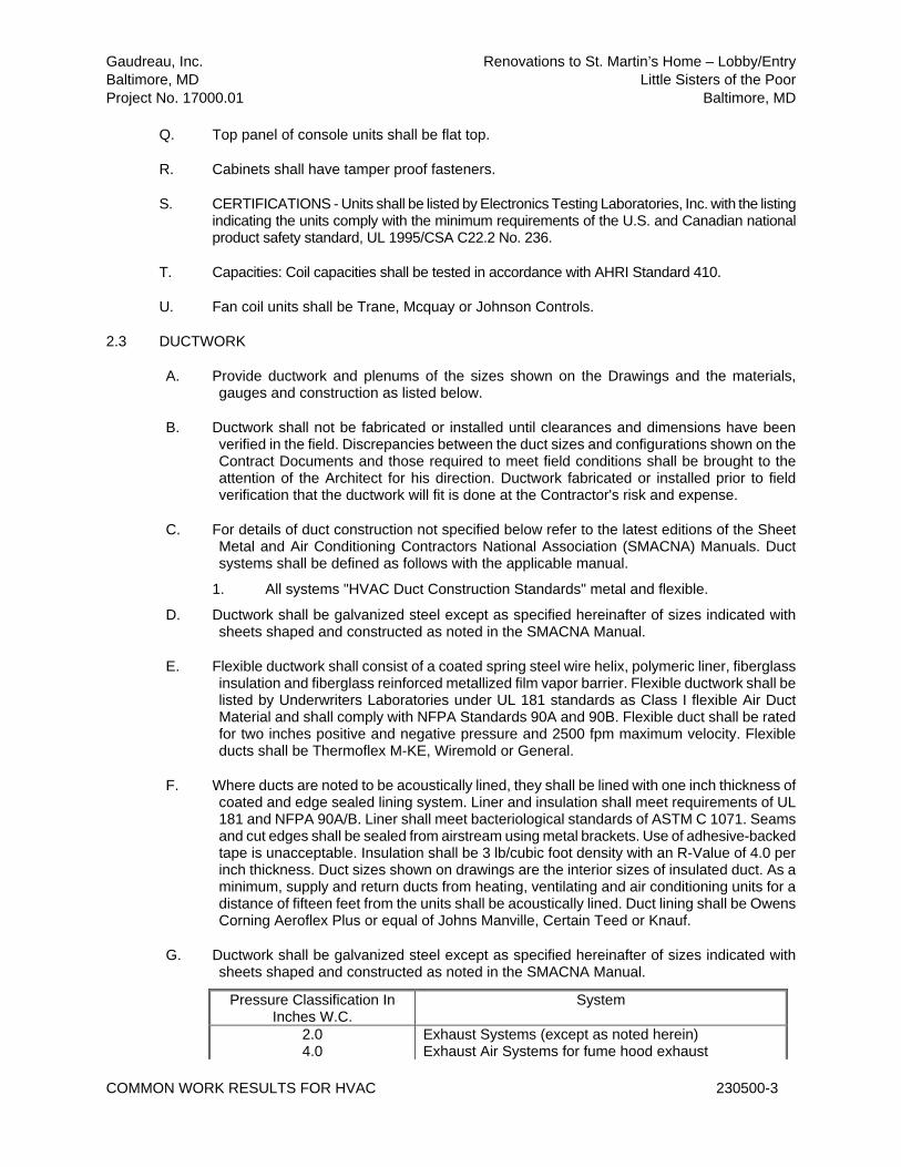
Gaudreau, Inc. Renovations to St. Martin’s Home – Lobby/Entry
Baltimore, MD Little Sisters of the Poor
Project No. 17000.01 Baltimore, MD
COMMON WORK RESULTS FOR HVAC 230500-3
Q. Top panel of console units shall be flat top.
R. Cabinets shall have tamper proof fasteners.
S. CERTIFICATIONS - Units shall be listed by Electronics Testing Laboratories, Inc. with the listing indicating the units comply with the minimum requirements of the U.S. and Canadian national product safety standard, UL 1995/CSA C22.2 No. 236.
T. Capacities: Coil capacities shall be tested in accordance with AHRI Standard 410.
U. Fan coil units shall be Trane, Mcquay or Johnson Controls.
2.3 DUCTWORK
A. Provide ductwork and plenums of the sizes shown on the Drawings and the materials, gauges and construction as listed below.
B. Ductwork shall not be fabricated or installed until clearances and dimensions have been verified in the field. Discrepancies between the duct sizes and configurations shown on the Contract Documents and those required to meet field conditions shall be brought to the attention of the Architect for his direction. Ductwork fabricated or installed prior to field verification that the ductwork will fit is done at the Contractor's risk and expense.
C. For details of duct construction not specified below refer to the latest editions of the Sheet Metal and Air Conditioning Contractors National Association (SMACNA) Manuals. Duct systems shall be defined as follows with the applicable manual.
1. All systems "HVAC Duct Construction Standards" metal and flexible.
D. Ductwork shall be galvanized steel except as specified hereinafter of sizes indicated with sheets shaped and constructed as noted in the SMACNA Manual.
E. Flexible ductwork shall consist of a coated spring steel wire helix, polymeric liner, fiberglass insulation and fiberglass reinforced metallized film vapor barrier. Flexible ductwork shall be listed by Underwriters Laboratories under UL 181 standards as Class I flexible Air Duct Material and shall comply with NFPA Standards 90A and 90B. Flexible duct shall be rated for two inches positive and negative pressure and 2500 fpm maximum velocity. Flexible ducts shall be Thermoflex M-KE, Wiremold or General.
F. Where ducts are noted to be acoustically lined, they shall be lined with one inch thickness of coated and edge sealed lining system. Liner and insulation shall meet requirements of UL 181 and NFPA 90A/B. Liner shall meet bacteriological standards of ASTM C 1071. Seams and cut edges shall be sealed from airstream using metal brackets. Use of adhesive-backed tape is unacceptable. Insulation shall be 3 lb/cubic foot density with an R-Value of 4.0 per inch thickness. Duct sizes shown on drawings are the interior sizes of insulated duct. As a minimum, supply and return ducts from heating, ventilating and air conditioning units for a distance of fifteen feet from the units shall be acoustically lined. Duct lining shall be Owens Corning Aeroflex Plus or equal of Johns Manville, Certain Teed or Knauf.
G. Ductwork shall be galvanized steel except as specified hereinafter of sizes indicated with sheets shaped and constructed as noted in the SMACNA Manual.
Pressure Classification In Inches W.C.
System
2.0 4.0
Exhaust Systems (except as noted herein) Exhaust Air Systems for fume hood exhaust

Gaudreau, Inc. Renovations to St. Martin’s Home – Lobby/Entry
Baltimore, MD Little Sisters of the Poor
Project No. 17000.01 Baltimore, MD
COMMON WORK RESULTS FOR HVAC 230500-4
2.0 Return Air System 4.0 Supply Air System
H. Duct connections to air handling units and elsewhere as required to compensate for expansion and contraction and noise reduction shall be made with UL approved glass fabric such as Ventglas as manufactured by Vent Fabrics, Inc.
I. On low pressure systems duct details shall be as follows:
1. Square elbows Figure 2-2 2. Hangers Figure 4-4 3. Tee connections Figure 2-7 4. Register on trunk Figure 2-16 5. Volume dampers Figures 2-14 and 2-15
J. Provide manual volume dampers as shown on the Drawing and additionally as required to properly balance the air distribution systems as directed by the independent Test and Balance Agency.
K. Fire dampers shall be provided where indicated and elsewhere as required to comply with requirements of NFPA 90A and Building Code Requirements. Fire dampers shall be multi-leaf accordion type, held open by adequate heavy gauge wires and suitable, calibrated fusible links. Fire dampers shall be Ruskin, Prefco, Nailor or Air Balance, Inc. Fire dampers shall be of a suitable type and rating for the wall construction in which they are to be installed. See the finish schedule on the Architectural Drawings. Fire dampers shall have UL label of acceptance or proof of acceptance to meet local requirements for the wall construction in which they are installed. Vertical dampers (horizontal air flow) shall close by gravity. Horizontal dampers (vertical air flow) shall be closed by suitable and positive spring closing devices. Provide adequately sized hinged access doors with cam locks to allow access to fire dampers for replacement of fusible link and resetting damper.
1. Dampers located in duct sections that are not adjacent to wall mounted air devices shall be type B dampers. Damper frames shall provide a pocket which shall store damper leaves in open position outside of air stream and shall allow 100% free air flow when open.
2. Verify that field conditions allow for the installation of type B dampers. Where field conditions do not allow the use of type B dampers, provide type A dampers. Dampers shall be designed and constructed to provide a minimum of 90% free area when the damper leaves are in the open position.
3. Behind air devices, provide thin line, type A fire dampers. Dampers shall be flangeless type with 1-7/8” galvanized steel frame with 20 gauge steel enclosure.
L. Smoke dampers shall be provided where indicated and elsewhere as required to comply with requirements of NFPA 90A and Building Code Requirements. Smoke dampers shall be of a type suitable for the wall construction in which they are to be installed. See the finish schedule on the Architectural Drawings. Smoke dampers shall have UL label 555S leakage rated or proof of acceptance to meet local requirements for the wall construction in which they are installed. Smoke damper shall be steel curtain damper and shall also serve as a fire damper. Damper actuator shall be an electro-thermal link which shall be actuated by a temperature of 165 degrees F or greater or any 0.2 amp or greater charge at 6 to 30 volts AC or DC. Separation shall occur in less than 10 seconds following electrical stimulation. Electrical stimulation shall be provided by smoke detectors furnished under Division 16. Wiring from the smoke detector to the damper shall be furnished under Division 16. Smoke

Gaudreau, Inc. Renovations to St. Martin’s Home – Lobby/Entry
Baltimore, MD Little Sisters of the Poor
Project No. 17000.01 Baltimore, MD
COMMON WORK RESULTS FOR HVAC 230500-5
dampers shall be designed and constructed to provide minimum 90 percent free area of duct. Provide access to smoke dampers for replacement of the electro-thermal link and resetting damper. Dampers shall be Prefco Products model LPB (5650 Fender 6" high).
M. Combination fire/smoke dampers meeting or exceeding the following specifications shall be furnished and installed at locations shown on plans. Dampers shall be the requirements of NFPA 90A, 92A and 92B and shall be classified for use for fire resistance ratings of less than 3 hours, in accordance with UL555. Dampers shall further be classified as Smoke Dampers in accordance with the latest version of UL555S. The leakage rating under UL555S shall be leakage Class 2. In addition to the leakage ratings, the dampers and their actuators shall be qualified under UL555S to an elevated temperature of 250 degrees F or 350 degrees F depending upon the actuator. Appropriate electric actuators shall be installed by the damper manufacturer at time of damper fabrication. Electric actuators shall have been energized hold open tested for a period of at least one year with no spring return failures. Damper and actuator shall be supplied as a single entity which meets all applicable UL 555 and UL555S qualifications for both dampers and actuators. Each damper shall be rated for leakage and airflow in either direction through the damper. Each combination fire/smoke damper shall be equipped with a “controlled closure” quick detect heat actuated release device to prevent duct and HVAC component damage. Instantaneous damper closure is unacceptable. Damper frame shall be minimum 16 gauge galvanized steel formed into a structural hat channel reinforced at corners. Damper blades shall be single skin galvanized steel 16 gauge minimum with three longitudinal grooves for reinforcement. Bearings shall be stainless steel sleeve turning in an extruded hole in the frame. Blade edge seals shall be inflatable silicone coated fiberglass and galvanized steel mechanically locked into blade edge (adhesive or clip on seals are not acceptable). Jamb seals shall be stainless steel compression type. Each damper shall be supplied with a factory mounted sleeve of 17 inch minimum length. Dampers shall be Ruskin model FSD36 or equal.
2.4 HEATING AND CHILLED WATER PIPING AND VALVING
A. Piping
IPS Grooved Piping System: All grooved components shall be as manufactured by Victaulic Company of America or an approved equal and shall conform to local code approval and/or as listed by ANSI-B-31.1, B-31.9, ASME, UL/FM, IAPMO or BOCA. Grooved end product manufacturer shall be ISO-9001 certified. (Press fit systems will not be accepted). Where non-groove system components are used in this piping system, the Contractor shall provide approved transition connections between dissimilar components. Pipe/Grooved (Schedule 40): Carbon steel, A-53B/A-106B/A-120. Roll or cut grooved ends as appropriate to pipe material, wall thickness, pressures, size and method of joining. Pipe ends shall be grooved in accordance with Victaulic current listed standards conforming to ANSI/AWWA C-606.
B. Fittings
1. Mechanical Couplings for Joining Carbon Steel Pipe: Mechanical couplings shall be Victaulic Style 07 (Zero-Flex) Rigid coupling or Style HP-70 Rigid coupling for high pressure service or an approved equal. Victaulic Style 77 or 75 or an approved equal coupling shall be used at pumps and other mechanical equipment to reduce noise and vibration. Couplings shall be cast of ductile iron conforming to ASTM A-536, Grade 65-45-12 or malleable iron conforming to ASTM A-47, Grade 32510.
2. Reducing Mechanical Couplings: Victaulic Style 750 reducing couplings or an approved equal for pipe runs for direct reduction on 2" through 3" pipe sizes.
3. Snap Joint Quick Disconnect Mechanical Coupling: Victaulic Style 78 or an approved equal snap joint couplings for quick disconnect requirements.

Gaudreau, Inc. Renovations to St. Martin’s Home – Lobby/Entry
Baltimore, MD Little Sisters of the Poor
Project No. 17000.01 Baltimore, MD
COMMON WORK RESULTS FOR HVAC 230500-6
4. Boltless Couplings: Victaulic Style 791 boltless couplings or an approved equal for tamper resistant requirements.
5. Mechanical Coupling Bolts: Mechanical coupling bolts shall be heat treated carbon steel track head conforming to physical properties of ASTM A-183, minimum tensile strength 110,000 PSI as provided standard by Victaulic or an approved equal. Optional: Cadmium plated to ASTM A-165.
C. Flange Adapters
1. Vic-Flange adapter Style 741 or an approved equal, 2"-3", for connection to ANSI Class 125/150 flanged components. Cast of ductile iron conforming to ASTM A-536 or malleable iron conforming to ASTM A-47.
2. Vic-Flange adapter Style 743 or an approved equal, 2"-3", for connection to ANSI Class 250/300 flanged components. Cast of ductile iron conforming to ASTM A-536.
3. Victaulic flanged adapter nipples, 3/4"-3" (20-600 mm), No. 41, 45 and 46 for connection to ANSI Class 125, 150 and 300 flanged components.
D. Miscellaneous Connections (Vent, Drain, Pressure, Temperature, Taps, Etc…):
1. Vic-Let Style 923 or an approved equal, ½" or ¾" npt outlet on 4" and larger header sizes rated for 300 PSI.
2. Vic-O-Well Style 924 or an approved equal to accommodate industrial glass bulb thermometers with standard 1¼" 18 NEF 2B extra fine thread.
3. Outlet Mechanical Coupling: Victaulic Style 72 or an approved equal outlet couplings on header sizes 1½" through 3" for grooved or threaded reduced outlet sizes ½" through 2".
E. Gaskets
1. Water and oil free air service shall be Grade "E" EPDM compound (green color coded) conforming to ASTM D-2000 designation 2CA615A25B24F17Z. Temperature operating range -30oF to +230oF.
2. Oil and air service with oil vapors shall be Grade "T" nitrile compound (orange color coded) conforming to ASTM D-2000 designation 5BG615A14B24. Temperature operating range -20oF to +180oF.
F. Valves:
1. Multipurpose Valves: Combination shut off, throttling and non-slam check valves shall be Series Vic 300 or an approved equal butterfly valve assembly with standard Vic-Check. Working pressures to 300 PSI. Memory stops standard.
2. Ball Valves: Victaulic Series 721 or an approved equal standard port ball valve 1½"-6" ductile iron, ASTM A-536, micro finish steel chrome plated or stainless steel ball and stem, TFE seats, 600 PSI. Note: Provide Victaulic Style 722 or an approved equal threaded end ball valve, forged brass body, ASTM B-16, where required for ¼" through 2" threaded pipe end conditions, 600 PSI.
3. Victaulic Series 723 diverter ball valve or an approved equal, 2" with 3 ports, 600 PSI, common bottom inlet for diverting flow 90o left or right. Ductile iron body, ASTM A-536, with Type 316 stainless steel ball and stem. For 180o operation, contact Victaulic for special order.
4. In lieu of Victaulic ball valves, the following valves are acceptable: 4" and smaller: Bronze threaded or soldered end, 600 lb. w.o.g. non-shock, Watts No. 6000 or 6001.
5. Check Valves (Swing) Victaulic Series 712 check valve or an approved equal, 2"-4". Horizontal installation. Working pressure to 300 PSI. Ductile body, ASTM A-536 and stainless clapper. EPDM, nitrile or optional viton bumper and bonnet seals. Stainless wetted parts.
6. In lieu of Victaulic valve, 2-1/2" and larger: G391, IBBM, 125 lb. std. flanged swing check, bolted cap with metal disc; 2" and smaller: B-345, 200 lb. bronze, swing check,

Gaudreau, Inc. Renovations to St. Martin’s Home – Lobby/Entry
Baltimore, MD Little Sisters of the Poor
Project No. 17000.01 Baltimore, MD
COMMON WORK RESULTS FOR HVAC 230500-7
screw cap and threaded ends. 7. Valve Automation Victaulic quarter turn valves or an approved equal shall be designed
to accept remote actuation operators and shall be suitable for electric or pneumatic actuation in 2 and 3 way design. Accessories shall include solenoids, positioners and position indicating switches. Actuators shall be submitted for approval with these valves.
8. Three Way Automated Butterfly Valve: For mixing usage, provide Victaulic grooved end 3 way automated butterfly valves or an approved equal. Configure valve assembly in accordance with design conditions.
9. Bolted Branch Outlet: Branch reductions on 2" through 3" header piping shall be made with Victaulic hole cut products or an approved equal. Style 920 or Style 921 Mechanical-T Outlet with locating collar engaging into hole or Style 72 outlet coupling for use in joining grooved pipe with a branch connection at the joint.
10. Expansion Joints: Expansion and contraction compensation shall be achieved utilizing Victaulic Style 150 Mover or an approved equal, 2"-3". Expansion joints shall be sized and supported in accordance with design conditions and manufacturer performance.
11. Victaulic or an approved equal fittings shall be full flow ductile or cast iron fittings, steel fittings or segmentally welded fittings with grooves or shoulders designed to accept Victaulic or an approved equal grooved end couplings. Refer to manufacturer's data for style numbers.
12. Standard fittings shall be cast of ductile iron conforming to ASTM A-536, Grade 65-45-12 or malleable iron conforming to ASTM A-47, Grade 32510.
13. Standard steel fittings shall be forged steel conforming to ASTM A-234, Grade WPB 0.375" wall.
14. Standard segmentally welded fittings, i.e., tees, elbows, laterals, etc. shall be fabricated of standard weight C.S. pipe conforming to ASTM A-53, Type F, E or S, Grade B. All 90o and 45o elbows will be full flow, not mitre welded. Note: Victaulic Style 47 Dielectric Waterway or an approved equal when connecting dissimilar metals in liquid systems. 1/2" through 3" size range available with grooved, threaded or plain end combinations.
15. Coatings: Standard fittings and couplings shall be provided with an alkyd enamel finish. Galvanized fittings and couplings shall conform to ASTM A-153. Zinc electroplated fittings and couplings shall conform to ASTM B633.
16. T-Type Strainer: Victaulic Series 730 or an approved equal, 300 PSI T-Type strainer shall consist of ductile iron or steel body, Type 304 stainless steel convoluted removable basket with No. 12 mesh, 2"-3" strainer sizes, 57% free open area, for pressures up to 300 PSI.
17. Y-Type Strainer: Victaulic Series 732 or an approved equal, 300 PSI Y-Type strainer shall consist of ductile iron body, ASTM A-536, Type 304 stainless steel cylindrical removable baskets with 1/16" diameter perforations and 41% open area 2"-3" strainer sizes or 1/8" strainer sizes diameter perforations and 40% open area 4"-12" strainer sizes for pressures up to 300 PSI.
18. Suction Diffuser – Grooved/Flanged End: Series 731, rated to 300 PSI, ductile or steel body, basket strainer 304 stainless sheet with 3/16" diameter holes, 51% open area. Removable start up pre-filter 16 mesh bronze screen. Outlets for pressure/temperature drain connections. Access coupling Style 07. Flange Series 741 ANSI Class 125 or 150 standard.
19. Flow Measuring Sensors – Grooved End: Venturi Type: Victaulic Style 733 or an approved equal rated 250 PSI. Sizes 2½"-3" diameter. Minimum straight pipe installation of 5 diameters upstream and 2 diameters downstream.
20. Orifice Indicator: Victaulic Style 734 or an approved equal orifice plate rated for 250 PSI. Minimum straight pipe installation, 2½"-4" diameter same as venturi type. Minimum straight pipe installation 10 diameters upstream and 4 diameters downstream. Note: Flow sensors available in threaded or sweat ends. Sizes ½"-2" diameter.

Gaudreau, Inc. Renovations to St. Martin’s Home – Lobby/Entry
Baltimore, MD Little Sisters of the Poor
Project No. 17000.01 Baltimore, MD
COMMON WORK RESULTS FOR HVAC 230500-8
21. Test Meter: Provide Style S4 or L6 portable master meter for flow measurement. 22. Globe Valves 2-1/2" and larger: G512, IBBM, 125 lb. std. flanged, bolted bonnet,
OS&Y, with renewable seat and disc; 2" and smaller: B29, 150 lb. bronze, union bonnet, threaded ends, with renewable seat and disc.
2.5 FANS – CEILING
A. Provide ceiling fans in accordance with the schedule on the drawings and the specification below.
B. Ceiling fans shall be complete with insulated housing, white finish ceiling grille, backdraft damper and direct drive centrifugal fan. Disconnect means for motor shall be provided inside housing by cord and plug. Motor to be provided with inherent overload protection.
C. Ceiling fans shall be Greenheck or approved equal.
2.6 BASEBOARD HEATERS
A. Furnish and install hot water baseboard with enclosure and active fin length of size and BTU/HR per linear foot as indicated on the drawings.
B. Elements shall be steel or copper/aluminum and be available in lengths from 1' to 12' with 6" increments.
C. Fins shall be galvanized with .032" thickness or aluminum with .020" thickness.
D. Unit shall have a full 18 gauge mounting back plate primed, phosphatized C.R.S. and a urethane gasket for air seal.
E. Fin tube/pipe hanging cradles shall be 14 gauge phosphatized C.R.S. with prime finish. Cradles shall be expansion type and shall accommodate 1-3/4" linear expansion for quiet operation.
F. All joints shall be made with internal joggle joiners to provide hairline joints without external fasteners.
G. All joints, end caps, corner trims, access covers, etc. shall be provided for a full/complete baseboard system.
H. Baseboard shall be Rittling Model BGVL or approved equal by American Stabilis or Vulcan.
PART 3 - EXECUTION
3.1 COMMISSIONING
A. Provide complete commissioning for all equipment and systems furnished under the mechanical and plumbing scopes of work. Commissioning shall include providing a commissioning plan along with contract document review, providing pre-functional and functional tests with follow up reports for all systems under the mechanical and plumbing divisions of work, and provide post commissioning and validation assistance services as outlined in the following paragraphs.

Gaudreau, Inc. Renovations to St. Martin’s Home – Lobby/Entry
Baltimore, MD Little Sisters of the Poor
Project No. 17000.01 Baltimore, MD
COMMON WORK RESULTS FOR HVAC 230500-9
B. Review the design documents (drawings and specifications) as they are prepared to ensure inclusion of material covering the contractor’s responsibilities for commissioning; provide comments and suggestions for designer consideration.
C. Prepare the design-phase commissioning plan.
1. During the construction phase the commissioning agency shall carry out the following scope of work: a. Organize and lead the commissioning team. b. Review shop drawings and equipment submittals for information affecting
the commissioning process. c. Update the commissioning plan to reflect equipment and controls data from
the submittals, and provide commissioning schedule information that the contractor can integrate into the project schedule.
d. Schedule and lead commissioning meetings. e. Establish and maintain a system for tracking issues needing resolution. f. Review the project schedule periodically to ensure commissioning activities
are properly incorporated; provide feedback to the designer as needed. g. Perform on-site observations during construction. h. Monitor correct component and equipment installation; including controls
point to point checkouts. Document all observations. i. Witness equipment and system start-ups as deemed necessary. Ensure
complete documentation of same.
D. During the acceptance phase the commissioning agency shall carry out the following scope of work:
1. Review and inspect, on a sample basis, the testing, adjusting and balancing work that has been carried out by another agency.
2. Conduct functional performance testing of sub-systems, systems, and interactions between systems, leading to acceptance of the completed work.
3. Document results of all tests witnessed. 4. Organize and direct the training of O & M personnel.
E. During the post-acceptance (validation) phase the commissioning agency shall carry out the following scope of work:
1. Conduct functional performance testing of sub-systems, systems, and interactions between systems that could not be carried out prior to acceptance due to unsuitable weather conditions.
2. Prepare and submit a final commissioning report. 3. Provide follow-up for quality performance during the guarantee period.
F. The commissioning scope of work shall be provided for the following building systems:
1. HVAC control system. 2. BMS System. 3. Air Handling Units 4. VAV boxes 5. Baseboard Heaters 6. Pumps 7. Fans
3.2 INSULATION
A. After the systems have been installed and tested, insulation as specified below shall be applied. Materials shall be Underwriters Laboratory, Inc., approved and shall be applied as recommended by the manufacturer's written instructions. Materials used shall be the products of Owens Corning, Manville, Knauff Corporation, Armstrong, Certainteed, Miracle

Gaudreau, Inc. Renovations to St. Martin’s Home – Lobby/Entry
Baltimore, MD Little Sisters of the Poor
Project No. 17000.01 Baltimore, MD
COMMON WORK RESULTS FOR HVAC 230500-10
Adhesive, Moneco or Benjamin Foster and shall be similar to those products that meet the specifications below.
B. Ductwork
1. Exposed supply ductwork and return air ductwork except where ductwork located in the room supplied shall be insulated with 1-1/2 inch thickness of 6 PCF fiberglass board with reinforced foil faced ASJ vapor barrier jacket secured to duct with Graham weld pins or perforated base stick clips set in Moneco M46420 adhesive. Pins shall be covered with finish cap to match insulation. Butt joints and seams and cover with vapor barrier mastic.
2. Concealed supply air duct, return air duct and outside air duct shall be covered with 1-1/2 inch thickness of 3/4 pcf flexible fiberglass duct covering with reinforced foil and kraft paper vapor barrier FRK jacket. Insulation shall be applied to duct over a 100 percent coverage of duct adhesive such as Benjamin Foster 85-20. Edges shall be butted together with a vapor barrier lap of 2 inch minimum. Seal joint and punctures with Benjamin Foster 30-35. Where ducts are over 24 inches in width, weld pins and caps shall be used to secure insulation to underside of duct. Secure laps with adhesive and flared staples on 4 inch center.
3. Ductwork that is internally lined is not required to be insulated externally as indicated herein. When exterior insulation is deleted, liner should be 1 inch thick.
4. Ductwork exposed to outdoor elements shall be covered with 1-1/2 inch thickness of 6 PCF rigid fiber board with vapor barrier jacket, applied to duct with stick pins and adhesive. Joints shall be lapped and sealed. Finish with 2 coats of lagging weatherproof adhesive imbedded with glass cloth using corner beads on edges. Paint with weatherproof paint suitable for the installation. All four sides of duct shall additionally be covered with 22 gauge galvanized sheet metal cover which shall be sloped for positive drainage.
C. Piping
1. Hot water heating piping shall be covered with 1 ½ inch thickness for piping up to 1-1/2 inches and 2 inch thickness for piping over 2” in size of long strand glass fiber insulation with all service vapor barrier jacket with self-sealing pressure sensitive lap, Manville AP-T, for piping up to 3 inches in size. Fittings shall be covered with 2000 (lower flame spread) precut PVC fitting covers with fiberglass insulation insert. Cover shall be sealed to adjacent insulation with vapor retarder mastic and then covered with pressure sensitive tape.
2. Chilled water heating piping Insulation shall be as follows:
a. One (1) piece molded heavy density fibrous glass with a thermal conductivity ("K") of 0.23 at 75°F mean temperature, for services from 35°F to 70°F Insulation shall have a super-absorbent wicking cloth lining the core and extending to the insulation surface.
b. Molded fibrous glass pipe insulation shall comply with the requirements of ASTM C 547 and meet ASTM C 585 for sizes required in the particular system. It shall be of a wicking type suitable for installation on piping systems as defined in section 1.01 SCOPE above. Product shall include a factory applied integral vapor retarder extending under the evaporator area of the wick and covering not less than 98% of the circumference of the product. Exposed evaporator area shall be not less than 0.1 sq. ft./linear ft. of product.
c. Fittings and valves shall be insulated per manufacturer’s instructions: i. Fittings and valves shall be wrapped continuously with wicking
material prior to installing insulation to ensure a continuous path for removal of condensation.
ii. Standard site fabricated connections (e.g. mitered, segmented, or

Gaudreau, Inc. Renovations to St. Martin’s Home – Lobby/Entry
Baltimore, MD Little Sisters of the Poor
Project No. 17000.01 Baltimore, MD
COMMON WORK RESULTS FOR HVAC 230500-11
fish mouth) are recommended for bends and fittings. iii. Standard PVC fittings with blanket insulation or molded/preformed
fiberglass fittings may be used. iv. Standard over-sizing practices shall be used for valves and flanges.
d. All piping shall be supported in such a manner that the insulation is not
compromised by the hanger or the effects of the hanger. In all cases, hanger spacing shall be such that the circumferential joint may be made outside the hanger. Cover the evaporating holes with contractor supplied manufacturer approved Sealing Tape for the length of the metal saddle. i. Piping systems 3" (75 mm) in diameter or less, insulated with
fiberglass pipe insulation, may be supported by placing saddles of the proper length and spacing under the insulation as designated in Owens Corning Pub. 1-IN-14210.
ii. For hot or cold piping systems larger than 3" (75 mm) in diameter, operating at temperatures less than +200F (93C) and insulated with fiberglass, inserts such as foam or high-density fiberglass with sufficient compressive strength shall be used to support the weight of the piping system.
iii. On vertical runs, insulation support rings shall be used as indicated on contract drawings.
e. Accessory materials installed as part of insulation work under this section shall include (but not be limited to): i. Manufacturer approved wick material for wrapping valves and
fittings ii. Closure Materials – Manufacturer approved Sealing Tape, and
mastics. iii. Support Materials - Hanger straps, hanger rods, saddles, support
high-density blocks, and support rings.
f. All accessory materials shall be installed in accordance with project drawings and specifications, manufacturer's instructions, and/or in conformance with the current edition of the Midwest Insulation Contractors Association (MICA) "Commercial & Industrial Insulation Standards."
g. Piping insulation shall be manufactured by Owens Corning (VaporWick®) or approved equal.
3. On exposed insulated piping in finished areas within seven feet of the floor, provide 0.016 aluminum insulation jackets. This does not include piping exposed in unfinished areas such as boiler rooms, storage rooms, etc.
3.3 AUTOMATIC TEMPERATURE CONTROLS
A. General
1. For General Mechanical Requirements, see Section 230000. 2. Connect new equipment to the existing DDC BAS. 3. Comply with all code requirements and fire safety requirements as specified in
Section 230000. 4. Provide graphics for the new equipment. 5. The control system Installer shall provide a list of no less than 5 similar projects which
have building control systems as specified. These projects must be on-line and functional such that the Owner's representative would observe a system in full operation. The control system Installer must be a direct, wholly owned branch of a national controls manufacturer, not a representative or a distributor.
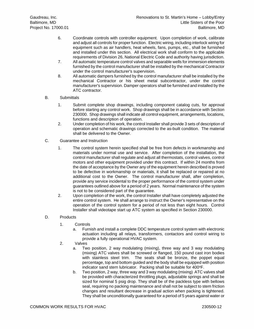
Gaudreau, Inc. Renovations to St. Martin’s Home – Lobby/Entry
Baltimore, MD Little Sisters of the Poor
Project No. 17000.01 Baltimore, MD
COMMON WORK RESULTS FOR HVAC 230500-12
6. Coordinate controls with controller equipment. Upon completion of work, calibrate and adjust all controls for proper function. Electric wiring, including interlock wiring for equipment such as air handlers, heat wheels, fans, pumps, etc., shall be furnished and installed under this section. All electrical work shall conform to the applicable requirements of Division 26, National Electric Code and authority having jurisdiction.
7. All automatic temperature control valves and separable wells for immersion elements furnished by the control manufacturer shall be installed by the mechanical Contractor under the control manufacturer's supervision.
8. All automatic dampers furnished by the control manufacturer shall be installed by the mechanical Contractor or his sheet metal subcontractor, under the control manufacturer's supervision. Damper operators shall be furnished and installed by the ATC contractor.
B. Submittals
1. Submit complete shop drawings, including component catalog cuts, for approval before starting any control work. Shop drawings shall be in accordance with Section 230000. Shop drawings shall indicate all control equipment, arrangements, locations, functions and description of operation.
2. Under completion of his work, the control Installer shall provide 3 sets of description of operation and schematic drawings corrected to the as-built condition. The material shall be delivered to the Owner.
C. Guarantee and Instruction
1. The control system herein specified shall be free from defects in workmanship and materials under normal use and service. After completion of the installation, the control manufacturer shall regulate and adjust all thermostats, control valves, control motors and other equipment provided under this contract. If within 24 months from the date of acceptance by the Owner any of the equipment herein described is proved to be defective in workmanship or materials, it shall be replaced or repaired at no additional cost to the Owner. The control manufacturer shall, after completion, provide any service incidental to the proper performance of the control system under guarantees outlined above for a period of 2 years. Normal maintenance of the system is not to be considered part of the guarantee.
2. Upon completion of the work, the control Installer shall have completely adjusted the entire control system. He shall arrange to instruct the Owner's representative on the operation of the control system for a period of not less than eight hours. Control Installer shall videotape start up ATC system as specified in Section 230000.
D. Products
1. Controls a. Furnish and install a complete DDC temperature control system with electronic
actuation including all relays, transformers, contactors and control wiring to provide a fully operational HVAC system.
2. Valves a. Two position, 2 way modulating (mixing), three way and 3 way modulating
(mixing) ATC valves shall be screwed or flanged, 150 pound cast iron bodies with stainless steel trim. The seats shall be bronze, the poppet equal percentage, top and bottom guided and the body shall be equipped with position indicator sand stem lubricator. Packing shall be suitable for 400oF.
b. Two position, 2 way, three way and 3 way modulating (mixing) ATC valves shall be provided with characterized throttling plugs, adjustable springs and shall be sized for nominal 5 psig drop. They shall be of the packless type with bellows seal, requiring no packing maintenance and shall not be subject to stem friction changes and resultant decrease in gradual action when packing is tightened. They shall be unconditionally guaranteed for a period of 5 years against water or

Gaudreau, Inc. Renovations to St. Martin’s Home – Lobby/Entry
Baltimore, MD Little Sisters of the Poor
Project No. 17000.01 Baltimore, MD
COMMON WORK RESULTS FOR HVAC 230500-13
air leakage. Packed type valves may be substituted for packless type valves provided the guarantee specified for packless types is furnished for the packed type.
c. Heating water coils and baseboard heaters shall be two way; CAV, VAV, hot water re-heat and unit heater valves shall be two way.
3. Thermostats, Room a. Room thermostats shall be low voltage proportional thermostats, range 50oF to
90oF with dual cooling and heating setpoints. The thermostats shall be capable of networking back to the master DDC controller.
b. Thermostats shall also be provided with integral momentary push button that will override control of heat pump to the occupied mode for up to a 4 hour (adjustable) time period.
c. The thermostat shall have an adjustable potentiometer to adjust temperature 3oF from the programmed heating and cooling setpoints.
4. Sensors a. Insertion and immersion sensors shall be nickel wound resistive type, epoxy
coated Siemens RTD type. They shall comply with the requirements set by the controllers. A separate socket complete with transfer medium shall be furnished or each immersion sensor. Where installed in insulated ducts the sockets and mounting brackets shall be arranged to permit full insulation on the duct and piping. Outdoor air sensors shall be provided with shield weather cover.
5. Thermostats, Insertion a. Insertion and immersion thermostats shall be of liquid filled type with fully
compensated capillary tubing similar to A-19. They shall be equipped with adjustable sensitivity. They shall also comply with the requirements set down for the room thermostats and controller. A separable socket shall be furnished for each immersion thermostat. Where installed in insulated ducts, the sockets and mounting brackets shall be arranged to permit full insulation on the duct and piping.
6. Relays a. Electric relays and gradual acting switches shall be furnished and installed as
required for the successful operation of the system. All switches shall include suitable indicating name plates.
7. Dampers a. Dampers shall be constructed of galvanized steel frames and blades. Spacing
of blade axis shall not exceed 6". Maximum blade length 48" without intermediate bearing and frame stiffener. Provide friction free nylon trunnion bearings and steel linkages and pivot pins with suitable locking retainers. Dampers shall be provided with synthetic elastomer seals on blade edges and frame sides. Damper construction shall be as Ruskin CD 45.
8. Operators a. Damper operators shall be of the solid state motor driven type acting against a
spring loaded shaft. Fail safe operation shall be proved by the spring, which returns the actuator in the event of power failure. Damper operators shall be of such a size to have 50% more power than required to operate the damper. Actuators shall operate on a 0 to -2 VDC input.
9. Unit Controllers a. Provide DDC controllers for each air handling unit and other mechanical
equipment to provide the specified sequence of control. 10. Space Humidistat
a. The relative humidity sensor shall be a bulk polymer element type with minimum accuracy of +/- 2% RH at 77oF, including hysterisis, linearity and repeatability. The sensor shall have an operating range of 0 to 100% RH and operating temperature of 20oF to 130oF. Signal output shall be 4-20 MA linear

Gaudreau, Inc. Renovations to St. Martin’s Home – Lobby/Entry
Baltimore, MD Little Sisters of the Poor
Project No. 17000.01 Baltimore, MD
COMMON WORK RESULTS FOR HVAC 230500-14
proportioning. 11. Carbon Dioxide Sensors
a. Provide an indoor air quality control system to maintain a maximum CO2 level in ambient air as specified herein. Provide duct or space type carbon dioxide as indicated on the plans.
b. The carbon dioxide transducer(s) shall have a non-dispersive infrared optical sensor cell for long life, and accurate CO2 sensing. The CO2 transducer shall have a linear analog output signal calibrated over a range of 0 to 2000 ppm.
c. The CO2 transducer(s) signal(s) shall be used as inputs to the ventilation control system, which shall be adjustable, to operate outdoor air ventilation dampers such that the indoor air CO2 level does not exceed 1000 ppm.
E. EXECUTION AND SEQUENCE OF OPERATION
1. Alarms: a. Provide alarms notifications as described above and as indicated on the
drawings. 2. Duct Smoke Detectors
a. Local duct smoke detectors provided under Division 16. From one contact of each detector, air handling apparatus smoke detectors shall de-energize the particular air handling device served by the smoke detector. Unit outdoor air dampers shall additionally be closed. Provide all electrical wiring between duct smoke detectors and air handling apparatus, including motor operators to make a complete and operable system. Installer shall be responsible for all coordination between smoke detector supplier and automatic temperature controls.
3. Coordination with Fire Alarm System a. ATC Installer shall be responsible for making operation of ATC system
completely compatible with Fire Alarm System, Room Smoke Detector, etc., as indicated under Division 16. ATC system shall operate as indicated in Division 16 when building is in fire or smoke alarm condition.
3.4 TESTING AND BALANCING AIR & WATER SYSTEMS
A. The air distribution system and water systems shall be balanced and adjusted by an independent organization specializing in this type of work to distribute the quantities noted on the drawings. The balancing agency shall be a member of the Associated Air Balance Council or the National Environmental Balancing Bureau.
B. Test equipment must be approved by the Architect and properly calibrated prior to starting work. Repairs, alterations, adjustments and readjustments necessary to meet the design conditions shall be made.
C. The balancing agency shall review the drawings before installation and advise the Contractor of additional dampers required in the ductwork, flow devices and balancing valves in the water piping, etc., to effectively and properly balance the systems. These devices shall be installed at no additional cost to the Owner.
D. At the completion of the balancing and adjusting and prior to the operating test, submit to the Architect three (3) certified typewritten reports to be retained by the Architect. Reports shall include:
1. Velocities and air quantities at supply returns and exhaust outlets installed under this contract.
2. Pressure and/or temperature difference across various pieces of equipment.

Gaudreau, Inc. Renovations to St. Martin’s Home – Lobby/Entry
Baltimore, MD Little Sisters of the Poor
Project No. 17000.01 Baltimore, MD
COMMON WORK RESULTS FOR HVAC 230500-15
3. Air temperature delivered from heating and cooling equipment. 4. Water quantities at flow indicators. 5. Schedule of equipment. 6. Speed of belt driven equipment. 7. Nameplate data on motors installed under this contract. 8. Actual operating voltage and ampacity readings on motors. 9. Separate six hour operating tests shall be made during the cooling season and during
the heating season in which an hourly record shall be made of the following: a. Settings of control equipment. b. Outside weather conditions. c. Thermostat readings. d. Dry and wet bulb temperatures in spaces.
Outside temperatures shall be below 40 degrees Fahrenheit during the heating test and above 85 degrees Fahrenheit during the cooling test.
10. The outside air quantity for the variable volume air handling units shall be balanced in the following manner: a. With the air handling unit operating at maximum air quantity the outside air
damper shall be adjusted to the minimum outside air percentage as noted on the drawings. The return air damper shall be adjusted to allow the corresponding return air quantity.
b. With the air handling unit operating at maximum turn down, the outside air damper shall be adjusted to allow the same quantity of outside air (in cubic feet per minute) as allowed in Step 1 above. The return air damper shall be adjusted to allow the corresponding return air quantity.
c. The outside and return air dampers shall modulate between the two points described above.
END OF SECTION 230500

Gaudreau, Inc. Renovations to St. Martin’s Home – Lobby/Entry
Baltimore, MD Little Sisters of the Poor
Project No. 17000.01 Baltimore, MD
GENERAL ELECTRICAL REQUIREMENTS 260000 - 1
SECTION 260000
GENERAL ELECTRICAL REQUIREMENTS
PART 1 - GENERAL
1.1 REFERENCE:
A. The General Conditions, any supplementary General Conditions, General Requirements, are hereby made a part of this section as fully as if repeated herein.
1.2 REQUIREMENTS:
A. The work covered by this Section of the specification includes furnishing of all plant, labor, equipment, supplies and materials and performing all operations including excavation and backfilling, cutting, channeling and chasing necessary for the installation of wiring systems, as shown on the drawings, as hereinafter specified, and as directed by the Architect.
B. The Contractor shall perform all work hereunder in strict accordance with the rules and regulations of all applicable municipal, state, local codes, and in accordance with applicable provisions of the 2014 edition of the National Electrical Code.
C. All work shall conform to the requirements of the latest edition of the following codes, regulations and specifications:
American National Standards Institute (ANSI)
National Electrical Code 2014 (NEC)
National Fire Protection Association (NFPA)
National Electrical Manufacturers Association (NEMA)
Institute of Electrical & Electronic Engineers (IEEE)
Underwriters' Laboratories, Inc. (U.L.)
Reflector and Lamp Manufacturers' Institute (RLM)
D. The Contractor shall make application for all necessary permits, licenses and inspections as required under the above codes and shall pay all fees and charges appurtenant thereto.
E. The general arrangement of conduit, wiring and equipment shall be as shown on the contract drawings. The Contractor shall carefully examine all contract drawings and shall be responsible for the proper fitting of materials and equipment in each location as indicated, without substantial alteration. In as much as the drawings are generally diagrammatic and due to the small scale of the drawings, it is not possible to indicate all offsets, fittings and accessories, as may be required. The Contractor shall carefully investigate the site, structural, and finish conditions affecting his work and shall arrange such work accordingly, furnishing such fitting and accessories as may be required to meet such conditions, at no additional cost to the tenant. The right to make any reasonable change in location of apparatus, equipment, outlets or routing of conduit and wiring, up to the time of roughing-in is reserved by the Architect without involving any additional expense to the tenant.

Gaudreau, Inc. Renovations to St. Martin’s Home – Lobby/Entry
Baltimore, MD Little Sisters of the Poor
Project No. 17000.01 Baltimore, MD
GENERAL ELECTRICAL REQUIREMENTS 260000 - 2
1.3 SCOPE:
A. The Contractor shall furnish all labor, materials, tools, equipment and services necessary for and reasonably incidental to the complete installation of the electrical work and related systems as shown on the drawings, specified, or as necessarily required to deliver to the tenant a finished installation in good working condition, ready for continuous and satisfactory operation. The work shall include, but not limited to, the furnishing and installing of the following:
1. Panelboards
2. Fuses and Circuit Breakers
3. Starters
4. Disconnects
5. Conduit and Raceways
6. Outlet Boxes, Pull Boxes, Wire Troughs, etc.
7. Wire and Cable
8. Wiring Devices
9. Equipment Connections
10. Communications conduits
11. Grounding Systems
12. Sleeves, Hangers, Supports
13. Lighting Fixtures and Lamps
14. Tests
15. Emergency Lighting
16. Fire Alarm System
17. Occupancy Sensor Controls
18. Multi-outlet Assemblies (Plugmold)
B. All items of labor, material or equipment not shown in detail by the specifications or drawings, but incidental to, or necessary for the complete installation and proper operation of the several branches of the electrical construction described herein or reasonably implied in connection therewith, shall be furnished as if called for in detail by the specifications or drawings.
C. The Contractor shall provide all necessary temporary wiring, lighting and construction power as required to complete the work.
D. Provide coordination with the owner’s commissioning agent for the lighting system commissioning. Commissioning by the owner’s commissioning agent shall include.

Gaudreau, Inc. Renovations to St. Martin’s Home – Lobby/Entry
Baltimore, MD Little Sisters of the Poor
Project No. 17000.01 Baltimore, MD
GENERAL ELECTRICAL REQUIREMENTS 260000 - 3
Interior, Exterior, Exit, and Emergency Lighting and associated controls.
E. Provide LEED documentation for items on the LEED score card with electrical impacts.
1.4 WORKMANSHIP:
A. All materials and equipment shall be installed and completed in a first class workmanlike manner and in accordance with the best modern methods and practices. Any materials installed which do not present an orderly and reasonably neat or workmanlike appearance shall be removed and replaced when so directed by the Architect, at the Contractor's expense.
1.5 MATERIALS:
A. All materials shall be new and the best of their respective kinds, suitable for the conditions and duties imposed on them after installation. All such material shall be as found in the approved list of the National Board of Fire Underwriters. All equipment and systems shall be UL approved, listed and labeled.
B. Where material or equipment is identified by proprietary name, model number and/or manufacturer, furnish the named item or equal thereof, subject to acceptance by the Architect. Substituted items shall be equal or better in quality and performance and must be suitable for the available space, required arrangement and application. Submit any and all data necessary to determine the suitability of substituted items. The suitability of only the named item has been verified. Where more than one item is named, only the first item has been verified as suitable.
1.6 CLARIFICATION OF DRAWINGS:
A. Should a bidder find discrepancies in or omissions from the drawings or specifications, or should he be in doubt in regard to their intent, he shall notify the Architect before submitting his bid proposal. The Architect shall then send written instructions to all bidders. Oral instructions shall not be binding to either the Architect or tenant. If this Contractor fails to comply with this requirement, he shall accept the Architect's interpretation regarding the intent of the Contract documents.
1.7 LIST OF MATERIALS:
A. Immediately after award of Contract, the Contractor shall submit a complete listing of material and equipment to the Architect for preliminary review. The list shall indicate all proposed materials and equipment showing manufacturer, type, class, model, series, etc., for identification.
B. Submission and/or approval of the "List of Materials" shall not relieve the Contractor of submitting detailed shop drawings of all materials and equipment for approval and shall not constitute prior acceptance of any item before final shop drawings are submitted.
1.8 SHOP DRAWINGS:
A. The Contractor shall prepare and submit detailed dimensioned shop drawings, together with wiring diagrams, specifications, operating data, etc., for all specifically fabricated or designed equipment modified from standard items. Shop drawings shall include, but are not limited to, the following equipment or systems:

Gaudreau, Inc. Renovations to St. Martin’s Home – Lobby/Entry
Baltimore, MD Little Sisters of the Poor
Project No. 17000.01 Baltimore, MD
GENERAL ELECTRICAL REQUIREMENTS 260000 - 4
Panelboards, Transformers, Fire Alarm System, Occupancy Sensor Controls.
B. In general, catalog cuts, specification sheets, descriptive data, etc., shall be acceptable for submittal of all equipment specified by standard catalog numbers, unless directed otherwise by the Architect.
1.9 LOW VOLTAGE TESTING:
A. The Contractor shall furnish all labor, materials and instruments required to perform all necessary tests. All tests shall be performed to the satisfaction of the Architect. All defective materials and/or workmanship discovered as a result of these tests shall be removed and replaced at the Contractor's expense and the test repeated.
B. As the work progresses, tests shall be conducted to demonstrate that the system is entirely free from ground faults, short circuits, and open circuits; that the resistance to ground all non-grounded circuits, before and after connection of equipment meets the requirements of the National Electrical Code.
1.10 IDENTIFICATION:
A. Mark and permanently identify all motor starters, switches, disconnects, controls, panelboards, terminal boards, control centers and other equipment in accordance with the project nomenclature. Disconnects and starters shall include the panel and circuit number(s) in the identification plates. Identification plates shall be laminated plastic, black and white engraved letters. Lettering for panelboards, control centers, control panels, metering and instrument panels shall be in accordance with the project requirements. Attach identification plates by permanent means.
B. Label each receptacle device plate and systems furniture outlet box with the panel and circuit number(s). Label shall be made from a Kroy, Dymo or Brother hand held electronic label maker using 3/8” clear tape with 3/16” high black lettering (minimum). Where weatherproof covers are installed the panel and circuit number(s) shall be marked on the inside of the device cover using a permanent black marking pen.
C. No embossed plastic tape markers will be permitted for use in marking equipment.
D. Identification by means of marking pens or other temporary methods will not be acceptable except where specifically noted.
E. Provide color receptacles to indicate system: Normal = white/ivory; Emergency = green; Special = orange.
1.11 GUARANTEE:
A. The material and workmanship of all parts of the electrical installation specified herein shall be guaranteed unconditionally for a period of one (1) year from date of acceptance against mechanical and electrical defects arising from faulty materials or workmanship. Either replacement or repairs shall be made promptly on any defective materials or workmanship without charge during that period.
1.12 RECORD DRAWINGS:
A. Upon completion of the electrical installation, the Contractor shall deliver to the Owner one (1) set of prints of electrical contract drawings which shall be legibly marked in red pencil to

Gaudreau, Inc. Renovations to St. Martin’s Home – Lobby/Entry
Baltimore, MD Little Sisters of the Poor
Project No. 17000.01 Baltimore, MD
GENERAL ELECTRICAL REQUIREMENTS 260000 - 5
show all additions, changes and departures of the installation as compared with the original design. They shall be suitable for use in preparation of Record Drawings.
1.13 RECORD AND INFORMATION MANUAL:
A. The Contractor shall have prepared three (3) copies of the Record and Information Manual and deliver three copies of the booklet to the tenant.
B. The Manual shall be bound in a three-ring loose-leaf binder similar to "National" No. 3881, with the following title lettered on the front "Record and Information Manual (insert name of project)". No sheets larger than 8-1/2" x 11" shall be used, except sheets that may be neatly folded to 8-1/2" x 11" and used as a pullout.
C. Provide the following data in the booklet:
1. Cuts and shop drawings of all equipment with technical specifications.
2. Operation and Maintenance Procedures.
3. Servicing Instructions.
4. Copies of Warranties.
5. List of lamps showing quantity, type, wattage, manufacturer, catalog number, etc., for each fixture type (for tenant reordering).
6. Copies of Test Reports.
7. List of all vendors for the various special systems and their phone numbers.
1.14 PROTECTION OF WORK:
A. Conduit, tubing and equipment shall be cleaned before installation and shall be kept clean while the work is in progress. Open ends of the pipe, conduit and tubing, and openings in other material and equipment shall be securely closed until installed, connected or otherwise finished, with caps, plugs or other approved closure devices designed for such service.
B. All factory finished equipment, fixtures and devices installed in areas where said items are subject to accidental damage or abuse, shall be protected with approved temporary covering material. The Contractor shall remove all temporary covering material at the conclusion of the work as directed.
C. The Contractor shall protect the work of all other trades and/or property of the tenant and building owner from damage and shall assume responsibility for the cost of repairing or replacing any damage to such work and/or property caused by the performance of his work or by his employees.
1.15 CUTTING AND PATCHING:
A. All cutting and patching necessary for the installation of the electrical work shall be done under this Division. Any damage done to the work already in place by reason of this work shall be repaired at the Contractor's expense. Patching shall be uniform in appearance and shall match with the surrounding surface.
1.16 INSTALLATION NOTES:

Gaudreau, Inc. Renovations to St. Martin’s Home – Lobby/Entry
Baltimore, MD Little Sisters of the Poor
Project No. 17000.01 Baltimore, MD
GENERAL ELECTRICAL REQUIREMENTS 260000 - 6
A. The general arrangement and location of the various light and power outlets is shown on the drawings. In the event of doubtful location, the Architect shall be consulted. All architectural and detail drawings shall be consulted and outlets carefully installed in concrete, plaster, tile and other materials.
B. It shall be noted that a reasonable shifting in location of outlets (before installation) will be expected and this work shall be done by the Contractor at no increased price.
C. It is the intention and requirement of this specification that the proper service be provided to and all pieces of equipment furnished as part of the construction contract and furnished by the tenant. As far as is possible, the proper service to each piece of equipment has been indicated on the plans. Contractor shall verify the service requirements of all pieces of equipment before making rough-in and final provisions. All manufacturer's details shall be available for check before installation. If necessary the contractor shall examine existing tenant equipment being relocated from other sites to this facility for rough-in and connection by the electrical contractor. Contractor shall also check the exact point of connection for each piece of equipment so that the service may be brought to the proper location. All locations indicated on the plans are diagrammatic and approximate only with the exception of lighting fixture locations and connections which shall be installed as shown on the drawings.
D. The plans and specifications are complementary and what is called for by one shall be as binding as if called for by both.
E. The work shall be carefully laid out in advance and where cutting, channeling or chasing of walls, partitions, or other surfaces, is necessary for the proper installation, support or anchorage of the conduit, raceways, or other electrical work, this work shall be carefully done. Any damage to buildings, piping, or other equipment, shall be repaired by skilled mechanics of the trades involved at no additional cost to the tenant.
F. The Contractor shall not scale the plans but shall check all measurements at the building and adjust his work to fit the space allotted for same. Close cooperation between all trades will be required. All work done by the Contractor, without regard for the work of other crafts, shall be moved, at the option of the Architect without extra charge, to permit the proper installation of their work. Ductwork, ceiling air supply and return diffusers must be examined as indicated on mechanical drawings for coordination of alignment with lighting fixtures. Coordinate layout of fixtures with the Mechanical Contractor.
G. In all cases where details of room wiring and the general plans do not agree, the Architect shall be consulted as to exact location of outlets.
H. No boxes or outlets shall be mounted back-to-back or in any manner that will permit sound to be transmitted through partition or space (i.e. integrity of wall for its sound retardance should not be violated).
1.17 MOUNTING HEIGHTS:
A. The following mounting heights of the various electrical outlets and devices are for guidance, the Contractor shall study the Architectural and Electrical Drawings for exact locations coordinated with door swings, glass partitions, etc.
Switches & Pull Stations .......... 48" to center of outlet box above floor.
Receptacles .......................... .... 18" to center of outlet box above floor (unless otherwise

Gaudreau, Inc. Renovations to St. Martin’s Home – Lobby/Entry
Baltimore, MD Little Sisters of the Poor
Project No. 17000.01 Baltimore, MD
GENERAL ELECTRICAL REQUIREMENTS 260000 - 7
noted).
Voice/Data Outlets .................... 18" to center of outlet box above floor (unless otherwise noted).
Fire Alarm Horns/Lights ........... 80" min to 84" max to top of device.
B. In general, the mounting heights listed above are applicable; however, field conditions may dictate changes. Where these special conditions occur, final mounting heights shall be brought to the attention of the Architect and a decision shall be given.
1.18 MOTOR CONNECTIONS AND CONTROL WIRING:
A. Provide all power wiring and connections from source to starter, starter to disconnect, and disconnect to motor or device, except where such wiring is provided by equipment manufacturer. All automatic temperature control wiring shall be furnished by the mechanical contractor unless indicated or specified otherwise. However, Electrical Contractor shall provide and install all starters and make all power connections. Manual control switches shall be furnished and/or installed by the Electrical Contractor as indicated. All variable frequency drives (VFD) shall be furnished by the mechanical contractor for mounting and wiring by the electrical contractor.
B. Furnish and install a disconnect for each motor as shown on the drawings and as required to meet the NEC, and provide all wiring connections from source. Disconnects shall be fused or unfused safety switches as shown and as required by the NEC.
C. All connections to motors and/or motor driven equipment shall be made through sections of flexible metallic conduit to eliminate vibration into the conduit systems. Where moisture or high humidity conditions are resent, provide liquidtight flexible metal conduit.
1.19 CONNECTIONS AND ALTERATIONS TO EXISTING WORK:
A. When existing electrical work is removed, all conduit, ducts, wiring and appurtenances shall be removed to a point below the finished floors or behind finished walls and capped. Such points shall be far enough behind finished surfaces to allow for the installation of the normal thickness of finish material.
B. When the work specified herein connects to any existing conduit, wiring or other equipment, the Contractor shall perform all necessary alterations, cutting and fitting of the existing work as may be necessary or required to make satisfactory connections between the new and existing work and shall leave the completed work in a finished and workmanlike condition, to the entire satisfaction of the Architect.
C. When the work specified herein or under other divisions of this contract necessitates relocation of existing conduit, wiring or electrical equipment, the Contractor shall perform all work and make all necessary changes to existing work as may be required to leave the completed work in a finished and workmanlike condition to the entire satisfaction of the Architect.
D. All existing electrical materials not reused under this division and not salvaged by the tenant or building owner shall become the property of the Contractor and shall be disposed of in a proper manner off the project site.
1.20 FIRESTOPPING:

Gaudreau, Inc. Renovations to St. Martin’s Home – Lobby/Entry
Baltimore, MD Little Sisters of the Poor
Project No. 17000.01 Baltimore, MD
GENERAL ELECTRICAL REQUIREMENTS 260000 - 8
A. All conduits and cables penetrating floors and fire rated walls shall be fire stopped. All fire stop material shall be U.L. listed as manufactured by Hilti or approved equal.
1.21 DEMOLTION:
A. The extent of electrical demolition and relocation is generally indicated on the drawings. The contractor shall visit the site prior to submitting his bid to thoroughly review the existing installations and the proposed construction to include the full scope of electrical demolition and relocation. The contractor shall review all areas of the proposed renovation and the required removal and relocation of existing electrical work. In addition, the contractor shall review in detail, the architectural drawings for areas of demolition and removal of existing construction and review in detail, the associated existing electrical installations at the site. This review shall include all necessary costs in the bid to make the necessary adjustments to the existing electrical work to meet the proposed building construction. No allowances or change orders will be made after the bid for insufficient review and/or cost for the electrical demolition.
1.22 COMMISSIONING AND VALIDATION:
A. Provide complete commissioning for all equipment and systems furnished under the electrical scope of work. Commissioning shall include providing a commissioning plan along with contract document review, providing pre-functional and functional tests with follow up reports for all systems under the electrical work, and provide post commissioning and validation assistance services as outlined in the following paragraphs.
B. Review the design documents (drawings and specifications) as they are prepared to ensure inclusion of material covering the contractor’s responsibilities for commissioning; provide comments and suggestions for designer consideration.
C. Prepare the design-phase commissioning plan.
1. During the construction phase the commissioning agency shall carry out the following scope of work:
a. Organize and lead the commissioning team.
b. Review shop drawings and equipment submittals for information affecting the commissioning process.
c. Update the commissioning plan to reflect equipment and controls data from the submittals, and provide commissioning schedule information that the contractor can integrate into the project schedule.
d. Schedule and lead commissioning meetings.
e. Establish and maintain a system for tracking issues needing resolution.
f. Review the project schedule periodically to ensure commissioning activities are properly incorporated; provide feedback to the designer as needed.
g. Perform on-site observations during construction.
h. Monitor correct component and equipment installation; including controls point to point checkouts. Document all observations.

Gaudreau, Inc. Renovations to St. Martin’s Home – Lobby/Entry
Baltimore, MD Little Sisters of the Poor
Project No. 17000.01 Baltimore, MD
GENERAL ELECTRICAL REQUIREMENTS 260000 - 9
i. Witness equipment and system start-ups as deemed necessary. Ensure complete documentation of same.
D. The commissioning scope of work shall be provided for the following electrical systems:
1. Lighting controls (occupancy sensor).
2. Distribution system equipment and protective devices.
3. Fire alarm system.
END OF SECTION
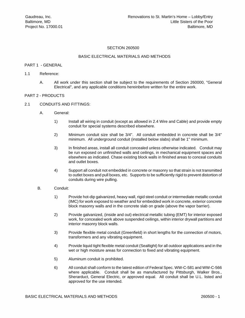
Gaudreau, Inc. Renovations to St. Martin’s Home – Lobby/Entry
Baltimore, MD Little Sisters of the Poor
Project No. 17000.01 Baltimore, MD
BASIC ELECTRICAL MATERIALS AND METHODS 260500 - 1
SECTION 260500
BASIC ELECTRICAL MATERIALS AND METHODS
PART 1 - GENERAL
1.1 Reference:
A. All work under this section shall be subject to the requirements of Section 260000, "General Electrical", and any applicable conditions hereinbefore written for the entire work.
PART 2 - PRODUCTS
2.1 CONDUITS AND FITTINGS:
A. General:
1) Install all wiring in conduit (except as allowed in 2.4 Wire and Cable) and provide empty conduit for special systems described elsewhere.
2) Minimum conduit size shall be 3/4". All conduit embedded in concrete shall be 3/4" minimum. All underground conduit (installed below slabs) shall be 1" minimum.
3) In finished areas, install all conduit concealed unless otherwise indicated. Conduit may be run exposed on unfinished walls and ceilings, in mechanical equipment spaces and elsewhere as indicated. Chase existing block walls in finished areas to conceal conduits and outlet boxes.
4) Support all conduit not embedded in concrete or masonry so that strain is not transmitted to outlet boxes and pull boxes, etc. Supports to be sufficiently rigid to prevent distortion of conduits during wire pulling.
B. Conduit:
1) Provide hot-dip galvanized, heavy wall, rigid steel conduit or intermediate metallic conduit (IMC) for work exposed to weather and for embedded work in concrete, exterior concrete block masonry walls and in the concrete slab on grade (above the vapor barrier).
2) Provide galvanized, (inside and out) electrical metallic tubing (EMT) for interior exposed work, for concealed work above suspended ceilings, within interior drywall partitions and interior masonry block walls.
3) Provide flexible metal conduit (Greenfield) in short lengths for the connection of motors, transformers and any vibrating equipment.
4) Provide liquid tight flexible metal conduit (Sealtight) for all outdoor applications and in the wet or high moisture areas for connection to fixed and vibrating equipment.
5) Aluminum conduit is prohibited.
6) All conduit shall conform to the latest edition of Federal Spec. WW-C-581 and WW-C-566 where applicable. Conduit shall be as manufactured by Pittsburgh, Walker Bros., Sherarduct, General Electric, or approved equal. All conduit shall be U.L. listed and approved for the use intended.

Gaudreau, Inc. Renovations to St. Martin’s Home – Lobby/Entry
Baltimore, MD Little Sisters of the Poor
Project No. 17000.01 Baltimore, MD
BASIC ELECTRICAL MATERIALS AND METHODS 260500 - 2
7) Provide polyvinylchloride (PVC) schedule 40 conduit for underground direct burial below concrete slabs and exterior underground installation.
C. Fittings:
1) All fittings to match conduit material and to be suitable for the purpose intended.
2) Provide expansion fittings with bonding jumpers where conduits cross expansion joints or where otherwise required to compensate for thermal expansion and contraction.
3) Fasten rigid steel and IMC conduit with threaded galvanized steel fittings, double locknuts and insulating bushings.
4) Fasten EMT conduit with compression type fittings made from galvanized steel or malleable iron. Set screw type fittings will not be allowed.
5) Fasten liquid-tight conduit with fittings incorporating a threaded ferrule, nylon sealing ring, and steel or malleable iron nut and body.
6) Fitting shall be as manufactured by Crouse Hinds, Appleton, T & B Efcor, or approved equal. All fittings shall be approved for grounding and suitable for the intended use.
D. Installation:
1) Keep all conduits minimum 6" away from hot water pipes or other hot surfaces above 77 degrees F.
2) Install all conduits parallel and perpendicular to walls, structure members, ceilings and interior surfaces; install plumbing.
3) Provide a nylon pull line inserted in each conduit to be left empty.
4) Make angle bends in exposed runs of conduits with manufactured elbows, screw jointed conduit fittings or conduit bent to radius of manufactured elbows.
5) Install concealed conduits in as direct line as possible with a minimum number of bends, using long radius elbows and bends.
6) Use capped bushings or "push penny" plugs to prevent foreign matter from entering the conduit system during construction.
7) Clean and plug or cap all conduits left empty for future use.
8) Where exposed conduit is installed on water bearing walls, provide stand-off brackets to maintain a minimum 1/2" air space between the conduit and the mounting surface.
9) Lubricants for pulling wires shall be approved for use with the wires and conduits installed.
10) Wherever the galvanized surface of a conduit is damaged, the surface shall be touched-up. Similar treatment shall be provided for all exposed conduit threads. Touch-up shall be bituminous paint for concealed conduit and alkyd primer where exposed.
11) All conduits in floor construction shall be installed in the concrete slab above the vapor barrier.

Gaudreau, Inc. Renovations to St. Martin’s Home – Lobby/Entry
Baltimore, MD Little Sisters of the Poor
Project No. 17000.01 Baltimore, MD
BASIC ELECTRICAL MATERIALS AND METHODS 260500 - 3
E. Supports:
1) All parts and hardware used for support of equipment, conduits and fittings, shall be galvanized.
2) Support single runs of suspended feeder conduit with "Kindorf" C-149 or C-150 adjustable hangers using threaded rods attached to the structure above in an approved manner.
3) Support groups of suspended conduits run in parallel on trapeze hangers constructed of "Kindorf" channels with C-105 conduit straps and suspended with threaded rods attached to the structure above in an approved manner. No tie wires or building wire shall be used for strapping conduits.
4) Support surface runs of conduit using one hold pipe straps or two hold pipe straps. Strap spacing maximum 6 ft. on centers.
5) Fasten pipe straps and hangers to concrete using inserts or expansion bolts and to hollow masonry using toggle bolts. Wooden plugs and shields will not be permitted. All supports in bar joist construction shall be attached to the top cord of the joists using suitable clamps approved for the purpose.
6) Support conduits from joists and beams using clamps and/or Caddy clips approved for the purpose.
2.2 OUTLET BOXES:
A. All outlet switch and junction boxes, etc., shall be sherardized or galvanized stamped steel as manufactured by Steel City, Raco, Appleton, or General Electric. Provide a box at each outlet, switch, etc. Sectional malleable iron or pressure cast boxes shall not be used.
B. Outlet boxes in concrete construction shall be octagonal, two piece type or nonmetallic of sufficient depth to keep conduits not closer than 1" to surface.
C. No "thru-wall" boxes shall be used in partitions.
D. Switch and receptacle boxes in masonry partitions and walls shall be square cornered tile wall boxes 3-1/2" deep, or 4" square boxes with raised tile wall device covers. The device covers shall be of extra depths required to suit the block or brick construction in which they are placed. The boxes shall be firmly secured in place, plumb, level, and with front of device cover not more than 1/4" back from finished wall surface.
E. Wall and partition mounted outlets for low-voltage systems shall be same as specified above for switches and receptacles. For communication service the outlets shall be a raised tile wall device ring, single gang for telephone or data.
F. Special outlet boxes where required for other low voltage systems shall be provided in accordance with the equipment manufacturer's requirements of the various systems as hereinafter specified.
G. All outlet boxes used for supporting fixtures shall be furnished with malleable iron fixture studs of "no-bolt" type secured by locknut. Provide support for boxes occurring in suspended ceilings. Outlets in ceilings shall be supported independent of ceiling construction. Outlets in suspended ceilings shall not be supported from ceiling construction.
H. All boxes whether outlet, junction, pull or equipment, shall be furnished with appropriate covers.

Gaudreau, Inc. Renovations to St. Martin’s Home – Lobby/Entry
Baltimore, MD Little Sisters of the Poor
Project No. 17000.01 Baltimore, MD
BASIC ELECTRICAL MATERIALS AND METHODS 260500 - 4
2.3 JUNCTION AND PULL BOXES:
A. Junction and pull boxes shall be furnished and installed as shown or where required to facilitate pulling of wires or cables. Such boxes shall be installed in accessible locations and shall be approved by the Engineer. All boxes for concealed work shall be constructed of #12 gauge USS galvanized sheet steel minimum, unless otherwise specified or indicated and provided with mounting brackets and flat screw covers, secured in position by round head brass or stainless steel 300 grade machine screws. Boxes for exterior work shall be cast aluminum or non-metallic (PVC) with weatherproof conduit connections. Gasketed cover plates shall be furnished for outdoor installations.
2.4 WIRE AND CABLE (600 Volt):
A. Building wire, unless otherwise indicated, shall be 600 volt, 90 degree C rated, type THHN/THWN-2 insulation for interior use. Conductors shall be sized and run as indicated. Conductors shall be soft drawn copper of not less than 98% conductivity. No Romex or BX cable is permitted. Type MC (metal clad) cable shall be permitted for all branch circuits rated 60 amperes or less where concealed above dropped ceilings, within drywall partitions and above the joists in exposed ceiling areas. All wiring in exposed ceiling areas shall be in conduit when run below the joist level.
B. No wire smaller than number twelve (12) AWG shall be used unless otherwise indicated. The wire size indicated in the homerun shall be used throughout the circuit. Conductors shall be continuous from outlet to outlet and from terminal board to point of final connection, and no splice shall be made except within outlet or junction boxes. All conductors shall be of the sizes as indicated. All wires number eight (8) AWG and larger shall be stranded. Where homeruns are combined by the contractor, individual neutrals shall be used for each circuit. No multi-wire branch circuits with shared neutral conductors shall be installed. The Contractor shall make wiring connections of all electrical equipment requiring electric service. Wires and cables shall be as manufactured by Southwire, AFC, Plastic Wire & Cable Corporation, Okonite Company, General Electric or equivalent.
C. Control wiring shall not be less than Number Fourteen (14) AWG, unless specified otherwise, and shall be color coded using terminal blocks shall be suitable tagged for ease in identification and tracing of circuits. Identification tags shall be engraved fiber or plastic type, subject to acceptance. Wires shall be numbered and coded, using Brady "Quicklabels", or equivalent.
D. A color coding system, as listed below, shall be used for throughout the building's network of feeders and circuits and used as a basis of balancing the load. Selection shall be based on applicable work covered by this Contract. Follow existing building wiring color codes where they exist.
System Phase A Phase B Phase C Neutral Ground
120/208V Black Red Blue White Green
E. All control wiring shall be color coded with wires of colors different from those to designate phase wires.
F. Wiring for 120 volt general branch circuit work as follows, unless otherwise indicated:
Home Run Length Circuit Length and Wire Size and Wire Size
0' - 75' #12 0' - 100' #12

Gaudreau, Inc. Renovations to St. Martin’s Home – Lobby/Entry
Baltimore, MD Little Sisters of the Poor
Project No. 17000.01 Baltimore, MD
BASIC ELECTRICAL MATERIALS AND METHODS 260500 - 5
75' - 100' #10 100' & Up #10
Circuit length as given above shall be the wire length between the first and last outlet on the circuit. Home run length as given above shall be the wire length between the first outlet and the panelboard.
2.5 SPLICES (BELOW 600 VOLTS):
A. Joints of 10 AWG and smaller shall be made with properly insulated solderless type pressure connectors. Where stranded conductors or multiple solid conductors are connected to terminals, solderless lugs manufactured by Thomas & Betts Company shall be used. "Scotchlock" electrical spring connectors shall be used on all other splices and connection, except that on joints and splices of lighting fixtures Ideal "Wirenuts" with threaded metal inserts may be used.
B. Joints of #8 AWG and larger in power and lighting circuits shall be of the type indented into the conductor by means of a band or hydraulic pressure tool. Connectors shall be Burndy "Hi-Dent", T & B "Staq-Kon", or equivalent. Connectors for control wiring shall be Burndy "Hy-Lug" or equivalent.
2.6 DISCONNECTS (SAFETY SWITCHES):
A. Furnish and install safety switches where indicated and as required for motor outlets or other equipment. Switches shall be of size, number of poles and fused or non-fused, as required for job conditions, as shown on the drawings and as required by the National Electrical Code. Class RK-1 current limiting fuses shall be used in all fused switches. Fused switches shall be furnished with rejection clips so that only class RK-1 current limiting fuses can be installed.
B. Switches shall be equipped with fuse contacts and jaws which insure positive fuse and jaw contact by means of reinforcing spring clips or other approved means. All current carrying parts shall be silver plated. Hinges shall be non-current carrying. Switches shall be so designed that they can be locked in either open or closed position.
C. All safety switches shall be NEMA 1 enclosure Type "HD" quick-make, quick-break, and have interlocking cover with handle that may either be front or side operating with a padlocking provision, as manufactured by Square "D" or approved equal. Provide NEMA 4X watertight enclosures where used in the wet areas and NEMA type 3R where installed outdoors exposed to the weather.
2.7 MOTOR STARTERS:
A. Provide starters, H-O-A switches, pilot lights and control wiring as indicated on the drawings, or specified herein. Where starters are provided in existing motor control centers they shall match the existing manufacturer and other starter types. All temperature control wiring and components shall be furnished by the mechanical contractor. All variable frequency drives (VFD) shall be furnished by the mechanical contractor.
B. Thermal manual motor starting switches shall be provided for all fractional horsepower, single phase motors, unless otherwise specified. Manual motor starters shall be of the snap-switch type containing thermal overload protection and a self-indicating trip-free handle. Starting switches shall be combined with a three-position hand-off-automatic selector switch when motor is controlled automatically. (Refer to mechanical equipment schedules and control sequencing.) Pilot indicating light shall be mounted in all starter enclosures where noted. The starters shall be Square D Company, Class 2510, Allen Bradley Bulletin 600, or approved equal. Enclosures shall be NEMA 1 for interior use.

Gaudreau, Inc. Renovations to St. Martin’s Home – Lobby/Entry
Baltimore, MD Little Sisters of the Poor
Project No. 17000.01 Baltimore, MD
BASIC ELECTRICAL MATERIALS AND METHODS 260500 - 6
C. Magnetic motor starters shall be provided for all three phase motors unless otherwise specified. Motor starters shall be 3 pole, 60 hertz, full-voltage, magnetic type with NEMA 1 enclosures, as required. Starters shall be provided with three element overloads. Where shown, starters shall be of the combination fused or unfused disconnect type as noted. Starters shall be equipped with hand-off-automatic selector switch, a pilot indicating light and auxiliary contacts. Each magnetic starter shall have a 120 volt coil, an individual control power transformer and a fuse for protection of control wiring. Starters shall be Square D Company, Class 8536 and Class 8538 as required or approved equal.
2.8 WIRING DEVICES:
A. The following wiring devices shall be furnished and installed where called for on the drawings. Miscellaneous items not included below shall be Underwriters' Laboratories Standard conforming to the N.E.C. All devices shall be of the same manufacturer. Devices shall be Arrow Hart, General Electric, Circle F, or Hubbell, and equal to the following:
1) Wall Switches: Toggle switches shall be of the silent mechanical type rated 20 ampere, 120/277 volt A.C. Three and four-way switches shall be of the same manufacturer and grade.
2) Receptacles: Receptacles for wall outlets shall be rated 20 ampere, 125 volts, duplex, three-wire with third pole grounded.
3) Special Wiring Devices: Shall be provided as shown on the drawings.
4) Ground, phase and neutral conductors shall be pig-tailed in outlet boxes or multi-outlet assembly (plugmold) for each receptacle so that the ground and the electrical service will not be disturbed to other receptacles on the same circuit if one receptacle is removed.
5) Device Plates: A device plate shall be provided for each outlet requiring one. All plates shall be manufactured by Arrow Hart or Hubbell of satin finish, .040 stainless steel, type 430, except where specifically called for to be otherwise in these specifications. Telephone/data plates shall be similar except shall be blank.
6) Where wiring devices are used outdoors they shall be mounted in gasketed, cast metal boxes with heavy duty, cast metal protective cover that will permit the cord to be plugged in while the protective cover is closed (Intermatic WP1010MC and WP1010HMC series). In GMP lab areas where wiring devices are noted to be weatherproof they shall be die cast, zinc with powder coated white finish, spring lids that stay open at 90 degrees using stainless steel lid springs and mounting screws. Covers shall include a gasket between the cover and the wall box. Weatherproof covers shall be manufactured by Mulberry Metal Products or equal.
2.9 OCCUPANCY SENSOR LIGHTING CONTROLS:
A. An occupancy sensor control system shall be provided for the overhead lighting system in the building including all private offices and individual rooms. The sensor switches shall be dual technology type incorporating both passive infrared (PIR) and volumetric ultrasonic motion sensing. The occupancy sensor control system shall be as manufactured by The Watt Stopper, Inc. (1-800-879-8585), Leviton, Lehigh, or Cooper.
B. The contractor and occupancy sensor manufacturer shall be responsible for the layout, location and selection of the sensors, control relays, power supplies, switches, etc. to form a complete control system based on the size and layout of each room. Preliminary locations of sensors and

Gaudreau, Inc. Renovations to St. Martin’s Home – Lobby/Entry
Baltimore, MD Little Sisters of the Poor
Project No. 17000.01 Baltimore, MD
BASIC ELECTRICAL MATERIALS AND METHODS 260500 - 7
control relays are shown on the drawings for concept only and the manufacturer shall review the drawings, light fixture locations, diffusers, etc. and select the proper sensor and relay for each room application.
C. The contractor and manufacturer shall prepare and submit layout drawings (1/8" scale minimum) showing a complete layout of the system with all components, lights and control zones along with description of operation, catalog cuts of each component, field wiring diagrams and specifications for review and approval by the Architect.
D. All wiring shall be provided as recommended by the system manufacturer and shall be installed in MC cable. Interconnecting wiring between control sensors in the same control zone may be run in MC cable similar to the branch circuit wiring.
2.10 GROUNDING:
A. All electrical system grounds shall be provided as indicated on the drawings, mentioned herein and/or as required by the National Electrical Code with local Montgomery County code supplements. The following shall be solidly grounded:
1) Panelboards and distribution equipment.
2) Fused switches.
3) Wiring troughs and pull boxes.
4) Conduit system and outlet boxes.
5) Motor frames.
7) Lighting fixtures.
8) Dry Type Transformers
9) Telecommunications Ground Bus
B. Provide equipment grounding conductors in all raceways and MC cables sized in accordance with the NEC.
2.11 MULTI-OUTLET ASSEMBLIES:
A. The electrical contractor shall furnish and install aluminum multi-outlet assembly manufactured by Wiremold Company complete with all necessary fittings, covers, dividers, wiring devices and labeling to complete the layout shown and specified on the drawings. Provide new aluminum series 4000 Wiremold above lab counters as shown and specified on the drawings.
END OF SECTION

Gaudreau, Inc. Renovations to St. Martin’s Home – Lobby/Entry
Baltimore, MD Little Sisters of the Poor
Project No. 17000.01 Baltimore, MD
ELECTRICAL DISTRIBUTION 262000 - 1
SECTION 262000
ELECTRICAL DISTRIBUTION
PART 1 - GENERAL
1.1 REFERENCE:
A. All work under this Section shall be subject to Section 260000 "General Electrical” and any applicable conditions hereinbefore written for the entire work.
1.2 ELECTRICAL SERVICE:
A. Electrical service to the site is existing and provided by BGE.
PART 2 - PRODUCTS
2.1 PANELBOARDS:
A. Furnish and install, where indicated on the drawings, automatic circuit breaker panelboards complete with enclosing cabinets. Enclosures shall be NEMA 1 for surface and recessed mounting as indicated. Panelboards and enclosing cabinets shall conform to standards established by Underwriters' Laboratories, Inc., and requirements of the NEC. Panelboards shall include double hinged (door in door), lockable covers to match existing Siemens panels. One hinged, lockable door shall be for the door accessing the breakers and one, hinged lockable door shall provide full access to the panel interior.
B. The Contractor shall balance the loading on all panelboards as closely as possible and to the satisfaction of the Architect.
C. All panelboard interiors shall be factory assembled, complete with circuit breakers as scheduled on the drawings. Interior shall be designed and assembled that any individual breaker can be replaced without disturbing adjacent units or without removing main bus, and shall employ sequence bussing. Main busses and back pans of distribution and power panelboards shall be of such design that branch circuits may be changed without additional machining, drilling, or tapping. All circuit breakers shall be quick-make and shall be trip indicating. In addition to phase and neutral bussing, provide an equipment ground bus in each panelboard bonded to the panel cabinet.
D. The circuit numbers used on the drawings are for identification and the circuit number in the panel need not necessarily correspond. Each circuit in the panel, however, shall be accurately indexed with the specific load and room/area. All existing panelboards in the building shall be provided with new circuit directories identifying all circuits and spare breakers.
E. Unless specifically designated otherwise on the drawings, panelboards shall be 277/480 volt and 120/208 volt, three phase employing bolt on breakers of not less than the symmetrical A.I.C. ratings indicated on the drawings. Furnish bolt-on, door in door Siemens type S3 (lighting and appliance) and type S4 (distribution) panelboards or equal by Square D, General Electric ,or Eaton (Cutler Hammer).
2.2 FUSES:

Gaudreau, Inc. Renovations to St. Martin’s Home – Lobby/Entry
Baltimore, MD Little Sisters of the Poor
Project No. 17000.01 Baltimore, MD
ELECTRICAL DISTRIBUTION 262000 - 2
A. Fuses for fused safety switches shall be U.L. listed class RK-1 current limiting type. All fused switches shall incorporate rejection clips to insure only current limiting replacement fuses are installed.
B. Provide Bussman "low peak" or equal by Gould-Shawmut or Littlefuse.
PART 3 - EXECUTION
3.1 SHOP DRAWINGS:
A. The Contractor shall prepare and submit complete shop drawings with equipment cuts, ratings, tripping curves, technical specifications, wiring diagrams, etc., to the Engineer for approval, prior to installation or roughing-in of any equipment.
3.2 OPERATION AND MAINTENANCE MANUALS:
A. The Contractor shall collect all operating instructions, shipping information, adjusting and maintenance manuals, parts lists, etc., pertaining to the distribution equipment and bind in the Operation and Maintenance Manuals.
3.3 SHORT CIRCUIT/COORDINATION.ARC-FLASH STUDY:
A. An independent firm, qualified and experienced in short circuit/coordination/arc-flash studies, shall perform a protective short circuit study following conditional approval of the circuit protective device shop drawings. The study shall include all existing and new distribution equipment shown in the one line diagram on the electrical drawings. The contractor shall survey all existing distribution equipment to obtain sufficient field information to prepare the study including manufacturer/model numbers of existing equipment, short circuit ratings of existing switchboards, distribution breakers, panelboards, branch circuit breakers, generator breaker, transformer impedances, cable sizes, feeder lengths, etc. The study shall be prepared by Coordinated Power Engineering (410-694-9494), Reuter Hanney (410-297-9566) or Siemens Energy and Automation (800-964-4114).
B. The study shall be prepared in accordance with ANSI and IEEE standards and shall include a one line diagram, recommendations for all adjustable trip protective device settings and substitute equipment as necessary to meet the calculated fault currents and to provide proper selective coordination of overcurrent protective devices. The contractor shall include allowances in the bid to adjust equipment selections to conform to all recommendations made in the study. The contractor shall obtain information directly from PEPCO relating to available fault currents and coordinating service entrance main protective devices. The contractor shall include recommendations for ground fault protective device settings on utility main, generator main and feeder breakers.
C. The contractor shall furnish an Arc Flash Hazard Analysis Study per the requirements set forth in NFPA 70E-Standard for Electrical Safety in the Workplace. The arc flash hazard analysis shall be performed according to the IEEE 1584 equations that are presented in NFPA 70E-2004, Annex D. The contractor of the Arc Flash Hazard Analysis shall provide a 3.5 in. x 5 in. thermal transfer type label of high adhesion polyester for each equipment location analyzed. All labels shall be based on recommended overcurrent device settings and shall be field applied on all equipment after the results of the analysis have been presented to the Architect and approved and after any system changes, upgrades or modifications have been incorporated in the system.

Gaudreau, Inc. Renovations to St. Martin’s Home – Lobby/Entry
Baltimore, MD Little Sisters of the Poor
Project No. 17000.01 Baltimore, MD
ELECTRICAL DISTRIBUTION 262000 - 3
END OF SECTION

Gaudreau, Inc. Renovations to St. Martin’s Home – Lobby/Entry
Baltimore, MD Little Sisters of the Poor
Project No. 17000.01 Baltimore, MD
LIGHTING 265000 - 1
SECTION 265000
LIGHTING
PART 1 - GENERAL
1.1 SCOPE:
A. Furnish and install a complete lighting fixture for each lighting fixture symbol shown on the drawings, of the type and quality described herein and in the lighting fixture schedule on the drawings. Fixtures shall be installed complete with lamps of the wattage indicated, sockets, housing, ballast (if required), shades, diffusers, supports, etc., and wired for operation.
1.2 REQUIREMENTS:
A. The Contractor shall be completely responsible for the proper and accurate position of sockets in all fixtures so that the filament of the size and type lamps specified, when installed in such sockets, will be in correct relation to the center of the fixture as specified by the manufacturer of the various lighting fixtures and glass units specified.
B. All sockets shall be approved by Underwriters' Laboratories, Inc. Fluorescent sockets shall be thru-slot type and incandescent lamp sockets shall be 250 volt code standard, medium base for lamps up to 200 watts inclusive and Mogul base for lamps 300 watts and larger. They shall be of Bryant, Hubbell, Arrow, Benjamin, General Electric or approved equal.
C. All fixtures shall be wired for polarized system with one wire in each fixture to be distinctly marked for its entire length. Wire shall bear the label of approval of the Underwriters Laboratories, Inc. Fixture wiring for fluorescent fixtures and branch circuit wiring in fluorescent fixture channels shall be type THHN (90 degree C. rated). All channels in fluorescent lighting fixtures shall be approved for through wiring. Type AF wire shall only be used for interior incandescent fixture wiring.
D. All fixtures shall be in accordance with all local Municipal and State Requirements governing same and shall be U.L. approved.
E. All plastic diffusers shall be 100 percent virgin acrylic (nominal 1/8 inch thick) and all Lexan diffusers shall be Lexan Type MR-4000, or equal.
F. Each fixture shall be completely equipped with lamps of the size, type, wattage and shape indicated and specified. All lamps shall be manufactured by the General Electric Co., Phillips, Westinghouse Mfg., Co., Sylvania or approved equal, of standard schedule make Exact voltage shall be checked before ordering fixtures.
G. Fluorescent lamps shall be as specified in the lighting fixture schedule on the drawings. Lamps shall be T8 having bipin bases. Lamps shall be operated on electronic, high frequency instant start ballasts, as specified hereinafter, specifically designed for 265 ma., T8 lamps. The ballast and lamp combination shall be discrete.
H. All fluorescent lighting fixtures shall have energy saving, solid state electronic ballasts as manufactured by Advance, Magnitek or approved equal. Electronic ballasts shall be less than 10% total harmonic distortion (THD).

Gaudreau, Inc. Renovations to St. Martin’s Home – Lobby/Entry
Baltimore, MD Little Sisters of the Poor
Project No. 17000.01 Baltimore, MD
LIGHTING 265000 - 2
I. At the location of outlets indicated on the various drawings, the type of fixture required is designated by a type letter. All fixtures shall be furnished in the quantities, sizes and types as indicated on the drawings.
J. Recessed fluorescent fixtures in ceilings may not be supported from the suspended ceiling construction. Box and fixture supports shall be fastened securely to structural slab or bar joist except as noted. Where fixtures are surface mounted, neat holes shall be cut in the hung ceilings as required for the fixture supports. All support hangers, channels, bolts, etc., shall be galvanized or Galv-Krom.
K. Provide adequate supports for all fixtures separate from the suspended ceiling system. Contractor shall furnish and install all necessary accessories, as required, to support the fixtures. Provide a minimum of two (2) galvanized steel #12 gauge hanger wires for the support of each recessed fixture. Fluorescent fixtures shall be provided with four (4) hanger wires, one on each corner independently to the structure above.
L. All exterior hardware such as screws, nuts, washers, anchor bolts, etc., shall be rustproof.
M. All fixtures shall be fully protected until final acceptance.
N. All modifications made to fixtures shall be done by the manufacturer in the shop. Field modifications will not be accepted.
END OF SECTION

Gaudreau, Inc. Renovations to St. Martin’s Home – Lobby/Entry
Baltimore, MD Little Sisters of the Poor
Project No. 17000.01 Baltimore, MD
FIRE DETECTION AND ALARM 283100 - 1
SECTION 283100
FIRE DETECTION AND ALARM
PART 1 - GENERAL
1.1 REFERENCE:
A. All work under this Section shall be subject to Section 260000, "General Electrical” and any applicable conditions hereinbefore written for the entire work.
1.2 SCOPE:
A. The existing building fire alarm system shall remain and be reconfigured as required to accommodate the new floor plan layout and building uses.
B. The Contractor shall become fully familiar with the existing building fire alarm system, including all main panels, extender panels, annunciator panels, wiring, initiating appliances, and signaling appliances. This equipment shall be reused to the extent possible; new equipment, wiring, and appliances shall be provided as required. All new equipment shall match existing.
C. Furnish and install all material, labor and incidentals necessary for the complete reconfiguration, installation, and successful operation of the Fire Alarm System.
PART 2 – PRODUCTS
2.1 FIRE ALARM SYSTEM:
A. DESCRIPTION:
1. This section of the specifications includes the reconfiguration of the existing addressable, microprocessor-controlled fire alarm system. To the extent possible, the existing fire alarm system components shall be reused. New/additional equipment shall include, but not be limited to, alarm initiating devices, alarm notification appliances, auxiliary control devices, annunciators, power supplies, booster panels, remote lobby annunciator panel, communicator and wiring as shown on the drawings and specified herein.
2. The contractor shall fully coordinate the reconfiguration of the fire alarm system with the Fire Marshal; the system shall remain operational during construction. The existing system is Class A which shall require the use of supply and return wiring for all devices.
B. SCOPE:
1. Basic System Functional Operation
a. Alarm Detection: When an alarm condition is detected by one of the system initiating devices, the following functions shall immediately occur:
1. The System Alarm LED on the panel shall flash and a local sounding device in the panel shall be activated.
2. The Panel LED for the initiating zone in alarm shall flash and the

Gaudreau, Inc. Renovations to St. Martin’s Home – Lobby/Entry
Baltimore, MD Little Sisters of the Poor
Project No. 17000.01 Baltimore, MD
FIRE DETECTION AND ALARM 283100 - 2
custom zone description shall be displayed on the remote annunciator.
3. All audible signals shall sound and all visible signals shall flash throughout the building until silenced at the control panel or the remote annunciator. All automatic programs assigned to the alarm point shall be executed and the associated relays activated.
4. All door holders, where applicable, shall release.
5. An individual zone address shall appear on the LCD readout panel and describe the device and zone in alarm.
b. Alarm condition initiated by a duct smoke detector shall, in addition to 2.2 B1a above, shutdown its respective air handling system.
c. Operation of a tamper switch shall, in addition to 2.2 B1a above, transmit a supervisory signal to the appropriate monitoring agency.
d. System Trouble Detection: When a trouble condition is detected by one of the system initiating or notification circuits, the following functions shall immediately occur:
2. The Panel System Trouble LED shall flash and a local sounding device in the panel shall be activated. This sound shall be distinct from the alarm sound.
3. The trouble LED for the corresponding initiating or notification circuit shall flash on its respective module. If the trouble condition is caused by a CPU or Power Supply Trouble, the corresponding LED on the CPU shall flash.
4. A trouble signal shall be transmitted to the appropriate monitoring agency.
C. SUBMITTALS:
1. General:
a. Ten copies of all submittals shall be submitted to the Architect for review.
b. In addition to the general submittal process, three complete sets of submittals and three complete sets of fire alarm plan drawings shall be provided for the review and approval by the local fire marshal. An approved set of the submitted documents shall be at the job site for the use of the fire marshal during their inspection.
2. Shop Drawings:
a. Include manufacturer's name(s), model numbers, ratings, power requirements, battery capacity, equipment layout, device arrangement, and complete wiring point-to-point diagrams. The fire alarm vendor shall prepare a set of CAD plan drawings to 1/8” scale showing all fire alarm components in the building including candela ratings of all visual devices. The plan drawings prepared by the vendor shall adjust any device locations, candela ratings, etc. as required to meet local and national fire codes. Submit to local fire marshal for approval. Show annunciator layout and main control panel

Gaudreau, Inc. Renovations to St. Martin’s Home – Lobby/Entry
Baltimore, MD Little Sisters of the Poor
Project No. 17000.01 Baltimore, MD
FIRE DETECTION AND ALARM 283100 - 3
module layout, configurations and terminations.
3. Manuals:
a. Submit complete operating and maintenance manuals listing the manufacturer's name(s) including technical data sheets (with model numbers to be used indicated). Wiring diagrams shall indicate terminals and the interconnections between the items of equipment. Provide a clear and concise description of operation which gives, in detail, the information required to properly operate the equipment.
D. WARRANTY:
1. All work performed and all material and equipment furnished under this contract shall be free from defects and shall remain so for a period of at least one (1) year from the date of acceptance.
E. APPLICABLE PUBLICATIONS:
1. The publications listed below form a part of this specification. The publications are referenced in text by the basic designation only.
a. National Fire Protection Association (NFPA) - USA: No. 72 National Fire Alarm Code No. 101 Life Safety Code
b. Underwriters Laboratories Inc. (UL) Publications: Fire Protection Equipment Directory(Latest Addition).
c. ADA- American's with Disabilities Act-1990.
d. The International Building Code (Latest Edition)
e. Local and State Building Codes
f. All requirements of the Authority Having Jurisdiction (AHJ).
F. MAIN FIRE ALARM CONTROL PANEL
1. The contractor shall reuse and reconfigure the existing panels and associated accessories to meet the requirements of the local fire marshal.
G. BATTERIES
1. Exiting fire alarm system batteries, in main and extender panels, shall be tested and replaced as required. New batteries shall be sealed Gel-Cell acid type, 12 volt nominal (two minimum required). Battery shall have sufficient capacity to power the fire alarm system for not less than twenty four hours plus 10 minutes of alarm upon a normal AC power failure or as dictated by the local fire marshal.
H. SYSTEM COMPONENTS:
1. Programmable speakers shall be field programmable to provide slow whoop, continuous or interrupted tones, with an output sound level of at least 90 dBA measured 10 feet from the device.
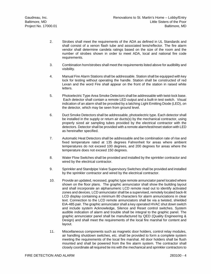
Gaudreau, Inc. Renovations to St. Martin’s Home – Lobby/Entry
Baltimore, MD Little Sisters of the Poor
Project No. 17000.01 Baltimore, MD
FIRE DETECTION AND ALARM 283100 - 4
2. Strobes shall meet the requirements of the ADA as defined in UL Standards and shall consist of a xenon flash tube and associated lens/reflector. The fire alarm vendor shall determine candela ratings based on the size of the room and the number of strobes shown in order to meet ADA, local and national fire code requirements.
3. Combination horn/strobes shall meet the requirements listed above for audibility and visibility.
4. Manual Fire Alarm Stations shall be addressable. Station shall be equipped with key lock for testing without operating the handle. Station shall be constructed of red Lexan and the word Fire shall appear on the front of the station in raised white letters.
5. Photoelectric Type Area Smoke Detectors shall be addressable with twist-lock base. Each detector shall contain a remote LED output and a built-in test switch. Visual indication of an alarm shall be provided by a latching Light Emitting Diode (LED), on the detector, which may be seen from ground level.
6. Duct Smoke Detectors shall be addressable, photoelectric type. Each detector shall be installed in the supply or return air ducts(s) by the mechanical contractor, using properly sized air sampling tubes provided by the electrical contractor with the detectors. Detector shall be provided with a remote alarm/test/reset station with LED as hereinafter specified.
7. Automatic Heat Detectors shall be addressable and be combination rate of rise and fixed temperature rated at 135 degrees Fahrenheit for areas where ambient temperatures do not exceed 100 degrees, and 200 degrees for areas where the temperature does not exceed 150 degrees.
8. Water Flow Switches shall be provided and installed by the sprinkler contractor and wired by the electrical contractor.
9. Sprinkler and Standpipe Valve Supervisory Switches shall be provided and installed by the sprinkler contractor and wired by the electrical contractor.
10. Provide an updated, recessed, graphic type remote annunciator panel located where shown on the floor plans. The graphic annunciator shall show the building layout and shall incorporate an alphanumeric LCD remote read out to identify activated zones and devices. LCD annunciator shall be a supervised, remotely located back-lit LCD display containing a minimum 80 characters for alarm annunciations in clear text. Connection to the LCD remote annunciators shall be via a twisted, shielded EIA-485 pair. The graphic annunciator shall a key operated HVAC shut down switch and include system Acknowledge, Silence and Reset control switches. System audible indication of alarm and trouble shall be integral to the graphic panel. The graphic annunciator panel shall be manufactured by QED (Quality Engineering & Design) and shall meet the requirements of the local fire marshal for content and layout.
11. Miscellaneous components such as magnetic door holders, control relay modules, air handling shutdown switches, etc. shall be provided to form a complete system meeting the requirements of the local fire marshal. All door holders shall be flush mounted and shall be powered from the fire alarm system. The contractor shall closely coordinate all required tie ins with the mechanical and sprinkler contractors to

Gaudreau, Inc. Renovations to St. Martin’s Home – Lobby/Entry
Baltimore, MD Little Sisters of the Poor
Project No. 17000.01 Baltimore, MD
FIRE DETECTION AND ALARM 283100 - 5
assure all voltages (smoke/fire dampers) and contact closure configurations (air handling unit shut downs), etc. are correct.
12. Provide remote appliance power supply panels (booster panels) with battery backup located in electrical and mechanical equipment spaces as required to accommodate wiring of the system components.
I. INSTALLATION:
1. Installation shall be in accordance with the NEC, NFPA 72, local and state codes, as shown on the drawings, and as recommended by the major equipment manufacturer.
2. All conduit, junction boxes, conduit supports and hangers shall be concealed in finished areas and may be exposed in unfinished areas. Smoke detectors shall not be installed prior to the system programming and test period. If construction is ongoing during this period, measures shall be taken to protect smoke detectors from contamination and physical damage.
J. TEST:
1. Provide the service of a competent, factory-trained engineer or technician authorized by the manufacturer of the fire alarm equipment to technically supervise and participate during all of the adjustments and tests for the system.
K. FINAL INSPECTION:
1. At the final inspection a factory trained representative of the manufacturer of the major equipment shall demonstrate that the systems function properly in every respect.
L. INSTRUCTION:
1. Provide instruction as required to the building personnel and fire and safety personnel. "Hands-on" demonstrations of the operation of the system shall be provided.
M. WIRING:
1. The Contractor shall furnish and install non-specified equipment required to make each system fully functional as per stated intent, without additional cost. This shall include major components, if required.
2. The installation and design of the fire alarm and detection system shall comply with NFPA Standard 72.
3. Install fire alarm and detection system wiring in conduit (1/2 inch minimum). Where permitted by the local fire marshal and electrical codes, the contractor may use fire alarm MC cable for work concealed above dropped ceilings and within drywall partitions.
4. Minimum wire size: No. 18 AWG solid copper for initiation and annunciator circuits: No. 14 AWG solid copper for indicating circuits: No. 12 AWG solid copper for 120 volts circuits.

Gaudreau, Inc. Renovations to St. Martin’s Home – Lobby/Entry
Baltimore, MD Little Sisters of the Poor
Project No. 17000.01 Baltimore, MD
FIRE DETECTION AND ALARM 283100 - 6
5. No wiring other than that directly associated with the fire alarm or auxiliary functions shall be permitted in the fire alarm conduits. Wiring splices are to be avoided to the extent possible. Transposing or changing color coding of wires shall not be permitted. All conductors in conduit containing more than one shall be color coded and be labeled on each end with "E-Z Markers" or equivalent. All fire alarm junction boxes shall be painted red. Conductors in cabinets shall be carefully formed and harnessed so that each drops off directly opposite to its terminal. Cabinet terminals shall be numbered and coded. All controls, functions switched, etc. shall be clearly labeled on all equipment panels.
6. Quantity and location of sprinkler waterflow and valve supervisory switches will vary as per approved sprinkler system layout. Refer to the approved sprinkler system shop drawings for quantities and locations prior to rough-in.
7. Mount end-of-line device for each indicating and indicating circuit in a separate box located not more than 6 feet above the finished floor. Device shall be mounted on a terminal strip attached to the box cover with an engraved phenolic plate.
8. Each detector in a duct above a ceiling, mounted in a rooftop unit or otherwise concealed from direct view shall be provided with a remote alarm and test /reset switch accessible on the air handler in plain view. Remote units associated with concealed smoke detectors in air handling units shall be mounted in plain view, on the exterior surface of or adjacent to the air handling units.
PART 3 - EXECUTION:
3.1 PROJECT ACCEPTANCE AND MAINTENANCE:
A. Testing procedures for the acceptance of the alarm and detection system shall be conducted in accordance with provisions of NFPA 72.
B. As-built drawings in conformance with the provision of NFPA 72 shall be provided prior to the acceptance test. Three sets of maintenance manuals and a complete acceptance test report shall be provided.
C. The Contractor shall guarantee labor, materials and equipment provided under this contract against defects for a period of 1 year after the date of the final acceptance of this work by the tenant. Service during the guarantee period shall be provided within 8 hours after notification and all repairs shall be effective within 24 hours after notification. Should the contractor fail to comply with the above requirements, the tenant will then have the option to make the necessary repairs and back charge the contractor without any loss warranty or guarantee as provided by the contract documents.
D. The contractor shall include in the contract price, independent certification of the completed fire alarm system meeting the requirements of the local Montgomery County fire marshal.
END OF SECTION