Embed Size (px)
Citation preview
ST150 SAFECOM Central StationOperation and Installation Guide
ST150
ST150 SAFECOM Central Station Operation Manual4998122249B Page 2 © 2002 Radionics
ST150Contents
ST150 SAFECOM Central Station Operations Manual© 2002 Radionics Page 3 4998122249B
Table of Contents1. System Overview .............................................................5
1.1. SAFECOM System Overview ....................................51.2. SAFECOM ST150 Receiver Software Overview .......51.3. SAFECOM Base Station Hardware Requirements....61.4. SAFECOM Client Site Communicators Overview......61.5. SAFECOM SC9000 Receiver Software Requirements.............................................................7
2. System Operation ............................................................92.1. SAFECOM System Start-Up Procedure ....................92.2. Operator Log-In Procedures ......................................9
2.2.1. To Log In an Operator........................................92.3. SAFECOM Main System Status Menu Screen........10
2.3.1. System Date and Time ....................................102.3.2. Operator Prompts ............................................102.3.3. Radio Status Window.......................................112.3.4. Command Window...........................................112.3.5. Record of Events Window................................112.3.6. Operator Window .............................................12
2.4. Entering User Control Data......................................122.4.1. To Enter or Edit Data in a User Control ...........122.4.2. To Save Changes to User Controls .................12
2.5. Available SAFECOM Keyboard Commands............122.6. SAFECOM Operating Modes...................................132.7. Radio Communicator Account Numbers..................14
3. Installing and Communicating with RadioCommunicators......................................................................15
3.1. Selecting/Polling a Radio Communicator.................153.2. Bringing a New SAFECOM Unit Online ...................153.3. Removing a Radio Communicator Account from the SC9000 ....................................................................16
3.3.1. To Remove a Radio Communicator Account from the SC9000 Receiver..............................16
3.4. Temporarily Stop Communications with a Radio Communicator -Sending a Manual Deactivate Command from the SC9000 ....................................173.5. Changing Radio Communicator Account Numbers .17
4. Radio Communicator Procedures................................194.1. SC2104 ....................................................................19
4.1.1. SC2104 Alarm Panel Backup Communicators Overview ..........................................................194.1.2. Programming an SC2104 Account into the SC9000 ............................................................194.1.3. Remote Status Display – the SC2104 Radio Communicator’s Response to a Manual “Poll” by the Operator ................................................224.1.4. Controlling an SC2104 Radio Communicator ...23
4.2 SC8016 .....................................................................244.2.1 SC8016 Full Data Transfer Communicator Overview ..........................................................244.2.2 Programming an SC8016 Account into the SC9000 ............................................................254.2.3 Remote Status Display-the SC8016 Radio Communicator’s Response to a Manual “Poll” by the Operator. ................................................27
5. System Commands........................................................295.1. Using the F2=Utilities System Functions .................29
5.1.1. F1=Set System Time and Date........................29
5.1.2. Make a Backup Copy of System and Radio Communicator Account Data ............................305.1.3. ID Startups .......................................................315.1.4. Sending an “Awaken” Command to Unprogrammed Radio Communicators ...........31
5.2. The F3=System Functions Menu Overview.............315.2.1. Using F3=System Functions Menu Page #1 ...335.2.2. Using F3=System Functions Menu Page #2 (PgDn)..............................................................33
5.3. The F4=Channel Functions Overview .....................355.4. Entering and Editing Operator Names and Passwords (F1=User Codes)...................................355.5. Alarm Panel Signal Definitions (Digital Translation (Digital XLAT)) .........................................................355.6. Entering SAFECOM Input Signal Definitions (Input Translation (Input XLAT) for SC2104) .....................365.7. Entering SAFECOM Output Control Definitions (Output Translation (XLAT) for SC8016) .................375.8. Operator Logoff Procedures (F5=Logoff).................375.9. Power Requirements for the SC9000 Computer .....375.10. SAFECOM IT1500 Field Installation Tester Unit .....375.11. SAFECOM Record of Events Messages .................385.12. How The SAFECOM Computer Displays Different Alarm Panel Format Messages................................415.13. Automation : Alarm Event Windows.........................42
ST150Contents
ST150 SAFECOM Central Station Operation Manual4998122249B Page 4 © 2002 Radionics
ST150System Overview
ST150 SAFECOM Central Station Operations Manual© 2002 Radionics Page 5 4998122249B
1. System Overview
1.1. SAFECOM System OverviewSAFECOM is a long range telemetry communications system for monitoring life safety security alarm panels that areremotely located at a customer site. The SAFECOM system uses specially designed telemetry transmitters andreceivers to provide a secure and reliable radio communications link between remote alarm panels and a CentralMonitoring Station. The information provided to the Central Monitoring Station allows security personnel or localauthorities to respond immediately and appropriately to all alarm events detected at the customer site.
The SAFECOM system is a security device for telemetry reporting of life safety Burglary and Fire alarm informationusing radio as the primary communications path. The system is also listed for commercial fire applications.
The SC9000 Receiver is the center of the entire SAFECOM network. The SC9000 Receiver uses a Compaq DeskproIBM compatible personal computer to operate the ST150 Receiver Software and provides radio communications withRadio Communicators via the RF2000 Radio Modem. Selected system events are permanently recorded on a StarMicronics dot matrix printer.
A Radio Communicator is a SAFECOM telemetry communications panel that is located at a customer site; commercialor residential. The SC9000 Receiver can supervise, monitor, and control up to 299 Radio Communicators through theSAFECOM system. The actual number of Radio Communicators usable in any specific system is determined by anumber of variables (e.g., polling rates, use of frequency by other radio systems, radio interference, etc.).The receipt ofeach message or poll that is transmitted is validated by the receiving site: the SC9000 Receiver or the RadioCommunicator. The receiving site will then transmit an acknowledge message in response.
Supervisory polling is performed by the SC9000 Receiver for each Radio Communicator to verify two-way telemetryradio communications and the operational condition of the Radio Communicator. The supervisory polling interval isindividually programmable for each Radio Communicator.
The SAFECOM system can be configured to transmit (TX) and receive (RX) on a single radio pair directly from thecentral station. This means the SC9000 communicates directly with the Radio Communicators in the field.
The SAFECOM radios can also be configured to transmit and receive on a frequency pair to a repeater located on amountain, tower, or high building in the desired coverage area. When the SAFECOM system is set up for repeatermode, the SC9000 computer communicates with the Radio Communicators through a UL Listed, SAFECOM SC801 orSC802 Data Repeater, or a commercial grade voice repeater that has been configured with a SAFECOM DP1000Controller Board. The SC801/SC802 or equivalent repeater is normally installed at a Commercial Repeater Site.
The use of a SAFECOM type or equivalent repeater significantly increases the coverage area (range). Radio areacoverage and reception ranges are also dependent on the extent of a number of environmental effects, e.g.,propagation losses due to atmospheric conditions, and the proximity of the radio transmission and reception paths todense foliage and metal structures.
The SAFECOM radio transceivers are normally available to operate in the 136-174MHz (VHF), 400-512 MHz (UHF),and 900 MHz ranges. Additional frequency ranges are available upon request. The SC9000 Receiver can communicatewith all Radio Communicators assigned to that controlling network on a single RF channel through one RF2000 RadioModem. With the installation of a SAFECOM four or eight port Expander Board, the SC9000 Receiver cancommunicate on one to eight independent and addressable RF channels. Each channel can be on a different radiofrequency, or all the channels can be on a single RF frequency. This type of configuration is for those applicationsrequiring large coverage areas with redundant paths. Each RF channel communicates through a separate RF2000Radio Modem. With multiple RF2000 modems, the SAFECOM system operates much like a large “cellular type”network, passing off the Radio Communicator messages to other repeaters when necessary.
The SAFECOM IT1500 Installation Tester tests for a standardized signal level from the remote customer site to thecentral station. Through this testing by a sales or service representative, the potential for a valid two-way radiocommunications link can be confirmed for a Radio Communicator and the SC9000 Receiver prior to its installation.
1.2. SAFECOM ST150 Receiver Software OverviewThe heart of SC9000 Receiver is the Radionics SAFECOM ST150 Software. The ST150 Receiver Software is installedon a minimum Compaq Deskpro 386N personal computer. The ST150 is a telemetry protocol technology designed toensure reliability in long range wireless communications. It continually verifies the integrity of its two-way radiocommunications link with the Radio Communicators through supervisory polling. High speed packet telemetry radiotransmissions ensure the timely receipts of polling, acknowledge and alarm messages by the SC9000 Receiver.
The ST150 gives you the ability to customize services and capabilities including variable supervisory pollingparameters, alarm priority status and remote programming and control functions. Changes or upgrades can beperformed in minutes from the SC9000 Receiver computer keyboard.
ST150System Overview
ST150 SAFECOM Central Station Operation Manual4998122249B Page 6 © 2002 Radionics
Built-in system checks allow the ST150 to deliver communications security superior to that of dial-up telephone lines.The flexible parameters of this software provide cost effective networking solutions by enabling large amounts of datato be transmitted through existing voice and data channels by packetizing that data, then transmitting at high speedsduring breaks in RF channel activity.
In this way, the system can ensure efficient radio spectrum usage while minimizing the problems associated withfrequency availability. Also, to maintain security of transmitted information, the SC9000 Receiver’s digital validationcodes inhibit unwanted tampering or subversion of the system.
1.3. SAFECOM Base Station Hardware RequirementsAn SAFECOM SC9000 Base Station is comprised of the following minimum hardware systems:
• SAFECOM SC9000 Receiver: A Compaq Deskpro 286N or 386S/20N personal computer. The computer systemmust have the following features and capabilities:
• 1.44 megabyte 3 ½" (High Density)
• 10 megabyte hard disk drive or greater
• 12 MHz clock or faster
• 1 megabyte Random Access Memory (RAM) or greater
• 2 Serial Ports
• 1 Parallel Port
• Color or Monochrome monitor
• Keyboard
• SAFECOM CM100 - CPU Monitor Board
• Star Micronics model SP300 40-column parallel printer
• SAFECOM RF2000 Radio Modem
1.4. SAFECOM Client Site Communicators OverviewThe following is a brief overview of the SAFECOM family of remote client site Radio Communicators (referred to in thecentral station software as remotes).
SC8016 Solution 16 Panel, Full data transfer, Sixteen zones, Three outputs, Radio communicator
• Full data transfer of sixteen zones on board
• Full data transfer of system status
• Three outputs for remote control, signaling, and/or automatic switching on-site
SC2104, Eight Zones, Phone-line Monitor, Radio Communicator
• Radio communications as primary, duplicate, or backup path
• Phone line monitoring (line sniffing)
• Eight zones on board for Open/Closure/Voltage/Bell Out/Ground
IT1500 SAFECOM Sales/Installation RF Tester
• Two-way radio communications tester for Radio Communicator site installations
SC801/SC802 SAFECOM Digital Data Repeater
• UL Listed for long range alarm reporting via radio
• Fully addressable to allow up to eight independent repeaters in the same coverage area
• Full battery backup and lockable cabinet, with tamper reporting via radio
ST150System Overview
ST150 SAFECOM Central Station Operations Manual© 2002 Radionics Page 7 4998122249B
1.5. SAFECOM SC9000 Receiver Software RequirementsThe SC9000 Receiver computer must utilize the following minimum software requirements:
1. Operating System: MS-DOS 3.3 or better.
2. Application Program: SAFECOM ST150 Receiver Software, version 1.00 OR HIGHER.
Note: system configurations, the personal computer MUST be dedicated to running ONLY the ST150 receiversoftware.
ST150System Overview
ST150 SAFECOM Central Station Operation Manual4998122249B Page 8 © 2002 Radionics
ST150System Operation
ST150 SAFECOM Central Station Operations Manual© 2002 Radionics Page 9 4998122249B
2. System Operation
2.1. SAFECOM System Start-Up ProcedureTo start up the SAFECOM SC9000 Base Station systems, follow the directions below:
1. RF2000 Radio Modem:
• System power is applied by plugging the 18 VAC, 40 VA transformer into a 115 VAC/60 Hz commercial ACpower receptacle (220 VAC/50 Hz for non-U.L. international configurations can be used as the dealer’sdiscretion). There is no power switch for energizing the RF2000.
• Confirm power is applied to the RF2000 by observing that the AC Power LED is illuminated.
2. Star Micronics model SP-300 40-column parallel printer:
• Turn system power on with the power switch.
• Confirm power is applied to the printer.
• Confirm printer is ready to accept text data for printing from the SC9000 Receiver by observing that the On Linelight is illuminated green. If the light is not illuminated, press the ON LINE button.
3. Compaq Deskpro 286N or 386S/20N personal computer:
• Turn computer system and monitor power on with the power switches.
• The computer system will go through a brief self-test.
At the completion of a successful self-test, the SAFECOM logo “S” will travel quickly down the screen, and the monitor willdisplay: “Press ESC to abort ST150 startup...”
• Press ESC if you wish to terminate the ST150 automatic load.
• The system will return to the DOS directory and the prompt “C:\ST150>” will be displayed.
• If ESC is not pressed by the operator, the AUTOEXEC will continue the automatic loading of the ST150 ReceiverSoftware.
• At the completion of the SAFECOM.BAT start up, the SAFECOM SC9000 Receiver Start Up Menu will bedisplayed on the monitor.
The SC9000 Receiver will automatically start polling all Radio Communicators in the field to establish a radiocommunications link. The SC9000 Receiver is in operation at this time. System messages will be displayed, printed,and/or sent to the Central Monitoring Station’s Automation software if the central station is so configured.
The system is now ready for operator login, if applicable. No operator login is required for normal system operation of theSC9000 Receiver, radio communications with all Radio Communicators, and interface with the automation software. Loginis only required when access to SC9000 System and Remote menus is required by an operator.
2.2. Operator Log-In ProceduresTo ensure that access to the System and Remote menus is limited to authorized personnel only, the SC9000 Receiverrequires an operator entry of an authorized name and password.
There are five authority levels for operator access to the SC9000 Receiver: 0, 1, 2, 3, and 4. See Entering and EditingOperator Names and Passwords (F1=User Codes) on Page 35 of this manual for more information on entering theauthorized system access operator names, passwords, and authority levels.
Login is only required when access to System and Remote menus is required by an operator. Access may be required tomonitor or edit existing Radio Communicators or add new Radio Communicators to the SC9000 Receiver.
2.2.1. To Log In an Operator• The monitor will display, “Enter your name and password below, then depress F1 to accept” and the prompts “Name:”
and “Pass:“ in the bottom right corner.
NOTE: System matches for name and password entries are not case sensitive.
• Type your authorized system access name at the name prompt and press the ENTER key. Then type your authorizedsystem access password at the pass prompt and press F1.
• The record of events message, on the left hand side of the screen, will display “**** Login YOUR NAME.”
ST150System Operation
ST150 SAFECOM Central Station Operation Manual4998122249B Page 10 © 2002 Radionics
The operator login is complete. You are now ready to access the SC9000 Receiver System and Remote menus. Thedegree of access is determined by the Authority Level assigned to your system access name and/or password.
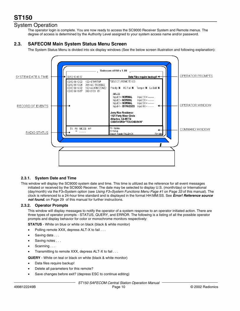
2.3. SAFECOM Main System Status Menu ScreenThe System Status Menu is divided into six display windows (See the below screen illustration and following explanation):
2.3.1. System Date and Time This window will display the SC9000 system date and time. This time is utilized as the reference for all event messages
initiated or received by the SC9000 Receiver. The date may be selected to display U.S. (month/day) or International(day/month) via the F3=System option (see Using F3=System Functions Menu Page #1 on Page 33 of this manual). Theclock is referenced to a 24-hour time standard and is displayed in the format HH:MM:SS. See Error! Reference sourcenot found. on Page 29 of this manual for further instructions.
2.3.2. Operator PromptsThis window will display messages to notify the operator of a system response to an operator initiated action. There arethree types of operator prompts - STATUS, QUERY, and ERROR. The following is a listing of all the possible operatorprompts and display behavior for color or monochrome monitors respectively:
STATUS - White on blue or white on black (black & white monitor)
• Polling remote XXX, depress ALT-X to fail . . .
• Saving data . . .
• Saving notes . . .
• Scanning . . .
• Transmitting to remote XXX, depress ALT-X to fail . . .
QUERY - White on teal or black on white (black & white monitor)
• Data files require backup!
• Delete all parameters for this remote?
• Save changes before exit? (depress ESC to continue editing)
ST150System Operation
ST150 SAFECOM Central Station Operations Manual© 2002 Radionics Page 11 4998122249B
ERROR - Blinking white on red or blinking black on white (black & white monitor)
• Expecting decimal value from XXX to XXX . . .
• Expecting hex value from XXX to XXX . . .
• Expecting ‘Y’ or ‘N’ . . .
• Shut down in progress, please wait . . .
2.3.3. Radio Status WindowThe number of RF channels displayed in the radio status window is dependent on the system configuration. The SC9000can manage a single RF channel (BOCA or single port serial board installed) or the system can drive up to eightindependent and addressable RF channels (four or eight post Digiboard installed).
• TX: Indicates the RF2000 Radio Modem, for that RF channel, is currently transmitting radio carrier wave. The symbol“ ** ” is displayed for the duration of a radio transmission.
• Each radio transmission will be reflected by a momentary blinking of the “ ** ” symbol. This reflects actual radiotransmit time.
• RX: Indicates the RF2000 Radio Modem, for that RF channel, is currently receiving radio carrier wave. The symbol “** ” is displayed for the duration of radio carrier wave detection. Receipt of a radio transmission will be reflected by amomentary blinking of the “ ** ” symbol. This reflects actual receive time; called Carrier Detect (CD).
NOTE: Display of the symbol “ ** “ is a direct duplication of the TX and RX LED indications located on the RF2000 RadioModem panel door and on the circuit board inside the panel for that RF channel,.
• Mode: Indicates the Radio Communicator that the RF2000 is transmitting to that RF channel. When the TX/RX is inthe IDLE mode, the last Radio Communicator the RF2000 had communications with will be displayed. There are 5possible indications that will be displayed in the Mode line:
“XXX”: The number of the Radio Communicator currently transmitting to or the number of the lastRadio Communicator the SC9000 had transmitted to.“FFF”: Indicates that the SC9000 is currently transmitting to or the last transmission was to a startupRadio Communicator (initialization).“- - - - “: Indicates that the SC9000 Receiver has not transmitted to or received from any RadioCommunicator since the last system startup.“BUSY”: Indicates the SC9000 Receiver has not been able to transmit for a programmed number ofseconds due to continuous RF channel activity (carrier detect - CD).“TXID”: Indicates the SC9000 Receiver is transmitting Morse Code ID for a duration as specified bythe Communications Framer.
• HP: Indicates the number of Radio Communicators that are currently about to send in alarm signals or in a HighPriority Polling Status.
2.3.4. Command WindowThis window displays the function key options that are available to the operator. The functions listed here are dependenton the authority level of the operator.
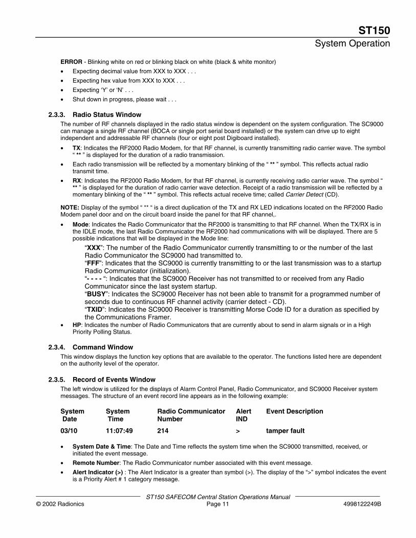
2.3.5. Record of Events WindowThe left window is utilized for the displays of Alarm Control Panel, Radio Communicator, and SC9000 Receiver systemmessages. The structure of an event record line appears as in the following example:
System System Radio Communicator Alert Event Description Date Time Number IND
03/10 11:07:49 214 > tamper fault
• System Date & Time: The Date and Time reflects the system time when the SC9000 transmitted, received, orinitiated the event message.
• Remote Number: The Radio Communicator number associated with this event message.
• Alert Indicator (>) : The Alert Indicator is a greater than symbol (>). The display of the “>” symbol indicates the eventis a Priority Alert # 1 category message.
ST150System Operation
ST150 SAFECOM Central Station Operation Manual4998122249B Page 12 © 2002 Radionics
NOTE: See SAFECOM Record of Events Messages on Page 38 for messages, description, and display behavior of allPriority Alert messages. There are messages for three Priority Alert categories: 1, 2, & 3.
• Event Description: Event messages are plain text or a combination of numeric and alpha characters that describean alarm or system condition.
2.3.6. Operator WindowThis window is utilized for the display of system and remote menus for operator monitoring, data entry and editing.
The top line of the operator window indicates the progression of menus selected by the operator within each of thecommand window options and the currently displayed menu. Additional information is displayed for specific systemoptions and menus. An “ * “ symbol is displayed in the upper left corner of the command window area to indicate that amenu can be printed (screen dump) to the Star Micronics printer. The operator may initiate the screen dump by pressingthe PRINT SCREEN key.
EXAMPLE: *ST150|REMOTE 0214|SETUP 2 SC40X0
The above example tells the operator that he/she is currently working on the second page of setup for RadioCommunicator #214, and the screen is printable, as denoted by the leading “ * “.
The operator window is also utilized for the display of advisory status messages:
• “PRINTER OFFLINE/printer online”: Indication of current printer interface status with the SC9000 Receiver.
• “AUTOMATION OFFLINE/automation online”: Indication of current Automation software interface status with theSAFECOM SC9000 Receiver.
• “Remotes active”: The number of Radio Communicators that have accounts entered into the SAFECOM SC9000
• “Remotes online”: The number of Radio Communicators that have responded with an ACK message to the last pollor message from the SC9000 Receiver.
• “Remotes off-line”: The number of Radio Communicators that are currently in an RF TROUBLE status with theSC9000 Receiver.
2.4. Entering User Control DataThere are a variety of windows, messages and options that require or allow data entry by the operator. These functionsare called User Controls.
User Controls may be commands that you can execute or data values that may be entered or modified. The SC9000highlights User Controls with a light blue colored box on color monitors and reverses video on a monochrome monitor.
2.4.1. To Enter or Edit Data in a User Control1. Position the display cursor using the ←,→,↑,↓, ENTER, or TAB keys.
2. Type the desired data into the field. It is not necessary to press the ENTER key after entering data in each UserControl field.
NOTE: The numeric keypad is functional for the entry of numerals if the NUM. LOCK key is selected.
2.4.2. To Save Changes to User Controls1. Press the ESC key. The SC9000 will then query “Save changes before exit? (depress ESC to continue editing)“ in the
operator prompt window.
2. Enter “Y” for yes or “N” for no, or press ESC to return to editing your data. A “Y” entry will update that account withthe new information. An “N” entry will dump all new information without updating the account.
2.5. Available SAFECOM Keyboard CommandsThe following keyboard commands and function keys are available for SAFECOM SC9000 system operation:
• ←↑→↓ - Increments through account numbers, or moves the display cursor to the next User Control area. The cursorkeys on both the keyboard and the numeric keypad are functional.
• Control (Ctrl) + Y - Deletes the entire line of characters from a User Control area.
• Control (Ctrl) + T - Deletes all characters from the cursor to the end of the line in a User Control area.
• ENTER - Moves the display cursor to the next User Control area. The ENTER keys on both the keyboard and thekeypad are functional.
ST150System Operation
ST150 SAFECOM Central Station Operations Manual© 2002 Radionics Page 13 4998122249B
• ESC - Allows the operator to Exit a currently displayed menu. Pressing ESC will return the display window to theprevious menu until the main System Status Menu is reached.
• F9 HELP- Place the display cursor on the desired User Control and press F9. The green Help Window for thatparticular parameter will be displayed in the Operator Display Window. Press ESC to exit the Help Window andreturn.
• F10 SILENCE- Cancels the Audio Alert Tone and Blinking from a Priority Alert event.
• PgUp/PgDn - Some account setup menus have two or more pages of information and data. Page Up and Page Downallow the operator to advance and return between the pages. Page Up and Page Down also allow the operator to Scanthrough all the active Radio Communicator accounts after pressing F1 SELECT.
• Shift +Tab - Moves the display cursor backward to the end of the previous User Control area.
• Tab - Moves the display cursor forward to the next User Control area.
• ALT+F8 – Will silence all Alarm Event Windows and Set the F3 System Enable Alarm Windows option to [N]. Thiscommand should NOT be normally be used. In the event of a catastrophic system failure as a radio modem or arepeater failure this command was included to circumvent the normal operating condition to allow the systemoperator immediate access to the system commands without the need to acknowledge a large influx of pop up AlarmWindows.
2.6. SAFECOM Operating ModesThe SAFECOM SC9000 can distinguish the location and client information of all Radio Communicators in the field. Theinitial means of identifying each Radio Communicator is by the serial number of its microprocessor. The CPU serialnumber and the Product ID (PID) are contained in the Startup message sent from a new/un-programmed RadioCommunicator in the field. Once the Radio Communicator is recognized as a valid account and programmed by theSC9000, each message sent by that Radio Communicator is identified and referenced using the number assigned thatRadio Communicator.
In addition, a validation code is used to verify the integrity of every radio message received by the SAFECOM System.The SC9000 Receiver and all Radio Communicators will only recognize radio transmissions that contain the propervalidation code. Messages with an improper validation code will be ignored by the SAFECOM system.
The primary mode option is F1=SELECT. Control of Radio Communicators in the field is accomplished by utilizing theF1=SELECT option. The select option is also utilized to enter the initial account information to bring a new unit in the fieldonline.
F2=UTILITIES is the 2nd mode option for the SC9000 Receiver. As with any personal computer system, there areauxiliary functions inherent to the system. These auxiliary functions are called utilities. The F2=UTILITIES functions allowthe operator to set system time, make back ups, display of Radio Communicators with unknown or incorrect programmeddata for ID Startups, and the ability to awaken startup Radio Communicators that require programming.
F3=SYSTEM is the 3rd mode option for the SC9000 Receiver. The System option has its own set of unique parametersand tables. These items allow for the following:
• Establishing the interface with an Automation Software system
• Authorized operator access to the system via user codes
• Digital translation tables (Digital XLAT) for digital event messages reported by alarm panel dialers
• Translation tables for status reporting of remote auxiliary inputs (Input XLAT) and outputs (Output XLAT)
F4=CHANNELS allows the administrator to setup the RF channels.
F5=LOGOFF option allows the current operator to logoff as an active operator. This allows the next shift operator toLogin.
F6=HISTORY allows the user to view system events.
F7= ACCOUNT allows the administrator to enter customer account information used in the pop up Alarm Event Window.
ST150System Operation
ST150 SAFECOM Central Station Operation Manual4998122249B Page 14 © 2002 Radionics
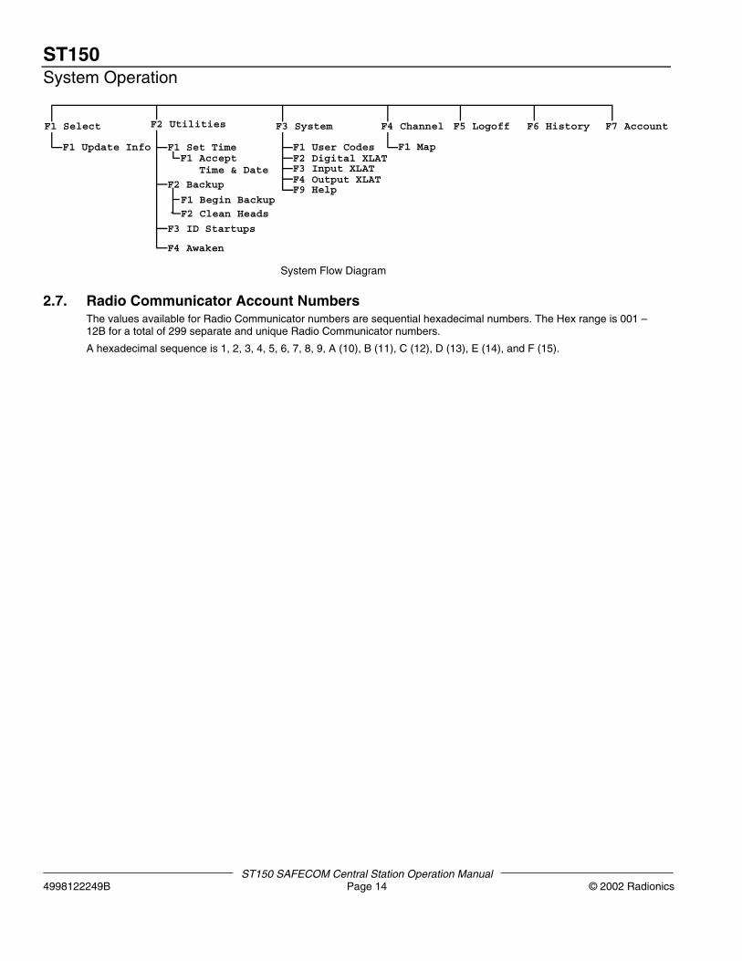
F1 Select F5 Logoff F6 History F7 Account
F1 Update Info F1 Set TimeF1 Accept Time & Date
F2 Backup
F1 Begin BackupF2 Clean Heads
F3 ID Startups
F4 Awaken
F2 Utilities
F1 User CodesF2 Digital XLATF3 Input XLATF4 Output XLATF9 Help
F4 Channel
F1 Map
F3 System
System Flow Diagram
2.7. Radio Communicator Account NumbersThe values available for Radio Communicator numbers are sequential hexadecimal numbers. The Hex range is 001 –12B for a total of 299 separate and unique Radio Communicator numbers.
A hexadecimal sequence is 1, 2, 3, 4, 5, 6, 7, 8, 9, A (10), B (11), C (12), D (13), E (14), and F (15).
SC9000
ST150 SAFECOM Central Station Operations Manual© 2002 Radionics Page 15 4998122249B
3. Installing and Communicating with RadioCommunicators
3.1. Selecting/Polling a Radio CommunicatorPress the F1=Remote option from the System Status Menu command window. The “Select a Remote” menu will bedisplayed.
After entering into the F1=SELECT function, any of the following methods may be used to specify the RadioCommunicator account number:
1. If you know the Radio Communicator number, type it in using the keyboard or numeric keypad.
2. Press the ↑ or ↓ keys to scan through all possible Radio Communicator numbers.
3. Press the “PgUp” or “PgDn” keys to scan through all the current Radio Communicator accounts in the SAFECOMSC9000 computer.
4. Press the “PgUp” or “PgDn” keys while holding down the CTRL key. This allows the operator to scan up or down toonly those Radio Communicator units that are offline.
5. After entering the desired Radio Communicator number, press the ENTER key.
If the number entered is already assigned to an active Radio Communicator, the screen will display the message “Pollingremote XXX depress ALT-X to fail. . .” in the upper right hand corner. This message will be displayed until anacknowledge (ACK) message is received from the Radio Communicator in the field. When the ACK is received, the“Remote Status” menu for the associated Radio Communicator will be displayed. There may be a slight delay in thedisplay of this menu, depending on the amount of message traffic activity on the RF Channel assigned to that RadioCommunicator.
If the number entered is new and is not assigned to an active Radio Communicator, the screen will display the message:"This remote does not exist.". This message simply means that the Radio Communicator number you selected is availableto be programmed as a new account. At this point, the operator may press F1 for the F1=Select option in the commandwindow. This allows for selection of a different Radio Communicator number. The operator may press F2 for theF2=Setup option in the command window to enter the Radio Communicator “Setup” menu. At this point, the operator mayassign this Radio Communicator number to a new account. See the applicable section for further discussion of theF1=SELECT option as per the Table of Contents.
3.2. Bringing a New SAFECOM Unit OnlineThese procedures are applicable for new or re-initialized Radio Communicators:
1. Ensure the correct CPU S/N, PID, Framer, and RF Channel for the Radio Communicator are entered on the RadioCommunicator Setup Menu #1 in the SAFECOM SC9000.
2. Apply power to the Radio Communicator. Remember to have an antenna connected.
Refer to the applicable SAFECOM Radio Communicator Installation Guide for a description of Safety Precautions,Pre-installation, Installation, and Initialization Procedures.
3. A new or initialized Radio Communicator will transmit a “startup XXXXXXXXX” record of events message to theSC9000 Receiver. (XXXXXXXXX is the CPU S/N.) If the SC9000 has an active account built for this RadioCommunicator and the SC9000 can hear this Radio Communicator, this message will be displayed next to the RadioCommunicator number that the operator has assigned to it. This message identifies the Radio Communicator asbeing New or Re-Initialized and directs the SAFECOM SC9000 to establish radio Communications with it anddownload or program the Radio Communicator with its associated Remote Setup Menu data. This message will alsoidentify the specific Radio Communicator and SAFECOM product type, it is communicating with, by the CPU S/N andPID. Each Radio Communicator has a unique CPU S/N assigned at the Radionics factory.
NOTE: If the SC9000 cannot locate a valid active Radio Communicator account associated with this CPU S/N, it willignore any Startup messages from that particular Radio Communicator.
4. The SC9000 will search through all the Radio Communicator accounts until it finds the account associated with theunit you have just started. After the SC9000 computer has matched an account with the new startup, the followingdownload sequence will occur automatically:
• The SC9000 assigns a Remote number (previously specified by the operator) to the Startup RadioCommunicator.
SC9000
ST150 SAFECOM Central Station Operation Manual4998122249B Page 16 © 2002 Radionics
• The SC9000 transmits a message to the Radio Communicator that contains the assigned RadioCommunicator number and Framer parameters to be programmed in the CPU of the Radio Communicator.
• When the Radio Communicator CPU is programmed with the Radio Communicator number and the Framerparameters, the Radio Communicator will perform a system reset and then send in a “restart” message tothe SC9000 computer.
• The SC9000 then downloads the remaining program parameters from the Radio Communicator account tothe Radio Communicator in the field.
• Once the download procedure is complete, the Radio Communicator transmits an ACK to the SC9000Receiver.
• This ACK message gives the SC9000 confirmation that the Radio Communicator download is complete andthe “program complete” message is displayed on the screen of the SC9000.
The Radio Communicator download is complete. The Radio Communicator is now on-line and operational for a radiocommunications link between the remote client location and the central station SAFECOM receiver.
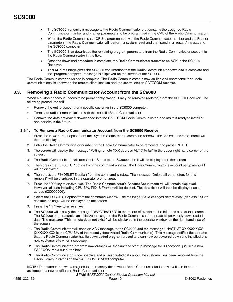
3.3. Removing a Radio Communicator Account from the SC9000When a customer account needs to be permanently closed, it may be removed (deleted) from the SC9000 Receiver. Thefollowing procedures will:
• Remove the entire account for a specific customer in the SC9000 computer.
• Terminate radio communications with this specific Radio Communicator.
• Remove the data previously downloaded into the SAFECOM Radio Communicator, and make it ready to install atanother site in the future.
3.3.1. To Remove a Radio Communicator Account from the SC9000 Receiver1. Press the F1=SELECT option from the “System Status Menu” command window. The “Select a Remote” menu will
then be displayed.
2. Enter the Radio Communicator number of the Radio Communicator to be removed, and press ENTER.
3. The screen will display the message “Polling remote XXX depress ALT-X to fail” in the upper right hand corner of thescreen.
4. The Radio Communicator will transmit its Status to the SC9000, and it will be displayed on the screen.
5. Then press the F2=SETUP option from the command window. The Radio Communicator’s account setup menu #1will be displayed.
6. Then press the F2=DELETE option from the command window. The message “Delete all parameters for thisremote?” will be displayed in the operator prompt area.
7. Press the “ Y “ key to answer yes. The Radio Communicator’s Account Setup menu #1 will remain displayed.However, all data including CPU S/N, PID, & Framer will be deleted. The data fields will then be displayed as allzeroes (000000000).
8. Select the ESC=EXIT option from the command window. The message “Save changes before exit? (depress ESC tocontinue editing)” will be displayed on the screen.
9. Press the “ Y “ key to answer yes.
10. The SC9000 will display the message “DEACTIVATED” in the record of events on the left hand side of the screen.The SC9000 then transmits an initialize message to the Radio Communicator to erase all previously downloadeddata. The message “This remote does not exist.” will be displayed in the operator window on the right hand side ofthe screen.
11. The Radio Communicator will send an ACK message to the SC9000 and the message “INACTIVE XXXXXXXXX”(XXXXXXXXX is the CPU S/N of the recently deactivated Radio Communicator). This message notifies the operatorthat the Radio Communicator has its downloaded program erased and can now be powered down and installed at anew customer site when necessary.
12. The Radio Communicator (program now erased) will transmit the startup message for 90 seconds, just like a newSAFECOM radio out of the box.
13. The Radio Communicator is now inactive and all associated data about the customer has been removed from theRadio Communicator and the SAFECOM SC9000 computer.
NOTE: The number that was assigned to the recently deactivated Radio Communicator is now available to be re-assigned to a new or different Radio Communicator.
SC9000
ST150 SAFECOM Central Station Operations Manual© 2002 Radionics Page 17 4998122249B
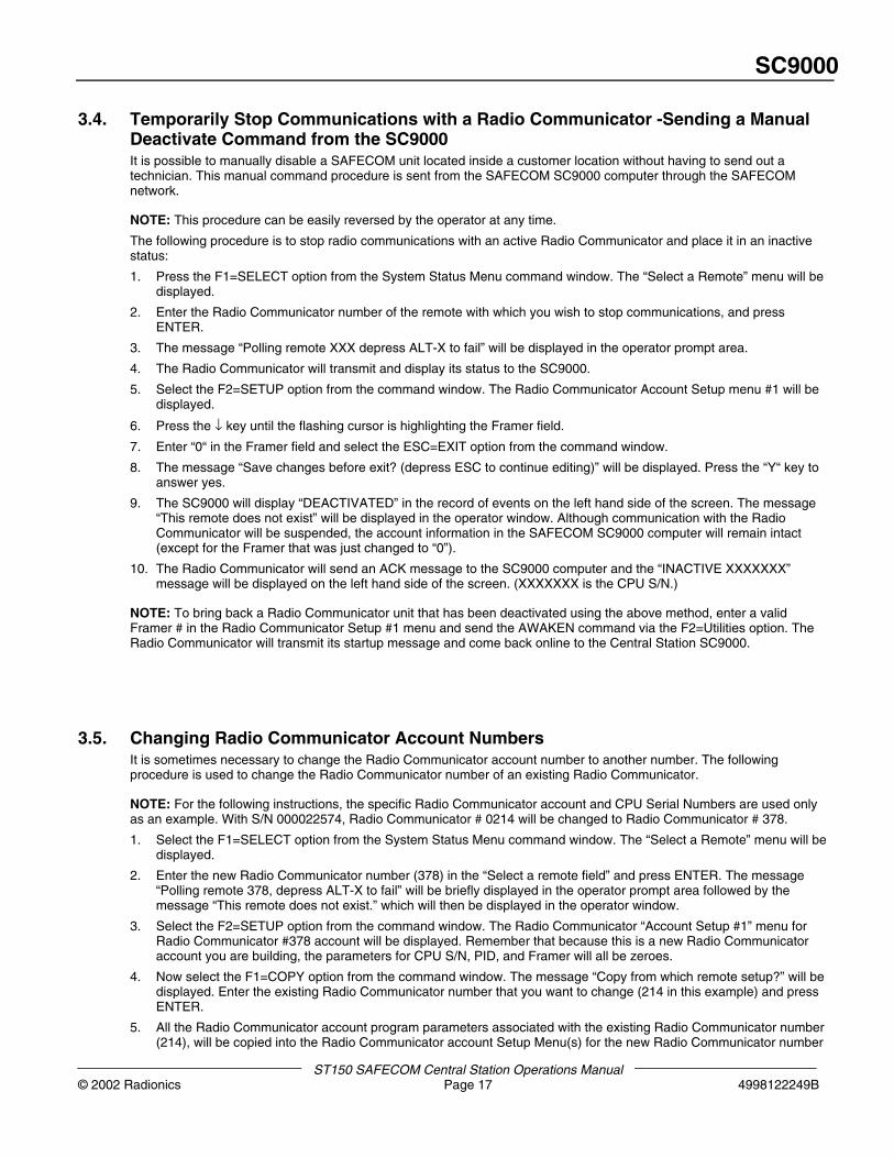
3.4. Temporarily Stop Communications with a Radio Communicator -Sending a ManualDeactivate Command from the SC9000It is possible to manually disable a SAFECOM unit located inside a customer location without having to send out atechnician. This manual command procedure is sent from the SAFECOM SC9000 computer through the SAFECOMnetwork.
NOTE: This procedure can be easily reversed by the operator at any time.
The following procedure is to stop radio communications with an active Radio Communicator and place it in an inactivestatus:
1. Press the F1=SELECT option from the System Status Menu command window. The “Select a Remote” menu will bedisplayed.
2. Enter the Radio Communicator number of the remote with which you wish to stop communications, and pressENTER.
3. The message “Polling remote XXX depress ALT-X to fail” will be displayed in the operator prompt area.
4. The Radio Communicator will transmit and display its status to the SC9000.
5. Select the F2=SETUP option from the command window. The Radio Communicator Account Setup menu #1 will bedisplayed.
6. Press the ↓ key until the flashing cursor is highlighting the Framer field.
7. Enter “0“ in the Framer field and select the ESC=EXIT option from the command window.
8. The message “Save changes before exit? (depress ESC to continue editing)” will be displayed. Press the “Y“ key toanswer yes.
9. The SC9000 will display “DEACTIVATED” in the record of events on the left hand side of the screen. The message“This remote does not exist” will be displayed in the operator window. Although communication with the RadioCommunicator will be suspended, the account information in the SAFECOM SC9000 computer will remain intact(except for the Framer that was just changed to “0”).
10. The Radio Communicator will send an ACK message to the SC9000 computer and the “INACTIVE XXXXXXX”message will be displayed on the left hand side of the screen. (XXXXXXX is the CPU S/N.)
NOTE: To bring back a Radio Communicator unit that has been deactivated using the above method, enter a validFramer # in the Radio Communicator Setup #1 menu and send the AWAKEN command via the F2=Utilities option. TheRadio Communicator will transmit its startup message and come back online to the Central Station SC9000.
3.5. Changing Radio Communicator Account NumbersIt is sometimes necessary to change the Radio Communicator account number to another number. The followingprocedure is used to change the Radio Communicator number of an existing Radio Communicator.
NOTE: For the following instructions, the specific Radio Communicator account and CPU Serial Numbers are used onlyas an example. With S/N 000022574, Radio Communicator # 0214 will be changed to Radio Communicator # 378.
1. Select the F1=SELECT option from the System Status Menu command window. The “Select a Remote” menu will bedisplayed.
2. Enter the new Radio Communicator number (378) in the “Select a remote field” and press ENTER. The message“Polling remote 378, depress ALT-X to fail” will be briefly displayed in the operator prompt area followed by themessage “This remote does not exist.” which will then be displayed in the operator window.
3. Select the F2=SETUP option from the command window. The Radio Communicator “Account Setup #1” menu forRadio Communicator #378 account will be displayed. Remember that because this is a new Radio Communicatoraccount you are building, the parameters for CPU S/N, PID, and Framer will all be zeroes.
4. Now select the F1=COPY option from the command window. The message “Copy from which remote setup?” will bedisplayed. Enter the existing Radio Communicator number that you want to change (214 in this example) and pressENTER.
5. All the Radio Communicator account program parameters associated with the existing Radio Communicator number(214), will be copied into the Radio Communicator account Setup Menu(s) for the new Radio Communicator number
SC9000
ST150 SAFECOM Central Station Operation Manual4998122249B Page 18 © 2002 Radionics
(378). There are now two identical Radio Communicator accounts except for the Radio Communicator numbers. Oneis Radio Communicator #214 (original), and the other is Radio Communicator #378 (new).
6. Press the ESC=EXIT option from the command window. The message “Save changes before exit? (depress ESC tocontinue editing)” will be displayed.
7. Press “ Y “ to answer yes. The message “Saving data . . .” will be displayed in the operator prompt window. TheSC9000 computer will then attempt to poll the Radio Communicator 378, but it will be unable to communicate with itbecause the Radio Communicator in the field is still programmed to respond only to calls for Radio Communicator214. Therefore, the message “This remote has failed to respond to a poll or message” for the new RadioCommunicator number 378, will be displayed in the operator window.
8. It is now necessary to deactivate the original Radio Communicator account (214). Press the F1=SELECT option fromthe command window. The message “Select a remote: 378” will be displayed. Enter the old Radio Communicatornumber (214), that will be deactivated and press ENTER. The Radio Communicator Status display for the old RadioCommunicator number (214) will be displayed.
9. Press the F2=SETUP option from the command window. The Radio Communicator Account Setup Menu #1 for theold Radio Communicator number, 214, will be displayed. Use the ↓ key to highlight the Framer parameter. Type “ 0 “in the Framer field and press the ESC=EXIT option from the command window. The message “Save changes beforeexit? (depress ESC to continue editing)” will be displayed.
10. Press “ Y “ to answer yes. The message “Saving data . . .” will be displayed in the operator prompt window, followedimmediately by the message “This remote does not exist” which will be displayed in the operator window for the oldRadio Communicator number, 214.
The following sequence of messages will be displayed in the record of events on the left hand side of the screen:
378 program complete 378 restart 378 startup 000022574 214 > INACTIVE 000022574 214 DEACTIVATED
11. It is now necessary to remove the old Radio Communicator account number from the SC9000 computer. Select theF1=SELECT option from the command window. The message “Select a remote: 214” will be displayed. PressENTER. The message “This remote does not exist” will be displayed.
12. Select the F2=SETUP option from the command window. The Radio Communicator Account Setup Menu #1 for theold Radio Communicator number, 214, will be displayed.
13. Select the F2=DELETE option from the command window. The message “Delete all parameters for this remote?” willbe displayed. Press “ Y “ to answer yes. The Radio Communicator Setup Menu #1 for the old Radio Communicatornumber, 214, will be set to all zeroes (000).
14. Select the ESC=Exit option from the command window. The message “Save changes before exit? (depress ESC tocontinue editing)” will be displayed. Press “ Y “ to answer yes. The message “Saving data . . .” will be displayed andfollowed by the message “This remote does not exist” for the old Radio Communicator number, 214.
The Radio Communicator account number 214 is now deleted from the SAFECOM SC9000 and can be used to set up anew account when desired.
SC9000
ST150 SAFECOM Central Station Operations Manual© 2002 Radionics Page 19 4998122249B
4. Radio Communicator Procedures
4.1. SC2104
4.1.1. SC2104 Alarm Panel Backup Communicators Overview
The SC2104 provides the ability to detect simultaneous loss of Telephone Line voltage and Line current to an alarm panelDialer. This Telephone Line Fault Monitoring (LINE CUT) capability is performed by connecting the SC2104 in seriesbetween an alarm panel Dialer and the telephone RJ31X or RJ32X phone jack. The Telephone Line Fault Monitoringensures immediate and accurate line status reporting and enhances system integrity.
The SC2104 is also capable of monitoring the status of eight (8) Inputs. These input lines allow End-Of-Line (EOL)supervisory loop status monitoring for NORMAL, OPEN, and SHORT contacts, alarm panel BELL OUTPUT, and pulldown to GROUND type conditions. Up to eight (8) Loops or Devices, two per SC2104 Input, may be monitored. Theseinputs may be driven from Normally Open or Normally Closed contacts, such as those found on a relay output, or may bedriven by a switching voltage source such as a programmable output or BELL OUT provided by many alarm panels.
The SC2104 is normally configured as a stand-alone device for interface with the customer's existing alarm panel. It islocated at a customer site; commercial or residential. The smaller physical dimensions of the SC2104 (4.5" W x 3.75" H x3.5" D) permit installation inside of an existing alarm panel. With the SC2104 placed inside the alarm panel enclosure,interconnect wiring will not be exposed, and the SC2104 will be in a protected environment, thus providing greater systemsecurity and integrity. The antenna can be mounted directly on the alarm panel via the Radionics factory provided RFcable, or remotely positioned with the Radionics factory provided “L” type bracket for optimum radio reception andtransmission.
The telephone line status reports and input status messages are digitally encoded by the SC2104 and sent via aSAFECOM network to the Central Station's SC9000 computer. The messages are processed by the SC9000 computerand sent to a Central Monitoring Station’s Automation Software for processing.
The SC2104 functions strictly in a supervisory capacity when interfaced with an existing alarm system. The SC2104 isdesigned for easy installation and interface with any Alarm system. Installation is performed by connecting the alarmpanel Dialer cable to the SC2104 modular “Dialer” connector, the House Phone cable to the SC2104 modular “ RJ31X”connector, and the alarm panel BELL OUT or PANIC/DURESS buttons directly to the SC2104 Inputs.
No modifications to the existing alarm system are required! The normal operation of the existing alarm panel and securitysystem is not affected in any way. The existing detectors and initiating circuits still report the status of items directly to thealarm panel. The SC2104 cannot send Input status messages via a Telephone Line. SAFECOM network radiocommunication is the only mode of Telephone Line Fault and SC2104 Input status reporting to the Central MonitoringStation.
4.1.2. Programming an SC2104 Account into the SC9000There are 2 Radio Communicator setup pages for all SC2104 accounts. The Radio Communicator account Setup Menusallow the operator to enter the programming parameters necessary to bring an SC2104 online. These Setup pages alsoallow the SC9000 operator to configure the SC2104 inputs and telephone line fault monitor.
All account parameters contained in the Radio Communicator account Setup Menus are transmitted via the SAFECOMnetwork to the SC2104 in the field. These parameters are downloaded into the SC2104 to establish the operatingcharacteristics for that SC2104.
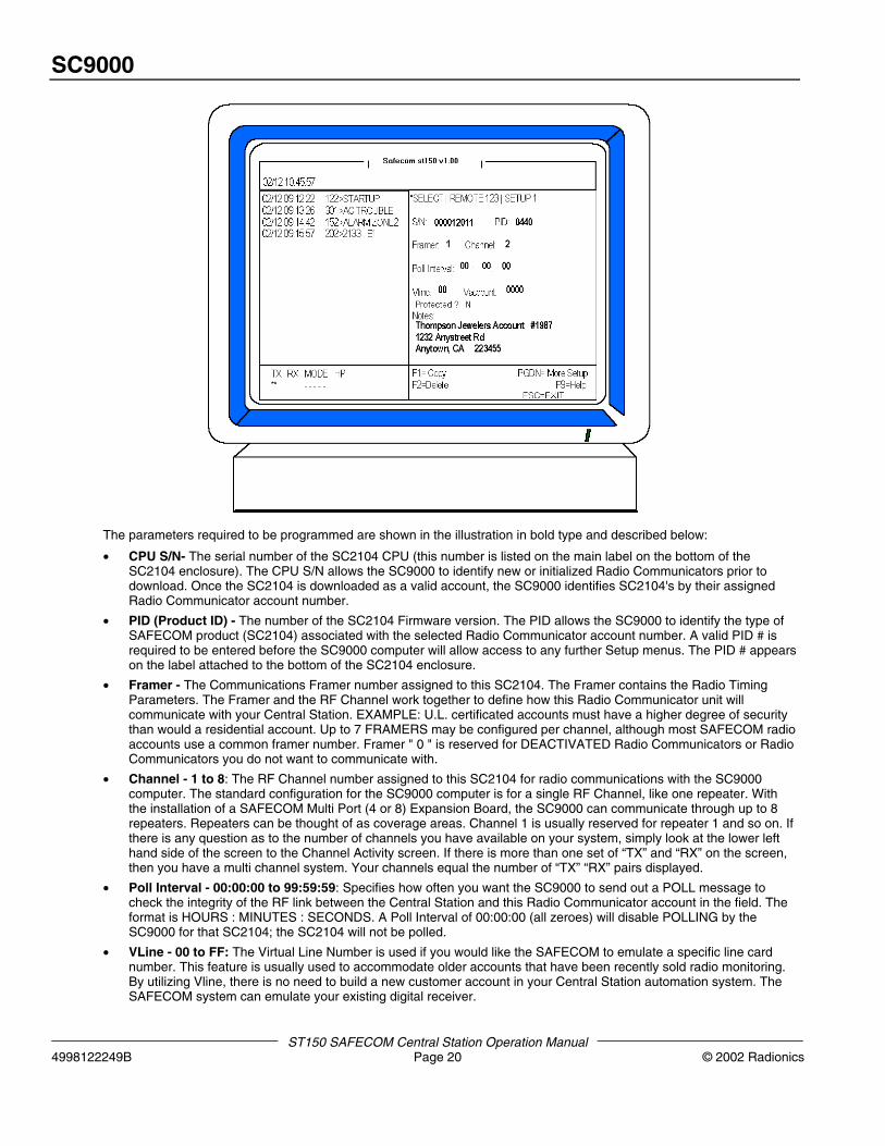
SC2104 Radio Communicator Account Setup Menu #1Refer to the following illustration of the Radio Communicator account Setup Menu #1:
SC9000
ST150 SAFECOM Central Station Operation Manual4998122249B Page 20 © 2002 Radionics
The parameters required to be programmed are shown in the illustration in bold type and described below:
• CPU S/N- The serial number of the SC2104 CPU (this number is listed on the main label on the bottom of theSC2104 enclosure). The CPU S/N allows the SC9000 to identify new or initialized Radio Communicators prior todownload. Once the SC2104 is downloaded as a valid account, the SC9000 identifies SC2104's by their assignedRadio Communicator account number.
• PID (Product ID) - The number of the SC2104 Firmware version. The PID allows the SC9000 to identify the type ofSAFECOM product (SC2104) associated with the selected Radio Communicator account number. A valid PID # isrequired to be entered before the SC9000 computer will allow access to any further Setup menus. The PID # appearson the label attached to the bottom of the SC2104 enclosure.
• Framer - The Communications Framer number assigned to this SC2104. The Framer contains the Radio TimingParameters. The Framer and the RF Channel work together to define how this Radio Communicator unit willcommunicate with your Central Station. EXAMPLE: U.L. certificated accounts must have a higher degree of securitythan would a residential account. Up to 7 FRAMERS may be configured per channel, although most SAFECOM radioaccounts use a common framer number. Framer " 0 " is reserved for DEACTIVATED Radio Communicators or RadioCommunicators you do not want to communicate with.
• Channel - 1 to 8: The RF Channel number assigned to this SC2104 for radio communications with the SC9000computer. The standard configuration for the SC9000 computer is for a single RF Channel, like one repeater. Withthe installation of a SAFECOM Multi Port (4 or 8) Expansion Board, the SC9000 can communicate through up to 8repeaters. Repeaters can be thought of as coverage areas. Channel 1 is usually reserved for repeater 1 and so on. Ifthere is any question as to the number of channels you have available on your system, simply look at the lower lefthand side of the screen to the Channel Activity screen. If there is more than one set of “TX” and “RX” on the screen,then you have a multi channel system. Your channels equal the number of “TX” “RX” pairs displayed.
• Poll Interval - 00:00:00 to 99:59:59: Specifies how often you want the SC9000 to send out a POLL message tocheck the integrity of the RF link between the Central Station and this Radio Communicator account in the field. Theformat is HOURS : MINUTES : SECONDS. A Poll Interval of 00:00:00 (all zeroes) will disable POLLING by theSC9000 for that SC2104; the SC2104 will not be polled.
• VLine - 00 to FF: The Virtual Line Number is used if you would like the SAFECOM to emulate a specific line cardnumber. This feature is usually used to accommodate older accounts that have been recently sold radio monitoring.By utilizing Vline, there is no need to build a new customer account in your Central Station automation system. TheSAFECOM system can emulate your existing digital receiver.
SC9000
ST150 SAFECOM Central Station Operations Manual© 2002 Radionics Page 21 4998122249B
• VAccount - 0001 to FFFF: The Virtual Account Number is used to specify the Subscriber Account number forreporting SC2104 messages to the Automation software. The Virtual Account Number allows the SC2104 to appearas any Subscriber Account in the Automation software. This feature is usually used to accommodate older accountsthat have been recently sold radio monitoring. By utilizing VAccount, there is no need to build a new customeraccount in you Central Station automation system. The SAFECOM system can emulate your existing digital receiver.If the Virtual Account is set to 0000, the SC2104 messages will be reported to the Automation software using theSAFECOM Radio Communicator number.
• Vline and VAccount apply to a full ST1000 system using an external automation software package. They are notutilized in the ST150 software system.
• Notes: The Notes area is used to enter four (4) lines, 35 characters each line, of plain language text. The Notes areais usually used to identify important customer information such as name, address, phone number, etc.
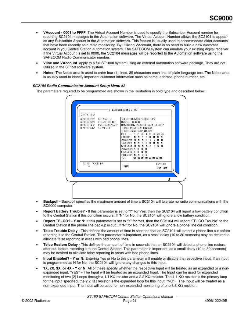
SC2104 Radio Communicator Account Setup Menu #2The parameters required to be programmed are shown in the illustration in bold type and described below:
• Backpoll - Backpoll specifies the maximum amount of time a SC2104 will tolerate no radio communications with theSC9000 computer.
• Report Battery Trouble? - If this parameter is set to “Y” for Yes, then the SC2104 will report a low battery conditionto the Central Station if this condition occurs. If “N” for No, the SC2104 will ignore a low battery condition.
• Report TELCO? - Y or N: If this parameter is set to “Y” for Yes, then the SC2104 will report “TELCO Trouble” to theCentral Station if the phone line backup is cut.. If “N” for No, the SC2104 will ignore a phone line cut condition.
• Telco Trouble Delay - This defines the amount of time in seconds that an SC2104 will detect a phone line cut beforereporting it to the Central Station. This parameter is important, as a small delay (10 to 30 seconds) may be desired toalleviate false reporting in areas with bad phone lines.
• Telco Restore Delay - This defines the amount of time in seconds that an SC2104 will detect a phone line restore,after cut, before reporting it to the Central Station. This parameter is important, as a small delay (10 to 30 seconds)may be desired to alleviate false reporting in areas with bad phone lines.
• Input Enabled? - Y or N: Entering Yes or No to this parameter will enable or disable the respective input. If an inputis programmed as N for No, the SC2104 will ignore any changes to this input.
• 1X, 2X, 3X, or 4X - Y or N: All of these specify whether the respective Input will be treated as an expanded or a non-expanded input. “YES” = The Input will be treated as an expanded Input. The Input can be used for expandedmonitoring of two (2) Loops through a 1.1 KΩ resistor and a 2.2 KΩ resistor. The 1.1 KΩ resistor is the primary loopfor the input specified, the 2.2 KΩ resistor is the expanded loop for this input. “NO” = The Input will be treated as anon-expanded Input. The Input will be used for non-expanded monitoring of one 3.3 KΩ resistor.
SC9000
ST150 SAFECOM Central Station Operation Manual4998122249B Page 22 © 2002 Radionics
• Delay Short - Y or N: This parameter will program in a delay in the respective input that will retard the reporting ofthe input when tripped.
• Fault Short - Y or N: Fault Short specifies whether the status of the Input will be treated as a fault when a Shortcondition is detected across the EOL resistor on the specified Input . When the input is configured for expanded, thePrimary and Expanded Loops will be individually monitored and a separate message will be reported when a Shortcondition is detected. “YES” = A Priority Alert message will blink and an audible tone will sound on the SC9000computer.
• Mask Short- Y or N: Mask short allows the operator to command any or all inputs monitored by the SC2104 to onlyreport input trips if the phone line is cut. As long as the phone line is good, the SC2104 will ignore any trips on aMASKED input.
• Delay Open - Y or N: This parameter will program in a delay in the respective input that will retard the reporting ofthe input when tripped.
• Fault Open- Y or N: Fault Open specifies whether the status of the Input will be treated as a fault when an Opencondition is detected on the specified Input .When the Input is configured for expanded, the Input will be treated as afault if an Open is detected on either the primary or the expanded loop. “YES” = A Priority Alert message will blinkand an audible tone will sound on the SC900 computer.
• Mask Open- Y or N: Mask open allows the operator to command any or all inputs monitored by the SC2104 to onlyreport input trips if the phone line is cut. As long as the phone line is good, the SC2104 will ignore any trips on amasked input.
• Input XLAT - 00 to 4F: The Input Translation Table (XLAT) specifies the English plain text definition that you wish toassign to an INPUT. The text will be displayed in place of the default messages “Open, Short, or Normal”. The InputTranslation Table has 5 pages, with 16 line numbers per page, for a total of 80 line numbers. Each line provides amaximum of 8 characters of English text translation for Normal, Open, and Short Input conditions. The correspondingtext assigned to the respective Input in the translation table is only for display at the SC9000 computer. It is not partof the message sent to the Automation software. Input translation gives the operator the ability to allow an input on anSC2104 to report “TEMP HI” or “TEMP LO” instead of “INPUT SHORT” or “INPUT OPEN”. This ability can be veryuseful for processing alarm messages in the unlikely event of an automation system failure. Each translation table(XLAT) line contains three available conditions that the operator must define, “SHORT, OPEN, & NORMAL”. Theseare the only conditions the SC2104 can detect and report on it’s inputs.
NOTE: The SAFECOM ST150 v1.00 and higher software default values for all new Radio Communicator inputtranslation tables are “ 00 “ and the default values for line #00, in the Input Translation Table, are NORMAL, OPEN, andSHORT.
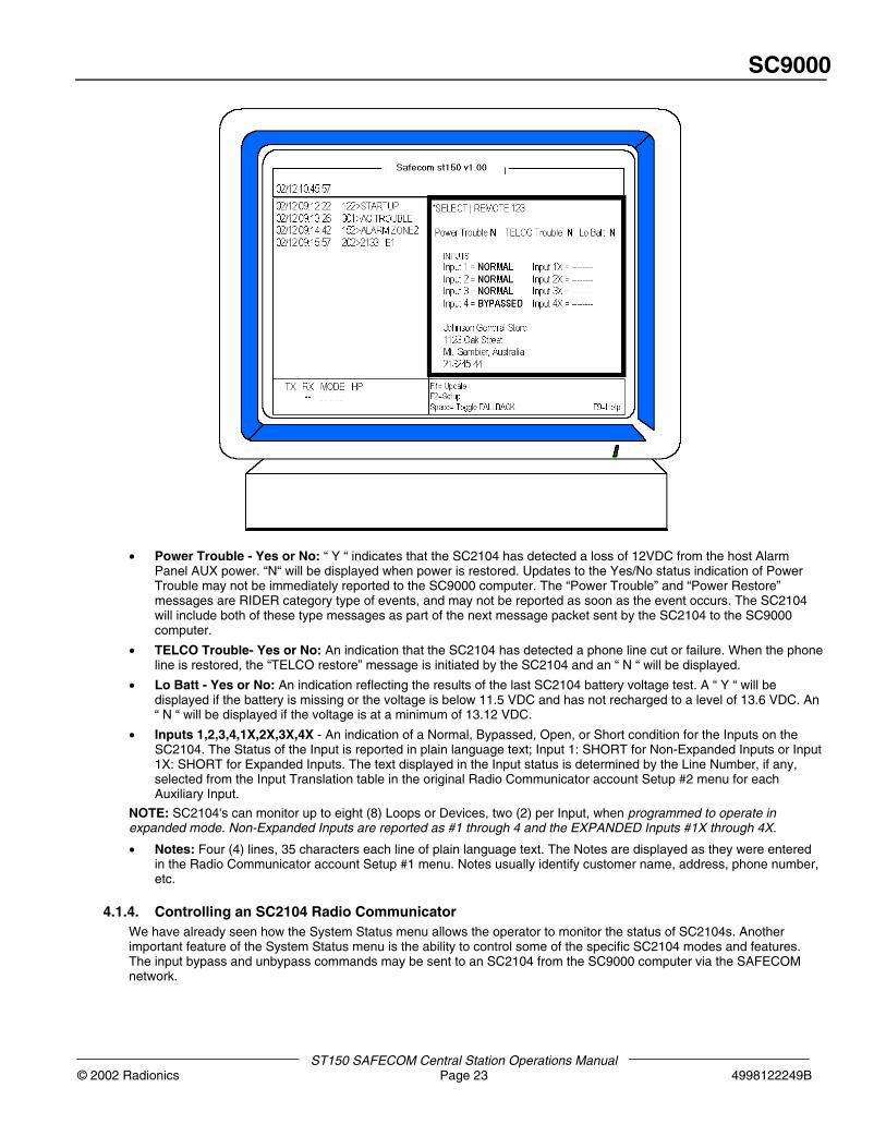
4.1.3. Remote Status Display – the SC2104 Radio Communicator’s Response to a Manual “Poll” by theOperator
If the Central Station operator performs a manual poll of a Radio Communicator, the remote status display comes up onthe screen to show the operator the exact status of the Radio Communicator in the field. The Remote Status displayallows the operator to individually control and monitor the status of an SC2104. The following is a description of thoseitems available for viewing and control on the Remote Status display (See the diagram below and the followingexplanation):
SC9000
ST150 SAFECOM Central Station Operations Manual© 2002 Radionics Page 23 4998122249B
• Power Trouble - Yes or No: “ Y “ indicates that the SC2104 has detected a loss of 12VDC from the host AlarmPanel AUX power. “N“ will be displayed when power is restored. Updates to the Yes/No status indication of PowerTrouble may not be immediately reported to the SC9000 computer. The “Power Trouble” and “Power Restore”messages are RIDER category type of events, and may not be reported as soon as the event occurs. The SC2104will include both of these type messages as part of the next message packet sent by the SC2104 to the SC9000computer.
• TELCO Trouble- Yes or No: An indication that the SC2104 has detected a phone line cut or failure. When the phoneline is restored, the “TELCO restore” message is initiated by the SC2104 and an “ N “ will be displayed.
• Lo Batt - Yes or No: An indication reflecting the results of the last SC2104 battery voltage test. A “ Y “ will bedisplayed if the battery is missing or the voltage is below 11.5 VDC and has not recharged to a level of 13.6 VDC. An“ N “ will be displayed if the voltage is at a minimum of 13.12 VDC.
• Inputs 1,2,3,4,1X,2X,3X,4X - An indication of a Normal, Bypassed, Open, or Short condition for the Inputs on theSC2104. The Status of the Input is reported in plain language text; Input 1: SHORT for Non-Expanded Inputs or Input1X: SHORT for Expanded Inputs. The text displayed in the Input status is determined by the Line Number, if any,selected from the Input Translation table in the original Radio Communicator account Setup #2 menu for eachAuxiliary Input.
NOTE: SC2104's can monitor up to eight (8) Loops or Devices, two (2) per Input, when programmed to operate inexpanded mode. Non-Expanded Inputs are reported as #1 through 4 and the EXPANDED Inputs #1X through 4X.
• Notes: Four (4) lines, 35 characters each line of plain language text. The Notes are displayed as they were enteredin the Radio Communicator account Setup #1 menu. Notes usually identify customer name, address, phone number,etc.
4.1.4. Controlling an SC2104 Radio CommunicatorWe have already seen how the System Status menu allows the operator to monitor the status of SC2104s. Anotherimportant feature of the System Status menu is the ability to control some of the specific SC2104 modes and features.The input bypass and unbypass commands may be sent to an SC2104 from the SC9000 computer via the SAFECOMnetwork.
SC9000
ST150 SAFECOM Central Station Operation Manual4998122249B Page 24 © 2002 Radionics
Bypassing SC2104 Inputs from the SC9000The SC9000 provides the operator with the option of sending a command to an SC2104 instructing it to BYPASSreporting any changes to a specific input. This function may be necessary when a faulty detector has been identified, or ifthe SC2104 is currently being serviced and the signals that would normally be sent are not desired. Some Central Stationoperators refer to this mode as “TEST MODE” indicating that the SC2104 will not send any input messages to theSC9000 when tripped.
To Send a Manual Input Bypass Command1. Press the F1=SELECT option from the System Status Menu Command Window. The Select a Remote menu will be
displayed. Enter the Radio Communicator number in the “Select a remote:” field and press ENTER.
2. The operator message “Polling remote XXX depress ALT-X to fail. . .” is displayed until an acknowledge (ACK)message is received from the SC2104; then the Remote Status screen will be displayed allowing the operator to viewthe status of the SC2104.
3. Using the “↓↑” keys position the cursor on the desired input to bypass field. That input to be bypassed field will behighlighted light blue to indicate a modification may be made by the operator. Then press the SPACE bar once. Theoperator prompt “Transmitting to remote XXX, depress ALT-X to fail ...” is displayed until an ACK is received from theSC2104.
4. The SC2104 will bypass the input selected and send the “Input X BYPASSED” message to the SC9000 computer.This input is now bypassed and will not report any input trips on this specific input.
NOTE: In the event of a SC2104 Restart (complete AC and BATTERY removal), all of the Inputs will return to normalreporting of status changes.
To Send a Manual Input Un-Bypass Command (Reverse a Bypass Command)1. Press the F1=SELECT option from the System Status Menu Command Window. The Select a Remote menu will be
displayed. Enter the Radio Communicator number in the “Select a remote:” field and press ENTER.
2. The operator message “Polling remote XXX depress ALT-X to fail. . .” is displayed until an acknowledge (ACK)message is received from the SC2104; then the Remote Status screen will be displayed allowing the operator to viewthe status of the SC2104.
3. Using the “↓↑” keys position the cursor on the desired input to unbypass. That input to be unbypassed will behighlighted light blue to indicate a modification may be made by the operator. Then press the SPACE bar once. Theoperator prompt “Transmitting to remote XXX, depress ALT-X to fail ...” is displayed until an ACK is received from theSC2104. The SC2104 will then unbypass the input selected and send the “Input X unbypassed” message to theSC9000 computer. The reporting of status changes to that input has now been restored to normal input reporting orunbypassed reporting.
4.2 SC8016
4.2.1 SC8016 Full Data Transfer Communicator Overview
The SC8016 Radio Communicator is located at a customer site; commercial or residential. The SC8016 is a high securitycontrol dialer based on the Solution-16 platform, which uses supervised bi-directional radio signaling to communicate withthe control room using Contact ID format.
SC9000
ST150 SAFECOM Central Station Operations Manual© 2002 Radionics Page 25 4998122249B
4.2.2 Programming an SC8016 Account into the SC9000There are two Radio Communicator setup pages for all SC8016 accounts. The Remote Setup Menus allow the operatorto enter the programming parameters necessary to bring an SC8016 online. All account parameters contained in theRemote Setup Menus are transmitted via the SAFECOM network to the SC8016 in the field. These parameters aredownloaded into the SC8016 to establish the operating characteristics for that SC8016.
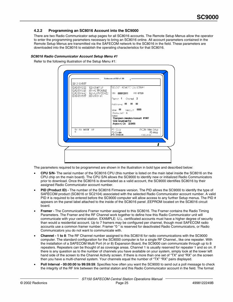
SC8016 Radio Communicator Account Setup Menu #1Refer to the following illustration of the Setup Menu #1:
The parameters required to be programmed are shown in the illustration in bold type and described below:
• CPU S/N- The serial number of the SC8016 CPU (this number is listed on the main label inside the SC8016 on theCPU chip on the main board). The CPU S/N allows the SC9000 to identify new or initialized Radio Communicatorsprior to download. Once the SC8016 is downloaded as a valid account, the SC9000 identifies SC8016 by theirassigned Radio Communicator account number.
• PID (Product ID) - The number of the SC8016 Firmware version. The PID allows the SC9000 to identify the type ofSAFECOM product (SC8016 or SC2104) associated with the selected Radio Communicator account number. A validPID # is required to be entered before the SC9000 computer will allow access to any further Setup menus. The PID #appears on the panel label attached to the inside of the SC8016 panel ,EEPROM located on the SC8016 circuitboard.
• Framer - The Communications Framer number assigned to this SC8016. The Framer contains the Radio TimingParameters. The Framer and the RF Channel work together to define how this Radio Communicator unit willcommunicate with your central station. EXAMPLE: U.L. certificated accounts must have a higher degree of securitythan would a residential account. Up to 7 framers may be configured per channel, though most SAFECOM radioaccounts use a common framer number. Framer "0 " is reserved for deactivated Radio Communicators, or RadioCommunicators you do not want to communicate with.
• Channel - 1 to 8: The RF Channel number assigned to this SC8016 for radio communications with the SC9000computer. The standard configuration for the SC9000 computer is for a single RF Channel., like one repeater. Withthe installation of a SAFECOM Multi Port (4 or 8) Expansion Board, the SC9000 can communicate through up to 8repeaters. Repeaters can be thought of as coverage areas. Channel 1 is usually reserved for repeater 1 and so on. Ifthere is any question as to the number of channels you have available on your system, simply look at the lower lefthand side of the screen to the Channel Activity screen. If there is more than one set of “TX” and “RX” on the screenthen you have a multi-channel system. Your channels equal the number of “TX” “RX” pairs displayed.
• Poll Interval - 00:00:00 to 99:59:59: Specifies how often you want the SC9000 to send out a poll message to checkthe integrity of the RF link between the central station and this Radio Communicator account in the field. The format
SC9000
ST150 SAFECOM Central Station Operation Manual4998122249B Page 26 © 2002 Radionics
is HOURS : MINUTES : SECONDS. A Poll Interval of 00:00:00 (all zeroes) will disable POLLING by the SC9000 forthat SC8016. The SC8016 will not be polled.
• VLine - 00 to FF: The Virtual Line Number is used if you would like the SAFECOM Receiver to emulate a specificline card number. This feature is usually used to accommodate older accounts that have been recently sold radiomonitoring. By utilizing Vline, there is no need to build a new customer account in your central station automationsystem. The SAFECOM system can emulate your existing digital receiver.
• VAccount - 0001 to FFFF: The Virtual Account Number is used to specify the Subscriber Account number forreporting SC8016 and Alarm Panel Dialer messages to the Automation software. The Virtual Account Number allowsthe SC8016 and/or Alarm Panel to appear as any Subscriber Account in the Automation software. This feature isusually used to accommodate older accounts that have been recently sold radio monitoring. By utilizing VAccount,there is no need to build a new customer account in your central station automation system. The SAFECOM systemcan emulate your existing digital receiver. If the Virtual Account is set to 0000, the SC8016 message will be reportedto the Automation software using the SAFECOM Radio Communicator number.
• Vline and VAccount apply to a full ST1000 system using an external automation software package. They are notutilized in the ST150 software system.
• Notes: The Notes area is used to enter four (4) lines of plain language text, up to 35 characters per line. The Notesarea is usually used to identify important customer information such as name, address, phone number, etc.
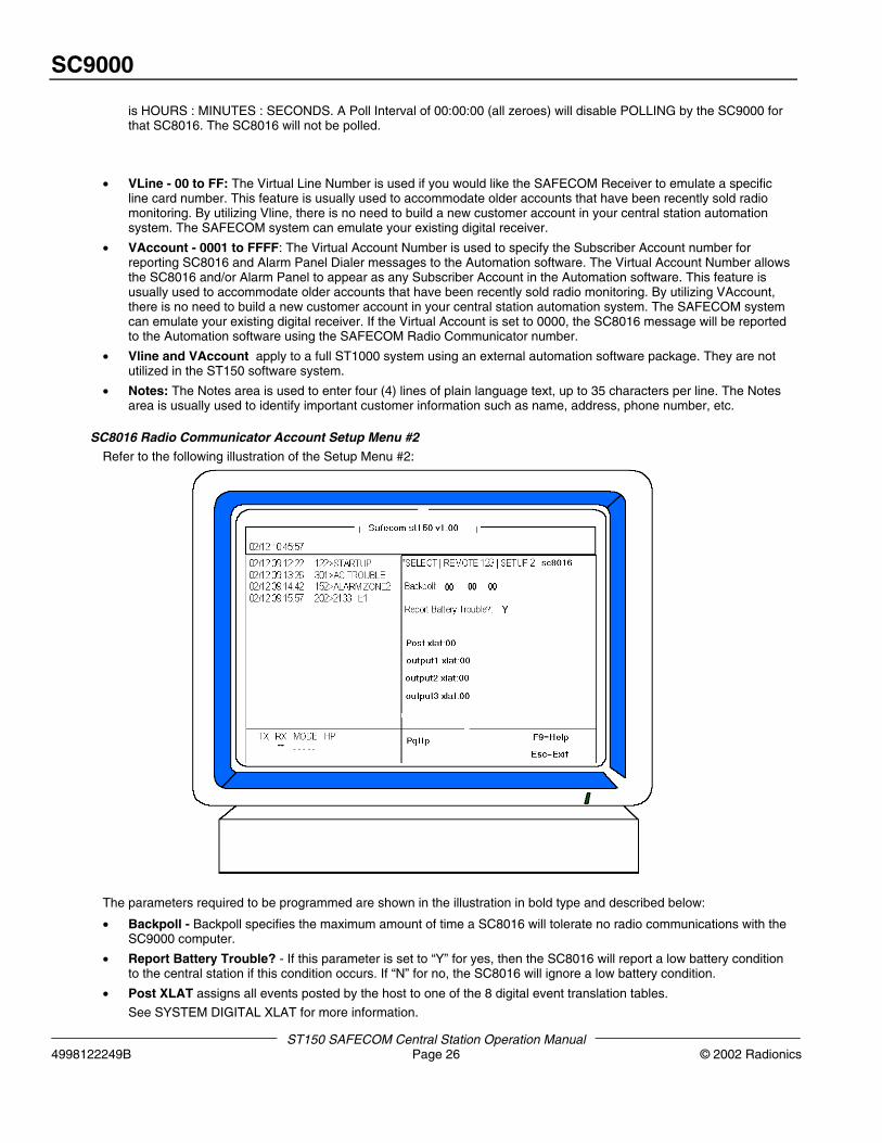
SC8016 Radio Communicator Account Setup Menu #2Refer to the following illustration of the Setup Menu #2:
The parameters required to be programmed are shown in the illustration in bold type and described below:
• Backpoll - Backpoll specifies the maximum amount of time a SC8016 will tolerate no radio communications with theSC9000 computer.
• Report Battery Trouble? - If this parameter is set to “Y” for yes, then the SC8016 will report a low battery conditionto the central station if this condition occurs. If “N” for no, the SC8016 will ignore a low battery condition.
• Post XLAT assigns all events posted by the host to one of the 8 digital event translation tables.
See SYSTEM DIGITAL XLAT for more information.
SC9000
ST150 SAFECOM Central Station Operations Manual© 2002 Radionics Page 27 4998122249B
• Panel Arm XLAT assigns the Panel Arm output to one of the 80 output translation lines.
• Output1 XLAT assigns the specified control to one of the 80 output translation lines.
NOTE: See SYSTEM OUTPUT for more information.
• Output XLAT - 00 to 4F: The Output Translation Table (XLAT) specifies the English plain text definition that you wishto assign to an OUTPUT. The text will be displayed in place of the default messages “Enabled” or “Disabled”. TheOutput Translation Table has 5 pages, with 16 line numbers per page, for a total of 80 line numbers. Each lineprovides a maximum of 8 characters for English text translation for Enable and Disabled Output conditions. Thecorresponding text assigned to the respective Output in the translation table is only for display at the SC9000computer. It is not part of the message sent to the Automation software. Output translation gives the operator theability to allow an Output on SC8016 to report “PUMP ON” or “PUMP OFF” instead of “OUTPUT ENABLED” or“OUTPUT DISABLED”. This ability can be very useful for remote control applications. Each translation table (XLAT)line contains two available conditions that the operator must define, “ENABLED” & “DISABLED”.. These are the onlyconditions an SC8016 output can be in and report.
NOTE: The SAFECOM ST150 v1.00 and higher software default values for all new Radio Communicator outputs are “ 00“ and the default values for line #00 in the Output Translation Table are enabled and disabled.
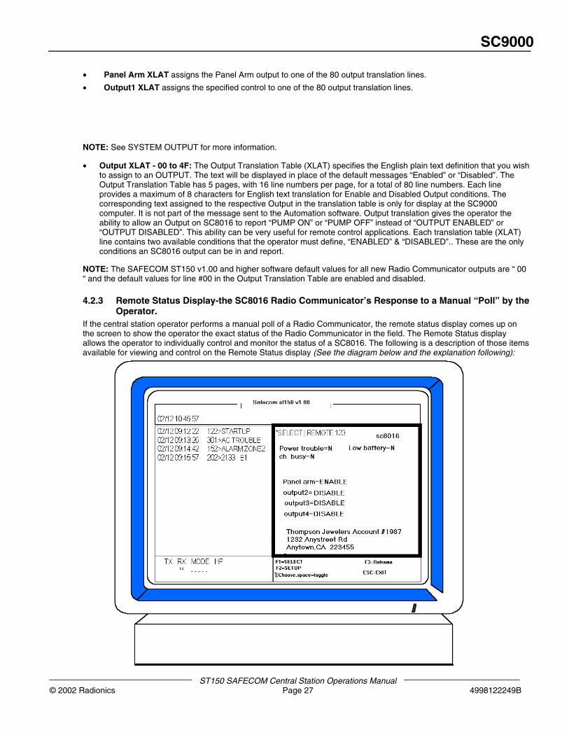
4.2.3 Remote Status Display-the SC8016 Radio Communicator’s Response to a Manual “Poll” by theOperator.
If the central station operator performs a manual poll of a Radio Communicator, the remote status display comes up onthe screen to show the operator the exact status of the Radio Communicator in the field. The Remote Status displayallows the operator to individually control and monitor the status of a SC8016. The following is a description of those itemsavailable for viewing and control on the Remote Status display (See the diagram below and the explanation following):
SC9000
ST150 SAFECOM Central Station Operation Manual4998122249B Page 28 © 2002 Radionics
• Power Trouble ( Yes or No ) : “ Y “ indicates that the SC8016 has detected a loss of AC power. Updates to theYes/No status indication of Power Trouble may not be immediately reported to the SC9000 computer. The “PowerTrouble” and “Power Restore” messages are RIDER category type of events, and may not be reported as soon asthe event occurs. The SC8016 will include both of these type messages as part of the next message packet sent bythe SC8016 to the SC9000 computer.
• Low Battery ( Yes or No ) : An indication reflecting the results of the last SC8016 battery voltage test. A dynamicbattery test is preformed every time the panel is armed and then every four hours afterwards.
• Ch. Busy ( Yes or No ) : If Report CHANNEL BUSY/CLEAR is (y)yes, then system and remote channel busy andchannel clear reports will be send to the automation system. Otherwise, system reports will be send as RFtroubles/restores on 0000, and remote reports will not be reported.
• Panel Arm : Enabled or Disabled. Current Panel arming status is displayed. This state can be toggled by the centralstation by highlighting the field and hitting the space bar
• Outputs,2,3,4: An indication of the Disabled or Enabled status of the (3) SC8016 Outputs. The Status each Output isreported in plain language text; Output2: DISABLED. The text displayed, in the Output status is determined by theLine Number selected, if any, from the Output Translation table on the Radio Communicator account Setup #2 menufor each Output. If “- - - - - - - -” is displayed in the Output status field instead of text, the Output Type has beenprogrammed to a type other than “ 0 ” on the Radio Communicator account Setup menu #2. Any output type besides“0” means the output status is controlled by the SC8016 in the field.
• Notes: Four (4) lines, 35 characters each line of plain language text: The Notes are displayed as they were enteredin the Radio Communicator account Setup #1 menu. Notes usually identify customer name, address, phone number,etc.
.
Controlling the SC8016’s OutputSafecom can remotely operate up to 3 outputs on the SC8016 as well as Arm and Disarm from the ST150 software. TheSC8016 needs to be programmed for this function to work. See the SC8016/Solution-16 Safecom Installation Manual forfurther details.
To Send a Manual Output Enable Command to an SC8016 from the SC90001. Press the F1=SELECT option from the System Status Menu Command Window. The Select a Remote menu will be
displayed. Enter the Radio Communicator number in the “Select a remote:” field and press ENTER.
2. The operator message “Polling remote XXX depress ALT-X to fail. . .” is displayed until an acknowledge (ACK)message is received from the SC8016; then the Remote Status screen will be displayed allowing the operator to viewthe status of the SC8016.
3. Using the “↓↑” keys position the cursor on the desired output to enable. That output to be enabled will be highlightedlight blue to indicate a modification may be made by the operator. Then press the SPACE bar once. The operatorprompt “Transmitting to remote XXX, depress ALT-X to fail ...” is displayed until an ACK is received from the SC8016.The SC8016 will then enable the input selected and send the “Input X ENABLED” message to the SC9000 computer.The input is now enabled and is controlling whatever devices (air conditioners, pumps, tank valves, sirens, lights,CCTV cameras, access control devices, and arm/disarm Alarm Panels) it is connected to. The English text displayed(ENABLED) in the Output status is determined by the Line Number selected from the Output Translation table (XLAT)on the Radio Communicator account Setup Menu #2 for each Auxiliary Output. Some Central Station operators preferto use the output translation table (XLAT) to allow the output relay to report “PUMP ON” or “DISARMED” instead ofthe default “ENABLED” or “DISABLED”
NOTE: In the event of a SC8016 Restart (loss of both AC and Battery backup), all of the Output Relays will return to theDISABLED condition. This condition will then be reported to the Central Station directly following the RESTART message.
SC9000
ST150 SAFECOM Central Station Operations Manual© 2002 Radionics Page 29 4998122249B
To Send a Manual Output Disable Command to an SC8016 from the SC90001. Press the F1=SELECT option from the System Status Menu Command Window. The Select a Remote menu will be
displayed. Enter the Radio Communicator number in the “Select a remote:” field and press ENTER.
2. The operator message “Polling remote XXX depress ALT-X to fail. . .” is displayed until an acknowledge (ACK)message is received from the SC8016; then the Remote Status screen will be displayed, allowing the operator toview the status of the SC8016.
3. Using the “↓↑” keys position the cursor on the desired output to disable. That output to be disabled will be highlightedlight blue to indicate a modification may be made by the operator. Then press the SPACE bar once. The operatorprompt “Transmitting to remote XXX, depress ALT-X to fail ...” is displayed until an ACK is received from the SC8016.The SC8016 will then disable the input selected and send the “Input X DISABLED” message to the SC9000computer. The input is now disabled and is controlling whatever devices (air conditioners, pumps, tank valves, sirens,lights, CCTV cameras, access control devices, and arm/disarm Alarm Panels) it is connected to. The English textdisplayed (DISABLED), in the Output status, is determined by the Line Number selected from the Output Translationtable (XLAT) on the Radio Communicator account Setup Menu #2 for each Auxiliary Output. Some Central Stationoperators prefer to use the output translation table (XLAT) to allow the output relay to report “PUMP OFF” or“ARMED” instead of the default “ENABLED” or “DISABLED”.
5. System Commands
5.1. Using the F2=Utilities System FunctionsThe F2=Utilities option in the SC9000 computer allows the operator to perform various system functions that can be veryuseful. The following function options are available from the F2=Utilities menu:
• F1=Set system date and time.
• F2=Make a backup copy of all system and Remote Setup parameter data.
• F3=Display all unknown startup (unprogrammed) Radio Communicators - ID STARTUPS.
• F4=Transmit an AWAKEN command to all startup (unprogrammed) Radio Communicators.
The operator prompt "Data files require backup!" will be displayed while the F2=Utilities menus are selected if a systemBackup is required. This prompt is a reminder that modifications and/or additions have been made to the Data Files sincethe last backup was performed.
5.1.1. F1=Set System Time and Date1. Press the F2=Utilities option from the System Status Menu command window.
2. Press the F1=Set time option from the command window. The Set Time Menu will be displayed and the cursor will bepositioned in the first digit field. The format for system time is Hours:Minutes:Seconds. Enter the Hour and pressENTER.
3. Then enter the Minutes and press ENTER. Then enter the Seconds and press ENTER. The cursor will then advanceto the first digit of the Month field. The format for the display of system date is Month/Day/Year.
NOTE: The system date will be displayed in a Day/Month/Year format if “ Y “ is selected for the International Datefield on the Automation Menu via the F3=System option. However, for entering the date, via the F1=Set time option,the format is Month/Day/Year.
4. Enter the number of the Month and press ENTER. Then enter the Day of the month and press ENTER. Finally, enterthe Year and press ENTER. Press F1 when done. The system time and date will be updated and the followingoccurs:
• The display time and date readouts in the System Date & Time window will reflect your update.
• The record or events message “<- Old date/time” will be initiated to provide a record of the system date andtime prior to the update.
• The record or events message “<- New date/time” will be initiated to provide a record of the new systemdate and time that was entered for the update.
SC9000
ST150 SAFECOM Central Station Operation Manual4998122249B Page 30 © 2002 Radionics
SC9000 Year 2000 Compliance
The Compaq 386 PC that ships as part of the SC9000 UL Listed Central Station system contains a non-compliant Year2000 BIOS. After the Year 2000 rollover occurs, the PC’s time and date MUST be manually reset at least once, even ifthe date appears to be correct. If power is not applied during the Year 2000 rollover, the system clock resets to January4, 1980. This can be manually reset to the Year 2000 for continued normal operation by performing one of the followingprocedures:
To set the clock from DOSStart at the DOS C:> Prompt
1. To get to DOS, press <ESC> key during SAFECOM® boot -up.
2. At the DOS prompt, type DATE <Return>.
3. This will bring up the current date display and a prompt that says “Enter new date (mm-dd-yy) “.
4. Enter the new date Note: Dates must be entered in a 4 digit format i.e. 01/01/2000 <RETURN>.
5. At the DOS prompt type TIME to readjust the time if necessary.
Alternate Method: To set the clock using the System BIOS.6. Reboot the computer and hold the F10 key immediately after the MEM check. This will enter the BIOS set-up.
7. Press Enter to choose English.
8. Press the F4 key to configure.
9. Hit arrow keys to move the cursor to date/time.
10. Use the arrow keys to set the date.
11. Enter correct time if necessary.
We advise the users of all PC controlled systems (like SAFECOM) to check their PC for Year 2000 compliance. Thereare software utilities available that can automatically test this. Please contact your PC manufacturer (e.g., Compaq, Dell,IBM, etc.) for further information.
5.1.2. Make a Backup Copy of System and Radio Communicator Account DataThe Backup Utilities option allows the operator to make a backup copy of all the System and Radio Communicatoraccount Setup Menu parameters in the SC9000 computer. All of the data that can be entered in the SC9000 via thekeyboard is available for transfer to a floppy disk for a back-up Copy.
NOTE: The Backup option does not copy the ST150 master program to the floppy disk; only user data files.
The SC9000 computer processing is time shared with the back-up routine. All polling of Radio Communicators and alarmmessage processing continues during the entire backup routine. Normal SC9000 Receiver operations are not interrupted.The time required to make a back-up Copy is dependent on the amount of data contained in system memory but normallytakes no more than a few minutes. A back-up routine should be performed every time new Radio Communicator accountsare added to the SC9000 computer or modifications have been made to existing Radio Communicators or SC9000system data. In addition, we strongly recommend that two (2) Backup copies be made and retained for archival purposes.The 2nd copy will make the Backup data available in the event of a system failure or damage to the existing data on the1st floppy disk during a back-up routine.
To Make a Backup Copy1. Press the F2=Utilities option from the System Status Menu command window.
2. Then press the F2=Backup option from the command window. The Backup Menu will be displayed.
Insert a formatted high density floppy diskette in drive A and press ENTER. The floppy disk may be a 3 1/2" 1.44megabyte.
Do NOT remove the floppy disk until the Backup routine is completed!
3. Press the F1=Begin Backup option from the command window. The following will occur:
• The “backup started“ record of events message will be initiated by the SC9000.
• Two messages will be displayed flashing at a 1/2 second rate on the Backup menu during the entire Backuproutine: “BACKUP IN PROGRESS, PLEASE STANDBY” & “UNDER NO CIRCUMSTANCES SHOULD THEDISKETTE BE REMOVED FROM THE DRIVE WHILE THE BACKUP IS IN PROGRESS.”
• All System and Remote data files will be copied to the floppy disk.
SC9000
ST150 SAFECOM Central Station Operations Manual© 2002 Radionics Page 31 4998122249B
NOTE: Press the ESC=Abort Backup option from the command window to Abort the Backup routine while in progress.
When the Backup routine in complete, the “backup complete“ record of events message will be initiated by the SC9000and the message “BACKUP COMPLETE” is displayed on the Backup menu. All customer data files, SC9000 system andRadio Communicator accounts have been saved to the floppy diskette. Remove the floppy disk and press ESC to exit theBackup menu. Repeat the Backup procedures for the 2nd Backup copy.
5.1.3. ID StartupsNOTE: Read the CPU Serial Number of any powered-up SAFECOM Radio Communicators that have not beenprogrammed into the SC9000 computer.
ID Startups allows the operator to display unprogrammed Radio Communicators as “UNKNOWN” as a record of eventsmessage. Startup Radio Communicators are classified by the SC9000 as unknowns when any of the following invalidparameters are reported by the Radio Communicator:
• The CPU Serial Number of the Radio Communicator cannot be found in any of the active SC9000 RadioCommunicator accounts.
• The Product ID Number is invalid.
• The Radio Communicator account is programmed to Framer #0.
• The Radio Communicator account is programmed to an invalid Framer #.
To Display Unknown Startup Radio Communicators1. Press the F2=Utilities option from the System Status Menu command window.
2. Then press the F4=Awaken option from the command window. Then press the F3=ID Startups option from thecommand window. The flashing ID Startups screen will be displayed.
While the ID Startup screen is displayed, all of the UNKNOWN Startup Radio Communicators will be displayed in theRecord of Events Window as a separate event. Unknowns received on all RF Channels (1 through 8) will be identified.The message for each Radio Communicator will include the RF Channel the Radio Communicator is reporting on and theCPU Serial Number. Example:
“03/11 08:21:13 CH1 > UNKNOWN 000206753”
Each Unknown Radio Communicator will continue to send the “UNKNOWN” message for a maximum period of 90seconds, or until the ESC key is pressed to exit the ID Startup menu.
NOTE: ESC will only stop the display of the unknown message. The radio communicator will continue to transmit until the90 second timeout.
5.1.4. Sending an “Awaken” Command to Unprogrammed Radio CommunicatorsThe Awaken command sends a message to all unknown Startup Radio Communicators to wake up from a “no radiotransmit” status, and check in with the SC9000 Receiver by sending the “startup XXXXXXXXX” message. The Awakencommand is transmitted on all RF Channels. When the F4=Awaken option is pressed the SC9000 sends a command toall unknown Radio Communicators in the field. This command forces all unprogrammed Radio Communicators to send intheir CPU serial number to the SC9000. This function can be useful when the Central Station operator has set up a newSAFECOM Radio Communicator account and was given the CPU serial number of the new unit from on of the fieldtechnician. If the CPU serial number is entered wrong in the Radio Communicator account setup, then the SC9000 willignore any and all transmissions by this Radio Communicator. The awaken command, followed by the ID startupscommand previously mentioned, will display the correct CPU serial number so that the correction to the RadioCommunicator account can be made. If any Inactive Startup Radio Communicators send the “startup XXXXXXXXX”message, the SC9000 computer will look up the proper active Radio Communicator account and download the RadioCommunicator. If the SC9000 ignores the startup message from a Radio Communicator due to an incorrect CPU serialnumber or invalid Framer, NO messages from that particular Radio Communicator will be displayed. In this case, theF3=ID Startups option must be used to display the UNKNOWN XXXXXXXXX message to identify the CPU serial numberof this Radio Communicator.
5.2. The F3=System Functions Menu OverviewThe F3=System option of the SC9000 computer allows users with the proper authority level the ability to perform thefollowing functions:
• Setup and make changes to the SAFECOM System Configuration.
• Enter new and edit old names, passwords, and authority levels for operators via the System User Codes menu.
SC9000
ST150 SAFECOM Central Station Operation Manual4998122249B Page 32 © 2002 Radionics
• Enter new and edit old alarm panel signal definitions in the Digital Translation Table (Digital XLAT).
• Enter new and edit old SAFECOM input reporting definitions in the Input Translation Tables (Input XLAT).
• Enter new and edit old SAFECOM output reporting definitions in the Output Translation Tables (Output XLAT).
SC9000
ST150 SAFECOM Central Station Operations Manual© 2002 Radionics Page 33 4998122249B
5.2.1. Using F3=System Functions Menu Page #1The following is a description of the functions and options available in the F3=SYSTEM Configuration Menu #1:
• System Name: Allows the operator to assign a name for display in the Operator Window of the System main Startupscreen. A maximum of 35 alphanumeric characters may be entered.
• Alert Mode - 0, 1, or 2: Allows the operator to specify how long the audible alert tone will sound after a Priority Alertevent occurs. “ 0 “ = Forever until silenced, “ 1 “ = 8 seconds, “ 2 “ = Never. The audible alert tone can be canceled bypressing the F10 key. The F10 key will also cancel the blinking of a Priority Alert record of events message. Pressingthe F10 key in response to either the tone or blinking will initiate the “cancel USERNAME” message.
NOTE: For an Underwriters Laboratories (U.L.) Listing SC9000 installation, the Alert Mode must be set to “0“.
• Alert if Automated- Y or N: If Alert if Automated is “N” for no, then the SAFECOM computer will generate an alerttone for alarm signals that are not passed to the Central Station Automation software. If “Y” for Yes, all priority eventswill sound the alert tone regardless of the Automation software status.
• Restrict Alert Silence- Y or N: If this parameter is set to “Y” for Yes, users must be logged onto the SAFECOMSC9000 Computer to enable the ability to silence a priority event (ALARM) via the F10 key. If set to “N” for No, theF10 key will always be enabled.
• Auto-Logout- 000 to 255 minutes: This parameter set the amount of time the SAFECOM computer will allow aperiod of keyboard inactivity before automatically logging off the logged on user. If set to “000” this function isdisabled.
• International Date - Y or N: Allows the operator to specify the format of the date displayed in the System Date &Time Window and in the Record of Events Window. “ Y “ = Day/Month, “ N “ = Month/Day.
• Log Diagnostics- Y or N: If set to “Y” for Yes, this parameter instructs the SAFECOM computer to perform valuablediagnostic tests on the incoming and outgoing messages. It will log the findings of these tests to the history log,reporting them in square brackets “[ ]”. This mode should not be enabled (set to “Y”) unless instructed to do so by aRadionics SAFECOM Field Engineer.
• Enable Alarm Windows - Y or N: If set to “Y” for Yes, then the Alarm Event Window will pop-up for each alarmevent. Operation of the Alarm Event Window always has priority. This will interrupt all manual operations, ie.F1=Select ( Remote setup & polling ), F2=Utilities, and F3=System. To avoid interruptions Enable Alarm Windowsmay be set to No. The hot-key “ALT-F8” will close all Alarm Event Windows and set Enable Alarm Windows to “N”.Alt-F8 should not be used for normal ST150 operation.
5.2.2. Using F3=System Functions Menu Page #2 (PgDn)The following is a description of the F3=SYSTEM, then PgDn, Configuration Menu #2:
• Automation Mode - 0, 1, 2, or 3: Allows the operator to Enable or Disable the SC9000 computer interface with theAutomation software or specify special Automation interface modes. There are 4 possible Automation Modes:
• “ 0 “ = SAFECOM Automation Interface is Disabled
• “ 1 “ = SAFECOM Automation Interface is Enabled (STANDARD)
• “ 2 “ = Special Proprietary Automation Interface mode
• “ 3 “ = SAFECOM Automation VERIFIED Interface mode
This mode is not available on the ST150. Automation Mode applies to the ST1000 using external automation.
• High Speed Interface? Y or N: If “Y” for Yes, the SAFECOM SC9000 will pass all messages, including polls, to theAutomation software at 9600 BAUD. If “N” for No, the BAUD rate will be set at 1200 BAUD.
• Mark Off-line? Y or N: This option directs the SAFECOM computer to set a high bit in all data packets sent to theAutomation software. This is useful to allow the Automation software to detect transmit data path failure. NOTE: Thisparameter should normally be set to “N”, unless you have a special automation software package that can recognizeand process this type of interface.
• Automation Poll - 0 to 255 seconds: Allows the operator to specify how often the SC9000 computer will poll theAutomation software. The Automation ACK message to an SC9000 poll message confirms proper interface and thatthe Automation software is Online. If “ 0 “, the SC9000 Receiver will never poll the Automation software.
• Report Retry - 1 to 255 seconds: Allows the operator to specify the number of seconds the SC9000 computer willwait for an ACK after sending a message to the Automation software assuming the Automation Mode is set to " 1 ". Ifthe Report Retry time expires before an ACK is received, the SC9000 will send the message again. If the message isnot ACK'ed after four (4) attempts, the “AUTOMATION OFFLINE” record of events message will be initiated and theAutomation Status indication on the System Status Menu will change to “AUTOMATION OFFLINE”. However, theSC9000 will continue to send the message until it is ACK'ed. If the "AUTOMATION CACHE FULL" record of eventsmessage is initiated, the event message will not be sent to the Automation software.
SC9000
ST150 SAFECOM Central Station Operation Manual4998122249B Page 34 © 2002 Radionics
• Remote reports on VLine? - Y or N: Allows the operator to specify the Line number reference for reporting RadioCommunicator messages to the Automation software. Radio Communicator reports are all events reported by theSAFECOM Radio Communicator to the SC9000 via radio. Radio Communicator messages do not include Alarmmessages from an Alarm Panel Dialer. “YES” = Radio Communicator messages will be sent to the Automationsoftware using the VLine field from the Remote Setup Menu #1. “NO” = Radio Communicator messages will be sentto the Automation software using Line # 0. Alarm messages from an Alarm Panel Dialer are always reported to theAutomation software using the VLine field from the Radio Communicator account Setup Menu #1.
• Digital reports on VAccount? - Y or N: Allows the operator to specify the Account number reference for reportingAlarm Panel Dialer (alarm signal) messages to the Automation software. Digital reports are Alarm signals from anAlarm Panel Dialer that are reported by the SAFECOM Radio Communicator to the SC9000 via the SAFECOMnetwork. “YES” = Alarm Panel Dialer messages will be sent to the Automation software using the Account # enteredon the VAccount field from the Radio Communicator account Setup Menu #1. “NO” = Radio Communicator messageswill be sent to the Automation software using the Alarm Panel Account number (programmed by the installer at timeof Alarm Panel installation). Radio Communicator messages are always reported to the Automation software usingthe VAccount field from the Radio Communicator account Setup Menu #1.
• Report Dialer Errors? - Y or N: Allows the operator to specify if Dialer Errors (error messages that indicate aproblem between the SAFECOM Radio Communicator and the host Alarm Panel) will be reported to the AutomationSoftware. “NO ” = Dialer Errors will not be reported to the Automation software. “YES” = Dialer Errors will be reportedto the Automation software as the 2-digit hexadecimal alarm event code “ 00 “ for Dialer Error.
• Report RF Trouble/Restore? Y or N: Allows the operator to specify if RF Trouble/Restore messages will bereported to the Automation Software. “NO ” = RF Trouble/Restore will not be reported to the Automation software.“YES” = RF Trouble/Restore will be reported to the Automation software as the 2-digit hexadecimal alarm event code“ 00 “ for RF Trouble.
• Report Remote com Restore? Y or N: Allows the operator to specify if Remote com Restore messages will bereported to the Automation Software. “NO ” = Remote com Restore will not be reported to the Automation software.“YES” = Remote com Restore will be reported to the Automation software as the 2-digit hexadecimal alarm eventcode “ 00 “ for Remote com Restore.
• Report Remote Restarts? Y or N: Allows the operator to specify if Remote Restart messages will be reported to theAutomation Software. “NO ” = Remote Restart will not be reported to the Automation software. “YES” = RemoteRestart will be reported to the Automation software as the 2-digit hexadecimal alarm event code “ XX “ for RemoteRestart.
• Report Channel Busy/Channel Clear? Y or N: Allows the operator to specify if Channel Busy/Channel Clearmessages will be reported to the Automation Software. “NO ” = Channel Busy/Channel Clear will not be reported tothe Automation software. “YES” = Channel Busy/Channel Clear will be reported to the Automation software as the 2-digit hexadecimal alarm event code “ XX “ for Channel Busy.
• Print All Events? Y or N: Allows the operator to specify if low priority events sent to the Automation software areprinted on the SAFECOM printer. If “YES”, then all events will be routed to the SAFECOM printer for hard copy.
SC9000
ST150 SAFECOM Central Station Operations Manual© 2002 Radionics Page 35 4998122249B
5.3. The F4=Channel Functions OverviewThe F4=Channel Functions allows the system administrator to set up the radio modems. Your system may have 1, 4 or 8modems.
All of the following parameters are assigned at system start-up and should not be modified except as recommendedby SafeCom. System communications throughput is dependent upon the proper settings. Priority, as used below, is arequest by the Remote to communicate with the ST150.
• Morse ID: This is the station call letters which will be transmitted in Morse code. If required by country regulators,enter the station call letters here. If not required, it is best to leave this field blank.
• Morse ID Interval: The time interval between Morse transmissions of the station call letters. If there is no Morse ID itis best to leave this field blank.
• Base Channel: Used only if there is more than one hardware channel in the system. The base channel settingallows the hardware channels to function as independent channels or connected together, by software, as if theywere one channel.
• Hi Priority Max: This assigns the maximum number of remotes which can be assigned a position in the reply queueduring a short period of time. This number should not exceed 10 since panels waiting too long may fail tocommunicate.
• Usage Window: This is the maximum time which the computer running the ST150 software is allowed to transmit tothe remotes before having to cease transmissions and go into the receive mode. The normal setting is 5. If the ST150needs more time it must stop and wait for the Load Factor time to expire.
• Channel Busy: This is the delay required before the ST150 will report a “Channel Busy” due to continuous receptionby the RF2000 without a break.
• Channel Clear: This is the delay time required after a “Channel Busy” is reported before a “Channel Clear” isreported.
• Load Factor: A value between 0 and 9 which represents the minimum amount of time the ST150 must remain in thereceive mode before returning to the usage window parameter. The normal setting is 3 which represents a randomamount of time between 2.5 and 6 seconds. Do not use a setting other than 3 unless recommended by SafeCom.
5.4. Entering and Editing Operator Names and Passwords (F1=User Codes)To ensure that access to the system data and the control of Radio Communicators is limited to Authorized PersonnelOnly, the SC9000 computer requires an operator entry of an authorized name and/or password combination (UserCodes). Access to and the display of mode options, displayed in the Command Window of the System Status Menu, isdependent on the Authority Level assigned to that name and password. There are a total of five (5) Authority Levels foroperator access to the SC9000 Receiver: 0, 1, 2, 3, and 4. Only an operator with Authority Level #4 can access theF3=System Functions to enter or modify the Names of operators that are authorized to access the SC9000 System andRadio Communicator data. The Authority Level #4 operator may also assign Authority Levels and Passwords to eachName and User Group to validate Name entries.
There are 6 pages of User Codes; 6 per page for a total of 36 possible User Codes.
To Enter the User Codes
• Press the F3=System option from the System Status Menu Command Window. The System Configuration Menu willbe displayed. Press the F1=User codes option from the System Configuration Menu Command Window. The UsersCodes Menu will be displayed. Enter the Name, Authority Level, and Password.
NOTE: Ensure that at least one (1) Operator or User Group entry is assigned an Authority Level #4 for access to theF3=System options.
• When the User Code entries are completed press the ESC=Exit option from the command window. The operatorprompt “Save changes before exit? (depress ESC to continue editing)” will be displayed. Press the “ Y “ key to saveyour new changes.
This completes the establishing of Name, Authority Levels, and Passwords for system access procedures.
5.5. Alarm Panel Signal Definitions (Digital Translation (Digital XLAT))The Digital Translation Table (XLAT) provides the reference for the translation of the alarm panel Event Codes from thealarm panel Dialer to a plain English text message. The Digital XLAT entry on the Radio Communicator account SetupMenu #2 for each SC8016 determines which of the 8 Digital XLAT tables (Alarm signal definition tables) are referencedwhen an alarm panel Dialer message is received by the SC9000 computer.
SC9000
ST150 SAFECOM Central Station Operation Manual4998122249B Page 36 © 2002 Radionics
There are 8 Digital Translation Tables (XLATs) (1 through 8). Each XLAT has 5 pages with 48 alarm event codes perpage for a total of 240 entries of Alarm Event Code to text translations; one for each possible 3-1 or 4-2 pulse codedmessage. A maximum of 8 characters are available for each Alarm signal definition. The English text assigned to theAlarm signal Event Code is only for display in the SC9000 computer record of events window and is not part of the Alarmmessage sent to the Automation software. Each Digital XLAT can be used for a unique type of alarm panel or multiplealarm panels that share common Alarm Event Codes.
The Alarm signal message from an alarm panel Dialer will include the alarm panel Account number, a 2-digit hexadecimalcode that reports an alarm or system condition, and the corresponding English text message as assigned in the DigitalXLAT table. The exception is DTMF formats for ADEMCO High Speed and Contact ID. These two formats have status orevent codes following the Dialer Account number and do not use the Digital XLAT. Example:
03/11 12:02:25 214 > (2345) 12 PANICFirst is date and time. The 214 is the Radio Communicator account number. The “2345” is the alarm panel Accountnumber, “ 12 “ is the alarm panel’s programmed alarm signal to transmit, , and “PANIC “ is the English text messageentered in the Digital Translation Table (XLAT) assigned to Radio Communicator account #214.
To Enter the Alarm Panel Signal Digital XLAT English Text:
• Press the F3=System option from the System Status Menu Command Window. The System Configuration Menu willbe displayed. Then press the F2=Digital XLAT option from the System Configuration Menu Command Window. Themessage “Select a translation table:” will be displayed.
• Enter the number of the Digital XLAT you would like to edit (1 through 8) and press ENTER. The Digital XLAT Menuwill be displayed. Enter the English text definition in the fields for the appropriate Alarm Panel signal Codes. Whenthe entries are completed press the ESC=Exit option from the command window. The operator prompt “Savechanges before exit? (depress ESC to continue editing) “ will be displayed. Press the “ Y “ key.
This completes the entering of Digital XLAT text procedures.
5.6. Entering SAFECOM Input Signal Definitions (Input Translation (Input XLAT) forSC2104)The Input Translation Table (XLAT) provides the reference for the plain text message description that is assigned to aRadio Communicators input. The Input XLAT entry on the Radio Communicator account Setup Menu #2 for each SC2104determines which line number in the Input XLAT table is referenced for the plain text message.
The Input Translation Table has 5 pages with 16 line numbers per page for a total of 80 line numbers. Each line providesa maximum of 8 characters of text translation for Normal, Open, and Short Radio Communicator input states. Thecorresponding text assigned to the Auxiliary Input is only for display at the SC9000 computer. It is not part of the InputEvent message sent to the Automation software.
Example for NORMAL: Input XLAT is set to 04. Line 04 text for “NORMAL” is PRS NORM to indicate apressure reading is within normal range. The record of events message: 03/11 12:02:25 0214 > PRS NORM:input 1 and the Remote Status Menu: Input1: PRS NORM.
Example for OPEN: Input XLAT is set to 04. Line 04 text for “OPEN” is PRS HIGH to indicate a pressurereading is outside of the normal range. The record of events message: 03/11 12:02:25 0214 > PRS HIGH:input 1 and the Remote Status Menu: Input1: PRS HIGH.
Example for SHORT: Input XLAT is set to 04. Line 04 text for “SHORT” is PRS LOW to indicate a pressurereading is inside the normal range. The record of events message: 03/11 12:02:25 0214 > PRS LOW: input 1and the Remote Status Menu: Input1: PRS LOW.
To Enter the Input XLAT Text
• Press the F3=System option from the System Status Menu Command Window. The System Configuration Menu willbe displayed. Press the F3=Input XLAT option from the System Configuration Menu Command Window. The InputXLAT Menu will be displayed. Enter the alphanumeric characters in the field for the appropriate line number.
• When the entries are completed press the ESC=Exit option from the command window. The operator prompt “Savechanges before exit? (depress ESC to continue editing)” will be displayed. Press the “ Y “ key.
This completes the entering of Input XLAT text procedures.
SC9000
ST150 SAFECOM Central Station Operations Manual© 2002 Radionics Page 37 4998122249B
5.7. Entering SAFECOM Output Control Definitions (Output Translation (XLAT) forSC8016)The Output Translation Table (XLAT) provides the reference for the plain text message description that is assigned to aRadio Communicator’s Outputs. The Output XLAT entry on the Radio Communicator’s Setup Menu #2 for each SC8016determines which line number in the Output XLAT table is referenced for the plain text message.
The Output Translation Table has 5 pages with 16 line numbers per page for a total of 80 line numbers. Each lineprovides a maximum of 8 characters of text translation for Disabled and Enabled Radio Communicator Output Relaystates. The corresponding text assigned to the Output event is only for display at the SC9000 Receiver.
Example for ENABLED: Output XLAT is set to 05. Line 05 text for “ENABLED” is
RELAY ON to indicate the relay’s contacts are closed, for a Normally Open relay. The record of events message: 03/1110:48:01 214 > RELAY ON: Output 3 and the Remote Status Menu: Output3: RELAY ON.
Example for DISABLED: Output XLAT is set to 05. Line 05 text for “DISABLED” is RLAY CLS to indicate the relay’scontacts are opened for a Normally Open relay. The record of events message: 03/11 10:48:01 214 > RLAY CLS: output3 and the Remote Status Menu: Output4: RLAY CLS.
To Enter the Output XLAT Text
• Press the F3=System option from the System Status Menu Command Window. The System Configuration Menu willbe displayed. Press the F4=Output XLAT option from the System Configuration Menu Command Window. TheOutput XLAT Menu will be displayed. Enter the alphanumeric characters in the text prompts for the appropriate linenumber.
• When the entries are completed press the ESC=Exit option from the command window. The operator prompt “Savechanges before exit? (depress ESC to continue editing) “will be displayed. Press the “ Y “ key.
This completes the entering of Output XLAT text procedures.
5.8. Operator Logoff Procedures (F5=Logoff)The SC9000 requires an operator entry of an authorized Name and Password to limit system access to AuthorizedPersonnel Only. To allow for changes to the operators of the SC9000 Receiver, the LOG OFF option provides control ofaccess and the ability to determine what individual operator was logged in at any recorded time frame for reconstruction ofprevious events.
As with the Log In procedures, Log Off does not affect system processing or polling of Radio Communicators. Login andLogoff procedures only control access and record operator names to account for system access.
To Logoff the Current OperatorPress the F5=Logoff option from the System Status Menu Command Window. The record of events message “logoutXXXX” is initiated by the SC9000. XXXX is the User Code Name of the operator that was Logged In.
5.9. Power Requirements for the SC9000 ComputerThe power source for the AC power to the SAFECOM system must be unswitched to provide an un-interruptible powersupply (UPS). Minimum power rating = 1.2 KVA. The UPS must be UL Listed under U.L.1481.
5.10. SAFECOM IT1500 Field Installation Tester UnitThe SAFECOM IT1500 Installation/Sales Tool tests for a standardized signal level from the customer site to the CentralStation via the repeater (if installed). Through this testing by a sales or service representative, the potential for a valid two-way communications link can be confirmed between a Radio Communicator and the SC9000 computer prior to theinstallation of a SAFECOM client site unit. Prior to the start of field testing with an IT1500, a Radio Communicator accountmust be setup and entered so that the IT1500 can communicate with the SC9000.
When testing with an IT1500, the test message is sent to the SC9000 HISTORY LOG, the SC9000 sends an ACK to lightthe PASS LED, the IT1500 sends a 2nd message to the SC9000 to confirm 2-way radio communications, and a "testchannel #" message is printed or displayed in the SC9000 history log to complete the test.
NOTE: It is mandatory that an additional minimum 9 dB attenuator be installed on the IT1500 to establish good fademargin. Units shipped after June 1999 already have the attenuator internally installed. Do not use an additional attenuator.

SC9000
ST150 SAFECOM Central Station Operation Manual4998122249B Page 38 © 2002 Radionics
5.11. SAFECOM Record of Events MessagesA Record of Events Message is a priority alert that reports an Alarm event or System condition. Record of EventsMessages may be initiated by a Radio Communicator or the SC9000 Receiver.
There are three (3) categories of Alerts. Each category of Alert has a specific response behavior when the event isinitiated.
1. PRIORITY #1 ALERTS - These messages are displayed on the SC9000 monitor and printed on the system printer.The majority of the Priority Alert #1 messages are routed to the Automation software. If the Automation software isOff-Line they will initiate a series of Alert tones and the message on the SC9000 monitor will Blink. Some of thePriority #1 Alert messages are never sent to the Automation software. These messages will always initiate a series ofAlert tones and the message on the SC9000 monitor will Blink.
2. PRIORITY #2 ALERTS - These messages are displayed on the SC9000 monitor in the Record of Events window andon the system printer. They do not initiate Alert tones and the message on the SC9000 monitor will not Blink.
3. PRIORITY #3 ALERTS - These messages are only printed on the system printer unless the printer is Off-Line. If theprinter is Off-Line, they will be displayed on the SC9000 monitor in the Record of Events window.
All messages that are displayed and/or printed at the SC9000 Receiver are referenced by an “ NNN “ for a RadioCommunicator or alarm panel initiated event or a “ **** “ for a SC9000 Receiver initiated event.
All messages, that are sent to the Central Monitoring Station’s Automation software, are referenced by a “ NNN “ for aSAFECOM Radio Communicator number, “ 0000 “ for a SC9000 system event, “ DDDD “ for an alarm panel Dialer event,or the Virtual Account Number.
The following is a listing of all Record of Events Messages and the Priority Alert # for message response behavior:
• NNN AC restore - Priority #2 - Cancels a previously reported AC Trouble message from a Radio Communicator. TheAC power is now restored at the Radio Communicator.
• NNN AC trouble - Priority #1 - An AC power failure at the Radio Communicator has occurred.
• **** AUTOMATE CACHE FULL - Priority #1 - Not Sent to Automation - The maximum message limits from theSC9000 that are awaiting transfer to the Automation software has been exceeded. This message is re-displayedeach time the SC9000 sends a new message when the Cache is Full.
NOTE: When the AUTOMATE CACHE FULL message is displayed, the previous message that initiated this Priority Alertwill not be transferred to the Automation software The message will be LOST except for a hard copy on the systemprinter.
• **** AUTOMATION OFFLINE - Priority #1 - Not Sent to Automation - The Automation software has not ACK’edmessages or polls from the SC9000.
• **** automation online - Priority #2 - Not Sent to Automation - Cancels a previously reported Automation Offlinemessage. The Automation software is now responding to SC9000 messages and polls with an ACK.
• **** backup complete - Priority #3 - Not Sent to Automation - The Backup routine, to copy the SC9000 System andRadio Communicator parameters to a floppy disk, has been completed.
• **** BACKUP FAILED - Priority #1 - Not Sent to Automation - The Backup routine, to copy the SC9000 System andRadio Communicator parameters to a floppy disk, has failed.
• **** backup started - Priority #3 - Not Sent to Automation - The Backup routine, to copy the SC9000 System andRadio Communicator parameters to a floppy disk, has started.
• NNN battery restore - Priority #2 - Cancels a previously reported Battery Trouble message from a RadioCommunicator. The Radio Communicator battery has now been charged to a voltage of 13.6 VDC.
• NNN battery trouble - Priority #1 - The Radio Communicator battery voltage has gone below acceptable VDC limits;11.5 VDC.
• NNN bypass: input # - Priority #2 - The Radio Communicator reporting of status changes to the Auxiliary Input # hasbeen Bypassed. Input # is displayed for NON-Expanded Auxiliary Inputs and Input #X for Expanded Inputs.
• **** cancel User Name - Priority #3 - Not Sent to Automation - The F10 key was pressed by User Name, to cancel aPriority #1 Alert (Tone and/or Blink).
• CH-# CHANNEL BUSY - Priority #1 - The SC9000 has not been able to transmit on the specified RF channel for 60seconds due to continuous radio activity. CH-# indicates the RF2000 channel number that is busy. This can alsoindicate a possible intentional jam.
• CH-# channel clear - Priority #2 - Cancels a previously reported Channel Busy message from the SC9000.
SC9000
ST150 SAFECOM Central Station Operations Manual© 2002 Radionics Page 39 4998122249B
• NNN CONFLICT XXXXXXXXX - Priority #1 - Not Sent to Automation - The Radio Communicator has reported aninvalid CPU S/N in its restart message. The SC9000 will send a message to the Radio Communicator which willRESET the Radio Communicator CPU to the startup mode in response.
• NNN DEACTIVATED - Priority #2 - Not Sent to Automation - The Radio Communicator account for this RadioCommunicator # have been DELETED from the SC9000 Receiver. DEACTIVATED will also be initiated when theRadio Communicator account Setup Menu is programmed with an invalid S/N, Framer “ 0 “, or an invalid PID. TheSC9000 will send a message to the Radio Communicator which will RESET the Radio Communicator CPU to thestartup mode in response.
• NNN DIALER ERROR # - Priority #1 - The Radio Communicator has reported an Alarm Panel Dialer error. The Dialerhas attempted to send an Alarm message to the SC9000 Receiver and was not able to establish radiocommunications (NO ACK RECEIVED) through the Radio Communicator regardless of the reason. See the sectionon “dialer errors” in this manual. The Dialer Error is not sent to the Automation software.
• NNN DIGITAL FALLBACK - Priority #2 - Not Sent to Automation - The Radio Communicator account has switched tothe Fallback mode and is routing all alarm panel messages via a telephone communications line.
• NNN digital intercept - Priority #2 - Not Sent to Automation - Cancels a previously reported Digital Fallback messagefrom a Radio Communicator. The Radio Communicator has now returned to routing the digital messages from theAlarm Panel Dialer via a radio communications link.
• NNN DISABLED: output # - Priority #2 - Not Sent to Automation - The Radio Communicator Output relay # has beenDisabled by an operator initiated radio command. The default text DISABLED may be replaced with an Outputtranslation (XLAT) entry.
• NNN ENABLED: output # - Priority #2 - Not Sent to Automation - The Radio Communicator’s Output relay # has beenEnabled by an operator initiated radio command. The default text ENABLED may be replaced with an Output XLATentry.
• NNN INACTIVE XXXXXXXXX - Priority #1 - Not Sent to Automation - The ACK message from a RadioCommunicator in response to a DEACTIVATED message sent by the SC9000. This message verifies that the CPUfor this Radio Communicator has been RESET to the startup mode.
• **** login: User Name - Priority #3 - Not Sent to Automation - An operator Login was performed by: User Name.Initiated in response to a Logoff or System Startup.
• **** logout: User Name - Priority #3 - Not Sent to Automation - An operator Logout was performed by: User Name.
• **** < - New date/time - Priority #3 - Not Sent to Automation - The system date and time was updated. This messagereflects the New system date and time that was entered by the operator.
• NNN NORMAL: input # - Priority #2 - Cancels a previously reported Input Open or Short message from a RadioCommunicator. The Radio Communicator has now returned to a NORMAL condition on Auxiliary Input # from a Faultcondition (Open or Short). The default text NORMAL may be replaced with an Input XLAT entry. Input # is displayedfor NON-Expanded Inputs and Input #X for Expanded Inputs.
• **** < - Old date/time - Priority #3 - Not Sent to Automation - The system date and time was updated. This messagereflects the Old system date and time prior to the update.
• NNN OPEN: input # - Priority #2 - The Radio Communicator has detected an Open condition on Input #. The defaulttext OPEN may be replaced with an Input XLAT entry. This message will behave as a Priority Alert #1 if the InputFault Open is set to " Y " on the Remote Setup Menu. Input # is displayed for NON-Expanded Auxiliary Inputs andInput #X for Expanded Auxiliary Inputs.
• **** PRINT CACHE FULL - Priority #1 - Not Sent to Automation - The maximum message limits from the SC9000 thatare awaiting transfer to the printer has been exceeded. The message is initiated only once; when the overflowcondition occurs.
• **** PRINTER OFFLINE - Priority #1 - Not Sent to Automation - The printer is not responding to print data characterssent by the SC9000 Receiver.
• **** printer online - Priority #2 - Not Sent to Automation - Cancels a previously reported Printer Offline message. Theprinter is now responding to print data characters sent by the SC9000 Receiver.
• NNN priority canceled - Priority #3 - Not Sent to Automation - Cancels a previously granted High Priority PollingStatus for a Radio Communicator. The Alarm Panel Dialer has received a Kissoff message (Handshake Tone) fromthe SC9000 and the Dialer has hung up. The High Priority Polling Status has now been canceled for this RadioCommunicator.
• NNN PRIORITY DENIED - Priority #1 - Not Sent to Automation - The SC9000 has Denied a Radio Communicator’srequest for High Priority Polling Status. Priority Denied is also initiated if NO ACK is received from the Automationsoftware in response to a Radio Communicator request for High Priority Polling Status when the SC9000 SystemAutomation Mode is set to "3" for VERIFIED Automation Interface.
SC9000
ST150 SAFECOM Central Station Operation Manual4998122249B Page 40 © 2002 Radionics
• NNN priority granted - Priority #3 - Not Sent to Automation - High Priority Polling Status has been granted by theSC9000 to a requesting Radio Communicator. The request is sent by the Radio Communicator at the moment theAlarm Panel Dialer starts to dial the programmed phone number after Line Seizure.
• NNN priority pended - Priority #1 - Not Sent to Automation - The SC9000 has TEMPORARILY Denied a RadioCommunicators' request for High Priority Polling Status. Priority Pended is initiated if the number of RadioCommunicators requesting High Priority Polling Status has exceeded the value programmed in this field. The RadioCommunicator is placed on a sequential (FIRST IN/FIRST OUT) Priority Pended list until a High Priority PollingStatus becomes available.
• NNN PRODUCT ID XXXX? - Priority #1 - Not Sent to Automation - The Radio Communicator is in the startup modeand has reported a PID that does not match the PID on the Radio Communicator account Setup Menu #1. Since theProduct ID is incorrect, the startup programming cannot continue. Only the first 3 characters of the PID are used formatching criteria.
• NNN program complete - Priority #2 - Not Sent to Automation - The Radio Communicator has sent an ACK messagein response to download programming message(s) sent by the SC9000. The Program Complete message verifiesthat the Radio Communicator CPU has accepted and is programmed with all of the new parameters or modificationsto the existing parameters contained in the Radio Communicator account Setup Menu(s) assigned to the RadioCommunicator.
• NNN REMOTE COM ERRORS - Priority #1 - Not Sent to Automation - The Radio Communicator is currently havingdifficulty in establishing radio communications with the SC9000. The problem is an indication that the voluntarymessage from the Radio Communicator is received by the SC9000, but the Radio Communicator has not receivedthe ACK message sent by the SC9000. The SC9000 has received 6 to 7 duplicate messages from the RadioCommunicator.
• NNN REMOTE COM TROUBLE - Priority #1 - Not Sent to Automation - The Radio Communicator has declaredradio communications failure with the SC9000 Receiver. Remote Com Trouble is initiated by the RadioCommunicator when it has not received an ACK message from the SC9000 in response to a series of RadioCommunicator initiated messages, regardless of the reason. The Remote Com Trouble message will be receivedand displayed by the SC9000 when radio communications is finally restored with the SC9000.
• NNN remote com restore - Priority #2 - Not Sent to Automation - Cancels a previously reported Remote Com Troublemessage from a Radio Communicator. Two-way radio communications with the SC9000 Receiver has now beenrestored.
• NNN restart - Priority #2 - The Radio Communicator has been restarted due to turning system power-on, recyclingthe system power, or a reset of the CPU.
• NNN RF restore - Priority #2 - Cancels a previously reported RF Trouble message by the SC9000. Two-way radiocommunications with the Remote SC9000 has now been restored.
• NNN RF trouble - Priority #1 - The SC9000 has declared radio communications failure with the Radio Communicator,regardless of the reason. RF Trouble is initiated by the SC9000 when it has not received an ACK message from theRadio Communicator in response to a message or supervisory poll after the number of Attempts, time for Delay, andnumber of retries has expired.
• **** screen dump - Priority #3 - Not Sent to Automation - A menu on the Operator Window was printed via the PrintScreen key. Used to time stamp screen dumps.
• **** select User Name - Priority #3 - Not Sent to Automation - Initiated by the SC9000 when an operator, that islogged in with Authority Levels #0 or #1 selects a Radio Communicator for Status viewing and control.
• NNN SHORT: input # - Priority #2 - The Radio Communicator has detected a Short condition on Input #. The defaulttext SHORT may be replaced with an Input XLAT entry. This message will behave as a Priority Alert #1 if the InputFault Short is set to " Y " on the Remote Setup Menu. Input # is displayed for NON-Expanded Inputs and Input #X forExpanded Inputs.
• **** S H U T D O W N - Priority #2 - Not Sent to Automation - The ST150 SAFECOM software has been Shut Downby an operator initiated command. This is not applicable when the Shut Down occurs due to turning the computersystem power Off.
• **** S T A R T U P - Priority #2 - The ST150 SAFECOM software has been Started Up due to a system power-on,recycling the system power or a reset of the CPU.
• NNN startup XXXXXXXXX - Priority #2 - Not Sent to Automation - A Radio Communicator is in the startup mode andis transmitting a startup initialize message. Startup XXXXXXXXX is initiated when the Radio Communicator is initiallypowered up or when the CPU is Reset. XXXXXXXXX is the S/N of the CPU.
• NNN tamper fault - Priority #1 - The Radio Communicator panel door has been Opened.
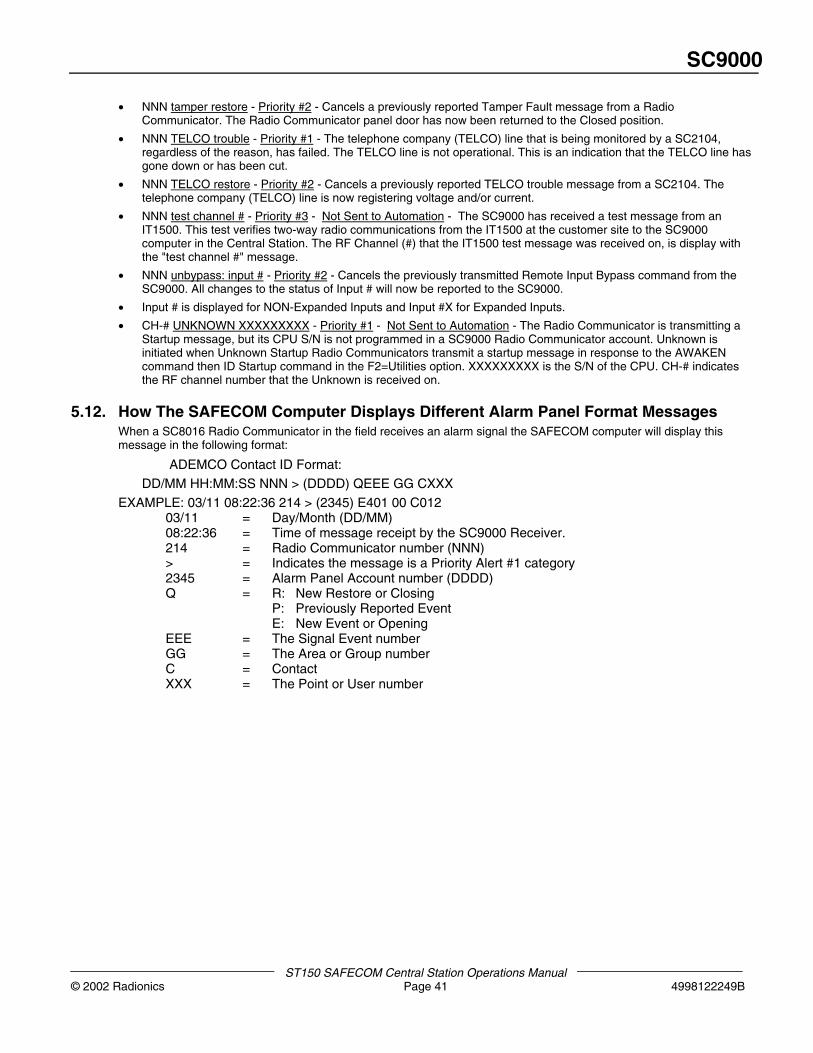
SC9000
ST150 SAFECOM Central Station Operations Manual© 2002 Radionics Page 41 4998122249B
• NNN tamper restore - Priority #2 - Cancels a previously reported Tamper Fault message from a RadioCommunicator. The Radio Communicator panel door has now been returned to the Closed position.
• NNN TELCO trouble - Priority #1 - The telephone company (TELCO) line that is being monitored by a SC2104,regardless of the reason, has failed. The TELCO line is not operational. This is an indication that the TELCO line hasgone down or has been cut.
• NNN TELCO restore - Priority #2 - Cancels a previously reported TELCO trouble message from a SC2104. Thetelephone company (TELCO) line is now registering voltage and/or current.
• NNN test channel # - Priority #3 - Not Sent to Automation - The SC9000 has received a test message from anIT1500. This test verifies two-way radio communications from the IT1500 at the customer site to the SC9000computer in the Central Station. The RF Channel (#) that the IT1500 test message was received on, is display withthe "test channel #" message.
• NNN unbypass: input # - Priority #2 - Cancels the previously transmitted Remote Input Bypass command from theSC9000. All changes to the status of Input # will now be reported to the SC9000.
• Input # is displayed for NON-Expanded Inputs and Input #X for Expanded Inputs.
• CH-# UNKNOWN XXXXXXXXX - Priority #1 - Not Sent to Automation - The Radio Communicator is transmitting aStartup message, but its CPU S/N is not programmed in a SC9000 Radio Communicator account. Unknown isinitiated when Unknown Startup Radio Communicators transmit a startup message in response to the AWAKENcommand then ID Startup command in the F2=Utilities option. XXXXXXXXX is the S/N of the CPU. CH-# indicatesthe RF channel number that the Unknown is received on.
5.12. How The SAFECOM Computer Displays Different Alarm Panel Format MessagesWhen a SC8016 Radio Communicator in the field receives an alarm signal the SAFECOM computer will display thismessage in the following format:
ADEMCO Contact ID Format:
DD/MM HH:MM:SS NNN > (DDDD) QEEE GG CXXX
EXAMPLE: 03/11 08:22:36 214 > (2345) E401 00 C01203/11 = Day/Month (DD/MM)08:22:36 = Time of message receipt by the SC9000 Receiver.214 = Radio Communicator number (NNN)> = Indicates the message is a Priority Alert #1 category2345 = Alarm Panel Account number (DDDD)Q = R: New Restore or Closing
P: Previously Reported EventE: New Event or Opening
EEE = The Signal Event numberGG = The Area or Group numberC = ContactXXX = The Point or User number
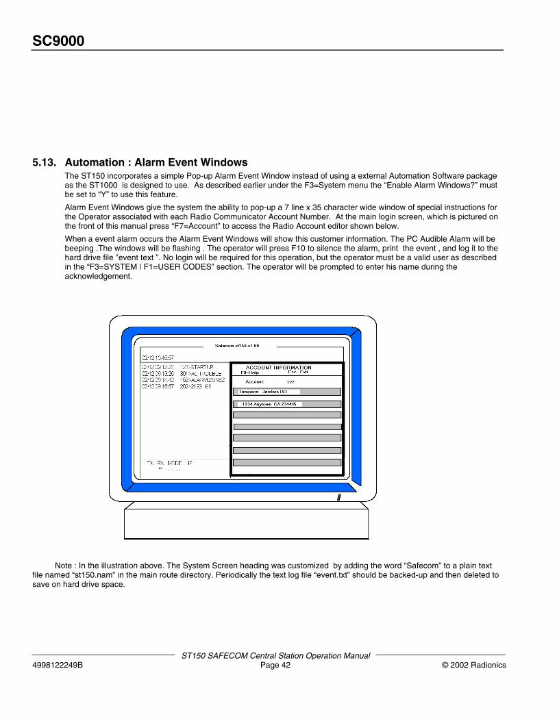
SC9000
ST150 SAFECOM Central Station Operation Manual4998122249B Page 42 © 2002 Radionics
5.13. Automation : Alarm Event WindowsThe ST150 incorporates a simple Pop-up Alarm Event Window instead of using a external Automation Software packageas the ST1000 is designed to use. As described earlier under the F3=System menu the “Enable Alarm Windows?” mustbe set to “Y” to use this feature.
Alarm Event Windows give the system the ability to pop-up a 7 line x 35 character wide window of special instructions forthe Operator associated with each Radio Communicator Account Number. At the main login screen, which is pictured onthe front of this manual press “F7=Account” to access the Radio Account editor shown below.
When a event alarm occurs the Alarm Event Windows will show this customer information. The PC Audible Alarm will bebeeping .The windows will be flashing . The operator will press F10 to silence the alarm, print the event , and log it to thehard drive file ”event text ”. No login will be required for this operation, but the operator must be a valid user as describedin the “F3=SYSTEM | F1=USER CODES” section. The operator will be prompted to enter his name during theacknowledgement.
Note : In the illustration above. The System Screen heading was customized by adding the word “Safecom” to a plain textfile named “st150.nam” in the main route directory. Periodically the text log file “event.txt” should be backed-up and then deleted tosave on hard drive space.

SC9000
ST150 SAFECOM Central Station Operations Manual© 2002 Radionics Page 43 4998122249B

© 2002 Radionics, a division of Detection Systems, Inc.PO Box 80012, Salinas, CA 93912-0012, USACustomer Service: (800) 538-5807 Technical Support: (888) 886-6189
4998122249BST150 OperationsManual
10/02ST150 / SC9000
Page 44 of 44