Embed Size (px)
Citation preview

INDUSTRIAL TRAINING REPORT
LEKAMGE M.S
ST20000442
ASIAN INSTITUTE OF TECHNOLOGY
SCHOOL OF ENGINEERING TECHNOLOGY
DEPARTMENT OF MECHATRONICS

INDUSTRIAL TRAINING REPORT_ST20000442 2
INDUSTRIAL TRAINING REPORT
TRAINEE
NAME : M.S LEKAMGE
STUDENT ID : ST20000442
TRAINING ORGANIZATION
NAME : General Motors Powertrain (Thailand)
BRANCH/DFEPARTMENT : Maintenance
SUPERVISING OFFICER : Mr. Tanate Somchantre
PERIOD OF TRAINING : from 12/05/2014 to 01/08/2014
TRAINING DURATION : 12 weeks
FIELD OF TRAINING : Mechatronics Engineering

INDUSTRIAL TRAINING REPORT_ST20000442 3
ACKNOWLEDGEMENTS
I started my internship at GM powertrain right after finish the 3rd year of my
degree. I finished my 12 weeks of internship period with gaining a lot of knowledge
and experience. During the past 2 months I have realized that learning theoretical
is never the same when it comes to practice.
I would like to express my humble gratitude to Mrs. Sironart (Human resources
manager) for giving me this opportunity to do my internship program in General
Motors Powertrain (GM) and my supervisor Mr. Tanate Somchantra (Facilities
Engineer in GM Powertrain) for giving me valuable advices and patiently guiding
me through while I working here as a trainee. Also I would like to thank Miss. Aor
Wanlapa (Human resources in GM) for helping me in many ways and kindness. It
would not have been possible without the kind support and help of many
individuals and organizations. Not forgotten for all the staffs working at GM. I very
much appreciate for their entire kindness helping and teaching me when I’m
working there. I am highly indebted to GM for their guidance and constant
supervision as well as for providing necessary information regarding the training
period.
INDUSTRIAL TRAINING REPORT_ST20000442 4
ABSTRACT
This report provides a brief description about the General Motors Company
and its Rayong plant. And also this is consist of history of the organization with
mainly focused on the GM Powertrain (Thailand). The discussion then focuses on
manufacturing processes in the Powertrain according to two main categories
which are Machining and Assembly.
This is the structure of the Powertrain
Machining
Head Machining
Crank Machining
Block Machining
Assembly
Assembly loop 1
Sub head
Turbocharger
Piston
Assembly loop 2
Cold testing
Hot test
Packaging
Furthermore this report contains about project what I have done during the
internship period under the Training Experience chapter. Mainly I have tried to
include things I have learnt newly about the industries as well as the product
(engines). And it has described those things highlighting the engineering aspects
and background.

INDUSTRIAL TRAINING REPORT_ST20000442 5
CONTENTS
INTRODUCTION ........................................................................................................................... 7
1.1 Overview of General Motors ................................................................................................... 7
1.1.1 General Motors Mission Statement.................................................................................. 8
1.1.2 General Motors Vision Statement .................................................................................... 8
1.2 GM Powertrain ......................................................................................................................... 9
1.2.1 Factory layout of the Powertrain ...................................................................................... 9
TRAINING EXPERIENCE ......................................................................................................... 10
2.1 Training experience ................................................................................................................ 10
2.2 Project .................................................................................................................................... 11
2.2.1 Introduction of Intelligent Lighting System .................................................................... 11
2.2.2 Limitation (Effect of frequently switching for tube lights).............................................. 12
2.2.3 Solution (Replacing florescent lamps by LED tube lights) ............................................... 12
2.2.4 Motion detecting sensor ................................................................................................. 13
2.2.6 Testing and monitoring ................................................................................................... 16
2.2.7 Problem solving ............................................................................................................... 17
2.1.3 Cost analysis .................................................................................................................... 19
ENGINE ......................................................................................................................................... 20
3.1 History of Engine Operation................................................................................................... 20
3.2 Engine Operation ................................................................................................................... 20
3.2.2 Four Cycle Engines .......................................................................................................... 20
MCHINING SECTION ................................................................................................................ 24
4.1 Engine Head ........................................................................................................................... 24
4.1.1 Engine Head Machining Process ..................................................................................... 25
4.1.2 Machining layout ............................................................................................................ 26
4.2 Engine Crank .......................................................................................................................... 27
4.2.1 Engine crank machining process ..................................................................................... 28

INDUSTRIAL TRAINING REPORT_ST20000442 6
4.3 Engine Block ........................................................................................................................... 29
4.3.1 Block machining process ................................................................................................. 30
ENGINE ASSEMBLY .................................................................................................................. 31
5.1 Engine Head Sub Assembly .................................................................................................... 31
5.1.1 Engine Head Sub Assembly process ................................................................................ 31
5.2 Assembly Loop 1 .................................................................................................................... 32
5.2.1 Assembly Loop 1 process ................................................................................................ 33
5.2.2 Important stations of loop 1 ........................................................................................... 34
5.3 Assembly Loop 2 .................................................................................................................... 38
5.3.1 Assembly loop 2 process ................................................................................................. 38
ENGINE TESTING ...................................................................................................................... 39
6.1 Engine Test History ................................................................................................................ 39
6.2 Engine Cold Test ..................................................................................................................... 40
Mist collector .............................................................................................................................. 42

INDUSTRIAL TRAINING REPORT_ST20000442 7
CHAPTER 1 INTRODUCTION
1.1 Overview of General Motors
Today GM covers many countries in Southeast Asia including Fiji, Laos
Brunei, New Caledonia, Indonesia, Myanmar, Malaysia, Pakistan, Tahiti,
Philippines, Singapore, Japan, Vanuatu and Thailand. The headquarters which leads
GM’s growth in the Southeast Asia region situated in Bangkok, Thailand. The plant
in the Eastern Seaboard Industrial Estate in the Rayong province with a full
manufacturing facility opened on August 3, 2000. Its capacity of 180,000 and today
5,000 of employs team members. And that plant is the GM’s regional hub for
vehicle production.
Chevrolet Zafira MPV was the original product which manufactured in
Rayong plant by GM and in 2003 they have started introduce new models. The
Chevrolet Colorado midsize pickup truck has taken a good place among them.
Currently they produces Chevrolet Sonic, Chevrolet Captiva, Chevrolet Trailblazer
SUV and Cruze passenger cars.

INDUSTRIAL TRAINING REPORT_ST20000442 8
1.1.1 General Motors Mission Statement
1.1.2 General Motors Vision Statement

INDUSTRIAL TRAINING REPORT_ST20000442 9
1.2 GM Powertrain
GM’s first diesel engine plant in the region opened in September 2011 with
200million USD investment. That provides the powertrain facility with capacity of
130,000 engines per year to GM’s Rayong manufacturing plant. They produce new
family of Duramax four-cylinder diesel engines for the first time in the world.
Those engines power the Chevrolet Colorado midsize pickup truck and Trailblazer
SUV which are manufacturing in Rayong plant.
1.2.1 Factory layout of the Powertrain
As in the figure the head machining line, crank machining line and the block
machining line are in the Machining section. In the assembly section there is two
main loop as loop 1 and loop 2. The cold testing of the engine also do during the
assembly loop 2. Apart from that there is small sub head assembly line in that area.
There are few kitting loops also in the assembly section which assemble the piston
and the turbocharger for 2.5L and 2.8L engines. Also there is hot test room which is
doing the hot test as the final step of the manufacturing process.
They maintain the temperature in between 20c to 25c, humidity 50% to
80% RH and 6 to 12 ACH. That helps to keep away the factory from harmful flux for
machines as well as people.

INDUSTRIAL TRAINING REPORT_ST20000442 10
CHAPTER 2
TRAINING EXPERIENCE
2.1 Training experience
Firstly I am very glad to have my internship in General Motors (GM)
Powertrain, Thailand. Actually it was one of my dreams work in an automobile
company.
I was assigned to GM Powertrain as an internship student for a period of 12
weeks starting from 12th of May to 1st of August, 2014. For the past 3 months in GM
Powertrain, I have been in difference section in the powertrain such as machining
section, assembly section, sub assembly section, cold test, hot test and maintenance
section. I have to do an energy saving project during my internship program. I have
implemented an energy saving lighting system successfully for part of the factory.
While my internship program I enjoyed well by studying, learning,
observing, meeting new people and seeing how they contribute to the factory. It
was great experience for my career.
This is my time durations for each sections
Training bay Time period Duration
Head machining 12/05/2014 to 16/05/2014 1 week
Crank machining 19/05/2014 to 23/05/2014 1 week
Block machining 26/05/2014 to 30/05/2014 1 week
Primary Assembly line 02/06/2014 to 13/06/2014 2 weeks
Secondary Assembly line 16/06/2014 to 27/06/2014 2 weeks
Cold testing 30/06/2014 to 11/07/2014 2 weeks
Hot testing 14/07/2014 to 18/07/2014 1 week
Maintenance section 21/07/2014 to 01/08/2014 2 weeks

INDUSTRIAL TRAINING REPORT_ST20000442 11
2.2 Project
I have to do an energy saving project during my internship program. So I
proposed few energy saving projects and I selected an energy saving lighting
system project called ‘Intelligent Lighting System’. I presented my idea about the
project including the cost analysis, expected outcomes and future works. So my
project was in two main categories. First one is reduce energy conservation of
lighting system by installing intelligent lighting system. Second one is replacing
florescent lamps by LED tube lights. The main objective of this project was reduce
the energy consumption of the lighting system.
2.2.1 Introduction of Intelligent Lighting System
Non-operation time
Operation time
When the motion is detected by the motion sensor it send a signal to the
controlling unite which contains relays and timers. Then control unite will turn ON
the light/s. If there is no movement detected in the specific area the light/s will
turn off after a set period of time. And both motion sensor and controlling unite
should connect into a power source.

INDUSTRIAL TRAINING REPORT_ST20000442 12
2.2.2 Limitation (Effect of frequently switching for tube lights)
There is a limitation for the Intelligent Lighting System with the frequently
switching florescent lamps. If going to frequently switch the florescent lamps, its
life time will be reduce according to that graph.
(Source: Lamptech, 2012)
To obtain 100% of rated life we should switch the lights lesser than 8 times
per day. If we switch the lights more than 8 time per day it will reduce the life time
of the lamp. But LED tube lights doesn’t depends on the switching frequency of the
lamp, and also LED tube light has more than 2 times of life time of florescent tube
lights.
2.2.3 Solution (Replacing florescent lamps by LED tube lights)
Currently they have use 56W florescent lamps in the whole factory. If we
can use LED tube lights instead of florescent lamps we need only 15W LED tube
lights to provide the same amount of light. Usually we can use only 50% amount of
light from the florescent lamps and by using reflection techniques we can increase
that amount around 70%. However more than 30% amount of light will be waste.
But from LED lamps we can get 100% efficiency. Because LED lights give the one
direction light. So there won’t be a waste. So that we can use 1350lm LED tube light
instead of 2500lm florescent lamps.
INDUSTRIAL TRAINING REPORT_ST20000442 13
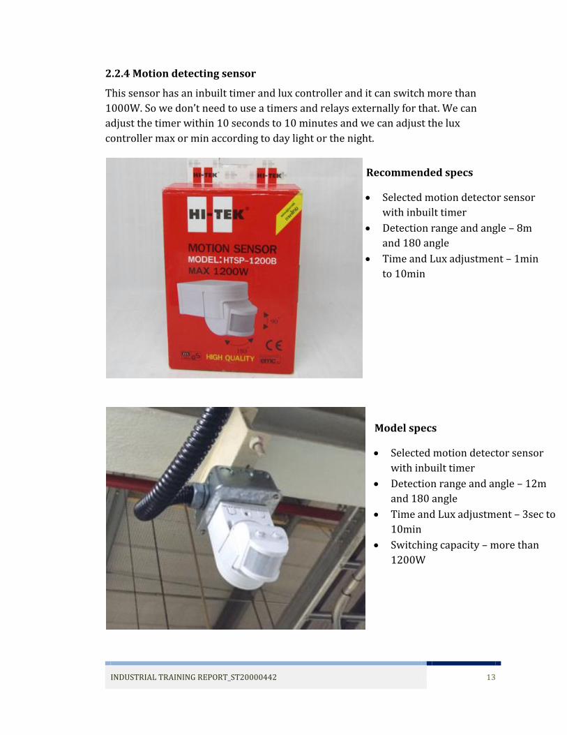
2.2.4 Motion detecting sensor
This sensor has an inbuilt timer and lux controller and it can switch more than
1000W. So we don’t need to use a timers and relays externally for that. We can
adjust the timer within 10 seconds to 10 minutes and we can adjust the lux
controller max or min according to day light or the night.
Recommended specs
Selected motion detector sensor
with inbuilt timer
Detection range and angle – 8m
and 180 angle
Time and Lux adjustment – 1min
to 10min
Switching capacity – more than 700W
Model specs
Selected motion detector sensor
with inbuilt timer
Detection range and angle – 12m
and 180 angle
Time and Lux adjustment – 3sec to
10min
Switching capacity – more than
1200W

INDUSTRIAL TRAINING REPORT_ST20000442 14
2.2.5 Plan
Placing sensors
S1 S2
concrete beam
Side view
switc
h
stairc
ase
co
nc
rete
be
am
0 m
12
5cm
0 m
S2
S1
Top view
Expected area
covered by sensor 1
Expected area covered by sensor 2

INDUSTRIAL TRAINING REPORT_ST20000442 15
Wiring diagram
D2
D1
Expected area covered by sensor 2

INDUSTRIAL TRAINING REPORT_ST20000442 16
2.2.6 Testing and monitoring
I have attached and tested the both sensor and identify the problems
Detection length is not more than 3m
detection angle is about 110 degrees
Sensors can cover lesser than half of the full area

INDUSTRIAL TRAINING REPORT_ST20000442 17
2.2.7 Problem solving
Allover in this project I have used the project implementation method called PDCA
(plan, do, check, action). According to that method I solved the problem by using
QC7 tool.
Fishbone diagram
From this I have sorted out the problem was in the Material which was motion
sensor.

INDUSTRIAL TRAINING REPORT_ST20000442 18
Then I have to do a five why analysis to find a solution for the problem. The five
why analysis was in three main categories which were sensor adjustment, sensor
broken and sensor fault. So I have gave some solutions for all these categories as in
the diagram.
system is not working properly
lights are not switch ON for more than 3m
sensor cannot detect motion more than 3m
sensor adjustments sensor broken sensor fault
actio
n p
lan
rotate sensor
adjust angle
adjust timer
adjust lux
test in dark and light
test the sensor 1
test the sensor 2
check the specs
check the catalog
use more sensors
looking for ananother model ofsensor
manage the areaby these 2 sensors
increase the time delay
why
why
why
statusdetails result statusdetails result statusdetails result
N G
N G
N G
N G
N G
N G
N G
N G
N G
N G
N G
G
G
actio
n p
lan
actio
n p
lan
From this I got a better solutions. The solution was manage the whole area by two
sensors that we had already and increase the time delay. That was implemented
and I got a better result.

INDUSTRIAL TRAINING REPORT_ST20000442 19
2.1.3 Cost analysis
Cost;
2 motion sensors 900 baht
Wires and other parts 200 baht
Total cost 1100 baht
Saving amount;
Wattage of a lamp 56*12 672 W
No of lamps 12 lamps
non-production time 5 hours
Amount pay for 1unit 3.7 baht
The saving amount is depends on how many days they will forget to turn
the lights off before the day-off
This amount of money can save if they forget to turn the lights off about 8
days per month as an average (assumption)
1193.472
0
500
1000
1500
2000
2500
0 2 4 6 8 10 12 14 16
savi
ng
amo
ut
per
yea
r (b
aht)
how many days they will forget to turn the lights off (days/month)
Saving amount
Payback period is 3 months

INDUSTRIAL TRAINING REPORT_ST20000442 20
CHAPTER 3 ENGINE
3.1 History of Engine Operation
The fundamental operation of a reciprocating gasoline engine has not
changed since its birth over 100 years ago. Converting heat energy in hot
expanding gas into rotating mechanical energy is what it does. A reciprocating
engine is basically an air pump - the more air it can pump the more power it can
develop The two biggest areas of technological development that have led to the
development of modern day engines is materials and electronics.
3.2 Engine Operation
3.2.2 Four Cycle Engines
Main types of engines are petrol and diesel. Those are different types of fuel.
Diesel is heavy and dirtier fuel whereas petrol is comparatively high volatile fuel
and gets ignited very easily.
The both types of engines has 4 strokes
1. Inlet
2. Compression
3. Expansion
4. Exhaust

INDUSTRIAL TRAINING REPORT_ST20000442 21
Main differences between Petrol engines and Diesel engines
Stroke Petrol engine Diesel engine
Inlet stoke mixture of air and petrol is
drawn in by the falling piston
only air is drawn in by the falling
piston
Compression
stroke mixture is compressed up to
about 1/8th to 1/12th of its
original size
only air is compressed up to about
1/14th to 1/25th of its original size
Expansion
stroke
the air and fuel mixture is
ignited using a spark plug
and burns expanding and
forcing the piston down
Fuel is injected at a high pressure
into the hot, compressed air in the
cylinder, causing it to burn and
force the piston down. No spark is
required
Exhaust
stroke
the burned mixture of air and fuel is pushed out of the cylinder by
the rising piston
A petrol engine is also known as a “spark ignition” engine. Since a spark plug
is require to ignite the mixture of petrol and air in the combustion chamber.
Whereas a Diesel engine is known as “compression ignition” engine. Since the air is
compressed to very high pressure raising its temperature and then diesel is
injected in very fine spray which causes the diesel to ignite and explode.
Diesel engine

INDUSTRIAL TRAINING REPORT_ST20000442 22
Petrol engine
A diesel engine is more easily turbocharged than a petrol engine. A petrol
engine cannot be easily turbocharged due to the fact that if the compression ratio
and the pressure in the cylinder is too high during the inlet stroke, the mixture
starts to burn too soon, while the piston is on its way up. The diesel engine has no
fuel in the cylinder, thus letting the turbocharger suck as much air as it can without
creating any problems. (A turbo charger is a simple air compressor which
compresses air in the combustion chamber for burning). Some diesel engines also
have an intercooler which helps in blowing cold and oxygen rich air in the
combustion chamber.
Electronic engine management not necessary in diesel engines. Some
modern diesel engines are gaining electronically controlled injection pumps, but
the vast majority of them out there have purely mechanical pumps. In fact no
electricity is required to make a diesel engine run, except for a simple fuel cut off
solenoid so that you can switch the thing off! If your alternator stops working, then
you’re going to get home in a diesel. This also means that a diesel engine does not
have any ignition breakers, ignition coils, distributors and ignition wires to go bad.
So a diesel engine should start no matter if it is dry or rainy or wet.
Petrol destroys lubrication and burns the engine whereas diesel doesn’t. So a diesel
engine would last longer than a petrol engine. Petrol engines are lighter than diesel
engines.

INDUSTRIAL TRAINING REPORT_ST20000442 23
Diesel engines have higher torque than petrol engines. Though the pickup of
a petrol engine would be much more than that of a diesel engine, the diesel engine
would be steady and carry heavier loads to longer distances. Diesel engines have
better fuel efficiency as compared to petrol due to the fact that they have higher
compression ratio. Diesel engines don’t need an ignition system, which reduces
their complexity. But they are noisier and may require frequent maintenance as
compared to petrol engines. Also they are more durable. Diesel engines may also
need glow plugs in extreme cold conditions which heat up the cylinder so that a
cold engine can start easily.

INDUSTRIAL TRAINING REPORT_ST20000442 24
CHAPTER 4 MCHINING SECTION
4.1 Engine Head
This is the second biggest component of the engine. The main parts which
are connected to engine head are camshafts, fuel injectors and inlet/exhaust valves.
And if the engine has a turbocharger it is also connected to the engine head. Engine
head is the upper part of the engine which placed on the engine block.
Synchronization and the accuracy of the engine head should be perfect to achieve
best efficiency of the engine.

INDUSTRIAL TRAINING REPORT_ST20000442 25
4.1.1 Engine Head Machining Process
This is the process of the engine head machining. CNC machining has taken a main
part of the engine head machining process. There are 6 CNC machines in a raw in
the machining line and each one has more than 7 tools. And finally machined head
part reaches the inspection station.
loading rawparts CNC machining
measuring final inspection
unloading

INDUSTRIAL TRAINING REPORT_ST20000442 26
4.1.2 Machining layout

INDUSTRIAL TRAINING REPORT_ST20000442 27
4.2 Engine Crank
Engine crank is place in the engine block which connected to pistons. Rotation of
the crank is the connected to the gear box of a vehicle.

INDUSTRIAL TRAINING REPORT_ST20000442 28
4.2.1 Engine crank machining process
Engine crank machining is more complex than the engine head. Altogether there is
20 stations in this process. Finally it is wash and dry. Then it is going to final
inspection station.
loading rawpartsMill to lengh t,
centering, orital and hollow milling
Cheecking , rough milling mains and
pins, roughing gear ring seat
TT Broach mains incl. undercuts ,
post end and flange end
OD milling pins incl. undercuts,
topping incl. chamfer
Drill & chamfer oil holes
Washing, hardening, tempering
Hardness check
Rolling undercuts and straightening
Re-centering both ends and pre mill
slot at CW
TT Broach mains incl. post end, flange end and gear ring seat
Finish grinding mains, pins
Drill & tap flange bolt holes, drill & ream index holes,
milling keyway, finish mill slot
Finish grinding post end dia &
shoulder, thrust face (gear ring)
Finish grinding post end dia &
shoulder, thrust face (gear ring)
Brush & check
Heat & shrink gear ring
BalancingPolish mains, pins,
thrust face and flange
Wash & dry
Final inspection Unloading part

INDUSTRIAL TRAINING REPORT_ST20000442 29
4.3 Engine Block
Engine block is the biggest part of the engine from the size as well as the weight.
This is the base of the engine. Pistons, crank, oil pan… etc. installed into the engine
block.

INDUSTRIAL TRAINING REPORT_ST20000442 30
4.3.1 Block machining process
This process also have more than 15 stations. They are fully automated and
driven by a conveyers and pick and place robots. This machining line also have an
alarm system which can indicate any problem in the machine or the part. This
process includes a testing station in the final stage. This station operate by a kuka 5
axis robot and it automatically identifies defects.
loading rawparts CNC machining convayer
CNC machining convayer CNC machinig
washing convayer CNC machining
measuring cylinder honing finishing
measuring crank bar washig pressing plugs
leak testing unloading

INDUSTRIAL TRAINING REPORT_ST20000442 31
CHAPTER 5 ENGINE ASSEMBLY
5.1 Engine Head Sub Assembly
5.1.1 Engine Head Sub Assembly process
This is a small process in the engine assembly section. In here they install
lower retainers, cam cover dowel pin, valve seals, springs, upper retainers,
intake/exhaust valves into the engine head and finally it is tested in leaks and laser
key check.
Load HeadInstall Lower Retainers, Cam
Cover Dowel PinInstall Valve Seals
Install Springs Install Upper Retainers & Keys Install Intake / Exhaust Valves
Laser Key Check Leak Test Cylinder Head Repair Station
Unload Head

INDUSTRIAL TRAINING REPORT_ST20000442 32
5.2 Assembly Loop 1
Engine assembly loop 1 is the most important part from the engine
assembly process. All the main parts of engine such as engine block, engine crank
and engine head are assmble in this process. More than 80% percent of assembly
process done in loop 1. There is a special order to install the engine parts. And
there are work stations according to that order. This assembly line is also semi
automated as same as other assembly lines. There is a one worker for every and
each station and he has the responsible of the duty of his station. That assembly
loop assemble about 80% completed engine starting from the engine block. Kitting
loop 1 and loop 2 are also doing a effective job by suppling engine parts to related
stations.

INDUSTRIAL TRAINING REPORT_ST20000442 33
5.2.1 Assembly Loop 1 process
Block Load Crank loadMain Bearing cap
install
Piston Install Rod caps install Water pump Install
Rear Seal Carrier Cover Install
Oil Buffle Install Upper Oil Pan Install
Head load Head Bolt Rundown Camshaft install
Cam Cap Bridge Install Timing Belt Install Cam Cover Install
Dust Cover Install Intake InstallHigh Pressure Fuel
Line Install
Water Pump Inlet Pipe Install
EGR InstallLow pressure fuel line
Install
Oil pick up tube install Lower Oil Pan Install Unloadinig

INDUSTRIAL TRAINING REPORT_ST20000442 34
5.2.2 Important stations of loop 1
Crank load
Piston Install
Water pump Install

INDUSTRIAL TRAINING REPORT_ST20000442 35
Oil Baffle Install
Head load
Camshaft install

INDUSTRIAL TRAINING REPORT_ST20000442 36
Timing Belt Install
Intake Install
High Pressure Fuel Line Install

INDUSTRIAL TRAINING REPORT_ST20000442 37
EGR Install
Lower Oil Pan Install

INDUSTRIAL TRAINING REPORT_ST20000442 38
5.3 Assembly Loop 2
Final few steps of the engine assembly process are done in this loop. Cold
Test and the installation of Turbocharger have taken important part of this loop.
Apart from that prepare for cold test, punching the engine number, etc. done in
here. The cold test is done by fully automatically and result data of the test are
automatically update to the server. By the way defective engines which are failed
from the test rejects from the assembly loop by itself.
5.3.1 Assembly loop 2 process
Loading Cold TestInstall Shipping Cap to
Fuel return line
Install Shipping Cap to Fuel Pump Inlet
Flywheel/Flex Plate Install and Engrave
EUN#
Exhaust & Turbo Install
Turbo Oil Feed Tube Install
Turbo Leak Test Install Turbo brace
Turbo brace boltsTurbo Oil Drain Back
InstallUnloading
INDUSTRIAL TRAINING REPORT_ST20000442 39
CHAPTER 6 ENGINE TESTING
6.1 Engine Test History
Before 1980 the hot test which was known as Bathtub test was in end of the
assembly line. There was no load test or cold test. And just look for leaks and listen
for noises. In 19th century new technologies have introduced for leak test and load
test. Those were fully automatic loaded dyno hot test. And snap shot data save to
server. In 1990 – 1995 the cold test was introduced and it performed end of the
assembly line instead of hot test. It was able to achieve excellent quality results.
And also it has the ability identify bad designs and the bad quality of suppliers.
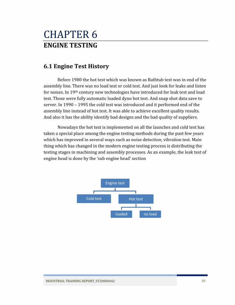
Nowadays the hot test is implemented on all the launches and cold test has
taken a special place among the engine testing methods during the past few years
which has improved in several ways such as noise detection, vibration test. Main
thing which has changed in the modern engine testing process is distributing the
testing stages in machining and assembly processes. As an example, the leak test of
engine head is done by the ‘sub engine head’ section
Engine test
Cold test Hot test
loaded no load

INDUSTRIAL TRAINING REPORT_ST20000442 40
6.2 Engine Cold Test
Cold test doesn’t identify the errors by itself, it is part of the whole process
to insure engines are built correctly. Cold test spins the engine with an external
driver while monitoring the following basic test signals:
intake pressure
exhaust pressure
oil pressure
motoring torque
vibration or noise
ignition signals
crankshaft sensor signal
camshaft sensor signal
The test stand computer generates control signals to operate engine
subsystems like the ignition and cam phases. The basic test signals are monitored
and analyzed by the cold test stand computer as the engine is motored and the
waveforms acquired have features that are used to establish test points. Data
acquisition is synchronized to the engine crankshaft (crank angle based sampling)
and test points are compared to high and low limits. That is based on limit
comparisons the engine is either accepted as normal or rejected as abnormal.
Test results and waveforms are stored on the test stand computer and sent
to the host computer for longer term storage also service functions or repairs are
logged into the host computer using repair codes and stored with the test record.
Rejected engines will go to a service loop or repair area for examination or repair
by a service person. The service loop computer retrieves the test history for the
engine being serviced from the host computer. The engine is retested in the cold
test stand after being in the service loop and reevaluated as normal or abnormal.
And the mechanical portion of a cold test stand is a precision machine tool with
details that accurately locate an engine for test. All locator and probe positions in a
cold test stand must be precise and repeatable from engine to engine. The
mechanical heart of the test stand is the drive line. It must be balanced, quiet,
smooth running and powerful enough to motor an engine at any speed from 0 to
2500 rpm with little to no speed variation. Mechanical clamps securely lock the
engine into the test stand mechanical fingers connect the test stand drive line to
the engine flywheel or flex plate.

INDUSTRIAL TRAINING REPORT_ST20000442 41
Mechanical slides with seals probe the intake and exhaust ports of the
engine to be tested by blocking valves on the intake and exhaust probes allow
control of air flow in the engine during test. Mechanical slide with probe connects
to the engine oil pressure port and mechanical slides position vibrations sensors
(accelerometers) against the engine cylinder head and cylinder block. Mechanical
slides electrically connect the crankshaft sensors, ignition coils and cam phase oil
control valves (ocv) to the test stand computer. Mechanical slide positions
inductive sensors near the ignition coils to detect the spark plug firing signal. The
supercharging valves route compressed air to the engine intake to increase
cylinder pressure during testing. Some test stands use rigging harnesses and match
plates for electrical connections where automatic probes won’t work and some test
stand designs lift the engine from the pallet to improve noise and vibration testing.
The cold test drive line uses a mechanical overload or clutch to protect
against excessive overloads like an engine lock up. A cold test stand is basically a
machine tool and incorporates similar hardware like a PLC and I/O, relays,
solenoids, limit switches, power supplies, and fuses disconnects and power
distribution hardware. The PLC controls all machine motions, the drive motor and
rf tag operations and communicates with the test stand computer. The cold test
drive motor and drive controller spin the engine at desired speeds for the different
tests. The drive system has an encoder that supplies the test stand computer with
engine crankshaft speed and position information. The pressure transducers
monitor engine intake, exhaust and oil pressure sending electrical pressure signals
to the test stand computer. Oil temperature sensor allows for pressure
compensation due to variation in temperature and oil viscosity. Weather station
monitors air temperature, pressure and humidity to compensate intake and
exhaust pressure readings for changes in atmospheric pressure. Instrumentation
hardware conditions the transducer and sensor signals and it amplifiers isolate the
test stand computer from electrical noise and spikes. The test stand computer
controls all the test sequences and drive speeds via the PLC and it collects all the
test data, does the analysis and accepts or rejects the engine being tested.
INDUSTRIAL TRAINING REPORT_ST20000442 42
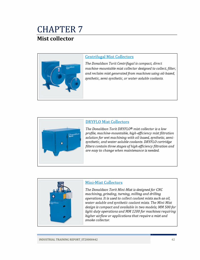
CHAPTER 7 Mist collector

INDUSTRIAL TRAINING REPORT_ST20000442 43


