Embed Size (px)
Citation preview
AN1075/1098 1/98
APPLICATION NOTE
USING THE ST9+ MEMORY MANAGEMENT UNIT(EXAMPLES FOR ST92195 AND ST92R195)
INTRODUCTION
This application note describes techniques for creating software applications using theMemory Management Unit (MMU) of the ST9+. In addition, it provides useful hints on usingthe ST9+ C Compiler.
A description of the main characteristics of the ST9+ MMU will be given. Then, the C compilerwill be briefly described, emphasizing the Memory Management Unit aspects. Finally, the sub-ject matter is developed using examples for a ROMless and a ROM microcontroller, theST92R195 and the ST92195 respectively.
After reading this document you should be able to understand the key features of the MMU,how to manipulate the different MMU pointers and develop a software application on any ST9+in a secure way with version V4.2 of the ST9+ GNU C Compiler.
To better understand and apply the features implemented in this application note, both aknowledge of the ST9+ architecture and the GNU C Compiler for ST9+ are necessary.
1

2/98
Table of Contents
98
2
INTRODUCTION . . . . . . . . . . . . . . . . . . . . . . . . . . . . . . . . . . . . . . . . . . . . . . . . . . . . . . . 1
1 DEFINITIONS AND ABBREVIATIONS . . . . . . . . . . . . . . . . . . . . . . . . . . . . . . . . . . . . 5
2 A BRIEF TOUR OF THE ST9+ MMU . . . . . . . . . . . . . . . . . . . . . . . . . . . . . . . . . . . . . . 6
2.1 THE INSTRUCTION SET AND THE MMU . . . . . . . . . . . . . . . . . . . . . . . . . . . . . . 6
2.1.1 Instruction cycle times . . . . . . . . . . . . . . . . . . . . . . . . . . . . . . . . . . . . . . . . . . . . . . . .82.1.2 New ST9+ instructions summary . . . . . . . . . . . . . . . . . . . . . . . . . . . . . . . . . . . . . . . . 92.1.3 The User Flag . . . . . . . . . . . . . . . . . . . . . . . . . . . . . . . . . . . . . . . . . . . . . . . . . . . . . .9
2.2 INTERRUPTS AND THE MMU . . . . . . . . . . . . . . . . . . . . . . . . . . . . . . . . . . . . . 10
2.3 THE MEMORY MANAGEMENT UNIT . . . . . . . . . . . . . . . . . . . . . . . . . . . . . . . . 10
2.3.1 The need for an MMU . . . . . . . . . . . . . . . . . . . . . . . . . . . . . . . . . . . . . . . . . . . . . . .112.3.2 Accessing Functions . . . . . . . . . . . . . . . . . . . . . . . . . . . . . . . . . . . . . . . . . . . . . . . .122.3.3 Accessing the data . . . . . . . . . . . . . . . . . . . . . . . . . . . . . . . . . . . . . . . . . . . . . . . . . .132.3.4 Swapping the DPRs and the PDRs . . . . . . . . . . . . . . . . . . . . . . . . . . . . . . . . . . . . . 142.3.5 The Bootrom . . . . . . . . . . . . . . . . . . . . . . . . . . . . . . . . . . . . . . . . . . . . . . . . . . . . . .15
2.4 EXTERNAL MEMORY INTERFACE . . . . . . . . . . . . . . . . . . . . . . . . . . . . . . . . . 15
2.5 PROGRAM/DATA SELECTION . . . . . . . . . . . . . . . . . . . . . . . . . . . . . . . . . . . . . 16
2.5.1 SPM /SDM and the standard instructions . . . . . . . . . . . . . . . . . . . . . . . . . . . . . . . . 162.5.2 The stacks . . . . . . . . . . . . . . . . . . . . . . . . . . . . . . . . . . . . . . . . . . . . . . . . . . . . . . . .172.5.3 LDDD, LDPD, LDDP, LDPP instructions . . . . . . . . . . . . . . . . . . . . . . . . . . . . . . . . . 182.5.4 Interrupts and the Program/Data management . . . . . . . . . . . . . . . . . . . . . . . . . . . . 20
3 THE V4.2 ST9+ GNU C COMPILER . . . . . . . . . . . . . . . . . . . . . . . . . . . . . . . . . . . . . 21
3.1 V4.2 GNU C COMPILER FEATURES AT A GLANCE . . . . . . . . . . . . . . . . . . . 21
3.2 OPTIONS TO USE . . . . . . . . . . . . . . . . . . . . . . . . . . . . . . . . . . . . . . . . . . . . . . . 21
3.2.1 Compiler Options . . . . . . . . . . . . . . . . . . . . . . . . . . . . . . . . . . . . . . . . . . . . . . . . . . .213.2.2 Linker Options . . . . . . . . . . . . . . . . . . . . . . . . . . . . . . . . . . . . . . . . . . . . . . . . . . . . .22
3.3 HOW TO MANAGE THE MMU WITH THE COMPILER . . . . . . . . . . . . . . . . . . 22
3.3.1 MMU models handled by the V4.2 compiler . . . . . . . . . . . . . . . . . . . . . . . . . . . . . . 223.3.2 Managing Functions . . . . . . . . . . . . . . . . . . . . . . . . . . . . . . . . . . . . . . . . . . . . . . . . .223.3.3 Managing Data . . . . . . . . . . . . . . . . . . . . . . . . . . . . . . . . . . . . . . . . . . . . . . . . . . . . .23
3.4 MAPPING YOUR APPLICATION WITH THE LINKER . . . . . . . . . . . . . . . . . . . 23
3.4.1 The possible data/code sections and their mapping . . . . . . . . . . . . . . . . . . . . . . . . 233.4.2 Notes on using Initialized Variables . . . . . . . . . . . . . . . . . . . . . . . . . . . . . . . . . . . . . 263.4.3 A tentative set of general rules . . . . . . . . . . . . . . . . . . . . . . . . . . . . . . . . . . . . . . . . 28
3.5 SUMMARY OF V4.2 ST9+ GNU C COMPILER LIMITATIONS . . . . . . . . . . . . . 29
3/98
Table of Contents
4 FIRST EXAMPLE: THE ST92195 . . . . . . . . . . . . . . . . . . . . . . . . . . . . . . . . . . . . . . . . 30
4.1 MEMORY MAPPING . . . . . . . . . . . . . . . . . . . . . . . . . . . . . . . . . . . . . . . . . . . . . 30
4.2 DESCRIPTION OF THE APPLICATION . . . . . . . . . . . . . . . . . . . . . . . . . . . . . . 31
4.3 MMU SETTINGS ON THE ST92195 . . . . . . . . . . . . . . . . . . . . . . . . . . . . . . . . . 31
4.4 MAPPING THE APPLICATION WITH THE SCRIPTFILE . . . . . . . . . . . . . . . . . 33
4.5 INITIALIZED VARIABLES . . . . . . . . . . . . . . . . . . . . . . . . . . . . . . . . . . . . . . . . . 37
4.6 COMPILER AND LINKER OPTIONS . . . . . . . . . . . . . . . . . . . . . . . . . . . . . . . . . 38
4.7 APPLICATION FILES . . . . . . . . . . . . . . . . . . . . . . . . . . . . . . . . . . . . . . . . . . . . 38
4.8 EMULATOR CONFIGURATION FILE . . . . . . . . . . . . . . . . . . . . . . . . . . . . . . . . 39
5 SECOND EXAMPLE: THE ST92R195 . . . . . . . . . . . . . . . . . . . . . . . . . . . . . . . . . . . . 40
5.1 ST92R195 MEMORY MAPPING . . . . . . . . . . . . . . . . . . . . . . . . . . . . . . . . . . . . 40
5.2 APPLICATION DESCRIPTION . . . . . . . . . . . . . . . . . . . . . . . . . . . . . . . . . . . . . 41
5.3 MANAGING FUNCTIONS . . . . . . . . . . . . . . . . . . . . . . . . . . . . . . . . . . . . . . . . . 41
5.3.1 Using function pointers . . . . . . . . . . . . . . . . . . . . . . . . . . . . . . . . . . . . . . . . . . . . . .42
5.4 MANAGING DATA . . . . . . . . . . . . . . . . . . . . . . . . . . . . . . . . . . . . . . . . . . . . . . . 47
5.4.1 C and Assembly directives for managing the data. . . . . . . . . . . . . . . . . . . . . . . . . . 495.4.2 Managing the data pointer changes. . . . . . . . . . . . . . . . . . . . . . . . . . . . . . . . . . . . . 495.4.3 Data Page Registers and Port Data Registers . . . . . . . . . . . . . . . . . . . . . . . . . . . . 51
5.5 MAPPING THE APPLICATION WITH THE SCRIPTFILE . . . . . . . . . . . . . . . . . 52
5.6 LIBRARIES . . . . . . . . . . . . . . . . . . . . . . . . . . . . . . . . . . . . . . . . . . . . . . . . . . . . . 54
5.7 THE COMPILER AND LINKER OPTIONS . . . . . . . . . . . . . . . . . . . . . . . . . . . . 54
5.8 APPLICATION FILES . . . . . . . . . . . . . . . . . . . . . . . . . . . . . . . . . . . . . . . . . . . . 55
5.9 THE DEBUGGER CONFIGURATION FILE . . . . . . . . . . . . . . . . . . . . . . . . . . . . 55
3
4/98
Table of Contents
98
6 APPENDIX - SOURCE FILES . . . . . . . . . . . . . . . . . . . . . . . . . . . . . . . . . . . . . . . . . . 56
6.1 COMMON SOURCE FILES . . . . . . . . . . . . . . . . . . . . . . . . . . . . . . . . . . . . . . . . 56
6.1.1 DEFINE.H . . . . . . . . . . . . . . . . . . . . . . . . . . . . . . . . . . . . . . . . . . . . . . . . . . . . . . . .566.1.2 MMU.H . . . . . . . . . . . . . . . . . . . . . . . . . . . . . . . . . . . . . . . . . . . . . . . . . . . . . . . . . . .576.1.3 ST9MACRO.H . . . . . . . . . . . . . . . . . . . . . . . . . . . . . . . . . . . . . . . . . . . . . . . . . . . . .606.1.4 DISPLAY.H . . . . . . . . . . . . . . . . . . . . . . . . . . . . . . . . . . . . . . . . . . . . . . . . . . . . . . .61
6.2 THE FIRST APPLICATION EXAMPLE SOURCE FILES : THE ST92195 . . . . 62
6.2.1 MAIN.C . . . . . . . . . . . . . . . . . . . . . . . . . . . . . . . . . . . . . . . . . . . . . . . . . . . . . . . . . .626.2.2 ACTIONS.C . . . . . . . . . . . . . . . . . . . . . . . . . . . . . . . . . . . . . . . . . . . . . . . . . . . . . . .666.2.3 CONST.C . . . . . . . . . . . . . . . . . . . . . . . . . . . . . . . . . . . . . . . . . . . . . . . . . . . . . . . . .686.2.4 DISPLAY.C . . . . . . . . . . . . . . . . . . . . . . . . . . . . . . . . . . . . . . . . . . . . . . . . . . . . . . .70
6.3 THE SECOND APPLICATION EXAMPLE SOURCE FILES : THE ST92R195 78
6.3.1 MAIN.C . . . . . . . . . . . . . . . . . . . . . . . . . . . . . . . . . . . . . . . . . . . . . . . . . . . . . . . . . .786.3.2 CONST.C . . . . . . . . . . . . . . . . . . . . . . . . . . . . . . . . . . . . . . . . . . . . . . . . . . . . . . . . .896.3.3 MENU1.C . . . . . . . . . . . . . . . . . . . . . . . . . . . . . . . . . . . . . . . . . . . . . . . . . . . . . . . . .906.3.4 MENU2.C . . . . . . . . . . . . . . . . . . . . . . . . . . . . . . . . . . . . . . . . . . . . . . . . . . . . . . . . .906.3.5 CODE04.C . . . . . . . . . . . . . . . . . . . . . . . . . . . . . . . . . . . . . . . . . . . . . . . . . . . . . . . .91
4
5/98
Definitions and Abbreviations
1 DEFINITIONS AND ABBREVIATIONS
– Far function: A function that is defined in a 64K segment, and that can be called by a func-tion from another 64K segment. This function is ended by the rets instruction.
– Far call: A call to a function located in a different 64K segment
– MMU: Memory Management Unit
– Bankswitch: An ST9 pointing mechanism for managing large code applications
– Physical address: A 22-bit address used to access the physical internal or external mem-ory.
– Logical address: A 16-bit address, used in instructions, that is translated into a physical ad-dress for accessing physical memory.
6/98
A BRIEF TOUR OF THE ST9+ MMU
2 A BRIEF TOUR OF THE ST9+ MMU
This section gives a summary of the key features of the ST9+ MMU.
2.1 THE INSTRUCTION SET AND THE MMU
The ST9+ instruction set is fully compatible with the ST9. This means that all applications run-ning on ST9 may be run on ST9+. In fact, the instruction set of the ST9 has been improved inthe ST9+ to increase its power in terms of speed, code size, and debug support. Also, theMMU allows you to easily implement applications with large code size using dedicated instruc-tions for accessing far objects.
The new ST9+ instructions are:
LINK
This instruction was added to reduce C function transfer overhead. It implements the prologueof a C function, that needs to reserve a defined number of bytes in system stack for passingparameters and local variables.
The operation performed for each C function in a prologue is:pushw rr12 step (1)
ldw rr12, SSPR step (2)
subw SSPR, #N step (3)
Thus, this would represent 9 bytes per prologue and 36 clock cycles.
It can now be done by:link rr12, #N
which takes 3 bytes and 16/12 clock cycles depending if the stack is in the register file or inmemory.
UNLINK
This instruction is used in the epilogue of the C function, which is equivalent to the comple-ment of the LINK instruction. It is also made for reducing the code size overhead and increasethe execution speed of the C functions.
The UNLINK replaces:
ldw SSPR, rr12
popw rr12
and is used by doing:unlink rr12
In this case the amount of bytes saved is 2 and the number of clock cycles is between 14 and18, depending on whether the stack is in the register file or in memory.
7/98
A BRIEF TOUR OF THE ST9+ MMU
LINKU - same as link instruction for the user stack
UNLINKU - same the unlink instruction for the user stack
JPS
The JPS instruction is an inter-segment jump. This means that this instruction does a jump toa specified offset inside a specified page.
For example:rr0 = 3000h
r2 = 20h
jps (rr0), r2
will do a jump to segment 20h at address 3000h inside this 64K segment
CALLS
The CALLS instruction allows you to do an inter-section call, that is a call to a function that islocated in a different 64K segment.
For example:rr0 = 3000h
r2 = 20h
calls (rr0), r2
will call the function pointed to by rr0 in segment 20h.
Note that the CALLS stacks both the return address, and the current segment number.
RETS
The RETS instruction is used to return from a function that is called by the CALLS instruction.It restores both the return address, and the segment to return to.
Note that it is used simply as RETS, without source or destination parameters.
WARNING : If a function is ended by a RETS, then all calls to this function should be done bythe CALLS instruction. Otherwise, if a CALL instruction is done, it will only stack the return ad-dress, but the RETS instruction will try to restore both the return address and the segmentnumber.
8/98
A BRIEF TOUR OF THE ST9+ MMU
2.1.1 Instruction cycle times
Instruction cycle times have been optimized in the ST9+ core to increase the CPU speed.
You should be aware that even if the source code is fully compatible with the ST9 core, if rou-tines use delay loops based on instruction cycle times, they will have to be modified.
An exhaustive list of the differences will not be given here. You should refer to the ST9+ pro-gramming manual to get this information.
As a guideline, you can consider that, with the same external clock, the speed increase of theST9+ is about x1.5, compared to the ST9 instruction set. This evaluation is based on generalroutines written in assembler or C. However, it is important to know that the difference is spe-cific to each instruction.
For example:or r,r
lasts 6 clock cycles on ST9 and only 4 clock cycles on ST9+, butrlcw rr
lasts 8 clock cycles on ST9 and also 8 clock cycles on ST9+.
9/98
A BRIEF TOUR OF THE ST9+ MMU
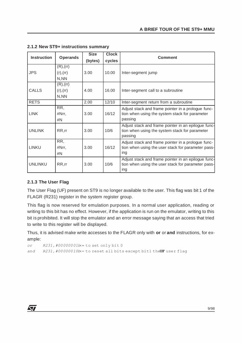
2.1.2 New ST9+ instructions summary
2.1.3 The User Flag
The User Flag (UF) present on ST9 is no longer available to the user. This flag was bit 1 of theFLAGR (R231) register in the system register group.
This flag is now reserved for emulation purposes. In a normal user application, reading orwriting to this bit has no effect. However, if the application is run on the emulator, writing to thisbit is prohibited. It will stop the emulator and an error message saying that an access that triedto write to this register will be displayed.
Thus, it is advised make write accesses to the FLAGR only with or or and instructions, for ex-ample:or R231,#00000001b <= to set only bit 0
and R231,#00000010b <= to reset all bits except bit1 the UF user flag
Instruction OperandsSize
(bytes)
Clock
cyclesComment
JPS
(R),(rr)
(r),(rr)
N,NN
3.00 10.00 Inter-segment jump
CALLS
(R),(rr)
(r),(rr)
N,NN
4.00 16.00 Inter-segment call to a subroutine
RETS 2.00 12/10 Inter-segment return from a subroutine
LINK
RR,
#Nrr,
#N
3.00 16/12Adjust stack and frame pointer in a prologue func-tion when using the system stack for parameterpassing
UNLINK RR,rr 3.00 10/6Adjust stack and frame pointer in an epilogue func-tion when using the system stack for parameterpassing
LINKU
RR,
#Nrr,
#N
3.00 16/12Adjust stack and frame pointer in a prologue func-tion when using the user stack for parameter pass-ing
UNLINKU RR,rr 3.00 10/6Adjust stack and frame pointer in an epilogue func-tion when using the user stack for parameter pass-ing
10/98
A BRIEF TOUR OF THE ST9+ MMU
2.2 INTERRUPTS AND THE MMU
There are some differences between the ST9 and ST9+ interrupts. The first main difference isthat in ST9 instructions cannot be interrupted by the CPU. In the ST9+, instructions can be in-terrupted if they have not already modified the memory or the register file.
Also an option bit allows you to configure two different ways of handling interrupts, dependingon an option bit ENCPR, located in the EMR2 register of the Memory Management Unit.
In order to simplify the understanding of this, it can be considered that, by default, the behav-iour of the interrupt handling in the ST9+ is fully compatible to the one in the ST9.
There is however one restriction to the MMU: it is not possible to use far calls (CALLS) insidean interrupt service routine.
So, for example, on an MCU with only 64K of program memory like the ST92E195, there is nodifference between ST9 and ST9+.
On ST9+, a specific register is dedicated to pointing to the interrupt service routines.
This 16-bit register ISR (stands for Interrupt Segment Register) always points to a user de-fined 64K segment, where the interrupt vectors and interrupt service routines should be lo-cated.
Then depending on the ENCPR option bit, there are 2 cases:
– ENCPR = 0When entering into the interrupt service routine, ISR is simply used instead of CSR. This isST9 compatible. In this case, it is not possible to use far calls in interrupt service rou-tine because the CSR is not stacked. Only the return address (16-bit) and the flags (8-bit)are saved into the system stack.
– ENCPR = 1CSR is first pushed onto the stack and then takes the value of the ISR register. In this casethe interrupt stacks both the return address (16-bit), the segment (8-bit) and the flags (8-bit).
Refer to the Memory Management Unit chapter of any ST9+ datasheet for more information.
Warning: If you need to use the large code model (with more than 64K of code), then all func-tions will be automatically defined as far functions by the compiler. In this case you will haveto use the large model for interrupts too (ENCPR = 1), i.e. because interrupt routines that usefar functions must imperatively use the large model.
2.3 THE MEMORY MANAGEMENT UNIT
This section will not describe the MMU completely, but will try to highlight the key pointsneeded to fully understand the examples, and the requirements imposed on the compiler.

11/98
A BRIEF TOUR OF THE ST9+ MMU
2.3.1 The need for an MMU
The ST9 is a 16-bit address CPU, which means that only 64K linear memory blocks can be ac-cessed.
To remove this limitation, a mechanism, the ”bankswitch”, was used in the ST9 to access upto 8 Mbytes of code.
This mechanism was based on a segmentation of the memory into two types:
– A static block (32K): accessible at any time
– Several dynamic blocks (32K): accessible only through a specific sequence in static block.
There was no specific instruction to access dynamic blocks and the access was user defined,always via the static bank. This static bank being only 32K wide, the restriction was important.
To get around these restrictions and to access more than 64K of memory more easily and ef-ficiently, while keeping the fast and cost-effective architecture of the ST9, the Memory Man-agement Unit was built.
This MMU allows you to access up to 4 Mbytes (22-bit address) of code in an almost linearmanner, that is through specific instructions, providing a transparent way of managing func-tions. Data are pointed to by four data pointers that can address the whole 4 Mbyte memoryrange.
Seen in a simplified way, in the ST9+ we now have 22-bit addressing (16+6 bits) for code anddata accesses. Code addresses are almost linear and data addresses are paginated.
12/98
A BRIEF TOUR OF THE ST9+ MMU
2.3.2 Accessing Functions
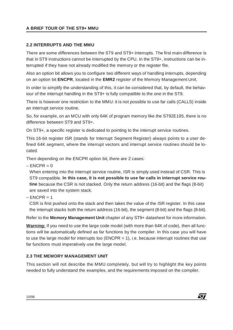
A 6-bit register, the CSR (Code Segment Register) is dedicated to pointing to the 64 Kbytesegment in use. Modification of this register is done only through 3 instructions: JPS, CALLSand RETS.
Thus, to access a function located in a different segment, you must use the CALLS or JPS in-structions. These instructions modify the CSR value, pointing to the new segment to accessand jump to the offset specified. If a CALLS is done, both the return address and the old CSRvalue will be stacked.
Keep in mind that if a function is called with CALLS it must be ended by a RETS to keep thestack frame coherent (the standard CALL instruction stacks only the return address, NOT theCSR).
WARNING : It is prohibited to modify the CSR directly, using standard instructions. OnlyCALLS , and JPS can modify it! Any modification of this register will completely lose control ofthe segment location, and therefore Program Counter may not point to the correct segment.
Two different cases are now presented to the user:
– The application uses less than 64K of program:No impact on the software, all functions are called with the CALL instruction and are endedby RET.
– The application uses more than 64K of program:With the compiler, it will be seen later on, that only Far functions (CALLS, RETS) will be used,except for static functions, that are normal functions (CALL, RET).
13/98
A BRIEF TOUR OF THE ST9+ MMU
2.3.3 Accessing the data
To properly understand data management with the MMU, we must consider 2 types of ad-dresses for the same data:
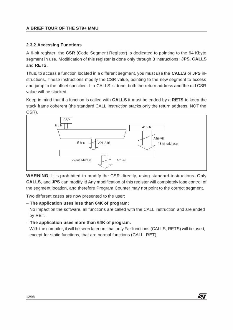
– The physical address: this is the address that is effectively put onto the memory bus (22-bit). This address is the concatenation of the 14 least significant bits of the logical addressand the 8 bits of one of the 4 Data Page Registers (DPR0-3).
– The logical address: this is the address that will be given to the instruction (16-bit). It is only16 bits long. The identification of which data pointer will be used to recreate the physical ad-dress is made through the 15th and 14th bits, according to the following table:
Thus, any instruction that uses a 16-bit address between:
0x0000 and 0x3FFF will select DPR00x4000 and 0x7FFF will select DPR10x8000 and 0xCFFF will select DPR20xD000 and 0xFFFF will select DPR3
It will also be seen later on, that the linker allows you to force a data object to be accessed bya specific DPR, whatever its physical address.
Any DPR can point to any 16 Kbyte page of any 64 Kbyte segment. The logical address se-lects both which DPR to use (15th and 14th bits), and the 14-bit offset inside a block of 16Kbytes.
In this way, with a fixed logical address, by selecting the proper DPR value, it is possible to ac-cess 256 different locations in the 4 Mbyte memory (8 bits of the DPR).
15th bit 14th bit DPR selected0 0 00 1 11 0 21 1 3
14/98
A BRIEF TOUR OF THE ST9+ MMU
For example:
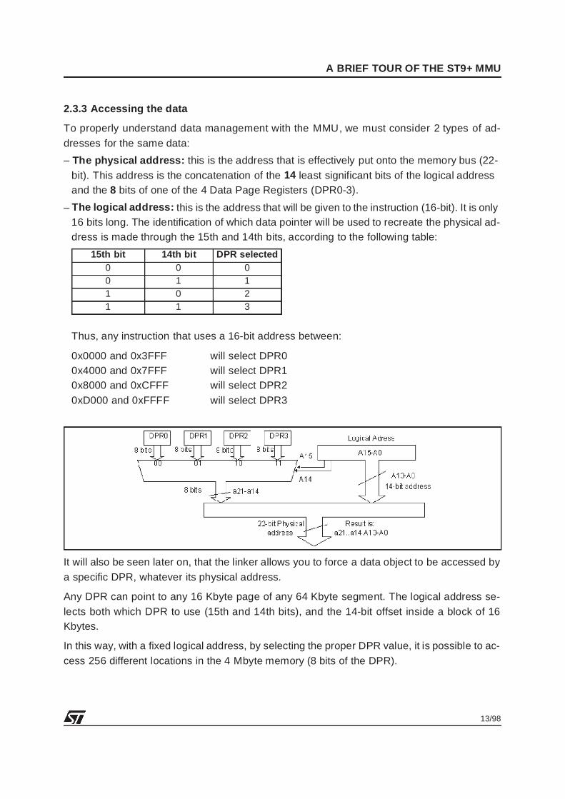
If the logical address of FOO is 1000100010001000b (0x8888), then bits 15 and 14 selectDPR2 (10) automatically.
The offset inside the 16 Kbyte page, pointed to by DPR2 is 0x0888 (14 least significant bits ofFOO).
If DPR2 = 00100001b (0x21), the physical address obtained is:xx00 1000 1000 1000 => logical address (without 15 & 14th bits)
0010 0001 => DPR value replaces 15 & 14th bits
____________________________ + the 6 most significant bits
xx00 1000 0100 1000 1000 1000 => physical address is 0x084888
^^
||______________ these bits are don’t care (only 22-bit address)
To summarize the management of data pointers in the MMU: these are the main things to re-member:
– A logical address selects both one DPR and an offset inside the 16 Kbyte page pointed toby this DPR.
– The physical address is made of the 8 bits of the DPR shifted by 2 (to replace the 15th &14th bits of the 16-bit virtual address), concatenated with the 14 least significant bits of thelogical address.
– A DPR can point to any of the 16 Kbyte pages of memory in the 4 Mbyte address range.
– The linker will allow a data object to be pointed to by any DPR, whatever its physical address.
2.3.4 Swapping the DPRs and the PDRs
It is important to note also that the MMU allows you to map the DPRs either in register groupE of the register file, or in register group F, page 21.
This is a user selection that is done through an option bit DPRREM (stands for DPR REMap-ping) of register EMR2 (see external memory registers).
If the DPRs are located in register group E, then the Port Data Registers are located in groupF, page 21, at the same address as the DPRs. This is what is meant when we say that they areswapped with the DPRs.
This option allows you to have easy access (without changing the Register Page) either to theData Pointer Register or the Data Port Registers. This is because you can choose to map theregisters that will require the most frequent accesses in Group E.
In our examples we will only consider the case where the DPRs are located in Group F of page21. This is also the default setting at MCU reset.
15/98
A BRIEF TOUR OF THE ST9+ MMU
2.3.5 The Bootrom
The bootrom is a piece of code (64 bytes) located in segment 21h. It is always internal to theMCU, and performs different internal settings depending on the device.
After reset, the first instructions executed are the ones contained in the bootrom.
An important thing to note is that depending on the device, the bootrom will set the DPRs to acertain location, for example in the ST92195, DPR0-1 point to page 0h and 1h (internal ROM),DPR2 points to page 8Ah (seg 22h) where the TDSRAM is located, and DPR3 points to page83h (seg 20h) where the RAM is located. The bootrom code also reads the user reset vectorand jumps (far jump) to the reset routine.
The bootrom code should be transparent to the user.
2.4 EXTERNAL MEMORY INTERFACE
For this part it is crucial to refer to the External Memory Interface chapter of the ST9+ devicedatasheet for complete information. Note, however that some ST9+ devices do not have anexternal memory bus.
Important facts to bear in mind are:
– In the ST9+, memory accesses are only 2 clock cycles long, they were 3 clock cycles longon ST9 - Timing accesses should be carefully studied when building your application.
– 0 to 3 Wait states on DS (Data Strobe) and AS (Address Strobe) have been added for slowexternal memories. These wait states are in addition to the wait states on program memoryand data memory previously present on ST9 (see also the description of the WCR registerin the datasheet)
– Various memory bus options can be selected through the EMR1 and EMR2 registers locatedin page 21 of register file Group F.
16/98
A BRIEF TOUR OF THE ST9+ MMU
2.5 PROGRAM/DATA SELECTION
On the ST9, a pin was dedicated to the selection of program memory and data memory. Dueto the fact it was a physical pin, both memories had to be physically distinct.
On the ST9+, this pin has been removed and distinction between the program (opcode fetch)and the data accesses is done through the MMU. This allows you to have a single physicalmemory where both code and data can reside.
The Program (the code) is accessed using the CSR register pointer, while the Data is ac-cessed using the DPRs .
Note that it is possible to have the CSR pointing to a segment and one (or more) DPRspointing to the same memory location. So all memories are accessible as data or code, andcode can thus be executed in RAM.
We can separate instructions into three types:
– Standard instructions (ld, or, and, ...), they are affected by SPM/SDM instructions and useeither the DPR or SCR registers.
– Stack instructions, always using the DPRs
– Program flow instructions (jp, call), always using the CSR
2.5.1 SPM /SDM and the standard instructions
The sdm and spm instructions are still valid on ST9+. We will see later that only the sdm in-struction must used and spm should not be used anymore.
The effect of using these instructions is the following:
– When sdm precedes an instruction, the data is accessed through the selected DPR(0-3).
– When spm precedes an instruction, the data is accessed through the CSR.
For example:
Suppose:CSR = 00h <= code register points to segment 0h
DPR0 = 00h <= DPR0 points to seg 0, page 0
DPR1 = 01h <= DPR1 points to seg 0, page 1
DPR2 = 02h <= DPR2 points to seg 0, page 2
DPR3 = 83h <= DPR3 points to seg 20h, page 3
17/98
A BRIEF TOUR OF THE ST9+ MMU
– First case: Instruction sdm has been used before this code sequence.
Address: Instruction0xnnnn sdm
........ ... ....... ..
........ .. ....... ...
0xAFDE ld r0, F000h
is equivalent to:0xAFDE 0xC4F0F000
The program counter will read address 0xAFDE, in the segment pointed to by the CSR, i.e.segment 0h, and will access the data located in F000h in segment 20h using DPR3 (because15th & 14th bits are 1 & 1 respectively).
– Second case: Instruction spm has been used before this code sequence.
Address: Instruction0xnnnn spm
........ ... ....... ..
........ .. ....... ...
0xAFDE ld r0, F000h
The program counter will read address 0xAFDE, in the segment pointed to by CSR, i.e. seg-ment 0h, and will access the data located in F000h in segment 0h using the CSR (because ofspm instruction).
2.5.2 The stacks
A stack is always considered as data, whatever the sdm/spm instruction was preceding astack access through push/pop instructions. This was already the case in the ST9.
If a stack instruction is executed, it will always use the DPR to access the memory. Selectionof the DPR uses the same process as for standard data.
For example:
The same settings as in the previous example are used for the CSR and DPRs.
– First case: The sdm instruction has been used before this code sequence.
Address: Instruction0xnnnn sdm
........ ... ....... ..
0xmmmm ldw RR238,#0FF00h
........ .. ....... ...
0xAFDE push R0
0xAFE0 ld r0, F000h
18/98
A BRIEF TOUR OF THE ST9+ MMU
The program counter will read address 0xAFDE, in the segment pointed to by CSR, i.e. seg-ment 0h, and will push R0 to address FF00h in segment 20h using DPR3 (because the 15th& 14th bits are 1 & 1 respectively). The access to data at F000h also uses DPR3.
– Second case: The spm instruction has been used before this code sequence.0xnnnn spm
........ ... ....... ..
0xmmmm ldw RR238,#0FF00h
........ .. ....... ...
0xAFDE push R0
0xAFE0 ld r0, F000h
The program counter will read address 0xAFDE, in the segment pointed to by CSR, i.e. seg-ment 0h, and push R0 to address FF00h in segment 20h using DPR3 (because the 15th &14th bits are 1 & 1 respectively). The access to data at F000h uses CSR, so a read from seg-ment 0h, offset F000h is done.
This mechanism is valid for both user and system stacks.
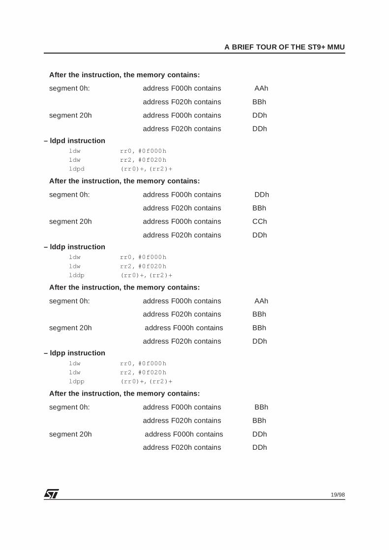
2.5.3 LDDD, LDPD, LDDP, LDPP instructions
The specific instructions use the same mechanism as previously described.
– LDDD: source and destination are accessed through the 2 DPRs selected
– LDPD: source is accessed using DPR and destination is accessed through CSR
– LDDP: source is accessed using CSR and destination is accessed through DPR
– LDPP: source is accessed using CSR and destination is accessed through CSR
For example
Whatever the sdm/spm status is before the following instructions, and assuming the same set-tings for CSR/DPRs as in the previous example.
Before the instruction the memory contains:
segment 0h: address F000h contains AAh
address F020h contains BBh
segment 20h address F000h contains CCh
address F020h contains DDh
– lddd instructionsldw rr0, #0f000h
ldw rr2, #0f020h
lddd (rr0)+,(rr2)+
19/98
A BRIEF TOUR OF THE ST9+ MMU
After the instruction, the memory contains:
segment 0h: address F000h contains AAh
address F020h contains BBh
segment 20h address F000h contains DDh
address F020h contains DDh
– ldpd instructionldw rr0, #0f000h
ldw rr2, #0f020h
ldpd (rr0)+,(rr2)+
After the instruction, the memory contains:
segment 0h: address F000h contains DDh
address F020h contains BBh
segment 20h address F000h contains CCh
address F020h contains DDh
– lddp instructionldw rr0, #0f000h
ldw rr2, #0f020h
lddp (rr0)+,(rr2)+
After the instruction, the memory contains:
segment 0h: address F000h contains AAh
address F020h contains BBh
segment 20h address F000h contains BBh
address F020h contains DDh
– ldpp instructionldw rr0, #0f000h
ldw rr2, #0f020h
ldpp (rr0)+,(rr2)+
After the instruction, the memory contains:
segment 0h: address F000h contains BBh
address F020h contains BBh
segment 20h address F000h contains DDh
address F020h contains DDh

20/98
A BRIEF TOUR OF THE ST9+ MMU
2.5.4 Interrupts and the Program/Data management
Depending on the memory model you choose when you compile and link the application, thecompiler will use sdm/spm instructions or not.
On ST9+, the only model available is with the -mpd option, which tells the compiler that pro-gram and data memories are distinct. In this configuration, the C compiler generates spm/sdminstructions only in the following cases:
– SWITCH statements: During the switch statement, the compiler sometimes needs to accesstables located in ROM (.text section). It thus needs to perform an SPM, then access the table,and return to the previous state by doing an SDM
– Interrupt service routines: An interrupt can occur at any time, and it is possible to enter aninterrupt service routine just after executing an spm instruction. So, the C compiler generatesan sdm instruction at the very beginning of a C interrupt service routine.
For the same reason, if an interrupt service routine is written in assembly it is strongly advisedto put an sdm at the very beginning of the interrupt routine.
Conclusion: It is strongly advised to place an sdm instruction at the very beginning of the pro-gram and never use the spm/sdm inside the program again, except for an interrupt serviceroutine written in assembler.
21/98
The V4.2 ST9+ GNU C Compiler
3 THE V4.2 ST9+ GNU C COMPILER
This section does not provide comprehensive information on the compiler. You are advised toread the ST9+ GNU C Toolchain Release 4.2 note. Most of the information in this section hasbeen directly extracted from this document and you will sometimes find more features docu-mented than those given here. Here we will only focus on the following points:
– ST9+ MCU only, not the ST9 compatibility
– New important options
– The different mappings allowed by the compiler
3.1 V4.2 GNU C COMPILER FEATURES AT A GLANCE
– Runs on Windows NT, Windows 95, Windows 3.x and DOS.
– ST9 and ST9+ compatible with different options.
– Only tiny and small data memory models available.
– Improved linker for managing MMU data pointers:The script file syntax supports new features for managing data and program memory blocks.
– Implementation of ST9+ new instructions.
– Set of assembly and C macros to facilitate MMU usage
– Optimization improvements
3.2 OPTIONS TO USE
In this part of the application note we will only consider the ST9+ MCU. Thus, only the impor-tant options will be described.
3.2.1 Compiler Options
-mfar: This option is used if more than 64 Kbytes of code are used in the application. It de-fines all functions as far, except static functions.
-mlink: This option will implement the prologue and epilogue of the C functions using thenew link/unlink instructions.
-mpd : This option, present on previous versions, specifies that a 2-memory model is used.It is a default option, and must be used on ST9+.
-tr9: This option is to include TR9 in the compilation. By default TR9 is no longer called whencompiling a C file, and this option is needed only if macro-assembly is used inside the appli-cation (C or Assembly files).
22/98
The V4.2 ST9+ GNU C Compiler
3.2.2 Linker Options
In this application note, the linker will always use a scriptfile. The only new and important op-tion is thus:
-mmu: This option allows relocation of the data object through the DPR registers. It is alsoneeded to have access to the MMU macros defined in C or Assembly.
3.3 HOW TO MANAGE THE MMU WITH THE COMPILER
The first thing you should do is evaluate which of the MMU memory models provided by theV4.2 Compiler is needed by your application.
3.3.1 MMU models handled by the V4.2 compiler
Two memory models can be handled by the compiler and linker:
– Total size of Code and Data is less than 64 Kbytes.=> in this case the MMU is fully transparent to the user
– Code size is more than 64 Kbytes and Data size is not taken into account:=> in this case the MMU Function management is fully handled by the compiler and the Datamanagement has to be done manually. However, the compiler provides features like reloca-tion of data objects and several macros to help manage the data.
3.3.2 Managing Functions
If the size of the application code and data does not exceed 64 Kbytes, there will be noproblem, so only applications that do not fulfil this condition have to be discussed here.
If the code size is greater than 64 Kbytes, then you have to use the -mfar option.
This option will set all functions far, except static functions. The proper libraries are automati-cally linked with the application.
Far function pointers are not supported by the V4.2 compiler. To allow pointing to functions lo-cated in different segments, some macros are implemented in the sources provided with thecompiler. The passing of parameters and return values is also available with the help ofmacros.
It should be noted that as macros are used, and because they don’t allow a variable numberof arguments, it is not possible to use far function pointers having a variable number of argu-ments.
In the following examples, it will be investigated in a first step the case where the code size insmaller than 64 Kbytes (ST92E195), no far functions will then be needed. In a second case,where the code size is larger than 64 Kbytes, and where all functions are far, examples offunction pointers will be implemented.
23/98
The V4.2 ST9+ GNU C Compiler
3.3.3 Managing Data
By default no DPR management is done. depending on the application, and especially if youuse more than 64 Kbytes of data you will have to manage the data pointers manually.
In this way, you can relocate a data object by defining, as a linker option, which data pointerwill be selected when accessing the data in C or Assembly.
For example:
If FOO is located at physical address 0x200200, its 16-bit address should be 0x0200, and thusonly DPR0 should be pointing to FOO.Then: ld R0, FOO<=> ld R0,0x0200 and DPR0 must be set to 0x80
We can tell the linker that FOO needs to be pointed to by DPR2 (for example), but keepingFOO at the same physical address. Then after relocation, the linker uses address 0x8200 (in-stead of 0x0200) to access FOO.
Then: ld R0, FOO<=> ld R0, 0x8200 and DPR2 contents must be 0x80
This relocation is very powerful as it allows you to have different blocks of data, pointed to bythe same DPR or group of DPRs, even if their physical addresses are completely different.Then it’s up to you to switch the DPR values depending on the data that is accessed.
Some macros are provided to allow you to retrieve and set the correct DPR value corre-sponding to particular data in a routine. These macros are:PAG (symbol) <= returns the physical page number
POF(symbol) <= returns the offset inside the 16Kbyte memory block (14 bits).
For example, before accessing variable Var, if it has been relocated with DPR3, it is possibleto do:DPR3 = PAG(Var);
Var = 0x12;
3.4 MAPPING YOUR APPLICATION WITH THE LINKER
In this application note, we advise you to define a scriptfile for each application. The scriptfileis a memory description file that allows you to fine tune the memory mapping. With the script-file, you can locate each section (.text, .data and .bss) of a selected file in a user-definedmemory region.
3.4.1 The possible data/code sections and their mapping
In ST9+, we consider as data, both the uninitialized variables (.bss section), the initialized var-iables (.data section) and the constants (.data section).
With the -mpd complier option, there is no difference for the compiler and the linker betweenconstants and initialized variables. They are both located in the .data section.
24/98
The V4.2 ST9+ GNU C Compiler
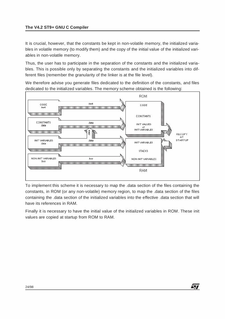
It is crucial, however, that the constants be kept in non-volatile memory, the initialized varia-bles in volatile memory (to modify them) and the copy of the initial value of the initialized vari-ables in non-volatile memory.
Thus, the user has to participate in the separation of the constants and the initialized varia-bles. This is possible only by separating the constants and the initialized variables into dif-ferent files (remember the granularity of the linker is at the file level).
We therefore advise you generate files dedicated to the definition of the constants, and filesdedicated to the initialized variables. The memory scheme obtained is the following:
To implement this scheme it is necessary to map the .data section of the files containing theconstants, in ROM (or any non-volatile) memory region, to map the .data section of the filescontaining the .data section of the initialized variables into the effective .data section that willhave its references in RAM.
Finally it is necessary to have the initial value of the initialized variables in ROM. These initvalues are copied at startup from ROM to RAM.
25/98
The V4.2 ST9+ GNU C Compiler
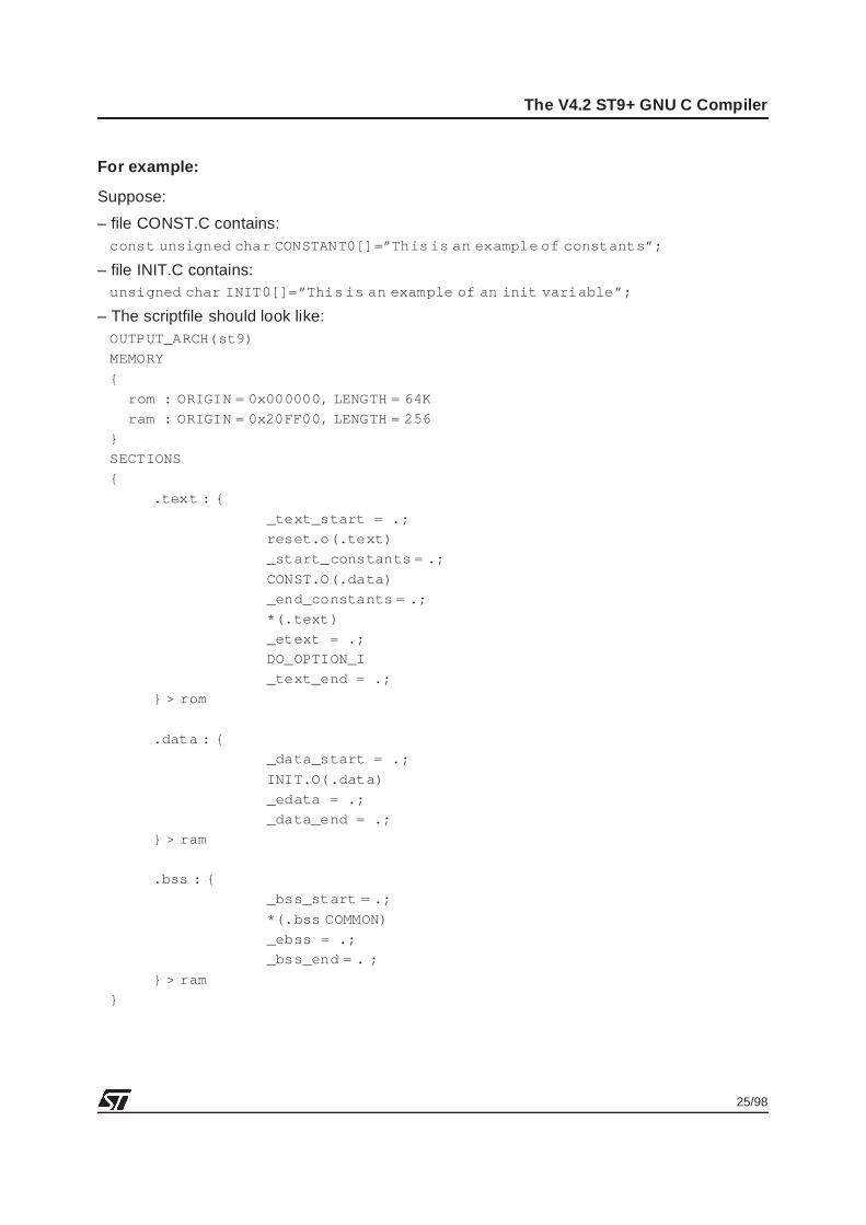
For example:
Suppose:
– file CONST.C contains:const unsigned char CONSTANT0[]=”This is an example of constants”;
– file INIT.C contains:unsigned char INIT0[]=”This is an example of an init variable”;
– The scriptfile should look like:OUTPUT_ARCH(st9)
MEMORY
{
rom : ORIGIN = 0x000000, LENGTH = 64K
ram : ORIGIN = 0x20FF00, LENGTH = 256
}
SECTIONS
{
.text : {
_text_start = .;
reset.o(.text)
_start_constants = .;
CONST.O(.data)
_end_constants = .;
*(.text)
_etext = .;
DO_OPTION_I
_text_end = .;
} > rom
.data : {
_data_start = .;
INIT.O(.data)
_edata = .;
_data_end = .;
} > ram
.bss : {
_bss_start = .;
*(.bss COMMON)
_ebss = .;
_bss_end = . ;
} > ram
}
26/98
The V4.2 ST9+ GNU C Compiler
3.4.2 Notes on using Initialized Variables
One limitation of the linker is that it is not possible to have more than 64 Kbytes of initializedvariables in one application. This is due to the fact that the .data section of the linker cannotexceed 64 Kbytes.
Anyway, it is advised not to use any initialized variables, but to use non-initialized variablesthat are initialized inside a specific routine.
Also, even if there are no initialized variables in an application, you are advised to separate theconstants and variables into dedicated files. This is not a real restriction, and it promotes de-velopment of clean and maintainable software.
Anonymous strings are also a problem in the compiler, because they are mapped in the .textsection, but still need to be pointed to by a DPR.
To avoid this, for example, instead of:void func()
{
printf(”Hello world”);
}
It is advised to do:
const unsigned char foo[] =”Hello world”;
unsigned char *pfoo;
void func()
{
pfoo = foo;
printf(pfoo);
}
Refer also to the LD9 linker Documentation for complete information on scriptfile syntax andcapabilities.
In the examples given in detail below, the mapping of the DATA in the script file will be dis-cussed case by case, as various possibilities are available to the user.
Let us look now at the possibility of relocating the data objects so they can be pointed to by de-fined DPRs.
The principle is the following:
If a data Var is to be mapped physically at address 0x200000, it seems obvious that if nothingis done, the logical address of Var is 0x0000. Consequently, Var must use DPR0 to generatethe physical address.
27/98
The V4.2 ST9+ GNU C Compiler
Suppose that for different reasons, DPR0 needs to point to the 16 Kbyte segment starting ataddress 0x220000, and that no modification of the value of DPR0 is possible (for exampleDPR0 points to the stack location).
In this case you need to point to the Var variable with another DPR. This is then implementedin the scriptfile by specifying which DPR points to a particular memory block.
For example, suppose we have originally:RAM1: ORIGIN = 0x200000, LENGTH = 16K
with the linker of the V4.2 chain, it is possible to specify:RAM1: ORIGIN = 0x200000, LENGTH = 16K, MMU = DPR2
In this case all data are relocated from 0x0000 to 0x3FFF to 0x8000 to 0xCFFF, and conse-quently the physical addresses will be generated with the DPR2 value.
This means that whatever the physical address of a data object, it can use any of the DPR reg-isters.
The general syntax for the scriptfile is:NAME: ORIGIN = 22-bit address, LENGTH = xx, MMU = DPR list
where DPR list can be any one of the following:DPR0, DPR1, DPR2, DPR3, CSR, NO
– If NO is specified, then no relocation is done. If data is found in the segment, and a referenceto this data is made, a warning is generated to tell the user that some data are present in thisregion, without a specific DPR coverage.
– If CSR is specified, nothing is done (no relocation, no warning). This option is useful if a seg-ment contains only code.
– If DPRx is specified, relocation of the 16 Kbytes block is based on DPRx.
Warning: Although it is possible to relocate data with the same DPR, inside a 64K segment,you will still have to set the specific DPR to the correct value before accessing the data.
To avoid programming errors, you are advised to define blocks of data with the same size asthe area that can be covered by the total number of free DPRs. That is, for example, if DPR0and DPR1 are free to access data, then you can define blocks of 32K covered by DPR0 andDPR1 only.
Note: Relocation with DPR registers is done only on .data and .bss sections. You should beaware that if some constants are defined in assembly using for example:.text
TAB1:
.byte 0xAA
28/98
The V4.2 ST9+ GNU C Compiler
then TAB1 will not be relocated with specific DPRs because it is located in the .text section. Inassembly, to allow relocation the following notation should be used:
.data
TAB1:
.byte 0xAA
and of course, this constant should still be located in a separate file and follow the same map-ping scheme as described previously.
3.4.3 A tentative set of general rules
It is difficult to follow general rules for managing the data pointers within an application. It fullydepends on the memory mapping of the MCU used, and on the requirements of the memoryapplication.
An application will always use:
– A stack: kept in RAM
– Non-initialized variables, kept in RAM
– Constants and initial values of initialized variables, mapped in ROM
– Code, located in ROM:
One DPR must be fixed, to always point to the system and user stacks. This is especially truefor applications written in C, as most parameters, local variables and return values are ac-cessed through the system or user stacks. In general the stacks don’t take more than 16Kbytes of memory, so only one pointer needs to be fixed.
For most applications, 16 Kbytes of RAM is enough, thus only one DPR can be used to accessthe non-initialized variables and the stacks.The 3 other free DPRs, can be either kept grouped together, which allow to treat data memoryblocks of 3x16 = 48 Kbytes. This case is suitable for large applications having a small amountof RAM and very large ROM needs.If large amounts of RAM are needed, this often means that large data memory transfers areperformed, and in this case, one DPR will be used to point to the source, another one to pointto the destination of the transfer. The third is free for other resources.
If a different memory exists, located in a different region from the RAM, for example the 8Kbytes TDSRAM of the ST92E195, one pointer can be dedicated to this memory and the 2 re-maining pointers used for accessing constants.
Anyway, the DPR allocation needs to be done case by case, and the current V4.2 compilerdoes not provide an easy and transparent way of doing data management, so it up to the soft-ware programmer to define a DPR allocation strategy that best suits the application needs.The examples described below try to cover the most frequent memory situations that canarise.
29/98
The V4.2 ST9+ GNU C Compiler
3.5 SUMMARY OF V4.2 ST9+ GNU C COMPILER LIMITATIONS
– No automatic and transparent data management
– In the large code model, no automatic and transparent function pointer, with the possibilityof using macros instead
– No variable number of arguments in pointers to far functions.
– Constants must be separated from the code and the initialized variables
All these limitations should be removed in the next ST9+ compiler generation.
30/98
First example: The ST92195
4 FIRST EXAMPLE: THE ST92195
The ST92195 is an MCU dedicated to TV applications. It is however very interesting for dem-onstrating the MMU usage because of its specific memory mapping, with 3 different on-chipmemories, the ROM, RAM and TDSRAM.
The example will demonstrate a small OSD (On Screen Display) application showing a pos-sible and recommended way of using the MMU with the C compiler V4.2, with such a memoryconfiguration.
4.1 MEMORY MAPPING
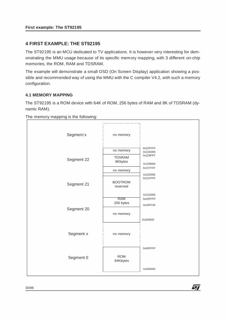
The ST92195 is a ROM device with 64K of ROM, 256 bytes of RAM and 8K of TDSRAM (dy-namic RAM).
The memory mapping is the following:
no memory
TDSRAM8Kbytes
BOOTROMreserved
RAM256 bytes
no memory
no memory
no memory
ROM64Kbytes
Segment x
Segment 0
Segment 20
Segment 21
Segment 22
Segment x
0x000000
0x00FFFF
0x200000
0x20FF00
0x20FFFF
0x210000
0x21FFFF0x220000
0x227FFF
0x228000
0x229FFF0x22A0000x22FFFF
no memory
31/98
First example: The ST92195
4.2 DESCRIPTION OF THE APPLICATION
The application proposed will display on 3 lines of OSD, representing an OSD Menu. Thenusing an automaton table, specific events will select the different rows of the menu, or will es-cape/enter into the menu.
This type of automaton management is a simple way of navigating in menus, and could be ap-plied to any application.
To simplify the examples, 5 events where created, representing a user pressing either a keyUP, or DOWN, or ESCAPE, or SET_MENU. To avoid having to create a keyboard driver, aroutine generates random events in a periodic manner.
What the example would like to highlight is:
– Managing the 3 different memories: how to select the correct MMU settings
– Constants: how to map and use them
– Initialized variables: how to map and use them
The application will physically display the menu on a TV screen if the user has a ST92195 De-moboard, or any board able to display the ST92195 OSD signals.
4.3 MMU SETTINGS ON THE ST92195
The memory mapping of the ST92195 shows 3 different memory types, firstly the ROM wherethe code, constants, and initial values for the initialized variables should be located, secondlythe RAM needed for the variables (initialized or uninitialized) and the stack and thirdly, the TD-SRAM used for the OSD display.
The ROM contains only 64 Kbytes, so no far calls will be needed, which means that workingwith functions is completely transparent.
The stack and variables are in segment 20h, page 83h. As this memory needs to be accessedat any time there must be a pointer set permanently to this location. DPR3 will thus be as-signed to point to the RAM.
The TDSRAM must be accessed for transferring display variables, the characters and at-tributes necessary for the OSD. Its location is segment 22h, page 8Ah. As this memory mayalso contain teletext data, whose flow is independent of the program flow, it is important to al-ways have a fixed pointer to this memory. DPR2 will be this pointer.
For the constants, located in the ROM, it is necessary to be more careful. Only 2 DPRs are leftfree to access these constants, so 2 choices are possible depending on how many constantsare present in the application:
– Less than 32 Kbytes of constants are present:=>In this case, it will be sufficient to set the DPRs to two 16 Kbyte contiguous pages, and to
32/98
First example: The ST92195
never modify the DPRs during the program execution. For example, it is possible to map allthe constants starting from 0x000000 to 0x007FFFF, then set DPR0 = 0x00 and DPR1 =0x01.
– More than 32 Kbytes of constants are needed by the application:=> In this case, the DPRs will need to be modified. This will have to be done explicitly in thecode when necessary. It will also be necessary to split the 64 Kbytes segment 0 into two32 Kbyte blocks because of the risk of a data overlapping page 0x01 and 0x02.
In our example, only the first case will be developed further.
The expected MMU settings will be the following:
Warning: There is only one region with no DPR coverage, the region 0x008000 to 0x00FFFF.It is important to understand this can be a problem ONLY if any data are accessed in this re-gion. The scriptfile can avoid this problem, by defining which regions are uncovered in order togenerate a Warning during the link phase.
33/98
First example: The ST92195
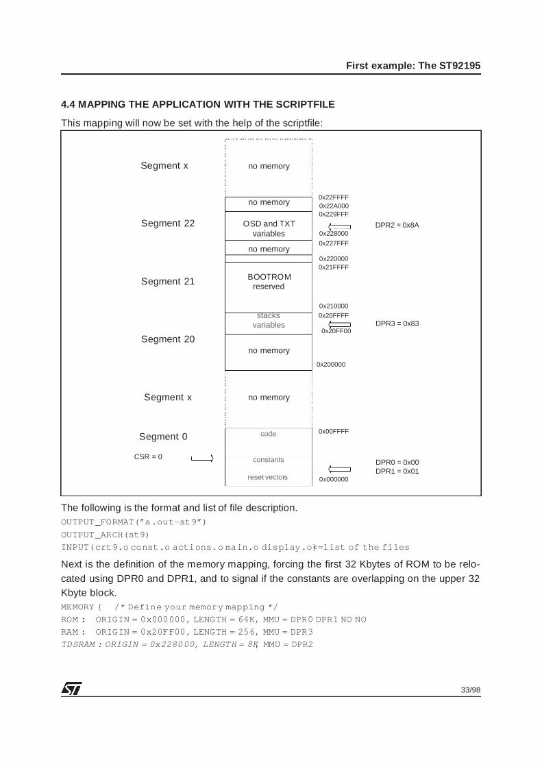
4.4 MAPPING THE APPLICATION WITH THE SCRIPTFILE
This mapping will now be set with the help of the scriptfile:
The following is the format and list of file description.OUTPUT_FORMAT(”a .out-st9”)
OUTPUT_ARCH(st9)
INPUT(crt9.o const.o actions.o main.o display.o) <=list of the files
Next is the definition of the memory mapping, forcing the first 32 Kbytes of ROM to be relo-cated using DPR0 and DPR1, and to signal if the constants are overlapping on the upper 32Kbyte block.MEMORY { /* Define your memory mapping */
ROM : ORIGIN = 0x000000, LENGTH = 64K, MMU = DPR0 DPR1 NO NO
RAM : ORIGIN = 0x20FF00, LENGTH = 256, MMU = DPR3
TDSRAM : ORIGIN = 0x228000, LENGTH = 8K, MMU = DPR2
no memory
OSD and TXTvariables
BOOTROMreserved
stacksvariables
no memory
no memory
no memory
code
constants
reset vectors
Segment x
Segment 0
Segment 20
Segment 21
Segment 22
Segment x
0x000000
0x00FFFF
0x200000
0x20FF00
0x20FFFF
0x210000
0x21FFFF0x220000
0x227FFF
0x228000
0x229FFF0x22A0000x22FFFF
no memory
DPR0 = 0x00DPR1 = 0x01
DPR3 = 0x83
DPR2 = 0x8A
CSR = 0
34/98
First example: The ST92195
Then the .data, .text and .bss sections are defined:SECTIONS {
_stack_size = DEFINED(_stack_size) ? _stack_size : 40;
_user_stack_size = DEFINED(_user_stack_size)? _user_stack_size : 40;
Important: The .text section is defined here. It should be noted that the CRT9.O object filecontains the reset and interrupt vectors, so this file should be mapped starting at 0x000000.
Then just after the crt9 file, the files containing the constants are mapped. Note that only the.data section of these files is taken, and mapped in a .text section. This is a trick to force thelinker to put the constants in ROM.
The DO_OPTION_I is an option that places the initial values of the initialized variables and theend of the .text section in ROM. The crt9 file does the recopy of these values to the variablesat startup.
.text : {
_text_start = .;
crt9.o(.text)
const.o(.data)
*(.text)
_etext = .;
DO_OPTION_I;
_text_end = .;
} >ROM
As all the constants are now mapped in .text section, mapping the .data section of all otherfiles will then set only the initialized variables in .data.
.data :{
_data_start = .;
*(.data)
_data_end = .;
} >RAM
The .bss section will then contain the stacks and the non initialized variables.
35/98
First example: The ST92195
Note also that both the .data section and the .bss section are located in RAM.
.bss : {
_bss_start = .;
*(.bss COMMON)
_ebss =.;
_bss_end = .;
_stack_start = DEFINED(_stack_start)?
_stack_start : .;
_stack_end = _stack_start + _stack_size;
_user_stack_start = DEFINED(_user_stack_start)?
_user_stack_start : _stack_end;
_user_stack_end = _user_stack_start + _user_stack_size;
} >RAM
}
Important: In this example, no variables were allocated to the TDSRAM. It could have beenpossible to put both .data or .bss (init or non-init variables) in this memory. However becausethe TDSRAM is managed in a special way, you should refer to the ST92195 Datasheet for in-formation on how to use it.
Following are the block diagrams obtained for the ROM and the RAM, according to this map-ping.
36/98
First example: The ST92195
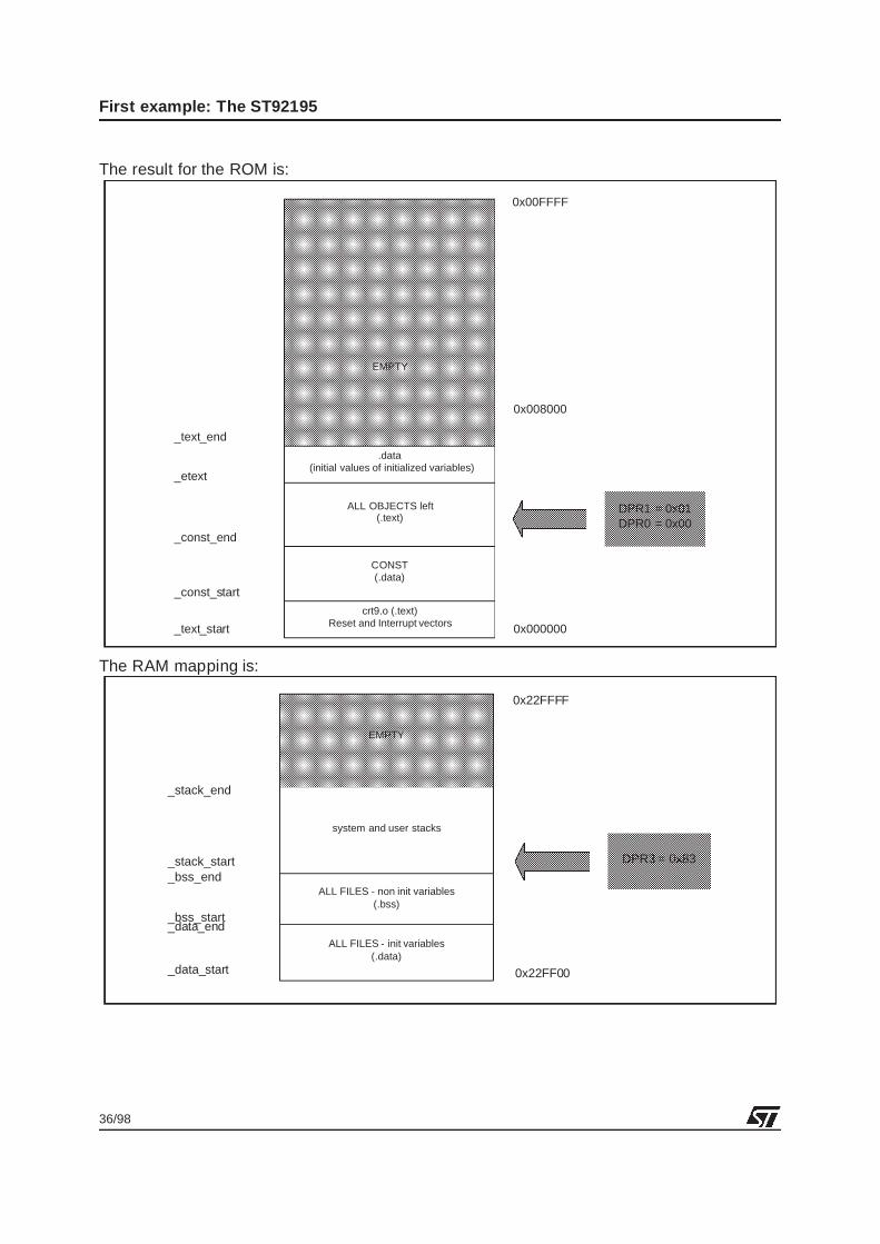
The result for the ROM is:
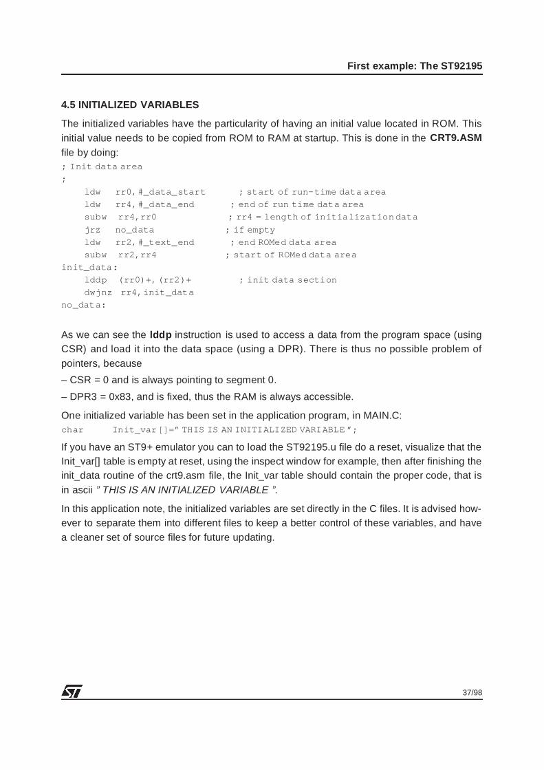
The RAM mapping is:
EMPTY
0x000000
0x00FFFF
crt9.o (.text)Reset and Interrupt vectors
CONST(.data)
ALL OBJECTS left(.text)
.data(initial values of initialized variables)
_text_start
_text_end
_etext
_const_start
_const_end
0x008000
DPR1 = 0x01DPR0 = 0x00
EMPTY
0x22FF00
ALL FILES - non init variables(.bss)
ALL FILES - init variables(.data)
system and user stacks
_bss_start
_stack_end
_stack_start_bss_end
DPR3 = 0x83
_data_start
_data_end
0x22FFFF
37/98
First example: The ST92195
4.5 INITIALIZED VARIABLES
The initialized variables have the particularity of having an initial value located in ROM. Thisinitial value needs to be copied from ROM to RAM at startup. This is done in the CRT9.ASMfile by doing:; Init data area
;
ldw rr0,#_data_start ; start of run-time data area
ldw rr4,#_data_end ; end of run time data area
subw rr4,rr0 ; rr4 = length of initialization data
jrz no_data ; if empty
ldw rr2,#_text_end ; end ROMed data area
subw rr2,rr4 ; start of ROMed data area
init_data:
lddp (rr0)+, (rr2)+ ; init data section
dwjnz rr4,init_data
no_data:
As we can see the lddp instruction is used to access a data from the program space (usingCSR) and load it into the data space (using a DPR). There is thus no possible problem ofpointers, because
– CSR = 0 and is always pointing to segment 0.
– DPR3 = 0x83, and is fixed, thus the RAM is always accessible.
One initialized variable has been set in the application program, in MAIN.C:char Init_var []=” THIS IS AN INITIALIZED VARIABLE ”;
If you have an ST9+ emulator you can to load the ST92195.u file do a reset, visualize that theInit_var[] table is empty at reset, using the inspect window for example, then after finishing theinit_data routine of the crt9.asm file, the Init_var table should contain the proper code, that isin ascii ” THIS IS AN INITIALIZED VARIABLE ”.
In this application note, the initialized variables are set directly in the C files. It is advised how-ever to separate them into different files to keep a better control of these variables, and havea cleaner set of source files for future updating.
38/98
First example: The ST92195
4.6 COMPILER AND LINKER OPTIONS
The options used in the application for compiling are:
-mlink : Use ST9+ link/unlink instructions
-g: Generate debug information
-O: Use the optimizer
-fomit-frame-pointer : Avoid usage of frame pointer when not needed
-Wall : Get all possible warnings
-tr9 : Use tr9
-Wall,-ahld : Generate a list file
The linker options are:
-mmu : Allow relocation with DPRs
-m: Generate a map file
-T: Use a scriptfile
-v: Set verbose mode on
4.7 APPLICATION FILES
The necessary application files:
– MAKEFILE The file needed to make the application
– MAKEDEP The dependency description file
– MAIN.C Contains the main routine
– CONST.C Contains the CONSTANTS definition
– ACTION.C Contains the various automaton routines
– DISPLAY.C Contains the OSD routines
– CRT9.ASM The startup file, contains the interrupt vectors, and calls mainit also initializes the ST9+ correctly
– ST92195.SCR The scriptfile, contains the memory mapping description
– ST92195.U The executable needed by the debugger
– ST92195.HEX The hexadecimal file needed to program EPROM/OTPs
In addition, all header files and some ST9 macros are used and defined in:ST9MACRO.H, NEWREG.H, DEFINE.H, DISPLAY.H,OSD_CONS.H
39/98
First example: The ST92195
4.8 EMULATOR CONFIGURATION FILE
To configure the memory used on the ST92195 emulator Version HDS2, the user must usethe file HARDWARE.GDB provided with the application. This file contains:
clear_map
map 0x000000 0xFFFF SR
map 0x20FC00 0xFFFF SW
map 0x228000 0x9FFF SW
chip_reset

40/98
Second example: the ST92R195
5 SECOND EXAMPLE: THE ST92R195
The ST92R195 is a ROMless device, capable of accessing up to 4Mbytes of memory, througha 16-bit + 6-bit address bus.
The ST92R195 is dedicated to TV applications and has the same peripherals as the ST92195.It is mainly intended for accessing a large external ROM and only the 512 bytes on-chip RAM.No additional RAM should be used. It also contain 8 Kbytes of on-chip TDSRAM for OSD dis-play and teletext data storage.
5.1 ST92R195 MEMORY MAPPING
no memory
TDSRAM8Kbytes
BOOTROMreserved
RAM512 bytes
no memory
no memory
no memory
no memory
from segment 1 to 19h
Segment 0
Segment 20
Segment 21
Segment 22
from segment 23h to 39h
0x000000
0x00FFFF
0x200000
0x20FD00
0x20FFFF
0x210000
0x21FFFF0x220000
0x227FFF
0x228000
0x229FFF0x22A0000x22FFFF
no memory
Externalmemory
Externalmemory
Externalmemory
reserved to internalmemory
Internal Memory External Memory
41/98
Second example: the ST92R195
Three 64 Kbyte blocks are internal:
– Segment 20h: Contains the internal RAM from 0x20FFD0 to 0x20FFFF
– Segment 21h: Contains the bootrom, and is reserved for test purposes
– Segment 22h: Contains the TDSRAM from 0x228000 to 0x229FFF
These 3 segments are fully internal, only the internal memory in segment is accessible to theuser. It is thus not possible, for example to use external memory in segment 20h.
As only external ROM is used, it is clear that both functions and data will require the MMU.
5.2 APPLICATION DESCRIPTION
The application displays an OSD menu, split into 3 different segments, using an automaton.The events that will successively call the display of the menu management are random, toavoid implementing a user interface.
This will involve the following topics in detail:
– Far Function management (the functions that call the menus are all far)
– Static Function management
– Data pointer management (as the Menu lines are located in different blocks)
– Memory mapping for large applications
5.3 MANAGING FUNCTIONS
With an application containing more than 64 Kbytes of code, and with the V4.2 C Compiler, itis only possible to use the Large memory model, which defines all functions as far.
Static functions are automatically called with call and returned with ret . This is normal, asstatic functions are not called outside of the file where they are defined, and the mapping of afile can not overlap 2 segments, they are thus always called from routines located in samesegment.
Note : When declaring a static function, do not forget to declare the prototype of the static func-tion as well, if the function is called before its definition. Otherwise an error message will begenerated during the link.
If you want to make reference to external functions, defined in an assembly file, these func-tions must be ended with rets and must always be called in the assembly with calls .
Note : With the calls instruction the code size increases by 1 byte for each call, and the stackis also increased by 1 byte (for stacking CSR).
42/98
Second example: the ST92R195
5.3.1 Using function pointers
Function pointers are not supported by the compiler version V4.2, they will be supported onlyin the future versions.
To workaround this limitation, a solution is to use a structure made of a char and a pointer toa function, then to use a macro for doing the far call to the function. A possible macro is pro-vided in the mmu.h file.
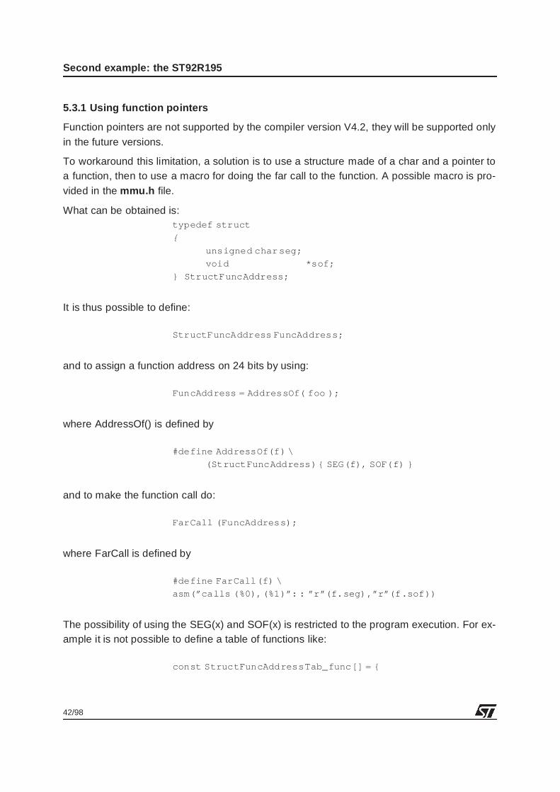
What can be obtained is:typedef struct
{
unsigned char seg;
void *sof;
} StructFuncAddress;
It is thus possible to define:
StructFuncAddress FuncAddress;
and to assign a function address on 24 bits by using:
FuncAddress = AddressOf( foo );
where AddressOf() is defined by
#define AddressOf(f) \
(StructFuncAddress) { SEG(f), SOF(f) }
and to make the function call do:
FarCall (FuncAddress);
where FarCall is defined by
#define FarCall(f) \
asm(”calls (%0),(%1)”: : ”r”(f.seg),”r”(f .sof))
The possibility of using the SEG(x) and SOF(x) is restricted to the program execution. For ex-ample it is not possible to define a table of functions like:
const StructFuncAddressTab_func[] = {
43/98
Second example: the ST92R195
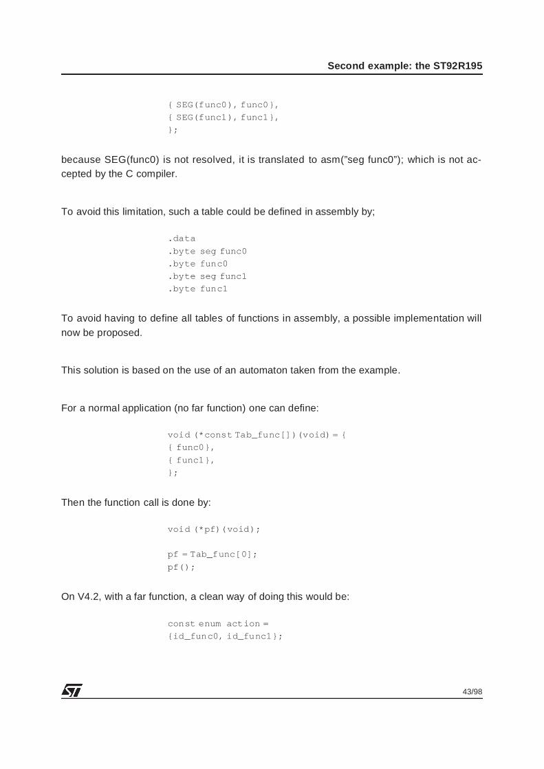
{ SEG(func0), func0},
{ SEG(func1), func1},
};
because SEG(func0) is not resolved, it is translated to asm(”seg func0”); which is not ac-cepted by the C compiler.
To avoid this limitation, such a table could be defined in assembly by;
.data
.byte seg func0
.byte func0
.byte seg func1
.byte func1
To avoid having to define all tables of functions in assembly, a possible implementation willnow be proposed.
This solution is based on the use of an automaton taken from the example.
For a normal application (no far function) one can define:
void (*const Tab_func[])(void) = {
{ func0},
{ func1},
};
Then the function call is done by:
void (*pf)(void);
pf = Tab_func[0];
pf();
On V4.2, with a far function, a clean way of doing this would be:
const enum action =
{id_func0, id_func1};
44/98
Second example: the ST92R195
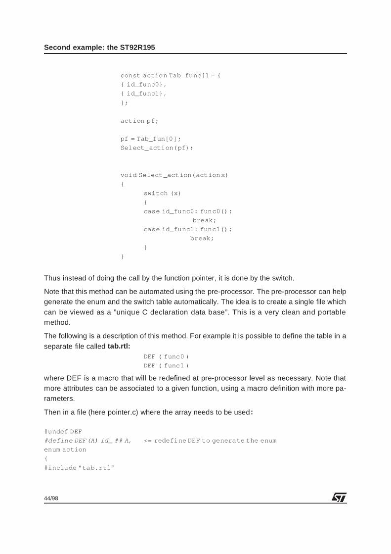
const action Tab_func[] = {
{ id_func0},
{ id_func1},
};
action pf;
pf = Tab_fun[0];
Select_action(pf);
void Select_action(action x)
{
switch (x)
{
case id_func0: func0();
break;
case id_func1: func1();
break;
}
}
Thus instead of doing the call by the function pointer, it is done by the switch.
Note that this method can be automated using the pre-processor. The pre-processor can helpgenerate the enum and the switch table automatically. The idea is to create a single file whichcan be viewed as a ”unique C declaration data base”. This is a very clean and portablemethod.
The following is a description of this method. For example it is possible to define the table in aseparate file called tab.rtl:
DEF ( func0 )
DEF ( func1 )
where DEF is a macro that will be redefined at pre-processor level as necessary. Note thatmore attributes can be associated to a given function, using a macro definition with more pa-rameters.
Then in a file (here pointer.c) where the array needs to be used :
#undef DEF
#define DEF(A) id_ ## A, <= redefine DEF to generate the enum
enum action
{
#include ”tab.rtl”
45/98
Second example: the ST92R195
};
#undef DEF
#define DEF(A) { id_ ## A }, <= redefine DEF to generate the array
const enum action Tab_func[] =
{
#include ”tab.rtl”
};
#undef DEF
#define DEF(A) {void A(void)), <= redefine DEF to generate prototypes
#include ”tab.rtl”
void Select_action(enumaction);
void main(void)
{
enum action pf;
pf = Tab_func[0]; <= select the function to execute
Select_action(pf);
}
void Select_action(enumaction x)
{
switch (x) <= treat the function to execute according
{ to array.
#undef DEF
#define DEF(A) case id_ ## A: A(); break;
#include ”tab.rtl”
default: fatal();
}
}
void func0(void)
{return;}
void func1(void)
{return;}
The code generated by the C pre-processor is:# 1 ”pointer.c”
enum action
{
# 1 ”tab.rtl” 1

46/98
Second example: the ST92R195
id_func0,
id_func1,
# 5 ”pointer.c” 2
};
const enum action Tab_func[] =
{
# 1 ”tab.rtl” 1
{ id_func0 },
{ id_func1 },
# 12 ”pointer.c” 2
};
void func0(void);
void func1(void);
void Select_action(enumaction);
void main(void)
{
enum action pf;
pf = Tab_func[0];
Select_action(pf);
}
void Select_action(enumaction x)
{
switch (x)
{
# 1 ”tab.rtl” 1
case id_func0: func0(); break;
case id_func1: func1(); break;
# 32 ”pointer.c” 2
default: fatal();
}
}
void func0(void)
{return;}
void func1(void)
{return;}
Of course, this can be applied to a more complete table containing several elements, not justthe pointer.
47/98
Second example: the ST92R195
5.4 MANAGING DATA
There is no automatic management of DPRs in the V4.2 compiler. The DPR positioning is leftup to the user.
Taking the example of the ST92R195 we have:
– DPR3 can be fixed to point to the RAM page (page 83h) for stack and variable accesses inRAM
– DPR2 can be fixed to point to the TDSRAM page (page 8Ah) for OSD and Teletext variables
– DPR0 and DPR1 are free for managing the constants in various pages of ROM
DPR3 and DPR2 will never be modified during program execution. Thus, the initialization oftheir value will only be done once.
For DPR0 and DPR1 two solutions are possible:
– Group DPR0-1 and have access to two contiguous 16 Kbyte pagesThis case is advantageous because the granularity of the memory is 32K, and data transfersare supposed to be done from ROM to RAM or TDSRAM only.
– Use DPR0 and DPR1 separatelyIn this case, it will be necessary to map all the constants by blocks of 16 Kbytes only. Theadvantage is you can scan a graph in ROM for example, and access data in ROM in anothersegment, at the same time.
The second case is not recommended for the ST92R195, because it makes using the DPRsmore difficult and may generate software errors. It would limit the maximum data size to 16Kbytes. Code maintainability may also be more difficult.
In the ST92R195, memory usage is as follows:
– RAM: less than 16 Kbytes (512bytes)., thus only one DPR can be used, it is fixed.
– TDSRAM: less than 16 Kbytes (8 Kbytes), thus only one DPR can be used, it is fixed.
– ROM More than 64 Kbytes will be used, two DPRs are left free for the ROM, their contentscan be modified depending on the ROM accessing requirements.
Note also that transfers should occur only either from ROM to RAM, from ROM to TDSRAM,or in either direction between RAM and TDSRAM.
The proposed scheme is to group DPR0 and DPR1. Thus, the granularity will be 32 Kbytes forthe data. Then, all data transfer (as described above) can be easily implemented just by mod-ifying the DPR0 and DPR1 as needed.
This scheme will be implemented in the example.
The application example presented here shows access to data located in 4 different seg-ments, 0, 1, 2 and 3.
48/98
Second example: the ST92R195
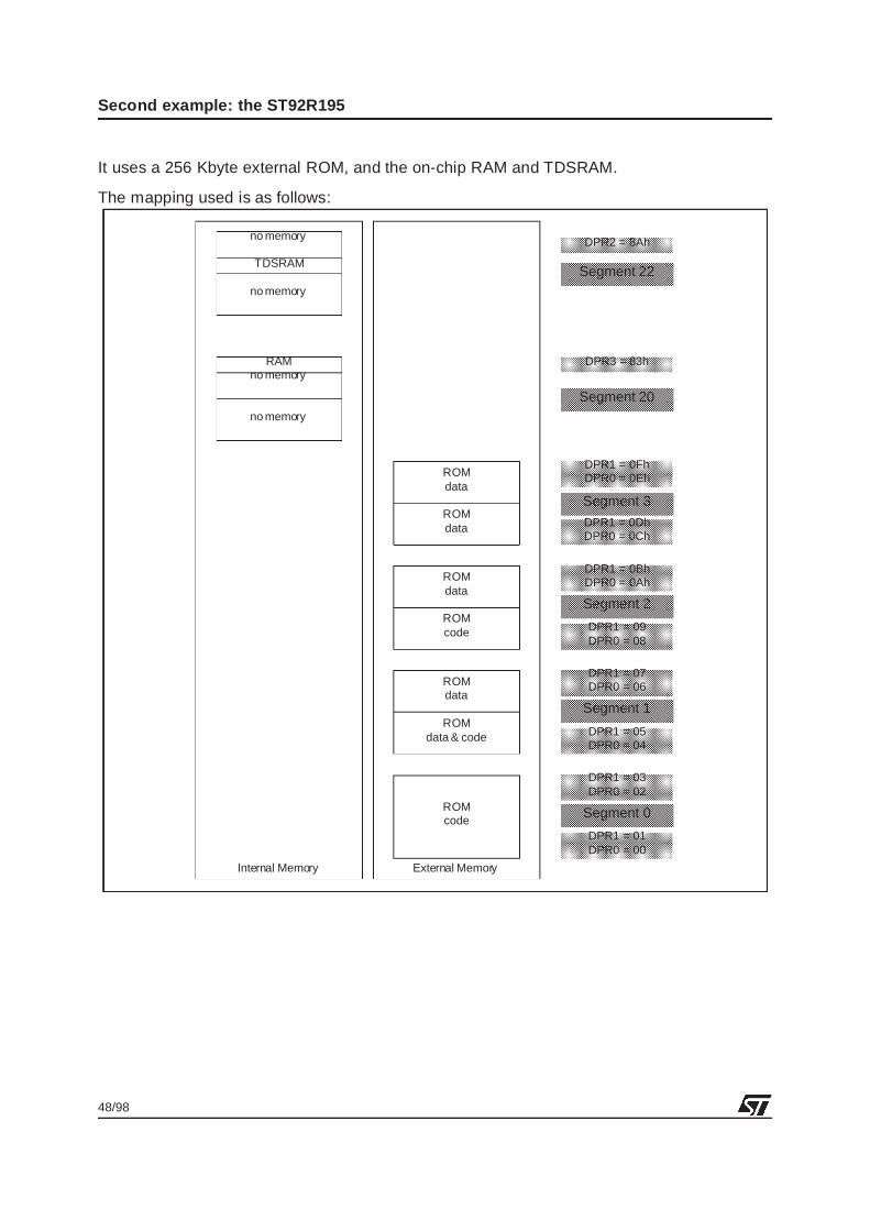
It uses a 256 Kbyte external ROM, and the on-chip RAM and TDSRAM.
The mapping used is as follows:
Internal Memory External Memory
RAMno memory
no memory
ROMdata
no memory
TDSRAM
no memory
ROMcode
ROMdata
ROMdata & code
ROMdata
ROMdata
ROMcode
Segment 0
Segment 1
Segment 2
Segment 3
Segment 20
Segment 22
DPR1 = 05DPR0 = 04
DPR1 = 01DPR0 = 00
DPR1 = 03DPR0 = 02
DPR1 = 07DPR0 = 06
DPR1 = 09DPR0 = 08
DPR1 = 0BhDPR0 = 0Ah
DPR1 = 0DhDPR0 = 0Ch
DPR1 = 0FhDPR0 = 0Eh
DPR3 = 83h
DPR2 = 8Ah
49/98
Second example: the ST92R195
5.4.1 C and Assembly directives for managing the data
The assembler provides directives for accessing the page and offset of a specific data.
For example, if Var is located at address 0x20FF00 then:ld DPR0, #pag Var
ld R2, #pof Var <= #pof Var is a 14-bit address.
will load DPR0 with 0x83 (page 3 of segment 0x20) and R2 with the contents of Var from ad-dress 0x20FF00.
The same thing is available in C, but using macros that refer to the pag & pof of the assem-bler. This is:PAG(Var);
POF(Var);
The result will be the same.
It must be understood that arrays of constants cannot be defined in C with these macros.
In the same way as for functions, they can be defined in assembly.
Note also that if relocation is used, the POF macro is unnecessary because the offset of therelocated variable will always correspond to the correct DPR access.
5.4.2 Managing the data pointer changes
The ideal would to minimize the DPR modifications.
A very clean way of programming with the constraint of the DPRs would be, for functions thatneed to call far variables, to pass the DPR contents as a parameter of the function itself.
For example:typedef struct fardata
{
unsigned char dpr;
unsigned char *var; <= or even better: void * var;
};
unsigned char STRING1[] = ”This is an example of constant data”;
void main()
{
fardata Var1 ;
...
Var1.dpr = PAG(STRING1);
Var1.var = STRING1;
function_x(Var1)
...
}
50/98
Second example: the ST92R195
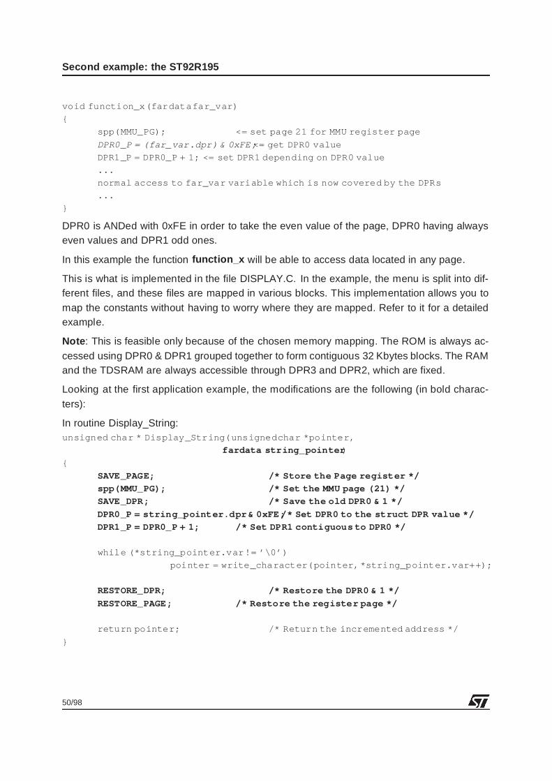
void function_x(fardatafar_var)
{
spp(MMU_PG); <= set page 21 for MMU register page
DPR0_P = (far_var.dpr) & 0xFE; <= get DPR0 value
DPR1_P = DPR0_P + 1; <= set DPR1 depending on DPR0 value
...
normal access to far_var variable which is now covered by the DPRs
...
}
DPR0 is ANDed with 0xFE in order to take the even value of the page, DPR0 having alwayseven values and DPR1 odd ones.
In this example the function function_x will be able to access data located in any page.
This is what is implemented in the file DISPLAY.C. In the example, the menu is split into dif-ferent files, and these files are mapped in various blocks. This implementation allows you tomap the constants without having to worry where they are mapped. Refer to it for a detailedexample.
Note : This is feasible only because of the chosen memory mapping. The ROM is always ac-cessed using DPR0 & DPR1 grouped together to form contiguous 32 Kbytes blocks. The RAMand the TDSRAM are always accessible through DPR3 and DPR2, which are fixed.
Looking at the first application example, the modifications are the following (in bold charac-ters):
In routine Display_String:unsigned char * Display_String(unsignedchar *pointer,
fardata string_pointer )
{
SAVE_PAGE; /* Store the Page register */
spp(MMU_PG); /* Set the MMU page (21) */
SAVE_DPR; /* Save the old DPR0 & 1 */
DPR0_P = string_pointer.dpr& 0xFE; /* Set DPR0 to the struct DPR value */
DPR1_P = DPR0_P + 1; /* Set DPR1 contiguous to DPR0 */
while (*string_pointer.var != ’\0’)
pointer = write_character(pointer, *string_pointer.var++);
RESTORE_DPR; /* Restore the DPR0 & 1 */
RESTORE_PAGE; /* Restore the register page */
return pointer; /* Return the incremented address */
}
51/98
Second example: the ST92R195
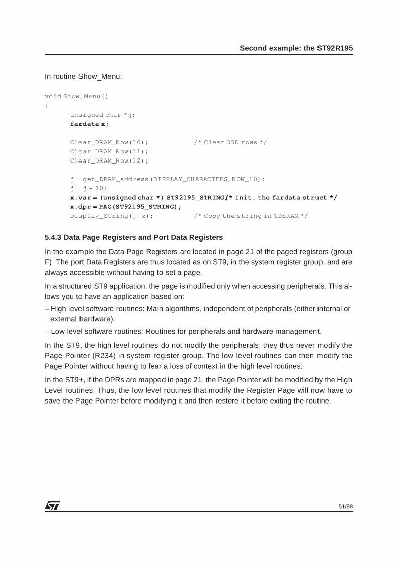
In routine Show_Menu:
void Show_Menu()
{
unsigned char *j;
fardata x;
Clear_DRAM_Row(10); /* Clear OSD rows */
Clear_DRAM_Row(11);
Clear_DRAM_Row(12);
j = get_DRAM_address(DISPLAY_CHARACTERS,ROW_10);
j = j + 10;
x.var = (unsigned char *) ST92195_STRING; /* Init. the fardata struct */
x.dpr = PAG(ST92195_STRING);
Display_String(j, x); /* Copy the string in TDSRAM */
5.4.3 Data Page Registers and Port Data Registers
In the example the Data Page Registers are located in page 21 of the paged registers (groupF). The port Data Registers are thus located as on ST9, in the system register group, and arealways accessible without having to set a page.
In a structured ST9 application, the page is modified only when accessing peripherals. This al-lows you to have an application based on:
– High level software routines: Main algorithms, independent of peripherals (either internal orexternal hardware).
– Low level software routines: Routines for peripherals and hardware management.
In the ST9, the high level routines do not modify the peripherals, they thus never modify thePage Pointer (R234) in system register group. The low level routines can then modify thePage Pointer without having to fear a loss of context in the high level routines.
In the ST9+, if the DPRs are mapped in page 21, the Page Pointer will be modified by the HighLevel routines. Thus, the low level routines that modify the Register Page will now have tosave the Page Pointer before modifying it and then restore it before exiting the routine.
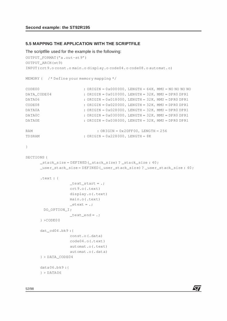
52/98
Second example: the ST92R195
5.5 MAPPING THE APPLICATION WITH THE SCRIPTFILE
The scriptfile used for the example is the following:OUTPUT_FORMAT(”a .out-st9”)
OUTPUT_ARCH(st9)
INPUT(crt9.o const.o main.o display.o code04.o code08.o automat.o)
MEMORY { /* Define your memory mapping */
CODE00 : ORIGIN = 0x000000, LENGTH = 64K, MMU = NO NO NO NO
DATA_CODE04 : ORIGIN = 0x010000, LENGTH = 32K, MMU = DPR0 DPR1
DATA06 : ORIGIN = 0x018000, LENGTH = 32K, MMU = DPR0 DPR1
CODE08 : ORIGIN = 0x020000, LENGTH = 32K, MMU = DPR0 DPR1
DATA0A : ORIGIN = 0x028000, LENGTH = 32K, MMU = DPR0 DPR1
DATA0C : ORIGIN = 0x030000, LENGTH = 32K, MMU = DPR0 DPR1
DATA0E : ORIGIN = 0x038000, LENGTH = 32K, MMU = DPR0 DPR1
RAM : ORIGIN = 0x20FF00, LENGTH = 256
TDSRAM : ORIGIN = 0x228000, LENGTH = 8K
}
SECTIONS {
_stack_size = DEFINED(_stack_size) ? _stack_size : 40;
_user_stack_size = DEFINED(_user_stack_size)? _user_stack_size : 40;
.text : {
_text_start = .;
crt9.o(.text)
display.o(.text)
main.o(.text)
_etext = .;
DO_OPTION_I;
_text_end = .;
} >CODE00
dat_cd04.bk9 :{
const.o(.data)
code04.o(.text)
automat.o(.text)
automat.o(.data)
} > DATA_CODE04
data06.bk9 :{
} > DATA06
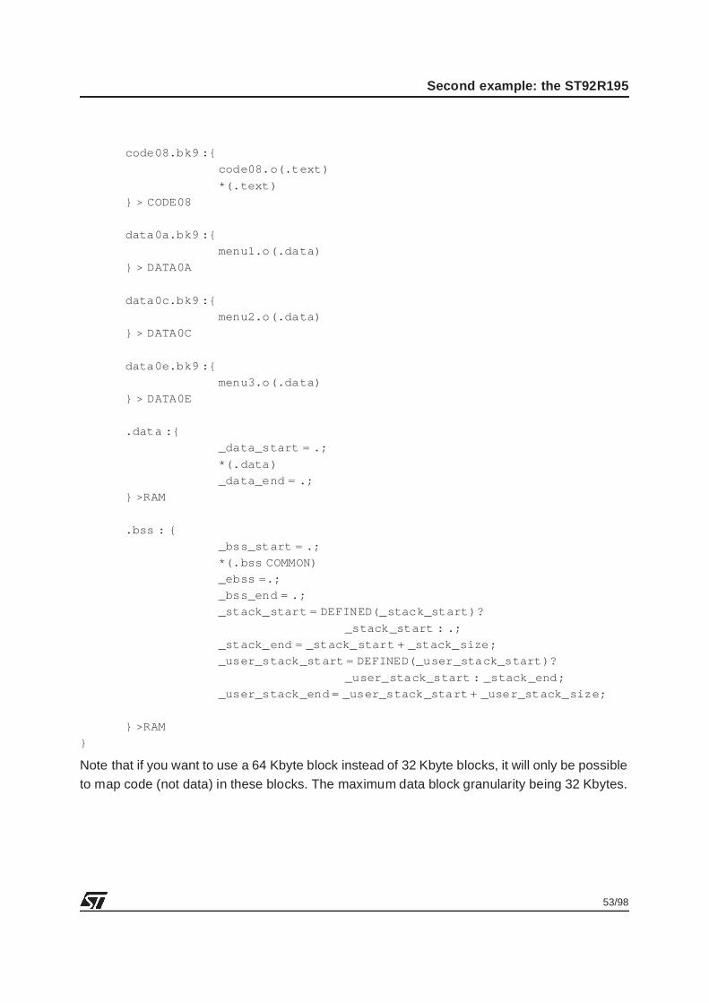
53/98
Second example: the ST92R195
code08.bk9 :{
code08.o(.text)
*(.text)
} > CODE08
data0a.bk9 :{
menu1.o(.data)
} > DATA0A
data0c.bk9 :{
menu2.o(.data)
} > DATA0C
data0e.bk9 :{
menu3.o(.data)
} > DATA0E
.data :{
_data_start = .;
*(.data)
_data_end = .;
} >RAM
.bss : {
_bss_start = .;
*(.bss COMMON)
_ebss =.;
_bss_end = .;
_stack_start = DEFINED(_stack_start)?
_stack_start : .;
_stack_end = _stack_start + _stack_size;
_user_stack_start = DEFINED(_user_stack_start)?
_user_stack_start : _stack_end;
_user_stack_end = _user_stack_start + _user_stack_size;
} >RAM
}
Note that if you want to use a 64 Kbyte block instead of 32 Kbyte blocks, it will only be possibleto map code (not data) in these blocks. The maximum data block granularity being 32 Kbytes.
54/98
Second example: the ST92R195
5.6 LIBRARIES
The V4.2 version of the compiler provides a complete set of libraries, depending on the dif-ferent compilation and link options. It is very important to select the correct libraries that will belinked with the application.
Refer to the V4.2 release note for the various libraries available.
In the example, the libraries used were:
– STDR9F.L
– LIBR9F.L
What must be understood is that because the far memory model is chosen, the libraries willalso have to be far, that is, called with calls and returned with rets .
It is also important to note that the objects extracted from the libraries will be placed by thelinker at the very end of the .text section. To be precise, they are placed in the segment thatcontains the *(.text) in the scriptfile.
The libraries also contain some initialized variables (.data). These variables need to bemapped correctly in the scriptfile.
5.7 THE COMPILER AND LINKER OPTIONS
For the compiler the options are:
-mfar : For far function memory model
-mlink : For ST9+ new instructions
-g : Get debug options
-O : Set the optimizer on
-tr9 : Use tr9 during compilation chain
-fomit-frame-pointer : Avoid frame pointer when not needed
-Wall : Get all possible warnings
-Wa,-ahld : Get a listing file
For the linker the options are:
-m : Generate a map file
-T : Use a scriptfile
-I : Get copy of init variables at startup
-mmu : Allow relocation and far memory model
55/98
Second example: the ST92R195
5.8 APPLICATION FILES
The necessary application files:
– MAKEFILE The file needed to make the application
– MAKEDEP The dependency description file
– MAIN.C Contains the main routine
– CONST.C Contains some CONSTANTS definition
– AUTOMAT.C Contains the various automaton routines
– MENU1.C Contains one menu line (constant string)
– MENU2.C Contains one menu line (constant string)
– MENU3.C Contains one menu line (constant string)
– CODE04.C Contains some routines of the automaton
– CODE08.C Contains some routines of the automaton
– DISPLAY.C Contains the OSD routines
– CRT9.ASM The startup file, contains the interrupt vectors, and calls mainit also initializes the ST9+ correctly
– ST92R195.SCR The scriptfile, contains the memory mapping description
– ST92R195.U The executable needed by the debugger
– ST92R195.HEX The hexadecimal file needed to program EPROM/OTPs
In addition, all header files and some ST9 macros are used and defined in:
ST9MACRO, DISPLAY.H, NEWREG.H, MMU.H, DEFINE.H and OSD_CONST.H.
5.9 THE DEBUGGER CONFIGURATION FILE
The scriptfile will generate the *.bk9 files. These files correspond to the various segments tobe loaded by the debugger. A file name ST92R195.BL9 was also created by the linker. It con-tains the loading order of each *.bk9 file needed by the debugger. To force the load of the seg-ments when loading the application with the debugger, a file needs to be created with thesame name as the executable (here ST92R195.U), with extension .GDB.
This file must contain:source ST92R195.BL9
The debugger will first load the HARDWARE.GDB file then the ST92R195.u and finally theST92R195.GDB.
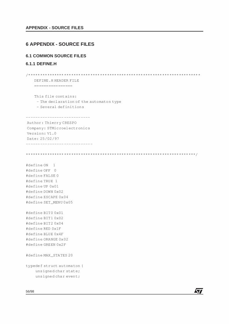
56/98
APPENDIX - SOURCE FILES
6 APPENDIX - SOURCE FILES
6.1 COMMON SOURCE FILES
6.1.1 DEFINE.H
/*************** *********************************************************
DEFINE.H HEADER FILE
================
This file contains:
- The declaration of the automaton type
- Several definitions
---------------- -----------
Author: Thierry CRESPO
Company: STMicroelectronics
Version: V1.0
Date: 25/02/97
---------------- ------------
**************** *******************************************************/
#define ON 1
#define OFF 0
#define FALSE 0
#define TRUE 1
#define UP 0x01
#define DOWN 0x02
#define ESCAPE 0x04
#define SET_MENU 0x05
#define BIT0 0x01
#define BIT1 0x02
#define BIT2 0x04
#define RED 0x1F
#define BLUE 0x4F
#define ORANGE 0x02
#define GREEN 0x2F
#define MAX_STATES 20
typedef struct automaton {
unsigned char state;
unsigned char event;
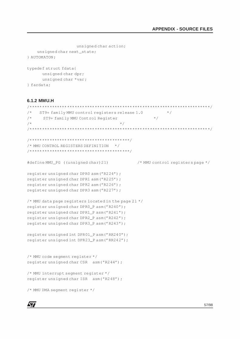
57/98
APPENDIX - SOURCE FILES
unsigned char action;
unsigned char next_state;
} AUTOMATON;
typedef struct fdata{
unsigned char dpr;
unsigned char *var;
} fardata;
6.1.2 MMU.H/*************** *********************************************************/
/* ST9+ family MMU control registers release 1.0 */
/* ST9+ family MMU Control Register */
/* */
/*************** *********************************************************/
/*************** *************************/
/* MMU CONTROL REGISTERS DEFINITION */
/*************** *************************/
#define MMU_PG ((unsigned char)21) /* MMU control registers page */
register unsigned char DPR0 asm(”R224”);
register unsigned char DPR1 asm(”R225”);
register unsigned char DPR2 asm(”R226”);
register unsigned char DPR3 asm(”R227”);
/* MMU data page registers located in the page 21 */
register unsigned char DPR0_P asm(”R240”);
register unsigned char DPR1_P asm(”R241”);
register unsigned char DPR2_P asm(”R242”);
register unsigned char DPR3_P asm(”R243”);
register unsigned int DPR01_P asm(”RR240”);
register unsigned int DPR23_P asm(”RR242”);
/* MMU code segment register */
register unsigned char CSR asm(”R244”);
/* MMU interrupt segment register */
register unsigned char ISR asm(”R248”);
/* MMU DMA segment register */
58/98
APPENDIX - SOURCE FILES
register unsigned char DMASR asm(”R249”);
/* MMU configuration registers */
register unsigned char EMR1 asm(”R245”);
#define EMR1_mc ((unsigned char)0x40) /* mode control */
#define EMR1_ds2n ((unsigned char)0x20) /* data strobe 2 enable */
#define EMR1_asaf ((unsigned char)0x10) /* address strobe as alternate
function */
#define EMR1_nmb ((unsigned char)0x08) /* no multiplexed bus */
#define EMR1_eto ((unsigned char)0x04) /* external toggle */
#define EMR1_bsz ((unsigned char)0x02) /* bus size */
#define EMR1_romless ((unsigned char)0x01) /* romless */
register unsigned char EMR2 asm(”R246”);
#define EMR2_bromless ((unsigned char)0x80) /* Boot-Romless */
#define EMR2_encsr ((unsigned char)0x40) /* ENable Code Segment register
*/
#define EMR2_dprrem ((unsigned char)0x20) /* data Page register Reapped */
#define EMR2_memsel ((unsigned char)0x10) /* MEMory SELect */
#define EMR2_pas ((unsigned char)0x0C) /* Program memory Address strobe
Stretch */
#define EMR2_das ((unsigned char)0x03) /* Data memory Address strobe
stretch */
#define SET_DPR_SYSTEMEMR2 |= EMR2_dprrem
#define SEG(f) ({ \
unsigned char __seg; \
asm(”ld %0, #seg %1” : ”=r”(__seg) : ”m”(f) ); \
__seg; \
})
#define SOF(f) ({ \
void *__sof; \
asm(”ldw %0, #sof %1” : ”=r”(__sof) : ”m”(f) ); \
__sof; \
})
#define PAG(f) ({ \
unsigned char __pag; \
59/98
APPENDIX - SOURCE FILES
asm(”ld %0, #pag %1” : ”=r”(__pag) : ”m”(f) ); \
__pag; \
})
#define POF(f) ({ \
void *__pof; \
asm(”ldw %0, #pof %1” : ”=r”(__pof) : ”m”(f) ); \
__pof; \
})
/* Inter-segment function call through a 3 byte pointer:
StructFuncAddress x;
...
x = AddressOf (func);
...
FarCall (x);
*/
/* 3 byte structure hosting a far function pointer */
typedef struct {
unsigned char seg;
void *sof;
} StructFuncAddress;
/* Operator creating a temporary object of type StructFuncAddress */
#define AddressOf(f) (StructFuncAddress){ SEG( f), SOF( f) }
/* Call through a StructFuncAddresspointer */
#define FarCall(f) asm(”calls (%0),(%1)” : : ”r”(f.seg),
”r”(f.sof))
#define FarCallPointer(f) FarCall(f)
60/98
APPENDIX - SOURCE FILES
6.1.3 ST9MACRO.H/*************** *********************************************************
ST9MACRO.H header FILE
======================
This file contains macros used in the C
---------------- -----------
Author: Thierry CRESPO
Company: STMicroelectronics
Version: V1.0
Date: 25/02/97
---------------- ------------
**************** *******************************************************/
/*************** **********************/
/* C macros for inline assembly code */
/*************** **********************/
#define halt() asm(”halt”); /* halt instruction */
#define spm() asm(”spm”); /* set program memory */
#define sdm() asm(”sdm”); /* set data memory */
#define ei() asm(”ei”); /* enable interrupts*/
#define di() asm(”di”); /* disable interrupts*/
#define NOP asm (”nop”); /* 6 cycle clock tempo */
#define SAVE_PAGE asm(”pushu R234”);
#define RESTORE_PAGE asm(”popu R234”);
/*************** ****************************************/
/* C macros for inline assembly code with an operand */
/*************** ****************************************/
/* set page pointer to value page */
#define spp(page) asm(”spp %0”:: ”i” (page));
/* set working register pointer to value bank */
#define srp(bank) asm(”srp %0”:: ”i” (bank));
/* load a value to a working register */
#define ldw_rr_xx(reg,value) asm(”ldw rr%Q0,%1”:: ”i” (reg) ,”RR” (value));
61/98
APPENDIX - SOURCE FILES
#define RESTORE_DPR asm(”popw RR240”);
#define SAVE_DPR asm(”pushw RR240”);
6.1.4 DISPLAY.H/*************** ********STMicroelectronics ************************
FILENAME : DISPLAY.H
VERSION : V0.0
DATE : February 20, 1997
AUTHOR(s) : Thierry CRESPO
PROCESSOR : ST92195
DESCRIPTION : This module contains constant definitions and function
prototypes.
MODIFICATIONS:
-
-
-
**************** ************************************************************
*/
unsigned char *write_character(unsignedchar *, unsigned char);
const unsigned char *write_MBT_BUFFER(constunsigned char *);
void Init_Display(void);
void Enable_Display(unsignedchar);
void Disable_Display(unsignedchar);
unsigned char *get_DRAM_address(unsignedchar, unsigned char);
void Show_Menu();
void Clear_Menu();
#define DISPLAY_CHARACTERS0x00
#define DISPLAY_ATTRIBUTES 0xFF
#define ROW_ALL 0xFF
#define ROW_1 1
#define ROW_2 2
#define ROW_3 3
#define ROW_4 4
#define ROW_5 5
#define ROW_6 6
#define ROW_7 7
#define ROW_8 8
#define ROW_9 9
#define ROW_10 10
#define ROW_11 11
#define ROW_12 12
#define ROW_13 13
62/98
APPENDIX - SOURCE FILES
#define ROW_14 14
#define ROW_15 15
#define ROW_16 16
#define ROW_17 17
#define ROW_18 18
#define ROW_19 19
#define ROW_20 20
#define ROW_21 21
#define ROW_22 22
#define ROW_23 23
#define FLASH 0x08
#define STEADY 0x09
#define HORIZONTAL_DELAY 0x30
#define HORIZONTAL_POSITION0x70
#define VERTICAL_POSITION0x0E
6.2 THE FIRST APPLICATION EXAMPLE SOURCE FILES : THE ST92195
6.2.1 MAIN.C/*************** ********STMicroelectronics ************************
FILENAME : MAIN.C
VERSION : V1.0
DATE : February 20, 1997
AUTHOR(s) : Thierry CRESPO
PROCESSOR : ST92195
DESCRIPTION : This file contains:
- the main routine
- the Wait_For_Event routine
The purpose of the main is to do an infini te loop waiting for
events and to treat the received events depending on the
automaton.
MODIFICATIONS:
**************** *******************************************************/
#include ”define.h”
#include ”display.h”
#include ”st9macro.h”
#include <stdlib.h>
char Wait_For_Event();
63/98
APPENDIX - SOURCE FILES
void Wait_For_Second(unsignedchar);
AUTOMATON Run_Automaton(AUTOMATON);
/*************** *********************************************************
Variable Definitions
**************** ********************************************************/
extern const struct automaton AUTOMATON_TABLE[9];
char Init_var []=” THIS IS AN INITIALIZED VARIABLE ”;
AUTOMATON OSD_Menu;
/*************** **************************************************
void main(void)
Object: Contains the main routine. It init ializes the variables,
waits for an input event, when an input event is
received, it scans the automaton table, then modifies the
state of tit calls the automaton and does the loop forever.
input: none
output: none
**************** *************************************************/
void main() {
Init_Display();
OSD_Menu.state = OFF; /* Initialization of the automaton */
OSD_Menu.event = SET_MENU; /* Set first Event to show the menu */
OSD_Menu = Run_Automaton(OSD_Menu); /* Perform Initial ization of Menu */
while(1) {
OSD_Menu.event = Wait_For_Event(); /* Wait for an input Event */
/* Return the event */
OSD_Menu = Run_Automaton(OSD_Menu);/* Perform Automaton depending on */
/* Event
received */
}
}
/*************** **************************************************
AUTOMATON Run_Automaton(AUTOMATONmenu)
Object: This routine scan the automaton depending on the
64/98
APPENDIX - SOURCE FILES
state and event of the current automaton.
It returns the updated automaton.
input: AUTOMATON
output: AUTOMATON => updated automaton
**************** *************************************************/
AUTOMATON Run_Automaton(AUTOMATONmenu)
{
unsigned char count;
count = 0; /* Counter to scan au-
tomaton table */
while(1) /* Scan the AUTOMATON table to */
{ /* find the corresponding one */
if (( menu.state == AUTOMATON_TABLE[count].state)
&& ( menu.event == AUTOMATON_TABLE[count] .event)){
/* Get the state and event */
/* Udate the automaton */
/* Perform the action */
menu.action = (void *) AUTOMATON_TABLE[count].action;
menu.state = AUTOMATON_TABLE[count].next_state;
menu.action();
return (menu);
}
else count++;
if (count >= MAX_STATES) return(menu); /* If table overflow
*/
}
return(menu);
}
/*************** **************************************************
char Wait_For_Event(void)
Object: The routine selects a random char value, if this value
corresponds to a event (01, 02, 04) then it returns
the event number. It loops until a event is found
input: none
output: Event => a char, the event
65/98
APPENDIX - SOURCE FILES
Events can be:
UP
DOWN
ESCAPE
SET_MENU
**************** *************************************************/
char Wait_For_Event() {
char Event;
while(1) {
Event = (char) rand(); /* Get a random char */
switch (Event) {
case UP:
{
Wait_For_Second(4);
return(UP); /* Return event is same */
}
case DOWN:
{
Wait_For_Second(4);
return(DOWN);
}
case ESCAPE:
{
Wait_For_Second(4);
return(ESCAPE);
}
case SET_MENU:
return(SET_MENU);
default:break;
}
}
}
/*************** ********************************************
void Wait_For_Second(unsignedchar number)
This routine does a tempo
Input: number => approximate number of seconds to wait
Ouput: none
**************** ********************************************/
66/98
APPENDIX - SOURCE FILES
void Wait_For_Second(unsignedchar number)
{
unsigned int i;
while (number != 0)
{
for (i=0xfff2; i!=0; i--)
{
asm(”nop”);
asm(”nop”);
asm(”nop”);
asm(”nop”);
asm(”nop”);
}
number--;
}
}
6.2.2 ACTIONS.C/*************** *********************************************************
ACTION.C SOURCE FILE
====================
This file contains all the functions implementing
the actions of the automaton.
---------------- -----------
Author: Thierry CRESPO
Company: STMicroelectronics
Version: V1.0
Date: 25/02/97
---------------- ------------
**************** *******************************************************/
#include ”define.h”
#include ”display.h”
#include ”st9macro.h”
void Red_to_Blue();
void Blue_to_Red();
void Blue_to_Green();
void Green_to_Blue();
void Green_to_Red();
67/98
APPENDIX - SOURCE FILES
void Switch_Attr(char, char);
/*************** **************************************************
void Switch_Attr(char, char);
Object: Set a port bit high or low
input: the bort bit (char), the status (char)
output: none
**************** *************************************************/
void Switch_Attr(char color, char state)
{
unsigned char *j;
unsigned char row_number = RED;
switch (color)
{
case RED: row_number = 10;
break;
case BLUE: row_number = 11;
break;
case GREEN: row_number = 12;
break;
default:
break;
}
if (state == ON)
{
j = get_DRAM_address(DISPLAY_ATTRIBUTES,row_number);
j = j + 9;
j = write_character(j,0xA0);
}
else
{
j = get_DRAM_address(DISPLAY_ATTRIBUTES,row_number);
j = j + 9;
j = write_character(j,0x80);
}
}
68/98
APPENDIX - SOURCE FILES
/*************** **************************************************
Object: Toggle the Attr to obtain the state
corresponding to the AUTOMATON table
input: none
output: none
**************** *************************************************/
void Red_to_Green(){
Switch_Attr(GREEN, ON);
Switch_Attr(RED, OFF);
}
void Red_to_Blue(){
Switch_Attr(BLUE, ON);
Switch_Attr(RED, OFF);
}
void Blue_to_Red(){
Switch_Attr(BLUE, OFF);
Switch_Attr(RED, ON);
}
void Blue_to_Green(){
Switch_Attr(BLUE, OFF);
Switch_Attr(GREEN, ON);
}
void Green_to_Blue(){
Switch_Attr(GREEN, OFF);
Switch_Attr(BLUE, ON);
}
void Green_to_Red(){
Switch_Attr(GREEN, OFF);
Switch_Attr(RED, ON);
}
6.2.3 CONST.C/*************** *********************************************************
CONST.C SOURCE FILE
================
This file contains:
- The automaton table to be put in ROM
- The CONSTANT TABLE for On Screen Display
---------------- -----------
69/98
APPENDIX - SOURCE FILES
Author: Thierry CRESPO
Company: STMicroelectronics
Version: V1.0
Date: 25/02/97
---------------- ------------
**************** *******************************************************/
#include ”define.h”
#include ”display.h”
extern void Clear_Menu();
extern void Red_to_Green();
extern void Red_to_Blue();
extern void Blue_to_Red();
extern void Blue_to_Green();
extern void Green_to_Blue();
extern void Green_to_Red();
const char CONSTANT1[]=”THIS IS THE FIRST CONSTANT”;
const char BLANK[]=” ”;
const char CONSTANT2[]=”THIS IS THE SECOND CONSTANT”;
const struct automaton AUTOMATON_TABLE[MAX_STATES]= {
{RED, UP, (void *) &Red_to_Green,GREEN},
{RED, DOWN, (void *) &Red_to_Blue,BLUE},
{RED, ESCAPE, (void *) &Clear_Menu,OFF},
{OFF, SET_MENU, (void *) &Show_Menu,RED},
{BLUE, UP, (void *) &Blue_to_Red,RED},
{BLUE, DOWN, (void *) &Blue_to_Green,GREEN},
{BLUE, ESCAPE, (void *) &Clear_Menu,OFF},
{GREEN, UP, (void *) &Green_to_Blue,BLUE},
{GREEN, DOWN, (void *) &Green_to_Red,RED},
{GREEN, ESCAPE, (void *) &Clear_Menu,OFF},
};
const unsigned char ST92195_STRING[]= ”ST92195 Application Note”;
const unsigned char THOMSON_STRING[]= ” STMicroelectronics ”;
const unsigned char DEMO_STRING[] = ” DEMO ”;
70/98
APPENDIX - SOURCE FILES
6.2.4 DISPLAY.C/*************** ********STMicroelectronics ************************
FILENAME : DISPLAY.C
VERSION : V0.0
DATE : February 20, 1997
AUTHOR(s) : Thierry CRESPO
PROCESSOR : ST92195
DESCRIPTION : This file contains the source code for the On Screen Display
Driver.
MODIFICATIONS:
**************** ************************************************************
*/
#include ”define.h”
#include ”display.h”
#include ”newreg.h”
#include ”st9macro.h”
#include ”osd_cons.h”
/
**************** ************************************************************
*
INPUTS : none
OUTPUTS : ST9 OSD registers
DESCRIPTION: This function initializes the display cell for both TV mode (Menu,
Stats...) and Teletext mode.
**************** ************************************************************
*/
void Init_Display(void)
{
unsigned int i;
spp(SCCR_PG); /* Select synchro controller page */
CSYCT = 0x00; /* Select VSYNC and HSYNC from VSYNC and HSYNC inputs (not
from CVBS) */
/* Select HSYNC and VSYNC polarity as well as the phase
delay */
/*between HSYNC and VSYNC which is chassis hardware
dependant */
CSYSU = 0xc4;
spp(TCCR_PG);
SKCCR = 0x0A;
for (i=0x1fff ; i!=0 ; i--);
SKCCR = 0x8a;
71/98
APPENDIX - SOURCE FILES
for (i=0x1fff ; i!=0 ; i--);
PXCCR = 0x80;
SLCCR = 0x80;
spp(TDSRAMC2_PG);
CONFIG = 0x07;
spp(DCR1_PG);
HBLANK = HORIZONTAL_DELAY;
HPOS = HORIZONTAL_POSITION;
VPOS = VERTICAL_POSITION;
FSC = 0xaf;
HSC = 0x3f; /* header,status 1,2 enable */
NCS = 0x07;
CHPOS = 0x99;
CVPOS = 0x00;
SCL = 0x00; /* SCROLLING DISABLE */
SCH = 0x2F;
DCM0R = 0x84; /* display en,semitransparent en,fr inge en,conceal en,global
fringe en,global rounding en,screen format,single/double*/
DCM1R = 0x0d;
TDSRAML = 0x80;
HSC = 0x0;
DE0 = 0x0;
DE1 = 0x0;
DE2 = 0x0;
spp(DCR2_PG);
DC = 0x7F;
}
/
**************** ************************************************************
*
INPUTS : Row number to display
OUTPUTS : ST9 OSD registers
DESCRIPTION: This function displays a row.
**************** ************************************************************
*/
void Enable_Display(unsignedchar row_number)
{
unsigned char i, j; /* Temporary storage */
/* Set bit position depending on the row number */
for (i=1, j=row_number; j>1; j--)
72/98
APPENDIX - SOURCE FILES
asm (”rol %0” : :”r”(i));
/* Enable selected row */
spp(DCR1_PG);
if (row_number == ROW_ALL)
{
DE0 = 0xff;
DE1 = 0xff;
DE2 = 0xff;
return;
}
if (row_number <= ROW_8)
{
DE0 = DE0 | i;
return;
}
if (row_number <= ROW_16)
{
DE1 = DE1 | i;
return;
}
if (row_number <= ROW_23)
{
DE2 = DE2 | i;
}
}
/
**************** ************************************************************
*
INPUTS : Row number to display
OUTPUTS : ST9 OSD registers
DESCRIPTION: This function displays a row.
**************** ************************************************************
*/
void Disable_Display(unsignedchar row_number)
{
unsigned char i, j; /* Temporary storage */
/* Set bit position depending on the row number */
for (i=1, j=row_number; j>1; j--)
asm (”rol %0” : :”r”(i));
/* Disable selected row */
spp(DCR1_PG);
if (row_number == ROW_ALL)
73/98
APPENDIX - SOURCE FILES
{
DE0 = 0x00;
DE1 = 0x00;
DE2 = 0x00;
return;
}
if (row_number <= ROW_8)
{
DE0 = DE0 & ~i;
return;
}
if (row_number <= ROW_16)
{
DE1 = DE1 & ~i;
return;
}
if (row_number <= ROW_23)
{
DE2 = DE2 & ~i;
}
}
/
**************** ************************************************************
*
INPUTS : Row number
OUTPUTS : DRAM position
DESCRIPTION: This function returns the DRAM location to start with according
to the row number.
**************** ************************************************************
*/
unsigned char *get_DRAM_address(unsignedchar selection, unsigned char
row_position)
{
if (selection == DISPLAY_CHARACTERS)
return (unsigned char *)(0x8000 + ((row_posi tion - 1) * 40));
else
return (unsigned char *)(0x8400 + ((row_posi tion - 1) * 40));
}
/
**************** ************************************************************
*
INPUTS : Character chain pointer
OUTPUTS : Character chain pointer
DESCRIPTION: This function copies the character chain into the
74/98
APPENDIX - SOURCE FILES
Multi byte transfer buffer.
**************** ************************************************************
*/
const unsigned char *write_MBT_BUFFER(constunsigned char *cha_pointer)
{
unsigned char i;
spp(TDSRAMC0_PG);
asm volatile (” ld %0,#0xf0
repeat1:
ld (%0)+,%1+
cp %0,#0
jxnz repeat1 ” :”=r”(i) :”m”(*cha_pointer));
spp(TDSRAMC1_PG);
asm volatile (” ld %0,#0xf0
repeat2:
ld (%0)+,%1+
cp %0,#0
jxnz repeat2 ” :”=r”(i) :”m”(*cha_pointer));
spp(TDSRAMC2_PG);
asm volatile (” ld %0,#0xf0
repeat3:
ld (%0)+,%1+
cp %0,#0xf8
jxnz repeat3 ” :”=r”(i) :”m”(*cha_pointer));
BUFC = 0x01;
asm(” nop
nop ”);
while(BUFC & 0x01)
asm(”nop”);
return cha_pointer;
}
/
**************** ************************************************************
*
INPUTS : DRAM pointer - Point the location to start with
Character to write into the DRAM
OUTPUTS : Return the next DRAM location
DESCRIPTION: This function writes the given character.
**************** ************************************************************
*/
unsigned char *write_character(unsignedchar *pointer,
unsigned char character)
{
*pointer++ = character;
return pointer;

75/98
APPENDIX - SOURCE FILES
}
/
**************** ************************************************************
*
INPUTS : .DRAM pointer - Point the location to start with
Character to write into the DRAM
.character
.number
OUTPUTS : Return the next DRAM location
DESCRIPTION: This function writes the given character.
**************** ************************************************************
*/
unsigned char *write_character_n(unsignedchar *pointer,unsignedchar character
,unsigned char number)
{
while(number!=0)
{
pointer = write_character(pointer,character);
number--;
}
return pointer;
}
/
**************** ************************************************************
*
INPUTS : DRAM pointer - Point the location to start with
String pointer - Point the first character to write into the DRAM
OUTPUTS : Return the next DRAM location
see write_character
DESCRIPTION: This function writes the given string.
**************** ************************************************************
*/
unsigned char * Display_String(unsignedchar *pointer,
const unsigned char *string_pointer)
{
/* WARNING - do not modify working registers */
while (*string_pointer != ’\0’)
pointer = write_character(pointer, *string_pointer++);
return pointer;
}
/
**************** ************************************************************
*
INPUTS : none
76/98
APPENDIX - SOURCE FILES
OUTPUTS : none
DESCRIPTION: This function clear a TDSRAM row in character area
**************** ************************************************************
*/
void Clear_DRAM_Row(unsignedchar row_number)
{
unsigned char i;
unsigned char *j;
j = get_DRAM_address(DISPLAY_CHARACTERS,row_number);
for (i=40; i!=0; i--)
{
j = write_character(j,0x00);
}
j = get_DRAM_address(DISPLAY_ATTRIBUTES,row_number);
for (i=40; i!=0; i--)
{
j = write_character(j,0x20);
}
}
/
**************** ************************************************************
*
INPUTS : none
OUTPUTS : none
DESCRIPTION: This function displays a simple menu
**************** ************************************************************
*/
void Show_Menu()
{
unsigned char *j;
unsigned char *i;
Clear_DRAM_Row(10);
Clear_DRAM_Row(11);
Clear_DRAM_Row(12);
j = get_DRAM_address(DISPLAY_CHARACTERS,ROW_10);
j = j + 10;
i = (unsigned char *) ST92195_STRING;
Display_String(j, i);
j = get_DRAM_address(DISPLAY_ATTRIBUTES,ROW_10);
j = j + 8;
j = write_character(j,RED);
j = write_character(j,0xA0);
77/98
APPENDIX - SOURCE FILES
j = write_character_n(j,RED,24);
j = write_character(j,0x80);
j = get_DRAM_address(DISPLAY_CHARACTERS,ROW_11);
j = j + 10;
i = (unsigned char *) THOMSON_STRING;
Display_String(j, i);
j = get_DRAM_address(DISPLAY_ATTRIBUTES,ROW_11);
j = j + 8;
j = write_character(j,BLUE);
j = write_character(j,0x80);
j = write_character_n(j,BLUE,24);
j = write_character(j,0x80);
j = get_DRAM_address(DISPLAY_CHARACTERS,ROW_12);
j = j + 10;
i = (unsigned char *) DEMO_STRING;
Display_String(j, i);
j = get_DRAM_address(DISPLAY_ATTRIBUTES,ROW_12);
j = j + 8;
j = write_character(j,GREEN);
j = write_character(j,0x80);
j = write_character_n(j,GREEN,24);
j = write_character(j,0x80);
Enable_Display(ROW_10);
Enable_Display(ROW_11);
Enable_Display(ROW_12);
}
/
**************** ************************************************************
*
INPUTS : none
OUTPUTS : none
DESCRIPTION: This function displays a simple menu
**************** ************************************************************
*/
void Clear_Menu(void)
{
Disable_Display(ROW_10);
Disable_Display(ROW_11);
Disable_Display(ROW_12);
}
78/98
APPENDIX - SOURCE FILES
6.3 THE SECOND APPLICATION EXAMPLE SOURCE FILES : THE ST92R195
6.3.1 MAIN.C/*************** ********STMicroelectronics ************************
FILENAME : MAIN.C
VERSION : V1.0
DATE : February 20, 1997
AUTHOR(s) : Thierry CRESPO
PROCESSOR : ST92R195
DESCRIPTION : This file contains:
- the main routine
- the Wait_For_Event routine
The purpose of the main is to do an infini te loop waiting for
events and to treat the received events depending on the
automaton.
MODIFICATIONS:
-
**************** ************************************************************
*/
#include ”mmu.h”
#include ”define.h”
#include ”display.h”
#include ”st9macro.h”
#include <stdlib.h>
static char Wait_For_Event();
static void Wait_For_Second(unsignedchar);
extern AUTOMATON Run_Automaton(AUTOMATON);
/*************** *********************************************************
Variable Definitions
**************** ********************************************************/
extern const struct automaton AUTOMATON_TABLE[9];
char Init_var []=” THIS IS AN INITIALIZED VARIABLE ”;
AUTOMATON OSD_Menu;
/
**************** ************************************************************
*
FUNCTION : void main(void)
79/98
APPENDIX - SOURCE FILES
INPUTS : none
OUTPUTS : none
DESCRIPTION:
Contains the main routine. It initializes the varia-
bles,
waits for an input event, when an input event is
received, it scans the automaton table, then modifies the
state of tit calls the automaton and does the loop forever.
**************** *************************************************/
void main() {
Init_Display();
OSD_Menu.state = OFF; /* Initialization of the automaton */
OSD_Menu.event = SET_MENU; /* Set first Event to show the menu */
OSD_Menu = Run_Automaton(OSD_Menu); /* Perform Initial ization of Menu */
while(1) {
OSD_Menu.event = Wait_For_Event(); /* Wait for an input Event */
/* Return the event */
OSD_Menu = Run_Automaton(OSD_Menu);/* Perform Automaton depending on */
/* Event
received */
}
}
/*************** **************************************************
FUNCTION : static char Wait_For_Event(void)
INPUTS : Row number to display
OUTPUTS : Event
DESCRIPTION:
The routine selects a random char value, if this value
corresponds to a event (01, 02, 04, 05 ...) then it returns
the event number. It loops until a event is found and
does a small tempo for visual effect.
Events can be:
UP
DOWN
ESCAPE

80/98
APPENDIX - SOURCE FILES
SET_MENU
**************** *************************************************/
static char Wait_For_Event() {
unsigned char Event;
while(1) {
Event = (char) rand() % 6; /* Get a random char */
switch (Event) {
case UP:
{
Wait_For_Second(4);
return(UP); /* Return event is same */
}
case DOWN:
{
Wait_For_Second(4);
return(DOWN);
}
case ESCAPE:
{
Wait_For_Second(4);
return(ESCAPE);
}
case SET_MENU:
return(SET_MENU);
default:break;
}
}
}
/
**************** ************************************************************
*
FUNCTION : static void Wait_For_Second(unsignedchar number)
INPUTS : number => approximate number of seconds to wait
OUTPUTS : none
DESCRIPTION: This routine does a tempo
**************** ********************************************/
static void Wait_For_Second(unsignedchar number)
{
unsigned int i;
while (number != 0)
{
81/98
APPENDIX - SOURCE FILES
for (i=0xfff2; i!=0; i--)
{
asm(”nop”);
asm(”nop”);
asm(”nop”);
asm(”nop”);
asm(”nop”);
}
number--;
}
}
6.3.2 DISPLAY.C
/*************** ********STMicroelectronics ************************
FILENAME : DISPLAY.C
VERSION : V1.0
DATE : February 20, 1997
AUTHOR(s) : Thierry CRESPO
PROCESSOR : ST92R195
DESCRIPTION : This file contains the source code for the On Screen Display
Driver.
MODIFICATIONS:
-
-
-
**************** ************************************************************
*/
#include ”define.h”
#include ”display.h”
#include ”newreg.h”
#include ”st9macro.h”
#include ”osd_cons.h”
#include ”mmu.h”
/
**************** ************************************************************
*
INPUTS : none
OUTPUTS : ST9 OSD registers
DESCRIPTION: This function initializes the display cell for both TV mode (Menu,
Stats...) and Teletext mode.
**************** ************************************************************
*/
void Init_Display(void)

82/98
APPENDIX - SOURCE FILES
{
unsigned int i;
spp(SCCR_PG); /* Select synchro controller page */
CSYCT = 0x00; /* Select VSYNC and HSYNC from VSYNC and HSYNC inputs (not
from CVBS) */
/* Select HSYNC and VSYNC polarity as well as the phase
delay between */
/* HSYNC and VSYNC which is chassis hardware dependant
*/
CSYSU = 0xc4;
spp(TCCR_PG);
SKCCR = 0x0A;
for (i=0x1fff ; i!=0 ; i--);
SKCCR = 0x8a;
for (i=0x1fff ; i!=0 ; i--);
PXCCR = 0x80;
SLCCR = 0x80;
spp(TDSRAMC2_PG);
CONFIG = 0x03;
spp(DCR1_PG);
HBLANK = HORIZONTAL_DELAY;
HPOS = HORIZONTAL_POSITION;
VPOS = VERTICAL_POSITION;
FSC = 0xaf;
HSC = 0x3f; /* header,status 1,2 enable */
NCS = 0x07;
CHPOS = 0x99;
CVPOS = 0x00;
SCL = 0x00; /* SCROLLING DISABLE */
SCH = 0x2F;
DCM0R = 0x84; /* display en,semitransparent en,fringe en,con-
ceal en, */
/* global fringe en,global rounding
en,screen format,single/double */
DCM1R = 0x0d;
TDSRAML = 0x80;
HSC = 0x0;
DE0 = 0x0;
DE1 = 0x0;
DE2 = 0x0;
83/98
APPENDIX - SOURCE FILES
spp(DCR2_PG);
DC = 0x7F;
}
/
**************** ************************************************************
*
INPUTS : Row number to display
OUTPUTS : ST9 OSD registers
DESCRIPTION: This function enables the display of a row.
**************** ************************************************************
*/
void Enable_Display(unsignedchar row_number)
{
unsigned char i, j; /* Temporary storage */
SAVE_PAGE; /* Save the register page */
/* Set bit position depending on the row number */
for (i=1, j=row_number; j>1; j--)
asm (”rol %0” : :”r”(i));
/* Enable selected row */
spp(DCR1_PG);
if (row_number == ROW_ALL)
{
DE0 = 0xff;
DE1 = 0xff;
DE2 = 0xff;
RESTORE_PAGE; /* Restore the register page */
return;
}
if (row_number <= ROW_8)
{
DE0 = DE0 | i;
RESTORE_PAGE; /* Restore the register page */
return;
}
if (row_number <= ROW_16)
{
DE1 = DE1 | i;
RESTORE_PAGE; /* Restore the register page */
return;
}
if (row_number <= ROW_23)
{
84/98
APPENDIX - SOURCE FILES
DE2 = DE2 | i;
}
RESTORE_PAGE; /* Restore the register page */
}
/
**************** ************************************************************
*
INPUTS : Row number to display
OUTPUTS : ST9 OSD registers
DESCRIPTION: This function disable the display of a row.
**************** ************************************************************
*/
void Disable_Display(unsignedchar row_number)
{
unsigned char i, j; /* Temporary storage */
SAVE_PAGE; /* Save the register page */
/* Set bit position depending on the row number */
for (i=1, j=row_number; j>1; j--)
asm (”rol %0” : :”r”(i));
/* Disable selected row */
spp(DCR1_PG);
if (row_number == ROW_ALL)
{
DE0 = 0x00;
DE1 = 0x00;
DE2 = 0x00;
RESTORE_PAGE; /* Restore the register page */
return;
}
if (row_number <= ROW_8)
{
DE0 = DE0 & ~i;
RESTORE_PAGE; /* Restore the register page */
return;
}
if (row_number <= ROW_16)
{
DE1 = DE1 & ~i;
RESTORE_PAGE; /* Restore the register page */
return;
}
if (row_number <= ROW_23)
85/98
APPENDIX - SOURCE FILES
{
DE2 = DE2 & ~i;
}
RESTORE_PAGE; /* Restore the register page */
}
/
**************** ************************************************************
*
INPUTS : Row number
OUTPUTS : DRAM position
DESCRIPTION: This function returns the DRAM location to start with according
to the row number. Position needed for writ ing the OSD menus.
**************** ************************************************************
*/
unsigned char *get_DRAM_address(unsignedchar selection, unsigned char
row_position)
{
if (selection == DISPLAY_CHARACTERS)
return (unsigned char *)(0x8000 + ((row_posi tion - 1) * 40));
else
return (unsigned char *)(0x8400 + ((row_posi tion - 1) * 40));
}
/
**************** ************************************************************
*
INPUTS : DRAM pointer - Point the location to start with
Character to write into the DRAM
OUTPUTS : Return the next DRAM location
DESCRIPTION: This function writes the given character.
It doesn’t need any DPR management as DPR2 points
always to the TDSRAM.
**************** ************************************************************
*/
unsigned char *write_character(unsignedchar *pointer,
unsigned char character)
{
*pointer++ = character;
return pointer;
}
/
**************** ************************************************************
*
INPUTS : .DRAM pointer - Point the location to start with
Character to write into the DRAM
86/98
APPENDIX - SOURCE FILES
.character
.number
OUTPUTS : Return the next DRAM location
DESCRIPTION: This function writes the given character n times.
It doesn’t need any DPR management as DPR2 points
always to the TDSRAM.
**************** ************************************************************
*/
unsigned char *write_character_n(unsignedchar *pointer,unsignedchar character
,unsigned char number)
{
while(number!=0)
{
pointer = write_character(pointer,character);
number--;
}
return pointer;
}
/
**************** ************************************************************
*
INPUTS : DRAM pointer - Points the location to start with
String pointer - A struct to write into the DRAM.
This is a struct containing the DPR of the data
and the first character.
OUTPUTS : Return the next DRAM location
see write_character
DESCRIPTION: This function writes the given string in TDSRAM
**************** ************************************************************
*/
unsigned char * Display_String(unsignedchar *pointer,
fardata string_pointer)
{
SAVE_PAGE; /* Store the Page register */
spp(MMU_PG); /* Set the MMU page (21) */
SAVE_DPR; /* Save the old DPR0 & 1 */
DPR0_P = string_pointer.dpr;/* Set DPR0 to the struct DPR value */
DPR1_P = DPR0_P + 1; /* Set DPR1 contiguous to DPR0 */
/* WARNING - do not modify working registers */
while (*string_pointer.var != ’\0’)
pointer = write_character(pointer, *string_pointer.var++);
RESTORE_DPR; /* Restore the DPR0 & 1 */
RESTORE_PAGE; /* Restore the register page */
87/98
APPENDIX - SOURCE FILES
return pointer; /* Return the incremented address */
}
/
**************** ************************************************************
*
INPUTS : none
OUTPUTS : none
DESCRIPTION: This function clears a TDSRAM row in character area
**************** ************************************************************
*/
void Clear_DRAM_Row(unsignedchar row_number)
{
unsigned char i;
unsigned char *j;
j = get_DRAM_address(DISPLAY_CHARACTERS,row_number);
for (i=40; i!=0; i--)
{
j = write_character(j,0x00);
}
j = get_DRAM_address(DISPLAY_ATTRIBUTES,row_number);
for (i=40; i!=0; i--)
{
j = write_character(j,0x20);
}
}
/
**************** ************************************************************
*
INPUTS : none
OUTPUTS : none
DESCRIPTION: This function displays a simple menu made of 3 lines
in row 10, 11 & 12.
It uses far data.
**************** ************************************************************
*/
void Show_Menu()
{
unsigned char *j;
fardata x;
Clear_DRAM_Row(10); /* Clear OSD rows */
Clear_DRAM_Row(11);
Clear_DRAM_Row(12);
88/98
APPENDIX - SOURCE FILES
j = get_DRAM_address(DISPLAY_CHARACTERS,ROW_10);
j = j + 10;
x.var = (unsigned char *) ST92195_STRING; /* Initialize the fardata struct
*/
x.dpr = PAG(ST92195_STRING);
Display_String(j, x); /* Copy the string in TDSRAM */
j = get_DRAM_address(DISPLAY_ATTRIBUTES,ROW_10);/* Set attrbutes for row
10 */
j = j + 8;
j = write_character(j,RED);
j = write_character(j,0xA0);
j = write_character_n(j,RED,24);
j = write_character(j,0x80);
j = get_DRAM_address(DISPLAY_CHARACTERS,ROW_11);
j = j + 10;
x.var = (unsigned char *) THOMSON_STRING;
x.dpr = PAG(THOMSON_STRING);
Display_String(j, x);
j = get_DRAM_address(DISPLAY_ATTRIBUTES,ROW_11);
j = j + 8;
j = write_character(j,BLUE);
j = write_character(j,0x80);
j = write_character_n(j,BLUE,24);
j = write_character(j,0x80);
j = get_DRAM_address(DISPLAY_CHARACTERS,ROW_12);
j = j + 10;
x.var = (unsigned char *) DEMO_STRING;
x.dpr = PAG(DEMO_STRING);
Display_String(j, x);
j = get_DRAM_address(DISPLAY_ATTRIBUTES,ROW_12);
j = j + 8;
j = write_character(j,GREEN);
j = write_character(j,0x80);
j = write_character_n(j,GREEN,24);
j = write_character(j,0x80);
Enable_Display(ROW_10);
Enable_Display(ROW_11);
89/98
APPENDIX - SOURCE FILES
Enable_Display(ROW_12);
}
/
**************** ************************************************************
*
INPUTS : none
OUTPUTS : none
DESCRIPTION: This function displays a simple menu
**************** ************************************************************
*/
void Clear_Menu(void)
{
Disable_Display(ROW_10);
Disable_Display(ROW_11);
Disable_Display(ROW_12);
}
6.3.2 CONST.C/*************** *********************************************************
CONST.C SOURCE FILE
================
This file contains:
- The automaton table to be put in ROM
- The CONSTANT TABLE for On Screen Display
This is only an example file.
---------------- -----------
Author: Thierry CRESPO
Company: STMicroelectronics
Version: V1.0
Date: 25/02/97
---------------- ------------
**************** *******************************************************/
#include ”mmu.h”
#include ”define.h”
#include ”display.h”
const char CONSTANT1[]=”THIS IS THE FIRST CONSTANT”;
const char BLANK[]=” ”;
const char CONSTANT2[]=”THIS IS THE SECOND CONSTANT”;
90/98
APPENDIX - SOURCE FILES
6.3.3 MENU1.C/*************** ********STMicroelectronics ************************
FILENAME : MENU1.C
VERSION : V1.0
DATE : February 20, 1997
AUTHOR(s) : Thierry CRESPO
PROCESSOR : ST92R195
DESCRIPTION : This file contains one menu line constants.
It could contain up to 32Kbytes of constants ;
MODIFICATIONS:
**************** ************************************************************
*/
const unsigned char THOMSON_STRING[]= ” STMicroelectronics ”;
6.3.4 MENU2.C/*************** ********STMicroelectronics ************************
FILENAME : MENU2.C
VERSION : V1.0
DATE : February 20, 1997
AUTHOR(s) : Thierry CRESPO
PROCESSOR : ST92R195
DESCRIPTION : This file contains one menu line constants.
It could contain up to 32Kbytes of constants ;
MODIFICATIONS:
**************** ************************************************************
*/
const unsigned char ST92195_STRING[]= ”ST92195 Application Note”;
6.3.6 MENU3.C
/*************** ********STMicroelectronics ************************
FILENAME : MENU3.C
VERSION : V1.0
DATE : February 20, 1997
AUTHOR(s) : Thierry CRESPO
PROCESSOR : ST92R195
DESCRIPTION : This file contains one menu line constants.
It could contain up to 32Kbytes of constants ;
MODIFICATIONS:
**************** ************************************************************
*/
const unsigned char DEMO_STRING[] = ” DEMO ”;
91/98
APPENDIX - SOURCE FILES
6.3.5 CODE04.C/************************************************************************
CODE04.C SOURCE FILE
====================
This file contains some functions implementing
the actions of the automaton.
---------------- -----------
Author: Thierry CRESPO
Company: STMicroelectronics
Version: V1.0
Date: 25/02/97
---------------- ------------
**************** *******************************************************/
#include ”define.h”
#include ”display.h”
#include ”st9macro.h”
void Switch_Attr(char, char);
void Red_to_Green();
/
**************** ************************************************************
*
INPUTS : color and state
OUTPUTS : none
DESCRIPTION: Toggle the Attr to obtain the state
corresponding to the AUTOMATON table
**************** *************************************************/
void Switch_Attr(char color, char state)
{
unsigned char *j;
unsigned char row_number = RED;
switch (color)
{
case RED: row_number = 10;
break;
case BLUE: row_number = 11;
break;
92/98
APPENDIX - SOURCE FILES
case GREEN: row_number = 12;
break;
default:
break;
}
if (state == ON)
{
j = get_DRAM_address(DISPLAY_ATTRIBUTES,row_number);
j = j + 9;
j = write_character(j,0xA0);
}
else
{
j = get_DRAM_address(DISPLAY_ATTRIBUTES,row_number);
j = j + 9;
j = write_character(j,0x80);
}
}
/
**************** ************************************************************
*
INPUTS : none
OUTPUTS : none
DESCRIPTION: Toggle the Attr to obtain the state
corresponding to the AUTOMATON table
**************** *************************************************/
void Red_to_Green(){
Switch_Attr(GREEN, ON);
Switch_Attr(RED, OFF);
}
6.3.8 CODE08.C
/*************** *********************************************************
CODE08.C SOURCE FILE
====================
This file contains all the functions implementing
the actions of the automaton.
---------------- -----------
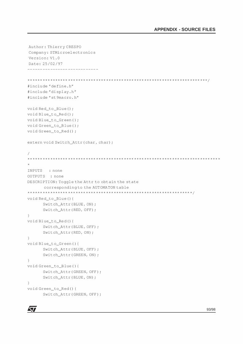
93/98
APPENDIX - SOURCE FILES
Author: Thierry CRESPO
Company: STMicroelectronics
Version: V1.0
Date: 25/02/97
---------------- ------------
**************** *******************************************************/
#include ”define.h”
#include ”display.h”
#include ”st9macro.h”
void Red_to_Blue();
void Blue_to_Red();
void Blue_to_Green();
void Green_to_Blue();
void Green_to_Red();
extern void Switch_Attr(char, char);
/
**************** ************************************************************
*
INPUTS : none
OUTPUTS : none
DESCRIPTION: Toggle the Attr to obtain the state
corresponding to the AUTOMATON table
**************** *************************************************/
void Red_to_Blue(){
Switch_Attr(BLUE, ON);
Switch_Attr(RED, OFF);
}
void Blue_to_Red(){
Switch_Attr(BLUE, OFF);
Switch_Attr(RED, ON);
}
void Blue_to_Green(){
Switch_Attr(BLUE, OFF);
Switch_Attr(GREEN, ON);
}
void Green_to_Blue(){
Switch_Attr(GREEN, OFF);
Switch_Attr(BLUE, ON);
}
void Green_to_Red(){
Switch_Attr(GREEN, OFF);
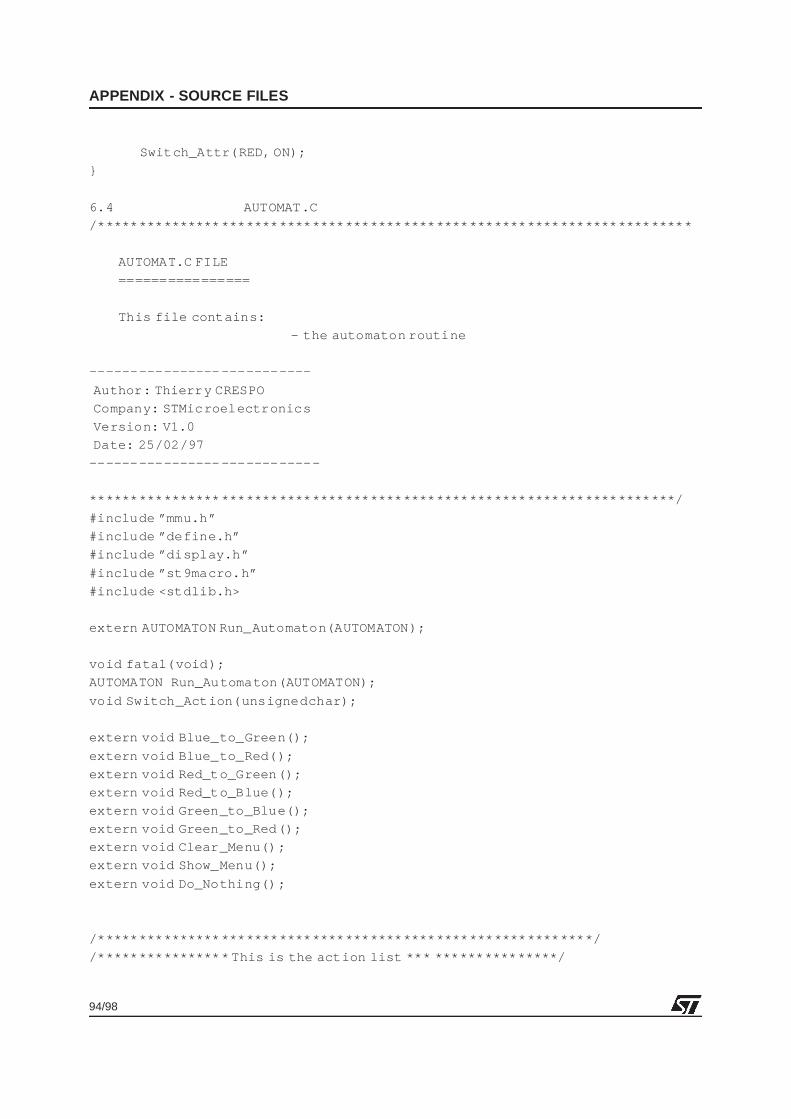
94/98
APPENDIX - SOURCE FILES
Switch_Attr(RED, ON);
}
6.4 AUTOMAT.C
/*************** *********************************************************
AUTOMAT.C FILE
================
This file contains:
- the automaton routine
---------------- -----------
Author: Thierry CRESPO
Company: STMicroelectronics
Version: V1.0
Date: 25/02/97
---------------- ------------
**************** *******************************************************/
#include ”mmu.h”
#include ”define.h”
#include ”display.h”
#include ”st9macro.h”
#include <stdlib.h>
extern AUTOMATON Run_Automaton(AUTOMATON);
void fatal(void);
AUTOMATON Run_Automaton(AUTOMATON);
void Switch_Action(unsignedchar);
extern void Blue_to_Green();
extern void Blue_to_Red();
extern void Red_to_Green();
extern void Red_to_Blue();
extern void Green_to_Blue();
extern void Green_to_Red();
extern void Clear_Menu();
extern void Show_Menu();
extern void Do_Nothing();
/*************** *********************************************/
/*************** * This is the action list *** ***************/
1
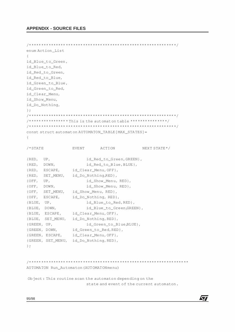
95/98
APPENDIX - SOURCE FILES
/*************** *********************************************/
enum Action_List
{
id_Blue_to_Green,
id_Blue_to_Red,
id_Red_to_Green,
id_Red_to_Blue,
id_Green_to_Blue ,
id_Green_to_Red,
id_Clear_Menu,
id_Show_Menu,
id_Do_Nothing,
};
/*************** *********************************************/
/*************** * This is the automaton table ***************/
/*************** *********************************************/
const struct automaton AUTOMATON_TABLE[MAX_STATES]=
{
/*STATE EVENT ACTION NEXT STATE*/
{RED, UP, id_Red_to_Green,GREEN},
{RED, DOWN, id_Red_to_Blue,BLUE},
{RED, ESCAPE, id_Clear_Menu,OFF},
{RED, SET_MENU, id_Do_Nothing, RED},
{OFF, UP, id_Show_Menu, RED},
{OFF, DOWN, id_Show_Menu, RED},
{OFF, SET_MENU, id_Show_Menu, RED},
{OFF, ESCAPE, id_Do_Nothing, RED},
{BLUE, UP, id_Blue_to_Red,RED},
{BLUE, DOWN, id_Blue_to_Green, GREEN},
{BLUE, ESCAPE, id_Clear_Menu,OFF},
{BLUE, SET_MENU, id_Do_Nothing,RED},
{GREEN, UP, id_Green_to_Blue, BLUE},
{GREEN, DOWN, id_Green_to_Red,RED},
{GREEN, ESCAPE, id_Clear_Menu,OFF},
{GREEN, SET_MENU, id_Do_Nothing,RED},
};
/*************** **************************************************
AUTOMATON Run_Automaton(AUTOMATONmenu)
Object: This routine scan the automaton depending on the
state and event of the current automaton.
1
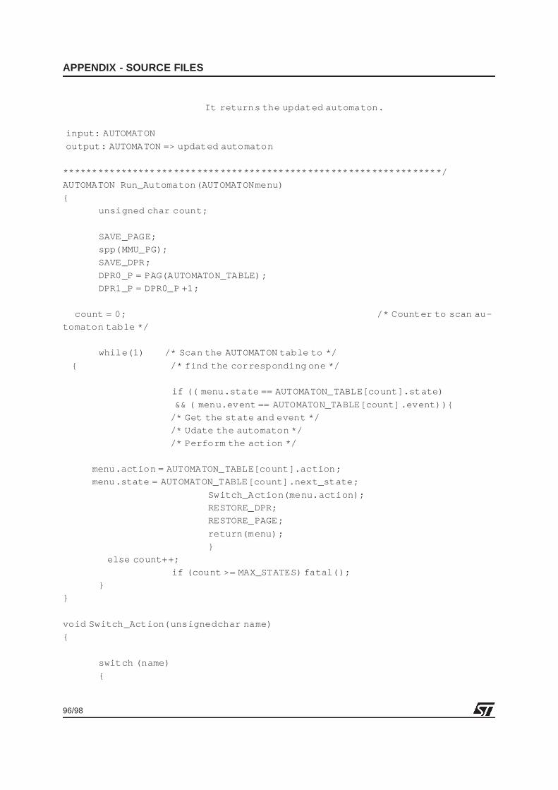
96/98
APPENDIX - SOURCE FILES
It returns the updated automaton.
input: AUTOMATON
output: AUTOMATON => updated automaton
**************** *************************************************/
AUTOMATON Run_Automaton(AUTOMATONmenu)
{
unsigned char count;
SAVE_PAGE;
spp(MMU_PG);
SAVE_DPR;
DPR0_P = PAG(AUTOMATON_TABLE);
DPR1_P = DPR0_P +1;
count = 0; /* Counter to scan au-
tomaton table */
while(1) /* Scan the AUTOMATON table to */
{ /* find the corresponding one */
if (( menu.state == AUTOMATON_TABLE[count].state)
&& ( menu.event == AUTOMATON_TABLE[count] .event)){
/* Get the state and event */
/* Udate the automaton */
/* Perform the action */
menu.action = AUTOMATON_TABLE[count].action;
menu.state = AUTOMATON_TABLE[count].next_state;
Switch_Action(menu.action);
RESTORE_DPR;
RESTORE_PAGE;
return(menu);
}
else count++;
if (count >= MAX_STATES) fatal();
}
}
void Switch_Action(unsignedchar name)
{
switch (name)
{
1
97/98
APPENDIX - SOURCE FILES
case id_Blue_to_Green:Blue_to_Green();break;
case id_Blue_to_Red:Blue_to_Red();break;
case id_Red_to_Green:Red_to_Green(); break;
case id_Red_to_Blue: Red_to_Blue();break;
case id_Green_to_Blue: Green_to_Blue();break;
case id_Green_to_Red:Green_to_Red();break;
case id_Clear_Menu :Clear_Menu();break;
case id_Show_Menu:Show_Menu();break;
case id_Do_Nothing:Do_Nothing();break;
default: fatal(); break;
}
}
void Do_Nothing(void)
{
}
void fatal(void)
{
while(1);
}
1
98/98
APPENDIX - SOURCE FILES
THE PRESENT NOTE WHICH IS FOR GUIDANCE ONLY AIMS AT PROVIDING CUSTOMERS WITH INFORMATIONREGARDING THEIR PRODUCTS IN ORDER FOR THEM TO SAVE TIME. AS A RESULT, STMICROELECTRONICSSHALL NOT BE HELD LIABLE FOR ANY DIRECT, INDIRECT OR CONSEQUENTIAL DAMAGES WITH RESPECT TOANY CLAIMS ARISING FROM THE CONTENT OF SUCH A NOTE AND/OR THE USE MADE BY CUSTOMERS OFTHE INFORMATION CONTAINED HEREIN IN CONNEXION WITH THEIR PRODUCTS.
Information furnished is believed to be accurate and reliable. However, STMicroelectronics assumes no responsibility for the consequencesof use of such information nor for any infringement of patents or other rights of third parties which may result from its use. No license is grantedby implication or otherwise under any patent or patent rights of STMicroelectronics. Specifications mentioned in this publication are subjectto change without notice. This publication supersedes and replaces all information previously supplied. STMicroelectronics products are notauthorized for use as critical components in life support devices or systems without the express written approval of STMicroelectronics.
The ST logo is a registered trademark of STMicroelectronics
1998 STMicroelectronics - All Rights Reserved.
Purchase of I2C Components by STMicroelectronics conveys a license under the Philips I2C Patent. Rights to use these components in anI2C system is granted provided that the system conforms to the I2C Standard Specification as defined by Philips.
STMicroelectronics Group of CompaniesAustralia - Brazil - Canada - China - France - Germany - Italy - Japan - Korea - Malaysia - Malta - Mexico - Morocco - The Netherlands -
Singapore - Spain - Sweden - Switzerland - Taiwan - Thailand - United Kingdom - U.S.A.
http:/ /www.st.com
1