Embed Size (px)
Citation preview
Stability Analysis of Autopilot Systems For Ballistic Missile Using MATLAB
A.J.ARUN JEYA PRAKASH#
Assistant Professor Department of Aerospace Engineering, University of Petroleum and Energy Studies,
Dehradun, Uttrakhand 248007, India. [email protected]
M. RAJA
Assistant Professor Department of Aerospace Engineering, University of Petroleum and Energy Studies,
Dehradun, Uttrakhand 248007, India. [email protected]
SHIKHA GUPTA
B. Tech Avionics Final Year Students Department of Aerospace Engineering, University of Petroleum and Energy Studies,
Dehradun, Uttrakhand 248007, India. [email protected]
SOORYA KUMAR
B. Tech Avionics Final Year Students Department of Aerospace Engineering, University of Petroleum and Energy Studies,
Dehradun, Uttrakhand 248007, India. [email protected]
YADVENDER SINGH DHILLON
B. Tech Avionics Final Year Students Department of Aerospace Engineering, University of Petroleum and Energy Studies,
Dehradun, Uttrakhand 248007, India. [email protected]
Abstract
This paper deals with the modelling and stability analysis of the Automatic Flight Control systems for a Ballistic Missile using Matlab. The Root Locus Analysis of the System is programmed in Matlab for four different transfer functions corresponding to different Aerodynamic Coefficients for the Vanguard Missile. The Paper includes two configurations of the missile Autopilot system one with Lead Compensator and without it. A comparison of these configurations has been done for the Missile autopilot system.
Keywords: Ballistic Missile, Automatic Flight Control, Lead Compensator, Vanguard Missile.
1. Introduction
A ballistic missile is a missile that follows a sub-orbital ballistic trajectory with the objective of delivering one or more warheads to a predetermined target. The first Ballistic missile is popularly known as V2 rocket and is developed by Germany in 1930s and 1940s under the supervision of Wernher von Braun.
Around 30 nations around the globe have deployed operational ballistic missile. A ballistic missile trajectory consists of three parts: the powered flight portion, the free-flight portion which constitutes most of the flight time, and the re-entry phase where the missile re-enters the Earth's atmosphere. The ballistic missiles are launched in a way such that the planned trajectory of these maintains the missile at zero angle of attack. This is a trial by
Conference on Advances in Communication and Control Systems 2013 (CAC2S 2013)
© 2013. The authors - Published by Atlantis Press 327
programming the pitch attitude to yield a zero-g trajectory. This attempt assumes certain velocity profile which may or may not be realised due to the variation in fuel flow rate. This condition and the presence of gusts in atmosphere results in angle of attack that is not zero, however this angle is to be made small in order to avoid the excessive loading of the missile structure. And if the angle of attack happens to be more than zero, the lift vector that is attacking on centre of pressure will have an effect which is unstable therefore it is a major control system problem for the missile. To maintain the stability of the missile along the longitudinal axis Lead Compensators are used in the control system design. The lead compensation improves the speed of the response and also reduces the amount of the overshoot by increasing the bandwidth. Lead compensation appreciably improves the transient response, whereas there is small change steady state accuracy. It is generally provided to make an unstable system stable.
2. Roll stabilisation:
Roll stabilisation can be accomplished by different means depending on the kind of missile. In General Ballistic missile, rolling moment can be achieved by differential swivelling of rockets mounted sideways of the missile. The successive task is the detection and estimation of rolling motion so that it can be controlled, and reduction of roll rate to zero or to maintain the roll angle equal to some specified reference. The use of a gyro would not be ample unless it was desirable only to reduce the roll rate considerably .The usage of roll rate gyro would result in type 0 system, which would result in extra steady–state error in roll rate in the presence of a constant disturbing rolling moment. To maintain a desirable roll angle, some kind attitude reference must be used. The vertical gyro is used for air –to-air or surface –to-air missiles. In both cases the feedback would be a signal proportional to the roll angle about longitudinal axis of missile. The other possible method is the usage of an integrating gyro with its input axis aligned along the longitudinal axis of the missile. Figure 1 is the block diagram of the roll stabilization control system .the servo can be represented by first-order time lag or a second –order
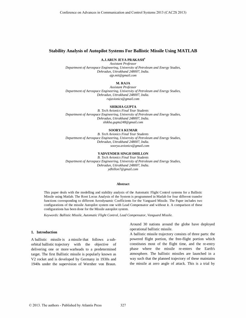
system. The transfer function of the missile for δa input to roll angle output can be represented as:
(1)
Fig.1. General Block Diagram of a roll stabilisation system
Where is the rolling moment produced by the aerodynamic controls or the reaction control divided by Sqd , and d is the diameter of the missile .the reference Area, S, is taken as the cross sectional area of the missile . In ballastic missile is due to aerodynamic
friction and therefore can be neglected, and thus the need for the lead network is explained by drawing the root locus of the system for the worst condition, that is =0. Without the lead circuit the two poles at origin
would move directly into the right half plane and thus the effect of the lead circuit is evident. If is not zero,
the transfer function of the missile consists of a pole at origin and a pole at s=-1/τ = (Sqd2/2uix) =. The
larger , the larger 1/τ, and the less are the
requirement for the lead circuit.
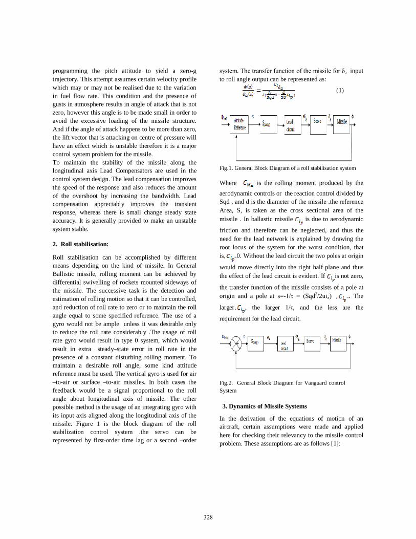
Fig.2. General Block Diagram for Vanguard control System
3. Dynamics of Missile Systems
In the derivation of the equations of motion of an aircraft, certain assumptions were made and applied here for checking their relevancy to the missile control problem. These assumptions are as follows [1]:
+ -
328
1. The X and Z axes are aligned in the plane of symmetry, and at the centre of gravity of the missile the origin of the axis system is located. 2. The mass of missile is constant. 3. The missile is a rigid body. 4. The earth is an inertial reference 5. The perturbations from equilibrium are small. All the assumptions are valid. Although the missile is consuming fuel at a high rate, if the instantaneous mass is used, the mass may be consumed constant during the period of analysis. Generally, the ballistic missile is not considered as a rigid body; but, in this analysis the missile is analyzed as a rigid body. The assumption that the earth is an inertial reference is adequate for the analysis of the control system. The assumptions of small disorientations for ballistic missile are even more valid as the disorientations are assumed small, and because the duration of the disturbance is less, so during the period of the dynamic analysis the velocity can be assumed constant. Therefore, for the longitudinal analysis the equations for the short –period approximation of the aircraft can be used. The equations are as follows:
(2)
(3)
Where c is replaced by d, the missile’s diameter. The time lag for the downwash created by the wing to reach the tail results in the generation of for the airplane. As in case of missile there is neither a wing nor a horizontal stabilizer so will be equal to zero. The actuating signal δ is the deflection of the thrust chamber, with the same sign convention as war used for the conventional aircraft. The thrust component is normal to the X axis an is proportional to sinδ; but, if δ is small, then sinδ can be replaced by δ in radians.
4. Calculations
The following calculations are illustrated below for finding the transfer functions:
Table1. Aerodynamic Coefficients for Vanguard Missile [1]
Case I:
Substituting the values for T=48 sec from the Table no.1 in equation 1 and 2, we get (99.75s +3.08) α(s) + (-99.75s +2.186) (s) = - 8.69 (s) (4) -10.55α {s) + (9.77s2 +0.683s) (s) =-60.83 (s) (5)
Then the transfer function for input to output is:
(6)
After cancelling the zero at 0.031 with the pole at 0.029, in case when we are using lead Compensator in our design: [T.F.] (Missile) [δ;θ] = (7)
Table2. Transfer functions with and without Lead Compensator
T(sec) H (ft) V (ft/sec)
M Q (lb/ft2)
m (slug)
Θ (deg)
Cma Cza Sec * Cmδ Czδ
48 12,200 604 0.57 300 547 81.7 10.55 -3.08 -.683 -60.83 -8.69
75 36,000 1285 1.26 585 445 68.5 11.27 -3.13 -.321 -34.25 -4.63 100.4 76,000 2400 2.41 300 354 57.2 16.59 -2.88 -.172 -70.15 -9.17
139* 185,000 5600 5.02 12 218 46.5 8.32 -2.3 -.0736 -2140 -229
329
5. Results
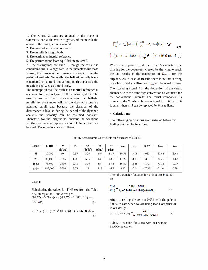
1. The Root locus the system where lead compensator is implemented can be represented as the give below for various times after the launch of the missile: Case1: Settling Time= 3.122 sec Peak Response= 28.9% Damping Ratio= 0.414 Gain( ωn ) = 51.7
Fig.3. Root locus plot for the missile system 48 sec after the launch, with damping ratio 0.414.
Case 2: Settling Time = 3.122 sec Peak Response =10.5% Damping Ratio= 0.416 Gain( ωn ) = 51.6
Case 3: Settling Time = 1.81 sec Peak Response= 16.3% Damping Ratio= 0.418 Gain( ωn ) = 4.74
Case 4: Settling Time =2.24 sec Peak Response= 29.4% Damping Ratio= 0.415 Gain( ωn ) = 4.86
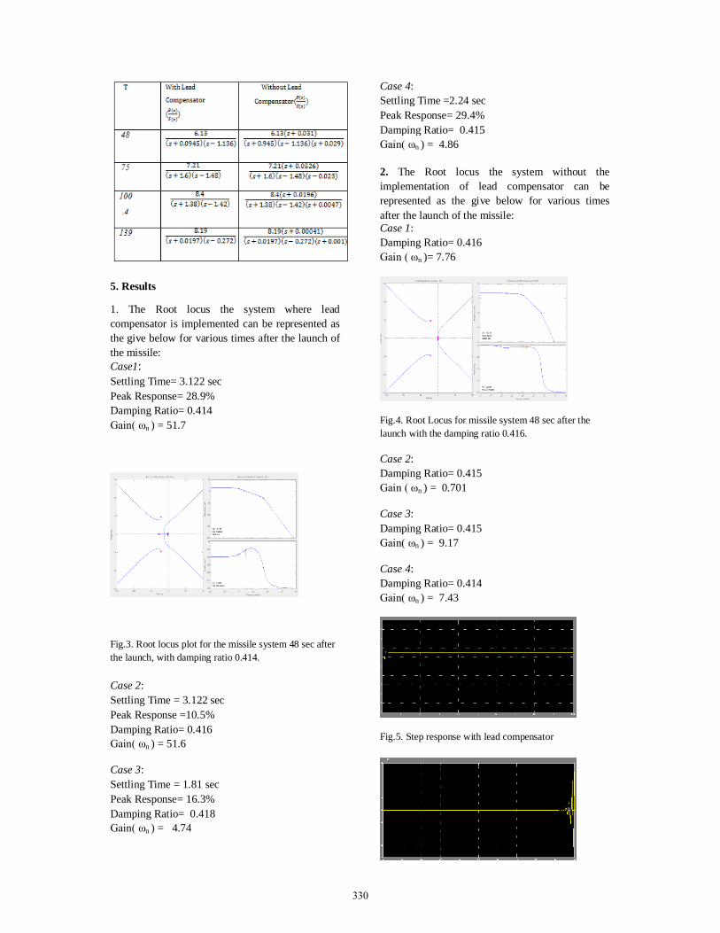
2. The Root locus the system without the implementation of lead compensator can be represented as the give below for various times after the launch of the missile: Case 1: Damping Ratio= 0.416 Gain ( ωn )= 7.76
Fig.4. Root Locus for missile system 48 sec after the launch with the damping ratio 0.416.
Case 2: Damping Ratio= 0.415 Gain ( ωn ) = 0.701
Case 3: Damping Ratio= 0.415 Gain( ωn ) = 9.17
Case 4: Damping Ratio= 0.414 Gain( ωn ) = 7.43
Fig.5. Step response with lead compensator
330
References
1. Blakelock J. H., “Automatic control of Aircraft and Missiles,” 2nd ed., (John Wiley & Sons, 1991).
2. Nelson R. C., “Flight Stability and Automatic Control,” 2nd ed.(McGraw-Hill, 1998).
3. P. Zarchan, Tactical and Strategic Missile Guidance,( AIAA, Reston, VA, 1997)
4. N.J. Danis, Space based tactical ballistic missile launch parameter estimation, (IEEE Transactions on Aerospace and Electronic Systems 29 (2) 1993) pp 412–424.
5. R.R. Bate, D.D. Mueller, J.E. White, Fundamentals of Astrodynamics, (Dover Publications, Inc., New York, 1971).
Fig.6. Step response without lead compensator
6. Conclusions
The Stability analysis of the missile autopilot system using Matlab is done successfully. Also the need of the Lead Compensator in missile autopilot system is proved successfully and it can be concluded that the lead compensator in case of missile autopilot system makes the system stable about longitudinal axis.
331