Embed Size (px)
Citation preview

Stability, Performance & Control for a Wing in Ground Vehicle
Submitted by: Quah Yong Seng, Jonathan
Department of Mechanical Engineering
In partial fulfillment of the requirements for the Degree of Bachelor of Engineering National University of Singapore
Session 2004 / 2005

Abstract This project was done in collaboration with Wigetworks Pte Ltd. It encompasses a
multidisciplinary effort to design, build and perform ground testing of an actual ground
effect craft.
This project successfully demonstrated the capabilities of a multidisciplinary approach in
designing, fabrication and ground testing of an operational WIG Craft. CFD was used in
conjunction with numerous flight tests to produce a working model.
The project begins with the study on the work done on WIGs to date; this is then
accompanied by the theoretical study on the flight mechanics of the WIG, as well as
aerodynamic theory to calculate the forces acting on the control surfaces. Equipped with
this knowledge, a control system utilizing Commercial-Off-The-Shelf (COTS) was
planned. Testing was done on the various components to determine their characteristics.
A ground effect craft was then designed built and flight-tested. The performance of the
craft was evaluated with the aid of on-board telemetry systems.
This project was done collaboration with Mr Ng Geok Hean, Mr Ng Yi Di, Benedict and
Mr Toh Boon Whye.
In Conclusion, the project has successfully demonstrated the capabilities of a Wing in
Ground craft and its immense potential in the field of high speed marine transport.
Finally the stability theory and test flight results were presented at the RSAF Aerospace
Technology Seminar 2005.
i

CAD model of the actual WIG Craft
Group Photo at the RSAF Aerospace Technology Seminar 2005
ii

Acknowledgements
The author wishes to thank God for his grace and wisdom to guide him to complete the
project.
The author wishes to thank the following persons for their various roles and the
invaluable aid in which they provided in the duration of the project.
• A/P Gerard Leng Siew Bing, Project Supervisor, for providing the necessary
guidance and invaluable advice throughout the course of the project.
• Wigetworks Pte Ltd for their industrial support.
• Mr Ng Geok Hean, for his help in the aerodynamic and CFD analysis.
• Mr Ng Yi Dyi, Benedict for his hard work and dedication in the construction of
the prototype craft.
• Mr Toh Boon Whye, for his hard work in the design and implementation of the
propulsion aspects of the craft.
• Dr Nikolai Kornev, Mr Graham Taylor and Mr Alexander Wolfensohn for their
technical advice in the field of Ekranoplans.
• Mr Ahmad Bin Kasa, Ms Amy Chee, Ms Priscilla Lee and Mr Cheng Kok Seng,
Staff of the Dynamics & Vibration lab for their help and support during the
duration of the project.
iii

Table of Contents
Abstract i
Acknowledgements iii
List of Figures vi
List of Tables vii
List of Symbols viii
Chapter 1: Introduction
1.1 Project Objectives 1
1.2 Structure of Dissertation 2
Chapter 2: Literature Review
2.1 History of Wing in Ground Vehicle Stability and Control Issues 3
Chapter 3: WiG Craft Theory
3.1 WiG Craft Operating Modes 7
3.2 WiG Stability 8
3.3 Longitudinal Stability 9
3.4 Pitch Stability Criterion 9
3.5 Height Stability Criterion 9
3.6 Effects of Longitudinal Instability 10
3.7 Position of the C.G. 11
3.8 Lateral Stability 12
iv

Chapter 4: Characteristics of the Control System components
4.1 Design of Control Surfaces 13
4.2 Load Torque Due to Control Surfaces 13
4.3 Moment Generated due to Control Surfaces about Hinge Point 14
4.4 Control Surfaces 15
4.5 Servo Characteristics 15
4.5.1 Experiment Setup 16
4.5.2 Sampling Interval of the Tattletale 5F Data Logger 17
4.6 Relationship between monitored servo output vs. deflection 17
4.7 Relationship between monitored output with a step input 18
4.8 Summary of Servo Characteristics 21
4.9 Overall Block Diagram of the WIG Craft 22
Chapter 5: Determination of WIG Craft Configuration, C.G and Moment of
Inertia
5.1 Pitch & Height Stability Analysis 23
5.2 Control Systems 28
5.3 Determination of the C.G. Position 28
5.3.1 Determination of Longitudinal C.G. position 31
5.3.2 Determination of Lateral C.G position 31
5.3.3 Determination of Vertical C.G. position 32
5.4 Thrust Line Alignment 33
Chapter 6: Flight Tests and Performance Evaluation
6.1 Flight Tests on water and land 36
6.1.1 MPSH Ground Testing 36
6.1.2 Testing on Water Surface 36
v

6.2 Test Flight Photos 37
6.3 WIG Craft Performance Evaluation 38
6.3.1 Performance Evaluation Objectives 38
6.3.2 Evaluation of Flight Speed and Take Off Distance 38
6.3.3 Evaluating Cruising Height 39
6.4 WIG Craft Specifications and Performance Summary 41
Chapter 7: Project Conclusion and Recommendations for Further Study
7.1 Project Conclusion 42
7.2 Recommendations for Further Study 43
References 44
Appendix
vi

List of Figures
Figure Description Page No.
1 The KM “Caspian Sea Monster” 5
2 Typical aircraft aerodynamic center 8
3 The respective aerodynamic centers of height and pitch 10
4 Craft travels across the water. Notice the pitch up at the gap near
the leading edge of the wing.
10
4.1 Craft starts to pitch up, trying to transit from Ground Effect to get
airborne.
10
4.2 Craft tries to get airborne but it is designed to operate only in the
Ground Effect regime.
11
4.3 Unable to get airborne, it crashes back unto the water surface. 11
5 Futaba S3102 servo 15
6 Schematic of the experiment setup 16
7 Deflection measurement of servo 16
8 Tattletale data logger 16
9 Graph of monitored output vs. deflection angle 18
10 Monitored servo output with a step input 20
11 Overall Transfer Function of the WIG Craft 22
12 Design and testing procedures 23
13 Moment characteristics curves 27
14 Control systems block diagram 28
15 Experimental setup for determination of the C.G. position of the
craft
29
16 Experimental Setup of the C.G. Experiment 30
vii

17 Close up of the setup 30
18 Close view of the spring balance used to determine the applied
force.
30
19 Close up protractor angle captured by the optical camera. 30
20 Craft balancing on the lateral jig 32
21 Lateral C.G. test jig 32
22 Craft balancing on the longitudinal jig 33
23 Close-up denoting the position of the longitudinal C.G. position 33
24 Jig setup for alignment of the motor shafts 34
25 Mounting point for the PAR hinge 35
26 Jig setup for alignment of the motor shafts 35
27 Alignment of the motor shafts with the aid of a laser.
35
28 Point alignment of the motor shafts.
35
29 Test Flight Photos (MPSH Front View) 37
30 Test Flight Photos (MPSH Rear View) 37
31 Test Flight Photos (West Coast Pond testing ground Front view) 37
32 Test Flight Photos (West Coast Pond testing ground Rear View) 37
33 Speed sensor installation 38
34 Integrated telemetry systems 38
35 Plot of air speed vs. time 39
36 Undercarriage view of the setup 40
37 Division of string segments 40
38 Captured side view of string during flight 40
viii

39 Height approximation using basic trigonometry 40
ix

List of Tables
Table Description Page No.
1 Potential difference output vs. Servo angle deflection 17
2 Servo Output measured with Time 19
3 Summary of Servo Characteristics 21
4 Aerodynamic centers of pitch and height with x directed upstream
with reference to the leading edge of the wing of chord length c =
0.4m.
25
5 Aerodynamic centers of pitch x directed upstream of wing of
chord length c = 0.4m.
26
6 C.G experiment readings 31-32
7 WIG Craft Specifications and Performance Summary 41
x

List of Symbols
θ Pitch Angle
ρ Density
S Wing Span
c Wing Chord Length
α Servo Deflection Angle
M Moment
V Velocity
δ Angle of Deflection of Control Surface
U Free Stream Velocity
h Height
θ Pitch Angle (Russian Notation)
θmC Derivative of the Coefficient of Moment and Pitch Angle
0mC Y intercept of the Coefficient of Moment
LhC Derivative of the Coefficient of Lift with Height
θLC Derivative of the Coefficient of Lift with Pitch
mhC Derivative of the Coefficient of Moment with Height
θX Aerodynamic Center of Pitch
hX Aerodynamic Center of Height
pM Maximum Overshoot
st Settling Time
xi

rt Rise Time
ξ Damping Ratio
nω Natural Frequency
F Force
xii

xiii

Chapter 1: Introduction
1.1 Project Objectives
The following goals are to be achieved
• Literature study of Wing in Ground Vehicles dynamics and control.
• Analysis and experimental testing of the individual control systems.
• Longitudinal Stability Analysis of the WIG.
• Lateral Stability Analysis of the WIG.
• Longitudinal / Lateral Stability Experiments performed on the WIG.
• Integration and Testing of the Control System.
• Test Flight of the Prototype.
1

1.2 Structure of the Dissertation
This thesis is divided into 7 Chapters and they are organized as follows:
Chapter 2 – Literature Review on a short history of Ground Effect Vehicles Stability
and Control Issues.
Chapter 3 – Discusses the theoretical stability criterions for a WIG Craft. It includes
pitch and height stability criterions. It also discusses about the lateral safety aspects of
a WIG Craft.
Chapter 4 – Discusses the results obtained from experiments performed on individual
control components. This is necessary to allow successful integration of the control
system into the Ground Effect Craft.
Chapter 5 – Describes the stability analysis done on the craft. This section also
includes the experiments conducted to find the resultant C.G. of the craft, aligning the
motors’ thrust lines and locating the respective centers for height and pitch using
Fluent.
Chapter 6 – Discusses the actual flight tests and the performance evaluation.
Chapter 7 – Project Conclusion and Recommendations for further study.
2

Chapter 2: Literature Review
2.1 History of Wing in Ground Vehicle Stability and Control Issues
Wing in Ground (WIG) vehicles, or sometimes referred to as Ekranoplans have enormous
applications in several areas. These areas include cargo transportation, military operations
and even search and rescue. The main reason for the development of WIG craft is due to
the speed limitations of conventional marine craft. New generation marine craft are
always designed to be faster than their predecessors. Eventually Conventional
displacement monohulls could no longer keep up with the ever increasing requirements
for speed and multihulls and planning hulls were introduced. Higher speeds were
achieved with hydrofoils and air cushion vehicles. The practical maximum speed of all
marine craft mentioned so far lies around 100 km/h. The drawback for high speed marine
craft is the increased power requirement and fuel consumption. This was caused by
viscous drag due to water friction. The obvious solution was to minimize contact with the
water surface during cruise conditions. This approach works for hydrofoils and
hovercraft. Unfortunately, the speed of a hovercraft is bounded by the sea state and
longitudinal stability considerations and the speed of a hydrofoil by cavitations of the
foils.
Early experiments of ground effect vehicles were conducted using models and small
scaled prototypes. The best known inventor’s application for a surface effect vehicle
belongs to the Finnish engineer G. Kaario (1935). He built a craft which was shaped out
3

of a snow plane in the shape of a ski supported small elongation wing. Early tests showed
positive ground effect. However the project was halted as he could not solve the
instability problem. Similar works were carried out by the Swedish and American
engineers. However stability problems plagued their experiments and therefore could not
produce any practical prototypes. Little was known in about the control systems for early
ground effect vehicles. One may assume that they probably utilized primitive reversible
control systems with push pull cables.
In 1947, a Russian by the name of R.Alekseev made proposals on aerodynamic forces
acting on the motion of high speed craft near the surface. His proposals were based on
principles of provision of longitudinal and lateral stability near the surface.
It was through these principles that he was able to design and built the first workable
prototype of a WiG craft or Ekranoplan. First designs were based upon the tandem wing
which was later replaced by the more favorable “plane” type of configuration. This
resulted in the production of well-known Ekranoplans such as the “Lun”, the “Orlyonok”
and the most famous of them all the “KM” or “Korabl' Maket”, also known as the
Caspian Sea Monster. Weighting at a staggering 500 tons, this craft is capable of reaching
speeds of up to 500km/hr.
4

Fig.1: The KM “Caspian Sea Monster”
Stability was attained by the inclusion of an enormous tail. This aids in counteracting any
excessive unwanted moments. It provides longitudinal trim, stability and controllability.
Due to surface effect aerodynamics, the tail was mounted extremely high. Tail spans
were in the range of 40 - 50% in size.
Incorporating into this enormous aircraft was a system which provided controls for the
elevator, rudder, wing flaps and hinge nozzles. Utilizing boosted control systems for
several control elements. An automatic control system was used to solve the craft’s
damping and stabilizing of flight altitudes, pitch angle and speed. With longitudinal
stability issues due to ground effect, the WiG craft represents a non-linear, non-stationary
and multi dimensional control plant. Piloting a ground effect craft is still extremely
difficult, with the narrow margins for error. Due to these factors, the KM crashed and
sank under harsh conditions.
5

With the collapse of the Soviet Union, developing or maintaining big ekranoplans
became impossible for the Russians and the design bureaus started focusing on smaller
ekranoplans for non-military use.
The WIG was developed with the sole aim to overcome these barriers of marine
transportation. Recent examples of WIGs are the Amphistar (ATT-nn Corporation) and
the Hoverwing (Wigetworks Company).
Potential Benefits of WIGs
• WIG craft can fulfill the need for increased speed of marine transport and may
thus fill the gap between shipping and aviation.
• WIG boats achieve high speeds while still maintaining high efficiency, especially
when compared to other high speed marine craft.
• Due to the marine nature of WIG boats their operating cost are low as compared
to aircraft.
• The infrastructural requirements for WIG boats are very low, any existing port is
sufficient.
• Especially in a wavy sea the comfort level in cruise is very high as compared to
other high speed marine craft.
6

Chapter 3: WiG Craft Stability theory
3.1 WiG Operating Modes
WiGs Craft are capable of operating in three modes.
• Displacement mode
o In this mode, the craft behaves like an actual ship in water.
• PAR (Power Augmentation Ram)
o In this mode, the craft behaves like a hovercraft with a static cushion of air
being generated by the PAR motors. This mode is for amphibious landings
and taking off.
o In PAR mode, it also serves as an aid for the craft to take off. It generates
a lift force on the wing by injecting of a jet stream under the wing. This
causes the deceleration the flow as it flows under the wing, generating a
high pressure region according to Bernoulli’s theorem.
• Ground Effect Mode
o In this mode, the craft is supported by a dynamic cushion of air under
wing (not a static cushion as in PAR mode). Lift increases and Drag
decreases in this region, leading to a high L/D ratio.
7

3.2 WIG Stability
WIG stability is dealt in two main areas, longitudinal and lateral stability. In the
longitudinal aspect, the WIG craft is extremely sensitive to both height and pitch
variations. This is extremely different from their airborne counterparts who only require
pitch stability. Instability in the longitudinal aspect has caused numerous crashes in WIG
craft history.
In order to understand about flight stability, we must first go back to conventional
aerodynamics to define two crucial points in an aircraft lifting system.
In conventional aerodynamics, a point known as the aerodynamic center is define where
the moment acting on the body is independent of the angle of attack. However, in the
presence of ground effect, force and moment acting on the body changes with height.
Therefore for a WIG craft, there are two aerodynamic centers. The former, which is the
same as the aircraft aerodynamic centers, is known as the center of pitch . The latter
where the moment is independent of height is known as the center of height . These
two aerodynamic centers can be obtained by considering the Lift and Moment curve with
respect to angle of attack and with respect to height.
θx
hx
Fig.2: Typical aircraft aerodynamic center
8

3.3 Longitudinal stability
To satisfy stability in the longitudinal motions, WIG craft must fulfill not only pitch but
also height stability.
3.4 Pitch Stability Criterion
For pitch stability the both airplanes and WiG craft must meet the following criteria:
Cmα < 0 and Cm0 > 0 (1)
Where:
mC is the coefficient of moment of the entire craft and represented as
cSV
MCm2
21 ρ
=
αα ddC
C mm =
3.5 Height Stability Criterion
Linearized longitudinal equations of motion
We will assume that there is no variation in cruise speed. All qualities will be rendered as
non-dimensionless. The basic equations of perturbed uncontrolled motion of a WiG is
written as
hCdthdCC
dtdC
dtd
CdtdChC
dthdC
dthd
hh
hh
mmmm
LLLL
~~~~~
~~~ˆ~
2
2
2
2
+=−−
+=−−
&&
&&
θθθμ
θθμ
θθ
θθ
(2)
9

By Routh – Hurwitz Criteria, to secure height stability of a WIG, one must select a
configuration such that the center of height is located upstream of the center of pitch.
0>− θxxh (3)
Fig.3: The respective aerodynamic centers of height and pitch.
Where:
xα = Cmα/CLα (4)
xh = Cmh/CLh (5)
3.6 Effects of Longitudinal Instability
From observation, one will realize that for a WIG Craft, its instability cannot be resolved
just by shifting the position of the C.G. Below shows 4 video stills illustrating the
consequences of longitudinal Instability.
Fig.4: Craft travels across the water. Notice the pitch up at the gap near the leading edge
of the wing.
Fig.4.1: Craft starts to pitch up, trying to
transit from Ground Effect to get airborne.
10

Fig.4.2: Craft tries to get airborne but it is
designed to operate only in the Ground Effect regime.
Fig.4.3: Unable to get airborne, it crashes
back unto the water surface.
The reason for this “flip” or “pitch-up ” behaviour is due to the fact that the aerodynamic
center of pitch is located at the far aft at small ground clearances (GE Regime) . As the
WIG Craft increases in height, the aerodynamic of the craft moves forward. This occurs
when the craft is climbing out of GE regime, therefore causing the “flip”. This stability
problem can be resolved by installing a large horizontal tail.
3.7 Position of the C.G.
As noted in (3), instability cannot be resolved with the repositioning of the craft’s C.G..
However, the location of the C.G. is crucial for establishing acceptable longitudinal
stability. The derivative for pitch angle with speed can be shown to be:
θ
θ
θ
θXX
XCC
VV hl
l
−∂∂
−=∂∂ 2 (6)
11
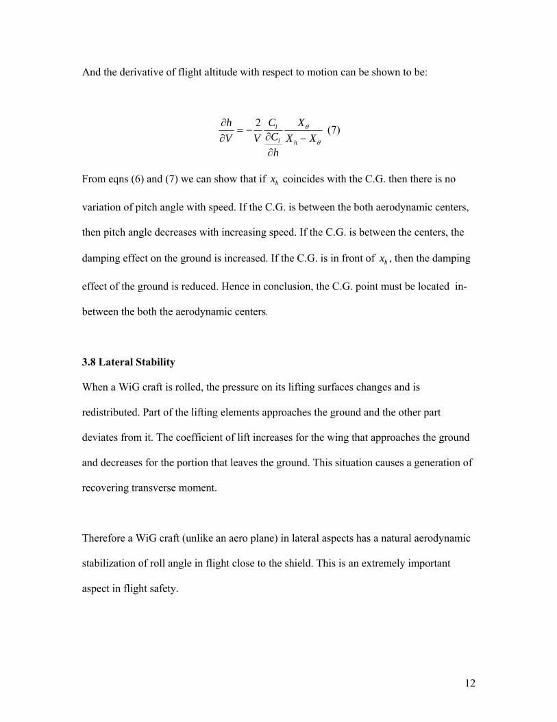
And the derivative of flight altitude with respect to motion can be shown to be:
θ
θ
XXX
hCC
VVh
hl
l
−∂∂
−=∂∂ 2 (7)
From eqns (6) and (7) we can show that if coincides with the C.G. then there is no
variation of pitch angle with speed. If the C.G. is between the both aerodynamic centers,
then pitch angle decreases with increasing speed. If the C.G. is between the centers, the
damping effect on the ground is increased. If the C.G. is in front of , then the damping
effect of the ground is reduced. Hence in conclusion, the C.G. point must be located in-
between the both the aerodynamic centers.
hx
hx
3.8 Lateral Stability
When a WiG craft is rolled, the pressure on its lifting surfaces changes and is
redistributed. Part of the lifting elements approaches the ground and the other part
deviates from it. The coefficient of lift increases for the wing that approaches the ground
and decreases for the portion that leaves the ground. This situation causes a generation of
recovering transverse moment.
Therefore a WiG craft (unlike an aero plane) in lateral aspects has a natural aerodynamic
stabilization of roll angle in flight close to the shield. This is an extremely important
aspect in flight safety.
12

Chapter 4: Characteristics of the Control System components
4.1 Design of control surfaces
The design of the control surfaces is extremely important as they control the directional
and longitudinal aspects of the craft. The aerodynamic forces acting on the control
surfaces due to deflection need to be overcome by the actuating motion of the servos.
Hence it is necessary to determine the load torque acting on the servos due to
aerodynamic forces acting on the control surfaces. The servo’s actuating torque must be
well above the load torque.
4.2 Determining load torque on the control surfaces
To carry out the analysis of torque on the control surfaces, thin aerofoil theory is used.
This is because in thin aerofoil theory, the lift and moment coefficients will always be
overestimated compared to a finite wing. Therefore it provides an effective method to
help ensure that the actual load torque is always less than the required torque generated
by the actuating motions of the servo.
4.3 Determining the moment generated by the control surface about hinge point
Using thin airfoil theory and the moment about the hinge point:
∫ ∑ ⎥⎦⎤
⎢⎣⎡ −−+
+−=
∞
=∞∞
π
θ
θθθθθθρ
hinge
dcccnAAcUM hingen
nle cos22
)sinsin
cos1(sin1
02 (6)
Where: ∫−=π
θπ
α0
01 d
dxdzA & ∫=
π
θθπ 0
cos2 dndxdzAn
13

Assuming that the control surface is a straight flap, dxdz is constant, and therefore this
leads to δtan−=dxdz
Where: δ denotes the angle of deflection of the control surface. With this implies = 0
and the equation is reduced to:
nA
∫ ⎥⎦⎤
⎢⎣⎡ −−
+−= ∞∞
π
θ
θθθθθρ
hinge
dcccAcUM hingele cos22
)sin
cos1(sin 02 (7)
Solving yields
⎥⎦⎤
⎢⎣⎡ −−−+−= ∞∞ hingehingehingehingehingehingehinge
cccccccAUM θθθπρ 2sin8
sin)2
()2
(02 (8)
According to CFD calculations and thrust experiments performed by Mr Ng Geok Hean
and Mr Toh Boon Whye, and smU /15=∞ rad18020πα = .
Due to the fact that the maximum deflection a servo can achieve was 50 degrees in both
directions, hence the maximum value was set to be rad18050πα = .
Hence and mc 09.0= mchinge 03.0=
Solving yields NmM hinge 16.0=
14

4.4 Control surfaces
The craft has two control surfaces, namely the rudder for directional control and the PAR
arm for the vectoring of thrust. The reason for excluding flaps and ailerons is due to the
fact that a WIG Craft has natural lateral stability; hence it is able to execute a nose level
turn without the aid of extra control surfaces.
In order to determine the transfer function of the entire control system of the craft, we
need to find out the characteristics of the various components.
4.5 Servo Characteristics
The Futaba S3102 servo shown was selected due to it’s high torque and its minimal
weight. It is able to output a torque of 0.37Nm and it weights 21g. In order to determine
the transfer function of the servo, an experiment was setup to find out the relationship
between the deflections of the servo with the output of the servo.
Fig. 5: Futaba S3102 servo
15

4.5.1 Experiment Setup
The experiment setup is shown below.
Fig. 6: Schematic of the experiment setup
Fig. 7: Deflection measurement of servo
Fig. 8: Tattletale data logger
The first part of the experiment is to verify the output of the servo with the deflection
angle. This is to verify that a linear relationship exists. The second part of the experiment
is to study the output of the servo under a unit step input signal.
16

4.5.2 Sampling Interval of the Tattletale 5F data logger
The Tattletale 5F data logger was programmed in TXBASIC language. The sampling
intervals were set to 10ms to provide a more accurate transient response of the S3102
servo. The TXBASIC program is shown in the appendix.
4.6 Relationship between monitored servo output vs. deflection
For this part of the experiment, the receiver will send various signals to the servo to
position itself at several angles. From the setup shown above, the servo is connected to a
potentiometer and a protractor is positioned at the center of the servo. As the servo is
rotated to several angles, the potential difference across the potentiometer is measured
and at the same time the deflection angle is measured.
Table 1: Potential difference output vs. Servo angle deflection
Deflection
Angle (º) -40 -30 -20 -10 0 10 20 30 40
Monitored
Output 0.01311 0.01204 0.0107 0.00856 0.00707 0.00451 0.00261 0.00107 0
17

Servo Output vs Deflection Angle
-0.002
0
0.002
0.004
0.006
0.008
0.01
0.012
0.014
0.016
-50 -40 -30 -20 -10 0 10 20 30 40 50
Servo Output
Def
lect
ion
Ang
le
Fig. 9: Graph of monitored output vs. deflection angle
From the graph we can deuce that there exists a linear relationship between the monitored
output and angular deflection. Next we will use a step input to determine the output of the
servo.
4.7 Relationship between monitored output with a step input
In the second part of the experiment, a step input will be sent to the servo and the output
characteristics will be determined. The experiment setup will be the same as in the first
part. The receiver will receive a step input from the transmitter and sent it to the S3102
servo. The output response will be detected by the data logger.
18

A BASIC program was written to enable the data logger was programmed to read the
output of the servo response every 10ms. The response of the servo is then obtained by
plotting the output signal vs. time.
Table 2: Servo Output measured with Time
Time
(ms)
10 20 30 40 50 60 70
Measured
Output
0
0.004116
0.032921
0.123458
0.271603
0.460905
0.621399
Time
(ms)
80 90 100 110 120 130 140
Measured
Output
0.798354
0.930043
1.0000
1.0000 1.0000 1.0000 1.0000
19

Measured Servo Output vs Time
0
0.2
0.4
0.6
0.8
1
1.2
10ms 20ms 30ms 40ms 50ms 60ms 70ms 80ms 90ms 100ms 110ms 120ms 130ms 140ms
Time (ms)
Am
phitu
de
Fig. 10: Monitored servo output with step input
Most real life elements can be modeled using a 2nd order system. Hence the S3102 servo
can be modeled as a 2nd order system with settling time ( ), rise time ( ) and maximum
overshoot ( ). Hence giving the servo it’s system characteristic.
st rt
pM
Rise time is defined as the time required for the response to rise from 5% to 95%. Settling
time is the time required for the response to remain within a range of 3 – 5% of the final
value.
From the graph, we can observe that the servo characteristic shows no overshoot and this
implies that the system is not an under damped system where ξ < 1. Hence the servo
system can be modeled approximately by:
20

tt nn eetc ωξξωξξ
ξξξξξξ)1(
22
)1(
22
22
)1(121
)1(1211)( −−−−+−
−−−−
−+−+= (9)
Since with the assumption that the system is a 2nd order system, and assuming that it is a
critically damped system where ξ = 1. The equation is reduced to:
)1(1)( tetc ntn ωω +−= − (10)
The value of nω can be determined from the servo output as (045.01
=nω ) which can be
obtained from Figure 9 with 25.0
1tn =ω where corresponds to the 0.25 of the
amphitude. Hence the servo transfer function can be approximated by a 2
25.0t
nd order system
given by 2
2
)()(
n
nServo s
sGωω+
= where nω is 22.22.
4.8 Summary of servo characteristics
System
Characteristics
Values
st 2% 0.18s
rt 0.095s
nω 22.22
ξ 1 (Approximated)
21

4.9 Overall Block Diagram of the WIG Craft
WIGsG )(
)(sDExternal
ControllersG )(
2
2
)()(
n
nServo s
sGωω+
=
Fig. 11: Overall Transfer Function of the WIG Craft
Figure 11 shows the overall transfer function of the WIG Craft subjected to an external
disturbance . It is to be noted that the and the were not
determined in the course of this project. Assuming that the reference signal is 0, the
transfer function between angular displacement
)(SDExternal WIGSG )( ControllerSG )(
)(SI
)(Sθ and external disturbances
is given by:
)(SDExternal
ControllerWIGServoExternal sGsGsGsDs
)()()(11
)()(
+=
θ
Therefore the steady state output by a step input is given by:
ssGsGsGsss
ControllerWIGServosStatesteady
1)()()(1
)(lim 0 +== →− θθ
22

Chapter 5: Design of the WIG Craft
5.1 Pitch & Height Stability Analysis
As stated in WIG theory, a craft must have stability in terms of pitch and height. CFD
software was used to aid in determining whether is the design is feasible in terms of
stability. Following CFD analysis, a test model was built and tested to determine if the
configuration is suitable for actual production of an actual craft.
CFD Analysis using Fluent
Construct and test the prototype
Construct the actual craft and conduct trials
Modifications and Fine tuning
Pass stability and aerodynamics requirements?
Able to Maintain course?
Aerodynamics ok?Easy to control?
A working WIG craft
Design and Testing Flowchart
Fig. 12: Design and testing procedures
23

As stated in chapter 3, the criterion for attaining pitch stability requires:
Cmα < 0 and Cm0 > 0.
Where:
mC is the coefficient of moment of the entire craft and represented as
cSV
MCm2
21 ρ
=
αα ddC
C mm =
Criterion for height stability is stated in chapter 3.2 as:
0>− θxxh
To secure height stability of a WIG, one must select a configuration such that the center
of height is located upstream of the center of pitch.
CFD analysis was carried out using Fluent. Our objective was not a wing alone design.
Hence this requires comparing 3 combinations of moment curves. This analysis will only
allow us to determine pitch stability statically. In terms of dynamic stability, a test
platform is required to investigate whether the configuration has sufficient dynamic
stability.
In order to determine a statically stable configuration, CFD analysis was done in
collaboration with Mr Ng Geok Hean. The wing size was determined for the specific
payload of 2kg. With that moment curves were plotted with results obtained from CFD.
24

With the wing size determined, CFD analysis is further applied to the WIG craft with
both wing and fuselage integrated. The aerodynamic characteristic curves are also obtain
in this case which will be use to determine the C.G position for static stability
requirement. There was a slight deviation from the curves obtain by the wing alone is due
to two reasons. One is the interference of the flow between the fuselage and the wing.
Second is the wing is position at the middle of the fuselage which makes the relative
height between the wing to the ground higher.
Table. 3. Aerodynamic centers of pitch and height with x directed upstream with
reference to the leading edge of the wing of chord length c = 0.4m.
xα xh
Wing -28.55% -32.112% Wing-Fuselage -29.2% -34.1%
As stated, the condition for stability for a WIG craft requires the center of height to be
located upstream of the center of pitch. However, from the results shown in Table 1, a
wing alone design will not be stable as the center of height will always be at the aft of
center of pitch. Hence a horizontal tail needs to be designed to provide the condition of
longitudinal stability by shifting the center of pitch downstream such that condition (1)
will be met. Also, by placing the horizontal tail high up such that it is out of ground
effect, the value of Cmh and CLh is theoretically unmodified therefore xh remains in the
same position. Therefore to achieve height & pitch stability, the Cmα value will have to
be modified in order to shift xα further down stream.
25

Table. 4. Aerodynamic centers of pitch x directed upstream of wing of chord length c =
0.4m.
Cmα at x/c = 0.3 xα with ref to x/c = 0.3 xα with ref to leading edge Wing-Fuselage 0.1854 1.90% -28.10%
Wing-Fuselage-Tail -1.1579 -30% -50%
Based on the condition given by equation (1), the horizontal tail has to be design to
ensure the pitching moment characteristic of the whole craft meet the requirements given
in (1). Therefore by fixing the C.G, the required moment characteristic for the tail can be
chosen. With the C.G position slightly aft (2cm) of the center of pitch, the moment
characteristic curve of the wings-fuselage configuration, Cmwf, were plotted (Refer to
appendix). From equation (4) the center of pitch is dependent on the value of Cmα, hence
in order to shift the center of pitch further downstream until condition (2) is met, the Cmα
of the entire craft is then chosen to meet the condition as shown in Table 2. From Lift
curve obtained from Mr Ng, the trimmed condition chosen at 3 degrees of angle of attack
since Mr Ng noticed flow separation was observed for angle of attack exceeding 5
degrees. With the trimmed angle fixed, Cm0 of the entire craft will also be determined.
Therefore with the moment characteristic curve of the entire craft, Cmwft, known, the tail
moment characteristic curve can be simply obtain by the following relation:
Cmwf + Cmt = Cmwft (11)
The moment characteristic curves of Cmwf, Cmt & Cmwft are all plotted in Fig. 11. With
Cmαt and Cm0t known from (11), the size and the incidence angle of the tail can be
determined by the two relationships respectively. Thus satisfying the pitch stability
criteria.
26

Fig. 13: Moment characteristic curves.
As for the height stability criteria, the moment curves were plotted with height and
varying of pitch for the entire craft. It was found that the center of height was
approximately at 10% of the chord and the center of pitch was at ¼ chord length,
fulfilling condition (3).
27

5.2 Control Systems
In view of the presence of water and the possibility of crashes occurring during sea trials,
the control system was kept simple and the components were waterproofed. This was to
ensure in the event of a crash occurring in water, the control systems can be salvageable
or rebuilt easily. The figure below shows the control flowchart of the control systems
which were described in chapter 4.
Fig. 14: Control systems block diagram
5.3 Determination of the C.G. of the Craft
Since during the design phase, the WIG craft was designed to have its C.G. at
approximately 2cm aft of the center of height as stated in section 5.1. The determination
of the C.G. was to ensure that the C.G position of the assembled WIG Craft in between
both the centers of height and pitch. This is to ensure that the craft’s stability behavior in
the longitudinal aspect will be similar to that of the moment curves obtained through
Fluent.
An experiment was setup to determine the position of the C.G. in the longitudinal
direction. The craft was mounted and hinged at point A and is allowed to rotate freely
about the X’Z’ plane for the determination of the longitudinal C.G point. Similarly the
28

craft was setup to determine the C.G. point for the lateral and vertical directions. The
angle of tilt was measured using a protractor mounted at point A. A force was applied at a
known position using a spring balance. The magnitude of the force was recorded and the
resultant angle was recorded. Hence the C.G. point was then obtained using sinple
trigonometry and by taking moment about hinge A. One must note that this experiment
setup is capable of measuring only 2 out of the 3 coordinates of the C.G. position. For a
measurement in the Y’Z’ plane, the craft was remounted and the similar procedure was
carried out.
Fig. 15: Experimental setup for determination the C.G. position of the craft.
29

Fig. 16: Experimental Setup of the C.G.
Experiment
Fig. 17: Close up of the setup
Fig. 18: Close view of the spring balance used to
determine the applied force.
Fig. 19: Close up protractor angle
captured by the optical camera.
30

5.3.1 Longitudinal C.G. Position F (Xapplied) = Mwig [x cos (αapplied)] X c.g. = x + Z c.g. tan (αapplied) X c.g. = Z c.g. / tan (αinitial)
X c.g.= applied) cos(]applied) tan()initial tan(1[ (Xapplied) F
ααα M−- Xhinge (12)
Xhinge=30.4cm, Mwig =1.494kg, αinitial =8º
F (N) Xapplied(cm) αapplied (º) X c.g. (cm)
5 42.0 71 47
9 42.5 56 33.5
Average 33.4
5.3.2 Lateral C.G. Position
F (Yapplied) =Mwig [y cos (θapplied)] Y c.g. = y + Z c.g. tan (θapplied) Y c.g. = Z c.g. / tan (θinitial)
31
Y c.g.= applied) cos(]applied) tan()initial tan(1[ θθθ M−B
(Yapplied) F - Yhinge (13)

Yhinge=1.5cm, Mwig =1.377, θinitial = 5º
F (N) Yapplied(cm) θapplied (º) Y c.g. (cm)
5 29.4 74 55.3
6.5 30.6 70 55.1
Average 55.2
5.3.3 Vertical C.G. Position
Z c.g.= Y c.g. tan (θinitial)
Z c.g.= 33.4 tan 8º = 4.69 cm
To verify that the above results are correct, 2 jigs were designed to test if the craft was
able to balance at the appropriate C.G. point. The two jigs and how they are used to
verify the C.G. position is showed below. On a lateral basis, the craft was able to balance
itself on a 6mm carbon rod. For a longitudinal basis, Tests conducted using them showed
that the craft’s C.G. located at approximately that region.
Fig. 20: Craft balancing on the lateral jig Fig. 21: Lateral C.G. test jig
32

Fig. 22: Craft balancing on the longitudinal
jig
Fig. 23: Close-up denoting the position of
the longitudinal C.G. position
5.4 Thrust line Alignment
Another important factor that is to be taken into account is the alignment of the thrust
line. Since the WIG Craft is propelled by 3 engines, it is imperative that we ensure all
three engines are “inline” with each other. If not, the craft may exhibit tendencies to drift
and even turn when one requires the craft to travel in a straight line.
Another jig was constructed primary to ensure that all the motors shafts are mounted at
equal distances from each other. There must not be any deviation between the distances
of the motors with respect to the fuselage. If this happens, there will be a moment which
will cause the craft to turn excessively. A reference point was needed to “fit” the Jig onto
the craft. This will create a datum from which the thrust lines can be determined with
reasonable accuracy. The side of the fuselage was chosen as the datum.
33

Three laser pointers were placed in the movable parts of the jig to determine how much
error there was in the distances between the front two motors. The rear motor was
referenced with the center point of the jig. Do note that the laser pointer mounted at the
center is fixed. A schematic of the jig is shown below. The red center lines denote the
placements of the laser pointers.
Fig. 24: Jig setup for alignment of the motor shafts.
With the aid of this jig, it reduced the error in the mounting positions of the front two
motors to approximately 0.05mm. Condition for accuracy is achieved when both laser
spots coincide onto each motor shaft and when the distance from the center to each motor
shaft is equal ±1mm. From this condition, the mounting point for the hinge was
determined.
34

Fig. 25: Mounting point for the PAR hinge.
Fig. 27: Alignment of the motor shafts
with the aid of a laser.
Fig. 26: Jig Setup for alignment of the motor shafts.
Fig. 28: Point alignment of the motor
shafts.
35

Chapter 6: Flight Tests and Performance Evaluation
6.1 Flight Tests on Water and Land
Flight Tests were conducted in 2 main areas, in the MPSH and the West Coast pond.
The MPSH was chosen as we needed to verify the performance of the craft; the MPSH
provides a controlled environment to test the craft, since CFD analyses were conducted
assuming a flat surface for ground effect. Also as an enclosed area, it is independent of
environmental variables such as weather and wind. The amphibious capabilities of the
craft can be tested on the grounds of the MPSH. Take off and speed of the craft can be
evaluated without any external disturbances.
The West Coast pond was chosen to test the marine capabilities of the craft.
6.1.1 MPSH Ground Testing
Flight Tests were conducted in the MPSH. Obstacles were cleared to ensure that the
safety of the craft. In PAR mode, the craft was able to lift off the ground after some
distance. The take off distance and airspeed were evaluated. Several videos were taken
and it was evident that the craft has achieved Ground Effect (GE), with the evidence of
an air gap just below the craft. Several runs showed that the craft was capable performing
a turning maneuver in GE.
6.1.2 Testing on Water Surface
Flight Tests were conducted at the West Coast Pond. Environmental variables included
wind and water waves due to a nearby fountain. Tests showed that the craft was able to
36

“un-stick” from the surface of the water after some distance. Similarly, the cruising speed
and the take off distance were evaluated. However we noticed that the distance of the air
gap between the water surface and the craft was not large as compared to the tests in the
MPSH. The main reason for this was due to the undulating surface of the water which
provided a diminished GE air cushion. Hence the decrease in thickness in the GE air
cushion.
6.2 Test Flight Photos
MPSH Testing Ground
Fig. 29: Front view
Fig. 30: Rear view
West Coast Pond Testing Ground
Fig. 31: Front view
Fig. 32: Rear view
37

6.3 WIG Craft Performance Evaluation
6.3.1 Performance Evaluation Objectives
The main purpose of this chapter is to determine the performance of the WIG Craft. The
performance variables that are to be determined are as follows:
• Flight Speed
• Take Off Distance
• Take Off Speed
• Cruising Height
6.3.2 Evaluating Flight Speed and Take Off Distance
A Telemetry system was installed onboard the craft to evaluate the flight speed. Results
were viewable via a handheld computer. The MPSH was chosen since it eliminates the
problems of water and environmental disturbances.
Fig. 33: Speed sensor installation
Fig. 34: Integrated telemetry systems
38
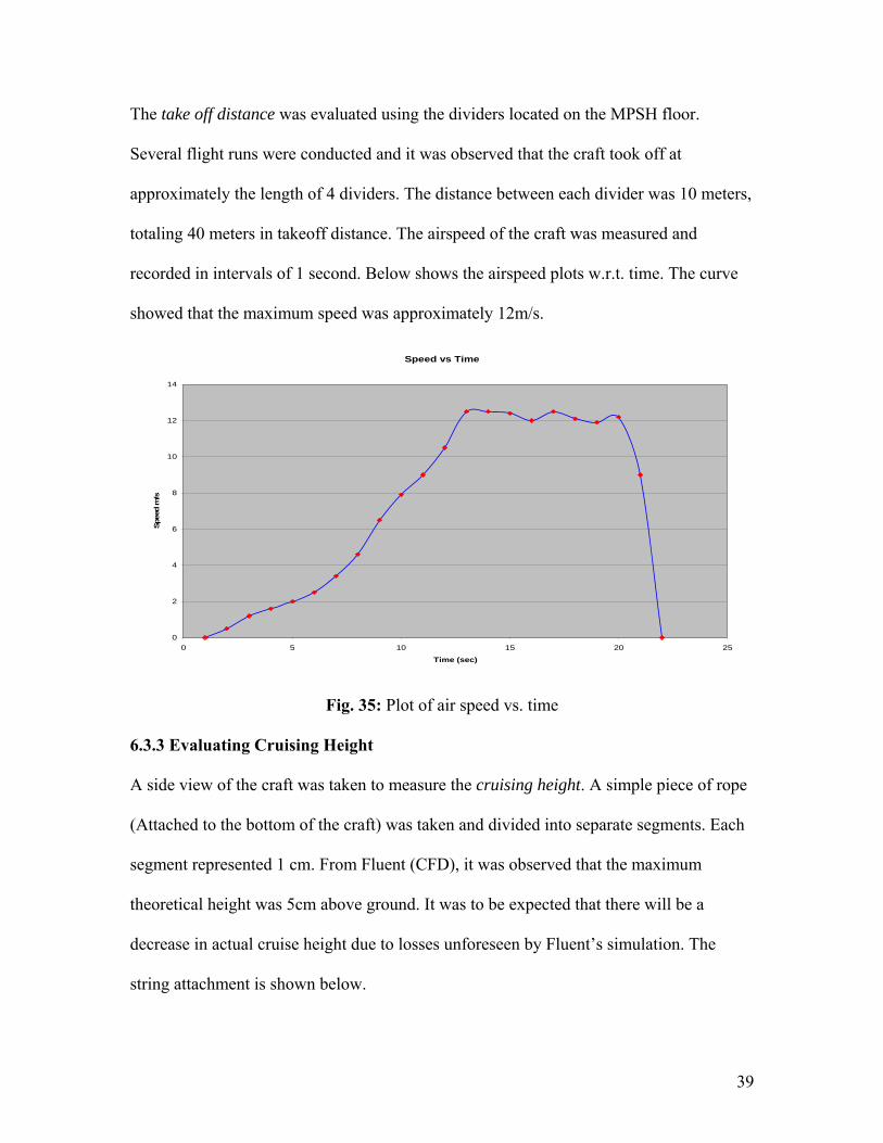
The take off distance was evaluated using the dividers located on the MPSH floor.
Several flight runs were conducted and it was observed that the craft took off at
approximately the length of 4 dividers. The distance between each divider was 10 meters,
totaling 40 meters in takeoff distance. The airspeed of the craft was measured and
recorded in intervals of 1 second. Below shows the airspeed plots w.r.t. time. The curve
showed that the maximum speed was approximately 12m/s.
Speed vs Time
0
2
4
6
8
10
12
14
0 5 10 15 20 25
Time (sec)
Spee
d m
/s
Fig. 35: Plot of air speed vs. time
6.3.3 Evaluating Cruising Height
A side view of the craft was taken to measure the cruising height. A simple piece of rope
(Attached to the bottom of the craft) was taken and divided into separate segments. Each
segment represented 1 cm. From Fluent (CFD), it was observed that the maximum
theoretical height was 5cm above ground. It was to be expected that there will be a
decrease in actual cruise height due to losses unforeseen by Fluent’s simulation. The
string attachment is shown below.
39

Fig. 36: Under view of the string setup. Fig. 37: Division of string segments
There will be errors like the verticality of the string, which may result in inaccuracy in
the readings. A flight test was conducted in the MPSH to verify the theoretical results
with actual flight test. A close up photo of the craft was captured while performing a
flight at the MPSH. The photos were captured using a 1/1000sec shutter speed. From the
marked divisions on the string and using basic trigonometry, we are able to approximate
the altitude of the vehicle.
Fig. 38: Captured side view of string during
flight.
Fig. 39: Height approximation using basic
trigonometry.
40

6.4 WIG Craft Specifications and Performance Summary
Take off Distance 40 meters
Cruising Height 0.04m
Take off Speed 9m/s (Estimated from Videos)
Maximum Speed Approx. 16m/s
Wing Span 1.1meters
Maximum Tested
Payload
1.5kg
Aspect Ratio 2.5
Chord Length 0.4m
Static Margin 15% Chord
Tail Wing Span 0.5m
Tail Chord Length 0.3m
41

Chapter 7: Project Conclusion and Recommendations for Further Study
7.1 Project Conclusion
From the drawing board to the building of the actual craft, this project required a
multidisciplinary approach in engineering and design fundamentals. The usage of
software to aid in the design and selection process has shown the effectiveness in cutting
down design time. Ensuring proper tolerance at critical points of the craft was aided with
jigs designed from scratch. Conducting field tests on prototypes and identifying key areas
of improvement allowed us to progress to the next design stage.
From this project, it was able to draw up a standard operating procedure for designing
and fabricating a working small scale Wing In Ground Craft. This SOP will aid WIG
Craft engineers to design and come up with a practical working prototype.
My achievements of the project are as follows:
• The WIG Craft designed was statically and dynamically stable for it to enter and
stay in the ground effect regime.
• The WIG craft was able to perform land and water-based take offs and
maneuvers.
• I have demonstrated the effectiveness of using of CFD to determine the stability
derivatives to perform a preliminary analysis of a WIG craft.
• Through a multidisciplinary approach and team effort we were able to design and
build, from scratch a small scale WIG craft which performed successfully during
actual field trials.
42

• It demonstrated the potential amphibious capabilities and speed of a small scale
WIG Craft.
• I designed three jigs for the determination and verification of the C.G. positions
and controlling of manufacturing errors.
• Field tests were conducted and experiments were performed using the TattleTale
5F data logger to determine the parameters of the small scale Wing In Ground
Craft.
• I provided a SOP for stability design of a small scale Wing In Ground Craft.
7.2 Recommendations for Further Study
Recommendations for further study includes designing and integrated UAV system for
the WIG Craft, experimenting with other forms of chord shapes for an improvement in
the ground effect phenomena and improving the design to include a 4th mode of
operation as an airborne aircraft in the event of undesirable sea states.
43

References
1. Robert C. Nelson: Flight Stability and Automatic Control 2nd edition McGraw Hill
2. Katsuhiko Ogata: Modern Control Engineering 3rd edition Prentic Hall
3. A. Maskalik, D. Sinitsyn: EKRANOPLANS Peculiarity of the theory and design
Sudostroyeniye,
4. A. Maskalik, D. Sinitsyn: Amphistar First Civilian Ekranoplan Sudostroyeniye,
5. H.H. Chun, C.H Chang, Longitudinal stability and dynamic motions of a small
passenger WIG craft, Ocean Engineering 29, 2002, pp 1145-1162
6. K.V. Rozhdestvensky, Aerodynamics of a Lifting System in Extreme Ground Effect, 1st
ed., Springer-Verlag, 2000
7. Historical Review of WIG vehicles Journal of Hydronautics vol 14 no 3 July 1980 pp
65-76
8. Feasibility Study of a Hybrid Airship Operating in Ground Effect Journal of Aircraft,
vol 14 no 8 Aug 1977 pp 809-815
9. Knud Benedict, Nikolai Kornev, Michael Meyer, Jost Ebert, Complex mathematical
model of the WIG motion including the take-off mode, Ocean Engineering 29, 2002, pp
315-357
10. Nikolai Kornev Konstantin Matveev Complex numerical modeling od dynamics and
crashes of Wing in Ground vehicles, AIAA 2003-600
44