Embed Size (px)
Citation preview
1
Gana A. J. & Tabat J. B.
CARD International Journal of Engineering and Emerging Scientific Discovery
ISSN: 2536-7250 (Print): 2536-7269 (Online)
Volume 2, Number 3, September 2017
http://www.casirmediapublishing.com
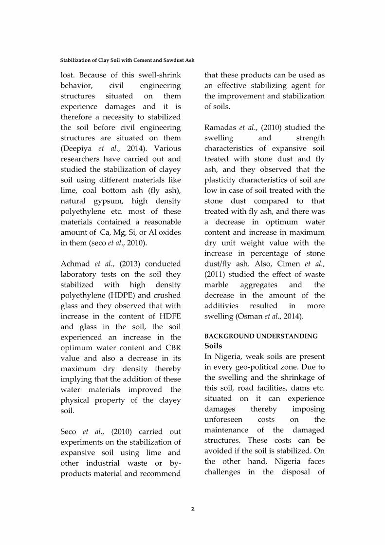
Stabilization of Clay Soil with Cement and Sawdust
Ash
Gana A. J. & Tabat J. B.
Department of Civil Engineering
College of Science and Engineering
Landmark University, Omu-Aran, Kwara State, Nigeria
Email: [email protected]; [email protected] Corresponding Author: Gana A. J.
ABSTRACT
One of the most pressing needs for research in geotechnical engineering is the issue
of the use of marginal soils for fills and as backfill material for walls and bridge
abutments. It is therefore essential to come up with more economical methods of
soils stabilization. Due to the poor disposal of sawdust in Nigeria, this study
investigated the possible effect of the addition of sawdust ash and/or cement to the
clayey soil on its basic geotechnical properties and strength characteristics.
Geotechnical property tests were performed on the samples, both at the stabilized
and unstabilized states by adding 1.5,3, 4.0, and 7.0% cement and also 1.5, 3.0, 4.0,
and 7.0% cement-sawdust ash by weight of stabilizer to the soil. Results obtained
show that cement and cement-sawdust ash mixture treatments resulted in
significant reductions in the soil plasticity index and liquid limit. The plasticity
index of the cement stabilized soil reduced from 18%to 3% at the addition of 7%
cement. The compaction test carried out on the stabilized soil samples indicated
that the use of cement and cement-sawdust ash for soil stabilization increases the
optimum moisture content and decreases the maximum dry density with increase
from 19.8% to 28.2% and 19.8% to 26.4% for cement and cement sawdust ash
stabilized soil respectively. The cement alone when used to stabilize the clayey soil
resulted in a significant increase in the unconfined compressive strength of the soil,
whereas combining sawdust ash with cement resulted in a small but reasonable
increase in the unconfined compressive strength of the cement and cement-sawdust
ash stabilized soil increased from 185.1 Kpa to 1356.5kpa and 185.1 Kpa to 1003.8
Kpa respectively at optimum binder content. This research shows the viability of
sawdust ash combined with cement as a suitable stabilization agent for soil.
Keywords: stabilization, clay soil, cement, sawdust Ash
INTRODUCTION
Soil stabilization is the treatment
of soils to enable their strength
and durability be improved such
that become totally suitable for
construction beyond their original
classification (Norazlam et al.,
2012). Clay soils swell significantly
when it comes in contact with
water and shrinks when water is
2
Stabilization of Clay Soil with Cement and Sawdust Ash
lost. Because of this swell-shrink
behavior, civil engineering
structures situated on them
experience damages and it is
therefore a necessity to stabilized
the soil before civil engineering
structures are situated on them
(Deepiya et al., 2014). Various
researchers have carried out and
studied the stabilization of clayey
soil using different materials like
lime, coal bottom ash (fly ash),
natural gypsum, high density
polyethylene etc. most of these
materials contained a reasonable
amount of Ca, Mg, Si, or Al oxides
in them (seco et al., 2010).
Achmad et al., (2013) conducted
laboratory tests on the soil they
stabilized with high density
polyethylene (HDPE) and crushed
glass and they observed that with
increase in the content of HDFE
and glass in the soil, the soil
experienced an increase in the
optimum water content and CBR
value and also a decrease in its
maximum dry density thereby
implying that the addition of these
water materials improved the
physical property of the clayey
soil.
Seco et al., (2010) carried out
experiments on the stabilization of
expansive soil using lime and
other industrial waste or by-
products material and recommend
that these products can be used as
an effective stabilizing agent for
the improvement and stabilization
of soils.
Ramadas et al., (2010) studied the
swelling and strength
characteristics of expansive soil
treated with stone dust and fly
ash, and they observed that the
plasticity characteristics of soil are
low in case of soil treated with the
stone dust compared to that
treated with fly ash, and there was
a decrease in optimum water
content and increase in maximum
dry unit weight value with the
increase in percentage of stone
dust/fly ash. Also, Cimen et al.,
(2011) studied the effect of waste
marble aggregates and the
decrease in the amount of the
additivies resulted in more
swelling (Osman et al., 2014).
BACKGROUND UNDERSTANDING
Soils
In Nigeria, weak soils are present
in every geo-political zone. Due to
the swelling and the shrinkage of
this soil, road facilities, dams etc.
situated on it can experience
damages thereby imposing
unforeseen costs on the
maintenance of the damaged
structures. These costs can be
avoided if the soil is stabilized. On
the other hand, Nigeria faces
challenges in the disposal of
3
CARD International Journal of Engineering and Emerging Scientific Discovery
Volume 2, Number 3, September 2017
sawdust due to the poor waste
control and management system
in the country thereby leading to
pollution and also making that
particular area aesthetically
displeasing. If sawdust is used in
the stabilization of weak and
expansive soils in the country, the
damages caused to structures on it
can be curbed thereby eliminating
the cost of maintenance on the
structures and also help in the
reduction of sawdust in the
country to a reasonable amount.
Also, the addition of sawdust to
cement will reduce the amount of
cement used thereby making it
economical for use in stabilizing
weak and also expansive soils. In
view of the importance of tackling
the disposal and management of
sawdust, the innovation of using
sawdust ash combined with
cement was researched.
Clay Soils
Clay soils are naturally occurring
soil materials that are composed of
fine-graded clay minerals (Stephen
and Martin, 1995). Clay soils are
naturally plastic at appropriate
water contents and harden,
become non-plastic upon drying.
Clay soils also called expansive
soils experience great changes in
volume when there are variations
in water content. Clay soils are
widely distributed around the
world but are abundantly found in
the arid region (seco et al., 2010).
Clay can be used as a building and
construction materials for different
purposes. It can be used for the
production of tile for wall,
earthenware and also pipe for
sewage and drainages. Because of
its absorbent nature, it can be used
in foundry works for facing the
mould and for preparing
moulding sands for casting metals
(Columbia Electronic
Encyclopaedia, 2012).
Formation
Clay soils can be classified into
residual clay and transported clay.
Residual clays are clays that are
found at the place of origin while
transported clays are transported
clays are transported from their
original position by action of
erosion and are deposited in a far
and new position. Clays are
formed from the gradual chemical
weathering of rocks by the
decomposition of rocks containing
silica and alumina, usually granite;
by the solution of rocks containing
clayey impurities which are
naturally insoluble and are
deposited as clay; and also by the
disintegration of shale. The most
common clay formation process is
the chemical weathering of
feldspar (Columbia Electronic
Encyclopaedia, 2012)
4
Stabilization of Clay Soil with Cement and Sawdust Ash
FACTORS AFFECTING CLAY
FORMATION
Relative Position of the Soil from
the Surface
Barshad (1989) observed that in all
the soil profiles studied, there was
a decrease in the formation of clay
with an increase in distance from
the surface. It was also observed
that in majority of the soil profile,
the maximum clay formation
occurred in the horizon below the
soil surface.
Climate (Effect of Temperature
and Rainfall)
Soils tend to show a strong
geographical correlation with
climate, especially at the global
scale. Energy and precipitation
strongly influences physical and
chemical reactions on parent
material. Climate also determines
vegetation cover which in turn
influences soil development.
Precipitation also affects horizon
development factors like the
translocation of dissolved ions
through the soil. As time passes,
climate tends to be a prime
influence on soil properties while
the influence of parent material is
less (Ritter, 2006). Barshad (1989)
also reported that an increase in
annual temperature favours clay
formation and is most sharply
expressed in the lower horizons of
the profile rather than in the
surface origin. Also an increase in
rainfall brings about an increase in
clay formation.
Effect of Topography
Topography has a significant
impact on sol formation as it
determines runoff of water, and its
orientation affects microclimate
which in turn affects vegetation.
For soil to form, the parent
material needs to lie relatively
undisturbed so soil horizon
processes can proceed. Water
moving across the surface strips
parent material away impeding
soil development. Water erosion is
more effective on steeper,
unvegetated slopes (Ritter, 2006).
Barshad (1989 after comparing his
studies of area with better
drainages to areas with poorer
drainages; he concluded that clay
formation is enhanced by decrease
in drainage.
Effect of Vegetation
In areas with grass type of
vegetation, clay formation is high
compared to areas with tree type
vegetation.
Effect of Parent Material
Soils will carry the characteristics
of its parent material such as
colour, texture, structure, mineral
composition and so on. For
example, if soils are formed from
an area with large rocks (parent
rocks) of red sandstone, the soils
5
CARD International Journal of Engineering and Emerging Scientific Discovery
Volume 2, Number 3, September 2017
will also be red in colour and have
the same feel as its parent
material.
Using different parent materials as
a case study, Barshad (1989)
concluded that the mineral and
chemical composition, texture,
degree of consolidation, porosity,
density and base content of the
parent material influences the
formation of clay.
MATERIALS AND METHODS
Soil Sampling
The clayey soil samples were
sourced from the front of the
mandate Lodge at Landmark
University Omu-Aran, Kwara
State. The method used for sample
collection was the trial pit method.
The pit was dug up to a depth of
1m by hand excavation with the
aid of a spade and the clayey
samples were collected using a soil
hugger. The samples collected
were placed in leather bag.
Cement
An ordinary Portland cement of
grade 42.5 was sourced from a
cement depot in Omu- Aran town
Sawdust
The sawdusts were collected from
the carpentry workshop close to
the New College Building in
Landmark University. The
sawdust was burnt using a
fabricated sawdust burner after
which the sawdust ash was
collected and sieved in the
laboratory using the 300um sieve.
The sieved sawdust ash was
placed in the oven for 2 hours at a
temperature of 300C prior to
mixing so as to remove the Carbon
in the ash.
Soil Binder Preparation
The soil was mixed the various
stabilizing volume by dry weight
in the Los
Angeles abrasion machine the
metal balls at a rotation of 200
after which the different
laboratory test were carried out on
the stabilized sample. For the
unconfined compression test, the
stabilized soil were compacted at
optimum moisture content gotten
from the proctor compaction test
results and was covered with a
plastic bag so as to avoid moisture
loss. The sample was mixed every
30 minutes interval for 2 hours
after which it was compacted in
the split mould of diameter 38mm
and height of 85mm.The
remoulded samples were then
wrapped in plastic bag and
allowed to cure at laboratory
condition for 7,14 and 28 day. The
unconfined compressive strength
test was then carried out the
different soil samples at each
curing day interval.
6
Stabilization of Clay Soil with Cement and Sawdust Ash
The soil- binder mix used in this
project was in the same range with
that used by Raoul et al., (2010).
The experimental design is as
follows
Cement Stabilization
1. 100%clayey soil +o% cement
2. 98.5%clayey soil+1.5% cement
3. 97% clayey soil +3% cement
4. 96%clayey soil +4% cement
5. 93%clayey soil+7% cement
Cement-Sawdust Ash Stabilization
1. 100%clayey soil +0%cement
0%sawdust Ash
2. 98.5% clayey soil +0.7%cement
+0.75 cement +0.75% Sawdust Ash
3. 97%clayey`soil+ 1.5%
cement+1.5%sawdust Ash
4. 96% clayey soil+2% cement
+2%sawdust Ash
5. 93%clayey soil+3.5% cement
+3.5sawdust Ash
Experimental Programme
Laboratory tests were performed
on both the control soil sample
and the stabilized soil sample to
evaluate some of their physical
characteristics and engineering
properties. Using different codes
for laboratory experiments, the
following laboratory tests were
carried out on both the control
sample and the stabilized sample:
i. Particle size Analysis by sieving
ii. Atterberg Limits
iii. Specific Gravity Test
iv. Proctor compaction Test
v. Unconfined Compression Test
vi. vi. Direct Shear test
Liquid Limit Test
Liquid limit test was performed on
the soil samples to determine their
liquid limits using the cone
penetration method as per BS1377-
2:1990.
Apparatus and Equipment
A flat glass plate, 425 m sieve,
spatula, cassagrande liquid device,
metal cups, evaporating dish,
moisture content apparatus,
Beaker containing distilled water,
a metal straight edge.
Test Procedures
1. Roughly ¾ of the soil was taken
and placed it into the porcelain
dish. The soil was then thoroughly
mixed with a small amount of
distilled water until it appeared as
a smooth uniform paste. The dish
was covered with cellophane to
prevent moisture from escaping.
2. Four of the empty moisture cans
with their lids were weighed, and
their respective weights and can
numbers were recorded on the
data sheet.
3. The liquid limit apparatus was
adjusted by checking the height of
the drop of the cup. The point on
the cup that comes in contact with
the base rose to a height of 10mm.
7
CARD International Journal of Engineering and Emerging Scientific Discovery
Volume 2, Number 3, September 2017
the block on the end of the
grooving tool is 10mm high and
was used as a guage.
4. A portion of the previously mixed
soil was placed into the cup of the
liquid limit apparatus at the point
where the cup rests on the base.
The soil was then squeezed down
to eliminate air pockets and
spread it into the cup to a depth of
about 10mm at its deepest point.
5. The grooving tool was carefully
used to cut a clean straight groove
down the centre of the cup. The
tool remained perpendicular to the
surface of the cup as the soil
groove was being made. Extreme
care used so as to prevent sliding
the soil relative to the surface of
the cup.
6. The base of the apparatus below
the cup and the underside of the
cup were made clean of soil. The
crank of the apparatus was turned
at a rate of approximate two drops
per second and the number of
drops it takes to make the two
halves of the soil pat come into
contact at the bottom of the grieve
along a distance of 13mm (1.2in.)
was counted.
7. A sample was taken, using the
spatula from edge to edge of the
soil pat. The sample included the
soil on both sides of where the
groove came in contact. The soil
was then placed into a moisture
can containing the soil was taken
and recorded. The can was then
placed into the oven. The moisture
can was left in the oven for at least
16hours. The soil remaining in the
cup was transferred into the
porcelain dish. The cup on the
apparatus and the grooving tool
were cleaned.
8. The entire soil specimen was
remixed in the porcelain dish. As
small amount of distilled water
was added to the paste to increase
the water content so that the
number if drops required closing
the groove decreases.
9. Step six, seven, and eight were
repeat for at least two additional
trials producing successively
lower numbers of drops to close
the groove.
Plastic Limit
The plastic limit test carried out on
the soil sample was done
following BS1377-2:1990.
Apparatus and Equipment
Two flat glass plates, two palette
knives, moisture content
apparatus, a length of rod.
Test Procedures
1. About 20 g from the soil paste
sample was taken and placed on
the glass mixing plate.
2. The soil was allowed to dry
partially on the plate until it
became plastic enough to be
shaped in to a ball.
8
Stabilization of Clay Soil with Cement and Sawdust Ash
3. The ball of soil was moulded
between my fingers and rolled
between my palms until the heat
of my hand had dried the soil
sufficiently for slight cracks to
appear on its surface.
4. The sample was then divided in to
two sub-samples of about 10 g
each and a separate determination
was carried out on each portion.
Each subsample was then divided
in to two parts.
5. The soil was moulded with fingers
to equalize the distribution of
moisture. The soil was formed in
to thread about 6mmdiameter
between first finger and thumb of
the hand.
6. The thread was rolled between
fingers, from finger-tip to the
second joint of the hand and the
surface of the glass rolling plate.
Enough pressure was used to
reduce the diameter of thread to
about 3mm in five to 10 complete,
forward and back, movement of
my hand.
7. The soil was picked up, moulded
in between fingers to dry further
and transversely when it had been
rolled out again as specified
above.
8. The procedure was repeated until
the thread sheared both
longitudinally and transversely
when it had been rolled to about
3mm diameter, the first crumbling
point was the plastic limit.
9. The portion of the crumbled soil
thread were gathered together and
transferred in to a suitable
container for determination of
moisture content and the lid was
replaced immediately.
10. The rolling procedure was
repeated on the other portion of
soil, placing them all in the same
container. The moisture content of
soil samples was determined in
the container.
11. The rolling process was also
repeated on the 2nd sub-sample as
described above so that two
completely separate deter
determinations were made.
Using the liquid limit and the
plastic limits of the soil samples,
their plasticity index were
calculated respectively using
I=W-w ---------------- (3.1)
W=liquid limit
W=plastic limit
Particle Size Distribution (Sieve
Analysis Method)
The sieve analysis of the soil
samples helps to determine the
particle size distribution of the soil
samples and also helps in the
classification of the samples. Sieve
analysis was carried out the soil
samples.
Apparatus and Equipment
Balance, set of sieves, Cleaning
brush, sieve shaker.
9
CARD International Journal of Engineering and Emerging Scientific Discovery
Volume 2, Number 3, September 2017
Test Procedures
1. The weight of each sieve was
recorded as well as the bottom
pan to be used in the analysis.
2. The weight of the given dry
soil sample was also taken
and recorded.
3. All the sieves were clean, and
assembled in ascending order
of sieve numbers (4 sieves at
top and 200 sieves at
bottom). The pan was then
placed below the 200 sieve.
4. The soil sample was carefully
poured into the top sieve and
the cap was placed
5. The sieve stack was then
placed in the mechanical
shaker and shook for
10minutes.
6. The stack was removed from
the shaker and carefully
weighed and each sieve with
its retained soil were
carefully weighed and
recorded. The bottom pan
with its retained fine soil was
also weighed.
Specific Gravity Test
The specific gravity of a soil is the
ratio of the weight of the soil
solids at a stated temperature to
the weight of equal volume of
distilled water at a stated
temperature.
The specific gravity test was
carried out on the soil sample to
determine their specific gravity
value as per BS13772:1990.
Apparatus and Equipment
Density bottle of 50ml with
stopper having capillary hole,
balance to weigh the materials
(accuracy 10gm), wash bottle with
distilled water, alcohol and ether,
water bath, desiccators, oven.
Test Procedures
1. The density bottle was
cleaned and dried.
a. The bottle was washed with
water and allowed it to
drain.
b. It was washed with alcohol
and drained to remove
water.
c. It was also washed with
ether, to removed alcohol
and the ether drained,
2. The weight of the empty
bottle with stopper was
taken and recorded (W1)
3. About 10 to 20 gm of oven
soil sample which was
cooled in a desiccator was
taken and transferred into
the bottle. The weight of the
bottle and soil with the
stopper was taken and
recorded (W2).
4. 10ml of distilled water was
put in the bottle to allow
the soil to soak completely
and left for about 2 hours.
10
Stabilization of Clay Soil with Cement and Sawdust Ash
5. Again the bottle was filled
completely with distilled
water and the stopper was
placed on it. The bottle was
kept under constant
temperature in the water
bath.
6. The bottle was taken
outside and wiped clean to
dry. The weight of the
bottle and its contents were
then determined and
recorded (W3).
7. The bottle was emptied
and thoroughly cleaned.
The weight was recorded
(W4).
8. The same process was
repeated two times, and the
average of the reading was
taken.
_____________ Specific Gravity G= (W4-W1)-(W3-W2)
W1= weight of bottle (in g)
W2= weight of bottle + dry soil (in
g)
W3= weight of bottle + soil + water
(in g)
W4= weight of bottle + water (in g)
Compaction Test
Compaction test was carried out
on both the control and stabilized
soil samples so as to determine
their optimum moisture content
and maximum dry density using
the proctor compaction test
method. The test was carried out
using the light weight method as
per BS1377:Part4: 1990.
Apparatus and Equipment
Moulds, manual rammer,
extruder, Balance, Drying oven,
Mixing pan, Trowel, 4 sieve,
Moisture cans, Graduated
cylinder, Straight Edge.
Test Procedure
1. The weight of the mould with
the base plate attached was
taken and recorded to the
nearest 1g.
2. The extension collar was then
attached and the mould was
placed on a solid base.
3. A quantity of moist was
placed in the mould such that
when compacted it occupied
a little over 1/3 of the height
of the mould body.
4. The rammer was placed with
guide on the material in the
mould. The rammer handle
was lifted until it reached the
top of the guide and then
released allowing it to drop
freely on the sample.
5. The position of the guide was
change and the rammer was
dropped again. The process
was repeated, systematically
covering the entire surface of
the sample. A total of 27
blows were applied.
6. The rammer was removed
and the next layer of soil was
….. (3, 2)
W2-W1
11
CARD International Journal of Engineering and Emerging Scientific Discovery
Volume 2, Number 3, September 2017
filled in the mould. The
above process was repeated
twice by applying 27 blows to
both the second and the third
layer.
7. With all three layers
compacted, the extension
collar was removed, excess
soil was stroked off and the
surface of the compacted soil
was leveled to the top of the
mould using the
straightedge.
8. The weight of the soil and the
mould with base plate
attached was taken and
recorded to 1g.
9. The compacted sample was
then removed from the
mould and a representative
sample of 300g of the soil was
taken so as to determine its
moisture content.
10. The whole process was
carried out for 5 portions of
the sample.
Direct Shear Test
This test was carried out on the
control and stabilized soil samples
according to BS1377: part 7: 1990.
The direct shear test helps in
determining the cohesion and
angle of internal friction of the
soil. These parameters can be used
in calculating the bearing capacity
of the soil.
Apparatus and Equipment
Shear box apparatus, two porous
of corrosion-resistant material, two
perforated grid plates, a loading
cap, loading yoke, a motorized
loading device, loading ring, two
Dial gauges, specimen cutter, Tool
for removing the specimen from
the cutter, leveled template,
calibrated vernier caliper, stop
clock, weigh Balance, apparatus
for determining moisture content,
petroleum jelly.
TEST PROCEDURE
Initial Adjustments
1. The carriage was positioned
on the machine bed, and the
drive unit was adjusted to
the correct starting point of
the shear test. The
horizontal displacement
gauge was also secured in
position.
2. The loading system was
assembled so that the
loading yoke was
supported by the ball
seating on top of the lead
cap
3. The vertical deformation
gauge was also secured in
position so that it could
measure that vertical
movement of the center of
the loading cap; ensuring
that it allowed enough
movement in either
12
Stabilization of Clay Soil with Cement and Sawdust Ash
direction. The initial zero
reading was recorded
Consolidation
1. A normal force was applied
to the specimen, to give the
desired vertical stress,(in
kpa), smoothly and as rapidly
as possibly without jolting.
The clock was started at the
same instant when the
consolidation readings were
significant.
2. The carriage was then filled
with water to a level just
above the top of the specimen
and maintained it at that
level throughout the test.
3. The readings of the vertical
deformation gauge and
elapsed time were recorded
at suitable intervals to allow a
graph to be drawn of vertical
deformation as ordinate,
against square-root of
elapsed time as abscissa. This
was continued until the
plotted reading indicated that
primary consolidation was
complete
Final Adjustments
On completion of the
consolidation stage and
before shearing the following
checks and adjustment were
made:
4. It was ensured that all
adjacent components from
the constant of displacement
device through to the load
measuring device and its
point of restraint were
properly in contact but under
zero horizontal loads.
5. The clamping screws were
removed which lock the two
halves of the shear Box
together.
6. The upper half of the box was
raised, keeping it leveled, by
turning the lifting screws. the
lifting screws were retracted
7. The initial reading of the
horizontal deformation gauge
and the force measuring
device were then recorded.
Shearing
The specimen was then sheared to
failure
8. The test and the timer were
started at the same time. The
reading of the force
measuring device, the
horizontal displacement
gauge, the vertical
deformation gauge and
elapsed time were recorded
at regular intervals of
horizontal displacement such
that at least 20 readings are
taken up to the maximum
load (‘peak’ shear strength).
9. Additional readings were
taken as the maximum
horizontal force was
approached, so that if the
13
CARD International Journal of Engineering and Emerging Scientific Discovery
Volume 2, Number 3, September 2017
peak occurs it could be
clearly defined.
10. Shearing was continued and
readings were taken beyond
the maximum force until the
full travel of the apparatus
had been reached.
11. The direction of travel of the
carriage was reversed and
returned the two halves of
the shear box to their original
alignment.
12. The vertical force and loading
yoke were then removed
from the specimen
13. The specimen was
transferred from the shear
box to a small tray, taking
care not to lose any soil. Free
water from the sample was
removed with a tissue.
Unconfined Compression Test
The unconfined compression test
was carried out according to
ASTM standards so as to
determine the unconfined strength
of the soil
Apparatus and Equipment
Unconfined compression testing
machine (Triaxial Machine),
Specimen preparation equipment,
sample extruder, weighing
Balance, venire caliper.
Test Procedure
1. The diameter and length of the
specimen to be tested were
measured.
2. The triaxial cell was placed
above the sample and no
confinement was applied.
3. The rate strain at
1.2700mm/min as per ASTM
specifications was maintained.
4. The data acquisition system
collected real time data and the
test was stopped when there
was a drop observed in the
strain versus load plot.
RESULTS AND DISCUSSION
This study present the results of
laboratory tests on control sample
as well as cement and cement-
sawdust ash treated soils and a
discussion on their relevance to
practice. The laboratory tests and
unconfined compressive strength.
Atterberg Limits
The results of atterberg limits test
using Cassagrande method with
different content of cement and
cement-sawdust ash for the soil is
as shown in Table 4.1. The tests
were performed 30 minutes after
addition of cement to the soil.
14
Stabilization of Clay Soil with Cement and Sawdust Ash
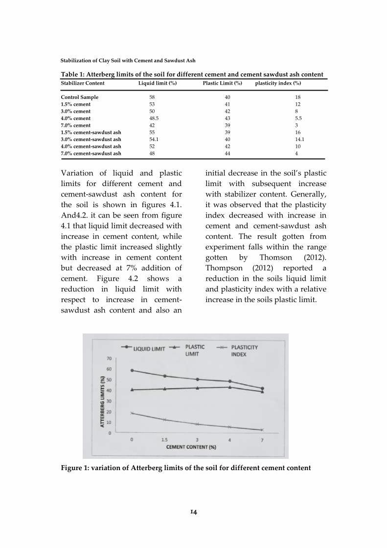
Table 1: Atterberg limits of the soil for different cement and cement sawdust ash content Stabilizer Content Liquid limit (%) Plastic Limit (%) plasticity index (%)
Control Sample 58 40 18
1.5% cement 53 41 12
3.0% cement 50 42 8
4.0% cement 48.5 43 5.5
7.0% cement 42 39 3
1.5% cement-sawdust ash 55 39 16
3.0% cement-sawdust ash 54.1 40 14.1
4.0% cement-sawdust ash 52 42 10
7.0% cement-sawdust ash 48 44 4
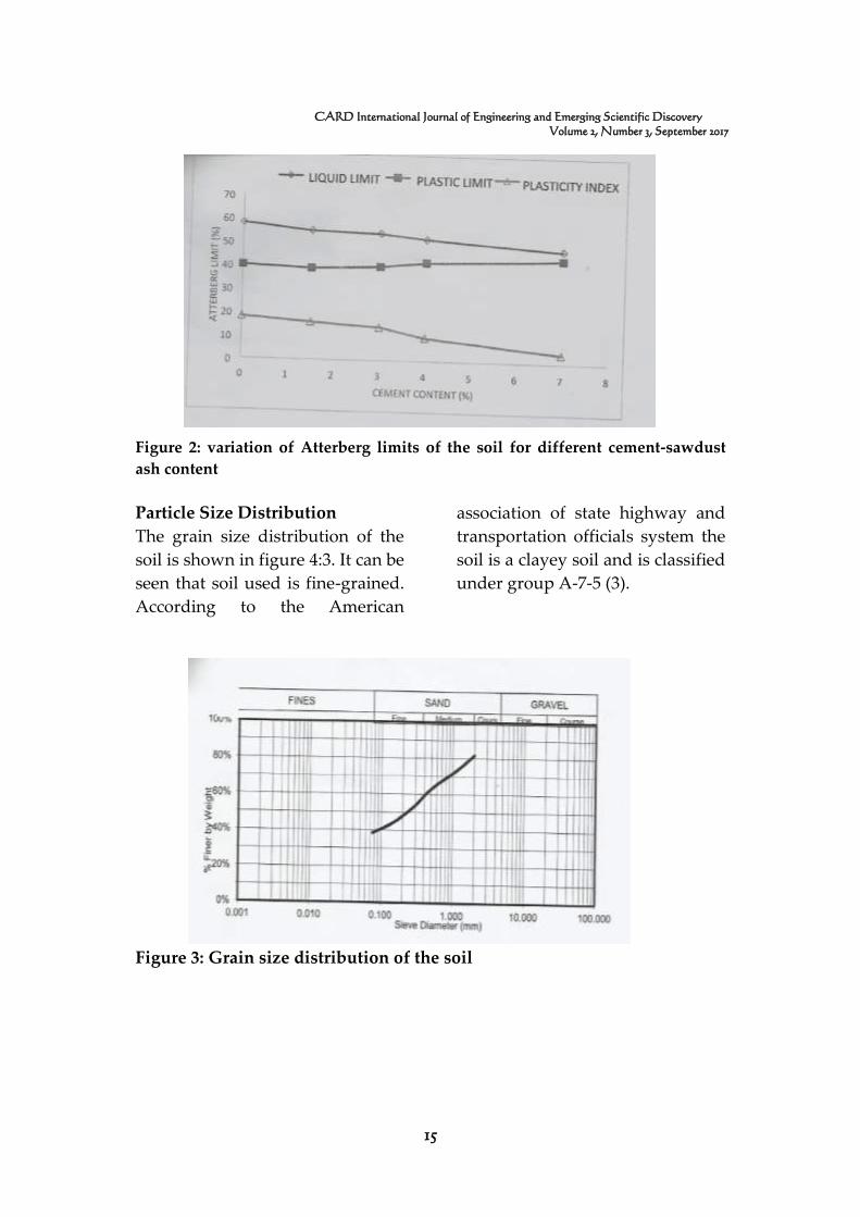
Variation of liquid and plastic
limits for different cement and
cement-sawdust ash content for
the soil is shown in figures 4.1.
And4.2. it can be seen from figure
4.1 that liquid limit decreased with
increase in cement content, while
the plastic limit increased slightly
with increase in cement content
but decreased at 7% addition of
cement. Figure 4.2 shows a
reduction in liquid limit with
respect to increase in cement-
sawdust ash content and also an
initial decrease in the soil’s plastic
limit with subsequent increase
with stabilizer content. Generally,
it was observed that the plasticity
index decreased with increase in
cement and cement-sawdust ash
content. The result gotten from
experiment falls within the range
gotten by Thomson (2012).
Thompson (2012) reported a
reduction in the soils liquid limit
and plasticity index with a relative
increase in the soils plastic limit.
Figure 1: variation of Atterberg limits of the soil for different cement content
15
CARD International Journal of Engineering and Emerging Scientific Discovery
Volume 2, Number 3, September 2017
Figure 2: variation of Atterberg limits of the soil for different cement-sawdust
ash content
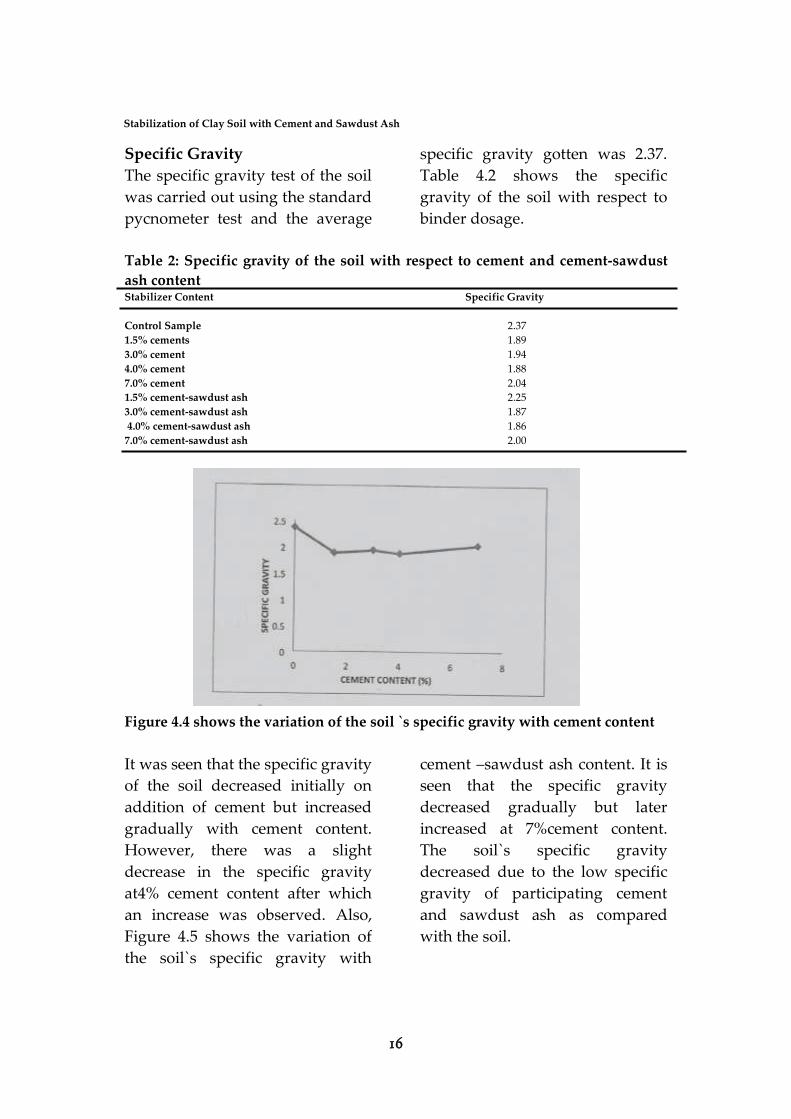
Particle Size Distribution
The grain size distribution of the
soil is shown in figure 4:3. It can be
seen that soil used is fine-grained.
According to the American
association of state highway and
transportation officials system the
soil is a clayey soil and is classified
under group A-7-5 (3).
Figure 3: Grain size distribution of the soil
16
Stabilization of Clay Soil with Cement and Sawdust Ash
Specific Gravity
The specific gravity test of the soil
was carried out using the standard
pycnometer test and the average
specific gravity gotten was 2.37.
Table 4.2 shows the specific
gravity of the soil with respect to
binder dosage.
Table 2: Specific gravity of the soil with respect to cement and cement-sawdust
ash content Stabilizer Content Specific Gravity
Control Sample 2.37
1.5% cements 1.89
3.0% cement 1.94
4.0% cement 1.88
7.0% cement 2.04
1.5% cement-sawdust ash 2.25
3.0% cement-sawdust ash 1.87
4.0% cement-sawdust ash 1.86
7.0% cement-sawdust ash 2.00
Figure 4.4 shows the variation of the soil `s specific gravity with cement content
It was seen that the specific gravity
of the soil decreased initially on
addition of cement but increased
gradually with cement content.
However, there was a slight
decrease in the specific gravity
at4% cement content after which
an increase was observed. Also,
Figure 4.5 shows the variation of
the soil`s specific gravity with
cement –sawdust ash content. It is
seen that the specific gravity
decreased gradually but later
increased at 7%cement content.
The soil`s specific gravity
decreased due to the low specific
gravity of participating cement
and sawdust ash as compared
with the soil.
17
CARD International Journal of Engineering and Emerging Scientific Discovery
Volume 2, Number 3, September 2017
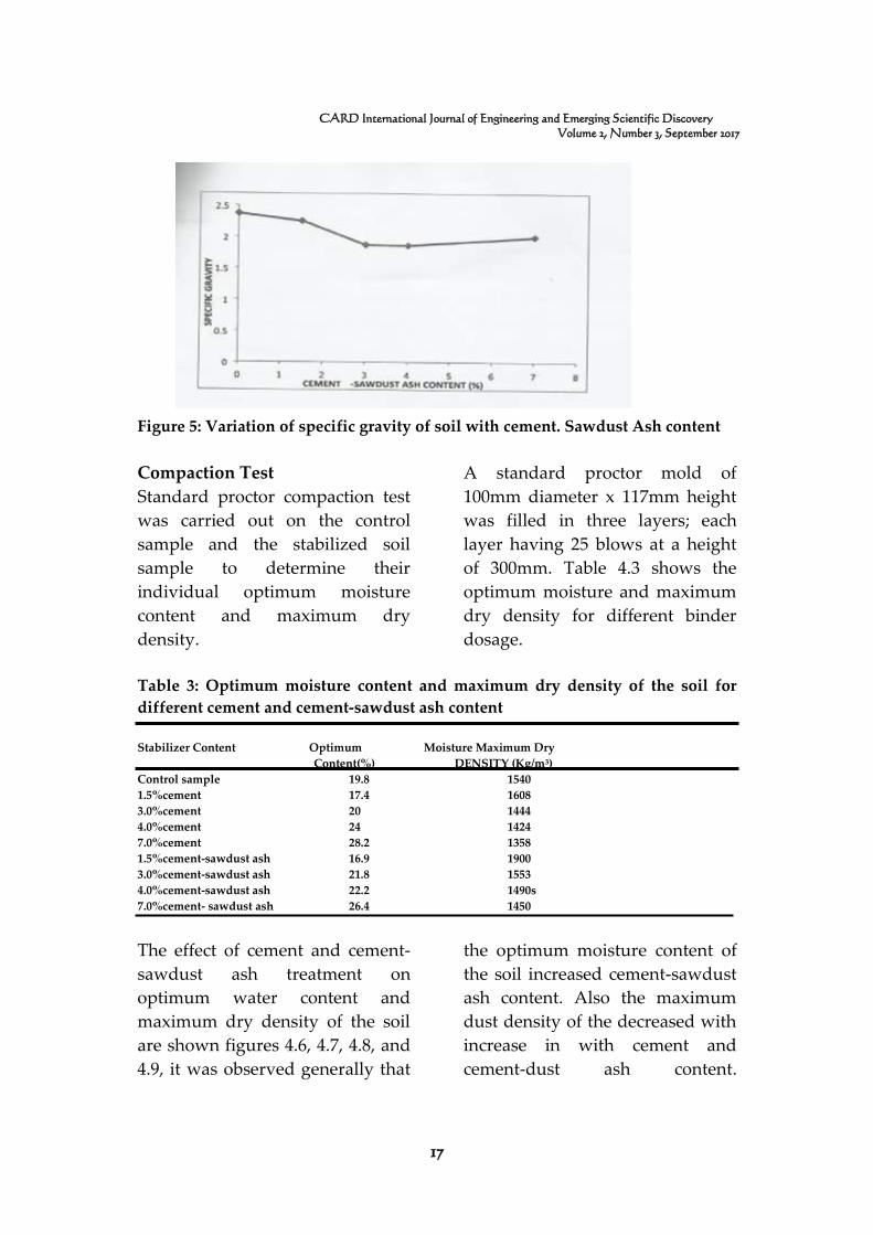
Figure 5: Variation of specific gravity of soil with cement. Sawdust Ash content
Compaction Test
Standard proctor compaction test
was carried out on the control
sample and the stabilized soil
sample to determine their
individual optimum moisture
content and maximum dry
density.
A standard proctor mold of
100mm diameter x 117mm height
was filled in three layers; each
layer having 25 blows at a height
of 300mm. Table 4.3 shows the
optimum moisture and maximum
dry density for different binder
dosage.
Table 3: Optimum moisture content and maximum dry density of the soil for
different cement and cement-sawdust ash content
Stabilizer Content Optimum Moisture Maximum Dry
Content(%) DENSITY (Kg/m3)
Control sample 19.8 1540
1.5%cement 17.4 1608
3.0%cement 20 1444
4.0%cement 24 1424
7.0%cement 28.2 1358
1.5%cement-sawdust ash 16.9 1900
3.0%cement-sawdust ash 21.8 1553
4.0%cement-sawdust ash 22.2 1490s
7.0%cement- sawdust ash 26.4 1450
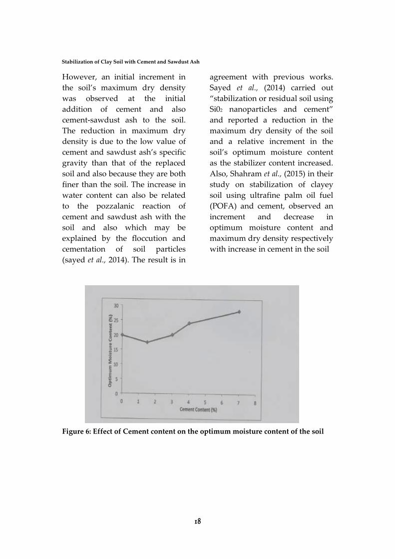
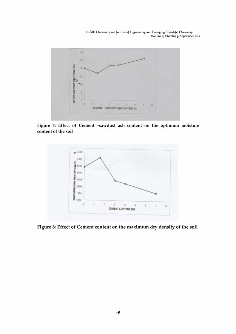
The effect of cement and cement-
sawdust ash treatment on
optimum water content and
maximum dry density of the soil
are shown figures 4.6, 4.7, 4.8, and
4.9, it was observed generally that
the optimum moisture content of
the soil increased cement-sawdust
ash content. Also the maximum
dust density of the decreased with
increase in with cement and
cement-dust ash content.
18
Stabilization of Clay Soil with Cement and Sawdust Ash
However, an initial increment in
the soil’s maximum dry density
was observed at the initial
addition of cement and also
cement-sawdust ash to the soil.
The reduction in maximum dry
density is due to the low value of
cement and sawdust ash’s specific
gravity than that of the replaced
soil and also because they are both
finer than the soil. The increase in
water content can also be related
to the pozzalanic reaction of
cement and sawdust ash with the
soil and also which may be
explained by the floccution and
cementation of soil particles
(sayed et al., 2014). The result is in
agreement with previous works.
Sayed et al., (2014) carried out
“stabilization or residual soil using
Si02 nanoparticles and cement”
and reported a reduction in the
maximum dry density of the soil
and a relative increment in the
soil’s optimum moisture content
as the stabilizer content increased.
Also, Shahram et al., (2015) in their
study on stabilization of clayey
soil using ultrafine palm oil fuel
(POFA) and cement, observed an
increment and decrease in
optimum moisture content and
maximum dry density respectively
with increase in cement in the soil
Figure 6: Effect of Cement content on the optimum moisture content of the soil
19
CARD International Journal of Engineering and Emerging Scientific Discovery
Volume 2, Number 3, September 2017
Figure 7: Effect of Cement –sawdust ash content on the optimum moisture
content of the soil
Figure 8: Effect of Cement content on the maximum dry density of the soil
20
Stabilization of Clay Soil with Cement and Sawdust Ash
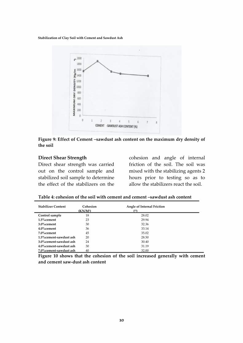
Figure 9: Effect of Cement –sawdust ash content on the maximum dry density of
the soil
Direct Shear Strength
Direct shear strength was carried
out on the control sample and
stabilized soil sample to determine
the effect of the stabilizers on the
cohesion and angle of internal
friction of the soil. The soil was
mixed with the stabilizing agents 2
hours prior to testing so as to
allow the stabilizers react the soil.
Table 4: cohesion of the soil with cement and cement –sawdust ash content
Stabilizer Content Cohesion Angle of Internal Friction
(KN/M2) (O)
Control sample 18 28.02
1.5%cement 23 29.94
3.0%cement 30 32.36
4.0%cement 36 33.14
7.0%cement 45 35.02
1.5%cement-sawdust ash 20 28.50
3.0%cement-sawdust ash 24 30.40
4.0%cement-sawdust ash 30 31.19
7.0%cement-sawdust ash 40 32.00
Figure 10 shows that the cohesion of the soil increased generally with cement
and cement saw-dust ash content
21
CARD International Journal of Engineering and Emerging Scientific Discovery
Volume 2, Number 3, September 2017
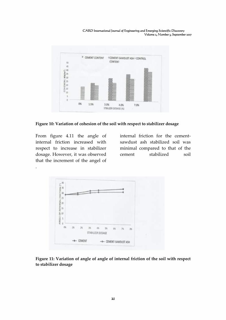
Figure 10: Variation of cohesion of the soil with respect to stabilizer dosage
From figure 4.11 the angle of
internal friction increased with
respect to increase in stabilizer
dosage. However, it was observed
that the increment of the angel of
internal friction for the cement-
sawdust ash stabilized soil was
minimal compared to that of the
cement stabilized soil
.
Figure 11: Variation of angle of angle of internal friction of the soil with respect
to stabilizer dosage
22
Stabilization of Clay Soil with Cement and Sawdust Ash
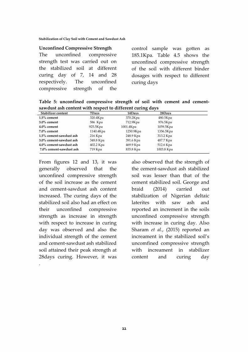
Unconfined Compressive Strength
The unconfined compressive
strength test was carried out on
the stabilized soil at different
curing day of 7, 14 and 28
respectively. The unconfined
compressive strength of the
control sample was gotten as
185.1Kpa. Table 4.5 shows the
unconfined compressive strength
of the soil with different binder
dosages with respect to different
curing days
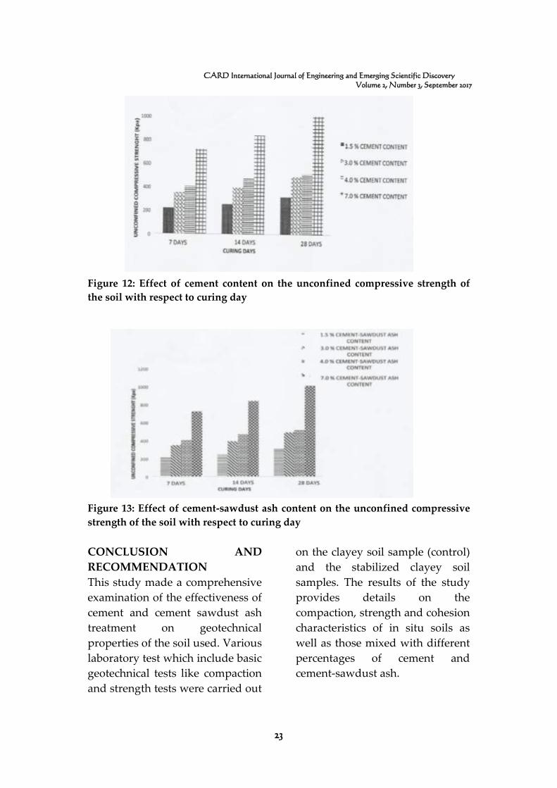
Table 5: unconfined compressive strength of soil with cement and cement-
sawdust ash content with respect to different curing days Stabilizer content 7Days 14Days 28Days
1.5% cement 320.4Kpa 370.2Kpa 480.5Kpa
3.0% cement 586 Kpa 712.9Kpa 976.5Kpa
4.0% cement 925.5Kpa 1001.4Kpa 1059.5Kpa
7.0% cement 1140.4Kpa 1250.9Kpa 1356.5Kpa
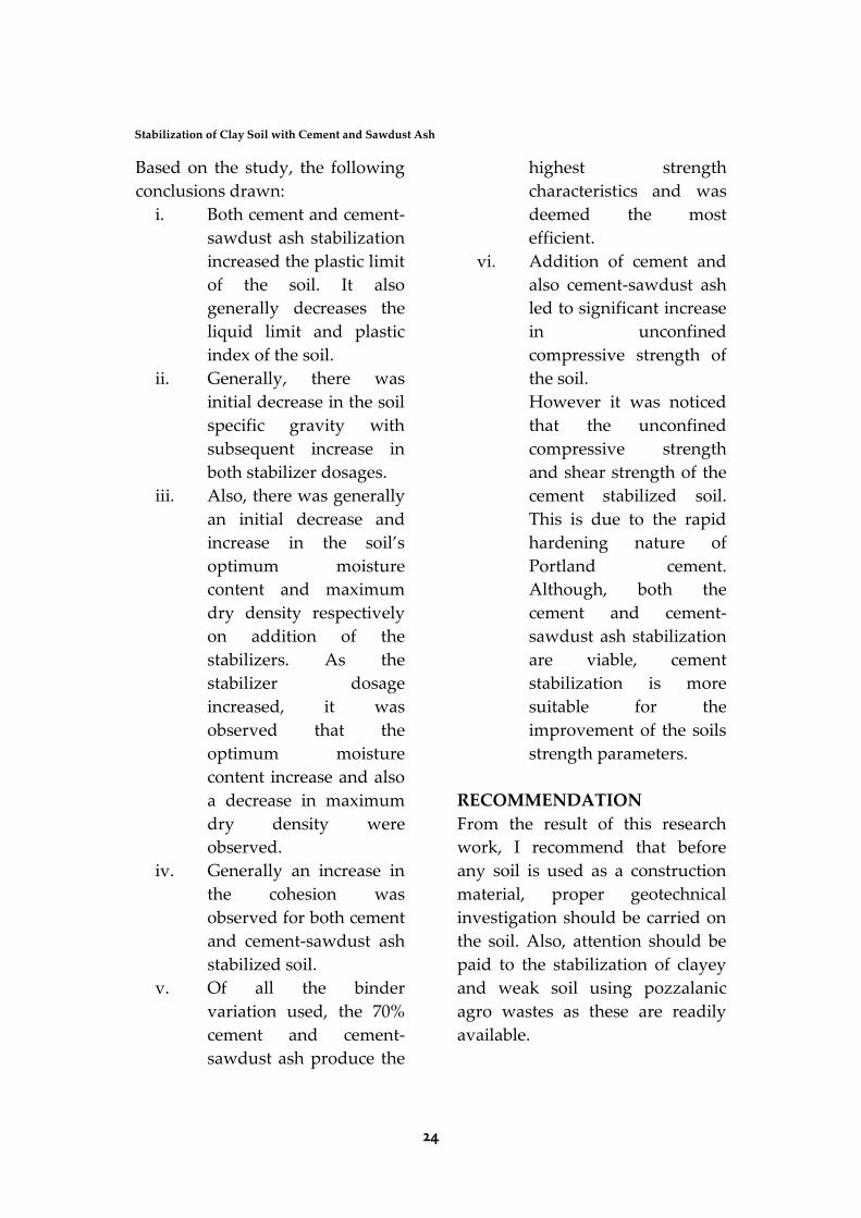
1.5% cement-sawdust ash 216 Kpa 248.9 Kpa 313.2 Kpa
3.0% cement-sawdust ash 348.8 Kpa 391.6 Kpa 487.7 Kpa
4.0% cement-sawdust ash 402.2 Kpa 469.9 Kpa 512.6 Kpa
7.0% cement-sawdust ash 719 Kpa 835.8 Kpa 1003.8 Kpa
From figures 12 and 13, it was
generally observed that the
unconfined compressive strength
of the soil increase as the cement
and cement-sawdust ash content
increased. The curing days of the
stabilized soil also had an effect on
their unconfined compressive
strength as increase in strength
with respect to increase in curing
day was observed and also the
individual strength of the cement
and cement-sawdust ash stabilized
soil attained their peak strength at
28days curing. However, it was
also observed that the strength of
the cement-sawdust ash stabilized
soil was lesser than that of the
cement stabilized soil. George and
braid (2014) carried out
stabilization of Nigerian deltaic
laterites with saw ash and
reported an increment in the soils
unconfined compressive strength
with increase in curing day. Also
Sharam et al., (2015) reported an
increament in the stabilized soil’s
uncomfined compressive strength
with increament in stabilizer
content and curing day
.
23
CARD International Journal of Engineering and Emerging Scientific Discovery
Volume 2, Number 3, September 2017
Figure 12: Effect of cement content on the unconfined compressive strength of
the soil with respect to curing day
Figure 13: Effect of cement-sawdust ash content on the unconfined compressive
strength of the soil with respect to curing day
CONCLUSION AND
RECOMMENDATION
This study made a comprehensive
examination of the effectiveness of
cement and cement sawdust ash
treatment on geotechnical
properties of the soil used. Various
laboratory test which include basic
geotechnical tests like compaction
and strength tests were carried out
on the clayey soil sample (control)
and the stabilized clayey soil
samples. The results of the study
provides details on the
compaction, strength and cohesion
characteristics of in situ soils as
well as those mixed with different
percentages of cement and
cement-sawdust ash.
24
Stabilization of Clay Soil with Cement and Sawdust Ash
Based on the study, the following
conclusions drawn:
i. Both cement and cement-
sawdust ash stabilization
increased the plastic limit
of the soil. It also
generally decreases the
liquid limit and plastic
index of the soil.
ii. Generally, there was
initial decrease in the soil
specific gravity with
subsequent increase in
both stabilizer dosages.
iii. Also, there was generally
an initial decrease and
increase in the soil’s
optimum moisture
content and maximum
dry density respectively
on addition of the
stabilizers. As the
stabilizer dosage
increased, it was
observed that the
optimum moisture
content increase and also
a decrease in maximum
dry density were
observed.
iv. Generally an increase in
the cohesion was
observed for both cement
and cement-sawdust ash
stabilized soil.
v. Of all the binder
variation used, the 70%
cement and cement-
sawdust ash produce the
highest strength
characteristics and was
deemed the most
efficient.
vi. Addition of cement and
also cement-sawdust ash
led to significant increase
in unconfined
compressive strength of
the soil.
However it was noticed
that the unconfined
compressive strength
and shear strength of the
cement stabilized soil.
This is due to the rapid
hardening nature of
Portland cement.
Although, both the
cement and cement-
sawdust ash stabilization
are viable, cement
stabilization is more
suitable for the
improvement of the soils
strength parameters.
RECOMMENDATION
From the result of this research
work, I recommend that before
any soil is used as a construction
material, proper geotechnical
investigation should be carried on
the soil. Also, attention should be
paid to the stabilization of clayey
and weak soil using pozzalanic
agro wastes as these are readily
available.
25
CARD International Journal of Engineering and Emerging Scientific Discovery
Volume 2, Number 3, September 2017
REFERENCES
Alam I., Naseer A., shah A.A.
(2015). Economical
stabilization of clay for
earth buildings construction
in Rainy and Flood Prone
Areas. Construction and
Building Materials 77,154-
159.
Amsterdam Errol Van (2010).
Construction materials for
civil engineering, Kenwyn,
Fourth impression press.
Basharad Isaac (1989).
University of California,
Retrieved from
www.clays.org/journal/arch
ive/volume%206/6-1-
110.pdf
Deepiya R., durga N., Steffi j.,
Ayyappan S.(2014).
Stabilization of clay soil
using Quary Dust and lime.
International Journal of
Advanced Information
science and technology
32(32), 111-114.
George Rowland Otoko & Braide
K. Hones (2014).
Stabilization of Nigerian
deltaic laterites with saw
dust ash. International
journal of scientific research
and management 2(8), 1287-
1292.
Goodarzi A.R. and salami M.
(2015). Stabilization
treatment of a dispersive
clayey soil using granulated
blast furnace slag and basic
oxygen furnace slag.
Applied Clay Science 108,
61-69.
Galan-Marin C., Rivera-Gomez C.,
Petric J. (2010). Clay-based
composite stabilized with
natural polymer and fibre.
Constructiob and Building
Materials 24, 1462-1468.
Ishibashi isao and Hazarika
Haezmental (2011).soil
mechanics fundamentals,
New York, institute of
Technology
(2016).Reterieved June 23,
2016 from http/www.
Iitgn.ac.in/research/stl/direc
tshear.php
Jonathan (2016). Specific Gravity
of soil. Retrieved june 23,
2016 from https:/stemsoup.
Wordpress.com/2011/02/22/
specifc-gravity-of soil
Kheemissa Mohamed and
Mahamedi Adelkrim (2014).
Cement and lime mixture
stabilization of an
expansive overconsolidated
clay. Science 95, 104-110.
26
Stabilization of Clay Soil with Cement and Sawdust Ash
Khemissa Mohamedi and
Mohamedi Abdelkerim
(2015).stabilization of an
expensive overconsolidated
clay using hydraulic
binders. Housing and
Building National Research
center journals 11, 82-92.
Lea, F.M. (1970).The chemistry of
cement and
concrete,Edward Arnold
(publishers) Ltd, London.
Masaki kikizume and Masaaki
Terashi (2013).The deep
mixing method,New York.
Taylor’printing press.
Modarres Amir and Nosoudy
Yaser Mohammedi
(2016).clay stabilization
using coal waste and
lime_Teachnical impacts.
Applied clay science soil
116-117,281-288.
Naorzlan Khalid, Mazidah
Mukri,Faizah Kamarudin,
Mohd Fadil Arashad
(2012).clay soil stabilized
Using Waste paper sludge
Ash (WPSA) Mixtures.
Electronic Journers of
Geotechnical Engineering
17, 1215-1225.
O’flaherty C.A (2002).Highways
(fourth Edition), Arizona,
University of Arizona press.
Pramod S. patil, J.R. Mail, Ganesh
V.Tapkire, H.R. kumavat
(2014).Innovatite
teahniques of waste plastic
used in concrete mixture.
international journals of
Research in Engineering
and Technology, 3(9), 29-
32,2014.
Raheem A.A, Olasunkanmi
B.S.,Folorunso c.s
(2012).saw Dust Ash as
partial Replacement for
Cement in Concrate.
Organization, Technology
And Management In
Construstion (An
International
journal)4(2),474-480
Raj purrushothama (1999). Ground
improvement techniques.
Arizona, Arizona printing
press.
Randy R.Rapp and Bradly
L.Benhart
(Eds).(2014),pature
University press.
Raoul Jauberthie, franck Rendell,
Damien Rangeard, Laurent
Molez (2010).stabilization of
Esttuarine sitl with Lime
27
CARD International Journal of Engineering and Emerging Scientific Discovery
Volume 2, Number 3, September 2017
And/Or Cement.Applied
clay scinence 50,395-400.
Ritter, Michael E. The physical
Environment: an
Introduction to physical
Geography (2006). Retrieve
d June 23, from
http:/www.earthonlinemed
al.com/ebooks/tpe-3e/title-
page.html
Sayed Hessam Bahmani,Bujang
B.K. Huat, Afshin Asadi,
Nima Farzadnia (2014).
Stabilization of residual soil
using si02 nanoparticles
and cement. Construction
and Building Materials
64,350-359.
Schlumberger Limited
(2016).Unconfied
compressive strength.
Retrieved June 23, 2016
http:/www.glossary.oilfied.
slb.com/Terms/u/unconfine
d-compressive-strength.
aspx.
Shahram pourakber,Afshin Asadi,
Bujang B.K. Huat,
Mohammad Hamed
fasihnikoutalab
(2015).stabilization of
clayey soil using ultrafine
palm oil fuel ash
(POFA)and cement
.Transportation Geotechnics
3,24-35.
Shish pal, vinod kumer sonthwal,
jasvir S Rattan (2015).
Review on Stabilization of
Using polypropylene as
waste fibre Material.
International Journal of
Innovative Research in
science, Engineering and
Techology, 4(11), 10453-
10458.
Seco A,Ramirez F., Miqueleiz L.
and Garcia B. (@010).
Stabilization of expensive
soils for use in construction.
Applied clay science
51,348-352.
The Columbia electronic
encyclopedia 6th ed. ,2012
retrieved from
www.infoplease.com/encyl
opedia/science/clay.html
2015.
Tyagher S.T.,Utsev J.T., Adagba T.
(2011).stability of saw Dust
Ash-Lime Mixture for
production of sandcrete
Hollow Blocks. Nigerian
Journal of Tachnology
30(1), 79-84.