Embed Size (px)
Citation preview

STAFFORDSHIRE COUNTY COUNCIL
Place
SKID RESISTANCE
POLICY
Helen Riley Deputy Chief Executive and Director of Place 1 Staffordshire Place Stafford ST16 2LP August 2013

i
Contents
Chapter Page No.
Policy Overview 1
1 Introduction 2
2. Legislation 4
3. Skid Resistance 5
4. Site Categories 6
5. Prioritisation Matrix 7
6. Desktop Site Investigation 9
7. On-Site Investigations 11
8. Warning Signs 12
9. Referral Process and Accident Clusters 13
10. Other Considerations 14
11. References 15

ii
Annexes Page No.
1. Measurement and Interpretation of Skid Resistance 17
2. SCRIM Survey Operational Procedures 21
3. Processing and Computation of SCRIM 24
4. Design Manual for Roads and Bridges 27
5. Improving Skid Resistance in Staffordshire 31
6. Fatal Accident Procedure 35
7. Footways, Cycleways, Paved Surfaces and 36 Other Vulnerable Users
Appendices
1. Site Category Review 41
2. On Site Investigation 42 3. Signage Location Investigation 43 4. Signage Removal 43
5. British Horse Society Website Form 44

1
Skid Resistance Policy
To consider and analyse the current skid resistance of the entire A, B and selected C/U class
network through the utilisation of SCRIM (Sideways Co-Efficient Routine Investigatory Machine)
and Griptester Mk2 information, and when combined with other relevant attributes, identify
sections of road that are a current cause for concern in relation to Staffordshire’s objective of
reducing accidents directly attributed to skidding.

2
1. Skid Resistance Strategy 1.1 Introduction
The purpose of Staffordshire's Skid Resistance Strategy is to describe how the management of
appropriate levels of skid resistance will be undertaken on Staffordshire’s maintained highways
to fulfil Staffordshire Skid Resistance Policy
The development of Staffordshire's Skid Resistance Strategy will be a major contributory factor
in enabling Staffordshire County Council, as the Local Highway Authority (LHA) for the publicly
maintainable local highway network within Staffordshire, to apply a consistent, long term
approach to the management of skid resistance on the County's highway assets.
This Skid Resistance Strategy forms part of the Staffordshire County Council (SCC) Transport
Asset Management Plan 2011-16.
1.2 Outside Consideration
The requirements contained within this Strategy to provide and maintain an appropriate level of
skid resistance upon the local highway network within Staffordshire, reflect the
recommendations of:
• Road Liaison Group's 'Well-maintained Highways', a Code of Practice for Highway
Maintenance Management - (July 2005).
• County Surveyor’s Society Guidance Note - Skidding Resistance (May 2005).
This Skid Resistance Strategy has, in part, been derived from the Highways Agency Standard
HD 28/04 - Skid Resistance, which is contained within the Design Manual for Roads and
Bridges (DMRB) Volume 7: Section 3 and details the skid resistance requirements for UK
Motorways and Trunk Roads. Reference has also been made to Highways Agency Standard
HD 36/06 - Surfacing Materials for New and Maintenance Construction, which is contained
within DMRB Volume 7: Section 5. This Standard, in part, details the aggregate requirements at
the design, construction and maintenance stages of a carriageways life, to ensure that
satisfactory skidding resistance is provided for the whole life cycle of the carriageway.
1.3 Concerned Parties
A copy of the current Strategy, for use by Staffordshire Highways personnel, will be located on
H:\Highways\Operational Info\Policy Documents\Operational Policies.

3
Copies of this Strategy will also be provided to the following:-
• Chief Executives Office – (Legal Services Unit - Development Services)
• Finance Directorate - (Insurance Services)
o SCC’s Insurers
o SCC’s Solicitors
• Neighbouring Highway Authorities
• Staffordshire Police (Accident & Investigation Unit)
Access to this Strategy will also be available to members of the public via the Staffordshire
Web.
1.4 Terms and Guidance
In this Strategy, the term “skid resistance” refers to the frictional properties of the road surface,
measured using a specified device, under standardised conditions. The term always refers to
measurements made on wet roads, unless specifically stated otherwise.
This Strategy provides advice and guidance to assist the engineer in determining an appropriate
level of skid resistance for each location. It lays down the procedure to be used for measuring
the skid resistance and, for cases where the measured skid resistance is below a
predetermined level, known as the Investigatory Level; it provides a methodology to assist the
engineer in assessing the requirement for remedial works. Remedial works will be subject to an
economic assessment of the costs and benefits before proceeding, to promote the best use of
maintenance budgets.
1.5 Updating the Strategy
Staffordshire's Skid Resistance Strategy will be reviewed and updated as necessary, every 3
years. Should important guidance be issued mid-term, this will be added to the strategy as an
interim addendum until a formal review is due and the interim addendum released / re-issued as
outlined above.

4
2. Legislation
2.1 Legal Requirement
Staffordshire County Council, as the Local Highway Authority (LHA) for Staffordshire, has a
statutory duty under Section 41 of the Highways Act 1980, to maintain those highways.
Section 58 of the 1980 Highways Act provides the LHA with a defence to counter a legal action
for negligence if one arose. The LHA must be able to prove, in a court of law, that it had taken
"such care as in all the circumstances was reasonably required to secure that the part of the
highway to which the action relates was not dangerous for traffic" based upon:
• The character of the highway and the traffic which was reasonably to be expected to use
it;
• The standard of maintenance appropriate for a highway of that character and used by
such traffic;
• The state of repair in which a reasonable person would have expected to find the
highway;
• Whether the Highway Authority knew, or could reasonably have been expected to know,
that the condition of the part of the highway to which the action relates was likely to
cause danger to users of the highway (e.g. evidence of previous complaint);
• Where the Highway Authority could not reasonably have been expected to repair that
part of the highway before the cause of the action arose, what warning notices of its
condition had been displayed.
Where a Section 58 defence is used by a LHA to counter a legal action for negligence, it should
be noted that the above are not the only criteria that a Court will consider and that decisions will
be based upon case precedent.
The 1980 Highways Act does not stipulate the standard of maintenance which should be
applied to highways and, indeed, it is accepted by the Courts that different standards will apply
to major roads and minor roads and footpaths that will be related to vehicle and pedestrian
usage and vehicle speeds. Thus a Court may recognise that it would not be practical for a LHA
to monitor and maintain adequate levels of skidding resistance on all parts of the highway for
which they are responsible, since to attempt to do so, would not be considered to be
“reasonably practicable”.

5
2.2 Skid Resistance Development
As a responsible LHA, Staffordshire County Council has developed a Skid Resistance Strategy.
This has been produced to ensure that the County Council is able to show that it has
implemented suitable highways management procedures, with regard to the maintenance of
adequate levels of skid resistance across the network, taking account of a variety of factors.
This will allow the County Council to produce a robust defence, which can be used in a court of
law, if a road traffic accident occurs where it is alleged that deficient skidding resistance of a
particular section of the highway network may have been contributory to the cause of the
accident.
3. Skid Resistance
3.1 Staffordshire’s Skid Resistance
Various types of equipment are available for measuring skid resistance. Staffordshire adopts
the use the SCRIM and Griptester MK2.
Within Staffordshire, the A/B class network is surveyed annually in one direction, except dual
carriageways, which are surveyed in both directions. Up to 10% of the C class network, and ad-
hoc C/U class requests, are also collated annually.
More information related to the SCRIM surveying process is available in Annex 1-3.
3.2 Surveying Process
The surveying strategy is planned so that the effects of seasonal variation, both within a single
season and/or between successive years, can be taken into account in the determination of the
Characteristic SCRIM Coefficient (CSC) for any particular length of road.
Staffordshire calculates the CSC of each section of the highway by using the Single Annual
Survey Method (See Appendix 3 A3.12). This method estimates the underlying skid resistance
once the effect of any seasonal variation has been taken into account. This value will be taken
to represent the state of polish of the road surface.
Once received the data is processed typically this will include:
• Application of correction factor, e.g. to correct the raw reading depending on the time of
year the survey was undertaken;
• Multiplication by the Index of SFC applicable to the SCRIM at the time it was making the
measurement;
• Calculation of the CSC;
On receipt of processed survey data, the Schemes Delivery Section shall check that the whole
of the specified network has been surveyed. For sections of highway where accurate measures
were not possible the most recent survey data will be used.

6
4. Site Categories
4.1 Assignment
The objective of setting an Investigatory Level (IL) for a site is to assess the nature of the site
and assign an appropriate level of skid resistance. The Site Categories and associated
Investigatory Levels that have been assigned to the highway network within Staffordshire are
defined in Table 4.1. This table has been derived from HD 28/04, however, it been altered to
reflect the lower traffic levels and more diverse nature of the highways for which Staffordshire
County Council are responsible.
The Site Category most appropriate to the layout of the site will be selected from the list in
Table 4.1. If more than one Site Category applies then the highest IL is assigned, if two equal
ILs apply to a location then priority is given to road layout over road geometry.
Investigatory Levels are applied to 100m averaging lengths, with the exception of Site
Categories Q and K which will normally be the 50m approach to the feature and Site Category
R which are based on 10m averaging lengths. Residual lengths less than 50% of a complete
averaging length may be appended to the penultimate length, providing the Site Category is the
same.
Table 4.1 – Setting Site Categories along a Network

7
4.2 Re-Assessment
A review of the Investigatory Level of a site shall be carried out when a substantial change to
the network is made, that would require a revised Investigatory Level and/or Site Category (see
Appendix 1; SRF1).
5. Prioritisation Matrix
5.1 A and B Class Roads
To prioritise between all SCRIM deficient locations over the A and B class surveyed network,
Staffordshire County Council uses a weighted ruleset table 5.1. This scoring matrix takes into
account:
• The most recent SCRIM reading
• The current 3 years Killed and Seriously Injured (KSI) figures (In Wet / Damp conditions)
• The Maximum Speed at the SCRIM deficient location
• The Site Category of the SCRIM deficient location
• The current 3 years Slight Accident figures (In Wet / Damp conditions)
These attributes have been selected as those which will have a major influence on the identified
SCRIM deficient locations and thereby enable the engineer to prioritise for investigation
Table 5.1 – A-B Road Priority Scoring Matrix
Criterion Weight
B C , D Q K R G1 G2 S1 S2 S3
0.63 0.75 3.50 4.00 3.13 1.63 2.00 2.00 2.50 3.00
210
Site
Category
Slight Wet
Accidents
KSI Wet
Accidents
0 1
10
0 1
32
2
13%
Amount
Below IL
Speed
Limit
3 4
>=4
>=43
3
60 70
2
50
Scoring
A/B Road Priority Scoring
20%
7%
27%
Scored on an X2 relationship with a max score of 4
Range from 0 - (-.2)33%
4.003.202.401.600.80
<=30 40
4

8
Scrim
Weighted the highest amongst the scoring criteria, the SCRIM deficiency has been assessed by
machine and relates directly to the section of road in question. It is fair, therefore, to assume it
is a major contributing factor to the potential for accidents at this site.
Wet - KSI’s (3 Year)
The next criterion focuses on the authorities’ corporate aim of reducing accidents on the
network. Weighting this as such thereby highlights those sections of road that have had KSI’s
in the locality of the deficient location. Whilst the KSI’s might not be directly attributed to the
SCRIM deficiency at that location the likelihood that it played a part should be considered.
Speed
Speed is the third weighted criterion, as speed increases the potential risks and severity of
incident increases for all road users.
Site Category
Site category of the SCRIM deficient location was then chosen as the forth differentiating factor
as the demand on the user varies, dependent upon the geometry and layout of the network at
that location.
Wet - Slight Accidents (3 years)
The final consideration is slight accidents although still an important criterion for prioritisation
purposes, the volume of slight accidents across the county in a 3 year period means it is not
logical to rate these higher than the criteria listed previously.
Scoring
Each category has been given an obtainable score of 4 and weighted 1-5 in the order above,
this produces a maximum obtainable score of 60 per deficient location.
5.2 C and U Class Roads
Due to the vast differences between all C and U roads on the Staffordshire network, table 5.1
above, cannot be applied in the same manor for prioritisation of deficient locations on these
classes. To account for the varying levels of usage and therefore, the varying amount of users
being subjected to the deficient location, Staffordshire have incorporated Traffic Flows as an
extra criterion to separate between roads that are surveyed. The scoring matrix for C and U
class roads is detailed in table 5.2.

9
Table 5.2 – C Road Priority Scoring Matrix
Criterion Weight
B C , D Q K R G1 G2 S1 S2 S3
0.63 0.75 3.50 4.00 3.13 1.63 2.00 2.00 2.50 3.00
Traffic
Flows
>=4321
<=30 40 50 60 70
>75015001-75002001-50001001-2000<1001
0
4
0 1 2 3 >=4
0.8
0 1 2 3
4
43.22.41.6
3.22.41.60.8
0 1 2 3
Scoring
C/U Road Priority Scoring
5%
10%
14%
19%
24%
29%Range from 0 - (-.2)
Scored on an X2 relationship with a max score of 4
Slight Wet
Accidents
Site
Category
Speed
Limit
KSI Wet
Accidents
Amount
Below IL
4
6. Desktop Site Investigation
Upon receipt of the annual A and B road network SCRIM data and targeted C/U road network
grip test results, the engineer will process the information against tables 5.1 and 5.2
respectively. This enables the scoring and prioritisation of deficient locations for treatment
recommendations and warning signage. Further investigation into these prioritised locations is
carried out in two phases, initially a desktop study with subsequent on site investigation if
required.
6.1 Desktop Procedure for A and B Class Roads
Staffordshire will endeavour to complete the investigation of up to the top 100 scoring deficient
locations within a 3 month timeframe upon receipt of the SCRIM data. The method for the
desktop procedure is detailed in figure 6.1
The deficient locations to be investigated will be compared against the following year’s
preventative and structural maintenance programmes. This will determine if the extents of the
deficient location will be treated within the next financial year. The possible outcomes are
detailed below:
• Those locations where full extents of deficiency fall within next years programmed works
and don’t meet the criteria of the signage policy as stated in 8.2 will require no further
action and will be signed off by a senior engineer. Figure 6.1 Outcome 2
• Those locations where full extents of deficiency fall within next years programmed works
that meet the criteria for signage will only have a signage location investigation (See
Appendix 3; SRF3), carried out within the 3 months of receipt of the processed
information. Figure 6.1 Outcome 1.

10
• Deficient locations that appear on the next financial years programmed works list whose
full extents are not currently covered by the proposed works shall be reviewed by the
senior engineer to determine whether they can be incorporated. If this is the case then
the above bullet point will be applied
• Where the extents are unable to be incorporated, the remaining locations in the top 100
will warrant a site investigation (See Appendix 2; SRF2) in accordance with figure 6.1
Outcome 4. Locations that at any point match the signage policy 8.2, will also have a
sign location investigation (See Appendix 3; SRF3) conducted at the same time. Figure
6.1 Outcome 3.
Figure 6.1 – Method of Investigating Top 100 Points

11
6.2 Desktop Procedure for C/U Class Roads
The analysis of the prioritised C/U class deficient locations will follow the same format as stated
in chapter 6. After scoring against table 5.2, up to the top 20 locations will follow the same
procedure as listed in paragraph 6.1. Staffordshire County Council has specifically set aside a
maximum of 10% of the available budget for the improvement of grip on the C/U class network.
Since testing of the whole C/U class network is not done annually, those deficient locations that
did not get prioritised in their surveyed year, will be re-scored in the following years skid
resistance analysis of the C/U class network.
Any ad hoc testing completed on the network as a result of injury investigation or other such
query will be individually accessed against figure 6.1. The ad hoc survey results will not be
compared for prioritisation of investigation against the routinely surveyed roads, as there is
special cause for concern at this location.
6.3 Transferring from Desktop to On-Site
Once the locations for site visits have been identified, a 55 metre buffer is then applied to each
deficient location. Any other deficient locations that fall within that buffer will be investigated
under the same assessment.
7. On-Site Investigations
7.1 Investigation Process
Following consideration as detailed in Chapter 6, On-site investigations by the engineer will
normally be completed within a 3 month timeframe on both the selected A/B Class and the C/U
Class deficient locations, utilising form SRF2 (see Appendix 2)
The results of the investigation, including whether further action is required, shall be
documented using SRF2 and retained electronically together with the identity of the assessor.
7.2 Investigation Findings
Following a site investigation the likely recommendations will normally be a surface treatment to
improve the skid resistance to an acceptable level. However, if the on-site investigation
identifies any characteristic of the site or road users’ behaviour that suggests other road safety
engineering measures could be appropriate, then these will be considered separately.
7.3 Prioritisation of Findings
The Senior Engineer will review and sign off all information gathered, and assess the
recommendations provided. Annex 4 and 5 provide more in-depth knowledge for the Senior
Engineer when assessing the recommendations. Where structural or preventative maintenance
has been recommended then this will be prioritised in accordance with the authority’s asset
value management process.

12
8. Warning Signs
8.1 Signs Used
The "Slippery Road" warning sign (Diagram 557 with Supplementary Plate to Diagram. 570) is
to be used in accordance with the instructions contained in The Traffic Signs Regulations and
General Directions 2002 and amendments thereof.
8.2 Signage Requirement
Following the prioritisation of the deficient locations, a sign location investigation (see Appendix
3; SRF3) may be carried out and warning signs will be erected at those locations that have a
speed limit greater than 30mph and with at least 1 KSI and/or 2 Slight accidents in the previous
3 years, regardless of when the location falls on the programme of works.
In all cases where warning signs are to be erected, a record shall be made, (see Appendix 3;
SRF3 and Appendix 4; SRF4) and retained electronically. This will enable mapping of the
current signs in use and allow for checks to be conducted on their validity.
Since warning signs are erected (if required) after a site investigation, it is particularly important
to complete site investigations within a reasonable time period supporting the selection of the
top 100 locations. This enables warning signs to be placed where they are needed without
undue delay.
8.3 Monitoring and Removal
This strategy provides a targeted use of signs and is designed to avoid a proliferation of signs
that would undermine their effectiveness and would not make best use of resources.
Warning signs shall be removed as soon as they are no longer required. This should be after
the surface treatment has been carried out. In all cases, the aim should be to avoid leaving
signs in place after their usefulness has expired to avoid “familiarity breeding contempt”.

13
9. Referral Process and Accident Clusters
9.1 Casualty reduction
Whilst the County Council use the policy above to reduce accidents across the network by
maintaining adequate levels of skid resistance, a separate casualty reduction team, focuses on
the task of analysing highway accident clusters and fatality cause.
9.2 Accident Cluster Sites
Accidents involving personal injury that are collected by Staffordshire Police are reported to the
County Council.
Searches of the database are carried out by the Council to identify cluster sites for detailed
investigation. Where common factors that can be treated are identified, remedial measures are
introduced to try to prevent similar accidents occurring.
Searches are carried out to identify sites where possible deficiencies in the road surface may be
contributing to the accidents recorded. Sites are identified where a significantly higher
percentage of accidents than would normally be expected have been recorded when the road
surface was wet. Sites are also identified where common factors are recorded such as skidding,
rear end collisions and loss of control.
All severities of accidents are considered during this process.
Sites identified are forwarded for detailed assessment and appropriate treatments are
introduced if deficiencies are confirmed. Where funding is limited, sites are prioritised for
treatment by carrying out a cost benefit analysis for each site.
Each fatal accident recorded is assessed in accordance with the County Council’s Fatal
Accident Procedure (Annex 6)
9.3 Reaction to Accident Cluster Sites
Upon receipt of such sites, if accurate current data is not available, the Griptester will be
utilised, thereby giving accurate measurements along the section of network, to help in
determining the causes of accidents. Since the site information has been referred from within
the County Council, the measurement will not be assessed against other sites on the network;
however in conjunction with the senior engineers’ recommendations regarding treatment and
timescales, the site will immediately be assessed for signage against paragraph 8.2, thereby
warning motorist in a timely manner.

14
10. Other Considerations
10.1 Footway and Horse Users
In Staffordshire, while pedestrians and horse users vulnerability is a concern. A risk analyses
and likelihood of event chart has shown that accidents relating to these user groups are low per
year, when compared to vehicular accidents. Staffordshire has developed a method for
gathering data, and proper procedure when treating network, where interaction with these users
is likely. These are located in Annex 7

15
11. References
Design Manual for Roads and Bridges
HD 28 (DMRB 7.3.1) Skid Resistance
HD 36 (DRMB 7.5.1) Surfacing Materials for New and Maintenance Construction
HD 36 (DRMB 7.5.2) Bituminous Surfacing Materials and Techniques
HD 39 (DRMB 7.2.5) Footway Design
HD 40 (DRMB 7.4.3) Footway Maintenance
Interim Advice Notes
49/13 – Use of Warning Signs for New Asphalt Surfaces
98/07 – Guidance for HA Service Providers on Implementing the Skid
Resistance Policy (HD 28/04)
157/11 - Thin Surface Course Systems – Installation and Maintenance
154/12 - Revision of SHW Clause 903, Clause 921 and Clause 942
155/12 - Revision of SHW notes for Guidance Sample Appendix 7/1
156/12 - Revision of Aggregate specification for Pavement Surfacing
Manual of Contract Documents for Highway Works
Volume 1 Specification
Volume 2 Notes for Guidance
Roads Liaison Group
Well Maintained Highways - Code of Practice for Highway Maintenance Management
Statutory Instruments
The Traffic Signs Regulations and General Directions 2002
County Surveyors Society
Guidance Note - Skidding Resistance - May 2005
CSS / British Horse Society – ‘Horses and Highway Surfacing’ -
A Guidance Note for Highway Authorities - (Ref No. - Eng/3-05)
‘The Assessment of Slip Resistance in Paved Areas for use by Pedestrians and Horse Riders’
(Ref No. – ENG/1-96)
British Standards Institute
BS EN 1097-8: 2000 Tests for the Mechanical and Physical Properties of Aggregates – Determination of the Polished Stone Value
BS EN 1338:2003 Concrete Paving Blocks - Requirements and Test Methods

16
BS EN 1338:2003 Concrete Paving Flags - Requirements and Test Methods
BS EN 1436:2007 Road Marking Materials - Road Marking Performance for Road Users
BS 7941-1:2006 Methods for Measuring the Skid Resistance of Pavement Surfaces. Sideway-force Coefficient Routine Investigation Machine
BS 7941-2:2000 Methods for Measuring the Skid Resistance of Pavement Surfaces. Test Method for Measurement of Surface Skid Resistance using the GripTester Braked Wheel Fixed Slip Device
BS EN 13036-4:2003 Road and Airfield Surface Characteristics. Test Methods. Method for Measurement of Slip / Skid Resistance of a Surface.
Other Reference Sources
Staffordshire County Council - 'Highway Safety Inspection Code of Practice'
Staffordshire County Council - ‘County Highways Network Management Policy’
Transport Research Laboratory Project Report PR/H/58/93 (SCRIM / GripTester Comparison)

17
ANNEX 1
BACKGROUND INFORMATION ON THE MEASUREMENT AND
INTERPRETATION OF SKID RESISTANCE
General
A1.1 When a vehicle travels over a road, each part of the tyre in contact with the road surface is
momentarily at rest. The frictional forces generated at these stationary contact areas between the
tyre and the road surface can allow vehicles to be manoeuvred. However, a vehicle will start to
skid whenever the available friction between the road surface and the tyre is insufficient to meet
the demands of the driver in whatever manoeuvre (including braking) they are attempting to
make.
A1.2 The friction available to a driver attempting a particular manoeuvre depends on many different
factors and is not constant during the manoeuvre. The influence of road surface characteristics is
described below. Other factors include the vehicle’s tyres and braking system, the dynamic
interaction of the vehicle suspension with the road geometry and environmental factors, such as
the temperature and the presence of water or other contaminants. The objective of
measurements carried out under the operation of this Strategy is to characterize the influence of
the road surface skid resistance and hence define the skid resistance available to road users.
Road Surface Properties
A1.3 The contribution of the road surface to the overall friction is known as skid resistance. In practice,
it is found that the skid resistance measured on dry, road surfaces is generally high, but that
lower and more variable measurements are obtained when the same road surfaces are wet or
damp. For this reason, measurements of skid resistance for the purpose of routine condition
monitoring are made on wetted road surfaces.
A1.4 The level of (wet road) skid resistance is dependent on two key properties of the surface, the
micro-texture and the texture depth (macro-texture). The fine scale micro-texture, on the surface
of aggregate particles and provided by the fines in the mixture, is the main contributor to wet
skidding resistance at low speeds and the main property measured in wet skid resistance tests.
Greater texture depth generates friction by physically deforming the tyre surface (hysteresis) and
also provides rapid drainage routes between the tyre and road surface.
A1.5 The effects of micro-texture and texture depth combine to influence the wet skidding resistance at
higher speeds. The standard SCRIM measurement is carried out at a slip speed less than
20km/h, much lower than the slip speed in locked-wheel braking from normal traffic speed. The
typical reduction of skid resistance from the 20km/h value at higher speeds, and the influence of
texture depth, is illustrated in Table A1.1. The effect of texture depth becomes apparent at
speeds as low as 50 km/h, but is increasingly significant at higher speeds.

18
Table A1.1 Typical Reduction in Skid Resistance
Compared with 20km/h Value
Effects of Traffic
A1.6 Under the action of traffic, the micro-texture becomes “polished”, leading to a reduction in skid
resistance. HD 36/06 (see Annex 5) requires the components of the surfacing mixture to satisfy
certain criteria in relation to their resistance to polishing, so that surfacing materials generally
provide adequate skid resistance during their service lifetimes.
A1.7 In combination with the specification of surfacing materials, the skid resistance of roads is
monitored to identify areas where the micro-texture has been lost as the surface has been
polished by traffic and treatment might, therefore, be needed to improve the skid resistance. This
is necessary because the performance in service cannot be predicted precisely from the
properties of the surfacing components and traffic levels, and the effects of manoeuvring vehicles
at the location might be greater than was anticipated at the time the surfacing was designed.
A1.8 Similarly, the texture depth of some types of road surfacing materials can reduce with time under
the combined influences of traffic flow, temperature and the nature of the surface. Texture depth
is also monitored and the measurement of texture depth is described in HD 29 (DMRB 7.3.2).
Early Life Skid Resistance of Asphalt Surfacings
A1.9 Different types of asphalt surfacing materials exhibit different skid resistance properties in the
initial period after laying, compared with the same surfacing materials that have been exposed to
traffic for a period of time. The method used within Staffordshire to remedy any reduction in early
life skid resistance of asphalt surfacing materials is described in Annex 5 of this Strategy.
Seasonal Variation of Skid Resistance
A1.10 After any initial period of wearing in, road surfaces reach an equilibrium state of polishing. For
roads where the traffic level is constant, the skid resistance will then fluctuate through seasonal
weathering and polishing cycles but will remain at about a constant level for many years. If traffic
levels subsequently increase or decrease, the position of the equilibrium will shift so that a lower
or higher overall level of skid resistance is observed, but with the same seasonal fluctuation
superimposed.
A1.11 An example of long-term variation in skid resistance is shown in HD 28/04: Appendix 1: Figure
A1.1.
A1.12 A suggested explanation for the annual variation is that in the winter (October to March) when the
roads are wet for much of the time, the detritus is mainly gritty so that the road surface becomes
Texture depth (mm SMTD) Speed
Below 0.5 0.5 - 0.8 Above 0.8
50 km/h 40% 30% 25%
120 km/h 70% 60% 50%

19
harsh and the skid resistance rises. The lowest skid resistance is generally observed in the
summer period, when the roads are wet for a relatively short time, the detritus on them is mainly
dusty so that the road surface becomes polished and the skid resistance falls. In practice, the
minimum skid resistance varies from year to year and occurs during different periods depending
on the prevailing weather conditions.
A1.13 Because the skid resistance varies continuously, various strategies have been developed to
provide a measurement that characterizes the state of polish of the micro-texture. Survey
strategy and processing procedures are designed to reduce the effect of the variation within a
year and/or between successive years, so the sites with low skid resistance can be identified
more accurately. Typically, measurements are made during the summer period, when the lowest
measured values are observed.
A1.14 The survey and analysis methods to be used for the purposes of this Strategy are described in
Annex 2 and Annex 3 of this Strategy.
Standardised Measurements
A1.15 To characterize the condition of the micro-texture, measurements of skid resistance are made
under standardised conditions that restrict the influence of other factors on the measurement as
far as possible. For example, measurements are made at a specified speed, using a specified
tyre and a controlled amount of water. Corrections may be applied to the measured value where
the specified standard conditions were not achieved, e.g. where it was not safe to maintain the
specified speed. Further details of test procedures are given in Annex 2.
A1.16 The measurements made and interpreted according to this Strategy; provide a guide to the
general condition of the road to assist in maintenance planning. Because they indicate the
general level of skid resistance under standardized conditions, the values do not relate directly to
specific accident situations, where other factors such as the tyre condition, vehicle speed and
type of manoeuvre attempted, all influence the level of friction generated at that time.
A1.17 In contrast, skid tests carried out by the Police for the purpose of reconstructing the situation
leading to an accident are intended to recreate the specific conditions of the accident. The results
of these different types of test cannot be compared precisely.
Relationship to Accident Risk
A1.18 Within normal ranges, low skid resistance does not cause accidents on its own although,
depending on the particular circumstances, it may be a significant contributory factor. The level of
skid resistance, even on a polished surface, will generally be adequate to achieve normal
acceleration, deceleration and cornering manoeuvres on sound surfaces that are wet but free
from other contamination. However, higher skid resistance can allow manoeuvres that demand
higher friction to be completed, e.g. to stop quickly or corner sharply. Higher skid resistance can
therefore reduce accidents in cases where drivers need to complete a more demanding
manoeuvre in order to avoid an accident. A key part of this Strategy is the judgment of locations
where this is more likely to occur, so that the provision of higher levels of skid resistance can be
targeted at these locations.
A1.19 Accident analyses have shown that there are relationships between measured skid resistance
and accident risk. These relationships are not precise, in that differences in skid resistance may

20
account for only a relatively small part of the difference in accident risk between individual sites
because of all the other factors involved. Nevertheless, they have allowed general observations
to be drawn that make it possible to provide guidance for managing the provision of skid
resistance on the network.
A1.20 The influence of skid resistance on accident risk is markedly different for roads with different
characteristics. For this reason, site categories have been defined to group roads with similar
characteristics.
A1.21 For some site categories, no statistically significant relationship, or only a weak relationship, is
observed between skid resistance and accident risk. A good example of this is motorways, where
the road design has minimized the potential for conflict between road users. Although the skid
resistance is still important, because of the need to provide uniform road characteristics, the level
of skid resistance can be lower than other categories.
A1.22 For other site categories, progressively more accidents are observed, on average, as the skid
resistance falls. For these categories, there are benefits in maintaining a higher level of skid
resistance to contribute to reducing the number of accidents at these sites.
A1.23 However, not all sites within a single category are equivalent in terms of their accident risk; there
is a range of accident risk present for individual sites within a single site category. This range is
not surprising when the range of characteristics present within a single nominal site category is
considered, e.g. in road design and traffic flow. It should also be noted that there is no boundary
at which the skid resistance passes from being “safe” to being “dangerous”.
A1.24 Judgment of the relative accident risk and appropriate level of skid resistance for different sites
within the same category forms a key part of the effective operation of this Strategy.

21
ANNEX 2
SCRIM SURVEY OPERATIONAL PROCEDURES
A2.1 This Annex lists the standard testing procedures that are required to limit the variability of skid
resistance measurements resulting from factors other than the road surface condition.
Testing Season
A2.2 For standardised tests, measurements shall be made during the testing season, defined as the
summer period 1 May – 30 September.
A2.3 In exceptional circumstances the testing season may be extended but only with the prior
agreement of Staffordshire County Council.
Testing Speed
A2.4 On all roads within Staffordshire, or where a SCRIM is being used without dynamic vertical load
measurement, the target test vehicle speed is 50km/h.
A2.5 The SCRIM driver shall maintain a vehicle speed as close to the target test speed as possible.
This is achievable for most parts of the network.
A2.6 If it is not safe or practical to maintain the target speed then, in exceptional circumstances, a
different speed may be used at the discretion of the SCRIM driver. The safety of the SCRIM and
other road users has priority at all times.
A2.7 The Investigatory Levels for the CSC values defined in Chapter 5 have been set in terms of the
50km/h standard testing speed. The method for applying speed corrections is given in Annex 3 of
this Strategy.
Testing Lane and Line
A2.8 All of the elements of the highway network to be tested within Staffordshire will be tested in one
direction each year. It can be assumed that, in general, the surfacing materials and traffic usage
and hence, the condition of the surface aggregate, will be consistent and therefore the results for
both lanes will be comparable. . For single lane dual carriageway's, testing will be carried out in
both directions and for two lane dual carriageways, lane one will be tested in both directions of
travel. This lane usually carries the heaviest traffic and can, therefore, be expected to show the
lowest skid resistance. In areas where this is not the case (for example, approaching points
where routes diverge and a greater proportion of heavy vehicles uses the offside lane) then a
different lane, or more than one lane will be tested.
A2.9 The test lane shall be as specified by Staffordshire County Council.
A2.10 SCRIM measurements shall be carried out with the test wheel in the nearside wheel path of the
running lane unless an alternative line has been agreed with Staffordshire CC.

22
A2.11 If it is necessary for the SCRIM to deviate from the test line (e.g. to avoid a physical obstruction
or surface contamination) the data shall be marked as invalid and eliminated from the standard
analysis procedure.
A2.12 On urban roads where roadside parking in unmarked positions is commonplace, there may be
two pairs of wheel paths – one followed at times of day when parked cars are mostly absent and
another when they are largely present. In such circumstances the line that normally carries the
most commercial vehicle traffic must be followed.
A2.13 In situations where the test line is prone to physical obstruction, for example by parked cars, then
an alternative test line must be agreed with Staffordshire CC to avoid recording invalid data for
the same length of road in successive years. Testing the offside wheel path might be an
appropriate alternative in these circumstances, with the aim of achieving a consistent test path,
year on year.
Testing on Bends
A2.14 There are no special requirements for testing on bends. At locations where a sharp bend is
combined with traffic braking or accelerating, the wheel path on the outside of the bend can
become more polished than the inside wheel path. This is taken into account in setting the
Investigatory Level (See Chapter 4).
Testing on Roundabouts
A2.15 Roundabouts can present practical problems regarding potential traffic conflicts and testing
speed. They range from small, mini-roundabouts to large grade-separated interchanges. Larger
roundabouts may have free-flowing traffic or traffic light controls at certain times of day.
A2.16 Mini-roundabouts or small island roundabouts should be treated as part of the main carriageway
test line and do not need to be tested separately. (This applies to the testing procedure – the
roundabout section may be assigned to a different Site Category to that of the main line.)
A2.17 On most roundabouts or interchanges, a line equivalent to the outermost lane should be tested.
A2.18 On roundabouts with lane markings for specific routes, a representative line should be chosen
broadly following the most polished path. Usually this will be that followed by most heavy
vehicles, which, because of their size, may not be able to keep to the marked lanes.
A2.19 The test line(s) to be followed at roundabouts shall be as agreed by the survey contractor and
Staffordshire CC. They will take into account the need for consistency in representative
measurements in successive surveys and possible variations in Site Category through the
intersection.
A2.20 On some smaller roundabouts where the distance between the arms is short, it may be
appropriate to record data at a shorter interval than the standard 10m length. Changes to the
recording interval will be specified by Staffordshire CC.

23
Ambient Conditions During Testing
A2.21 The ambient conditions can have an effect both on the skid resistance of the road and on the
measurements. The survey contractor shall record the weather conditions at the time of the
survey as required by BS7941-1:(2006).
A2.22 Testing in extremely strong side winds must be avoided because these can affect the
measurements by creating turbulence under the vehicle that causes the water jet to be diverted
from the correct line.
A2.23 Testing must be avoided in heavy rainfall or where there is standing water on the road surface.
Excess water on the surface can affect the drag forces at the tyre / road interface and influence
the measurements.
A2.24 Measurements shall not be undertaken when air temperatures are below 5°C.
A2.25 Staffordshire CC shall maintain a record of general conditions throughout the testing season.
Both the survey contractor and Staffordshire CC shall endeavour to record any road conditions
that could affect the results.
A2.26 Contamination of the road surface by mud, oil, grit, or other contaminants is to be noted and the
affected measurements identified so that results are eliminated from the standard analysis
procedure. If the contamination is severe, emergency action may be required to remove the
contamination. In this case the problem must be reported by the survey contractor without delay,
to Staffordshire CC, together with the relevant results if possible. Staffordshire CC will then notify
the local Area Highways Office to enable appropriate action to be carried out.

24
ANNEX 3
PROCESSING AND COMPUTATION OF CHARACTERISTIC
SCRIM COEFFICIENT
A3.1 This Annex lists the processing requirements of Staffordshire CC. The processing requirements
must be applied in the order listed below.
A3.2 On completion of the survey, the corrected SCRIM Coefficient (SC) shall be determined for each
10m section for which a valid SCRIM Reading is available. The corrected SC shall then be used
to determine the CSC using the Single Annual Survey Method.
Speed Correction
A3.3 The test speed has a significant effect on the measurements of skid resistance.
A3.4 For the purpose of this Strategy, measurements collected within the speed range 25 to 85 km/h
will be corrected to a speed of 50km/h, using the following equation:
SC (50) = SC (s) + (s x 2.18 x 10¯³ - 0.109)
Where:
SC (50) is the SC corrected to 50km/h
SC (s) is the SC measured at the test speed, s.
Temperature Correction
A3.5 The temperature of the air or road can have a small effect on the tyre rubber and the
measurements made. Under normal UK conditions, the influence of temperature is not of
practical significance in comparison with other factors affecting the measurements. Temperature
correction is not necessary for surveys carried out under the conditions set out in this Strategy.
Index of SFC
A3.6 The Index of SFC was originally introduced as a factor to relate the values given by SCRIM to the
SFC obtained from the equipment at TRL, during the period 1963-1972, used to derive
information on which to base proposals for specification. From this revision of the Strategy, it
serves as a general correction factor that will allow Staffordshire CC to maintain the SC at a
consistent general level as future developments are made to the equipment or monitoring
techniques.
A3.7 The Index of SFC is defined by Staffordshire CC. The value currently in force is 78 per cent
(0.78) and is applicable to all SCRIM in current use but it may be amended in future, either for the
whole fleet or for individual SCRIM.
A3.8 The SC value shall be multiplied by the Index of SFC currently in force.

25
Calculation of Characteristic SCRIM Coefficient Values
A3.9 As noted in Annex 1, the skid resistance of road surfaces can fluctuate within a year and between
successive years, while maintaining a similar general level over a long period of time. The basis
of this Strategy is that skid resistance will be assessed on the basis of the overall (summer) level
of skid resistance rather than an instantaneous measurement.
A3.10 By removing the effect of seasonal variation as far as possible (both variation within a single year
and between successive years) sites exhibiting a lower skid resistance can be identified more
accurately.
A3.11 Paragraphs, A3.12 to A3.23, outline the method that Staffordshire has adopted to provide an estimate of the summer skid resistance, referred to as the CSC, from the corrected SC values.
Single Annual Survey Method A3.12 This approach is based upon a single annual survey of the network. The method uses
measurements from the preceding 3 years to characterise the long-term skid resistance of the network. This value is used with the mean network skid resistance in the current year, to calculate a correction factor, which is applied to the current year’s data to make current values consistent with the long-term average.
A3.13 As the effect of seasonal variation will vary in different geographical areas (e.g. due to different
amounts of rainfall), larger networks will be split into smaller localities and the correction factor will be determined and applied separately within each locality.
A3.14 The whole network shall be surveyed once during the Testing Season in each year. Surveys
must be planned such that in successive years each road length is tested in the early, middle and late parts of the season.
A3.15 The early middle and late parts of the season are defined, respectively, as: May to mid-June,
mid-June to mid-August and mid-August to the end of September. For example, a route tested in the early part of the season in year 1 could be tested in the late part of the season in year 2 and in the middle part of the season in year 3. In year four, it must be tested in the early part of the season again, etc.
A3.16 Each site on the network shall be allocated to a locality by the Overseeing Organisation. A3.17 A locality is a collection of road sections or routes for which a Local Equilibrium Correction
Factor will be determined. A locality must be small enough so that similar weather conditions will normally be experienced within it and large enough so that a stable value can be calculated to represent the long-term skid resistance. This approach is based on the assumption that the climatic effects leading to seasonal variation influence all the roads in a local area in a similar way.
A3.18 The Local Equilibrium Correction Factor (LECF) is the correction factor determined within
each locality to bring the current year data to a level consistent with the long-term average.
A3.19 By surveying all road sections within a locality at the same time, this method can remove a component of the within-year seasonal variation as well as the variation between years.
A3.20 All the road sections within each locality shall be surveyed within the same part of the test
season.

26
A3.21 The LECF is calculated in three stages:
(i) The Local Equilibrium SC (LESC) is determined to represent the average skid resistance level for the locality over recent years. The LESC is the average SC, calculated for all valid 10m sub-section measurements in the defined locality over the 3 years that precede the current testing season. This must contain surveys from each of the three parts of the test season. Valid measurements are those that were made in the required part of the test season, on the required test line, on road surfaces that were at least 12 months old at the time of testing.
(ii) The Local Mean SC (LMSC) is determined for the current survey. The LMSC is the average of all valid 10m sub-sections in the locality in the current year survey.
(iii) The LECF is determined by dividing the LESC by the LMSC, i.e.: LECF = LESC/LMSC
A3.22 The CSC for each 10m sub-section shall be determined by multiplying the corrected SC by the
LECF. Measurements Outside the Normal Testing Season A3.23 Occasionally, SCRIM measurements may be made outside the normal testing season. Although
data from such measurements can be used for comparative purposes by experienced personnel, such measurements are subject to the full uncertainty of seasonal variation and do not form part of this Strategy.
A3.24 Survey planning should allow for the possibility of delays, for example, due to a machine
breakdown or severe wet weather, and allow for recovery within the defined testing season. A3.25 Exceptionally, surveys may be completed up to the end of the first week of October with the
agreement of Staffordshire CC, provided that the general weather conditions in the area remain comparable to those experienced in September and that no frosts or treatments to the road such as gritting have occurred.

27
Annex 4
DESIGN MANUAL FOR ROADS AND BRIDGES - HD 36/06 - SURFACING MATERIALS FOR NEW &
MAINTENANCE CONSTRUCTION
General
A4.1 The choice of surfacing materials used on the highways within Staffordshire plays a vital role in
providing roads that are safe, that meet the needs of the user and which provide value for money.
A key element of this is the importance in ensuring that aggregates with appropriate properties
are selected for use within the materials specified for works on the highway network. This
requirement is an essential component in ensuring that adequate skid resistance values, for both
new build and maintenance operations, is provided at the construction stage, and subsequently
maintained at an appropriate level for the whole life of the carriageway, as detailed within
Staffordshire's 'Carriageway Life Cycle Plan'.
A4.2 HD36/06 provides a summary of surfacing options available for use on both flexible and rigid
pavements and advises on current requirements for surfacing. It also details the requirements for
aggregates to ensure that satisfactory skid resistance is provided on roads for both new and
maintenance construction.
A4.3 Specific elements of HD 36/06 have been adapted and included within this Strategy for use on
the highway network within Staffordshire (see Chapter A4.8), while taking into consideration IAN
154/12, 155/12 and 156/12.
A4.4 PSV is the value applicable to a particular aggregate, not the road surface. The higher the PSV
figure the greater resistance the aggregate has to polishing, and the greater the ability the
aggregate has to retain its own natural very fine micro-texture, (roughness).
A4.5 Aggregate durability is also important when selecting appropriate aggregate for use on highway
surfacing schemes because it is important that the aggregate will not wear away, abrade, too
quickly. Aggregate durability is measured by the Aggregate Abrasion Value (AAV) test as
described in BS EN 1097-8: 2000. AAV is a measure of the durability or resistance to abrasion of
aggregates under the action of traffic. The smaller the AAV number, the less the aggregate
abrades.
A4.6 To enable engineers for both new build and maintenance operations to select the correct
aggregate for use within Staffordshire, Staffordshire Highways Laboratory maintains a list of
accepted PSV values for aggregates from a number of suppliers / sources that can be used upon
Staffordshire's highway network. This information is updated annually and can be located on:
H:\General Information\Lab Technical Information\Skidding PSV etc
A4.7 The minimum PSV to be applied to different Site Categories / Site Descriptions for a range of
Investigatory Levels, related to commercial vehicle traffic flows at design life, are provided in
Table 3.1a of IAN 156/12. The maximum AAV, related to commercial vehicle traffic flows at
design life, is provided in Table 3.2 of HD36/06. These tables refer to both new works and
carriageway maintenance operations.
A4.8 Table 3.1 and Table 3.2 have been adapted for use on the highway network within Staffordshire,
for both new construction and maintenance works. These Tables are only for use in those
28
situations where the required traffic flows are not available. The amended versions have been
included within this Strategy as Tables A4.1 and A4.2 respectively. The Site Categories and Site
Descriptions have been amended to correspond to the Site Categories and Descriptions
developed specifically for Staffordshire, which are contained within Table 4.1 of this Strategy.
Additionally, the range of commercial vehicle traffic flows at design life has been adjusted to
conform to those used to define the National Road Maintenance Hierarchy Traffic Groups which
are outlined within the County Highways Network Management Policy. These National Road
Maintenance Hierarchy Traffic Groups are based upon current commercial vehicle usage.
A4.9 Where traffic flows are available, Table 3.1 and Table 3.2 of HD36/06 should always be the
primary source to be referenced in order to obtain the appropriate PSV and AAV values.
A4.10 The appropriate values of both PSV and AVV given in Tables 3.1 (or Table A4.1 of this Strategy if
applicable), shall be inserted into the appropriate part of Appendix 7/1 of any Specifications
(MCHW1) prepared for both new works and maintenance operations undertaken within
Staffordshire.
A4.11 On an existing site, if the life that has been achieved by the aggregates, the skid resistance and
the skidding accident rate have all been satisfactory, then the continued use of the same
aggregate source, albeit with a lower PSV than that given in Tables 3.1 (or Table A4.1 of this
Strategy if applicable) may be considered. If however, the measured skid resistance of the site
when related to the life achieved and the skidding accident rate are below expectations for an
aggregate from a particular source, then a higher PSV than that given in Table 3.1 (or Table A4.1
of this Strategy if applicable) may be specified.
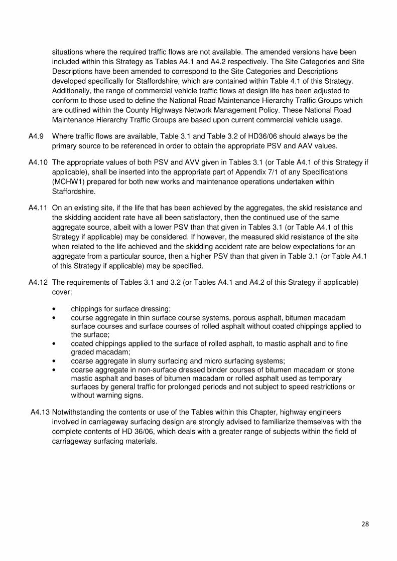
A4.12 The requirements of Tables 3.1 and 3.2 (or Tables A4.1 and A4.2 of this Strategy if applicable)
cover:
• chippings for surface dressing;
• course aggregate in thin surface course systems, porous asphalt, bitumen macadam surface courses and surface courses of rolled asphalt without coated chippings applied to the surface;
• coated chippings applied to the surface of rolled asphalt, to mastic asphalt and to fine graded macadam;
• coarse aggregate in slurry surfacing and micro surfacing systems;
• coarse aggregate in non-surface dressed binder courses of bitumen macadam or stone mastic asphalt and bases of bitumen macadam or rolled asphalt used as temporary surfaces by general traffic for prolonged periods and not subject to speed restrictions or without warning signs.
A4.13 Notwithstanding the contents or use of the Tables within this Chapter, highway engineers
involved in carriageway surfacing design are strongly advised to familiarize themselves with the
complete contents of HD 36/06, which deals with a greater range of subjects within the field of
carriageway surfacing materials.

29
Notes:
1. This table is only to be used for new works and maintenance operations within Staffordshire where lack of required traffic flows precludes the use of Table 3.1a and 3.1b contained within IAN 156/12.
2. Sites are grouped according to their general character and traffic behaviour. The Investigatory Levels (IL) for specific Site Categories of site are defined in Table 4.1. The IL to be used here is that which has been allocated to the specific site on which the material is to be laid, as determined by following the procedures contained in Chapter 4.
3. Dual carriageway slip roads may fit in a number of categories depending on their layout. For example, a free-flowing section close to the main line would be in Category B/C whereas the end of an off-slip approaching a give way line or the point at which a queue develops would be in Category Q/K. Some slip roads with

30
gradients may be in Category G1/G2. Use the most appropriate Site Category from Table 4.1 that was used to determine the Investigatory Level.
4. Where ‘68+’ material is listed in this Table, none of the three most recent results from consecutive tests relating to the aggregate to be supplied shall fall below 68. See HD 36/06 paragraph 3.21.
5. Throughout this table, HFS means specialized high friction surfacing; incorporating Calcined Bauxite aggregate, conforming to Clause 924 of the Specification (MCHW1) will be required. See Chapter 11.
6. For sites in Categories R, G1, G2, S1, S2, S3, any PSV in the range given for each traffic level may be used for any IL and should be chosen based on local experience of material performance. In the absence of other information, the values given for the appropriate IL and traffic level should be used.
Table A4.1 Minimum PSV of Chippings, or Coarse Aggregate in unchipped surfaces, for use on
highways within Staffordshire where current Traffic Flows are not available.
Road Hierarchy Traffic Groups 07 – 04 03 02 01
Current Traffic Usage – cv/each
direction/day (<250) (250-750) (750–1250) (>1250)
Maximum AAV for chippings for hot
rolled asphalt and surface dressing,
and for aggregate in slurry and micro
surfacing systems.
14 12 12 10
Maximum AAV for aggregate in thin
surface course systems, exposed
aggregate concrete surfacing and
coated macadam surface course.
16 16 14 12
Notes:
1. This table is only to be used for new works and maintenance operations within Staffordshire where
lack of required traffic flows precludes the use of Table 3.2 contained within HD 36/06.
2. For carriageways within Road Hierarchy Traffic Groups 02 to 07, aggregate of higher AAV may be used
where experience has shown that satisfactory performance is achieved by an aggregate from a particular
source.
3. The maximum AAV requirement for porous asphalt is specified in Clause 938 of the Specification
(MCHW 1).
Table A4.2 Maximum AAV of Chippings, or Coarse Aggregate in unchipped surfaces, for use
on highways within Staffordshire where current Traffic Flows are not available.

31
Annex 5
Improving Skid Resistance In Staffordshire
Early Life Skid Resistance
General
A5.1 HD 28/04 does not contain procedures to mitigate the risks associated with the reduced early life
skid resistance of some newly laid surfacing materials. The Highways Agency published an
Interim Advice Note 49/03 to address this issue, later superseded by IAN 49/13.
A5.2 Staffordshire have developed their own policy, for use on local authority maintained highways
within Staffordshire, to manage the potential problems associated with the reduced early life skid
resistance of some newly laid Surfacing Course materials.
A5.3 The early life skid resistance of Stone Mastic Asphalt (SMA) Surfacing Course is a cause for
concern. This is due to the high binder content of the SMA materials used and the presence of
significant amounts of this bitumen at the surface of the carriageway after the laying of the
material. This surface bitumen may result in SMA skid resistance values measured in dry
conditions displaying similar values to those measured on existing trafficked material in wet
conditions and hence may result in SMA skid resistance values in wet conditions that are
significantly below the values required by this Strategy.
Use of Sealing Grit
A5.4 Staffordshire Highways Combined Specification contains a Contract Specific Additional Clause
AR 971. This Additional Clause details Staffordshire's 'Policy For Use of Stone Mastic Asphalt on
County Roads', and also provides information on the use of sealing grit to establish
Staffordshire's requirement for the provision of early life skid resistance.
A5.5 The application of coated sealing grit conforming to the requirements of BS 4987: Part 1, Clause
7.9, 0-4mm sealing grit, on the generic SMA Surfacing Course specified for use within
Staffordshire, has been found to provide a significant improvement in early life skid resistance
and therefore its use should be specified on all carriageways where SMA is to be laid.
A5.6 The rate of spread of the sealing grit should be approximately 0.5 to 0.7 kg/sq.m and the material
should be applied to the hot mat during the compaction process. Mechanical means should be
used to apply the grit to ensure an even rate of spread and to avoid the occurrence of excessive
localized accumulations of material.
A5.7 It is recognised that the application of grit will reduce texture depth to some degree, however, a
monitoring regime of gritted SMA carried out by Staffordshire Highways Laboratory, on both high
speed roads and low speed roads and roundabouts, indicates that it is unlikely that texture
depths will be reduced below those levels required to provide adequate levels of skid resistance.
A5.8 On sites where sealing grit has been applied, warning signs will not normally be required and skid
resistance tests need only be carried out where there is a recent skid related accident history, or
where a previously higher level of skid resistance existed which has come to be relied upon by
road users.

32
High Friction Surfaces
General
A5.9 Although all roads require an appropriate level of skid resistance, there are some locations that
may require a higher level of skid resistance than others to increase the levels of safety for the
highway user.
A5.10 High Friction Surface (HFS) systems can be highly effective when used to increase the skid
resistance of a site, however they should only be installed in locations where its use is specified
within Table 3.1 of HD 36/06, or within Table A4.1 of his Strategy if the required traffic flows for
the site are not available.
A5.11 Additionally, and only in appropriate circumstances, the use of HFS may be targeted at specific
site’s, where there is an identified risk of accidents involving skidding, to produce benefits in the
form of a reduction in the number of vehicular accidents and their levels of severity.
A5.12 Typical locations for the installation of HFS systems are busy sites subject to high traffic densities
and sites where vulnerable highway users are present, such as on the approaches to pedestrian
crossings and signal controlled junctions. Roundabouts and other high risk situations such as
sharp bends or steep gradients or where there is a combination of both, are also locations that
may benefit from the use of HFS systems.
A5.13 Whilst it is accepted that HD36/06 requires a minimum HFS treatment length of 50m on the
approach to a hazard, it is also acknowledged HD36/06 has been developed for use on Trunk
Roads. Local authority maintained highways generally carry lower levels of traffic and may
therefore, be considered lower risk. Where HFS is to be used on LHA highways within
Staffordshire, an assessment of the proposed location may be carried out, and a record should
be retained, to determine whether 50m of HFS is required, or whether a shorter length may be
considered adequate.
A5.14 Design engineers should be aware that the ‘unrestricted’ use of HFS systems may raise the
safety level of the local highway environment and eventually the expectations of local highway
users, resulting in the transferral of the problem from the treated site to another location within
the same general locality.
A5.15 Over recent years, there has been an apparent willingness to specify the use of HFS systems at
locations where its installation cannot readily be justified in terms of accident reduction or the
requirements of HD 36/06. At these locations a risk based approach should be adopted when the
site is due for surface maintenance treatment to ascertain whether reinstatement of the HFS is
justified or whether a replacement surfacing material containing an aggregate with a Polished
Stone Value (PSV) that meets the requirements of HD 36/06 would be more appropriate.
A5.16 Professional engineering judgment, taking into account local experience and the accident history
of each site where a HFS system is proposed, should be used to consider which method is most
suitable for that particular site or whether a more cost efficient alternative may be more
appropriate. These alternatives include road safety measures such as improvements to road
markings, signs or street lighting, or the use of surface dressing materials with a high skid
resistant natural aggregate bonded with a binder capable of withstanding the braking forces
generated at the site.

33
A5.17 There may be a limited number of sites where the use of HFS systems is not warranted by
reference to Table 3.1 or Table A4.1, but it is recognized that there may be advantages to be
gained by the use of a surfacing system that provides the material properties required for the site
together with a visual impact similar to that provided by a HFS system. In these cases the options
include;
• The use of a Surface Course material which contains a coloured aggregate or coloured pre-coated chippings. The binder of this material may additionally contain a coloured pigment;
• Application of a surface dressing containing coloured chippings.
A5.18 There are alternative methods of achieving similar high levels of surface friction at specific sites
that may be more beneficial when whole life costs are considered:
• application of a surface dressing containing a 70+ PSV natural aggregate at high risk / high stress sites, using a polyurethane resin binder to ensure that the bond between the road surface and the dressing is of sufficient strength to prevent the dressing being stripped from the road surface;
• Installation of a Surface Course containing a 70+ PSV natural aggregate.
A5.19 Requirements for the use of specialized HFS systems, and Surface Courses and Surface
Dressing containing 70+PSV aggregates, must be included within Appendix 7/1 of any Contract
documentation produced for new or maintenance Works on Staffordshire's highway network and
this information forwarded to the Asset Management Section.
Materials and Workmanship
A5.20 Although HAPAS approval is not required for the use of specialized HFS systems on local
authority maintained highways (it is required for use on Trunk Roads and Motorways),
Staffordshire specifies that the systems used on its highways adhere to the requirements of
MCHW Clause 924; High Friction Surfaces. This requires the system to have a current British
Board of Agrément HAPAS Roads and Bridges Certificate and to be installed by a Contractor,
approved by the BBA and the Certificate Holder, to install that system.
A5.21 Natural aggregate that has a PSV over 60 is regarded as a high skid resistant aggregate, but
aggregates with a PSV over 65 are needed for particularly high stressed sites.
A5.22 HFS is a term that describes the specialized group of road surface treatment systems that are
applied as a topping to the road surface and utilize Calcined Bauxite as the aggregate that
provides the specified minimum 70+ PSV.
A5.23 Specialized HFS systems are expensive, both to install and maintain, and on more heavily
trafficked sites the durability of different surfacing systems can vary greatly, therefore it is
important to consider the whole life costs of the proposed works and to ensure that the correct
system is used taking into account the volume of traffic predicted for the site for the expected life
of the system.
A5.24 The Calcined Bauxite aggregate used in specialized HFS systems exhibits very high PSV and
very low Aggregate Abrasion Value's (AAV), although the PSV does alter according to the
source.

34
A5.25 There are several sources of Calcined Bauxite on the market with densities varying from 2.6 to
3.4, dependent upon source. Density is a good indication of the PSV of the Calcined Bauxite,
with high density indicating a high PSV.
A5.26 Test certificates should be requested to ensure that the Calcined Bauxite used has an
appropriate PSV.
A5.27 Specialized HFS systems usually use a form of resin rather than bitumen to hold the aggregate to
the road surface. There are two types:
1. Cold applied processes using a thermosetting, epoxy, polyurethane or methyl
methacrylate resin. They are supplied as separate components that when mixed together
undergo a chemical reaction that produces some heat and sets hard after a number of
hours.
2. Hot applied process where the Calcined Bauxite and the thermoplastic resin, which is
supplied in a granular form, are supplied premixed. The material is heated and screeded
out onto the road surface where it cools and hardens.
Measurement of Skid Resistance Values
A5.28 Staffordshire does not specify an 'end product' SRV for specialized HFS systems because it is
considered unlikely that a currently certified system, installed by an Approved Contractor, will not
be fit for purpose.
35
Annex 6
STAFFORDSHIRE COUNTY COUNCIL – PLACE
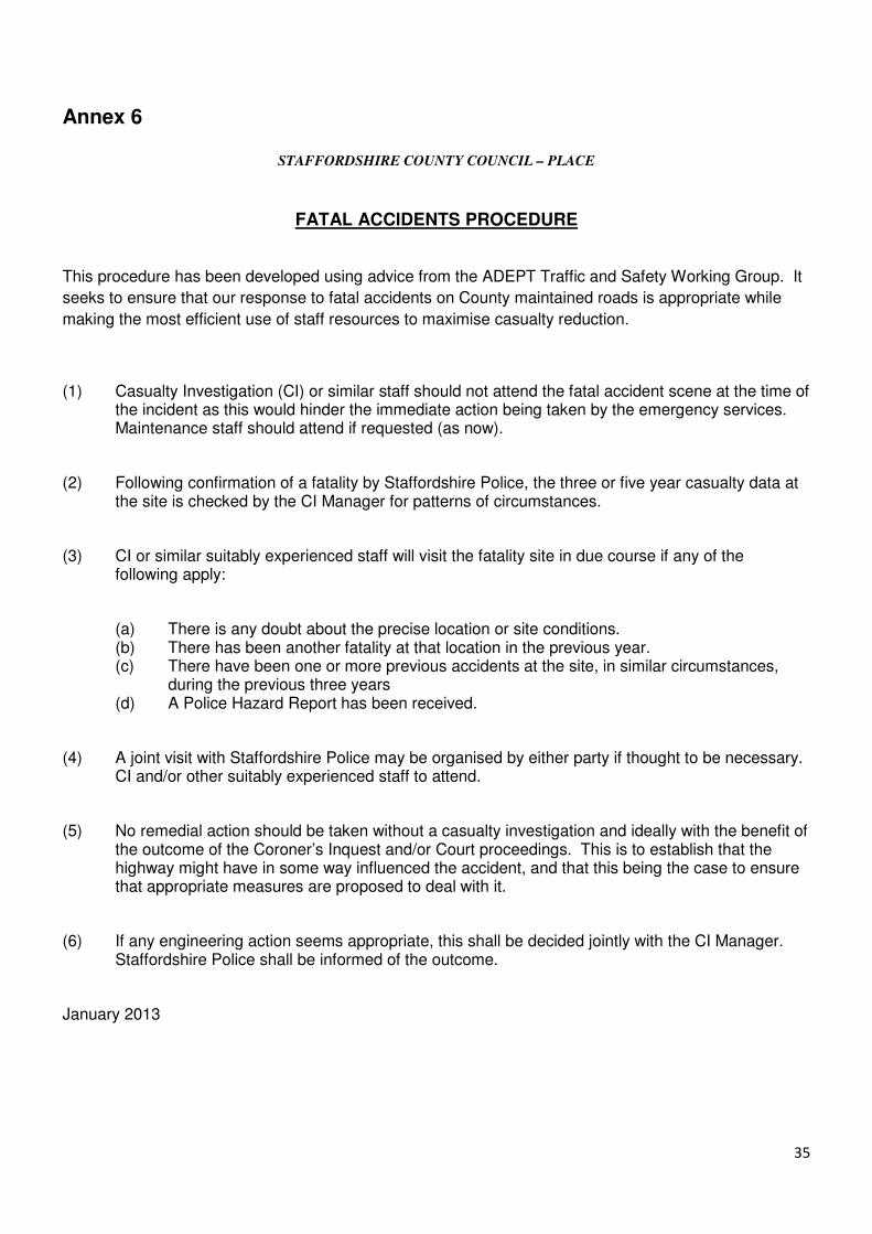
FATAL ACCIDENTS PROCEDURE
This procedure has been developed using advice from the ADEPT Traffic and Safety Working Group. It
seeks to ensure that our response to fatal accidents on County maintained roads is appropriate while
making the most efficient use of staff resources to maximise casualty reduction.
(1) Casualty Investigation (CI) or similar staff should not attend the fatal accident scene at the time of the incident as this would hinder the immediate action being taken by the emergency services. Maintenance staff should attend if requested (as now).
(2) Following confirmation of a fatality by Staffordshire Police, the three or five year casualty data at the site is checked by the CI Manager for patterns of circumstances.
(3) CI or similar suitably experienced staff will visit the fatality site in due course if any of the following apply:
(a) There is any doubt about the precise location or site conditions. (b) There has been another fatality at that location in the previous year. (c) There have been one or more previous accidents at the site, in similar circumstances,
during the previous three years (d) A Police Hazard Report has been received.
(4) A joint visit with Staffordshire Police may be organised by either party if thought to be necessary. CI and/or other suitably experienced staff to attend.
(5) No remedial action should be taken without a casualty investigation and ideally with the benefit of the outcome of the Coroner’s Inquest and/or Court proceedings. This is to establish that the highway might have in some way influenced the accident, and that this being the case to ensure that appropriate measures are proposed to deal with it.
(6) If any engineering action seems appropriate, this shall be decided jointly with the CI Manager. Staffordshire Police shall be informed of the outcome.
January 2013

36
Annex 7
FOOTWAYS, CYCLEWAYS, PAVED SURFACES AND VULNERABLE USERS
General
A7.1 This Chapter deals with the maintenance of adequate levels of slip resistance and skid resistance
on footways, cycleways and other paved surface areas, which may include Byways Open to All
Traffic (BOAT).
A7.2 Slip resistance is defined as the ability to resist relative movement between a pedestrian foot and
the trafficked surface.
A7.3 Skid resistance is defined as the ability to resist relative movement between a vehicle tyre and
the trafficked surface.
A7.4 Footways are designed for pedestrian usage, however there are locations where motorized and
non-motorized vehicular movements also occur therefore these surfaces are required to provide
both slip resistance and skid resistance.
A7.5 A cycleway that is located upon a carriageway will have the same Investigatory Level as the
carriageway, and therefore its skid resistance value will be maintained at the same level as the
carriageway.
A7.6 A cycleway that is located either adjacent to, and is structurally an integral part of a footway, or is
separate to, or remote from any footway or highway, may be treated in a similar fashion to
bituminous footways to provide the same levels of skid resistance.
A7.7 A BOAT does not generally have a paved surface, however there are a small number within the
County that do. In these cases, a site specific assessment should be carried out to establish the
type of vehicular usage (if any) and a determination made on what (if any) the appropriate
surfacing material / aggregate PSV or surface treatment should be.
Inspection and Testing
A7.8 The establishment of an effective regime of inspection, assessment and recording is a crucial
component of highway maintenance. Regular inspections are necessary to monitor the condition
of all elements of the network in order that any defects can be identified and an informed
engineering judgment can be made about the strategy to be adopted to rectify any deficiencies,
including inadequate slip / skid resistance values. If the deterioration in slip / skid resistance
values presents a safety hazard to users, then maintenance becomes essential.
A7.9 The frequency of inspections is as detailed within Staffordshire's 'Highway Safety Inspection
Code of Practice'.
A7.10 'Well Maintained Highways' details three categories of inspection for highways, Safety
Inspections, Service Inspections, and Condition Surveys.
A7.11 Safety Inspections are designed to identify all defects likely to create a danger or inconvenience
to users of the highway network. Safety Inspections for footways, cycleways and other paved
surfaces will identify defects such as potholes, broken flags, rocking flags, missing pavers or
flags, trips, ruts or depressions.

37
A7.12 Service Inspections are more strongly focused on ensuring that the network meets the needs of
the user and comprise more detailed specific inspections of particular highway elements. ‘Well
Maintained Highways’ allows Service Inspection frequency for footways and cycleways to be
determined locally and accepts that they may be undertaken in conjunction with Safety
Inspections or Condition Surveys.
A7.13 Presently within Staffordshire, Safety Inspections and Service Inspections are carried out
concurrently by Area Highway Inspectors. Any locations on the network where it appears that
there is a reduced level of slip / skid resistance will be identified during these inspections and
prioritized for inclusion in the forward works programme for surface treatment.
A7.14 Non compliance by utility companies undertaking reinstatements works has been identified as
one area where an unacceptable reduction in slip / skid resistance values may occur. The
Network Management Unit of Place will be issuing utility companies who operate within
Staffordshire with a formal 'Prior Notification' of Staffordshire's 'local custom and practice'
requisite for the use of 45 PSV aggregates for Surface Course reinstatements in pedestrian
areas and on cycle tracks as outlined within the Highway Authorities & Utilities Committee
(HAUC) Code of Practice - Specification for the Reinstatement of Openings in Highways (DfT et
al, 2002): Chapter 8:S8.1.1 (2). A robust inspection regime, together with adherence to the
requirements of the HAUC Code, will ensure that slip / skid resistance values of reinstated
surfaces of footway / cycle way / other paved areas is appropriate to that of the existing surfacing
following reinstatements carried out after utility works.
A7.15 Should any footway, cycleway or other paved area within Staffordshire, be brought to the
attention of Place due to third party complaints of inadequate slip / skid resistance values,
Staffordshire Highways Laboratory will be requested to undertake Pendulum tests at the location
to assess whether an appropriate level of slip / skid resistance exists. Any locations on the
network where the test results indicate that there is a reduced level of slip / skid resistance that
could lead to a greater slip / skid risk for highway users, will be identified and prioritized for
inclusion in the forward works programme for surface treatment.
Surfacing Materials
A7.16 Loss of surface texture due to normal foot or tyre traffic cannot be eliminated, but it can be
reduced to an acceptable level by using the appropriate materials for the wear properties
required. Material that is well suited to its situation, allows texture loss due to wear to be
balanced by a texture increase due to weathering.
A7.17 Pedestrian traffic has the potential to polish footway surfaces to levels where safety can be
compromised. The surface of a footway should have adequate slip / skid resistance and abrasion
resistance and must not become difficult for pedestrians to walk on when wet.
A7.18 The most commonly used types of surfacing for footways are bituminous materials (bitumen
macadam or hot rolled asphalt), precast concrete (PCC) pavers and flags or clay pavers. It is not
recommended that in situ concrete is used due to the difficulties caused when works by Statutory
Undertakers are carried out. Natural stone flags, cobbles and setts are not commonly used within
Staffordshire as they tend to be both expensive and difficult to lay, although there are some
locations where they have been used.

38
A7.20 Engineers should ensure that, for new construction and maintenance operations on footways, a
minimum PSV of 45 is specified for aggregates used in bituminous Surface Course materials and
in maintenance surface treatments, as detailed within Staffordshire Highways Combined
Specification (this will exclude Limestone as a permissible surfacing aggregate). This
requirement should be included within any applicable Appendices of any Contract documentation
produced for Works on Staffordshire's highway network. If this principle is adhered to, inadequate
slip / skid resistance and abrasion resistance are unlikely to be a problem on bituminous
surfacing materials.
A7.21 It is unlikely that the slip / skid resistance of PCC products used for footways will be inadequate.
Under normal conditions of use, PCC pavers / flags provide satisfactory slip / skid resistance
during the working life of the product, provided they are subjected to normal maintenance and
unless a major proportion of aggregates which polish excessively have been exposed on the
upper face.
A6.22 Care should be taken when specifying clay pavers as in areas of heavy pedestrian use, clay
pavers can become slippery when wet. The resistance to polishing of clay pavers is expressed as
a Polished Paver Value (PPV). As a first approximation PPV is equivalent to PSV for aggregates.
A minimum PPV of 45 should therefore be specified for general use.
Surface Treatments
A7.23 A surface treatment has two objectives, firstly, to seal the surface to prevent deterioration and
secondly, to provide a non-slip surface. It also has the advantage of restoring a consistent
appearance to the surface.
A7.24 Slurry surfacing: Slurry surfacing is used to stabilize the surface area, to ensure that it is
impermeable and is of a consistent appearance. Slurry surfacing includes a 3mm to 6mm, well
graded aggregate that provides a textured surface that restores slip / skid resistance to surfaces
that have become smooth.
A7.25 Surface dressing: Surface dressing is a thin veneer suitable for restoring slip/skid resistance
values, arresting deterioration and restoring waterproofing properties of the surface.
A7.26 Retexturing: Re-texturing of modular surfaces that have become slippery due to heavy
pedestrian traffic can be undertaken by various methods, these include scabbling, sand or shot
blasting, high pressure water jetting or application of a weak acid. If a section of concrete footway
becomes polished due to heavy pedestrian traffic it can also be retextured by shot blasting.
A7.27 Washing of the surface: In feature areas it may be necessary to wash the walking surface. This
is done by adapted small suction sweepers using hot water with added detergent. In addition to
the cleaner appearance there is a significant improvement in the slip / skid resistance values.
Specialized Surfacing Systems
A7.28 Specialized high skid resistant surface systems (similar to the HFS systems used on
carriageways) may be used to treat pedestrian / cycle way surfaces in locations where specific
problems are encountered. In locations where conflict with other highway users may occur e.g.
across the mouth of T-junctions, these specialized systems may contain a coloured pigment. In

39
these situations, a finer particle 60 PSV aggregate is used and the surfacing tends to be referred
to as anti-slip or anti-skid surfacing.
A7.29 There are also a variety of proprietary products that can be painted onto the surface to increase
slip / skid resistance in problem areas such as steep slopes.
A7.30 Further guidance on slip / skid resistance is available in the County Surveyors Society
publication. “The Assessment of Slip Resistance in Paved Areas for use by Pedestrians and
Horse Riders” (Ref No. - ENG1-96).
HORSES AND HIGHWAY SURFACING
General
A7.31 Nationally, since the mid 1990’s, it is reported that there has been an apparent increase in the
numbers of horses slipping on the highway surface, this increase has been particularly apparent
since the year 2000.
A7.32 Historically there have been occasional reports of horses slipping on highway surfaces; however
these problems would have been rectified by local, routine maintenance. The increase in the
number of reports is attributed to the binder rich, negative texture thin surfacing materials,
generally reported as SMA, that have an increased binder film thickness on the surface of the laid
material.
A7.33 The County Surveyors Society (CSS) has worked with the British Horse Society (BHS) to
produce a Guidance Note for Highway Authorities - Horses and Highway Surfacing (Eng/3-05), to
deal with this issue. The Guidance Note deals with slipping by horses in the early life of
negatively textured Surface Course materials. A copy of this Guidance Note can be located on:
H:\General Information\Lab Technical Information
A7.34 The Guidance Note suggests that, in certain circumstances, alternative treatments to remove the
surface binder film on the Surface Course aggregate are carried out to increase the initial grip
between the steel shoe of the horse and the highway. The alternative treatments proposed are:
i/ During construction:
• application of grit. ii/ After construction:
• surface dressing;
• application of grit;
• application of hot grit;
• texturing by the use of wire brush or water jetting.
Procedure
A7.35 Staffordshire County Council presently apply coated grit during the laying process for all SMA
Surface Course materials used on the highway network within Staffordshire. SCC therefore
complies with the suggestions contained within the Guidance Note..

40
A7.36 At sites where 'Slippery Road' warning signs are in place, equestrian users will need to be aware
of these signs and follow the BHS advice contained within the Guidance Note that 'all horse
riders using the highway in any context must exercise their duty of care as a road user'.
Considerations should also be given to positioning the warning signs at locations where they are
visible to horse riders joining the highway from adjacent routes.
A7.37 In conjunction with the BHS, CSS helped to produce a standard form, 'Horse/Road Surface
Interface Incident Report Form', which is contained within the Guidance Note, a copy of which is
also appended to this Strategy (see Appendix 5). This Form can be used by BHS members to
report horse slipping problems on highways. The Incident Report Form is also located on the
BHS website at:
www.BHS.org.uk.
A7.38 Upon receipt of an incident report form, an investigation shall be undertaken.
This should include written documentation on:
• the condition of the surfacing;
• the type of surfacing;
• comments relating to the geometry of the highway;
• any additional information that may be considered relevant to the incident.
A7.39 Details will also be required on:
• the horse;
• the condition of the horse’s shoes;
• in the case of litigation farrier’s records will be required to assess the condition of the horse's shoes at the time of the incident.
A7.40 Any decisions following the investigation should be formally documented and the documentation
retained.

41
Appendix 1
Site Category Review - SRF1
Review Reference Number ……………………………
Road Number ……………………………
Existing Site Category ……………………………
Existing Investigatory Level ……………………………
New Site Category ……………………………
Description of Extents ……………………………
ASSESSOR ………………………………………
DATE ………………………………………

42
Appendix 2
On Site Investigation - SRF2
General Site Information
Site Investigation Reference Number
Road Name
Highest Speed Limit
Reason for Site Investigation
Road Number
Site Category
Greatest Level of Deficiency
No# of KSI Accidents
No# of Slight Accidents
Policy Signage Requirement
Date when the site was last surface treated
Current ATF
Site Visit
Date of Site Investigation
Investigating Engineer
General weather conditions during visit
Site Pavement
Current Surface Course Material
Is the pavement uniformly degraded
Is there Evidence of Mud/ Ponding /Blocked Gullies / Poor Drainage
Current Pavement Defects
On Site Considerations
Additional features at location that increase risk (Layout / Geometry / Vegetation)
Recent Evidence of Vehicles Accidents
Priorities clearly defined with visible markings, warning /direction signs
Traffic signals operating correctly and clearly visible
Recommendations
Is treatment recommended
Type of Treatment
Other recommendations
Are Warning Signs required above Policy Requirements / Why
Priority and timing of treatment
Additional Comments
Possible reason for low scrim value
Approved By
Date

43
Appendix 3
Signage Location Investigation - SRF3
Investigating Engineer
Site Investigation Number (YYYY-DIV-XXX)
Sign ID
Direction of Travel
Description of location
Signage Post Required
Size of Sign Required
Distance of Sign from Hazard
Additional Supplementary Plate Lettering
Date of Notification of Order
Erection Order Completion date
Inspected By
Appendix 4
Signage Removal - SRF4
Site Investigation Number (YYYY-DIV-XXX)
Sign ID
Date of Notification of Removal
Removal Completion Date
Inspected By

44
Appendix 5
BRITISH HORSE SOCIETY WEBSITE FORM
HORSE / ROAD SURFACE INTERFACE - INCIDENT REPORT FORM
Name:
Address:
Telephone number:
Date of incident:
Please give details of the incident (what happened?)
________________________________________________________________
_______________________________________________________
_______________________________________________________
_______________________________________________________
On what location did the incident happen? (Please specify Road number, name and location e.g.
outside house number 42)
________________________________________________________________
_______________________________________________________

45
Village/Town: County:
Did this stretch of road have a verge? Y/N:
If yes, please give details:
Did the incident occur on a gradient? Y/N: _______
Did the incident occur at a change of surface? Y/N: ________
What time of the day did the incident happen?
What were the weather conditions at the time of the incident? (wet, dry etc)
Were any other people / vehicles involved?
Were you riding the normal line or was there a reason to be elsewhere in the road?
_____________________________________________________
_______________________________________________________
Was normal control maintained or had the horse been “spooked” by other factors?
__________________________________________________________
_______________________________________________________

46
What road use experience does the rider have? _____________________
Have you had BHS training for road use with a horse? Y/N:
Were any injuries received by yourself? Y/N:
If yes, please give details:
Were any injuries received by your horse? Y/N:
If yes, please give details:
At the time of the incident did your horse have shoes fitted? Y/N: ____
If so, were you using road studs? Y/N: ____ If so, please specify the type (e.g. removable road studs, nails etc)
____________________________________________________________
Have you been in touch with the local Highways Authority or County Council
to verify the type of surface?
Y/N:
If yes, please give details of who, where and what:

47
Please give any further details that you feel may be relevant:
Signature: Date:
![Textila 2 2012revistaindustriatextila.ro/images/2020/3/Industria... · polyamide knitted scrim [9]. Knit Scrim material has the task to give the dimensional stability to sandwich](https://img.pdfslide.net/doc/110x75/5fdc75ff22e4b870962c09c1/textila-2-2012rev-polyamide-knitted-scrim-9-knit-scrim-material-has-the-task.jpg)