Embed Size (px)
Citation preview

1
Staged, High Pressure Oxy-Combustion Technology: Development and Scale-Up
DE-FE0009702
Richard Axelbaum
Energy, Environmental and Chemical Engineering
Washington University in St. Louis
2017 NETL CO2 Capture Technology Project Review Meeting
Aug. 25, 2017
Project Overview
2
Design and build a laboratory-scale facility and conduct laboratory-
scale experiments and complimentary modeling that address the
technical gaps and uncertainties addressed in Phase I.
Advance SPOC technology to TRL-5.
Funding
Project Objectives: Phase II
10/01/2012 - 09/30/2017 (extended)
Project Performance Dates
Total project (Phases I & II): $5,243,789DOE share: $4,137,184
Cost share: $1,106,614
Project ParticipantsWashington University – Lead: SPOC development, experimentsEPRI – Technology evaluation, end-user insight, corrosionORNL – Corrosion study

Technology Background
3

4
• The requirement of high pressure CO2 for sequestration enables pressurized combustion as a tool to increase efficiency and reduce costs.
• Benefits of Pressurized Combustion– Recover latent heat in flue gas improved efficiency & cost
– Latent heat recovery can be combine reduced cost
with integrated pollution removal
– Reduce gas volume reduced equipment size
– Avoid air-ingress reduced CO2 purification costs
– Higher partial pressure of O2
– Optically dense atmosphere improved control of radiation HT
Pressurized Oxy-Combustion

5
• Optimizing use of radiation to minimizing heat transfer surface area
• Minimizing recycled flue gas (RFG)• Minimizing equipment size • Utilizing modular boiler construction
Improve capital costs by:
Improve operating costs by:
• Maximizing plant efficiencyo Low FGRo Dry feedo Minimizing oxygen requirements
• Utilizing “lead chamber” process for SOx & NOx removal• Increasing performance of wet, low BTU fuels
Key Features:
Motivation for SPOC

FGR
BFW
Coal Feeding
Neutralizer
Steam
Pressurized Oxygen
Coal
Return
CO2 Product
Water
LPFWTo SC
FGR
DCC+
de-&
de-
SOx
NOx
FGR
Bottom Ash
BoilerI
BoilerII
BoilerIII
Bottom Ash
Bottom Ash
Fly Ash
Economizer
Particulate Filter
ASUAir
CPUSteamSteam
For a 550 MWe power plant with > 90% CO2 capture
6
SPOC Process Flow Diagram
Modeling parameters from DOE/NETL Guidelines
courtesy of EPRI

FGR
BFW
Coal Feeding
Neutralizer
Steam
Pressurized Oxygen
Coal
Return
CO2 Product
Water
LPFWTo SC
FGR
DCC+
de-&
de-
SOx
NOx
FGR
Bottom Ash
BoilerI
BoilerII
BoilerIII
Bottom Ash
Bottom Ash
Fly Ash
Economizer
Particulate Filter
ASUAir
CPUSteamSteam
For a 550 MWe power plant with > 90% CO2 capture
7
SPOC Process Flow Diagram
Modeling parameters from DOE/NETL Guidelines
courtesy of EPRI

8
a. Gopan, A. et al. (2014) Applied Energy, 125, 179-188.
b. Hagi, H.,et al. (2014). Energy Procedia, 63, 431-439.
Plant Efficiencies
25% improvement in plant efficiency over first-
generation oxy-combustion

Technical Approach/Project Scope
9

Work Plan
10
Tasks
1. Project management
2. Design, fabrication and installation of high pressure combustion furnace
3. High pressure combustion experiments (heat flux, temp, ash, deposition)
4. Materials corrosion studies (high O2 and SO2 environments)
5. Modeling direct contact cooler
6. Re-evaluation of burner/boiler design
7. Update process model and techno-economic analysis

11
• Proof of concept demo of coal combustion under SPOC conditions.
• Improved understanding of radiation heat transfer in pressurized oxy-combustion conditions
• Improved understanding of ash formation/deposition mechanism in pressurized oxy-combustion conditions
• Knowledge of performance of boiler tube materials under SPOC conditions
• Improved estimate of SOx, NOx removal efficiency in direct contact cooler
• Reduced uncertainty and contingencies improved COE
Projected Phase 2 Outcomes

Progress and Current Status:
12

Key Considerations for Improved Low-Recycle Pressurized Oxy-Combustion Burner-Combustor
13
• High pressure
o Pressure vessel – cylindrical: high aspect ratio.
o Requires distribute heat release.
o Requires control of soot formation.
• Low-recycle (high T flame)
o Avoid flame impingement.
o Avoid excessive heat flux
o Control oxygen concentration near boiler tubes.
o Control soot formation.
• Minimize ash deposition (fouling & slagging).
• Ensure resilience to variations in flow conditions.
• Obtain high turn-down operation.
Courtesy of Phil SmithU of Utah

Key Considerations for Improved Low-Recycle Pressurized Oxy-Combustion Burner-Combustor
14
• High pressure
o Pressure vessel – cylindrical: high aspect ratio.
o Requires distribute heat release.
o Requires control of soot formation.
• Low-recycle (high T flame)
o Avoid flame impingement.
o Avoid excessive heat flux
o Control oxygen concentration near boiler tubes.
o Control soot formation.
• Minimize ash deposition (fouling & slagging).
• Ensure resilience to variations in flow conditions.
• Obtain high turn-down operation.
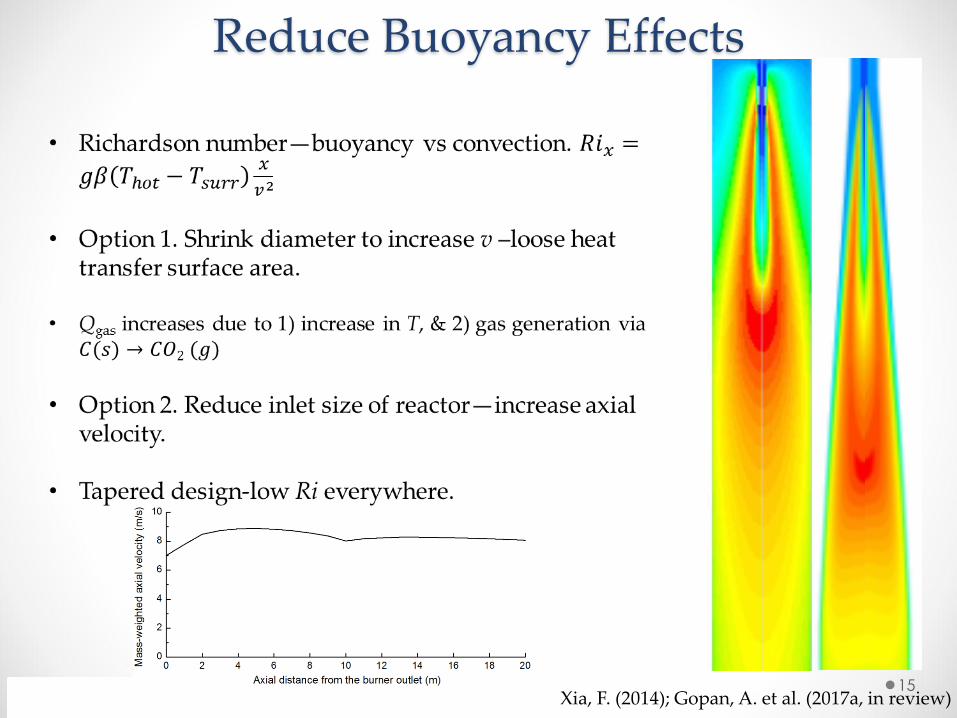
Reduce Buoyancy Effects
15Xia, F. (2014); Gopan, A. et al. (2017a, in review)
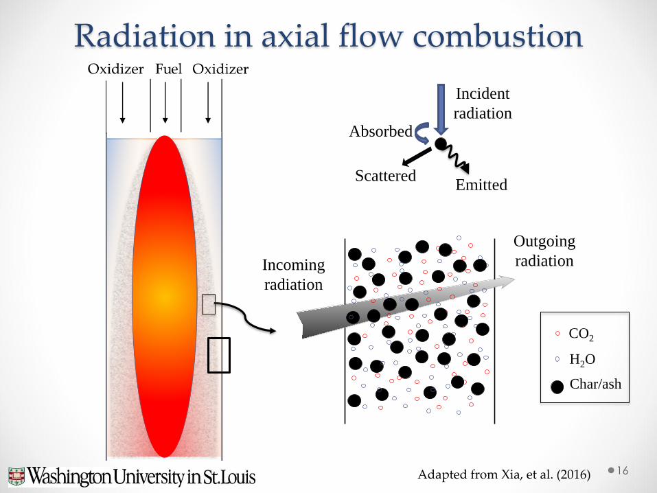
Radiation in axial flow combustion
16
Incoming
radiation
Outgoing
radiation
H2O
CO2
Char/ash
Scattered
Incident
radiation
Emitted
Adapted from Xia, et al. (2016)
Absorbed

• Optically dense medium.
• Wall heat flux only dependent on the temperature distribution in the radiation penetration layer (RP).
Very high core temperatures acceptable if temperature in RP
controlled
17
Hot region
x : Distance from the wall
T : Temperature
τw : Optical thickness from the wall
T
τw
τw= 2.3
Radiation
penetration layer
x
x
Cold Reactor
wall
Radiative Trapping
At high pressure:
(τw= 2.3; transmissivity 10%)
Gopan et al. (2017a in review); Xia et al. (2016)

Burner/Boiler Design
45.3 m10 m
18Gopan et al. (2017a in review)

Burner/Boiler Design
45.3 m10 m
19Gopan et al. (2017a in review)
> 3 %-pts.

20
Central-Oxygen Burner – Flame ShapesThree main flame shapes with an over-ventilated triaxial flame:
AcceptableBut low central oxygen => more recycle
UnacceptableFlame impingement – high heat flux
Preferable solution
Gopan et al. (2017a in review)

21
High temperature in the core of the boilerBut, low temperature in the radiation penetration layer.
SPOC Boiler Results
SO [O2] = 35 vol.%
Refractory wall
Gravity
Conical
frustum

22
High temperature in the core of the boilerBut, low temperature in the radiation penetration layer.
SPOC Boiler Results
SO [O2] = 35 vol.%
Refractory wall
Conical
frustum
Gravity

23
Effect of Mixing – Central Oxygen FlowR
adia
tive h
eat
flux (
kW
/m2)
Gravity

Soot Comparison – Normal vs. Tri-axial
24
Quench/dilution N2
To SMPS
Total # concentration:
Normal: 1x10⁶ #/cm3
Tri-axial: 1x10⁴ #/cm3
Configuration
IO Flow
(m3/h)a
(pure oxygen)
Fuel stream
flow (m3/h)a
Fuel stream
[CH4] (%v)
SO Flow
(m3/h)a
SO Stream
[O2] (%v)SRIO SRTotal
Normal 0 3.1 62.7 19.7 45.5 0 2.3
Triaxial 2.7 3.1 62.7 17.0 36.8 0.7 1.6

Eddy impaction & thermophoresis dominant
Particle Deposition in Conventional and SPOC Boilers
High-mixing traditional systems
Inertial impaction is dominant
Wall-fired T-fired
Courtesy of Phil SmithU of Utah
Low-mixing, axial flow SPOC

• Non-dimensional deposition temperature1
Deposition temp. in non-isothermal flows
26
Edge of viscous sublayerS+ > 10 S+ < 1
, *g p g d w
d
c u T TT
q
[1] B. Kader 1981
( , )d TT f S S
S+ determines residence time
ST+ determines cooling speed
Zone I
Zone II
Zone III
ST+NupCC/S+
Tg = 500 K

SPOC particle deposition
27
• CFD simulation results
• The average particle impact rate in the SPOC boiler is an order of magnitude lower than that in conventional PC boilers1
• The temperatures of all ash deposits are lower than 850 oC, which is much lower than the ash fusion temperature. Slagging is unlikely.2
Average impact rate for conventional boilersAverage impact rate for SPOC
1 Wang, H., & Harb, J. N. (1997) Progress in Energy and Combustion Science, 23(3), 267-282.
2Yang et al. (2017 in prep); Gopan et al. (2017c in prep);

Pressurized Oxy-Combustion Facility
28
U.S.-China CERC CCCUDOE
Objectives:
• ~100 kW test under SPOC conditions
• Wide operating range, pressure 1-15 bar, oxygen concentration 21~100%
Capabilities:
• Visual access of flame shape
• Laser diagnostics
• High-speed, high-resolution camera
• Heat flux sensors
• Pressurized sampling (gas & particle)o CEMS, FTIR, SMPS, ELPI

Pressurized Oxy-Combustion Facility
29

High-Speed Video

SPOC Status
Next steps:
o U.S.-China Clean Energy Research Center (CERC-ACTC)• Increasing scale of existing facility
• Advancing technology to Pre-FEED for pilot scale facility
o Integrated Flue Gas Purification and Latent Heat Recovery for Pressurized Oxy-Combustion, DE-FE0025193
• Will discuss in next talk
o Enabling Staged, Pressurized Oxycombustion: Improving Flexibility and Performance at Reduced Cost DE-FE0029087• EPRI (Lead), Doosan Babcock, Air Liquide and WUSTL
31

Development Roadmap
32
2012 2014 2016 2018 2020 2022 2024 2026
>100 MW
10 MW
0.1-1 MW
Full Scale
Pilot Scale
Lab Scale
Process &
Techno-Econ
Models
CFD Boiler
Design
Dynamic
Process
Modeling
LES
Simulation
Pre-FEED
Materials
Evaluation
Pollutant
Removal Demo
Commission
Test
Facility

AcknowledgementsWash U: A. Gopan, F. Xia, B. Kumfer, Z. Yang, A. Adeosun,
D. Khatri, T. LiEPRI: J. Phillips, D. Thimsen, S. Hume, S. Kung, J. ShingledeckerORNL: B. Pint
Funding: U.S. Department of Energy: Award # DE-FE0009702Advanced Conversion Technologies Task Force, WyomingConsortium for Clean Coal Utilization, Washington University in St. Louis
Sponsors: Arch Coal, Peabody Energy, Ameren
U.S. Government Disclaimer
This report was prepared as an account of work sponsored by an agency of the United States Government. Neither the United States
Government nor any agency thereof, nor any of their employees, makes any warranty, express or implied, or assumes any legal
liability or responsibility for the accuracy, completeness, or usefulness of any information, apparatus, product, or process disclosed,
or represents that its use would not infringe privately owned rights. Reference herein to any specific commercial product, process, or
service by trade name, trademark, manufacturer, or otherwise does not necessarily constitute or imply its endorsement,
recommendation, or favoring by the United States Government or any agency thereof. The views and opinions of the authors
expressed herein do not necessarily state or reflect those of the United States Government or any agency thereof.
33