Embed Size (px)
Citation preview
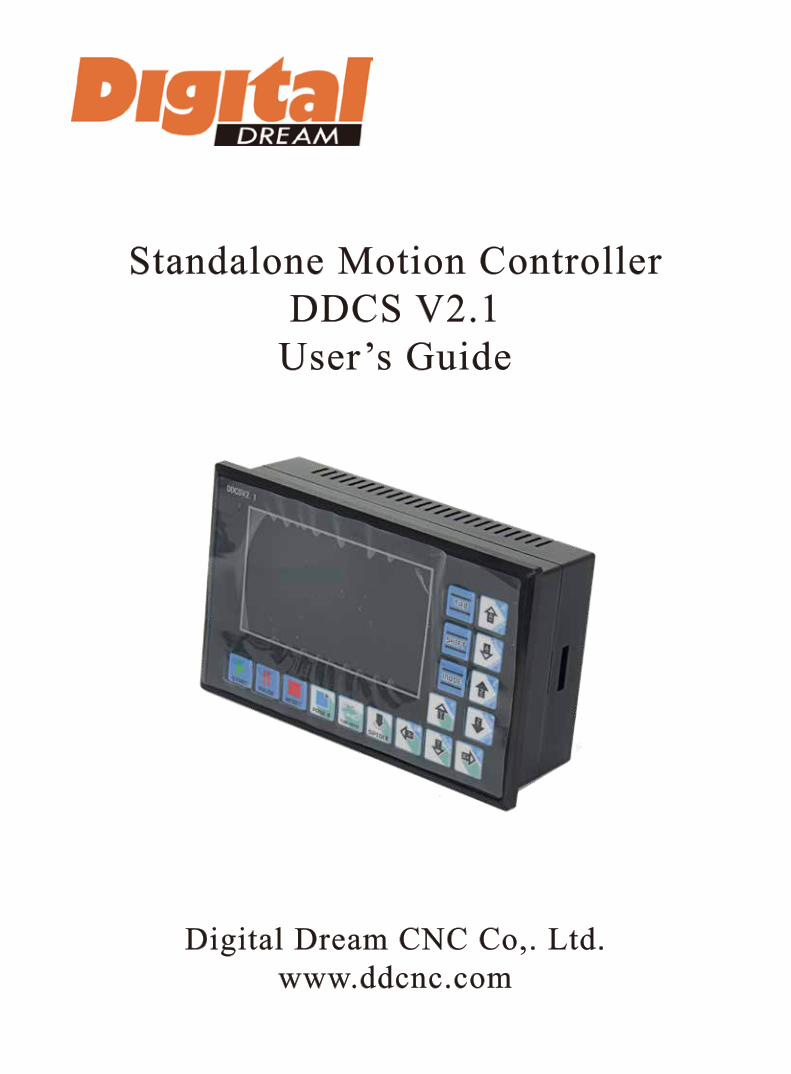
Standalone Motion ControllerDDCS V2.1
User’s Guide
Digital Dream CNC Co,. Ltd.www.ddcnc.com
1 DDCS V2.1 Controller Introduction
1) 16 opto isolated digital inputs
2) 3 opto isolated digital outputs
3) Analog spindle control 0-10V spindle control (can be modified as PWM output)
4) 4 axis motor control, max 500KHz per axis
5) ARM9 main control chip
6) FPGA core algorithm chip
7) 4.3 inches TFT screen, resolution ratio: 480x272
8) 17 operation keys
9) 18V-32V power input, minimum 0.5A
10) USB flash disk support for G code file input
11) 1GB internal memory
12) MPG port for our MPG with digital display. Many other MPG’s also supported
13) Jog function for each axis (continuous, step, defined distance
14) Support the operation of quickly specify the running position
15) Support for “Power Cut” recovery. Data is automatically saved.
Digital Dream has a 20 years history in the numerical control industry, specializing in the research, devel-opment and production of various CNC (Computer Numerical Control) systems. Digtital Dream aims to combine high quality and high reliability with affordability. We produce 1 axis to 6 axes CNC system.
The DDCS V2.1 is a 4 axis motion controller for stepper and servo systems. We are very proud of this product, it combines great power with a tiny footprint and is easy to use. After a very short time you will be familiar with the functions and this manual will help you. The highest output pulse per axis is 500KHz. The pulse width is adjustable (refer to driver manual). The control period of each position is only 4 milliseconds. This provides high control precision for stepper motors and servo motors.
The DDCS V2.1 numerical control system adopts the ARM+FPGA design framework. ARM controls the human-computer interface and code analysis and the FPGA provides the underlying algorithms and creates the control pulse. This guarantees reliable control and easy operation. The internal operating system is Linux based.
The panel layout structure of the DDCS V2.1 is very rational to save space. All operations are controlled by only 17 keys and a comprehensive G code set is supported.
The DDCS V2.1 can be used for many styles and types of CNC machines. Lathes, Routers, Pick&Place and Mills are just a few examples. The DDCS V2.1 operates as a Stand Alone system without the need of a comput-er. This guarantees high precision, accuracy and reliability. The interface, even very comprehensive, can be learned in a very short time.
1.1 Introduction of Product
1.2 Performance parameter of the Digtital Dream DDCS V2.1
Page -1Digtital Dream 4 Axis Motion Controller DDCS V2.1 User’s Manual
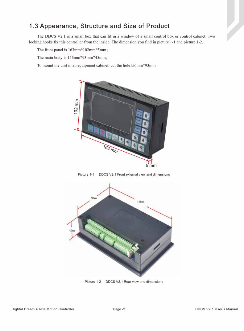
The DDCS V2.1 is a small box that can fit in a window of a small control box or control cabinet. Two locking hooks fix this controller from the inside. The dimension you find in picture 1-1 and picture 1-2.
The front panel is 163mm*102mm*5mm;
The main body is 156mm*93mm*45mm;
To mount the unit in an equipment cabinet, cut the hole156mm*93mm
1.3 Appearance, Structure and Size of Product
Picture 1-1 DDCS V2.1 Front external view and dimensions
Picture 1-2 DDCS V2.1 Rear view and dimensions
Page -2Digtital Dream 4 Axis Motion Controller DDCS V2.1 User’s Manual
5 mm
163 mm
102
mm
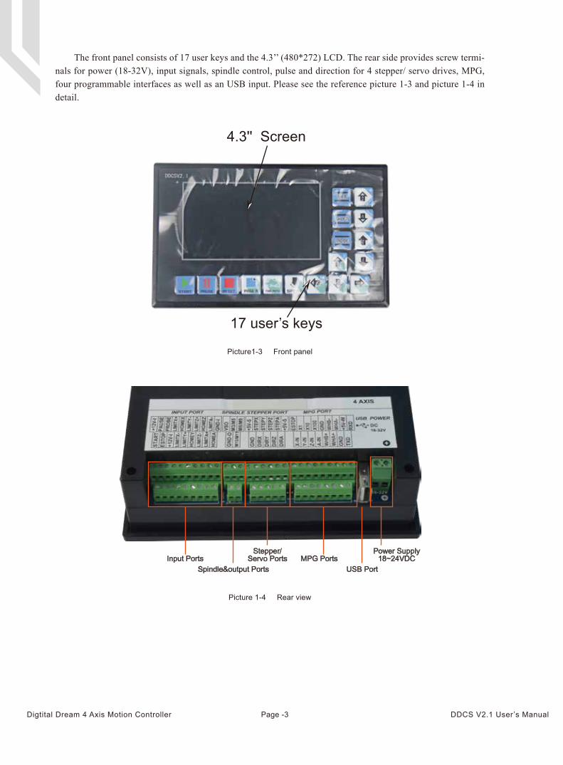
The front panel consists of 17 user keys and the 4.3’’ (480*272) LCD. The rear side provides screw termi-nals for power (18-32V), input signals, spindle control, pulse and direction for 4 stepper/ servo drives, MPG, four programmable interfaces as well as an USB input. Please see the reference picture 1-3 and picture 1-4 in detail.
Picture1-3 Front panel
Picture 1-4 Rear view
4.3'' Screen
17 user’s keys
Input PortsSpindle&output Ports
Stepper/Servo Ports MPG Ports
Power Supply18~24VDC
USB Port
Page -3Digtital Dream 4 Axis Motion Controller DDCS V2.1 User’s Manual
When operating the DDCS V2.1, the users will come across some English abbreviations. Here a list with explanations
FRO: Feed Rate Override
SRO: Spindle Rate Override
SRJ: Jog Speed Setting
F: Feed rate, unit is mm/min
S: Spindle Speed, unit rev/min.
X: The coordinate code of the X axis.
Y: The coordinate code of the Y axis.
Z: The coordinate code of the Z axis.
A: The coordinate code of the A axis
BUSY: The system is busy. You still can adjust FRO and SRO
READY: READY mode, any operation can be done
RESET: Reset mode, controller is in “OFF” mode, no operation can be performed
CONT: Continuous mode, each axis can be manually jogged with the arrow keys
Step :Manual Step Mode,each axis can be jogged in defined steps
MPG: MPG mode. Operate the machine with the MPG (Manual Pulse Generator)
AUTO: Run G code. Auto is showing when file is processing
Keep away from exposure to moisture or water. This product contains sophisticated electronics and must not get wet.
Wiring warning: the IO input terminal of this controller supports equipment with source power (such as Inductive Proximity Switch ). When using this kind of equipment, pay attention to the polarity. Avoid the +terminal to be connect with GND. This controllers has analog output for spindle control (0-10V). Please avoid this terminal to ever connect with GND as damage to the controller may occur.
Operation warning. Please observe all security measures when operating the machine. The ESTOP must be connected and properly labelled. In case of a problem, press the E-stop at once to avoid
damage to humans, animals and the equipment.
High voltage danger. The DDCS V2.1 is connected to18-32V DC. Obey and follow the electricity safety rules of your country when connecting this equipment.
1.4 Explanation of Abbreviations
1.5 Notes and Warnings
Page -4Digtital Dream 4 Axis Motion Controller DDCS V2.1 User’s Manual
2 Wiring
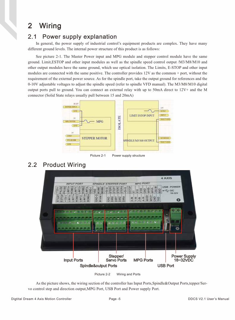
In general, the power supply of industrial control’s equipment products are complex. They have many different ground levels. The internal power structure of this product is as follows:
See picture 2-1. The Master Power input and MPG module and stepper control module have the same ground. Limit,ESTOP and other input modules as well as the spindle speed control output /M3/M8/M10 and other output modules have the same ground, which use optical isolation. The Limits, E-STOP and other input modules are connected with the same positive. The controller provides 12V as the common + port, without the requirement of the external power source. As for the spindle port, take the output ground for references and the 0-10V adjustable voltages to adjust the spindle speed (refer to spindle VFD manual). The M3/M8/M10 digital output ports pull to ground. You can connect an external relay with up to 50mA direct to 12V+ and the M connector (Solid State relays usually pull between 15 and 20mA)
As the picture shows, the wiring section of the controller has Input Ports,Spindle&Output Ports,tepper/Ser-vo control step and direction output,MPG Port, USB Port and Power supply Port.
2.1 Power supply explanation
2.2 Product Wiring
Picture 2-1 Power supply structure
Picture 2-2 Wiring and Ports
Input PortsSpindle&output Ports
Stepper/Servo Ports MPG Ports
Power Supply18~32VDC
USB Port
Page -5Digtital Dream 4 Axis Motion Controller DDCS V2.1 User’s Manual
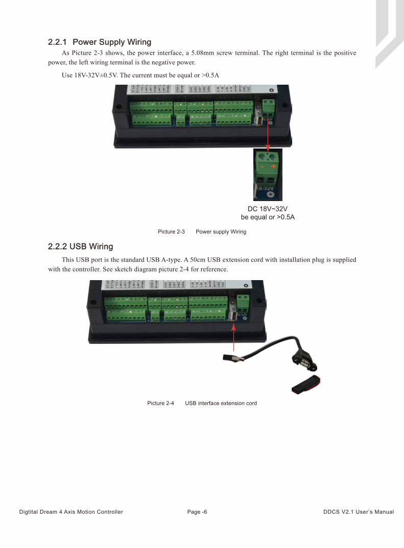
As Picture 2-3 shows, the power interface, a 5.08mm screw terminal. The right terminal is the positive power, the left wiring terminal is the negative power.
Use 18V-32V±0.5V. The current must be equal or >0.5A
2.2.1 Power Supply Wiring
This USB port is the standard USB A-type. A 50cm USB extension cord with installation plug is supplied with the controller. See sketch diagram picture 2-4 for reference.
2.2.2 USB Wiring
Picture 2-3 Power supply Wiring
Picture 2-4 USB interface extension cord
+-
DC 18V~32Vbe equal or >0.5A
Page -6Digtital Dream 4 Axis Motion Controller DDCS V2.1 User’s Manual
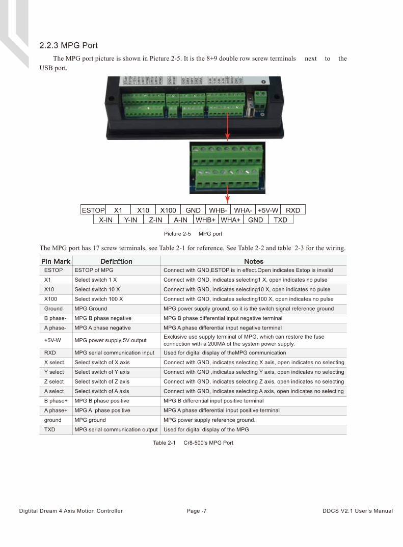
The MPG port picture is shown in Picture 2-5. It is the 8+9 double row screw terminals next to the USB port.
The MPG port has 17 screw terminals, see Table 2-1 for reference. See Table 2-2 and table 2-3 for the wiring.
2.2.3 MPG Port
Picture 2-5 MPG port
Table 2-1 Cr8-500’s MPG Port
Pin Mark Definition NotesESTOP of MPG Connect with GND,ESTOP is in effect.Open indicates Estop is invalid
Select switch 1 X Connect with GND, indicates selecting1 X, open indicates no pulse
Select switch 10 X Connect with GND, indicates selecting10 X, open indicates no pulse
Select switch 100 X Connect with GND, indicates selecting100 X, open indicates no pulse
MPG Ground MPG power supply ground, so it is the switch signal reference ground
MPG B phase negative MPG B phase differential input negative terminal
MPG A phase negative MPG A phase differential input negative terminal
MPG power supply 5V output Exclusive use supply terminal of MPG, which can restore the fuse connection with a 200MA of the system power supply.
MPG serial communication input Used for digital display of theMPG communication
Select switch of X axis Connect with GND, indicates selecting X axis, open indicates no selecting
Select switch of Y axis Connect with GND ,indicates selecting Y axis, open indicates no selecting
Select switch of Z axis Connect with GND, indicates selecting Z axis, open indicates no selecting
Select switch of A axis Connect with GND, indicates selecting A axis, open indicates no selecting
MPG B phase positive MPG B differential input positive terminal
MPG A phase positive MPG A phase differential input positive terminal
MPG ground MPG power supply reference ground.
MPG serial communication output Used for digital display of the MPG
ESTOP
X10
X100
Ground
B phase-
A phase-
+5V-W
RXD
X select
Y select
Z select
A select
B phase+
A phase+
ground
TXD
X1
ESTOP X1 X10 X100 GND WHB- WHA- +5V-W RXDX-IN Y-IN Z-IN A-IN WHB+ WHA+ GND TXD
Page -7Digtital Dream 4 Axis Motion Controller DDCS V2.1 User’s Manual
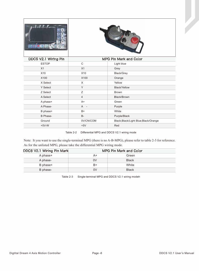
Note: It you want to use the single-terminal MPG (there is no A-B-MPG), please refer to table 2-3 for reference. As for the unlisted MPG, please take the differential MPG wiring mode.
DDCS V2.1 Wiring Pin MPG Pin Mark and ColorC
Light blue
X1 Grey
X10 Black/Grey
X100 Orange
X Yellow
Y Black/Yellow
Z Brown
4 Black/Brown/
A+ Green
A - Purple
B+
B-
White
Purple/Black
0V/CN/COM Black;Black/Light Blue;Black/Orange
Red
X1
X10
X100
X Select
Y Select
Z Select
A Select
A phase+
A Phase-
B phase+
B Phase-
Ground
+5V-W
ESTOP
+5V
Table 2-2 Differential MPG and DDCS V2.1 wiring mode
Table 2-3 Single-terminal MPG and DDCS V2.1 wiring modeh
A+ Green0V BlackB+ White0V Black
DDCS V2.1 Wiring Pin Mark MPG Pin Mark and Color
A phase+A phase-B phase+B phase-
Page -8Digtital Dream 4 Axis Motion Controller DDCS V2.1 User’s Manual
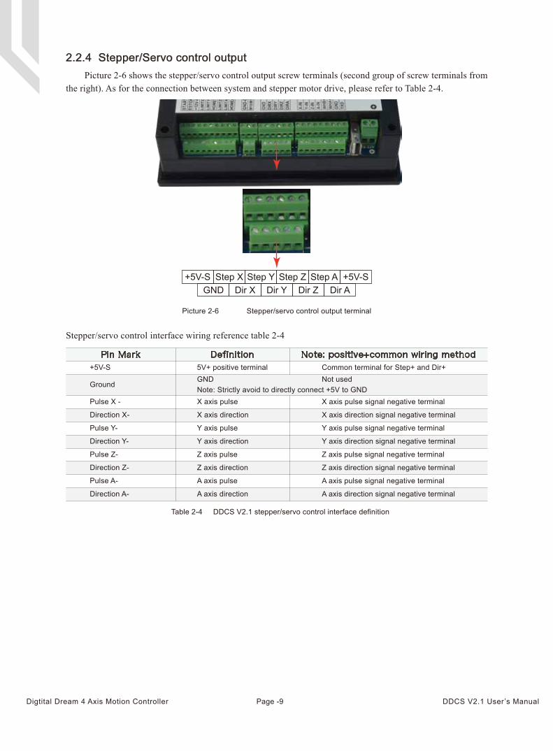
Picture 2-6 shows the stepper/servo control output screw terminals (second group of screw terminals from the right). As for the connection between system and stepper motor drive, please refer to Table 2-4.
2.2.4 Stepper/Servo control output
Picture 2-6 Stepper/servo control output terminal
GND Dir X Dir Y Dir Z Dir A+5V-S Step X Step Y Step Z Step A +5V-S
Stepper/servo control interface wiring reference table 2-4
Table 2-4 DDCS V2.1 stepper/servo control interface definition
Pin Mark Definition Note: positive+common wiring method
Note: Strictly avoid to directly connect +5V to GND
+5V-S
Ground
Pulse X -
Direction X-
Pulse Y-
Direction Y-
Pulse Z-
Direction Z-
Pulse A-
Direction A-
5V+ positive terminalGND
X axis pulse
X axis direction
Y axis pulse
Y axis direction
Z axis pulse
Z axis direction
A axis pulse
A axis direction
Common terminal for Step+ and Dir+Not used
X axis pulse signal negative terminal
X axis direction signal negative terminal
Y axis pulse signal negative terminal
Y axis direction signal negative terminal
Z axis pulse signal negative terminal
Z axis direction signal negative terminal
A axis pulse signal negative terminal
A axis direction signal negative terminal
Page -9Digtital Dream 4 Axis Motion Controller DDCS V2.1 User’s Manual
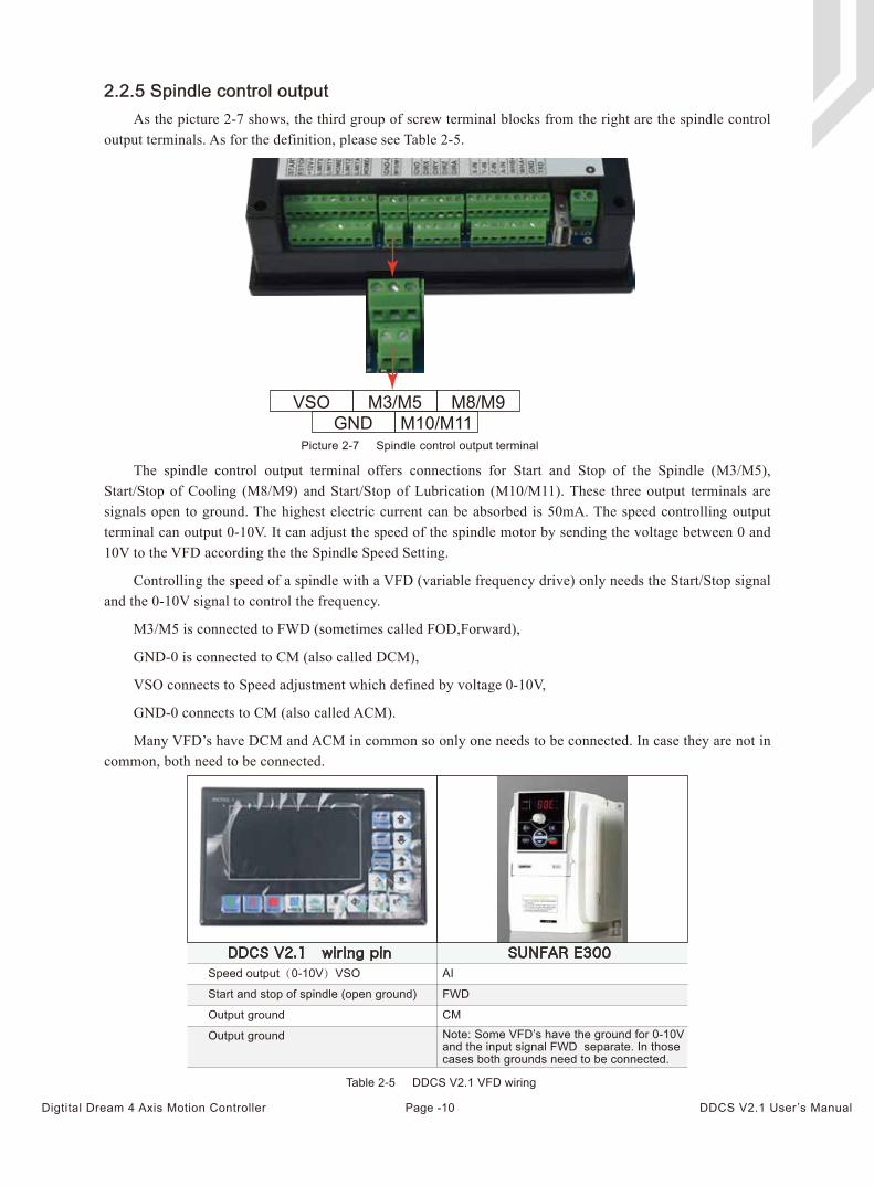
The spindle control output terminal offers connections for Start and Stop of the Spindle (M3/M5), Start/Stop of Cooling (M8/M9) and Start/Stop of Lubrication (M10/M11). These three output terminals are signals open to ground. The highest electric current can be absorbed is 50mA. The speed controlling output terminal can output 0-10V. It can adjust the speed of the spindle motor by sending the voltage between 0 and 10V to the VFD according the the Spindle Speed Setting.
Controlling the speed of a spindle with a VFD (variable frequency drive) only needs the Start/Stop signal and the 0-10V signal to control the frequency.
M3/M5 is connected to FWD (sometimes called FOD,Forward),
GND-0 is connected to CM (also called DCM),
VSO connects to Speed adjustment which defined by voltage 0-10V,
GND-0 connects to CM (also called ACM).
Many VFD’s have DCM and ACM in common so only one needs to be connected. In case they are not in common, both need to be connected.
As the picture 2-7 shows, the third group of screw terminal blocks from the right are the spindle control output terminals. As for the definition, please see Table 2-5.
2.2.5 Spindle control output
Picture 2-7 Spindle control output terminal
VSO M3/M5 M8/M9M10/M11GND
DDCS V2.1 wiring pin SUNFAR E300 AI
FWD
CM
Speed output(0-10V)VSO
Start and stop of spindle (open ground)
Output ground
Output ground Note: Some VFD’s have the ground for 0-10Vand the input signal FWD separate. In thosecases both grounds need to be connected.
Table 2-5 DDCS V2.1 VFD wiring
Page -10Digtital Dream 4 Axis Motion Controller DDCS V2.1 User’s Manual
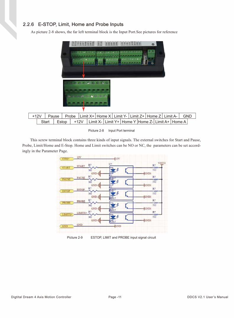
This screw terminal block contains three kinds of input signals. The external switches for Start and Pause, Probe, Limit/Home and E-Stop. Home and Limit switches can be NO or NC, the parameters can be set accord-ingly in the Parameter Page.
As picture 2-8 shows, the far left terminal block is the Input Port.See pictures for reference
2.2.6 E-STOP, Limit, Home and Probe Inputs
Picture 2-8 Input Port terminal
Start Estop +12V Limit X- Limit Y+ Home Y Home Z- Limit A+ Home A+12V Pause Probe Limit X+ Home X Limit Y- Limit Z+ Home Z Limit A- GND
Picture 2-9 ESTOP, LIMIT and PROBE input signal circuit
Page -11Digtital Dream 4 Axis Motion Controller DDCS V2.1 User’s Manual
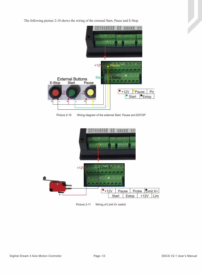
The following picture 2-10 shows the wiring of the external Start, Pause and E-Stop
Picture 2-10 Wiring diagram of the external Start, Pause and ESTOP
Picture 2-11 Wiring of Limit X+ switch
E-Stop Start PauseExternal Buttons
-+ -+ -+
Start Estop
Pause+12V
Start Estop +12V Limit X- Limit Y+ Home Y+12V Pause Probe Limit X+ Home X Limit Y-
+
-
+12V Limit X+
Start Estop +12V Limit X- Limit Y+ Home Y Home Z-+12V Pause Probe Limit X+ Home X Limit Y- Limit Z+
Page -12Digtital Dream 4 Axis Motion Controller DDCS V2.1 User’s Manual
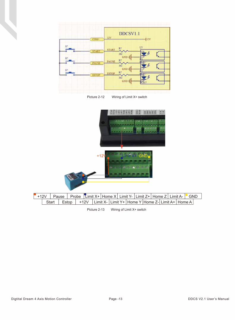
Picture 2-12 Wiring of Limit X+ switch
Picture 2-13 Wiring of Limit X+ switch
Home Z- Limit A+ Home ALimit Z+ Home Z Limit A- GND
Limit A+ Home ALimit A- GND
Start Estop +12V Limit X- Limit Y+ Home Y Home Z- Limit A+ Home A+12V Pause Probe Limit X+ Home X Limit Y- Limit Z+ Home Z Limit A- GND
+12V Limit X+ GND
Page -13Digtital Dream 4 Axis Motion Controller DDCS V2.1 User’s Manual
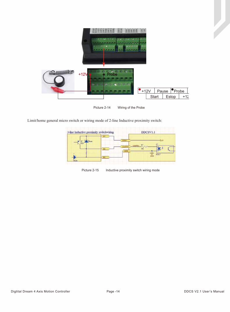
Picture 2-14 Wiring of the Probe
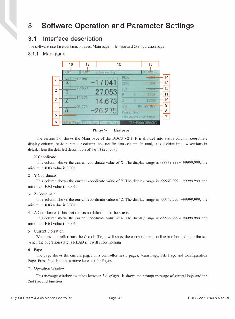
Limit/home general micro switch or wiring mode of 2-line Inductive proximity switch:
Picture 2-15 Inductive proximity switch wiring mode
+12V Probe
Start Estop +12V Limit X- Limit Y+ Home Y+12V Pause Probe Limit X+ Home X Limit Y-
Page -14Digtital Dream 4 Axis Motion Controller DDCS V2.1 User’s Manual
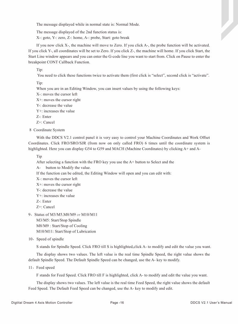
The picture 3-1 shows the Main page of the DDCS V2.1. It is divided into status column, coordinate display column, basic parameter column, and notification column. In total, it is divided into 18 sections in detail. Here the detailed description of the 18 sections :
1、X CoordinateThis column shows the current coordinate value of X. The display range is -99999.999~+99999.999, the
minimum JOG value is 0.001.
2、Y CoordinateThis column shows the current coordinate value of Y. The display range is -99999.999~+99999.999, the
minimum JOG value is 0.001.
3、Z CoordinateThis column shows the current coordinate value of Z. The display range is -99999.999~+99999.999, the
minimum JOG value is 0.001.
4、A Coordinate(This section has no definition in the 3-axis)This column shows the current coordinate value of A. The display range is -99999.999~+99999.999, the
minimum JOG value is 0.001.
5、Current OperationWhen the controller runs the G code file, it will show the current operation line number and coordinates.
When the operation state is READY, it will show nothing
6、Page The page shows the current page. This controller has 3 pages, Main Page, File Page and Configuration
Page. Press Page button to move between the Pages.
7、Operation Window
This message window switches between 3 displays. It shows the prompt message of several keys and the 2nd (second function)
3 Software Operation and Parameter Settings
3.1 Interface descriptionThe software interface contains 3 pages. Main page, File page and Configuration page.
Picture 3-1 Main page
3.1.1 Main page
1
7891011121314
18 17 16 15
2
3
4
5
6
Home Z- Limit A+ Home ALimit Z+ Home Z Limit A- GND
Page -15Digtital Dream 4 Axis Motion Controller DDCS V2.1 User’s Manual
The message displayed while in normal state is: Normal Mode.
The message displayed of the 2nd function status is: X-: goto, Y-: zero, Z-: home, A-: probe, Start: goto break
If you now click X-, the machine will move to Zero. If you click A-, the probe function will be activated. If you click Y-, all coordinates will be set to Zero. If you click Z-, the machine will home. If you click Start, the Start Line window appears and you can enter the G-code line you want to start from. Click on Pause to enter the breakpoint CONT Callback Function.
Tip: You need to click these functions twice to activate them (first click is “select”, second click is “activate”.
Tip:When you are in an Editing Window, you can insert values by using the following keys:X-: moves the cursor leftX+: moves the cursor rightY-: decrease the valueY+: increases the valueZ-: Enter Z+: Cancel
8 Coordinate System
With the DDCS V2.1 control panel it is very easy to control your Machine Coordinates and Work Offset Coordinates. Click FRO/SRO/SJR (from now on only called FRO) 6 times until the coordinate system is highlighted. Here you can display G54 to G59 and MACH (Machine Coordinates) by clicking A+ and A-
TipAfter selecting a function with the FRO key you use the A+ button to Select and the A- button to Modify the value. If the function can be edited, the Editing Window will open and you can edit with:X-: moves the cursor leftX+: moves the cursor rightY-: decrease the valueY+: increases the valueZ-: Enter Z+: Cancel
9、Status of M3/M5,M8/M9 or M10/M11M3/M5: Start/Stop SpindleM8/M9 : Start/Stop of CoolingM10/M11: Start/Stop of Lubrication
10、Speed of spindle
S stands for Spindle Speed. Click FRO till S is highlighted,click A- to modify and edit the value you want.
The display shows two values. The left value is the real time Spindle Speed, the right value shows the default Spindle Speed. The Default Spindle Speed can be changed, use the A- key to modify.
11、Feed speed
F stands for Feed Speed. Click FRO till F is highlighted, click A- to modify and edit the value you want.
The display shows two values. The left value is the real time Feed Speed, the right value shows the default Feed Speed. The Default Feed Speed can be changed, use the A- key to modify and edit.
Page -16Digtital Dream 4 Axis Motion Controller DDCS V2.1 User’s Manual
12、SJR
SJR controls the jogging of the machine. Click FRO till SJR is highlighted.
First Option: MODE
Check window 18 and you can see what Jog Mode you are in. By clicking MODE you can change Jogging to Continuous, Step or to MPG, Window 18 will display this function.
When in Cont Mode, A+ and A- can adjust the speed in 10% increments
When in Step Mode, A+ and A- can change from 0.01mm to 0.1mm to 1mm and to 10mm
When in MPG mode you can use the MPG to jog the machine
Second Option: Jog a defined distance
13、SRO
SRO controls the Spindle Speed. Click FRO till SRO is highlighted, use A+ and A_to adjust the Spindle Speed in 10% increments
14、FRO
FRO controls the Feed Speed. Click FRO till FRO is highlighted. Use A+ and A- to adjust the Feed Speed in 10% increments
15、Working time
This column shows the processing time of the G code operation. Time keeping is halted during Pause
16、Processing file
This column shows the name of the processing files. In the formal situation, it only shows the filename. Under the situation of CONT adjust, it will also show the content of the file.
17、Operating Status
This column shows the operating state. The status and implications can be displayed as follows:
Busy: Operation is running
Reset: Reset flashing = controller not active. To activate the controller click Reset
READY: Ready state. Controller is ready and all operations can be performed
18、Feed status
This window shows the feed status of Jogging and File Processing.
AUTO: displayed while processing and executing the G code file
CONT: indicates Jog CONTINUOUS. You can Jog manually with the “-”or “+” keys of X Y Z and A. A short click will move the axis in the defined step, a long click will move the axis till you let go
Step: Jogging in Step Mode
Page -17Digtital Dream 4 Axis Motion Controller DDCS V2.1 User’s Manual
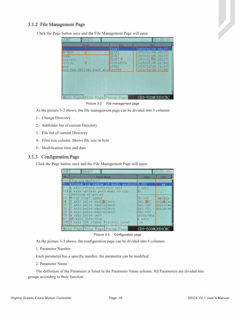
Click the Page button once and the File Management Page will open
As the picture 3-2 shows, the file management page can be divided into 5 columns
1、Change Directory
2、Subfolder list of current Directory
3、File list of current Directory
4、Files size column Shows file size in byte
5、Modification time and date
As the picture 3-3 shows, the configuration page can be divided into 4 columns:
1. Parameter Number
Each parameter has a specific number, the parameter can be modified .
2. Parameter Name
The definition of the Parameter is listed in the Parameter Name column. All Parameters are divided into groups according to their function.
Click the Page button once and the File Management Page will open:
Picture 3-2 File management page
3.1.3 Configuration Page
Picture 3-3 Configuration page
3.1.2 File Management Page
12
34 5
Page -18Digtital Dream 4 Axis Motion Controller DDCS V2.1 User’s Manual
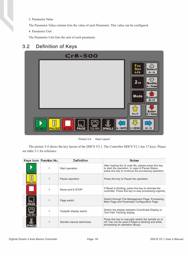
The picture 3-4 shows the key layout of the DDCS V2.1. The Controller DDCS V2.1 has 17 keys. Please see table 3-1 for reference.
Picture 3-4 Keys Layout
3.2 Definition of Keys
Keys Icon Function No. Definition Notes
3. Parameter Value
The Parameter Value column lists the value of each Parameter. This value can be configured
4. Parameter Unit
The Parameter Unit lists the unit of each parameter.
1
1
Start operationAfter loading the G code file, please press this keyto start the operation. In case of Pause Status,press this key to continue the processing operation.
Pause operation Press this key to Pause the operation.
1 Reset and E-STOP If Reset is blinking, press this key to activate thecontroller. Press this key to stop processing urgently.
1 Page switch
Toolpath display switch
Switch through File Management Page, ProcessingMain Page and Parameter Configuration Page.
1 Switch the display between Coordinate Display orTool Path Tracking display.
1 Spindle manual start/closePress this key to manually switch the spindle on oroff. Can not be used if Reset is blinking and whileprocessing an operation (Busy)
Page -19Digtital Dream 4 Axis Motion Controller DDCS V2.1 User’s Manual
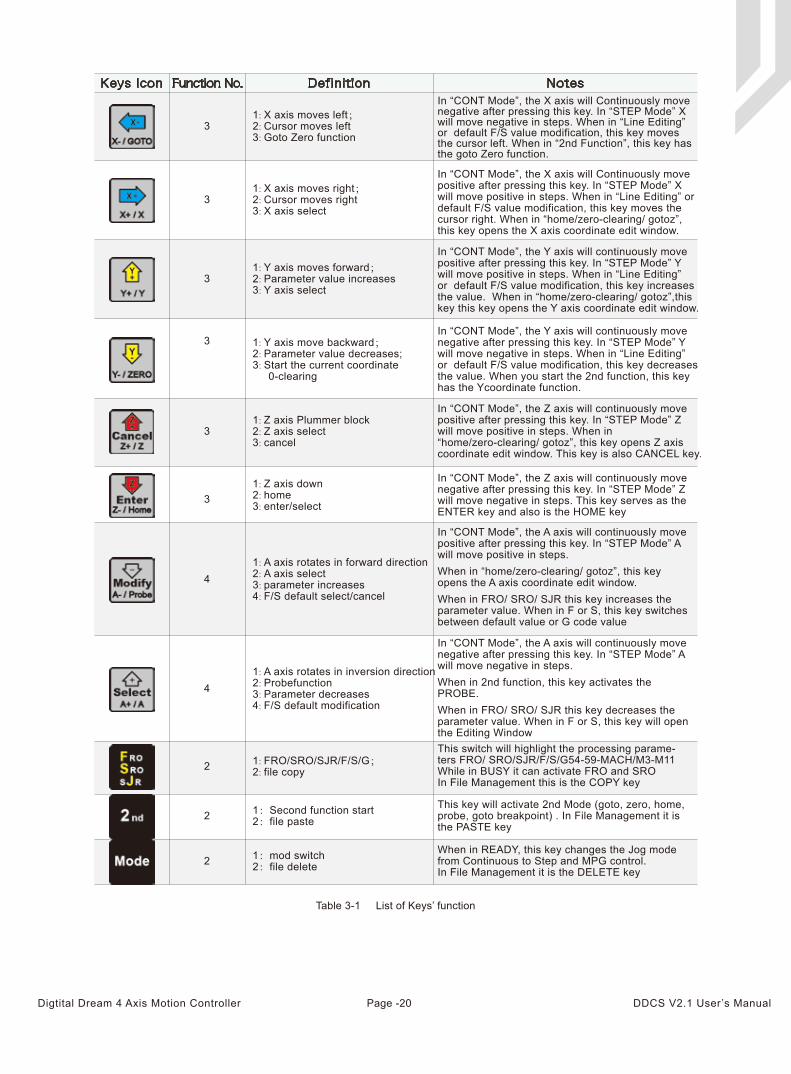
31: X axis moves left;2: Cursor moves left3: Goto Zero function
In “CONT Mode”, the X axis will Continuously movenegative after pressing this key. In “STEP Mode” Xwill move negative in steps. When in “Line Editing”or default F/S value modification, this key movesthe cursor left. When in “2nd Function”, this key hasthe goto Zero function.
31: X axis moves right;2: Cursor moves right3: X axis select
In “CONT Mode”, the X axis will Continuously movepositive after pressing this key. In “STEP Mode” Xwill move positive in steps. When in “Line Editing” or default F/S value modification, this key moves thecursor right. When in “home/zero-clearing/ gotoz”,this key opens the X axis coordinate edit window.
31: Y axis moves forward;2: Parameter value increases3: Y axis select
In “CONT Mode”, the Y axis will continuously movepositive after pressing this key. In “STEP Mode” Ywill move positive in steps. When in “Line Editing”or default F/S value modification, this key increasesthe value. When in “home/zero-clearing/ gotoz”,thiskey this key opens the Y axis coordinate edit window.
3
3
3
1: Y axis move backward;2: Parameter value decreases;3: Start the current coordinate 0-clearing
1: Z axis Plummer block2: Z axis select3: cancel
In “CONT Mode”, the Y axis will continuously movenegative after pressing this key. In “STEP Mode” Ywill move negative in steps. When in “Line Editing”or default F/S value modification, this key decreasesthe value. When you start the 2nd function, this keyhas the Ycoordinate function.
In “CONT Mode”, the Z axis will continuously movepositive after pressing this key. In “STEP Mode” Zwill move positive in steps. When in “home/zero-clearing/ gotoz”, this key opens Z axiscoordinate edit window. This key is also CANCEL key.
1: Z axis down2: home3: enter/select
In “CONT Mode”, the Z axis will continuously movenegative after pressing this key. In “STEP Mode” Zwill move negative in steps. This key serves as theENTER key and also is the HOME key
41: A axis rotates in forward direction2: A axis select3: parameter increases4: F/S default select/cancel
41: A axis rotates in inversion direction2: Probefunction3: Parameter decreases4: F/S default modification
2 1: FRO/SRO/SJR/F/S/G;2: file copy
2 1:Second function start2:file paste
2 1:mod switch2:file delete
Table 3-1 List of Keys’ function
Keys Icon Function No. Definition Notes
In “CONT Mode”, the A axis will continuously move positive after pressing this key. In “STEP Mode” A will move positive in steps. When in “home/zero-clearing/ gotoz”, this key opens the A axis coordinate edit window. When in FRO/ SRO/ SJR this key increases the parameter value. When in F or S, this key switches between default value or G code value
In “CONT Mode”, the A axis will continuously move negative after pressing this key. In “STEP Mode” A will move negative in steps. When in 2nd function, this key activates the PROBE.When in FRO/ SRO/ SJR this key decreases the parameter value. When in F or S, this key will open the Editing WindowThis switch will highlight the processing parame-ters FRO/ SRO/SJR/F/S/G54-59-MACH/M3-M11 While in BUSY it can activate FRO and SRO In File Management this is the COPY key
This key will activate 2nd Mode (goto, zero, home, probe, goto breakpoint) . In File Management it is the PASTE key
When in READY, this key changes the Jog mode from Continuous to Step and MPG control.In File Management it is the DELETE key
Page -20Digtital Dream 4 Axis Motion Controller DDCS V2.1 User’s Manual
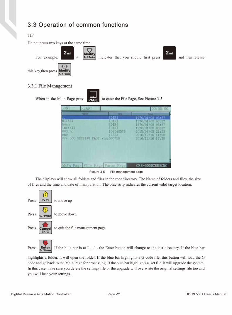
The displays will show all folders and files in the root directory. The Name of folders and files, the size of files and the time and date of manipulation. The blue strip indicates the current valid target location.
3.3 Operation of common functions
3.3.1 File Management
Picture 3-5 File management page
For example: + indicates that you should first press and then release
this key,then press
When in the Main Page press to enter the File Page, See Picture 3-5
Press If the blue bar is at “ . .” , the Enter button will change to the last directory. If the blue bar
highlights a folder, it will open the folder. If the blue bar highlights a G code file, this button will load the G code and go back to the Main Page for processing. If the blue bar highlights a .set file, it will upgrade the system. In this case make sure you delete the settings file or the upgrade will overwrite the original settings file too and you will lose your settings.
Press to move up
Press to move down
Press to quit the file management page
TIP
Do not press two keys at the same time
Page -21Digtital Dream 4 Axis Motion Controller DDCS V2.1 User’s Manual
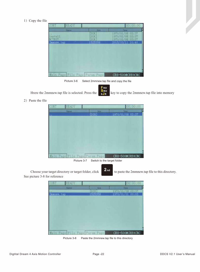
Picture 3-8 Paste the 2mmnew.tap file to this directory
Hrere the 2mmnew.tap file is selected. Press the key to copy the 2mmnew.tap file into memory
Choose your target directory or target folder, click to paste the 2mmnew.tap file to this directory. See picture 3-8 for reference
1)Copy the file
Picture 3-6 Select 2mmnew.tap file and copy the file
2)Paste the file
Picture 3-7 Switch to the target folder
Page -22Digtital Dream 4 Axis Motion Controller DDCS V2.1 User’s Manual
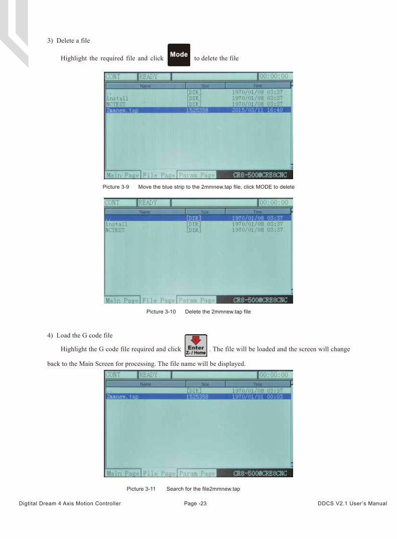
Highlight the required file and click to delete the file
Picture 3-9 Move the blue strip to the 2mmnew.tap file, click MODE to delete
Picture 3-10 Delete the 2mmnew.tap file
4) Load the G code file
Picture 3-11 Search for the file2mmnew.tap
Highlight the G code file required and click . The file will be loaded and the screen will change
back to the Main Screen for processing. The file name will be displayed.
3) Delete a file
Page -23Digtital Dream 4 Axis Motion Controller DDCS V2.1 User’s Manual
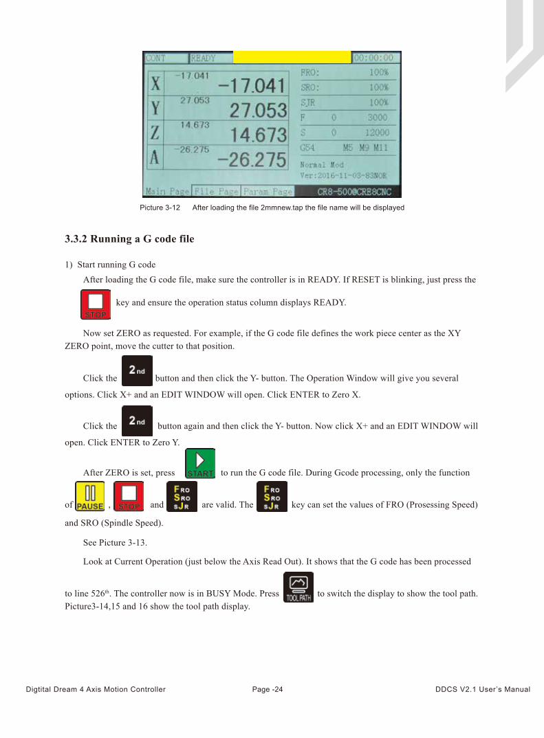
After loading the G code file, make sure the controller is in READY. If RESET is blinking, just press the
key and ensure the operation status column displays READY.
See Picture 3-13.
Now set ZERO as requested. For example, if the G code file defines the work piece center as the XY ZERO point, move the cutter to that position.
Picture 3-12 After loading the file 2mmnew.tap the file name will be displayed
3.3.2 Running a G code file
1) Start running G code
Click the button again and then click the Y- button. Now click X+ and an EDIT WINDOW will
open. Click ENTER to Zero Y.
Click the button and then click the Y- button. The Operation Window will give you several
options. Click X+ and an EDIT WINDOW will open. Click ENTER to Zero X.
After ZERO is set, press to run the G code file. During Gcode processing, only the function
of , and and are valid. The key can set the values of FRO (Prosessing Speed)
and SRO (Spindle Speed).
Look at Current Operation (just below the Axis Read Out). It shows that the G code has been processed
to line 526th. The controller now is in BUSY Mode. Press to switch the display to show the tool path. Picture3-14,15 and 16 show the tool path display.
Page -24Digtital Dream 4 Axis Motion Controller DDCS V2.1 User’s Manual
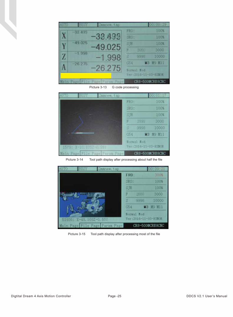
Picture 3-13 G code processing
Picture 3-14 Tool path display after processing about half the file
Picture 3-15 Tool path display after processing most of the file
Page -25Digtital Dream 4 Axis Motion Controller DDCS V2.1 User’s Manual
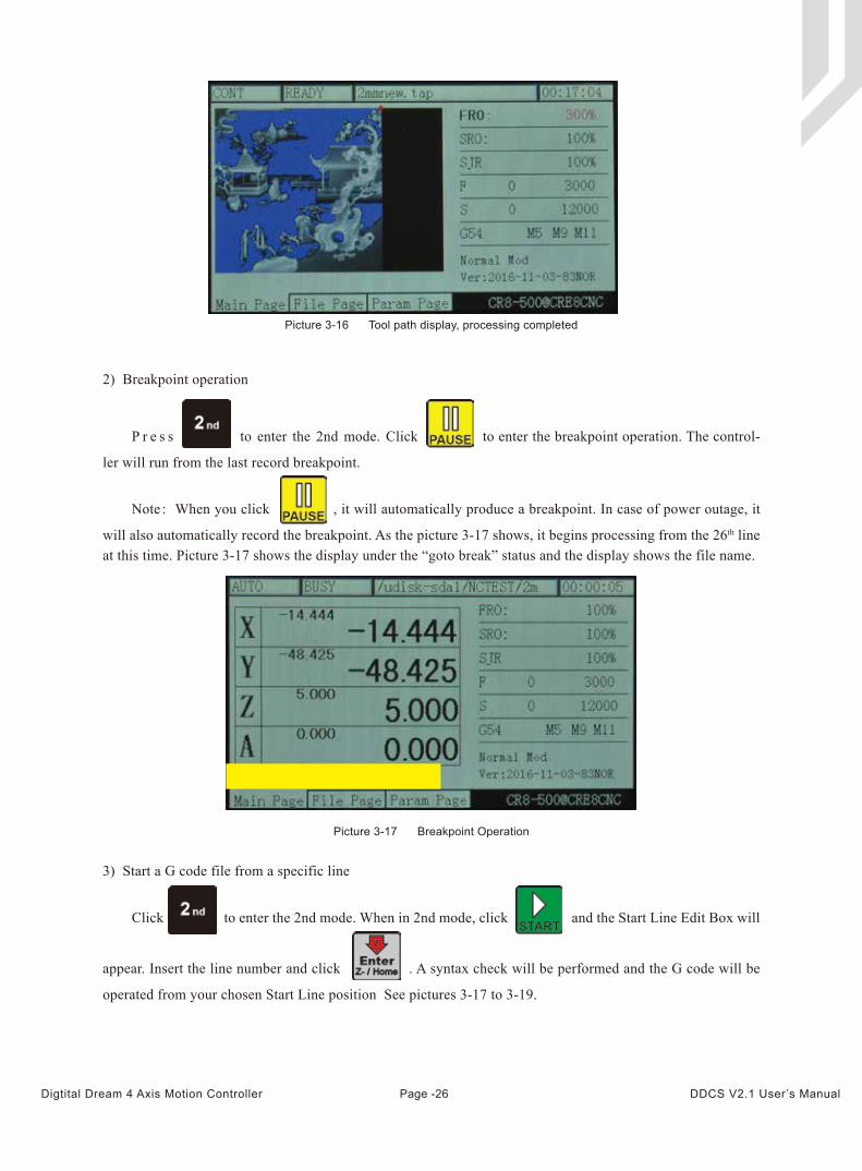
Picture 3-16 Tool path display, processing completed
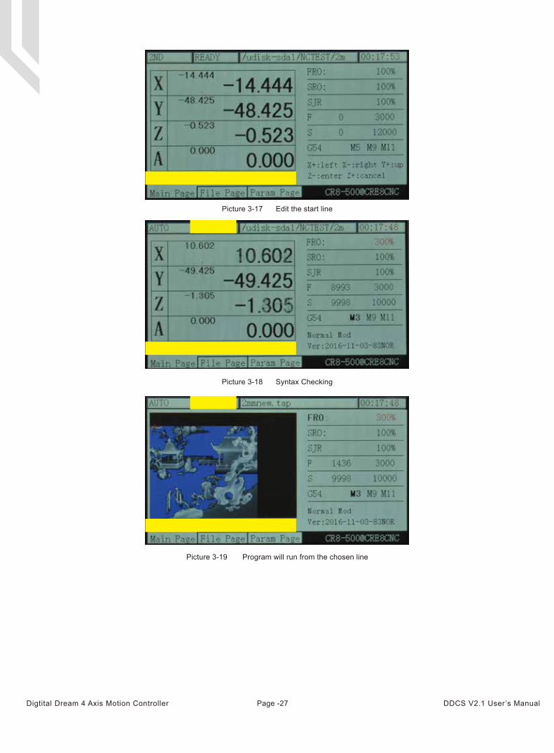
Picture 3-17 Breakpoint Operation
2) Breakpoint operation
3) Start a G code file from a specific line
Note:When you click , it will automatically produce a breakpoint. In case of power outage, it
will also automatically record the breakpoint. As the picture 3-17 shows, it begins processing from the 26th line at this time. Picture 3-17 shows the display under the “goto break” status and the display shows the file name.
P r e s s to enter the 2nd mode. Click to enter the breakpoint operation. The control-
ler will run from the last record breakpoint.
Click to enter the 2nd mode. When in 2nd mode, click and the Start Line Edit Box will
appear. Insert the line number and click . A syntax check will be performed and the G code will be
operated from your chosen Start Line position See pictures 3-17 to 3-19.
Page -26Digtital Dream 4 Axis Motion Controller DDCS V2.1 User’s Manual
Picture 3-17 Edit the start line
Picture 3-18 Syntax Checking
Picture 3-19 Program will run from the chosen line
Page -27Digtital Dream 4 Axis Motion Controller DDCS V2.1 User’s Manual
You can manually position the machine at any position. You can move Continuous, in defined Steps or with
the MPG. The button moves you through the three options
3.3.3 Manually position the machine
1) Manual step of the X axis
Press till “step” is displayed. In picture 3-22 Step parameter shows the current step rate (10mm).
Press the button till SJR is highlighted and you can change the steps by and keys.
Press the key to move the X axis negative 1mm,and press to move the X axis 1mm positive.
Move Y Z and A in the same way.
During file processing, press the key to ESTOP the procedure. The Operation Status
Column will display “RESET” flashing. The spindle will stop.
Only when the Operation Status Column displays “READY” you can manually start or stop the spindle.
Use the spindle button to switch from Start to Stop and back.
5) ESTOP in operation
6) Start/Stop spindle
During file processing, press the key to pause the operation. The Operation Status Column will
display “READY” and the Z axis will lift the tool to the defined safe height.
4) Pause in operation
Cli c k t i l l C O N T i s d i s p l a y e d . T h e f e e d s t a t u s d i s p l a y s “ C O N T ” . S e e p i c t u r e
3 - 2 2 . Yo u c a n n o w m o v e t h e a x i s c o n t i n u o u s w i t h t h e a r r o w k e y s . A d j u s t t h e J o g s p e e d
b y h i g h l i g h t i n g S J R a n d m o d i f y t h e j o g s p e e d w i t h a n d . A l l o t h e r a x e s
c a n be moved in the same way.
2) Manual continuous operation of the X axis
Page -28Digtital Dream 4 Axis Motion Controller DDCS V2.1 User’s Manual
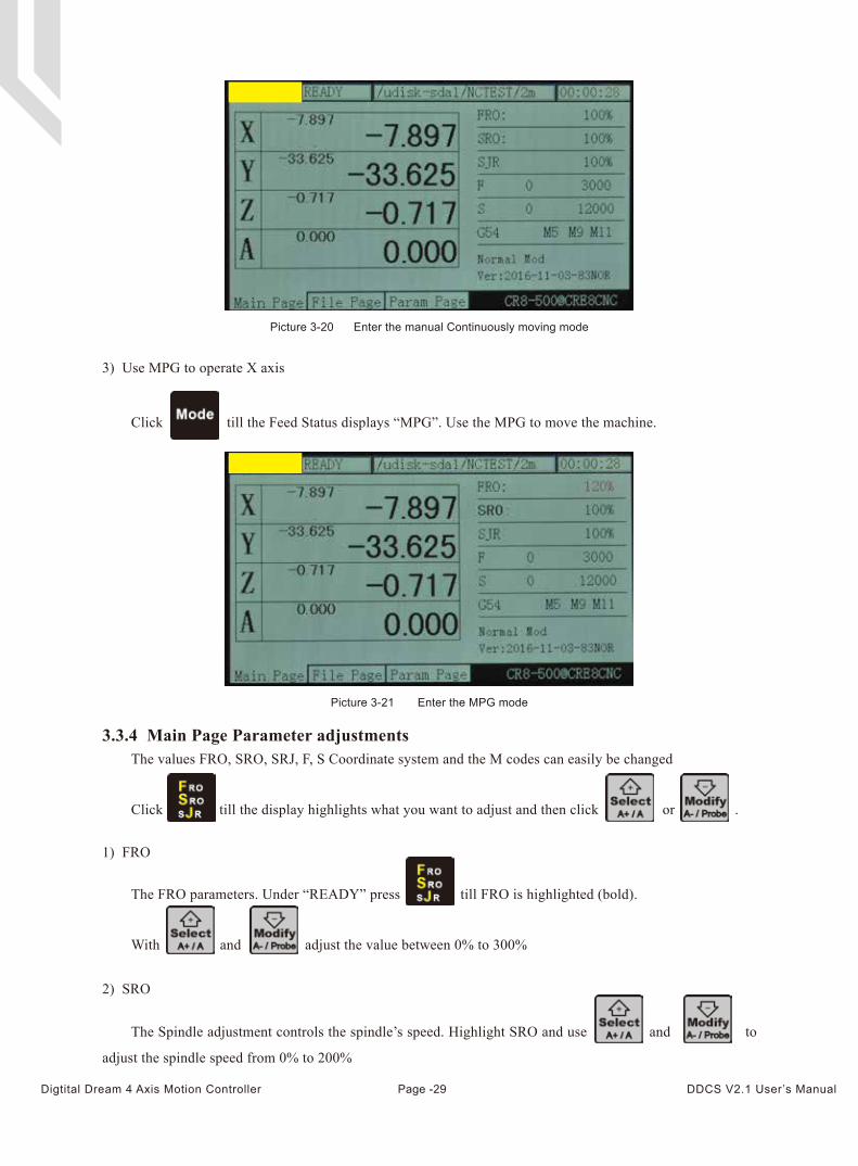
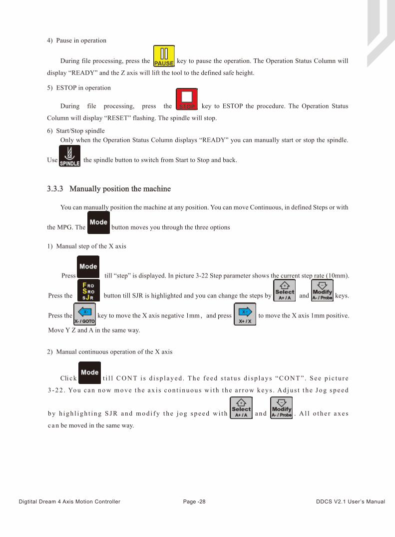
Picture 3-20 Enter the manual Continuously moving mode
3) Use MPG to operate X axis
Picture 3-21 Enter the MPG mode
3.3.4 Main Page Parameter adjustmentsThe values FRO, SRO, SRJ, F, S Coordinate system and the M codes can easily be changed
Click till the display highlights what you want to adjust and then click or .
Click till the Feed Status displays “MPG”. Use the MPG to move the machine.
The FRO parameters. Under “READY” press till FRO is highlighted (bold).
With and adjust the value between 0% to 300%
The Spindle adjustment controls the spindle’s speed. Highlight SRO and use and to
adjust the spindle speed from 0% to 200%
1) FRO
2) SRO
Page -29Digtital Dream 4 Axis Motion Controller DDCS V2.1 User’s Manual
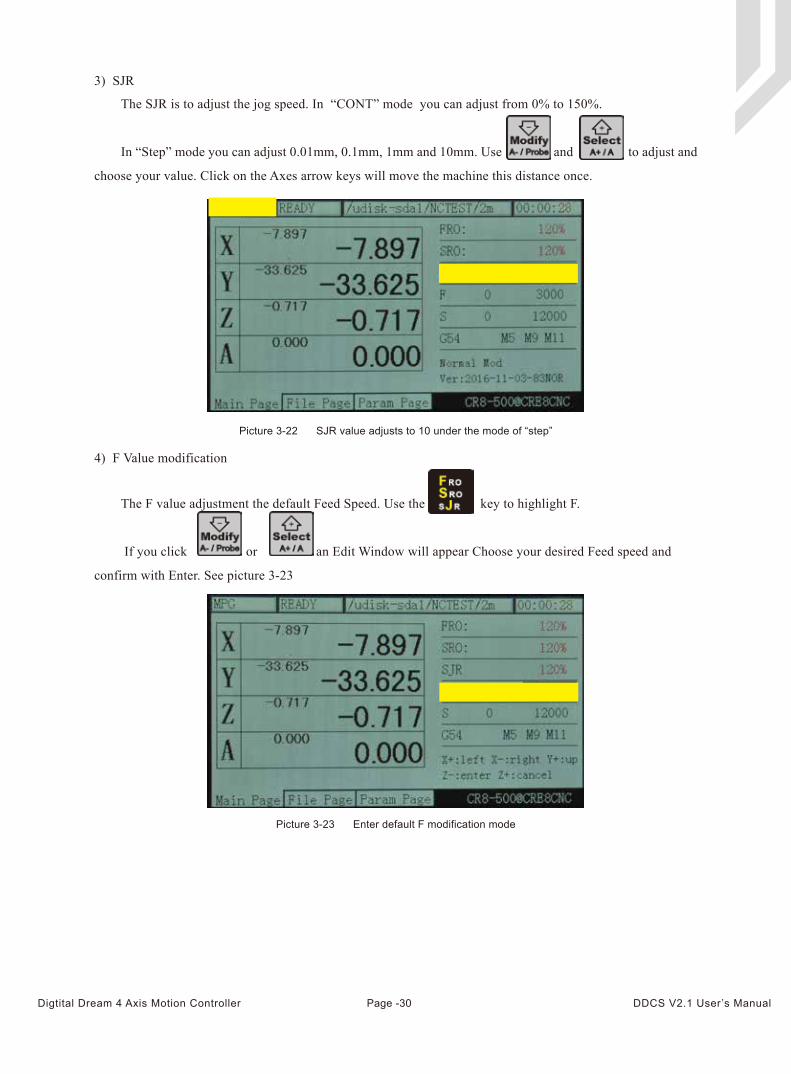
Picture 3-22 SJR value adjusts to 10 under the mode of “step”
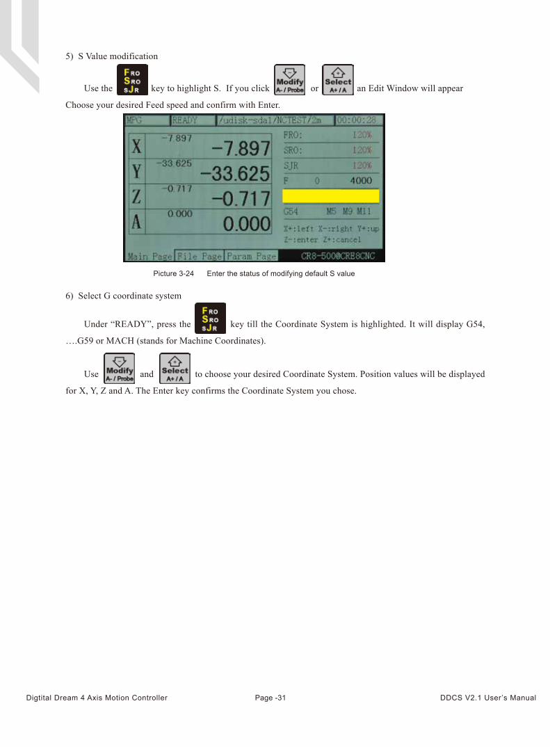
Picture 3-23 Enter default F modification mode
The SJR is to adjust the jog speed. In “CONT” mode you can adjust from 0% to 150%.
In “Step” mode you can adjust 0.01mm, 0.1mm, 1mm and 10mm. Use and to adjust and
choose your value. Click on the Axes arrow keys will move the machine this distance once.
3) SJR
4) F Value modification
The F value adjustment the default Feed Speed. Use the key to highlight F.
If you click or an Edit Window will appear Choose your desired Feed speed and
confirm with Enter. See picture 3-23
Page -30Digtital Dream 4 Axis Motion Controller DDCS V2.1 User’s Manual
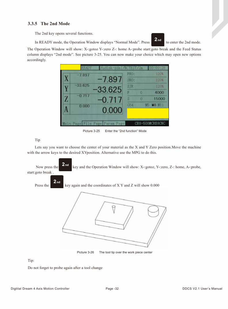
5) S Value modification
Picture 3-24 Enter the status of modifying default S value
6) Select G coordinate system
Under “READY”, press the key till the Coordinate System is highlighted. It will display G54,
….G59 or MACH (stands for Machine Coordinates).
Use and to choose your desired Coordinate System. Position values will be displayed
for X, Y, Z and A. The Enter key confirms the Coordinate System you chose.
Use the key to highlight S. If you click or an Edit Window will appear
Choose your desired Feed speed and confirm with Enter.
Page -31Digtital Dream 4 Axis Motion Controller DDCS V2.1 User’s Manual
Tip
Lets say you want to choose the center of your material as the X and Y Zero position.Move the machine with the arrow keys to the desired XYposition. Alternative use the MPG to do this.
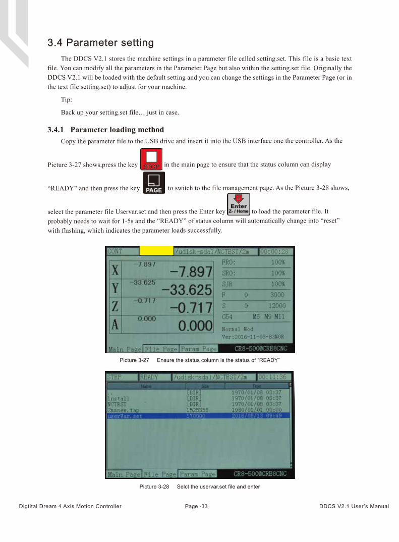
3.3.5 The 2nd Mode
Picture 3-25 Enter the “2nd function” Mode
Picture 3-26 The tool tip over the work piece center
Tip:
Do not forget to probe again after a tool change
Now press the key and the Operation Window will show: X-:gotoz, Y-:zero, Z-: home, A-:probe, start:goto break .
Press the key again and the coordinates of X Y and Z will show 0.000
The 2nd key opens several functions.
In READY mode, the Operation Window displays “Normal Mode”. Press to enter the 2nd mode.
The Operation Window will show: X-:gotoz Y-:zero Z-: home A-:probe start:goto break and the Feed Status column displays “2nd mode”. See picture 3-25. You can now make your choice which may open new options accordingly.
Page -32Digtital Dream 4 Axis Motion Controller DDCS V2.1 User’s Manual
Picture 3-28 Selct the uservar.set file and enter
The DDCS V2.1 stores the machine settings in a parameter file called setting.set. This file is a basic text file. You can modify all the parameters in the Parameter Page but also within the setting.set file. Originally the DDCS V2.1 will be loaded with the default setting and you can change the settings in the Parameter Page (or in the text file setting.set) to adjust for your machine.
Tip:
Back up your setting.set file… just in case.
Copy the parameter file to the USB drive and insert it into the USB interface one the controller. As the
Picture 3-27 shows,press the key in the main page to ensure that the status column can display
“READY” and then press the key to switch to the file management page. As the Picture 3-28 shows,
select the parameter file Uservar.set and then press the Enter key to load the parameter file. It probably needs to wait for 1-5s and the “READY” of status column will automatically change into “reset” with flashing, which indicates the parameter loads successfully.
3.4 Parameter setting
3.4.1 Parameter loading method
Picture 3-27 Ensure the status column is the status of “READY”
Page -33Digtital Dream 4 Axis Motion Controller DDCS V2.1 User’s Manual
The parameter file can be edited, but it needs to follow the definite standards, the standards are as follows:
a、One line can only be edited one parameter.
b、The parameter format is #parameter mark= value. Among them, # must be the first character of each line.# should closely be followed by the parameter mar and the following mark is=, and the make= will be followed by the actual value.
c、After the parameter has assignment and equation, the part of parameter interpretation can have any format without constraint.
d、Each parameter is regulated with assignment scope. Please do the assignment in strict accordance with the assignment scope.
e、Each parameter is set with default value in advance. Please use the setting value of default parameter under the situation of not understanding the actual function of this parameter.
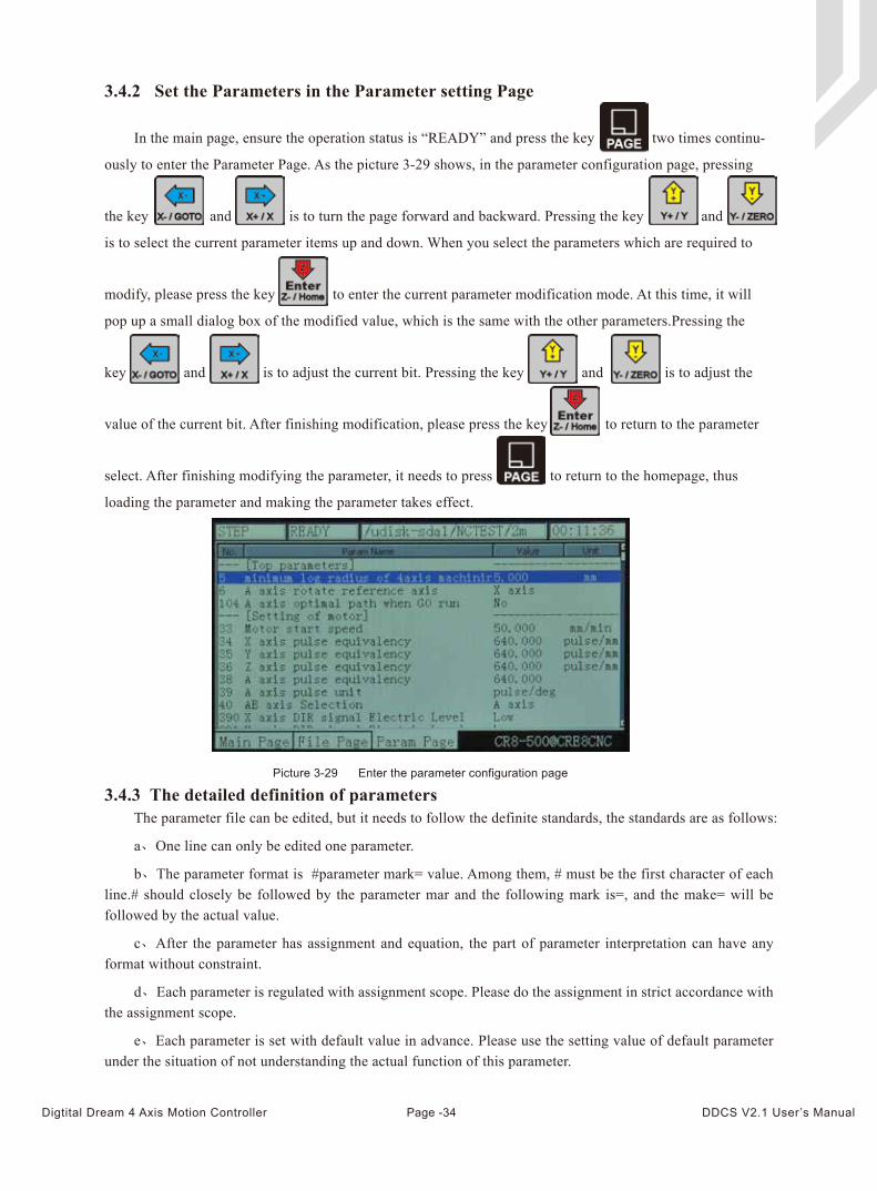
3.4.2 Set the Parameters in the Parameter setting Page
Picture 3-29 Enter the parameter configuration page
3.4.3 The detailed definition of parameters
In the main page, ensure the operation status is “READY” and press the key two times continu-
ously to enter the Parameter Page. As the picture 3-29 shows, in the parameter configuration page, pressing
the key and is to turn the page forward and backward. Pressing the key and
is to select the current parameter items up and down. When you select the parameters which are required to
modify, please press the key to enter the current parameter modification mode. At this time, it will
pop up a small dialog box of the modified value, which is the same with the other parameters.Pressing the
key and is to adjust the current bit. Pressing the key and is to adjust the
value of the current bit. After finishing modification, please press the key to return to the parameter
select. After finishing modifying the parameter, it needs to press to return to the homepage, thus
loading the parameter and making the parameter takes effect.
Page -34Digtital Dream 4 Axis Motion Controller DDCS V2.1 User’s Manual
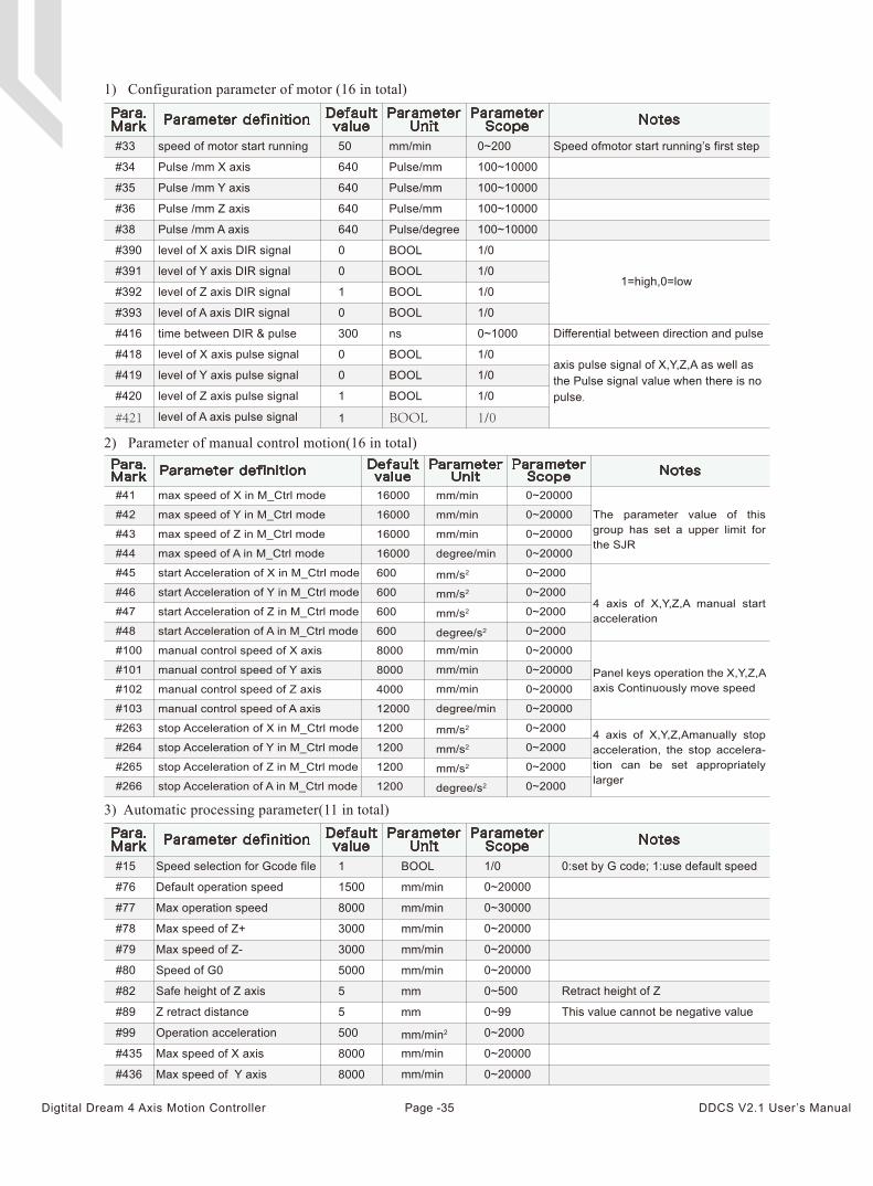
1) Configuration parameter of motor (16 in total)
3) Automatic processing parameter(11 in total)
Para.Mark Parameter definition Default
valueParameterUnit
ParameterScope Notes
Speed ofmotor start running’s first step
1=high,0=low
Differential between direction and pulse
50
640
640
640
640
0
0
1
0
300
0
0
1
1
mm/min
Pulse/mm
Pulse/mm
Pulse/mm
Pulse/degree
BOOL
BOOL
BOOL
BOOL
ns
BOOL
BOOL
BOOL
BOOL
0~200
100~10000
100~10000
100~10000
100~10000
1/0
1/0
1/0
1/0
0~1000
1/0
1/0
1/0
1/0
#33
#34
#35
#36
#38
#390
#391
#392
#393
#416
#418
#419
#420
#421
speed of motor start running
Pulse /mm X axis
Pulse /mm Y axis
Pulse /mm Z axis
Pulse /mm A axis
level of X axis DIR signal
level of Y axis DIR signal
level of Z axis DIR signal
level of A axis DIR signal
time between DIR & pulse
level of X axis pulse signal
level of Y axis pulse signal
level of Z axis pulse signal
level of A axis pulse signal
axis pulse signal of X,Y,Z,A as well as the Pulse signal value when there is no pulse.
2) Parameter of manual control motion(16 in total)
#41
#42
#43
#44
#45
#46
#47
#48
#100
#101
#102
#103
#263
#264
#265
#266
0~20000
0~20000
0~20000
0~20000
0~2000
0~2000
0~2000
0~2000
0~20000
0~20000
0~20000
0~20000
0~2000
0~2000
0~2000
0~2000
max speed of X in M_Ctrl mode
max speed of Y in M_Ctrl mode
max speed of Z in M_Ctrl mode
max speed of A in M_Ctrl mode
start Acceleration of X in M_Ctrl mode
start Acceleration of Y in M_Ctrl mode
start Acceleration of Z in M_Ctrl mode
start Acceleration of A in M_Ctrl mode
manual control speed of X axis
manual control speed of Y axis
manual control speed of Z axis
manual control speed of A axis
stop Acceleration of X in M_Ctrl mode
stop Acceleration of Y in M_Ctrl mode
stop Acceleration of Z in M_Ctrl mode
stop Acceleration of A in M_Ctrl mode
16000
16000
16000
16000
600
600
600
600
8000
8000
4000
12000
1200
1200
1200
1200
mm/min
mm/min
mm/min
degree/min
mm/s2
mm/s2
mm/s2
degree/s2
mm/min
mm/min
mm/min
degree/min
mm/s2
mm/s2
mm/s2
degree/s2
Para.Mark Parameter definition Default
valueParameterUnit
ParameterScope Notes
The parameter value of this group has set a upper limit for the SJR
4 axis of X,Y,Z,A manual start acceleration
Panel keys operation the X,Y,Z,A axis Continuously move speed
4 axis of X,Y,Z,Amanually stop acceleration, the stop accelera-tion can be set appropriately larger
0:set by G code; 1:use default speed
Retract height of Z
This value cannot be negative value
#15
#76
#77
#78
#79
#80
#82
#89
#99
#435
#436
Speed selection for Gcode file
Default operation speed
Max operation speed
Max speed of Z+
Max speed of Z-
Speed of G0
Safe height of Z axis
Z retract distance
Operation acceleration
Max speed of X axis
Max speed of Y axis
1
1500
8000
3000
3000
5000
5
5
500
8000
8000
BOOL
mm/min
mm/min
mm/min
mm/min
mm/min
mm
mm
mm/min2
mm/min
mm/min
1/0
0~20000
0~30000
0~20000
0~20000
0~20000
0~500
0~99
0~2000
0~20000
0~20000
Para.Mark Parameter definition Default
valueParameterUnit
ParameterScope Notes
Page -35Digtital Dream 4 Axis Motion Controller DDCS V2.1 User’s Manual
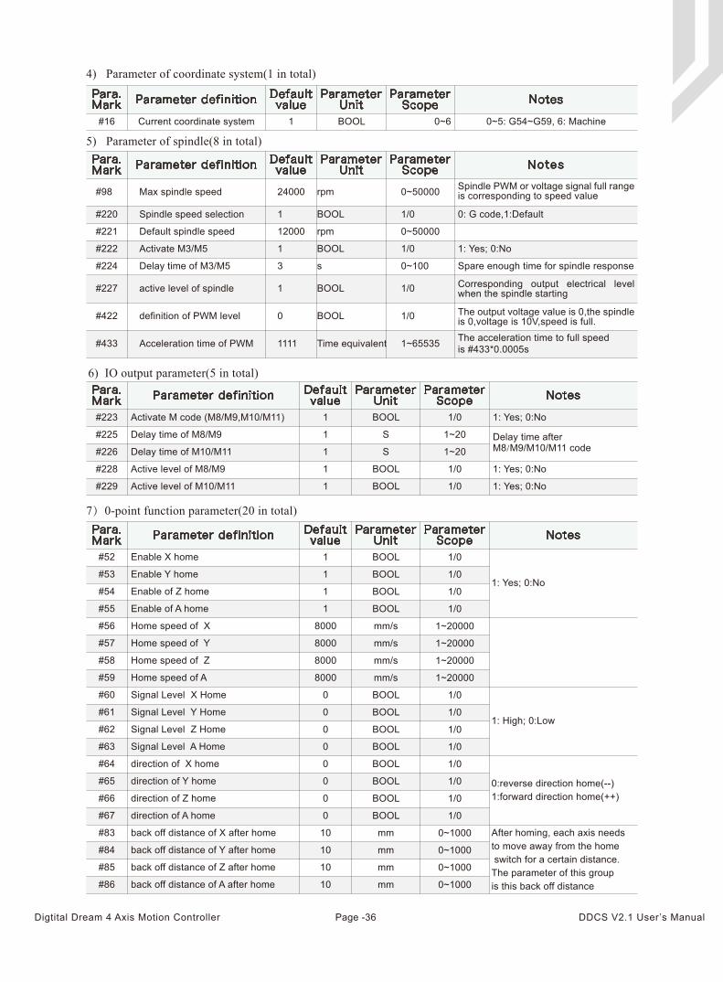
4) Parameter of coordinate system(1 in total)
6) IO output parameter(5 in total)
7)0-point function parameter(20 in total)
5) Parameter of spindle(8 in total)
Activate M code (M8/M9,M10/M11) 1 BOOL 1: Yes; 0:No
Delay time of M8/M9 1 S
Delay time of M10/M11 1 S
Active level of M8/M9 1 BOOL 1: Yes; 0:No
#223
#223
#225
#226
#228
#229 Active level of M10/M11 1 BOOL
1/0
1~20
1~20
1/0
1/0 1: Yes; 0:No
Para.Mark Parameter definition Default
valueParameterUnit
ParameterScope Notes
Delay time after M8/M9/M10/M11 code
#52 Enable X home
1: Yes; 0:No#53 Enable Y home
#54 Enable of Z home
#55 Enable of A home
#56 Home speed of X
#57 Home speed of Y
#58 Home speed of Z
#59 Home speed of A
#60 Signal Level X Home
1: High; 0:Low#61 Signal Level Y Home
#62 Signal Level Z Home
#63 Signal Level A Home
#64 direction of X home
#65 direction of Y home
#66 direction of Z home
#67 direction of A home
#83 back off distance of X after home
#84 back off distance of Y after home
#85 back off distance of Z after home
#86 back off distance of A after home
1
1
1
1
8000
8000
8000
8000
0
0
0
0
0
0
0
0
10
10
10
10
BOOL
BOOL
BOOL
BOOL
mm/s
mm/s
mm/s
mm/s
BOOL
BOOL
BOOL
BOOL
BOOL
BOOL
BOOL
BOOL
mm
mm
mm
mm
1/0
1/0
1/0
1/0
1~20000
1~20000
1~20000
1~20000
1/0
1/0
1/0
1/0
1/0
1/0
1/0
1/0
0~1000
0~1000
0~1000
0~1000
#223Para.Mark Parameter definition Default
valueParameterUnit
ParameterScope Notes
0:reverse direction home(--)1:forward direction home(++)
After homing, each axis needs to move away from the home switch for a certain distance. The parameter of this group is this back off distance
rpm
BOOL 0: G code,1:Default
rpm
BOOL
s
1: Yes; 0:No
Spare enough time for spindle response
BOOL
BOOL
#98
#220
#221
#222
#224
#227
#422
#433
Max spindle speed
Spindle speed selection
Default spindle speed
Activate M3/M5
Delay time of M3/M5
active level of spindle
definition of PWM level
Acceleration time of PWM
24000
1
12000
1
3
1
0
1111 Time equivalent
0~50000
1/0
0~50000
1/0
0~100
1/0
1/0
1~65535 The acceleration time to full speed is #433*0.0005s
Spindle PWM or voltage signal full range is corresponding to speed value
Corresponding output electrical level when the spindle starting
The output voltage value is 0,the spindle is 0,voltage is 10V,speed is full.
Para.Mark Parameter definition Default
valueParameterUnit
ParameterScope Notes
0~5: G54~G59, 6: Machine#16 Current coordinate system 1 BOOL
Para.Mark Parameter definition Default
valueParameterUnit
ParameterScope Notes
0~6
Page -36Digtital Dream 4 Axis Motion Controller DDCS V2.1 User’s Manual
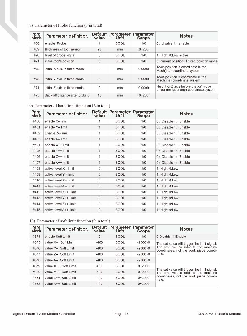
10) Parameter of soft limit function (9 in total)
#374 enable Soft Limit 0 BOOL 1/0 0:Disable, 1:Enable
#375 value X-- Soft Limit -400 BOOL -2000~0
#376 value Y-- Soft Limit -400 BOOL -2000~0
BOOL -2000~0#377 value Z-- Soft Limit -400
#378 value A-- Soft Limit -400 BOOL
BOOL
-2000~0
#379 value X++ Soft Limit 400 0~2000
BOOL 0~2000#380 value Y++ Soft Limit 400
BOOL 0~2000400
BOOL 0~2000400
#381 value Z++ Soft Limit
#382 value A++ Soft Limit
8) Parameter of Probe function (8 in total)
9) Parameter of hard limit function(16 in total)
#68 1 BOOL 1/0 0:disable 1:enable
#69 20 mm 0~200
#70 0 BOOL 1/0 1: High; 0:Low active
#71 0 BOOL 1/0 0: current position; 1:fixed position mode
#72
#73
#74
#75
enable Probe
thickness of tool sensor
level of probe signal
initial tool's position
initial X axis in fixed mode
initial Y axis in fixed mode
initial Z axis in fixed mode
Back off distance after probing
0
0
0
10
mm
mm
mm
mm
0-9999
0-9999
0-9999
0~200
#400 enable X-- limit 1 BOOL 1/0 0:Disable 1:Enable
#401 enable Y-- limit 1 BOOL 1/0 0:Disable 1:Enable
#402 Enable Z-- limit 1 BOOL
BOOL
1/0
1/0
0:Disable 1:Enable
0:Disable 1:Enable#403 enable A-- limit 1
BOOL 1/0 0:Disable 1:Enable1
BOOL 1/0 0:Disable 1:Enable1
BOOL 1/0 0:Disable 1:Enable1
BOOL 1/0 0:Disable 1:Enable1
BOOL 1/00
#404 enable X++ limit
#405 enable Y++ limit
#406 enable Z++ limit
#407 enable A++ limit
#408 active level X-- limit 1: High; 0:Low
BOOL 1/00 1: High; 0:Low
BOOL 1/00 1: High; 0:Low
BOOL 1/00 1: High; 0:Low
BOOL 1/00 1: High; 0:Low
BOOL 1/0 1: High; 0:Low
#409 active level Y-- limit
#410 active level Z-- limit
#411 active level A-- limit
#412 active level X++ limit
#413 active level Y++ limit 0
BOOL 1/0 1: High; 0:Low0
BOOL 1/0 1: High; 0:Low0
#414 active level Z++ limit
#415 active level A++ limit
Tools position X coordinate in the Mach(ine) coordinate system
Tools position Y coordinate in the Mach(ine) coordinate system
The set value will trigger the limit signal. The limit values refer to the machine coordinates, not the work piece coordi-nate.
The set value will trigger the limit signal. The limit values refer to the machine coordinates, not the work piece coordi-nate.
Height of Z axis before the XY move under the Mach(ine) coordinate system
Para.Mark Parameter definition Default
valueParameterUnit
ParameterScope Notes
Para.Mark Parameter definition Default
valueParameterUnit
ParameterScope Notes
Para.Mark Parameter definition Default
valueParameterUnit
ParameterScope Notes
Page -37Digtital Dream 4 Axis Motion Controller DDCS V2.1 User’s Manual
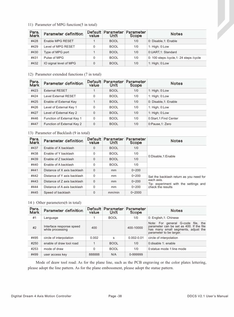
Mode of deaw tool road: As for the plane line, such as the PCB engraving or the color plates lettering, please adopt the line pattern. As for the plane embossment, please adopt the statue pattern.
11) Parameter of MPG function(5 in total)
12) Parameter extended functions (7 in total)
13) Parameter of Backlash (9 in total)
#428 Enable MPG RESET 1 BOOL
BOOL
1/0
1/0
BOOL 1/0
BOOL 1/0
BOOL 1/0
0: Disable,1: Enable
#429 Level of MPG RESET 0 1: High; 0:Low
#430 Type of MPG port 1 0:UART,1: Standard
#431 Pulse of MPG 0
0
0: 100 steps /cycle,1: 24 steps /cycle
#432 IO signal level of MPG 1: High; 0:Low
Para.Mark Parameter definition Default
valueParameterUnit
ParameterScope Notes
BOOL 1/0 1: High; 0:Low
BOOL 1/0
BOOL 1/0
BOOL 1/0
1: High; 0:Low
#423 External RESET 1
#424 Level External RESET 0
#425 Enable of External Key 1 0: Disable,1: Enable
#426 Level of External Key 1 0 1: High; 0:Low
BOOL 1/00
BOOL 1/00
BOOL 1/00
1: High; 0:Low#427 Level of External Key 2
#446 Function of External Key 1 0:Start,1:Find Center
#447 Function of External Key 2 0:Pause,1: Zero
Para.Mark Parameter definition Default
valueParameterUnit
ParameterScope Notes
#437 Enable of X backlash 0 BOOL 1/0
0 BOOL 1/0
0 BOOL 1/0
0 BOOL 1/0
0:Disable,1:Enable#438 Enable of Y backlash
#439 Enable of Z backlash
#440 Enable of A backlash
#441 Distance of X axis backlash 0 mm 0~200
0 mm 0~200
0 mm 0~200
0
0
mm 0~200
0~2000
#442 Distance of Y axis backlash
#443 Distance of Z axis backlash
#444 Distance of A axis backlash
#445 Speed of backlash mm/min
Set the backlash return as you need for each axis.Tip: experiment with the settings and check the results
Para.Mark Parameter definition Default
valueParameterUnit
ParameterScope Notes
14 ) Other parameters(6 in total)
Note: For general G-code file, the parameter can be set as 400. If the file has many small segments, adjust the parameter to be larger.
Interface response speed while processing
Para.Mark Parameter definition Default
valueParameterUnit
ParameterScope Notes
#1 Language 1 BOOL 1/0 0: English,1: Chinese
#2 400-10000
#495 circle of interpolation 0.002
400
s 0.002-0.01 circle of interpolation
#250 enable of draw tool road 1 BOOL 1/0 0:disable 1: enable
#253 mode of draw 0 BOOL
N/A
1/0 0:statue mode 1:line mode
#499 user access key 888888 0-999999
Page -38Digtital Dream 4 Axis Motion Controller DDCS V2.1 User’s Manual
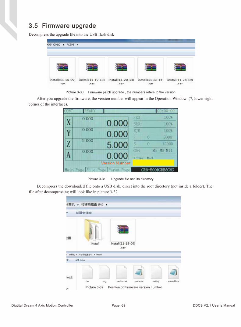
After you upgrade the firmware, the version number will appear in the Operation Window (7, lower right corner of the interface).
Decompress the downloaded file onto a USB disk, direct into the root directory (not inside a folder). The file after decompressing will look like in picture 3-32
3.5 Firmware upgradeDecompress the upgrade file into the USB flash disk
Picture 3-30 Firmware patch upgrade , the numbers refers to the version
Picture 3-32 Position of Firmware version number
Picture 3-31 Upgrade file and its directory
Version Number
Page -39Digtital Dream 4 Axis Motion Controller DDCS V2.1 User’s Manual
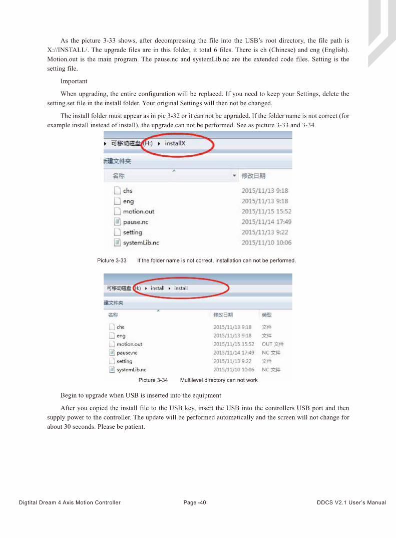
As the picture 3-33 shows, after decompressing the file into the USB’s root directory, the file path is X://INSTALL/. The upgrade files are in this folder, it total 6 files. There is ch (Chinese) and eng (English). Motion.out is the main program. The pause.nc and systemLib.nc are the extended code files. Setting is the setting file.
Important
When upgrading, the entire configuration will be replaced. If you need to keep your Settings, delete the setting.set file in the install folder. Your original Settings will then not be changed.
The install folder must appear as in pic 3-32 or it can not be upgraded. If the folder name is not correct (for example install instead of install), the upgrade can not be performed. See as picture 3-33 and 3-34.
Begin to upgrade when USB is inserted into the equipment
After you copied the install file to the USB key, insert the USB into the controllers USB port and then supply power to the controller. The update will be performed automatically and the screen will not change for about 30 seconds. Please be patient.
Picture 3-33 If the folder name is not correct, installation can not be performed.
Picture 3-34 Multilevel directory can not work
Page -40Digtital Dream 4 Axis Motion Controller DDCS V2.1 User’s Manual
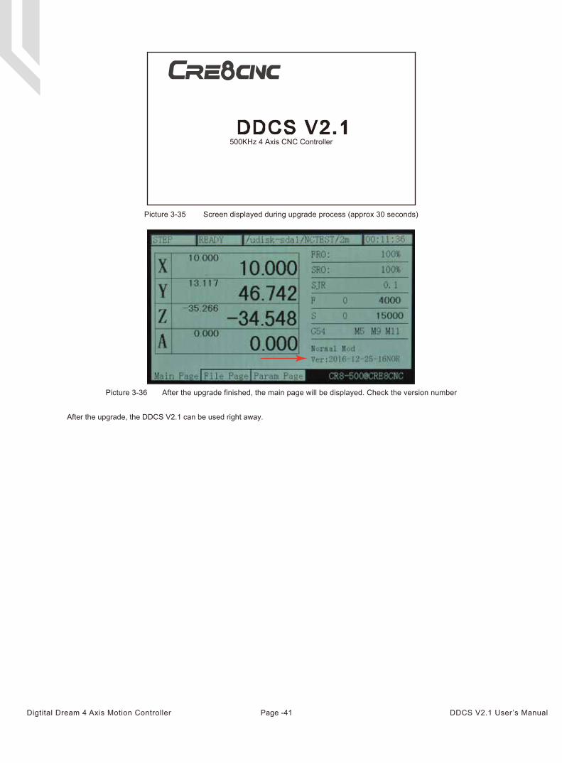
Picture 3-35 Screen displayed during upgrade process (approx 30 seconds)
DDCS V2.1500KHz 4 Axis CNC Controller
Picture 3-36 After the upgrade finished, the main page will be displayed. Check the version number
After the upgrade, the DDCS V2.1 can be used right away.
Page -41Digtital Dream 4 Axis Motion Controller DDCS V2.1 User’s Manual