Embed Size (px)
Citation preview

"Standard Binaries for FPGAs"&
"eBlocks"
Frank Vahid Professor
Department of Computer Science and EngineeringUniversity of California, Riverside
Associate Director, Center for Embedded Computer Systems, UC Irvine
Work supported by the National Science Foundation, the Semiconductor Research Corporation, Xilinx, Intel, and Freescale
Contributing Students: FPGAs: Roman Lysecky (PhD 2005, Asst. Prof. at U. Arizona), Greg Stitt (PhD 2007, Assistant Prof. at U. Florida), Ann Gordon-Ross (Ph.D. 2007, Asst. Prof. at U. Florida), David Sheldon (4th yr PhD), Scott
Sirowy (3rd yr PhD)
eBlocks: Susan Lysecky (PhD 2006, Asst. Prof. at U. Arizona), Ryan Mannion (3rd yr PhD), Shawn Nemetebakshi (MS 2005), plus numerous undergraduate students

Frank Vahid, UC Rivers
ide
2/31
Software is no longer just "instructions" The elephant of software has a (new) tail – FPGA
circuits
Microprocessor instructions
FPGA circuit
s
Software...

Frank Vahid, UC Rivers
ide
3/31
FPGAs: The Quietly Arriving New Software
FPGA (Field-programmable gate array) – thousands of LUTs and switch matrices, plus flip-flops, multipliers, RAMs, etc.
Tools automatically compile circuits into bits that program FPGA
Multi-billion dollar growing industry
Increasingly found in embedded system products – medical devices, basestations, set-top boxes, etc.
a b
a1
a0
4x2 Memory
ab
1010
1110
d1 d0
F G
00011011LUT
F G
2x2 switch matrix
x
y
01
01
1 0a
b
FPGASM
SM
SM
SM
SM
SM
SM
LUT
SM
SM
SM
SM
SM
LUT
01
11
11 01
001111...
10 11
000101...
0200400600800
10001200140016001800
Xilinx Revenue (millions
of $)
1994
1998
2002
2006
Circuit
FPGAs implement circuits as software – bits downloaded into memory

Frank Vahid, UC Rivers
ide
4/31
for (i=0; i < 128; i++) y[i] += c[i] * x[i]......
Why Circuits (Sometimes) Beat Instructions
for (i=0; i < 128; i++) y[i] += c[i] * x[i]......
* * * * * * * * * * * *
+ + + + + +
+ + +
+ +
+
C Code for FIR Filter
Processor Processor
1000’s of instructions Several thousand cycles
Circuit for FIR Filter
Processor FPGA
~ 7 cycles Speedup > 100x
In general, FPGA better due to circuit's concurrency, from bit-level to task level

Frank Vahid, UC Rivers
ide
5/31
Extensive Studies over Past Decade
Large speedups on many important applications Numerous dedicated conferences (FPGA, FCCM,
FPL, ...)
0
10
20
30
40
50
60
Speedup
79.2200500
0
5
10
15
20
25
30
Speedup

Frank Vahid, UC Rivers
ide
6/31
New FPGA Compilers Start from Common Programming Languages
Commercial products appearing in recent years
Good news
BinaryC, C++, Java
ProfilingFPGA Compiler
BinaryBinary
Micro-processor
FPGA
BinaryHDL
BinaryBitstream
Synthesis

Frank Vahid, UC Rivers
ide
7/31
Problem: Best Temporal/Spatial Algorithms Differ
quicksort( array, left, right){ if right > left: pivot= array[left] newpivot = partition(array, left, right, pivot) quicksort(array, left, newpivot -1) quicksort(array, newpivot + 1, right)}
ProcessorProcessor
Bitonic Sorting Network
PlatformAlgorithm
FPGA

Frank Vahid, UC Rivers
ide
8/31
Bigger Problem: Algorithms Matter Even More
For portability, need algorithms that are efficient on both
"Compromise programming"
ProcessorProcessor FPGA
0
1
2
3
4
5
6
7
8
9
10
11
12
13
Speedup
Quicksort
Bitonic Sort

Frank Vahid, UC Rivers
ide
9/31
New FPGA Compilers Start from Common Programming Langauges
BUT – Standard tools/binaries important for "ecosystem"
Countless ideas failed for not respecting the ecosystem
BinaryC, C++, Java
ProfilingFPGA Compiler
BinaryBinary
Micro-processor
FPGA
BinaryBitstream
Languages
ArchitecturesTools
Standard binary

Frank Vahid, UC Rivers
ide
10/31
One Solution: Hide the FPGA
Today's microprocessors use dynamic translation (e.g., x86) Different architectures
hidden For FPGAs:
Transparently translate standard microprocessor binaries to FPGAs Warp Processing
Developed at UCR 2002-present
BinarySW
ProfilingStandard Compiler
BinaryBinary
RISC architecture
Translator
VLIWarchitecture
Translator
FPGAProc.
Translator

Frank Vahid, UC Rivers
ide
11/31
µP
FPGAOn-chip CAD
Warp Processing Background: Basic Idea
Profiler
Initially, software binary loaded into instruction memory
11
I Mem
D$
Mov reg3, 0Mov reg4, 0loop:Shl reg1, reg3, 1Add reg5, reg2, reg1Ld reg6, 0(reg5)Add reg4, reg4, reg6Add reg3, reg3, 1Beq reg3, 10, -5Ret reg4
Software Binary

Frank Vahid, UC Rivers
ide
12/31
µP
FPGAOn-chip CAD
Warp Processing Background: Basic Idea
ProfilerI Mem
D$
Mov reg3, 0Mov reg4, 0loop:Shl reg1, reg3, 1Add reg5, reg2, reg1Ld reg6, 0(reg5)Add reg4, reg4, reg6Add reg3, reg3, 1Beq reg3, 10, -5Ret reg4
Software BinaryMicroprocessor executes
instructions in software binary
22
Time EnergyµP

Frank Vahid, UC Rivers
ide
13/31
µP
FPGAOn-chip CAD
Warp Processing Background: Basic Idea
Profiler
µP
I Mem
D$
Mov reg3, 0Mov reg4, 0loop:Shl reg1, reg3, 1Add reg5, reg2, reg1Ld reg6, 0(reg5)Add reg4, reg4, reg6Add reg3, reg3, 1Beq reg3, 10, -5Ret reg4
Software BinaryProfiler monitors instructions
and detects critical regions in binary
33
Time Energy
Profiler
add
add
add
add
add
add
add
add
add
add
beq
beq
beq
beq
beq
beq
beq
beq
beq
beq
Critical Loop Detected

Frank Vahid, UC Rivers
ide
14/31
µP
FPGAOn-chip CAD
Warp Processing Background: Basic Idea
Profiler
µP
I Mem
D$
Mov reg3, 0Mov reg4, 0loop:Shl reg1, reg3, 1Add reg5, reg2, reg1Ld reg6, 0(reg5)Add reg4, reg4, reg6Add reg3, reg3, 1Beq reg3, 10, -5Ret reg4
Software BinaryOn-chip CAD reads in critical
region44
Time Energy
Profiler
On-chip CAD

Frank Vahid, UC Rivers
ide
15/31
µP
FPGADynamic Part. Module (DPM)
Warp Processing Background: Basic Idea
Profiler
µP
I Mem
D$
Mov reg3, 0Mov reg4, 0loop:Shl reg1, reg3, 1Add reg5, reg2, reg1Ld reg6, 0(reg5)Add reg4, reg4, reg6Add reg3, reg3, 1Beq reg3, 10, -5Ret reg4
Software BinaryOn-chip CAD converts critical region
into control data flow graph (CDFG)55
Time Energy
Profiler
On-chip CAD
loop:reg4 := reg4 + mem[ reg2 + (reg3 << 1)]reg3 := reg3 + 1if (reg3 < 10) goto loop
ret reg4
reg3 := 0reg4 := 0

Frank Vahid, UC Rivers
ide
16/31
µP
FPGADynamic Part. Module (DPM)
Warp Processing Background: Basic Idea
Profiler
µP
I Mem
D$
Mov reg3, 0Mov reg4, 0loop:Shl reg1, reg3, 1Add reg5, reg2, reg1Ld reg6, 0(reg5)Add reg4, reg4, reg6Add reg3, reg3, 1Beq reg3, 10, -5Ret reg4
Software BinaryOn-chip CAD synthesizes
decompiled CDFG to a custom (parallel) circuit
66
Time Energy
Profiler
On-chip CAD
loop:reg4 := reg4 + mem[ reg2 + (reg3 << 1)]reg3 := reg3 + 1if (reg3 < 10) goto loop
ret reg4
reg3 := 0reg4 := 0+ + ++ ++
+ ++
+
+
+
. . .
. . .
. . .

Frank Vahid, UC Rivers
ide
17/31
µP
FPGADynamic Part. Module (DPM)
Warp Processing Background: Basic Idea
Profiler
µP
I Mem
D$
Mov reg3, 0Mov reg4, 0loop:Shl reg1, reg3, 1Add reg5, reg2, reg1Ld reg6, 0(reg5)Add reg4, reg4, reg6Add reg3, reg3, 1Beq reg3, 10, -5Ret reg4
Software BinaryOn-chip CAD maps circuit onto
FPGA77
Time Energy
Profiler
On-chip CAD
loop:reg4 := reg4 + mem[ reg2 + (reg3 << 1)]reg3 := reg3 + 1if (reg3 < 10) goto loop
ret reg4
reg3 := 0reg4 := 0+ + ++ ++
+ ++
+
+
+
. . .
. . .
. . .
CLB
CLB
SM
SM
SM
SM
SM
SM
SM
SM
SM
SM
SM
SM
++
FPGA

Frank Vahid, UC Rivers
ide
18/31
µP
FPGADynamic Part. Module (DPM)
Warp Processing Background: Basic Idea
Profiler
µP
I Mem
D$
Mov reg3, 0Mov reg4, 0loop:Shl reg1, reg3, 1Add reg5, reg2, reg1Ld reg6, 0(reg5)Add reg4, reg4, reg6Add reg3, reg3, 1Beq reg3, 10, -5Ret reg4
Software Binary88
Time Energy
Profiler
On-chip CAD
loop:reg4 := reg4 + mem[ reg2 + (reg3 << 1)]reg3 := reg3 + 1if (reg3 < 10) goto loop
ret reg4
reg3 := 0reg4 := 0+ + ++ ++
+ ++
+
+
+
. . .
. . .
. . .
CLB
CLB
SM
SM
SM
SM
SM
SM
SM
SM
SM
SM
SM
SM
++
FPGA
On-chip CAD replaces instructions in binary to use hardware, causing performance and energy to “warp” by an order of magnitude or more
Mov reg3, 0Mov reg4, 0loop:// instructions that interact with FPGA
Ret reg4
FPGA
Time Energy
Software-only“Warped”
Feasible for repeating or long-running applications

Frank Vahid, UC Rivers
ide
19/31
Recent Warp Results on Multi-Threaded Benchmarks
After translation (may take minutes), huge speedups Even compared to 64-microprocessor system [ Stitt/Vahid CODES/ISSS
2007]
Translation results remembered for later execution

Frank Vahid, UC Rivers
ide
20/31
FPGAs as Software: Challenges and Opportunity
Challenge – Broader definitions of... Compilation, OS, verification, certification, etc.
Opportunity – Can create custom multi-processor architectures just by downloading bits After all, a processor is just another circuit
Xilinx Virtex II Pro can hold dozens of "soft core" 32-bit
processors, in addition to the four "hard core" PowerPCs

Frank Vahid, UC Rivers
ide
21/31
FPGAs and Cyber-Physical Systems Tough to predict future of computing
"Victorian planners in 1830 predicted that by 1930 London street traffic would be bogged down under 25 feet of horse manure."
Are FPGAs to microprocessors what cars were to horses?
Probably not, but perhaps they are what tails are to horses?
We might do well to keep FPGAs in mind as we consider software issues
eBlocks: The Wood-and-Nails of the Electronic Sensor
World
Frank Vahid*Department of Computer Science and Engineering
University of California, [email protected]
http://www.cs.ucr.edu/~vahid* Also with the Center for Embedded Computer Systems at UC Irvine
This work is being supported by the National Science Foundation
Title suggested by a colleague: "eBlocks – Empowering the People"

Frank Vahid, UC Rivers
ide
23/31
Seen this Problem?
Technology everywhere – Why no good solution?
Not!Available

Frank Vahid, UC Rivers
ide
24/31
Shrinking Processor Size/Cost Enables New Solution
Make sensors smarter By adding processor+battery Becomes a "block" easily
connected to other blocks
http://www.templehealth.orgCourtesy of Joe Kahn

Frank Vahid, UC Rivers
ide
25/31
Shrinking Processor Size/Cost Enables New Solution – eBlocks
Existing component view New "eBlock" view
Button yes/no
Light Sensor
yes/no
Magnetic Contact Switch
yes/no
LEDyes/no
yes/no Beeper
Electric Relay
yes/no

Frank Vahid, UC Rivers
ide
26/31
eBlocks Just connect blocks, and they work
No programming knowledge, no electronics knowledge
Button yes/no
LED
yes/no Beeper
yes/noLight Sensor
yes/no

Frank Vahid, UC Rivers
ide
27/31
What's Hard (The Research Part)
(1) Finding right set of building blocks
Toggle
Splitter
Tripper
2-Input Logic
3-Input Logic
Splitter
4-Input Logic
Splitter
Prolong (short)
1 2 3 4 5 6 7 8 9
Prolong (long)
1 2 3 4 5 6 7 8 9
Combine
AND OR
yes no
When A is yes no
B is
then the output is yes
Too many – Overwhelming (too much choice)
2 Yes detector
2 No detector
Too few – Overwhelming (too much configuration)
SuperBlock
1 2 3 4 5 6 7 8 9
AND OR
yes no
When A is B is
then the output is yes
1
2
3 4
5: Splitter
1 2 3 4 5 6 7 8 9
6: ...

Frank Vahid, UC Rivers
ide
28/31
What's Hard (The Research Part) (2) Making the blocks understandable
People NOT likely to read directions Those that do are unlikely to understand
A B Output
no yesno nono yesno yesno yesyes nono yesyes yes
Logic Blockconfigurable DIP switch
A B
Combine
A is yes, B is yesA is yes, B is noA is no, B is yesA is no, B is no
The output should
be yes when:
yes no:
Phrased truth table
yes no
the output should be
A B
When the input is
outCombine
A is yes, B is yesA is yes, B is noA is no, B is yesA is no, B is no
Phrased truth table embedded in sentence
yes no
The output should be
When the input is
out
A B
A BA BA BA B
CombineColored truth table embedded in sentence
Combine
AND OR
yes no
When A is yes no
B is
then the output is yes
Logic Sentence
Example: Combine block
Performed extensive user testing (over 500 students,
kids, and adults) over two years
Most success

Frank Vahid, UC Rivers
ide
29/31
What's Hard (The Research Part) (3) Batteries must last years, yet
performance should appear continuous Blocks are off 99.9% of the time
Mean time between corrupted packets (days)
1
0
Freliability
1 365 730
Block latency (seconds)
1
0
Flatency
0 0.05 0.14
Disconnect response (seconds)
1
0
Fresponsiveness
1800600.25 0.50 1 2 3 4 5 10 30 300 600
Connect response (seconds)
1
0
Fresponsiveness
0.10 600.25 0.50 1 2 3 4 5 10 30 300 600
Latency
Disconnect ResponsivenessReliability
Connect Responsiveness
time
f t f
(a)
(b)
(d)
(c)errorerror
< <
f tf f f< <
interpreted as
Developed theory to map eBlock events to continuous time
Developed custom CAD tool to automatically find the best block parameter settings out of the billions of possibilities

Frank Vahid, UC Rivers
ide
30/31
eBlocks and Embedded Microprocessors
Can greatly simplify coding
Button yes/no
Light Sensor yes/no 1/0
1/0 Micro-
processor

Frank Vahid, UC Rivers
ide
31/31
eBlocks Prototypes
>100 prototypes, size of deck of cards (trend: smaller) 2-3 years on 2 AA batteries (trend: longer) Can communicate via wire >1.5 miles, 150 ft wireless Integer blocks too
Early apps: hearing/vision impaired, ageing parents, middle-school projects
Support for advanced users
Frank Vahid, UC Rivers
ide
32/31
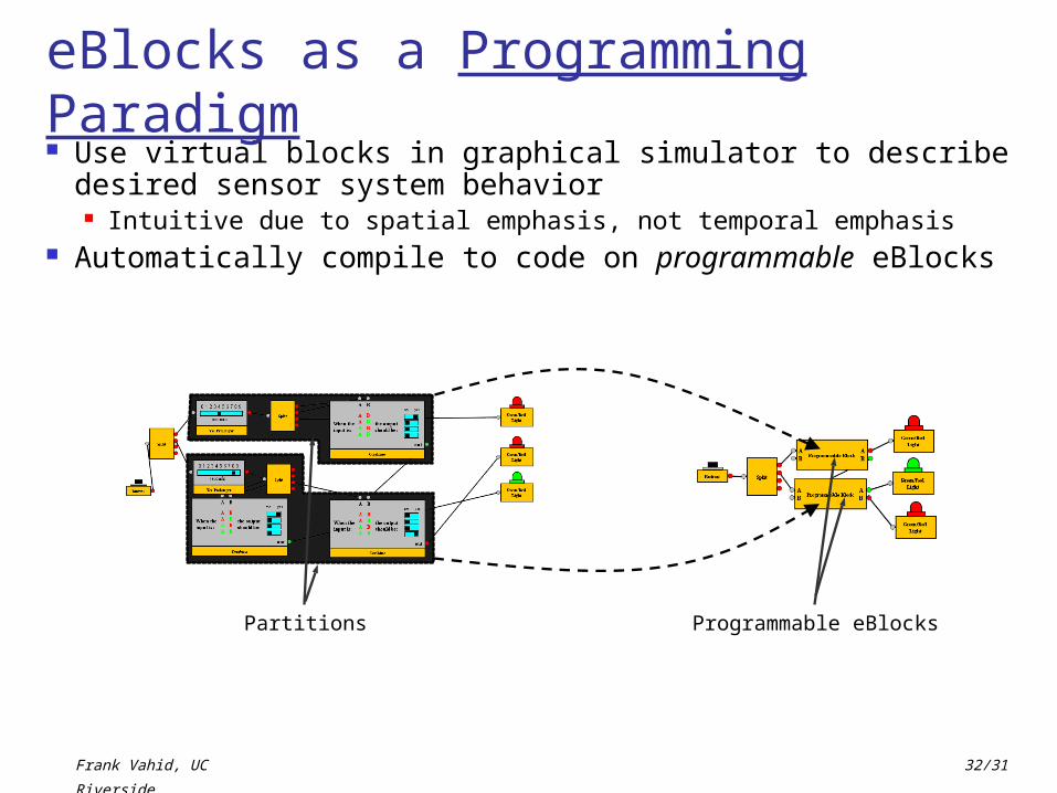
Use virtual blocks in graphical simulator to describe desired sensor system behavior Intuitive due to spatial emphasis, not temporal emphasis
Automatically compile to code on programmable eBlocks
eBlocks as a Programming Paradigm
Programmable eBlocksPartitions

Frank Vahid, UC Rivers
ide
33/31
eBlock Tool Generates Code Tool generates C code
automatically#include <pic.h>#include “sci.h”
#include “io.h”
#include “constants.h”
Unsigned char data_val = ERROR;
...
main(void) {
unsigned I, j;
TRISB = 0;
...
}
main(void) {
ORTA = 0xff;
CMCON = 0x07;
TRISA = 0x00;
TRISB = 0x02;
asm("CLRWDT");
...
}
C Code
Download code to block with click of a button Ordinary users can “write” programs in
minutes Spatial vs. temporally-oriented language
20 high school graduates: eBlocks (spatial) vs. LEGO Mindstorms (temporal), 6 example systems, 40 minutes to build
Programmable eBlock
TypeAverage Success
Rate
Mindstorms 0%
eBlocks 54%

Frank Vahid, UC Rivers
ide
34/31
eBlocks 1998: Simple Problem
Garage door open at night
No simple solution Off-the-shelf solutions
costly, hard to find, and/or not customizable
Alarm system cost – overkill
Connecting existing sensors, logic, transmit/receive, LEDs is hard
Electronics, programming 2-week project: 70%
EE/CS unable Countless similar
applications go unrealized Why can't I just connect
those components like "LegoTM" blocks?
LEDreceive
contact switch
light sensor
AND
transmit

Frank Vahid, UC Rivers
ide
35/31
eBlocks Example "Garage Open at Night" detector <10 minutes to build
Need to indicate garage open at night – use LED block
LEDDetect night-time – use Light Sensor block
Light Sensor
Detect garage door open – use Contact Switch block
Magnetic Contact Switch
Plug pieces together and the system is
done!
Use Combine block to combine light sensor and contact switch into one
Combine
AND OR
yes no
When A is yes no
B is
then the output is yes

Frank Vahid, UC Rivers
ide
36/31
Graphical Simulator
Welcome to the eBlocks Simulator! In this area, you’ll find helpful hints on creating your own designs.
Click and drag an eBlock off of the “Available eBlocks” panel to add it to your design.To connect two blocks, click and drag from an output port (colored circle) to an input port (gray circle).A connection can be destroyed by clicking on a connected port.To move a block around the workspace, click and drag its orange area.Blocks can be moved into the trash can to delete them.Green circles indicate that the port is sending a yes, red circles indicate that the port is sending a no, yellowCircles indicate that the port is sending an error signal, and gray circles denote an input port.
User specifies and tests block design
Java-based simulator User chooses
between pallets Blocks added by
dragging User is able to
configure various blocks by clicking on switches
Connections created by drawing lines between blocks
User can create, experiment, test and configure design
Available eBlocks
Advanced ModeHide this panel
Compute/Communications
Prolonger
1 2 3 4 5 6 7 8 9
seconds
Once Yes, Stays Yes
rst
in
Toggle
Combine
AND OR
yes no
When A is yes no
B is
then the output is yes
Green/Red Light
Beeper
Output
Motion Sensor
Yes/No
Button
Light Sensor
SensorsLight
Sensor
Available eBlocks
Advanced ModeHide this panel
Green/Red Light
Beeper
Output
Motion Sensor
Yes/No
Button
Light Sensor
Sensors
Compute/Communications
Prolonger
1 2 3 4 5 6 7 8 9
seconds
Once Yes, Stays Yes
rst
in
Toggle
Combine
AND OR
yes no
When A is yes no
B is
then the output is yes
Available eBlocks
Advanced ModeHide this panel
Compute/Communications
Prolonger
1 2 3 4 5 6 7 8 9
seconds
Once Yes, Stays Yes
rst
in
Toggle
Combine
AND OR
yes no
When A is yes no
B is
then the output is yes
Motion Sensor
Yes/No
Button
Light Sensor
Sensors
Green/Red Light
Beeper
Output
Beeper
Combine
AND OR
yes no
When A is yes no
B is
then the output is yes
Light Sensor
Button

Frank Vahid, UC Rivers
ide
37/31
Graphical Simulator
Welcome to the eBlocks Simulator! In this area, you’ll find helpful hints on creating your own designs.
Click and drag an eBlock off of the “Available eBlocks” panel to add it to your design.To connect two blocks, click and drag from an output port (colored circle) to an input port (gray circle).A connection can be destroyed by clicking on a connected port.To move a block around the workspace, click and drag its orange area.Blocks can be moved into the trash can to delete them.Green circles indicate that the port is sending a yes, red circles indicate that the port is sending a no, yellowCircles indicate that the port is sending an error signal, and gray circles denote an input port.
User specifies and tests block design
Java-based simulator User chooses
between pallets
Available eBlocks
Advanced ModeHide this panel
Compute/Communications
Prolonger
1 2 3 4 5 6 7 8 9
seconds
Once Yes, Stays Yes
rst
in
Toggle
Combine
AND OR
yes no
When A is yes no
B is
then the output is yes
Green/Red Light
Beeper
Output
Motion Sensor
Yes/No
Button
Light Sensor
Sensors
Available eBlocks
Advanced ModeHide this panel
Compute/Communications
Prolonger
1 2 3 4 5 6 7 8 9
seconds
Once Yes, Stays Yes
rst
in
Toggle
Combine
AND OR
yes no
When A is yes no
B is
then the output is yes
Motion Sensor
Yes/No
Button
Light Sensor
Sensors
Green/Red Light
Beeper
Output
Available eBlocks
Advanced ModeHide this panel
Green/Red Light
Beeper
Output
Motion Sensor
Yes/No
Button
Light Sensor
Sensors
Compute/Communications
Prolonger
1 2 3 4 5 6 7 8 9
seconds
Once Yes, Stays Yes
rst
in
Toggle
Combine
AND OR
yes no
When A is yes no
B is
then the output is yes

Frank Vahid, UC Rivers
ide
38/31
Graphical Simulator
Welcome to the eBlocks Simulator! In this area, you’ll find helpful hints on creating your own designs.
Click and drag an eBlock off of the “Available eBlocks” panel to add it to your design.To connect two blocks, click and drag from an output port (colored circle) to an input port (gray circle).A connection can be destroyed by clicking on a connected port.To move a block around the workspace, click and drag its orange area.Blocks can be moved into the trash can to delete them.Green circles indicate that the port is sending a yes, red circles indicate that the port is sending a no, yellowCircles indicate that the port is sending an error signal, and gray circles denote an input port.
User specifies and tests block design
Java-based simulator User chooses
between pallets Blocks added by
dragging
Available eBlocks
Advanced ModeHide this panel
Compute/Communications
Prolonger
1 2 3 4 5 6 7 8 9
seconds
Once Yes, Stays Yes
rst
in
Toggle
Combine
AND OR
yes no
When A is yes no
B is
then the output is yes
Green/Red Light
Beeper
Output
Motion Sensor
Yes/No
Button
Light Sensor
Sensors
Available eBlocks
Advanced ModeHide this panel
Green/Red Light
Beeper
Output
Compute/Communications
Prolonger
1 2 3 4 5 6 7 8 9
seconds
Once Yes, Stays Yes
rst
in
Toggle
Combine
AND OR
yes no
When A is yes no
B is
then the output is yes
Motion Sensor
Yes/No
Button
Light Sensor
Sensors
Button

Frank Vahid, UC Rivers
ide
39/31
Graphical Simulator
Welcome to the eBlocks Simulator! In this area, you’ll find helpful hints on creating your own designs.
Click and drag an eBlock off of the “Available eBlocks” panel to add it to your design.To connect two blocks, click and drag from an output port (colored circle) to an input port (gray circle).A connection can be destroyed by clicking on a connected port.To move a block around the workspace, click and drag its orange area.Blocks can be moved into the trash can to delete them.Green circles indicate that the port is sending a yes, red circles indicate that the port is sending a no, yellowCircles indicate that the port is sending an error signal, and gray circles denote an input port.
User specifies and tests block design
Java-based simulator User chooses
between pallets Blocks added by
dragging
Available eBlocks
Advanced ModeHide this panel
Compute/Communications
Prolonger
1 2 3 4 5 6 7 8 9
seconds
Once Yes, Stays Yes
rst
in
Toggle
Combine
AND OR
yes no
When A is yes no
B is
then the output is yes
Green/Red Light
Beeper
Output
Motion Sensor
Yes/No
Button
Light Sensor
Sensors
Button
Light Sensor

Frank Vahid, UC Rivers
ide
40/31
Graphical Simulator
Welcome to the eBlocks Simulator! In this area, you’ll find helpful hints on creating your own designs.
Click and drag an eBlock off of the “Available eBlocks” panel to add it to your design.To connect two blocks, click and drag from an output port (colored circle) to an input port (gray circle).A connection can be destroyed by clicking on a connected port.To move a block around the workspace, click and drag its orange area.Blocks can be moved into the trash can to delete them.Green circles indicate that the port is sending a yes, red circles indicate that the port is sending a no, yellowCircles indicate that the port is sending an error signal, and gray circles denote an input port.
User specifies and tests block design
Java-based simulator User chooses
between pallets Blocks added by
dragging
Available eBlocks
Advanced ModeHide this panel
Compute/Communications
Prolonger
1 2 3 4 5 6 7 8 9
seconds
Once Yes, Stays Yes
rst
in
Toggle
Combine
AND OR
yes no
When A is yes no
B is
then the output is yes
Green/Red Light
Beeper
Output
Motion Sensor
Yes/No
Button
Light Sensor
Sensors
Button
Light Sensor
Available eBlocks
Advanced ModeHide this panel
Green/Red Light
Beeper
Output
Motion Sensor
Yes/No
Button
Light Sensor
Sensors
Compute/Communications
Prolonger
1 2 3 4 5 6 7 8 9
seconds
Once Yes, Stays Yes
rst
in
Toggle
Combine
AND OR
yes no
When A is yes no
B is
then the output is yes
Combine
AND OR
yes no
When A is yes no
B is
then the output is yes

Frank Vahid, UC Rivers
ide
41/31
Graphical Simulator
Welcome to the eBlocks Simulator! In this area, you’ll find helpful hints on creating your own designs.
Click and drag an eBlock off of the “Available eBlocks” panel to add it to your design.To connect two blocks, click and drag from an output port (colored circle) to an input port (gray circle).A connection can be destroyed by clicking on a connected port.To move a block around the workspace, click and drag its orange area.Blocks can be moved into the trash can to delete them.Green circles indicate that the port is sending a yes, red circles indicate that the port is sending a no, yellowCircles indicate that the port is sending an error signal, and gray circles denote an input port.
User specifies and tests block design
Java-based simulator User chooses
between pallets Blocks added by
dragging
Available eBlocks
Advanced ModeHide this panel
Compute/Communications
Prolonger
1 2 3 4 5 6 7 8 9
seconds
Once Yes, Stays Yes
rst
in
Toggle
Combine
AND OR
yes no
When A is yes no
B is
then the output is yes
Green/Red Light
Beeper
Output
Motion Sensor
Yes/No
Button
Light Sensor
Sensors
Button
Light Sensor
Available eBlocks
Advanced ModeHide this panel
Green/Red Light
Beeper
Output
Motion Sensor
Yes/No
Button
Light Sensor
Sensors
Compute/Communications
Prolonger
1 2 3 4 5 6 7 8 9
seconds
Once Yes, Stays Yes
rst
in
Toggle
Combine
AND OR
yes no
When A is yes no
B is
then the output is yes
Combine
AND OR
yes no
When A is yes no
B is
then the output is yes
Available eBlocks
Advanced ModeHide this panel
Compute/Communications
Prolonger
1 2 3 4 5 6 7 8 9
seconds
Once Yes, Stays Yes
rst
in
Toggle
Combine
AND OR
yes no
When A is yes no
B is
then the output is yes
Motion Sensor
Yes/No
Button
Light Sensor
Sensors
Green/Red Light
Beeper
Output
Beeper

Frank Vahid, UC Rivers
ide
42/31
Combine
AND OR
yes no
When A is yes no
B is
then the output is yes
Graphical Simulator
Welcome to the eBlocks Simulator! In this area, you’ll find helpful hints on creating your own designs.
Click and drag an eBlock off of the “Available eBlocks” panel to add it to your design.To connect two blocks, click and drag from an output port (colored circle) to an input port (gray circle).A connection can be destroyed by clicking on a connected port.To move a block around the workspace, click and drag its orange area.Blocks can be moved into the trash can to delete them.Green circles indicate that the port is sending a yes, red circles indicate that the port is sending a no, yellowCircles indicate that the port is sending an error signal, and gray circles denote an input port.
User specifies and tests block design
Java-based simulator User chooses
between pallets Blocks added by
dragging User is able to
configure various blocks by clicking on switches
Available eBlocks
Advanced ModeHide this panel
Compute/Communications
Prolonger
1 2 3 4 5 6 7 8 9
seconds
Once Yes, Stays Yes
rst
in
Toggle
Combine
AND OR
yes no
When A is yes no
B is
then the output is yes
Green/Red Light
Beeper
Output
Motion Sensor
Yes/No
Button
Light Sensor
Sensors
Button
Light Sensor
Available eBlocks
Advanced ModeHide this panel
Green/Red Light
Beeper
Output
Motion Sensor
Yes/No
Button
Light Sensor
Sensors
Compute/Communications
Prolonger
1 2 3 4 5 6 7 8 9
seconds
Once Yes, Stays Yes
rst
in
Toggle
Combine
AND OR
yes no
When A is yes no
B is
then the output is yes
Available eBlocks
Advanced ModeHide this panel
Compute/Communications
Prolonger
1 2 3 4 5 6 7 8 9
seconds
Once Yes, Stays Yes
rst
in
Toggle
Combine
AND OR
yes no
When A is yes no
B is
then the output is yes
Motion Sensor
Yes/No
Button
Light Sensor
Sensors
Green/Red Light
Beeper
Output
Beeper

Frank Vahid, UC Rivers
ide
43/31
Graphical Simulator
Welcome to the eBlocks Simulator! In this area, you’ll find helpful hints on creating your own designs.
Click and drag an eBlock off of the “Available eBlocks” panel to add it to your design.To connect two blocks, click and drag from an output port (colored circle) to an input port (gray circle).A connection can be destroyed by clicking on a connected port.To move a block around the workspace, click and drag its orange area.Blocks can be moved into the trash can to delete them.Green circles indicate that the port is sending a yes, red circles indicate that the port is sending a no, yellowCircles indicate that the port is sending an error signal, and gray circles denote an input port.
User specifies and tests block design
Java-based simulator User chooses
between pallets Blocks added by
dragging User is able to
configure various blocks by clicking on switches
Connections created by drawing lines between blocks
Available eBlocks
Advanced ModeHide this panel
Compute/Communications
Prolonger
1 2 3 4 5 6 7 8 9
seconds
Once Yes, Stays Yes
rst
in
Toggle
Combine
AND OR
yes no
When A is yes no
B is
then the output is yes
Green/Red Light
Beeper
Output
Motion Sensor
Yes/No
Button
Light Sensor
Sensors
Button
Light Sensor
Available eBlocks
Advanced ModeHide this panel
Green/Red Light
Beeper
Output
Motion Sensor
Yes/No
Button
Light Sensor
Sensors
Compute/Communications
Prolonger
1 2 3 4 5 6 7 8 9
seconds
Once Yes, Stays Yes
rst
in
Toggle
Combine
AND OR
yes no
When A is yes no
B is
then the output is yes
Available eBlocks
Advanced ModeHide this panel
Compute/Communications
Prolonger
1 2 3 4 5 6 7 8 9
seconds
Once Yes, Stays Yes
rst
in
Toggle
Combine
AND OR
yes no
When A is yes no
B is
then the output is yes
Motion Sensor
Yes/No
Button
Light Sensor
Sensors
Green/Red Light
Beeper
Output
Beeper
Combine
AND OR
yes no
When A is yes no
B is
then the output is yes