Embed Size (px)
Citation preview
STANDARD CONSTRUCTION SPECIFICATIONS
WEST DES MOINES WATER WORKS WEST DES MOINES, IOWA
Effective date: August 11, 2008 See paragraph 4.A.4. on page 1 - 2
Prepared by West Des Moines Water Works
West Des Moines, Iowa

STANDARD CONSTRUCTION SPECIFICATIONS
WEST DES MOINES WATER WORKS WEST DES MOINES, IOWA
Specifications included:
Water Mains and Appurtenances Water Service Connections Fire Protection Connections
Water Metering
Sample Contract Documents
Standard Drawings
I hereby certify that these standard specifications were prepared by me or under my direct supervision and that I am a duly Registered Professional Engineer under the laws of the State of Iowa.
Signed: Date: Jerald W. Stevens, P.E. Iowa Registration No. 9804 My Registration Expires December 31, 2009
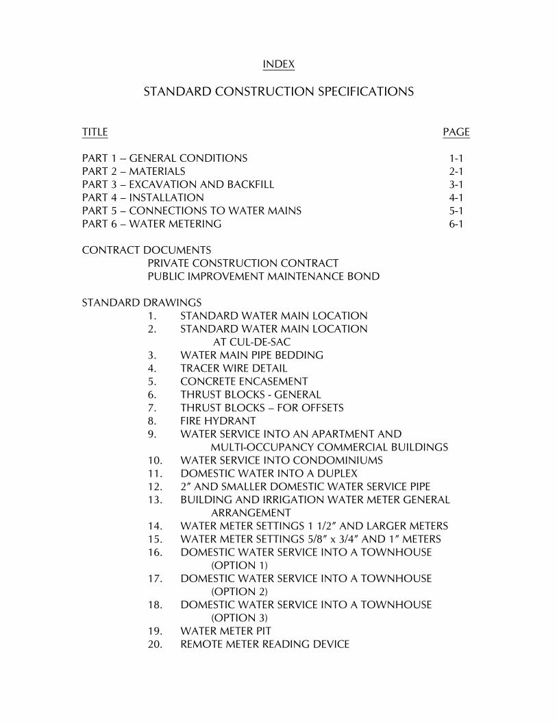
INDEX
STANDARD CONSTRUCTION SPECIFICATIONS
TITLE
PAGE
PART 1 -- GENERAL CONDITIONS 1-1 PART 2 – MATERIALS 2-1 PART 3 – EXCAVATION AND BACKFILL 3-1 PART 4 – INSTALLATION 4-1 PART 5 – CONNECTIONS TO WATER MAINS 5-1 PART 6 – WATER METERING 6-1 CONTRACT DOCUMENTS PRIVATE CONSTRUCTION CONTRACT PUBLIC IMPROVEMENT MAINTENANCE BOND STANDARD DRAWINGS 1. STANDARD WATER MAIN LOCATION 2. STANDARD WATER MAIN LOCATION AT CUL-DE-SAC 3. WATER MAIN PIPE BEDDING 4. TRACER WIRE DETAIL 5. CONCRETE ENCASEMENT 6. THRUST BLOCKS - GENERAL 7. THRUST BLOCKS – FOR OFFSETS 8. FIRE HYDRANT
9. WATER SERVICE INTO AN APARTMENT AND MULTI-OCCUPANCY COMMERCIAL BUILDINGS
10. WATER SERVICE INTO CONDOMINIUMS 11. DOMESTIC WATER INTO A DUPLEX 12. 2” AND SMALLER DOMESTIC WATER SERVICE PIPE 13. BUILDING AND IRRIGATION WATER METER GENERAL ARRANGEMENT 14. WATER METER SETTINGS 1 1/2” AND LARGER METERS 15. WATER METER SETTINGS 5/8” x 3/4” AND 1” METERS 16. DOMESTIC WATER SERVICE INTO A TOWNHOUSE (OPTION 1) 17. DOMESTIC WATER SERVICE INTO A TOWNHOUSE (OPTION 2) 18. DOMESTIC WATER SERVICE INTO A TOWNHOUSE (OPTION 3) 19. WATER METER PIT 20. REMOTE METER READING DEVICE
General Conditions
1-1
PART 1 – GENERAL CONDITIONS
INDEX
1. FORM 9. CONSTRUCTION IN HIGHWAY 2. DEFINITION OF TERMS RIGHT-OF-WAY 3. INTENT 10. CONSTRUCTION ACROSS PAVED 4. APPLICABILITY OF STREETS SPECIFICATIONS 11. INFORMATION FOR WATER 5. INTERPRETATION WORKS 6. STANDARDS AND CODES 12. RESPONSIBILITY OF 7. GENERAL REQUIREMENT SUBDIVIDER OR DEVELOPER 8. CONSTRUCTION IN 13. INSURANCE BY CONTRACTOR RAILROAD RIGHT-OF-WAY 1. FORM A. These Standard Specifications are in outline form and contain incomplete sentences. Omission of words or phrases is intentional. Supply omitted words or phrases by inference. 2. DEFINITION OF TERMS
A. “Water Works” shall mean the West Des Moines Water Works, acting
through its Board of Trustees or an authorized representative of the Board of Trustees.
B. “City” shall mean the City of West Des Moines, Iowa, acting through the
City Council or an authorized representative of the City Council. C. “Subdivider” shall mean any person, firm, partnership, corporation,
association, estate, trust or any group or combination acting as a unit, or any agent thereof, dividing or proposing to divide land so as to constitute a subdivision as defined by subdivision ordinances of the City of West Des Moines or Chapter 354, Code of Iowa.
D. “Developer” shall mean any person, firm, partnership, corporation,
association, estate, trust or any group or a combination acting as a unit, or any agent thereof, developing or proposing to develop land as a
commercial or industrial site, including multifamily residential sites, all as defined by the zoning ordinances of the City of West Des Moines. E. “Contractor” shall mean any person, firm, partnership, association or
corporation installing water mains, water service connections, fire protection connections and appurtenances for the subdivider or developer.
General Conditions
1-2
F. “Standard Drawings” shall mean the drawings bound with these
specifications. 3. INTENT A. To set forth requirements of performance, type of structure desired and
standards of materials and construction for installation of water mains, water service connections, fire protection and connections and water metering arrangements and appurtenances to be connected to the West Des Moines Water Works water distribution system.
B. To assist in implementing portions of subdivision ordinances of the City of
West Des Moines. C. To assist in implementing rules of the Board of Trustees of the West Des
Moines Water Works . D. To supplement the provisions of “Standard Construction Specifications for
Subdivisions” of the City of West Des Moines. E. To insure that water mains, water service connections, fire protection
connections and water metering arrangements and appurtenances meet requirements of the City of West Des Moines, West Des Moines Water Works and Iowa Department of Natural Resources (IDNR).
F. To supersede all previous specifications of the Water Works.
4. APPLICABILITY OF SPECIFICATIONS A. These specifications shall apply to the following: 1. Water mains, water service connections and appurtenances to be installed, upgraded or replaced in any type of subdivision. 2. Water service connections, fire protection connections and
appurtenances to be installed, upgraded or replaced in a commercial or industrial site.
3. Other locations where unmetered water supplied by the West Des
Moines Water Works will flow through the proposed pipe to be installed, upgraded or replaced.
4. These specifications shall apply to any of the above types of work on which construction is started on or after September 1, 2008.
General Conditions
1-3
B. These specifications shall not apply to repair or abandonment work on
existing water mains, water service connections or fire protection connections.
C. In the event of a conflict between these specifications and an applicable
building code, the provisions of the more restrictive document shall apply.
5. INTERPRETATION
A. Water Works will answer questions regarding interpretation of intended meaning of specifications; its interpretation shall be accepted as final. 6. STANDARDS AND CODES A. Do work in accordance with best present-day installation and construction practices. B. Conform with standards and codes of the State of Iowa, rules of the Iowa
Department of Natural Resources, the Iowa Department of Labor, ordinances of the City of West Des Moines and rules of the West Des Moines Water Works.
7. GENERAL REQUIREMENTS A. Design water mains and appurtenances in accordance with the following standards: 1. Iowa Department of Natural Resources Standards and Requirements. 2. Recommended Standards for Water Works in the Statewide Urban
Design and Specifications (SUDAS). 3. City of West Des Moines Comprehensive Plan. 4. West Des Moines Water Works Water Supply, Storage and
Distribution Study. B. Submit plans of proposed construction for review by Water Works. 1. Submit plans to West Des Moines Water Works, 4200 Mills Civic
Parkway, Suite 1D, West Des Moines, Iowa 50265. a. Plan shall be certified by a registered professional engineer as
contemplated by Chapter 542 B, Code of Iowa.
General Conditions
1-4
2. Submit one (1) copy of applicable schedules for Iowa Department of Natural Resources Water Supply Section Construction Permit Application. 3. Submit one (1) copy of IDNR Water Supply Service Agreement. C. Developer or Subdivider will submit plans to IDNR for approval and pay applicable fees. 1. Begin no construction prior to issuance of construction permit. D. Make no connection to existing water distribution system or work in public right-of-way until authorized by Water Works. 1. Obtain street excavation permit from City. E. Extend water main to plat, site plan or property boundary, to next street or water main, or as directed by Water Works. 1. Permanent dead-end mains will not be permitted, except in a cul-de-sac. F. Materials and accessories to be furnished by subdivider or developer include pipe, valves, valve boxes, tapping valves and sleeves, complete hydrant installations, including hydrant, auxiliary valve and valve box, anchoring fittings and appurtenances. 1. Provide excavation and backfill and pipe for water service pipes and appurtenances between water main and curb valve. G. Excavation, pipe laying, backfilling, testing and disinfecting of water mains, water service connections and fire protection connections and appurtenances will be subject to inspection by a representative of Water Works to ensure compliance with specifications. 1. When work will be accepted for ownership and maintenance by Water Works, inspection shall be substantially full-time. 2. When work will not be accepted for ownership and maintenance by Water Works, inspection shall be only as required to establish that materials meet these specifications, that fire hydrants are installed and painted as required by these specifications and the City Fire Code and that completed installation passes pressure and leakage testing. Water Works will also observe disinfection procedures.
General Conditions
1-5
3. The cost of inspection and the testing set out in PART 3 – EXCAVATION AND BACKFILL shall be paid prior to acceptance
of the work by the Water Works, or if the work is not to be accepted prior to the first occupancy of the building or site. H. Upon completion of construction, complete the administrative requirements set out in paragraph 11.B on page 1-6. 8. CONSTRUCTION IN RAILROAD RIGHT-OF-WAY A. Submit detailed plans of construction operations including sheeting, shoring and bracing, for approval of Railroad and Water Works. B. Start no work in Railroad right-of-way until plans required above and permission is granted by Railroad and Water Works. C. Notify Railroad Division Superintendent and Water Works not less than one week in advance of proposed time for performance of any construction work in Railroad right-of-way or preparatory work thereto. D. Confer with Railroad representative concerning requirements for operation and general safety regulations. E. Conduct work in manner satisfactory to Railroad and exercise care not to damage Railroad property or interfere with operations of Railroad. F. The Railroad Division Superintendent or a representative will have jurisdiction over safety for operations of Railroad. The decision of the Railroad as to procedures which may affect safety of Railroad operations shall be final. G. Do not stockpile or store excess material or debris in Railroad right-of-way. H. Submit Railroad’s certificate of acceptability to Water Works after construction; Water Works will accept work only upon approval of Railroad. 9. CONSTRUCTION IN HIGHWAY RIGHT-OF-WAY A. Obtain approval of Iowa Department of Transportation (Iowa DOT) and Federal Highway Administration; file one copy of permit with Water Works and insure that one copy is at job site at all times. B. Comply with applicable sections of current edition of Iowa DOT “Utility Accommodation Policy”.
General Conditions
1-6
C. Comply with safety regulations of Iowa DOT. D. Work in right-of-way is subject to inspection by Iowa DOT; Water Works will accept work only upon approval of Iowa DOT. 10. CONSTRUCTION ACROSS PAVED STREETS A. Construct water main, water service connection and fire protection pipes across existing paved streets as directed by City and Water Works. 1. Casing pipe, auguring, removal of whole or half panels of pavement or other methods may be required. a. Use casing pipe specified in PART 2 – MATERIALS. 2. Excavation below existing paved streets to make connections or repairs requires removal and replacement of street surfacing. Undercutting paved streets is not permitted. B. Obtain street excavation permit from City. 11. INFORMATION FOR WATER WORKS A. Seven days prior to start of construction, provide two copies of following Information: 1. Certificate of Insurance made in favor of City and Water Works; include Railroad Protective Liability coverage, if appropriate. 2. Contractor may provide one Certificate of Insurance covering all projects contemplated in a construction season or policy period, if
desired. B. After construction is complete, provide the following:
1. One 12” x 18” x 0.004” thick Mylar copy and an electronic copy in
MicroStation format of as-built plans, including locations of water mains and appurtenances installed; measure to lot corners or other suitable monuments.
a. Produce Mylar copy from original tracing of as-built drawing:
photographically reduce to 12” x 18” size; provide bar graph scale to permit scaled measurements on reduced drawing.
General Conditions
1-7
C. For work which will be accepted for ownership and maintenance responsibility by Water Works, also provide: 1. Two copies of a four-year maintenance bond in the amount of
100% of the value of the completed work, except water service connections and fire protection connections; show value of water main work separately from other work; make bond in favor of Water Works.
a. Execute bond on form provided or approved by Water Works; see Contact Documents for sample form.
2. One copy of a tabulation showing installed lengths and costs of each diameter of water main and the number and total cost of hydrants installed.
a. Pipe cost should include the costs of valves, valve boxes, fittings
and other items appropriate to each diameter of pipe.
b. Tabulation should total 100% of value of work, except water service connections and fire protection connections.
D. Acceptance of work for ownership and maintenance by Water Works is contingent upon compliance with these specifications, including administrative requirements stated herein. E. Non-compliance with these specifications, including administrative requirements stated herein, shall result in denial of water service to work determined by Water Works to be non-compliant. 12. RESPONSIBILITY OF SUBDIVIDER OR DEVELOPER A. Protection of privately owned property from damage due to construction operations. B. Protection of existing public improvements, including utility lines, pipes,
cables, poles, street pavement, sewers, water mains, water service connections and fire protection connections and appurtenances from damage due to construction operations.
C. Coordination with building contractor to protect new water service connection and fire protection connection piping and appurtenances until the first customer applies for water service at house or other building.
General Conditions
1-8
13. INSURANCE BY CONTRACTOR A. The Contractor shall purchase and maintain insurance to protect Contractor and Water Works against all hazards enumerated herein for all work. All policies shall be in the amounts, form and companies satisfactory to the Water Works. B. All certificates of insurance required herein shall state that thirty (30)
days written notice will be given to the Water Works before the policy is cancelled or changed. All certificates of insurance shall be delivered to
the Water Works prior to the time that any construction operations are started. C. All of said Contractor’s certificates of insurance shall be written by
insurance companies authorized to do business in the State of Iowa. D. The Contractor shall purchase and maintain such insurance as will protect
Contractor from claims set forth below which may arise out of or result from the Contractor’s operations, whether such operations be by Contractor or by any sub-contractor, or by anyone directly or indirectly employed by any of them, or by anyone for whose acts any of them may be liable.
1. Claims under Workers’ Compensation, Disability Benefit and other
similar employee benefit acts. 2. Claims for damages because of bodily injury, occupational sickness or
disease, or death of his employees. 3. Claims for damages because of bodily injury, sickness or disease or death of any person other than Contractor’s employees. 4. Claims for damages insured by usual personal injury liability coverage
which are sustained (1) by any person as a result of a result of an offense directly or indirectly related to the employment of such
person by the Contractor, or (2) by any other person. 5. Claims for damages, other than to the work itself, because of
injury to or destruction of tangible property, including loss of use resulting therefrom.
6. Claims for damages because of bodily injury or death of any person
or property damage arising out of the ownership, maintenance or use of any motor vehicle.
General Conditions
1-9
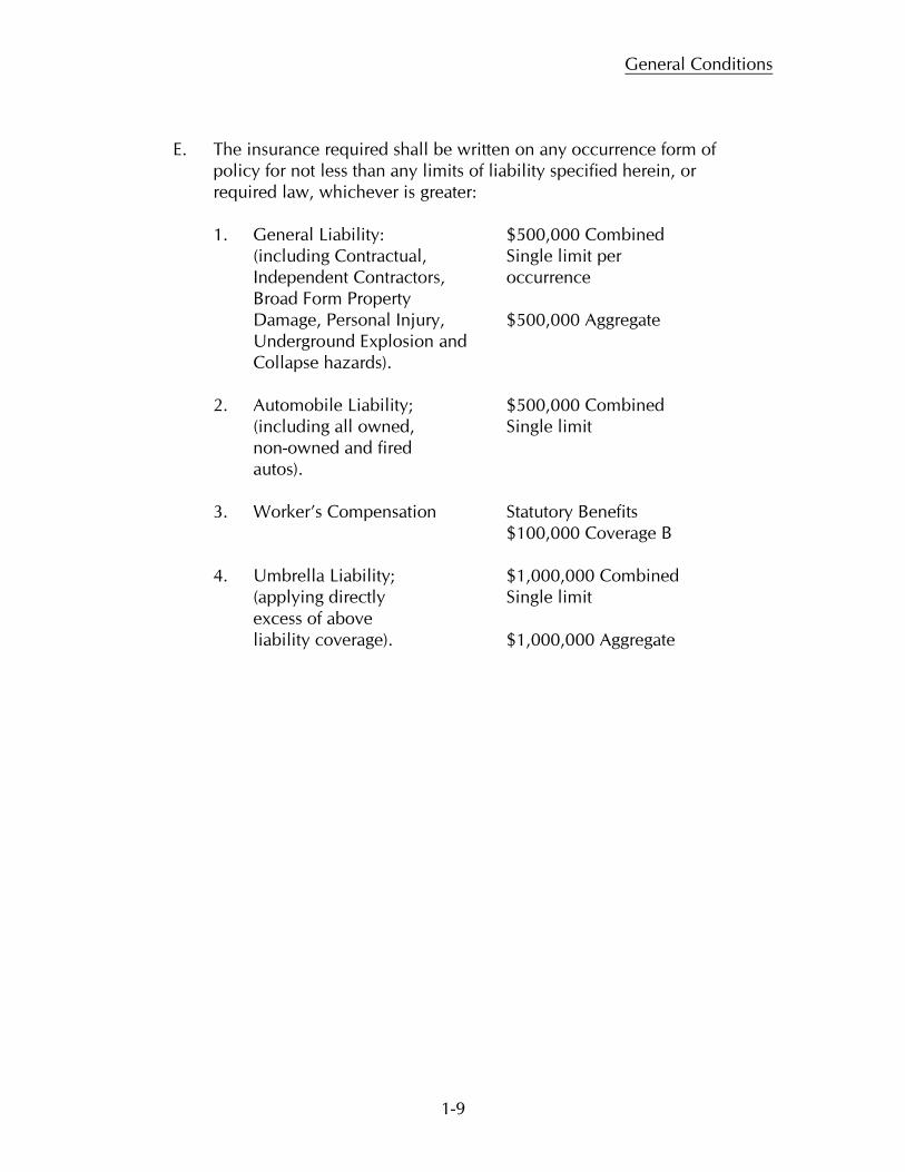
E. The insurance required shall be written on any occurrence form of
policy for not less than any limits of liability specified herein, or required law, whichever is greater: 1. General Liability: $500,000 Combined (including Contractual, Single limit per Independent Contractors, occurrence Broad Form Property Damage, Personal Injury, $500,000 Aggregate Underground Explosion and Collapse hazards). 2. Automobile Liability; $500,000 Combined (including all owned, Single limit non-owned and fired autos). 3. Worker’s Compensation Statutory Benefits $100,000 Coverage B 4. Umbrella Liability; $1,000,000 Combined (applying directly Single limit excess of above liability coverage). $1,000,000 Aggregate
2-1
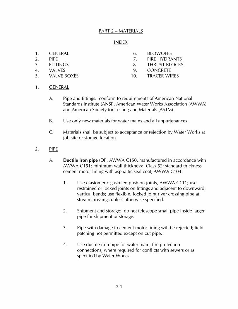
PART 2 – MATERIALS
1. GENERAL 6. BLOWOFFS 2. PIPE 7. FIRE HYDRANTS 3. FITTINGS 8. THRUST BLOCKS 4. VALVES 9. CONCRETE 5. VALVE BOXES 10. TRACER WIRES
INDEX
1. A. Pipe and fittings: conform to requirements of American National Standards Institute (ANSI), American Water Works Association (AWWA) and American Society for Testing and Materials (ASTM). B. Use only new materials for water mains and all appurtenances. C. Materials shall be subject to acceptance or rejection by Water Works at job site or storage location.
GENERAL
2. A. Ductile iron pipe (DI): AWWA C150, manufactured in accordance with AWWA C151; minimum wall thickness: Class 52; standard thickness cement-motor lining with asphaltic seal coat, AWWA C104. 1. Use elastomeric gasketed push-on joints, AWWA C111; use
restrained or locked joints on fittings and adjacent to downward, vertical bends; use flexible, locked joint river crossing pipe at stream crossings unless otherwise specified.
2. Shipment and storage: do not telescope small pipe inside larger pipe for shipment or storage.
3. Pipe with damage to cement motor lining will be rejected; field patching not permitted except on cut pipe.
4. Use ductile iron pipe for water main, fire protection connections, where required for conflicts with sewers or as specified by Water Works.
PIPE
Materials
2-2
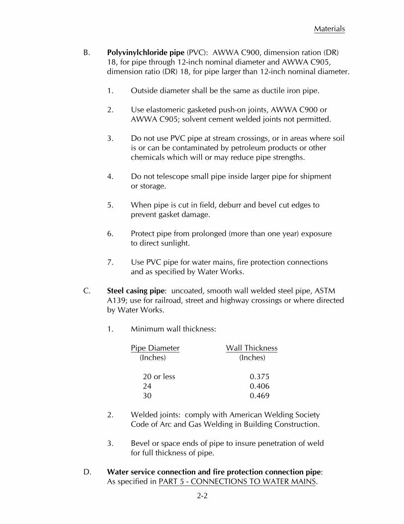
B. Polyvinylchloride pipe (PVC): AWWA C900, dimension ration (DR) 18, for pipe through 12-inch nominal diameter and AWWA C905,
dimension ratio (DR) 18, for pipe larger than 12-inch nominal diameter.
1. Outside diameter shall be the same as ductile iron pipe. 2. Use elastomeric gasketed push-on joints, AWWA C900 or AWWA C905; solvent cement welded joints not permitted.
3. Do not use PVC pipe at stream crossings, or in areas where soil is or can be contaminated by petroleum products or other chemicals which will or may reduce pipe strengths.
4. Do not telescope small pipe inside larger pipe for shipment or storage. 5. When pipe is cut in field, deburr and bevel cut edges to prevent gasket damage. 6. Protect pipe from prolonged (more than one year) exposure to direct sunlight. 7. Use PVC pipe for water mains, fire protection connections and as specified by Water Works. C. Steel casing pipe: uncoated, smooth wall welded steel pipe, ASTM
A139; use for railroad, street and highway crossings or where directed by Water Works.
1. Minimum wall thickness: Pipe Diameter (Inches) (Inches)
Wall Thickness
20 or less 0.375 24 0.406 30 0.469 2. Welded joints: comply with American Welding Society Code of Arc and Gas Welding in Building Construction. 3. Bevel or space ends of pipe to insure penetration of weld for full thickness of pipe.
D. Water service connection and fire protection connection pipe: As specified in PART 5 - CONNECTIONS TO WATER MAINS.
Materials
2-3
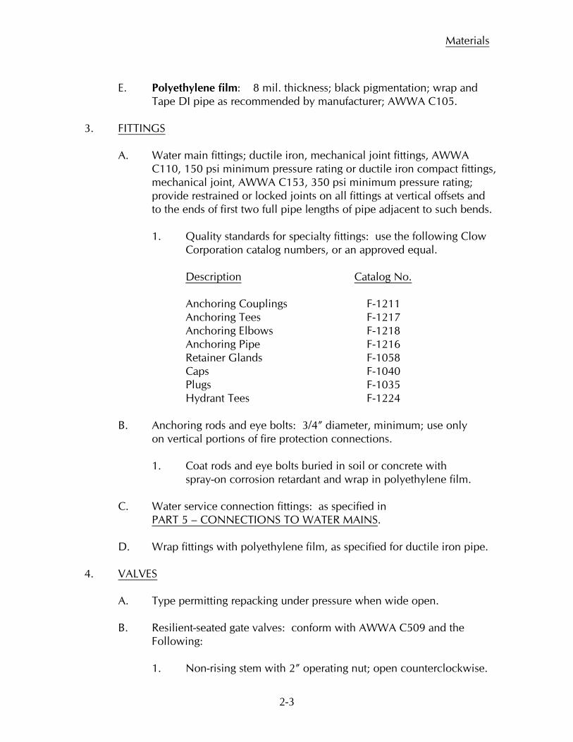
E. Polyethylene film: 8 mil. thickness; black pigmentation; wrap and Tape DI pipe as recommended by manufacturer; AWWA C105. 3. FITTINGS
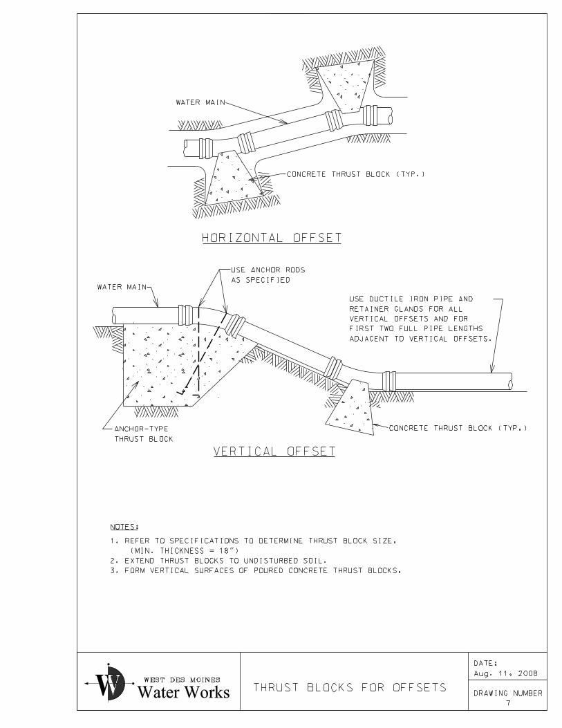
A. Water main fittings; ductile iron, mechanical joint fittings, AWWA C110, 150 psi minimum pressure rating or ductile iron compact fittings, mechanical joint, AWWA C153, 350 psi minimum pressure rating; provide restrained or locked joints on all fittings at vertical offsets and to the ends of first two full pipe lengths of pipe adjacent to such bends.
1. Quality standards for specialty fittings: use the following Clow Corporation catalog numbers, or an approved equal. Description
Catalog No.
Anchoring Couplings F-1211 Anchoring Tees F-1217 Anchoring Elbows F-1218 Anchoring Pipe F-1216 Retainer Glands F-1058 Caps F-1040 Plugs F-1035 Hydrant Tees F-1224 B. Anchoring rods and eye bolts: 3/4” diameter, minimum; use only on vertical portions of fire protection connections. 1. Coat rods and eye bolts buried in soil or concrete with spray-on corrosion retardant and wrap in polyethylene film. C. Water service connection fittings: as specified in
PART 5 – CONNECTIONS TO WATER MAINS
.
D. Wrap fittings with polyethylene film, as specified for ductile iron pipe. 4.
VALVES
A. Type permitting repacking under pressure when wide open. B. Resilient-seated gate valves: conform with AWWA C509 and the Following: 1. Non-rising stem with 2” operating nut; open counterclockwise.
Materials
2-4
2. Ductile iron valve body, ATSM A536; urethane or nitrile rubber coated ductile iron disk; bronze trim, mechanical joint or push-on ends. 3. Approved valves: Clow Corporation F-6100 and F-6110,
Waterous Company AFC-2500 and Mueller Company A2370-20 or approved equal.
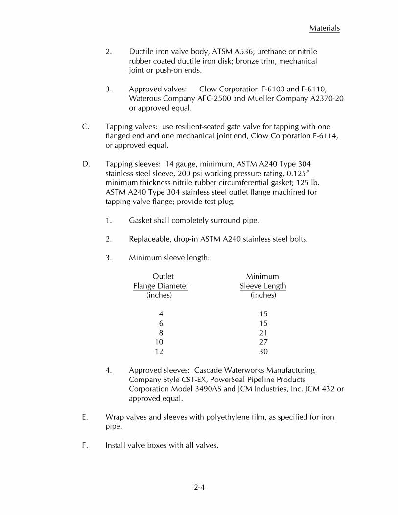
C. Tapping valves: use resilient-seated gate valve for tapping with one flanged end and one mechanical joint end, Clow Corporation F-6114, or approved equal. D. Tapping sleeves: 14 gauge, minimum, ASTM A240 Type 304 stainless steel sleeve, 200 psi working pressure rating, 0.125” minimum thickness nitrile rubber circumferential gasket; 125 lb. ASTM A240 Type 304 stainless steel outlet flange machined for tapping valve flange; provide test plug. 1. Gasket shall completely surround pipe. 2. Replaceable, drop-in ASTM A240 stainless steel bolts. 3. Minimum sleeve length: Outlet Minimum Flange Diameter Sleeve Length (inches) (inches)
4 15 6 15 8 21 10 27 12 30 4. Approved sleeves: Cascade Waterworks Manufacturing Company Style CST-EX, PowerSeal Pipeline Products
Corporation Model 3490AS and JCM Industries, Inc. JCM 432 or approved equal.
E. Wrap valves and sleeves with polyethylene film, as specified for iron
pipe. F. Install valve boxes with all valves.
Materials
2-5
5.
VALVE BOXES
A. Clow Corporation F-2450, screw-type valve box F-2490 drop cover, or approved equal.
1. Use trench adaptor in paved areas; use screw-type valve box elsewhere. 6.
BLOWOFFS
A. Blow-off hydrant required at all dead-end pipe locations, regardless of whether the water main may be extended in the future.
7.
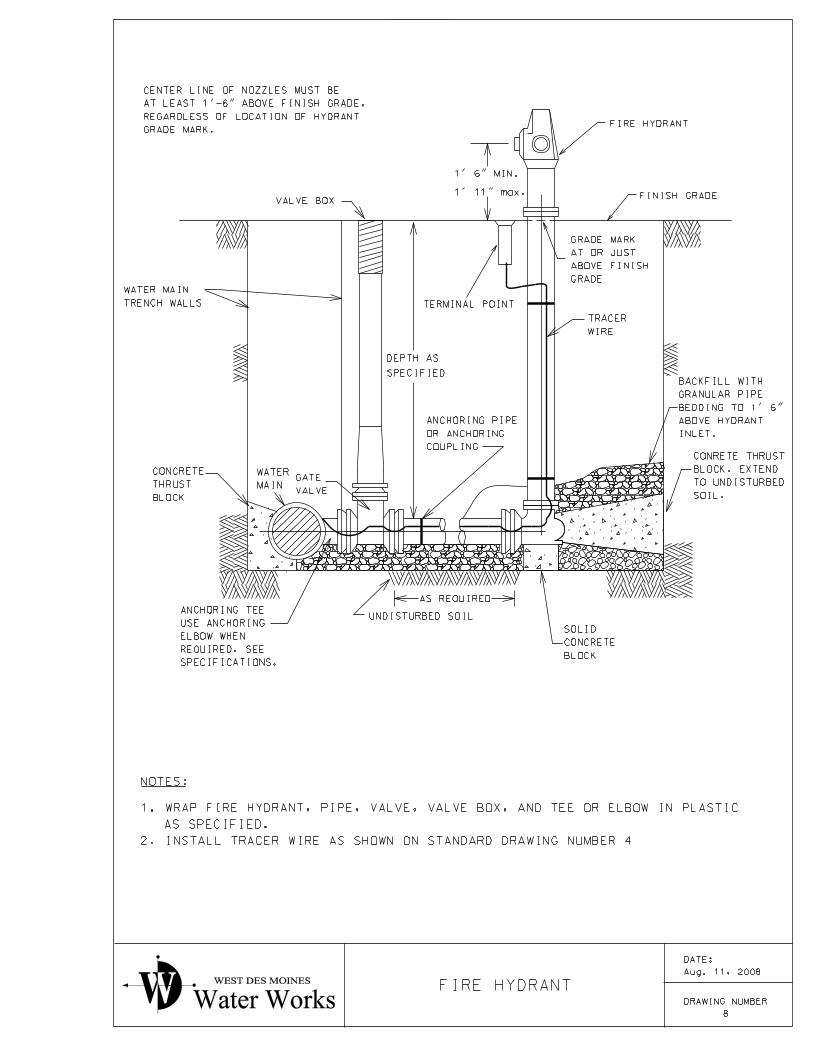
FIRE HYDRANTS
A. Conform with AWWA C502 and the following: 1. Six inch diameter side inlet, break flange dry barrel fire hydrants, constructed primarily of ductile iron and highest grade bronze customarily used by manufacturer; oil lubricated top, center stem with Buna-N O-ring seals; allow full circle rotation of nozzle section; depth of bury to match depth of cover for water main. 2. Two 2-1/2 inch diameter hose nozzles and one 4-1/2 inch diameter pumper nozzle with National Standard threads, caps and rubber gaskets; no cap chains. 3. Provide 6 inch diameter mechanical joint inlet and 5-1/4
inch diameter bronze to rubber main valve, with integral bronze drain valve; designs using separate operating rods for drain valves not acceptable; open main valve counterclockwise.
4. Pentagon shaped, 1-1/2 inch point to flat operating nut.
5. Auxiliary valve and valve box: use resilient-seated gate valve and valve box specified hereinbefore.
6. Approved fire hydrants: Waterous Company Model WB-67-90 Pacer, Clow Corporation Medallion and Mueller Company Super Centurion 200.
B. Install fire hydrants per standard drawing using anchoring, standard or
hydrant tee, anchoring pipe or coupling and other appurtenances as required.
Materials
2-6
1. Standard tee and anchoring elbow may be used in lieu of hydrant tee. 2. Place center of lowest nozzle(s) at least 1’-6” above grade;
install extensions whenever specified fire hydrant length will place nozzle(s) less than 1’-6” above grade.
3. Ensure that break flange and break coupling are at joint between barrel and nozzle section when extensions are installed.
4. Only 1 extension allowed per hydrant unless otherwise approved by Water Works.
C. Coat interior and exterior of fire hydrants, except exterior above grade
mark, with two coats of asphalt varnish; finish exterior of hydrant above grade mark as specified herein.
1. Thoroughly clean in accordance with Steel Structures Painting
Council Specification SP8 (Pickling) and prime with Tnemec 10-99 or 10-99W Alkyd Rust-inhibitive Primer and two coats of 02SF Series 2H Tnemec-Gloss Alkyd Enamel; color: Safety Yellow.
2. Other paints may be used provided if fully compatible with paint
specified herein and are approved by Water Works. 3. Provide two copies of literature showing compliance with these
paint and surface preparation specification. D. After hydrant is installed and is ready for use:
1. Touch up paint as necessary to cover paint damaged during installation.
2. Paints may be purchased from Water Works.
E. Wrap fire hydrants with polyethylene film, as specified for ductile iron pipe.
F. Install fire hydrants with auxiliary valves and valve boxes. 8
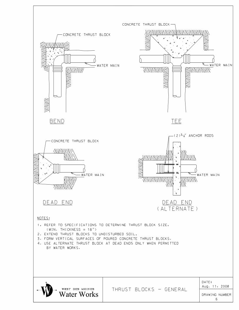
THRUST BLOCKS
A. Provide concrete thrust blocks at all fittings and at dead ends.
Materials
2-7
B. Extend thrust block to undisturbed edge of trench, but provide minimum thickness of 1’-6”.
1. Does not apply to anchor-type thrust blocks. C. Refer to Standard Drawings for general arrangement of thrust blocks;
place plastic film between fittings and thrust block; do not plug end of fitting with concrete.
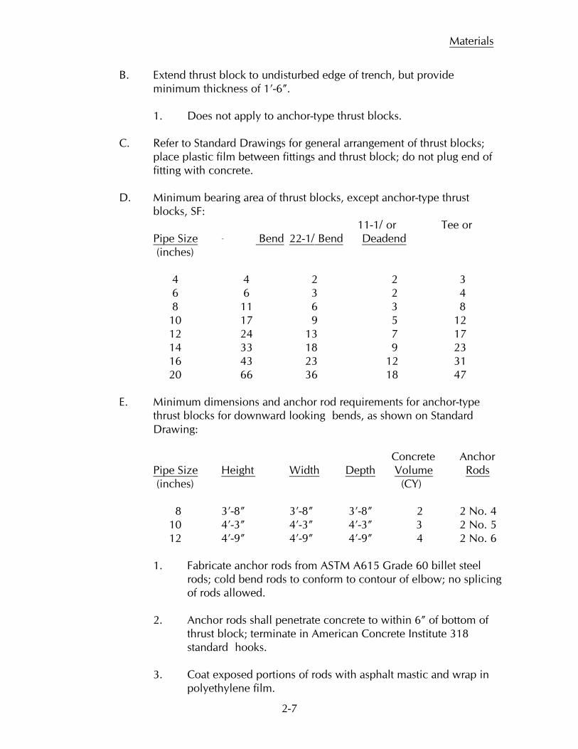
D. Minimum bearing area of thrust blocks, except anchor-type thrust
blocks, SF: 11-1/
or Tee or Pipe Size Bend 22-1/ Bend
(inches) Deadend
4 4 2 2 3 6 6 3 2 4 8 11 6 3 8 10 17 9 5 12 12 24 13 7 17 14 33 18 9 23 16 43 23 12 31 20 66 36 18 47 E. Minimum dimensions and anchor rod requirements for anchor-type
thrust blocks for downward looking
bends, as shown on Standard Drawing:
Concrete Anchor Pipe Size Height Width Depth Volume Rods (inches) (CY)
8 3’-8” 3’-8” 3’-8” 2 2 No. 4 10 4’-3” 4’-3” 4’-3” 3 2 No. 5 12 4’-9” 4’-9” 4’-9” 4 2 No. 6
1. Fabricate anchor rods from ASTM A615 Grade 60 billet steel rods; cold bend rods to conform to contour of elbow; no splicing of rods allowed.
2. Anchor rods shall penetrate concrete to within 6” of bottom of
thrust block; terminate in American Concrete Institute 318 standard
hooks.
3. Coat exposed portions of rods with asphalt mastic and wrap in polyethylene film.

Materials
2-8
4. Construct anchor-type thrust blocks and install anchor rods as
shown on Standard Drawing. 9.
CONCRETE
A. Concrete materials: 1. Portland cement: ASTM C150, Type I.
2. Aggregates: strong, durable, uniformly graded crushed limestone, size 1” to No. 4 sieve; conform with ASTM C33.
B. Concrete quality: 1. Minimum compressive strength at 28 days: 3,500 psi. 2. Maximum water-cement ratio, including water in aggregates: 5-1/2 gallons per sack. 3. Minimum cement content: 5-1/2 sacks per cubic yard. 10.
TRACER WIRE
A. Use tracer wire with all pipe: Direct burial #12 AWG solid (.0808” diameter) steel core hard drawn extra high strength directional drill tracer wire, 1150# average tensile break load, 45 mil high molecular weight-high density yellow polyethylene jacket complying with ASTM-D-1248, 30 volt rating.
1. Install tracer wire as shown on Standard Drawing.
B. Splices: use 3M buried splice kit, either epoxy or silicone. C. Terminal point: supplied at no cost by Water Works for installation by Contractor. D. Ground rod: Copperweld, or equal, install as shown on Standard Drawing.
3-1
PART 3 – EXCAVATION AND BACKFILL
INDEX
1. GENERAL 6. DIRECTIONAL DRILLING 2. EXCAVATION FOR STRUCTURES 7. DEWATERING 3. TRENCH EXCAVATION 8. BACKFILL FOR STRUCTURES 4. ROCK AND RUBBLE EXCAVATION 9. TRENCH BACKFILL 5. SHEETING, SHORING AND 10. SURFACE RESTORATION BRACING 11. CONCRETE ENCASEMENT 1. GENERAL A. Excavate in open cut except when tunneling is required by Water Works; see PART 1 – GENERAL CONDITIONS. B. Protect all existing pavement, sidewalks and driveways from damage during construction; if damage occurs, restore surface at no expense to Water Works, City or private property owners.
C. Reference to percent maximum density shall mean a soil density not less than the stated percent of maximum density for soil as determined by ASTM D698 Moisture-Density Relations of Soils Using 5.5 lb Rammer and 12” Drop. (Standard Proctor Method)
D. Contractor is reminded that Occupational Safety and Health Administration (OSHA) Part 1926, Subpart P - Excavations, as adopted by
the Iowa Department of Labor, applies to work in this part of the Specifications.
2. EXCAVATION FOR STRUCTURES A. Includes excavation for all structures.
B. Excavate as required to firm, undisturbed soil; if excavation is carried below bottom of structure foundation, fill with stabilizing material as specified herein.
C. Provide sheeting. shoring and bracing where required to hold walls of
excavation, to protect existing structures or utilities or to provide safety for workers.
Excavation and Backfill
3-2
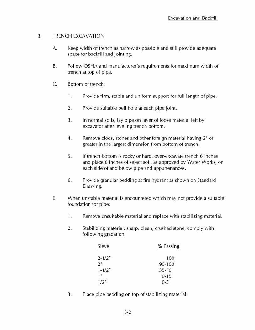
3. TRENCH EXCAVATION A. Keep width of trench as narrow as possible and still provide adequate space for backfill and jointing.
B. Follow OSHA and manufacturer’s requirements for maximum width of trench at top of pipe.
C. Bottom of trench: 1. Provide firm, stable and uniform support for full length of pipe. 2. Provide suitable bell hole at each pipe joint.
3. In normal soils, lay pipe on layer of loose material left by excavator after leveling trench bottom.
4. Remove clods, stones and other foreign material having 2” or
greater in the largest dimension from bottom of trench. 5. If trench bottom is rocky or hard, over-excavate trench 6 inches
and place 6 inches of select soil, as approved by Water Works, on each side of and below pipe and appurtenances.
6. Provide granular bedding at fire hydrant as shown on Standard
Drawing.
E. When unstable material is encountered which may not provide a suitable foundation for pipe:
1. Remove unsuitable material and replace with stabilizing material. 2. Stabilizing material: sharp, clean, crushed stone; comply with
following gradation: Sieve % Passing 2-1/2” 100 2” 90-100 1-1/2” 35-70 1” 0-15 1/2” 0-5 3. Place pipe bedding on top of stabilizing material.
Excavation and Backfill
3-3
a. Pipe bedding: sharp, clean, crushed stone; comply with following gradation: Sieve % Passing 1” 100 3/4” 80-95 1/2” 50-60 3/8” 20-40 No. 4 0-5
F. Excavate trench as required to permit tapping of water main by Water
Works and installation of water service pipe by others. 1. See PART 5 – CONNECTIONS TO WATER MAINS for trench and shoring requirements for connections to water mains.
4. ROCK AND RUBBLE EXCAVATION
A. If trench bottom is extremely hard or is in rock or rubble where there is a possibility of pipe being subjected to point contact: 1. Overexcavate trench bottom 6”, minimum, below grade. 2. Backfill overexcavation with pipe bedding material; place pipe
bedding material as shown on Standard Drawing.
B. Use of explosives shall not be permitted. C. Dispose of excavated rock and rubble not suitable for backfill. 5. SHEETING, SHORING AND BRACING
A. Construct sheeting, shoring and bracing where required to hold walls of excavation, to provide safety for workers, or protect existing utilities or structures or to permit construction in the dry.
B. Leave sheeting and shoring in place 2’ over top of pipe when removal
might damage new pipe, existing utilities or structures. C. Provide temporary support or existing water, gas, telephone, power and
other utility services that cross trench until backfilling of the trench has been completed; do not use support methods which transfer weight or forces to other utilities. Compact backfill under existing utility crossing to 95% maximum density.
Excavation and Backfill
3-4
6. DIRECTIONAL DRILLING
A. Directional drilling may be required under street pavement, as specified in PART 1 – GENERAL CONDITIONS.
1. Water main must be installed in casing pipe under railroads and
highways.
B. Obtain approval of Water Works and Railroad or Iowa DOT on method before starting; auger or jack pipe in place.
C. If pipe is augured, clean out pipe upon completion of operation. D. If pipe is jacked, clean out pipe as work progresses; use dry bore method.
E. Maintain correct vertical and horizontal alignment by using centering
chalks.
F. Maintain street, highway or railroad for full use by traffic at all times. Water Works may give permission to close one or more lanes of traffic, when possible.
G. Where directional drilling is used below or adjacent to structures or under paved surfaces Contractor is responsible to use necessary methods and care to prevent settlement of structures or surfaces.
7. DEWATERING
A. Do all work in the dry; provide for handling water encountered during construction.
B. Lay no pipe or pour no concrete on excessively wet soil. C. Prevent surface water from flowing into excavation; remove water as it
accumulates. D. Divert stream flow away from areas of construction. E. Do not pump water onto adjacent property without approval of property
owner. Do not use sanitary sewers for disposal of trench water. F. Abide by all EPA and IDNR regulations.
Excavation and Backfill
3-5
8. BACKFILL FOR STRUCTURES A. Backfill after concrete or masonry has cured.
B. Backfill with suitable material removed from excavation except where other backfill is specified; use no debris, frozen earth, large clods or stones.
C. Backfill simultaneously on all sides of structure; save structure from
damage at all times. D. Compact backfill at structures to density not less than that specified for
adjacent trench. 9. TRENCH BACKFILL
A. Backfill trench for water main and fire protection connections immediately after location of connections and appurtenances have been recorded and Water Works has inspected the work.
B. Backfill trench for water service connections after location of connection
has been recorded and after Water Works has inspected the work. C. Backfill with suitable excavated material or borrow materials. Use no
large stones, large clods, organic matter, rubbish or frozen material. D. Hand place and compact suitable excavated material adjacent to pipe
and to 1 foot over top of pipe. Backfill simultaneously on both sides of pipe. Compact as specified for other portions of trench.
E. Trenches under streets, driveways and parking areas:
1. Backfill above 1’ over top of pipe with excavated material in lifts of approximately 1’; compact to 95% maximum density at moisture content between -2% and +3% of optimum.
2. Replace surfacing material as specified hereinafter. F. All other trenches:
1. Backfill above 1’ over top of pipe with excavated material in lifts of approximately 1’; compact to 95% maximum density at moisture content between -2% and +3% of optimum.
Excavation and Backfill
3-6
2. Fill upper portion of trench with topsoil; provide minimum 1’ topsoil layer for all trenches.
G. Compaction method: Contractor’s choice; moisture – density
specifications must be met throughout length and depth of excavated area. Hydraulic compaction or water jetting of pipe trenches shall not be permitted.
H. New water main below existing water main, sewer or gas main: backfill under existing water main, sewer or gas main with granular
backfill; compact to 95% maximum density; length of backfill at elevation of existing utility equal to depth of excavation below utility.
I. If removal of sheeting disturbs compacted backfill, recompact backfill to
comply with specifications.
J. Water Works will retain independent testing laboratory to conduct moisture-density compaction tests to ensure conformance with compaction requirement.
1. Two compaction tests will be conducted for each hard surface
area or street crossing, where open cut construction was used; trench depths at which tests are conducted will be determined by Water Works; Contractor shall dig holes for tests.
2. One compaction test will be conducted for each 150’ of trench in
other locations; trench depths at which tests are conducted will be determined by Water Works; Contractor shall dig holes for tests.
3. Water Works may increase rate of testing if soil conditions or Contactor operations indicate specified soil moisture and density is not being consistently obtained.
K. If settlement of any trench occurs within period of guarantee and bond;
core, refill, compact, level off and restore surfacing as directed by Water Works.
10. SURFACE RESTORATION A. Surface restoration will be required as shown on plans.
B. Work included: sidewalk, driveway and street surface replacement and seeding or sodding.
Excavation and Backfill
3-7
C. Detailed specifications for this work are set out in the current edition of “Standard Construction Specifications for Subdivisions” of the City of West Des Moines.
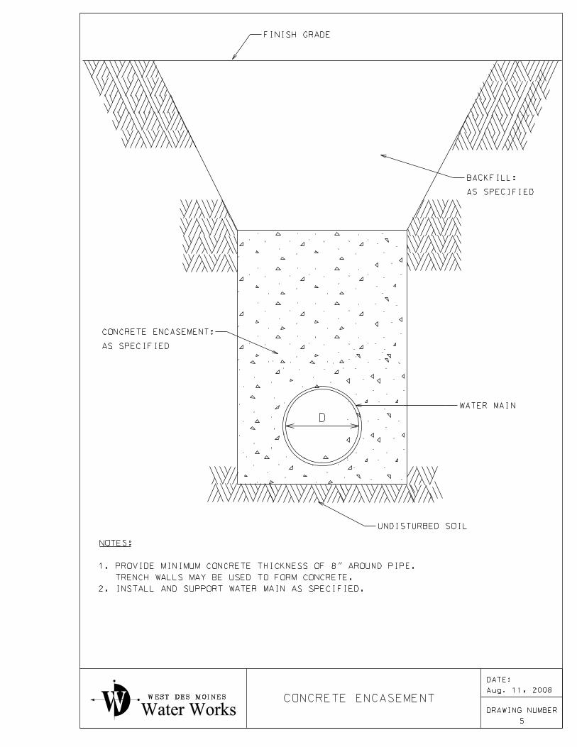
11. CONCRETE ENCASEMENT
A. Place concrete encasement where shown on plans or where directed by Water Works.
1. Make pipe joint in same manner as specified for pipe not encased. 2. Pour concrete beneath and around pipe after jointing is complete. 3. Use two temporary pipe supports per pipe length; one near bell
and one near spigot. 4. Provide ties and braces to prevent displacement or flotation during
encasement. B. Construct concrete encasement as shown on Standard Drawing.
4 -1
PART 4 – INSTALLATION
INDEX
1. PIPE 5. STREET CROSSINGS 2. VALVES 6. TESTS 3. FIRE HYDRANT 7. DISINFECTION 4. RAILROAD AND HIGHWAY CROSSINGS 1.
PIPE
A. Lay pipe in the dry; 5’ minimum earth cover over top of pipe, except 7’ minimum earth cover over top of pipe at stream crossings; other depths of cover may be required by Water Works to accommodate future grading plans.
1. Install water main and appurtenances in accordance with
AWWA C600 and C900. 2. Water main should normally be located 4’ back of curb line of
existing or proposed pavement as shown on Standard Drawing. 3. Make pipe joints in accordance with AWWA C600 and C900
and as recommended by manufacturer; use minimum amount of gasket lubricant; apply to gasket only; do not apply lubricant to inside of bell.
B. Clean pipe interior of foreign material before lowering into trench; keep
clean at all times; when pipe laying is not in progress, including lunch breaks, nights, weekends and other non-working periods, securely close open ends of pipe and fittings with watertight plugs.
C. Place in trench in sound, undamaged condition; do not damage pipe
coating or lining; use web slings to install or move pipe; use of end hooks and dropping pipe are prohibited.
1. Hand excavate under polyvinylchloride pipe, as required, to
provide uniform bearing and support for full length of pipe barrel against undisturbed earth; ensure that pipe is properly supported before backfilling begins.
2. Do not apply heat to polyvinylchloride pipe.
Installation
4 -2
3. Install tracer wire along pipe; bring wire to ground surface at fire hydrants, valves and blowoffs.
4. Wrap iron pipe and fittings with polyethylene film; AWWA
C105.
D. Cut pipe in neat and workmanlike manner without damage to pipe; bevel cut ends of pipe.
1. Completely coat damaged ends of ductile iron with bituminous
sealer; use spray-on type sealer which will adhere to liner at any temperature; do not install pipe or fittings showing blisters or holes.
E. Before installation of ductile iron pipe, tap pipe lightly with light
hammer to detect cracks; visually inspect pipe lining for defects; do not install defective, damaged or unsound pipe.
F. Before installation of polyvinylchloride pipe, inspect pipe visually
inside and outside for defects; do not install defective, damaged or unsound pipe.
G. Deflect ductile iron pipe joints as required in accordance with
recommendations of pipe manufacturer or
per joint, whichever is less; use suitable fittings for larger deflections in alignment or grade. Use fittings as necessary along curved streets to locate water main minimum of 4’ from back of curb.
H. Deflect polyvinylchloride pipe joints as required in accordance with recommendations of pipe manufacturer or 1½o
per joint, whichever is less; use suitable fittings for larger deflections in alignment or grade. Use fittings as necessary along curved streets to locate water main minimum of 4’ from back of curb.
I. Water mains shall be separated from gravity sewers by a horizontal distance of at least 10’, unless the top of a sewer main is at least 18” below the bottom of the water main and the sewer is placed in a separate trench or in the same trench on a bench of undisturbed earth at a minimum horizontal separation of 3 feet from the water main.
1. If above separations cannot be achieved, replace sewer with
ductile iron pipe as specified in PART 2 – MATERIALS
. A linear separation of at least 2 feet shall be provided.
J. Water mains shall be separated from sewer force mains by a horizontal distance of at least 10’ unless force main is constructed of water main
Installation
4 -3
materials specified in PART 2 – MATERIALS
; a minimum horizontal separation of 4’ must be maintained.
K. Vertical separation of water mains crossing over any sanitary sewer should be at least 1’-6” when measured from bottom of water main to top of sewer. A minimum separation of 6” shall be maintained if water
main is over sewer or 1’-6” if water main is under sewer. Separation distance shall be maximum possible in all cases.
1. One full length of water main pipe shall be centered at sewer
crossing. Water main and sewer shall be adequately supported and have watertight joints. Use low permeability soil for backfill within 10 feet of point of crossing.
L. Water mains shall be separated from sewer manholes by a horizontal
distance of at least 3’. M. Exceptions to paragraph G through L may be considered in areas where
one of the pipes or structures exists prior to proposed construction; no exceptions will be granted in areas where both facilities are to be constructed at present time.
1. Exceptions must be approved prior to construction, in writing,
by the Water Works.
N. Plug or cap all pipe ends or fittings left for future connections; construct concrete thrust blocks as shown on Standard Drawing.
O. Construct concrete thrust blocks at all fittings, at dead ends and at
alternate pipe joints where pipe joints are deflected to accommodate small changes in pipe direction.
P. Construct thrust blocks as specified in PART 2 – MATERIALS
.
Q. When making connections to existing piping, install one repair sleeve on each side of connection. 1. Do not deflect pipe or apply force to existing piping. 2. Do not force pipe, pipe joints or appurtenances in place. 3. Cut and remove existing piping as necessary; install new
appurtenances and piping to exact length with minimum clearances between pipe ends at repair sleeves.
Installation
4 -4
2.
VALVES
A. Install valve with stem vertical and centered in box, support as required.
1. Wrap valves with polyethylene film, AWWA C105. B. Check all valve bolts when valve is installed; tighten as necessary after
water main is at operating pressure. C. Carefully tamp soil around each valve box to distance of 4’ on all sides
or to undisturbed trench face if less than 4’. D. Ensure that valves and sidewalks do not conflict; move valves which
conflict with normal alignment of sidewalks. 3.
FIRE HYDRANTS
A. Install fire hydrant plumb; set at elevation so that cover over fire hydrant lead pipe will not be less than that provided for adjacent water main; set grade mark on fire hydrant barrel at finish grade; provide extension as required; install fire hydrant as shown on Standard Drawing.
1. Wrap fire hydrants with polyethylene film; AWWA C105.
2. All pipe and fittings associated with fire hydrant installation: 6” diameter, minimum.
B. Carefully tamp backfill around fire hydrant to a distance of 4’ on all
sides of fire hydrant or to undisturbed trench face, if less than 4’. C. Operate fire hydrant from open to closed positions to ensure all parts
are in working condition; block fire hydrant in place. D. Install fire hydrants as shown on Standard Drawing, except when street right-of-way is 50’ or less in width, provide
anchoring elbow.
E. Ensure that fire hydrants and sidewalks do not conflict; move fire hydrants which conflict with normal alignment of sidewalks.
4.
RAILROAD AND HIGHWAY CROSSINGS
A. Install railroad and highway crossings as specified in PART 1 – GENERAL CONDITIONS
.
Installation
4 -5
5.
STREET CROSSINGS
A. Install street crossings as specified in PART 1 – GENERAL CONDITIONS
.
6.
TESTS
A. Water test all piping in accordance with AWWA C600 after installation is complete.
B. Pressure and leakage test:
1. Provide test pumps, test plugs, pipe and gauges necessary and make connections required for tests.
2. Flush water main before test to remove air and construction
debris; insert taps to release trapped air; flush at water flow rate which will provide approximately 2.5 feet per second velocity in water main.
3. Quantity of water used for flushing will be measured by Water
Works; Water Works will provide water without charge for flushing for first four changes of water main contents; additional water will be billed to Contractor at prevailing rates.
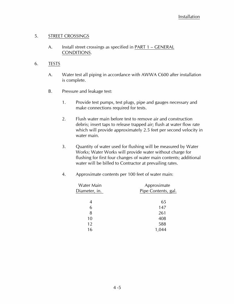
4. Approximate contents per 100 feet of water main: Water Main Approximate Diameter, in.
Pipe Contents, gal.
4 65 6 147 8 261 10 408 12 588 16 1,044
Installation
4 -6
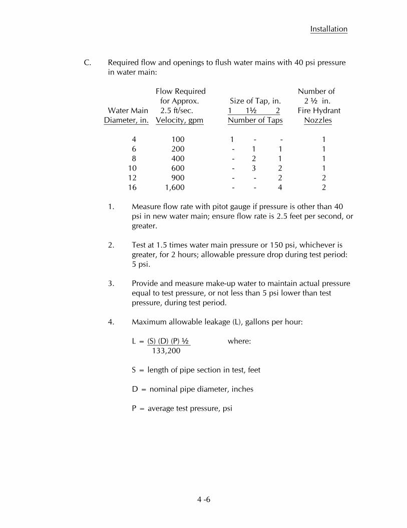
C. Required flow and openings to flush water mains with 40 psi pressure
in water main: Flow Required Number of for Approx. Size of Tap, in. 2 ½ in.
Water Main 2.5 ft/sec. 1 1½ 2
Fire Hydrant Diameter, in. Velocity, gpm Number of Taps
Nozzles
4 100 1 - - 1 6 200 - 1 1 1 8 400 - 2 1 1 10 600 - 3 2 1 12 900 - - 2 2 16 1,600 - - 4 2
1. Measure flow rate with pitot gauge if pressure is other than 40 psi in new water main; ensure flow rate is 2.5 feet per second, or greater.
2. Test at 1.5 times water main pressure or 150 psi, whichever is
greater, for 2 hours; allowable pressure drop during test period: 5 psi.
3. Provide and measure make-up water to maintain actual pressure
equal to test pressure, or not less than 5 psi lower than test pressure, during test period.
4. Maximum allowable leakage (L), gallons per hour: L = (S) (D) (P) ½ 133,200
where:
S = length of pipe section in test, feet D = nominal pipe diameter, inches P = average test pressure, psi
Installation
4 -7
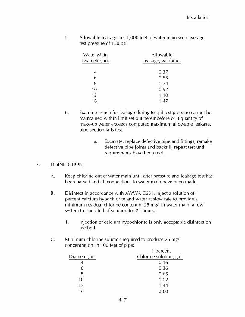
5. Allowable leakage per 1,000 feet of water main with average test pressure of 150 psi: Water Main Allowable Diameter, in.
Leakage, gal./hour.
4 0.37 6 0.55 8 0.74 10 0.92 12 1.10 16 1.47 6. Examine trench for leakage during test; if test pressure cannot be
maintained within limit set out hereinbefore or if quantity of make-up water exceeds computed maximum allowable leakage, pipe section fails test.
a. Excavate, replace defective pipe and fittings, remake
defective pipe joints and backfill; repeat test until requirements have been met.
7.
DISINFECTION
A. Keep chlorine out of water main until after pressure and leakage test has been passed and all connections to water main have been made.
B. Disinfect in accordance with AWWA C651; inject a solution of 1
percent calcium hypochlorite and water at slow rate to provide a minimum residual chlorine content of 25 mg/l in water main; allow system to stand full of solution for 24 hours.
1. Injection of calcium hypochlorite is only acceptable disinfection
method. C. Minimum chlorine solution required to produce 25 mg/l concentration in 100 feet of pipe: 1 percent Diameter, in. 4 0.16
Chlorine solution, gal.
6 0.36 8 0.65 10 1.02 12 1.44 16 2.60
Installation
4 -8
D. Minimum chlorine residual at pipe extremities: 10 mg/l at end of test period; if requirement is not met, repeat disinfection procedure. E. Operate valves, under supervision of Water Works, in new water main
to ensure full disinfection; ensure no highly chlorinated water enters water mains already in service.
F. Flush water main after test until extremities indicate same chlorine
residual as supply water. 1. Quantity of water used for flushing will be measured by Water
Works; Water Works will provide water without charge for flushing for first two changes of water main contents; additional water will be billed to Contractor at prevailing rates.
G. Twenty-four hours after completion of disinfection, Water Works will
collect bacteria samples at representative locations along new water mains.
1. Two consecutive sets of acceptable bacteria samples collected
24 hours apart must be collected from the new water main prior to being placed into service.
5-1
PART 5 – CONNECTIONS TO WATER MAINS
INDEX
1. GENERAL 4. WORK BY OTHERS 2. MATERIALS 5. INSPECTION OF WORK 3. WORK BY WATER WORKS BY OTHERS 1.
GENERAL
A. This part of the specifications sets out Water Works requirements for water service connections and fire protection connections conveying unmetered water.
B. Definitions:
1. “Water service connections” shall mean the pipe and appurtenances extending from a public or private water main, or a fire protection connections, to a building and conveying water for all uses, except fire protection.
2. “Fire protection connection” shall mean the pipe and
appurtenances extending from a public or private water main to a building and conveying water for fire protection purposes.
C. Water Works standard tap diameters: 1 inch, 1-1/2 inch, 2 inch, 4 inch,
6 inch, 8 inch, 10 inch and 12 inch. 1. Make own arrangements for taps larger than 12 inch diameter;
obtain Water Works approval of method prior to beginning work.
D. Water service connection saddles, as specified herein, are required for
all taps, regardless of water main diameter.
E. Install residential curb valve and curb valve box 6’-0” inside public right-of-way line when public water main is located in street right-of-way; ensure curb valve will not be located in a sidewalk. 1. Install curb valves for commercial buildings a minimum 5’
outside of building.
F. Cross connection control may be required; conform to City of West Des Moines Ordinance 1015.
Connections to Water Mains
5-2
G. Depth of cover for fire protection connections: as specified for water mains.
H. Depth of cover for water service connections: 5’-0”, minimum, except
for short “gooseneck” section next to water main, where depth of cover shall not be less than 4’-6”.
I. Install connections to water mains after pressure and leakage tests have
been passed, but prior to chlorination of water mains. 2. MATERIALS A. Corporation valves for l inch, 1-1/2 inch and 2 inch diameter taps:
AWWA standard inlet with compression-type outlet for Type K copper tubing; Ford FB 1000, or approved equal.
B. Water service connection saddles: Nylon coated ductile iron body,
acid resistant gasket and stainless steel straps and nuts; Romac Type 202N double strap saddle; install saddles at locations as specified hereinbefore.
1. Wrap fittings with polyethylene film, as specified in PART 2 – MATERIALS for iron pipe. C. Curb valves for 1 inch through 2 inch diameter water service
connections: ball type, quarter turn valve with check; pack joint end connections for Type K copper tubing; Ford B44, or approved equal.
D. Curb valve boxes for 1 inch, 1-1/2 inch and 2 inch diameter water
service connections: 5’- 6” long (when extended) extension type box with arch pattern base; 1 inch diameter upper section with 3’-6” long stationary stainless steel rod; provide cover with two spanner holes and threads for 1 inch diameter pipe.
1. A. Y. McDonald Model 5601 for 1 inch diameter water service
connections and Model 5603 for 1-1/2 inch and 2 inch water service connections.
E. For water service connections larger than 2 inch diameter, use an
approved tapping valve and sleeve and valve box as specified for water mains in PART 2 – MATERIALS.
1. Air test sleeve and valve before tap is made.
Connections to Water Mains
5-3
F. For fire protection connections, use valves specified above or post indicating gate valve of design approved by Water Works and fire insurance company.
G. Use Type K copper tubing for piping through 2 inch diameter; use
ductile iron or polyvinylchloride pipe, as specified for water mains, where larger diameter pipe is required.
3. WORK BY WATER WORKS
A. Water Works will tap a public or private water main or fire protection connection and will furnish and install a corporation valve for water service connections up to and including 2 inch diameter.
1. Water Works will furnish, for installation by others, a curb valve
and curb valve box for water service connections up to and including 2 inch diameter.
B. Water Works will tap a public or private water main or fire protection
connection, through a tapping valve installed by others, for 4 inch, 6 inch, 8 inch, 10 inch or 12 inch diameter connections.
1. Use tapping valves and sleeves specified in PART 2 –
MATERIALS.
C. Water Works will work in excavations made by others provided said excavations are large enough for the intended purpose, meet OSHA regulations with respect to shoring or sloping sides and Contractor has a competent person on the site at the time the work is being done.
1. If timber shoring is used, a copy of OSHA Part 1926, Subpart P –
Excavations must be available on the site.
2. If manufactured shoring is used, a copy of the manufacturer’s tabulated data on the shoring must be available on the site.
D. Water Works will furnish, for installation by others, a suitable steel
fence post to mark location of curb valve or end of pipe. E. Water works will inspect work by others when such work is being done
on private fire protection connections and water service connections larger than 2 inch or on public and private water mains, regardless of location.
Connections to Water Mains
5-4
1. Inspection of other work in private property will be done by West Des Moines Building Inspection Department.
F. Water Works normally installs water meters and will inspect water
meter settings; see separate specifications for water metering. 4. WORK BY OTHERS
A. All excavation, pipe installation, backfill and miscellaneous associated work required for complete construction of water service connection or fire protection connection, except the specific items of work set out herein as “Work by Water Works”.
5. INSPECTION OF WORK BY OTHERS
A. Water Works inspections of work by others as set out in “Work by Water Works”.
B. Water Works will supply water to completed construction which has
been inspected and approved by Water Works or West Des Moines Building Inspection Department.
Water Metering
6 – 1
PART 6 - SPECIFICATIONS FOR WATER METERING
INDEX
1. GENERAL 4. WORK BY OTHERS 2. WATER METERS AND 5. WATER METER SETTINGS APPURTENANCES 6. INSPECTION OF WORK 3. WORK BY WATER WORKS BY OTHERS 1. GENERAL A. These specifications set out Water works requirements for water meter metering at the customer’s premises. B. All water delivered to a customer’s premises shall be metered, except water to
be used for firefighting purposes. C. One water meter shall be installed on each water service connection.
1. Additional water meters may be installed, if deemed necessary by Water works, to meet customer’s requirements.
2. Water Works will determine the size and type of water meters to be
installed. D. These specifications are a part of the rules and regulations of the West Des
Moines Water Works. 2. WATER METERS AND APPURTENANCES
A. Displacement type water meters: Sensus Metering Systems (Sensus) SR or SR II Meters or Neptune Technology Group (Neptune) T-10 in accordance with AWWA C700 and the following:
1. Standard water meter sizes: 5/8 inch x 3/4 inch, 1 inch, 1-1/2 inch and 2
inch. 2. End connections for 5/8 inch x 3/4 inch and 1 inch water meters shall be
externally threaded spuds. 3. End connections for 1-1/2 inch and 2 inch water meters shall be 2 bolt oval
meter flanges.
Water Metering
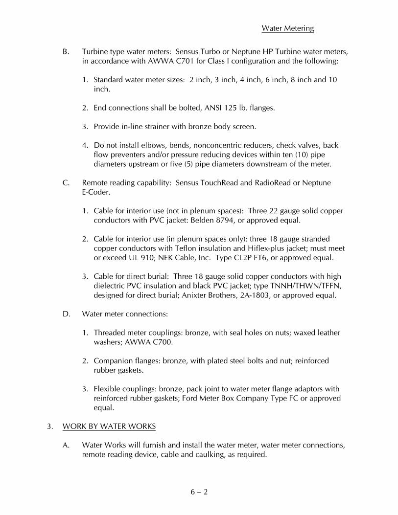
6 – 2
B. Turbine type water meters: Sensus Turbo or Neptune HP Turbine water meters, in accordance with AWWA C701 for Class I configuration and the following: 1. Standard water meter sizes: 2 inch, 3 inch, 4 inch, 6 inch, 8 inch and 10
inch. 2. End connections shall be bolted, ANSI 125 lb. flanges. 3. Provide in-line strainer with bronze body screen. 4. Do not install elbows, bends, nonconcentric reducers, check valves, back
flow preventers and/or pressure reducing devices within ten (10) pipe diameters upstream or five (5) pipe diameters downstream of the meter.
C. Remote reading capability: Sensus TouchRead and RadioRead or Neptune E-Coder. 1. Cable for interior use (not in plenum spaces): Three 22 gauge solid copper
conductors with PVC jacket: Belden 8794, or approved equal. 2. Cable for interior use (in plenum spaces only): three 18 gauge stranded
copper conductors with Teflon insulation and Hiflex-plus jacket; must meet or exceed UL 910; NEK Cable, Inc. Type CL2P FT6, or approved equal.
3. Cable for direct burial: Three 18 gauge solid copper conductors with high
dielectric PVC insulation and black PVC jacket; type TNNH/THWN/TFFN, designed for direct burial; Anixter Brothers, 2A-1803, or approved equal.
D. Water meter connections: 1. Threaded meter couplings: bronze, with seal holes on nuts; waxed leather
washers; AWWA C700. 2. Companion flanges: bronze, with plated steel bolts and nut; reinforced
rubber gaskets. 3. Flexible couplings: bronze, pack joint to water meter flange adaptors with
reinforced rubber gaskets; Ford Meter Box Company Type FC or approved equal.
3. WORK BY WATER WORKS A. Water Works will furnish and install the water meter, water meter connections, remote reading device, cable and caulking, as required.
Water Metering
6 – 3
4. WORK BY OTHERS A. Construction of all pipe and fittings; installation of electrical bonding jumper; installation of empty 1/2 inch conduit for remote reading device cable. 1. Unless otherwise directed by Water Works, empty conduit is required on all
construction except single family residential buildings. 2. Install conduit from meter to exterior wall of building; set exterior wall end
of conduit to facilitate installation and use of remote meter reading device. Obtain Water Works approval of such location.
B. For 1-1/2 inch and larger water meters, Water Works can furnish water meter for installation by others, if desired to facilitate construction of water meter setting and adjacent piping. 5. WATER METER SETTINGS A. Water Works will install water meters in water meter settings which conform with the following standards: 1. The water meter shall be located inside the building and as close as possible
to the point at which the water service pipe enters the building. 2. The water meter shall be installed in a horizontal run of pipe with the shut-
off valve, a suitable reducer and a pipe support on each side of the water meter; the horizontal run of pipe shall be at least 1 foot, but not more than 4 feet from the floor.
a. When copper tubing is used for water service connection. The
first valve inside the building shall have a flared tubing-type inlet. b. If backflow prevention devices if required, must be installed
downstream of water meter. 3. The pipe adjacent to the water meter setting shall be arranged so the water meter is, and will remain, accessible for reading, inspecting and changing the water meter. B. The contractor and/or customer are responsible for protecting the water meter from freezing; heat tapes and building insulation are not recommended for this purpose; the water meter should be located in an area which is heated by the building’s heating system.
Water Metering
6 – 4
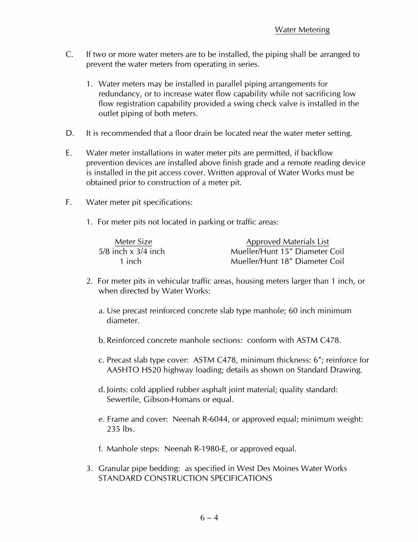
C. If two or more water meters are to be installed, the piping shall be arranged to prevent the water meters from operating in series. 1. Water meters may be installed in parallel piping arrangements for redundancy, or to increase water flow capability while not sacrificing low flow registration capability provided a swing check valve is installed in the outlet piping of both meters. D. It is recommended that a floor drain be located near the water meter setting. E. Water meter installations in water meter pits are permitted, if backflow prevention devices are installed above finish grade and a remote reading device
is installed in the pit access cover. Written approval of Water Works must be obtained prior to construction of a meter pit.
F. Water meter pit specifications:
1. For meter pits not located in parking or traffic areas:
Meter Size Approved Materials List 5/8 inch x 3/4 inch Mueller/Hunt 15” Diameter Coil
1 inch Mueller/Hunt 18” Diameter Coil 2. For meter pits in vehicular traffic areas, housing meters larger than 1 inch, or when directed by Water Works:
a. Use precast reinforced concrete slab type manhole; 60 inch minimum diameter. b. Reinforced concrete manhole sections: conform with ASTM C478. c. Precast slab type cover: ASTM C478, minimum thickness: 6”; reinforce for AASHTO HS20 highway loading; details as shown on Standard Drawing. d. Joints: cold applied rubber asphalt joint material; quality standard: Sewertile, Gibson-Homans or equal. e. Frame and cover: Neenah R-6044, or approved equal; minimum weight: 235 lbs. f. Manhole steps: Neenah R-1980-E, or approved equal. 3. Granular pipe bedding: as specified in West Des Moines Water Works STANDARD CONSTRUCTION SPECIFICATIONS
Water Metering
6 – 5
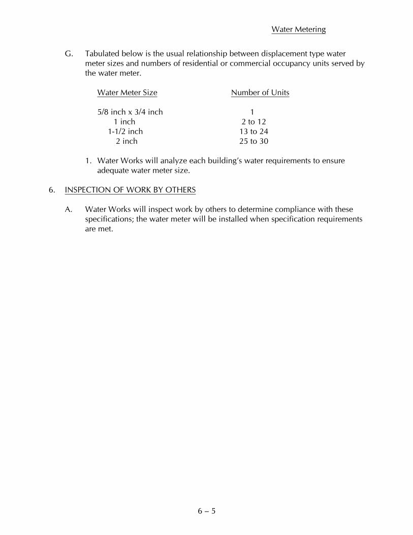
G. Tabulated below is the usual relationship between displacement type water meter sizes and numbers of residential or commercial occupancy units served by the water meter.
Water Meter Size Number of Units
5/8 inch x 3/4 inch 1 1 inch 2 to 12 1-1/2 inch 13 to 24 2 inch 25 to 30
1. Water Works will analyze each building’s water requirements to ensure adequate water meter size. 6. INSPECTION OF WORK BY OTHERS A. Water Works will inspect work by others to determine compliance with these specifications; the water meter will be installed when specification requirements are met.

SAMPLE CONTRACT DOCUMENTS
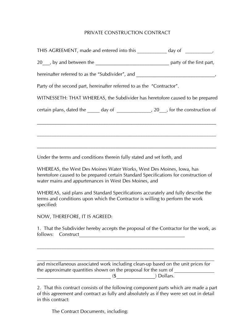
PRIVATE CONSTRUCTION CONTRACT
THIS AGREEMENT, made and entered into this ____________ day of ___________, 20___, by and between the ______________________________ party of the first part, hereinafter referred to as the “Subdivider”, and ________________________________, Party of the second part, hereinafter referred to as the “Contractor”. WITNESSETH: THAT WHEREAS, the Subdivider has heretofore caused to be prepared certain plans, dated the _____ day of ______________, 20___, for the construction of _________________________________________________________________________ _________________________________________________________________________ _________________________________________________________________________ Under the terms and conditions therein fully stated and set forth, and WHEREAS, the West Des Moines Water Works, West Des Moines, Iowa, has heretofore caused to be prepared certain Standard Specifications for construction of water mains and appurtenances in West Des Moines, and WHEREAS, said plans and Standard Specifications accurately and fully describe the terms and conditions upon which the Contractor is willing to perform the work specified: NOW, THEREFORE, IT IS AGREED: 1. That the Subdivider hereby accepts the proposal of the Contractor for the work, as follows: Construct ________________________________________________________________________ and miscellaneous associated work including clean-up based on the unit prices for the approximate quantities shown on the proposal for the sum of ($ ) Dollars. 2. That this contract consists of the following component parts which are made a part of this agreement and contract as fully and absolutely as if they were set out in detail in this contract: The Contract Documents, including:
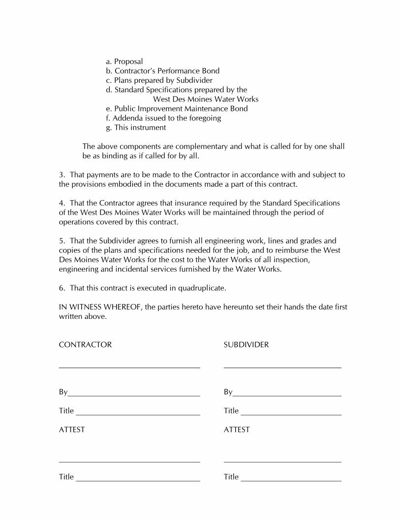
a. Proposal b. Contractor’s Performance Bond c. Plans prepared by Subdivider d. Standard Specifications prepared by the
West Des Moines Water Works e. Public Improvement Maintenance Bond
f. Addenda issued to the foregoing g. This instrument
The above components are complementary and what is called for by one shall be as binding as if called for by all.
3. That payments are to be made to the Contractor in accordance with and subject to the provisions embodied in the documents made a part of this contract. 4. That the Contractor agrees that insurance required by the Standard Specifications of the West Des Moines Water Works will be maintained through the period of operations covered by this contract. 5. That the Subdivider agrees to furnish all engineering work, lines and grades and copies of the plans and specifications needed for the job, and to reimburse the West Des Moines Water Works for the cost to the Water Works of all inspection, engineering and incidental services furnished by the Water Works. 6. That this contract is executed in quadruplicate. IN WITNESS WHEREOF, the parties hereto have hereunto set their hands the date first written above. CONTRACTOR SUBDIVIDER By By Title Title ATTEST ATTEST Title Title
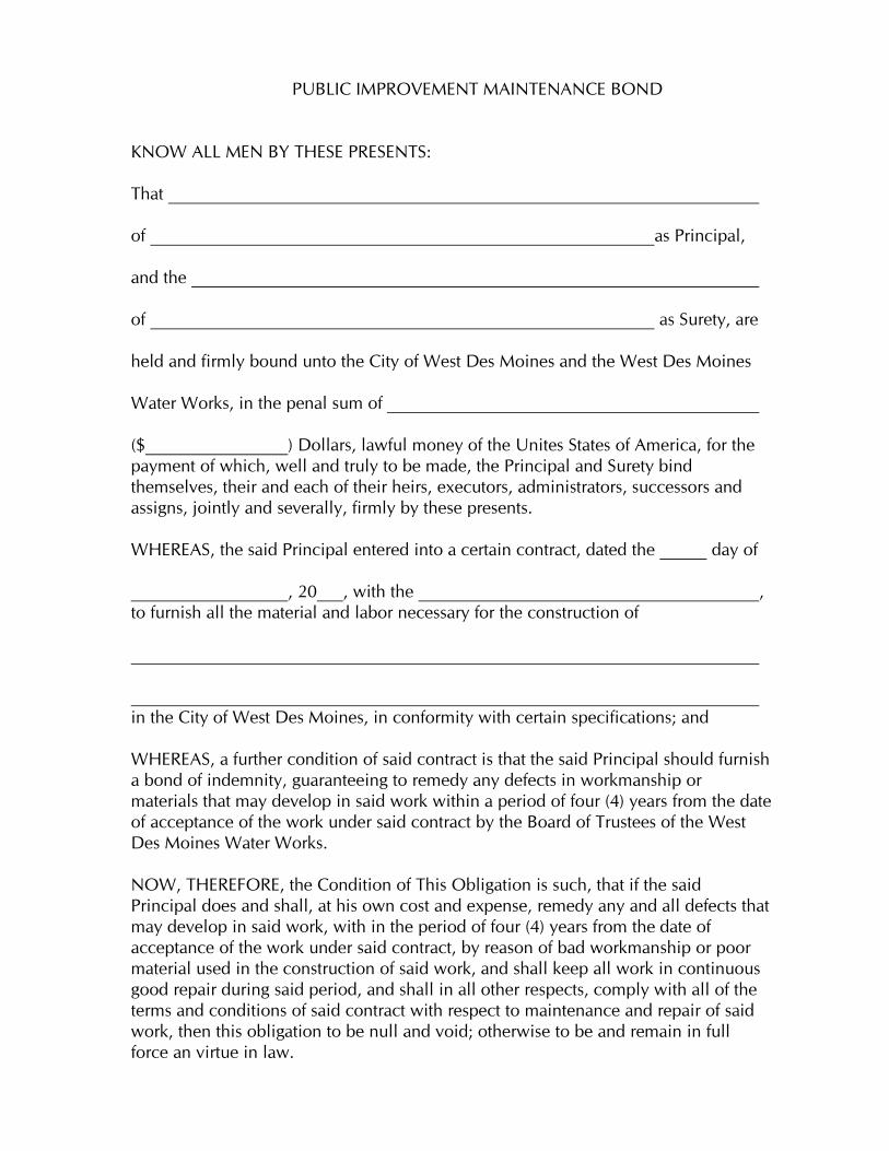
PUBLIC IMPROVEMENT MAINTENANCE BOND
KNOW ALL MEN BY THESE PRESENTS: That of as Principal, and the of as Surety, are held and firmly bound unto the City of West Des Moines and the West Des Moines Water Works, in the penal sum of ($ ) Dollars, lawful money of the Unites States of America, for the payment of which, well and truly to be made, the Principal and Surety bind themselves, their and each of their heirs, executors, administrators, successors and assigns, jointly and severally, firmly by these presents. WHEREAS, the said Principal entered into a certain contract, dated the day of , 20___, with the , to furnish all the material and labor necessary for the construction of in the City of West Des Moines, in conformity with certain specifications; and WHEREAS, a further condition of said contract is that the said Principal should furnish a bond of indemnity, guaranteeing to remedy any defects in workmanship or materials that may develop in said work within a period of four (4) years from the date of acceptance of the work under said contract by the Board of Trustees of the West Des Moines Water Works. NOW, THEREFORE, the Condition of This Obligation is such, that if the said Principal does and shall, at his own cost and expense, remedy any and all defects that may develop in said work, with in the period of four (4) years from the date of acceptance of the work under said contract, by reason of bad workmanship or poor material used in the construction of said work, and shall keep all work in continuous good repair during said period, and shall in all other respects, comply with all of the terms and conditions of said contract with respect to maintenance and repair of said work, then this obligation to be null and void; otherwise to be and remain in full force an virtue in law.
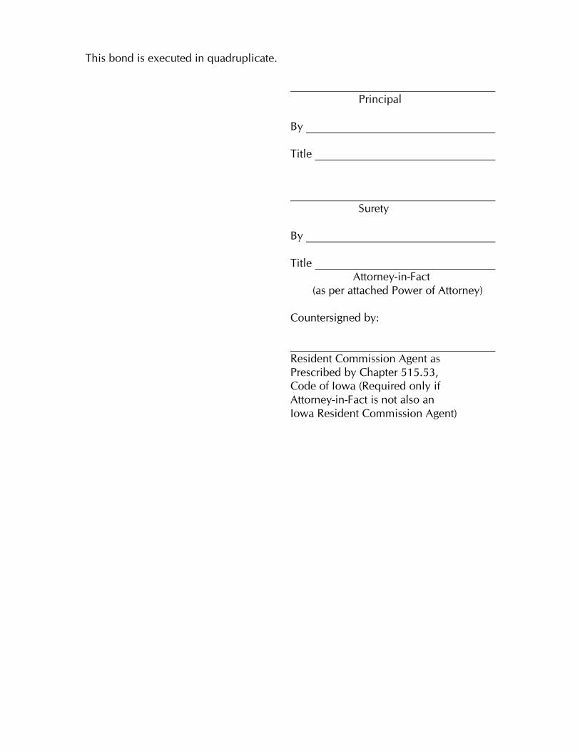
This bond is executed in quadruplicate. Principal By
Title Surety By
Title Attorney-in-Fact (as per attached Power of Attorney) Countersigned by: Resident Commission Agent as Prescribed by Chapter 515.53, Code of Iowa (Required only if Attorney-in-Fact is not also an Iowa Resident Commission Agent)

7-1
PART 7 – STANDARD DRAWINGS
INDEX
1. STANDARD WATER MAIN LOCATION 2. STANDARD WATER MAIN LOCATION AT CUL-DE-SAC 3. WATER MAIN PIPE BEDDING 4. TRACER WIRE DETAIL 5. CONCRETE ENCASEMENT 6. THRUST BLOCKS - GENERAL 7. THRUST BLOCKS – FOR OFFSETS 8. FIRE HYDRANT
9. WATER SERVICE INTO AN APARTMENT AND MULTI-OCCUPANCY COMMERCIAL BUILDINGS 10. WATER SERVICE INTO CONDOMINIUMS 11. DOMESTIC WATER INTO A DUPLEX 12. 2” AND SMALLER DOMESTIC WATER SERVICE PIPE 13. BUILDING AND IRRIGATION WATER METER GENERAL ARRANGEMENT 14. WATER METER SETTINGS 1 1/2” AND LARGER METERS 15. WATER METER SETTINGS 5/8” x 3/4” AND 1” METERS 16. DOMESTIC WATER SERVICE INTO A TOWNHOUSE (OPTION 1)
17. DOMESTIC WATER SERVICE INTO A TOWNHOUSE (OPTION 2) 18. DOMESTIC WATER SERVICE INTO A TOWNHOUSE (OPTION 3) 19. WATER METER PIT 20. REMOTE METER READING DEVICE
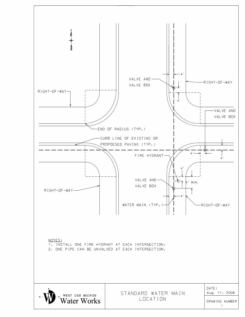
RIGHT-OF-WAY
RIGHT-OF-WAY
RIGHT-OF-WAY
END OF RADIUS (TYP.)
PROPOESED PAVING (TYP.)
CURB LINE OF EXISTING OR
VALVE BOX
VALVE AND
WATER MAIN (TYP.)
VALVE BOX
VALVE AND
VALVE BOX
VALVE AND
4’
5’ MIN.
4’
4’
4’
4’
4’
NOTES:
2. ONE PIPE CAN BE UNVALVED AT EACH INTERSECTION.
1. INSTALL ONE FIRE HYDRANT AT EACH INTERSECTION.
N
RIGHT-OF-WAY
FIRE HYDRANT
WEST DES MOINES
Water Works
1
DRAWING NUMBERLOCATION
STANDARD WATER MAIN Aug. 11, 2008
DATE:
INTERSECTION.
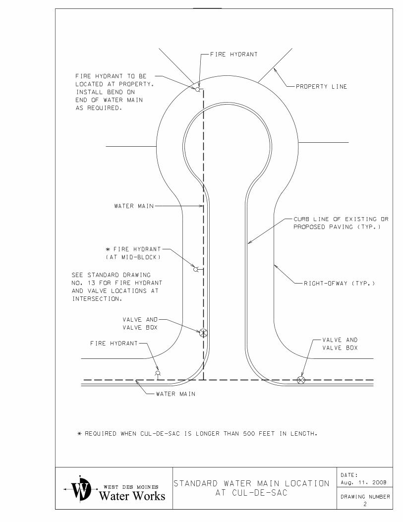
AND VALVE LOCATIONS AT
NO. 13 FOR FIRE HYDRANT
SEE STANDARD DRAWING
PROPERTY LINE
WATER MAIN
PROPOSED PAVING (TYP.)
CURB LINE OF EXISTING OR
RIGHT-OFWAY (TYP.)
VALVE BOX
VALVE AND
FIRE HYDRANT
WATER MAIN
VALVE BOX
VALVE AND
FIRE HYDRANT
(AT MID-BLOCK)
* FIRE HYDRANT
AS REQUIRED.
END OF WATER MAIN
INSTALL BEND ON
LOCATED AT PROPERTY.
FIRE HYDRANT TO BE
WEST DES MOINES
Water Works
2
DRAWING NUMBERAT CUL-DE-SAC
STANDARD WATER MAIN LOCATION
* REQUIRED WHEN CUL-DE-SAC IS LONGER THAN 500 FEET IN LENGTH.
Aug. 11, 2008
DATE:
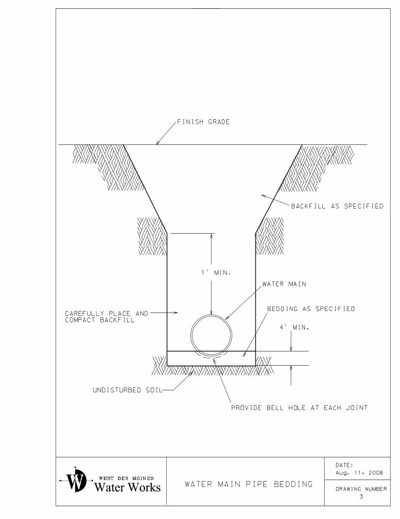
UNDISTURBED SOIL
WEST DES MOINES
Water Works
4’ MIN.
PROVIDE BELL HOLE AT EACH JOINT
WATER MAIN
BEDDING AS SPECIFIED
COMPACT BACKFILL
CAREFULLY PLACE AND
1’ MIN.
BACKFILL AS SPECIFIED
FINISH GRADE
3
DRAWING NUMBERWATER MAIN PIPE BEDDING
Aug. 11, 2008
DATE:
AS SPECIFIED
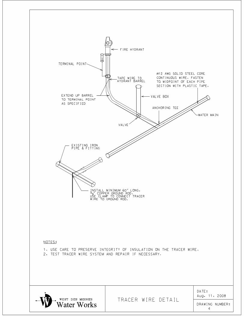
TO TERMINAL POINT
EXTEND UP BARREL
2. TEST TRACER WIRE SYSTEM AND REPAIR IF NECESSARY.
1. USE CARE TO PRESERVE INTEGRITY OF INSULATION ON THE TRACER WIRE.
NOTES:
TRACER WIRE DETAILWEST DES MOINES
Water Works
WATER MAIN
FIRE HYDRANT
TAPE WIRE TO
HYDRANT BARREL
EXISTING IRON
PIPE & FITTING
INSTALL MINIMUM 60" LONG,
�" COPPER GROUND ROD.
USE CLAMP TO CONNECT TRACER
WIRE TO GROUND ROD.
VALVE
ANCHORING TEE
#12 AWG SOLID STEEL CORE
CONTINUOUS WIRE. FASTEN
TO MIDPOINT OF EACH PIPE
SECTION WITH PLASTIC TAPE.
TERMINAL POINT
VALVE BOX
X
4
DRAWING NUMBER:
Aug. 11, 2008
DATE:
D
2. INSTALL AND SUPPORT WATER MAIN AS SPECIFIED.
TRENCH WALLS MAY BE USED TO FORM CONCRETE.
1. PROVIDE MINIMUM CONCRETE THICKNESS OF 8" AROUND PIPE.
FINISH GRADE
AS SPECIFIED
BACKFILL:
AS SPECIFIED
CONCRETE ENCASEMENT:
WATER MAIN
UNDISTURBED SOIL
NOTES:
WEST DES MOINES
Water Works
CONCRETE ENCASEMENT
5
DRAWING NUMBER
Aug. 11, 2008
DATE:
BEND TEE
DEAD END DEAD END
(ALTERNATE)
BY WATER WORKS.
4. USE ALTERNATE THRUST BLOCK AT DEAD ENDS ONLY WHEN PERMITTED
3. FORM VERTICAL SURFACES OF POURED CONCRETE THRUST BLOCKS.
2. EXTEND THRUST BLOCKS TO UNDISTURBED SOIL.
(MIN. THICKNESS = 18")
1. REFER TO SPECIFICATIONS TO DETERMINE THRUST BLOCK SIZE.
NOTES:
CONCRETE THRUST BLOCK
CONCRETE THRUST BLOCK
WATER MAIN
(2)�" ANCHOR RODS
WATER MAINWATER MAIN
CONCRETE THRUST BLOCK
WATER MAIN
WEST DES MOINES
Water Works
DATE:
DRAWING NUMBER
6
THRUST BLOCKS - GENERAL
Aug. 11, 2008
THRUST BLOCK
ANCHOR-TYPE
ADJACENT TO VERTICAL OFFSETS.
FIRST TWO FULL PIPE LENGTHS
VERTICAL OFFSETS AND FOR
RETAINER GLANDS FOR ALL
USE DUCTILE IRON PIPE AND
HORIZONTAL OFFSET
VERTICAL OFFSET
3. FORM VERTICAL SURFACES OF POURED CONCRETE THRUST BLOCKS.
2. EXTEND THRUST BLOCKS TO UNDISTURBED SOIL.
(MIN. THICKNESS = 18")
1. REFER TO SPECIFICATIONS TO DETERMINE THRUST BLOCK SIZE.
NOTES:
AS SPECIFIED
USE ANCHOR RODS
WATER MAIN
WATER MAIN
CONCRETE THRUST BLOCK (TYP.)
CONCRETE THRUST BLOCK (TYP.)
WEST DES MOINES
Water Works
DATE:
DRAWING NUMBER
7
THRUST BLOCKS FOR OFFSETS
Aug. 11, 2008
VALVE BOX
TRENCH WALLS
WATER MAIN
BLOCK
THRUST
CONCRETE
SPECIFICATIONS.
REQUIRED. SEE
ELBOW WHEN
USE ANCHORING
ANCHORING TEE
BLOCK
CONCRETE
SOLID
TO UNDISTURBED
SOIL.
WIRE
TRACER
UNDISTURBED SOIL
FINISH GRADE
TERMINAL POINT
FIRE HYDRANT
WATER
MAINVALVE
GATE
NOTES:
1. WRAP FIRE HYDRANT, PIPE, VALVE, VALVE BOX, AND TEE OR ELBOW IN PLASTIC
AS SPECIFIED.
ANCHORING PIPE
OR ANCHORING
COUPLING
AS REQUIRED
SPECIFIED
DEPTH AS
Water Works
WEST DES MOINES
GRADE
ABOVE FINISH
AT OR JUST
GRADE MARK
CONRETE THRUST
BLOCK. EXTEND
INLET.
ABOVE HYDRANT
BEDDING TO 1’ 6"
GRANULAR PIPE
BACKFILL WITH
1’ 11" max.
1’ 6" MIN.
8
DRAWING NUMBER
FIRE HYDRANT
GRADE MARK.
REGARDLESS OF LOCATION OF HYDRANT
AT LEAST 1’-6" ABOVE FINISH GRADE,
CENTER LINE OF NOZZLES MUST BE
Aug. 11, 2008
DATE:
2. INSTALL TRACER WIRE AS SHOWN ON STANDARD DRAWING NUMBER 4
M
M
PU
BLI
C
WA
TE
R
MAI
N
(5’ MIN. FROM BLDG.)
SERVICE PIPE (PRIVATE)
DOMESTIC WATER
(PRIVATE)
FIRE SERVICE PIPE
WEST DES MOINES
Water Works
COMMERCIAL BUILDINGS
AND MULTI-OCCUPANCY
WATER SERVICE INTO APARTMENT
9
DRAWING NUMBER
CURB VALVE
LEGEND
WATER METER
2. SUB-METERING OF INDIVIDUAL UNITS IS AT THE OWNERS DISCRETION.
1. EACH BUILDING WILL HAVE A MASTER METER.
NOTES:
Aug. 11, 2008
DATE:
M
M
M M
M
MM
M
M
M
M
M
M
METER ROOM
PU
BLI
C
WA
TE
R
MAI
N
(5’ MIN. FROM BLDG.)
SERVICE PIPE (PRIVATE)
DOMESTIC WATER
(PRIVATE)
FIRE SERVICE PIPE
WEST DES MOINES
Water Works CONDOMINIUMS
WATER SERVICE INTO
10
DRAWING NUMBER
LEGEND
CURB VALVE
WATER METER
METER THROUGH A COMMON AREA.
3. WATER WORKS MUST BE PROVIDED WITH CONTINUOUS ACCESS TO THE
2. METERS MAY BE GROUPED IN ONE OR MORE LOCATIONS.
1. EACH OCCUPANCY UNIT MUST HAVE ITS OWN WATER METER.
NOTES:
Aug. 11, 2008
DATE:
722
724
PU
BLI
C
WA
TE
R
MAI
N
M
M
DOMESTIC WATER SERVICE (PRIVATE)
DOMESTIC WATER SERVICE (PRIVATE)
WEST DES MOINES
Water Works A DUPLEX
DOMESTIC WATER INTO
11
DRAWING NUMBER
LEGEND
CURB VALVE
Aug. 11, 2008
DATE:
"K" COPPER
SHALL BE TYPE
SERVICE PIPE
THE ADJACENT GROUND
BE INSTALLED & MAINTAINED LEVEL WITH
COVER FOR CURB VALVE BOX SHALL
PROPERTY LINE
CURB VALVE
REQUIRED AS SPECIFIED
SERVICE SADDLE WHEN
WATER MAIN
VALVE
CORPORATION PAVEMENT
CURBING
VALVE
BALL
4’
Max
VALVE
BALL
METER
WATER
DEVICE
READING
METER
REMOTE
CABLE TO
WIRE
THREE
SIDEWALK
6’ MIN.
1’
MI
N.
5’
MI
N. 1’ MIN.
4.
5’
MI
N.
WEST DES MOINES
Water Works WATER SERVICE PIPE
2" AND SMALLER DOMESTIC
12
DRAWING NUMBER
READING DEVICE
REMOTE METER
4’TO 6’
Aug. 11, 2008
DATE:
AVOID INSTALLATION IN DRIVEWAYS WHEN POSSIBLE.
1. UNDER NO CIRCUMSTANCES SHOULD THE CURB VALVE BE INSTALLED IN SIDEWALK.
NOTES:
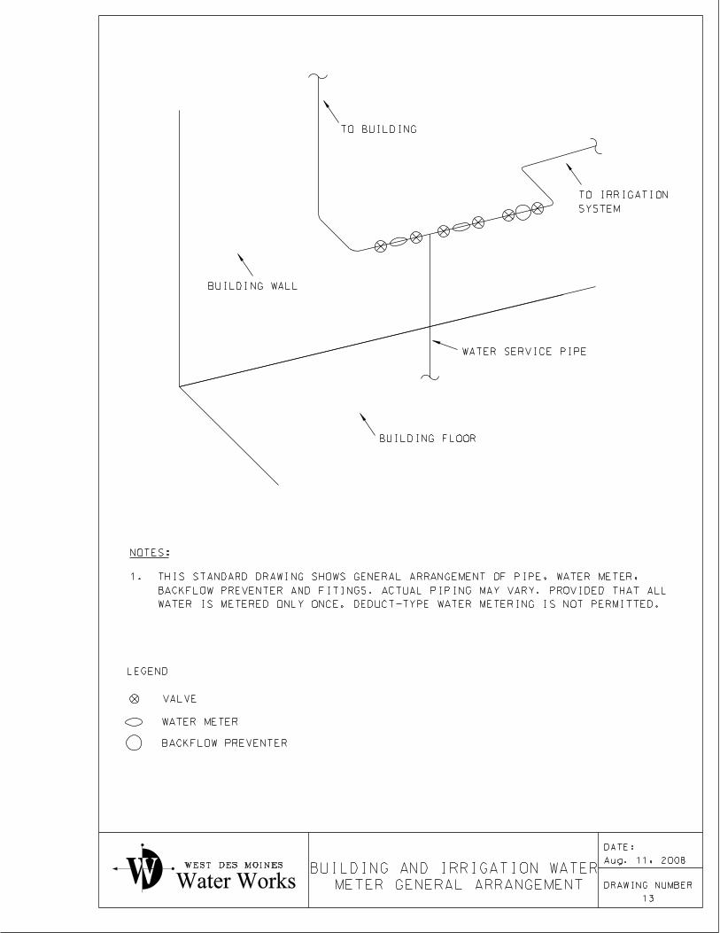
WEST DES MOINES
Water Works
METER GENERAL ARRANGEMENT
BUILDING AND IRRIGATION WATER
13
DRAWING NUMBER
TO BUILDING
SYSTEM
TO IRRIGATION
BUILDING WALL
WATER SERVICE PIPE
BUILDING FLOOR
NOTES:
WATER IS METERED ONLY ONCE. DEDUCT-TYPE WATER METERING IS NOT PERMITTED.
BACKFLOW PREVENTER AND FITINGS. ACTUAL PIPING MAY VARY. PROVIDED THAT ALL
1. THIS STANDARD DRAWING SHOWS GENERAL ARRANGEMENT OF PIPE, WATER METER,
LEGEND
VALVE
WATER METER
BACKFLOW PREVENTER
Aug. 11, 2008
DATE:
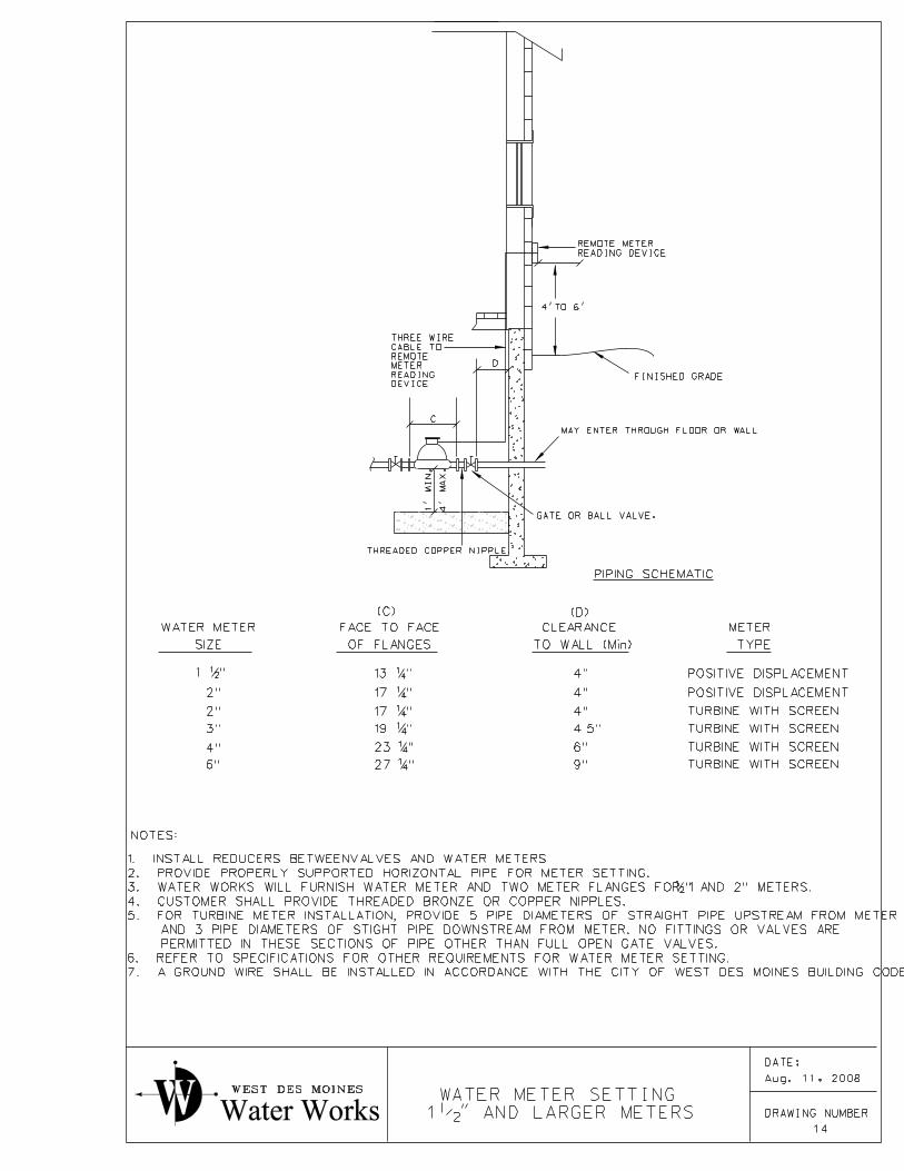
NOTES:
D
C
OF FLANGES
FACE TO FACE
SIZE
WATER METER
TYPE
METER
"211
2"
2"
3"
4"
6"
"4113
"4117
"4117
"4119
"4123
"4127
4.5"
POSITIVE DISPLACEMENT
POSITIVE DISPLACEMENT
(C) (D)
THREADED COPPER NIPPLE
PIPING SCHEMATIC
MAY ENTER THROUGH FLOOR OR WALL
TO WALL (Min)
CLEARANCE
TURBINE WITH SCREEN
TURBINE WITH SCREEN
TURBINE WITH SCREEN
TURBINE WITH SCREEN9"
6"
4"
4"
4"
1’
MI
N.
4’
MA
X.
GATE OR BALL VALVE.
WEST DES MOINES
Water Works
1�" AND LARGER METERS
WATER METER SETTING
DEVICE
READING
METER
REMOTE
CABLE TO
THREE WIRE
READING DEVICE
REMOTE METER
14
DRAWING NUMBER
4’TO 6’
FINISHED GRADE
7. A GROUND WIRE SHALL BE INSTALLED IN ACCORDANCE WITH THE CITY OF WEST DES MOINES BUILDING CODE.
6. REFER TO SPECIFICATIONS FOR OTHER REQUIREMENTS FOR WATER METER SETTING.
PERMITTED IN THESE SECTIONS OF PIPE OTHER THAN FULL OPEN GATE VALVES.
AND 3 PIPE DIAMETERS OF STIGHT PIPE DOWNSTREAM FROM METER. NO FITTINGS OR VALVES ARE
5. FOR TURBINE METER INSTALLATION, PROVIDE 5 PIPE DIAMETERS OF STRAIGHT PIPE UPSTREAM FROM METER
4. CUSTOMER SHALL PROVIDE THREADED BRONZE OR COPPER NIPPLES.
" AND 2" METERS.213. WATER WORKS WILL FURNISH WATER METER AND TWO METER FLANGES FOR 1
2. PROVIDE PROPERLY SUPPORTED HORIZONTAL PIPE FOR METER SETTING.
1. INSTALL REDUCERS BETWEENVALVES AND WATER METERS.
Aug. 11, 2008
DATE:
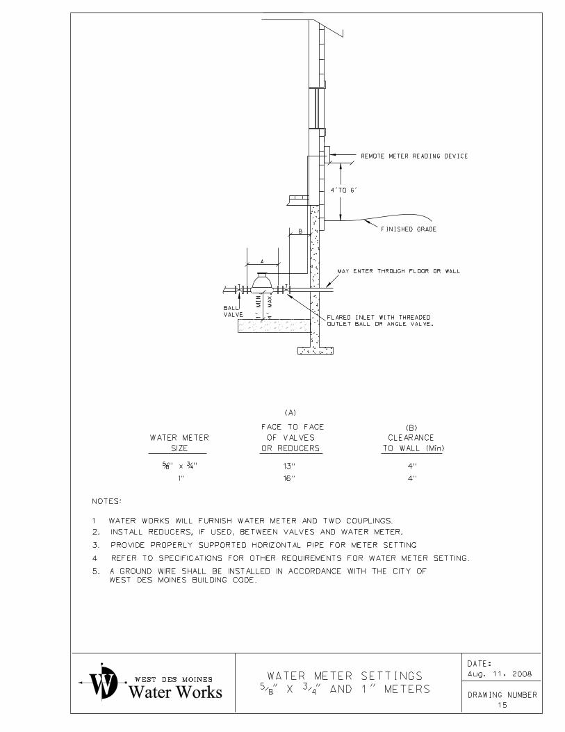
VALVE
BALL
B
A
OUTLET BALL OR ANGLE VALVE.
FLARED INLET WITH THREADED
SIZE
WATER METER
1"
3. PROVIDE PROPERLY SUPPORTED HORIZONTAL PIPE FOR METER SETTING.
(A)
(B)
13"
16"
4"
4"
"43" x 8
5
2. INSTALL REDUCERS, IF USED, BETWEEN VALVES AND WATER METER.
4. REFER TO SPECIFICATIONS FOR OTHER REQUIREMENTS FOR WATER METER SETTING.
OR REDUCERS
OF VALVES
FACE TO FACE
MAY ENTER THROUGH FLOOR OR WALL
NOTES:
TO WALL (Min)
CLEARANCE
1’
MI
N.
4’
MA
X.
WEST DES MOINES BUILDING CODE.
A GROUND WIRE SHALL BE INSTALLED IN ACCORDANCE WITH THE CITY OF5.
1. WATER WORKS WILL FURNISH WATER METER AND TWO COUPLINGS.
WEST DES MOINES
Water Works �" X �" AND 1" METERS
WATER METER SETTINGS
15
DRAWING NUMBER
REMOTE METER READING DEVICE
4’TO 6’
FINISHED GRADE
Aug. 11, 2008
DATE:
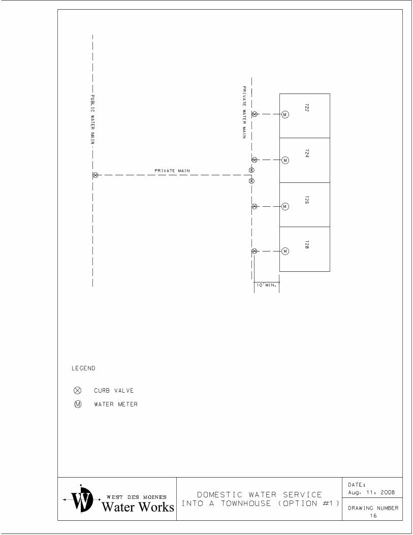
PRIVATE MAIN
M
M
M
M
M
72
27
24
72
67
28
PRI
VA
TE
WA
TE
R
MAI
N
PU
BLI
C
WA
TE
R
MAI
N
10’MIN.
WEST DES MOINES
Water Works INTO A TOWNHOUSE (OPTION #1)
DOMESTIC WATER SERVICE
16
DRAWING NUMBER
LEGEND
CURB VALVE
WATER METER
Aug. 11, 2008
DATE:
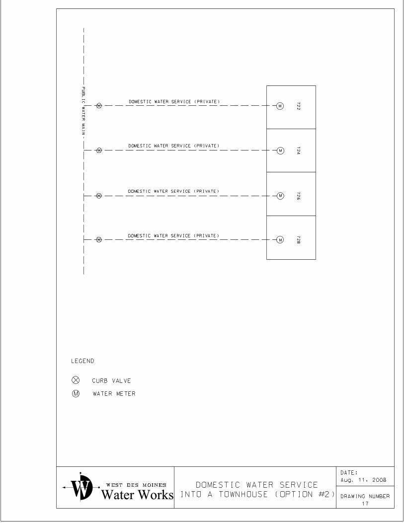
M
M
M
M
M
72
27
24
72
67
28
PU
BLI
C
WA
TE
R
MAI
N
DOMESTIC WATER SERVICE (PRIVATE)
DOMESTIC WATER SERVICE (PRIVATE)
DOMESTIC WATER SERVICE (PRIVATE)
DOMESTIC WATER SERVICE (PRIVATE)
WEST DES MOINES
Water Works INTO A TOWNHOUSE (OPTION #2)
DOMESTIC WATER SERVICE
17
DRAWING NUMBER
LEGEND
CURB VALVE
WATER METER
Aug. 11, 2008
DATE:
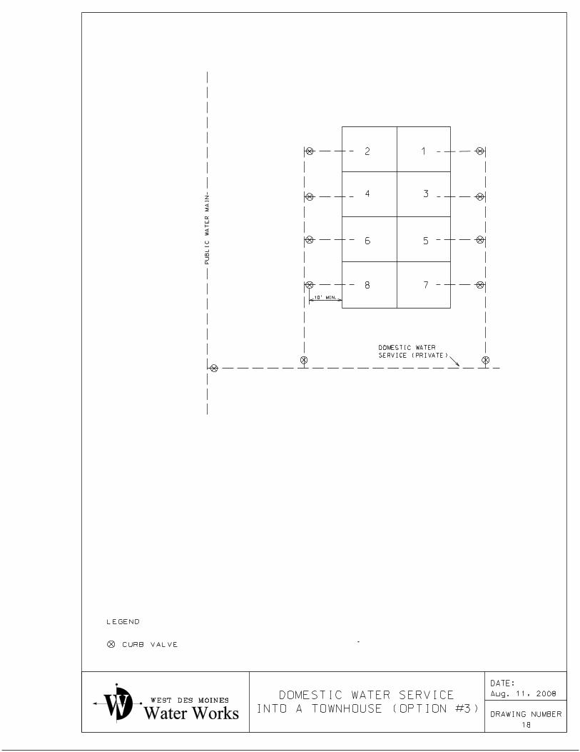
12
34
56
78
WEST DES MOINES
Water Works
18
DRAWING NUMBER
PU
BLI
C
WA
TE
R
MAI
N
SERVICE (PRIVATE)
DOMESTIC WATER
10’ MIN.
INTO A TOWNHOUSE (OPTION #3)
DOMESTIC WATER SERVICE
LEGEND
CURB VALVE
Aug. 11, 2008
DATE:
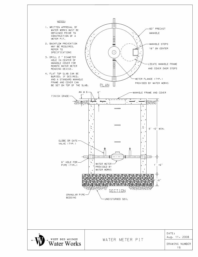
NOTES:
METER PIT.
CONSTRUCTION OF A
OBTAINED PRIOR TO
WATER WORKS MUST BE
1. WRITTEN APPROVAL OF
READING DEVICE.
REMOTE WATER METER
MANHOLE COVER FOR
HOLE IN CENTER OF
3. DRILL 2 " DIAMETER
SPECIFICATIONS
REFER TO
MAY BE REQUIRED.
2. BACKFLOW PREVENTION
BE SET ON TOP OF THE SLAB.
FRAME AND COVER CAN
AND A STANDARD MANHOLE
BURIED, IF DESIRED,
4. FLAT TOP SLAB CAN BE
PLAN
SECTION
BEDDING
GRANULAR PIPE
UNDISTURBED SOIL
WATER WORKS
PROVIDED BY
WATER METERPIPE (TYP.)
6" HOLE FOR
VALVE (TYP.)
GLOBE OR GATE
1’-0"
1’ -6"
5’ -0" MIN.
6" MANHOLE FRAME AND COVER#4 @ 6
2"FINISH GRADE
PROVIDED BY WATER WORKS
METER FLANGE (TYP.)
AND COVER OVER STEPS
LOCATE MANHOLE FRAME
16" ON CENTER
MANHOLE STEPS
MANHOLE
60" PRECAST
WEST DES MOINES
Water Works
19
DRAWING NUMBER
WATER METER PITAug. 11, 2008
DATE:
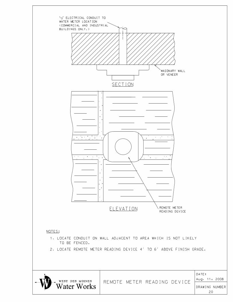
SECTION
OR VENEER
MASONARY WALL
BUILDINGS ONLY.)
(COMMERCIAL AND INDUSTRIAL
WATER METER LOCATION
�" ELECTRICAL CONDUIT TO
ELEVATIONREADING DEVICE
REMOTE METER
NOTES:
TO BE FENCED.
1. LOCATE CONDUIT ON WALL ADJACENT TO AREA WHICH IS NOT LIKELY
.
.
.
.
.
..
. .
.
..
.
.. .
..
.
.
..
.
.
.
.
.
.
.
..
.
.
.
.
.
.
.
...
..
.
.
.
.
.
.
.
.
.
..
.
.
.
.
.
.
.
.
.
.
.
..
.
.
.
..
.
...
.
.
.
.
..
WEST DES MOINES
Water Works
2. LOCATE REMOTE METER READING DEVICE 4’ TO 6’ ABOVE FINISH GRADE.
REMOTE METER READING DEVICE
20
DRAWING NUMBER
Aug. 11, 2008
DATE: