Embed Size (px)
Citation preview
STANDARD DETAILS
AND
SPECIFICATIONS
DEPARTMENT OF PUBLIC WORKS
ENGINEERING DIVISION
JUNE 2012
All “Standard Details and Specifications” are also available at www.prcity.com
CITY OF EL PASO DE ROBLES
DEPARTMENT OF PUBLIC WORKS
STANDARD DETAILS AND SPECIFICATIONS
FOR PUBLIC WORKS CONSTRUCTION
AND COMMUNITY DEVELOPMENT
Adopted June 19, 2012 by Resolution No. 12-100 of the City Councilof the City of El Paso de Robles
Duane Picanco, MayorFred Strong, Councilman
Ed Steinbeck, CouncilmanJohn Hamon, Councilman Nick Gilman, Councilman
Jim App, City ManagerDoug Monn, Director of Public Works
Ditas Esperanza, Capital Projects EngineerChristopher Alakel, Water Division Manager
Matt Thompson, Wastewater Division ManagerJohn Falkenstien, City Engineer
i
CITY OF EL PASO DE ROBLESSTANDARD SPECIFICATIONS AND DETAILS
Table of Contents
SECTION I - GENERAL REQUIREMENTS PAGE
I-1. Purpose................................................................................................................... 1I-2. Definitions ............................................................................................................... 1I-3. Encroachment Permit ............................................................................................. 1
SECTION II - PREPARATION OF PLANS
II-1. General ................................................................................................................... 2II-2. Design Alternatives ................................................................................................. 2II-3. Title Sheet and Plan Preparation............................................................................ 2II-4. Grading Plans ........................................................................................................ 3II-5. Composite Utility Plan ............................................................................................ 3II-6. Street Improvement Plans ...................................................................................... 3II-7. Underground Sewer, Water and Storm Drain Plans .............................................. 4II-8. Erosion Control Plans ............................................................................................. 4II-9. Record Drawings..................................................................................................... 4II-10. Landscape Plans .................................................................................................... 5
SECTION III – CONSTRUCTION OBSERVATION AND STORM WATER QUALITY MANAGEMENT
III-1. General ................................................................................................................... 6III-2. Acceptance of Improvements ................................................................................. 6III-3. Storm Water Quality Best Management Practices ................................................. 6
SECTION IV - STREETS
IV-1. Design Guidelines................................................................................................... 14IV-2. Materials.................................................................................................................. 15IV-3. Construction Guidelines.......................................................................................... 16IV-4. Streets Exempt From Improvements ...................................................................... 17
SECTION V - STORM DRAINS, STORM WATER QUALITY AND WATERSHED PROTECTION
V-1. General ............................................................................................................... 18V-2. Design Guidelines .................................................................................................. 19V-3. Materials ............................................................................................................... 23V-4. Construction Guidelines.......................................................................................... 24
ii
SECTION VI – SANITARY SEWERS
VI-1. Design Guidelines................................................................................................... 25VI-2. Materials ............................................................................................................... 27VI-3. Construction Guidelines.......................................................................................... 28VI-4. Testing ............................................................................................................... 30
SECTION VII – WATER
VII-1. Design Guidelines................................................................................................... 33VII-2. Materials.................................................................................................................. 36VII-3. Construction Guidelines.......................................................................................... 37VII-4. Testing .................................................................................................................... 40
iii
SECTION VIII
STANDARD DRAWING INDEX
DRAWING DESCRIPTION DRAWING NO.
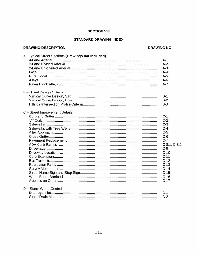
A - Typical Street Sections (Drawings not included)4-Lane Arterial............................................................................................................ A-12-Lane Divided Arterial .............................................................................................. A-22-Lane Un-divided Arterial ......................................................................................... A-3Local ................................................................................................................… A-4Rural Local ................................................................................................................. A-5Alleys .................................................................................................................... A-6Paver Block Alleys ..................................................................................................... A-7
B – Street Design CriteriaVertical Curve Design, Sag........................................................................................ B-1Vertical Curve Design, Crest...................................................................................... B-2Hillside Intersection Profile Criteria............................................................................ B-3
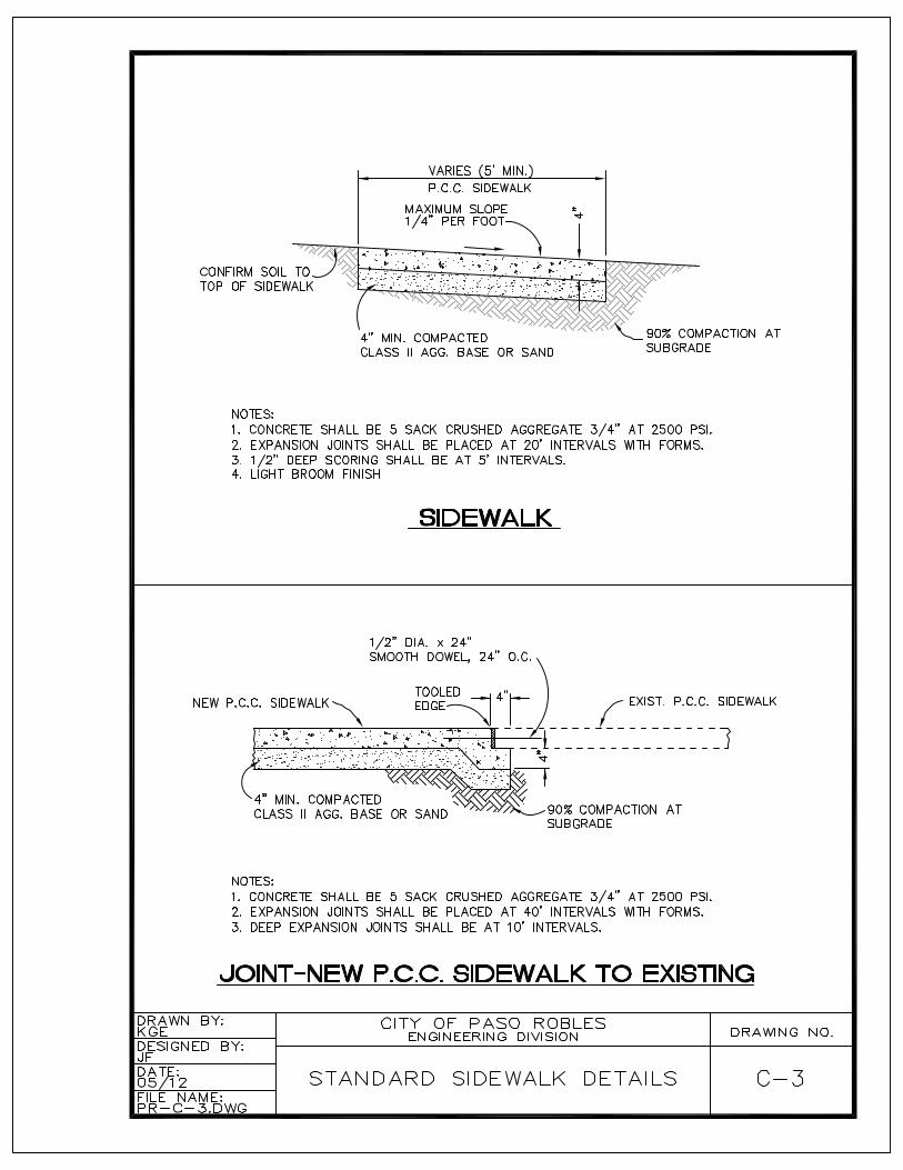
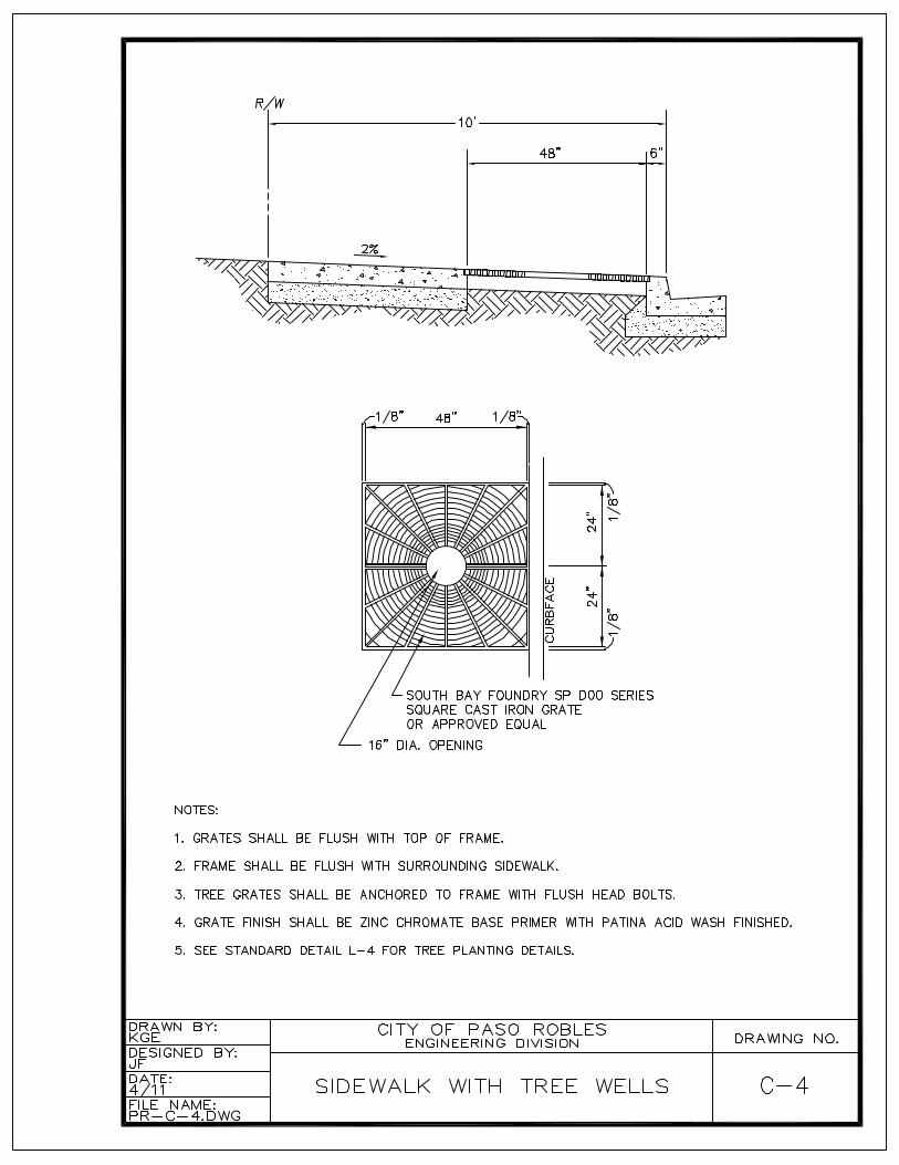
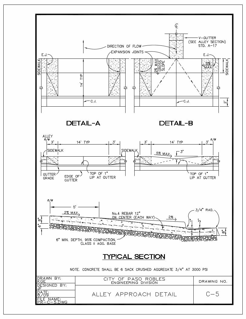
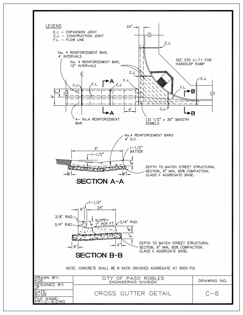
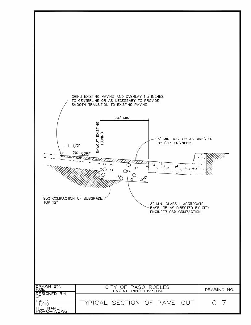
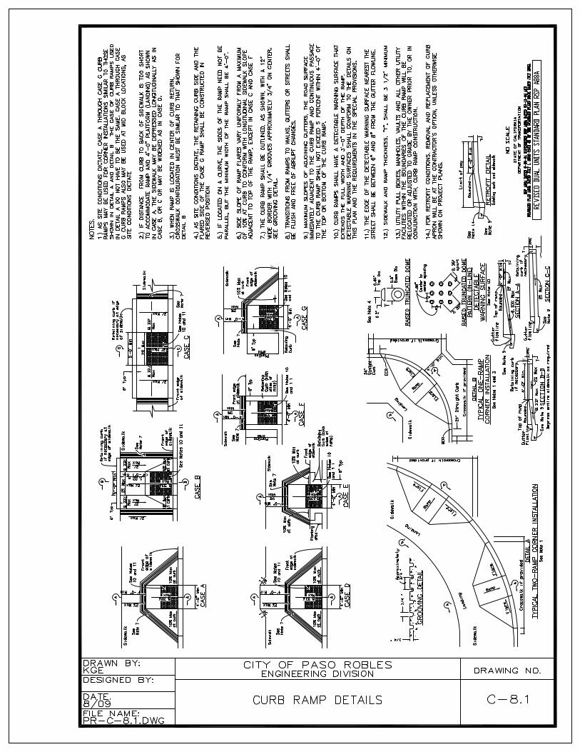
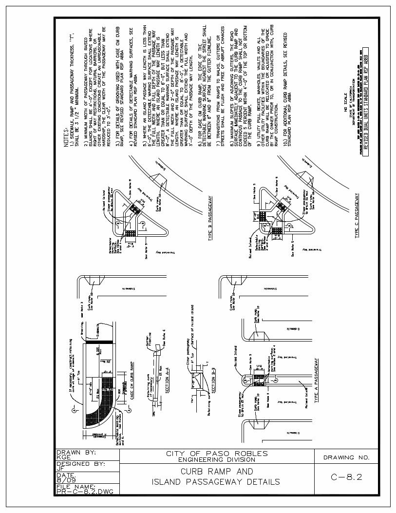
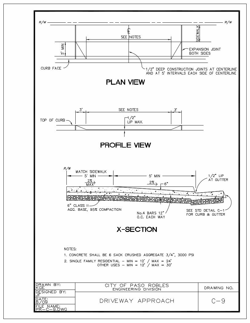
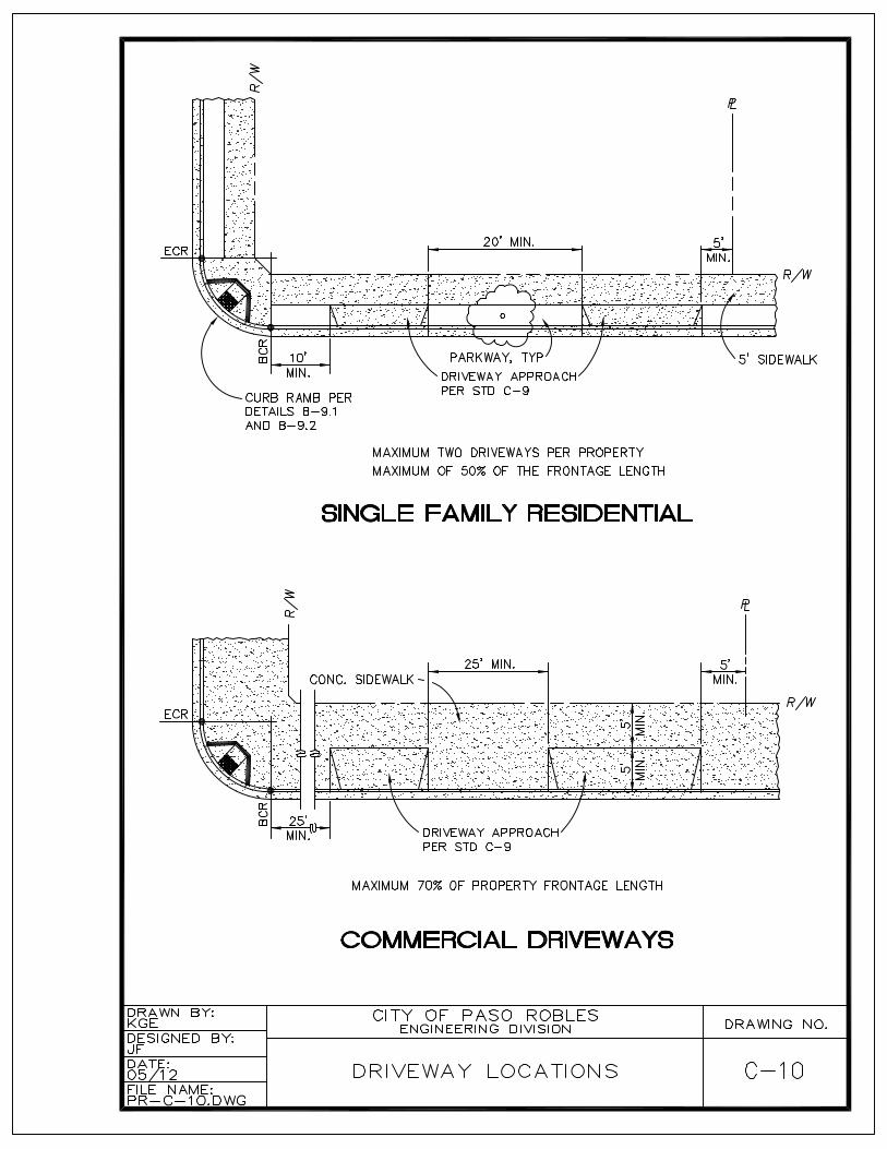
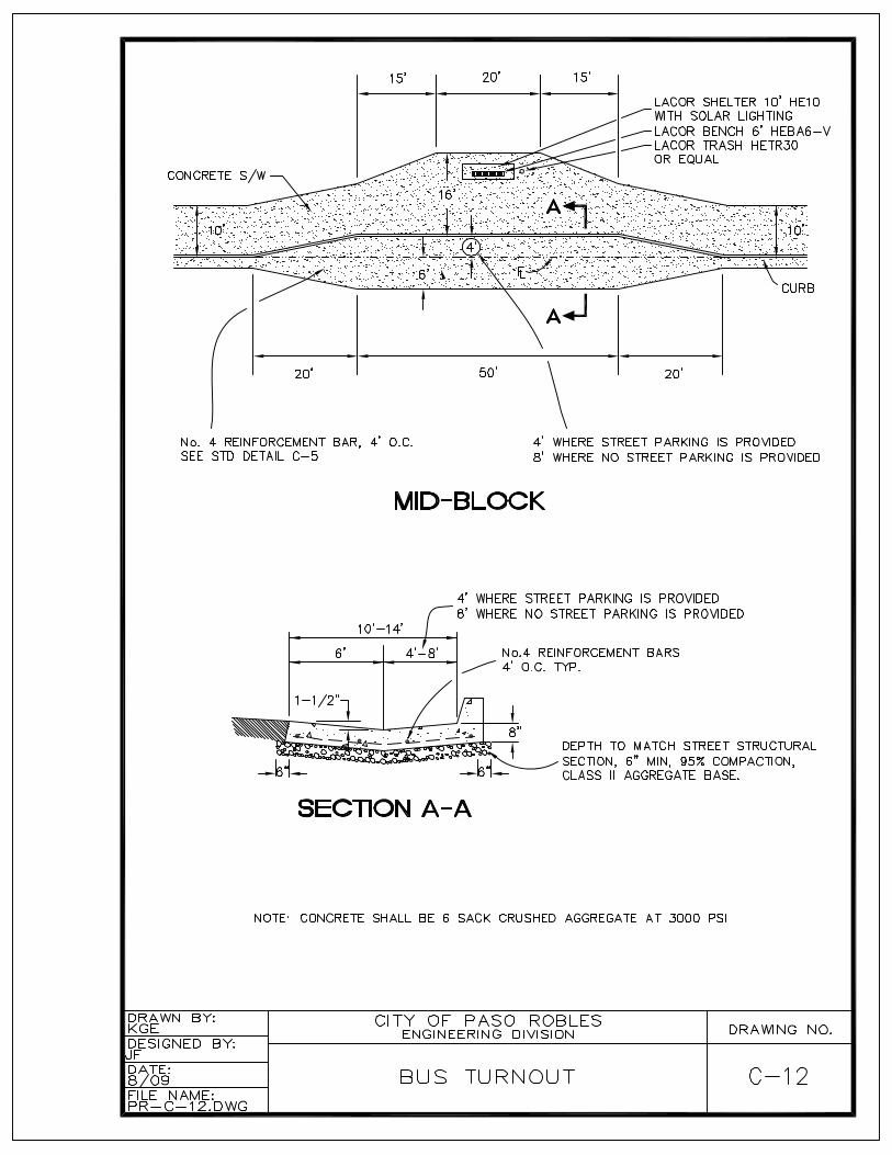
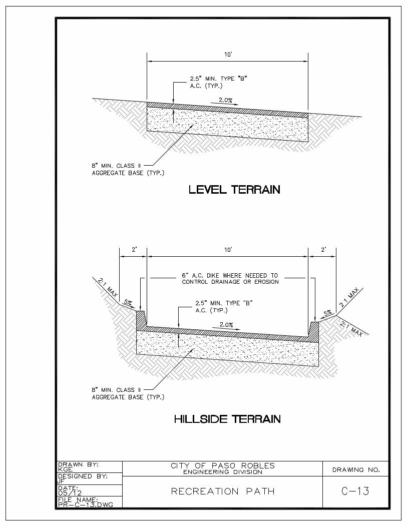
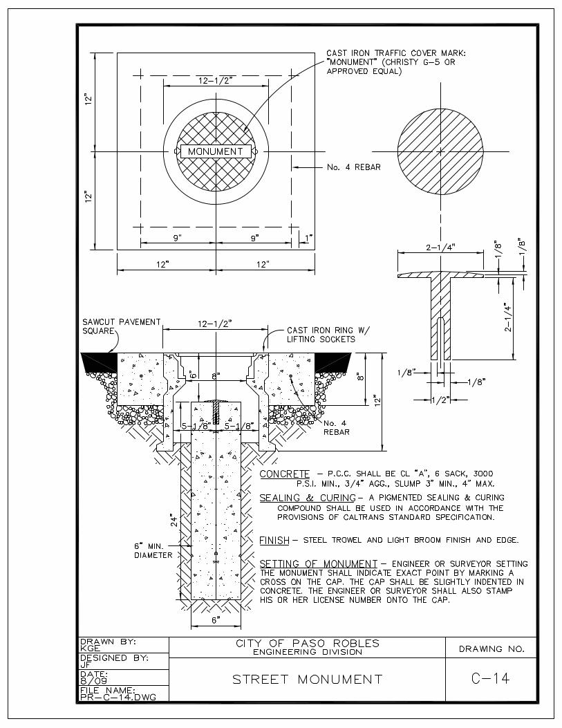
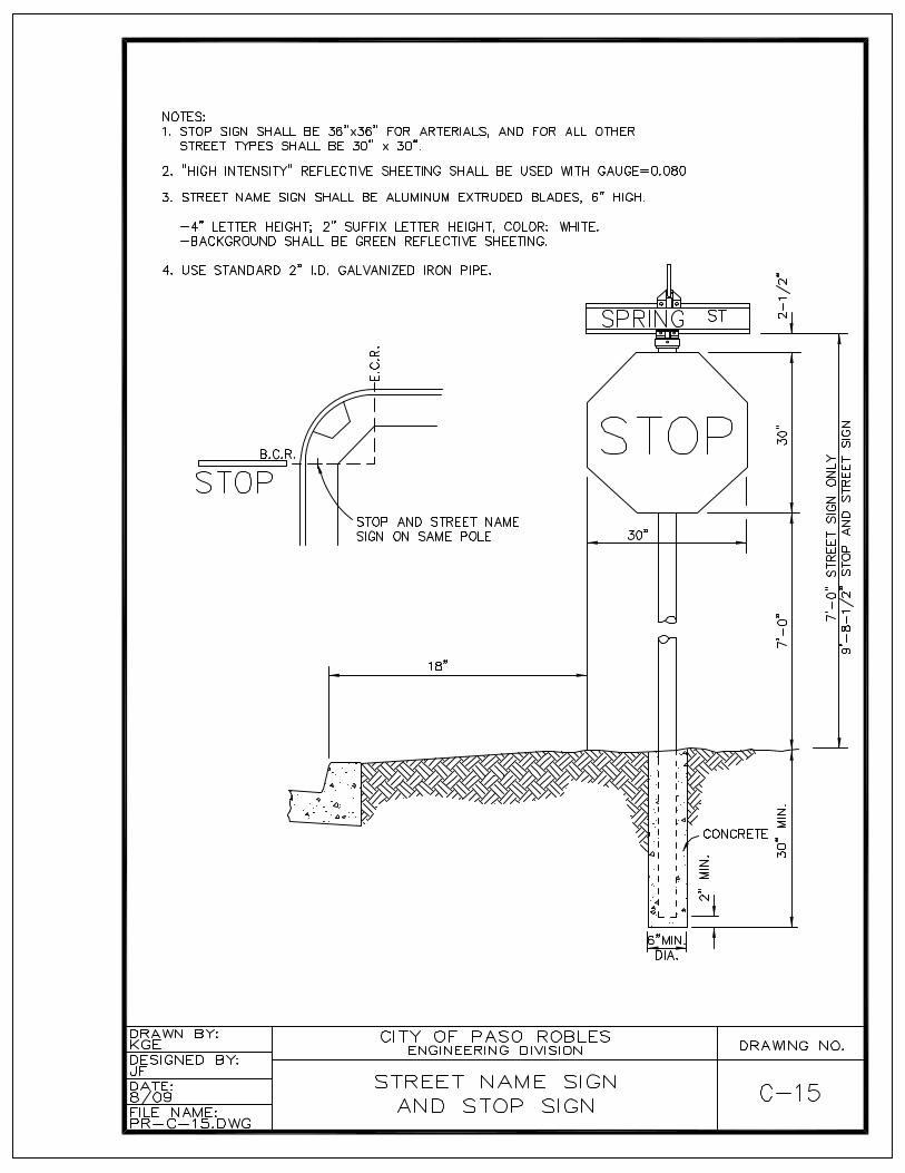
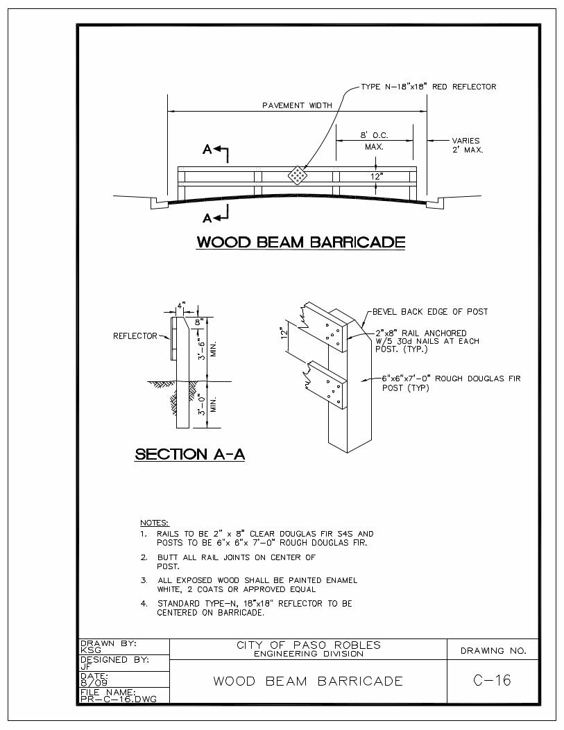
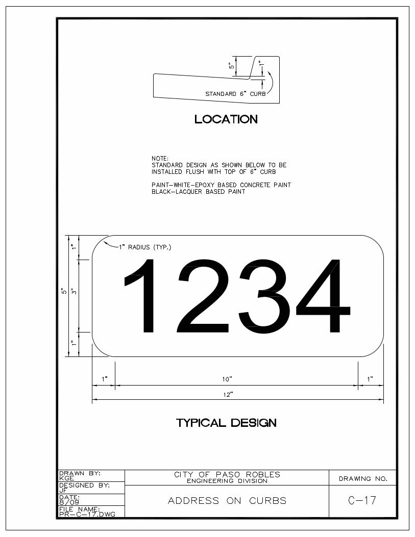
C – Street Improvement DetailsCurb and Gutter ......................................................................................................... C-1“A” Curb .................................................................................................................... C-2Sidewalks ................................................................................................................... C-3Sidewalks with Tree Wells ......................................................................................... C-4Alley Approach ........................................................................................................... C-5Cross-Gutter............................................................................................................... C-6Pavement Replacement............................................................................................. C-7ADA Curb Ramps ..................................................................................................... C-8.1, C-8.2Driveways................................................................................................................... C-9Driveway Locations .................................................................................................... C-10Curb Extensions......................................................................................................... C-11Bus Turnouts.............................................................................................................. C-12Recreation Paths ....................................................................................................... C-13Survey Monuments .................................................................................................... C-14Street Name Sign and Stop Sign............................................................................... C-15Wood Beam Barricade............................................................................................... C-16Address on Curbs ...................................................................................................... C-17
D – Storm Water ControlDrainage Inlet............................................................................................................. D-1Storm Drain Manhole ................................................................................................. D-2
iv
SECTION VIII – STANDARD DRAWING INDEX, Continued
DRAWING DESCRIPTION DRAWING NO.
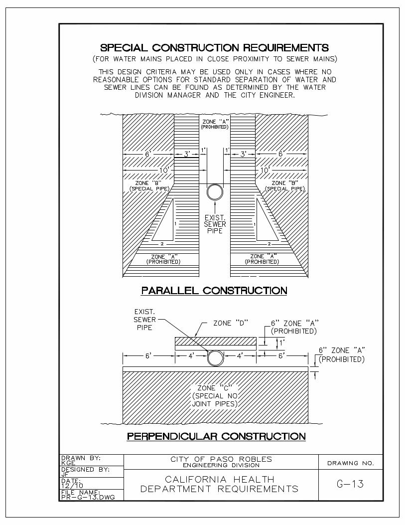
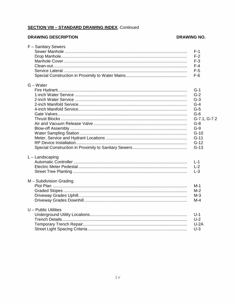
F – Sanitary SewersSewer Manhole .......................................................................................................... F-1Drop Manhole............................................................................................................. F-2Manhole Cover........................................................................................................... F-3Clean-out.................................................................................................................... F-4Service Lateral ........................................................................................................... F-5Special Construction in Proximity to Water Mains..................................................... F-6
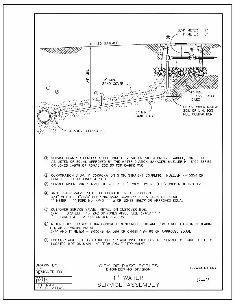
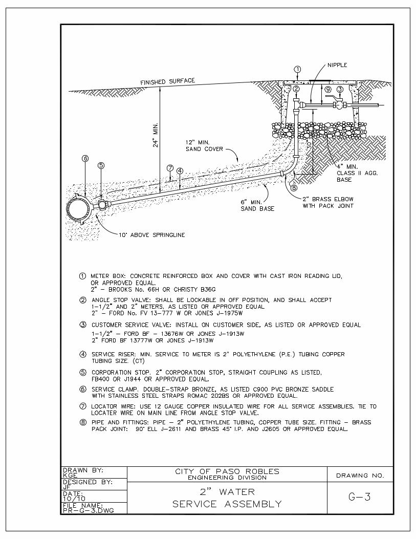
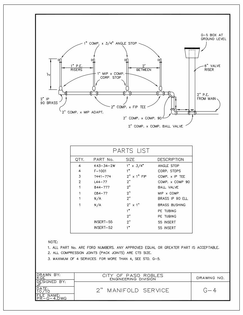
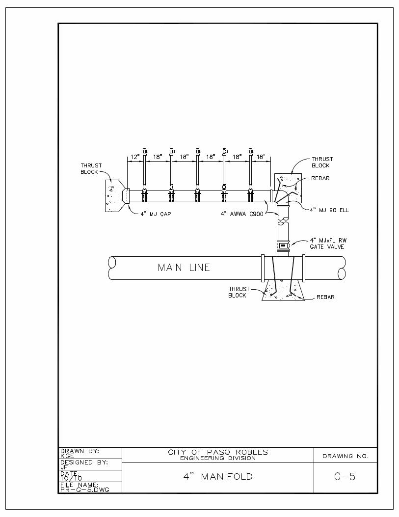
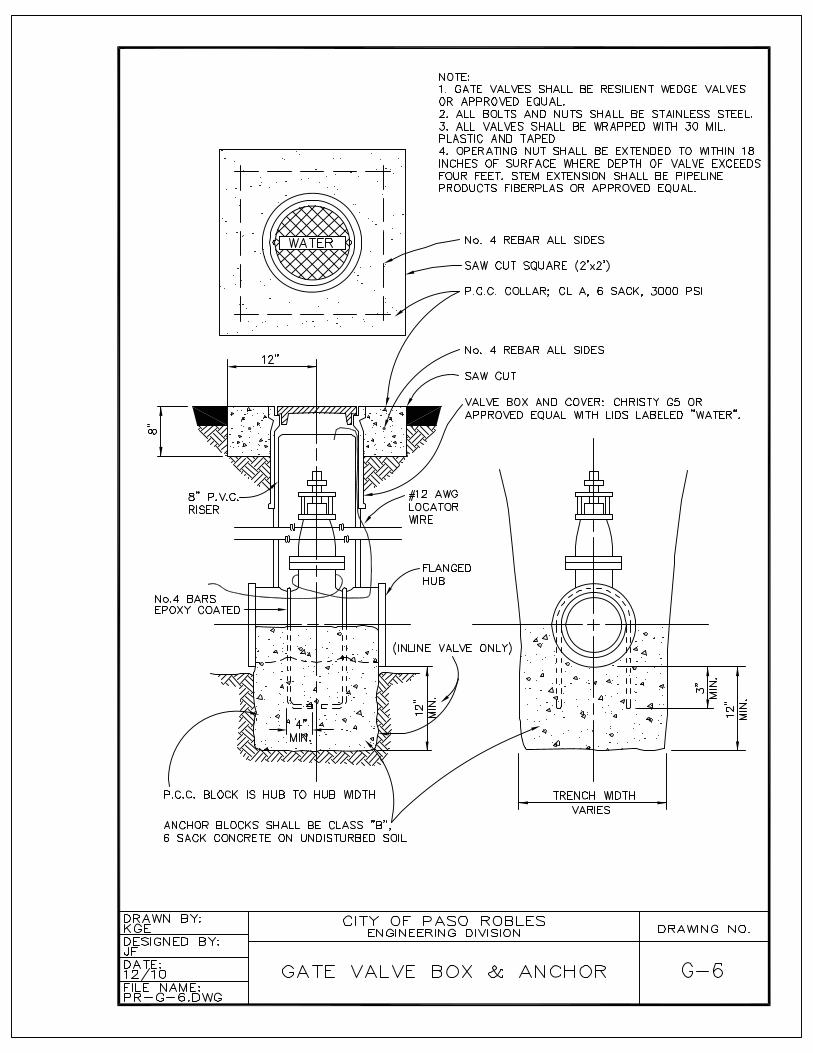
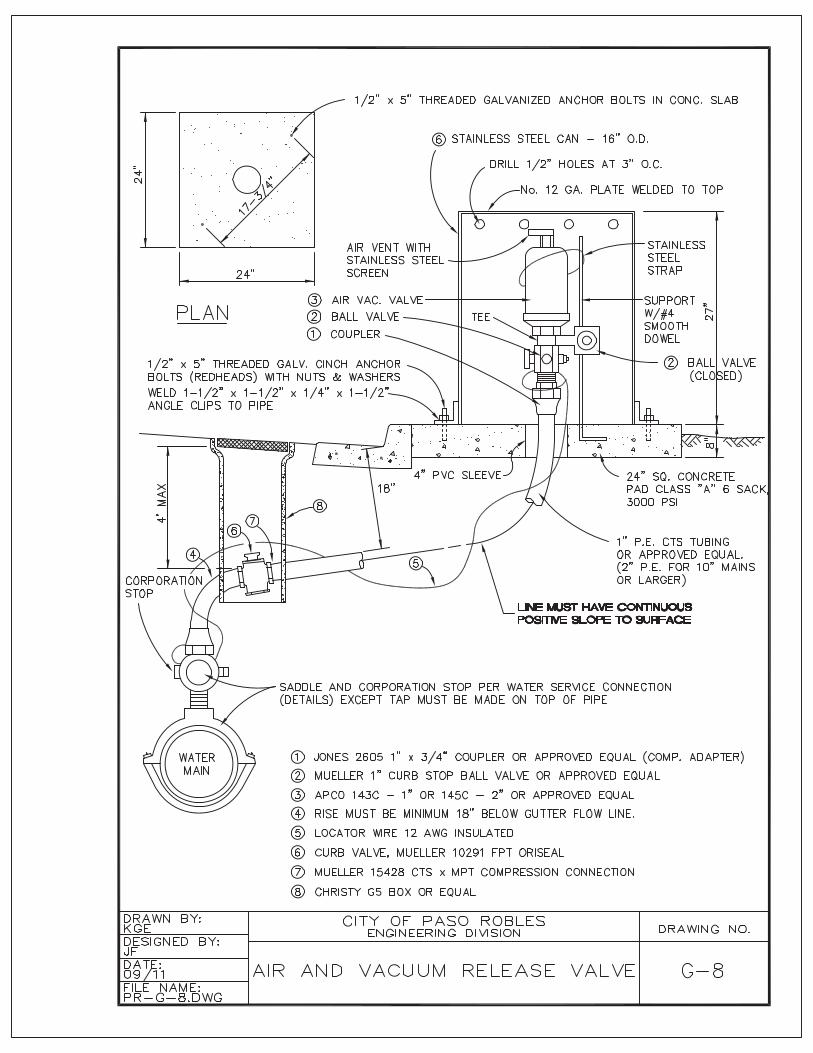
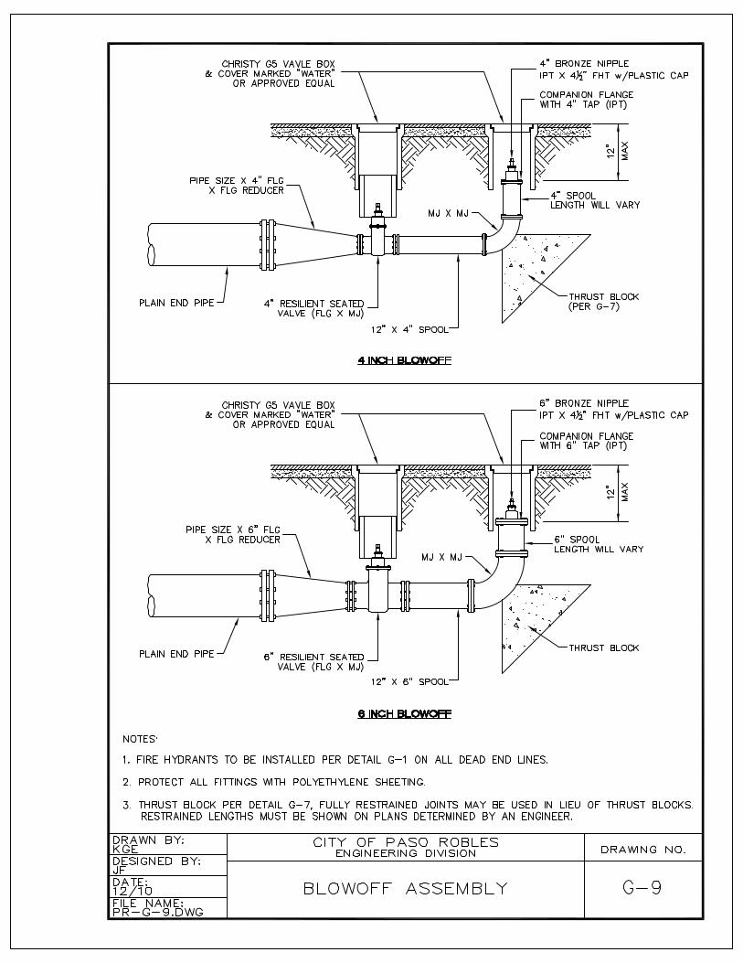
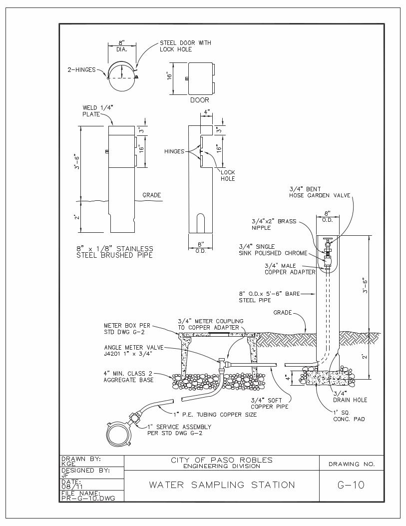
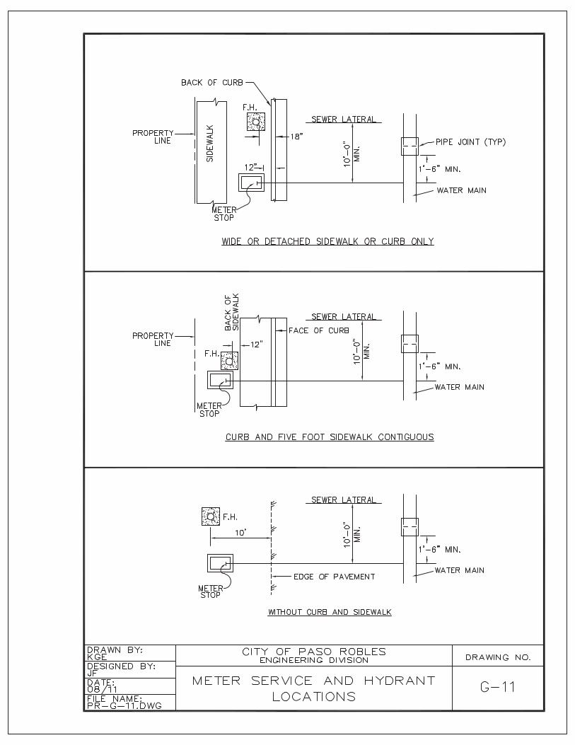
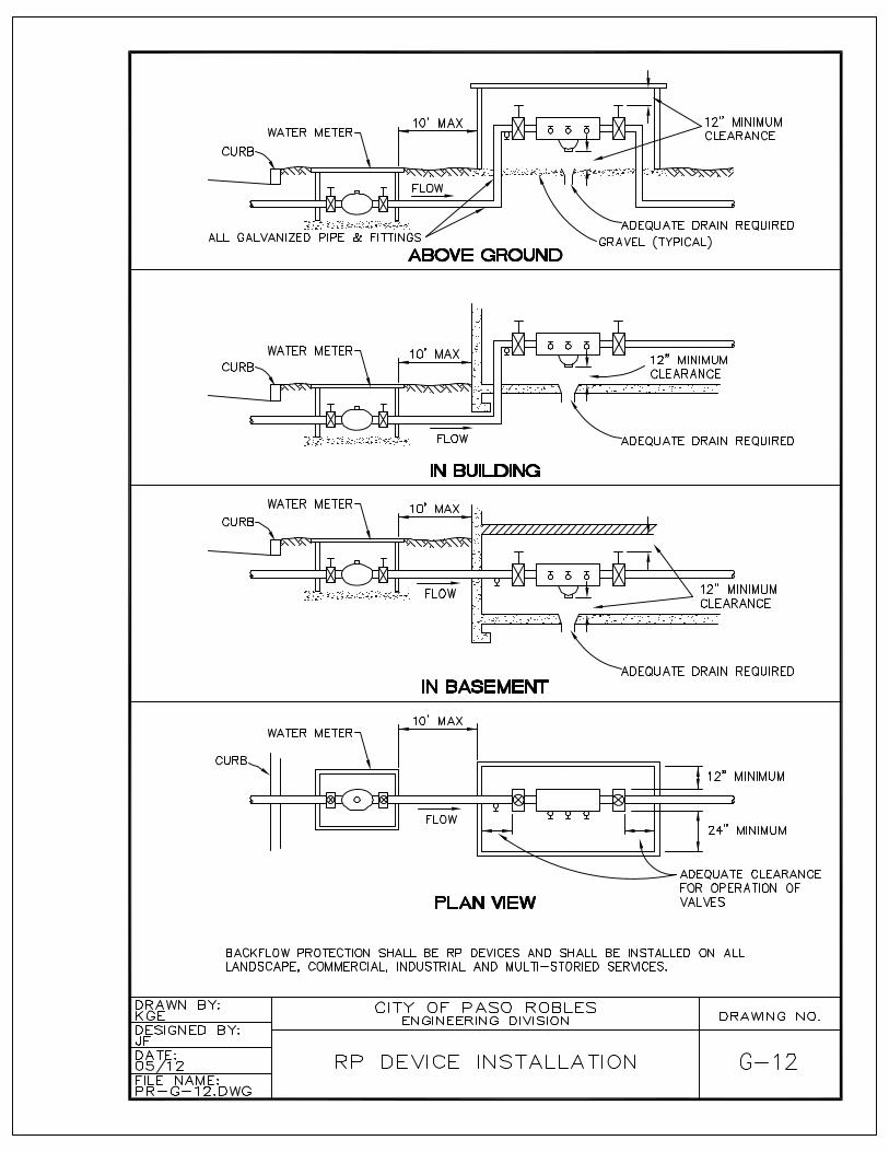
G – WaterFire Hydrant................................................................................................................ G-11-inch Water Service ................................................................................................. G-22-inch Water Service ................................................................................................. G-32-inch Manifold Service.............................................................................................. G-44-inch Manifold Service.............................................................................................. G-5Gate Valves................................................................................................................ G-6Thrust Blocks ............................................................................................................. G-7.1, G-7.2Air and Vacuum Release Valve ................................................................................. G-8Blow-off Assembly ..................................................................................................... G-9Water Sampling Station ............................................................................................. G-10Meter, Service and Hydrant Locations ...................................................................... G-11RP Device Installation................................................................................................ G-12Special Construction in Proximity to Sanitary Sewers............................................... G-13
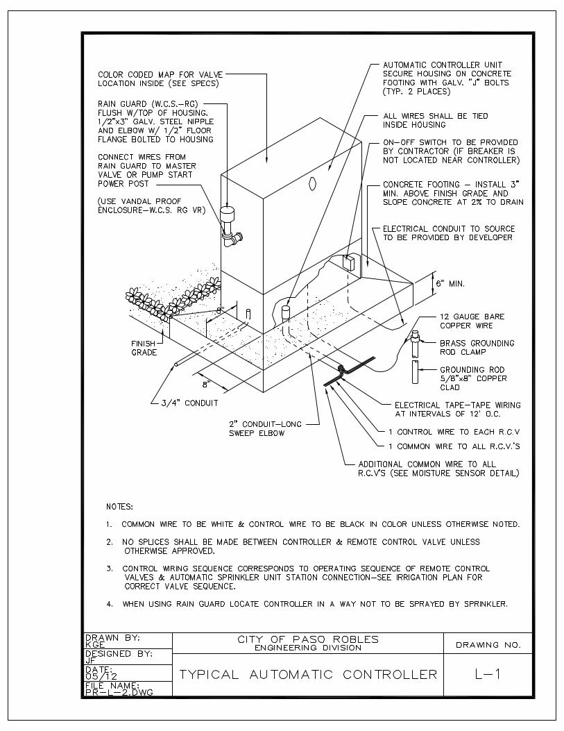
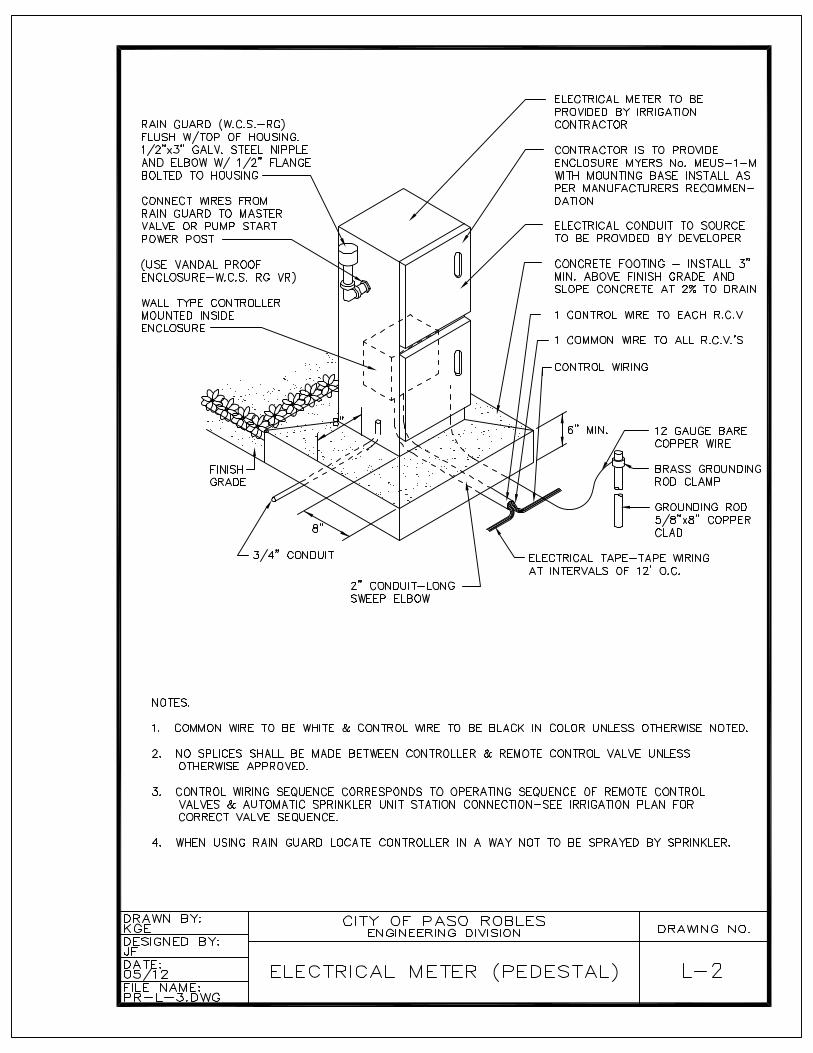
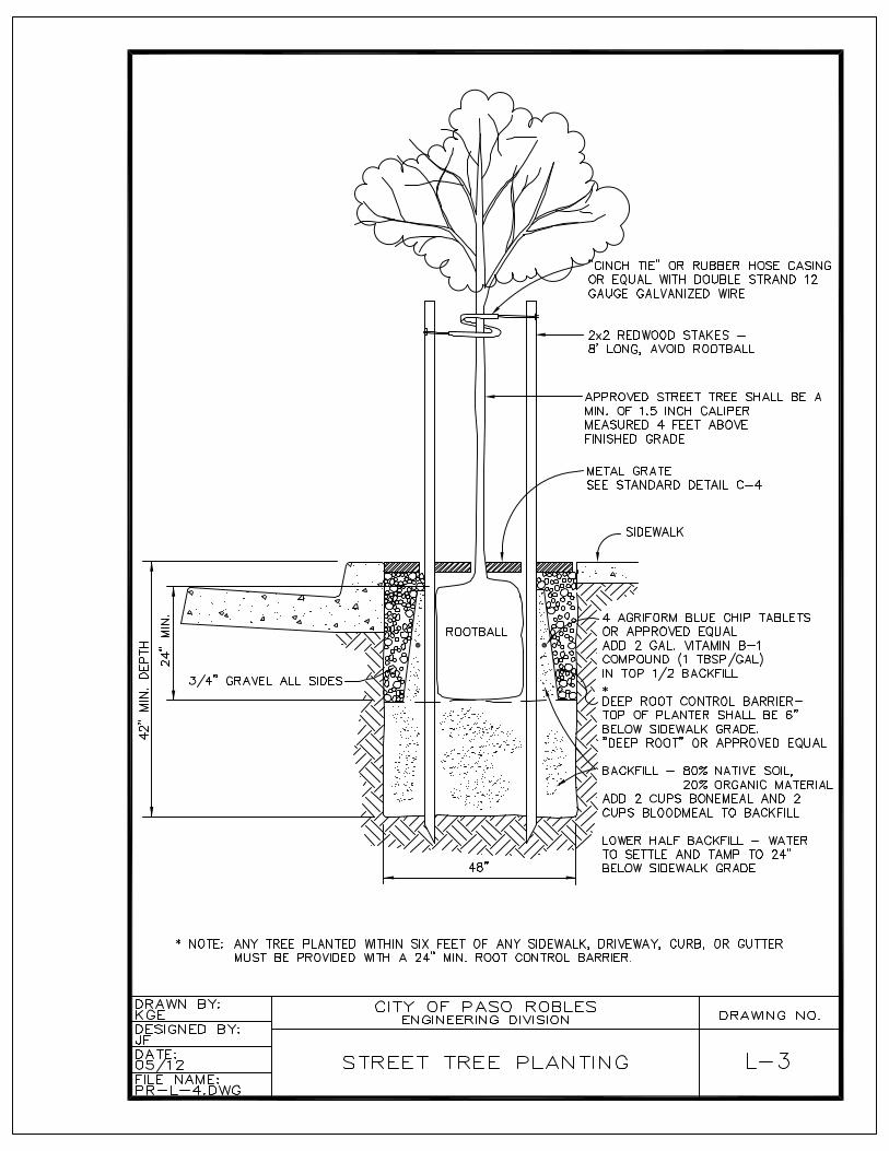
L – LandscapingAutomatic Controller .................................................................................................. L-1Electric Meter Pedestal .............................................................................................. L-2Street Tree Planting ................................................................................................... L-3
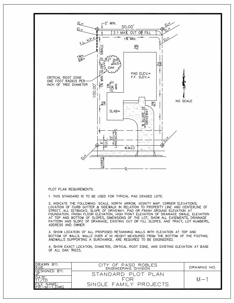
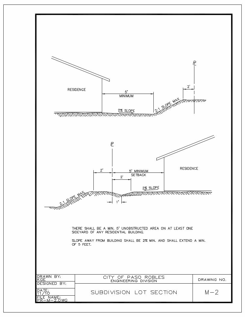
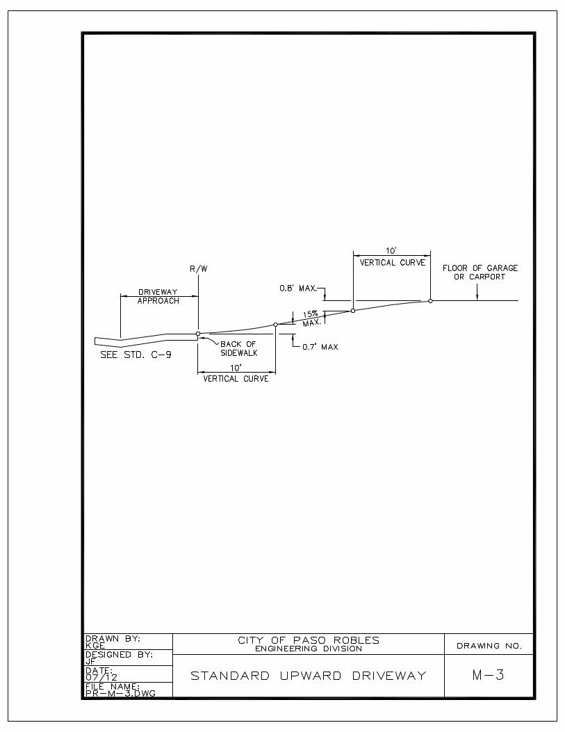
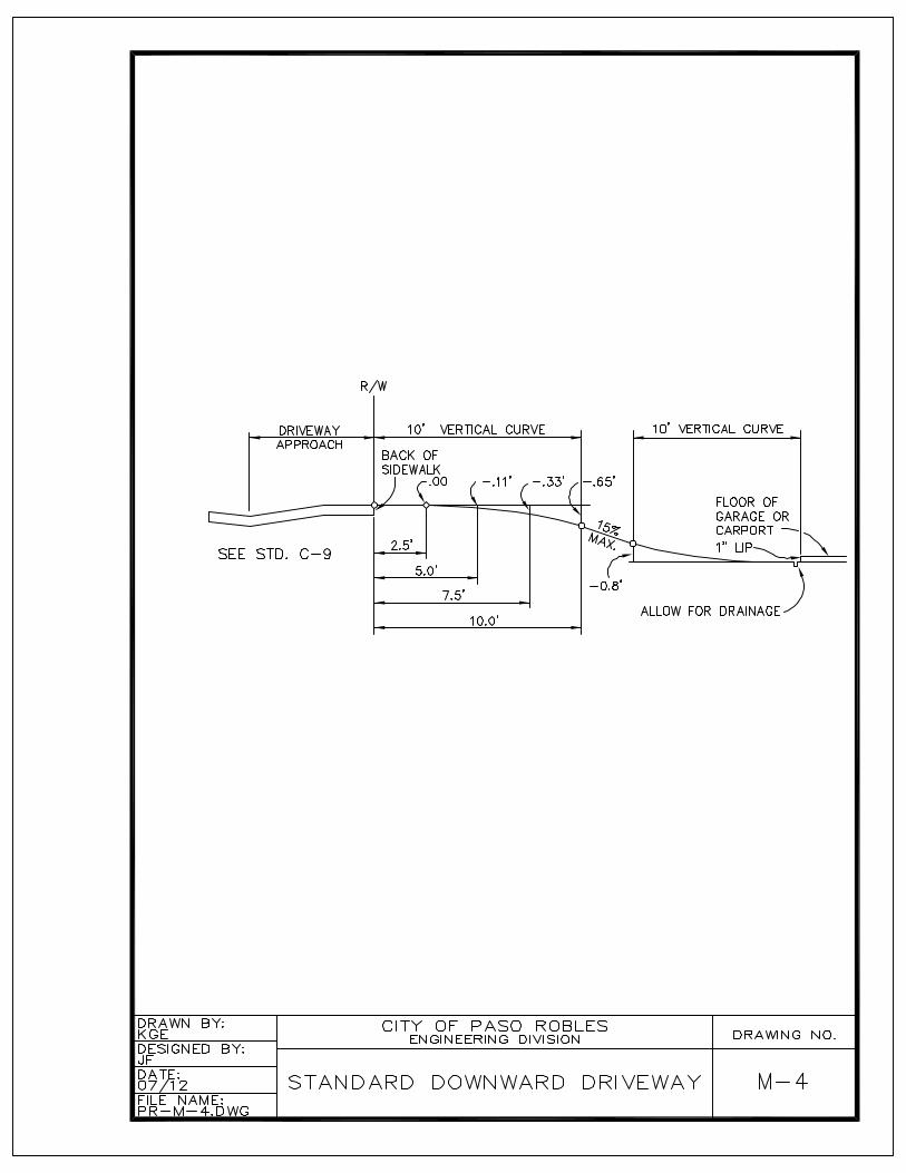
M – Subdivision GradingPlot Plan .................................................................................................................... M-1Graded Slopes ........................................................................................................... M-2Driveway Grades Uphill.............................................................................................. M-3Driveway Grades Downhill ......................................................................................... M-4
U – Public UtilitiesUnderground Utility Locations.................................................................................... U-1Trench Details ............................................................................................................ U-2Temporary Trench Repair.......................................................................................... U-2AStreet Light Spacing Criteria ...................................................................................... U-3
STANDARD SPECIFICATION AND DETAILS
CITY OF EL PASO DE ROBLES
SECTION I
GENERAL REQUIREMENTS
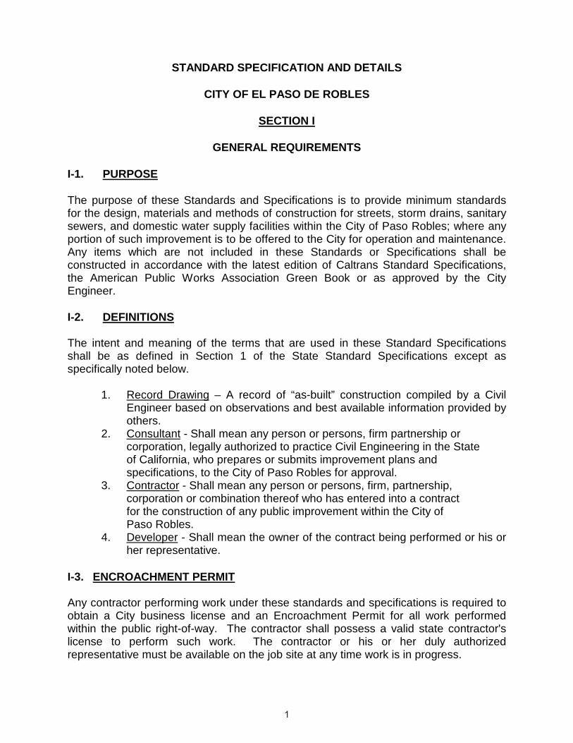
I-1. PURPOSE
The purpose of these Standards and Specifications is to provide minimum standards for the design, materials and methods of construction for streets, storm drains, sanitary sewers, and domestic water supply facilities within the City of Paso Robles; where any portion of such improvement is to be offered to the City for operation and maintenance. Any items which are not included in these Standards or Specifications shall be constructed in accordance with the latest edition of Caltrans Standard Specifications,the American Public Works Association Green Book or as approved by the City Engineer.
I-2. DEFINITIONS
The intent and meaning of the terms that are used in these Standard Specifications shall be as defined in Section 1 of the State Standard Specifications except asspecifically noted below.
1. Record Drawing – A record of “as-built” construction compiled by a Civil Engineer based on observations and best available information provided by others.
2. Consultant - Shall mean any person or persons, firm partnership or corporation, legally authorized to practice Civil Engineering in the State of California, who prepares or submits improvement plans and specifications, to the City of Paso Robles for approval.
3. Contractor - Shall mean any person or persons, firm, partnership, corporation or combination thereof who has entered into a contract
for the construction of any public improvement within the City ofPaso Robles.
4. Developer - Shall mean the owner of the contract being performed or his or her representative.
I-3. ENCROACHMENT PERMIT
Any contractor performing work under these standards and specifications is required to obtain a City business license and an Encroachment Permit for all work performed within the public right-of-way. The contractor shall possess a valid state contractor'slicense to perform such work. The contractor or his or her duly authorized representative must be available on the job site at any time work is in progress.
SECTION II
PREPARATION OF PLANS
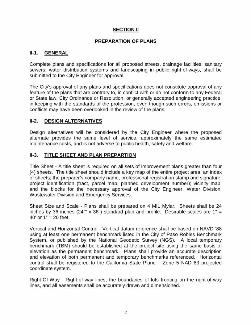
II-1. GENERAL
Complete plans and specifications for all proposed streets, drainage facilities, sanitary sewers, water distribution systems and landscaping in public right-of-ways, shall besubmitted to the City Engineer for approval.
The City's approval of any plans and specifications does not constitute approval of any feature of the plans that are contrary to, in conflict with or do not conform to any Federal or State law, City Ordinance or Resolution, or generally accepted engineering practice, in keeping with the standards of the profession, even though such errors, omissions or conflicts may have been overlooked in the review of the plans.
II-2. DESIGN ALTERNATIVES
Design alternatives will be considered by the City Engineer where the proposed alternate provides the same level of service, approximately the same estimated maintenance costs, and is not adverse to public health, safety and welfare.
II-3. TITLE SHEET AND PLAN PREPARTION
Title Sheet - A title sheet is required on all sets of improvement plans greater than four (4) sheets. The title sheet should include a key map of the entire project area; an index of sheets; the preparer’s company name, professional registration stamp and signature;project identification (tract, parcel map, planned development number); vicinity map; and the blocks for the necessary approval of the City Engineer, Water Division, Wastewater Division and Emergency Services.
Sheet Size and Scale - Plans shall be prepared on 4 MIL Mylar. Sheets shall be 24inches by 36 inches (24”" x 36") standard plan and profile. Desirable scales are 1" = 40' or 1” = 20 feet.
Vertical and Horizontal Control - Vertical datum reference shall be based on NAVD ’88 using at least one permanent benchmark listed in the City of Paso Robles Benchmark System, or published by the National Geodetic Survey (NGS). A local temporary benchmark (TBM) should be established at the project site using the same basis of elevation as the permanent benchmark. Plans shall provide an accurate description and elevation of both permanent and temporary benchmarks referenced. Horizontal control shall be registered to the California State Plane – Zone 5 NAD 83 projected coordinate system.
Right-Of-Way - Right-of-way lines, the boundaries of lots fronting on the right-of-way lines, and all easements shall be accurately drawn and dimensioned.

Stationing and Orientation - The stationing on plan and profile sheets should read from left to right. When a previously designed project within or immediately adjacent to the new project is used as basis of design, plans should use the same stationing of the previous plan or provide an equation to said previous stationing. As practical, the plans should be arranged so that the north arrow is either pointed toward the top or to theright edge of the sheet. Lettering and dimensions should typically be read from the bottom or right margins.
Existing Features - All pertinent topographic features which may affect the design, construction, and operation of the improvement shall be shown on the plans including but not limited to the following: existing curbs, sidewalks, paving edges, utility structures, vaults, poles, underground utility lines, buildings, fences, trees and all other features on or adjacent to the project.
II-4. GRADING PLANS
Grading plans shall typically include the following:
Existing topography including property boundaries, easements, paving edges, curbs, utility poles, vaults, and boxes, buildings, trees, and the boundaries of any 100-year floodplain. The topography shall extend onto surrounding properties. In accordance with the City’s oak tree ordinance, the exact location, trunk diameter (4 inches or larger), drip line and critical root zone of all Oak trees must be accurately identified.
Cross-sections between the property subject to development and adjoining properties.
Pad elevations, street elevations, typical lot grading sections and typical cross-sections between subdivision lots.
Volumes of earthwork including cubic yards of cut, fill, over-excavation and backfill, export and import.
II-5. COMPOSITE UTILITY PLAN
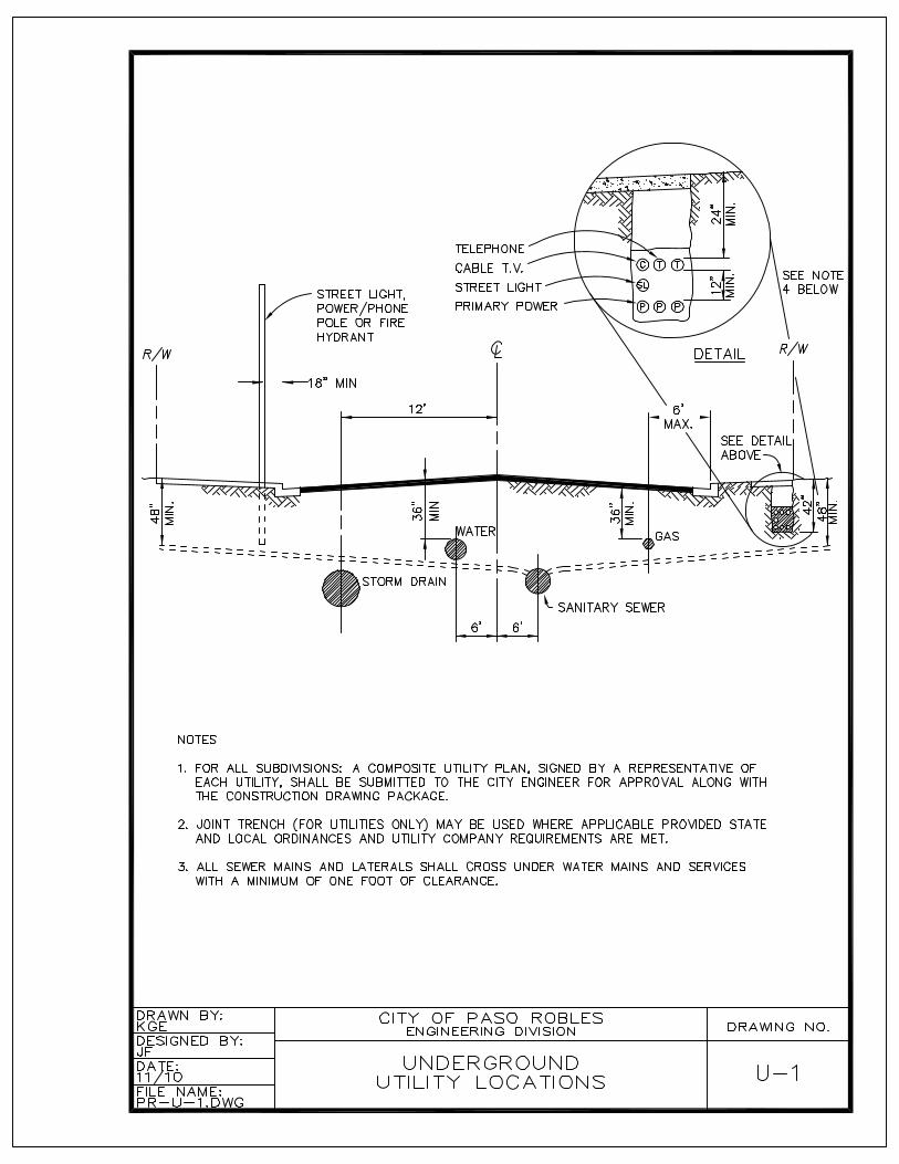
When required by the City Engineer a composite utility plan must be prepared and signed by a representative of each utility company providing power, gas, phone, cable television and internet service. The plan shall show comprehensively all utilities noted above along with water and sewer lines, fire hydrants, street lights, utility vaults, splice boxes and points of service to each subdivision lot.
II-6. STREET IMPROVEMENT PLANS
Street improvement plans shall include the following:
Dedicated right-of-ways, existing and proposed centerline profile, vertical curve data, and curb profiles where they vary from centerline information.
Street dimensions and typical street cross sections including curb, gutter and sidewalk in relation to construction centerline.
Plan view should include all curbs, gutters, cross-gutters and catch basins. The beginning and ends of horizontal curves shall be noted and stationed. Limits of paving shall be clearly indicated. Locations of existing and proposed survey monuments,street name signs, traffic signs and street lights shall be noted.
II-7. UNDERGROUND SEWER, WATER AND STORM DRAIN PLANS
Sewer, water and storm drain designs shall typically be combined on underground utility sheets separate from street improvement design sheets. Underground utility sheets shall include:
Profiles and design grades of sanitary sewer mains, water mains and appurtenances,storm drains and catch basins.
Water distribution plans shall indentify the locations of all services, gate valves, air vacuum release valves, blow-offs and fire hydrants.
Sanitary sewer plans shall indentify the locations of all laterals, manholes and clean-outs.
Plans for storm drains shall include locations of all catch basins, collection devices and manholes. Hydraulic grade-line profiles shall be provided where required by the City Engineer.
II-8. EROSION CONTROL PLANS
Where required, plan sets for public works construction shall include erosion control plans and specification. These plans and specifications shall reference the Storm Water Pollution Prevention Plan and Water Board Enrollment Identification Number.
II-9. RECORD DRAWINGS
During the progress of construction the design engineer shall maintain a record of all significant deviations from the approved plans. Prior to acceptance of the work by the City, the design engineer will provide one copy set of the improvement plans with all record changes noted for approval by the City Engineer. Upon approval of the draft Record Drawing set, the design engineer shall provide to the City Engineer a signed and stamped full size set of Record Drawings on Mylar, an electronic AutoCAD drawing file, and an Acrobat PDF file.
II-10. LANDSCAPE PLANS
Plans for landscaping of all medians, parkways, detention basins, open spaces, or other areas to be maintained by the City, or the Landscape and Lighting District, shall be prepared by a Landscape Architect and shall be submitted as part of the improvement plan set to the City Engineer.
SECTION III
CONSTRUCTION OBSERVATION AND STORM WATER QUALITY MANAGEMENT
III-1. GENERAL
Each phase of improvements, constructed to these specifications must be observed bythe City Engineer or a representative of the Public Works Director prior to proceeding with subsequent phases.
The City will observe, as considered necessary, the construction of public improvements required as a condition of approval of any land development or entitlement. Improvements constructed without observation or approval as provided above, or constructed contrary to the direction of the City’s representative, will not be accepted.
III-2. ACCEPTANCE OF IMPROVEMENTS
At the completion of construction, the design engineer shall submit the following items to the City Engineer:
1) Engineer's Improvement Certification 2) Soil Testing Reports 3) Material Compliance Reports 4) Record Drawings 5) Other documentation that may be required by the City Engineer to
determine satisfactory completion of the project.
All improvements constructed in public right-of-ways established by subdivision maps must be formally accepted by the City Council.
III-3. STORM WATER QUALITY BEST MANAGEMENT PRACTICES
B. Water Quality
1.1 Purpose
The purpose of these requirements is to prevent the pollution of storm water runoff and non-storm water discharges from construction projects by keeping pollution out of the storm water system, reducing the exposure and discharge of materials and wastes to storm water system, and by reducing erosion and sedimentation. The contractor shall eliminate or minimize non-storm water discharges from the construction site to storm drains, natural outlets, channels, creeks or other waterways. All construction activities shall be performed in a manner that minimizes, to the maximum extent practicable, any pollutants entering directly or indirectly the storm water system, natural waterways or ground water.
1.2 NPDES Permits
State General Permit for Storm Water Discharges Associated with Construction Activity This permit is required for any construction activity that disturbs one or more acres of soil or disturbs less than one acre but is part of a larger common plan of development that in totals disturbs one or more acres. (The City shall file a notice of intent (NOI) requesting permit coverage for City funded projects only.) AWaste Discharge Identification Number (WDID #) must be submitted prior to issuance of a grading permit.
The Contractor shall maintain a copy of a Storm Water Pollution Prevention Plan (SWPPP) prepared in compliance with the State Construction General Permit, on site at all times. The Contractor shall be responsible for implementing, maintaining, and repairing all storm water pollution controls or Best Management Practices described in the SWPPP for the duration of the work. The Contractor shall make any repairs, or amend the SWPPP, if the project engineer or City determines the Contractor is not in compliance with the State Permit.
The project owner will be responsible to the City for any damages to City resulting from failure to make the repairs or properly maintain pollution prevention devices. The Contractor is responsible for submitting an annual compliance certificate to the State Water Board.
Low Threat Discharge PermitA Low Threat Discharge Permit may be required for discharges to a waterway or to the land. The Contractor is responsible for determining if this permit is required.
2.1 Erosion and Sediment Control Plan
All grading permits shall include an Erosion Control Plan approved by the City Engineer.
Construction Site Best Management Practices (BMPs) are applied during construction activities to reduce the pollutants in storm water discharges throughout construction. These Construction Site BMPs provide both temporary erosion and sediment control, as well as control for potential pollutants other than sediment. There are six categories of BMPs suitable for controlling potential pollutants on construction sites. They are: Soil Stabilization Practices;
Sediment Control Practices; Tracking Control Practices;Wind Erosion Control;Non-Stormwater Controls; andWaste Management and Material Pollution Controls.
Effective erosion and sediment control planning relies on a system of BMPs (e.g., mulches for source control, fiber rolls on slopes for reducing runoff velocities, silt fence at the toe of slopes for capturing sediment, etc.).
To meet regulatory requirements and protect the site resources, every project must include an effective combination of erosion and sediment control measures. These measures must be selected from all of the BMP categories presented in this section: soil stabilization practices, sediment control practices, tracking control practices, and wind erosion control practices. Additionally, the project plan must include non-storm water controls, waste management and material pollution controls to comply with the City’s Storm Water Management Plan.
3.1 General Requirements for ALL Projects
1. Non hazardous Material / Waste Managementa. Designated Area – The Contractor shall propose designated areas of
the project site and any staging areas, suitable for material delivery, storage, and waste collection that, to the maximum extent practicable, are near construction entrances and away from catch basins, gutters, drainage courses, and waterways.
b. Granular Material(1) All granular material shall be stored at least ten feet away from
any catch basin and curb returns.(2) Granular material shall not be allowed to enter the storm drains or
waterways.(3) Granular material shall be covered and surrounded with sand
bags or waddles when rain is forecast with 48 hours or during wet weather.
c. Dust Control(1) The Contractor shall comply with Section 20.20.040 of the
Municipal Code which states:A. Windy Conditions: In the event that dust cannot be controlled
due to strong winds and becomes a nuisance, the City Engineer may order the work to be halted for the day.
B. Dust Control: All graded surfaces and materials shall be wetted, treated or contained in such a manner as to prevent dust from leaving the site.
C. Completion of Grading: The graded site shall be thoroughly wetted in order to form a crust over the exposed dirt surfaces. Further applications or other methods acceptable to the City Engineer may be necessary if the site is disturbed.
d. Street Sweeping(1) At the conclusion of each working day the Contractor shall clean
and sweep all roadways and on-site paved areas. The Contractor
shall not use water to flush down streets in place of street sweeping.
e. Recycling(1) All construction refuse (i.e. concrete, asphalt, wood, gypsum
board, etc.) shall be separated and removed from the project to a recycling facility.
f. Disposal(1) At the end of each working day, all scrap, debris and waste
material shall be collected, and disposed of properly.(2) All dumpsters shall be inspected for leaks and repaired or
replaced as necessary.(3) No water shall be discharged on-site from cleaning dumpsters.(4) Regular waste collection shall be arranged to prevent dumpsters
from overflow.
2. Hazardous Material / Waste Managementa. Storage
(1) All hazardous materials, such as pesticides, paint, thinners, solvents, and fuels; and all hazardous wastes, such as waste oil and antifreeze; shall be labeled and stored in accordance with all local, State and Federal regulations.
(2) All hazardous materials and all hazardous wastes shall be stored in accordance with secondary containment regulations, and it is recommended that these materials and wastes be covered, as needed to avoid potential management of collected rain water as a hazardous waste.
(3) The Contractor shall keep an accurate, up-to-date inventory, including Material Safety Data Sheets (MSDSs), of hazardous materials and hazardous wastes stored on-site, to assist emergency response personnel in the event of a hazardous materials incident.
b. Usage(1) When rain is forecast within 48 hours or during wet weather, the
Engineer may prevent the Contractor from applying chemicals in outside areas.
(2) Pesticides or fertilizers shall not be over-applied and shall follow material manufacturer’s instructions regarding uses, protective equipment, ventilation, flammability, and mixing of chemicals.
c. Disposal(1) Regular hazardous waste collection shall be arranged to comply
with time limits on storage of hazardous wastes. (2) Hazardous waste shall be disposed of only at authorized and
permitted treatment, storage, and disposal facilities. Only licensed hazardous waste haulers shall be employed to remove wastes off-site.
3. Spill Prevention and Controla. A stockpile of spill cleanup materials, such as rags or absorbents, shall
be kept readily accessible on-site.b. The Contractor shall immediately contain and prevent leaks and spills
from entering any storm drains or waterways and properly clean up and dispose of the waste and cleanup materials. If the waste is hazardous, the Contractor shall handle the waste as described in section 2 (c) above.
c. Spilled materials shall not be washed into streets, gutters, storm drains, or waterways nor be covered with other site materials.
d. Any hazardous materials spills shall be reported to the Engineer.
4. Vehicle / Equipment Cleaninga. Vehicle or equipment cleaning shall not be performed on-site, in any
staging area or in the street using soaps, solvents, degreasers, steam cleaning equipment, or equivalent methods.
b. Vehicle or equipment cleaning shall be performed with water only, in a designated, bermed area that will not allow rinse water to run off-site or into streets, gutters, storm drains, or waterways.
5. Vehicle / Equipment Maintenance and Fuelinga. Maintenance and fueling of vehicles or equipment shall be performed
in a designated, bermed area or over a drip pan that will not allow run-on of storm water or runoff of spills.
b. Secondary containment shall be used, such as a drip pan, to catch leaks or spills any time that vehicle or equipment fluids are dispensed, changed, or poured.
c. A stockpile of spill cleanup materials shall be kept, such as rags or absorbents, readily accessible on-site.
d. Leaks and spills of vehicle or equipment fluids shall be cleaned up immediately and hazardous waste shall be disposed of, as described in section 2.c above.
e. The Contractor shall not wash any spilled material into streets, gutters, storm drains, or waterways and shall not bury spelled hazardous materials.
f. Any hazardous materials spill shall be reported to the City.g. All vehicles and equipment arriving on-site shall be inspected for
leaking fluids and shall be promptly repaired as needed. Drip pans shall be used to catch leaks until repairs are made.
h. Waste oil and antifreeze shall be recycled, to the maximum extent practicable.
i. The Contractor shall comply with Federal, State, and City requirements for aboveground storage tanks.
6. Sanitary/Septic Waste Managementa. Sanitary/septic waste management practices shall be implemented on
all sites that use temporary or portable sanitary/septic waste systems.b. Sanitary facilities shall be located away from drainage facilities,
watercourses, and from traffic circulation. When subjected to high winds, temporary sanitary facilities shall be secured to prevent overturning.
c. The contractor shall ensure that sanitary/septic facilities are maintained in good working order by a licensed service.
d. Only licensed sanitary/septic waste haulers shall be used. Waste must be disposed at a permitted facility only.
7. Contractor Training and Awarenessa. All employees / subcontractors shall be trained on the storm water
pollution prevention requirements contained in these Specifications.b. Subcontractors shall be informed of the storm water pollution
prevention contract requirements and include appropriate subcontract provisions to ensure that these requirements are met.
c. Warning signs shall be posted in areas treated with chemicals.
3.2 Activity-Specific Requirements for ALL Projects
1. Dewatering Operationsa. Discharge Permits
(1) The Contractor shall ensure that appropriate NPDES permits are obtained from the State Water Resources Control Board for discharges to land or waterways.
(2) The Contractor shall obtain a Temporary Discharge Permit prior to discharging to the City’s sewer system. Discharges to the City sewer are required to meet the local discharge limits in Sections 14.10.40 and 14.10.60 of Chapter 14.10 of the City Municipal Code.
b. Sediment Control(1) Water shall be routed through a control measure, such as a
sediment trap, sediment basin, or Baker tank to remove settleable solids prior to discharge.
(2) Approval of the control measure shall be obtained in advance from the RWQCB for discharges to a waterway or from the Industrial Waste Manager for discharges to the sewer.
(3) Filtration of the water following the control measure may be required on a case-by-case basis.
(4) Water shall be reused for other needs, such as dust control or irrigation, to the maximum extent practicable.
c. Contaminated Groundwater(1) If the project is within an area of known groundwater
contamination, then water from dewatering operations shall be
tested to determine if contaminants are present. If the groundwater is contaminated, it must be treated to meet discharge permit requirements or hauled off-site for proper disposal.
2. Paving Operationsa. Project site Management
(1) The Contractor shall protect drainage courses by using control measures, such as earth dike, waddles, and sand bags, to divert runoff or trap and filter sediment.
(2) Catch basins and manholes shall be covered when paving or applying seal coat, tack coat, slurry seal, or fog seal.
(3) Paving equipment shall be managed when not in use to prevent spills or leaks.
b. Paving Waste Management(1) Excess sand placed as part of a sand seal or to absorb excess oil
shall not be swept or washed down into gutters, storm drains, or waterways. Instead, the Contractor shall either, collect the sand and return it to the stockpile, or dispose of it in a trash container. Water shall not be used to wash down fresh asphalt concrete pavement.
3. Saw Cuttinga. During saw cutting, catch basins shall covered or barricaded using
control measures, such as filter fabric, waddles, sand bags, and fine gravel dams, to keep slurry out of the storm drain system.
b. Saw cutting slurry shall be vacuumed up at the same time the cutting is occurring. The dust and slurry shall be removed from the site by vacuuming and not washed or dumped into City sewer or storm drains or left to sit in the street or gutters. Alternate methods of removal shall be approved in writing by the Engineer prior to implementation by the Contractor.
c. If saw cut slurry enters catch basins, the Contractor shall remove the slurry from the storm drain system immediately.
4. Contaminated Soil Managementa. On all projects involving grading or excavation, the Contractor shall
look for contaminated soil as evidence by site history, discoloration, odor, differences in soil properties, abandoned underground tanks or pipes, or buried debris.
b. If the project is within an area of known soil contamination or evidence of soil contamination is found, then soil from grading or excavation operations shall be tested. The soil shall be managed as required by State or Federal laws.
5. Concrete, Grout, and Mortar Waste Managementa. Management – Concrete, grout, and mortar shall be stored away from
drainage areas to ensure that these materials do not enter the storm drain system or waterways.
b. Concrete Truck / Equipment Wash Out(1) Concrete trucks or equipment shall not be washed out into streets,
gutters, storm drains, or waterways.(2) Washout of concrete trucks or equipment shall be performed off-
site or in a designated area on-site where the water will flow into dirt or into a temporary pit in a dirt area. The water shall be allowedto percolate into the soil and dispose of the hardened concrete in a trash container. If a suitable dirt area is not available, then the contractor shall collect the wash water and remove it off-site.
6. Earthworka. An Erosion Control Plan approved by the City Engineer must be
submitted with the grading permit application per 2.1 of this section. The control of erosion and sediment shall be maximized by using the BMPs for erosion and sedimentation. The Caltrans Construction Site Best Management Practices Manual can be used as a reference.
7. Stockpilesa. Procedures and practices shall be implemented to reduce or eliminate
pollution of storm water from stockpiles of soil, and paving materials Portland cement concrete (PCC), rubble, asphalt concrete (AC), asphalt concrete rubble, aggregate base, aggregate sub-base or pre mixed aggregate and asphalt binder.
b. Stockpiles shall be protected year-round from runoff and blowing dust.c. Stockpiles shall be located away from concentrated flows of storm
water, drainage courses, and drain inlets.d. During the rainy season, soil stockpiles shall be covered or protected
with a temporary perimeter sediment barrier prior to the onset of precipitation.
e. Stockpiles of cold mix shall be placed on and covered with plastic or comparable material prior to the onset of precipitation.
SECTION IV
STREETS
IV-1. DESIGN GUIDELINES
The Circulation Element of the General Plan establishes certain key City streets as Arterials. These streets are identified further as four lane, three lane or two lane arterials. Streets not designated Arterial are established as Local. Their specifications may vary depending on their location within specific plans, rural areas and/or hillside terrain.
Typical right-of-way widths are established in these Standard Details andSpecifications. Variations to these standards may occur due to topography, City limits, or other constraints. These variations will be considered on a case by case basis.
A. Classes of Streets
Arterial Streets may be designed with either two or four lanes. Typical designs include landscape medians, separate lanes for turning movements, Class II bike lanes, and pedestrian paths separated by landscaped parkways. Standard Details A-1 through A–3 provide examples.
Local streets provide direct access to all parcels in the City. Standard Detail No. A-4 is typical, however, many local street standards are established by specific plans and alternative details where modified by topography, right-of-way or other constraints.
Industrial Streets may be wider to accommodate larger vehicles. However, street design in employment centers must reflect the need for pedestrian and bike access so that these alternative modes of travel are available and attractive to employees. Standard Drawing No. A-5 is typical.
Details for West side streets shown on the 1889 map of El Paso De Robles are found in the Town Centre and Uptown Specific Plans. Those details are incorporated herein by reference.
B. Geometrics and Profiles
Where feasible, the minimum grade on new streets shall be one percent (1%).Portions of streets may be designed with a minimum grade of 0.50 percent where topographic constraints warrant.
Local streets may be designed with a maximum grade of up to 15 percent. The maximum grade on new arterial streets should be limited to eight percent (8%)subject to topographic constraints.
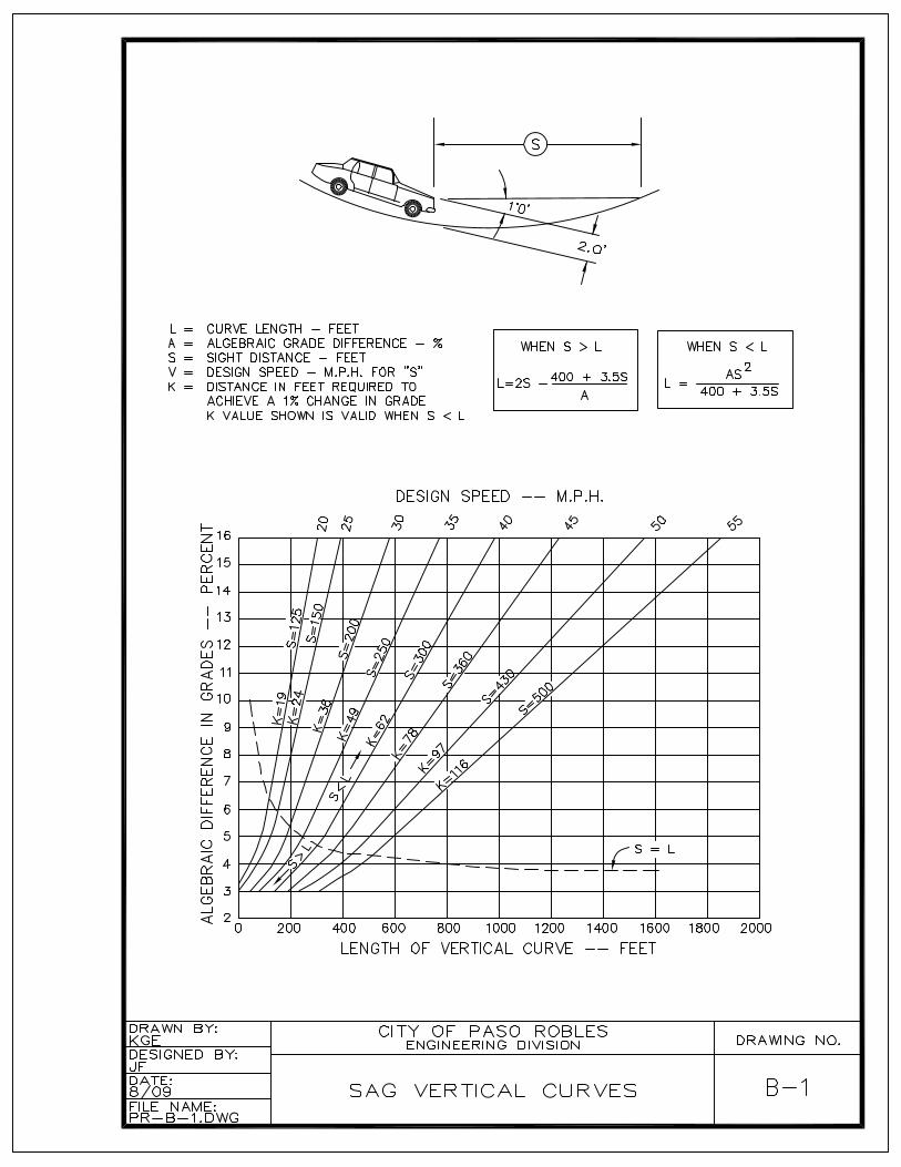
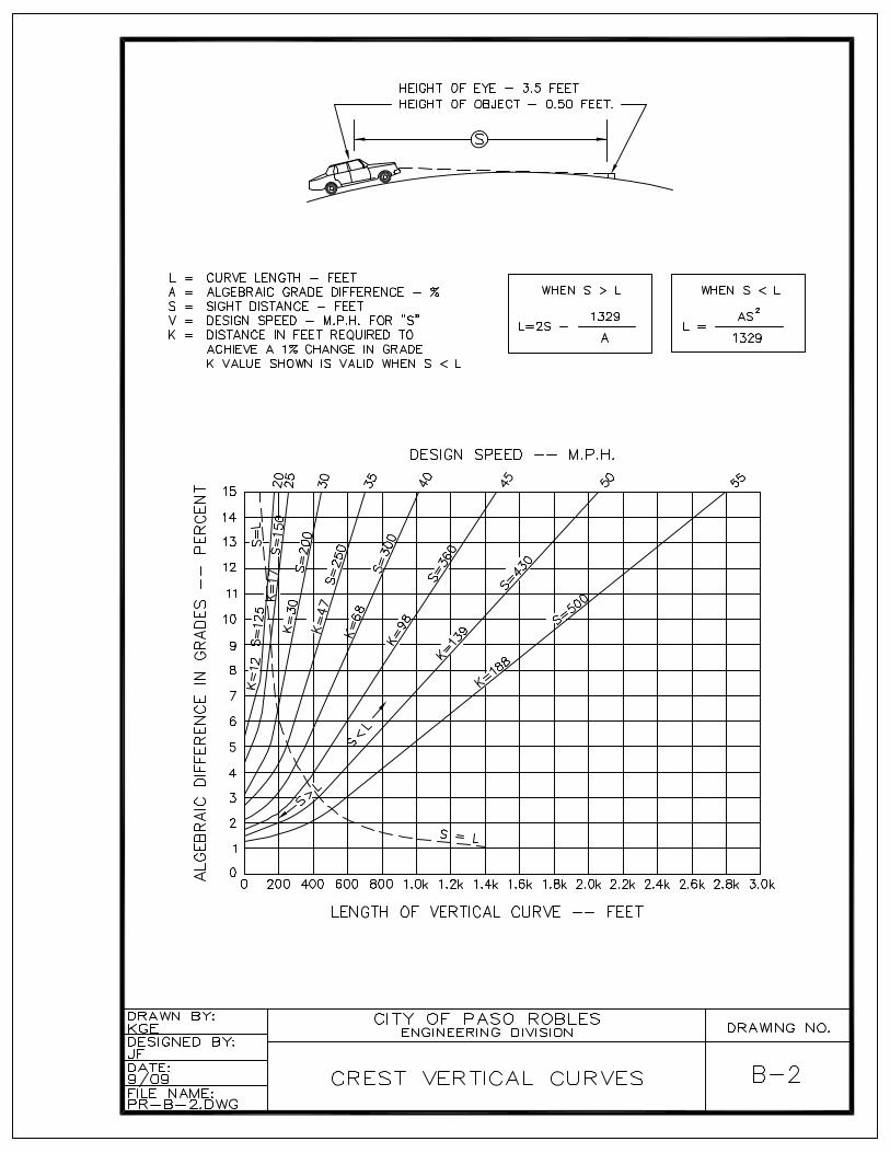
Vertical curves shall be designed in accordance with design speed and grade difference criteria as outlined in "A Policy on Geometric Design Of Urban Highways", published by the American Association of State Highway and Traffic Officials, latest edition (See Standard Details B-1 and B-2). For visibility and safety minimum design speeds shall be 35 miles per hour for arterial streets and25 mph for local streets.
Traffic calming features are encouraged in the design of all new streets.
When two streets intersect, neither street shall have a grade greater than three percent (3%) for a minimum distance of 20 feet measured from the curb line of the intersected street. Standard Detail B-3 provides profile information for use inhillside terrain.
Curb return radii may vary from 10 to 30 feet depending upon the width of the streets being accessed. Smaller radii are preferred; however, accommodations must be made for emergency services (and other large vehicles depending upon projected land uses).
C. Survey Monuments
Survey monuments shall be shown on the plans in accordance with the final subdivision map and Standard Detail C-14. Street monuments shall be set at all street centerline intersections and on centerline at the beginning and end of all curves. Existing survey monuments shall be preserved and reset in accordance with Standard Detail C-14 if necessary.
IV-2. MATERIALS
All materials furnished and the methods of performing any proposed work shall be in conformance to the applicable portions of these Standard Details and Specificationsand Caltrans Standard Specifications.
A. Asphalt Concrete
Asphalt Concrete shall conform to the requirements for Type B Asphalt Concrete as specified in Section 39 of Caltrans Standard Specifications utilizing the 3/4 inch maximum aggregate.
B. Aggregate Base
Aggregate base shall be Class II and shall conform to the requirements of Section 26 of Caltrans Standard Specifications. C. Concrete
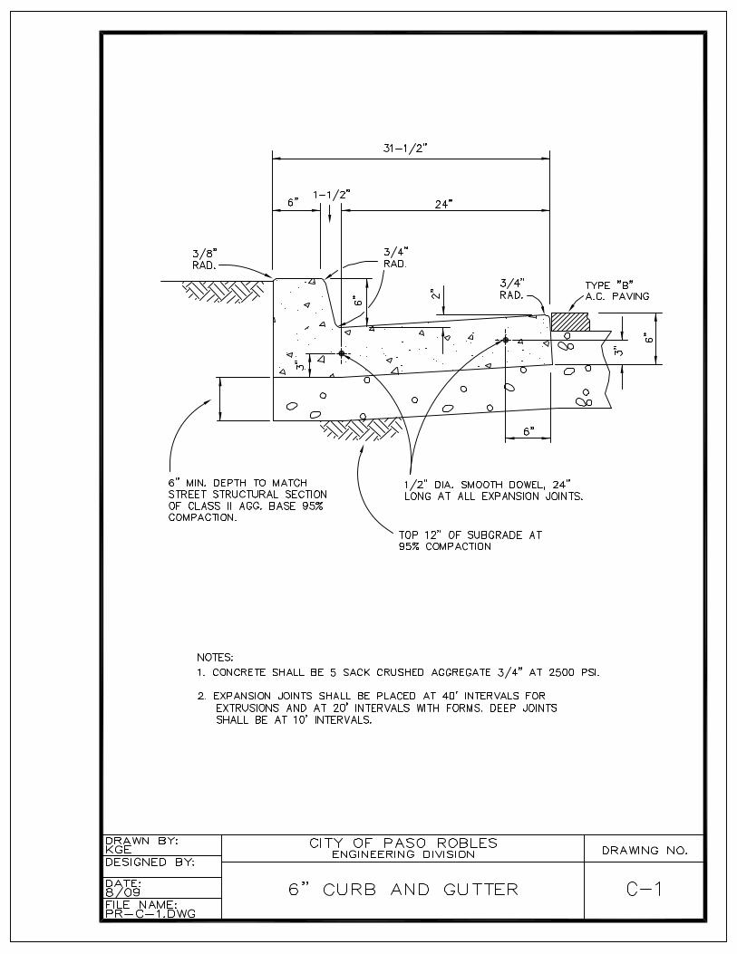
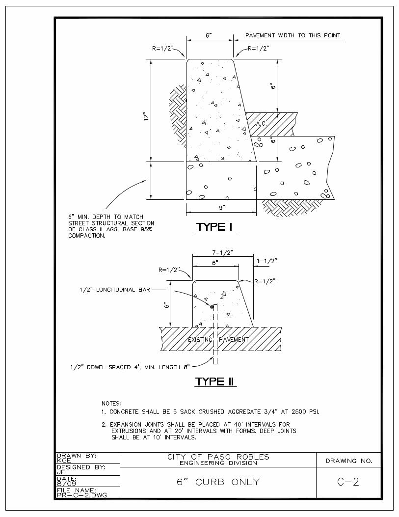
All structures and surfaces subject to vehicle loads shall be shall be constructed with Class A Portland Concrete Cement (PCC), 6 sack, ¾ inch crushed aggregate, 4,000 psi. Curbs and sidewalks may be constructed with Class B PCC, 5 sack, 2,500 psi. See standard details for specifications.
Expansion joints shall be placed with ½ inch material at 20-foot intervals in curbs and sidewalks, at the ends of all returns and transitions, storm drain inlets and driveways.
D. Street Lights
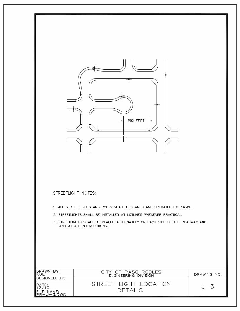
All street light poles, lamps, wiring and circuits shall be installed, owned and operated by P. G. and E. Street light styles must be chosen from a catalog and supplier approved by P. G. and E. Proposed street light styles must be included in all entitlement applications where street improvements will be required. The proposed street light style must be approved by the Planning Commission prior to improvement plan approval.
IV-3. CONSTRUCTION GUIDELINES
Unless otherwise modified in the following or approved by the Engineer, the roadbed shall be prepared and constructed in accordance with the applicable portions ofCaltrans Standard Specifications.
A. Pavement Structure Section
The design of street structural sections shall be determined by Resistance ("R") Value testing of sub-grade and traffic indexes as outlined in the Pavement Management Program adopted by the City Council in 2006. Traffic indexes shall be 8.0 for three and four lane arterial streets and streets subject to heavy truck traffic (industrial areas); 7.0 for two lane arterial streets and 6.0 for all other streets.
Relative compaction tests shall be made on sub-grade, base and asphalt materialplaced within streets as directed by the supervising Geotechnical Engineer.
IV-4 STREETS EXEMPT FROM IMPROVEMENTS, CODE SECTION 11.12.030
With the adoption of these Standard Details and Specifications, the City Council haswaived the requirements for street frontage improvements associated with building permits per Code Section 11.12.030. In lieu fees for construction of sidewalks apply in accordance with the Code.
Orchard Bungalow (with the exception of Shannon Hill Drive, Walnut Drive from Creston Road to Shannon Hill Drive, Tanner Drive and Palm Court)
Hilltop Drive - exemption applies to sidewalk only
Olive Street between 21st and 24 Streets – exemption applies to sidewalk only
Tract 37 (Ridgeview Drive and Court, Greenwood Drive) – exemption does not apply to frontages on 12th Street and Fresno Street
Tract 95 (Glen Court Drive, Highland Park Drive and Piedmont Place)
Tract 103 (Glencrest Lane, Crestline Drive, Vista Court, Fairview Lane, Sunset Drive and Panorama Drive)
Tract 147 (Par Avenue, Country Club Drive, Niblick Road, Creston Road, Bogie Lane, Birdie Court, Fairway Drive, Eagle Court, Putter Avenue, Tee Court) – exemption applies to sidewalk only
Tract 1215 (21st Street, Almond Springs Drive, Burket Place, Almond Crest Court)– exemption applies to sidewalks only
Tract 1243 (Villa Drive)
Tract 1350 (28th Street) – exemption applies to sidewalk only
Tract 2521 (21st Street, Country View Lane) - exemption applies to sidewalk only
Experimental Station Road east of Buena Vista Drive (with the exception of Tentative Tract 2504)
SECTION V
STORM DRAINS, STORM WATER QUALITY, AND WATERSHED PROTECTION
V-1. GENERAL
It is the general purpose of these standards that waters generated by storms, springs or other sources be contained and treated on the area to be developed or carried through a system of waterways and conduits designed in such a manner that adjacent improvements, existing or planned, will be free from flood hazard and will not receive a greater volume and intensity of storm water runoff than pre-existing conditions. Floodhazard is defined as potential damage by water having sufficient depth or velocity to damage improvements or to deposit or scour soil.
These specifications are intended to meet the requirements of the National Flood Insurance Program, the City’s Flood Plain Ordinance, and the City’s Storm Water Management Plan. The lowest floor of any project that is located within a Special Flood Hazard Area and shown as an A, AE, AH or AO Zone shall be elevated above the highest adjacent grade to a height equal to or exceeding the depth number specified in feet on the Flood Insurance Rate Map (FIRM) by at least one foot, or elevated at least three feet above the highest adjacent grade if no depth number is specified.
Upon completion of a structure in a Special Flood Hazard Area, the elevation of the lowest floor including basement shall be certified by a registered professional engineer or land surveyor, and verified by the city building inspector to be properly elevated. Such certification or verification shall be provided to the City Engineer.
Modification of a flood-plain shall be accomplished in accordance with Federal Management Emergency Management (FEMA) regulations and the City’s Floodplain Ordinance. The design engineer shall provide all data necessary for a Conditional Letter of Map Amendment (CLOMA) and a final Letter of Map Amendment (LOMA).
These standards are intended to provide general design criteria. Most design details are left to the responsibility of the consultant. The design standards contained herein are minimal and alternates may be approved, provided such alternates are to a higher standard than those set forth. Exceptions to these standards may be allowed by the City Engineer when it can be determined that such exceptions are in the best interest of the City.
V-2. DESIGN GUIDELINES
Each improvement shall be designed such that concentrated flow or the increase of the rate of flow of water onto downstream properties does not occur. An exception to this may be permitted by the Engineer if there are adequate downstream facilities provided to handle the total flow without adverse affect on other properties. In this event, the Developer may be required to participate in the cost of said facilities, and/or obtain easements or other rights as needed.
Unless an individual project requires the diversion of water to conform to a comprehensive drainage plan, water shall be received and discharged at the locations which existed prior to development and as nearly as possible in the manner whichexisted prior to development. Should diversion be required, sufficient work shall be done upstream and/or downstream to provide all affected properties at least the same level of flood protection as existed prior to development.
The drainage system shall be designed such that it may be extended to serve and to properly handle the entire drainage basin at the time of ultimate development in accordance with the General Plan.
A. Hydrology Calculations
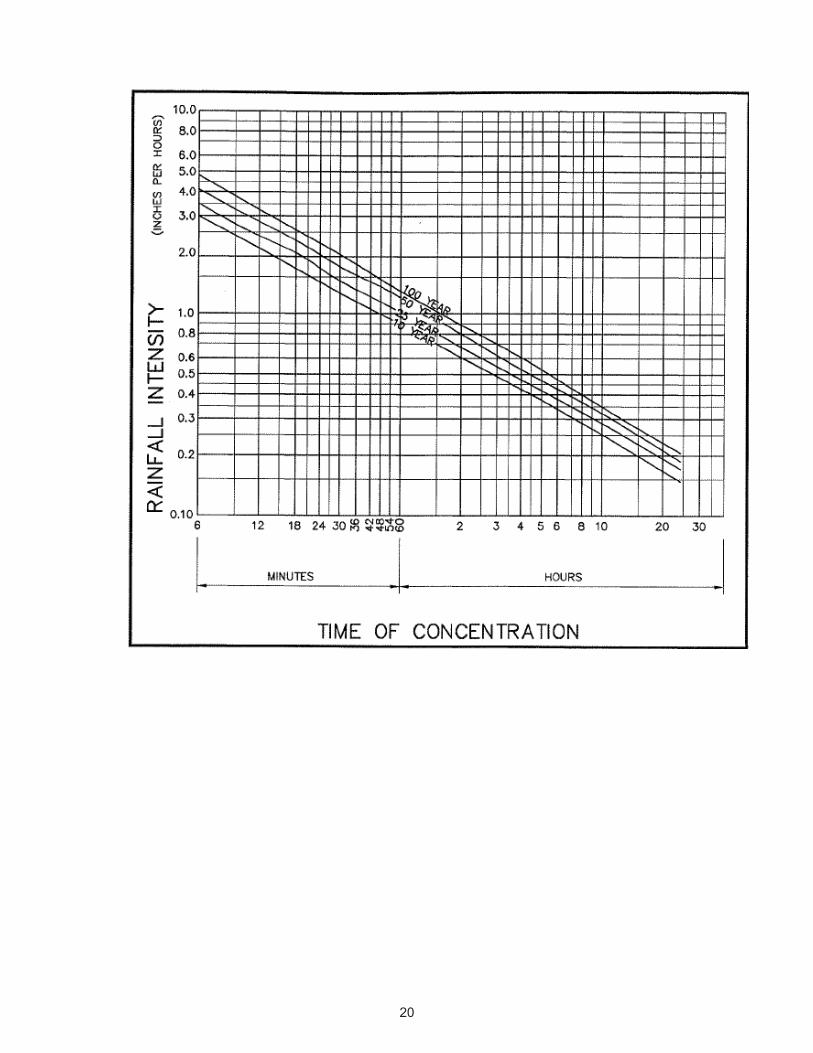
The Rational Method shall be used to compute the total volume of runoff from a development with an area less than 200 acres. For drainage areas in excess of 200 acres, or where the design engineer determines that the Rational Method is not practical or appropriate, the design engineer shall provide all documents necessary to confirm computations.
All calculations shall be prepared by a registered professional engineer with a current license to practice in the State of California. The rainfall intensity curveincluded herein is available for use as part of the hydrology calculations. In computing runoff in a partial development, adequate provisions must be made for the drainage of the overall improvements and/or drainage tributary. Hydrology calculations shall be based upon ultimate land use designations in accordance with the adopted General Plan.
B. Hydraulic Calculations
Closed Conduits
Design considerations for closed conduits are as follows:
Pipe friction losses determined by Manning's equation.Entrance and exit losses. Tail-water impacts. Entrance control headwater.
For each length of pipe, the hydraulic grade line (hgl) at the pipe entrance and exit shall be determined assuming both inlet control and outlet control. The more restrictive shall control. The storm drain system shall be designed to meet the following conditions.
1. The hydraulic grade line shall be a minimum of 0.50 feet below the elevation of inlet grates and manhole covers of all structures for a design storm of 25 years. Said gradient shall be shown on the profile for storm drain systems. 2. Minimum pipe diameter allowable on any public storm drain shall be 18 inches. 3. Storm drain systems shall be designed for the 25-year storm. In a sump condition a secondary overland flow shall be included such that during the 100-year storm, all buildings or first floor elevations shall be at least one foot (1') above the 100-year storm. 4. Street capacity shall be defined as the 10-year storm confined between
the crown of the street and the top of curb. Where the street capacity is exceeded at either the curb or the crown, a storm drain or other approvedfacility shall be provided to convey the excess flows. In all cases, the 100-year storm shall be contained within the right-of-way.
Cross culvert design shall be determined on the basis of a twenty-five year storm with no head. The hydraulic entrance condition shall be such that the 25-year discharge will have the specified freeboard in the upstream channel or waterway and that the 100-year discharge will be contained within the banks of the upstream waterway or drainage easement. The entrance to the closed conduit minor waterway may be submerged provided that the above criteria are satisfied. The invert elevation of the closed conduit entrance shall not be set lower than the natural flowline of the waterway or open channel flowing into it.
Open Channels
Open channels shall be designed based on Manning's equation. The impacts of culverts, bridges or other structures affecting the hydraulic performance of the
channel shall be considered as appropriate.
The City Engineer may require more complete analysis if he/she determines conditions merit a more thorough study. This additional analysis may include determination of the water surface profile, analysis of critical sections, and analysis of erosion and/or sedimentation.
Maximum velocity for channels flowing full shall be limited to preclude erosion.Freeboard of at least one foot based on 25-year volumes shall be provided for allchannels. Lining treatments shall extend to the full height of freeboard. The 100-year discharge shall be contained within the banks or within the easement established for the channel. For natural waterways, the design flow may be allowed in the natural overflow area.
C. Post-Construction Storm Water Quality and Watershed Protection
For the purposes of maintaining the quality of storm water runoff, preventing injury to downstream watercourses, and maintaining groundwater recharge, Low Impact Development Guidelines shall be utilized. These guidelines are referenced as a placeholder and transition into more specific criteria that will be developed by the Water Board and implemented by all Central Coast partner agencies on January 1, 2013.
All development projects are subject to interim LID design guidance on file with the City Engineer.
D. Retention Basins
Storm water retention for flood control purposes shall be applied as determined by the design engineer; typically where downstream conditions are constrained and properties are threatened or have been flooded in conditions existing prior to upstream development. Criteria for the design of retention basins may be reviewed on a case by case basis. Typically, the volume of storage for flood control purposes is based upon the post-development 100-year, 24-hour storm event.
E. Detention Basins
A detention basin is defined as a holding facility where the rate of flow from the basin is limited to that rate historically occurring prior to development. The volume of storage of a detention basin shall be determined by theoretically matching the historical hydrograph of flows leaving the previously undeveloped land under consideration.

F. Storm Drain Alignment Criteria
Storm drain lines shall be parallel with street centerlines to the extent practical and typically twelve feet southerly or easterly of the centerline (Standard Detail U-1).
Maximum spacing for manholes shall be 500 feet. Manholes shall be located at junction points, changes in gradient and changes in conduit size. The alignment between any two manholes may consist of one curve and one tangent section. A manhole must be placed at the beginning or end of any curve. Reverse curves are not acceptable between manholes. Curve radii shall conform to pipe manufactures recommendations. All manholes must be located in areas accessible for maintenance.
G. Easements
Drainage facilities must be located in a public street right-of-way or within a public drainage easement. Easements for closed conduits shall be a minimum width of twenty feet (20). Easements for open channels shall have sufficient width to contain the channel with a minimum ten foot (10) setback to side slopes and afifteen (15) foot wide service road on at least one side.
V-3. MATERIALS
Closed Conduits shall be high density polyethylene (HDPE) with water tight couplings,reinforced concrete pipe (RCP), or hot-dipped galvanized Corrugated Metal Pipe (CMP).
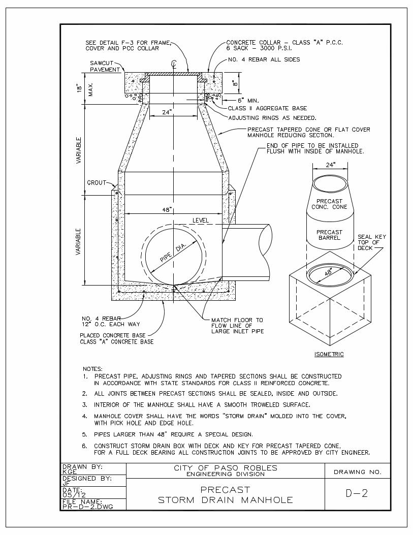
Standard pre-cast concrete manholes shall be typical (Standard Detail D-2). Special designs of manholes or junction boxes shall be approved by the City Engineer. Open conduits may be natural watercourses, earthen channels, or channels lined withmaterials such as:
Native grass which forms a thick, dense sod without irrigation;Turf reinforcement mats, erosion control blankets, or geotextile materials.Such material may be interplanted with vegetation;Rock slope protection in accordance with Caltrans specifications; Bioengineering methods recommended in Natural Resource Conservation Service’s Streambank Soil Bioengineering Field Guide for Low Precipitation Areas;
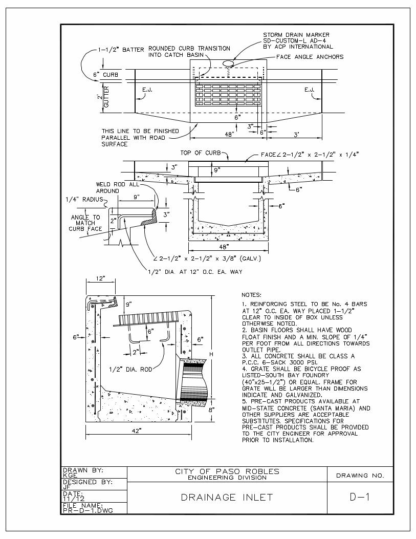
Drain inlets shall conform to Standard Detail D-1. Grates shall be adequate for AASHTO's HS-20 traffic loading and shall be double dipped hot galvanized or approved equal.
All headwalls, wing-walls, and end-walls shall be constructed of Class “A” reinforced Portland cement concrete. Trash racks shall be provided where necessary to prevent clogging of culverts and storm drains.
V-4. CONSTRUCTION GUIDELINES
A. General
Excavation, pipeline placement and backfill shall conform to Section VI-3 of these specifications for sanitary sewers.
Concrete structures shall be placed in accordance with these Standards and Specifications and shall conform to the requirements of Section 51 of Caltrans Standard Specifications.

SECTION VI
SANITARY SEWERS
VI-1. DESIGN GUIDELINES
Sewer collection lines and appurtenant structures within the jurisdiction of City of Paso Robles shall be constructed in accordance with plans prepared by a Professional Civil Engineer, consistent with these specifications and as approved by the City Engineer.
A. Design Flow
Typically, the minimum size sewer pipe shall be not less than 8 inches inside diameter. Six inch diameter pipe may be used on terminal branch lines, less than 200 feet in length. An average flow of 100 gallons per person per day for residential developments shall be used for design purposes, with the peak flow double the average flow. Pipes shall be sized to handle peak flows with pipe flowing half full.
Sizing of pipes shall include consideration of the ultimate upstream development in accordance with density established in the Land Use Element of the General Plan, the City Sewer Master Plan or as determined by the City Engineer.
B. Gradient
The following table indicates the minimum slopes acceptable for the design of sewer lines in the City of Paso Robles. Lesser slopes may be approved by the City Engineer where topographic features preclude the use of the table below (It is not acceptable practice to increase pipe sizes for the purpose of reducing the slopecriteria to meet minimum standards without regard to the volume of flow. See minimum flow rates below).
Diameter Slope in Feet/Foot (Minimum Acceptable)6” .01008" .0050
10" .002512" .0020
Special provisions for erosion protection shall be provided where design velocities for sanitary sewer pipelines exceed ten feet per second. Where sufficient flow exists, design velocities should exceed two feet per second. The maximum design discharge rate shall not exceed the critical flow rate. Sanitary sewer pipe should notbe designed for flow conditions at critical slope and velocity.
C. Location
All sanitary sewer mains shall be located in public streets. In new streets the sewer main shall be typically located six feet south or east of the centerline of the right-of-way. Where a public road is not available a sewer main may be located in an easement specifically dedicated to the City for the purposes of construction, operation and maintenance of a sanitary sewer main. The minimum width of the easement shall be 20 feet. A minimum 12-foot wide all weather aggregate base access road must be provided in the easement.
No sanitary sewer shall be located within fifty feet of a City water well.
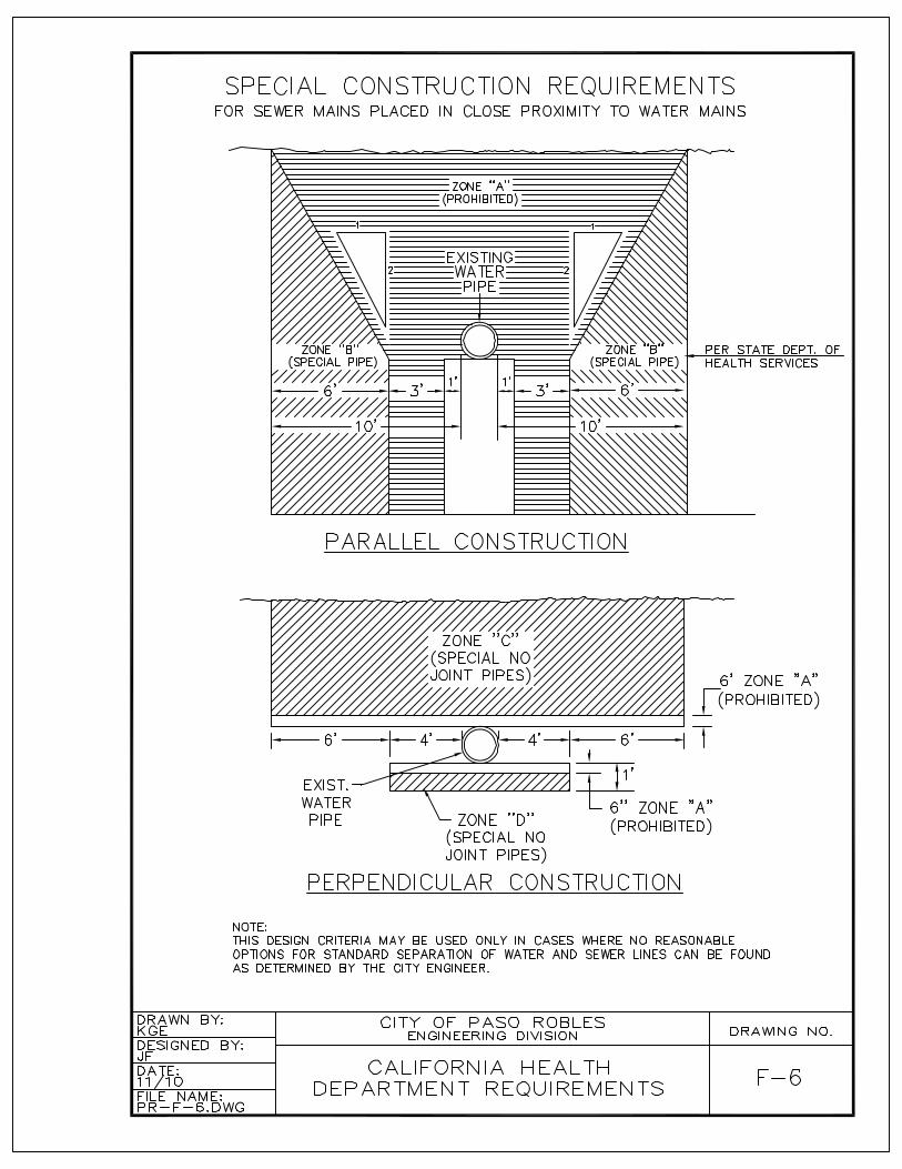
Where sewer mains are constructed in close proximity to water mains the design of these lines shall conform to special construction requirements as outlined by the State Department of Health Services in their “Criteria for the Separation of Water Mains and Sanitary Sewers”. This design criteria is outlined on City Standard Detail F-6.
D. Alignment
Sewer pipelines shall typically be designed in straight alignments between manholes. Curved sewer lines will be allowed where the minimum radius conforms to the pipe manufacturers recommendations. In no case shall the radius be less than 240 feet.
The alignment between any two manholes may consist of one curve and one tangent section. A manhole must be placed at the beginning or end of any curve.Reverse curves are not allowed between manholes.
E. Depth
The minimum design depth of a sanitary sewer system shall be six feet. It is desirable to obtain a cover of 48 inches for the service lateral at the property line. Under topographic constraints, lesser depths may be approved by the City Engineer.
F. Manholes
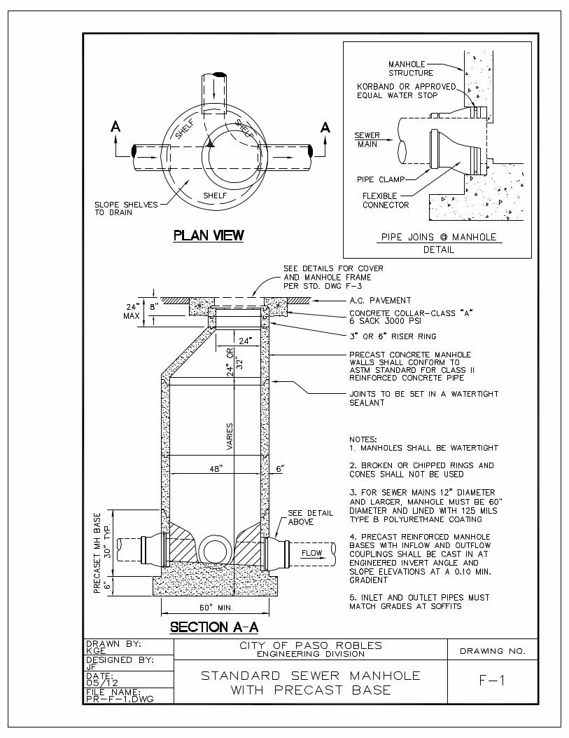
Maximum spacing for manholes shall be 500 feet. Manholes shall be designed and constructed in accordance with Standard Detail F-1.
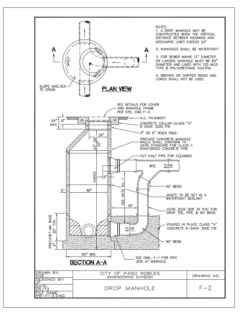
Drop manholes may be constructed in accordance with Standard Detail F-2 where the vertical distance between incoming and discharge sides of the manhole exceeds 24 inches.
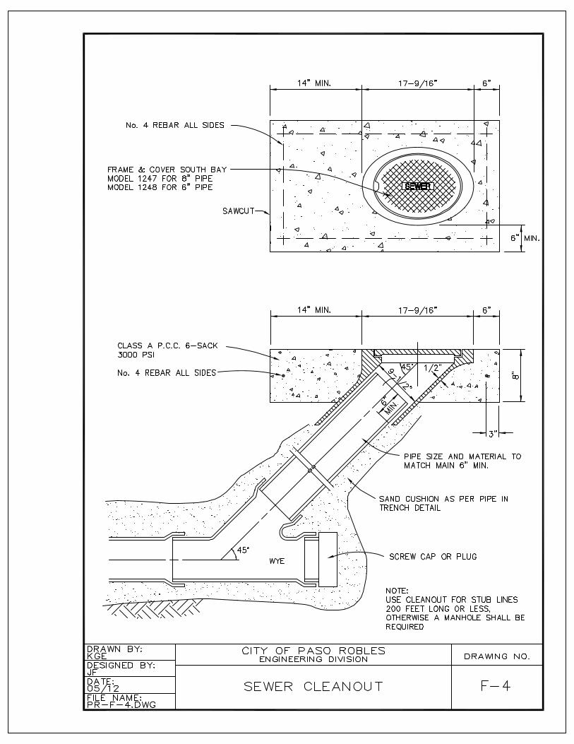
G. Sewer Clean-out
A clean-out may be used in lieu of a manhole on any branch line with a length of 200 feet or less. Any branch line more than 200 feet in length shall have a manhole at the end.
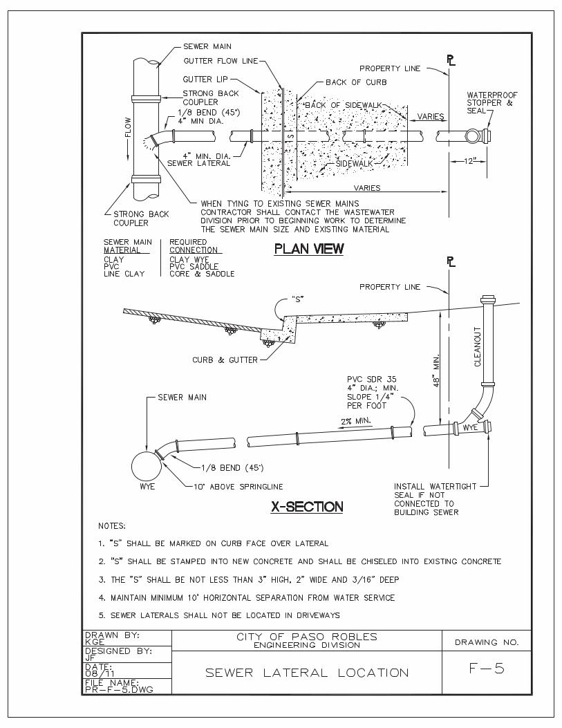
H. Private Laterals
Each private property shall have its own separate and distinct sanitary sewer lateral connection to the City main. All sewer laterals must be connected downstream of a sewer manhole or sewer clean-out. In no case shall a sewer lateral be connected directly to a sewer manhole.
In all new subdivision work, the house service laterals from the sewer to the property line shall be installed at the time the sewer is constructed. Each house service line shall be referenced to the plan stationing. The lateral shall be placed a minimum of five feet from any property line and from any water service.
The minimum size of a lateral shall be four inches (4”) inside diameter. Laterals larger than four inches shall be sized in accordance with Uniform Plumbing Coderequirements. Commercial laterals shall be a minimum of six inches (6") inside diameter. Laterals greater than six inches shall connected to the main with amanhole.
VI-2. MATERIALS
A. Pipe
All sanitary sewer PVC pipe must meet ASTM Standard 3034/SDR 35. Pipe used in construction of force mains shall be PVC Class 150 C900. Tracer wire shall be included with force main pipe.
B. Manholes
Manholes shall be watertight structures constructed by placing precast concrete sections on a pre-cast concrete base.
Where sewer mains are 12-inch diameter or larger, the inside wall of the manhole must be lined with a minimum 125 mils of Type B Polyurethane coating (Sancon 100 or approved equal).
VI-3. CONSTRUCTION GUIDELINES
A. Excavation for Sewers
Unless otherwise specified, the excavation for sewer pipe shall be an open trench, excavated to six inches below the bottom of the pipe. This undercutting shall be refilled with suitable bedding material.
Whenever the bottom of the trench is soft, yielding, or unsuitable as a foundation for the pipe, sufficient crushed rock or coarse, clean gravel shall be rammed into the soft material until, in the opinion of the observing Geotechnical Engineer a suitable condition is achieved. If such treatment does not provide a proper foundation, the unsuitable material shall be removed to a depth determined by the Geotechnical Engineer.
When water is encountered, the trench shall be kept dewatered until the laying and jointing of the pipe, and placing of the bedding material has been completed andobserved by the City inspector. The Contractor shall place not less than six inchesof 2-1/2” maximum size rock below the required bedding material, or otherwise de-water the trench in a manner which has received prior approval of the Engineer. Temporary covers of 3/8" steel plate of sufficient size to adequately cover the opening shall be placed on manhole cones until the pavement is completed. Ribs shall be welded to the underside of the cover to hold it in place during the grading and paving operations.
The total depth of the manhole throat measured from the top of the frame shall not exceed 18 inches. Manhole frames and lids shall be placed a minimum of 12" above natural ground or high water when placed in easements outside of un-paved areas.
B. Safety
All work shall be performed in accordance with the requirements of the State of California Division of Industrial Safety.
The Contractor shall conform to the permit requirements of the Division of Industrial Safety and shall obtain a trenching permit directly from said State Office prior to such activity.
The Contractor's attention is directed to the provisions of the State Labor Codeconcerning trench excavation safety plans. (Note: Contractors are hereby advised that the independent monitoring regulations of OSHA, as enforced by CAL OSHA officers, is to be complied with at all times).
C. Bracing and Shoring
As required by the "Trench Construction Safety Orders" of the California State Industrial Accident Commission, sufficient bracing, shoring and access equipment shall be installed in trenches to insure the safety of workmen, and to protect and facilitate the work. Where practical, all such bracing and shoring shall be removed from the trench as the backfilling proceeds.
D. Laying of Sewer Pipe
Pipe shall be laid in conformity to the lines and grades established on the approved plans. Pipe shall be laid continuously upgrade with the bell of the pipe forward. Each length of pipe shall be laid on a firm bed and shall have a true bearing for the entire length. No wedging or blocking up of the pipe will be permitted.
Both bell and spigot shall be clean and lubricated before the joint is made. Care shall be taken that nothing but the joint-making material enters the joints. At the end of each work day the end of the pipe must be sealed to preclude infiltration of water, dirt or debris.
E. Trench Backfill
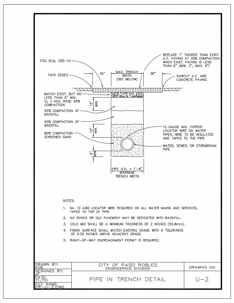
Bedding material meeting the minimum standards listed below, shall be deposited and compacted to 90% relative compaction in the trench uniformly on both sides of the pipe for the full width of the trench and to a depth of 12 inches over the top of the pipe (Standard Detail U-2).
Sand Equivalent 20
Sieve Size Percentage Passing Sieve1" 100No. 4 80-100No. 200 0-15
The balance of the backfill shall contain no rock or boulders in excess of 2 inches and shall be free from all deleterious matter. Backfill shall be compacted to a relative compaction of 90%. The top 12 inches shall be brought to 95% compaction. The backfill under and around any and all pipes shall be thoroughly consolidated before any additional material is placed. Compaction methods must be carried out so no damage or displacement of the pipe occurs.
F. Connection to Existing Manholes
Connection to existing manholes shall be made by carefully core-drilling an openingin the wall of the manhole. The pipe shall be inserted with elastomeric ring-sealthrough the opening flush with the inside wall. The opening around the pipe shall be
packed with a stiff mix of cement mortar, thoroughly compacted to form a watertight connection. The mortar shall be finished smooth and flush with the interior surface of the manhole. Channelizing of the flow through the manhole shall conform to the details shown on the standard Drawings for new manholes.
The Contractor shall notify the City Engineer 72 hours in advance before any connection is made to existing structures. Work shall be scheduled so that interruption of flow is held to a minimum.
VI-4. TESTING
Prior to acceptance all sewer lines shall be cleaned, tested for leakage by a standard low pressure air or water test, tested for deflection with a mandrel, and inspected by video. All testing shall be performed prior to street paving and after all backfill and compaction procedures are complete, streets have been graded and the sub-grade of structural street sections has been compacted and prepared appropriately.
Leakage test is by internal air pressure or water. Infiltration test is by measurement of rate of flow of water. Each section of pipe between manholes, along with the manholes, shall be tested. Use the air test where the difference in elevation between the invert of the upper structure and the invert of the lower structure is more than 10 feet.
Testing procedures shall be as outlined here:
A. Air Test Procedure
Each section of sanitary sewer between two successive manholes shall be tested by plugging all pipe outlets with inflatable and expandable test plugs. Pressure-relief valves shall be set to limit the internal pipe test pressure to five pounds per square inch gauge pressure (5 psig). Air shall be slowly added until the internal pressure is raised to 4.0 psig. Care shall be taken to guard against the sudden expulsion of a poorly installed plug or a plug that is partially deflated.
The internal pressure of 4 psig shall be maintained for at least two minutes to allow the air temperature to stabilize after which the air supply shall be disconnected and the pressure allowed to decrease to 3.5 psig. The Table below provides theminimum time requirements for a pressure drop to occur from 3.5 psig to 3.0 psig.
Should the test disclose an air loss rate greater than permitted, the contractor shall, at his own expense, locate and repair the defective joints or pipe sections. After the repairs are completed, the line shall be retested until the air loss rate is less than specified below.
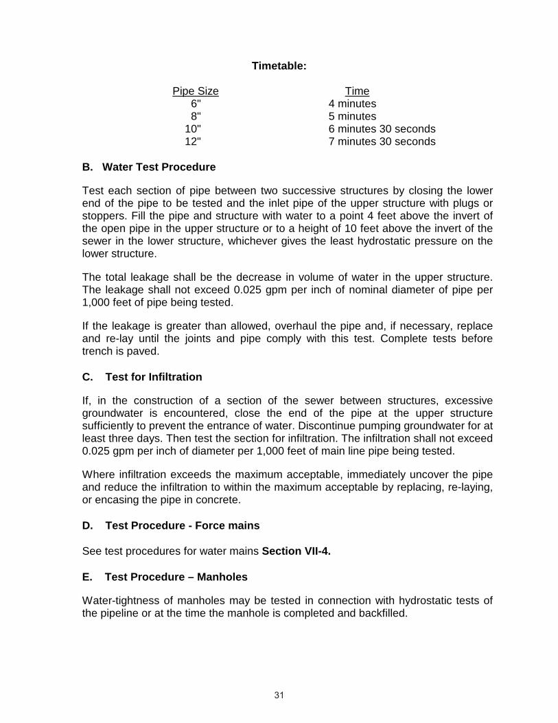
Timetable:
Pipe Size Time6" 4 minutes8" 5 minutes
10" 6 minutes 30 seconds12" 7 minutes 30 seconds
B. Water Test Procedure
Test each section of pipe between two successive structures by closing the lower end of the pipe to be tested and the inlet pipe of the upper structure with plugs or stoppers. Fill the pipe and structure with water to a point 4 feet above the invert of the open pipe in the upper structure or to a height of 10 feet above the invert of the sewer in the lower structure, whichever gives the least hydrostatic pressure on the lower structure.
The total leakage shall be the decrease in volume of water in the upper structure. The leakage shall not exceed 0.025 gpm per inch of nominal diameter of pipe per 1,000 feet of pipe being tested.
If the leakage is greater than allowed, overhaul the pipe and, if necessary, replace and re-lay until the joints and pipe comply with this test. Complete tests before trench is paved.
C. Test for Infiltration
If, in the construction of a section of the sewer between structures, excessive groundwater is encountered, close the end of the pipe at the upper structure sufficiently to prevent the entrance of water. Discontinue pumping groundwater for atleast three days. Then test the section for infiltration. The infiltration shall not exceed 0.025 gpm per inch of diameter per 1,000 feet of main line pipe being tested.
Where infiltration exceeds the maximum acceptable, immediately uncover the pipe and reduce the infiltration to within the maximum acceptable by replacing, re-laying, or encasing the pipe in concrete.
D. Test Procedure - Force mains
See test procedures for water mains Section VII-4.
E. Test Procedure – Manholes
Water-tightness of manholes may be tested in connection with hydrostatic tests of the pipeline or at the time the manhole is completed and backfilled.
Fill the manhole with water to an elevation 1 foot below the bottom of the cone section with a maximum water depth of 20 feet. Plug inlets and outlets with stoppers or plugs and fill the manhole to the limits indicated above. The maximum allowable drop in the water surface shall be 1/2 inch for each 15-minute period of testing.
Even though the infiltration is less than the maximum acceptable, stop any individual leaks that may be observed.
F. Cleaning
The contractor shall clean all lines with a Wayne-type sewer cleaning ball underhydrostatic pressure and shall apply a mandrel to test for deformation. The mandrel shall be the 9-vane design and sized to 95% of the nominal internal diameter of the pipe.
G. Video
All new sewer main installations shall be observed by video and reviewed for acceptance by the Wastewater Division Manager. The video shall be DVD format and color quality. The video shall have a digital display with a date and pipeline footage as a minimum tape reference. The film must also be clear and legible withadequate lighting.
All videos shall include a written log. The log shall have a legible map and a North arrow. Manholes shall be marked respectively and directional arrows indicating flow shall be shown.
A gauge in front of the camera shall be used to measure the depth of debris or standing water. The maximum tolerance for the depth of standing water is 0.5 inches.
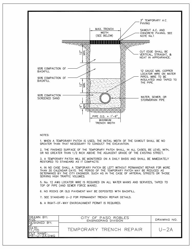
H. Placement and/or Replacement of Road Surfaces
Trench paving shall conform to Standard Detail U-2. New street paving shall conform to Section IV of these specifications.
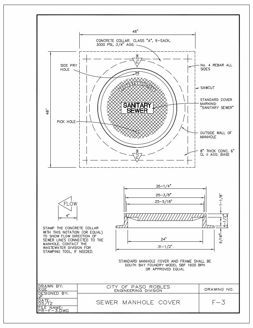
All testing procedures outlined above must be completed prior to pavement replacement or new street paving. After street paving, all manholes shall be raised to grade and concrete collars shall be installed in accordance with Standard Detail F-3. The concrete collar shall be stamped to show flow direction of sewer lines connected to the manhole. Prior to acceptance of new sewer lines, the lines shall be thoroughly cleaned once again.
SECTION VII
WATER
VII-1. DESIGN GUIDELINES
Water pipelines and appurtenant structures within the jurisdiction of the City of Paso Robles shall be constructed in accordance with plans prepared by a Professional Civil Engineer, consistent with these specifications and as approved by the City Engineer.
A. Design Flow
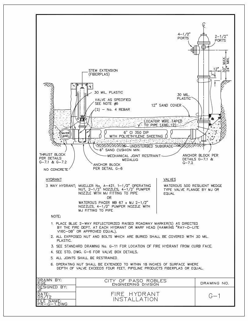
Water pipelines shall be designed such that water supply can be adequately delivered under maximum day demand plus fire-flow conditions. Minimum fire flow shall be provided as required in the 2007 California Fire Code (CFC) Appendix BB, Table BB105.1. Minimum number of fire hydrants and their location shall be as required by 2007 CFC Appendix C.
B. Distribution System
The distribution system, wherever possible, shall be in loop/grid form to increase fire-flow capability, improve water quality, reduce maintenance costs, and better conserve water resources by reducing system-flushing requirements. If a dead end is unavoidable, mains shall meet the criteria specified in Paragraph D below andshall not exceed 1,000 lineal feet. If an opportunity exists to create a looped system by extending main, the loop must be made. Dead-end mains must terminate with astandard fire hydrant. The design and installation of the water system must becompatible to serve the ultimate service area in accordance with the General Plan.
Water distribution systems shall be designed to maintain normal operating pressures of not less than 40 psig at the service connection during peak system demand. If 40 psig cannot be obtained, a City-approved booster pump/station with backflow prevention is required.
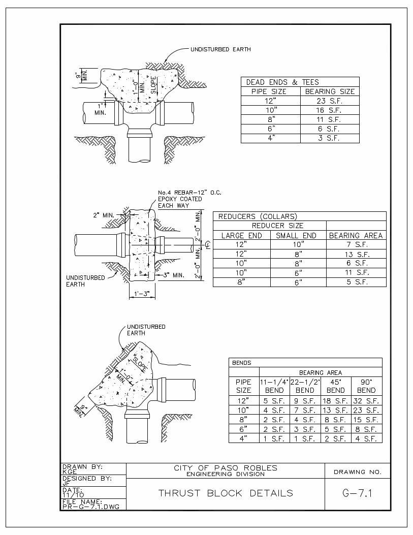
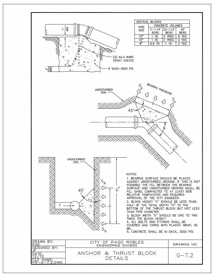
Concrete anchor and thrust blocks shall be provided at all discontinuities in accordance with Standard Details G-7.1 and G-7.2.
C. Regulations Relating to Cross Connections
Reference is also made to Title 17, Chapter V, Sections 7583-7622 inclusive of the California Administrative Code, regulating the construction of cross connections between drinking water systems and other sources of water. All industrial,commercial, multi-story buildings and landscape connections shall be equipped with an RP type backflow device located within 10-feet of the water meter. Under no circumstances are any connections allowed between the backflow device and the service meter. All construction shall be in strict compliance with said regulations.
Residential fire sprinkler systems must be “passive purge”. Passive-purge fire sprinkler systems serve a single commonly used toilet in addition to the fire sprinklers. The toilet shall be on a remote portion of the sprinkler system or the system shall be designed as a loop so that the water moves through a majority of the fire sprinkler system piping when the toilet is flushed. All other residential sprinkler systems must have an RP-type backflow device located within 10 feet of the water meter and requires prior approval of the Fire Chief and Water Manager.
D. Minimum size
In general, the minimum size pipe shall be not less than 8 inches inside diameterwith the following exceptions:
1. Dead-end mains require special approval of the City Engineer, Fire, and Public Works departments. The minimum size for dead-end mains is to be determined based on pipeline length, fire-flow requirements, normal system pressures, anticipated demands, and the number of dwelling units servedand must also satisfy the following:
4-inch mains must be less than 150-feet long and serve fewer than 10dwelling units.
6-inch mains must be less than 350 feet and serve less than 25 dwelling units.
E. Location and Depths
All water mains shall be located in public streets, typically six feet north or west of the centerline of the right-of-way. Where a public road is not available a water main may be located in an easement specifically dedicated to the City for the purposes of construction, operation and maintenance of a water main. The minimum width of the easement shall be 20 feet, or 30 feet if located between two structures. A 12-foot wide all-weather aggregate base access road capable of supporting 60,000 lbs of equipment must be provided in the easement. No fences or other obstacles are to be placed around or within the easement that might limit access.
Water mains shall be installed at a depth which will provide a minimum cover of 36inches over the top of the pipe measured from the finished grade. Mains 12 inchesand larger, or any water main not located in a public street, shall have minimum cover of 48 inches. All new mains are to have a minimum clearance of 18 inches between all adjacent utilities.
Where water mains are constructed in close proximity to sewer mains the design of these lines shall conform to special construction requirements as outlined by the State Department of Health Services in their "Criteria for the Separation of Water
Mains and Sanitary Sewers". This design criterion is outlined on City Standard Detail G-13.
F. Water Services
Water services and meters shall be placed a minimum of five feet from any property line and 10-feet from any sewer lateral. Service lines shall normally be installed at the time the main is constructed to avoid frequent cutting of the street. Services are to be sized according to the meter being installed at the time water service begins.
G. Valves
Gate valves shall be attached by flange on all legs of tees and crosses. In-linevalves should be installed at increments of 600 feet on continuous lines without main intersections and connect to the main with mechanical joint (MJ) fittings. Valves should also be spaced so that not more than two fire hydrants should be out of service at any one time. Valves 12-inches and larger shall be butterfly type.
H. Fire Hydrants
Fire hydrants shall be placed at street intersections whenever possible, and should be located to minimize the hazard of damage by traffic. The average spacing between hydrants should not exceed that required by the 2007 CFC Appendix C or otherwise specified by the City’s Fire Chief. All joints and fittings between the main and the hydrant shall have thrust restraint. The minimum size main serving the fire hydrant shall be 6-inch with a gate valve installed at the main and all as shown onCity Standard Detail No. G-1.
I. Air and Vacuum Release Valves
Air and vacuum release valves shall be installed in accordance with City Standard Detail No. G-8 at all high points along a main where it is likely that air pockets may form. All valves shall be designed for a minimum of 150 PSI operating pressure. A gate valve (for connections greater then 2-inch in diameter) or corporation stop (for connections equal to or less then 2 inches) shall be installed at the connection to the main to provide a positive closure between the main pipeline and the air and vacuum release valve. The air and vacuum release vent outlet shall be installed above ground in such manner as to preclude back-flow.
J. Blow-offs
Blow-offs (BOs) shall be installed in accordance with City Standard Detail No. G-9at all low points along the main to provide for adequate flushing, draining and maintenance. Four-inch BOs are to be installed on pipeline sizes 14-inches and smaller and 6-inch BOs are to be installed on pipelines 16-inches and larger.
VII-2. MATERIALS
A. Pipe
Pipe used in the construction of water distribution systems shall be either ductile ironor PVC and shall meet the standards of the American Water Works Association (A.W.W.A.) where applicable. The City Engineer may specify which types shall be used in any instance.
1. PVC pipe shall be a minimum of D. R. 18 and shall conform to and meet the requirements of AWWA Specification C900 for sizes 4-inches through 10-inches.
2. Ductile iron must be pressure class 350 for 12-inches diameter and shallconform to AWWA C151.
3. Locator wire (insulated AWG 12) must be installed and taped to the top of all new pipes. All locator wire connections are to be made with water/weather tight connectors.
B. Fittings
Bends, elbows, tees, crosses, and special fittings shall be cast iron or ductile iron, and shall conform to and meet requirements of AWWA Specification C110. At connections to adjacent pipe, the fittings shall have rubber gasket joints conforming to AWWA Specification C111 with the exception of push-on joints. Push-on fittings and push-on joints adjacent to valves and fittings are not permitted.
C. Bolts and Nuts for Flanges
Bolts and nuts for all flanges shall be Type 304 or 316 stainless steel conforming to ASTM A 193, Grade B8M, for bolts and ASTM A 194, Grade 8M, for nuts.
Provide washers for each nut. Washers shall be of the same material as the nuts. Provide Lubricant for Stainless Steel Bolts and Nuts. Lubricant shall be chloride free and shall be RAMCO TG-50, Anti-Seize by RAMCO, Specialty Lubricants Corporation Husky Lube O'Seal, or equal.
D. Valves and Valve Boxes
Valve boxes shall be installed in accordance with City Standard Detail No. G-6.Valves shall have a 2-inch square operating nut, be resilient wedge, epoxy lined, open in counter-clockwise direction and meet the requirements of AWWA Specifications C509 for gate valves. The cover shall be marked "WATER". When the depth from finish grade to the operating nut of the valve is 4 feet or greater the valve operating nut shall be extended to within 6 inches of finished surface using a Fiberplas valve stem extension or approved equal.
Butterfly valves are required on mains larger then 12-inches in diameter and require approval by the City Engineer, and Water Resources Manager.
E. Water Service Connections
Service lines shall have a 1-inch copper-tube-size (CTS) polyethylene (PE) for domestic single family residential services serving 3/4 or 1-inch meters, and 2-inch PE CTS service lines shall be installed for 1.5 and 2 inch meters. Commercial, industrial, or irrigation service line sizes are to be as shown on the plans and approved by the City Engineer. Water service connections shall be installed in accordance with City Standard Drawing Nos. G – 2 and G –3.
VII-3. CONSTRUCTION GUIDELINES
A. Connection to Existing Mains
The City Water Division shall be provided not less than 72 hours notice before connection is made to any existing main. Notification shall include arrangement of a meeting at the site to discuss materials and operations associated with the connection.
The Water Division shall coordinate and perform all shutdowns of City water facilities. Shut downs may occur only when inconvenience to existing customers is minimized. Connections shall be made only after complete and satisfactory preparation for such work has been made, in order that the shutdown may be as short as possible. The City Water Division will be responsible for all main valve operation.
Connections of fire lines and new water mains to existing water mains shall be accomplished by the installation of new tees and valves. Hot taps will occur only in circumstances specially approved by the Water Division Manager.
In-line valves shall be placed prior to construction of the new connection where existing in-line valves do not meet the design guidelines in Section VII-I; where the installation of in-line values will significantly reduce the number of customers affected by interruption of service or where existing critical connections would otherwise be affected including schools or buildings with a high number of tenants.
B. Excavation for Water Lines
The minimum trench width shall be the nominal diameter of the pipe plus eighteen (18) inches, and be ample to permit the proper installation of the pipe and appurtenances. (see City Standard Detail No. U – 2)
Excavated material shall be piled in such a manner that it will not endanger the work and will offer minimum obstruction to traffic. Open trenches and waste piles shall be adequately barricaded and lighted.
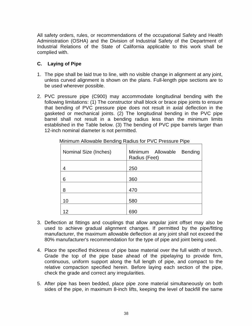
All safety orders, rules, or recommendations of the occupational Safety and Health Administration (OSHA) and the Division of Industrial Safety of the Department of Industrial Relations of the State of California applicable to this work shall becomplied with.
C. Laying of Pipe
1. The pipe shall be laid true to line, with no visible change in alignment at any joint, unless curved alignment is shown on the plans. Full-length pipe sections are to be used wherever possible.
2. PVC pressure pipe (C900) may accommodate longitudinal bending with the following limitations: (1) The constructor shall block or brace pipe joints to ensure that bending of PVC pressure pipe does not result in axial deflection in the gasketed or mechanical joints. (2) The longitudinal bending in the PVC pipe barrel shall not result in a bending radius less than the minimum limits established in the Table below. (3) The bending of PVC pipe barrels larger than 12-inch nominal diameter is not permitted.
Minimum Allowable Bending Radius for PVC Pressure Pipe
Nominal Size (Inches) Minimum Allowable Bending Radius (Feet)
4 250
6 360
8 470
10 580
12 690
3. Deflection at fittings and couplings that allow angular joint offset may also be used to achieve gradual alignment changes. If permitted by the pipe/fitting manufacturer, the maximum allowable deflection at any joint shall not exceed the 80% manufacturer's recommendation for the type of pipe and joint being used.
4. Place the specified thickness of pipe base material over the full width of trench. Grade the top of the pipe base ahead of the pipelaying to provide firm, continuous, uniform support along the full length of pipe, and compact to the relative compaction specified herein. Before laying each section of the pipe, check the grade and correct any irregularities.
5. After pipe has been bedded, place pipe zone material simultaneously on both sides of the pipe, in maximum 8-inch lifts, keeping the level of backfill the same

on each side. Carefully place the material around the pipe so that the pipe barrel is completely supported and no voids or uncompacted areas are left beneath the pipe. Use particular care in placing material on the underside of the pipe to prevent lateral movement during subsequent backfilling.
6. Thrust and Anchor Blocks shall be placed in accordance with City Standard Details No. G7.1 and G7.2 at bends of 111/4, 221/2, 45 or 90 degrees; at the end of plugged mains; behind each tee and cross and at the back of fire hydrants. The thrust block shall extend from the fitting to undisturbed soil, shall be kept clear of the joints, and shall be of such bearing area as to assure adequate resistance to the water pressure force to be encountered.
7. Compact each lift to the relative compaction specified per City Standard Details No. U2
8. Each section of pipe and each fitting shall be thoroughly cleaned before it is installed. All pipe, fittings, valves, etc., shall be carefully lowered into the trench by suitable tools or equipment, in such manner as to prevent damage to the pipe, lining, coating, fitting or other appurtenances. Under no circumstances shall pipe or accessories be dropped into the trench.
9. Push the backfill material carefully onto the backfill previously placed in the pipe zone. Do not permit free-fall of the material until at least 2 feet of cover is provided over the top of the pipe.
10.Do not operate heavy equipment or a sheepsfoot wheel mounted on a backhoe over the pipe until at least 2 feet of compacted fill has been placed over the pipe.
11.Keep the trench dry until the pipelaying and jointing are complete
12.Whenever pipe placement is discontinued for short periods, or when work is stopped at the end of the day, the open ends of all mains shall be closed withwater-tight plugs or bulkheads. The plug or bulkhead shall not be removed unless or until the trench is dry.
13.Valves shall be set plumb, supported on a concrete base and properly fitted to the adjacent sections of the main. A valve box shall be installed over each valve. City Standard Details No. G6
D. Trench Backfill
All the requirements for backfilling of sewer line trenches set forth in Section VI-3Eshall apply to backfill of water main trenches.
VII-4. TESTING
A. Testing
Each section of the pipe shall be tested in accordance with following procedures.The pipe shall be slowly filled with water, and all air shall be expelled from the pipe. The release of the air can be accomplished by opening hydrants and service line cocks at the high points of the system and the blow-offs at all dead-end. After the system has been filled with water and all air expelled, all the valves controlling the section to be tested shall be closed, and the line be allowed to set for a period of not less than 24 hours. All line filling and valve operation shall be done by the City Water Division.
Final cleaning and testing of water lines shall take place after all construction work is completed, with the exception of final paving. Cleaning and testing shall be performed in the presence of the Public Works Inspector.
The pipe shall then be refilled, if necessary, and subjected to a pressure of not less than 200 PSI or 50 PSI over the pipe class being installed, whichever is greater, for a period of not less than two hours.
Any leaks, cracks or defective pipe, fittings, valves, hydrants or other appurtenancesdiscovered during the test shall be removed and replaced with sound material, and the test repeated until the system is proved satisfactory.
The allowable make-up water used to maintain test pressure within 5 psi in the test section shall not exceed 50 gallons per mile per 24 hours per diameter of pipe tested.
Example: L = 3240 ft of 8-inch pipe for 2 hour test
50 gallons x 3,240 ft x 2 hours x 0.67 ft (diameter) = 1.713 gallons allowable make-up water 5,280 ft/mile 24 hours
B. Flushing and Disinfecting
After the pressure test, the system shall be thoroughly flushed out and disinfected in accordance with AWWA Standards and/or the requirements of the County Health Department.
C. Replacement of Road Surfaces
Paving shall not proceed until all testing, flushing and disinfecting have been performed to the satisfaction of the City Engineer.