Embed Size (px)
Citation preview

CHECK THE MASTER LIST — VERIFY THAT THIS IS THE CORRECT VERSION BEFORE USE
National Aeronautics and Space Administration
MSFC-STD-3716 BASELINE
EFFECTIVE DATE: October 18, 2017
George C. Marshall Space Flight Center Marshall Space Flight Center, Alabama 35812
EM20
MSFC TECHNICAL STANDARD
STANDARD FOR ADDITIVELY MANUFACTURED
SPACEFLIGHT HARDWARE BY LASER POWDER BED FUSION
IN METALS
Approved for Public Release; Distribution is Unlimited
MEASUREMENT SYSTEM
IDENTIFICATION METRIC/SI
(ENGLISH) UNITS
MSFC Technical Standard EM20
Title: Standard for Additively Manufactured Spaceflight Hardware by Laser Powder Bed Fusion in Metals
Document No.: MSFC-STD-3716 Revision: Baseline
Effective Date: October 18, 2017 Page: 2 of 93
CHECK THE MASTER LIST VERIFY THAT THIS IS THE CORRECT VERSION BEFORE USE
DOCUMENT HISTORY LOG
Status (Baseline/ Revision/ Canceled)
Document Revision
Effective Date
Description Baseline
-
10/18/2017
BASELINE INITIAL RELEASE

MSFC Technical Standard EM20
Title: Standard for Additively Manufactured Spaceflight Hardware by Laser Powder Bed Fusion in Metals
Document No.: MSFC-STD-3716 Revision: Baseline
Effective Date: October 18, 2017 Page: 3 of 93
CHECK THE MASTER LIST VERIFY THAT THIS IS THE CORRECT VERSION BEFORE USE
PARAGRAPH
TABLE OF CONTENTS
PAGE
1. SCOPE ......................................................................................................................................... 9
1.1 Purpose ......................................................................................................................................... 9
1.2 Applicability ................................................................................................................................. 9
1.3 Tailoring ....................................................................................................................................... 9
1.4 Summary of Methodology .......................................................................................................... 10
2. APPLICABLE DOCUMENTS ................................................................................................ 16
2.1 General........................................................................................................................................ 16
2.2 Government Documents ............................................................................................................. 16
2.3 Non-Government Documents ..................................................................................................... 16
2.4 Governing NASA Standards....................................................................................................... 17
3. ACRONYMS, ABBREVIATIONS, SYMBOLS, AND DEFINITIONS .............................. 17
3.1 Acronyms, Abbreviations, and Symbols .................................................................................... 17
3.2 Definitions .................................................................................................................................. 19
4. GENERAL REQUIREMENTS ............................................................................................... 22
4.1 Additive Manufacturing Control Plan ........................................................................................ 22
4.2 Quality Management System ...................................................................................................... 22
4.3 Vendor Compliance .................................................................................................................... 23
5. FOUNDATIONAL PROCESS CONTROL REQUIREMENTS ......................................... 23
5.1 Qualified Metallurgical Process ................................................................................................. 23
5.2 Equipment Control ..................................................................................................................... 23
5.3 Personnel Training ...................................................................................................................... 23
5.4 Material Property Requirements ................................................................................................. 24
5.4.1 Process Control in Material Property Development ................................................................... 25
5.4.2 Incorporating Sources of Variability in L-PBF Material Characterization ................................ 25
5.4.2.1 Lot Requirements and MPS Maturity ......................................................................................... 25
5.4.2.2 Used Powder Lot Controls ......................................................................................................... 26
5.4.2.3 Anisotropy .................................................................................................................................. 26
5.4.2.4 Influence Factors ........................................................................................................................ 27
5.4.3 Establishing Design Values ........................................................................................................ 28
5.4.3.1 Configuration Control of Design Values .................................................................................... 28
5.4.4 Criteria for the Use of External Data in the MPS ....................................................................... 28
5.4.5 Process Control Reference Distributions .................................................................................... 29
MSFC Technical Standard EM20
Title: Standard for Additively Manufactured Spaceflight Hardware by Laser Powder Bed Fusion in Metals
Document No.: MSFC-STD-3716 Revision: Baseline
Effective Date: October 18, 2017 Page: 4 of 93
CHECK THE MASTER LIST VERIFY THAT THIS IS THE CORRECT VERSION BEFORE USE
5.4.5.1 PCRD Maintenance .................................................................................................................... 30
6. PART DESIGN AND PRODUCTION CONTROL REQUIREMENTS ............................ 30
6.1 Design for L-PBF ....................................................................................................................... 30
6.1.1 Part Classification ....................................................................................................................... 31
6.1.1.1 Consequence of Failure .............................................................................................................. 32
6.1.1.2 Structural Demand ...................................................................................................................... 33
6.1.1.3 AM Risk ..................................................................................................................................... 33
6.1.2 General Structural Assessment Requirement ............................................................................. 34
6.1.3 Fracture Control .......................................................................................................................... 34
6.1.4 Integrated Structural Integrity Rationale .................................................................................... 35
6.1.5 Qualification Testing .................................................................................................................. 36
6.2 Part Production Control .............................................................................................................. 36
6.2.1 Part Production Plan ................................................................................................................... 36
6.2.2 Witness Testing Requirements ................................................................................................... 37
6.2.2.1 Witness Testing for Independent Builds ..................................................................................... 38
6.2.2.2 Witness Testing for Continuous Production Builds ................................................................... 39
6.2.2.3 Continuous Production Build SPC Requirements ...................................................................... 40
6.2.2.4 Use of PCRD in Witness Test Acceptance ................................................................................. 41
6.2.3 Production Engineering Record .................................................................................................. 42
6.2.4 Pre-production Article Requirements ......................................................................................... 42
6.2.5 Additive Manufacturing Readiness Review ............................................................................... 44
6.2.6 Qualified Part Process, Establishment ........................................................................................ 44
6.2.7 Qualified Part Process, Modifications ........................................................................................ 45
6.2.8 Control of the Digital Product Definition ................................................................................... 45
6.2.8.1 Part Model Integrity .................................................................................................................... 46
6.2.9 Build Execution .......................................................................................................................... 46
6.2.10 Planned Build Interruptions ........................................................................................................ 47
6.2.11 Unplanned Build Interruptions ................................................................................................... 47
6.2.12 Post-build Operations ................................................................................................................. 47
6.2.12.1 Powder Removal ......................................................................................................................... 47
6.2.12.2 As-Built Part Inspections ............................................................................................................ 48
6.2.12.3 Support Structure Removal......................................................................................................... 48
6.2.12.4 Platform Removal ....................................................................................................................... 48
6.2.12.5 Machining ................................................................................................................................... 49
6.2.12.6 Part Serialization ......................................................................................................................... 49
MSFC Technical Standard EM20
Title: Standard for Additively Manufactured Spaceflight Hardware by Laser Powder Bed Fusion in Metals
Document No.: MSFC-STD-3716 Revision: Baseline
Effective Date: October 18, 2017 Page: 5 of 93
CHECK THE MASTER LIST VERIFY THAT THIS IS THE CORRECT VERSION BEFORE USE
6.2.12.7 Part Marking ............................................................................................................................... 49
6.2.12.8 Part Packaging ............................................................................................................................ 49
6.2.13 Post-build Operations Requiring Specific Controls .................................................................... 49
6.2.13.1 Surface Treatments ..................................................................................................................... 50
6.2.13.2 Cleaning ...................................................................................................................................... 50
6.2.13.3 Rationale for Oxygen Cleanliness .............................................................................................. 50
6.2.13.4 Welding ...................................................................................................................................... 51
6.2.13.5 Thermal Processing .................................................................................................................... 51
6.2.14 Part Inspection and Acceptance .................................................................................................. 51
6.2.14.1 Repair Allowances and Procedures ............................................................................................ 51
6.2.14.2 Non-Destructive Evaluation ....................................................................................................... 52
6.2.14.3 Non-Destructive Evaluation, Non-Conformance Items .............................................................. 52
6.2.14.4 Non-Destructive Evaluation, In-situ Process Monitoring ........................................................... 52
6.2.14.5 Proof Testing .............................................................................................................................. 53
6.2.14.6 Dimensional Inspections ............................................................................................................. 53
6.2.14.7 Certification of Compliance Records ......................................................................................... 54
7. ESTABLISHING L-PBF MATERIAL PROPERTY DESIGN VALUES .......................... 54
7.1 Physical and Constitutive Properties .......................................................................................... 54
7.2 Tensile Properties ....................................................................................................................... 54
7.2.1 Ratio-Derived Properties ............................................................................................................ 55
7.3 Fatigue ........................................................................................................................................ 56
7.4 Fracture Mechanics ..................................................................................................................... 57
7.5 Stress Rupture and Creep Deformation ...................................................................................... 57
7.6 Temperature and Environmental Effects .................................................................................... 58
7.7 Welds .......................................................................................................................................... 58
MSFC Technical Standard EM20
Title: Standard for Additively Manufactured Spaceflight Hardware by Laser Powder Bed Fusion in Metals
Document No.: MSFC-STD-3716 Revision: Baseline
Effective Date: October 18, 2017 Page: 6 of 93
CHECK THE MASTER LIST VERIFY THAT THIS IS THE CORRECT VERSION BEFORE USE
APPENDICIES
A. Part Production Plan Content ..........................................................................................59
B. Extended Commentary....................................................................................................60
C. Development And Use Of The MPS And PCRD ...........................................................79
D. The Cryptographic Hash .................................................................................................87
E. Reference Documents .....................................................................................................89
F. Requirements Summary Table ........................................................................................91
TABLES I. Assessment Criteria To Determine Structural Demand ................................................. 33
II. Assessment Criteria For L-PBF Additive Manufacturing Risk ..................................... 34
III. Witness Specimen Quantities For Stand-Alone Acceptance ......................................... 39
IV. Witness Specimen Acceptance Methods For Stand-Alone Acceptance ........................ 39
V. Witness Specimen Quantities For Continuous Production SPC .................................... 40
VI. Witness Specimen Acceptance Methods For Continuous Production SPC .................. 40
VII. Example MPS Data ........................................................................................................ 80
VIII. Requirements Summary ................................................................................................. 91
FIGURES 1. Topical Outline For MSFC-STD-3716 .......................................................................... 13
2. Key Products And Processes, MSFC-STD-3716 .......................................................... 15
3. Symbol Legend For Key Products And Processes ........................................................ 15
4. Part Classification .......................................................................................................... 32
5. Substantiation Of Design Value From MPS Data ......................................................... 82
6. PCRD From Witness Data With Defined Witness Acceptance Criteria ....................... 85
MSFC Technical Standard EM20
Title: Standard for Additively Manufactured Spaceflight Hardware by Laser Powder Bed Fusion in Metals
Document No.: MSFC-STD-3716 Revision: Baseline
Effective Date: October 18, 2017 Page: 7 of 93
CHECK THE MASTER LIST VERIFY THAT THIS IS THE CORRECT VERSION BEFORE USE
FOREWORD
This Marshall Space Flight Center (MSFC) Technical Standard is published by the National Aeronautics and Space Administration (NASA), MSFC to provide uniform engineering and technical requirements for processes, procedures, practices, and methods that have been endorsed as standard for MSFC programs and projects, including requirements for selection, application, and design criteria of an item.
This MSFC Technical Standard may be cited in contract, program, project, and other Agency documents, and applies only to the extent specified or referenced in those documents.
Additive Manufacturing (AM) has begun to revolutionize much of the aerospace design and manufacturing paradigm. The process of building parts incrementally, layer by layer, reduces costs, enables new designs, and challenges the order of the traditional aerospace hardware development cycle. For existing designs, AM offers a unique ability to substantially reduce the cost of manufacturing complex hardware, particularly in the limited quantities common to spaceflight applications. For new designs, the high cost and lead time associated with production of complex development hardware by conventional processing have moved the industry to near-complete reliance on meticulous analysis to mitigate the programmatic impact of test failures. With the advent of AM processing, prototype hardware designs will be iterated with minimal cost and impact to schedule, restoring the role of systematic, incremental development testing for aerospace systems. The unique strengths of the AM process have motivated the spaceflight industry to lead in the application of AM technology. The greatest challenge associated with the implementation of AM in aerospace systems lies not in changing paradigms, but in the safe implementation of a new and rapidly changing technology. Compared to most structural material processes, the brevity in the timeline for AM implementation, from invention to commercialization to critical application, is unprecedented. Powder Bed Fusion (PBF) is the current leader among AM processes for producing metallic aerospace-quality hardware. In the PBF process, metallic powder is fused layer-by-layer into the shape of the part by a high-energy source such as a laser. After one layer of the part has fused, a fine layer of additional powder is spread across the part to create the next layer. As the part building process continues, the part rests within this bed of metallic powder, thus giving the PBF process its name. Multiple factors can influence the quality of the resulting PBF part such as powder particle shape, laser power, thermal conditions in the powder bed, residual stress development, and build chamber atmosphere. The requirements identified in this MSFC Technical Standard establish a disciplined methodology intended to control these variables and manage risks associated with the process. Metallic PBF parts are a unique metallurgical product form. While there are similarities to other metallurgical processes—powder metallurgy, casting, and welding, the PBF product is produced

MSFC Technical Standard EM20
Title: Standard for Additively Manufactured Spaceflight Hardware by Laser Powder Bed Fusion in Metals
Document No.: MSFC-STD-3716 Revision: Baseline
Effective Date: October 18, 2017 Page: 8 of 93
CHECK THE MASTER LIST VERIFY THAT THIS IS THE CORRECT VERSION BEFORE USE
in a fashion that has no true precedent. Furthermore, the PBF process has not yet had the benefit of many years of incremental refinement by third-party practitioners, which typically provides the experiential and scientific foundation for the more traditional processes; undiscovered failure modes remain in the PBF process. For that reason, in some instances, this MSFC Technical Standard offers a conservative approach to the requirements. The requirements of this MSFC Technical Standard are intended to embrace AM technology and its benefits while respecting it as an evolving and meticulous process.

MSFC Technical Standard EM20
Title: Standard for Additively Manufactured Spaceflight Hardware by Laser Powder Bed Fusion in Metals
Document No.: MSFC-STD-3716 Revision: Baseline
Effective Date: October 18, 2017 Page: 9 of 93
CHECK THE MASTER LIST VERIFY THAT THIS IS THE CORRECT VERSION BEFORE USE
1. Scope
1.1 Purpose
This MSFC Technical Standard provides a framework for the implementation of Laser-Powder Bed Fusion (L-PBF) Additive Manufacturing (AM) parts into spaceflight applications requiring high reliability. The type of requirements and guidance herein are commonly levied through longstanding, broad Agency standards, such as NASA-STD-6016, Standard Materials and Processes Requirements for Spacecraft. Currently, section 4.2.4.11 of NASA-STD-6016 states that a NASA standard for AM is currently in development; this MSFC Technical Standard is intended to serve that purpose for activities under the purview of MSFC and other Centers at their discretion. NASA-STD-6016 recommends a Data Requirements Description (DRD) for an Additively Manufactured Hardware Manufacturing and Qualification Plan; the Additive Manufacturing Control Plan (AMCP) and Part Production Plan (PPP), described herein, are responsive to that requirement.
The purpose of this MSFC Technical Standard is twofold: first, to provide a defined system of foundational and part production controls to manage the risk associated with the current state of L-PBF technology, and second, to provide a consistent set of products the cognizant engineering organization (CEO) and the Agency can use to gauge the risk and adequacy of controls in place for each L-PBF part.
1.2 Applicability
This MSFC Technical Standard is applicable to the production of metallic hardware using the powder bed fusion (PBF) process using a laser energy source—L-PBF.
This MSFC Technical Standard may be levied to govern the development and production of L-PBF hardware at the discretion of NASA programs or projects.
Verifiable requirement statements are given an Additive Manufacturing Requirement (AMR) number and indicated by the word “shall”; this MSFC Technical Standard contains 65 requirements. Explanatory or guidance text associated with requirements is indicated by indented italics with further commentary provided in Appendix B. To facilitate requirements selection and tailoring by NASA programs and projects, a requirements summary table is provided in Appendix F.
1.3 Tailoring
[AMR-1] Tailoring of the requirements in this MSFC Technical Standard for application to a specific program or project shall be formally documented as part of program or project requirements and approved by the delegated Technical Authority in accordance with NPR 7120.5, NASA Space Flight Program and Project Management Requirements. Tailoring of requirements may be documented in the AMCP per section 4.1.
[Rationale: Tailoring of the requirements of this MSFC Technical Standard is allowed to provide flexibility and to control costs of implementation. Undocumented tailoring results

MSFC Technical Standard EM20
Title: Standard for Additively Manufactured Spaceflight Hardware by Laser Powder Bed Fusion in Metals
Document No.: MSFC-STD-3716 Revision: Baseline
Effective Date: October 18, 2017 Page: 10 of 93
CHECK THE MASTER LIST VERIFY THAT THIS IS THE CORRECT VERSION BEFORE USE
in loss of process control and AM part reliability; therefore, all tailoring is approved and documented.]
The tailoring process is intended to allow for other approaches that will meet the intent of these requirements without meaningfully altering the level of risk. Commentary is provided throughout this MSFC Technical Standard to assist in interpretation of intent for each requirement.
1.4 Summary of Methodology
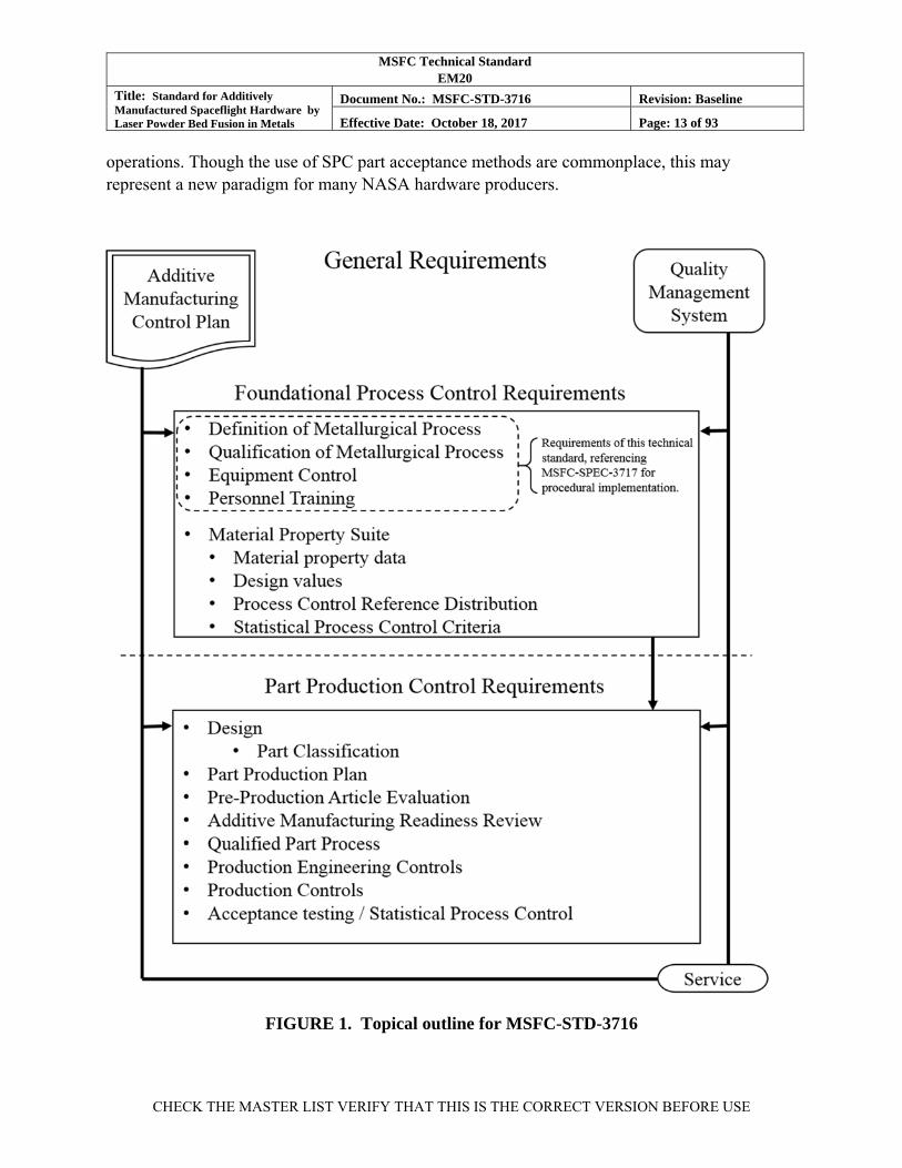
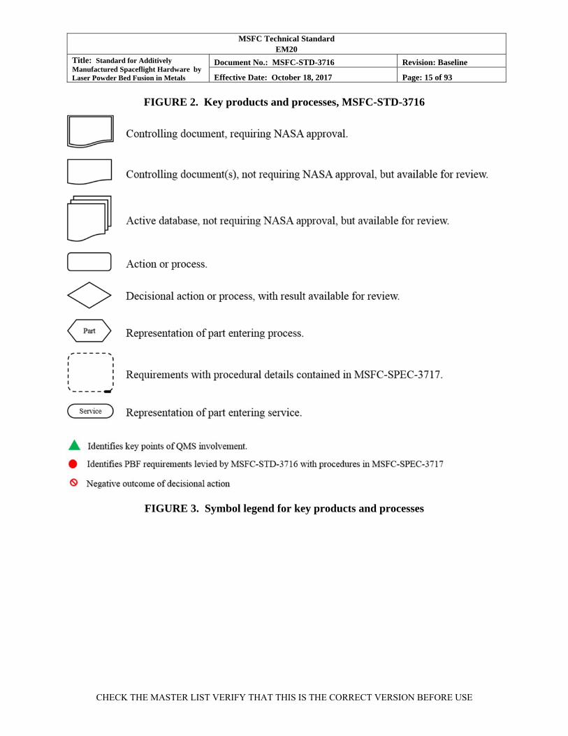
This MSFC Technical Standard provides the policy framework for the development and production of hardware produced using the L-PBF AM process to accommodate requirements from NASA’s governing design and safety standards and to provide necessary controls for the safe implementation of the technology. It does not dictate structural design criteria. Figures 1, 2, & 3 provide an outline and illustrate the key products and processes controlled by this MSFC Technical Standard and, figuratively, how each is related.
Figure 1, Topical outline for MSFC-STD-3716, summarizes the organization of this MSFC Technical Standard beginning with the general requirements for an AMCP to govern the engineering and production practice in parallel with an active Quality Management System (QMS) to provide quality assurance, from establishing the foundational processes to placing the part into service. The foundational process control requirements for L-PBF provide the basis for reliable part design and production. They include qualification of metallurgical processes, equipment controls, personnel training, and material property development. The part production control requirements are typical of aerospace operations and include design and assessment controls, PPPs, pre-production article processes, and relevant production controls.
Figure 2, Key Products and processes, MSFC-STD-3716, provides a more detailed view of this outline by illustrating the key products and processes of this MSFC Technical Standard. The symbols used in the figure indicate the type of product or action such as internal documents, documents requiring approval, databases, or decisional actions. The legend for these symbols is given in Figure 3, Symbol Legend for Key Products and Processes. Structured similarly to the outline in Figure 1, Figure 2 further illustrates the flow of the products and processes through the general, foundational, and part production controls. While showing the figurative relationships of the key products and processes, Figure 2 cannot be read as a serial flow chart, particularly in the prerequisite foundational controls.
Beginning at the top of Figure 2 with the general requirements, the implementation of the policies of this MSFC Technical Standard, and any tailoring that may be required, is enforced through the AMCP prepared by the CEO responsible for development and implementation of the L-PBF parts. The AMCP also defines how the QMS(s) is integrated throughout the process. Key points of QMS integration are illustrated with a green triangle symbol in Figure 2. The AMCP and the QMS govern the engineering and quality assurance disciplines, respectively, from start to finish.

MSFC Technical Standard EM20
Title: Standard for Additively Manufactured Spaceflight Hardware by Laser Powder Bed Fusion in Metals
Document No.: MSFC-STD-3716 Revision: Baseline
Effective Date: October 18, 2017 Page: 11 of 93
CHECK THE MASTER LIST VERIFY THAT THIS IS THE CORRECT VERSION BEFORE USE
The foundational process control requirements include methodologies for L-PBF process qualification, control and operation of equipment, personnel training, and the characterization of L-PBF material performance for design values and future statistical process control (SPC) monitoring. This MSFC Technical Standard defines the foundational process control requirements; however, the procedural requirements to implement metallurgical process qualification, equipment control, and training are delegated to a companion specification: MSFC-SPEC-3717, Specification for Control and Qualification of Laser Powder Bed Fusion Metallurgical Processes. The dashed-line box of Figure 2 contains the content implemented through MSFC-SPEC-3717 for basic control and qualification of the L-PBF process. For metallurgical process control, the key steps include establishing a Qualified Metallurgical Process (QMP) to the requirements of a Master QMP to ensure a consistent process definition, using a specification to control the raw material powder feedstock, evaluating the process capability and, finally, documenting the process capability in a configuration-controlled QMP record (QMP/R) for each L-PBF machine.
Qualified machines and trained operators are key foundational controls required by this MSFC Technical Standard and implemented through MSFC-SPEC-3717. Though represented independently in Figure 2, they are essential to any successful L-PBF operation; thus, plans are required to define how controls are implemented. An Equipment and Facility Control Plan (EFCP), the basic contents of which are defined by the specification, is developed and maintained by any facility producing L-PBF parts. The EFCP sets and enforces the requirements for qualification, maintenance, and calibration activities on L-PBF machines and associated equipment. Equipment controls are only as good as the training of its operators. The specification defines acceptable personnel training protocols to be implemented and tracked through QMS records.
The policy and procedures governing the development of L-PBF material properties remain within this MSFC Technical Standard and are controlled in the context of a Material Property Suite (MPS). The MPS concept includes three entities: first, an actively maintained database of material property values; second, a sub-set of that database used to derive and implement a Process Control Reference Distribution (PCRD), which provides a set of SPC criteria for witness test evaluation; and third, an actively maintained set of material design values to support the part design process. Integrating simple SPC concepts to monitor the process and substantiate the integrity of design values is a unique aspect of the standard required to accommodate the process-sensitive nature of L-PBF.
Once the foundational process controls are established, the process of design and production of L-PBF parts can occur. The flow of operations required for L-PBF part production, shown in the lower half of Figure 2, is typical of most aerospace hardware production. There are only a few aspects to this design and production process flow having unique controls for AM. These are identified in the following description.
MSFC Technical Standard EM20
Title: Standard for Additively Manufactured Spaceflight Hardware by Laser Powder Bed Fusion in Metals
Document No.: MSFC-STD-3716 Revision: Baseline
Effective Date: October 18, 2017 Page: 12 of 93
CHECK THE MASTER LIST VERIFY THAT THIS IS THE CORRECT VERSION BEFORE USE
When a part is identified as a candidate for L-PBF production, the part design has to be made compatible with the AM process. This can be non-trivial, and this MSFC Technical Standard does not prescribe L-PBF design practice—it provides only high-level guidance to caution against common pitfalls. This MSFC Technical Standard does influence the design process, however, through policies regarding fracture control, part qualification, and the use of the MPS for design properties specific to the L-PBF material product form.
Once a part design and assessment nears maturity, a classification system is used to assess the risk associated with the part. Parts are classified on their consequence of failure, structural demand, and L-PBF risk, which accounts for part inspection feasibility and L-PBF build sensitivities. The part classification is used to communicate part risk consistently and to set commensurate levels of control. A consistent, standardized classification system is important to enable NASA to maintain consistent policies and mitigations for risk both within and across programs using L-PBF parts.
The requirement to develop a PPP is one aspect of this production flow that may be considered unique due to the AM process. The PPP serves as a companion to the part drawing and documents the rationale for, and implementation of, the production methodology, including such items as part build orientation, appropriate QMP, witness test requirements, inspection methods and limitations, and proof testing methodology. The PPP is a deliverable product requiring NASA approval prior to proceeding into production; therefore, the PPP needs to convey succinctly the full design and production intent of the part. Once approved, the combination of drawing and PPP serve as the basis for establishing the complete engineering production controls.
The PPP may specify the pre-production article process or delegate that to a stand-alone pre-production article plan. The pre-production article process is executed with rigor and, once complete, leads to an additive manufacturing readiness review (AMRR) of the pre-production article report, the drawing, the QMP, and all preliminary engineering production controls used to obtain the pre-production article. If the AMRR is deemed successful, the entire candidate process for part production, including drawings, electronic files, and production engineering steps and sequences become locked, version controlled, and guarded against changes. This locked state defines a Qualified Part Process (QPP), which is then used to control part production.
A number of process verifications are required following, or concurrent with, the final stages of part production. These verifications form the evidence for part acceptance to the defined design state. At a minimum, these verifications typically include a review of available build logs and related content used to substantiate process control, dimensional inspections, non-destructive inspections of surface and volumetric integrity, proof testing, and testing of witness materials produced during the build process. Evaluation of witness specimens provides evidence of systemic process control through statistical comparison to defined performance metrics developed as part of the MPS. This MSFC Technical Standard allows for witness testing schemes based on individual part acceptance or as an ongoing SPC methodology for continuous
MSFC Technical Standard EM20
Title: Standard for Additively Manufactured Spaceflight Hardware by Laser Powder Bed Fusion in Metals
Document No.: MSFC-STD-3716 Revision: Baseline
Effective Date: October 18, 2017 Page: 13 of 93
CHECK THE MASTER LIST VERIFY THAT THIS IS THE CORRECT VERSION BEFORE USE
operations. Though the use of SPC part acceptance methods are commonplace, this may represent a new paradigm for many NASA hardware producers.
FIGURE 1. Topical outline for MSFC-STD-3716

MSFC Technical Standard EM20
Title: Standard for Additively Manufactured Spaceflight Hardware by Laser Powder Bed Fusion in Metals
Document No.: MSFC-STD-3716 Revision: Baseline
Effective Date: October 18, 2017 Page: 14 of 93
CHECK THE MASTER LIST VERIFY THAT THIS IS THE CORRECT VERSION BEFORE USE
[WBM(1]
MSFC Technical Standard EM20
Title: Standard for Additively Manufactured Spaceflight Hardware by Laser Powder Bed Fusion in Metals
Document No.: MSFC-STD-3716 Revision: Baseline
Effective Date: October 18, 2017 Page: 15 of 93
CHECK THE MASTER LIST VERIFY THAT THIS IS THE CORRECT VERSION BEFORE USE
FIGURE 2. Key products and processes, MSFC-STD-3716
FIGURE 3. Symbol legend for key products and processes
MSFC Technical Standard EM20
Title: Standard for Additively Manufactured Spaceflight Hardware by Laser Powder Bed Fusion in Metals
Document No.: MSFC-STD-3716 Revision: Baseline
Effective Date: October 18, 2017 Page: 16 of 93
CHECK THE MASTER LIST VERIFY THAT THIS IS THE CORRECT VERSION BEFORE USE
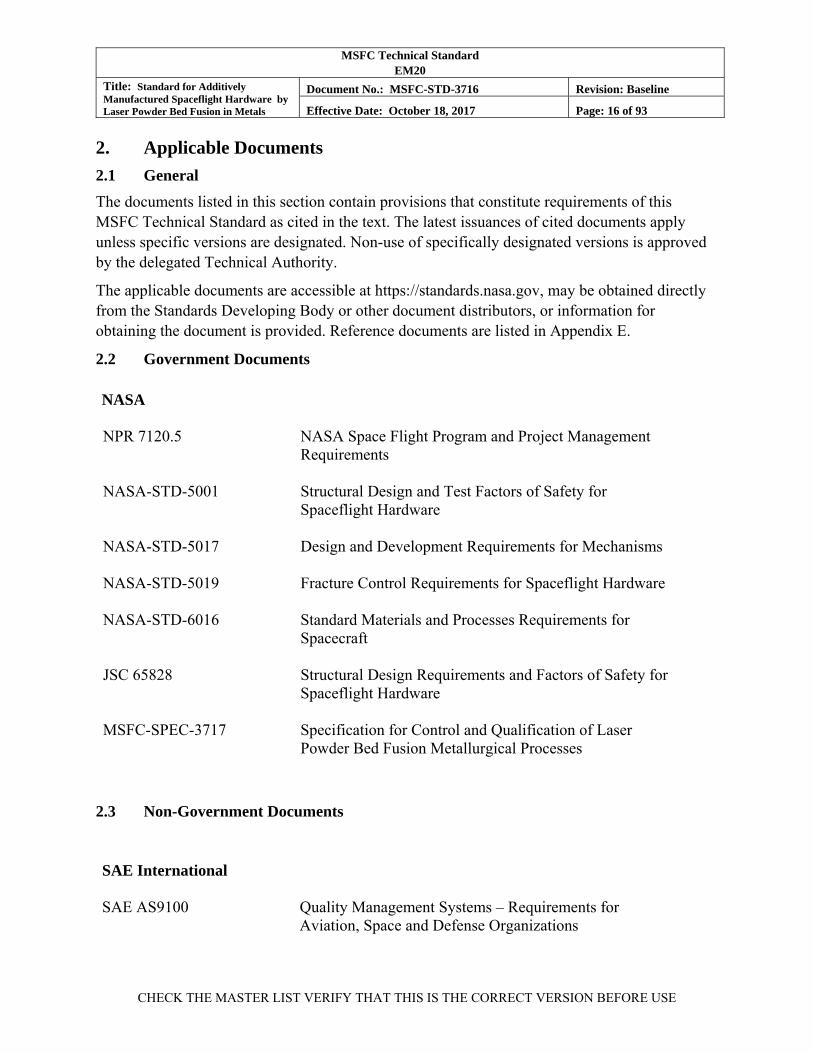
2. Applicable Documents
2.1 General
The documents listed in this section contain provisions that constitute requirements of this MSFC Technical Standard as cited in the text. The latest issuances of cited documents apply unless specific versions are designated. Non-use of specifically designated versions is approved by the delegated Technical Authority.
The applicable documents are accessible at https://standards.nasa.gov, may be obtained directly from the Standards Developing Body or other document distributors, or information for obtaining the document is provided. Reference documents are listed in Appendix E.
2.2 Government Documents
NASA
NPR 7120.5 NASA Space Flight Program and Project Management
Requirements
NASA-STD-5001 Structural Design and Test Factors of Safety for Spaceflight Hardware
NASA-STD-5017 Design and Development Requirements for Mechanisms
NASA-STD-5019 Fracture Control Requirements for Spaceflight Hardware
NASA-STD-6016 Standard Materials and Processes Requirements for Spacecraft
JSC 65828 Structural Design Requirements and Factors of Safety for Spaceflight Hardware
MSFC-SPEC-3717 Specification for Control and Qualification of Laser Powder Bed Fusion Metallurgical Processes
2.3 Non-Government Documents
SAE International SAE AS9100 Quality Management Systems – Requirements for
Aviation, Space and Defense Organizations
MSFC Technical Standard EM20
Title: Standard for Additively Manufactured Spaceflight Hardware by Laser Powder Bed Fusion in Metals
Document No.: MSFC-STD-3716 Revision: Baseline
Effective Date: October 18, 2017 Page: 17 of 93
CHECK THE MASTER LIST VERIFY THAT THIS IS THE CORRECT VERSION BEFORE USE
2.4 Governing NASA Standards
[AMR-2] Additively manufactured parts shall comply with the intent of all governing standards levied upon the project.
[Rationale: This requirement precludes the misconception that silence or lack of specificity regarding AM or L-PBF in other governing standards implies those requirements do not apply to L-PBF parts.]
The novelty and uniqueness of L-PBF parts and the L-PBF process provide no exemption from these requirements. The requirements of this MSFC Technical Standard are employed in addition to these broader requirements to control aspects that are specific to L-PBF parts and the process where the governing standards are silent. The requirements of this MSFC Technical Standard, where differing from those of higher governing standards, may be used to meet the intent of those requirements.
See commentary for Section 2.4 in Appendix B.
3. Acronyms, Abbreviations, Symbols, and Definitions
3.1 Acronyms, Abbreviations, and Symbols
% Percent
A2LA American Association for Laboratory Accreditation
AM Additive Manufacturing (and variants)
AMCP Additive Manufacturing Control Plan
AMR Additive Manufacturing Requirement
AMRR Additive Manufacturing Readiness Review
CAD Computer-Aided Design
CEO Cognizant Engineering Organization
CH Cryptographic Hash
CIFS Critical Initial Flaw Size
CV Coefficient of Variation
DOT Department of Transportation
DPD Digital Product Definition
DRD Data Requirements Description
EFCP Equipment and Facility Control Plan
FAA Federal Aviation Administration
MSFC Technical Standard EM20
Title: Standard for Additively Manufactured Spaceflight Hardware by Laser Powder Bed Fusion in Metals
Document No.: MSFC-STD-3716 Revision: Baseline
Effective Date: October 18, 2017 Page: 18 of 93
CHECK THE MASTER LIST VERIFY THAT THIS IS THE CORRECT VERSION BEFORE USE
FIPS Federal Information Processing Standard
FMEA Failure Modes and Effects Analysis
HCF High Cycle Fatigue
HIP Hot Isostatic Pressing
IEST Institute of Environmental Sciences and Technology
in inch(es)
ISO International Organization for Standardization
JSC Johnson Space Center
L-PBF Laser-Powder Bed Fusion
mm millimeter(s)
MMPDS Metallic Materials Properties Development and Standardization
MPS Material Property Suite
MRB Material Review Board
MUA Materials Usage Agreement
NASA National Aeronautics and Space Administration
NDE Non-destructive Evaluation
NPD NASA Policy Directive
NPR NASA Procedural Requirements
PBF Powder Bed Fusion
PCRD Process Control Reference Distribution
PPP Part Production Plan
PUB Publication
QMP Qualified Metallurgical Process
QMP/R Qualified Metallurgical Process Record
QMS Quality Management System
QPP Qualified Part Process
RFCB Responsible Fracture Control Board
SHA Secure Hash Algorithm
SHS Secure Hash Standard
MSFC Technical Standard EM20
Title: Standard for Additively Manufactured Spaceflight Hardware by Laser Powder Bed Fusion in Metals
Document No.: MSFC-STD-3716 Revision: Baseline
Effective Date: October 18, 2017 Page: 19 of 93
CHECK THE MASTER LIST VERIFY THAT THIS IS THE CORRECT VERSION BEFORE USE
SPC Statistical Process Control
SPEC Specification
STD Standard
STL Stereolithography (file format)
UTS Ultimate Tensile Strength
3.2 Definitions
Additive Manufacturing: Process of creating objects from three-dimensional computer models incrementally, typically layer by layer, from material stock. This is contrasted with subtractive manufacturing technologies that remove material to create the object, such as machining. Adj., additively manufactured
Additive Manufacturing Readiness Review: An integrated engineering review of the maturity of all manufacturing controls for an L-PBF part to confirm that all necessary process controls and production engineering are in place to produce a part that fully and reliably meets the certified design state. At a minimum, the AMRR team includes individuals cognizant of the part from the disciplines of design, structural assessment, materials and processes, additive manufacturing production, and safety and mission assurance. A successful, documented AMRR demarcates the production process of the part becoming a QPP.
Build: A single, complete operation of the powder bed fusion process to create objects in the powder bed. Multiple objects are commonly created during a build.
Build Area: The area in the build plane where the fusion process is controlled and qualified to a QMP per MSFC-SPEC-3717. The build area may be defined smaller than the full reach of the laser if needed to maintain the quality level of the fusion process.
Build Box/Build Volume: The volume in which parts may be reliably produced in the powder bed. The build volume is defined by the build area and maximum height of the build.
Build Lot: All objects created during a single build operation.
Build Plane: Plane in which fusion takes place during powder bed fusion. Commonly, the build plane is fixed and the build platform is incrementally lowered to create the powder bed.
Build Platform: Flat, solid material base upon which powder bed fusion objects are built.
Catastrophic Hazard: The presence of a risk situation that could directly result in loss of life, disabling injury, or loss of a major national asset.
Certified Design State: A complete, stable design state that has been reviewed and verified as meeting all levied requirements to safely and reliably complete the intended mission.
Continuous Production Build: Any build within a continuous series where each build and the L-PBF machine is monitored and tracked in accordance with all SPC requirements of Section

MSFC Technical Standard EM20
Title: Standard for Additively Manufactured Spaceflight Hardware by Laser Powder Bed Fusion in Metals
Document No.: MSFC-STD-3716 Revision: Baseline
Effective Date: October 18, 2017 Page: 20 of 93
CHECK THE MASTER LIST VERIFY THAT THIS IS THE CORRECT VERSION BEFORE USE
6.2.2.3, “Continuous Production Build SPC Requirements.” Continuous Production Builds have reduced witness sampling requirements; thus, they rely upon an integrated performance history of prior and subsequent builds, and periodic SPC qualification builds, to substantiate process control rationale. A series of Continuous Production Builds may include a variety of builds for different parts.
Cognizant Engineering Organization: The organization responsible for establishing/maintaining the certified design state of the hardware and delivering hardware compliant with all levied requirements.
Design State: Collection of all information required to define a part design, produce parts compliant with the design, verify parts are compliant with the design, and information and evidence needed to confirm the design is compliant with all operational and safety requirements.
Design Value Margin: The difference between the established design value and the T99 value of the distribution fit to the substantiating data. Design Value Margin = (T99 – Design Value) / [(T99 + Design Value)/2]. See Figure 5, Substantiation of design value from MPS data, in Appendix C.
Fatigue Limit: A cyclic stress or strain range below which fatigue initiation failures are unlikely at a defined number of cycles based on fatigue testing. The fatigue limit is commonly defined at a pragmatic cycle count appropriate for the hardware, often 107 or 108 cycles. For the context of this MSFC Technical Standard, a fatigue limit is defined to be ≥107 cycles. At this time, additively manufactured materials (L-PBF) are not considered to have an endurance limit (a cyclic stress level below which fatigue life is infinite).
Heat Treat Lot: All objects subjected to a complete heat treatment sequence at the same time in the same equipment.
Independent Build: Any L-PBF build that is not part of a Continuous Production Build series. Independent builds have additional witness specimen requirements that improve the ability to evaluate the SPC quality of the build independent of the results of prior or subsequent builds from the L-PBF machine.
L-PBF Process Vendor: The entity responsible for production of powder bed fusion parts to meet the requirements of the certified design state. The L-PBF process vendor may be synonymous with the CEO or a sub-vendor to the CEO.
Nadcap™: Formerly NADCAP (National Aerospace and Defense Contractors Accreditation Program), a global cooperative accreditation program for aerospace engineering, defense, and related industries.
Material Property Suite (MPS): An actively maintained collection of L-PBF material property information specific to an alloy and condition that includes material test data, design values, and criteria needed to implement and maintain SPC for the L-PBF process.

MSFC Technical Standard EM20
Title: Standard for Additively Manufactured Spaceflight Hardware by Laser Powder Bed Fusion in Metals
Document No.: MSFC-STD-3716 Revision: Baseline
Effective Date: October 18, 2017 Page: 21 of 93
CHECK THE MASTER LIST VERIFY THAT THIS IS THE CORRECT VERSION BEFORE USE
MPS, Lot-Mature: an MPS that contains data from a minimum of five (5) unique powder feedstock lots and ten (10) build and heat treat lots with a nominally balanced distribution across lot data used for all design values that require bounding with statistical significance. Properties using a typical basis may be considered Lot-Mature with fewer lots as noted in Section 7. A Lot-Mature MPS has sufficient variability incorporated to allow the use of design values to be applied to parts of all classes built with powder feedstock lots equivalently controlled by an applicable, registered QMP. See Section 5.4.2.1 and the definition for Lot-Provisional MPS.
MPS, Lot-Provisional: an MPS that contains data from fewer than five (5) unique powder feedstock lots and ten (10) build and heat treat lots and/or does not demonstrate the nominally balanced distribution across a sufficient number of lots of data to be considered a Lot-Mature MPS. A Provisional MPS has restrictions on use as required in Section 5.4.2.1. See definition for Lot-Mature MPS.
Part: Fundamental unit or object defined by the design state. A qualified part process may include multiple parts in a build.
Powder Bed Fusion: An additive manufacturing process that uses a high-energy source to selectively fuse, layer-by-layer, portions of a powder bed.
Powder Lot (also powder blend lot): A quantity of powder supplied by a certified powder producer that was manufactured by the same process and equipment, and blended simultaneously. The blended powder lot may contain multiple heats of powder when all heats independently meet the powder specification.
Self-supporting Structure (unsupported limit): Part features that may be built in an overhanging condition without the need for support structure below it. The maximum angle at which overhanging part features may be reliably built without supporting structure is the unsupported limit.
Support Structure: Supplementary, sacrificial material built along with a part used to anchor overhanging geometry, provide dimensional stability, and promote proper thermal management within the powder bed during a build.
T99: Designation for the lower tolerance bound of a statistical distribution fit to material property data indicating at least 99 percent (%) of the population equals or exceeds this value with a confidence of 95%. See the Metallic Materials Properties Development and Standardization (MMPDS) for further information.
Unique Build/Heat Treat Lots (material property lot requirements): Material that does not have either build or heat treat lot commonality.
Witness Line: A visual demarcation along build layer planes indicating a change in steady-state operation of the powder bed fusion process. The demarcation may be a geometry shift, change in surface texture, change in coloration, or any other distinct non-uniformity.
MSFC Technical Standard EM20
Title: Standard for Additively Manufactured Spaceflight Hardware by Laser Powder Bed Fusion in Metals
Document No.: MSFC-STD-3716 Revision: Baseline
Effective Date: October 18, 2017 Page: 22 of 93
CHECK THE MASTER LIST VERIFY THAT THIS IS THE CORRECT VERSION BEFORE USE
To the extent possible, this MSFC Technical Standard uses terminology as established by, or consistent with, international standards organizations. See ISO/ASTM 52921, Standard Terminology for Additive Manufacturing-Coordinate Systems and Test Methodologies.
4. General Requirements
4.1 Additive Manufacturing Control Plan
[AMR-3] The CEO responsible for the design and manufacture of L-PBF hardware shall provide an AMCP that accomplishes each of the following:
a. Documents the implementation of each of the requirements of this MSFC Technical Standard.
b. Documents and provides rationale for any tailoring of the requirements of this MSFC Technical Standard.
c. Documents the methods used to control compliance with these requirements by subcontractors and vendors.
d. Provides for complete governance for the implementation of L-PBF such that, once approved by the procuring authority, the AMCP becomes the document used for verification of L-PBF requirements.
[Rationale: The AMCP is necessary to document the decisions made in the implementation of this MSFC Technical Standard and becomes the governing document for the CEO regarding L-PBF requirements.]
The AMCP may be provided as an independent document or as part of the Materials and Processes Selection, Control and Implementation Plan per NASA-STD-6016 and may reference controlling content in other approved, governing plans such as the Fracture Control Plan per NASA-STD-5019, Fracture Control Requirements for Spaceflight Hardware; Structural Assessment Plan per NASA-STD-5012, Strength and Life Assessment Requirements for Liquid Fueled Space Propulsion System Engines; or the Structural Verification Plan per JSC 65828, Structural Design Requirements and Factors of Safety for Spaceflight Hardware.
4.2 Quality Management System
[AMR-4] The CEO shall ensure a QMS conforming to SAE AS9100, Quality Management Systems – Requirements for Aviation, Space and Defense Organizations, or an approved equivalent, is in place and active at all entities involved in the design and production of L-PBF hardware.
[Rationale: A QMS is required to ensure necessary process controls and mitigate risks associated with non-compliance. The AS9100 QMS requirement is enforced because the L-
MSFC Technical Standard EM20
Title: Standard for Additively Manufactured Spaceflight Hardware by Laser Powder Bed Fusion in Metals
Document No.: MSFC-STD-3716 Revision: Baseline
Effective Date: October 18, 2017 Page: 23 of 93
CHECK THE MASTER LIST VERIFY THAT THIS IS THE CORRECT VERSION BEFORE USE
PBF process is considered “complex” per NPD 8730.5, NASA Quality Assurance Program Policy, due to significant reliance on process controls for the reliability of the product. L-PBF parts in Class A are also considered “critical” per NPD 8730.5.]
4.3 Vendor Compliance
[AMR-5] The CEO shall ensure all vendor-provided products and services are compliant with this MSFC Technical Standard as implemented by the AMCP and ensured through an applicable QMS.
[Rationale: The CEO is expected to rely upon vendors for aspects of producing L-PBF parts. The quality of parts may be compromised at any stage of the process. This requirement precludes the use of vendors whose products or services are not compliant with the controls of this MSFC Technical Standard.]
This vendor requirement is not limited to the L-PBF Process Vendor but extends to all potential vendors and sub-vendors involved in the process of designing and producing L-PBF parts. For example, vendors providing part processing or witness testing (such as heat treating, mechanical testing, or chemical analysis) are expected to be approved by the CEO and accredited through Nadcap™, the American Association for Laboratory Accreditation (A2LA), or other nationally accepted accreditation body.
See additional commentary on the roles of the CEO and L-PBF process vendor in Appendix B.
5. Foundational Process Control Requirements
5.1 Qualified Metallurgical Process
[AMR-6] All L-PBF parts shall be produced to a QMP developed in accordance with MSFC-SPEC-3717.
[Rationale: L-PBF process qualification is required to establish and maintain control of the process.]
5.2 Equipment Control
[AMR-7] All equipment integral to the L-PBF process shall be under the control of an EFCP developed in accordance with MSFC-SPEC-3717.
[Rationale: Proper qualification, calibration, and maintenance of L-PBF equipment and its associated equipment are essential to production of reliable L-PBF hardware.]
5.3 Personnel Training
[AMR-8] Personnel operating L-PBF equipment, or in other roles with direct influence on the L-PBF process, shall have training certification in accordance with MSFC-SPEC-3717.

MSFC Technical Standard EM20
Title: Standard for Additively Manufactured Spaceflight Hardware by Laser Powder Bed Fusion in Metals
Document No.: MSFC-STD-3716 Revision: Baseline
Effective Date: October 18, 2017 Page: 24 of 93
CHECK THE MASTER LIST VERIFY THAT THIS IS THE CORRECT VERSION BEFORE USE
[Rationale: Properly trained personnel are essential to reliable operation of L-PBF equipment and facilities.]
Examples of other roles with direct influence on the L-PBF process may include preparation of electronic build files, or evaluation of L-PBF as-built microstructure.
5.4 Material Property Requirements
[AMR-9] Material properties specific to each L-PBF alloy and condition shall be developed and maintained as an MPS by the CEO in accordance with the following:
a. Documentation substantiating the development, implementation, and maintenance of the MPS is submitted for review and approval through the Materials Usage Agreement (MUA) process of NASA-STD-6016, or other accepted review and approval mechanism.
b. Material property design values, PCRDs, and the supporting data of the MPS are made available for NASA review as requested.
[Rationale: Material properties specific to the L-PBF product form and its unique characteristics are required for reliable structural design assessment. Maintaining a suite of design values and its supporting data provides the basis for criteria used to monitor process control.]
In this MSFC Technical Standard, material properties have a role in both design and process control and are maintained as an MPS. The MPS consists of four entities:
1. Material property data developed for a specific L-PBF alloy and material condition,
2. The design values derived from the data used in structural assessment,
3. PCRDs derived from the data to describe the material’s nominal performance and variability, and
4. SPC criteria based on the PCRD used in evaluating the L-PBF process to ensure the integrity of the design values is maintained.
The collection of mechanical properties in this MSFC Technical Standard was given a unique name, MPS, because it serves two purposes: creating a reference of expected performance for use in process control, and establishing design values. For conventional materials, the statistical relationship between process control and design values is evaluated at a moment in time, and rarely re-examined. In contrast, in the methodology of this MSFC Technical Standard, new process control data are continuously monitored and compared with the reference data to demonstrate that the process is not creeping. Activities that use this monitoring include lot witness testing, new machine equivalency testing, requalification of machines after maintenance, and machine or process upgrades.
When developed as required by this MSFC Technical Standard and implemented in conjunction with ongoing process control monitoring schemes, the design values in the
MSFC Technical Standard EM20
Title: Standard for Additively Manufactured Spaceflight Hardware by Laser Powder Bed Fusion in Metals
Document No.: MSFC-STD-3716 Revision: Baseline
Effective Date: October 18, 2017 Page: 25 of 93
CHECK THE MASTER LIST VERIFY THAT THIS IS THE CORRECT VERSION BEFORE USE
MPS meet the intent of the requirements for material property reliability for use in structural analysis.
5.4.1 Process Control in Material Property Development
[AMR-10] Process controls shall be enforced on L-PBF builds used for material characterization, including the use of a QMP and witness testing with specimens and acceptance criteria equivalent to a Class B1 part.
[Rationale: Material properties are reliable only if generated on material produced under defined and controlled processes.]
An L-PBF characterization build is defined as any build used to produce material to support the population of the MPS for a given L-PBF process or for developing process control baseline data. A controlled L-PBF process is a prerequisite to the development of material properties; therefore, characterization builds follow a QMP developed per MSFC-SPEC-3717. (See also QMP Bootstrapping in MSFC-SPEC-3717.) The process control requirements and prerequisites for producing L-PBF materials for characterization are similar to those required for parts. See section 6.1.1 on part classification.
5.4.2 Incorporating Sources of Variability in L-PBF Material Characterization
There are numerous sources of potential variability in L-PBF materials. This section identifies and attempts to mitigate common concerns with L-PBF material: powder feedstock lot variability, powder feedstock reuse limits, anisotropy, and L-PBF process influence factors, such as as-built surfaces and thin sections.
5.4.2.1 Lot Requirements and MPS Maturity
[AMR-11] The MPS shall incorporate powder feedstock lot variability and be identified as either a Lot-Mature MPS or a Lot-Provisional MPS based upon the number of lots represented (see Section 3.2, Definitions), such that:
a. Design values from a Lot-Mature MPS are applicable to parts of all classes built with powder feedstock lots equivalently controlled by an applicable, registered QMP;
b. Design values from a Lot-Provisional MPS are only applicable to parts of Class B built with a powder feedstock lot directly represented in the MPS and an approved, part-specific MUA.
[Rationale: Variations in powder feedstock, even within specification limits, result in variability in performance of material produced by the L-PBF process; therefore, this source of variability has to be incorporated into design values for reliable structural assessment.]

MSFC Technical Standard EM20
Title: Standard for Additively Manufactured Spaceflight Hardware by Laser Powder Bed Fusion in Metals
Document No.: MSFC-STD-3716 Revision: Baseline
Effective Date: October 18, 2017 Page: 26 of 93
CHECK THE MASTER LIST VERIFY THAT THIS IS THE CORRECT VERSION BEFORE USE
A Lot-Provisional MPS, containing fewer lots than that required for a Lot-Mature MPS, may be used for Class B parts with an approved, part-specific MUA. To be approved, the MUA is expected to substantiate that the Lot-Provisional MPS has a quantity of data sufficient to make an informed engineering assessment of the quality and statistical significance of the design values. The MUA is expected to demonstrate that the feedstock lot used in production of parts has a meaningful representation in the MPS, typically taken as a minimum of 15% of the population.
See further commentary for section 5.4.2.1 concerning lot maturity and MPS evolution in Appendix B.
5.4.2.2 Used Powder Lot Controls
[AMR-12] Limiting metrics for powder feedstock reuse shall be established and enforced to ensure the following:
a. The effects of reuse on material performance are either demonstrated as negligible or material property data representing the limiting reuse state are incorporated directly into the MPS population;
b. Parts are not build with powder feedstock exceeding the limiting reuse metrics;
c. The methodology for incorporating the influence of powder feedstock reuse into the design values of the MPS is described as part of the MUA substantiating the MPS methodology per section 5.4.
[Rationale: The L-PBF process has the potential to degrade powder feedstock with reuse by introducing contaminants, such as oxygen or combustion by-products, and changing the powder’s morphology and rheology characteristics; therefore, an understanding of powder reuse effects is required and the L-PBF process is to be controlled to preclude powder reuse from affecting part quality.]
The effects of powder reuse are alloy-specific; therefore, the intent is to evaluate powder reuse effects on material properties using only material procured to the powder feedstock specification identified by the QMP.
The CEO, in collaboration with the L-PBF Process Vendor, is responsible for ensuring powder feedstock reuse metrics are defined and enforced in accordance with this requirement. The expectation is that the efficacy of the reuse metrics are substantiated through a dedicated test plan and subsequent data that characterizes the influence of powder feedstock reuse on material performance or demonstrates that powder at the limiting reuse metric has negligible influence on material performance.
5.4.2.3 Anisotropy
MSFC Technical Standard EM20
Title: Standard for Additively Manufactured Spaceflight Hardware by Laser Powder Bed Fusion in Metals
Document No.: MSFC-STD-3716 Revision: Baseline
Effective Date: October 18, 2017 Page: 27 of 93
CHECK THE MASTER LIST VERIFY THAT THIS IS THE CORRECT VERSION BEFORE USE
[AMR-13] The MPS shall include supporting data necessary to evaluate the anisotropy present in L-PBF material produced to an applicable QMP and the approach for incorporating anisotropy into design values, or rationale for a bounding isotropic assumption, described as part of the MUA substantiating the MPS methodology per section 5.4.
[Rationale: The L-PBF process creates material using a directional process where the likelihood of the process yielding anisotropic material is high unless controls are in place to minimize this effect; therefore, quantifying the effects of anisotropy and rendering appropriate design values is important to valid structural integrity assessment.]
To make anisotropy evaluations feasible, the build orientation should always be identified and maintained for all material property development activities.
The intent of metallurgical and thermal process requirements in MSFC-SPEC-3717 is to minimize anisotropy. Design values developed from the supporting data in the MPS are not required to be orientation specific if the values of the bounding orientation are used and anisotropy is demonstrated as negligible, typically accepted as a less than 5% difference in properties by orientation. If the anisotropy is not negligible, then orientation-specific properties are required and complexity in process and part qualification will follow.
See commentary for section 5.4.2.3 in Appendix B.
5.4.2.4 Influence Factors
[AMR-14] The MPS shall include an evaluation of any identified factor related to the L-PBF process and resulting material that has influence on the performance of the material and its associated design values, with each identified influence factor incorporated into the MPS and the methodology for evaluating its influence described as part of the MUA substantiating the MPS methodology per section 5.4.
[Rationale: L-PBF material and its performance cannot be separated from the nature of the L-PBF process itself; therefore, process influences that potentially result in material performance debits must be identified and incorporated into the MPS design values.]
Examples of influence factor evaluations expected in the MPS include:
a. Effects of surface texture, as-built or improved, on material performance as a function of build orientation, particularly in fatigue,
b. Effects of as-built surface texture on thin-section performance, including geometric effects of realized cross-section as well as mechanical property influence,
c. Effects of microstructure differences occurring spatially throughout a build due to powder bed thermal history, scan strategies, or inter-pass temperature influences,

MSFC Technical Standard EM20
Title: Standard for Additively Manufactured Spaceflight Hardware by Laser Powder Bed Fusion in Metals
Document No.: MSFC-STD-3716 Revision: Baseline
Effective Date: October 18, 2017 Page: 28 of 93
CHECK THE MASTER LIST VERIFY THAT THIS IS THE CORRECT VERSION BEFORE USE
d. Effects of the build process pause and restart allowance in the QMP–demonstration that effects are negligible on material performance, and,
e. Effects of test specimen geometry for non-standard configurations needed for evaluation of the influence factors or evaluation of material taken from parts such as in pre-production article evaluations.
These effects may be evaluated through ratio test methods as described in Section 7.2.1, or properties may be developed independently to accommodate these influence factors.
See commentary for section 5.4.2.4 in Appendix B.
5.4.3 Establishing Design Values
[AMR-15] Material property design values specific to each L-PBF alloy and condition shall be developed, or otherwise substantiated, according to the requirements and guidance of Section 7 for all applicable properties and environments required for structural assessment.
[Rationale: Material property design values will differ with L-PBF process and material condition; therefore, design values specific to each L-PBF alloy and condition have to be established to enable reliable structural assessment.]
5.4.3.1 Configuration Control of Design Values
[AMR-16] Material property design values shall be maintained under configuration control as an integral part of an MPS.
[Rationale: Design values are the end-product of an MPS that is made available to the design and analysis community; therefore, a methodology to maintain configuration control of the disseminated content is necessary to ensure reliable use of such content in design assessment.]
5.4.4 Criteria for the Use of External Data in the MPS
[AMR-17] Material property data generated outside the jurisdiction of this MSFC Technical Standard, such as prior industry or government data, shall meet each of the following criteria prior to incorporation into an MPS:
a. Properties are generated from material produced by the L-PBF process.
b. Authenticating records of traceability are available for the feedstock chemistry and heat treatment operations.
c. Properties are generated from material tested in a metallurgical condition (heat treatment and microstructure) equivalent to that defined by QMPs registered to the MPS.
MSFC Technical Standard EM20
Title: Standard for Additively Manufactured Spaceflight Hardware by Laser Powder Bed Fusion in Metals
Document No.: MSFC-STD-3716 Revision: Baseline
Effective Date: October 18, 2017 Page: 29 of 93
CHECK THE MASTER LIST VERIFY THAT THIS IS THE CORRECT VERSION BEFORE USE
d. Authenticating records of traceability are available that illustrate the material internal quality and final microstructure.
e. The geometry and build orientation of test specimens are defined.
f. The specifications governing the material test methods are defined.
g. The external data is provided in the form of actual test results to allow design values and PCRD criteria to be established or independently verified.
h. Demonstration that active QMP(s) produce material equivalent in microstructure and mechanical properties based on the registration process of MSFC-SPEC-3717.
i. An MUA documenting each of these criteria is approved.
[Rationale: The incorporation of prior databases for L-PBF material properties into an MPS will become standard practice as the technology matures. These criteria ensure the database contains sufficient information to follow the process controls required by this MSFC Technical Standard.]
5.4.5 Process Control Reference Distributions
[AMR-18] PCRDs for material properties used in witness specimen process control shall be established and maintained for each MPS.
[Rationale: Maintaining consistency of material performance for L-PBF is essential to structural integrity. To ensure this control is maintained for all L-PBF operations requires a reference definition of expected material performance by which process performance can be evaluated. The PCRD provides this reference.]
A PCRD defines the nominally expected performance of the L-PBF process for material produced using a QMP registered to that MPS. The PCRD also defines the acceptance criteria for evaluation of witness specimens used to monitor the L-PBF process. Nominally, four PCRDs are defined for each MPS: ultimate tensile strength (UTS), yield strength, elongation, and fatigue life at a fixed cyclic stress condition. The PCRDs and their associated acceptance criteria are documented as part of the MPS or as an independent record.
The type of distribution used for the PCRD is not dictated by this MSFC Technical Standard. The distribution should be chosen based on the quality of the distribution’s fit to the data. Any appropriate distribution and associated characteristic parameters may be used to define the PCRD.
Commentary on the use of the PCRD concept in process control witness sampling is discussed in section 6.2.2.4 of this MSFC Technical Standard.
MSFC Technical Standard EM20
Title: Standard for Additively Manufactured Spaceflight Hardware by Laser Powder Bed Fusion in Metals
Document No.: MSFC-STD-3716 Revision: Baseline
Effective Date: October 18, 2017 Page: 30 of 93
CHECK THE MASTER LIST VERIFY THAT THIS IS THE CORRECT VERSION BEFORE USE
See commentary for section 5.4.5 in Appendix B and an example of PCRC development in Appendix C.
5.4.5.1 PCRD Maintenance
[AMR-19] PCRDs shall be updated on a regular basis to incorporate new sources of data and maintain compatibility between the PCRDs and the design values in the MPS, with the methodology and intervals for updating the PCRDs documented and approved as part of the MUA substantiating the MPS methodology per Section 5.4.
[Rationale: The PCRDs associated with an MPS are intended to represent the current, evolving state of the data within the MPS, reflecting diversity as data is added. To accurately represent the state of the MPS, the PCRDs have to be updated and, given their use as acceptance criteria, the PCRDs have to maintain values that preserve the integrity of the design values in the MPS.]
PCRD updates are considered an integral part of ongoing L-PBF process control with new sources of data coming from ongoing witness testing or further characterization efforts.
The recommended interval for updating the PCRDs is three months with a review prompted whenever a witness set fails to meet the PCRD. Initially, lot variability may be lacking in the PCRD data set and adjustments may be expected. Careful review is warranted whenever a PCRD is adjusted. Witness specimen data that fail to meet the PCRD acceptance criteria need particular attention. As part of the review and disposition of the non-conformance associated with the witness test failure, the failing witness data need to be marked for inclusion or exclusion from the PCRC update process. Failing data associated with known, non-relevant process escapes such as mechanical testing errors may be excluded. Failing data associated with unique process escapes such as heat treating errors may be excluded if corrective actions are taken. Failing data that cannot be associated with an identified and corrected process escape should be included in the PCRD update unless specific rationale is available to warrant exclusion. This is particularly true if the failed witness specimens are associated with a build that is given a use-as-is disposition.
6. Part Design and Production Control Requirements
This section provides requirements governing the design, development, assessment, testing, and acceptance of L-PBF hardware. Topics include part classification, structural assessment, fracture control, the Integrated Structural Integrity Rationale, PPPs, the QPP, and policies governing control of model quality, build execution, and post-build operations.
6.1 Design for L-PBF
MSFC Technical Standard EM20
Title: Standard for Additively Manufactured Spaceflight Hardware by Laser Powder Bed Fusion in Metals
Document No.: MSFC-STD-3716 Revision: Baseline
Effective Date: October 18, 2017 Page: 31 of 93
CHECK THE MASTER LIST VERIFY THAT THIS IS THE CORRECT VERSION BEFORE USE
Accommodation of the unique aspects of the L-PBF process are required for successful L-PBF part design. Specific requirements for L-PBF design practice are not within the scope of this MSFC Technical Standard; however, requirements of this MSFC Technical Standard do play a role in the design process. This section identifies requirements that are incorporated during L-PBF part design and assessment.
Design for additive manufacturing is a newly developing discipline. AM designers must consider process factors beyond those common to traditional metallic design for subtractive manufacturing (machining). For example, reliability and performance of AM designs can be greatly influenced by subtle factors such as the surface finish in self-supporting structures. Beyond the motivations for design innovation, weight savings, and cost savings, AM designer objectives must include part reliability through minimizing support structures through self-supporting design, ease and verification of powder removal, design for inspection, design for adequacy of proof test, accommodating the AM build volume for parts and required witness specimens, allowance for finishing operations, and controlling surface texture or providing for access for surface texture improvement. The quality of an AM design is not judged based on its cost-savings, weight-savings, or geometric complexity alone but on all of the above elements that influence the practicality of reliable AM implementation.
6.1.1 Part Classification
[AMR-20] All AM parts shall be assigned a classification according to Figure 4 based upon consequence of failure, structural demand evaluated per Table I, and additive manufacturing risk evaluated per Table II.
[Rationale: Part classification is required to enable a consistent evaluation of part risk through defined metrics for consequence of failure, structural demand, and L-PBF associated risks. Without carefully defined part classes, the ability to efficiently and accurately gauge the risk associated with L-PBF parts within and across programs, projects, and suppliers is lost, resulting in risk mitigations that are either not commensurate or not consistent.]
The classification system establishes a consistent methodology to define and communicate the risk associated with L-PBF parts. Throughout this MSFC Technical Standard, these classifications determine appropriate levels of process control, qualification, and inspection. Figure 4, Part Classification, illustrates the classification system.
The part classification system uses a two-tier system to designate L-PBF parts based on relative risk. The alphabetical class is determined by consequence of failure, Class A being high, and Class B being low. The numerical subclasses of Classes A and B are determined by a combination of structural demand on the part and the risk associated with the L-PBF implementation for the part.
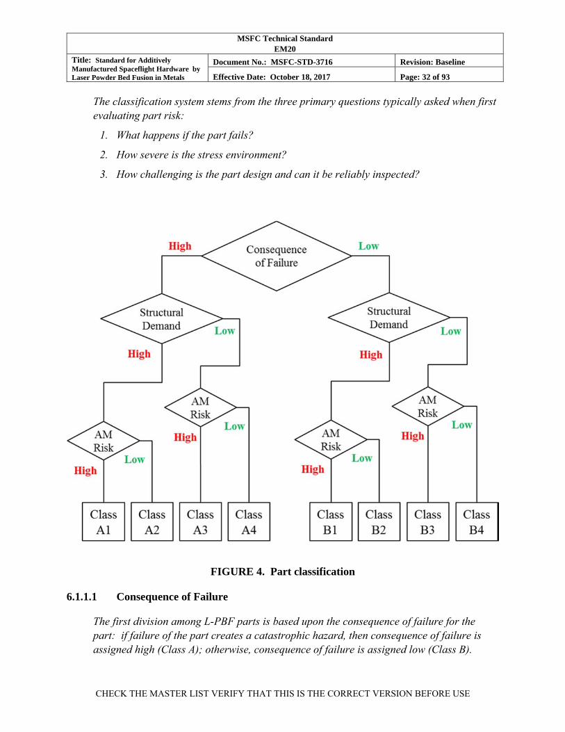
MSFC Technical Standard EM20
Title: Standard for Additively Manufactured Spaceflight Hardware by Laser Powder Bed Fusion in Metals
Document No.: MSFC-STD-3716 Revision: Baseline
Effective Date: October 18, 2017 Page: 32 of 93
CHECK THE MASTER LIST VERIFY THAT THIS IS THE CORRECT VERSION BEFORE USE
The classification system stems from the three primary questions typically asked when first evaluating part risk:
1. What happens if the part fails?
2. How severe is the stress environment?
3. How challenging is the part design and can it be reliably inspected?
FIGURE 4. Part classification
6.1.1.1 Consequence of Failure
The first division among L-PBF parts is based upon the consequence of failure for the part: if failure of the part creates a catastrophic hazard, then consequence of failure is assigned high (Class A); otherwise, consequence of failure is assigned low (Class B).
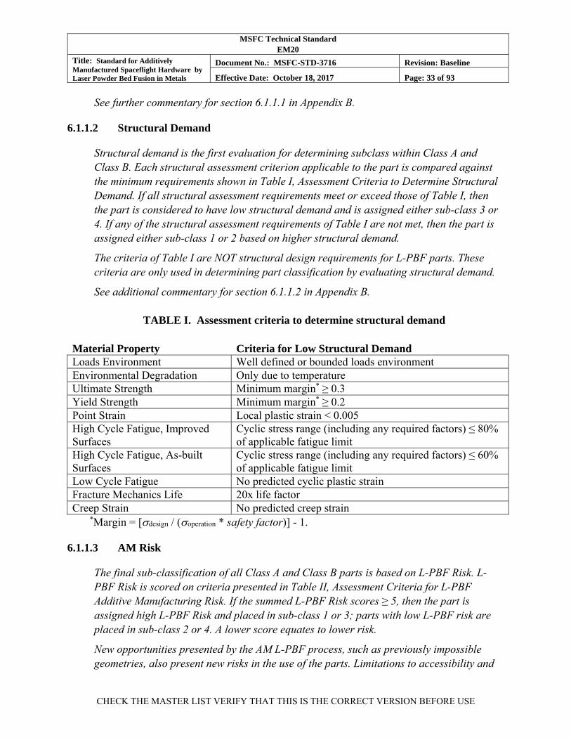
MSFC Technical Standard EM20
Title: Standard for Additively Manufactured Spaceflight Hardware by Laser Powder Bed Fusion in Metals
Document No.: MSFC-STD-3716 Revision: Baseline
Effective Date: October 18, 2017 Page: 33 of 93
CHECK THE MASTER LIST VERIFY THAT THIS IS THE CORRECT VERSION BEFORE USE
See further commentary for section 6.1.1.1 in Appendix B.
6.1.1.2 Structural Demand
Structural demand is the first evaluation for determining subclass within Class A and Class B. Each structural assessment criterion applicable to the part is compared against the minimum requirements shown in Table I, Assessment Criteria to Determine Structural Demand. If all structural assessment requirements meet or exceed those of Table I, then the part is considered to have low structural demand and is assigned either sub-class 3 or 4. If any of the structural assessment requirements of Table I are not met, then the part is assigned either sub-class 1 or 2 based on higher structural demand.
The criteria of Table I are NOT structural design requirements for L-PBF parts. These criteria are only used in determining part classification by evaluating structural demand.
See additional commentary for section 6.1.1.2 in Appendix B.
TABLE I. Assessment criteria to determine structural demand
Material Property Criteria for Low Structural Demand Loads Environment Well defined or bounded loads environment Environmental Degradation Only due to temperature Ultimate Strength Minimum margin* ≥ 0.3 Yield Strength Minimum margin* ≥ 0.2 Point Strain Local plastic strain < 0.005 High Cycle Fatigue, Improved Surfaces
Cyclic stress range (including any required factors) ≤ 80% of applicable fatigue limit
High Cycle Fatigue, As-built Surfaces
Cyclic stress range (including any required factors) ≤ 60% of applicable fatigue limit
Low Cycle Fatigue No predicted cyclic plastic strain Fracture Mechanics Life 20x life factor Creep Strain No predicted creep strain
*Margin = [design / (operation * safety factor)] - 1.
6.1.1.3 AM Risk
The final sub-classification of all Class A and Class B parts is based on L-PBF Risk. L-PBF Risk is scored on criteria presented in Table II, Assessment Criteria for L-PBF Additive Manufacturing Risk. If the summed L-PBF Risk scores ≥ 5, then the part is assigned high L-PBF Risk and placed in sub-class 1 or 3; parts with low L-PBF risk are placed in sub-class 2 or 4. A lower score equates to lower risk.
New opportunities presented by the AM L-PBF process, such as previously impossible geometries, also present new risks in the use of the parts. Limitations to accessibility and
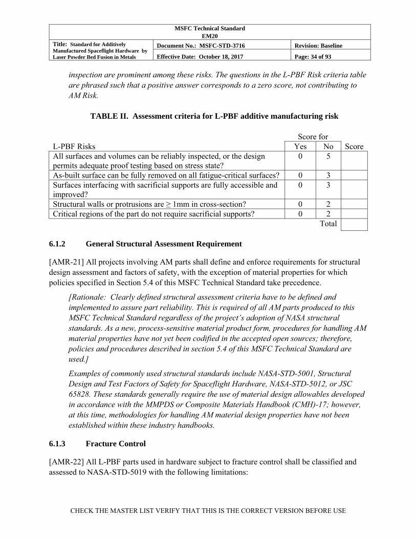
MSFC Technical Standard EM20
Title: Standard for Additively Manufactured Spaceflight Hardware by Laser Powder Bed Fusion in Metals
Document No.: MSFC-STD-3716 Revision: Baseline
Effective Date: October 18, 2017 Page: 34 of 93
CHECK THE MASTER LIST VERIFY THAT THIS IS THE CORRECT VERSION BEFORE USE
inspection are prominent among these risks. The questions in the L-PBF Risk criteria table are phrased such that a positive answer corresponds to a zero score, not contributing to AM Risk.
TABLE II. Assessment criteria for L-PBF additive manufacturing risk
Score for L-PBF Risks Yes No ScoreAll surfaces and volumes can be reliably inspected, or the design permits adequate proof testing based on stress state?
0 5
As-built surface can be fully removed on all fatigue-critical surfaces? 0 3 Surfaces interfacing with sacrificial supports are fully accessible and improved?
0 3
Structural walls or protrusions are ≥ 1mm in cross-section? 0 2 Critical regions of the part do not require sacrificial supports? 0 2 Total
6.1.2 General Structural Assessment Requirement
[AMR-21] All projects involving AM parts shall define and enforce requirements for structural design assessment and factors of safety, with the exception of material properties for which policies specified in Section 5.4 of this MSFC Technical Standard take precedence.
[Rationale: Clearly defined structural assessment criteria have to be defined and implemented to assure part reliability. This is required of all AM parts produced to this MSFC Technical Standard regardless of the project’s adoption of NASA structural standards. As a new, process-sensitive material product form, procedures for handling AM material properties have not yet been codified in the accepted open sources; therefore, policies and procedures described in section 5.4 of this MSFC Technical Standard are used.]
Examples of commonly used structural standards include NASA-STD-5001, Structural Design and Test Factors of Safety for Spaceflight Hardware, NASA-STD-5012, or JSC 65828. These standards generally require the use of material design allowables developed in accordance with the MMPDS or Composite Materials Handbook (CMH)-17; however, at this time, methodologies for handling AM material design properties have not been established within these industry handbooks.
6.1.3 Fracture Control
[AMR-22] All L-PBF parts used in hardware subject to fracture control shall be classified and assessed to NASA-STD-5019 with the following limitations:

MSFC Technical Standard EM20
Title: Standard for Additively Manufactured Spaceflight Hardware by Laser Powder Bed Fusion in Metals
Document No.: MSFC-STD-3716 Revision: Baseline
Effective Date: October 18, 2017 Page: 35 of 93
CHECK THE MASTER LIST VERIFY THAT THIS IS THE CORRECT VERSION BEFORE USE
a. L-PBF parts are not to be categorized as Non-Fracture Critical Low-Risk Parts per NASA-STD-5019.
b. L-PBF parts are not to be categorized as Fracture Critical Lines, Fittings, and Other Pressurized Components per NASA-STD-5019.
[Rationale: For hardware with NASA-STD-5019 imposed, L-PBF parts, like all others, are subject to the fracture control process. The Low Risk and Pressurized Components categories assume the use of mature, well-characterized materials and processes to manage the risk of defects. As currently defined in NASA-STD-5019, these categories are considered insufficient to manage the process control risks inherent to L-PBF parts.]
This MSFC Technical Standard relies upon the latitude granted to the responsible fracture control board (RFCB) by NASA-STD-5019 to determine the adequacy of the overall fracture control rationale for AM hardware. It is expected that fracture control will frequently be implemented through an RFCB-approved alternative approach (see NASA-STD-5019) that uses a combination of process control, inspections, proof and other acceptance tests, analysis, and/or damage tolerance testing.
See further commentary for section 6.1.3 in Appendix B.
6.1.4 Integrated Structural Integrity Rationale
[AMR-23] All L-PBF parts shall have an Integrated Structural Integrity Rationale summarized in the PPP that assures part integrity commensurate with its consequences of failure and associated requirements.
[Rationale: Articulation of an Integrated Structural Integrity Rationale in the PPP ensures that the design state of the part, and any associated quality assurance processes, are mature prior to PPP approval.]
The Integrated Structural Integrity Rationale describes, in succinct fashion, how the quality assurance activities imposed on the part, when considered as a whole, form sufficient rationale for structural integrity. Quality assurance activities commonly include, but are not limited to, L-PBF process controls, non-destructive evaluations (NDEs), proof testing, leak testing, and functional acceptance testing. The rationale needs to be commensurate with the part’s classification. Class A parts typically require a quantitative rationale through, for example, inspections of known detection capability. Parts may rely on multiple quality assurance activities to achieve full coverage of the part, particularly those classified with high L-PBF Risk. The rationale also identifies areas or volumes of the part relying solely on process controls, i.e., not verifiable by post-build inspection, as risk areas for further consideration.
See further commentary for section 6.1.4 in Appendix B.
MSFC Technical Standard EM20
Title: Standard for Additively Manufactured Spaceflight Hardware by Laser Powder Bed Fusion in Metals
Document No.: MSFC-STD-3716 Revision: Baseline
Effective Date: October 18, 2017 Page: 36 of 93
CHECK THE MASTER LIST VERIFY THAT THIS IS THE CORRECT VERSION BEFORE USE
6.1.5 Qualification Testing
[AMR-24] All L-PBF parts in Classes A1 through B2 shall be subject to a qualification test program that demonstrates the part performance and functionality meet the design mission requirements, life factors, and life-cycle capability, given the following stipulations:
a. Parts for qualification testing are produced to a QPP. See Section 6.2.6.
b. Any L-PBF part that functions as part of a mechanism is subject to the qualification, design life verification, and acceptance testing defined by NASA-STD-5017, Design and Development Requirements for Mechanisms.
c. The protoflight approach to qualification of hardware as defined in NASA-STD-5001 or JSC 65828, which does not include a dedicated test article, is not considered applicable to L-PBF hardware of Classes A1 through B2, nor is the “no-test” option for verification by analysis only.
[Rationale: Given the current maturity of the AM design process and the potential for unanticipated failure modes, the need for experimental evidence confirming the design performance of AM parts through a performance qualification test series exists.]
Parts may be qualified individually (if applicable), as part of a sub-system qualification, or as part of an overall system qualification. Qualification tests are recommended for AM parts of all classes. If direct qualification testing is not feasible for a part in classes A1 through B2, an alternative rationale for part qualification may be proposed in the Part Production Plan. Note that qualification test requirements may also be imposed from other program requirements.
See commentary for section 6.1.5 in Appendix B.
6.2 Part Production Control
Part production control encompasses all part production processes beginning with planning the L-PBF build, through final part acceptance. The fundamentals of part production control are defined by the content of the part drawing, PPP, and the AMCP, then implemented through the final production engineering controls, ensuring orderly and documented execution of all drawing, PPP, and AMCP requirements. The authority to proceed with part production follows a successful AMRR, where the part process is “locked” and documented as a QPP.
6.2.1 Part Production Plan
[AMR-25] A PPP for each L-PBF part shall be developed by the CEO and approved by NASA.
[Rationale: The PPP is required for two primary purposes: first, the PPP serves as a mechanism to define part process controls unique to the L-PBF part and process where

MSFC Technical Standard EM20
Title: Standard for Additively Manufactured Spaceflight Hardware by Laser Powder Bed Fusion in Metals
Document No.: MSFC-STD-3716 Revision: Baseline
Effective Date: October 18, 2017 Page: 37 of 93
CHECK THE MASTER LIST VERIFY THAT THIS IS THE CORRECT VERSION BEFORE USE
such content is not readily captured directly in the drawing; second, the PPP serves as the primary means of communication of the part production intent and the level of risk associated with the L-PBF part.]
The PPP is intended to be a configuration-controlled document developed by the CEO that conveys, in a concise fashion, the full intent for the design, production, and use of the L-PBF part. The combined content of the engineering drawing, the PPP, and the AMCP is used to establish the complete production engineering controls governing the execution of all steps in the part production process.
A list of expected content for a typical PPP is given in Appendix A.
The form and format of the PPP are not specified. They should be adapted to suit the prevailing engineering and quality control documentation system of the CEO. The PPP should be a self-substantiating document, but when needed to streamline the document, the PPP may reference other configuration-controlled documentation that is readily available to NASA.
The method of approval for the PPP by NASA may be adapted to suit the contractual system established between NASA and the CEO. The MUA process of NASA-STD-6016 is one example of an acceptable mechanism.
See Appendix A and commentary for section 6.2.1 in Appendix B.
6.2.2 Witness Testing Requirements
[AMR-26] Witness sampling for each L-PBF build shall be described in the PPP, including sample types, designs, and quantities, their layout in the build volume, test methods, and acceptance criteria.
[Rationale: Witness sampling is required to provide evidence of systemic process control throughout part build operations. The implementation of witness sampling will vary from part to part depending upon part class, the build layout, and specific part requirements; therefore, the PPP is used to document the approach witness sampling supporting the establishment of a QPP.]
Thorough descriptions of witness sampling in the PPP are particularly important for any witness sample of part-specific nature that requires unique definition, specifically: Low Margin Point, Witness Sub-articles, Witness Articles, and Customized QMP testing.
Significant programmatic risks are associated with the timing of witness specimen evaluation relative to part production rates and monitoring of process stability. It is highly advantageous to optimize the return rate on witness specimen acceptance to reveal potential systemic process control issues as quickly as possible.
MSFC Technical Standard EM20
Title: Standard for Additively Manufactured Spaceflight Hardware by Laser Powder Bed Fusion in Metals
Document No.: MSFC-STD-3716 Revision: Baseline
Effective Date: October 18, 2017 Page: 38 of 93
CHECK THE MASTER LIST VERIFY THAT THIS IS THE CORRECT VERSION BEFORE USE
Witness specimens are intended primarily to identify systemic changes in process control. By their nature, build witness specimens represent a small sample of the spatial (location in build volume) and time aspects of the build; therefore, they cannot necessarily ensure against local, transient, or intermittent loss of process control during a build.
The remainder of this section provides requirements and associated guidance for witness specimen evaluations for either builds evaluated independently per Section 6.2.2.1 or builds evaluated in the framework of continuous production, per Section 6.2.2.2. See the definitions of “Independent Build” and “Continuous Production Build” in Section 3.2 of this MSFC Technical Standard.
6.2.2.1 Witness Testing for Independent Builds
[AMR-27] All L-PBF parts manufactured by an Independent Build shall include witness samples integral to the build of the types and quantities required in Table III and evaluated per acceptance methodologies of Table IV, such that any witness test failing to meet the defined acceptance criteria is documented as a non-conformance against the part in the QMS.
[Rationale: Witness sampling is required to provide evidence of systemic process control throughout the part build operations. For Independent Builds, the witness sampling requirements provide sufficient depth and breadth to reasonably evaluate the build solely on its own content.]
The witness sample requirements for an independent build are scoped to generate sufficient evidence during a single build operation to conclude that the part and material rendered by the machine and feedstock at the time of the build is in family with past performance and supports the assumptions in the MPS. A description of each witness test type, its intended use, and the intended methods of acceptance are described in the commentary of Appendix B.
It is highly recommended that the results of Independent Builds be tracked whenever possible using process control charts and following the other policies of Section 6.2.2.3 to establish or maintain process performance history. A build with witness sampling adequate for an Independent Build can also be a part of a Continuous Operation Build, because the sampling requirements are enveloped.
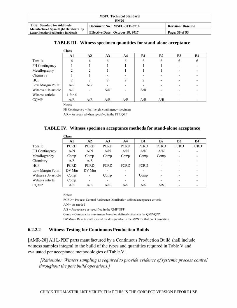
MSFC Technical Standard EM20
Title: Standard for Additively Manufactured Spaceflight Hardware by Laser Powder Bed Fusion in Metals
Document No.: MSFC-STD-3716 Revision: Baseline
Effective Date: October 18, 2017 Page: 39 of 93
CHECK THE MASTER LIST VERIFY THAT THIS IS THE CORRECT VERSION BEFORE USE
TABLE III. Witness specimen quantities for stand-alone acceptance
TABLE IV. Witness specimen acceptance methods for stand-alone acceptance
6.2.2.2 Witness Testing for Continuous Production Builds
[AMR-28] All L-PBF parts manufactured by a Continuous Production Build shall include witness samples integral to the build of the types and quantities required in Table V and evaluated per acceptance methodologies of Table VI.
[Rationale: Witness sampling is required to provide evidence of systemic process control throughout the part build operations.]
ClassA1 A2 A3 A4 B1 B2 B3 B4
Tensile 6 6 6 6 6 6 6 6FH Contingency 1 1 1 1 1 1 - -Metallography 2 2 1 1 1 1 - -Chemistry 1 1 - - - - - -HCF 2 2 2 2 2 - - -Low Margin Point A/R A/R - - - - - -Witness sub-article A/R - A/R - A/R - - -Witness article 1 for 6 - - - - - - -CQMP A/R A/R A/R A/R A/R A/R - -
Notes:
FH Contingency = Full-height contingency specimen
A/R = As required when specified in the PPP/QPP
ClassA1 A2 A3 A4 B1 B2 B3 B4
Tensile PCRD PCRD PCRD PCRD PCRD PCRD PCRD PCRDFH Contingency A/N A/N A/N A/N A/N A/N - -Metallography Comp Comp Comp Comp Comp Comp - -Chemistry A/S A/S - - - - - -HCF PCRD PCRD PCRD PCRD PCRD - - -Low Margin Point DV Min DV Min - - - - - -Witness sub-article Comp - Comp - Comp - - -Witness article Comp - - - - - - -CQMP A/S A/S A/S A/S A/S A/S - -
Notes:
PCRD = Process Control Reference Distribution defined acceptance criteria
A/N = As needed
A/S = Acceptance as-specified in the QMP/QPP
Comp = Comparative assessment based on defined criteria in the QMP/QPP.
DV Min = Results shall exceed the design value in the MPS for that point condition
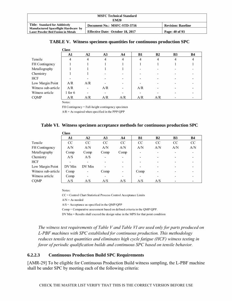
MSFC Technical Standard EM20
Title: Standard for Additively Manufactured Spaceflight Hardware by Laser Powder Bed Fusion in Metals
Document No.: MSFC-STD-3716 Revision: Baseline
Effective Date: October 18, 2017 Page: 40 of 93
CHECK THE MASTER LIST VERIFY THAT THIS IS THE CORRECT VERSION BEFORE USE
TABLE V. Witness specimen quantities for continuous production SPC
Table VI. Witness specimen acceptance methods for continuous production SPC
The witness test requirements of Table V and Table VI are used only for parts produced on L-PBF machines with SPC established for continuous production. This methodology reduces tensile test quantities and eliminates high cycle fatigue (HCF) witness testing in favor of periodic qualification builds and continuous SPC based on tensile behavior.
6.2.2.3 Continuous Production Build SPC Requirements
[AMR-29] To be eligible for Continuous Production Build witness sampling, the L-PBF machine shall be under SPC by meeting each of the following criteria:
ClassA1 A2 A3 A4 B1 B2 B3 B4
Tensile 4 4 4 4 4 4 4 4FH Contingency 1 1 1 1 1 1 1 1Metallography 1 1 1 1 - - - -Chemistry 1 1 - - - - - -HCF - - - - - - - -Low Margin Point A/R A/R - - - - - -Witness sub-article A/R - A/R - A/R - - -Witness article 1 for 6 - - - - - - -CQMP A/R A/R A/R A/R A/R A/R - -
Notes:
FH Contingency = Full-height contingency specimen
A/R = As required when specified in the PPP/QPP
ClassA1 A2 A3 A4 B1 B2 B3 B4
Tensile CC CC CC CC CC CC CC CCFH Contingency A/N A/N A/N A/N A/N A/N A/N A/NMetallography Comp Comp Comp Comp - - - -Chemistry A/S A/S - - - - - -HCF - - - - - - - -Low Margin Point DV Min DV Min - - - - - -Witness sub-article Comp - Comp - Comp - - -Witness article Comp - - - - - - -CQMP A/S A/S A/S A/S A/S A/S - -
Notes:
CC = Control Chart Statistical Process Control Acceptance Limits
A/N = As needed
A/S = Acceptance as-specified in the QMP/QPP
Comp = Comparative assessment based on defined criteria in the QMP/QPP.
DV Min = Results shall exceed the design value in the MPS for that point condition
MSFC Technical Standard EM20
Title: Standard for Additively Manufactured Spaceflight Hardware by Laser Powder Bed Fusion in Metals
Document No.: MSFC-STD-3716 Revision: Baseline
Effective Date: October 18, 2017 Page: 41 of 93
CHECK THE MASTER LIST VERIFY THAT THIS IS THE CORRECT VERSION BEFORE USE
a. Machine maintains an active qualification status per MSFC-SPEC-3717.
b. Machine operates continuously under the same, or equivalent, QMPs.
c. Machine has produced an SPC qualification build per MSFC-SPEC-3717 within 60 days, which was evaluated successfully. (See commentary on SPC qualification build interval.)
d. Machine has produced tensile specimens with results that allow control charts to be established for ultimate strength, yield strength, and elongation, each with a minimum of 30 data points collected over the most recent 10 builds to establish a history of control.
e. Control charts for ultimate strength, yield strength, and elongation, are established according to ASTM E2587, Standard Practice for Use of Control Charts in Statistical Process Control, and maintained within the QMS, with control limits compatible with the applicable PCRD.
f. Builds with tensile results violating control chart acceptance criteria are assigned a non-conformance in the QMS that initiates an evaluation of the part and the L-PBF machine’s process history.
g. Corrective actions are taken for any control chart non-conformance that cannot be uniquely isolated to the non-conforming build.
h. The machine is given an inactive qualification status until the conclusion of the evaluation, any necessary corrective actions are complete, and the CEO concurs with the resolution.
i. Documentation closing the non-conformance recommends either returning the machine to active qualification or re-qualifying the machine based on the nature of the non-conformance and necessary corrective actions.
[Rationale: The reduced witness sampling in Continuous Build operations depends upon a rigorously defined, steady-state production environment that is monitored and controlled to provide rationale for part quality and reliability. These SPC requirements provide for that SPC environment.]
Alternatives to the default 60-day SPC qualification build interval may be proposed, with justification, in the AMCP to suit the production environment. Alternative intervals may be set on number of builds, machine hours, or other quantifiable metrics that provide monitoring at a comparable interval.
Once statistical control is established on an L-PBF machine, evaluation of process capability according to ASTM E2281, Standard Practice for Process Capability and Performance Measurement, is recommended.
6.2.2.4 Use of PCRD in Witness Test Acceptance
MSFC Technical Standard EM20
Title: Standard for Additively Manufactured Spaceflight Hardware by Laser Powder Bed Fusion in Metals
Document No.: MSFC-STD-3716 Revision: Baseline
Effective Date: October 18, 2017 Page: 42 of 93
CHECK THE MASTER LIST VERIFY THAT THIS IS THE CORRECT VERSION BEFORE USE
The PCRD, described in section 5.4.5 and Appendix C, yields a set of acceptance criteria defined by the CEO to identify witness test results that are not representative of past performance while balancing the need to prevent false negative calls. Appendix C contains an example of the development of a tensile strength PCRD and acceptance criteria. The witness test results are evaluated against the PCRD acceptance criteria in a manner similar to other quality assurance metrics. Acceptance criteria should not be complicated to interpret.
The PCRD for HCF required for witness testing of stand-alone builds is a fit to the typical fatigue life of the witness HCF specimen tested under consistent environment and cyclic stress conditions. A recommended HCF acceptance criterion is the average measured fatigue life of the witness specimens exceeds the lower 95% probability limit of the fatigue PCRD.
6.2.3 Production Engineering Record
[AMR-30] The L-PBF part production process shall be governed by a comprehensive production engineering record to sequence and document the execution of all steps needed to produce the final part.
[Rationale: L-PBF parts cannot be reliably produced under a QMS unless there is a production engineering record to control and sequence operations and inspection points.]
The production engineering record is also commonly called a shop traveler, manufacturing router, production planning, or engineering master.
The production engineering record implements the QPP (see Section 6.2.6), controlling all aspects of the L-PBF production process. The production engineering record is integral with the QMS. The requirement for production engineering records extends to vendors involved in L-PBF production.
As a quality record, the production engineering record may also be used as the documentation source of process control information and, depending upon its implementation, a record of verifications made during the process. The production engineering record may reference other checklists or operating instructions that are actively maintained as part of the quality management system.
NASA may review any production engineering record at its discretion.
6.2.4 Pre-production Article Requirements
[AMR-31] A pre-production article evaluation verifying quality of part and material shall be conducted for all L-PBF parts, with the plan for evaluation being approved as part of the PPP.
MSFC Technical Standard EM20
Title: Standard for Additively Manufactured Spaceflight Hardware by Laser Powder Bed Fusion in Metals
Document No.: MSFC-STD-3716 Revision: Baseline
Effective Date: October 18, 2017 Page: 43 of 93
CHECK THE MASTER LIST VERIFY THAT THIS IS THE CORRECT VERSION BEFORE USE
[Rationale: A pre-production article evaluation is necessary to confirm that the design intent of the part is fully realized by the defined part process. Many aspects of part quality will vary with part process and can only be verified through the pre-production article assessment such as material internal quality and mechanical performance.]
See commentary for Section 6.2.4 in Appendix B regarding the terms “pre-production article” and “first article.”
To meet the intent of this requirement, the pre-production article evaluation is based upon the finalized build configuration, including all parts, supports, and witness specimens, and includes all part processes beginning with L-PBF through final part inspection, acceptance, and marking. If multiple parts are built simultaneously during a build, a representative subset of the parts may be used for the pre-production article evaluation. The pre-production article evaluation plan, given in the PPP or referenced therein as a separate plan, includes a complete description of each stage of the evaluation, with emphasis on evaluations needed as the part proceeds through processing. Some pre-production article evaluations may require more than one part to adequately capture all objectives. The pre-production article evaluation plan, process, and report should follow the intent of SAE AS9102, Aerospace First Article Inspection Requirement, except that as a pre-production article (as opposed to “first article”), the evaluations extend beyond the production engineering requirements to matters of material internal quality and mechanical performance. The pre-production article evaluation plan is approval as part of the PPP.
At a minimum, the pre-production article evaluation plan should address the following topics, though relevance and importance are expected to vary by part:
Powder removal and confirmation techniques.
Platform removal procedures.
Thermal processing procedures.
Dimensional inspections, accessible and post-sectioning.
Surface improvement procedures, sufficiency and coverage.
Surface texture measurements, accessible and post-sectioning.
Part sectioning cut plans.
Testing within part: metallography, chemistry, mechanical (QMP to be confirmed).
AM risk area evaluations - Sectioning and tests target any high AM risk areas of the part.
MSFC Technical Standard EM20
Title: Standard for Additively Manufactured Spaceflight Hardware by Laser Powder Bed Fusion in Metals
Document No.: MSFC-STD-3716 Revision: Baseline
Effective Date: October 18, 2017 Page: 44 of 93
CHECK THE MASTER LIST VERIFY THAT THIS IS THE CORRECT VERSION BEFORE USE
Witness specimen evaluation - All defined witness specimens for the build are tested and reported.
Part cleaning requirements.
See further commentary for section 6.2.2 in Appendix B.
6.2.5 Additive Manufacturing Readiness Review
[AMR-32] An AMRR shall be conducted for all L-PBF parts in accordance with the AMRR definition of Section 3.2.
[Rationale: The AMRR process is required to confirm that the requirements of the production engineering record are complete and will render a part meeting the requirements of the certified design. The multi-disciplinary AMRR process provides record of authorization to proceed to production with a QPP.]
For the AMRR process, all constituents of a candidate part process are assembled for review, including the candidate production engineering record, part drawing, approved PPP, successful pre-production article report, and any additional documentation influential to the part production process.
If the AMRR team is not satisfied with the candidate part process, the AMRR team clearly identifies all deficiencies. Once deficiencies are corrected, the candidate part process is subject to another AMRR.
At the successful conclusion of the AMRR, the approved candidate part process is established as a QPP per Section 6.2.6.
6.2.6 Qualified Part Process, Establishment
[AMR-33] Following a successful AMRR, the QPP shall be established within the QMS with no changes to the build configuration, its electronic files, or post-build processes permitted without the written approval of the CEO.
The establishment of a QPP is the technical authorization to proceed with part production.
At the discretion of NASA, written approval from NASA for any changes to a QPP may also be required.
[Rationale: Establishing the QPP formally defines and locks the process for part production in the QMS. The quality and consistency of L-PBF parts cannot be assured without establishing a QPP.]
This requirement intends that the content of the build plate cannot be altered relative to that used in the pre-production article qualification process—no parts, supports, or specimens are added, subtracted, rearranged, or altered in the build.
MSFC Technical Standard EM20
Title: Standard for Additively Manufactured Spaceflight Hardware by Laser Powder Bed Fusion in Metals
Document No.: MSFC-STD-3716 Revision: Baseline
Effective Date: October 18, 2017 Page: 45 of 93
CHECK THE MASTER LIST VERIFY THAT THIS IS THE CORRECT VERSION BEFORE USE
6.2.7 Qualified Part Process, Modifications
[AMR-34] The CEO shall define in the AMCP the methodology for re-qualification of the part production process when changes to a QPP are required, including when the AMRR process is used to re-establish the QPP following any modifications.
[Rationale: It is acknowledged that occasionally circumstances arise where changes to the locked process are necessary. Defining in the AMCP the methodology for re-qualifying the part production process following a change ensures rigorous, proportionate, and consistent re-qualification procedures are followed.]
Incremental or partial re-qualification schemes are allowed for minor changes. Changes that impact the part geometry, support structures, or that may otherwise impact the part build process are expected to repeat the pre-production article process. The AMRR process is intended to be used to re-establish the QPP following any modifications.
Allowing additional L-PBF machines (QMPs) to produce parts under the QPP is a common modification; therefore, the following criteria may be included in the AMCP as a pre-approved method for a QPP change for additional QMPs.
Additional QMPs may be added to a QPP under the following scenario:
a. The addition of the new QMP is the only change to the QPP.
b. The new QMP is to be used by the same L-PBF process vendor and facility for which the QPP was established.
c. The new QMP is nominally similar to the baseline QMP.
d. The new QMP is properly registered to the MPS for the part.
e. The new QMP has documentation of a successful pre-production article evaluation of the part.
See commentary for Section 6.2.7 in Appendix B.
6.2.8 Control of the Digital Product Definition
[AMR-35] All electronic files and associated parameters used to establish the digital product definition (DPD) of the complete build assembly as finalized by the QPP shall be documented as part of the QPP, archived, and maintained fully traceable, including the use of the cryptographic hash (CH) for unambiguous identification of files.
[Rationale: The L-PBF process includes a significant number of electronic files and manipulations to get from design to part. The full integrity of the design state can only be maintained if the complete chain of electronic identity is defined and properly archived.]
MSFC Technical Standard EM20
Title: Standard for Additively Manufactured Spaceflight Hardware by Laser Powder Bed Fusion in Metals
Document No.: MSFC-STD-3716 Revision: Baseline
Effective Date: October 18, 2017 Page: 46 of 93
CHECK THE MASTER LIST VERIFY THAT THIS IS THE CORRECT VERSION BEFORE USE
For this requirement, the DPD includes any electronic data source or record that would be needed to fully reproduce the build as it was defined at the time the part process was qualified as a QPP, including any manually set parameters in software used to process the part from computer-aided design (CAD) to the final, assembled build file, which includes support structures, witness specimens, and any other content in the build.
Each file necessary to create the build is identified by filename and its cryptographic hash as part of the QPP definition. To maintain traceability, electronic data is archived with necessary safeguards against loss as required by the QMS.
Electronic data that contains information considered proprietary or controlled under regulations such as the International Traffic in Arms Regulations should be marked and controlled according to regulation. Note that these rules require appropriate access control to data marked with such restrictions at all stages of producing L-PBF parts.
See further commentary for section 6.2.8 in Appendix B.
6.2.8.1 Part Model Integrity
[AMR-36] A methodology for verifying the integrity of part models throughout all stages of the digital part definition associated with the L-PBF process shall be documented and enforced through the AMCP.
[Rationale: To ensure the certified design intent is reflected in the part, the integrity of the part design must be verified at the original CAD, then maintained throughout the process of geometry conversion to render a complete build file for the L-PBF part.]
Just as standard processes exist to confirm part drawings properly specify final part configuration prior to release, a similar process is required to check the integrity of solid models and any associated information containing design intent. Design integrity must be maintained throughout the AM-related manipulations of the post-design electronic data such as error-free creation of stereolithography (STL) files with proper resolution, and generation of L-PBF platform-specific slice files.
6.2.9 Build Execution
[AMR-37] The production engineering record for the QPP shall contain steps verifiable through the QMS that ensure all procedures and checklists governing set up and initiation of builds are followed.
[Rationale: Reliable part production can only occur with properly controlled production planning. A version of the production engineering record is integral to the use of a QMS governing production.]

MSFC Technical Standard EM20
Title: Standard for Additively Manufactured Spaceflight Hardware by Laser Powder Bed Fusion in Metals
Document No.: MSFC-STD-3716 Revision: Baseline
Effective Date: October 18, 2017 Page: 47 of 93
CHECK THE MASTER LIST VERIFY THAT THIS IS THE CORRECT VERSION BEFORE USE
6.2.10 Planned Build Interruptions
[AMR-38] Any planned interruption of the L-PBF build shall be documented in the QPP with allowable build height range(s) for the interruption and all planned post-build evaluations of the process restart interface.
[Rationale: Build interruptions that are known to be required, such as for powder refilling, are planned to allow confirmation of the interruption in the pre-production article and to emphasize inspections and witness sample evaluations at the interruption.]
Every effort should be made to eliminate build interruptions.
Planned build interruptions are allowed only if qualified procedures exist and are followed. The QMP defines the limitations for a planned interruption and qualifies the procedures for handling the interruption and restoration of the build process.
6.2.11 Unplanned Build Interruptions
[AMR-39] Any unplanned build interruption, including planned interruptions occurring outside their defined build height ranges, shall be recorded as a non-conformance in the QMS.
[Rationale: Unplanned interruptions in the L-PBF process are a sign of a deviation in the steady-state process, often resulting from an imperfection in the build or a fault in the machine and, therefore, are prone to the creation of defects within parts. Documentation as a non-conformance ensures all unplanned interruptions are evaluated for the potential for part defects.]
Every effort should be made to eliminate build interruptions.
Unplanned build interruptions may be restarted only if qualified procedures exist and are followed. The QMP defines the limitations for a planned interruption and qualifies the procedures for handling the interruption and restoration of the build process.
6.2.12 Post-build Operations
Through the production engineering records, the QPP should address all controls and sequencing of the post-build operations. At a minimum, the post-build operations described in sections 6.2.12.1 through 6.2.12.8 are required to be addressed.
6.2.12.1 Powder Removal
[AMR-40] The production engineering records shall provide specific procedures for removing powder for any part with geometry precluding line-of-sight confirmation of powder removal, including methods to confirm powder removal prior to further part processing.
MSFC Technical Standard EM20
Title: Standard for Additively Manufactured Spaceflight Hardware by Laser Powder Bed Fusion in Metals
Document No.: MSFC-STD-3716 Revision: Baseline
Effective Date: October 18, 2017 Page: 48 of 93
CHECK THE MASTER LIST VERIFY THAT THIS IS THE CORRECT VERSION BEFORE USE
[Rationale: Powder remaining in the part presents hazards to proper part and system operations.]
Removing residual powder following the hot isostatic pressing (HIP) process may not be feasible; therefore, it is important that all passages are verified clear of powder prior to this step. Proper cleanliness may be impossible to achieve later in post processing, particularly for debris-sensitive hardware.
6.2.12.2 As-Built Part Inspections
[AMR-41] Immediately upon build completion and removal from the powder bed, all parts shall receive, at minimum, full visual inspection for any indications of build anomalies prior to processes that may alter the as-built state of the part, such as bead or grit blasting, with all anomalies recorded in detail in the QMS.
[Rationale: Many indicators of L-PBF process quality are best evaluated prior to further part processing, including many indicators, such as coloration or support damage, that may be eliminated during further part processing.]
Build anomalies include, but are not limited to, witness lines on the part surface (see definition), unusual discoloration, laminar defects such as cracks or tears, separation of part from support structures, and geometric distortion.
At this time, the L-PBF machine should receive an inspection for any anomalies. Any damage or nicks in the edge of the recoater blade should be noted.
High quality photographs to document the as-built part inspection process is recommended, particularly unusual observations or anomalies.
6.2.12.3 Support Structure Removal
[AMR-42] The production engineering record shall provide the sequence of support structure removal from the part relative to other post-build operations and controls the method of support structure removal.
[Rationale: The process for support structure removal needs to be controlled to prevent part damage and to ensure interfacing part surfaces retain their intended quality.]
6.2.12.4 Platform Removal
[AMR-43] The production engineering record shall provide the sequence of part removal from the build platform relative to other post-build operations and control the method of platform removal.
[Rationale: Removal of the part from the build platform is a significant operation having potential consequences for part integrity; therefore, it is a controlled process.]
MSFC Technical Standard EM20
Title: Standard for Additively Manufactured Spaceflight Hardware by Laser Powder Bed Fusion in Metals
Document No.: MSFC-STD-3716 Revision: Baseline
Effective Date: October 18, 2017 Page: 49 of 93
CHECK THE MASTER LIST VERIFY THAT THIS IS THE CORRECT VERSION BEFORE USE
Considerations in sequencing platform removal include dimensional control of the part and stress relief operations, powder removal considerations, effect of the mass of the build platform in heat treating operations, etc.
6.2.12.5 Machining
[AMR-44] The production engineering record shall provide specific sequences for all machining operations needed to achieve the final part geometry.
[Rationale: Machining operations need to be properly staged relative to joining operations, inspections, and thermal processing to ensure part integrity is maintained and verifiable.]
6.2.12.6 Part Serialization
[AMR-45] All L-PBF parts shall be serialized.
[Rationale: The L-PBF process is considered a “process control sensitive” such that each instance of the process has the likelihood of uniqueness; therefore, traceability by part back to that process is essential to managing part and inventory risk.]
6.2.12.7 Part Marking
[AMR-46] The production engineering record shall provide specifications for marking parts with part identifiers and serial numbers, including the location and method for all marking.
[Rationale: Uncontrolled marking procedures present unwarranted risk to the part.]
Incorporation of a static part identifier directly in the build geometry is acceptable as long as it is protected during post-build operations and does not interfere with part acceptance inspections. The use of the build process to implement serialization is not compatible with a locked QPP.
6.2.12.8 Part Packaging
[AMR-47] The production engineering record shall provide controls and instructions for proper handling and packaging of the part, including any customized protective containers.
[Rationale: Part integrity can only be maintained when proper handling and packaging controls are in place to preclude damage.]
6.2.13 Post-build Operations Requiring Specific Controls
The post-build operations in this section will generally require specific process control.
MSFC Technical Standard EM20
Title: Standard for Additively Manufactured Spaceflight Hardware by Laser Powder Bed Fusion in Metals
Document No.: MSFC-STD-3716 Revision: Baseline
Effective Date: October 18, 2017 Page: 50 of 93
CHECK THE MASTER LIST VERIFY THAT THIS IS THE CORRECT VERSION BEFORE USE
6.2.13.1 Surface Treatments
[AMR-48] Any surface treatment operation applied to the part that is influential to the performance of the part, structural or otherwise, shall be under specific process control, meaning the process is fully developed, demonstrated, clearly specified, and qualified, with the locked surface treatment process being part of, or referenced by, the production engineering records.
[Rationale: Surface treatment operations may have significant impact on part performance and may underlie assumptions of material capability such as fatigue performance; therefore, improperly controlled surface treatments can adversely affect part quality and safety.]
See commentary for section 6.2.13.1 in Appendix B.
6.2.13.2 Cleaning
[AMR-49] Part cleaning procedures and the associated cleanliness requirements shall be specified in the QPP and implemented through the production engineering records.
[Rationale: Failure to properly control cleaning procedures can lead to contamination-related failures within the part or system. Cleaning requirements are required by the contamination control plan for the hardware.]
Cleanliness levels and methods of verification are governed by the contamination control plan for the hardware and comply with appropriate standards such as IEST-STD-CC1246, Product Cleanliness Levels - Application, Requirements, and Determination, or MSFC-SPEC-164, Cleanliness of Components for Use in Oxygen, Fuel, and Pneumatic Systems, Specification for.
See further commentary for Section 6.2.13.2 in Appendix B.
6.2.13.3 Rationale for Oxygen Cleanliness
[AMR-50] L-PBF parts used in oxygen service shall have specific rationale in the PPP addressing required cleanliness for particulate and hydrocarbon residue.
[Rationale: L-PBF parts present clear hazards to oxygen systems due to the potential for particle liberation or trapping hydrocarbon contaminants. This requirement ensures the Oxygen Compatibility Assessment required by NASA-STD-6016 acknowledges the potentially unique hazards of the L-PBF product form.]
See commentary for Section 6.2.13.3 in Appendix B.
MSFC Technical Standard EM20
Title: Standard for Additively Manufactured Spaceflight Hardware by Laser Powder Bed Fusion in Metals
Document No.: MSFC-STD-3716 Revision: Baseline
Effective Date: October 18, 2017 Page: 51 of 93
CHECK THE MASTER LIST VERIFY THAT THIS IS THE CORRECT VERSION BEFORE USE
6.2.13.4 Welding
[AMR-51] All welds on L-PBF parts shall be developed and qualified to an appropriate aerospace welding specification as approved by the CEO.
[Rationale: Welding operations on L-PBF parts are not exempted from standard weld process controls as implemented through NASA-STD-6016. Unique preparation and sequencing may be involved in welding of L-PBF parts.]
Welding operations are sequenced by the production engineering record to accommodate machining to remove remnants of as-built L-PBF surface from weld lands and to stage heat treatment operations to optimize weld performance and minimize weld residual stress.
This MSFC Technical Standard does not levy specific inspection requirements for welds in L-PBF hardware. Inspections are dictated by standard practice based on the class of weld or the fracture control classification of the weld.
Welding standards will typically be levied by the program or project through materials and processes requirements (NASA-STD-6016) and tailored by the CEO.
6.2.13.5 Thermal Processing
[AMR-52] The production planning record shall ensure the part is subject to all thermal processing steps as defined in the applicable QMP.
[Rationale: Part performance is assumed to follow properties developed with microstructures evolved through thermal processes defined in the QMP (See MSFC-SPEC-3717); therefore, without proper thermal processing, part materials may not perform as intended.]
6.2.14 Part Inspection and Acceptance
This section provides controls for part repair and the minimum requirements for part inspection and acceptance. Note that the witness testing and acceptance requirements of Section 6.2.2 are a fundamental aspect of the part acceptance process.
6.2.14.1 Repair Allowances and Procedures
[AMR-53] The QPP shall include explicit provisions controlling any operation used to repair or improve the condition of the L-PBF part due to defect in accordance with the following:
a. NASA may require prior approval be obtained for any or all repairs;
b. Repair operations are not allowed without prior written authorization from the CEO;
c. All repair operations require full documentation as a non-conformance record in the QMS and repair records become part of the certificate of compliance for the part;
MSFC Technical Standard EM20
Title: Standard for Additively Manufactured Spaceflight Hardware by Laser Powder Bed Fusion in Metals
Document No.: MSFC-STD-3716 Revision: Baseline
Effective Date: October 18, 2017 Page: 52 of 93
CHECK THE MASTER LIST VERIFY THAT THIS IS THE CORRECT VERSION BEFORE USE
d. Part operations that constitute a repair include, but are not limited to, blending, sanding, grinding, machining, welding, or brazing for the purposes of defect removal.
[Rationale: Uncontrolled or undocumented repair is not allowed for two reasons: first, such repairs are a danger to the integrity of the part; and second, such repairs obfuscate process escapes and hinder the development and implementation of corrective actions.]
6.2.14.2 Non-Destructive Evaluation
[AMR-54] All L-PBF parts shall receive comprehensive NDE for surface and volumetric defects within the limitations of technique and part geometry unless otherwise substantiated as part of the Integrated Structural Integrity Rationale per section 6.1.4.
[Rationale: NDE provides a necessary degree of quality assurance for L-PBF parts in addition to the process controls of this MSFC Technical Standard. There is currently no methodology to preclude all L-PBF process failure modes through the available process controls.]
Standards with NDE acceptance criteria for welding or casting quality are not considered applicable to L-PBF hardware.
See commentary for section 6.2.14.2 in Appendix B.
6.2.14.3 Non-Destructive Evaluation, Non-Conformance Items
Non-conformance findings related to NDE are handled through the QMS similar to other scenarios; however, for Class A parts, NDE indications of cracks, crack-like defects, or other findings of undetermined source should be elevated to senior review and disposition, as required by applicable fracture control policy.
Each project and CEO will have defined rules for resolution of non-conformance items, including which are elevated for higher-level review and risk visibility. Senior review of crack-like defects is important not only for the integrity of the non-conforming part, but also regarding understanding the process escape that created the condition. The common forum for senior non-conformance review in the NASA system is the Material Review Board (MRB). For fracture critical L-PBF parts, the RFCB should be made aware of non-conformances in flight hardware involving defects.
6.2.14.4 Non-Destructive Evaluation, In-situ Process Monitoring
[AMR-55] Prior to use as a quantitative contributor to L-PBF part Integrated Structural Integrity Rationale, passive in-situ process monitoring technologies shall be qualified by the CEO to the satisfaction of NASA in a manner analogous to other NDE techniques.
MSFC Technical Standard EM20
Title: Standard for Additively Manufactured Spaceflight Hardware by Laser Powder Bed Fusion in Metals
Document No.: MSFC-STD-3716 Revision: Baseline
Effective Date: October 18, 2017 Page: 53 of 93
CHECK THE MASTER LIST VERIFY THAT THIS IS THE CORRECT VERSION BEFORE USE
[Rationale: All processes that are used to establish quantifiable quality assurance metrics are qualified to verify detection reliability, calibration, and implementation against established criteria. If in-situ monitoring techniques are employed for such purposes, though new, the need for such qualification is unchanged.]
Active in-situ monitoring technologies that alter the defined L-PBF process in response to monitored phenomena are not currently acceptable per this MSFC Technical Standard.
Certification of a passive in-situ process monitoring technology relies upon a thorough understanding of the physical basis for the measured phenomena, a proven causal correlation of the measured phenomena to a well-defined defective process state, and a proven level of reliability for detection of the defective process state.
6.2.14.5 Proof Testing
[AMR-56] All L-PBF parts shall be proof tested as part of acceptance testing, unless otherwise substantiated as part of the Integrated Structural Integrity Rationale per section 6.1.4.
[Rationale: Proof testing provides evidence of structural integrity and may be a significant contributor to the structural integrity rationale. Structural failure risks due to defects, uncontrolled processes, or errant workmanship are mitigated though the proof test acceptance test.]
It is highly recommended that all L-PBF parts are proof tested as effectively as their design will accommodate. For fracture critical/damage tolerant parts, the integrity proof test assessment may also require an evaluation of the flaw size screened in proof and the estimated life assured by proof testing. Proof test cyclic life evaluations may occur analytically or experimentally.
See commentary for section 6.2.14.5 in Appendix B.
6.2.14.6 Dimensional Inspections
[AMR-57] The production engineering record shall be explicit regarding all physical measurements and associated acceptance criteria required for part acceptance, including dimensional inspections and surface texture measurements.
[Rationale: Confirmation of physical measurements is necessary for part conformance but is also an aspect of L-PBF process control. Dimensional errors for the L-PBF process are an indication of process escape.]
Internal measurements may be confirmed utilizing computed tomography provided a part analog reference is used to confirm accuracy and precision of the measurements as well as the calibration of the tool and data post-processing methods.
MSFC Technical Standard EM20
Title: Standard for Additively Manufactured Spaceflight Hardware by Laser Powder Bed Fusion in Metals
Document No.: MSFC-STD-3716 Revision: Baseline
Effective Date: October 18, 2017 Page: 54 of 93
CHECK THE MASTER LIST VERIFY THAT THIS IS THE CORRECT VERSION BEFORE USE
6.2.14.7 Certification of Compliance Records
[AMR-58] The production engineering record shall contain a list of all records needed to establish part compliance with the requirements of the QPP, with all such records maintained within the QMS.
[Rationale: For proper L-PBF part traceability, it is important that the production engineering record unambiguously define what records are required to establish the complete production data package for the part. Without such accounting, data packages for parts may go incomplete, resulting in parts with insufficient quality rationale.]
In accordance with NRRS 1441.1, NASA Records Retention Schedules, contract and QMS requirements, all part records are archived for the prescribed period and remain fully traceable, including those provided by external vendors for operations such as heat treating, machining, or inspection. All witness specimen test results and records as well as non-conformance documentation are included in the certification of compliance records for the part. When complete, it is recommended that a final, summarized certification of conformance record be generated demonstrating all requirements have been met, all non-conformances resolved, and that the part is fit for service.
7. Establishing L-PBF Material Property Design Values
This section provides requirements and guidance related to the methodology of establishing design values for L-PBF materials accounting for unique aspects of the product form. To meet the intent of these requirements, the material testing for physical or mechanical properties is based upon applicable testing standards (for example, ASTM E8/E8M for tensile testing, ASTM E466, Standard Practice for Conducting Force Controlled Constant Amplitude Axial Fatigue Tests of Metallic Materials, for fatigue testing, or ASTM E1820, Standard Test Method for Measurement of Fracture Toughness, for fracture toughness testing); and the tests are executed by a test laboratory accredited through Nadcap™, or the American Association of Laboratory Accreditation (A2LA), other nationally accepted accreditation body, or by direct approval of the CEO.
7.1 Physical and Constitutive Properties
Physical and constitutive properties are presented as typical basis (mean value) and are defined as a function of temperature. These values are generated as described by the MMPDS. Because they are typical basis, these values may be considered Lot-Mature with three (3) powder lots and five (5) build/heat treat lots.
See further commentary for Section 7.1 in Appendix B.
7.2 Tensile Properties
MSFC Technical Standard EM20
Title: Standard for Additively Manufactured Spaceflight Hardware by Laser Powder Bed Fusion in Metals
Document No.: MSFC-STD-3716 Revision: Baseline
Effective Date: October 18, 2017 Page: 55 of 93
CHECK THE MASTER LIST VERIFY THAT THIS IS THE CORRECT VERSION BEFORE USE
[AMR-59] Statistical assessment of L-PBF material properties to derive design values for ultimate strength, yield strength, and elongation shall be governed the following:
a. Design values are bounded by the 99% probability at 95% confidence one-sided tolerance limit estimated for the population.
b. Lot variability requirements are defined by Section 5.4.2.1.
c. A minimum of 100 degrees of freedom (specimens and lots) are required to initially establish design values.
d. Design values supported by fewer than 300 degrees of freedom utilize a Design Value Margin greater than or equal to the estimated coefficient of variation (CV) of the available data; thus, Design Value ≤ (99/95 one-sided tolerance limit) * (1 - CV). See Figure 5, Substantiation of design value from MPS data, in Appendix C.
e. The tensile property database is maintained by the CEO and updated on a periodic basis as additional data become available from process control-related activities, including witness sampling, pre-production article evaluations, QMP development, and machine qualification.
f. Test and data analysis methodologies, except as noted in this requirement, following the intent of the MMPDS guidelines for static tensile property development.
[Rationale: These criteria partially adapt the MMPDS requirements for design values to meet the unique, process-sensitive scenario of L-PBF materials.]
When established design values decrease, the programmatic costs are significant. It is strongly recommended that initial design values incorporate a Design Value Margin sufficient to guard against such a decrease as the supporting data population of the MPS grows and periodic reassessments of design values occur. As L-PBF processes and the database mature, the design values may be allowed to increase by reducing the Design Value Margin, if the data support.
The intent of the A-basis static strength property requirements of NASA-STD-6016 are satisfied when all material characterizations and process controls of this MSFC Technical Standard are fully implemented. The submittal of an MUA describing the substantiation of the MPS satisfies the NASA-STD-6016 material property control requirements. This MPS documentation also satisfies material property requirements levied by other structural requirements documents such as NASA-STD-5012 or JSC 65828.
7.2.1 Ratio-Derived Properties
The paired ratio method may be used to populate the MPS with other flow-dominated material properties, as required. In this context, flow-dominated properties are quasi-static and governed by the onset of plastic flow and subsequent ductile failure mechanisms.
MSFC Technical Standard EM20
Title: Standard for Additively Manufactured Spaceflight Hardware by Laser Powder Bed Fusion in Metals
Document No.: MSFC-STD-3716 Revision: Baseline
Effective Date: October 18, 2017 Page: 56 of 93
CHECK THE MASTER LIST VERIFY THAT THIS IS THE CORRECT VERSION BEFORE USE
It is reasonably assumed that these properties will follow the trends of tensile properties in magnitude and variability.
[AMR-60] To implement the matched pair methodology for MPS properties, a minimum of ten tests shall be conducted to establish the matched pair ratio for a derived property with the specimens used to create a matched pair taken from the same build/heat treat lot.
[Rationale: This requirement is intended to meet the intent of the MMPDS methodology on derived properties by ratio testing as adapted for L-PBF.]
Properties developed with the paired ratio methodology are subject to the lot requirements in section 5.4.2.1 of the main body.
The most common properties derived by the ratio method are compression yield, shear ultimate, and bearing strength. When developed with the ratio method, these properties are often referred to as “derived properties.” The method to derive properties with matched pair ratios using tensile strengths is described in the MMPDS.
7.3 Fatigue
[AMR-61] As required for structural assessment, or at customer discretion, the MPS for any given L-PBF product shall include fatigue properties developed in accordance with the following policies:
a. The process for developing design fatigue curves from the test data is described as part of the MUA substantiating the MPS methodology per section 5.4 of the main body;
b. Fatigue initiation life properties are developed in the form of stress-life or strain-life curves;
c. All fatigue design curves are labeled with their basis, e.g., typical or bounding;
d. Fatigue properties are subject to the lot requirements of section 5.4.2.1 of the main body;
e. Ten or more tests are used to define a fatigue curve for a given condition and, for HCF, a minimum of four tests are within 10% of the stress defined as the fatigue limit; (See the definition of fatigue limit for this MSFC Technical Standard.)
f. If the MPS fatigue design curves are applied to Class A parts with cycle counts ≥108, fatigue test data are acquired to substantiate the design curve in this regime, except for Class B parts, where an analytical methodology for predicting such fatigue limits may be employed when properly documented;
g. Effects of surface textures rendered by the L-PBF process, and surface improvement treatments, are included in the fatigue design curves of the MPS as follows:
MSFC Technical Standard EM20
Title: Standard for Additively Manufactured Spaceflight Hardware by Laser Powder Bed Fusion in Metals
Document No.: MSFC-STD-3716 Revision: Baseline
Effective Date: October 18, 2017 Page: 57 of 93
CHECK THE MASTER LIST VERIFY THAT THIS IS THE CORRECT VERSION BEFORE USE
i. Surface improvement methods such as honing or polishing that do not ensure complete, uniform removal of all as-built surface remnant or at least 0.38 mm (0.015 in) from all treated surfaces are evaluated through fatigue testing;
ii. Fatigue life of fully machined surfaces may use standard surface finish factors applied to the neutral-surface fatigue curves;
iii. Surface treatments such as peening that improve fatigue life by altering the near-surface stress state without actually removing the surface are characterized through fatigue testing;
iv. Surface treatments used to improve fatigue capability are controlled by a process specification and are placed under process control. Application of such processes to parts is addressed in the PPP and evaluated in the pre-production article.
[Rationale: Fatigue properties are critical to L-PBF part integrity. There are currently no other sources providing these characterization requirements.]
Because fatigue capability can be strongly influenced by the L-PBF process, in certain cases the customer may require fatigue property characterization over and above those invoked by structural assessment requirements. For example, if a structure does not require fatigue initiation life assessment because a damage tolerance assessment exists, the need to understand initiation capability may remain important to the overall reliability of the structure throughout its life.
It is important that the fatigue curve basis be consistent with the analytical methodology prescribed by governing structural requirements.
See further commentary on Section 7.3 in Appendix B.
7.4 Fracture Mechanics
[AMR-62] When design assessment includes evaluation of crack-like defects by fracture mechanics, fracture toughness and fatigue crack growth rate properties characterized from L-PBF material shall be included in the MPS.
[Rationale: Fracture mechanics properties vary with alloy product form; therefore, characterization of these properties is required in the L-PBF product form.]
See commentary on Section 7.4 in Appendix B.
7.5 Stress Rupture and Creep Deformation
[AMR-63] When required for part assessment, material properties for stress rupture or creep mechanisms shall be included in the MPS.
[Rationale: Stress rupture and creep properties vary with alloy product form; therefore, characterization of these properties is required in the L-PBF product form.]
MSFC Technical Standard EM20
Title: Standard for Additively Manufactured Spaceflight Hardware by Laser Powder Bed Fusion in Metals
Document No.: MSFC-STD-3716 Revision: Baseline
Effective Date: October 18, 2017 Page: 58 of 93
CHECK THE MASTER LIST VERIFY THAT THIS IS THE CORRECT VERSION BEFORE USE
The MMPDS provides guidance for performing these tests as well as for data reduction and presentation. Designs requiring dependable stress rupture or creep performance should include a stress rupture witness test in the QPP. This is consistent with common practice for lot release control for many high temperature alloy products.
7.6 Temperature and Environmental Effects
[AMR-64] When required for part assessment, the MPS shall include the effect of temperature on material properties based on testing of the L-PBF product form.
[Rationale: Temperature and environmental effects vary with alloy product form; therefore, characterization of these effects on properties is required in the L-PBF product form.]
The temperature effects on material properties in the MPS are evaluated by the methods shown in the MMPDS, which allow for flexibility in determining temperature effects working curves.
7.7 Welds
[AMR-65] Material properties for welds in L-PBF products shall be developed using the L-PBF product form and incorporated into the applicable MPS, with Lot-Maturity requirements to substantiate the statistical basis of weld material properties documented and approved as part of the MUA substantiating the MPS methodology per Section 5.4.
[Rationale: Weld properties vary with alloy product form; therefore, characterization of these weld properties is required in the L-PBF product form.]
MSFC Technical Standard EM20
Title: Standard for Additively Manufactured Spaceflight Hardware by Laser Powder Bed Fusion in Metals
Document No.: MSFC-STD-3716 Revision: Baseline
Effective Date: October 18, 2017 Page: 59 of 93
CHECK THE MASTER LIST VERIFY THAT THIS IS THE CORRECT VERSION BEFORE USE
APPENDIX A. PART PRODUCTION PLAN CONTENT
This Appendix is not a mandatory part of the standard. The information contained herein is intended for guidance only.
The L-PBF PPP is expected to address the following content. Items in this list that are fully controlled by the AMCP need not be repeated in the PPP. The combined requirements of the AMCP, part drawing, and PPP are to be sufficient to produce the production engineering record.
Drawing number and part name Part synopsis, providing a brief summary of
o The purpose of the part in context to the system, o The operational environments (temperatures, fluids), o CAD model views to illustrate the part and key features
Material o Identification of the QMP specified for production. o Identification of MPS used for assessment
Part classification with summary rationale for consequence of failure, structural demand, and AM risk
Integrated Structural Integrity Rationale for the part o Describe limiting factors in strength and fracture analyses o Highlight areas of high structural demand and high AM risk per classification o Describe all non-destructive testing and the degree of coverage or any limitations o Describe all proof test operations, including role in integrity rationale, method of
analysis, and coverage or limitations List of required witness tests, witness articles, and associated acceptance
requirements Illustration of the complete build with part orientation, location, and witness
specimens Summary list or table with all production steps in sequence as governed by the
Production Engineering Record o Include all key operations such as build, powder removal, as-built inspection,
support removal, platform removal, heat treating, cleaning, welding, machining, surface treatments, NDE steps, proof test.
Description of any specific controls required for post-build part processing operations that are process-sensitive, i.e., outcome of the operation is difficult to verify but critical to the part
Pre-production article requirements, or reference to a separate plan List of references supporting the PPP (analysis reports, fracture control reports, etc.) Complete list of all required part acceptance certificate-of-compliance information
o Dimensional inspection report, NDE reports, powder lot, build logs, etc.
MSFC Technical Standard EM20
Title: Standard for Additively Manufactured Spaceflight Hardware by Laser Powder Bed Fusion in Metals
Document No.: MSFC-STD-3716 Revision: Baseline
Effective Date: October 18, 2017 Page: 60 of 93
CHECK THE MASTER LIST VERIFY THAT THIS IS THE CORRECT VERSION BEFORE USE
APPENDIX B. EXTENDED COMMENTARY
This Appendix is not a mandatory part of the standard. The information contained herein is intended for guidance only. This Appendix provides extended commentary on specific sections in this MSFC Technical Standard.
B1.4 Summary of Methodology
Notes on risk:
Additive manufacturing by L-PBF is in its infancy relative to the production processes for most aerospace hardware. Until production experience matures, the L-PBF process faces added risk associated with unknown or insufficiently mitigated failure modes. This MSFC Technical Standard aims to illuminate potential L-PBF risks, while precluding known failure modes with the best available mitigation strategies. These requirements cannot ensure a risk-free L-PBF process; however, if carefully designed and executed, L-PBF parts may not necessarily carry sizable increases in risk.
At the time of this writing, certain failure modes are difficult to mitigate, primarily due to the “open loop” L-PBF process that operates without active feedback. Available process controls such as witness sampling are useful in uncovering systemic lapses in the L-PBF process but do not provide direct evidence of part integrity. In-situ monitoring technologies for active feedback control or post-build “play-back” verification are emerging and may be informative, yet they remain in development and their own path to certification lies ahead. Beyond assurances of process stability, mitigation against local process discontinuities relies mainly on NDE methods and structural acceptance proof testing. Such mitigations are emphasized herein but can be significantly challenged by the design freedom of the AM process.
B2.4 Governing NASA Standards
Examples of broader governing standards include NASA-STD-6016, NASA-STD-5012, or JSC 65828. This MSFC Technical Standard is intended to complement these broader requirements. To demonstrate the intended governance and intersection of these requirements, consider the scenario for L-PBF parts of alloy Ti-6Al-4V. These parts would be subject to the section of NASA-STD-6016 on titanium, with requirements on subjects such as contamination (e.g., cadmium solid metal embrittlement), prohibition of welding with commercially pure titanium weld wire, or precluding the use of the part in oxygen systems. However, the intent of the section of NASA-STD-6016 on material property requirements (MMPDS A-basis) would be met through the material property requirements of this MSFC Technical Standard on L-PBF.
B4.3 Vendor Compliance
CEO responsibilities:
MSFC Technical Standard EM20
Title: Standard for Additively Manufactured Spaceflight Hardware by Laser Powder Bed Fusion in Metals
Document No.: MSFC-STD-3716 Revision: Baseline
Effective Date: October 18, 2017 Page: 61 of 93
CHECK THE MASTER LIST VERIFY THAT THIS IS THE CORRECT VERSION BEFORE USE
The CEO holds the responsibility for establishing and managing the certified design state to which parts are evaluated and eventually certified. The following responsibilities define the role of the CEO:
a. Maintain the controlling QMS for managing part quality.
b. Define part performance and safety requirements.
c. Design of part — part geometry, post-processing requirements, inspections, witness specimens.
d. Select materials and processes and manage the associated MPSs.
e. Perform structural assessment.
f. Establish part design certification.
g. Interface with L-PBF process vendor(s) and other sub-contractor providers.
h. Manage non-conformances.
i. Maintain all records with certification of compliance.
j. Supply all necessary information for NASA to certify the part.
L-PBF Process Vendor Responsibilities:
The CEO may also be the L-PBF process vendor. For the purposes of this MSFC Technical Standard, the PBF process vendor is the organization responsible for the execution of the L-PBF process. There may be numerous additional vendors required to execute the post-build operations required to complete the part. These sub-vendors may be under the control of the PBF process vendor or the CEO. The following responsibilities typically define the role of the PBF process vendor:
a. Maintain a certified QMS for managing L-PBF production operations.
b. Interface with the CEO and understand requirements of the certified design state.
c. Maintain L-PBF machines, associated equipment, and facilities.
d. Provide L-PBF machine operator training.
e. Work with the CEO to develop and register QMPs.
f. Execute L-PBF builds.
g. Document all non-conformances.
h. Maintain all records with certification of compliance.
To successfully implement the requirements of this MSFC Technical Standard, the CEO and L-PBF process vendors, if not the same entity, need to operate as a partnership rather than routine service providers. The interactions needed to develop QMPs, register QMPs with an MPS,
MSFC Technical Standard EM20
Title: Standard for Additively Manufactured Spaceflight Hardware by Laser Powder Bed Fusion in Metals
Document No.: MSFC-STD-3716 Revision: Baseline
Effective Date: October 18, 2017 Page: 62 of 93
CHECK THE MASTER LIST VERIFY THAT THIS IS THE CORRECT VERSION BEFORE USE
understand machine performance through the PCRD and witness testing, all require close interaction and open communication.
B5.4 Material Property Requirements
The material property policy for L-PBF currently differs from traditional methods as prescribed by NASA-STD-6016 for metallic materials, i.e., the use of the MMPDS framework for the development of design allowables for a given material, product form, and product thickness. The MMPDS philosophy has important underpinnings that are significantly challenged by any material production process that is highly individualized and sensitive to process control. Here, the term “individualized” refers to the individual nature of each L-PBF machine, each with its own potential failure modes having to be managed as a stand-alone operation. The traditional design allowables approach assumes the material production process is under control of an aerospace-quality specification with controls sufficient to ensure product quality. The traditionally assumed corollary to this is that aerospace quality materials are produced by companies that are highly vested in their craft and understand the intricacies of process control required to produce materials meeting the specifications. Given these assumptions on process control in the MMPDS framework, design allowables are developed one time on a statistically significant quantity of specimens (100-300) on a selection of material lots (typically 10) and are considered to encompass the expected variability of material produced under the control of the governing specification. Processes such as welding, which are individualized or “localized” (under end-user control and unique to end-user needs) and potentially sensitive to process control, have always challenged this design allowable philosophy; therefore, allowables for such processes have not yet been included in the MMPDS. The L-PBF process currently challenges the concept of “once-and-done” design allowables in many significant ways: (1) the process is new and evolving, (2) the process runs without control feedback (mostly), (3) the process requires minimal investment for material producers compared to traditional aerospace materials; thus, providers are increasingly ubiquitous and lacking in experience and standards of performance, and (4) the process has numerous control parameters and potential failure modes that remain poorly understood.
To integrate L-PBF in its current state of maturity into critical flight structures requires an on-going, process-control intensive approach to developing and maintaining material design values. (The terminology “design values” is used to differentiate the approach from the traditional material design allowable methods discussed previously.) Rather than a one-time development of comprehensive allowables, the method required by this MSFC Technical Standard employs an increased level of scrutiny on the build-to-build material quality accompanied by periodic review and confirmation of the MPS. This is unique because it requires sustained engagement and interaction of the engineering and production communities to monitor the process and confirm controls are adequate for produced parts to meet the design value assumptions.
Development and maintenance of the MPS involve the use of PCRDs of properties (tensile and fatigue) to monitor the build-to-build quality of the AM process or to support an on-going SPC
MSFC Technical Standard EM20
Title: Standard for Additively Manufactured Spaceflight Hardware by Laser Powder Bed Fusion in Metals
Document No.: MSFC-STD-3716 Revision: Baseline
Effective Date: October 18, 2017 Page: 63 of 93
CHECK THE MASTER LIST VERIFY THAT THIS IS THE CORRECT VERSION BEFORE USE
approach. The PCRDs, generated from a subset of the MPS, provide a more insightful assessment of process quality than the common simplistic comparison of performance relative to a specification minimum property.
The continuous process control approach holds advantages for accommodating the AM philosophy. The reliance on adequate diversity in the original data pool for developing design values is lessened by reducing its responsibility for encompassing risks of process control drift. This approach also allows the L-PBF process and associated MPSs to remain more nimble in the light of changing technology.
B5.4.2.1 Lot Requirements and MPS Maturity
A note concerning lot maturity and MPS evolution: The paradigm for material properties and process control set in place by this MSFC Technical Standard requires that the MPS be a living entity—growing as process control witness data, pre-production article assessments, machine qualification activity, and other sources of controlled material data are generated. When initially establishing the design values of an MPS, there is substantial programmatic design-related risk if the design values are optimized to the lower 99% / 95% tolerance limit based on limited lot representation or limited specimen quantities. The risk is that when additional variability is incorporated to mature the MPS, the revised assessment of the MPS data may no longer support the prior design values, causing significant impact to design and production schedules. Tensile properties and ratio-derived properties incorporate the Design Value Margin concept to help account for this risk. Other properties requiring a bounded value such as bounded fatigue curves or fracture properties require engineering judgment to maintain margin while material lot variability and other unaccounted for potential sources of variability are incorporated into the MPS supporting data. The magnitude of the reserve margin used for such bounded properties is a matter of engineering judgment and programmatic risk tolerance.
B5.4.2.3 Anisotropy
The nature of the L-PBF process lends itself to creating texture in microstructure that can be a source of anisotropy in the elastic and elasto-plastic deformation response of the material. Requiring the L-PBF metallurgical process to include recrystallization of the as-built microstructure and HIP to reduce internal defect quantities and patterns is intended to minimize the AM-related anisotropy in material properties. Under proper control of a QMP, the measured anisotropy in the L-PBF product form should be equivalent to, or less than, that demonstrated in textured product forms such as plate or bar. The development of the MPS may use a bounding approach to accommodate anisotropy following reasonable confirmation that the anisotropy is negligible (≤5%) for design analysis and part performance purposes. The orientation designations for parts and specimens should be consistent with ISO/ASTM 52921, Standard Terminology for Additive Manufacturing-Coordinate Systems and Test Methodologies.
Surface texture effects that arise from build orientation may be significant in material and part performance, but are not considered anisotropy in this context.

MSFC Technical Standard EM20
Title: Standard for Additively Manufactured Spaceflight Hardware by Laser Powder Bed Fusion in Metals
Document No.: MSFC-STD-3716 Revision: Baseline
Effective Date: October 18, 2017 Page: 64 of 93
CHECK THE MASTER LIST VERIFY THAT THIS IS THE CORRECT VERSION BEFORE USE
B5.4.2.4 Influence Factors
Determining and quantifying L-PBF process influences on material properties remains a developing topic in the research and material characterization fields of additive manufacturing. Notwithstanding the developmental status, the incorporation of known influences on material design values is essential to the reliability of L-PBF parts.
The most commonly known influence factor associated with L-PBF material properties is the effect of surface texture and near-surface porosity on fatigue performance. This is discussed in some detail in Section 7.3.
The limits of wall thickness and size of structural details relative to mechanical capability requires attention. In the case of thin-wall structures, the L-PBF surface texture, and near- or surface-connected porosity may represent a meaningful fraction of the structural wall thickness and thereby influence strengths, fatigue initiation capability, and in particular ductility.
Powder bed thermal conditions affect local microstructural evolution. Thermal conditions in the bed are influenced by AM part geometry and scan strategies; therefore, mechanical properties of material within a part may vary compared to properties generated from separately built coupons. Due to effects of beam incident angle, or the quality and flow direction of bed ventilation, among other influences, the location on build platform can also be an influence factor on microstructure and surface texture.
Various PBF machine designs and operational states include the possibility or even likelihood of pauses in operation, for example, pauses in machine operation to handle powder movement or refilling. This allowance for pause is intended only to include pauses inherent to the operation of the L-PBF machine. It does not include machine stops due to faults or build errors. As discussed under part process control, any pause due to machine fault or error is a non-conformance.
In the development of data to understand L-PBF-related influence factors in scenarios such as thin-wall structures, test specimen geometries are often a challenge. It is recommended that geometries corresponding to ASTM testing standards be used whenever possible, but the geometric capabilities of L-PBF will challenge the ability to consistently utilize standardized specimens, especially when studying influence factors or performing a mechanical evaluation on a pre-production article. This limitation is not to be used as a rationale to not perform such tests. Consider tensile testing, for example. Even within the bounds of approved specimens of ASTM E8/E8M, a tensile test always provides a value reflecting some influence of the specimen geometry—a large round specimen will provide a somewhat different answer than a small flat specimen. The MPS should be anchored with standardized specimens compliant with a governing test standard such as the appropriate ASTM standard or equivalent. When different, or non-standard specimens are used to evaluate an AM influence factor to be applied to standard test data in the development of design values, the influence of specimen design needs to be separated from the effects of the L-PBF process in determining these factors. The most common and appropriate way to accomplish this is to test the specimen geometry independently by
MSFC Technical Standard EM20
Title: Standard for Additively Manufactured Spaceflight Hardware by Laser Powder Bed Fusion in Metals
Document No.: MSFC-STD-3716 Revision: Baseline
Effective Date: October 18, 2017 Page: 65 of 93
CHECK THE MASTER LIST VERIFY THAT THIS IS THE CORRECT VERSION BEFORE USE
machining it from a wrought product form along with adjacent specimens of standard ASTM geometry. Developing this comparison through ratio factors (Section 7.2.1) will allow isolating specimen geometry effects from AM-specific influence factors.
B5.4.5 Process Control Reference Distributions
The data used to define the PCRDs need to be standardized by specimen (design, orientation, finish) and test method. The objective of process monitoring by PCRDs is to evaluate consistency in the L-PBF process to sustain the rationale for systemic process control. It is recommended the PCRD utilize the simplest distribution that sufficiently models the data to provide process monitoring. Common quality-of-fit distribution checks, such as Anderson-Darling are available. (The MMPDS and CMH-17, Composite Materials Handbook, have considerable information on this task.) In the case of tensile data, the expectation is that a normal distribution will often be found sufficient for this purpose. In such case, the PCRD is simply defined by two numbers: the estimated distribution mean and standard distribution. For the fatigue PCRD, a distribution is fit to the cycles-to-failure data. These data may be transformed by fitting the PCRD to the logarithm of the cycles-to-failure data. The choice of fatigue specimen and testing conditions should be compatible with the demands that accompany the continuous nature of witness specimen testing.
The fatigue witness specimen and test conditions are not specified, allowing for user flexibility. To provide guidance, the following are recommendations for the fatigue witness specimen and test procedure. The vertical, as-built surface is an acceptable test condition. It has the advantage of reduced specimen preparation cost and provides a good measure of process control for parts dependent upon unimproved surfaces in fatigue-critical areas without higher debits and variability that accompanies fatigue of overhanging build surfaces. For parts not dependent on as-built surface quality, a fatigue specimen surface representative of the part may be a better choice; thus, there may be cause for having PCRD data and acceptance criteria available for various HCF conditions. The PCRD and witness tests may be run at a positive load ratio to eliminate the need for reversing load conditions. The cyclic stress level is best chosen to provide failure in 250,000 to 1,000,000 cycles, which maintains a predominantly HCF initiation mechanism but with typical test times of only a few hours. Special considerations may be needed for materials with low yield strength, high hardening, and good fatigue strength such as the 18-8 stainless steel family, where stresses needed to fail witness specimens in the target cycle life may initially be above the monotonic yield. Low cycle fatigue testing may also be used for the PCRD if considered more appropriate to the application. If cyclic stresses exceed the cyclic proportional limit, strain-controlled test methods (e.g., ASTM E606/E606M) are to be utilized.
B6.1.1.1 Consequence of Failure
The consequence of failure for any human-rated hardware should be determined from the Failure Modes and Effects Analysis (FMEA) or may follow from assessments done for fracture control
MSFC Technical Standard EM20
Title: Standard for Additively Manufactured Spaceflight Hardware by Laser Powder Bed Fusion in Metals
Document No.: MSFC-STD-3716 Revision: Baseline
Effective Date: October 18, 2017 Page: 66 of 93
CHECK THE MASTER LIST VERIFY THAT THIS IS THE CORRECT VERSION BEFORE USE
classification. Considerations for high consequence of failure may also include the loss of a “National Asset” or similar high-cost hardware or facility that warrants the added controls for Class A parts. Range safety requirements may also govern consequence of failure evaluations. Parts that are non-fracture critical (e.g., fail-safe parts) may be assigned low consequence of failure. (Note: The Non-Fracture Critical - Low Risk and Fracture Critical - Pressurized Components categories of parts are not applicable to L-PBF parts due to lack of maturity). Class B parts are not synonymous with benign failures—Class B parts are to be aerospace quality parts of high reliability. Many failures falling short of catastrophic remain extremely costly, e.g., the loss of a robotic interplanetary mission. The consequence of failure for parts in non-flight development hardware should be based on collateral damage assessments and is chosen at the discretion of the project. A higher class designation may always be chosen for a part to enforce greater controls.
B6.1.1.2 Structural Demand
The purpose of the structural demand assessment is to identify the relative structural performance demands on the part. Parts with high structural margin are less sensitive to variations and uncertainty in material performance. The use of structural demand in classification of parts is not uncommon (see the classification system in SAE AMS2175, Castings, Classification and Inspection of); however, past use of such structural criteria has typically been simplistic and non-specific. The criteria herein are intended to be sufficiently comprehensive of common structural failure modes to allow the margin required in each assessment to be specific to its property. For example, the strength margin requirements are set to cover potential variability in strengths, not to bound fatigue or fracture behavior, as these properties are addressed directly. The requirements of Table I may be tailored to account for significant conservatisms present in analysis methods or material properties; however, the intent of the criteria must be maintained and rigorous substantiation of the tailoring request will be required. The following notes are provided for each aspect of the structural assessment to be considered:
Loads Environment — The loads environment for spaceflight systems and structures is rarely comprehensively understood. Examples of loads that are not well understood or bounded include parts passing through or operating near resonance, or parts requiring forced-response, coupled dynamic loads analysis to predict fluid-structure interaction. Commonplace uncertainties such as the precise magnitude of a random vibration or loads due to quasi-static pressure or thrust loads are considered sufficiently defined and do not violate the intent of this criterion.
Environmental Degradation — To meet the low structural demand criteria, temperature is the only allowed source of environmental material degradation. Exposure to a hydrogen embrittling environment would be an example failing this criteria.
Ultimate and Yield Strength — These assessments are performed as defined by the governing structural requirements. Methodologies for yield and ultimate evaluations often differ by analysis
MSFC Technical Standard EM20
Title: Standard for Additively Manufactured Spaceflight Hardware by Laser Powder Bed Fusion in Metals
Document No.: MSFC-STD-3716 Revision: Baseline
Effective Date: October 18, 2017 Page: 67 of 93
CHECK THE MASTER LIST VERIFY THAT THIS IS THE CORRECT VERSION BEFORE USE
organization. The requirements to demonstrate low structural demand are expressed as the margin needed in excess of the required factor of safety, per standard NASA notation:
Margin = [design / (operation* safety factor)] - 1.
Point Strain — This evaluation is required for all parts and is intended to limit the dependence on ductility for low structural demand parts. Linear elastic evaluation where peak, local von Mises stress remains below yield is sufficient. Proper modeling practice for converged mesh discretization dependence within stress models is assumed. For cases where peak, local von Mises stress is greater than yield, any approved method of calculating plastic strain is acceptable such as elastic-plastic finite element analysis or Neuber notch analysis.
High Cycle Fatigue — For low structural demand, the cyclic stress must be below the defined fatigue limit cyclic stress by the percentage indicated. Fatigue initiation life evaluation includes the influence of the surface condition. The factors provided for “improved surfaces” intend that such surfaces have been altered through machining or other chemical or mechanical processes to eradicate or mitigate the effects of the as-built L-PBF surface on fatigue life as substantiated experimentally. Part surfaces that remain in the as-built condition are to be evaluated against fatigue data developed with a representative as-built surface.
Low Cycle Fatigue — Plastic point strains are not intended to occur cyclically for parts with low structural demand.
Fracture Mechanics Life — This evaluation is only intended for parts subject to damage tolerance analysis. For low structural demand, the damage tolerance assessment demonstrates life ≥ 20 missions based on a starting defect applicable to the inspection method.
Creep — Confirmation of no-creep deformation is intended only in cases where creep-inducing environments are present.
B6.1.3 Fracture Control
Additively manufactured parts can pose unique challenges to the fracture control process. The development of fracture control rationale for L-PBF parts should focus on the fundamentals: first, understand the sensitivity of the L-PBF part to defects or show that failures are benign; and second, determine methods and rationale to assure detrimental defects are not present in the parts. These simple principles are the foundation of fracture control.
Fracture critical L-PBF parts requiring damage tolerance assessment necessitate sufficient flaw screening rationale through inspection or proof test, coupled with analysis using material properties developed for the L-PBF product form. Material properties used in the fracture control-related analysis of L-PBF hardware may be requested for review by the RFCB. Damage tolerance tests performed on the L-PBF part (or a representative analog) may be used for fracture control rationale at the discretion of the RFCB.
MSFC Technical Standard EM20
Title: Standard for Additively Manufactured Spaceflight Hardware by Laser Powder Bed Fusion in Metals
Document No.: MSFC-STD-3716 Revision: Baseline
Effective Date: October 18, 2017 Page: 68 of 93
CHECK THE MASTER LIST VERIFY THAT THIS IS THE CORRECT VERSION BEFORE USE
Though the Low Risk and Pressurized Components categories are not applicable to L-PBF parts, aspects of these categories may provide some of the rationale for an alternative approach that can be approved by the RFCB.
In the process of establishing an approved fracture control rationale through standard categories or developing an alternative approach, the L-PBF PPP should be made available to the RFCB to provide full context of the L-PBF part, including its classification and associated process controls and inspections. A materials and processes liaison to the RFCB cognizant of the L-PBF part and process is important to the development of approved fracture control rationale. Once complete, the fracture control rationale will typically form the basis of the part’s Integrated Structural Integrity Rationale required in the PPP.
A note regarding the role of the RFCB: Under typical program governance models, the RFCB provides recommendations to either program management or the Technical Authority regarding approval or disapproval of fracture control rationale.
B6.1.4 Integrated Structural Integrity Rationale
The largest latent risk in the utilization of L-PBF parts in critical spaceflight applications lies in the limitations to verify individual part integrity. At this time, where process control methods are not sufficiently developed and qualified to independently verify part integrity, the best L-PBF designs are not necessarily those that optimally reduce part or weld counts or provide the most innovative structural packaging. The best L-PBF designs are those that achieve these goals tempered by design aspects that allow full verification of part integrity through inspection or testing.
Because of the extreme diversity of L-PBF parts and use scenarios applicable to this MSFC Technical Standard, specific requirements are not levied on the degree of inspection or acceptance proof testing required for each part. These policies are dictated by the governing structural safety requirements for the part, such as fracture control. As stated in section 2.2 on governing documents, L-PBF parts are not exempt from the overarching requirements levied on the system as a whole. L-PBF designs are going to challenge inspection and acceptance proof testing procedures significantly. It must be recognized that not all L-PBF parts will have a viable path to flight certification at this time due to limitations in the ability to verify part integrity. For critical flight applications, the responsibility to evaluate technical aspects of the Integrated Structural Integrity Rationale for the part will generally rest with the fracture control community, where the disciplines of material and processes, structural assessment, NDE, and safety and mission assurance intersect. Residual risks identified in the rationale will be evaluated by the program, based upon input from the Technical Authority. B6.1.5 Qualification Testing
The importance of test verification for the design and functionality of L-PBF parts is heightened as new design capabilities and concepts are enabled by the technology. Many aspects of L-PBF
MSFC Technical Standard EM20
Title: Standard for Additively Manufactured Spaceflight Hardware by Laser Powder Bed Fusion in Metals
Document No.: MSFC-STD-3716 Revision: Baseline
Effective Date: October 18, 2017 Page: 69 of 93
CHECK THE MASTER LIST VERIFY THAT THIS IS THE CORRECT VERSION BEFORE USE
design may need to be verified, including the dynamic response of unique geometry, flow efficiency through passages with as-built surface finish, or traditional structural margin under realistic, life-cycle environments.
One of the goals of developing the L-PBF process for critical aerospace needs is to diminish the dependence on costly, long-lead development hardware that limits the degree of experimental validation in the design and verification process. Depending on the complexity of the system, the reduced fabrication time and cost of L-PBF parts enable incremental test and development, reducing the design and development risk of flight articles. Use of the protoflight concept, where the qualification test article is subsequently used for flight, may be an indicator that the L-PBF process is not being properly employed. The qualification test series is important with L-PBF hardware to uncover life-cycle failure modes that may not be revealed in a less comprehensive protoflight test. For the current maturity of the L-PBF process, there is need for experimental certification evidence for the design performance of the part through the qualification test series and for the integrity of each individual part through acceptance testing with proof test, NDE, and other L-PBF build-related controls.
B6.2.1 Part Production Plan
The purpose of the PPP is to consolidate all the requirements of the L-PBF part production into a drawing companion document that communicates the intent of the design and end-use of the part as well as defining processes or controls needed during part production that are not fully described through drawing notes and/or the general policies specified by the AMCP. Thus, the PPP, part drawing, and AMCP contain all necessary information to establish the production engineering controls that directly govern the full scope of part manufacturing.
The level of planning and documentation required by this MSFC Technical Standard for L-PBF parts is used to reveal risks associated with the parts and to help preclude potential AM-unique failure modes. The PPP is the primary means to communicate the state of an L-PBF part in the context of its design and intended use for those responsible for defining and assessing its overall rationale for safe service. This includes members of diverse communities such as the AMRR team and the fracture control community, who are asked to evaluate the part design and production controls to determine if witness testing, planned inspections, acceptance tests, etc., are sufficient to adequately mitigate the risks associated with the part. To this end, an accurate, thorough, but concise summary of design information in the PPP is important to achieving consensus for what constitutes adequate control of L-PBF parts; therefore, the PPP includes a brief summary documenting key outcomes of the design and assessment process. (See Appendix A) For parts with high structural demand, areas of low margin are documented for consideration in witness sampling or quality of inspection. For parts with high AM risk, the location and nature of risk areas on the part are identified.
The PPP may be divided into individual sections or volumes to control dissemination of information. For example, because the PPP documents design-related information such as
MSFC Technical Standard EM20
Title: Standard for Additively Manufactured Spaceflight Hardware by Laser Powder Bed Fusion in Metals
Document No.: MSFC-STD-3716 Revision: Baseline
Effective Date: October 18, 2017 Page: 70 of 93
CHECK THE MASTER LIST VERIFY THAT THIS IS THE CORRECT VERSION BEFORE USE
rationale for part classification, pre-production article evaluation requirements, or rationale for witness sampling, this content may be separated from content required for actual part production and processing.
B6.2.2.1 Witness Testing for Independent Builds
Tensile testing for ultimate strength, yield strength, and elongation according to ASTM E8/E8M, Standard Test Methods for Tension Testing of Metallic Materials, is required for all builds. For consistency in evaluation, tensile witness specimen geometry and build orientation are standardized to remain consistent with those specimens used to establish the acceptance criteria—the PCRD. Tensile witness specimens are expected to represent the full Z-height of the build and, to the degree possible, be positioned behind the part relative to the travel direction of the powder recoater.
Tensile specimens are commonly stacked atop each other to cover the Z-height of the build. Depending on the part height and tensile specimen design, more than one stack is generally needed. The best policy is to allow for alternating tensile specimen gage locations in the stacks to provide the best possible test coverage of the Z-height. Depending upon the rigidity of the recoater blade, stability of a full-height vertical specimen stack may present challenges. Innovative support designs are encouraged. The part may be used to support the specimen stack if the support attachment represents negligible risk to the part.
The full-height contingency specimen is witness material reserved for a variety of diagnostic roles, as needed. It remains in the as-built state without any thermal processing. The geometry of this witness bar is not specified but should be compatible with metallurgical evaluation or mechanical testing. The full-height contingency specimen may serve a variety of diagnostic roles in resolving process control questions and supporting MRB activity. Because it is removed from the build plate before any thermal processing occurs, its placement needs to be considered carefully. The as-built microstructure, particularly the top-most layer, provides insight into the health of the fusion process and can be compared to the QMP. Witness lines visible in the build can be evaluated for added insight. The material can be heat treated and used for mechanical or other tests as required.
Metallographic witness specimens are evaluated following all thermal processes against the criteria defined by the QMP for the final microstructure. In Class A1 and A2 part builds, the second metallographic specimen is placed to evaluate a second point in the build with respect to location and time.
If a witness sub-article(s) is being produced and evaluated metallurgically, this will account for one of the metallurgical specimens. Metallographic specimens may be taken from any convenient source such as the grip end of tensile specimens.
Chemistry of the final build product is confirmed for Class A1 and A2 parts. The QPP specifies procedures for confirming the full chemistry.

MSFC Technical Standard EM20
Title: Standard for Additively Manufactured Spaceflight Hardware by Laser Powder Bed Fusion in Metals
Document No.: MSFC-STD-3716 Revision: Baseline
Effective Date: October 18, 2017 Page: 71 of 93
CHECK THE MASTER LIST VERIFY THAT THIS IS THE CORRECT VERSION BEFORE USE
With rationale documented in the PPP and approved at the AMRR, chemistry may be omitted for alloys considered insensitive to subtle chemistry variations. An example of a “chemistry insensitive” material for these purposes would be the common Cobalt Chrome alloy used frequently in L-PBF processes. An example of alloys considered chemistry sensitive would be Ti-6Al-4V where changes in oxygen content have significant influence on strength and ductility. A Customized QMP with custom chemistry controls would also be considered “chemistry sensitive” and require confirmation in these part classes. See MSFC-SPEC-3717.
HCF testing of a minimum of two specimens is required for Class A and B parts under Independent Builds. These tests utilize the identical specimen design, preparation, and cyclic stress conditions used for the HCF PCRD. Acceptance is evaluated against the PCRD as described in Section 6.2.2.4.
Low Margin Point Witness Samples, Classes A1 and A2, as-required—The PPP includes a review of the governing structural margins for the part, that is, the lowest margin(s) for structural criteria other than ultimate strength, yield strength, or local point strain. Strength and ductility-related performance is witnessed by the required tensile tests. The low margin criteria include conditions such as high or low cycle fatigue, fracture life, creep, etc. Usually, a part will be challenged with only one such condition; however if multiple critical conditions are present, each should be evaluated. For example, if a part design is governed primarily by thermally driven low cycle fatigue, then at least one low cycle fatigue test specimen from each build is tested in a method consistent with that used to develop the low cycle fatigue properties in the MPS directly at the part’s design point for temperature and cyclic strain range. If the same part also had a governing HCF condition superimposed, a point design test for HCF would also be run at the temperature, stress ratio, and cyclic stress range defined at that location in the part. The test approach needs to match that in the MPS such that the result can be compared equitably against the value for that condition in the MPS. Though only one test data point is required for process control witness of Low Margin Point testing, it is recommended that duplicates or more be allowed for during build planning to accommodate potential specimen losses during testing. Acceptance is typically determined when the test result, or an average of test results, exceeds the design value specified for that material property in the MPS.
Witness Sub-article Testing, Classes A1, A3, B1, As-required—At the discretion of NASA or the CEO, witness sub-article testing may be specified for builds with high AM risk where critical features or part performance is not verifiable in post-build inspection.
The use of witness sub-articles is not mandatory for every part. They are intended to witness critical areas of a build with high risk as a sub-article, or local feature of a part—a concept enabled by the AM process. Witness sub-articles may be required to provide sufficient process control evidence for part features that cannot otherwise be inspected or verified in the part directly. Witness sub-articles may be utilized for any appropriate evaluation: mechanical, metallurgical, dimensional, surface texture, calibration of non-destructive inspection tools, etc.

MSFC Technical Standard EM20
Title: Standard for Additively Manufactured Spaceflight Hardware by Laser Powder Bed Fusion in Metals
Document No.: MSFC-STD-3716 Revision: Baseline
Effective Date: October 18, 2017 Page: 72 of 93
CHECK THE MASTER LIST VERIFY THAT THIS IS THE CORRECT VERSION BEFORE USE
Witness Articles, Class A1— These parts have high structural demand and high AM risk based on a lack of complete inspection capability (first criteria in Table II). One witness article is required to be evaluated for every six flight parts produced. The witness article is evaluated according to the pre-production article evaluation criteria specified by the PPP.
Customized QMPs that maintain special controls on the metallurgical process to provide specific performance characteristics require witness testing to verify that characteristic. Verification testing for Customized QMPs is required for Class A parts and recommended for Class B parts. The definition, use, and requirements for a Customized QMP are described in MSFC-SPEC-3717.
B6.2.4 Pre-production Article Requirements
The meaning of the terms “pre-production article” and “first article” may vary depending upon practices of the CEO. The meaning of “first article” in SAE AS9102 is generally taken to be the first article of the production run that is inspected to show compliance with the production engineering record and any supplementary requirements. This MSFC Technical Standard uses the term “pre-production article” to refer to a part that is produced to the finalized production engineering records, but prior to approval to begin actual production. The evaluation of results from the pre-production article is considered at the AMRR to gain approval to begin actual production under a QPP. To serve this purpose, the pre-production article evaluation for this MSFC Technical Standard includes such steps as destructive part sectioning for microstructure and mechanical property evaluations, which go beyond the typical SAE AS9102 process. CEOs typically have their own terminology for the parts used for these evaluations such as “production verification unit.” Naming conventions may be adapted as long as intent and purpose are maintained.
It is expected that a number of preliminary “pre-production” evaluations may occur during the part development process. The formal pre-production article should only be implemented after all part development processes are finalized and a candidate production engineering record is complete. Part or process changes following the formal pre-production article evaluation and approval of the QPP will likely require re-qualification of the pre-production article. It is recommended that the pre-production article plans be submitted for review in the PPP as early as possible to ensure the adequacy of the plans and a successful AMRR.
B6.2.7 Qualified Part Process, Modifications
A defined process for adding a QMP to an existing QPP has been recommended in the commentary to facilitate allowing additional L-PBF machines of identical make and model at the same build vendor to participate in building parts to the QPP. The notion of “nominally similar” QMPs means that while fusion parameters may be slightly different due to machine variability, there are no fundamental differences in the QMPs, such as layer thickness, and that they produce
MSFC Technical Standard EM20
Title: Standard for Additively Manufactured Spaceflight Hardware by Laser Powder Bed Fusion in Metals
Document No.: MSFC-STD-3716 Revision: Baseline
Effective Date: October 18, 2017 Page: 73 of 93
CHECK THE MASTER LIST VERIFY THAT THIS IS THE CORRECT VERSION BEFORE USE
nominally identical metallurgical products including microstructure, mechanical properties, surface finish, and detail rendering. Expansion beyond this concept will likely require a new QPP be established.
B6.2.8 Control of the Digital Product Definition
The variety of files required to execute the AM process can be large. This includes, but is likely not limited to, part CAD files, neutral geometry definition files, witness specimen geometry files, the assembled part build file (parts, witness specimens, and support structures), STL files, slice files, parameter files, log files, and execution scripts. These electronic records are considered in the same context of material traceability. It is required to know the source of each file and any parent-child relationships between files. In some cases, file operations are transient such as the export of an STL or slice file. In these cases, log files or other records are to document all parameters controlling the operation.
The method for documenting and archiving these files will vary depending upon the systems available at the CEO or qualified vendor. The requirements for configuration control will be satisfied as long as the files and associated records of parameters are kept under configuration control and are version controlled as described.
The method chosen to enable continued verification of the integrity of the electronic files is to identify them by their cryptographic hash. See Appendix D for background on the cryptographic hash. In considering where to document the files and hashes, consider that verification of a file’s SHA-1 hash is most easily accomplished with access to the copy-and-paste operation.
Configuration management data systems with rigorous version control utilize the cryptographic hash. As such, files that always remain under control of, and are not removed from, that system do not require separate tracking of the cryptographic hash as long as file version numbers from the configuration management system are identified as part of the QPP. If or when the file will be moved, such as to a local computer for conversion or slicing, or transferred to a L-PBF machine, the hash needs to be recorded and verified as part of the QMS.
B6.2.13.1 Surface Treatments
Surface improvements may be linked to part performance, particularly for fatigue life and fluid flow characteristics. When a surface condition is specified as part of the certified design state, it may be associated with specific performance criteria in the MPS or otherwise. Control and verification of the surface improvement process becomes a process-sensitive aspect of the post-build operations. Process controls are needed to ensure consistent processing of parts. The pre-production article process will verify these operations. Following the pre-production article process, AMRR, and QPP establishment, no changes to the surface treatment process can occur without proper review and approval.
MSFC Technical Standard EM20
Title: Standard for Additively Manufactured Spaceflight Hardware by Laser Powder Bed Fusion in Metals
Document No.: MSFC-STD-3716 Revision: Baseline
Effective Date: October 18, 2017 Page: 74 of 93
CHECK THE MASTER LIST VERIFY THAT THIS IS THE CORRECT VERSION BEFORE USE
B6.2.13.2 Cleaning
Cleanliness in L-PBF hardware is a significant concern, primarily for two reasons: first, the as-built surface finish contains partially fused powder particles that are difficult to remove without abrasion but that may be liberated under strain, vibration, fluid flow, or other actions; second, the L-PBF process allows for design details such as small, convoluted passages that are particularly difficult to get clean of particulate debris. It is important that cleanliness levels for both nonvolatile residue and particulate contamination are specified.
B6.2.13.3 Rationale for Oxygen Cleanliness
For AM parts in oxygen service, the rigor of the particulate cleaning operations requires careful review. The compatibility of the system having AM parts act as a source of particulate debris in the oxygen flammability assessment will influence the required cleanliness level and the effort required to achieve it. The need for specific demonstration of cleaning effectiveness should be expected.
B6.2.14.2 Non-Destructive Evaluation
Class A parts that are fracture critical and utilize a damage tolerant rationale require careful attention. At this time, it is not clear that defect sizes from NASA-STD-5009 are applicable to L-PBF hardware, particularly when as-built L-PBF part surface is involved. To quantify the risks associated with parts that must demonstrate damage tolerance, it is incumbent upon the structural assessment community to define critical initial flaw sizes (CIFS) for the part to define the objectives of the NDE. A demonstration of adequate life starting from the NASA-STD-5009 flaw sizes is generally inappropriate for fracture critical, damage tolerant AM parts. Knowledge of the CIFS will allow the NDE and fracture control community to evaluate risks and communicate meaningful recommendations regarding the acceptability of the risk. It is recognized that parts in subclasses 1 and 3 with high AM Risk may have regions inaccessible to NDE. For understanding these risks, it is important that inaccessible regions are identified along with the corresponding CIFS. Parts in subclasses 2 and 4 should exhibit much greater coverage for reliable NDE. The PPP should provide an overview of the NDE coverage and its adequacy, and the fracture control report or NDE plan is an appropriate place to fully document NDE coverage and corresponding CIFS information.
Many L-PBF parts will require the use of multiple NDE techniques to achieve full coverage. A combination of radiography, penetrant, eddy current, or ultrasonic techniques may be common and should be considered. Surface inspection techniques may require the as-built surface be improved to render a successful inspection, depending upon the defect sizes of interest and the signal-to-noise ratio. Surfaces improved by methods such as machining or abrasion require etching prior to penetrant inspection to remove smeared metal. Note that removal of the as-built AM surface merely to a level of visually smooth may be insufficient to reduce the NDE noise floor due to the propensity for L-PBF near-surface porosity and boundary artifacts.
MSFC Technical Standard EM20
Title: Standard for Additively Manufactured Spaceflight Hardware by Laser Powder Bed Fusion in Metals
Document No.: MSFC-STD-3716 Revision: Baseline
Effective Date: October 18, 2017 Page: 75 of 93
CHECK THE MASTER LIST VERIFY THAT THIS IS THE CORRECT VERSION BEFORE USE
The L-PBF process offers a unique opportunity to build hardware for demonstration of defect detection directly in the part. A demonstration part with simulated CIFS defects, surface connected and volumetric, can be built with modest development investment. Part-specific demonstrations of detection capability will be expected while accepted probability of detection defect sizes are established applicable to L-PBF parts and materials.
In the application of NDE, the types of defects that are relevant to the L-PBF process must be considered. The physics of the layered AM process tends to prohibit volumetric defects with significant height in the build (Z) direction. The concern instead is for planar defects such as aligned or chained porosity or even laminar cracks to form along the build plane. This mechanism has a number of implications: planar defects are particularly well suited for growth; the primary defect orientation of concern is defined, which may be meaningful in analysis or with detection methods dependent upon alignment with volumetric defects; L-PBF planar defects will generally exhibit very low contained volume; the limited Z-height of planar defects can be demanding on radiography and incremental step inspection processes such as computed tomography. There are longstanding NDE standard defect classes for welds and castings. The defects characteristic to these processes will generally not be applicable to the L-PBF process. It is not recommended that welding or casting defect quality standards be applied to L-PBF hardware. This implies that until an accepted L-PBF defect catalog and associated NDE detection limits for L-PBF defects is established, the NDE techniques and acceptance criteria may remain part-specific point designs.
B6.2.14.5 Proof Testing
In the context of this MSFC Technical Standard, a proof test is a structural acceptance test procedure applied to each part either as a process control check (workmanship proof) or to establish the structural integrity of the part (integrity proof). A workmanship proof test has an important, but secondary role in ensuring part integrity, typically because reliable and quantitative NDE is in place to provide sufficient evidence of part integrity. An integrity proof test has a primary role in assuring part integrity. An integrity proof test may be specified in addition to NDE to add reliability for critical parts or to mitigate limitations in NDE coverage. The type of proof test, workmanship or integrity, will need to be specified in the Integrated Structural Integrity Rationale (Section 6.1.4) to make clear the role of the proof test in mitigating risk. The difference between the two proof test types is the degree of part coverage and quantification of the proof state. A workmanship proof test requires only structural assessment to determine it is not detrimental to the part. An integrity proof test requires more involved assessment of proof test conditions relative to flight conditions, including all loads and environments. The integrity proof test assessment compares local stress states throughout the part at proof and flight conditions based on directional component stresses, identifying regions of the part where the proof test is effective. A coverage map of the part illustrating the efficacy of the integrity proof test is to be documented to help quantify risk mitigation by the proof test. To optimize part coverage of integrity proof testing, the proof test operations may require combined

MSFC Technical Standard EM20
Title: Standard for Additively Manufactured Spaceflight Hardware by Laser Powder Bed Fusion in Metals
Document No.: MSFC-STD-3716 Revision: Baseline
Effective Date: October 18, 2017 Page: 76 of 93
CHECK THE MASTER LIST VERIFY THAT THIS IS THE CORRECT VERSION BEFORE USE
load states of pressure, applied external forces, and temperature. Integrity proof tests for complex parts may need a sequence of operations or load steps. Commonly, unique fixtures are required to achieve a proper proof test to close volumes for pressurization, properly represent external or inertial forces, or to spin rotating hardware.
The following recommendations will aid in the successful use of proof testing as a contributor to AM part certification:
a. Proof test methods should be an integral to the AM design to optimize coverage against all load cases.
b. The proof test should maintain a minimum proof factor of 1.2 to be considered effective.
c. Considerations of material defect response (fracture toughness behavior) need to be understood for proof and flight conditions.
d. Multi-cycle proof test methods are highly recommended where the proof conditions are repeatedly applied to the part between three and five times. This is of particular interest for certain types of AM laminar defects that may coalesce or sharpen after the initial proof cycle. Multi-cycle proof test methodology improves reliability under such conditions.
B7.1 Physical and Constitutive Properties
If all QMPs registered to an MPS for a given alloy and condition (see QMP registration, MSFC-SPEC-3717) result in material with chemistry and microstructure consistent to a wrought product form with physical and constitutive properties codified in an approved source such as the MMPDS, these values may be used. The source of physical and constitutive properties, and rationale if using codified wrought values, is documented within the MPS.
Physical properties commonly used in design assessment of metallic materials include density, specific heat, thermal conductivity, and thermal expansion. Other properties such as magnetic permeability may occasionally be required. Constitutive properties commonly used in design assessment of metallic materials include the modulus of elasticity, Poisson’s ratio, and quasi-static or cyclic flow behavior. While values of elastic modulus and Poisson’s ratio are presented on typical basis, flow properties (quasi-static or cyclic stress-strain curves) used for design assessment should reflect the design values for tensile properties. Considerations for the development of quasi-static material flow curves based on design values can be found in the MMPDS.
B7.3 Fatigue
The expectation is for a minimum of three surface conditions to be characterized: (1) a bounding as-built surface, (2) vertical Z-direction fatigue, and (3) a neutral surface finish condition. Fatigue specimens with a bounding as-built surface may be built in a number of ways. Potential examples include fatigue specimens inclined to the Z-axis at the steepest angle at which they can

MSFC Technical Standard EM20
Title: Standard for Additively Manufactured Spaceflight Hardware by Laser Powder Bed Fusion in Metals
Document No.: MSFC-STD-3716 Revision: Baseline
Effective Date: October 18, 2017 Page: 77 of 93
CHECK THE MASTER LIST VERIFY THAT THIS IS THE CORRECT VERSION BEFORE USE
be reliably built without supports, horizontal fatigue specimens with a hollow core of unsupported ceiling, or fatigue specimens built horizontal or inclined with a support interface along the gage. The bounding fatigue surface is also to address dependence upon location on the build plate due to the angle of beam incidence. The vertical, Z-direction fatigue specimens represent a moderate as-built surface for process control and design purposes. The neutral surface finish condition is intended as a measure of the fatigue performance of the bulk AM material rendered by the applicable QMPs and is prepared in accordance with fatigue test standards (e.g., ASTM E466 or ASTM E606/E606M, Standard Test Method for Stain-Controlled Fatigue Testing), typically low stress ground or carefully machined and polished. Fatigue curves for other as-built configurations may be developed and utilized in assessment when the surface characteristics of the test specimens are documented and comparable surface characteristics have been confirmed in the pre-production article and/or witness article assessments.
Frequently, hardware presents particular challenges with respect to fatigue assessment due to compounding complexities of geometry, stress prediction, stress “shakedown” behavior, surface finish effects, and so forth. Additive manufacturing presents a unique opportunity for analog test coupon evaluation of complex geometries. The development of fatigue analog specimens requires structural analysis investment to ensure specimens properly reflect predicted hardware cyclic stress distributions. Properly implemented, fatigue analog specimens may be used to confirm or anchor complex fatigue analysis scenarios. Fatigue analogs may also serve as build witness specimens to confirm fatigue performance for parts with fatigue-critical areas that are difficult to inspect for confirmation of geometry and surface texture.
B7.4 Fracture Mechanics
Fracture mechanics properties are most commonly presented and utilized at a typical basis (mean value) when used for fracture control assessment of hypothetical defects. Depending upon policies for structural assessment and fracture control, the evaluation of known defects or analytical assessments of proof test efficacy may require lower bounding toughness and upper bounding fatigue crack growth rate in the assessment. The development of these bounding properties is not commonly subject to the full lot maturity rules. Fracture mechanics properties may be considered sufficiently Lot-Mature with three (3) powder lots and five (5) build/heat treat lots.
It is recommended that all MPS include some level of fracture mechanics characterization, even if the parts produced are not intended for fracture critical applications. For practical purposes, these properties define the material capability in the most likely form of failure in hardware applications. It is important to understand the performance of L-PBF alloys in fracture mechanics dominated failure modes. Many common L-PBF alloys are sufficiently tough to require elastic-plastic test methods to get meaningful toughness results. The use of ASTM E1820 for toughness testing is encouraged.
MSFC Technical Standard EM20
Title: Standard for Additively Manufactured Spaceflight Hardware by Laser Powder Bed Fusion in Metals
Document No.: MSFC-STD-3716 Revision: Baseline
Effective Date: October 18, 2017 Page: 78 of 93
CHECK THE MASTER LIST VERIFY THAT THIS IS THE CORRECT VERSION BEFORE USE
B7.6 Stress Rupture and Creep Deformation
For the MPS, the effect of temperature is evaluated over the design temperature range at intervals that produce a continuous temperature effects curve. Sharp gradients in temperature effects are refined through testing at closer temperature intervals to capture trends. Design curves in the MPS cannot be extrapolated beyond tested temperatures.
The effects of temperature on material properties may be considered sufficiently characterized with three (3) powder lots and five (5) build/heat treat lots. Material properties that reveal increased scatter due to the effects of temperature may require further lot sampling. To determine a temperature effects working curve for tensile properties, a minimum of three tests are acquired at each sampled temperature. The effects of temperature on fatigue and fracture properties may occur at broader temperature intervals to reduce the test burden; however, in such cases, the temperature effects on these properties are not to be interpolated, but use the bounding values of adjacent data.
With proper documentation, existing temperature effect curves may be used to inform the testing of the L-PBF alloy and reduce test burden by confirming L-PBF alloy performance at essential temperatures such as high gradient regions and the bounding values. If utilized, the existing temperature effect curves are to come from an approved design source; and the alloy and product form used as the reference need to be consistent with the microstructure and room temperature tensile properties of the QMPs registered to the MPS.
If relevant to the design, environmental effects other than temperature are represented in the MPS. The development of these properties follow established practice. In regard to hydrogen embrittlement behavior, no assumptions or correlations to other product forms are made. The effect of hydrogen exposure is verified directly on the AM product form.
Hydrogen embrittlement effects are strongly dependent upon temperature.
MSFC Technical Standard EM20
Title: Standard for Additively Manufactured Spaceflight Hardware by Laser Powder Bed Fusion in Metals
Document No.: MSFC-STD-3716 Revision: Baseline
Effective Date: October 18, 2017 Page: 79 of 93
CHECK THE MASTER LIST VERIFY THAT THIS IS THE CORRECT VERSION BEFORE USE
APPENDIX C. DEVELOPMENT AND USE OF THE MPS AND PCRD
This Appendix is not a mandatory part of the standard. The information contained herein is intended for guidance only.
This Appendix provides an abbreviated example of the Material Property Suite (MPS) and Process Control Reference Distribution (PCRD) concepts required by Section 5.4, Material Properties. The MPS is an integrated collection of L-PBF test data evaluated from equivalent QMPs as determined through the process of registration. See MSFC-SPEC-3717. Data in the MPS may also come from sources other than directly registered QMPs if the requirements of Section 5.4.4 of this MSFC Technical Standard are met.
This Appendix provides three brief examples: first, a rationale to support a target design value using the full MPS; second, the development of a PCRD to substantiate the design value through continuous process control; and third, the use of a smaller set of data to evaluate influence factors. Table VII, Example MPS Data, contains data from a hypothetical MPS in early development for an L-PBF alloy with a nominal A-basis UTS of 180 (units of stress) in the wrought product form. (This Appendix is neutral to stress units.) In this case, the wrought product A-basis ultimate strength is set equivalent to its specification minimum. While there may be a specification available for the L-PBF product form of the alloy that specifies strength values, this MSFC Technical Standard requires the use of the MPS to establish design values and the PCRD to set acceptance criteria for mechanical witness testing to proactively manage systemic L-PBF process control.
This hypothetical example contains only data for vertical direction UTS of the thermally processed L-PBF alloy. The columns of Table VII contain the following: a sample number; a group identification number representing the heat treatment lot / build lot; a powder lot identifier (A-E); and a test type identifier where W indicates Witness test geometry, G indicates General characterization data (ASTM E8/E8M variants), PPA indicates Pre-Production Article tensile data, IF indicates Influence Factor data; and then the UTS values. In this example, all tensile tests are according to ASTM E8/E8M, all witness test specimens are of the same geometry, and all specimens except IF specimens are fully machined. The IF specimens in this example represent an as-built surface finish on specimens nominally equivalent to the machined witness specimen geometry.
For brevity, the example given here is only for UTS. As described in Section 7, the methods of statistical evaluation of mechanical test data in the MPS follow the intent of the MMPDS; however, the MMPDS methods are not the focus of this Appendix. Instead, the focus is the use of the MPS as a data repository supporting both L-PBF design value development and L-PBF process control through the PCRD.
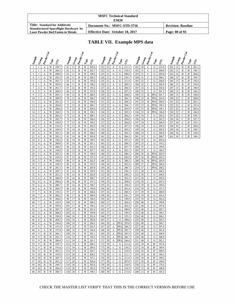
MSFC Technical Standard EM20
Title: Standard for Additively Manufactured Spaceflight Hardware by Laser Powder Bed Fusion in Metals
Document No.: MSFC-STD-3716 Revision: Baseline
Effective Date: October 18, 2017 Page: 80 of 93
CHECK THE MASTER LIST VERIFY THAT THIS IS THE CORRECT VERSION BEFORE USE
TABLE VII. Example MPS data
Sam
ple
Gro
up
Pow
der
Lot
Typ
e
UT
S
Sam
ple
Gro
up
Pow
der
Lot
Typ
e
UT
S
Sam
ple
Gro
up
Pow
der
Lot
Typ
e
UT
S
Sam
ple
Gro
up
Pow
der
Lot
Typ
e
UT
S
Sam
ple
Gro
up
Pow
der
Lot
Typ
e
UT
S
1 1 A W 198.7 61 11 B W 202.4 121 21 A G 211.1 181 30 C G 212.6 241 12 B IF 201.32 1 A W 206.3 62 11 B W 202.7 122 21 A G 210.3 182 31 C G 204.0 242 12 B IF 198.73 1 A W 200.9 63 11 B W 198.6 123 21 A G 208.8 183 31 C G 203.0 243 12 B IF 204.64 1 A W 201.5 64 11 B W 202.5 124 21 A G 210.1 184 31 C G 200.1 244 13 B IF 194.75 1 A W 202.7 65 11 B W 195.4 125 21 A G 211.9 185 32 C G 204.0 245 13 B IF 192.46 1 A W 203.0 66 11 B W 198.2 126 21 A G 209.5 186 32 C G 202.9 246 13 B IF 195.07 2 A W 201.7 67 12 B W 193.2 127 22 A G 206.5 187 32 C G 202.8 247 13 B IF 196.98 2 A W 200.9 68 12 B W 192.9 128 22 A G 207.2 188 32 C G 201.5 248 13 B IF 186.29 2 A W 205.1 69 12 B W 200.5 129 22 A G 204.0 189 33 B PPA 201.7 249 13 B IF 196.810 2 A W 209.9 70 12 B W 204.3 130 22 A G 206.7 190 33 B PPA 203.8 250 22 C IF 208.011 2 A W 201.2 71 12 B W 196.9 131 22 A G 204.3 191 33 B PPA 200.5 251 22 C IF 201.112 2 A W 203.0 72 12 B W 204.7 132 22 A G 204.1 192 33 B PPA 198.3 252 22 C IF 197.413 3 A W 206.6 73 13 B W 204.4 133 22 A G 203.9 193 33 B PPA 198.1 253 22 C IF 203.614 3 A W 208.5 74 13 B W 198.1 134 22 A G 205.5 194 33 B PPA 196.9 254 22 C IF 186.915 3 A W 202.6 75 13 B W 200.1 135 22 A G 206.2 195 34 C G 203.2 255 22 C IF 194.716 3 A W 202.7 76 13 B W 206.4 136 22 A G 204.8 196 34 C G 202.2 256 34 C IF 187.717 3 A W 199.9 77 13 B W 199.2 137 22 A G 206.8 197 34 C G 204.9 257 34 C IF 193.118 3 A W 210.2 78 13 B W 202.9 138 22 A G 207.5 198 34 C G 205.9 258 34 C IF 204.619 4 A W 198.9 79 14 B W 196.5 139 22 A G 205.2 199 34 C G 202.8 259 34 C IF 198.720 4 A W 202.2 80 14 B W 200.2 140 22 A G 205.3 200 34 C G 204.0 260 34 C IF 194.921 4 A W 202.1 81 14 B W 205.0 141 22 A G 206.5 201 35 C G 200.7 261 34 C IF 198.122 4 A W 196.2 82 14 B W 199.3 142 22 A G 207.2 202 35 C G 203.623 4 A W 200.0 83 14 B W 201.1 143 22 A G 208.3 203 35 C G 193.224 4 A W 200.2 84 14 B W 201.3 144 22 A G 207.7 204 35 C G 199.825 5 A W 198.9 85 15 B W 207.7 145 23 A G 202.1 205 35 C G 188.526 5 A W 203.2 86 15 B W 196.9 146 23 A G 200.1 206 36 B PPA 202.927 5 A W 195.8 87 15 B W 197.2 147 23 A G 202.9 207 36 B PPA 203.228 5 A W 196.8 88 15 B W 202.5 148 23 A G 200.3 208 36 B PPA 205.929 5 A W 198.5 89 15 B W 193.5 149 24 C G 202.4 209 37 C PPA 200.630 5 A W 201.3 90 15 B W 203.0 150 24 C G 200.7 210 37 C PPA 200.231 6 A W 205.7 91 16 B W 199.9 151 24 C G 196.1 211 38 C G 204.232 6 A W 201.2 92 16 B W 202.8 152 24 C G 204.2 212 38 C G 204.433 6 A W 206.8 93 16 B W 200.7 153 25 C G 202.3 213 38 C G 202.034 6 A W 200.4 94 16 B W 197.2 154 25 C G 204.8 214 38 C G 201.935 6 A W 200.7 95 16 B W 196.7 155 25 C G 198.4 215 39 D G 199.436 6 A W 204.5 96 16 B W 199.0 156 26 C G 201.4 216 39 D G 197.537 7 A W 195.2 97 17 B W 204.6 157 26 C G 200.3 217 39 D G 200.938 7 A W 200.2 98 17 B W 200.9 158 26 C G 201.1 218 39 D G 201.639 7 A W 204.6 99 17 B W 196.9 159 26 C G 199.9 219 39 D G 202.440 7 A W 195.9 100 17 B W 208.4 160 27 C G 204.4 220 40 E G 199.041 7 A W 203.0 101 17 B W 196.3 161 27 C G 202.2 221 40 E G 197.842 7 A W 205.7 102 17 B W 201.9 162 27 C G 200.8 222 40 E G 202.743 8 A W 200.4 103 18 C W 199.9 163 27 C G 199.5 223 40 E G 198.144 8 A W 198.4 104 18 C W 201.6 164 27 C G 195.1 224 40 E G 204.145 8 A W 204.3 105 18 C W 202.0 165 27 C G 200.6 225 40 E G 202.346 8 A W 196.0 106 18 C W 204.3 166 28 A PPA 205.0 226 40 E G 206.747 8 A W 197.4 107 18 C W 203.5 167 28 A PPA 208.2 227 40 E G 207.448 8 A W 197.0 108 18 C W 196.4 168 28 A PPA 205.7 228 40 E G 201.849 9 B W 206.1 109 19 C W 201.1 169 29 A PPA 205.5 229 40 E G 208.950 9 B W 203.3 110 19 C W 199.3 170 29 A PPA 206.7 230 40 E G 208.951 9 B W 200.4 111 19 C W 201.1 171 29 A PPA 206.0 231 40 E G 202.152 9 B W 194.7 112 19 C W 204.3 172 30 C G 211.4 232 10 B IF 187.453 9 B W 191.6 113 19 C W 204.5 173 30 C G 210.2 233 10 B IF 189.954 9 B W 201.5 114 19 C W 202.7 174 30 C G 210.9 234 10 B IF 209.955 10 B W 195.0 115 20 C W 206.5 175 30 C G 211.1 235 10 B IF 196.356 10 B W 202.7 116 20 C W 197.1 176 30 C G 211.0 236 10 B IF 198.257 10 B W 201.2 117 20 C W 204.4 177 30 C G 207.8 237 10 B IF 194.058 10 B W 199.7 118 20 C W 202.8 178 30 C G 210.9 238 12 B IF 178.459 10 B W 204.4 119 20 C W 202.4 179 30 C G 210.3 239 12 B IF 180.960 10 B W 200.7 120 20 C W 198.5 180 30 C G 213.0 240 12 B IF 185.2
MSFC Technical Standard EM20
Title: Standard for Additively Manufactured Spaceflight Hardware by Laser Powder Bed Fusion in Metals
Document No.: MSFC-STD-3716 Revision: Baseline
Effective Date: October 18, 2017 Page: 81 of 93
CHECK THE MASTER LIST VERIFY THAT THIS IS THE CORRECT VERSION BEFORE USE
The first example is a review of the MPS data set to determine the suitability of using the wrought product form A-basis UTS value of 180 as the design UTS value for the L-PBF product form while meeting the requirements of Section 7.2, on tensile properties. The design value generated from the MPS should account for all types of variability that are not isolated and considered as an independent influence factor. A direct evaluation of the sources of variability using a dedicated design of experiments is the best way to determine what sources of variability are appropriate to combine into a general design value. In this example, common L-PBF sources of variability are incorporated into the room temperature, smooth, UTS design value. These sources of variability include location in the build volume, scan path dependencies, and powder bed thermal history. These sources are deemed acceptable to evaluate collectively because they were shown to have limited influence at the time the process was qualified as a QMP, primarily due to the tolerance of the alloy to such variations and the thoroughness of the microstructural evolution from thermal processing. From an engineering perspective, it is the appropriate pragmatic choice to incorporate these variations into a single design value versus establishing a framework of design values to account for such variables. There may be materials sufficiently sensitive to one or more of these variables such as powder bed thermal history that the effects cannot be conveniently grouped unless there are additional, specific process controls. Therefore, to account for all such variability in the design value, all compatible data from the MPS should be included in the evaluation. In this example, the collected data includes process witness data, pre-production article mechanical data, and the general characterization data from all material, build, and heat treat lots. In Table VII, this collection includes all data with the exception of the influence factor data, which is suspected to have a source of variability that is to be isolated and evaluated separately. Thus, the set of data for design value assessment is the first 231 values in the UTS column of Table VII. As with all material property data with the potential for trends from sources such as lot variability (powder lots, heat treat lots, or build lots), a review of the data for regression trends and combinability needs to occur as recommended in the data analysis guidelines of MMPDS. The data of this example are well behaved, combinable, and do not show any regressions. The direct computation methods of the MMPDS are appropriate to determine the T99 values for this design value assessment for UTS. Evaluation of the Pearson (three-parameter gamma) and Weibull distributions using the appropriate modified Anderson-Darling tests show that either distribution is acceptable. The Pearson model gives a T99 for the UTS of 191.0. The data and fit are illustrated in Figure 5.

MSFC Technical Standard EM20
Title: Standard for Additively Manufactured Spaceflight Hardware by Laser Powder Bed Fusion in Metals
Document No.: MSFC-STD-3716 Revision: Baseline
Effective Date: October 18, 2017 Page: 82 of 93
CHECK THE MASTER LIST VERIFY THAT THIS IS THE CORRECT VERSION BEFORE USE
FIGURE 5. Substantiation of design value from MPS data Evaluating against the requirements of Section 7.2, for tensile properties in L-PBF materials:
a. The proposed design value (180) is less than the T99 of the modeled distribution (191.0).
b. Lot requirements do not fully meet the intent of section 5.4.2.1 for a fully mature MPS because lots D and E are not yet represented equivalently in the data population to lots A, B, and C. There are adequate build/heat treat lots. The example MPS qualifies as a Provisional MPS.
c. There are more than the minimum required 100 degrees of freedom in the evaluation.
d. Because there are fewer than 300 degrees of freedom in the evaluation, the Design Value Margin is required to exceed the estimated coefficient of variation (CV) of the data population. From the Pearson model, the mean value is 202.4 and the standard deviation is 4.23, giving CV = 2.1%. (The design value must be less than 191.0*(1-0.021) = 187.0.) The Design Value Margin in this case is 5.9% which exceeds the CV. See Figure 5.
e. The MPS is properly maintained by the CEO.
This evaluation illustrates that the use of 180 as the UTS design value is supported by the available data. Based on this assessment, the UTS value from the Provisional MPS could be used for Class B parts with a part-specific MUA. (See section 5.4.2.1). Additional data from lots D
MSFC Technical Standard EM20
Title: Standard for Additively Manufactured Spaceflight Hardware by Laser Powder Bed Fusion in Metals
Document No.: MSFC-STD-3716 Revision: Baseline
Effective Date: October 18, 2017 Page: 83 of 93
CHECK THE MASTER LIST VERIFY THAT THIS IS THE CORRECT VERSION BEFORE USE
and E would mature the MPS to the balanced, five-lot requirement and permit full use. Note that feedstock re-use, section 5.4.2.2, is not addressed in this example.
As a general note, though evaluation of this data set could support a design value greater than the 180 specification minimum value of the wrought product form of the alloy, taking advantage of this would not be advised, nor likely approved, given the lack of maturity of the L-PBF process.
The next example describes the development of a PCRD from the MPS to use in witness acceptance testing of builds. The PCRD itself is merely a statistical model of the standardized witness test data from which acceptance criteria are generated. The goal of the PCRD is to protect the process from drift through systemic process control by maintaining tensile properties in-family with those of the MPS. The use of the PCRD (and/or control chart methods, which are not addressed in this example) in witness testing justifies the continued validity of the design values from ongoing L-PBF operations as well as other accommodations this MSFC Technical Standard makes to the MMPDS framework for material properties, such as reduced material lot requirements. It is clear from Figure 5 that acceptance of witness tests for UTS using only the design value of 180 would accept data out-of-family with the MPS, well below the tail of the existing data. Such out-of-family witness values have implications not only for UTS but also other associated design values such as fatigue performance.
The objectives in generating a design value from the MPS are to capture all forms of potential variation that are not studied independently as influence factors and to model that data with particular care in the lower tail to achieve reliable T99 estimates. The objectives in development of the PCRD are different. The goal of the PCRD is to standardize the measurement (to the degree possible) using consistent test geometry and L-PBF scan methods to minimize variability in the metric, thereby increasing the ability to detect systemic process drift. While the lower tail of the PCRD distribution may be used in acceptance criteria, its resolution is not as critical. A good overall quality of fit to define the “family” of MPS witness data is most important. Finally, the product of the PCRD is a set of witness test acceptance criteria that identify out-of-family witness test results while emphasizing simplicity and minimizing the potential for false negative calls. Similar to control chart theory, the PCRD acceptance criteria should address, in some form, the minimum acceptable value, mean, and variance of the set of witness specimens when evaluating a build. To develop this example PCRD, only the UTS values from witness data (type W) from Table VII are considered. To develop a fit to this data (the fit is the PCRD), the guidance for reviewing test data quality and determining distribution fits from the MMPDS is recommended. For the PCRD, more latitude in choice of distributions is allowed than considered by MMPDS. Any fit that can be demonstrated to model the data appropriately may be used. In this example, a variety of distributions were found to successfully model the data; however, since the fit of the normal distribution is acceptable, it is chosen for simplicity. Figure 6, PCRD from Witness Data with Defined Witness Acceptance Criteria, illustrates the PCRD fit. The mean of the PCRD (pcrd) is pcrd = 201.0 and the standard distribution of the PCRD (pcrd) is pcrd = 3.67. These two values

MSFC Technical Standard EM20
Title: Standard for Additively Manufactured Spaceflight Hardware by Laser Powder Bed Fusion in Metals
Document No.: MSFC-STD-3716 Revision: Baseline
Effective Date: October 18, 2017 Page: 84 of 93
CHECK THE MASTER LIST VERIFY THAT THIS IS THE CORRECT VERSION BEFORE USE
define the PCRD in this example. The subset of witness test results in the MPS will grow as the MPS and PCRD are maintained and updated. See section 5.4.5.1 on PCRD maintenance. This MSFC Technical Standard does not specify the form of acceptance criteria generated from the PCRD. This is left to the discretion of the CEO and is documented in the AMCP. In this example, the following criteria are used to accept the witness set of six UTS values for the stand-alone witness requirements of section 6.2.2.1:
a. All UTS values > T99 of the PCRD (criteria address minimum value).
b. Mean UTS of witness set (w) > T90 of the PCRD (criteria address low mean).
c. Mean UTS of witness set (w) < pcrd + (3 × pcrd ) (criteria address high mean).
d. Standard deviation of UTS in witness set (w) < 1.5 × pcrd (criteria address variance). These rules would be expected to remain constant, though the acceptance values may change as the MPS and PCRD are maintained with additional data. For the current state of the PCRD in this example, the acceptance criteria result the following simple evaluations:
a. No UTS value < 191.3.
b. w > 195.5.
c. w < 212.1.
d. w < 5.5.
The criteria governing high mean values are in place for alloys that suffer other property debits when strength is too high, for example, loss of toughness or ductility. Examples of such alloys include 17-4PH stainless steel or Ti-6AL-4V. Failure of these witness acceptance criteria are cause for a non-conformance in the QMS requiring engineering review, not necessarily part rejection. Resolution of the non-conformance and its cause determines the fate of the part.
Figure 6 illustrates these acceptance criteria.
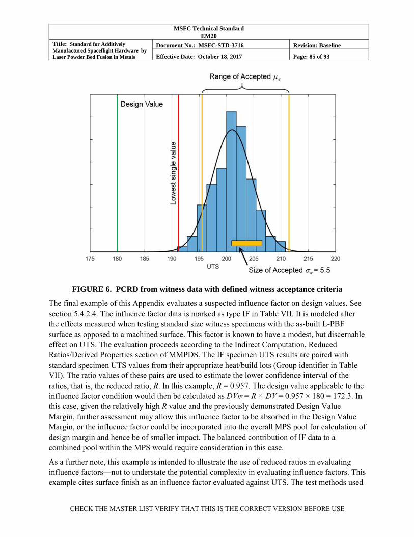
MSFC Technical Standard EM20
Title: Standard for Additively Manufactured Spaceflight Hardware by Laser Powder Bed Fusion in Metals
Document No.: MSFC-STD-3716 Revision: Baseline
Effective Date: October 18, 2017 Page: 85 of 93
CHECK THE MASTER LIST VERIFY THAT THIS IS THE CORRECT VERSION BEFORE USE
FIGURE 6. PCRD from witness data with defined witness acceptance criteria
The final example of this Appendix evaluates a suspected influence factor on design values. See section 5.4.2.4. The influence factor data is marked as type IF in Table VII. It is modeled after the effects measured when testing standard size witness specimens with the as-built L-PBF surface as opposed to a machined surface. This factor is known to have a modest, but discernable effect on UTS. The evaluation proceeds according to the Indirect Computation, Reduced Ratios/Derived Properties section of MMPDS. The IF specimen UTS results are paired with standard specimen UTS values from their appropriate heat/build lots (Group identifier in Table VII). The ratio values of these pairs are used to estimate the lower confidence interval of the ratios, that is, the reduced ratio, R. In this example, R = 0.957. The design value applicable to the influence factor condition would then be calculated as DVIF = R × DV = 0.957 × 180 = 172.3. In this case, given the relatively high R value and the previously demonstrated Design Value Margin, further assessment may allow this influence factor to be absorbed in the Design Value Margin, or the influence factor could be incorporated into the overall MPS pool for calculation of design margin and hence be of smaller impact. The balanced contribution of IF data to a combined pool within the MPS would require consideration in this case.
As a further note, this example is intended to illustrate the use of reduced ratios in evaluating influence factors—not to understate the potential complexity in evaluating influence factors. This example cites surface finish as an influence factor evaluated against UTS. The test methods used

MSFC Technical Standard EM20
Title: Standard for Additively Manufactured Spaceflight Hardware by Laser Powder Bed Fusion in Metals
Document No.: MSFC-STD-3716 Revision: Baseline
Effective Date: October 18, 2017 Page: 86 of 93
CHECK THE MASTER LIST VERIFY THAT THIS IS THE CORRECT VERSION BEFORE USE
to determine the effect of such factors need to be well considered. For example, depending upon the mechanism influencing UTS, the length scale associated with the L-PBF surface finish would likely contribute to the magnitude of the influence; that is, the effects are likely a function of test specimen size, and correspondingly, the thickness of a part with the as-built L-PBF surface.
MSFC Technical Standard EM20
Title: Standard for Additively Manufactured Spaceflight Hardware by Laser Powder Bed Fusion in Metals
Document No.: MSFC-STD-3716 Revision: Baseline
Effective Date: October 18, 2017 Page: 87 of 93
CHECK THE MASTER LIST VERIFY THAT THIS IS THE CORRECT VERSION BEFORE USE
APPENDIX D. THE CRYPTOGRAPHIC HASH
This Appendix is not a mandatory part of the standard. The information contained herein is intended for guidance only.
This Appendix provides a brief background on the use of digital hashes for configuration and integrity management of the files comprising the DPD of L-PBF parts.
This MSFC Technical Standard uses the cryptographic hash (CH) to unambiguously identify files critical to the QPP once the files have been finalized and “locked” in the QMS. A hash function maps data of an arbitrary size such as a multi-gigabyte L-PBF build file to a very small, fixed size called a message digest or hash value. For cryptographic hashes, the hash algorithm is a one-way function that cannot be inverted. The inability to invert the hash to identify its source is the value of the CH for security purposes such as passwords or digital signatures. While file security is a clear benefit to the use of the CH in this MSFC Technical Standard, the primary purpose it serves is to create a simple “fingerprint” of the content of a file for managing its configuration. Most formal file configuration management software uses the CH in the background to manage and identify file versions. The CH will identify any change to the content of a file by producing a different hash value. When L-PBF DPD files are stored within a configuration management system with file version tracking, there is no need for externally evaluating and recording the CH for the files; however, when files are removed from the configuration management environment, a method to track and confirm the integrity of the file is required. There are a number of situations where files may be removed from the configuration management system, for example, to be further processed on a local computer, to move to an L-PBF machine, or to be provided to an L-PBF process vendor.
The CH function recommended by this MSFC Technical Standard is Secure Hash Algorithm-1 (SHA-1). See National Institute of Standards and Technology Federal Information Processing Standard (FIPS) Publication (PUB) 180-4, Secure Hash Standard FIPS PUB 180-4. This algorithm produces a 160 bit (40 character) hexadecimal hash value. The SHA-1 algorithm can operate on any file (or even a text string). Examples of SHA-1 hash values are shown below for the text strings “Laser Powder Bed Fusion” and “Laser Powder bed Fusion.”
Laser Powder Bed Fusion 85BB98E57467A82B39042331195E611F4A2EE823
Laser Powder bed Fusion 1DEB28D58F7F7EB55165AEC703C3DBA218B962F0
When the QPP is finalized, the SHA-1 hash for each file that is part of the L-PBF DPD is created and tracked as part of the QPP with the QMS. This includes any files needed for building the part or the re-creation of the build state such as CAD files, STL files, support structure files, or part/build assemblies. Recording the hash allows quality assurance to verify the integrity of the
MSFC Technical Standard EM20
Title: Standard for Additively Manufactured Spaceflight Hardware by Laser Powder Bed Fusion in Metals
Document No.: MSFC-STD-3716 Revision: Baseline
Effective Date: October 18, 2017 Page: 88 of 93
CHECK THE MASTER LIST VERIFY THAT THIS IS THE CORRECT VERSION BEFORE USE
DPD files at any time but is of particular interest after files are transferred to machines or vendors.
The SHA-1 hash algorithm has recently been found vulnerable to a collision, where two files of differing content yield the same hash value. While this is of concern for the use of SHA-1 in applications where data security is paramount, for the purposes of maintaining configuration of L-PBF files, the SHA-1 hash is acceptable. It will preclude all accidental losses of configuration such as mis-naming a file (hashes are sensitive to content, not file names), loss of data integrity in file transfer, and all but the most well-funded and coordinated malicious attack.
The SHA-1 algorithm is available through many sources for any applicable computer operating system.
MSFC Technical Standard EM20
Title: Standard for Additively Manufactured Spaceflight Hardware by Laser Powder Bed Fusion in Metals
Document No.: MSFC-STD-3716 Revision: Baseline
Effective Date: October 18, 2017 Page: 89 of 93
CHECK THE MASTER LIST VERIFY THAT THIS IS THE CORRECT VERSION BEFORE USE
APPENDIX E. REFERENCE DOCUMENTS
This Appendix is not a mandatory part of the standard. The information contained herein is intended for guidance only.
The documents listed in this Appendix have been referenced within this MSFC Technical Standard as examples or recommendations. These documents are not directly applicable to fulfilling the requirements of this MSFC Technical Standard.
Government Documents:
FIPS PUB 180-4 Secure Hash Standard (SHS) Federal Information Processing Standards Publication, National Institutes of Standards and Technology, 2012
NPD 8730.5 NASA Quality Assurance Program Policy
NRRS 1441.1 NASA Records Retention Schedules
NASA-STD-5009 Nondestructive Evaluation Requirements for Fracture-Critical Metallic Components
NASA-STD-5012 Strength and Life Assessment Requirements For Liquid Fueled Space Propulsion System Engines
MSFC-SPEC-164 Cleanliness of Components for Use in Oxygen, Fuel, and Pneumatic Systems, Specification for
Non-Government Documents:
ASTM E8/E8M Standard Test Methods for Tension Testing of Metallic Materials
ASTM E466 Standard Practice for Conducting Force Controlled Constant Amplitude Axial Fatigue Tests of Metallic Materials
ASTM E606/E606M Standard Test Method for Strain-Controlled Fatigue Testing
ASTM E1820 Standard Test Method for Measurement of Fracture Toughness
ASTM E2281 Standard Practice for Process Capability and Performance Measurement
ASTM E2587 Standard Practice for Use of Control Charts in Statistical Process Control
CMH-17 Composite Materials Handbook - 17
MSFC Technical Standard EM20
Title: Standard for Additively Manufactured Spaceflight Hardware by Laser Powder Bed Fusion in Metals
Document No.: MSFC-STD-3716 Revision: Baseline
Effective Date: October 18, 2017 Page: 90 of 93
CHECK THE MASTER LIST VERIFY THAT THIS IS THE CORRECT VERSION BEFORE USE
DOT/FAA/AR-03/19 Material Qualification and Equivalency for Polymer Matrix Composite Material Systems: Updated Procedure (2003)
IEST-STD-CC1246 Product Cleanliness Levels - Applications, Requirements, and Determination
ISO/ASTM 52921 Standard Terminology for Additive Manufacturing-Coordinate Systems and Test Methodologies
MMPDS Metallic Materials Properties Development and Standardization
SAE AMS2175 Castings, Classification and Inspection of
SAE AS9102 Aerospace First Article Inspection Requirement
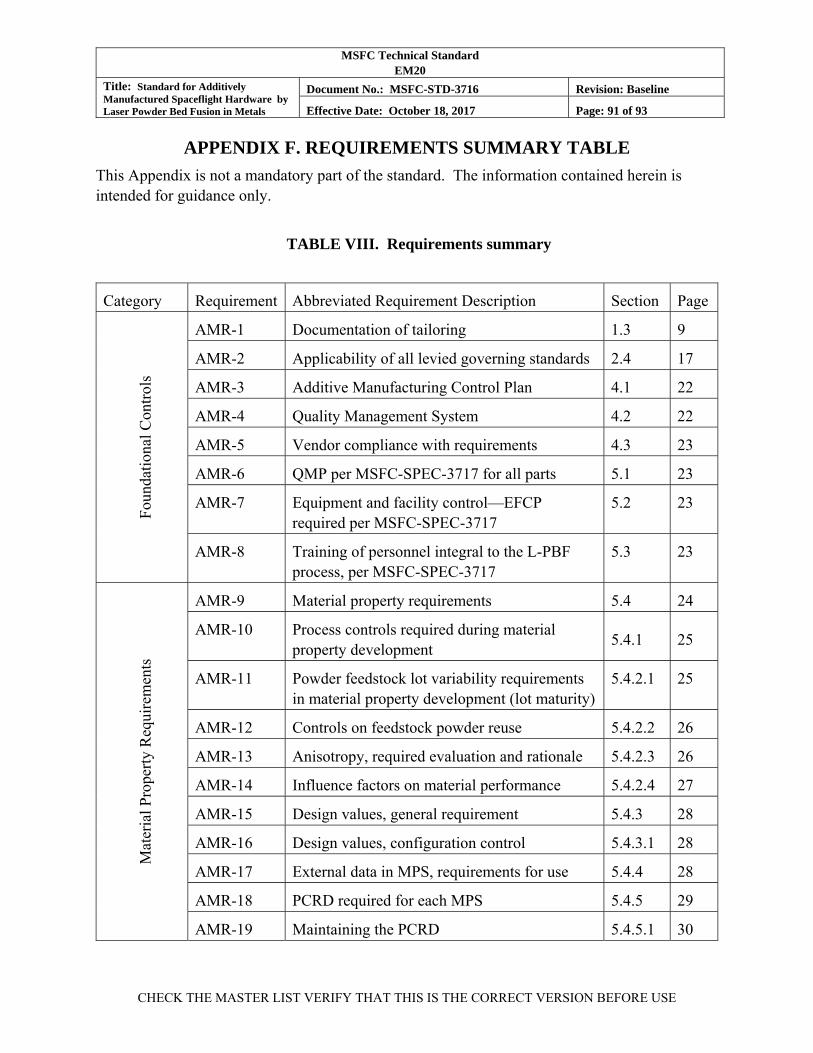
MSFC Technical Standard EM20
Title: Standard for Additively Manufactured Spaceflight Hardware by Laser Powder Bed Fusion in Metals
Document No.: MSFC-STD-3716 Revision: Baseline
Effective Date: October 18, 2017 Page: 91 of 93
CHECK THE MASTER LIST VERIFY THAT THIS IS THE CORRECT VERSION BEFORE USE
APPENDIX F. REQUIREMENTS SUMMARY TABLE
This Appendix is not a mandatory part of the standard. The information contained herein is intended for guidance only.
TABLE VIII. Requirements summary
Category Requirement Abbreviated Requirement Description Section Page
Fou
ndat
iona
l Con
trol
s
AMR-1 Documentation of tailoring 1.3 9
AMR-2 Applicability of all levied governing standards 2.4 17
AMR-3 Additive Manufacturing Control Plan 4.1 22
AMR-4 Quality Management System 4.2 22
AMR-5 Vendor compliance with requirements 4.3 23
AMR-6 QMP per MSFC-SPEC-3717 for all parts 5.1 23
AMR-7 Equipment and facility control—EFCP required per MSFC-SPEC-3717
5.2 23
AMR-8 Training of personnel integral to the L-PBF process, per MSFC-SPEC-3717
5.3 23
Mat
eria
l Pro
pert
y R
equi
rem
ents
AMR-9 Material property requirements 5.4 24
AMR-10 Process controls required during material property development
5.4.1 25
AMR-11 Powder feedstock lot variability requirements in material property development (lot maturity)
5.4.2.1 25
AMR-12 Controls on feedstock powder reuse 5.4.2.2 26
AMR-13 Anisotropy, required evaluation and rationale 5.4.2.3 26
AMR-14 Influence factors on material performance 5.4.2.4 27
AMR-15 Design values, general requirement 5.4.3 28
AMR-16 Design values, configuration control 5.4.3.1 28
AMR-17 External data in MPS, requirements for use 5.4.4 28
AMR-18 PCRD required for each MPS 5.4.5 29
AMR-19 Maintaining the PCRD 5.4.5.1 30
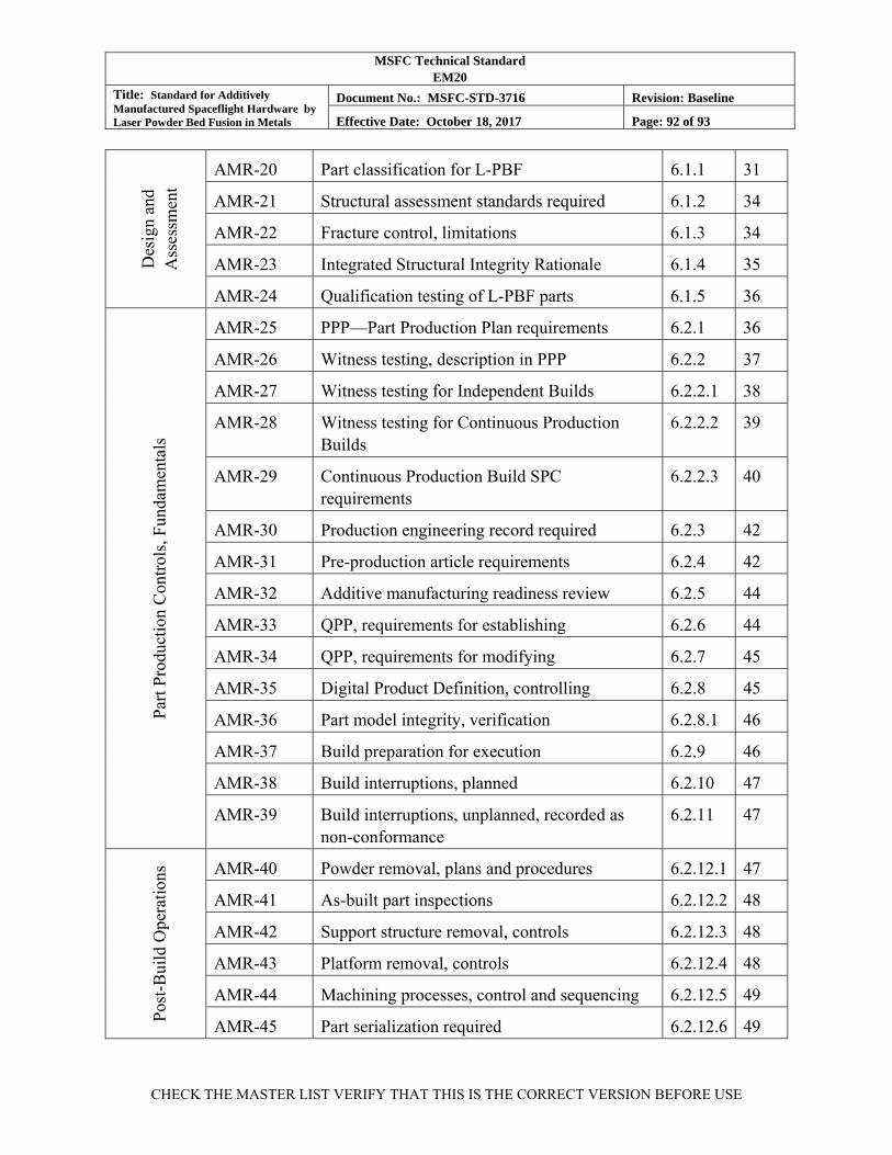
MSFC Technical Standard EM20
Title: Standard for Additively Manufactured Spaceflight Hardware by Laser Powder Bed Fusion in Metals
Document No.: MSFC-STD-3716 Revision: Baseline
Effective Date: October 18, 2017 Page: 92 of 93
CHECK THE MASTER LIST VERIFY THAT THIS IS THE CORRECT VERSION BEFORE USE
Des
ign
and
Ass
essm
ent
AMR-20 Part classification for L-PBF 6.1.1 31
AMR-21 Structural assessment standards required 6.1.2 34
AMR-22 Fracture control, limitations 6.1.3 34
AMR-23 Integrated Structural Integrity Rationale 6.1.4 35
AMR-24 Qualification testing of L-PBF parts 6.1.5 36
Par
t Pro
duct
ion
Con
trol
s, F
unda
men
tals
AMR-25 PPP—Part Production Plan requirements 6.2.1 36
AMR-26 Witness testing, description in PPP 6.2.2 37
AMR-27 Witness testing for Independent Builds 6.2.2.1 38
AMR-28 Witness testing for Continuous Production Builds
6.2.2.2 39
AMR-29 Continuous Production Build SPC requirements
6.2.2.3 40
AMR-30 Production engineering record required 6.2.3 42
AMR-31 Pre-production article requirements 6.2.4 42
AMR-32 Additive manufacturing readiness review 6.2.5 44
AMR-33 QPP, requirements for establishing 6.2.6 44
AMR-34 QPP, requirements for modifying 6.2.7 45
AMR-35 Digital Product Definition, controlling 6.2.8 45
AMR-36 Part model integrity, verification 6.2.8.1 46
AMR-37 Build preparation for execution 6.2.9 46
AMR-38 Build interruptions, planned 6.2.10 47
AMR-39 Build interruptions, unplanned, recorded as non-conformance
6.2.11 47
Pos
t-B
uild
Ope
rati
ons AMR-40 Powder removal, plans and procedures 6.2.12.1 47
AMR-41 As-built part inspections 6.2.12.2 48
AMR-42 Support structure removal, controls 6.2.12.3 48
AMR-43 Platform removal, controls 6.2.12.4 48
AMR-44 Machining processes, control and sequencing 6.2.12.5 49
AMR-45 Part serialization required 6.2.12.6 49
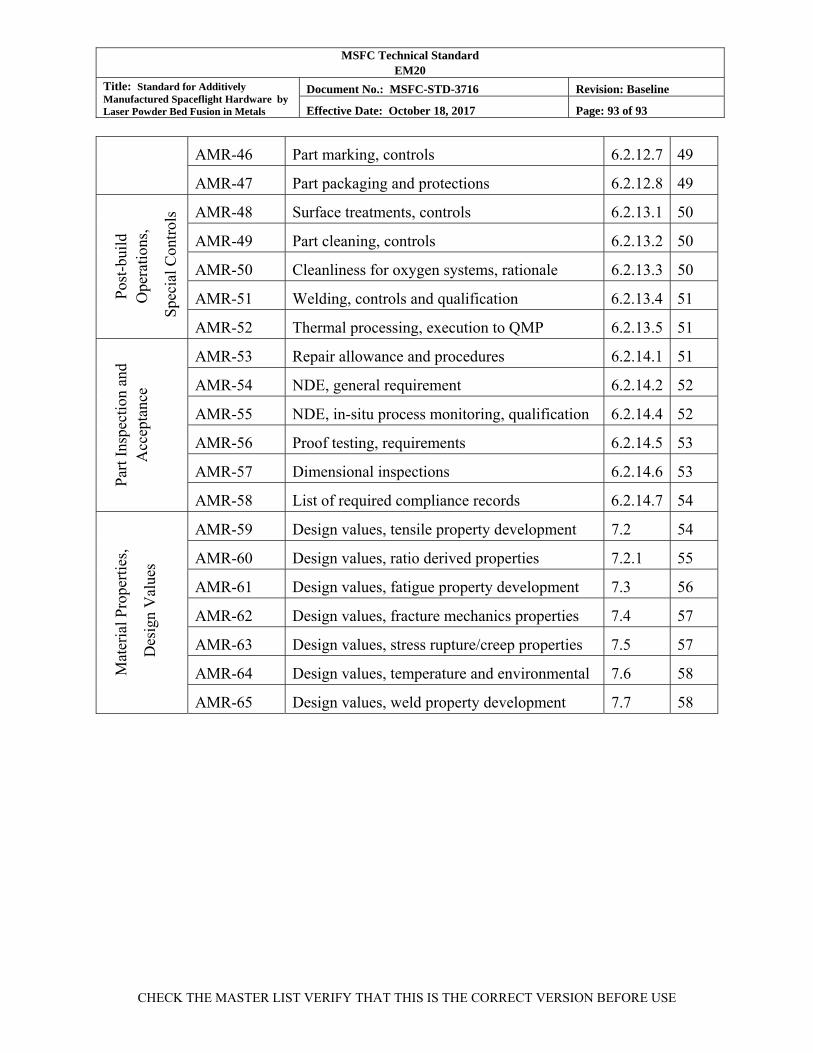
MSFC Technical Standard EM20
Title: Standard for Additively Manufactured Spaceflight Hardware by Laser Powder Bed Fusion in Metals
Document No.: MSFC-STD-3716 Revision: Baseline
Effective Date: October 18, 2017 Page: 93 of 93
CHECK THE MASTER LIST VERIFY THAT THIS IS THE CORRECT VERSION BEFORE USE
AMR-46 Part marking, controls 6.2.12.7 49
AMR-47 Part packaging and protections 6.2.12.8 49
Pos
t-bu
ild
Ope
rati
ons,
Spe
cial
Con
trol
s AMR-48 Surface treatments, controls 6.2.13.1 50
AMR-49 Part cleaning, controls 6.2.13.2 50
AMR-50 Cleanliness for oxygen systems, rationale 6.2.13.3 50
AMR-51 Welding, controls and qualification 6.2.13.4 51
AMR-52 Thermal processing, execution to QMP 6.2.13.5 51
Par
t Ins
pect
ion
and
Acc
epta
nce
AMR-53 Repair allowance and procedures 6.2.14.1 51
AMR-54 NDE, general requirement 6.2.14.2 52
AMR-55 NDE, in-situ process monitoring, qualification 6.2.14.4 52
AMR-56 Proof testing, requirements 6.2.14.5 53
AMR-57 Dimensional inspections 6.2.14.6 53
AMR-58 List of required compliance records 6.2.14.7 54
Mat
eria
l Pro
pert
ies,
Des
ign
Val
ues
AMR-59 Design values, tensile property development 7.2 54
AMR-60 Design values, ratio derived properties 7.2.1 55
AMR-61 Design values, fatigue property development 7.3 56
AMR-62 Design values, fracture mechanics properties 7.4 57
AMR-63 Design values, stress rupture/creep properties 7.5 57
AMR-64 Design values, temperature and environmental 7.6 58
AMR-65 Design values, weld property development 7.7 58