Embed Size (px)
Citation preview

VIESMANN VITOPLEX 100Standard oil/gas boiler
110 to 620 kW
VITOPLEX 100 Type PV1
Standard oil/gas boilerFor operation with a constant boiler water temperature.
5822 518 GB 5/2015
DatasheetPart no. and prices: see pricelist
■ Standard seasonal efficiency [to DIN]: 86 % (Hs) [gross cv] / 92 %(Hi) [net cv].
■ Thermostatic Vitotronic 100 control unit for single boiler systems.■ Extendable to a multi boiler system with the Vitotronic control sys-
tem.
■ No minimum heating water flow rate required.■ High operational reliability and safety through the use of high qual-
ity materials and advanced welding processes.
A Wide water galleries and large water content ensure excellentnatural circulation and easy hydraulic connection
B Highly effective thermal insulationC Vitotronic control unit – intelligent and easy to install, operate
and maintainD Thermal insulationE Combustion chamberF Second hot gas flue
Benefits at a glance
2 VIESMANN VITOPLEX 100
5822
518
GB

Specification
Rated heating output kW 150 200 250 310 410 500 620Rated heating input range from kW 121 166 221 276 342 441 551 to kW 165 220 275 341 440 550 682Product ID CE-0085BP0365Permiss. flow temperature(= safety temperature)
°C 110
Permiss. operating pressure bar 5 MPa 0.5Pressure drop on the hot gas side Pa 60 120 130 230 250 230 310 mbar 0.6 1.2 1.3 2.3 2.5 2.3 3.1Boiler body dimensions Length (dim. r)*1 mm 1245 1385 1385 1565 1730 1730 1830Width (dim. e) mm 650 650 730 730 800 800 865Height (incl. connectors) (dim. l) mm 1120 1120 1195 1195 1365 1365 1420Overall dimensions Total length (dim. s) mm 1350 1490 1490 1670 1840 1840 1940Total width (dim. f) mm 800 800 880 880 950 950 1015Total height (dim. b) mm 1290 1290 1360 1360 1530 1530 1585Service height (control unit) (dim. a) mm 1460 1460 1530 1530 1700 1700 1760Height of anti-vibration boiler supports (underload)
mm 37 37 37 37 37 37 37
Foundation Length mm 1000 1100 1100 1300 1400 1400 1500Width mm 800 800 900 900 950 950 1050Combustion chamber diameter mm 460 460 500 500 585 585 640Combustion chamber length mm 865 1005 1005 1185 1305 1305 1405Weight boiler body kg 370 415 475 525 730 785 940Total weightBoiler with thermal insulation and boiler controlunit
kg 415 460 525 580 790 845 1005
Boiler water content l 200 230 280 340 490 460 535Boiler connections Boiler flow and return PN 6 DN 65 65 65 65 100 100 100Safety connection (safety valve) R (male thread) 1¼ 1¼ 1¼ 1¼ 1½ 1½ 1½Drain connection R (male thread) 1¼ 1¼ 1¼ 1¼ 1¼ 1¼ 1¼Flue gas parameters*2 Temperature (at boiler water temperature75 °C)
– at rated heating output °C 215 215 215 215 215 215 215– at partial load °C 140 140 140 140 140 140 140Mass flow rate (for fuel oil EL and natural gas) – at rated heating output kg/h 230 307 384 476 614 767 951– at partial load kg/h 138 184 171 286 369 460 571Required draught Pa/mbar 0 0 0 0 0 0 0Flue gas connection Ø mm 180 180 200 200 250 250 250Standard seasonal efficiency [to DIN]for heating system temperature 75/60 °C
% 86 (Hs) [gross cv] / 92 (Hi) [net cv]
Standby loss qB,70 % 0.45 0.40 0.35 0.30 0.25
NoteFor the specification of components in Viessmann system design,see separate datasheets.
*1 Boiler door removed.*2 Values for calculating the size of the flue system to EN 13384 relative to 13 % CO2 for fuel oil EL and 10 % CO2 for natural gas. Flue gas
temperatures captured as gross values at 20 °C combustion air temperature.The details for partial load refer to an output of 60 % of the rated heating output. If the partial load differs from that stated above (subject tooperating mode), calculate the flue gas mass flow rate accordingly.
Specification - Vitoplex 100
VITOPLEX 100 VIESMANN 3
5822
518
GB
Dimensions
h
o
b
a
e
d
SCH
q E
c
KTÜk
g
f
KRKVSA KTS
p
n
r
m
AGA R
l
s
AGA Flue outletE Drain outletKR Boiler returnKTS Boiler water temperature sensorKTÜ Boiler door
KV Boiler flowR Cleaning apertureSA Safety connection (safety valve)SCH Inspection port
DimensionsRated heating output kW 150 200 250 310 410 500 620a mm 1460 1460 1530 1530 1700 1700 1760b mm 1290 1290 1360 1360 1530 1530 1585c mm 1058 1058 1130 1130 1300 1300 1356d mm 400 400 420 420 465 465 495e mm 650 650 730 730 800 800 865f mm 800 800 880 880 950 950 1015g mm 670 810 810 976 1051 1051 1152h mm 410 480 480 563 611 611 662k mm 150 150 150 150 171 171 172l mm 1120 1120 1195 1195 1365 1365 1420m mm 833 833 886 886 1017 1017 1058n mm 123 123 122 122 124 124 125o mm 110 110 110 110 130 130 130p (length of base rails) mm 931 1071 1071 1251 1375 1375 1476q mm 203 203 203 203 224 224 224r (transport dimension) mm 1245 1385 1385 1565 1730 1730 1830s mm 1350 1490 1490 1670 1840 1840 1940
Dim. a: Height with control unit in maintenance position.Dim. d: Observe the installed burner height.Dim. r: Boiler door removed.
Specification - Vitoplex 100 (cont.)
4 VIESMANN VITOPLEX 100
5822
518
GB

Siting
A
(300)
200 (100)
500 (50)
400a
b
500 (50)
B
C
A BoilerB BurnerC Anti-vibration boiler supports
To enable convenient installation and maintenance, observe the sta-ted clearance dimensions; where space is tight, only the minimumclearances (dimensions in brackets) need to be maintained. In thedelivered condition, the boiler door opens to the left. The hinge pinscan be repositioned so the door swings open to the right.
Rated heating output kW 150 200 250 310 410 500 620a mm 1100 1250 1500 b mm Installed burner length
Dim. a: Maintain this space in front of the boiler to enable removalof the turbulators and cleaning of the hot gas flues.
Siting■ Prevent air contamination by halogenated hydrocarbons
(e.g. as contained in sprays, paints, solvents and cleaning agents)■ Prevent very dusty conditions■ Prevent high levels of humidity■ Prevent frost and ensure good ventilation
Otherwise, the system may suffer faults and damage.In rooms where air contamination through halogenated hydrocar-bons may occur, install the boiler only if adequate measures can betaken to provide a supply of uncontaminated combustion air.
Mounting the burnerThe burner fixing hole circle, burner fixing holes and flame tubeaperture meet the requirements of EN 303-1.The burner may be mounted directly on the hinged boiler door. Alter-native burner plates can be used (see boiler accessories) if theburner dimensions differ from those listed in EN 303-1.Burner plates may be factory prepared on request (chargeableoption). If this is required, state the burner make and type whenordering.
The flame tube must protrude from the thermal insulation of theboiler door. Maintain the required minimum flame tube length of105 mm plus 50 or 75 mm (see f in table "Specification - Vitoplex100").Where a burner with a shorter flame tube is to be used, verify its per-fect function.
Specification - Vitoplex 100 (cont.)
VITOPLEX 100 VIESMANN 5
5822
518
GB
45°
cb
a
105
de
f
15°
cb
a
de
110 -500 kW 620 kW
Rated heating output kW 150 200 250 310 410 500 620a Ø mm 240 240 240 290 290 290 350b Ø mm 270 270 270 330 330 330 400c Number/thread 4/M 10 4/M 10 4/M 10 4/M 12 4/M 12 4/M 12 6/M 12d mm 400 400 420 420 465 465 495e mm 655 655 690 690 775 775 795f mm 50 50 50 50 75 75 75
Pressure drop on the heating water side
A
Flow rate in m³/h1
8
4030
20
10
543
2
1
Pres
sure
dro
p in
mba
r
2 3 4 5 6 10 20 40 60 1000.1
0.2
0.30.40.5
0.8
50
80100
B C
A Rated heating output 110 to 250 kWB Rated heating output 251 to 310 kWC Rated heating output 311 to 620 kW
The Vitoplex 100 is only suitable for fully pumped hot water heatingsystems.
Vitoplex 100 delivered condition
Boiler body with fitted boiler door and cleaning cover.
Specification - Vitoplex 100 (cont.)
6 VIESMANN VITOPLEX 100
5822
518
GB
Sight glass closure, flame tube gasket and turbulator extractor aresupplied inside the combustion chamber.
1 Box with thermal insulation1 Bag with technical boiler documentation1 Box with boiler control unit1 Bag with technical documentation for boiler control unit1 Coding card
Control unit versions
For single boiler systems:
Without Vitocontrol control panel■ Vitotronic 100 (type GC3)
Thermostatic control unit for a constant boiler water temperature.■ Vitotronic 100 (type GC1B)
For operation with a constant boiler water temperature or forweather-compensated operation in conjunction with a controlpanel (see below) or an external control unit.
■ Vitotronic 200 (type GW1B)Weather-compensated boiler control unit
■ Vitotronic 300 (type GW2B)Weather-compensated boiler and heating circuit control unit for upto 2 heating circuits with mixer
With Vitocontrol control panel■ Vitotronic 100 (type GC1B) and LON module (accessories)
and■ Vitotronic 300-K (type MW1B)
For weather-compensated operation and mixer control for up to 2heating circuits with mixer and additional Vitotronic 200-H, typeHK1B or HK3B for 1 or up to 3 heating circuits with mixer
orControl panel with external control unit (on site)
For multi boiler systems (up to 4 boilers):
Without Vitocontrol control panel■ Vitotronic 100 (type GC1B) and LON module in conjunction with
Vitotronic 300-K (type MW1B)For modulating boiler water temperature (one boiler is suppliedwith the standard controls for a multi boiler system)and
With Vitocontrol control panel■ Vitotronic 100 (type GC1B) and LON module (accessories) for
modulating boiler water temperature for every additional boiler inthe multi boiler systemand
■ Vitotronic 300-K (type MW1B) for multi boiler systems, weather-compensated operation and mixer control for up to 2 heating cir-cuits with mixer and additional Vitotronic 200-H, type HK1B orHK3B for 1 or up to 3 heating circuits with mixer
orControl panel with external control unit (on site)
Boiler accessories
See pricelist and "Boiler accessories" datasheet.
Operating conditions with Vitotronic boiler control units
For water quality requirements, see page 7.
Requirements1. Heating water flow rate None2. Boiler return temperature (minimum value) Oil and gas operation 65 °C3. Lower boiler water temperature 75 °C4. Two-stage burner operation None5. Modulating burner operation None6. Reduced mode Not possible7. Weekend setback Not possible
Standard values for water quality
The service life of any boiler as well as that of the complete heatingsystem is influenced by the quality of the water. In any event, thecost of a water treatment facility is less than the cost of repairingdamage to your heating system.Observing the following requirements is necessary to safeguard yourwarranty rights. The warranty excludes damage due to corrosion andscaling.
The following is a summary of essential water quality requirements.A mobile water treatment system can be hired from Viessmann forfilling and commissioning.
Vitoplex 100 delivered condition (cont.)
VITOPLEX 100 VIESMANN 7
5822
518
GB
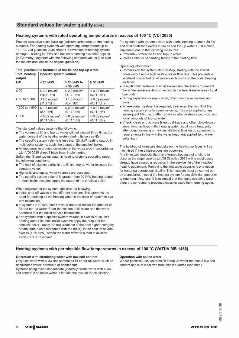
Heating systems with rated operating temperatures in excess of 100 °C (VDI 2035)Prevent excessive scale build-up (calcium carbonate) on the heatingsurfaces. For heating systems with operating temperatures up to100 °C, VDI guideline 2035 sheet 1 "Prevention of heating systemdamage – scaling in DHW and hot water heating systems" applies[in Germany], together with the following standard values (see alsothe full explanations in the original guideline).
Total permissible hardness of the fill and top-up waterTotal heatingoutput
Specific system volume
kW < 20 l/kW ≥ 20 l/kW to< 50 l/kW
≥ 50 l/kW
≤ 50 ≤ 3.0 mol/m3
(16.8 °dH)≤ 2.0 mol/m3
(11.2 °dH)< 0.02 mol/m3
(0.11 °dH)> 50 to ≤ 200 ≤ 2.0 mol/m3
(11.2 °dH)≤ 1.5 mol/m3
(8.4 °dH)< 0.02 mol/m3
(0.11 °dH)> 200 to ≤ 600 ≤ 1.5 mol/m3
(8.4 °dH)≤ 0.02 mol/m3
(0.11 °dH)< 0.02 mol/m3
(0.11 °dH)> 600 < 0.02 mol/m3
(0.11 °dH)< 0.02 mol/m3
(0.11 °dH)< 0.02 mol/m3
(0.11 °dH)
The standard values assume the following:■ The volume of fill and top-up water will not exceed three times the
water content of the heating system during its service life.■ The specific system volume is less than 20 l/kW heating output. In
multi boiler systems, apply the output of the smallest boiler.■ All measures to prevent corrosion on the water side in accordance
with VDI 2035 sheet 2 have been implemented.Soften the fill and top-up water in heating systems operating underthe following conditions:■ The total of alkaline earths in the fill and top-up water exceeds the
standard value.■ Higher fill and top-up water volumes are expected.■ The specific system volume is greater than 20 l/kW heating output.
In multi boiler systems, apply the output of the smallest boiler.
When engineering the system, observe the following:■ Install shut-off valves in the different sections. This prevents the
need for draining all the heating water in the case of repairs or sys-tem expansion.
■ In systems > 50 kW, install a water meter to record the amount offill and top-up water. Enter the volume of fill water and the waterhardness into the boiler service instructions.
■ For systems with a specific system volume in excess of 20 l/kWheating output (in multi boiler systems apply the output of thesmallest boiler), apply the requirements of the next higher categoryof total output (in accordance with the table). In the case of severeexcess (> 50 l/kW), soften the water down to a total of alkalineearths of ≤ 0.02 mol/m3
For systems with system boilers with a total heating output < 50 kWand total of alkaline earths in the fill and top-up water > 3.0 mol/m3,implement one of the following measures:■ Preferably soften the fill and top-up water.■ Install a filter or separating facility in the heating flow.
Operating information:■ Commission the system step by step, starting with the lowest
boiler output and a high heating water flow rate. This prevents alocalised concentration of limescale deposits on the boiler heatingsurfaces.
■ In multi boiler systems, start all boilers simultaneously to preventthe entire limescale deposit settling in the heat transfer area of justone boiler.
■ During expansion or repair work, only drain the necessary sec-tions.
■ Where water treatment is required, treat even the first fill of theheating system prior to commissioning. This also applies to anysubsequent filling, e.g. after repairs or after system expansion, andfor all amounts of top-up water.
■ Check, clean and activate filters, dirt traps and other blow-down orseparating facilities in the heating water circuit more frequentlyafter commissioning or new installations; later on do so subject torequirements in line with the water treatment applied (e.g. watersoftening).
The build-up of limescale deposits on the heating surfaces will beminimised if these instructions are observed.Any limescale deposits that have formed because of a failure toobserve the requirements to VDI Directive 2035 will in most casesalready have caused a reduction in the service life of the installedheating equipment. Removing the limescale deposits is one optionfor restoring operational viability. This measure must be carried outby a specialist. Inspect the heating system for possible damage priorto returning it into use. It is essential that the faulty operating param-eters are corrected to prevent excessive scale from forming again.
Heating systems with permissible flow temperatures in excess of 100 °C (VdTÜV MB 1466)
Operation with circulating water with low salt contentOnly use water with a low salt content as fill or top-up water, such asdesalinated water, permeate or condensate.Systems using mixed condensate generally create water with a lowsalt content if no boiler water is fed into the system for alkalisation.
Operation with saline waterWhere possible, use water as fill or top-up water that has a low saltcontent and is at least free from alkaline earths (softened).
Standard values for water quality (cont.)
8 VIESMANN VITOPLEX 100
5822
518
GB
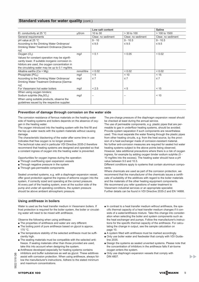
Low salt content SalineEl. conductivity at 25 °C μS/cm 10 to 30 > 30 to 100 > 100 to 1500General requirements Clear, no sediment Clear, no sediment Clear, no sedimentpH value at 25 °C 9 - 10 9 - 10.5 9 - 10.5According to the Drinking Water Ordinance/Drinking Water Treatment Ordinance [Germa-ny]
≤ 9.5 ≤ 9.5 ≤ 9.5
Oxygen (O2)Values for constant operation may be signifi-cantly lower. If suitable inorganic corrosion in-hibitors are used, the oxygen concentration inthe circulating water may be up to 0.1 mg/litre.
mg/l < 0.1 < 0.05 < 0.02
Alkaline earths (Ca + Mg) mmol/litre < 0.02 < 0.02 < 0.02Phosphate (PO4) mg/l < 5 < 10 < 15According to the Drinking Water Ordinance/Drinking Water Treatment Ordinance [Germa-ny]
mg/l ≤ 7 ≤ 7 ≤ 7
For Viessmann hot water boilers mg/l < 2.5 < 5 < 15When using oxygen binders: Sodium sulphite (Na2SO3)When using suitable products, observe theguidelines issued by the respective supplier.
mg/l – – < 10
Prevention of damage through corrosion on the water sideThe corrosion resistance of ferrous materials on the heating waterside of heating systems and boilers depends on the absence of oxy-gen in the heating water.The oxygen introduced into the heating system with the first fill andthe top-up water reacts with the system materials without causingdamage.The characteristic blackening of the water after some time in useindicates that free oxygen is no longer present.The technical rules and in particular VDI Directive 2035-2 thereforerecommend that heating systems are designed and operated so thata constant ingress of oxygen into the heating water is prevented.
Opportunities for oxygen ingress during the operation:■ Through overflowing open expansion vessels■ Through negative pressure in the system■ Through gas-permeable components
Sealed unvented systems, e.g. with a diaphragm expansion vessel,offer good protection against the ingress of airborne oxygen into thesystem, if correctly sized and operating at the correct pressure.At every part of the heating system, even at the suction side of thepump and under all operating conditions, the system pressureshould be above ambient atmospheric pressure.
The pre-charge pressure of the diaphragm expansion vessel shouldbe checked at least during the annual service.The use of permeable components, e.g. plastic pipes that are per-meable to gas in underfloor heating systems, should be avoided.Provide system separation if such components are neverthelessused. This must separate the water flowing through the plastic pipesfrom other heating circuits, e.g. from the heat source, by the provi-sion of a heat exchanger made of corrosion-resistant material.No further anti-corrosion measures are required for sealed hot waterheating systems subject to the above points being observed.However, take additional precautions where there is a risk of oxygeningress, for example by adding oxygen binder sodium sulphite (5 -10 mg/litre into the excess). The heating water should have a pHvalue between 9.0 and 10.5.Different conditions apply to systems that contain aluminium compo-nents.Where chemicals are used as part of the corrosion protection, werecommend that the manufacturer of the chemicals issues a certifi-cate of suitability of the additives with regard to the boiler materialsand the materials of the other heating equipment components.We recommend you refer questions of water treatment toViessmann industrial services or an appropriate specialist.Further details can be found in VDI Directive 2035-2 and EN 14868.
Using antifreeze in boilersWater is used as the heat transfer medium in Viessmann boilers. Iffrost protection is required for the boiler system, the boiler or circulat-ing water will need to be mixed with antifreeze.
Observe the following when using antifreeze:■ The properties of antifreeze and water are very different.■ The boiling point of pure antifreeze based on glycol is approx.
170 °C.■ The temperature stability of the selected antifreeze must be suffi-
ciently high.■ The sealing materials must be compatible with the selected anti-
freeze. If sealing materials other than those provided are used,take this into account when designing the system.
■ Antifreeze developed especially for heating systems containsinhibitors and buffer substances as well as glycol. These additivesassist with corrosion protection. When using antifreeze, always fol-low the manufacturer's instructions. Adhere to the stated minimumand maximum concentrations.
■ In contrast to a heat transfer medium without antifreeze, the spe-cific thermal capacity of a heat transfer medium changes if it con-sists of a water/antifreeze mixture. Take this change into consider-ation when selecting the boiler and system components such asthe heat exchanger and pumps. Follow the manufacturer's instruc-tions for the specific thermal capacity of the antifreeze. For calcu-lating the change in output, see the sample calculation onpage 10.
■ A system filled with antifreeze must be marked accordingly.■ Only use boiler water and feedwater that comply with VDI Guide-
line 2035.■ Design the systems as sealed unvented systems. Please note that
the concentration of inhibitors in the antifreeze falls if air-borneoxygen enters the system.
■ Only use diaphragm expansion vessels that comply withDIN 4807.
Standard values for water quality (cont.)
VITOPLEX 100 VIESMANN 9
5822
518
GB
■ Only use metal hoses or hoses with low permeability to oxygen asflexible connection elements.
■ The use of zinc-plated heat exchangers, vessels or pipes is notpermissible on the primary side of the systems. Zinc can be dis-solved by glycol/water mixtures.
The different properties of glycol and water may result in a reduction of boiler output. See the following sample calculation.
Sample calculation: Change in boiler output when operating with antifreezeTarget Maximum boiler output when using antifreeze ²K glycol
Given Boiler output ²K = 2 MW Antifreeze Tyfocor Spec. thermal capacity 3.78 kJ/kgK at 80 °C Mixing ratio Tyfocor/water 40/60
Calculation:
µ = ² =2000 kW kg K•3600 s
= 86,000kg
≙ 86 t/h c • Δt 4.187 kWs• 20 K •1h h
This results in the following:
´ ≈ 86 m3/h
²K glycol = µ • c • Δt = 86,000 kg • 3.78 kJ • 20 K • 1 hh h 3600 s
²K glycol = 1.8 MW
Result:If 40 % of the antifreeze given above is used in the heating network, the boiler output will be reduced by 10 %. The specific thermal capacitydepends on the mixing ratio and the temperature. Individual sizing is therefore necessary.
Design/engineering information
Mounting a suitable burnerThe burner must be suitable for the relevant rated heating outputand the pressure drop on the hot gas side of the boiler (see burnermanufacturer's specification).The material of the burner head must be suitable for operating tem-peratures of at least 500 °C.
Pressure-jet oil burnerThe burner must be tested and designated to EN 267.
Pressure-jet gas burnerThe burner must be tested to EN 676 and be identified with the CEdesignation in accordance with Directive 90/396/EEC.
Burner adjustmentAdjust the oil or gas throughput of the burner to suit the rated boilerheating output.
Permissible flow temperaturesHot water boilers for permissible flow temperatures (= safety temper-atures)
■ Up to 110 °CCE designation:CE-0085 compliant with the Gas Appliances Directive
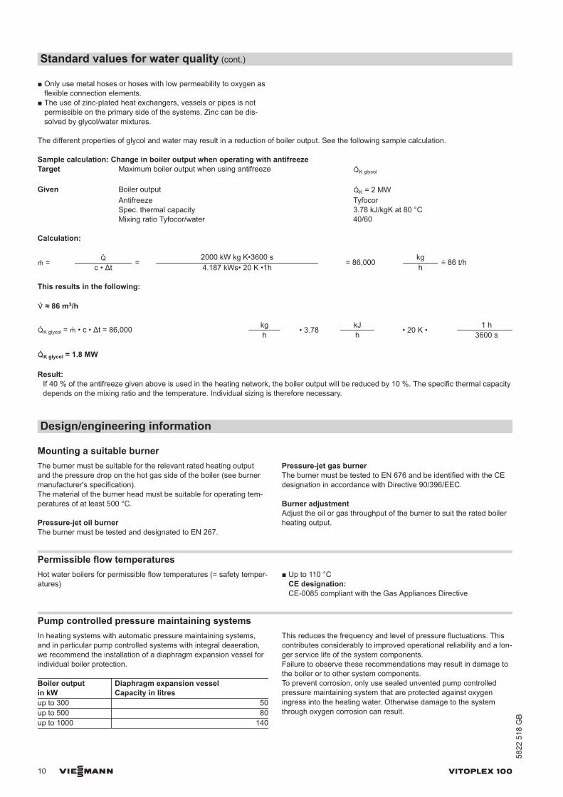
Pump controlled pressure maintaining systemsIn heating systems with automatic pressure maintaining systems,and in particular pump controlled systems with integral deaeration,we recommend the installation of a diaphragm expansion vessel forindividual boiler protection.
Boiler outputin kW
Diaphragm expansion vesselCapacity in litres
up to 300 50up to 500 80up to 1000 140
This reduces the frequency and level of pressure fluctuations. Thiscontributes considerably to improved operational reliability and a lon-ger service life of the system components.Failure to observe these recommendations may result in damage tothe boiler or to other system components.To prevent corrosion, only use sealed unvented pump controlledpressure maintaining system that are protected against oxygeningress into the heating water. Otherwise damage to the systemthrough oxygen corrosion can result.
Standard values for water quality (cont.)
10 VIESMANN VITOPLEX 100
5822
518
GB
Pump controlled pressure maintaining systems with atmosphericdeaeration through cyclical pressure release effect a central post-ventilation of the heating system. They do not provide oxygenremoval in the sense of corrosion protection as described inVDI 2035 Part 2.
Intended use
The appliance is only intended to be installed and operated in sealedunvented heating systems that comply with EN 12828, with dueattention paid to the associated installation, service and operatinginstructions as well as the details in the datasheet.It is only designed for the heating up of heating water.
Commercial or industrial usage for a purpose other than the heatingup of heating water shall be deemed inappropriate.
Intended use presupposes that a fixed installation in conjunction withpermissible components designed for this purpose has been carriedout.
Every other use will be deemed to be inappropriate. Any resultinglosses are excluded from the manufacturer's liability.
Any usage beyond this must be approved by the manufacturer forthe individual case.
Intended use also includes the adherence to maintenance andinspection intervals.
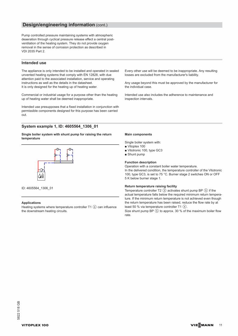
System example 1, ID: 4605564_1306_01
Single boiler system with shunt pump for raising the returntemperature
ID: 4605564_1306_01
ApplicationsHeating systems where temperature controller T1 4 can influencethe downstream heating circuits.
Main components
Single boiler system with:■ Vitoplex 100■ Vitotronic 100, type GC3■ Shunt pump
Function descriptionOperation with a constant boiler water temperature.In the delivered condition, the temperature controller of the Vitotronic100, type GC3, is set to 75 °C. Burner stage 2 switches ON or OFF5 K below burner stage 1.
Return temperature raising facilityTemperature controller T2 3 activates shunt pump BP 5 if theactual temperature falls below the required minimum return tempera-ture. If the minimum return temperature is not achieved even thoughthe return temperature has been raised, reduce the flow rate by atleast 50 % via temperature controller T1 4.Size shunt pump BP 5 to approx. 30 % of the maximum boiler flowrate.
Design/engineering information (cont.)
VITOPLEX 100 VIESMANN 11
5822
518
GB
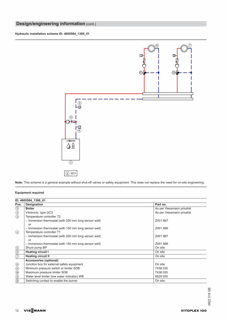
Hydraulic installation scheme ID: 4605564_1306_01
6 7
1
4
2
5
3
GC3
Note: This scheme is a general example without shut-off valves or safety equipment. This does not replace the need for on-site engineering.
Equipment required
ID: 4605564_1306_01Pos. Designation Part no.1 Boiler As per Viessmann pricelist2 Vitotronic, type GC3 As per Viessmann pricelist3 Temperature controller T2 – Immersion thermostat (with 200 mm long sensor well)
orZ001 887
– Immersion thermostat (with 150 mm long sensor well) Z001 8884 Temperature controller T1 – Immersion thermostat (with 200 mm long sensor well)
orZ001 887
– Immersion thermostat (with 150 mm long sensor well) Z001 8885 Shunt pump BP On site6 Heating circuit I On site7 Heating circuit II On site Accessories (optional) 8 Junction box for external safety equipment On site9 Minimum pressure switch or limiter SDB 7438 030qP Maximum pressure limiter SDB 7438 025qQ Water level limiter (low water indicator) WB 9529 050qW Switching contact to enable the burner On site
Design/engineering information (cont.)
12 VIESMANN VITOPLEX 100
5822
518
GB
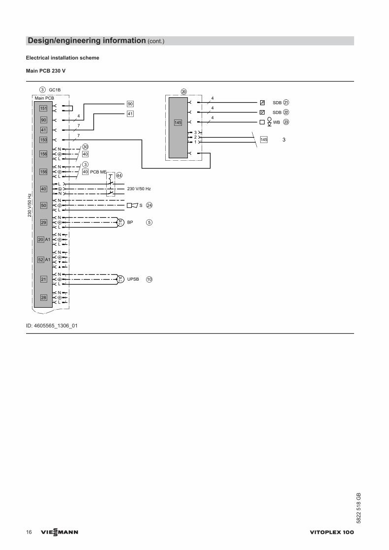
Electrical installation scheme
Main PCB 230 V
18
16
2 GC3
230
V/5
0 H
z
L
N
17
15
1314
1211
10987
6
45
3
12
N
L
T1T2
T8T7T6
230 V/50 Hz
41
qW
90
N
9 qP qQ
ID: 4605564_1306_01
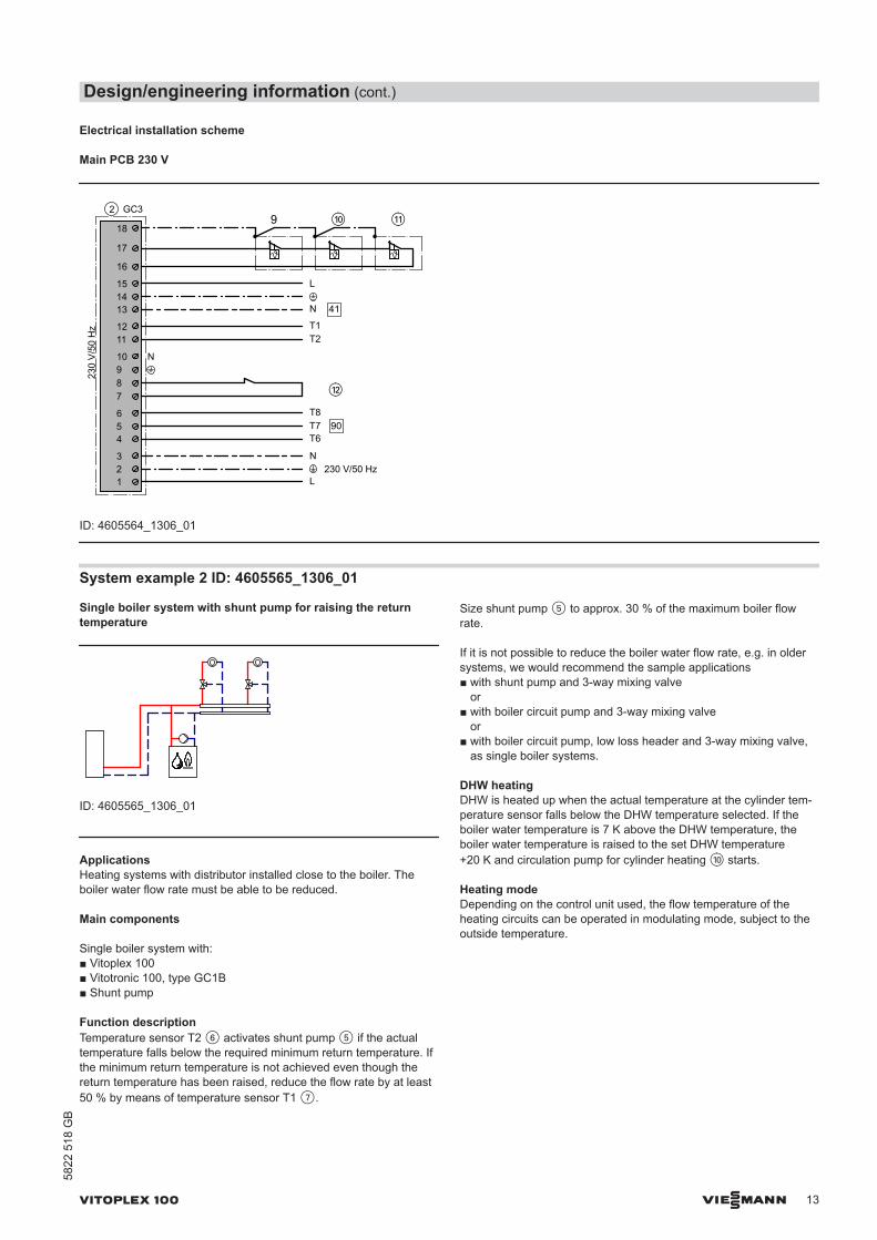
System example 2 ID: 4605565_1306_01
Single boiler system with shunt pump for raising the returntemperature
ID: 4605565_1306_01
ApplicationsHeating systems with distributor installed close to the boiler. Theboiler water flow rate must be able to be reduced.
Main components
Single boiler system with:■ Vitoplex 100■ Vitotronic 100, type GC1B■ Shunt pump
Function descriptionTemperature sensor T2 6 activates shunt pump 5 if the actualtemperature falls below the required minimum return temperature. Ifthe minimum return temperature is not achieved even though thereturn temperature has been raised, reduce the flow rate by at least50 % by means of temperature sensor T1 7.
Size shunt pump 5 to approx. 30 % of the maximum boiler flowrate.
If it is not possible to reduce the boiler water flow rate, e.g. in oldersystems, we would recommend the sample applications■ with shunt pump and 3-way mixing valve
or■ with boiler circuit pump and 3-way mixing valve
or■ with boiler circuit pump, low loss header and 3-way mixing valve,
as single boiler systems.
DHW heatingDHW is heated up when the actual temperature at the cylinder tem-perature sensor falls below the DHW temperature selected. If theboiler water temperature is 7 K above the DHW temperature, theboiler water temperature is raised to the set DHW temperature+20 K and circulation pump for cylinder heating qP starts.
Heating modeDepending on the control unit used, the flow temperature of theheating circuits can be operated in modulating mode, subject to theoutside temperature.
Design/engineering information (cont.)
VITOPLEX 100 VIESMANN 13
5822
518
GB
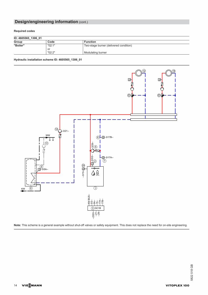
Required codes
ID: 4605565_1306_01Group Code Function"Boiler" "02:1"
or "02:2"
Two-stage burner (delivered condition)
Modulating burner
Hydraulic installation scheme ID: 4605565_1306_01
KW
WW
--3/5A--
8
9
11
10--3/21--
72
1
25
--3/17A--
--3/
3/2-
-
--3/
15--
3
--23
0V--
--21
----
29--
--K
M B
US
----
3/2-
---
5A--
--15
----
17A
----
17B
--
--3/
29--
5
--3/17B--6
GC1B
12 16
Note: This scheme is a general example without shut-off valves or safety equipment. This does not replace the need for on-site engineering.
Design/engineering information (cont.)
14 VIESMANN VITOPLEX 100
5822
518
GB
Equipment required
ID: 4605565_1306_01Pos. Designation Part no.1 Boiler As per Viessmann pricelist2 Boiler water temperature sensor KTS Standard delivery pos. 33 Vitotronic, type GC1B Standard delivery pos. 15 Shunt pump BP On site6 Temperature sensor T2 – Contact temperature sensor
or7426 463
– Immersion temperature sensorSensor well R½ x 100Sensor well R½ x 150
7438 7027816 0357817 326
7 Temperature sensor T1 – Contact temperature sensor
or7426 463
– Immersion temperature sensorSensor well R½ x 100Sensor well R½ x 150
7438 7027816 0357817 326
rR ON/OFF switch On site8 DHW cylinder As per Viessmann pricelist9 Cylinder temperature sensor STS Standard delivery of Vitotronic 200
and 300or7438 702 for the Vitotronic 100
qP Circulation pump for cylinder heating UPSB As per Viessmann pricelistqQ DHW circulation pump ZP (controlled on site) As per Vitoset pricelistqW Heating circuit I On siteqZ Heating circuit II On site Accessories (optional) wP Plug-in adaptor for external safety equipment 7164 404wQ Minimum pressure switch or limiter SDB 7438 030wW Maximum pressure limiter SDB 7438 025wE Water level limiter (low water indicator) WB As per Viessmann pricelistwR Central fault message system S On sitewT Flue gas temperature sensor AGS 7452 531wI Contactor relay 7814 681ePeQ
eW
EA1 extension:1 analogue input (0 to 10 V)– Defaulting the set boiler water temperature3 digital inputs– External blocking with central fault message– Fault messages
7452 091
eReTeZ
External hook-ups– External demand– External changeover of stepped/modulating burners– External blocking
On site
rP KM BUS distributor, when there are several KM BUS subscribers 7415 028 KM BUS subscribers:
– EA1 extension– Vitocom 100, type GSM2
As per Viessmann pricelist
rQ LON communication module for communication with the following components:Vitotronic 200-H (for regulating additional heating circuits)
7172 173
rW Vitocom 100, type GSM2 Z011 396rE Vitocom 200, type LAN2 with communication module Z011 390rZ Vitocom 300, type LAN3 with LON communication module Z011 399
Design/engineering information (cont.)
VITOPLEX 100 VIESMANN 15
5822
518
GB
Electrical installation scheme
Main PCB 230 V
230
V/5
0 H
z
151
90
41
150
156
156
40
50
29
20 A1
52 A1
21
28
UPSB 10
90
414
7
3
230 V/50 Hz
S
7
24
BP 5
4044
30
40
PCB ME
Main PCB
3 GC1B
4
4
4
SDB
SDB
WB145
1
32 145 3
wQ
wW
wE
wP
N
L
L
N
L
N
L
N
L
N
N
L
N
L
N
L
N
M1~
M1~
P
P
ID: 4605565_1306_01
Design/engineering information (cont.)
16 VIESMANN VITOPLEX 100
5822
518
GB
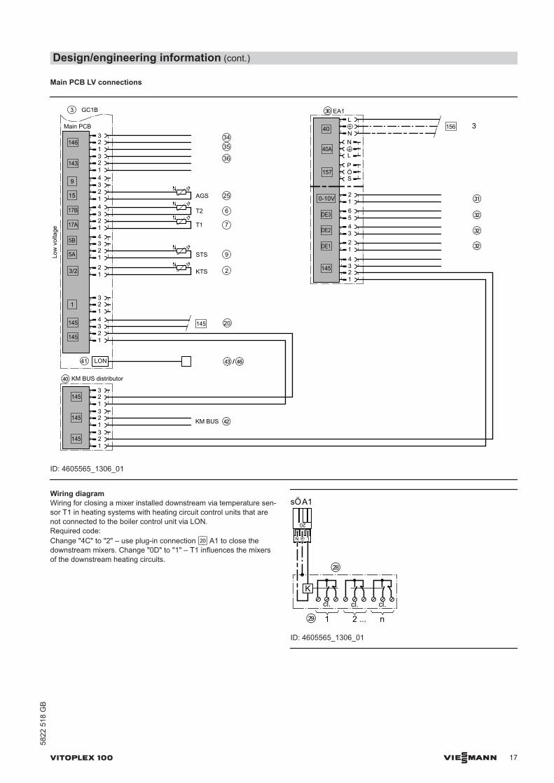
Main PCB LV connections
Low
vol
tage
STS
1
9
146
143
15 12
145
145
LON
AGS
20
349
T1 7
3/2 12
KTS
5B
5A
17B
17A
3
25
2
T2 6
145
1234
Main PCB
3435
36
41
GC1B
rE rZ
KM BUS145
145
KM BUS distributor
145
rW
rP
L
N40
40A
157
0-10V
145
12
56DE3
34DE2
DE1
EA1
34
eP
eQ
eW
eW
eW
3156
1
32
1
32
1
32
1234
1234
1
32
1
32
1
32
L
N
S
PÖ
12
12
ID: 4605565_1306_01
Wiring diagramWiring for closing a mixer installed downstream via temperature sen-sor T1 in heating systems with heating circuit control units that arenot connected to the boiler control unit via LON.Required code:Change "4C" to "2" – use plug-in connection sÖ A1 to close thedownstream mixers. Change "0D" to "1" – T1 influences the mixersof the downstream heating circuits.
20
A1
LN
K
1 2 ... n
sÖ
wI
wO
cl. cl. cl.
ID: 4605565_1306_01
Design/engineering information (cont.)
VITOPLEX 100 VIESMANN 17
5822
518
GB
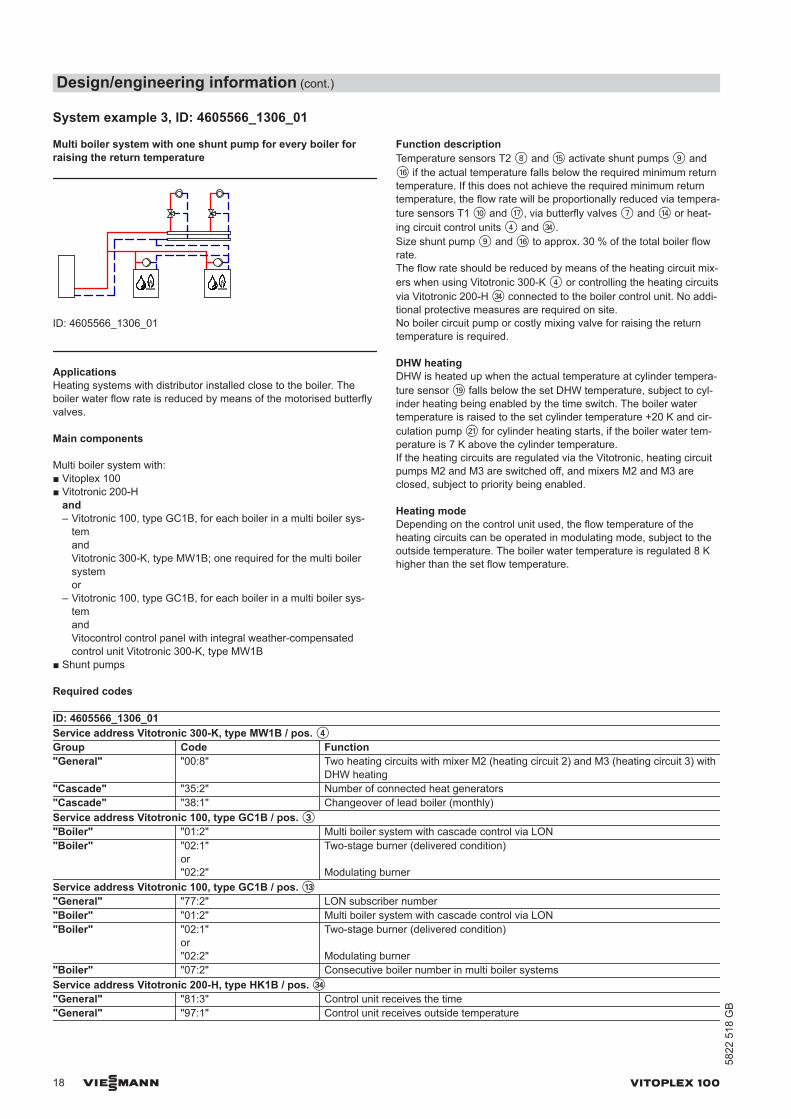
System example 3, ID: 4605566_1306_01
Multi boiler system with one shunt pump for every boiler forraising the return temperature
ID: 4605566_1306_01
ApplicationsHeating systems with distributor installed close to the boiler. Theboiler water flow rate is reduced by means of the motorised butterflyvalves.
Main components
Multi boiler system with:■ Vitoplex 100■ Vitotronic 200-H
and– Vitotronic 100, type GC1B, for each boiler in a multi boiler sys-
temandVitotronic 300-K, type MW1B; one required for the multi boilersystemor
– Vitotronic 100, type GC1B, for each boiler in a multi boiler sys-temandVitocontrol control panel with integral weather-compensatedcontrol unit Vitotronic 300-K, type MW1B
■ Shunt pumps
Function descriptionTemperature sensors T2 8 and qT activate shunt pumps 9 andqZ if the actual temperature falls below the required minimum returntemperature. If this does not achieve the required minimum returntemperature, the flow rate will be proportionally reduced via tempera-ture sensors T1 qP and qU, via butterfly valves 7 and qR or heat-ing circuit control units 4 and eR.Size shunt pump 9 and qZ to approx. 30 % of the total boiler flowrate.The flow rate should be reduced by means of the heating circuit mix-ers when using Vitotronic 300-K 4 or controlling the heating circuitsvia Vitotronic 200-H eR connected to the boiler control unit. No addi-tional protective measures are required on site.No boiler circuit pump or costly mixing valve for raising the returntemperature is required.
DHW heatingDHW is heated up when the actual temperature at cylinder tempera-ture sensor qO falls below the set DHW temperature, subject to cyl-inder heating being enabled by the time switch. The boiler watertemperature is raised to the set cylinder temperature +20 K and cir-culation pump wQ for cylinder heating starts, if the boiler water tem-perature is 7 K above the cylinder temperature.If the heating circuits are regulated via the Vitotronic, heating circuitpumps M2 and M3 are switched off, and mixers M2 and M3 areclosed, subject to priority being enabled.
Heating modeDepending on the control unit used, the flow temperature of theheating circuits can be operated in modulating mode, subject to theoutside temperature. The boiler water temperature is regulated 8 Khigher than the set flow temperature.
Required codes
ID: 4605566_1306_01Service address Vitotronic 300-K, type MW1B / pos. 4Group Code Function"General" "00:8" Two heating circuits with mixer M2 (heating circuit 2) and M3 (heating circuit 3) with
DHW heating"Cascade" "35:2" Number of connected heat generators"Cascade" "38:1" Changeover of lead boiler (monthly)Service address Vitotronic 100, type GC1B / pos. 3"Boiler" "01:2" Multi boiler system with cascade control via LON"Boiler" "02:1"
or "02:2"
Two-stage burner (delivered condition)
Modulating burnerService address Vitotronic 100, type GC1B / pos. qE"General" "77:2" LON subscriber number"Boiler" "01:2" Multi boiler system with cascade control via LON"Boiler" "02:1"
or "02:2"
Two-stage burner (delivered condition)
Modulating burner"Boiler" "07:2" Consecutive boiler number in multi boiler systemsService address Vitotronic 200-H, type HK1B / pos. eR"General" "81:3" Control unit receives the time"General" "97:1" Control unit receives outside temperature
Design/engineering information (cont.)
18 VIESMANN VITOPLEX 100
5822
518
GB
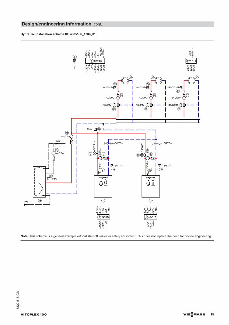
Hydraulic installation scheme ID: 4605566_1306_01
KW
WW
--4/5A--
18
19
20
34
22
23
24
25
26
27
28
29
30
31
32
33
--4/2M2--
--4/20M2--
--4/52M2--
--4/2M3--
--4/20M3--
-34/3/2M1-
-34/20M1-
-34/52M1-
--23
0V--
--52
M1-
---
20M
1--
--3/
2M1-
-
21--4/21--
--4/28--
102 1712
11
5
--3/17A--
--3/
3/2-
-
--4/
1--
--13/17A--
--13
/3/2
--
--LO
N--
4
--23
0V--
--21
----
28--
--52
M2-
---
20M
2--
--52
M3-
---
20M
3--
--2M
3--
--2M
2--
--5A
----
3/2-
---
1--
--K
M-B
us--
--LO
N--
13
--23
0V--
--52
A1-
-
--LO
N--
--LO
N--
--17
A--
--3/
2--
--4/3/2-- 6
--3/
52A
1--
--13
/52A
1--
7 14
--4/52M3--
--3/
29--
9
--3/17B--8
--29
--
--13/17B--15
--17
B--
--13
/29-
-
16
GC1B
1
3
--23
0V--
--52
A1-
-
--LO
N--
--LO
N--
--17
A--
--3/
2--
--29
----
17B
--
GC1B
HK1BMW1B
Note: This scheme is a general example without shut-off valves or safety equipment. This does not replace the need for on-site engineering.
Design/engineering information (cont.)
VITOPLEX 100 VIESMANN 19
5822
518
GB
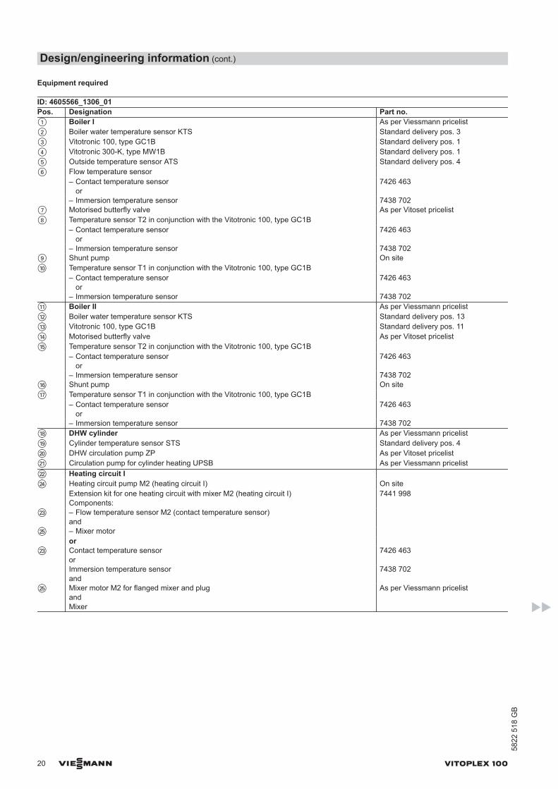
Equipment required
ID: 4605566_1306_01Pos. Designation Part no.1 Boiler I As per Viessmann pricelist2 Boiler water temperature sensor KTS Standard delivery pos. 33 Vitotronic 100, type GC1B Standard delivery pos. 14 Vitotronic 300-K, type MW1B Standard delivery pos. 15 Outside temperature sensor ATS Standard delivery pos. 46 Flow temperature sensor – Contact temperature sensor
or7426 463
– Immersion temperature sensor 7438 7027 Motorised butterfly valve As per Vitoset pricelist8 Temperature sensor T2 in conjunction with the Vitotronic 100, type GC1B – Contact temperature sensor
or7426 463
– Immersion temperature sensor 7438 7029 Shunt pump On siteqP Temperature sensor T1 in conjunction with the Vitotronic 100, type GC1B – Contact temperature sensor
or7426 463
– Immersion temperature sensor 7438 702qQ Boiler II As per Viessmann pricelistqW Boiler water temperature sensor KTS Standard delivery pos. 13qE Vitotronic 100, type GC1B Standard delivery pos. 11qR Motorised butterfly valve As per Vitoset pricelistqT Temperature sensor T2 in conjunction with the Vitotronic 100, type GC1B – Contact temperature sensor
or7426 463
– Immersion temperature sensor 7438 702qZ Shunt pump On siteqU Temperature sensor T1 in conjunction with the Vitotronic 100, type GC1B – Contact temperature sensor
or7426 463
– Immersion temperature sensor 7438 702qI DHW cylinder As per Viessmann pricelistqO Cylinder temperature sensor STS Standard delivery pos. 4wP DHW circulation pump ZP As per Vitoset pricelistwQ Circulation pump for cylinder heating UPSB As per Viessmann pricelistwW Heating circuit I wR Heating circuit pump M2 (heating circuit I) On site Extension kit for one heating circuit with mixer M2 (heating circuit I)
Components:7441 998
wE – Flow temperature sensor M2 (contact temperature sensor)and
wT – Mixer motor or wE Contact temperature sensor
or7426 463
Immersion temperature sensor and
7438 702
wT Mixer motor M2 for flanged mixer and plugandMixer
As per Viessmann pricelist
Design/engineering information (cont.)
20 VIESMANN VITOPLEX 100
5822
518
GB
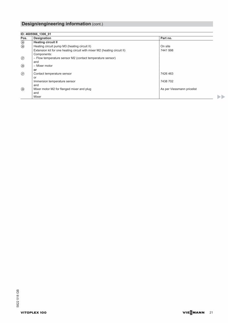
ID: 4605566_1306_01Pos. Designation Part no.wZ Heating circuit II wI Heating circuit pump M3 (heating circuit II) On site Extension kit for one heating circuit with mixer M2 (heating circuit II)
Components:7441 998
wU – Flow temperature sensor M2 (contact temperature sensor)and
wO – Mixer motor or wU Contact temperature sensor
or7426 463
Immersion temperature sensor and
7438 702
wO Mixer motor M2 for flanged mixer and plugandMixer
As per Viessmann pricelist
Design/engineering information (cont.)
VITOPLEX 100 VIESMANN 21
5822
518
GB
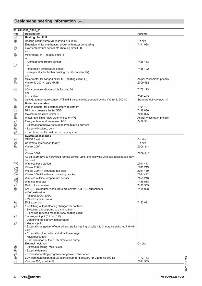
ID: 4605566_1306_01Pos. Designation Part no.eP Heating circuit III eW Heating circuit pump M1 (heating circuit III) On site
Extension kit for one heating circuit with mixer comprising 7441 998eQ Flow temperature sensor M1 (heating circuit III)
and
eE Mixer motor M1 (heating circuit III) or
eQ– Contact temperature sensor
or7426 463
– Immersion temperature sensor(see pricelist for further heating circuit control units)
7438 702
and eE Mixer motor for flanged mixer M1 (heating circuit III) As per Viessmann pricelisteR Vitotronic 200-H, type HK1B
andZ009 462
uP LON communication module for pos. 34and
7172 173
LON cable 7143 495eT Outside temperature sensor ATS (ATS value can be adopted by the Vitotronic 300-K) Standard delivery pos. 34 Boiler accessories eZ Plug-in adaptor for external safety equipment 7164 404eU Minimum pressure limiter SDB 7438 030eI Maximum pressure limiter SDB 7438 025eO Water level limiter (low water indicator) WB As per Viessmann pricelistrQ Flue gas temperature sensor AGS 7452 531zR - External changeover of stepped/modulating burners zI - External blocking, boiler zO - Start boiler as the last one in the sequence System accessories rP ON/OFF switch On siterO Central fault message facility On sitetP Vitotrol 200A
orZ008 341
Vitotrol 300A Z008 342 As an alternative to hardwired remote control units, the following wireless accessories may
be used.q-P Wireless base station Z011 413q-Q Vitotrol 200 RF Z011 219q-W Vitotrol 300 RF with table-top dock Z011 410q-E Vitotrol 300 RF with wall mounting bracket Z011 412q-R Wireless outside temperature sensor 7455 213q-T Wireless repeater 7456 538tQ Radio clock receiver 7450 563tE KM BUS distributor, when there are several KM BUS subscribers
– EA1 extension– Vitotrol 200A, 300A– Wireless base station
7415 028
zP EA1 extension 7452 091zQ 1 switching output (floating changeover contact)
- Switching a feed pump to a substation- Signalling reduced mode for one heating circuit
zW 1 analogue input (0 to – 10 V)- Defaulting the set flow temperature
zE 3 digital inputs- External changeover of operating state for heating circuits 1 to 3, may be switched individ-ually - External blocking with central fault message- Fault messages- Brief operation of the DHW circulation pump
External hook-ups On sitezT - External blocking, mixer close zZ - External demand zU - External operating program changeover, mixer open uP LON communication module (part of standard delivery for Vitotronic 300-K) 7172 173uQ Vitocom 300, type LAN3 Z011 555
Design/engineering information (cont.)
22 VIESMANN VITOPLEX 100
5822
518
GB
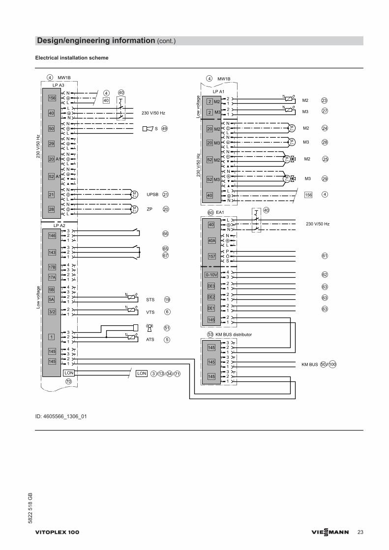
Electrical installation scheme
LP A2
1
146
143
145
145
LON
3/2 12
5B
5A
17B
17A 1234
Low
vol
tage
12 M3 27
1M2 232
2 M3
M2
LP A1
2
STS 19
VTS 6
5ATS
51
Low
vol
tage
ZP
230
V/5
0 H
z
4
20
156
40
50
29
20 A1
52 A1
21
28
UPSB 21
230 V/50 Hz
LP A3
S 49
4
40
4
M3 28
M2 25
M3 29
M2 2420
52
52
20 M3
M2
M3
M2
230
V/5
0 H
z40 4156
KM BUS
53
145
145
50
60
40
40A
157
0-10V 62
63
145
34
DE3
145
63DE2
63DE1
EA1
KM BUS distributor
61
70
230 V/50 Hz
40
65
66
67
40
100
MW1B MW1B
LON 3 13 34/ / 71/
1
32
1
32
1
32
1234
1234
L
N
L
N
L
N
L
N
N
L
N
L
NM1~
M1~
L
N
N
M1~
M1~
NM1~
L
N
M1~
1
32
L
N
S
PÖ
12
12
12
N
L
N
L
N
L
1
32
1
32
12
ID: 4605566_1306_01
Design/engineering information (cont.)
VITOPLEX 100 VIESMANN 23
5822
518
GB
230
V/5
0 H
z
3
151
90
41
150
156
156
40
50
29
20 A1
52 A1
21
28
LP A3
M1~ 14
364
4
4
SDB
SDB
WB145
7145
90
41
7
S
LP A1
Low
vol
tage T1 17
KTS 12
AGS
1
146
143
15 12
145
145
LON
3/2 12
5B
5A
17B
17A 1234
13
3 13
4
37
38
39
7
49
10
2
41
/
/
/
/
/
T2 158 /
BP 169 /
230 V/50 Hz
40
69
64
68
GC1B
36145
LON 4 3 13 34/ / /70
71/
L
N
L
N
L
N
L
N
N
L
N
L
N
L
N
1
32
P
P
1
32
1
32
1
32
1234
1234
M1~
N
L
ID: 4605566_1306_01
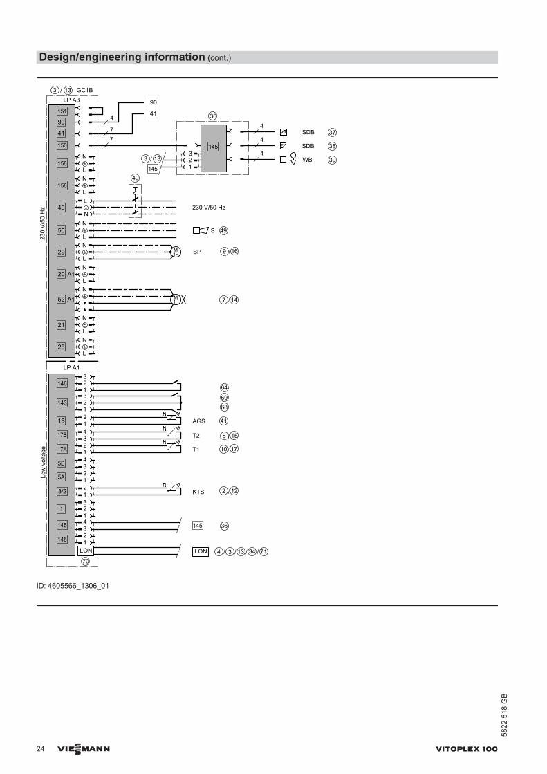
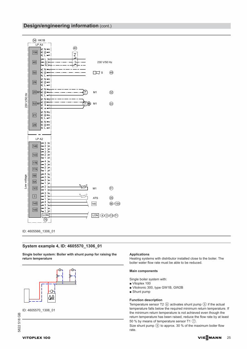
Design/engineering information (cont.)
24 VIESMANN VITOPLEX 100
5822
518
GB
230
V/5
0 H
z
34
156
40
50
29
20 M1
52 M1
21
28
LP A3
M1M1~ 33
S 49
LP A2
Low
vol
tage
M1 31
1
146
143
145
145
LON
3/2 12
5B
5A
17B
17A 1234
M1 32
230 V/50 Hz
40
35ATS
HK1B
4 3 13LON / / 71/70
145 tP q-P/
L
N
L
N
L
N
L
N
N
L
N
L
N
1
32
1
32
1
32
1234
1234
M1~
N
L
ID: 4605566_1306_01
System example 4, ID: 4605570_1306_01
Single boiler system: Boiler with shunt pump for raising thereturn temperature
ID: 4605570_1306_01
ApplicationsHeating systems with distributor installed close to the boiler. Theboiler water flow rate must be able to be reduced.
Main components
Single boiler system with:■ Vitoplex 100■ Vitotronic 300, type GW1B, GW2B■ Shunt pump
Function descriptionTemperature sensor T2 6 activates shunt pump 5 if the actualtemperature falls below the required minimum return temperature. Ifthe minimum return temperature is not achieved even though thereturn temperature has been raised, reduce the flow rate by at least50 % by means of temperature sensor T1 7.Size shunt pump 5 to approx. 30 % of the maximum boiler flowrate.
Design/engineering information (cont.)
VITOPLEX 100 VIESMANN 25
5822
518
GB
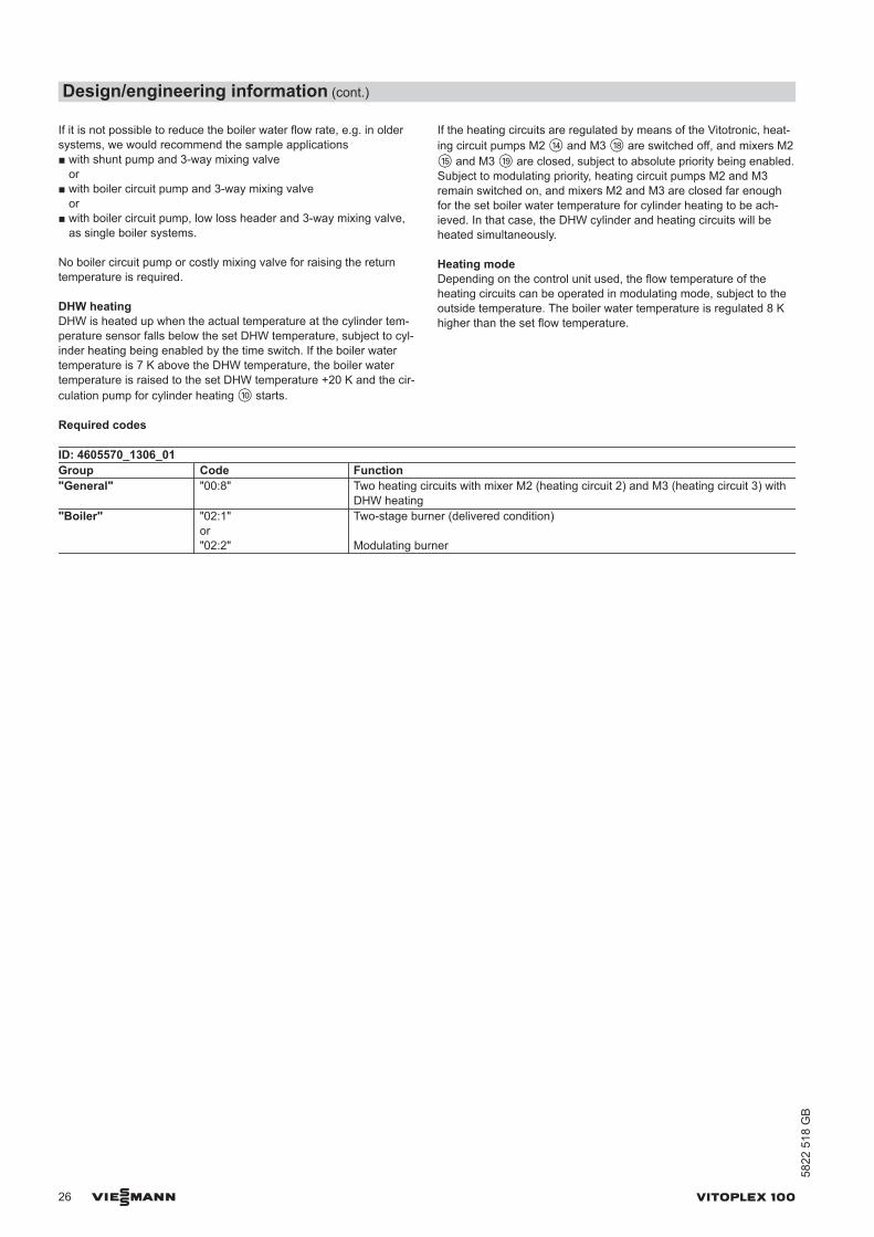
If it is not possible to reduce the boiler water flow rate, e.g. in oldersystems, we would recommend the sample applications■ with shunt pump and 3-way mixing valve
or■ with boiler circuit pump and 3-way mixing valve
or■ with boiler circuit pump, low loss header and 3-way mixing valve,
as single boiler systems.
No boiler circuit pump or costly mixing valve for raising the returntemperature is required.
DHW heatingDHW is heated up when the actual temperature at the cylinder tem-perature sensor falls below the set DHW temperature, subject to cyl-inder heating being enabled by the time switch. If the boiler watertemperature is 7 K above the DHW temperature, the boiler watertemperature is raised to the set DHW temperature +20 K and the cir-culation pump for cylinder heating qP starts.
If the heating circuits are regulated by means of the Vitotronic, heat-ing circuit pumps M2 qR and M3 qI are switched off, and mixers M2qT and M3 qO are closed, subject to absolute priority being enabled.Subject to modulating priority, heating circuit pumps M2 and M3remain switched on, and mixers M2 and M3 are closed far enoughfor the set boiler water temperature for cylinder heating to be ach-ieved. In that case, the DHW cylinder and heating circuits will beheated simultaneously.
Heating modeDepending on the control unit used, the flow temperature of theheating circuits can be operated in modulating mode, subject to theoutside temperature. The boiler water temperature is regulated 8 Khigher than the set flow temperature.
Required codes
ID: 4605570_1306_01Group Code Function"General" "00:8" Two heating circuits with mixer M2 (heating circuit 2) and M3 (heating circuit 3) with
DHW heating"Boiler" "02:1"
or "02:2"
Two-stage burner (delivered condition)
Modulating burner
Design/engineering information (cont.)
26 VIESMANN VITOPLEX 100
5822
518
GB
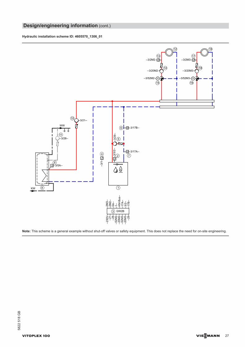
Hydraulic installation scheme ID: 4605570_1306_01
KW
WW
--3/5A--
8
9
11
12
13
14
15
16
17
18
19
--3/2M2--
--3/20M2--
--3/52M2--
--3/2M3--
--3/20M3--
10--3/21--
--3/28--
72
1
4--3/17A--
--3/
3/2-
-
--3/
1--
3
--23
0V--
--21
----
28--
--52
M2-
---
20M
2--
--52
M3-
---
20M
3--
--2M
3--
--2M
2--
--5A
----
1--
--K
M-B
us--
--3/52M3--
--3/
29--
5
--3/17B--6
--17
A--
--3/
2--
--17
B--
--29
--
GW2B
Note: This scheme is a general example without shut-off valves or safety equipment. This does not replace the need for on-site engineering.
Design/engineering information (cont.)
VITOPLEX 100 VIESMANN 27
5822
518
GB

Equipment required
ID: 4605570_1306_01Pos. Designation Part no.1 Boiler As per Viessmann pricelist2 Boiler water temperature sensor KTS Standard delivery pos. 33 Vitotronic, type GW1B or GW2B Standard delivery pos. 14 Outside temperature sensor ATS Standard delivery pos. 35 Shunt pump BP On site6 Temperature sensor T2 – Contact temperature sensor
or7426 463
– Immersion temperature sensorSensor well R½ x 100Sensor well R½ x 150
7438 7027816 0357817 326
7 Temperature sensor T1 – Contact temperature sensor
or7426 463
– Immersion temperature sensorSensor well R½ x 100Sensor well R½ x 150
7438 7027816 0357817 326
rR ON/OFF switch On site8 DHW cylinder As per Viessmann pricelist9 Cylinder temperature sensor STS Standard delivery of Vitotronic 200
and 300qP Circulation pump for cylinder heating UPSB As per Viessmann pricelistqQ DHW circulation pump ZP As per Vitoset pricelistqW Heating circuit I (only for Vitotronic 300, type GW2B) On siteqR Heating circuit pump M2 (heating circuit I) On site Extension kit for one heating circuit with mixer comprising 7441 998qE Flow temperature sensor M2 (heating circuit I)
and
qT Mixer motor M2 (heating circuit I) or – Immersion temperature sensor
Sensor well R½ x 100Sensor well R½ x 150(see pricelist for further heating circuit control units)
7438 7027816 0357817 326
and qT Mixer motor for flanged mixer M2 (heating circuit I) As per Viessmann pricelistqZ Heating circuit II (only for Vitotronic 300, type GW2B) On siteqI Heating circuit pump M3 (heating circuit II) On siteqU Flow temperature sensor M3 (heating circuit II)
and
qO Mixer motor M3 (heating circuit II) or qU – Contact temperature sensor
or7426 463
– Immersion temperature sensorSensor well R½ x 100Sensor well R½ x 150(see pricelist for further heating circuit control units)
7438 7027816 0357817 326
and qO Mixer motor for flanged mixer M3 (heating circuit II) As per Viessmann pricelist
Design/engineering information (cont.)
28 VIESMANN VITOPLEX 100
5822
518
GB

ID: 4605570_1306_01Pos. Designation Part no. Accessories (optional) wP Plug-in adaptor for external safety equipment 7164 404wQ Minimum pressure switch or limiter SDB 7438 030wW Maximum pressure limiter SDB 7438 025wE Water level limiter (low water indicator) WB As per Viessmann pricelistwR Central fault message system S On sitewT Flue gas temperature sensor AGS 7452 531wZ Vitotrol 200A
orZ008 341
Vitotrol 300A Z008 342 As an alternative to hardwired remote control units, the following wireless accessories may be
used.q-P Wireless base station Z011 413q-Q Vitotrol 200 RF Z011 219q-W Vitotrol 300 RF with table-top dock Z011 410q-E Vitotrol 300 RF with wall mounting bracket Z011 412q-R Wireless outside temperature sensor 7455 213q-T Wireless repeater 7456 538wU Radio clock receiver 7450 563wI Contactor relay 7814 681ePeQ
eW
eE
EA1 extension:1 analogue input (0 to 10 V)– Defaulting the set boiler water temperature3 digital inputs– External changeover of the operating status for heating circuits 1 to 3, may be switched in-
dividually (with weather-compensated control unit)– External blocking with central fault message– Fault messages– Brief operation of DHW circulation pump (with weather-compensated control unit)1 switching output (floating changeover contact)– Switching a feed pump to a substation– Signalling reduced mode for a heating circuit
7452 091
eReTeZeU
External hook-ups for weather-compensated control units– External demand– External changeover of stepped/modulating burners– External blocking, mixer close– External operating program changeover, mixer open
On site
rP KM BUS distributor, when there are several KM BUS subscribers 7415 028 KM BUS subscribers:
– EA1 extension– Vitotrol 200A, 300A– Wireless base station
As per Viessmann pricelist
rQ LON communication module for communication with the following components:Vitotronic 200-H (for regulating additional heating circuits)
7172 173
rW Vitocom 100, type GSM2 Z011 396rE Vitocom 100, type LAN1 with communication module Z011 224rR Vitocom 200, type LAN2 with communication module Z011 390rZ Vitocom 300, type LAN3 with LON communication module Z011 399
Design/engineering information (cont.)
VITOPLEX 100 VIESMANN 29
5822
518
GB
Electrical installation scheme
Main PCB 230 V
ZP
230
V/ 5
0 H
z
11
151
90
41
150
156
156
40
50
29
20 A1
52 A1
21
28
UPSB 10
204
4
4
SDB
SDB
WB
90
414
7
145
3
3
230 V/ 50 Hz
S
721
22
23
24
BP 5
40
145
44
30
40
PCB ME
Main PCB
3 GW2B
N
L
L
N
L
N
L
N
L
N
N
L
N
L
NM1~
L
N
M1~
1
32
P
P
M1~
ID: 4605570_1306_01
Design/engineering information (cont.)
30 VIESMANN VITOPLEX 100
5822
518
GB
Main PCB LV connections
Low
vol
tage
STS
1
146
143
15 12
145
145
LON
AGS
349
T1
3/2 12
KTS
5B
5A
17B
17A
145
ATS
145
145
40
40A
157
0-10V
145
L
N
34
DE3
145
DE2
DE1
156
1234
Main PCB
EA1
KM BUS distributor
12
VTS M22 M2
12
VTS M32 M3
20 M2
20 M3
52 M2
52 M3
M2
M3
156
230
V/5
0 H
z
HKP M2
HCP M3
40
PCB ME
GW2B
KM BUS
/ /
/ /
T2
1
32
1
32
1
32
1
32
L
N
S
PÖ
12
12
12
1234
1234
L
N
L
N
N
N
M1~
M1~
M1~
M1~
N
L
12
1
32
1
32
2
3435
25
7
9
2
27
4
20
41 43 44
13
17
14
18
15
19
3
40
30
3
33
31
32
24 42 100
3637
46
32
32
6
ID: 4605570_1306_01
Wiring diagramWiring for closing a mixer installed downstream via temperature sen-sor T1 in heating systems with heating circuit control units that arenot connected to the boiler control unit via LON.Required code:Change "4C" to "2" – use plug-in connection sÖ A1 to close thedownstream mixers. Change "0D" to "1" – Therm-Control influencesthe mixers of the downstream heating circuits (delivered condition forthe Vitotronic 300).
Design/engineering information (cont.)
VITOPLEX 100 VIESMANN 31
5822
518
GB
20
A1
LN
K
1 2 ... n
sÖ
wI
wO
cl. cl. cl.
ID: 4605570_1306_01
Tested qualityCE designation according to current EC directives.
Design/engineering information (cont.)
32 VIESMANN VITOPLEX 100
5822
518
GB

VITOPLEX 100 VIESMANN 33
5822
518
GB

34 VIESMANN VITOPLEX 100
5822
518
GB
Subject to technical modifications.
Viessmann LimitedHortonwood 30, TelfordShropshire, TF1 7YP, GBTelephone: +44 1952 675000Fax: +44 1952 675040E-mail: [email protected]
Viessmann Werke GmbH&Co KGD-35107 AllendorfTelephone: +49 6452 70-0Fax: +49 6452 70-2780www.viessmann.com


![VIESMANN VITOPLEX 300 - Viessmann · Combustion chamber length mm 1700 1700 1930 1930 2530 2530 Weight boiler body kg 1650 1890 2560 2715 3545 4025 ... [to DIN] (for operation with](https://img.pdfslide.net/doc/110x75/5bc3831409d3f28a2b8be6c1/viesmann-vitoplex-300-viessmann-combustion-chamber-length-mm-1700-1700-1930.jpg)