Embed Size (px)
Citation preview
STANDARD OPERATING
PROCEDURES
Environmental
SOP BBS-PC-BU-701 Weed Control
SOP BBS-PC-BU-702 Noise monitoring and reporting
SOP BBS-PC-BU-703 Environmental Management of Storage areas
SOP BBS-PC-BU-705 Threatened plants
SOP BBS-PC-BU-706 Management of Spill Basins
SOP BBS-PC-BU-708 Monitoring of Road Kill (record daily, report
monthly)
SOP BBS-PC-BU-709 Monitoring Fauna structures
SOP BBS-PC-BU-711 Water Quality Monitoring (Year 1)
SOP BBS-PC-BU-712 Managing Acid Sulfate Soils
SOP BBS-PC-BU-713 Maintenance at Waterways
SOP BBS-PC-BU-714 Environmental Risk Assessment
SOP BBS-PC-BU-715 Groundwater Monitoring
APPENDIX 7
STANDARD OPERATING PROCEDURE SOP BBS-PC-BU-701
701
WEED CONTROL ENVIRONMENTAL
Revision No. Drafted Author Approved Date
1 13 March 2008 R Walker-Edwards
2 6 Oct 2008 R Walker-Edwards
3 7 Nov 2008 R Walker-Edwards
4 25 Nov 2008 R Walker-Edwards
PURPOSE
To provide guidance to the Leading Hand and maintenance personnel on managing weeds
and handling of the suitable herbicide.
SCOPE
This SOP covers the issues associated with choosing a weed management method, using a
recommended herbicide and lists the requirements of good application practice.
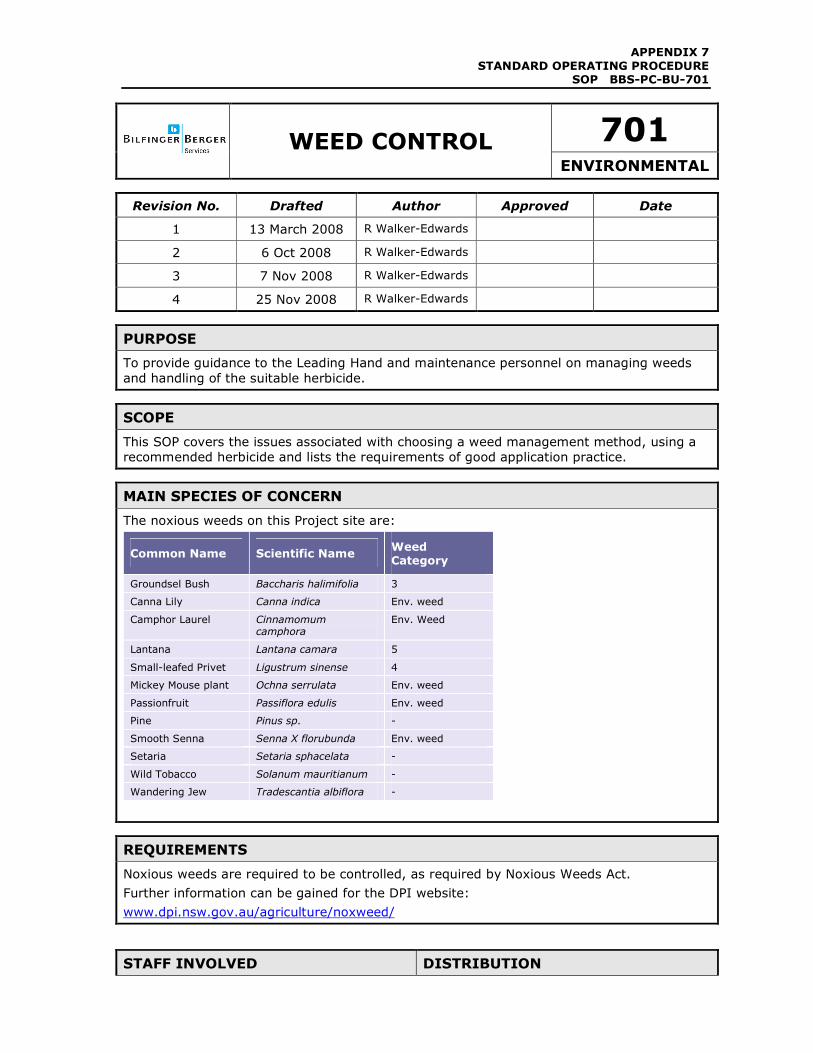
MAIN SPECIES OF CONCERN
The noxious weeds on this Project site are:
Common Name Scientific Name Weed
Category
Groundsel Bush Baccharis halimifolia 3
Canna Lily Canna indica Env. weed
Camphor Laurel Cinnamomum camphora
Env. Weed
Lantana Lantana camara 5
Small-leafed Privet Ligustrum sinense 4
Mickey Mouse plant Ochna serrulata Env. weed
Passionfruit Passiflora edulis Env. weed
Pine Pinus sp. -
Smooth Senna Senna X florubunda Env. weed
Setaria Setaria sphacelata -
Wild Tobacco Solanum mauritianum -
Wandering Jew Tradescantia albiflora -
REQUIREMENTS
Noxious weeds are required to be controlled, as required by Noxious Weeds Act.
Further information can be gained for the DPI website:
www.dpi.nsw.gov.au/agriculture/noxweed/
STAFF INVOLVED DISTRIBUTION
APPENDIX 7
STANDARD OPERATING PROCEDURE SOP BBS-PC-BU-701
Always
• Maintenance Manager
• Maintenance Supervisor
Possibly • MMS Representative
• QA, Env, OH&S Manager
• Leading Hand
• MMS Representative �
• Maintenance Manager �
• Maintenance Supervisor �
• Leading Hand �
• RTA �
• Sub-contractor/Consultant �
STEP 1 – Weed Management Planning
1. On an annual basis inspect the project site to examine and identify weed infestation.
2. Refer to the “Noxious and Environmental Weed Control Handbook 2004-2005”. (Copies
of this handbook can be downloaded for free from:
http://www.agric.nsw.gov.au/reader/weed-pubs/nox-weeds-splash.htm). The control
techniques for each weed species identified will be consistent with the practices outlined
in the handbook.
3. Weed control will be carried out to prevent the build up of invasive weeds in landscape
areas and to remove noxious weeds as they are identified within the project site. An
integrated weed management approach involving both targeted herbicide and non-
herbicide controls will be used.
4. There will be no weed control in adjacent areas, including Bongil Bongil National Park.
5. Weed control will no occur within the three translocation sites, this will be undertaken by
the ecologist in accordance with the Translocation Plan.
STEP 2 – Herbicide
1. In reference to the “Noxious and Environmental Weed Control Handbook 2004-2005”
and site conditions, determine if the use of herbicide is the preferred control measure.
2. If using herbicide, the recommended herbicide is ‘Roundup’ (glyphosate based).
3. Due to its short residual life, it is the safest product for people and the environment. It
works on a ‘systematic’ basis, i.e. if one sprays a leaf, it will kill the plant.
4. It must be mixed in accordance with the manufacturer’s instructions.
APPENDIX 7
STANDARD OPERATING PROCEDURE SOP BBS-PC-BU-701
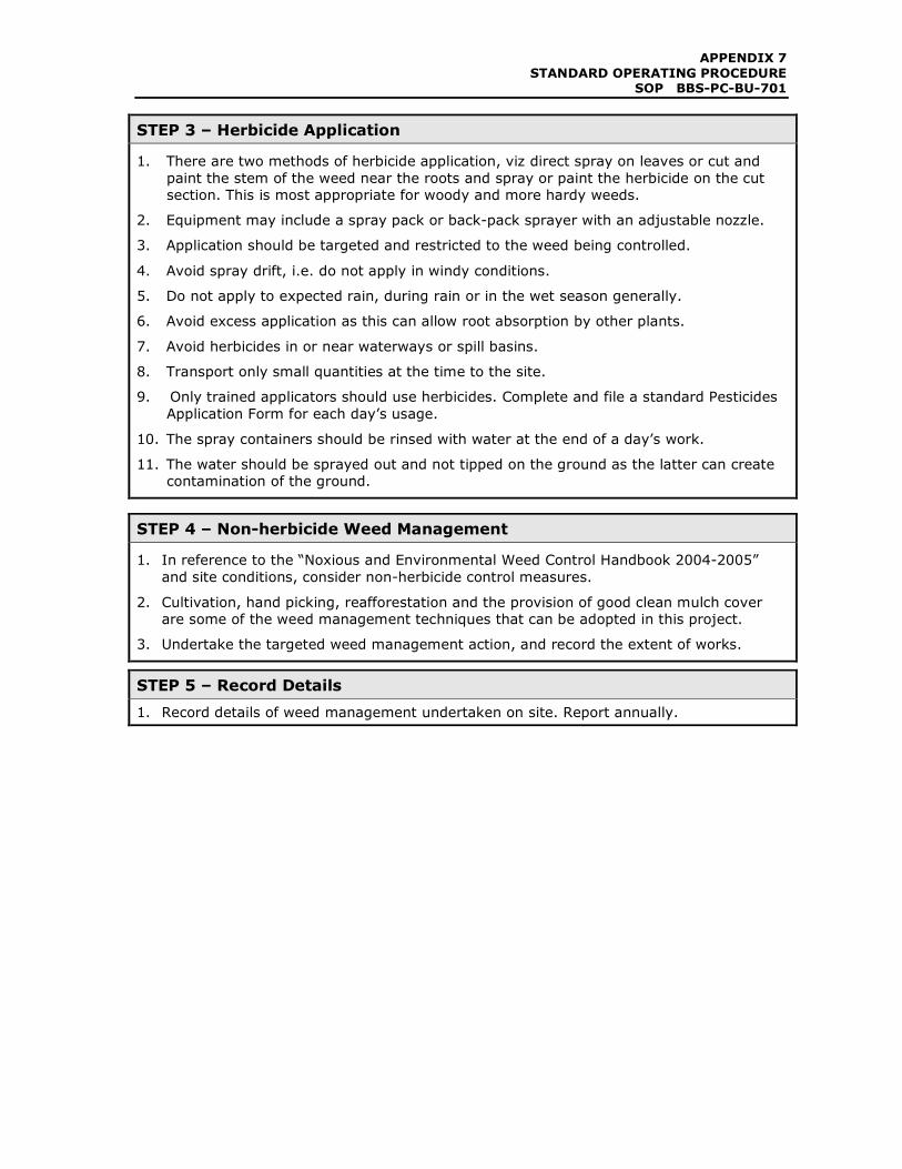
STEP 3 – Herbicide Application
1. There are two methods of herbicide application, viz direct spray on leaves or cut and
paint the stem of the weed near the roots and spray or paint the herbicide on the cut
section. This is most appropriate for woody and more hardy weeds.
2. Equipment may include a spray pack or back-pack sprayer with an adjustable nozzle.
3. Application should be targeted and restricted to the weed being controlled.
4. Avoid spray drift, i.e. do not apply in windy conditions.
5. Do not apply to expected rain, during rain or in the wet season generally.
6. Avoid excess application as this can allow root absorption by other plants.
7. Avoid herbicides in or near waterways or spill basins.
8. Transport only small quantities at the time to the site.
9. Only trained applicators should use herbicides. Complete and file a standard Pesticides
Application Form for each day’s usage.
10. The spray containers should be rinsed with water at the end of a day’s work.
11. The water should be sprayed out and not tipped on the ground as the latter can create
contamination of the ground.
STEP 4 – Non-herbicide Weed Management
1. In reference to the “Noxious and Environmental Weed Control Handbook 2004-2005”
and site conditions, consider non-herbicide control measures.
2. Cultivation, hand picking, reafforestation and the provision of good clean mulch cover
are some of the weed management techniques that can be adopted in this project.
3. Undertake the targeted weed management action, and record the extent of works.
STEP 5 – Record Details
1. Record details of weed management undertaken on site. Report annually.
APPENDIX 7
STANDARD OPERATING PROCEDURE SOP BBS-PC-BU-701
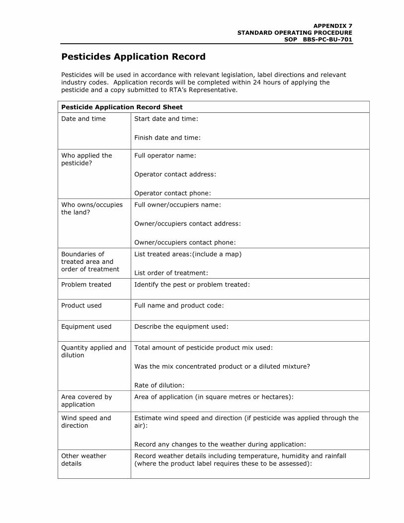
Pesticides Application Record Pesticides will be used in accordance with relevant legislation, label directions and relevant
industry codes. Application records will be completed within 24 hours of applying the
pesticide and a copy submitted to RTA’s Representative.
Pesticide Application Record Sheet
Date and time Start date and time:
Finish date and time:
Who applied the
pesticide?
Full operator name:
Operator contact address:
Operator contact phone:
Who owns/occupies
the land?
Full owner/occupiers name:
Owner/occupiers contact address:
Owner/occupiers contact phone:
Boundaries of
treated area and
order of treatment
List treated areas:(include a map)
List order of treatment:
Problem treated Identify the pest or problem treated:
Product used Full name and product code:
Equipment used Describe the equipment used:
Quantity applied and
dilution
Total amount of pesticide product mix used:
Was the mix concentrated product or a diluted mixture?
Rate of dilution:
Area covered by
application
Area of application (in square metres or hectares):
Wind speed and
direction
Estimate wind speed and direction (if pesticide was applied through the
air):
Record any changes to the weather during application:
Other weather
details
Record weather details including temperature, humidity and rainfall
(where the product label requires these to be assessed):
APPENDIX 7
STANDARD OPERATING PROCEDURE SOP BBS-PC-BU-701
The Record Sheet does not need to be completed where the following are satisfied:
• the pesticide is only applied by hand or by using hand held equipment; AND
• if applied outdoors on any one occasion is not more than 5 litres/5 kilograms of
concentrated product or 20 litres/20kilograms of the ready to use product, or if
applied indoors in quantities of no more than 1 litre/1kilogram of concentrated
product or 5 litres/5kilograms of the ready to use product.
All personnel managing and using pesticides will be given appropriate training prior to
commencing work. Only pesticides registered for use near water may be used near water.
Application will be avoided:
• On hot days when plants are stressed;
• After seed has set;
• Within 24 hours of rain or when rain is imminent;
• When wind will cause drift into non-target areas.
APPENDIX 7
STANDARD OPERATING PROCEDURE SOP BBS-PC-BU-702
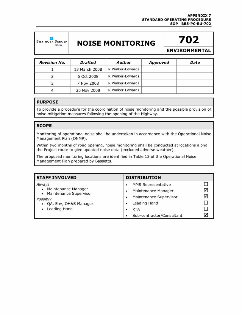
702
NOISE MONITORING ENVIRONMENTAL
Revision No. Drafted Author Approved Date
1 13 March 2008 R Walker-Edwards
2 6 Oct 2008 R Walker-Edwards
3 7 Nov 2008 R Walker-Edwards
4 25 Nov 2008 R Walker-Edwards
PURPOSE
To provide a procedure for the coordination of noise monitoring and the possible provision of
noise mitigation measures following the opening of the Highway.
SCOPE
Monitoring of operational noise shall be undertaken in accordance with the Operational Noise
Management Plan (ONMP).
Within two months of road opening, noise monitoring shall be conducted at locations along
the Project route to give updated noise data (excluded adverse weather).
The proposed monitoring locations are identified in Table 13 of the Operational Noise
Management Plan prepared by Bassetts.
STAFF INVOLVED DISTRIBUTION
Always
• Maintenance Manager
• Maintenance Supervisor
Possibly
• QA, Env, OH&S Manager
• Leading Hand
• MMS Representative �
• Maintenance Manager �
• Maintenance Supervisor �
• Leading Hand �
• RTA �
• Sub-contractor/Consultant �
APPENDIX 7
STANDARD OPERATING PROCEDURE SOP BBS-PC-BU-702
BACKGROUND
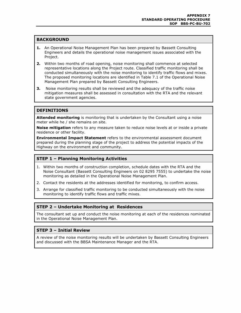
1. An Operational Noise Management Plan has been prepared by Bassett Consulting
Engineers and details the operational noise management issues associated with the
Project.
2. Within two months of road opening, noise monitoring shall commence at selected
representative locations along the Project route. Classified traffic monitoring shall be
conducted simultaneously with the noise monitoring to identify traffic flows and mixes.
The proposed monitoring locations are identified in Table 7.1 of the Operational Noise
Management Plan prepared by Bassett Consulting Engineers.
3. Noise monitoring results shall be reviewed and the adequacy of the traffic noise
mitigation measures shall be assessed in consultation with the RTA and the relevant
state government agencies.
DEFINITIONS
Attended monitoring is monitoring that is undertaken by the Consultant using a noise
meter while he / she remains on site.
Noise mitigation refers to any measure taken to reduce noise levels at or inside a private
residence or other facility.
Environmental Impact Statement refers to the environmental assessment document
prepared during the planning stage of the project to address the potential impacts of the
Highway on the environment and community.
STEP 1 – Planning Monitoring Activities
1. Within two months of construction completion, schedule dates with the RTA and the
Noise Consultant (Bassett Consulting Engineers on 02 8295 7555) to undertake the noise
monitoring as detailed in the Operational Noise Management Plan.
2. Contact the residents at the addresses identified for monitoring, to confirm access.
3. Arrange for classified traffic monitoring to be conducted simultaneously with the noise
monitoring to identify traffic flows and traffic mixes.
STEP 2 – Undertake Monitoring at Residences
The consultant set up and conduct the noise monitoring at each of the residences nominated
in the Operational Noise Management Plan.
STEP 3 – Initial Review
A review of the noise monitoring results will be undertaken by Bassett Consulting Engineers
and discussed with the BBSA Maintenance Manager and the RTA.
APPENDIX 7
STANDARD OPERATING PROCEDURE SOP BBS-PC-BU-702
STEP 4 – Consultation
Noise monitoring results shall be reviewed and the adequacy of the traffic noise mitigation
measures shall be assessed in consultation with the RTA, DECC (EPA & NPWS) and the
Planning Director-General.
Practice Note VIII of the ENMM requires that if post construction noise monitoring indicates
operational noise levels exceed the design noise level for Year 1 then certain follow-up
actions will be taken.
Refer to the Operational Noise Management Report for more details on consultation process
with the community.
STEP 5 – Final Report
A final operational noise report will be prepared to assess the adequacy of the traffic noise
mitigation measures. This is detailed in the Operational Noise Management Plan.
APPENDIX 7
STANDARD OPERATING PROCEDURE SOP BBS-PC-BU-703
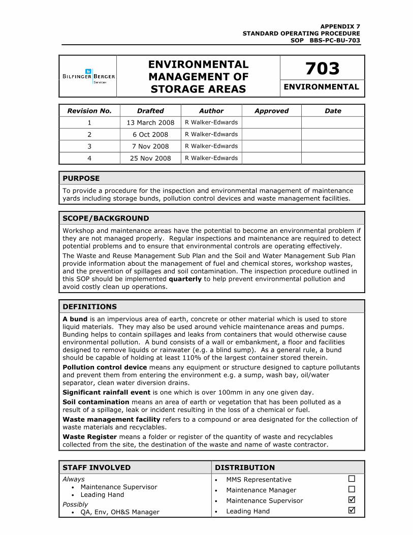
703 ENVIRONMENTAL
MANAGEMENT OF STORAGE AREAS ENVIRONMENTAL
Revision No. Drafted Author Approved Date
1 13 March 2008 R Walker-Edwards
2 6 Oct 2008 R Walker-Edwards
3 7 Nov 2008 R Walker-Edwards
4 25 Nov 2008 R Walker-Edwards
PURPOSE
To provide a procedure for the inspection and environmental management of maintenance
yards including storage bunds, pollution control devices and waste management facilities.
SCOPE/BACKGROUND
Workshop and maintenance areas have the potential to become an environmental problem if
they are not managed properly. Regular inspections and maintenance are required to detect
potential problems and to ensure that environmental controls are operating effectively.
The Waste and Reuse Management Sub Plan and the Soil and Water Management Sub Plan
provide information about the management of fuel and chemical stores, workshop wastes,
and the prevention of spillages and soil contamination. The inspection procedure outlined in
this SOP should be implemented quarterly to help prevent environmental pollution and
avoid costly clean up operations.
DEFINITIONS
A bund is an impervious area of earth, concrete or other material which is used to store
liquid materials. They may also be used around vehicle maintenance areas and pumps.
Bunding helps to contain spillages and leaks from containers that would otherwise cause
environmental pollution. A bund consists of a wall or embankment, a floor and facilities
designed to remove liquids or rainwater (e.g. a blind sump). As a general rule, a bund
should be capable of holding at least 110% of the largest container stored therein.
Pollution control device means any equipment or structure designed to capture pollutants
and prevent them from entering the environment e.g. a sump, wash bay, oil/water
separator, clean water diversion drains.
Significant rainfall event is one which is over 100mm in any one given day.
Soil contamination means an area of earth or vegetation that has been polluted as a
result of a spillage, leak or incident resulting in the loss of a chemical or fuel.
Waste management facility refers to a compound or area designated for the collection of
waste materials and recyclables.
Waste Register means a folder or register of the quantity of waste and recyclables
collected from the site, the destination of the waste and name of waste contractor.
STAFF INVOLVED DISTRIBUTION
Always
• Maintenance Supervisor
• Leading Hand
Possibly • QA, Env, OH&S Manager
• MMS Representative �
• Maintenance Manager �
• Maintenance Supervisor �
• Leading Hand �
APPENDIX 7
STANDARD OPERATING PROCEDURE SOP BBS-PC-BU-703
• RTA �
• Sub-contractor/Consultant �
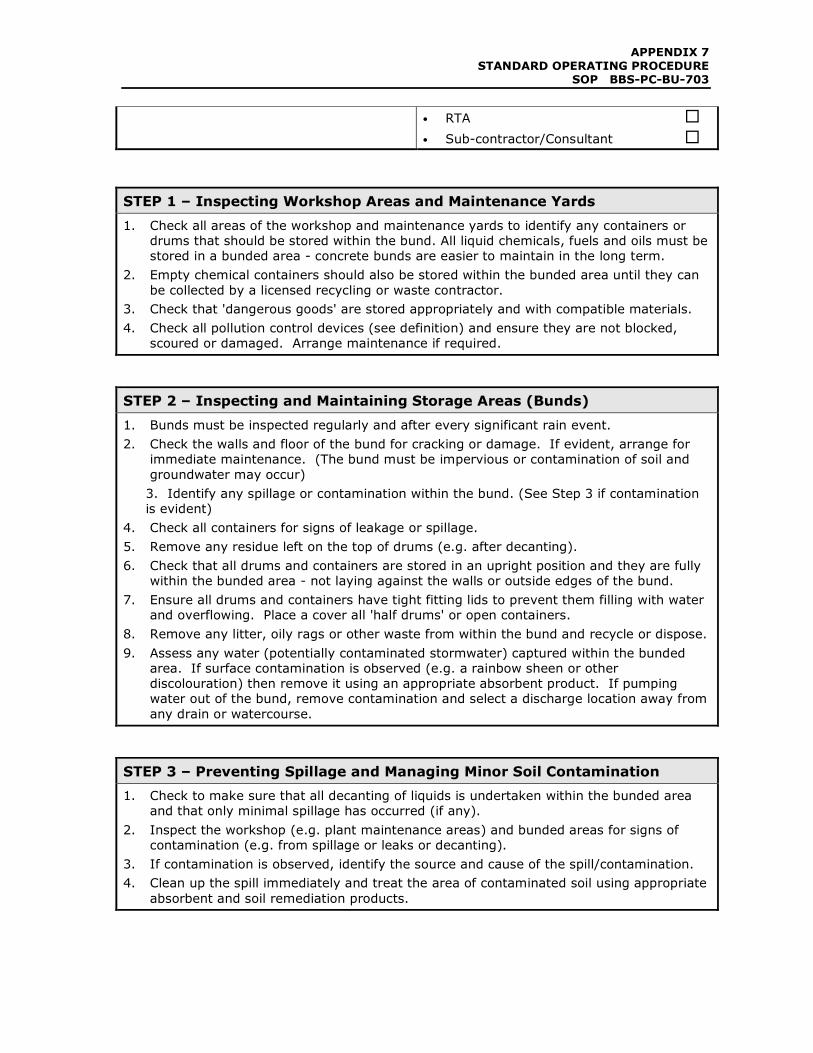
STEP 1 – Inspecting Workshop Areas and Maintenance Yards
1. Check all areas of the workshop and maintenance yards to identify any containers or
drums that should be stored within the bund. All liquid chemicals, fuels and oils must be
stored in a bunded area - concrete bunds are easier to maintain in the long term.
2. Empty chemical containers should also be stored within the bunded area until they can
be collected by a licensed recycling or waste contractor.
3. Check that 'dangerous goods' are stored appropriately and with compatible materials.
4. Check all pollution control devices (see definition) and ensure they are not blocked,
scoured or damaged. Arrange maintenance if required.
STEP 2 – Inspecting and Maintaining Storage Areas (Bunds)
1. Bunds must be inspected regularly and after every significant rain event.
2. Check the walls and floor of the bund for cracking or damage. If evident, arrange for
immediate maintenance. (The bund must be impervious or contamination of soil and
groundwater may occur)
3. Identify any spillage or contamination within the bund. (See Step 3 if contamination
is evident)
4. Check all containers for signs of leakage or spillage.
5. Remove any residue left on the top of drums (e.g. after decanting).
6. Check that all drums and containers are stored in an upright position and they are fully
within the bunded area - not laying against the walls or outside edges of the bund.
7. Ensure all drums and containers have tight fitting lids to prevent them filling with water
and overflowing. Place a cover all 'half drums' or open containers.
8. Remove any litter, oily rags or other waste from within the bund and recycle or dispose.
9. Assess any water (potentially contaminated stormwater) captured within the bunded
area. If surface contamination is observed (e.g. a rainbow sheen or other
discolouration) then remove it using an appropriate absorbent product. If pumping
water out of the bund, remove contamination and select a discharge location away from
any drain or watercourse.
STEP 3 – Preventing Spillage and Managing Minor Soil Contamination
1. Check to make sure that all decanting of liquids is undertaken within the bunded area
and that only minimal spillage has occurred (if any).
2. Inspect the workshop (e.g. plant maintenance areas) and bunded areas for signs of
contamination (e.g. from spillage or leaks or decanting).
3. If contamination is observed, identify the source and cause of the spill/contamination.
4. Clean up the spill immediately and treat the area of contaminated soil using appropriate
absorbent and soil remediation products.
APPENDIX 7
STANDARD OPERATING PROCEDURE SOP BBS-PC-BU-703
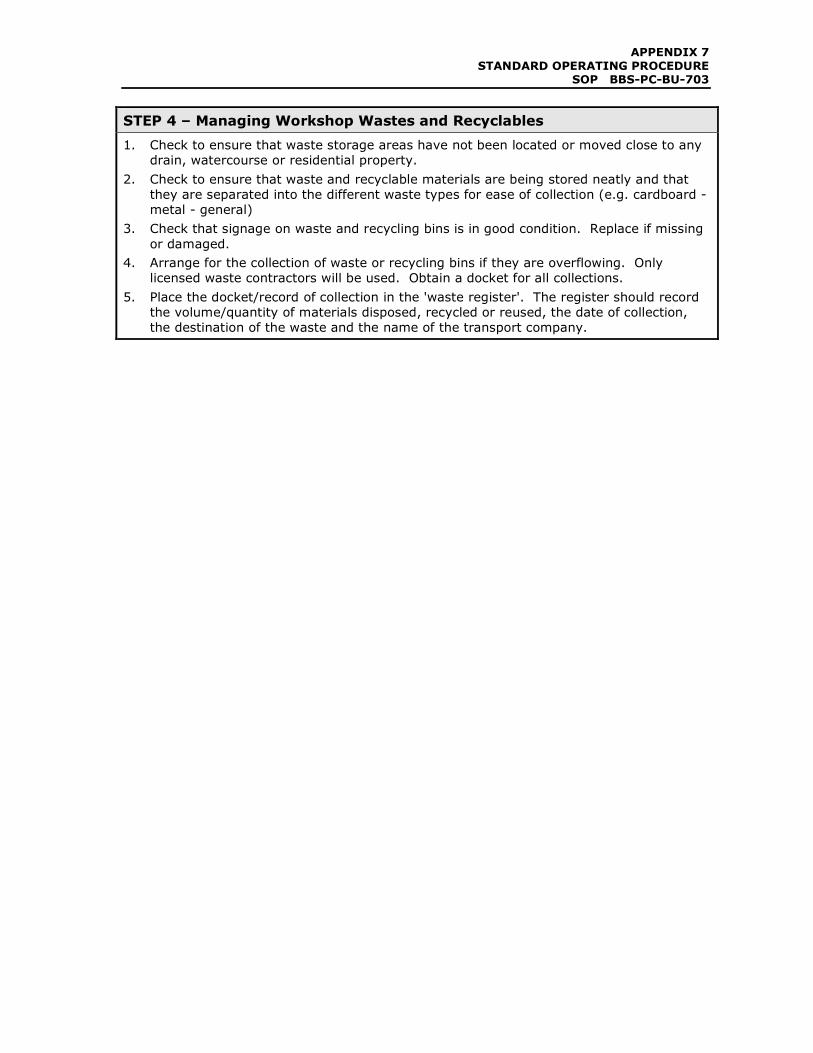
STEP 4 – Managing Workshop Wastes and Recyclables
1. Check to ensure that waste storage areas have not been located or moved close to any
drain, watercourse or residential property.
2. Check to ensure that waste and recyclable materials are being stored neatly and that
they are separated into the different waste types for ease of collection (e.g. cardboard -
metal - general)
3. Check that signage on waste and recycling bins is in good condition. Replace if missing
or damaged.
4. Arrange for the collection of waste or recycling bins if they are overflowing. Only
licensed waste contractors will be used. Obtain a docket for all collections.
5. Place the docket/record of collection in the 'waste register'. The register should record
the volume/quantity of materials disposed, recycled or reused, the date of collection,
the destination of the waste and the name of the transport company.
APPENDIX 7
STANDARD OPERATING PROCEDURE SOP BBS-PC-BU-705
705
MONITORING THREATENED PLANTS
ENVIRONMENTAL
Revision No. Drafted Author Approved Date
1 13 March 2008 R Walker-Edwards
2 6 Oct 2008 R Walker-Edwards
3 7 Nov 2008 R Walker-Edwards
4 25 Nov 2008 R Walker-Edwards
PURPOSE
To provide guidance to the Maintenance Supervisor and Leading Hand on the coordination
and implementation of monitoring for Threatened vegetation species roadside communities.
SCOPE/BACKGROUND
'Threatened' plant and animal species are protected under the Threatened Species
Conservation Act and must not be harmed or picked. Prior to construction commencement,
numerous threatened plant species were 'translocated' (moved) out of the road corridor into
secure areas on RTA and NPWS owned land. There are three translocation sites in total.
These plants will be monitored and maintained by the Project Ecologist for 3 years
from the date of translocation.
There are only two threatened plants which remained in the road reserve and not within the
translocation sites. The first is the Floyd’s grass which is located on the northern bank of
Bonville Creek. The other is one individual – one Macadamia tetraphylla which was
translocated to Chainage 98420. It was translocated from a residents backyard and does
not occur locally in the area, though is still a protected species. These do not require
monitoring.
DEFINITIONS
Threatened plant refers to a plant which has been identified as being endangered or
vulnerable because of its low numbers and/or a process which threatened its existence. It is
an offence to harm or pick a threatened species.
Translocated means that a plant has been removed from its original location and replanted
in an alternative location.
STAFF INVOLVED DISTRIBUTION
Always
• Maintenance Manager
• Maintenance Supervisor
Possibly
• QA, Env, OH&S Manager
• Leading Hand
• MMS Representative �
• Maintenance Manager �
• Maintenance Supervisor �
• Leading Hand �
• RTA �
• Sub-contractor/Consultant �
APPENDIX 7
STANDARD OPERATING PROCEDURE SOP BBS-PC-BU-705
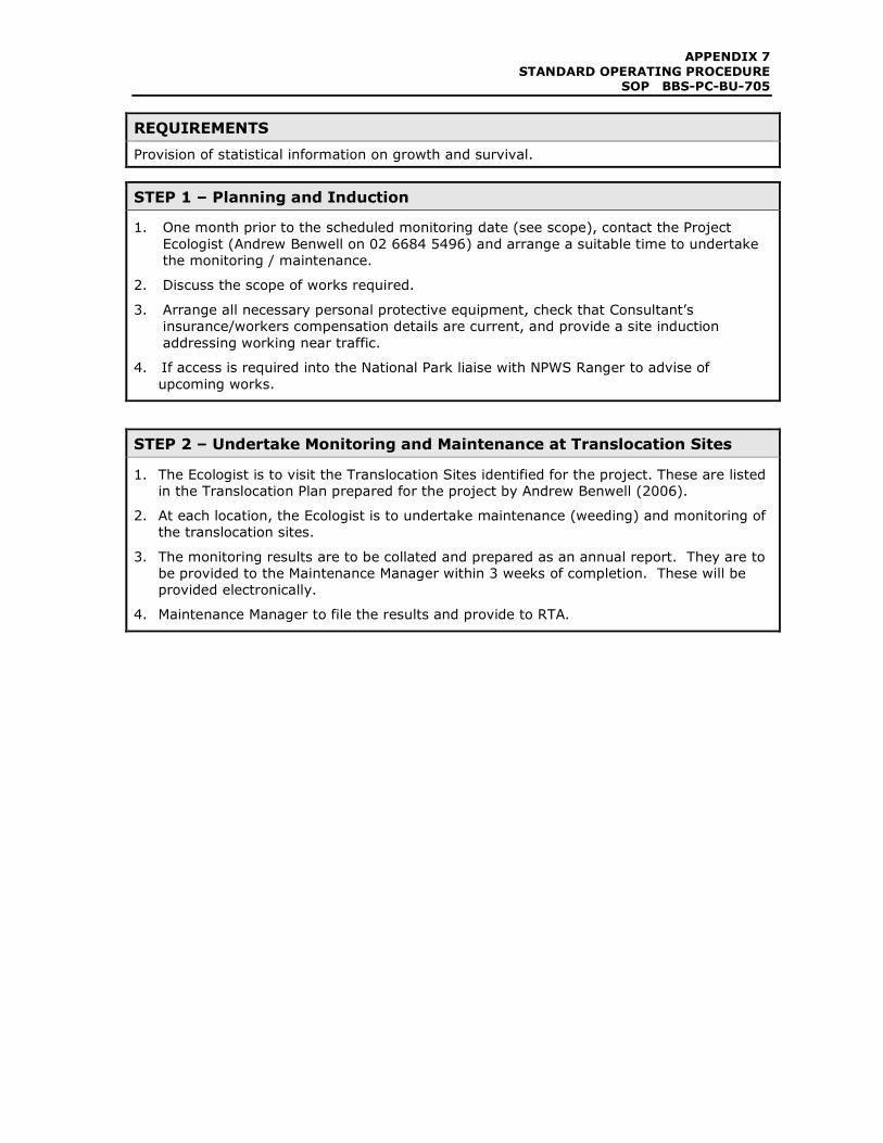
REQUIREMENTS
Provision of statistical information on growth and survival.
STEP 1 – Planning and Induction
1. One month prior to the scheduled monitoring date (see scope), contact the Project
Ecologist (Andrew Benwell on 02 6684 5496) and arrange a suitable time to undertake
the monitoring / maintenance.
2. Discuss the scope of works required.
3. Arrange all necessary personal protective equipment, check that Consultant’s
insurance/workers compensation details are current, and provide a site induction
addressing working near traffic.
4. If access is required into the National Park liaise with NPWS Ranger to advise of
upcoming works.
STEP 2 – Undertake Monitoring and Maintenance at Translocation Sites
1. The Ecologist is to visit the Translocation Sites identified for the project. These are listed
in the Translocation Plan prepared for the project by Andrew Benwell (2006).
2. At each location, the Ecologist is to undertake maintenance (weeding) and monitoring of
the translocation sites.
3. The monitoring results are to be collated and prepared as an annual report. They are to
be provided to the Maintenance Manager within 3 weeks of completion. These will be
provided electronically.
4. Maintenance Manager to file the results and provide to RTA.
APPENDIX 7
STANDARD OPERATING PROCEDURE SOP BBS-PC-BU-706
706
MANAGEMENT OF
SPILL BASINS ENVIRONMENTAL
Revision No. Drafted Author Approved Date
1 13 March 2008 R Walker-Edwards
2 6 Oct 2008 R Walker-Edwards
3 7 Nov 2008 R Walker-Edwards
4 25 Nov 2008 R Walker-Edwards
PURPOSE
To provide guidance on the inspection, management and maintenance of Water Quality Spill
Basins.
SCOPE/BACKGROUND
Water Quality Spill Basins have been constructed along the length of the highway upgrade
to capture road runoff and spillages occurring as a result of an incident or accident.
Regular inspections and maintenance of the basins will be required to ensure they remain in
good condition and continue to operate effectively, especially in an emergency situation.
DEFINITIONS
Water Quality Basin or Spill Basin refers to the basins that have been installed along the
project alignment to intercept runoff from the highway road surface prior to discharge off
the site. Some basins have been converted from sediment basins that were used during the
construction stage of the project.
A list of basins is attached to this SOP. The basins provide at least 20,000L capacity for the
capture of chemical spills and thus prevention of environmental pollution.
STAFF INVOLVED DISTRIBUTION
Always
• Maintenance Supervisor
• Leading Hand
Possibly
• Maintenance Manager
• QA, Env, OH&S Manager
• MMS Representative �
• Maintenance Manager �
• Maintenance Supervisor �
• Leading Hand �
• RTA �
• Sub-contractor/Consultant �
REQUIREMENTS
This procedure must be followed when inspecting a basin, or managing the basin after a
spill.
APPENDIX 7
STANDARD OPERATING PROCEDURE SOP BBS-PC-BU-706
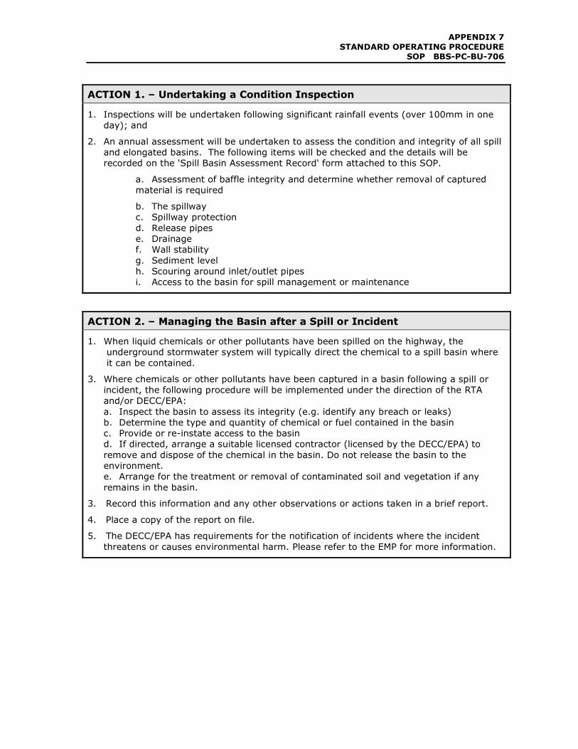
ACTION 1. – Undertaking a Condition Inspection
1. Inspections will be undertaken following significant rainfall events (over 100mm in one
day); and
2. An annual assessment will be undertaken to assess the condition and integrity of all spill
and elongated basins. The following items will be checked and the details will be
recorded on the 'Spill Basin Assessment Record' form attached to this SOP.
a. Assessment of baffle integrity and determine whether removal of captured
material is required
b. The spillway
c. Spillway protection
d. Release pipes
e. Drainage
f. Wall stability
g. Sediment level
h. Scouring around inlet/outlet pipes
i. Access to the basin for spill management or maintenance
ACTION 2. – Managing the Basin after a Spill or Incident
1. When liquid chemicals or other pollutants have been spilled on the highway, the
underground stormwater system will typically direct the chemical to a spill basin where
it can be contained.
3. Where chemicals or other pollutants have been captured in a basin following a spill or
incident, the following procedure will be implemented under the direction of the RTA
and/or DECC/EPA:
a. Inspect the basin to assess its integrity (e.g. identify any breach or leaks)
b. Determine the type and quantity of chemical or fuel contained in the basin
c. Provide or re-instate access to the basin
d. If directed, arrange a suitable licensed contractor (licensed by the DECC/EPA) to
remove and dispose of the chemical in the basin. Do not release the basin to the
environment.
e. Arrange for the treatment or removal of contaminated soil and vegetation if any
remains in the basin.
3. Record this information and any other observations or actions taken in a brief report.
4. Place a copy of the report on file.
5. The DECC/EPA has requirements for the notification of incidents where the incident
threatens or causes environmental harm. Please refer to the EMP for more information.
APPENDIX 7
STANDARD OPERATING PROCEDURE SOP BBS-PC-BU-706
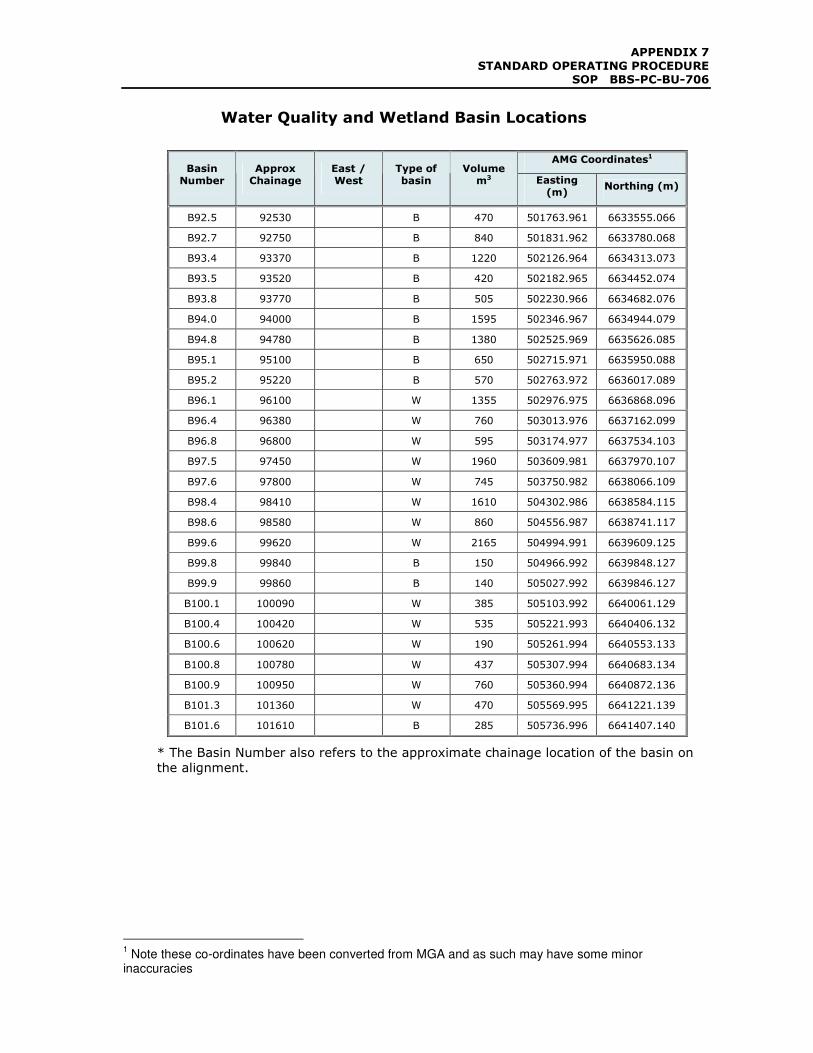
Water Quality and Wetland Basin Locations
AMG Coordinates1 Basin
Number Approx Chainage
East / West
Type of basin
Volume m3 Easting
(m) Northing (m)
B92.5 92530 B 470 501763.961 6633555.066
B92.7 92750 B 840 501831.962 6633780.068
B93.4 93370 B 1220 502126.964 6634313.073
B93.5 93520 B 420 502182.965 6634452.074
B93.8 93770 B 505 502230.966 6634682.076
B94.0 94000 B 1595 502346.967 6634944.079
B94.8 94780 B 1380 502525.969 6635626.085
B95.1 95100 B 650 502715.971 6635950.088
B95.2 95220 B 570 502763.972 6636017.089
B96.1 96100 W 1355 502976.975 6636868.096
B96.4 96380 W 760 503013.976 6637162.099
B96.8 96800 W 595 503174.977 6637534.103
B97.5 97450 W 1960 503609.981 6637970.107
B97.6 97800 W 745 503750.982 6638066.109
B98.4 98410 W 1610 504302.986 6638584.115
B98.6 98580 W 860 504556.987 6638741.117
B99.6 99620 W 2165 504994.991 6639609.125
B99.8 99840 B 150 504966.992 6639848.127
B99.9 99860 B 140 505027.992 6639846.127
B100.1 100090 W 385 505103.992 6640061.129
B100.4 100420 W 535 505221.993 6640406.132
B100.6 100620 W 190 505261.994 6640553.133
B100.8 100780 W 437 505307.994 6640683.134
B100.9 100950 W 760 505360.994 6640872.136
B101.3 101360 W 470 505569.995 6641221.139
B101.6 101610 B 285 505736.996 6641407.140
* The Basin Number also refers to the approximate chainage location of the basin on
the alignment.
1 Note these co-ordinates have been converted from MGA and as such may have some minor
inaccuracies
APPENDIX 7
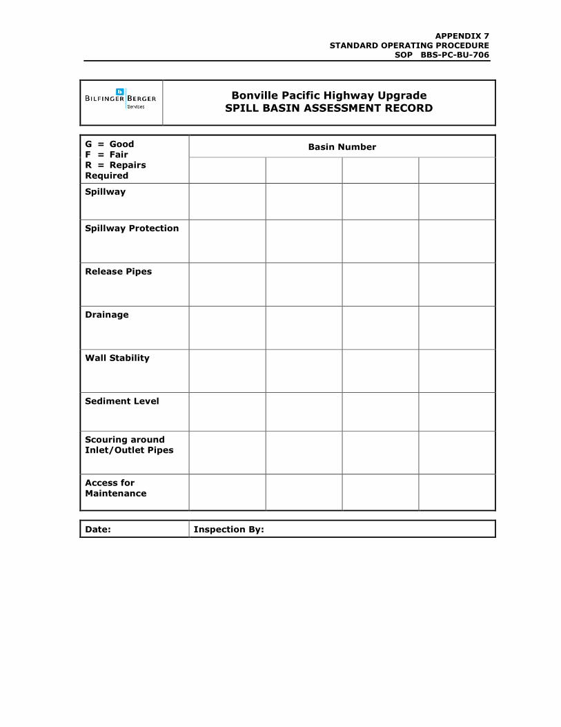
STANDARD OPERATING PROCEDURE SOP BBS-PC-BU-706
Bonville Pacific Highway Upgrade
SPILL BASIN ASSESSMENT RECORD
Basin Number G = Good
F = Fair
R = Repairs
Required
Spillway
Spillway Protection
Release Pipes
Drainage
Wall Stability
Sediment Level
Scouring around
Inlet/Outlet Pipes
Access for
Maintenance
Date: Inspection By:
APPENDIX 7
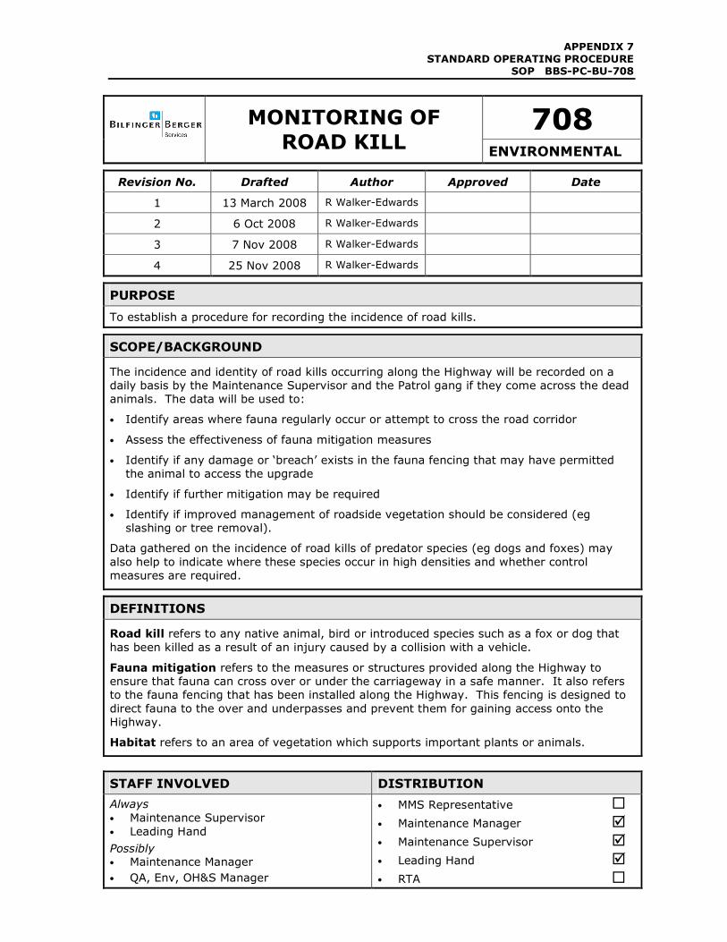
STANDARD OPERATING PROCEDURE SOP BBS-PC-BU-708
708
MONITORING OF
ROAD KILL ENVIRONMENTAL
Revision No. Drafted Author Approved Date
1 13 March 2008 R Walker-Edwards
2 6 Oct 2008 R Walker-Edwards
3 7 Nov 2008 R Walker-Edwards
4 25 Nov 2008 R Walker-Edwards
PURPOSE
To establish a procedure for recording the incidence of road kills.
SCOPE/BACKGROUND
The incidence and identity of road kills occurring along the Highway will be recorded on a
daily basis by the Maintenance Supervisor and the Patrol gang if they come across the dead
animals. The data will be used to:
• Identify areas where fauna regularly occur or attempt to cross the road corridor
• Assess the effectiveness of fauna mitigation measures
• Identify if any damage or ‘breach’ exists in the fauna fencing that may have permitted
the animal to access the upgrade
• Identify if further mitigation may be required
• Identify if improved management of roadside vegetation should be considered (eg
slashing or tree removal).
Data gathered on the incidence of road kills of predator species (eg dogs and foxes) may
also help to indicate where these species occur in high densities and whether control
measures are required.
DEFINITIONS
Road kill refers to any native animal, bird or introduced species such as a fox or dog that
has been killed as a result of an injury caused by a collision with a vehicle.
Fauna mitigation refers to the measures or structures provided along the Highway to
ensure that fauna can cross over or under the carriageway in a safe manner. It also refers
to the fauna fencing that has been installed along the Highway. This fencing is designed to
direct fauna to the over and underpasses and prevent them for gaining access onto the
Highway.
Habitat refers to an area of vegetation which supports important plants or animals.
STAFF INVOLVED DISTRIBUTION
Always
• Maintenance Supervisor
• Leading Hand
Possibly • Maintenance Manager
• QA, Env, OH&S Manager
• MMS Representative �
• Maintenance Manager �
• Maintenance Supervisor �
• Leading Hand �
• RTA �

APPENDIX 7
STANDARD OPERATING PROCEDURE SOP BBS-PC-BU-708
• Sub-contractor/Consultant �
APPENDIX 7
STANDARD OPERATING PROCEDURE SOP BBS-PC-BU-708
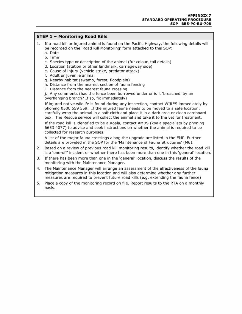
STEP 1 – Monitoring Road Kills
1. If a road kill or injured animal is found on the Pacific Highway, the following details will
be recorded on the ‘Road Kill Monitoring’ form attached to this SOP:
a. Date
b. Time
c. Species type or description of the animal (fur colour, tail details)
d. Location (station or other landmark, carriageway side)
e. Cause of injury (vehicle strike, predator attack)
f. Adult or juvenile animal
g. Nearby habitat (swamp, forest, floodplain)
h. Distance from the nearest section of fauna fencing
i. Distance from the nearest fauna crossing
j. Any comments (has the fence been burrowed under or is it ‘breached’ by an
overhanging branch? If so, fix immediately)
If injured native wildlife is found during any inspection, contact WIRES immediately by
phoning 0500 559 559. If the injured fauna needs to be moved to a safe location,
carefully wrap the animal in a soft cloth and place it in a dark area or clean cardboard
box. The Rescue service will collect the animal and take it to the vet for treatment.
If the road kill is identified to be a Koala, contact AMBS (koala specialists by phoning
6653 4077) to advise and seek instructions on whether the animal is required to be
collected for research purposes.
A list of the major fauna crossings along the upgrade are listed in the EMP. Further
details are provided in the SOP for the ‘Maintenance of Fauna Structures’ (M6).
2. Based on a review of previous road kill monitoring results, identify whether the road kill
is a ‘one-off’ incident or whether there has been more than one in this ‘general’ location.
3. If there has been more than one in the ‘general’ location, discuss the results of the
monitoring with the Maintenance Manager.
4. The Maintenance Manager will arrange an assessment of the effectiveness of the fauna
mitigation measures in this location and will also determine whether any further
measures are required to prevent future road kills (e.g. extending the fauna fence)
5. Place a copy of the monitoring record on file. Report results to the RTA on a monthly
basis.
APPENDIX 7
STANDARD OPERATING PROCEDURE SOP BBS-PC-BU-708
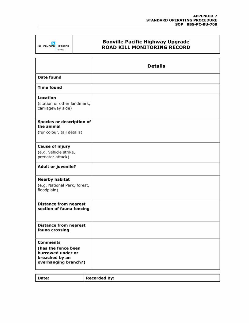
Bonville Pacific Highway Upgrade ROAD KILL MONITORING RECORD
Details
Date found
Time found
Location
(station or other landmark,
carriageway side)
Species or description of
the animal
(fur colour, tail details)
Cause of injury
(e.g. vehicle strike,
predator attack)
Adult or juvenile?
Nearby habitat
(e.g. National Park, forest,
floodplain)
Distance from nearest
section of fauna fencing
Distance from nearest
fauna crossing
Comments
(has the fence been
burrowed under or
breached by an
overhanging branch?)
Date: Recorded By:
APPENDIX 7
STANDARD OPERATING PROCEDURE SOP BBS-PC-BU-709
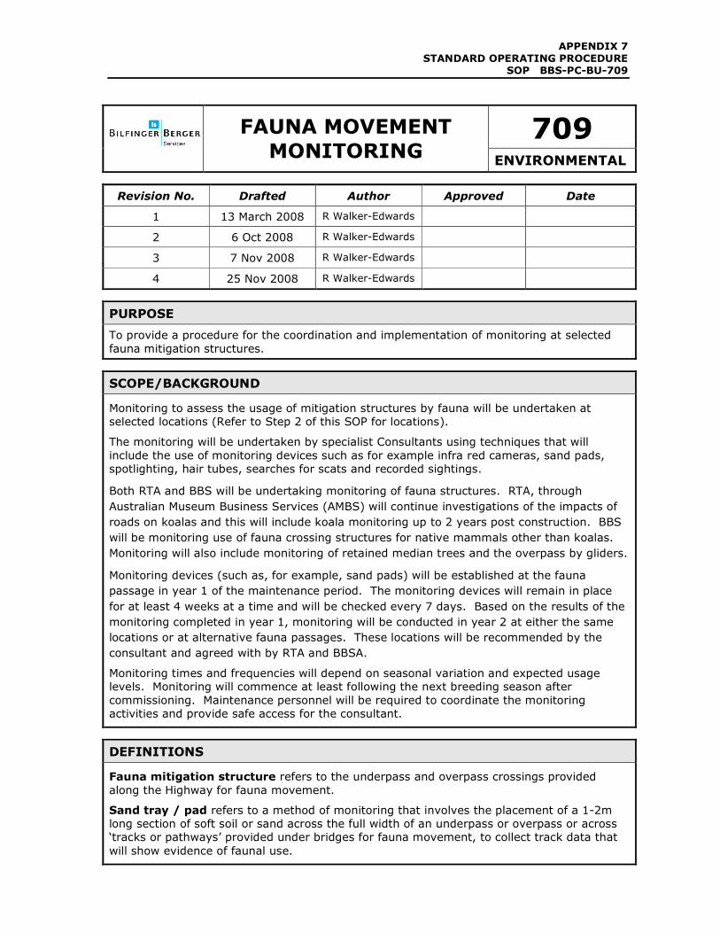
709
FAUNA MOVEMENT
MONITORING ENVIRONMENTAL
Revision No. Drafted Author Approved Date
1 13 March 2008 R Walker-Edwards
2 6 Oct 2008 R Walker-Edwards
3 7 Nov 2008 R Walker-Edwards
4 25 Nov 2008 R Walker-Edwards
PURPOSE
To provide a procedure for the coordination and implementation of monitoring at selected
fauna mitigation structures.
SCOPE/BACKGROUND
Monitoring to assess the usage of mitigation structures by fauna will be undertaken at
selected locations (Refer to Step 2 of this SOP for locations).
The monitoring will be undertaken by specialist Consultants using techniques that will
include the use of monitoring devices such as for example infra red cameras, sand pads,
spotlighting, hair tubes, searches for scats and recorded sightings.
Both RTA and BBS will be undertaking monitoring of fauna structures. RTA, through
Australian Museum Business Services (AMBS) will continue investigations of the impacts of
roads on koalas and this will include koala monitoring up to 2 years post construction. BBS
will be monitoring use of fauna crossing structures for native mammals other than koalas.
Monitoring will also include monitoring of retained median trees and the overpass by gliders.
Monitoring devices (such as, for example, sand pads) will be established at the fauna
passage in year 1 of the maintenance period. The monitoring devices will remain in place
for at least 4 weeks at a time and will be checked every 7 days. Based on the results of the
monitoring completed in year 1, monitoring will be conducted in year 2 at either the same
locations or at alternative fauna passages. These locations will be recommended by the
consultant and agreed with by RTA and BBSA.
Monitoring times and frequencies will depend on seasonal variation and expected usage
levels. Monitoring will commence at least following the next breeding season after
commissioning. Maintenance personnel will be required to coordinate the monitoring
activities and provide safe access for the consultant.
DEFINITIONS
Fauna mitigation structure refers to the underpass and overpass crossings provided
along the Highway for fauna movement.
Sand tray / pad refers to a method of monitoring that involves the placement of a 1-2m
long section of soft soil or sand across the full width of an underpass or overpass or across
‘tracks or pathways’ provided under bridges for fauna movement, to collect track data that
will show evidence of faunal use.
APPENDIX 7
STANDARD OPERATING PROCEDURE SOP BBS-PC-BU-709
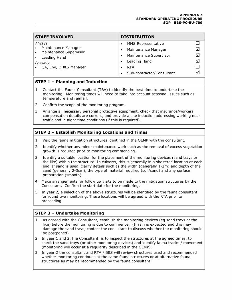
STAFF INVOLVED DISTRIBUTION
Always
• Maintenance Manager
• Maintenance Supervisor
• Leading Hand
Possibly • QA, Env, OH&S Manager
• MMS Representative �
• Maintenance Manager �
• Maintenance Supervisor �
• Leading Hand �
• RTA �
• Sub-contractor/Consultant �
STEP 1 – Planning and Induction
1. Contact the Fauna Consultant (TBA) to identify the best time to undertake the
monitoring. Monitoring times will need to take into account seasonal issues such as
temperature and rainfall.
2. Confirm the scope of the monitoring program.
3. Arrange all necessary personal protective equipment, check that insurance/workers
compensation details are current, and provide a site induction addressing working near
traffic and in night time conditions (if this is required).
STEP 2 – Establish Monitoring Locations and Times
1. Visit the fauna mitigation structures identified in the OEMP with the consultant.
2. Identify whether any minor maintenance work such as the removal of excess vegetation
growth is required prior to monitoring commencing.
3. Identify a suitable location for the placement of the monitoring devices (sand trays or
the like) within the structure. In culverts, this is generally in a sheltered location at each
end. If sand is used, clarify details such as the width (generally 1-2m) and depth of the
sand (generally 2-3cm), the type of material required (soil/sand) and any surface
preparation (smooth).
4. Make arrangements for follow up visits to be made to the mitigation structures by the
Consultant. Confirm the start date for the monitoring.
5. In year 2, a selection of the above structures will be identified by the fauna consultant
for round two monitoring. These locations will be agreed with the RTA prior to
proceeding.
STEP 3 – Undertake Monitoring
1. As agreed with the Consultant, establish the monitoring devices (eg sand trays or the
like) before the monitoring is due to commence. (If rain is expected and this may
damage the sand trays, contact the consultant to discuss whether the monitoring should
be postponed)
2. In year 1 and 2, the Consultant is to inspect the structures at the agreed times, to
check the sand trays (or other monitoring devices) and identify fauna tracks / movement
(monitoring will occur at a regularity described in the OEMP).
3. In year 2 the consultant and RTA / BBS will review structures used and recommended
whether monitoring continues at the same fauna structures or at alternative fauna
structures as may be recommended by the fauna consultant.
APPENDIX 7
STANDARD OPERATING PROCEDURE SOP BBS-PC-BU-709
STEP 4 – Review Results
1. Request a report from the Consultant outlining the timing, method and results of the
monitoring.
2. Refer a copy of the report to the Maintenance Manager and Group Environmental
Manager for their information and review.
3. Provide a copy to the RTA.
4. The Maintenance Manager may consider improvements arising from the
recommendations of the Consultant.
PPENDIX 7
STANDARD OPERATING PROCEDURE SOP BBS-PC-BU-711
711
WATER QUALITY
MONITORING ENVIRONMENTAL
Revision No. Drafted Author Approved Date
1 13 March 2008 R Walker-Edwards
2 6 Oct 2008 R Walker-Edwards
3 7 Nov 2008 R Walker-Edwards
4 25 Nov 2008 R Walker-Edwards
PURPOSE
To provide guidance to the Maintenance Supervisor on the coordination and implementation
of water quality monitoring activities.
SCOPE/BACKGROUND
Water quality monitoring is required during the first 6 months of the contract maintenance
period. The monitoring will be conducted on a monthly basis at six (6) sites along the
highway alignment by BBSA. Maintenance personnel will be required to assist by providing
safe access to the monitoring sites.
Further details about the monitoring program can be found in Section 5 of the Soil and
Water Sub Plan of the Environmental Management Plan (Maintenance).
DEFINITIONS
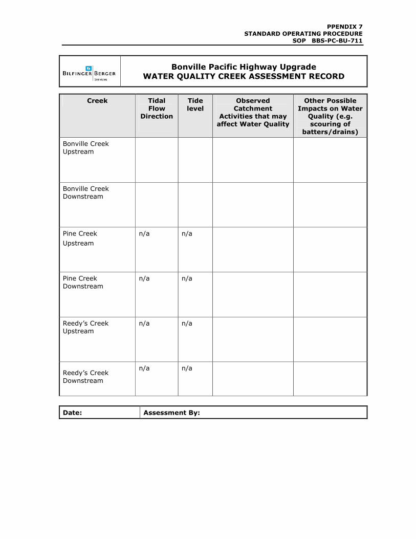
Water quality creek assessment record refers to the form attached to this SOP. This
form will be used to record details of the waterway being monitored e.g. flow and
approximate depth.
Water quality monitoring means assessing the characteristics of nominated surface
waters.
Water quality parameters refers to the variables or different types of tests that are
required to be undertaken. Some parameters can be tested in the field (e.g. pH and
temperature) while others require a laboratory analysis (e.g. total suspended solids).
Consultant refers to a specialist contractor with the experience and resources (equipment)
to undertake water quality monitoring and analysis.
REQUIREMENTS
Water leaving the site should be better than or equal in quality to the water entering the
site.
STAFF INVOLVED DISTRIBUTION
Always
• Maintenance Supervisor
• Leading Hand
Possibly • Maintenance Manager
• QA, Env, OH&S Manager
• MMS Representative �
• Maintenance Manager �
• Maintenance Supervisor �
• Leading Hand �
• RTA �

PPENDIX 7
STANDARD OPERATING PROCEDURE SOP BBS-PC-BU-711
• Sub-contractor/Consultant �
PPENDIX 7
STANDARD OPERATING PROCEDURE SOP BBS-PC-BU-711
STEP 1 – Planning and Induction
1. At least one week prior to the scheduled monitoring date, contact Abigroup’s
Environmental Scientist/Engineer (via the NSW Environmental Manager – Rebecca
Walker-Edwards Phone 9499 0999) and arrange a suitable time to undertake the
monitoring. Monitoring should target both dry periods or wet-weather events.
2. Discuss the scope of works required including the water quality parameters that will be
assessed. This will allow staff to arrange the appropriate equipment and sample bottles
and to calibrate the monitoring units.
3. The Environmental Scientist/Engineer will contact Coffs Harbour City Council
Environmental Laboratory 02 6648 4460, to advise that samples will be provided on
(date) for analysis.
4. Arrange all necessary personal protective equipment and provide a site induction
addressing working near traffic.
STEP 2 – Undertake the Monitoring
1. Visit each of the 6 sites identified below:
a) Bonville Creek upstream;
b) Bonville Creek downstream;
c) Pine Creek upstream;
d) Pine Creek downstream;
e) Reedy’s Creek upstream;
f) Reedy’s Creek downstream.
2. The Environmental Scientist/Engineer will assess water quality with a field probe and
collect required samples in prepared bottles. The following parameters will be tested on
a monthly basis (for the first 6 months) in the field:
• pH;
• salinity / conductivity;
• dissolved oxygen;
• turbidity/TSS;
• temperature.
3. Using the ‘Water Quality Creek Assessment Record’ form attached, the Environmental
Scientist/Engineer or accompanying maintenance person will record the following details
at the time of monitoring:
• tide (only Bonville Creek is tidal at monitoring locations);
• direction of tidal movement (only Bonville Creek is tidal at monitoring locations);
• any activities noted to be occurring within the catchment that could affect water
quality;
• any aspect of the immediate environment that could affect water quality eg
scouring/stability of batters, drains etc.
The Environmental Scientist/Engineer will review the results of the water quality
monitoring and compare the data for the up and downstream monitoring sites. A brief
report including an analysis of the results, will be prepared and provided to maintenance
personnel.
4. File the Water Quality Creek Assessment Record with a copy of the water quality results
and report provided by the Environmental Scientist/Engineer. Results should be
requested within 1 week of monitoring being undertaken.
5. If at the time of monitoring, a maintenance or environmental issue of concern is
PPENDIX 7
STANDARD OPERATING PROCEDURE SOP BBS-PC-BU-711
identified (e.g. batter or drain scour), arrange an inspection and/or rectification work as
soon as practical.
STEP 3 – Distributing and Reviewing the Results
1. Within one (1) week of receiving the water quality results, copy and send them to the
Maintenance Manager for review. A copy of the information recorded on the attached
‘Water Quality Creek Assessment Record’ should also be sent.
2. The Maintenance Manager, in conjunction with the Maintenance Supervisor, will assess
and compare the up and downstream monitoring results and review the report provided
by the Environmental Scientist/Engineer. Where a difference (significant) between the
up and downstream results was observed and the reason for the difference was not
identified or recorded at the time of monitoring, the Manager may require an inspection
of the area to be undertaken to identify any possible source or cause of the water
quality issue.
3. Record the outcome of the inspection and place the details on file. Where required,
arrange rectification works.
4. Provide this information to RTA. RTA are to forward them to any relevant agency such
as DECC as required.
PPENDIX 7
STANDARD OPERATING PROCEDURE SOP BBS-PC-BU-711
Bonville Pacific Highway Upgrade
WATER QUALITY CREEK ASSESSMENT RECORD
Creek Tidal
Flow
Direction
Tide
level
Observed
Catchment
Activities that may
affect Water Quality
Other Possible
Impacts on Water
Quality (e.g.
scouring of
batters/drains)
Bonville Creek
Upstream
Bonville Creek
Downstream
Pine Creek
Upstream
n/a n/a
Pine Creek
Downstream
n/a n/a
Reedy’s Creek
Upstream
n/a n/a
Reedy’s Creek
Downstream
n/a n/a
Date: Assessment By:
APPENDIX 7
STANDARD OPERATING PROCEDURE SOP BBS-PC-BU-712
712
MANAGING ACID
SULFATE SOILS ENVIRONMENTAL
Revision No. Drafted Author Approved Date
1 13 March 2008 R Walker-Edwards
2 6 Oct 2008 R Walker-Edwards
3 7 Nov 2008 R Walker-Edwards
4 25 Nov 2008 R Walker-Edwards
PURPOSE
To provide guidance on the management of acid sulfate soils (ASS).
SCOPE/BACKGROUND
When exposed to the air, potential acid sulfate soil (PASS) has the potential to produce acid
which can flow into drains and creek lines. This can result in a change in water quality and
can result in fish kills.
Some PASS and ASS are located close to the surface but they can also extend several
meters underground. They are generally dark grey, muddy clays, sands or peats and may
have orange or red mottles in them. On exposure to air these muds dry to a pale grey with
rust coloured root channels.
Maintenance activities such as minor earthworks in low lying areas or the maintenance of
drains have the potential to disturb PASS and ASS and cause harm to the environment.
Maintenance activities will be planned and implemented so that they do not have an adverse
impact on the environment as a result of ASS disturbance.
DEFINITIONS
Acid Sulfate Soils (ASS) formed naturally in geological timeframes. If deprived of oxygen
they pose no environmental harm. If exposed to oxygen, the soil oxidises and can produce
excess sulfuric acid. In general, land surface levels below RL 5m (AHD) could be ASS.
Lime barrier system means using agricultural lime, lime chip or cobbles as a barrier or
neutralising agent for acid production. Fine aglime can be spread over the surface of an
newly excavated area while lime chip and cobbles can be used as check structures or
wrapped in geofabric and used as a groyne or sausage.
REQUIREMENTS
If potential ASS are encountered and disturbed, controls as detailed in Step 2 must be
implemented.
STAFF INVOLVED DISTRIBUTION
Always
• Maintenance Supervisor
• Leading Hand
Possibly • Maintenance Manager
• QA, Env, OH&S Manager
• MMS Representative �
• Maintenance Manager �
• Maintenance Supervisor �
• Leading Hand �
• RTA �

APPENDIX 7
STANDARD OPERATING PROCEDURE SOP BBS-PC-BU-712
• Sub-contractor/Consultant �
APPENDIX 7
STANDARD OPERATING PROCEDURE SOP BBS-PC-BU-712
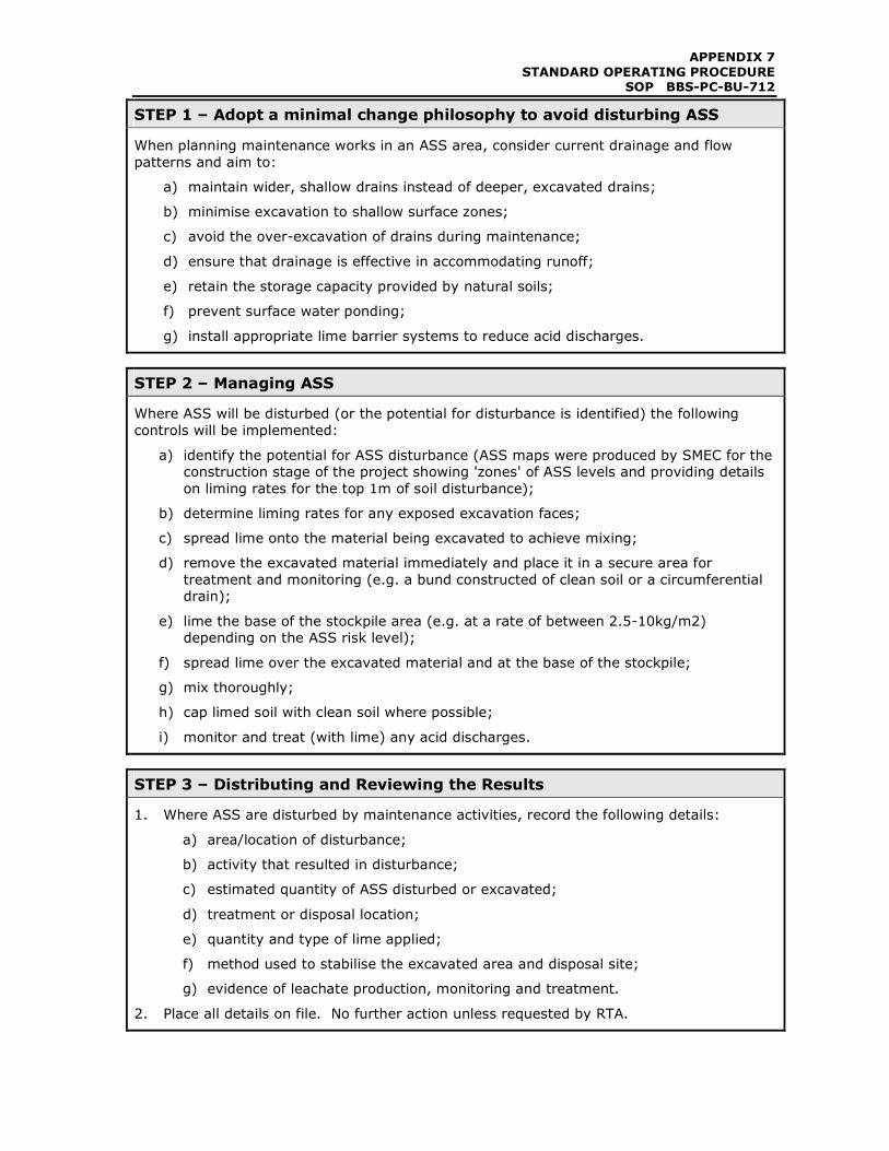
STEP 1 – Adopt a minimal change philosophy to avoid disturbing ASS
When planning maintenance works in an ASS area, consider current drainage and flow
patterns and aim to:
a) maintain wider, shallow drains instead of deeper, excavated drains;
b) minimise excavation to shallow surface zones;
c) avoid the over-excavation of drains during maintenance;
d) ensure that drainage is effective in accommodating runoff;
e) retain the storage capacity provided by natural soils;
f) prevent surface water ponding;
g) install appropriate lime barrier systems to reduce acid discharges.
STEP 2 – Managing ASS
Where ASS will be disturbed (or the potential for disturbance is identified) the following
controls will be implemented:
a) identify the potential for ASS disturbance (ASS maps were produced by SMEC for the
construction stage of the project showing 'zones' of ASS levels and providing details
on liming rates for the top 1m of soil disturbance);
b) determine liming rates for any exposed excavation faces;
c) spread lime onto the material being excavated to achieve mixing;
d) remove the excavated material immediately and place it in a secure area for
treatment and monitoring (e.g. a bund constructed of clean soil or a circumferential
drain);
e) lime the base of the stockpile area (e.g. at a rate of between 2.5-10kg/m2)
depending on the ASS risk level);
f) spread lime over the excavated material and at the base of the stockpile;
g) mix thoroughly;
h) cap limed soil with clean soil where possible;
i) monitor and treat (with lime) any acid discharges.
STEP 3 – Distributing and Reviewing the Results
1. Where ASS are disturbed by maintenance activities, record the following details:
a) area/location of disturbance;
b) activity that resulted in disturbance;
c) estimated quantity of ASS disturbed or excavated;
d) treatment or disposal location;
e) quantity and type of lime applied;
f) method used to stabilise the excavated area and disposal site;
g) evidence of leachate production, monitoring and treatment.
2. Place all details on file. No further action unless requested by RTA.
APPENDIX 7
STANDARD OPERATING PROCEDURE SOP BBS-PC-BU-713
713
MAINTENANCE AT WATERWAYS
ENVIRONMENTAL
Revision No. Drafted Author Approved Date
1 13 March 2008 R Walker-Edwards
2 6 Oct 2008 R Walker-Edwards
3 7 Nov 2008 R Walker-Edwards
PURPOSE
To provide guidance for the inspections and maintenance of assets at waterways.
BACKGROUND
The Bonville Pacific Highway Upgrade crosses a number of waterways including Pine Creek
and Bonville Creek. Many other minor waterways are also tributaries of these.
During or after a large rainfall event, waterways can become obstructed with debris or
sediment, particularly adjoining a structure.
The removal of obstructions (debris or sediment) from waterways can have an impact on the
environment if not undertaken sensitively.
DEFINITIONS
Waterway refers to any watercourse. This could be major natural systems such as Pine
Creek, or could be ephemeral drainage systems such as the flow paths at culverts along the
Bonville upgrade.
STAFF INVOLVED DISTRIBUTION
Always
• Maintenance Manager
• Maintenance Supervisor
Possibly
• MMS Representative
• QA, Env, OH&S Manager
• Leading Hand
• MMS Representative �
• Maintenance Manager �
• Maintenance Supervisor �
• Leading Hand �
• RTA �
• Sub-contractor/Consultant �
APPENDIX 7
STANDARD OPERATING PROCEDURE SOP BBS-PC-BU-713
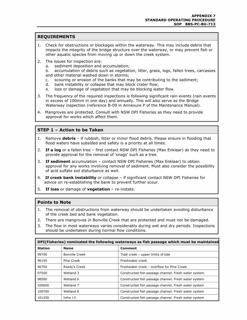
REQUIREMENTS
1. Check for obstructions or blockages within the waterway. This may include debris that
impacts the integrity of the bridge structure over the waterway, or may prevent fish or
other aquatic species from moving up or down the creek system.
2. The issues for inspection are:
a. sediment deposition and accumulation;
b. accumulation of debris such as vegetation, litter, grass, logs, fallen trees, carcasses
and other material washed down in storms;
c. scouring or erosion of the banks that may be contributing to the sediment;
d. bank instability or collapse that may block crater flow;
e. loss or damage of vegetation that may be blocking water flow.
3. The frequency of the required inspections is following significant rain events (rain events
in excess of 100mm in one day) and annually. This will also serve as the Bridge
Waterway inspection (reference B-09 in Annexure P of the Maintenance Manual).
4. Mangroves are protected. Consult with NSW DPI Fisheries as they need to provide
approval for works which affect them.
STEP 1 – Action to be Taken
1. Remove debris – if rubbish, litter or minor flood debris. Please ensure in flooding that
flood waters have subsided and safety is a priority at all times.
2. If a log or a fallen tree – first contact NSW DPI Fisheries (Max Enklaar) as they need to
provide approval for the removal of ‘snags’ such as a tree.
3. If sediment accumulation – contact NSW DPI Fisheries (Max Enklaar) to obtain
approval for any works involving removal of sediment. Must also consider the possibility
of acid sulfate soil disturbance as well.
4. If creek bank instability or collapse – if significant contact NSW DPI Fisheries for
advice on re-establishing the bank to prevent further scour.
5. If loss or damage of vegetation – re-instate.
Points to Note
1. The removal of obstructions from waterway should be undertaken avoiding disturbance
of the creek bed and bank vegetation.
2. There are mangroves in Bonville Creek that are protected and must not be damaged.
3. The flow in most waterways varies considerably during wet and dry periods. Inspections
should be undertaken during normal flow conditions.
DPI(Fisheries) nominated the following waterways as fish passage which must be maintained:
Station Name Comment
99700 Bonville Creek Tidal creek – upper limits of tide
96150 Pine Creek Freshwater creek.
96700 Reedy’s Creek Freshwater creek – overflow for Pine Creek.
97500 Wetland 3 Constructed fish passage channel. Fresh water system.
98500 Wetland 6 Constructed fish passage channel. Fresh water system
100600 Wetland 7 Constructed fish passage channel. Fresh water system
100700 Wetland 8 Constructed fish passage channel. Fresh water system
101250 Infra 13 Constructed fish passage channel. Fresh water system
APPENDIX 7
STANDARD OPERATING PROCEDURE SOP BBS-PC-BU-714
101250
714
ENVIRONMENTAL RISK
ASSESSMENT ENVIRONMENTAL
Revision No. Drafted Author Approved Date
1 13 March 2008 R Walker-Edwards
2 6 Oct 2008 R Walker-Edwards
3 7 Nov 2008 R Walker-Edwards
4 25 Nov 2008 R Walker-Edwards
PURPOSE
To provide Abigroup Personnel and Contractors with a process enabling them to identify and
assess actual and potential environmental hazards & risks associated with maintenance
activities and to determine the controls required to prevent or control the identified hazards
or risks.
BACKGROUND
Many of the tasks undertaken by Abigroup throughout the maintenance phase have the
potential to impact on the surrounding environment unless proper controls are in place.
Forward planning of maintenance tasks are required to ensure that all environmental risks
and hazards are appropriately identified prior to undertaking the maintenance activities.
Once identified, controls can be developed and crews trained to prevent the works impacting
on the environment.
Poor management of environmental risks can lead to extensive damage or impacts to the
surrounding environment be it natural or domestic and a source of bad publicity to the
Abigroup Maintenance Crews. It may also lead to substantial fines being imposed from the
various environmental agencies.
STAFF INVOLVED DISTRIBUTION
Always
• Maintenance Manager
• Maintenance Supervisor
Possibly
• MMS Representative
• QA, Env, OH&S Manager
• Leading Hand
• MMS Representative �
• Maintenance Manager �
• Maintenance Supervisor �
• Leading Hand �
• RTA �
• Sub-contractor/Consultant �
APPENDIX 7
STANDARD OPERATING PROCEDURE SOP BBS-PC-BU-714
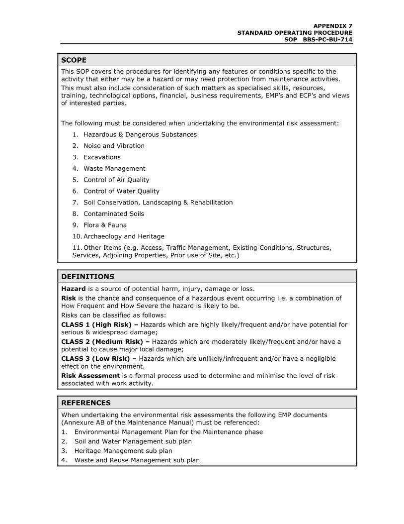
SCOPE
This SOP covers the procedures for identifying any features or conditions specific to the
activity that either may be a hazard or may need protection from maintenance activities.
This must also include consideration of such matters as specialised skills, resources,
training, technological options, financial, business requirements, EMP’s and ECP’s and views
of interested parties.
The following must be considered when undertaking the environmental risk assessment:
1. Hazardous & Dangerous Substances
2. Noise and Vibration
3. Excavations
4. Waste Management
5. Control of Air Quality
6. Control of Water Quality
7. Soil Conservation, Landscaping & Rehabilitation
8. Contaminated Soils
9. Flora & Fauna
10. Archaeology and Heritage
11. Other Items (e.g. Access, Traffic Management, Existing Conditions, Structures,
Services, Adjoining Properties, Prior use of Site, etc.)
DEFINITIONS
Hazard is a source of potential harm, injury, damage or loss.
Risk is the chance and consequence of a hazardous event occurring i.e. a combination of
How Frequent and How Severe the hazard is likely to be.
Risks can be classified as follows:
CLASS 1 (High Risk) – Hazards which are highly likely/frequent and/or have potential for
serious & widespread damage;
CLASS 2 (Medium Risk) – Hazards which are moderately likely/frequent and/or have a
potential to cause major local damage;
CLASS 3 (Low Risk) – Hazards which are unlikely/infrequent and/or have a negligible
effect on the environment.
Risk Assessment is a formal process used to determine and minimise the level of risk
associated with work activity.
REFERENCES
When undertaking the environmental risk assessments the following EMP documents
(Annexure AB of the Maintenance Manual) must be referenced:
1. Environmental Management Plan for the Maintenance phase
2. Soil and Water Management sub plan
3. Heritage Management sub plan
4. Waste and Reuse Management sub plan
APPENDIX 7
STANDARD OPERATING PROCEDURE SOP BBS-PC-BU-714
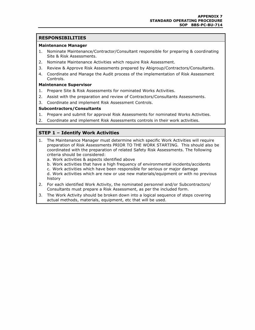
RESPONSIBILITIES
Maintenance Manager
1. Nominate Maintenance/Contractor/Consultant responsible for preparing & coordinating
Site & Risk Assessments.
2. Nominate Maintenance Activities which require Risk Assessment.
3. Review & Approve Risk Assessments prepared by Abigroup/Contractors/Consultants.
4. Coordinate and Manage the Audit process of the implementation of Risk Assessment
Controls.
Maintenance Supervisor
1. Prepare Site & Risk Assessments for nominated Works Activities.
2. Assist with the preparation and review of Contractors/Consultants Assessments.
3. Coordinate and implement Risk Assessment Controls.
Subcontractors/Consultants
1. Prepare and submit for approval Risk Assessments for nominated Works Activities.
2. Coordinate and implement Risk Assessments controls in their work activities.
STEP 1 – Identify Work Activities
1. The Maintenance Manager must determine which specific Work Activities will require
preparation of Risk Assessments PRIOR TO THE WORK STARTING. This should also be
coordinated with the preparation of related Safety Risk Assessments. The following
criteria should be considered:
a. Work activities & aspects identified above
b. Work activities that have a high frequency of environmental incidents/accidents
c. Work activities which have been responsible for serious or major damage
d. Work activities which are new or use new materials/equipment or with no previous
history
2. For each identified Work Activity, the nominated personnel and/or Subcontractors/
Consultants must prepare a Risk Assessment, as per the included form.
3. The Work Activity should be broken down into a logical sequence of steps covering
actual methods, materials, equipment, etc that will be used.
APPENDIX 7
STANDARD OPERATING PROCEDURE SOP BBS-PC-BU-714
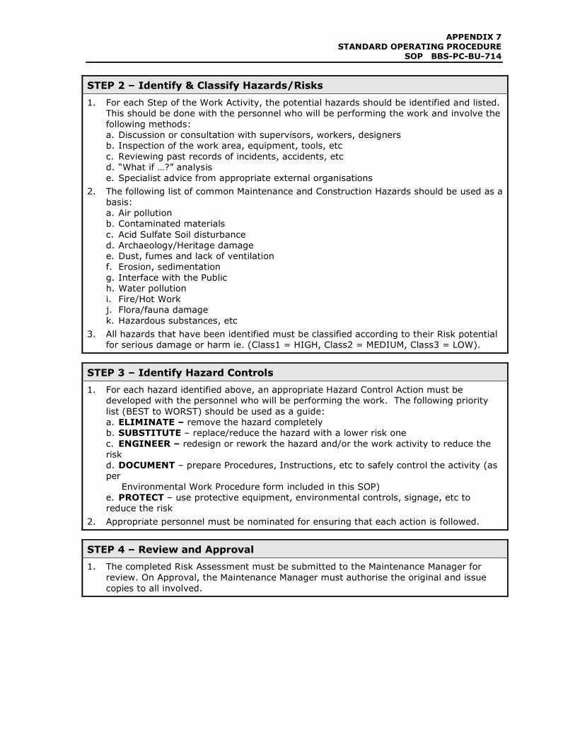
STEP 2 – Identify & Classify Hazards/Risks
1. For each Step of the Work Activity, the potential hazards should be identified and listed.
This should be done with the personnel who will be performing the work and involve the
following methods:
a. Discussion or consultation with supervisors, workers, designers
b. Inspection of the work area, equipment, tools, etc
c. Reviewing past records of incidents, accidents, etc
d. “What if …?” analysis
e. Specialist advice from appropriate external organisations
2. The following list of common Maintenance and Construction Hazards should be used as a
basis:
a. Air pollution
b. Contaminated materials
c. Acid Sulfate Soil disturbance
d. Archaeology/Heritage damage
e. Dust, fumes and lack of ventilation
f. Erosion, sedimentation
g. Interface with the Public
h. Water pollution
i. Fire/Hot Work
j. Flora/fauna damage
k. Hazardous substances, etc
3. All hazards that have been identified must be classified according to their Risk potential
for serious damage or harm ie. (Class1 = HIGH, Class2 = MEDIUM, Class3 = LOW).
STEP 3 – Identify Hazard Controls
1. For each hazard identified above, an appropriate Hazard Control Action must be
developed with the personnel who will be performing the work. The following priority
list (BEST to WORST) should be used as a guide:
a. ELIMINATE – remove the hazard completely
b. SUBSTITUTE – replace/reduce the hazard with a lower risk one
c. ENGINEER – redesign or rework the hazard and/or the work activity to reduce the
risk
d. DOCUMENT – prepare Procedures, Instructions, etc to safely control the activity (as
per
Environmental Work Procedure form included in this SOP)
e. PROTECT – use protective equipment, environmental controls, signage, etc to
reduce the risk
2. Appropriate personnel must be nominated for ensuring that each action is followed.
STEP 4 – Review and Approval
1. The completed Risk Assessment must be submitted to the Maintenance Manager for
review. On Approval, the Maintenance Manager must authorise the original and issue
copies to all involved.
APPENDIX 7
STANDARD OPERATING PROCEDURE SOP BBS-PC-BU-714
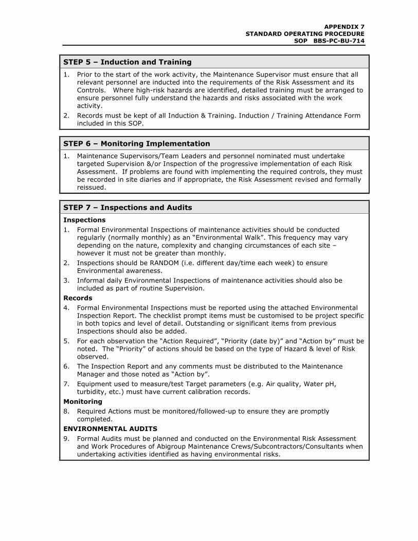
STEP 5 – Induction and Training
1. Prior to the start of the work activity, the Maintenance Supervisor must ensure that all
relevant personnel are inducted into the requirements of the Risk Assessment and its
Controls. Where high-risk hazards are identified, detailed training must be arranged to
ensure personnel fully understand the hazards and risks associated with the work
activity.
2. Records must be kept of all Induction & Training. Induction / Training Attendance Form
included in this SOP.
STEP 6 – Monitoring Implementation
1. Maintenance Supervisors/Team Leaders and personnel nominated must undertake
targeted Supervision &/or Inspection of the progressive implementation of each Risk
Assessment. If problems are found with implementing the required controls, they must
be recorded in site diaries and if appropriate, the Risk Assessment revised and formally
reissued.
STEP 7 – Inspections and Audits
Inspections
1. Formal Environmental Inspections of maintenance activities should be conducted
regularly (normally monthly) as an “Environmental Walk”. This frequency may vary
depending on the nature, complexity and changing circumstances of each site –
however it must not be greater than monthly.
2. Inspections should be RANDOM (i.e. different day/time each week) to ensure
Environmental awareness.
3. Informal daily Environmental Inspections of maintenance activities should also be
included as part of routine Supervision.
Records
4. Formal Environmental Inspections must be reported using the attached Environmental
Inspection Report. The checklist prompt items must be customised to be project specific
in both topics and level of detail. Outstanding or significant items from previous
Inspections should also be added.
5. For each observation the “Action Required”, “Priority (date by)” and “Action by” must be
noted. The “Priority” of actions should be based on the type of Hazard & level of Risk
observed.
6. The Inspection Report and any comments must be distributed to the Maintenance
Manager and those noted as “Action by”.
7. Equipment used to measure/test Target parameters (e.g. Air quality, Water pH,
turbidity, etc.) must have current calibration records.
Monitoring
8. Required Actions must be monitored/followed-up to ensure they are promptly
completed.
ENVIRONMENTAL AUDITS
9. Formal Audits must be planned and conducted on the Environmental Risk Assessment
and Work Procedures of Abigroup Maintenance Crews/Subcontractors/Consultants when
undertaking activities identified as having environmental risks.
APPENDIX 7
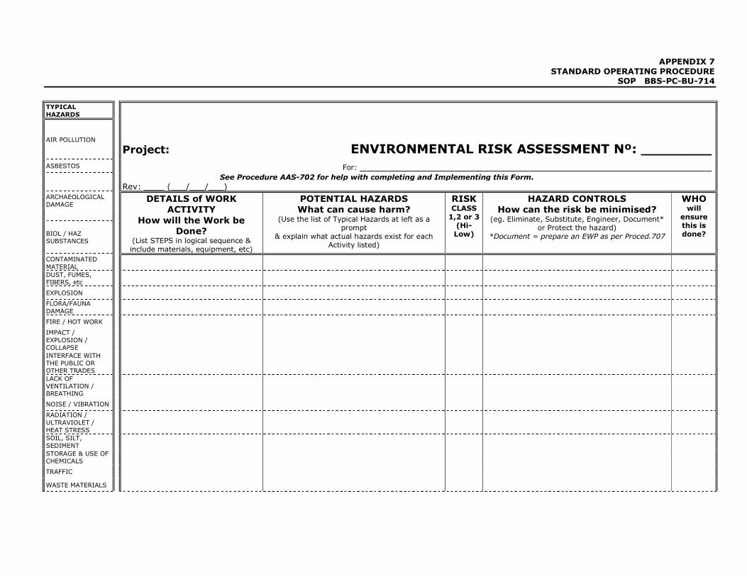
STANDARD OPERATING PROCEDURE SOP BBS-PC-BU-714
TYPICAL
HAZARDS
AIR POLLUTION
Project: ENVIRONMENTAL RISK ASSESSMENT Nº: ________ ASBESTOS For: ____________________________________________________
See Procedure AAS-702 for help with completing and Implementing this Form.
Rev: ____ (___/___/___) ARCHAEOLOGICAL
DAMAGE
BIOL / HAZ SUBSTANCES
DETAILS of WORK
ACTIVITY
How will the Work be
Done? (List STEPS in logical sequence & include materials, equipment, etc)
POTENTIAL HAZARDS
What can cause harm? (Use the list of Typical Hazards at left as a
prompt & explain what actual hazards exist for each
Activity listed)
RISK CLASS 1,2 or 3 (Hi-Low)
HAZARD CONTROLS
How can the risk be minimised? (eg. Eliminate, Substitute, Engineer, Document*
or Protect the hazard) *Document = prepare an EWP as per Proced.707
WHO will
ensure this is done?
CONTAMINATED
MATERIAL
DUST, FUMES, FIBERS, etc
EXPLOSION FLORA/FAUNA
DAMAGE
FIRE / HOT WORK IMPACT /
EXPLOSION / COLLAPSE
INTERFACE WITH
THE PUBLIC OR OTHER TRADES
LACK OF VENTILATION / BREATHING
NOISE / VIBRATION RADIATION /
ULTRAVIOLET /
HEAT STRESS
SOIL, SILT,
SEDIMENT
STORAGE & USE OF CHEMICALS
TRAFFIC WASTE MATERIALS
APPENDIX 7
STANDARD OPERATING PROCEDURE SOP BBS-PC-BU-714
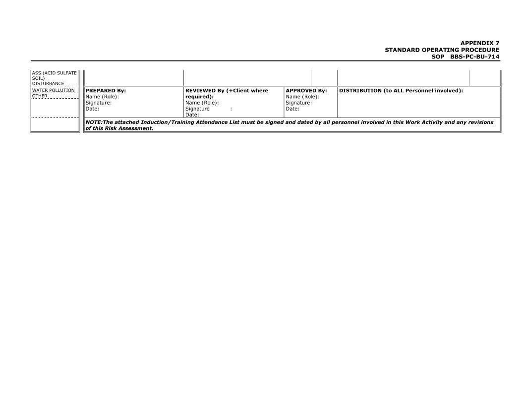
ASS (ACID SULFATE SOIL)
DISTURBANCE
WATER POLLUTION
OTHER
PREPARED By: Name (Role):
Signature: Date:
REVIEWED By (+Client where required):
Name (Role): Signature : Date:
APPROVED By: Name (Role):
Signature: Date:
DISTRIBUTION (to ALL Personnel involved):
NOTE:The attached Induction/Training Attendance List must be signed and dated by all personnel involved in this Work Activity and any revisions
of this Risk Assessment.

APPENDIX 7
STANDARD OPERATING PROCEDURE SOP BBS-PC-BU-714
ENVIRONMENTAL RISK ASSESSMENT Nº:
For ___________________Delivered By: _______________________
INDUCTION/TRAINING ATTENDANCE LIST No NAME (Please Print) Signature Company &
Position
Date
1.
2.
3.
4.
5.
6.
7.
8.
9.
10.
11.
12.
13.
14.
15.
16.
17.
18.
19.
20.
APPENDIX 7
STANDARD OPERATING PROCEDURE SOP BBS-PC-BU-714
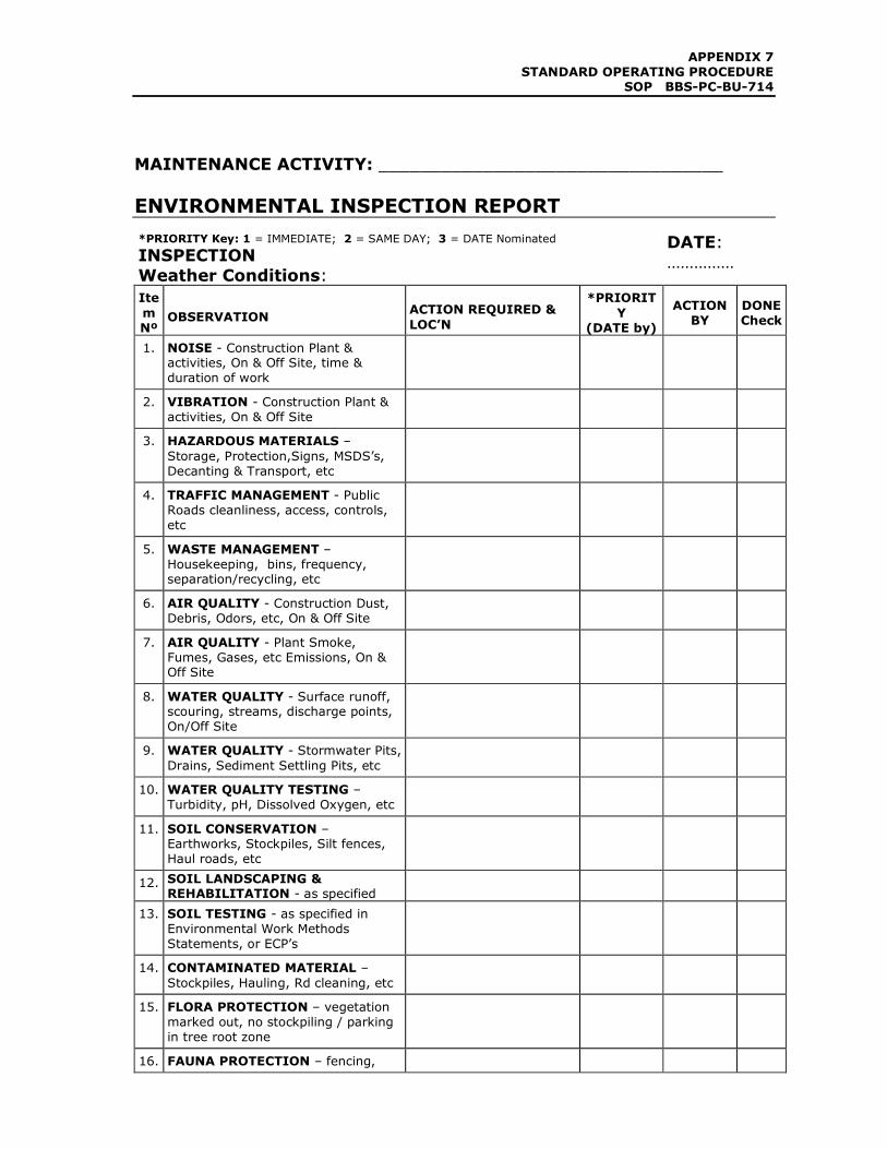
MAINTENANCE ACTIVITY: _________________________________
ENVIRONMENTAL INSPECTION REPORT
*PRIORITY Key: 1 = IMMEDIATE; 2 = SAME DAY; 3 = DATE Nominated
INSPECTION
Weather Conditions:
DATE:
……………
Ite
m
Nº OBSERVATION
ACTION REQUIRED &
LOC’N
*PRIORIT
Y
(DATE by)
ACTION
BY
DONE
Check
1. NOISE - Construction Plant & activities, On & Off Site, time &
duration of work
2. VIBRATION - Construction Plant &
activities, On & Off Site
3. HAZARDOUS MATERIALS –
Storage, Protection,Signs, MSDS’s,
Decanting & Transport, etc
4. TRAFFIC MANAGEMENT - Public
Roads cleanliness, access, controls,
etc
5. WASTE MANAGEMENT –
Housekeeping, bins, frequency, separation/recycling, etc
6. AIR QUALITY - Construction Dust,
Debris, Odors, etc, On & Off Site
7. AIR QUALITY - Plant Smoke,
Fumes, Gases, etc Emissions, On & Off Site
8. WATER QUALITY - Surface runoff, scouring, streams, discharge points,
On/Off Site
9. WATER QUALITY - Stormwater Pits,
Drains, Sediment Settling Pits, etc
10. WATER QUALITY TESTING –
Turbidity, pH, Dissolved Oxygen, etc
11. SOIL CONSERVATION – Earthworks, Stockpiles, Silt fences,
Haul roads, etc
12. SOIL LANDSCAPING & REHABILITATION - as specified
13. SOIL TESTING - as specified in
Environmental Work Methods
Statements, or ECP’s
14. CONTAMINATED MATERIAL –
Stockpiles, Hauling, Rd cleaning, etc
15. FLORA PROTECTION – vegetation
marked out, no stockpiling / parking
in tree root zone
16. FAUNA PROTECTION – fencing,
APPENDIX 7
STANDARD OPERATING PROCEDURE SOP BBS-PC-BU-714
*PRIORITY Key: 1 = IMMEDIATE; 2 = SAME DAY; 3 = DATE Nominated
INSPECTION
Weather Conditions:
DATE:
……………
Ite
m Nº
OBSERVATION ACTION REQUIRED &
LOC’N
*PRIORIT
Y (DATE by)
ACTION
BY
DONE
Check
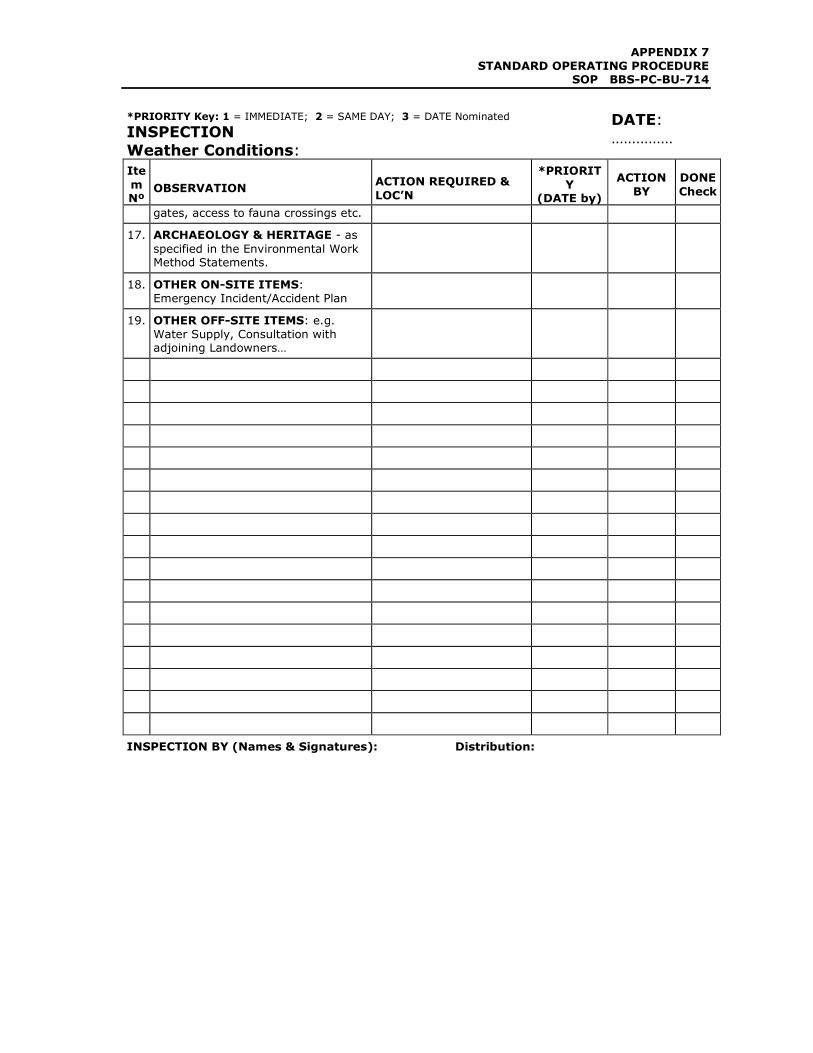
gates, access to fauna crossings etc.
17. ARCHAEOLOGY & HERITAGE - as
specified in the Environmental Work Method Statements.
18. OTHER ON-SITE ITEMS:
Emergency Incident/Accident Plan
19. OTHER OFF-SITE ITEMS: e.g.
Water Supply, Consultation with adjoining Landowners…
INSPECTION BY (Names & Signatures):
Distribution:
APPENDIX 7
STANDARD OPERATING PROCEDURE SOP BBS-PC-BU-714
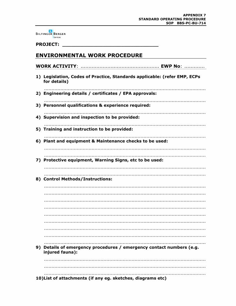
PROJECT: _______________________________
ENVIRONMENTAL WORK PROCEDURE
WORK ACTIVITY: .................................................. EWP No: .............
1) Legislation, Codes of Practice, Standards applicable: (refer EMP, ECPs for details)
............................................................................................................. 2) Engineering details / certificates / EPA approvals:
............................................................................................................. 3) Personnel qualifications & experience required:
............................................................................................................. 4) Supervision and inspection to be provided:
............................................................................................................. 5) Training and instruction to be provided:
............................................................................................................. 6) Plant and equipment & Maintenance checks to be used:
.............................................................................................................
............................................................................................................. 7) Protective equipment, Warning Signs, etc to be used:
.............................................................................................................
.............................................................................................................
8) Control Methods/Instructions:
.............................................................................................................
.............................................................................................................
.............................................................................................................
.............................................................................................................
.............................................................................................................
.............................................................................................................
.............................................................................................................
.............................................................................................................
.............................................................................................................
9) Details of emergency procedures / emergency contact numbers (e.g. injured fauna):
.............................................................................................................
.............................................................................................................
............................................................................................................. 10)List of attachments (if any eg. sketches, diagrams etc)

APPENDIX 7
STANDARD OPERATING PROCEDURE SOP BBS-PC-BU-714
.............................................................................................................
Prepared By: ....................... Reviewed By: .............. Approved By: .........
Signature: ........................... Signature: ................... Signature: ..............
Date: ................................... Date: ........................... Date: ......................
APPENDIX 7
STANDARD OPERATING PROCEDURE SOP BBS-PC-BU-715
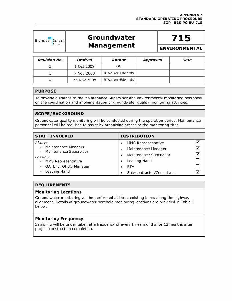
715
Groundwater
Management ENVIRONMENTAL
Revision No. Drafted Author Approved Date
2 6 Oct 2008 OC
3 7 Nov 2008 R Walker-Edwards
4 25 Nov 2008 R Walker-Edwards
PURPOSE
To provide guidance to the Maintenance Supervisor and environmental monitoring personnel
on the coordination and implementation of groundwater quality monitoring activities.
SCOPE/BACKGROUND
Groundwater quality monitoring will be conducted during the operation period. Maintenance
personnel will be required to assist by organising access to the monitoring sites.
STAFF INVOLVED DISTRIBUTION
Always
• Maintenance Manager
• Maintenance Supervisor
Possibly • MMS Representative
• QA, Env, OH&S Manager
• Leading Hand
• MMS Representative �
• Maintenance Manager �
• Maintenance Supervisor �
• Leading Hand �
• RTA �
• Sub-contractor/Consultant �
REQUIREMENTS
Monitoring Locations
Ground water monitoring will be performed at three existing bores along the highway
alignment. Details of groundwater borehole monitoring locations are provided in Table 1
below.
Monitoring Frequency
Sampling will be under taken at a frequency of every three months for 12 months after
project construction completion.
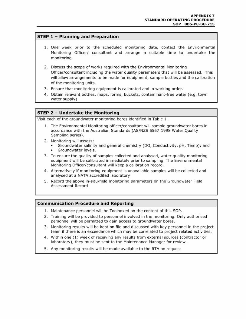
APPENDIX 7
STANDARD OPERATING PROCEDURE SOP BBS-PC-BU-715
STEP 1 – Planning and Preparation
1. One week prior to the scheduled monitoring date, contact the Environmental
Monitoring Officer/ consultant and arrange a suitable time to undertake the
monitoring.
2. Discuss the scope of works required with the Environmental Monitoring
Officer/consultant including the water quality parameters that will be assessed. This
will allow arrangements to be made for equipment, sample bottles and the calibration
of the monitoring units.
3. Ensure that monitoring equipment is calibrated and in working order.
4. Obtain relevant bottles, maps, forms, buckets, contaminant-free water (e.g. town
water supply)
STEP 2 – Undertake the Monitoring
Visit each of the groundwater monitoring bores identified in Table 1.
1. The Environmental Monitoring officer/consultant will sample groundwater bores in
accordance with the Australian Standards (AS/NZS 5567:1998 Water Quality
Sampling series).
2. Monitoring will assess:
• Groundwater salinity and general chemistry (DO, Conductivity, pH, Temp); and
• Groundwater levels.
3. To ensure the quality of samples collected and analysed, water quality monitoring
equipment will be calibrated immediately prior to sampling. The Environmental
Monitoring Officer/consultant will keep a calibration record.
4. Alternatively if monitoring equipment is unavailable samples will be collected and
analysed at a NATA accredited laboratory
5. Record the above in-situ/field monitoring parameters on the Groundwater Field
Assessment Record
Communication Procedure and Reporting
1. Maintenance personnel will be Toolboxed on the content of this SOP.
2. Training will be provided to personnel involved in the monitoring. Only authorised
personnel will be permitted to gain access to groundwater bores.
3. Monitoring results will be kept on file and discussed with key personnel in the project
team if there is an exceedance which may be correlated to project related activities.
4. Within one (1) week of receiving any results from external sources (contractor or
laboratory), they must be sent to the Maintenance Manager for review.
5. Any monitoring results will be made available to the RTA on request
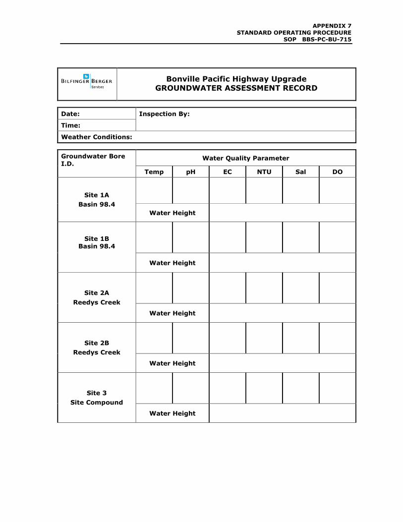
APPENDIX 7
STANDARD OPERATING PROCEDURE SOP BBS-PC-BU-715
Bonville Pacific Highway Upgrade
GROUNDWATER ASSESSMENT RECORD
Date:
Time:
Inspection By:
Weather Conditions:
Water Quality Parameter Groundwater Bore
I.D.
Temp pH EC NTU Sal DO
Site 1A
Basin 98.4
Water Height
Site 1B
Basin 98.4
Water Height
Site 2A
Reedys Creek
Water Height
Site 2B
Reedys Creek
Water Height
Site 3
Site Compound
Water Height
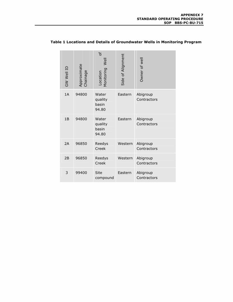
APPENDIX 7
STANDARD OPERATING PROCEDURE SOP BBS-PC-BU-715
Table 1 Locations and Details of Groundwater Wells in Monitoring Program
GW W
ell ID
Approximate
Chainage
Location
of
Monitoring Well
Side of Alignment
Owner of well
1A 94800 Water
quality
basin
94.80
Eastern Abigroup
Contractors
1B 94800 Water
quality
basin
94.80
Eastern Abigroup
Contractors
2A 96850 Reedys
Creek
Western Abigroup
Contractors
2B 96850 Reedys
Creek
Western Abigroup
Contractors
3 99400 Site
compound
Eastern Abigroup
Contractors

APPENDIX 7 STANDARD OPERATING PROCEDURE
SOP BBS-PC-BU-715


![Operating Procedures 1 G2 - OPERATING PROCEDURES [6 Exam Questions - 6 Groups] G2APhone operating procedures; USB/LSB utilization conventions; procedural](https://img.pdfslide.net/doc/110x75/56649e4d5503460f94b4351a/operating-procedures-1-g2-operating-procedures-6-exam-questions-6-groups.jpg)