Embed Size (px)
Citation preview
Independence Series Mtgh/SC 1 SPR_IND ALL_R4.xlsx
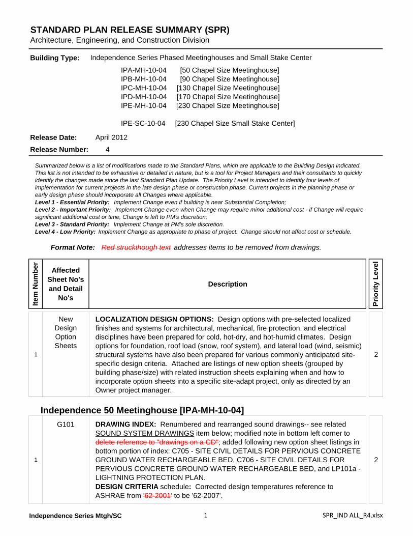
STANDARD PLAN RELEASE SUMMARY (SPR)Architecture, Engineering, and Construction Division
Item
Num
ber
Affected Sheet No's and Detail
No's
Description
Prio
rity
Leve
l
1
NewDesign Option Sheets
LOCALIZATION DESIGN OPTIONS: Design options with pre-selected localized finishes and systems for architectural, mechanical, fire protection, and electrical disciplines have been prepared for cold, hot-dry, and hot-humid climates. Design options for foundation, roof load (snow, roof system), and lateral load (wind, seismic) structural systems have also been prepared for various commonly anticipated site-specific design criteria. Attached are listings of new option sheets (grouped by building phase/size) with related instruction sheets explaining when and how to incorporate option sheets into a specific site-adapt project, only as directed by an Owner project manager.
2
Independence 50 Meetinghouse [IPA-MH-10-04]
1
G101 DRAWING INDEX: Renumbered and rearranged sound drawings-- see related SOUND SYSTEM DRAWINGS item below; modified note in bottom left corner to delete reference to "drawings on a CD"; added following new option sheet listings in bottom portion of index: C705 - SITE CIVIL DETAILS FOR PERVIOUS CONCRETE GROUND WATER RECHARGEABLE BED, C706 - SITE CIVIL DETAILS FOR PERVIOUS CONCRETE GROUND WATER RECHARGEABLE BED, and LP101a - LIGHTNING PROTECTION PLAN.DESIGN CRITERIA schedule: Corrected design temperatures reference to ASHRAE from '62-2001' to be '62-2007'.
2
Release Number: 4
Summarized below is a list of modifications made to the Standard Plans, which are applicable to the Building Design indicated. This list is not intended to be exhaustive or detailed in nature, but is a tool for Project Managers and their consultants to quickly identify the changes made since the last Standard Plan Update. The Priority Level is intended to identify four levels of implementation for current projects in the late design phase or construction phase. Current projects in the planning phase or early design phase should incorporate all Changes where applicable.Level 1 - Essential Priority: Implement Change even if building is near Substantial Completion;Level 2 - Important Priority: Implement Change even when Change may require minor additional cost - if Change will require significant additional cost or time, Change is left to PM's discretion;Level 3 - Standard Priority: Implement Change at PM's sole discretion.Level 4 - Low Priority: Implement Change as appropriate to phase of project. Change should not affect cost or schedule.
Format Note: Red struckthough text addresses items to be removed from drawings.
Building Type: Independence Series Phased Meetinghouses and Small Stake Center
IPA-MH-10-04 [50 Chapel Size Meetinghouse]IPB-MH-10-04 [90 Chapel Size Meetinghouse]IPC-MH-10-04 [130 Chapel Size Meetinghouse]IPD-MH-10-04 [170 Chapel Size Meetinghouse]IPE-MH-10-04 [230 Chapel Size Meetinghouse]
IPE-SC-10-04 [230 Chapel Size Small Stake Center]
Release Date: April 2012
Independence Series Mtgh/SC 2 SPR_IND ALL_R4.xlsx
Item
Num
ber
Affected Sheet No's and Detail
No's
Description
Prio
rity
Leve
l
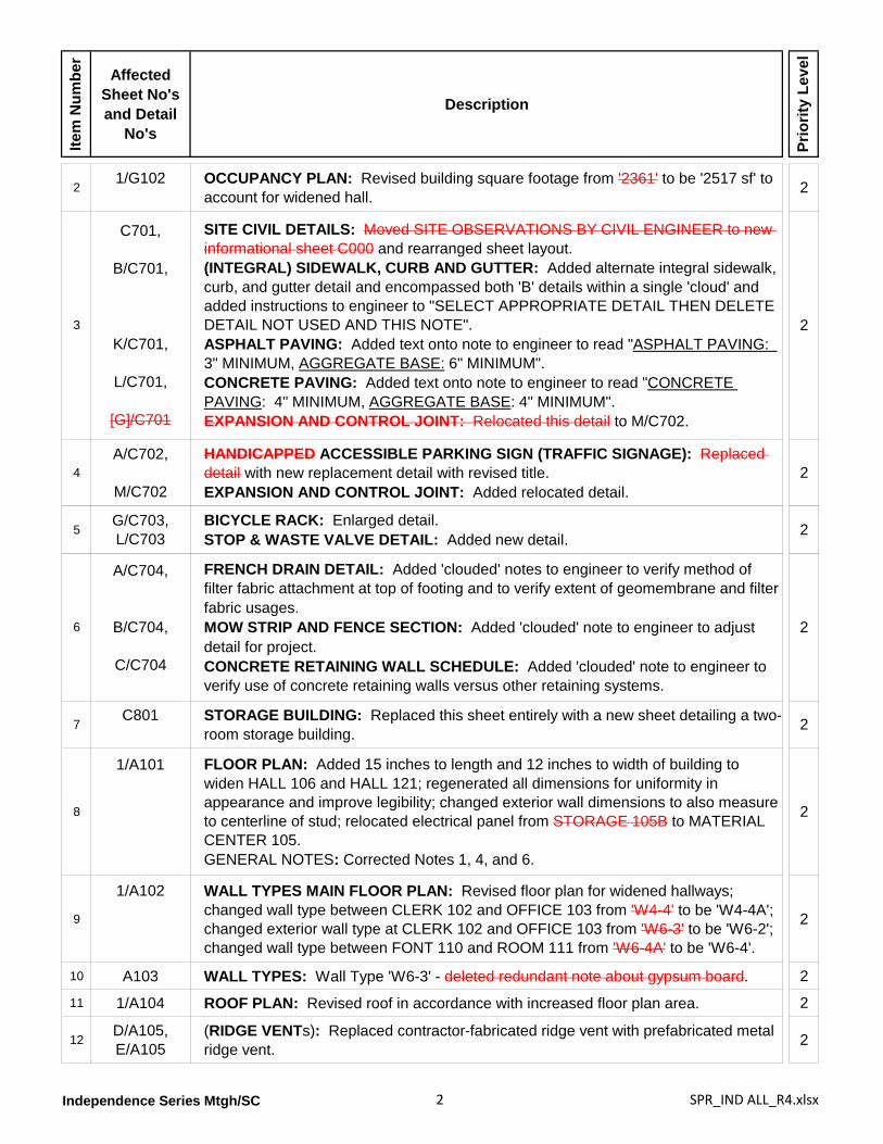
21/G102 OCCUPANCY PLAN: Revised building square footage from '2361' to be '2517 sf' to
account for widened hall. 2
3
C701,
B/C701,
K/C701,
L/C701,
[G]/C701
SITE CIVIL DETAILS: Moved SITE OBSERVATIONS BY CIVIL ENGINEER to new informational sheet C000 and rearranged sheet layout.(INTEGRAL) SIDEWALK, CURB AND GUTTER: Added alternate integral sidewalk, curb, and gutter detail and encompassed both 'B' details within a single 'cloud' and added instructions to engineer to "SELECT APPROPRIATE DETAIL THEN DELETE DETAIL NOT USED AND THIS NOTE".ASPHALT PAVING: Added text onto note to engineer to read "ASPHALT PAVING: 3" MINIMUM, AGGREGATE BASE: 6" MINIMUM".CONCRETE PAVING: Added text onto note to engineer to read "CONCRETE PAVING: 4" MINIMUM, AGGREGATE BASE: 4" MINIMUM".EXPANSION AND CONTROL JOINT: Relocated this detail to M/C702.
2
4A/C702,
M/C702
HANDICAPPED ACCESSIBLE PARKING SIGN (TRAFFIC SIGNAGE): Replaced detail with new replacement detail with revised title.EXPANSION AND CONTROL JOINT: Added relocated detail.
2
5G/C703,L/C703
BICYCLE RACK: Enlarged detail.STOP & WASTE VALVE DETAIL: Added new detail. 2
6
A/C704,
B/C704,
C/C704
FRENCH DRAIN DETAIL: Added 'clouded' notes to engineer to verify method of filter fabric attachment at top of footing and to verify extent of geomembrane and filter fabric usages.MOW STRIP AND FENCE SECTION: Added 'clouded' note to engineer to adjust detail for project.CONCRETE RETAINING WALL SCHEDULE: Added 'clouded' note to engineer to verify use of concrete retaining walls versus other retaining systems.
2
7C801 STORAGE BUILDING: Replaced this sheet entirely with a new sheet detailing a two-
room storage building. 2
8
1/A101 FLOOR PLAN: Added 15 inches to length and 12 inches to width of building to widen HALL 106 and HALL 121; regenerated all dimensions for uniformity in appearance and improve legibility; changed exterior wall dimensions to also measure to centerline of stud; relocated electrical panel from STORAGE 105B to MATERIAL CENTER 105.GENERAL NOTES: Corrected Notes 1, 4, and 6.
2
9
1/A102 WALL TYPES MAIN FLOOR PLAN: Revised floor plan for widened hallways; changed wall type between CLERK 102 and OFFICE 103 from 'W4-4' to be 'W4-4A'; changed exterior wall type at CLERK 102 and OFFICE 103 from 'W6-3' to be 'W6-2'; changed wall type between FONT 110 and ROOM 111 from 'W6-4A' to be 'W6-4'.
2
10 A103 WALL TYPES: Wall Type 'W6-3' - deleted redundant note about gypsum board. 2
11 1/A104 ROOF PLAN: Revised roof in accordance with increased floor plan area. 2
12D/A105,E/A105
(RIDGE VENTs): Replaced contractor-fabricated ridge vent with prefabricated metal ridge vent. 2
Independence Series Mtgh/SC 3 SPR_IND ALL_R4.xlsx
Item
Num
ber
Affected Sheet No's and Detail
No's
Description
Prio
rity
Leve
l
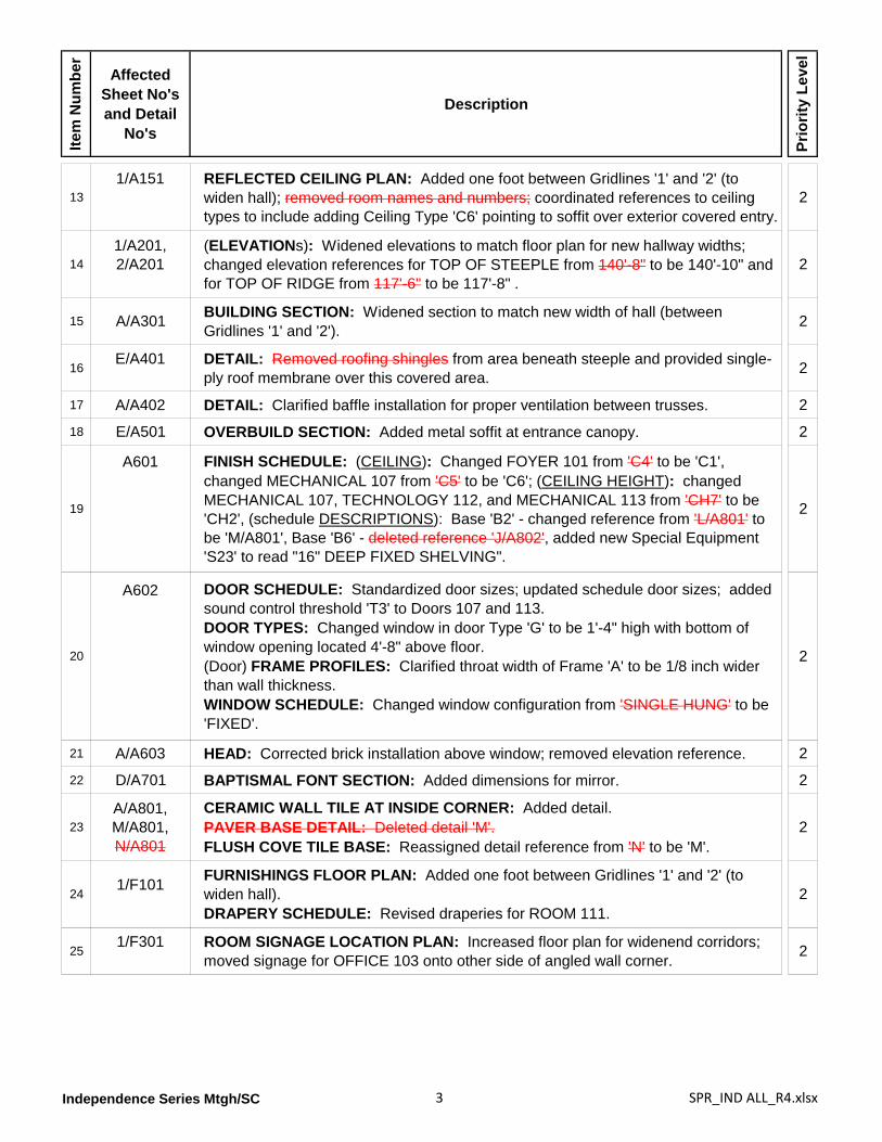
131/A151 REFLECTED CEILING PLAN: Added one foot between Gridlines '1' and '2' (to
widen hall); removed room names and numbers; coordinated references to ceiling types to include adding Ceiling Type 'C6' pointing to soffit over exterior covered entry.
2
141/A201,2/A201
(ELEVATIONs): Widened elevations to match floor plan for new hallway widths; changed elevation references for TOP OF STEEPLE from 140'-8" to be 140'-10" and for TOP OF RIDGE from 117'-6" to be 117'-8" .
2
15 A/A301 BUILDING SECTION: Widened section to match new width of hall (between Gridlines '1' and '2'). 2
16E/A401 DETAIL: Removed roofing shingles from area beneath steeple and provided single-
ply roof membrane over this covered area. 2
17 A/A402 DETAIL: Clarified baffle installation for proper ventilation between trusses. 2
18 E/A501 OVERBUILD SECTION: Added metal soffit at entrance canopy. 2
19
A601 FINISH SCHEDULE: (CEILING): Changed FOYER 101 from 'C4' to be 'C1', changed MECHANICAL 107 from 'C5' to be 'C6'; (CEILING HEIGHT): changed MECHANICAL 107, TECHNOLOGY 112, and MECHANICAL 113 from 'CH7' to be 'CH2', (schedule DESCRIPTIONS): Base 'B2' - changed reference from 'L/A801' to be 'M/A801', Base 'B6' - deleted reference 'J/A802', added new Special Equipment 'S23' to read "16" DEEP FIXED SHELVING".
2
20
A602 DOOR SCHEDULE: Standardized door sizes; updated schedule door sizes; added sound control threshold 'T3' to Doors 107 and 113.DOOR TYPES: Changed window in door Type 'G' to be 1'-4" high with bottom of window opening located 4'-8" above floor.(Door) FRAME PROFILES: Clarified throat width of Frame 'A' to be 1/8 inch wider than wall thickness.WINDOW SCHEDULE: Changed window configuration from 'SINGLE HUNG' to be 'FIXED'.
2
21 A/A603 HEAD: Corrected brick installation above window; removed elevation reference. 2
22 D/A701 BAPTISMAL FONT SECTION: Added dimensions for mirror. 2
23A/A801,M/A801,N/A801
CERAMIC WALL TILE AT INSIDE CORNER: Added detail.PAVER BASE DETAIL: Deleted detail 'M'.FLUSH COVE TILE BASE: Reassigned detail reference from 'N' to be 'M'.
2
241/F101 FURNISHINGS FLOOR PLAN: Added one foot between Gridlines '1' and '2' (to
widen hall).DRAPERY SCHEDULE: Revised draperies for ROOM 111.
2
251/F301 ROOM SIGNAGE LOCATION PLAN: Increased floor plan for widenend corridors;
moved signage for OFFICE 103 onto other side of angled wall corner. 2
Independence Series Mtgh/SC 4 SPR_IND ALL_R4.xlsx
Item
Num
ber
Affected Sheet No's and Detail
No's
Description
Prio
rity
Leve
l
26
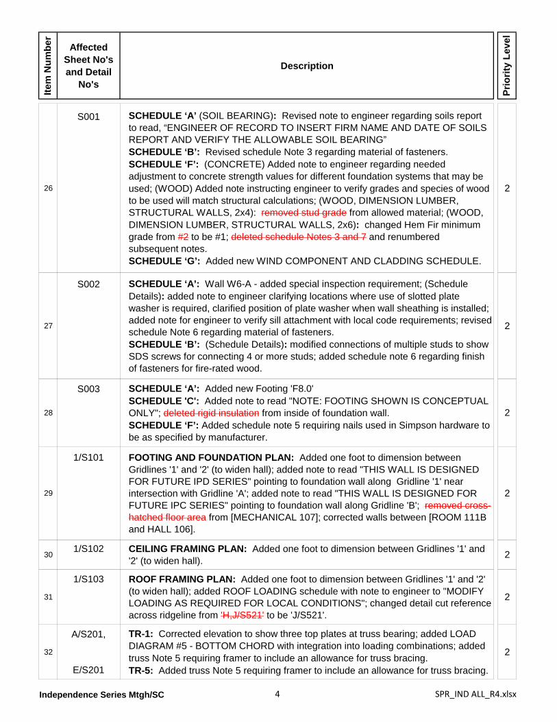
S001 SCHEDULE ‘A’ (SOIL BEARING): Revised note to engineer regarding soils report to read, “ENGINEER OF RECORD TO INSERT FIRM NAME AND DATE OF SOILS REPORT AND VERIFY THE ALLOWABLE SOIL BEARING”SCHEDULE ‘B’: Revised schedule Note 3 regarding material of fasteners.SCHEDULE ‘F’: (CONCRETE) Added note to engineer regarding needed adjustment to concrete strength values for different foundation systems that may be used; (WOOD) Added note instructing engineer to verify grades and species of wood to be used will match structural calculations; (WOOD, DIMENSION LUMBER, STRUCTURAL WALLS, 2x4): removed stud grade from allowed material; (WOOD, DIMENSION LUMBER, STRUCTURAL WALLS, 2x6): changed Hem Fir minimum grade from #2 to be #1; deleted schedule Notes 3 and 7 and renumbered subsequent notes.SCHEDULE ‘G’: Added new WIND COMPONENT AND CLADDING SCHEDULE.
2
27
S002 SCHEDULE ‘A’: Wall W6-A - added special inspection requirement; (Schedule Details): added note to engineer clarifying locations where use of slotted plate washer is required, clarified position of plate washer when wall sheathing is installed; added note for engineer to verify sill attachment with local code requirements; revised schedule Note 6 regarding material of fasteners.SCHEDULE ‘B’: (Schedule Details): modified connections of multiple studs to show SDS screws for connecting 4 or more studs; added schedule note 6 regarding finish of fasteners for fire-rated wood.
2
28
S003 SCHEDULE ‘A’: Added new Footing 'F8.0'SCHEDULE 'C': Added note to read "NOTE: FOOTING SHOWN IS CONCEPTUAL ONLY"; deleted rigid insulation from inside of foundation wall.SCHEDULE ‘F’: Added schedule note 5 requiring nails used in Simpson hardware to be as specified by manufacturer.
2
29
1/S101 FOOTING AND FOUNDATION PLAN: Added one foot to dimension between Gridlines '1' and '2' (to widen hall); added note to read "THIS WALL IS DESIGNED FOR FUTURE IPD SERIES" pointing to foundation wall along Gridline '1' near intersection with Gridline 'A'; added note to read "THIS WALL IS DESIGNED FOR FUTURE IPC SERIES" pointing to foundation wall along Gridline 'B'; removed cross-hatched floor area from [MECHANICAL 107]; corrected walls between [ROOM 111B and HALL 106].
2
301/S102 CEILING FRAMING PLAN: Added one foot to dimension between Gridlines '1' and
'2' (to widen hall). 2
31
1/S103 ROOF FRAMING PLAN: Added one foot to dimension between Gridlines '1' and '2' (to widen hall); added ROOF LOADING schedule with note to engineer to "MODIFY LOADING AS REQUIRED FOR LOCAL CONDITIONS"; changed detail cut reference across ridgeline from 'H,J/S521' to be 'J/S521'.
2
32
A/S201,
E/S201
TR-1: Corrected elevation to show three top plates at truss bearing; added LOAD DIAGRAM #5 - BOTTOM CHORD with integration into loading combinations; added truss Note 5 requiring framer to include an allowance for truss bracing.TR-5: Added truss Note 5 requiring framer to include an allowance for truss bracing.
2
Independence Series Mtgh/SC 5 SPR_IND ALL_R4.xlsx
Item
Num
ber
Affected Sheet No's and Detail
No's
Description
Prio
rity
Leve
l
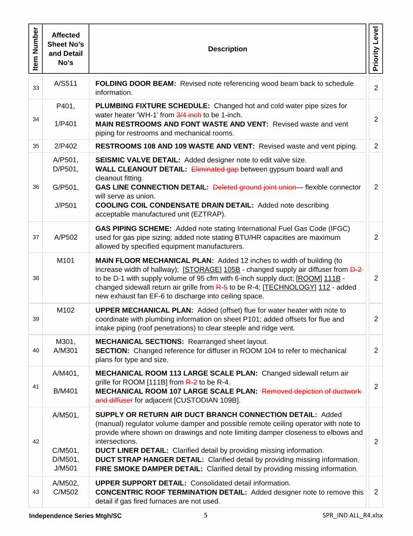
33A/S511 FOLDING DOOR BEAM: Revised note referencing wood beam back to schedule
information. 2
34
P401,
1/P401
PLUMBING FIXTURE SCHEDULE: Changed hot and cold water pipe sizes for water heater 'WH-1' from 3/4 inch to be 1-inch.MAIN RESTROOMS AND FONT WASTE AND VENT: Revised waste and vent piping for restrooms and mechanical rooms.
2
35 2/P402 RESTROOMS 108 AND 109 WASTE AND VENT: Revised waste and vent piping. 2
36
A/P501,D/P501,
G/P501,
J/P501
SEISMIC VALVE DETAIL: Added designer note to edit valve size.WALL CLEANOUT DETAIL: Eliminated gap between gypsum board wall and cleanout fitting.GAS LINE CONNECTION DETAIL: Deleted ground joint union— flexible connector will serve as union.COOLING COIL CONDENSATE DRAIN DETAIL: Added note describing acceptable manufactured unit (EZTRAP).
2
37 A/P502GAS PIPING SCHEME: Added note stating International Fuel Gas Code (IFGC) used for gas pipe sizing; added note stating BTU/HR capacities are maximum allowed by specified equipment manufacturers.
2
38
M101 MAIN FLOOR MECHANICAL PLAN: Added 12 inches to width of building (to increase width of hallway); [STORAGE] 105B - changed supply air diffuser from D-2 to be D-1 with supply volume of 95 cfm with 6-inch supply duct; [ROOM] 111B - changed sidewall return air grille from R-5 to be R-4; [TECHNOLOGY] 112 - added new exhaust fan EF-6 to discharge into ceiling space.
2
39M102 UPPER MECHANICAL PLAN: Added (offset) flue for water heater with note to
coordinate with plumbing information on sheet P101; added offsets for flue and intake piping (roof penetrations) to clear steeple and ridge vent.
2
40M301,
A/M301MECHANICAL SECTIONS: Rearranged sheet layout.SECTION: Changed reference for diffuser in ROOM 104 to refer to mechanical plans for type and size.
2
41
A/M401,
B/M401
MECHANICAL ROOM 113 LARGE SCALE PLAN: Changed sidewall return air grille for ROOM [111B] from R-2 to be R-4.MECHANICAL ROOM 107 LARGE SCALE PLAN: Removed depiction of ductwork and diffuser for adjacent [CUSTODIAN 109B].
2
42
A/M501,
C/M501,D/M501,J/M501
SUPPLY OR RETURN AIR DUCT BRANCH CONNECTION DETAIL: Added (manual) regulator volume damper and possible remote ceiling operator with note to provide where shown on drawings and note limiting damper closeness to elbows and intersections.DUCT LINER DETAIL: Clarified detail by providing missing information.DUCT STRAP HANGER DETAIL: Clarified detail by providing missing information.FIRE SMOKE DAMPER DETAIL: Clarified detail by providing missing information.
2
43A/M502,C/M502
UPPER SUPPORT DETAIL: Consolidated detail information.CONCENTRIC ROOF TERMINATION DETAIL: Added designer note to remove this detail if gas fired furnaces are not used.
2
Independence Series Mtgh/SC 6 SPR_IND ALL_R4.xlsx
Item
Num
ber
Affected Sheet No's and Detail
No's
Description
Prio
rity
Leve
l
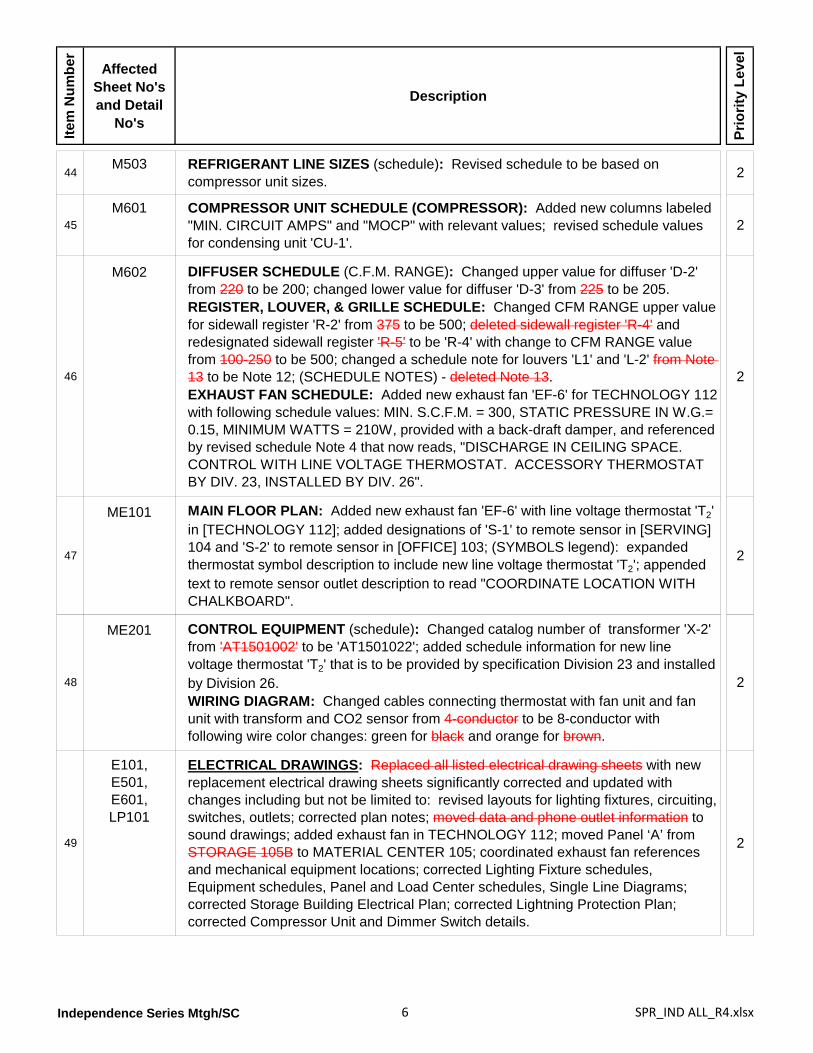
44M503 REFRIGERANT LINE SIZES (schedule): Revised schedule to be based on
compressor unit sizes. 2
45M601 COMPRESSOR UNIT SCHEDULE (COMPRESSOR): Added new columns labeled
"MIN. CIRCUIT AMPS" and "MOCP" with relevant values; revised schedule values for condensing unit 'CU-1'.
2
46
M602 DIFFUSER SCHEDULE (C.F.M. RANGE): Changed upper value for diffuser 'D-2' from 220 to be 200; changed lower value for diffuser 'D-3' from 225 to be 205.REGISTER, LOUVER, & GRILLE SCHEDULE: Changed CFM RANGE upper value for sidewall register 'R-2' from 375 to be 500; deleted sidewall register 'R-4' and redesignated sidewall register 'R-5' to be 'R-4' with change to CFM RANGE value from 100-250 to be 500; changed a schedule note for louvers 'L1' and 'L-2' from Note 13 to be Note 12; (SCHEDULE NOTES) - deleted Note 13.EXHAUST FAN SCHEDULE: Added new exhaust fan 'EF-6' for TECHNOLOGY 112 with following schedule values: MIN. S.C.F.M. = 300, STATIC PRESSURE IN W.G.= 0.15, MINIMUM WATTS = 210W, provided with a back-draft damper, and referenced by revised schedule Note 4 that now reads, "DISCHARGE IN CEILING SPACE. CONTROL WITH LINE VOLTAGE THERMOSTAT. ACCESSORY THERMOSTAT BY DIV. 23, INSTALLED BY DIV. 26".
2
47
ME101 MAIN FLOOR PLAN: Added new exhaust fan 'EF-6' with line voltage thermostat 'T2' in [TECHNOLOGY 112]; added designations of 'S-1' to remote sensor in [SERVING] 104 and 'S-2' to remote sensor in [OFFICE] 103; (SYMBOLS legend): expanded thermostat symbol description to include new line voltage thermostat 'T2'; appended text to remote sensor outlet description to read "COORDINATE LOCATION WITH CHALKBOARD".
2
48
ME201 CONTROL EQUIPMENT (schedule): Changed catalog number of transformer 'X-2' from 'AT1501002' to be 'AT1501022'; added schedule information for new line voltage thermostat 'T2' that is to be provided by specification Division 23 and installed by Division 26.WIRING DIAGRAM: Changed cables connecting thermostat with fan unit and fan unit with transform and CO2 sensor from 4-conductor to be 8-conductor with following wire color changes: green for black and orange for brown.
2
49
E101,E501,E601,LP101
ELECTRICAL DRAWINGS: Replaced all listed electrical drawing sheets with new replacement electrical drawing sheets significantly corrected and updated with changes including but not be limited to: revised layouts for lighting fixtures, circuiting, switches, outlets; corrected plan notes; moved data and phone outlet information to sound drawings; added exhaust fan in TECHNOLOGY 112; moved Panel ‘A’ from STORAGE 105B to MATERIAL CENTER 105; coordinated exhaust fan references and mechanical equipment locations; corrected Lighting Fixture schedules, Equipment schedules, Panel and Load Center schedules, Single Line Diagrams; corrected Storage Building Electrical Plan; corrected Lightning Protection Plan; corrected Compressor Unit and Dimmer Switch details.
2
Independence Series Mtgh/SC 7 SPR_IND ALL_R4.xlsx
Item
Num
ber
Affected Sheet No's and Detail
No's
Description
Prio
rity
Leve
l
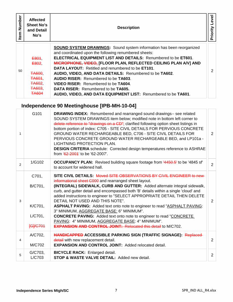
50
E801,E802,
TA600,TA601,TA602,TA603,TA604
SOUND SYSTEM DRAWINGS: Sound system information has been reorganized and coordinated upon the following renumbered sheets:ELECTRICAL EQUIPMENT LIST AND DETAILS: Renumbered to be ET601.MICROPHONE, VIDEO, [FLOOR PLAN, REFLECTED CEILING PLAN A/V] AND DATA LAYOUT: Retitled and renumbered to be ET101.AUDIO, VIDEO, AND DATA DETAILS: Renumbered to be TA602.AUDIO RISER: Renumbered to be TA603.VIDEO RISER: Renumbered to be TA604.DATA RISER: Renumbered to be TA605.AUDIO, VIDEO, AND DATA EQUIPMENT LIST: Renumbered to be TA601.
2
Independence 90 Meetinghouse [IPB-MH-10-04]
1
G101
DRAWING INDEX: Renumbered and rearranged sound drawings-- see related SOUND SYSTEM DRAWINGS item below; modified note in bottom left corner to delete reference to "drawings on a CD"; clarified following option sheet listings in bottom portion of index: C705 - SITE CIVIL DETAILS FOR PERVIOUS CONCRETE GROUND WATER RECHARGEABLE BED, C706 - SITE CIVIL DETAILS FOR PERVIOUS CONCRETE GROUND WATER RECHARGEABLE BED, and LP101a - LIGHTNING PROTECTION PLAN.DESIGN CRITERIA schedule: Corrected design temperatures reference to ASHRAE from '62-2001' to be '62-2007'.
2
21/G102 OCCUPANCY PLAN: Revised building square footage from '4450.5' to be '4845 sf'
to account for widened hall. 2
3
C701,
B/C701,
K/C701,
L/C701,
[G]/C701
SITE CIVIL DETAILS: Moved SITE OBSERVATIONS BY CIVIL ENGINEER to new informational sheet C000 and rearranged sheet layout.(INTEGRAL) SIDEWALK, CURB AND GUTTER: Added alternate integral sidewalk, curb, and gutter detail and encompassed both 'B' details within a single 'cloud' and added instructions to engineer to "SELECT APPROPRIATE DETAIL THEN DELETE DETAIL NOT USED AND THIS NOTE".ASPHALT PAVING: Added text onto note to engineer to read "ASPHALT PAVING: 3" MINIMUM, AGGREGATE BASE: 6" MINIMUM".CONCRETE PAVING: Added text onto note to engineer to read "CONCRETE PAVING: 4" MINIMUM, AGGREGATE BASE: 4" MINIMUM".EXPANSION AND CONTROL JOINT: Relocated this detail to M/C702.
2
4A/C702,
M/C702
HANDICAPPED ACCESSIBLE PARKING SIGN (TRAFFIC SIGNAGE): Replaced detail with new replacement detail.EXPANSION AND CONTROL JOINT: Added relocated detail.
2
5G/C703,L/C703
BICYCLE RACK: Enlarged detail.STOP & WASTE VALVE DETAIL: Added new detail. 2
Independence Series Mtgh/SC 8 SPR_IND ALL_R4.xlsx
Item
Num
ber
Affected Sheet No's and Detail
No's
Description
Prio
rity
Leve
l
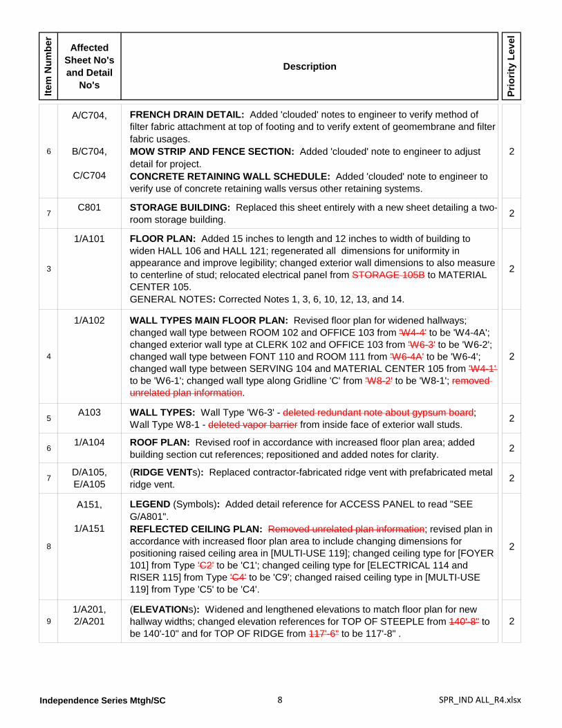
6
A/C704,
B/C704,
C/C704
FRENCH DRAIN DETAIL: Added 'clouded' notes to engineer to verify method of filter fabric attachment at top of footing and to verify extent of geomembrane and filter fabric usages.MOW STRIP AND FENCE SECTION: Added 'clouded' note to engineer to adjust detail for project.CONCRETE RETAINING WALL SCHEDULE: Added 'clouded' note to engineer to verify use of concrete retaining walls versus other retaining systems.
2
7C801 STORAGE BUILDING: Replaced this sheet entirely with a new sheet detailing a two-
room storage building. 2
3
1/A101 FLOOR PLAN: Added 15 inches to length and 12 inches to width of building to widen HALL 106 and HALL 121; regenerated all dimensions for uniformity in appearance and improve legibility; changed exterior wall dimensions to also measure to centerline of stud; relocated electrical panel from STORAGE 105B to MATERIAL CENTER 105.GENERAL NOTES: Corrected Notes 1, 3, 6, 10, 12, 13, and 14.
2
4
1/A102 WALL TYPES MAIN FLOOR PLAN: Revised floor plan for widened hallways; changed wall type between ROOM 102 and OFFICE 103 from 'W4-4' to be 'W4-4A'; changed exterior wall type at CLERK 102 and OFFICE 103 from 'W6-3' to be 'W6-2'; changed wall type between FONT 110 and ROOM 111 from 'W6-4A' to be 'W6-4'; changed wall type between SERVING 104 and MATERIAL CENTER 105 from 'W4-1' to be 'W6-1'; changed wall type along Gridline 'C' from 'W8-2' to be 'W8-1'; removed unrelated plan information.
2
5A103 WALL TYPES: Wall Type 'W6-3' - deleted redundant note about gypsum board;
Wall Type W8-1 - deleted vapor barrier from inside face of exterior wall studs. 2
61/A104 ROOF PLAN: Revised roof in accordance with increased floor plan area; added
building section cut references; repositioned and added notes for clarity. 2
7D/A105,E/A105
(RIDGE VENTs): Replaced contractor-fabricated ridge vent with prefabricated metal ridge vent. 2
8
A151,
1/A151
LEGEND (Symbols): Added detail reference for ACCESS PANEL to read "SEE G/A801".REFLECTED CEILING PLAN: Removed unrelated plan information; revised plan in accordance with increased floor plan area to include changing dimensions for positioning raised ceiling area in [MULTI-USE 119]; changed ceiling type for [FOYER 101] from Type 'C2' to be 'C1'; changed ceiling type for [ELECTRICAL 114 and RISER 115] from Type 'C4' to be 'C9'; changed raised ceiling type in [MULTI-USE 119] from Type 'C5' to be 'C4'.
2
91/A201,2/A201
(ELEVATIONs): Widened and lengthened elevations to match floor plan for new hallway widths; changed elevation references for TOP OF STEEPLE from 140'-8" to be 140'-10" and for TOP OF RIDGE from 117'-6" to be 117'-8" .
2
Independence Series Mtgh/SC 9 SPR_IND ALL_R4.xlsx
Item
Num
ber
Affected Sheet No's and Detail
No's
Description
Prio
rity
Leve
l
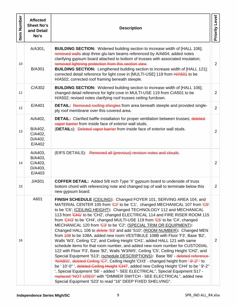
10
A/A301,
B/A301
BUILDING SECTION: Widened building section to increase width of [HALL 106]; removed walls atop three glu-lam beams referenced by A/A604; added notes clarifying gypsum board attached to bottom of trusses with associated insulation; removed lightning protection from this section view.BUILDING SECTION: Lengthened building section to increase width of [HALL 121]; corrected detail reference for light cove in [MULTI-USE] 119 from H/A501 to be H/A502; corrected roof framing beneath steeple.
2
11C/A302 BUILDING SECTION: Widened building section to increase width of [HALL 106];
changed detail reference for light cove in MULTI-USE 119 from C/A501 to be H/A502; revised notes clarifying roof trusses ceiling furrdown.
2
12E/A401 DETAIL: Removed roofing shingles from area beneath steeple and provided single-
ply roof membrane over this covered area. 2
13
A/A402,
B/A402,C/A402,D/A402,E/A402
DETAIL: Clarified baffle installation for proper ventilation between trusses; deleted vapor barrier from inside face of exterior wall studs.(DETAILs): Deleted vapor barrier from inside face of exterior wall studs. 2
14
A/A403,B/A403,C/A403,D/A403,E/A403
(EIFS DETAILS): Removed all (previous) revision notes and clouds.
2
15J/A501 COFFER DETAIL: Added 5/8 inch Type 'X' gypsum board to underside of truss
bottom chord with referencing note and changed top of wall to terminate below this new gypsum board.
2
16
A601 FINISH SCHEDULE (CEILING): Changed FOYER 101, SERVING AREA 104, and MATERIAL CENTER 105 from 'C2' to be 'C1', changed MECHANICAL 107 from 'C5' to be 'C6'; (CEILING HEIGHT): Changed TECHNOLOGY 112 and MECHANICAL 113 from 'CH1' to be 'CH2', changed ELECTRICAL 114 and FIRE RISER ROOM 115 from 'CH3' to be 'CH4', changed MULTI-USE 119 from 'C5' to be 'C4', changed MECHANICAL 120 from 'C3' to be 'C2'; (SPECIAL TRIM OR EQUIPMENT): Changed HALL 106 to delete 'S3' and add 'S10'; (ROOM NUMBER): Changed MEN from 108 to be 108A, added new room VESTIBULE 108B with Floor 'F3', Base 'B2', Walls 'W3', Ceiling 'C2', and Ceiling Height 'CH1', added HALL 121 with same schedule items for that room number, and added new room number for CUSTODIAL 122 with Floor 'F3', Base 'B2', Walls 'W3/W5', Ceiling 'C5', Ceiling Height 'CH2', and Special Equipment 'S13'; (schedule DESCRIPTIONS): Base 'B6' - deleted reference 'N/A801', deleted Ceiling 'C7', Ceiling Height 'CH3' - changed height from ' 9'-2" ' to be ' 10'-0" ', deleted Ceiling Height 'CH7', added new Ceiling Height 'CH4' to be ' 9'-2" ', Special Equipment 'S6' - added "- SEE ELECTRICAL", Special Equipment S17 - replaced "NOT USED" with "DIMMER SWITCH - SEE ELECTRICAL", added new Special Equipment 'S23' to read "16" DEEP FIXED SHELVING".
2
Independence Series Mtgh/SC 10 SPR_IND ALL_R4.xlsx
Item
Num
ber
Affected Sheet No's and Detail
No's
Description
Prio
rity
Leve
l
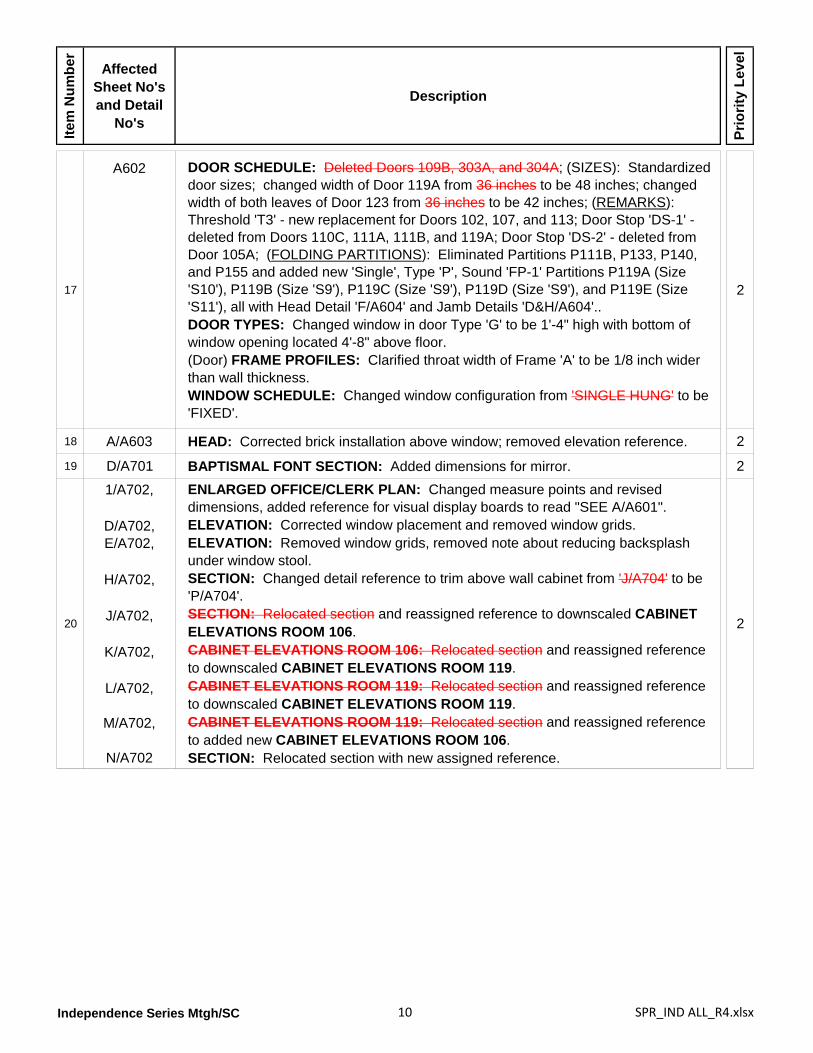
17
A602 DOOR SCHEDULE: Deleted Doors 109B, 303A, and 304A; (SIZES): Standardized door sizes; changed width of Door 119A from 36 inches to be 48 inches; changed width of both leaves of Door 123 from 36 inches to be 42 inches; (REMARKS): Threshold 'T3' - new replacement for Doors 102, 107, and 113; Door Stop 'DS-1' - deleted from Doors 110C, 111A, 111B, and 119A; Door Stop 'DS-2' - deleted from Door 105A; (FOLDING PARTITIONS): Eliminated Partitions P111B, P133, P140, and P155 and added new 'Single', Type 'P', Sound 'FP-1' Partitions P119A (Size 'S10'), P119B (Size 'S9'), P119C (Size 'S9'), P119D (Size 'S9'), and P119E (Size 'S11'), all with Head Detail 'F/A604' and Jamb Details 'D&H/A604'..DOOR TYPES: Changed window in door Type 'G' to be 1'-4" high with bottom of window opening located 4'-8" above floor.(Door) FRAME PROFILES: Clarified throat width of Frame 'A' to be 1/8 inch wider than wall thickness.WINDOW SCHEDULE: Changed window configuration from 'SINGLE HUNG' to be 'FIXED'.
2
18 A/A603 HEAD: Corrected brick installation above window; removed elevation reference. 2
19 D/A701 BAPTISMAL FONT SECTION: Added dimensions for mirror. 2
20
1/A702,X
D/A702,E/A702,
XH/A702,
XJ/A702,
XK/A702,
XL/A702,
XM/A702,
XN/A702
ENLARGED OFFICE/CLERK PLAN: Changed measure points and revised dimensions, added reference for visual display boards to read "SEE A/A601".ELEVATION: Corrected window placement and removed window grids.ELEVATION: Removed window grids, removed note about reducing backsplash under window stool.SECTION: Changed detail reference to trim above wall cabinet from 'J/A704' to be 'P/A704'.SECTION: Relocated section and reassigned reference to downscaled CABINET ELEVATIONS ROOM 106.CABINET ELEVATIONS ROOM 106: Relocated section and reassigned reference to downscaled CABINET ELEVATIONS ROOM 119.CABINET ELEVATIONS ROOM 119: Relocated section and reassigned reference to downscaled CABINET ELEVATIONS ROOM 119.CABINET ELEVATIONS ROOM 119: Relocated section and reassigned reference to added new CABINET ELEVATIONS ROOM 106.SECTION: Relocated section with new assigned reference.
2
Independence Series Mtgh/SC 11 SPR_IND ALL_R4.xlsx
Item
Num
ber
Affected Sheet No's and Detail
No's
Description
Prio
rity
Leve
l
21
1/A703,
2/A703,
A/A703,B/A703,C/A703,D/A703,E/A703,
XF/A703,
XG/A703,
XH/A703
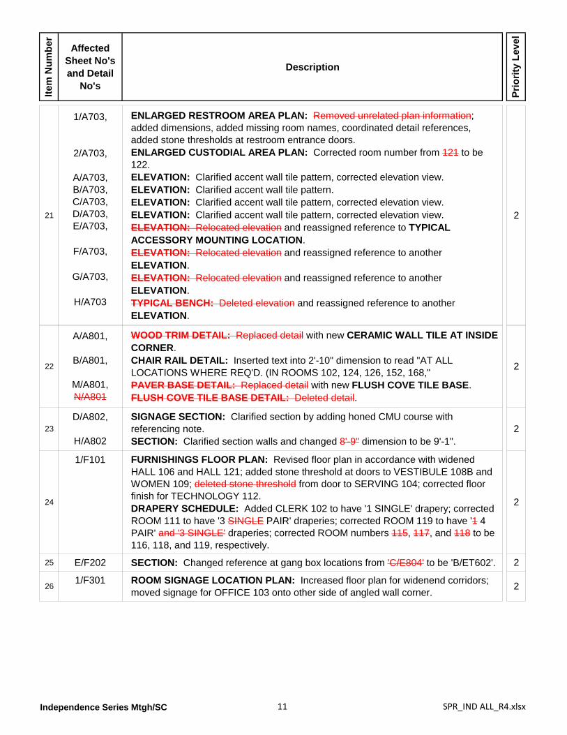
ENLARGED RESTROOM AREA PLAN: Removed unrelated plan information; added dimensions, added missing room names, coordinated detail references, added stone thresholds at restroom entrance doors.ENLARGED CUSTODIAL AREA PLAN: Corrected room number from 121 to be 122.ELEVATION: Clarified accent wall tile pattern, corrected elevation view.ELEVATION: Clarified accent wall tile pattern.ELEVATION: Clarified accent wall tile pattern, corrected elevation view.ELEVATION: Clarified accent wall tile pattern, corrected elevation view.ELEVATION: Relocated elevation and reassigned reference to TYPICAL ACCESSORY MOUNTING LOCATION.ELEVATION: Relocated elevation and reassigned reference to another ELEVATION.ELEVATION: Relocated elevation and reassigned reference to another ELEVATION.TYPICAL BENCH: Deleted elevation and reassigned reference to another ELEVATION.
2
22
A/A801,
B/A801,
M/A801,N/A801
WOOD TRIM DETAIL: Replaced detail with new CERAMIC WALL TILE AT INSIDE CORNER.CHAIR RAIL DETAIL: Inserted text into 2'-10" dimension to read "AT ALL LOCATIONS WHERE REQ'D. (IN ROOMS 102, 124, 126, 152, 168,"PAVER BASE DETAIL: Replaced detail with new FLUSH COVE TILE BASE.FLUSH COVE TILE BASE DETAIL: Deleted detail.
2
23D/A802,
H/A802
SIGNAGE SECTION: Clarified section by adding honed CMU course with referencing note.SECTION: Clarified section walls and changed 8'-9" dimension to be 9'-1".
2
24
1/F101 FURNISHINGS FLOOR PLAN: Revised floor plan in accordance with widened HALL 106 and HALL 121; added stone threshold at doors to VESTIBULE 108B and WOMEN 109; deleted stone threshold from door to SERVING 104; corrected floor finish for TECHNOLOGY 112.DRAPERY SCHEDULE: Added CLERK 102 to have '1 SINGLE' drapery; corrected ROOM 111 to have '3 SINGLE PAIR' draperies; corrected ROOM 119 to have '1 4 PAIR' and '3 SINGLE' draperies; corrected ROOM numbers 115, 117, and 118 to be 116, 118, and 119, respectively.
2
25 E/F202 SECTION: Changed reference at gang box locations from 'C/E804' to be 'B/ET602'. 2
261/F301 ROOM SIGNAGE LOCATION PLAN: Increased floor plan for widenend corridors;
moved signage for OFFICE 103 onto other side of angled wall corner. 2
Independence Series Mtgh/SC 12 SPR_IND ALL_R4.xlsx
Item
Num
ber
Affected Sheet No's and Detail
No's
Description
Prio
rity
Leve
l
27
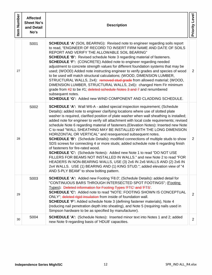
S001 SCHEDULE ‘A’ (SOIL BEARING): Revised note to engineer regarding soils report to read, “ENGINEER OF RECORD TO INSERT FIRM NAME AND DATE OF SOILS REPORT AND VERIFY THE ALLOWABLE SOIL BEARING”SCHEDULE ‘B’: Revised schedule Note 3 regarding material of fasteners.SCHEDULE ‘F’: (CONCRETE) Added note to engineer regarding needed adjustment to concrete strength values for different foundation systems that may be used; (WOOD) Added note instructing engineer to verify grades and species of wood to be used will match structural calculations; (WOOD, DIMENSION LUMBER, STRUCTURAL WALLS, 2x4): removed stud grade from allowed material; (WOOD, DIMENSION LUMBER, STRUCTURAL WALLS, 2x6): changed Hem Fir minimum grade from #2 to be #1; deleted schedule Notes 3 and 7 and renumbered subsequent notes.SCHEDULE ‘G’: Added new WIND COMPONENT AND CLADDING SCHEDULE.
2
28
S002 SCHEDULE ‘A’: Wall W6-A - added special inspection requirement; (Schedule Details): added note to engineer clarifying locations where use of slotted plate washer is required, clarified position of plate washer when wall sheathing is installed; added note for engineer to verify sill attachment with local code requirements; revised schedule Note 6 regarding material of fasteners.(Elevation Notes): Inserted new Note C to read "WALL SHEATHING MAY BE INSTALLED WITH THE LONG DIMENSION HORIZONTAL OR VERTICAL" and resequenced subsequent notes.SCHEDULE ‘B’: (Schedule Details): modified connections of multiple studs to show SDS screws for connecting 4 or more studs; added schedule note 6 regarding finish of fasteners for fire-rated wood.SCHEDULE 'C': (Schedule Notes): Added new Note 1 to read "DO NOT USE FILLERS FOR BEAMS NOT INSTALLED IN WALLS." and new Note 2 to read "FOR HEADERS IN NON-BEARING WALLS, USE (3) 2x6 IN 2x6 WALLS AND (2) 2x6 IN 2x4 WALLS. USE (1) BEARING AND (1) KING STUD."; added elevation view of "4 AND 5-PLY BEAM" to show bolting pattern.
2
29
S003 SCHEDULE ‘A’: Added new Footing 'F8.0'; (Schedule Details): added detail for "CONTINUOUS BARS THROUGH INTERSECTED SPOT FOOTINGS"; (Footing Types): Deleted information for Footing Types 'FTC' and 'FTS'.SCHEDULE 'C': Added note to read "NOTE: FOOTING SHOWN IS CONCEPTUAL ONLY"; deleted rigid insulation from inside of foundation wall.SCHEDULE ‘F’: Added schedule Note 3 (defining fastener materials), Note 4 (reducing nail penetration depth into sheating), and Note 5 (requiring nails used in Simpson hardware to be as specified by manufacturer).
2
30S004 SCHEDULE 'A': (Schedule Notes): Inserted minor text into Notes 1 and 2; added
new Note 9 regarding basis of 'HDU8' capacities. 2
Independence Series Mtgh/SC 13 SPR_IND ALL_R4.xlsx
Item
Num
ber
Affected Sheet No's and Detail
No's
Description
Prio
rity
Leve
l
31
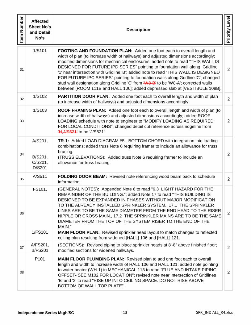
1/S101 FOOTING AND FOUNDATION PLAN: Added one foot each to overall length and width of plan (to increase width of hallways) and adjusted dimensions accordingly; modified dimensions for mechanical enclosures; added note to read "THIS WALL IS DESIGNED FOR FUTURE IPD SERIES" pointing to foundation wall along Gridline '1' near intersection with Gridline 'B'; added note to read "THIS WALL IS DESIGNED FOR FUTURE IPC SERIES" pointing to foundation walls along Gridline 'C'; changed stud wall designation along Gridline 'C' from 'W8-B' to be 'W8-A'; corrected walls between [ROOM 111B and HALL 106]; added depressed slab at [VESTIBULE 108B].
2
321/S102 PARTITION DOOR PLAN: Added one foot each to overall length and width of plan
(to increase width of hallways) and adjusted dimensions accordingly. 2
33
1/S103 ROOF FRAMING PLAN: Added one foot each to overall length and width of plan (to increase width of hallways) and adjusted dimensions accordingly; added ROOF LOADING schedule with note to engineer to "MODIFY LOADING AS REQUIRED FOR LOCAL CONDITIONS"; changed detail cut reference across ridgeline from 'H,J/S521' to be 'J/S521'.
2
34
A/S201,
B/S201,C/S201,D/S201
TR-1: Added LOAD DIAGRAM #5 - BOTTOM CHORD with integration into loading combinations; added truss Note 6 requiring framer to include an allowance for truss bracing.(TRUSS ELEVATIONS): Added truss Note 6 requiring framer to include an allowance for truss bracing.
2
35A/S511 FOLDING DOOR BEAM: Revised note referencing wood beam back to schedule
information. 2
36
FS101,
1/FS101
(GENERAL NOTES): Appended Note 6 to read "6.3 LIGHT HAZARD FOR THE REMAINDER OF THE BUILDING."; added Note 17 to read "THIS BUILDING IS DESIGNED TO BE EXPANDED IN PHASES WITHOUT MAJOR MODIFICATION TO THE ALREADY INSTALLED SPRINKLER SYSTEM., 17.1 THE SPRINKLER LINES ARE TO BE THE SAME DIAMETER FROM THE END HEAD TO THE RISER NIPPLE OR CROSS MAIN., 17.2 THE SPRINKLER MAINS ARE TO BE THE SAME DIAMETER FROM THE TOP OF THE SYSTEM RISER TO THE END OF THE MAIN."MAIN FLOOR PLAN: Revised sprinkler head layout to match changes to reflected ceiling plan resulting from widened [HALL] 106 and [HALL] 121.
2
37A/FS201,B/FS201
(SECTIONS): Revised piping to place sprinkler heads at 8'-8" above finished floor; modified sections for widened hallways. 2
38
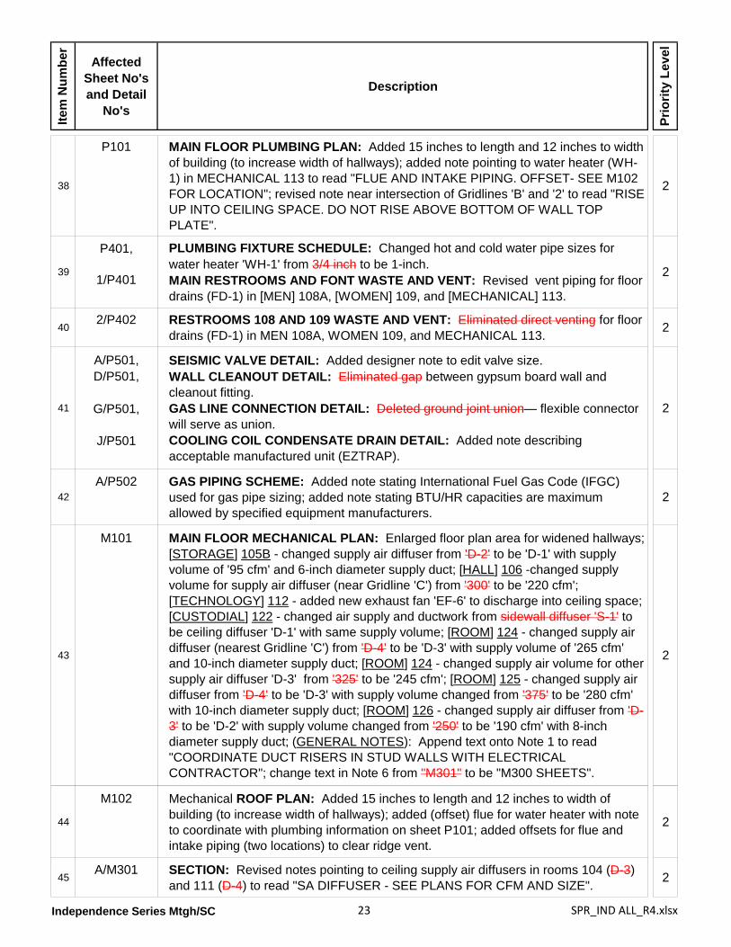
P101 MAIN FLOOR PLUMBING PLAN: Revised plan to add one foot each to overall length and width to increase width of HALL 106 and HALL 121; added note pointing to water heater (WH-1) in MECHANICAL 113 to read "FLUE AND INTAKE PIPING. OFFSET- SEE M102 FOR LOCATION"; revised note near intersection of Gridlines 'B' and '2' to read "RISE UP INTO CEILING SPACE. DO NOT RISE ABOVE BOTTOM OF WALL TOP PLATE".
2
Independence Series Mtgh/SC 14 SPR_IND ALL_R4.xlsx
Item
Num
ber
Affected Sheet No's and Detail
No's
Description
Prio
rity
Leve
l
39
P401,
1/P401
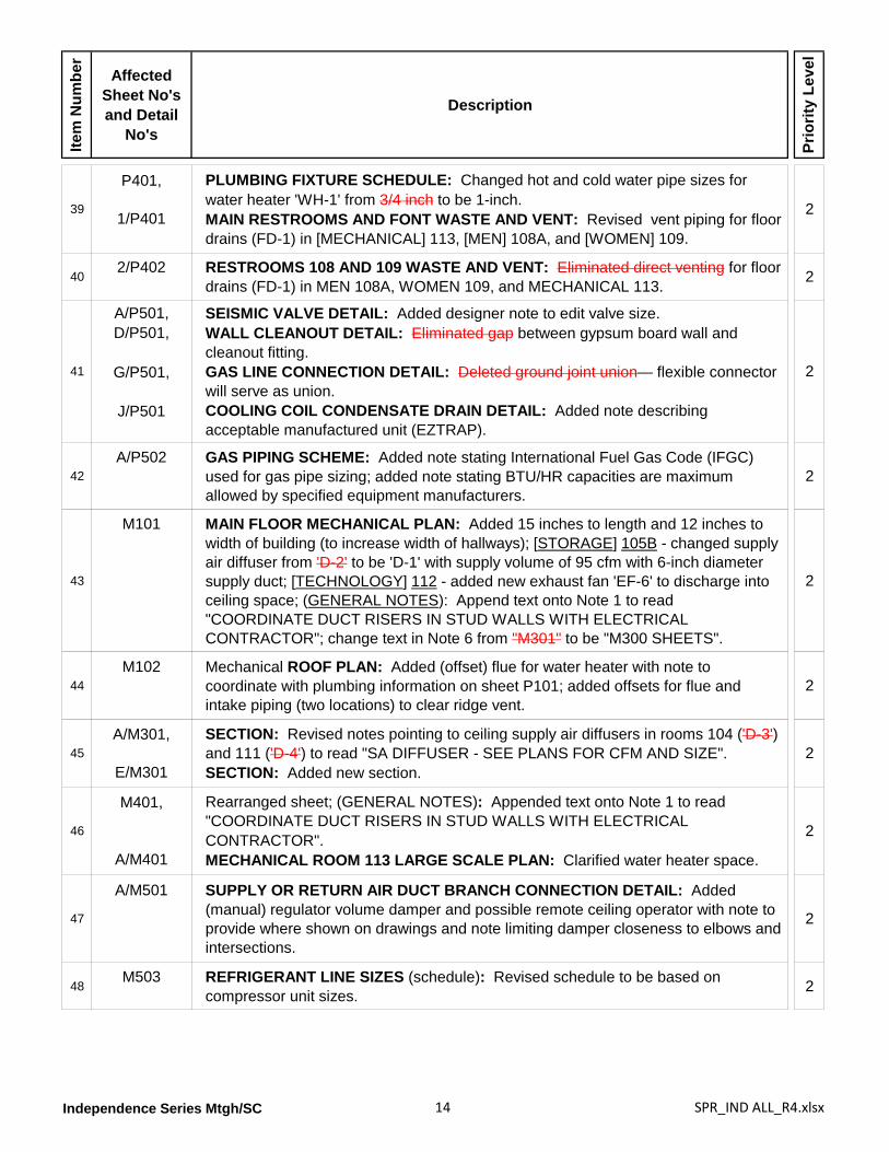
PLUMBING FIXTURE SCHEDULE: Changed hot and cold water pipe sizes for water heater 'WH-1' from 3/4 inch to be 1-inch.MAIN RESTROOMS AND FONT WASTE AND VENT: Revised vent piping for floor drains (FD-1) in [MECHANICAL] 113, [MEN] 108A, and [WOMEN] 109.
2
402/P402 RESTROOMS 108 AND 109 WASTE AND VENT: Eliminated direct venting for floor
drains (FD-1) in MEN 108A, WOMEN 109, and MECHANICAL 113. 2
41
A/P501,D/P501,
G/P501,
J/P501
SEISMIC VALVE DETAIL: Added designer note to edit valve size.WALL CLEANOUT DETAIL: Eliminated gap between gypsum board wall and cleanout fitting.GAS LINE CONNECTION DETAIL: Deleted ground joint union— flexible connector will serve as union.COOLING COIL CONDENSATE DRAIN DETAIL: Added note describing acceptable manufactured unit (EZTRAP).
2
42A/P502 GAS PIPING SCHEME: Added note stating International Fuel Gas Code (IFGC)
used for gas pipe sizing; added note stating BTU/HR capacities are maximum allowed by specified equipment manufacturers.
2
43
M101 MAIN FLOOR MECHANICAL PLAN: Added 15 inches to length and 12 inches to width of building (to increase width of hallways); [STORAGE] 105B - changed supply air diffuser from 'D-2' to be 'D-1' with supply volume of 95 cfm with 6-inch diameter supply duct; [TECHNOLOGY] 112 - added new exhaust fan 'EF-6' to discharge into ceiling space; (GENERAL NOTES): Append text onto Note 1 to read "COORDINATE DUCT RISERS IN STUD WALLS WITH ELECTRICAL CONTRACTOR"; change text in Note 6 from "M301" to be "M300 SHEETS".
2
44M102 Mechanical ROOF PLAN: Added (offset) flue for water heater with note to
coordinate with plumbing information on sheet P101; added offsets for flue and intake piping (two locations) to clear ridge vent.
2
45A/M301,
E/M301
SECTION: Revised notes pointing to ceiling supply air diffusers in rooms 104 ('D-3') and 111 ('D-4') to read "SA DIFFUSER - SEE PLANS FOR CFM AND SIZE".SECTION: Added new section.
2
46
M401,
A/M401
Rearranged sheet; (GENERAL NOTES): Appended text onto Note 1 to read "COORDINATE DUCT RISERS IN STUD WALLS WITH ELECTRICAL CONTRACTOR".MECHANICAL ROOM 113 LARGE SCALE PLAN: Clarified water heater space.
2
47
A/M501 SUPPLY OR RETURN AIR DUCT BRANCH CONNECTION DETAIL: Added (manual) regulator volume damper and possible remote ceiling operator with note to provide where shown on drawings and note limiting damper closeness to elbows and intersections.
2
48M503 REFRIGERANT LINE SIZES (schedule): Revised schedule to be based on
compressor unit sizes. 2
Independence Series Mtgh/SC 15 SPR_IND ALL_R4.xlsx
Item
Num
ber
Affected Sheet No's and Detail
No's
Description
Prio
rity
Leve
l
49
M601 FAN UNIT SCHEDULE (GAS FIRED FURNACE) schedule: Changed "MIN. OUTSIDE AIR CFM" schedule values for fan units 'F-1' and 'F-3' from 375 and 730 to be 370 and 735, respectively.COMPRESSOR UNIT SCHEDULE (COMPRESSOR): Added new columns labeled "MIN. CIRCUIT AMPS" and "MOCP" with relevant values; revised multiple schedule values for condensing unit 'CU-1', 'CU-2', and 'CU-4'.DX COIL SCHEDULE: Significantly changed schedule values for all (direct expansion) condenser coils.ENERGY RECOVERY VENTILATOR schedule: Added new schedule Note 3 to reference schedule MARK and read "ENERGY RECOVERY VENTILATOR MARKS CORRESPOND WITH FAN UNIT MARKS".
2
50
M602 DIFFUSER SCHEDULE (C.F.M. RANGE): Changed upper value for diffuser 'D-2' from 220 to be 200; changed lower value for diffuser 'D-3' from 225 to be 205; added new diffuser 'D-5' with following schedule values: CFM RANGE = 505-600 (schedule Note 2), DIFFUSER SIZE = 15x15, NECK CONN. 14-inch diameter, BLOW = 4 WAY, PATTERN = same as 'D-4', A (%) = 25, and B(%) = 25.REGISTER, LOUVER, & GRILLE SCHEDULE: Changed CFM RANGE upper value for sidewall register 'R-2' from 375 to be 500; changed nominal size of register 'R-4' from 30x30 to be 30x28; changed CFM RANGE for louver 'L-1' from 1755 to be 1710; (SCHEDULE NOTES) - deleted Note 12.EXHAUST FAN SCHEDULE: Added new exhaust fan 'EF-6' for TECHNOLOGY 112 with following schedule values: MIN. S.C.F.M. = 300, STATIC PRESSURE IN W.G.= 0.15, MINIMUM WATTS = 210W, provided with a back-draft damper, and referenced by revised schedule Note 4 that now reads, "DISCHARGE IN CEILING SPACE. CONTROL WITH LINE VOLTAGE THERMOSTAT. ACCESSORY THERMOSTAT BY DIV. 23, INSTALLED BY DIV. 26".
2
51
ME101 MAIN FLOOR PLAN: Added new exhaust fan 'EF-6' with line voltage thermostat 'T2' in [TECHNOLOGY 112]; added designations of 'S-1' to remote sensor in [SERVING] 104 and 'S-2' to remote sensor in [OFFICE] 103; (SYMBOLS legend): expanded thermostat symbol description to include new line voltage thermostat 'T2'; appended text to remote sensor outlet description to read "COORDINATE LOCATION WITH CHALKBOARD".
2
52
ME201,
A/ME201
CONTROL EQUIPMENT (schedule): Changed catalog number of transformer 'X-2' from "AT150F1002" to be "AT150F1022"; added schedule information for new line voltage thermostat 'T2' to be provided by specification Division 23 and installed by Division 26; added schedule information for new smoke relay 'SR' to be 30 AMP 120V COIL, catalog number 'DP2030B5003" with new schedule Note 3 to read "PROVIDE ENCLOSURE".WIRING DIAGRAM: Changed (top) cable connecting thermostat 'T-1' with fan unit from 4 conductor to be 8 conductor cable with wire colors changed from black to green and from brown to orange; combined two 4 conductor cables connecting transformer 'X-2' and fan unit with CO2 sensor into one 8-conductor cable with wire colors changed from black to green and from brown to orange.ENERGY RECOVERY VENTILATOR WIRING: Combined white and blue wires connecting damper motors 'DM-1' or 'DM-2' with energy recovery ventilator into one 4 conductor cable; removed note regarding 'F-7' and 'F-9' systems.
2
Independence Series Mtgh/SC 16 SPR_IND ALL_R4.xlsx
Item
Num
ber
Affected Sheet No's and Detail
No's
Description
Prio
rity
Leve
l
53
E101,E501,E601,
FA101,LP101
ELECTRICAL DRAWINGS: Replaced all listed electrical drawing sheets with new replacement electrical drawing sheets significantly corrected and updated with changes including but not be limited to: revised layouts for lighting fixtures, circuiting, switches, outlets; corrected plan notes; moved data and phone outlet information to sound drawings; added exhaust fan in TECHNOLOGY 112; moved Panel ‘A’ to from STORAGE 105B to MATERIAL CENTER 105; coordinated exhaust fan references and mechanical equipment locations; corrected Lighting Fixture schedules, Equipment schedules, Panel and Load Center schedules, Single Line Diagrams, and Fire Riser Diagrams; corrected Storage Building Electrical Plan; corrected Lightning Protection Plan; corrected Compressor Unit and Dimmer Switch details.
2
54
E801,E802,
TA600,TA601,TA602,TA603,TA604
SOUND SYSTEM DRAWINGS: Sound system information has been reorganized and coordinated upon the following renumbered sheets:ELECTRICAL EQUIPMENT LIST AND DETAILS: Renumbered to be ET601.MICROPHONE, VIDEO, [FLOOR PLAN, REFLECTED CEILING PLAN A/V] AND DATA LAYOUT: Retitled and renumbered to be ET101.AUDIO, VIDEO, AND DATA DETAILS: Renumbered to be TA602.AUDIO RISER: Renumbered to be TA603.VIDEO RISER: Renumbered to be TA604.DATA RISER: Renumbered to be TA605.AUDIO, VIDEO, AND DATA EQUIPMENT LIST: Renumbered to be TA601.
2
Independence 130 Meetinghouse [IPC-MH-10-04]
1
G101
DRAWING INDEX: Renumbered and rearranged sound drawings-- see related SOUND SYSTEM DRAWINGS item below; modified note in bottom left corner to delete reference to "drawings on a CD"; clarified following option sheet listings in bottom portion of index: C705 - SITE CIVIL DETAILS FOR PERVIOUS CONCRETE GROUND WATER RECHARGEABLE BED, C706 - SITE CIVIL DETAILS FOR PERVIOUS CONCRETE GROUND WATER RECHARGEABLE BED, and LP101a - LIGHTNING PROTECTION PLAN.DESIGN CRITERIA schedule: Corrected design temperatures reference to ASHRAE from '62-2001' to be '62-2007'.
2
21/G102 OCCUPANCY PLAN: Revised building square footage from '5478' to be '5823 sf' to
account for widened hall. 2
3
C701,
B/C701,
K/C701,
L/C701,
[G]/C701
SITE CIVIL DETAILS: Moved SITE OBSERVATIONS BY CIVIL ENGINEER to new informational sheet C000 and rearranged sheet layout.(INTEGRAL) SIDEWALK, CURB AND GUTTER: Added alternate integral sidewalk, curb, and gutter detail and encompassed both 'B' details within a single 'cloud' and added instructions to engineer to "SELECT APPROPRIATE DETAIL THEN DELETE DETAIL NOT USED AND THIS NOTE".ASPHALT PAVING: Added text onto note to engineer to read "ASPHALT PAVING: 3" MINIMUM, AGGREGATE BASE: 6" MINIMUM".CONCRETE PAVING: Added text onto note to engineer to read "CONCRETE PAVING: 4" MINIMUM, AGGREGATE BASE: 4" MINIMUM".EXPANSION AND CONTROL JOINT: Relocated this detail to M/C702.
2
Independence Series Mtgh/SC 17 SPR_IND ALL_R4.xlsx
Item
Num
ber
Affected Sheet No's and Detail
No's
Description
Prio
rity
Leve
l
4A/C702,
M/C702
HANDICAPPED ACCESSIBLE PARKING SIGN (TRAFFIC SIGNAGE): Replaced detail with new replacement detail.EXPANSION AND CONTROL JOINT: Added relocated detail.
2
5G/C703,L/C703
BICYCLE RACK: Enlarged detail.STOP & WASTE VALVE DETAIL: Added new detail. 2
6
A/C704,
B/C704,
C/C704
FRENCH DRAIN DETAIL: Added 'clouded' notes to engineer to verify method of filter fabric attachment at top of footing and to verify extent of geomembrane and filter fabric usages.MOW STRIP AND FENCE SECTION: Added 'clouded' note to engineer to adjust detail for project.CONCRETE RETAINING WALL SCHEDULE: Added 'clouded' note to engineer to verify use of concrete retaining walls versus other retaining systems.
2
7C801 STORAGE BUILDING: Replaced this sheet entirely with a new sheet detailing a two-
room storage building. 2
3
1/A101 FLOOR PLAN: Added 15 inches to length and 12 inches to width of building to widen HALL 106 and HALL 121; regenerated all dimensions for uniformity in appearance and improve legibility; changed exterior wall dimensions to also measure to centerline of stud; relocated electrical panel from STORAGE 105B to MATERIAL CENTER 105.GENERAL NOTES: Corrected Notes 1, 6, 10, 12, 13, and 14; deleted Note 15.
2
4
1/A102 WALL TYPES MAIN FLOOR PLAN: Revised floor plan for widened hallways; removed unrelated plan information; changed wall types between CLERK 102 and OFFICE 103 and between ROOM 125 and ROOM 126 from 'W4-4' to be 'W4-4A'; changed exterior wall type at CLERK 102, OFFICE 103, and ROOM 125 from 'W6-3' to be 'W6-2'; changed wall type between SERVING 104 and MATERIAL CENTER 105 from 'W4-1' to be 'W6-1'; changed wall type between FONT 110 and ROOM 111 from 'W6-4A' to be 'W6-4'; changed wall type along Gridline 'C' at ROOM 125 from 'W4-4' to be 'W8-2'; changed wall type between FONT 110 and ROOM 111 from 'W6-4A' to be 'W6-4'.
2
5A103 WALL TYPES: Wall Type 'W6-3' - deleted redundant note about gypsum board;
Wall Type W8-1 - deleted vapor barrier from inside face of exterior wall studs. 2
61/A104 ROOF PLAN: Revised roof in accordance with increased floor plan area; added
building section cut references; moved pipe penetrations awayl from steeple; repositioned notes for clarity; removed note for future folding partition header.
2
7D/A105,E/A105
(RIDGE VENTs): Replaced contractor-fabricated ridge vent with prefabricated metal ridge vent. 2
Independence Series Mtgh/SC 18 SPR_IND ALL_R4.xlsx
Item
Num
ber
Affected Sheet No's and Detail
No's
Description
Prio
rity
Leve
l
8
A151,
1/A151
GENERAL NOTES: Deleted text of Note 4 and renumbered subsequent notes.CEILING FINISH SCHEDULE: Changed gypsum board in Ceiling Type 'C9' to be "NOT PAINTED".LEGEND (Symbols): Added detail reference for ACCESS PANEL to read "SEE G/A801".REFLECTED CEILING PLAN: Removed unrelated plan information; revised plan in accordance with increased floor plan area to include changing dimensions for positioning raised ceiling area in [MULTI-USE 119]; changed ceiling type for [FOYER 101] from Type 'C2' to be 'C1'; changed ceiling type for [ELECTRICAL 114 and RISER 115] from Type 'C4' to be 'C9'; changed raised ceiling type in [MULTI-USE 119] from Type 'C5' to be 'C4'.
2
9
1/A201,2/A201
(ELEVATIONs): Widened and lengthened elevations to match floor plan for new hallway widths; changed elevation references for TOP OF STEEPLE from 140'-8" to be 140'-10" and for TOP OF RIDGE from 117'-6" to be 117'-8"; removed unrelated elevation information.
2
10
A/A301,
B/A301
BUILDING SECTION: Widened building section to increase width of [HALL 106]; added notes clarifying gypsum board attached to bottom of trusses with associated insulation; removed lightning protection from this section view.BUILDING SECTION: Lengthened building section to increase width of [HALL 121]; corrected name for ROOM MULTI-PURPOSE 119 and added pendant light fixtures; corrected roof framing beneath steeple; removed windows and identificaton numbers from doors between Gridlines 'C' and 'D'; corrected wall at Gridline 'D' to include exterior door [106].
2
11C/A302 BUILDING SECTION: Widened building section to increase width of [HALL 106];
added pendant light fixtures in MULTI-USE 119. 2
12E/A401 DETAIL: Removed roofing shingles from area beneath steeple and provided single-
ply roof membrane over this covered area. 2
13A/A402, DETAIL: Clarified baffle installation for proper ventilation between trusses; deleted
'revision clouds' and 22-inch inside dimension. 2
14
A/A403,B/A403,C/A403,D/A403,E/A403
(EIFS DETAILS): Removed all (previous) revision notes and clouds.
2
15E/A501,H/A501,J/A501
VESTIBULE SECTION: Added new detail.(COFFER DETAILs): Added new details. 2
Independence Series Mtgh/SC 19 SPR_IND ALL_R4.xlsx
Item
Num
ber
Affected Sheet No's and Detail
No's
Description
Prio
rity
Leve
l
16
A601 VISUAL DISPLAY BOARD 'V1': Added ROOM 125 and deleted ROOM 127.FINISH SCHEDULE (CEILING): Changed FOYER 101, SERVING AREA 104, and MATERIAL CENTER 105 from 'C2' to be 'C1', changed MECHANICAL 113 from 'C5' to be 'C6', changed MECHANICAL 123 from 'C2' to be 'C6', changed MULTI-USE 119 from 'C5' to be 'C1/C4', changed HALL 121 from 'C4' to be 'C1'; (CEILING HEIGHT): Changed VESTIBULE 100 from 'CH3' to be 'CH4', changed TECHNOLOGY 112 and MECHANICAL 113 from 'CH1' to be 'CH2', changed ELECTRICAL 114 and FIRE RISER ROOM 115 from 'CH3' to be 'CH4', changed MULTI-USE 119 from 'CH1' to be 'CH2'; (SPECIAL TRIM OR EQUIPMENT): Changed SERVING AREA 104 to add 'S-11', changed MATERIAL CENTER 105 to delete 'C3' and 'S9' and to add 'S3', changed STORAGE 105B to delete 'S9', changed ELECTRICAL 114 to add 'S5', changed MULTI-USE 119 to add 'S1'; added new room ROOM 125 with Floor 'F1', Base 'B1', Walls 'W4', Ceiling 'C1', and Ceiling Height 'CH1', deleted ROOM 127; (schedule DESCRIPTIONS): Base 'B2' - Base 'B2' - changed reference from 'L/A801' to be 'M/A801', Base 'B6' - deleted reference 'J/A801', deleted Ceiling 'C7', Ceiling Height 'CH3' - changed height from '9'-2" ' to be '10'-0" ', deleted Ceiling Height 'CH7', added new Ceiling Height 'CH4' to be '9'-2" ', Special Equipment S10 - changed reference from 'B/A803' to be 'B/A802', Special Equipment S17 - replaced "NOT USED" with "DIMMER SWITCH - SEE ELECTRICAL", added new Special Equipment 'S23' to read "16" DEEP FIXED SHELVING".
2
17
A602 DOOR SCHEDULE: Deleted Doors 109B and 304A; (SIZES): Standardized door sizes; changed width of Doors 119A and 301A from 36 inches to be 48 inches; changed width of both leaves of Door 123 from 36 inches to be 42 inches; (REMARKS): Threshold 'T3' - new replacement for Doors 102, 107, 113, and 123; Threshold 'T3' - deleted from Doors 125 and 126; Door Stop 'DS-1' - deleted from Doors 110C, 111A, 111B, 119A, 124A, and 124B; Door Stop 'DS-2' - deleted from Door 105A; (FOLDING PARTITIONS): Eliminated Partitions P111B, P133, P140, and P155 and added new 'Single', Type 'P', Sound 'FP-1' Partitions P119B (Size 'S10'), P119B (Size 'S8'), P119C (Size 'S8'), P119D (Size 'S8'), and P119E (Size 'S11'), all with Head Detail 'F/A604' and Jamb Details 'D&H/A604'.DOOR TYPES: Changed window in door Type 'G' to be 1'-4" high with bottom of window opening located 4'-8" above floor.(Door) FRAME PROFILES: Clarified width of Frame 'A' to be "WALL THICKNESS + 1-1/8" ".WINDOW SCHEDULE: Changed window configuration from 'SINGLE HUNG' to be 'FIXED'; changed quantity of windows from 18 to be 20.
2
18 A/A603 HEAD: Corrected brick installation above window; removed elevation reference. 2
19A/A701,D/A701
ENLARGED FONT PLAN: Removed 'revision cloud' and unrelated plan information.BAPTISMAL FONT SECTION: Added dimensions for mirror. 2
Independence Series Mtgh/SC 20 SPR_IND ALL_R4.xlsx
Item
Num
ber
Affected Sheet No's and Detail
No's
Description
Prio
rity
Leve
l
20
1/A702,
H/A702,
J/A702,M/A702,N/A702
ENLARGED OFFICE/CLERK PLAN: Removed unrelated plan information; changed measure points and revised dimensions.SECTION: Changed detail reference to trim above wall cabinet from 'J/A704' to be 'P/A704'.CABINET ELEVATIONS ROOM 106: Removed 'revision cloud'.CABINET ELEVATIONS ROOM 106. Removed 'revision cloud'.SECTION: Changed detail reference to trim above wall cabinet from 'J/A704' to be 'P/A704'.
2
21
1/A703,
C/A703
ENLARGED RESTROOM AREA PLAN: Added dimensions, added missing room names, coordinated detail references, added stone thresholds at restroom entrance doors.ELEVATION: Corrected elevation view.
2
221/A704 ENLARGED SERVING AREA AND MATERIAL CENTER: Removed unrelated plan
information; clarified visual display boards. 2
23
A/A801,
B/A801,
M/A801,N/A801
WOOD TRIM DETAIL: Replaced detail with new CERAMIC WALL TILE AT INSIDE CORNER.CHAIR RAIL DETAIL: Inserted text into 2'-10" dimension to read "AT ALL LOCATIONS WHERE REQ'D. (IN ROOMS 102, 124, 126, 152, 168,"PAVER BASE DETAIL: Replaced detail with new FLUSH COVE TILE BASE.FLUSH COVE TILE BASE DETAIL: Deleted detail.
2
24D/A802,
H/A802
SIGNAGE SECTION: Clarified section by adding honed CMU course with referencing note.SECTION: Clarified section walls and changed 8'-9" dimension to be 9'-1".
2
25
1/F101 FURNISHINGS FLOOR PLAN: Revised floor plan in accordance with widened HALL 106 and HALL 121; removed unrelated plan information; added stone threshold at door to VESTIBULE 108B.DRAPERY SCHEDULE: Added CLERK 102 to have '1 SINGLE' drapery; corrected ROOM numbers 115, 117, 118, and 120 to be 116, 118, 119, and 124, respectively; deleted draperies for exit door in MULTI-USE [118].
2
261/F301 ROOM SIGNAGE LOCATION PLAN: Increased floor plan area for widenend
corridors; deleted unrelated plan information; moved signage for OFFICE 103 and ROOM 104 onto other side of angled wall corner.
2
Independence Series Mtgh/SC 21 SPR_IND ALL_R4.xlsx
Item
Num
ber
Affected Sheet No's and Detail
No's
Description
Prio
rity
Leve
l
27
S001 SCHEDULE ‘A’ (SOIL BEARING): Revised note to engineer regarding soils report to read, “ENGINEER OF RECORD TO INSERT FIRM NAME AND DATE OF SOILS REPORT AND VERIFY THE ALLOWABLE SOIL BEARING”SCHEDULE ‘B’: Added schedule Note 3 regarding material of fasteners.SCHEDULE ‘F’: (CONCRETE) Added note to engineer regarding needed adjustment to concrete strength values for different foundation systems that may be used; (WOOD) Added note instructing engineer to verify grades and species of wood to be used will match structural calculations; (WOOD, DIMENSION LUMBER, STRUCTURAL WALLS, 2x4): removed stud grade from allowed material; (WOOD, DIMENSION LUMBER, STRUCTURAL WALLS, 2x6): changed Hem Fir minimum grade from #2 to be #1; deleted schedule Notes 3 and 7 and renumbered subsequent notes.SCHEDULE ‘G’: Added new WIND COMPONENT AND CLADDING SCHEDULE.
2
28
S002 SCHEDULE 'A': Wall W6-A - added special inspection requirement; Walls W8-B* and W8-C* - changed size dimension from 1-1/2" to be 3"; (Schedule Details): added note to engineer clarifying locations where use of slotted plate washer is required, clarified position of plate washer when wall sheathing is installed; added note for engineer to verify sill attachment with local code requirements; revised schedule Note 6 regarding material of fasteners.(Elevation Notes): Inserted new Note C to read "WALL SHEATHING MAY BE INSTALLED WITH THE LONG DIMENSION HORIZONTAL OR VERTICAL" and resequenced subsequent notes.SCHEDULE 'B': (Schedule Details): modified connections of multiple studs to show SDS screws for connecting 4 or more studs; added schedule note 6 regarding finish of fasteners for fire-rated wood.SCHEDULE 'C': (Schedule Notes): Added new Note 1 to read "DO NOT USE FILLERS FOR BEAMS NOT INSTALLED IN WALLS." and new Note 2 to read "FOR HEADERS IN NON-BEARING WALLS, USE (3) 2x6 IN 2x6 WALLS AND (2) 2x6 IN 2x4 WALLS. USE (1) BEARING AND (1) KING STUD."; added elevation view of "4 AND 5-PLY BEAM" to show bolting pattern.
2
29
S003 SCHEDULE 'A': Added new Footing 'F8.0'; (Schedule Details): added detail for "CONTINUOUS BARS THROUGH INTERSECTED SPOT FOOTINGS"; (Footing Types): Deleted information for Footing Types 'FTC' and 'FTS'.SCHEDULE 'C': Added note to read "NOTE: FOOTING SHOWN IS CONCEPTUAL ONLY"; deleted rigid insulation from inside of foundation wall.SCHEDULE 'D': Deleted information for 'BUILT-UP GIRDERS AND BEAMS'.SCHEDULE 'F': Added schedule Note 3 (defining fastener materials), Note 4 (reducing nail penetration depth into sheating), and Note 5 (requiring nails used in Simpson hardware to be as specified by manufacturer).
2
30S004 SCHEDULE 'A': (Schedule Notes): Inserted minor text into Notes 1 and 2; added
new Note 9 regarding basis of 'HDU8' capacities. 2
Independence Series Mtgh/SC 22 SPR_IND ALL_R4.xlsx
Item
Num
ber
Affected Sheet No's and Detail
No's
Description
Prio
rity
Leve
l
31
1/S101 FOOTING AND FOUNDATION PLAN: Added 15 inches to length and 12 inches to width of building (to increase width of hallways) and adjusted dimensions accordingly; modified dimensions for mechanical enclosures; added note to read "THIS WALL IS DESIGNED FOR FUTURE IPD SERIES" pointing to foundation wall along Gridline '1' near intersection with Gridline 'B'; added note to read "THIS WALL IS DESIGNED FOR FUTURE IPE SERIES" pointing to foundation walls along Gridline 'C'; changed stud wall designation along Gridline 'C' from 'W8-B' to be 'W8-A'; corrected walls between [ROOM 111B and HALL 106]; added depressed slab at [VESTIBULE 108B].
2
321/S102 PARTITION DOOR PLAN: Added 15 inches to length and 12 inches to width of
building (to increase width of hallways) and adjusted dimensions accordingly; corrected walls between [ROOMs 111B, 124, and HALL 106].
2
33
1/S103 ROOF FRAMING PLAN: Added 15 inches to length and 12 inches to width of building (to increase width of hallways) and adjusted dimensions accordingly; added ROOF LOADING schedule with note to engineer to "MODIFY LOADING AS REQUIRED FOR LOCAL CONDITIONS"; corrected placement of detail reference 'N/S521' at overbuild roof area near intersection of Gridlines 'B' and '2'; added detail reference 'E/S521 TYPICAL' at corner of roof framing near intersection of Gridlines 'D' and '2'; changed detail reference across ridgeline from 'H,J/S521' to be 'J/S521'.
2
34
A/S201,
B/S201,C/S201,D/S201
TR-1: Added LOAD DIAGRAM #5 - BOTTOM CHORD with integration into loading combinations; added truss Note 6 requiring framer to include an allowance for truss bracing.(TRUSS ELEVATIONS): Added truss Note 6 requiring framer to include an allowance for truss bracing.
2
35A/S511 FOLDING DOOR BEAM: Revised note referencing wood beam back to schedule
information. 2
36
FS101,
1/FS101
(GENERAL NOTES): Appended Note 6 to read "6.3 LIGHT HAZARD FOR THE REMAINDER OF THE BUILDING."; added Note 17 to read "THIS BUILDING IS DESIGNED TO BE EXPANDED IN PHASES WITHOUT MAJOR MODIFICATION TO THE ALREADY INSTALLED SPRINKLER SYSTEM., 17.1 THE SPRINKLER LINES ARE TO BE THE SAME DIAMETER FROM THE END HEAD TO THE RISER NIPPLE OR CROSS MAIN., 17.2 THE SPRINKLER MAINS ARE TO BE THE SAME DIAMETER FROM THE TOP OF THE SYSTEM RISER TO THE END OF THE MAIN."MAIN FLOOR PLAN: Revised sprinkler head layout to match changes to reflected ceiling plan resulting from widened [HALL] 106 and [HALL] 121.
2
37A/FS201,B/FS201
(SECTIONS): Revised piping to place sprinkler heads at 8'-8" above finished floor; modified sections for widened hallways. 2
Independence Series Mtgh/SC 23 SPR_IND ALL_R4.xlsx
Item
Num
ber
Affected Sheet No's and Detail
No's
Description
Prio
rity
Leve
l
38
P101 MAIN FLOOR PLUMBING PLAN: Added 15 inches to length and 12 inches to width of building (to increase width of hallways); added note pointing to water heater (WH-1) in MECHANICAL 113 to read "FLUE AND INTAKE PIPING. OFFSET- SEE M102 FOR LOCATION"; revised note near intersection of Gridlines 'B' and '2' to read "RISE UP INTO CEILING SPACE. DO NOT RISE ABOVE BOTTOM OF WALL TOP PLATE".
2
39
P401,
1/P401
PLUMBING FIXTURE SCHEDULE: Changed hot and cold water pipe sizes for water heater 'WH-1' from 3/4 inch to be 1-inch.MAIN RESTROOMS AND FONT WASTE AND VENT: Revised vent piping for floor drains (FD-1) in [MEN] 108A, [WOMEN] 109, and [MECHANICAL] 113.
2
402/P402 RESTROOMS 108 AND 109 WASTE AND VENT: Eliminated direct venting for floor
drains (FD-1) in MEN 108A, WOMEN 109, and MECHANICAL 113. 2
41
A/P501,D/P501,
G/P501,
J/P501
SEISMIC VALVE DETAIL: Added designer note to edit valve size.WALL CLEANOUT DETAIL: Eliminated gap between gypsum board wall and cleanout fitting.GAS LINE CONNECTION DETAIL: Deleted ground joint union— flexible connector will serve as union.COOLING COIL CONDENSATE DRAIN DETAIL: Added note describing acceptable manufactured unit (EZTRAP).
2
42A/P502 GAS PIPING SCHEME: Added note stating International Fuel Gas Code (IFGC)
used for gas pipe sizing; added note stating BTU/HR capacities are maximum allowed by specified equipment manufacturers.
2
43
M101 MAIN FLOOR MECHANICAL PLAN: Enlarged floor plan area for widened hallways; [STORAGE] 105B - changed supply air diffuser from 'D-2' to be 'D-1' with supply volume of '95 cfm' and 6-inch diameter supply duct; [HALL] 106 -changed supply volume for supply air diffuser (near Gridline 'C') from '300' to be '220 cfm'; [TECHNOLOGY] 112 - added new exhaust fan 'EF-6' to discharge into ceiling space; [CUSTODIAL] 122 - changed air supply and ductwork from sidewall diffuser 'S-1' to be ceiling diffuser 'D-1' with same supply volume; [ROOM] 124 - changed supply air diffuser (nearest Gridline 'C') from 'D-4' to be 'D-3' with supply volume of '265 cfm' and 10-inch diameter supply duct; [ROOM] 124 - changed supply air volume for other supply air diffuser 'D-3' from '325' to be '245 cfm'; [ROOM] 125 - changed supply air diffuser from 'D-4' to be 'D-3' with supply volume changed from '375' to be '280 cfm' with 10-inch diameter supply duct; [ROOM] 126 - changed supply air diffuser from 'D-3' to be 'D-2' with supply volume changed from '250' to be '190 cfm' with 8-inch diameter supply duct; (GENERAL NOTES): Append text onto Note 1 to read "COORDINATE DUCT RISERS IN STUD WALLS WITH ELECTRICAL CONTRACTOR"; change text in Note 6 from "M301" to be "M300 SHEETS".
2
44
M102 Mechanical ROOF PLAN: Added 15 inches to length and 12 inches to width of building (to increase width of hallways); added (offset) flue for water heater with note to coordinate with plumbing information on sheet P101; added offsets for flue and intake piping (two locations) to clear ridge vent.
2
45A/M301 SECTION: Revised notes pointing to ceiling supply air diffusers in rooms 104 (D-3)
and 111 (D-4) to read "SA DIFFUSER - SEE PLANS FOR CFM AND SIZE". 2
Independence Series Mtgh/SC 24 SPR_IND ALL_R4.xlsx
Item
Num
ber
Affected Sheet No's and Detail
No's
Description
Prio
rity
Leve
l
46
M401,
A/M401
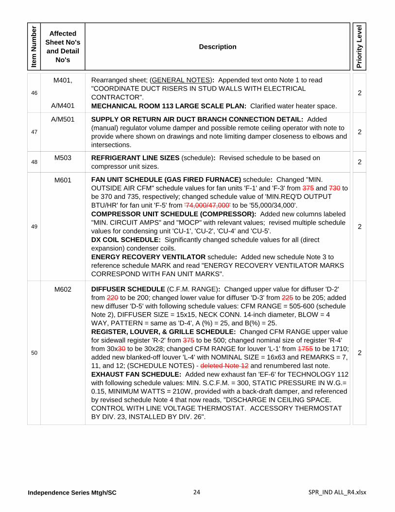
Rearranged sheet; (GENERAL NOTES): Appended text onto Note 1 to read "COORDINATE DUCT RISERS IN STUD WALLS WITH ELECTRICAL CONTRACTOR".MECHANICAL ROOM 113 LARGE SCALE PLAN: Clarified water heater space.
2
47
A/M501 SUPPLY OR RETURN AIR DUCT BRANCH CONNECTION DETAIL: Added (manual) regulator volume damper and possible remote ceiling operator with note to provide where shown on drawings and note limiting damper closeness to elbows and intersections.
2
48M503 REFRIGERANT LINE SIZES (schedule): Revised schedule to be based on
compressor unit sizes. 2
49
M601 FAN UNIT SCHEDULE (GAS FIRED FURNACE) schedule: Changed "MIN. OUTSIDE AIR CFM" schedule values for fan units 'F-1' and 'F-3' from 375 and 730 to be 370 and 735, respectively; changed schedule value of 'MIN.REQ'D OUTPUT BTU/HR' for fan unit 'F-5' from '74,000/47,000' to be '55,000/34,000'.COMPRESSOR UNIT SCHEDULE (COMPRESSOR): Added new columns labeled "MIN. CIRCUIT AMPS" and "MOCP" with relevant values; revised multiple schedule values for condensing unit 'CU-1', 'CU-2', 'CU-4' and 'CU-5'.DX COIL SCHEDULE: Significantly changed schedule values for all (direct expansion) condenser coils.ENERGY RECOVERY VENTILATOR schedule: Added new schedule Note 3 to reference schedule MARK and read "ENERGY RECOVERY VENTILATOR MARKS CORRESPOND WITH FAN UNIT MARKS".
2
50
M602 DIFFUSER SCHEDULE (C.F.M. RANGE): Changed upper value for diffuser 'D-2' from 220 to be 200; changed lower value for diffuser 'D-3' from 225 to be 205; added new diffuser 'D-5' with following schedule values: CFM RANGE = 505-600 (schedule Note 2), DIFFUSER SIZE = 15x15, NECK CONN. 14-inch diameter, BLOW = 4 WAY, PATTERN = same as 'D-4', A (%) = 25, and B(%) = 25.REGISTER, LOUVER, & GRILLE SCHEDULE: Changed CFM RANGE upper value for sidewall register 'R-2' from 375 to be 500; changed nominal size of register 'R-4' from 30x30 to be 30x28; changed CFM RANGE for louver 'L-1' from 1755 to be 1710; added new blanked-off louver 'L-4' with NOMINAL SIZE = 16x63 and REMARKS = 7, 11, and 12; (SCHEDULE NOTES) - deleted Note 12 and renumbered last note.EXHAUST FAN SCHEDULE: Added new exhaust fan 'EF-6' for TECHNOLOGY 112 with following schedule values: MIN. S.C.F.M. = 300, STATIC PRESSURE IN W.G.= 0.15, MINIMUM WATTS = 210W, provided with a back-draft damper, and referenced by revised schedule Note 4 that now reads, "DISCHARGE IN CEILING SPACE. CONTROL WITH LINE VOLTAGE THERMOSTAT. ACCESSORY THERMOSTAT BY DIV. 23, INSTALLED BY DIV. 26".
2
Independence Series Mtgh/SC 25 SPR_IND ALL_R4.xlsx
Item
Num
ber
Affected Sheet No's and Detail
No's
Description
Prio
rity
Leve
l
51
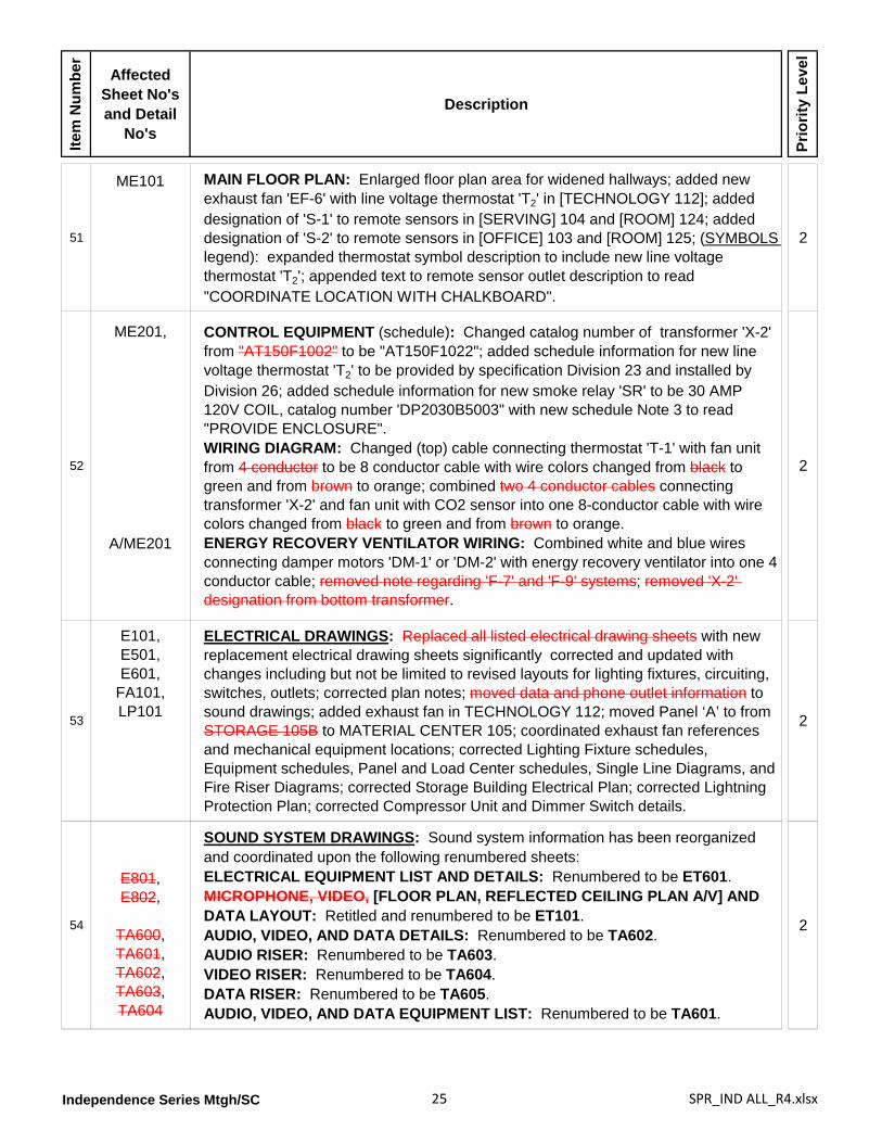
ME101 MAIN FLOOR PLAN: Enlarged floor plan area for widened hallways; added new exhaust fan 'EF-6' with line voltage thermostat 'T2' in [TECHNOLOGY 112]; added designation of 'S-1' to remote sensors in [SERVING] 104 and [ROOM] 124; added designation of 'S-2' to remote sensors in [OFFICE] 103 and [ROOM] 125; (SYMBOLS legend): expanded thermostat symbol description to include new line voltage thermostat 'T2'; appended text to remote sensor outlet description to read "COORDINATE LOCATION WITH CHALKBOARD".
2
52
ME201,
A/ME201
CONTROL EQUIPMENT (schedule): Changed catalog number of transformer 'X-2' from "AT150F1002" to be "AT150F1022"; added schedule information for new line voltage thermostat 'T2' to be provided by specification Division 23 and installed by Division 26; added schedule information for new smoke relay 'SR' to be 30 AMP 120V COIL, catalog number 'DP2030B5003" with new schedule Note 3 to read "PROVIDE ENCLOSURE".WIRING DIAGRAM: Changed (top) cable connecting thermostat 'T-1' with fan unit from 4 conductor to be 8 conductor cable with wire colors changed from black to green and from brown to orange; combined two 4 conductor cables connecting transformer 'X-2' and fan unit with CO2 sensor into one 8-conductor cable with wire colors changed from black to green and from brown to orange.ENERGY RECOVERY VENTILATOR WIRING: Combined white and blue wires connecting damper motors 'DM-1' or 'DM-2' with energy recovery ventilator into one 4 conductor cable; removed note regarding 'F-7' and 'F-9' systems; removed 'X-2' designation from bottom transformer.
2
53
E101,E501,E601,
FA101,LP101
ELECTRICAL DRAWINGS: Replaced all listed electrical drawing sheets with new replacement electrical drawing sheets significantly corrected and updated with changes including but not be limited to revised layouts for lighting fixtures, circuiting, switches, outlets; corrected plan notes; moved data and phone outlet information to sound drawings; added exhaust fan in TECHNOLOGY 112; moved Panel ‘A’ to from STORAGE 105B to MATERIAL CENTER 105; coordinated exhaust fan references and mechanical equipment locations; corrected Lighting Fixture schedules, Equipment schedules, Panel and Load Center schedules, Single Line Diagrams, and Fire Riser Diagrams; corrected Storage Building Electrical Plan; corrected Lightning Protection Plan; corrected Compressor Unit and Dimmer Switch details.
2
54
E801,E802,
TA600,TA601,TA602,TA603,TA604
SOUND SYSTEM DRAWINGS: Sound system information has been reorganized and coordinated upon the following renumbered sheets:ELECTRICAL EQUIPMENT LIST AND DETAILS: Renumbered to be ET601.MICROPHONE, VIDEO, [FLOOR PLAN, REFLECTED CEILING PLAN A/V] AND DATA LAYOUT: Retitled and renumbered to be ET101.AUDIO, VIDEO, AND DATA DETAILS: Renumbered to be TA602.AUDIO RISER: Renumbered to be TA603.VIDEO RISER: Renumbered to be TA604.DATA RISER: Renumbered to be TA605.AUDIO, VIDEO, AND DATA EQUIPMENT LIST: Renumbered to be TA601.
2
Independence Series Mtgh/SC 26 SPR_IND ALL_R4.xlsx
Item
Num
ber
Affected Sheet No's and Detail
No's
Description
Prio
rity
Leve
l
Independence 170 Meetinghouse [IPD-MH-10-04]
1
G101
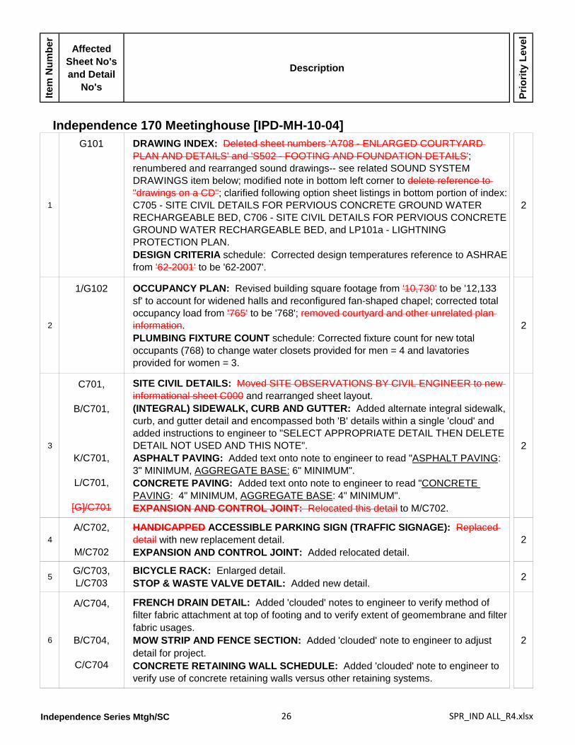
DRAWING INDEX: Deleted sheet numbers 'A708 - ENLARGED COURTYARD PLAN AND DETAILS' and 'S502 - FOOTING AND FOUNDATION DETAILS'; renumbered and rearranged sound drawings-- see related SOUND SYSTEM DRAWINGS item below; modified note in bottom left corner to delete reference to "drawings on a CD"; clarified following option sheet listings in bottom portion of index: C705 - SITE CIVIL DETAILS FOR PERVIOUS CONCRETE GROUND WATER RECHARGEABLE BED, C706 - SITE CIVIL DETAILS FOR PERVIOUS CONCRETE GROUND WATER RECHARGEABLE BED, and LP101a - LIGHTNING PROTECTION PLAN.DESIGN CRITERIA schedule: Corrected design temperatures reference to ASHRAE from '62-2001' to be '62-2007'.
2
2
1/G102 OCCUPANCY PLAN: Revised building square footage from '10,730' to be '12,133 sf' to account for widened halls and reconfigured fan-shaped chapel; corrected total occupancy load from '765' to be '768'; removed courtyard and other unrelated plan information.PLUMBING FIXTURE COUNT schedule: Corrected fixture count for new total occupants (768) to change water closets provided for men = 4 and lavatories provided for women = 3.
2
3
C701,
B/C701,
K/C701,
L/C701,
[G]/C701
SITE CIVIL DETAILS: Moved SITE OBSERVATIONS BY CIVIL ENGINEER to new informational sheet C000 and rearranged sheet layout.(INTEGRAL) SIDEWALK, CURB AND GUTTER: Added alternate integral sidewalk, curb, and gutter detail and encompassed both 'B' details within a single 'cloud' and added instructions to engineer to "SELECT APPROPRIATE DETAIL THEN DELETE DETAIL NOT USED AND THIS NOTE".ASPHALT PAVING: Added text onto note to engineer to read "ASPHALT PAVING: 3" MINIMUM, AGGREGATE BASE: 6" MINIMUM".CONCRETE PAVING: Added text onto note to engineer to read "CONCRETE PAVING: 4" MINIMUM, AGGREGATE BASE: 4" MINIMUM".EXPANSION AND CONTROL JOINT: Relocated this detail to M/C702.
2
4A/C702,
M/C702
HANDICAPPED ACCESSIBLE PARKING SIGN (TRAFFIC SIGNAGE): Replaced detail with new replacement detail.EXPANSION AND CONTROL JOINT: Added relocated detail.
2
5G/C703,L/C703
BICYCLE RACK: Enlarged detail.STOP & WASTE VALVE DETAIL: Added new detail. 2
6
A/C704,
B/C704,
C/C704
FRENCH DRAIN DETAIL: Added 'clouded' notes to engineer to verify method of filter fabric attachment at top of footing and to verify extent of geomembrane and filter fabric usages.MOW STRIP AND FENCE SECTION: Added 'clouded' note to engineer to adjust detail for project.CONCRETE RETAINING WALL SCHEDULE: Added 'clouded' note to engineer to verify use of concrete retaining walls versus other retaining systems.
2
Independence Series Mtgh/SC 27 SPR_IND ALL_R4.xlsx
Item
Num
ber
Affected Sheet No's and Detail
No's
Description
Prio
rity
Leve
l
7C801 STORAGE BUILDING: Replaced this sheet entirely with a new sheet detailing a
three-room storage building. 2
8
1/A101 FLOOR PLAN: Reconfigured CHAPEL 133 into a fan-shaped space to also modify MECHANICAL 132 and MECHANICAL 137; added 15 inches between Gridlines 'C' and 'D' to widen HALL 106; added 12 inches between Gridlines '5' and '6' to widen HALL 106; added 12 inches between Gridlines '4' and '5' to widen FOYER 131; regenerated all dimensions for uniformity in appearance and improve legibility; changed exterior wall dimensions to also measure to centerline of stud; deleted Door 130B and changed Door 130A to be 130; clarified front exit door in FOYER 131 to be Door 131A and rear exit door to be Door 131B; relocated electrical panel from STORAGE 105B to MATERIAL CENTER 105; corrected sheet reference for metal threshold between CHAPEL 133 and CULTURAL CENTER 140 from 'A802' to be 'A803'; corrected sheet reference for coat rack in HALL 121 from 'A803' to be 'A802'; corrected elevation reference in courtyard looking at exterior wall along Gridline '5' from '8/A203' to be '7/A203'; deleted all courtyard information and elevation reference between Gridlines '4' and '5' looking at exterior wall along Gridline 'D'; changed building section between Gridlines '4' and '5' from 'C/A303' to be 'D/A303'; added visual display cabinet 'V9' in HALL 106 on wall centered between Doors 105A and 105B.GENERAL NOTES: Rearranged and corrected Notes 1, 6, 10, 12 through 18.
2
9
1/A102 WALL TYPES MAIN FLOOR PLAN: Revised floor plan for widened hallways and reconfigured chapel/mechanical spaces; removed courtyard and other unrelated plan information; changed wall types between CLERK 102 and OFFICE 103 and between OFFICE 125 and CLERK 126 from 'W4-4' to be 'W4-4A'; changed exterior wall type at CLERK 102, OFFICE 103, OFFICE 125, and CLERK 126 from 'W6-3' to be 'W6-2'; changed wall type between ROOM 104 and MATERIAL CENTER 105 from 'W4-1' to be 'W6-1'; changed wall type between FONT 110 and ROOM 111 from 'W6-4A' to be 'W6-4'; changed wall type between CHAPEL 133 and each of MECHANICAL 132 and MECHANICAL 137 from 'W10-1' to be 'W6-5' (reconfigured chapel).
2
10A103 WALL TYPES: Wall Type 'W6-3' - deleted redundant note about gypsum board;
Wall Types 'W6-2', 'W6-7', and 'W8-1' - deleted vapor barrier from inside face of exterior wall studs; deleted all 'revision clouds'.
2
11
1/A104 ROOF PLAN: Revised roof in accordance with increased floor plan areas; added building section cut references; added 20-inch square attic ventilation opening cut through lower roof sheathing at overbuild area between Gridlines 'C' and 'D' and along Gridline '5'; clarified downspouts and continuous gutters; removed note for future folding partition header.
2
12D/A105,E/A105
(RIDGE VENTs): Replaced contractor-fabricated ridge vent with prefabricated metal ridge vent. 2
13
1/A106 EQUIPMENT PLATFORM PLAN: Modified chapel and mechanical spaces to fan-shaped configuration; increased floor plan areas to reflect widened hallways; corrected sheet references for ships ladder and access ladder from 'A802' to be 'A803'; removed unrelated plan information.
2
Independence Series Mtgh/SC 28 SPR_IND ALL_R4.xlsx
Item
Num
ber
Affected Sheet No's and Detail
No's
Description
Prio
rity
Leve
l
14
A151,
1/A151
GENERAL NOTES: Revised Note 4 text.CEILING FINISH SCHEDULE: Changed gypsum board in Ceiling Type 'C9' to be "NOT PAINTED".LEGEND (Symbols): Added detail reference for ACCESS PANEL to read "SEE G/A801".REFLECTED CEILING PLAN: Removed unrelated plan information and provided missing plan information; revised floor plan for widened hallways and reconfigured chapel/mechanical spaces; changed dimensions for positioning raised ceiling areas in [MULTI-USE 119] and [FOYER 131]; changed ceiling for [FOYER 101] from Type 'C2' to be 'C1'; changed ceilings for [ELECTRICAL 114 and RISER 115] from Type 'C4' to be 'C9'; changed ceilings in [MULTI-USE 119 raised ceiling area], [FOYER 131 raised ceiling area], [CHAPEL 133], [VESTIBULE 138], and [CULTURAL CENTER 140] from Type 'C5' to be 'C4'; changed ceilings in [MECHANICAL 132] and [MECHANICAL 137] from Type 'C4' to be 'C5'; deleted ceiling Type 'C4 from [FOYER 101].
2
15
1/A201,
2/A201
ELEVATION: Widened elevations to match floor plan for new hallway widths and reconfigured chapel/mechanical spaces; changed sheet reference for building signage from 'A803' to be 'A802'; changed building section reference between Gridlines '4' and '5' from 'C/A303' to be 'D/A303'; removed 'revision clouds'.ELEVATION: Lengthened elevations to match floor plan for new hallway widths; changed top of ridge elevation from '129'-6" ' to be '129'-8" '; deleted reference to spandrel glass in chapel and cultural center windows (near Gridline 'B'); removed 'revision clouds'.
2
16
3/A202,
4/A202
ELEVATION: Widened and lengthened elevations to match floor plan for widened hallways and reconfigured chapel/mechanical spaces; deleted courtyard information between Gridlines '4' and '5' including exit door from [SERVING AREA 130]; changed top of ridge elevation (near Gridline '2') from '129'-6" ' to be '129'-8" '; changed top of ridge elevation (near Gridline '6') from '117'-6" ' to be '117'-8" '; added note for "MASONRY EXPANSION JOINT, SEE C/A801" pointing to courtyard brickwork (between Gridlines '4' and '5'); added note for "HONED CMU" pointing to CMU banding between Gridlines '5' and '6'; added note for "EIFS INSERT, SEE G/A403" pointing to EIFS feature aligned below steeple; removed 'revision clouds'.ELEVATION: Changed top of ridge elevation (near Gridline 'E') from '129'-6" ' to be '129'-8" '; changed top of ridge elevation (near Gridline 'F') from '117'-6" ' to be '117'-8" '; removed 'revision clouds'.
2
17
5/A203,6/A203,7/A203,8/A203
(ELEVATIONs): Widened and lengthened elevations to match floor plan for widened hallways and reconfigured chapel/mechanical spaces; changed top of ridge elevation (ELEVATION 6, near Gridline 'D') from '129'-6" ' to be '129'-8" '; changed top of ridge elevation (ELEVATION 7, near Gridline 'E') from '117'-6" ' to be '117'-8" '; removed 'revision clouds'; (ELEVATION 5) - removed courtyard information.
2
18
A/A301 BUILDING SECTION: Widened building section to increase width of [HALL 106]; changed detail references for roof eaves at Gridlines '1' and '2' and at ceiling apex in CHAPEL 133; added detail references and note at lower roof over entry outside VESTIBULE 138 (near Gridline '1'); removed 'revision clouds'; revised section view at MECHANICAL 132 and VESTIBULE 138 areas (near Gridlines '1' and '4').
2
Independence Series Mtgh/SC 29 SPR_IND ALL_R4.xlsx
Item
Num
ber
Affected Sheet No's and Detail
No's
Description
Prio
rity
Leve
l
19
B/A302,
C/A302
BUILDING SECTION: Modified section to indicate angled wall for fan-shaped chapel and added section cut reference 'A/A502'; revised note pointing to roof ridge between Gridlines 'B' and 'C' to read "ROOFING MATERIAL OVER FRTW ROOF TRUSSES AND SHEATHING"; changed sheet reference in note pointing to organ chamber access ladder from 'A802' to be 'A803'; removed redundant note for gypsum board at ceiling of CHAPEL 133 between Gridlines 'B' and 'C'; removed 'revision clouds'; revised folding partition header between CHAPEL 133 and CULTURAL CENTER 140BUILDING SECTION: Widened building section to increase width of [HALL 106]; added pendant light fixtures in MULTI-USE 119; added detail reference 'J/A501' for springline of raised center ceiling area; changed cove reference from 'C/A501' to be H/A502'; added note pointing to raised ceiling area to read "5/8" GYPSUM BOARD"; added note pointing to underside of roof trusses to read "5/8" GYPSUM BOARD LID, TAPED ONLY"; added note pointing to flat side ceiling area to read "4" METAL STUD FRAMING AT 2'-0" O.C. TO SUPPORT 5/8" GYPSUM BOARD CEILING"; removed 'revision clouds'.
2
20
C[D]/A303
E/A303
BUILDING SECTION: Changed reference letter from 'C' to be 'D'; widened building section between Gridlines 'C' and 'D' for widened [HALL 121]; changed reference in carpet base note from 'N/A801' to be 'E/A801'; removed 'revision clouds' and courtyard information.BUILDING SECTION: Removed 'revision clouds'.
2
21F/A304 BUILDING SECTION: Lengthened building section to increase width of [HALL 121];
corrected width of door in MULTI-USE 119; corrected endwall at Gridline 'F' to show exterior exit door [106].
2
22E/A401,
G/A401
DETAIL: Removed roofing shingles from area beneath steeple and provided single-ply roof membrane over this covered area.SCUPPER DETAIL AT STEEPLE: Added new detail.
2
23
A/A402,
D/A402,G/A402,E/A402
DETAIL: Clarified baffle installation for proper ventilation between trusses; removed 'revision clouds' and 22-inch inside dimension.(DETAILs): Removed 'revision clouds'.
DETAIL: Removed vapor barrier from inside face of exterior stud.
2
24
A/A403,B/A403,C/A403,D/A403,E/A403
(EIFS DETAILS): Removed all (previous) revision notes and clouds.
2
25A404,
F/A404Removed all 'revision clouds'.DETAIL: Added note pointing to wall sheathing to read "WALL SHEATHING W/ AIR INFILTRATION BARRIER".
2
26E/A501,H/A501,J/A501
OVERBUILD SECTION: Removed 'revision clouds'.(COFFER DETAILs): Added new details. 2
Independence Series Mtgh/SC 30 SPR_IND ALL_R4.xlsx
Item
Num
ber
Affected Sheet No's and Detail
No's
Description
Prio
rity
Leve
l
27
A/A502,D/A502,G/A502,J/A502
SECTION: Removed sloped wall elements and associated notes.TRIM DETAIL: Removed 'revision cloud'.DETAIL: Corrected room numbers.LIGHT COVE AT WINDOW: Clarified louver installation over window; removed gypsum board closure panel from backside of window frame behind light cove; removed spandrel glass note.
2
28
A601 FINISH SCHEDULE: (FLOOR): Changed TECHNOLOGY 112 from 'F1' to be 'F4'; (BASE): Changed TECHNOLOGY 112 from 'B1' to be 'B3'; (WALLS): Added 'W5' to VESTIBULE 108A, WOMEN 109, and FONT 110, changed TECHNOLOGY 112 from 'W4' to be 'W5', changed ROOM 116, ROOM 117, ROOM 118, and MULTI-USE 119 from 'W4' to be 'W7', changed CUSTODIAL 122 from 'W4' to be 'W3 W5'; (CEILING): Changed FOYER 101 from 'C4' to be 'C1', , changed STORAGE 105B from 'C1' to be 'C2', changed MECHANICAL 107 and MECHANICAL 120 from 'C5' to be 'C6', added 'C4' to MULTI-USE 119, changed CUSTODIAL 122 from 'C1' to be 'C5', changed MECHANICAL 123 and MECHANICAL 137 from 'C2' to be 'C6', changed FOYER 131 from 'C5' to be 'C1', changed MECHANICAL 132 from 'C2' to be 'C5', changed CULTURAL CENTER 140 from 'C3' to be 'C4', changed STORAGE 141 from 'C5' to be 'C3'; (CEILING HEIGHT): Changed VESTIBULE 100, ELECTRIAL 114, and FIRE RISER 115 from 'CH1' to be 'CH4', changed MECHANICAL 113, MULTI-USE 119, CUSTODIAL 122, and TECHNOLOGY 136 from 'CH1' to be 'CH2', changed REST ROOM 128 and CUSTODIAN 129 from 'CH2' to be 'CH1'; (SPECIAL TRIM OR EQUIPMENT): Added 'S9' to MATERIAL CENTER 105, changed STORAGE 105B from 'S9' to be 'S15', deleted 'S9' from ELECTRICAL 114, added 'S1' to MULTI-USE 119, changed CUSTODIAL 122 from 'S2' to be 'S13'; added new room ROOM 125 with Floor 'F1', Base 'B1', Walls 'W4', Ceiling 'C1', and Ceiling Height 'CH1'; split ROOM 124 into two spaces (124A and 124B) with same names and finishes; corrected names of ROOM HALL 121, CLERK OFFICE 125, and HALL CLERK 126; added "(FLAT BLACK PAINT)" to ORGAN CHAMBER 201; (schedule DESCRIPTIONS): Base 'B2' - Base 'B2' - changed
2
reference from 'L/A801' to be 'M/A801', Base 'B6' - deleted reference 'J/A801', Wall 'W7' - replaced "NOT USED" with "WALL COVERING - "A" WAINSCOT WITH WALL COVERING "B" ABOVE", deleted Ceiling 'C7', Ceiling Height 'CH3' - changed height from '9'-2" ' to be '10'-0" ', deleted Ceiling Height 'CH7', added new Ceiling Height 'CH4' to be '9'-2" ', Special Equipment 'S6' - added "- SEE ELECTRICAL", Special Equipment 'S17' - replaced "NOT USED" with "DIMMER SWITCH - SEE ELECTRICAL", Special Equipment 'S21' - changed reference from 'A/A803' to be 'A/A802', added new Special Equipment 'S23' to read "16" DEEP FIXED SHELVING".
Independence Series Mtgh/SC 31 SPR_IND ALL_R4.xlsx
Item
Num
ber
Affected Sheet No's and Detail
No's
Description
Prio
rity
Leve
l
29
A602 DOOR SCHEDULE: Deleted Door 130B; changed Door 130A to be 130; (DOOR TYPE): Changed type of Door 130A from 'W' to be 'G'; changed type of Door 131B from 'W' to be 'A'; (DOOR SIZE): Standardized door sizes; changed width of Doors 110A and 110B to be 34 inches; changed width of Doors 119A and 301A from 36 inches to be 48 inches; changed width of both leaves of Door 123 from 36 inches to be 42 inches; (DOOR GLASS): Added glass 'G2' to Doors 130A and 133A; (FRAME PROFILE): Changed profile for Door 131B from 'A' to be 'B'; (FRAME DETAILS HEAD/JAMB): Changed detail sheet references for Doors 123, 124A, 124B, 125, 126, 127 from 'A503' to be 'A603'; (REMARKS): Doors 102, 107, 113, 123, and 132 - added threshold 'T3'; Door 104 - deleted threshold 'T3'; Doors 127 and 130A - deleted stop 'DS-1'; Door 128 - changed stop from 'DS-3' to be 'DS-1; Doors 129 and 140B - deleted stop 'DS-3'; Door 131B - changed threshold from 'T3' to be 'T1 and added stop 'DS-3'; Doors 140A and 140C - added threshold 'T1'; (STORAGE BUILDING): Added information for Doors 301, 302, 303, and 304; (FOLDING PARTITIONS): Added information for Folding Partitions P111A, P124, and P133.DOOR TYPES: Changed window in door Type 'G' to be 1'-4" high with bottom of window opening located 4'-8" above floor.(Door) FRAME PROFILES: Clarified overall width of Frame 'A' to be "WALL THICKNESS + 1-1/8" ".DOOR FRAME TYPES: Changed glazing in frames above height of door head from 'TEMPERED' to be (non-tempered) 'GLAZING'.WINDOW FRAME TYPES: Replaced 'SPANDREL GLASS (TYP.)' in Window Types 'C', 'D', and 'E' with glazing as noted; changed referenced room numbers from 139 140 and 141 142.WINDOW SCHEDULE: Changed window configuration from 'SINGLE HUNG' to be 'FIXED'.
2
30 A/A603 HEAD: Corrected brick installation above window; removed elevation reference. 2
31
A/A604,BA604,
E/A604
FOLDING PARTITION SECTION: Corrected truss bearing elevation.FOLDING PARTITION HEAD: Corrected and retitled detail; eliminated alternate head detail.FOLDING PARTITION POCKET JAMB: Revised folding partition end attachment from floating jamb to be fixed jamb; corrected and retitled detail.
2
32 A/A605 HEAD: Removed 'revision clouds'. 2
33A/A701,D/A701
ENLARGED FONT PLAN: Removed 'revision cloud'.BAPTISMAL FONT SECTION: Added dimensions for mirror. 2
34
1/A702,
H/A702,
J/A702,M/A702,N/A702,
P/A702,Q/A702
ENLARGED OFFICE/CLERK PLAN: Removed unrelated plan information; changed measure points and revised dimensions.SECTION: Changed detail reference to trim above wall cabinet from 'J/A704' to be 'P/A704'.CABINET ELEVATIONS ROOM 106: Removed 'revision cloud'.CABINET ELEVATIONS ROOM 106. Removed 'revision cloud'.SECTION: Changed detail reference to trim above wall cabinet from 'J/A704' to be 'P/A704'.ELEVATION: Removed 'revision cloud'.ELEVATION: Removed 'revision cloud'.
2
Independence Series Mtgh/SC 32 SPR_IND ALL_R4.xlsx
Item
Num
ber
Affected Sheet No's and Detail
No's
Description
Prio
rity
Leve
l
35
1/A703,
2/A703,
3/A703,
A/A703,B/A703,C/A703,D/A703,E/A703,H/A703,J/A703,K/A703,L/A703
ENLARGED RESTROOM AREA PLAN: Removed unrelated plan information; added dimensions, added missing room names, coordinated detail references, added stone thresholds at restroom entrance doors and door to MECHANICAL 107; eliminated slope lines to floor drain-- floor is to be level; .ENLARGED CUSTODIAL AREA PLAN: Eliminated slope lines to floor drain-- floor is to be level.ENLARGED RESTROOM FLOOR PLAN [128]: Reoriented plan view and added room number.(ELEVATIONs): Clarified accent wall tile pattern, corrected elevation view.
ELEVATION: Changed elevation view.(ELEVATIONs): Clarified accent wall tile pattern.
2
36C/A704,J/A704
ELEVATION: Corrected elevation view.SECTION: Lowered shelves. 2
371/A706,2/A706
ENLARGED ROSTRUM PLAN: Revised dimensions.ELEVATION - ORGAN CHAMBER: Reoriented horizontal section cut references to look downward; showed sides as cut sections.
2
38
A707,E/A707,F/A707,J/A707, K/A707,L/A707
ENLARGED ROSTRUM AND CHAPEL DETAILS: Rearranged sheet layout.ELEVATION: Removed 'revision clouds'.SECTION: Removed 'revision clouds'.RAILING DETAIL: Revised rostrum handrail.SECTION DETAIL: Changed title and replaced section with new detail.SECTION DETAIL: Changed title and replaced section with new detail.
2
39 A708 ENLARGED COURTYARD PLAN AND DETAILS: Deleted this sheet entirely. 2
40
A/A801,
D/A801,
J/A801,K/A801,
L/A801,M/A801,N/A801,P/A801
WOOD TRIM DETAIL: Replaced detail with new CERAMIC WALL TILE AT INSIDE CORNER.CEILING RIDGE DETAIL: Relocated detail to N/A801 and replaced with relocated VINYL THRESHOLD.THRESHOLD: Revised detail.STORAGE THRESHOLD DETAIL: Relocated detail to P/A801and replaced with relocated STONE THRESHOLD DETAIL.PAVER BASE DETAIL: Replaced detail with relocated THRESHOLD DETAIL.FLUSH COVE TILE BASE DETAIL: Added relocated detail.CEILING RIDGE DETAIL: Added relocated detail.STORAGE THRESHOLD DETAIL: Added relocated detail.
2
Independence Series Mtgh/SC 33 SPR_IND ALL_R4.xlsx
Item
Num
ber
Affected Sheet No's and Detail
No's
Description
Prio
rity
Leve
l
41
A/A802,
B/A802,
C/A802,
D/A802,
E/A802,
F/A802,
G/A802,
H/A802,
J/A802,
K/A802,L/A802
METAL THRESHOLD DETAIL: Relocated detail to A/A803 and replaced with relocated COAT RACK DETAIL.BASE DETAIL: Relocated detail to B/A803 and replaced with relocated FIRE EXTINGUISHER CABINET DETAILS.ACCESS LADDER DETAIL: Relocated detail to C/A803 and replaced with relocated SIGNAGE ELEVATION.BASKETBALL STANDARD DETAIL: Relocated detail to D/A803 and replaced with relocated SIGNAGE SECTION.VOLLEYBALL POST SLEEVE INSTALLATION DETAIL: Reassigned unused detail reference to relocated CHAIR RAIL AT WINDOW DETAIL.THRESHOLD DETAIL: Relocated detail to L/A801 and replaced with relocated STONE ADDRESS SIGNAGE ELEVATION.STONE THRESHOLD DETAIL: Relocated detail to K/A801 and replaced with relocated STONE ADDRESS SIGNAGE SECTION.SHIPS LADDER ELEVATIONS AT CHAPEL MECH. ROOMS: Relocated detail to F/A803 and replaced with relocated SECTION.FLUSH COVE TILE BASE DETAIL: Relocated detail to M/A801 and replaced with relocated SECTION; changed 8'-9" dimension to be 9'-3".GUARDRAIL: Relocated detail to G/A803.VINYL THRESHOLD: Relocated detail to D/A801.
2
42
A/A803,
B/A803,
C/A803,
D/A803,
E/A803,
F/A803,
G/A803
COAT RACK DETAIL: Relocated detail to A/A802 and replaced with relocated METAL THRESHOLD DETAIL.FIRE EXTINGUISHER CABINET DETAILS: Relocated detail to B/A802 and replaced with relocated BASE DETAIL.SIGNAGE ELEVATION: Relocated detail to C/A802 and replaced with relocated ACCESS LADDER DETAIL.SIGNAGE SECTION: Relocated detail to D/A802 and replaced with relocated BASKETBALL STANDARD DETAIL.CHAIR RAIL AT WINDOW DETAIL: Relocated detail to E/A802 and reassigned reference letter to "NOT USED".STONE ADDRESS SIGNAGE ELEVATION: Relocated detail to F/A802 and replaced with relocated SHIPS LADDER ELEVATIONS AT CHAPEL MECH. ROOMS.STONE ADDRESS SIGNAGE SECTION: Relocated detail to G/A802 and replaced with relocated TYP. GUARDRAIL.
2
Independence Series Mtgh/SC 34 SPR_IND ALL_R4.xlsx
Item
Num
ber
Affected Sheet No's and Detail
No's
Description
Prio
rity
Leve
l
43
1/F101 FURNISHINGS FLOOR PLAN: Revised floor plan for fan-shaped CHAPEL 133 and widened HALL 106 and HALL 121; removed unrelated plan information; deleted all courtyard information including exit door from SERVING AREA 130; added stone threshold at doors to VESTIBULE 108B and MECHANICAL 107; added sound thresholds at doors to CLERK 102, OFFICE 103, MECHANICAL 113, MECHANICAL 123, OFFICE 125, CLERK 126, and MECHANICAL 132.DRAPERY SCHEDULE: Added CLERK 102 ('1 SINGLE' drapery), ROOM 111 ('3 PAIR' draperies), and ROOM 124 ('2 PAIR' draperies); corrected room numbers for ROOM [MULTI-USE] 118 [119], OFFICE 123 [125], MOTHER'S ROOM 126 [127], CHAPEL 132, [133], ROSTRUM 133 [134], and CULTURAL CENTER 139 [140]; deleted draperies for exit door in MULTI-USE [118/119].PEW SCHEDULE: Revised schedule in response to chapel reconfiguration - changed PEW LENGTH of pew 'P6' from ' 5'-0" ' to be ' 3'-4" ' and added new pews 'P8' through 'P13' with respective schedule values and revised total lineal footage.
2
44A/F201,N/F201
PLAN VIEW: Clarified dimensions.HALF NEWEL POST: Clarified attachment of newel post to rostrum floor framing. 2
45
D/F202,
E/F202
SECTION: Repositioned microphone atop lectern and added note to read: "POSITION MICROPHONE TO SWING DOWN WITHIN 1" OF EDGE OF PULPIT".SECTION: Repositioned microphone atop lectern; changed reference for gang box locations from 'C/E804' to be 'B/ET602'.
2
46
1/F301 ROOM SIGNAGE LOCATION PLAN: Increased floor plan areas for widenend corridors and reconfigured fan-shaped chapel; deleted courtyard and other unrelated plan information; moved signage for OFFICE 103 and OFFICE 124 onto other side of angled wall corner; added room names; changed maximum occupancy for CHAPEL 133 from '252' to be '255'; deleted signage for (exterior access) door at MECHANICAL 137.
2
47F302 ROOM SIGNAGE SCHEDULES AND DETAILS: (BUILDING SIGNAGE
SCHEDULE) - changed maximum occupancy for sign reading '252' to be '255'; reduced number of MECHANICAL signs from '5' to be '4'.
2
48
S001 SCHEDULE ‘A’ (SOIL BEARING): Revised note to engineer regarding soils report to read, “ENGINEER OF RECORD TO INSERT FIRM NAME AND DATE OF SOILS REPORT AND VERIFY THE ALLOWABLE SOIL BEARING”SCHEDULE ‘B’: Added schedule Note 3 regarding material of fasteners and renumbered subsequent note.SCHEDULE ‘F’: (CONCRETE) Added note to engineer regarding needed adjustment to concrete strength values for different foundation systems that may be used; (WOOD) Added note instructing engineer to verify grades and species of wood to be used will match structural calculations; (WOOD, DIMENSION LUMBER, STRUCTURAL WALLS, 2x4): removed stud grade from allowed material; (WOOD, DIMENSION LUMBER, STRUCTURAL WALLS, 2x6): changed Hem Fir minimum grade from #2 to be #1; deleted schedule Notes 3 and 7 and renumbered subsequent notes.SCHEDULE ‘G’: Added new WIND COMPONENT AND CLADDING SCHEDULE.
2
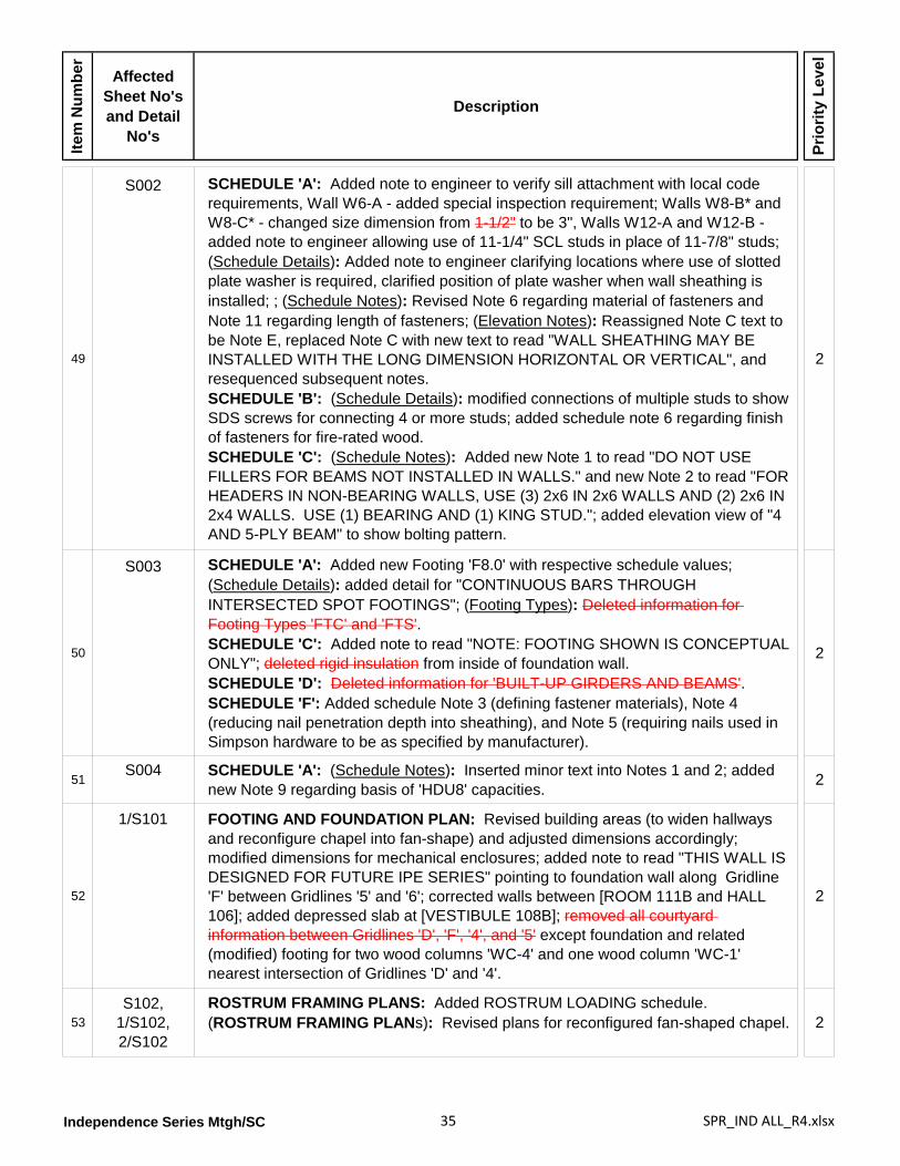
Independence Series Mtgh/SC 35 SPR_IND ALL_R4.xlsx
Item
Num
ber
Affected Sheet No's and Detail
No's
Description
Prio
rity
Leve
l
49
S002 SCHEDULE 'A': Added note to engineer to verify sill attachment with local code requirements, Wall W6-A - added special inspection requirement; Walls W8-B* and W8-C* - changed size dimension from 1-1/2" to be 3", Walls W12-A and W12-B - added note to engineer allowing use of 11-1/4" SCL studs in place of 11-7/8" studs; (Schedule Details): Added note to engineer clarifying locations where use of slotted plate washer is required, clarified position of plate washer when wall sheathing is installed; ; (Schedule Notes): Revised Note 6 regarding material of fasteners and Note 11 regarding length of fasteners; (Elevation Notes): Reassigned Note C text to be Note E, replaced Note C with new text to read "WALL SHEATHING MAY BE INSTALLED WITH THE LONG DIMENSION HORIZONTAL OR VERTICAL", and resequenced subsequent notes.SCHEDULE 'B': (Schedule Details): modified connections of multiple studs to show SDS screws for connecting 4 or more studs; added schedule note 6 regarding finish of fasteners for fire-rated wood.SCHEDULE 'C': (Schedule Notes): Added new Note 1 to read "DO NOT USE FILLERS FOR BEAMS NOT INSTALLED IN WALLS." and new Note 2 to read "FOR HEADERS IN NON-BEARING WALLS, USE (3) 2x6 IN 2x6 WALLS AND (2) 2x6 IN 2x4 WALLS. USE (1) BEARING AND (1) KING STUD."; added elevation view of "4 AND 5-PLY BEAM" to show bolting pattern.
2
50
S003 SCHEDULE 'A': Added new Footing 'F8.0' with respective schedule values; (Schedule Details): added detail for "CONTINUOUS BARS THROUGH INTERSECTED SPOT FOOTINGS"; (Footing Types): Deleted information for Footing Types 'FTC' and 'FTS'.SCHEDULE 'C': Added note to read "NOTE: FOOTING SHOWN IS CONCEPTUAL ONLY"; deleted rigid insulation from inside of foundation wall.SCHEDULE 'D': Deleted information for 'BUILT-UP GIRDERS AND BEAMS'.SCHEDULE 'F': Added schedule Note 3 (defining fastener materials), Note 4 (reducing nail penetration depth into sheathing), and Note 5 (requiring nails used in Simpson hardware to be as specified by manufacturer).
2
51S004 SCHEDULE 'A': (Schedule Notes): Inserted minor text into Notes 1 and 2; added
new Note 9 regarding basis of 'HDU8' capacities. 2
52
1/S101 FOOTING AND FOUNDATION PLAN: Revised building areas (to widen hallways and reconfigure chapel into fan-shape) and adjusted dimensions accordingly; modified dimensions for mechanical enclosures; added note to read "THIS WALL IS DESIGNED FOR FUTURE IPE SERIES" pointing to foundation wall along Gridline 'F' between Gridlines '5' and '6'; corrected walls between [ROOM 111B and HALL 106]; added depressed slab at [VESTIBULE 108B]; removed all courtyard information between Gridlines 'D', 'F', '4', and '5' except foundation and related (modified) footing for two wood columns 'WC-4' and one wood column 'WC-1' nearest intersection of Gridlines 'D' and '4'.
2
53S102,
1/S102,2/S102
ROSTRUM FRAMING PLANS: Added ROSTRUM LOADING schedule.(ROSTRUM FRAMING PLANs): Revised plans for reconfigured fan-shaped chapel. 2
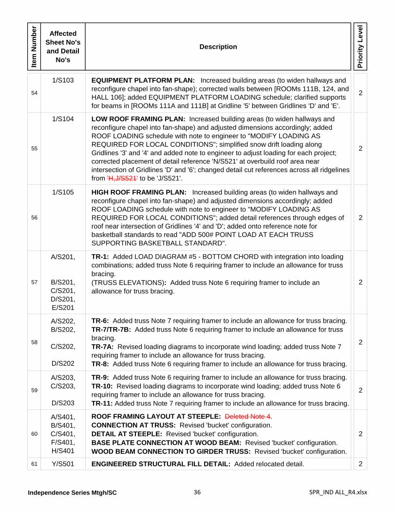
Independence Series Mtgh/SC 36 SPR_IND ALL_R4.xlsx
Item
Num
ber
Affected Sheet No's and Detail
No's
Description
Prio
rity
Leve
l
54
1/S103 EQUIPMENT PLATFORM PLAN: Increased building areas (to widen hallways and reconfigure chapel into fan-shape); corrected walls between [ROOMs 111B, 124, and HALL 106]; added EQUIPMENT PLATFORM LOADING schedule; clarified supports for beams in [ROOMs 111A and 111B] at Gridline '5' between Gridlines 'D' and 'E'.
2
55
1/S104 LOW ROOF FRAMING PLAN: Increased building areas (to widen hallways and reconfigure chapel into fan-shape) and adjusted dimensions accordingly; added ROOF LOADING schedule with note to engineer to "MODIFY LOADING AS REQUIRED FOR LOCAL CONDITIONS"; simplified snow drift loading along Gridlines '3' and '4' and added note to engineer to adjust loading for each project; corrected placement of detail reference 'N/S521' at overbuild roof area near intersection of Gridlines 'D' and '6'; changed detail cut references across all ridgelines from 'H,J/S521' to be 'J/S521'.
2
56
1/S105 HIGH ROOF FRAMING PLAN: Increased building areas (to widen hallways and reconfigure chapel into fan-shape) and adjusted dimensions accordingly; added ROOF LOADING schedule with note to engineer to "MODIFY LOADING AS REQUIRED FOR LOCAL CONDITIONS"; added detail references through edges of roof near intersection of Gridlines '4' and 'D'; added onto reference note for basketball standards to read "ADD 500# POINT LOAD AT EACH TRUSS SUPPORTING BASKETBALL STANDARD".
2
57
A/S201,
B/S201,C/S201,D/S201,E/S201
TR-1: Added LOAD DIAGRAM #5 - BOTTOM CHORD with integration into loading combinations; added truss Note 6 requiring framer to include an allowance for truss bracing.(TRUSS ELEVATIONS): Added truss Note 6 requiring framer to include an allowance for truss bracing.
2
58
A/S202,B/S202,
C/S202,
D/S202
TR-6: Added truss Note 7 requiring framer to include an allowance for truss bracing.TR-7/TR-7B: Added truss Note 6 requiring framer to include an allowance for truss bracing.TR-7A: Revised loading diagrams to incorporate wind loading; added truss Note 7 requiring framer to include an allowance for truss bracing.TR-8: Added truss Note 6 requiring framer to include an allowance for truss bracing.
2
59
A/S203,C/S203,
D/S203
TR-9: Added truss Note 6 requiring framer to include an allowance for truss bracing.TR-10: Revised loading diagrams to incorporate wind loading; added truss Note 6 requiring framer to include an allowance for truss bracing.TR-11: Added truss Note 7 requiring framer to include an allowance for truss bracing.
2
60
A/S401,B/S401,C/S401,F/S401,H/S401
ROOF FRAMING LAYOUT AT STEEPLE: Deleted Note 4. CONNECTION AT TRUSS: Revised 'bucket' configuration.DETAIL AT STEEPLE: Revised 'bucket' configuration.BASE PLATE CONNECTION AT WOOD BEAM: Revised 'bucket' configuration.WOOD BEAM CONNECTION TO GIRDER TRUSS: Revised 'bucket' configuration.
2
61 Y/S501 ENGINEERED STRUCTURAL FILL DETAIL: Added relocated detail. 2
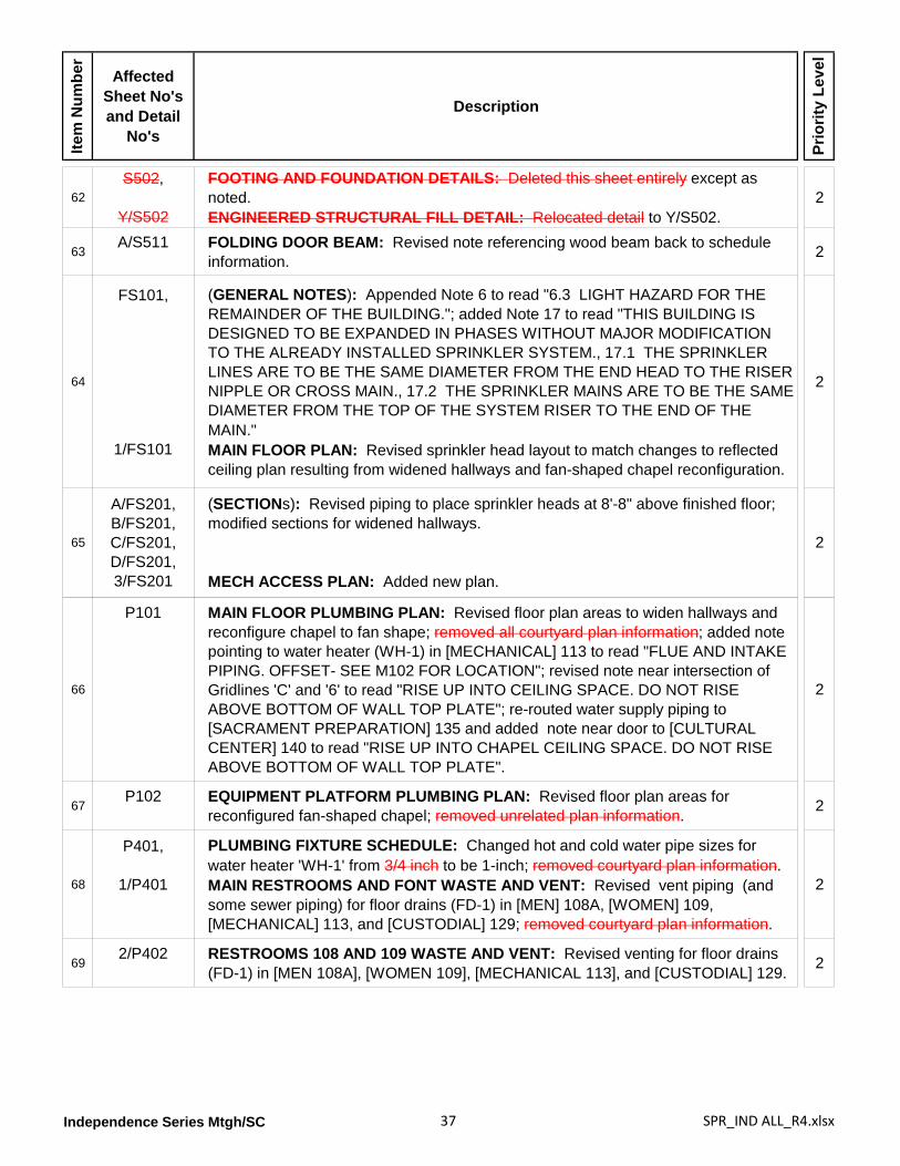
Independence Series Mtgh/SC 37 SPR_IND ALL_R4.xlsx
Item
Num
ber
Affected Sheet No's and Detail
No's
Description
Prio
rity
Leve
l
62S502,
Y/S502
FOOTING AND FOUNDATION DETAILS: Deleted this sheet entirely except as noted.ENGINEERED STRUCTURAL FILL DETAIL: Relocated detail to Y/S502.
2
63A/S511 FOLDING DOOR BEAM: Revised note referencing wood beam back to schedule
information. 2
64
FS101,
1/FS101
(GENERAL NOTES): Appended Note 6 to read "6.3 LIGHT HAZARD FOR THE REMAINDER OF THE BUILDING."; added Note 17 to read "THIS BUILDING IS DESIGNED TO BE EXPANDED IN PHASES WITHOUT MAJOR MODIFICATION TO THE ALREADY INSTALLED SPRINKLER SYSTEM., 17.1 THE SPRINKLER LINES ARE TO BE THE SAME DIAMETER FROM THE END HEAD TO THE RISER NIPPLE OR CROSS MAIN., 17.2 THE SPRINKLER MAINS ARE TO BE THE SAME DIAMETER FROM THE TOP OF THE SYSTEM RISER TO THE END OF THE MAIN."MAIN FLOOR PLAN: Revised sprinkler head layout to match changes to reflected ceiling plan resulting from widened hallways and fan-shaped chapel reconfiguration.
2
65
A/FS201,B/FS201,C/FS201,D/FS201,3/FS201
(SECTIONs): Revised piping to place sprinkler heads at 8'-8" above finished floor; modified sections for widened hallways.
MECH ACCESS PLAN: Added new plan.
2
66
P101 MAIN FLOOR PLUMBING PLAN: Revised floor plan areas to widen hallways and reconfigure chapel to fan shape; removed all courtyard plan information; added note pointing to water heater (WH-1) in [MECHANICAL] 113 to read "FLUE AND INTAKE PIPING. OFFSET- SEE M102 FOR LOCATION"; revised note near intersection of Gridlines 'C' and '6' to read "RISE UP INTO CEILING SPACE. DO NOT RISE ABOVE BOTTOM OF WALL TOP PLATE"; re-routed water supply piping to [SACRAMENT PREPARATION] 135 and added note near door to [CULTURAL CENTER] 140 to read "RISE UP INTO CHAPEL CEILING SPACE. DO NOT RISE ABOVE BOTTOM OF WALL TOP PLATE".
2
67P102 EQUIPMENT PLATFORM PLUMBING PLAN: Revised floor plan areas for
reconfigured fan-shaped chapel; removed unrelated plan information. 2
68
P401,
1/P401
PLUMBING FIXTURE SCHEDULE: Changed hot and cold water pipe sizes for water heater 'WH-1' from 3/4 inch to be 1-inch; removed courtyard plan information.MAIN RESTROOMS AND FONT WASTE AND VENT: Revised vent piping (and some sewer piping) for floor drains (FD-1) in [MEN] 108A, [WOMEN] 109, [MECHANICAL] 113, and [CUSTODIAL] 129; removed courtyard plan information.
2
692/P402 RESTROOMS 108 AND 109 WASTE AND VENT: Revised venting for floor drains
(FD-1) in [MEN 108A], [WOMEN 109], [MECHANICAL 113], and [CUSTODIAL] 129. 2
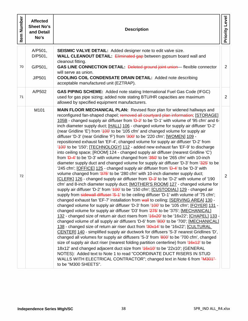
Independence Series Mtgh/SC 38 SPR_IND ALL_R4.xlsx
Item
Num
ber
Affected Sheet No's and Detail
No's
Description
Prio
rity
Leve
l
70
A/P501,D/P501,
G/P501,
J/P501
SEISMIC VALVE DETAIL: Added designer note to edit valve size.WALL CLEANOUT DETAIL: Eliminated gap between gypsum board wall and cleanout fitting.GAS LINE CONNECTION DETAIL: Deleted ground joint union— flexible connector will serve as union.COOLING COIL CONDENSATE DRAIN DETAIL: Added note describing acceptable manufactured unit (EZTRAP).
2
71A/P502 GAS PIPING SCHEME: Added note stating International Fuel Gas Code (IFGC)
used for gas pipe sizing; added note stating BTU/HR capacities are maximum allowed by specified equipment manufacturers.
2
72
M101 MAIN FLOOR MECHANICAL PLAN: Revised floor plan for widened hallways and reconfigured fan-shaped chapel; removed all courtyard plan information; [STORAGE] 105B - changed supply air diffuser from 'D-2' to be 'D-1' with volume of '95 cfm' and 6-inch diameter supply duct; [HALL] 106 - changed volume for supply air diffuser 'D-2' (near Gridline 'E') from '100' to be '105 cfm' and changed volume for supply air diffuser 'D-3' (near Gridline 'F') from '300' to be '220 cfm'; [WOMEN] 109 - repositioned exhaust fan 'EF-4', changed volume for supply air diffuser 'D-2' from '100' to be '150'; [TECHNOLOGY] 112 - added new exhaust fan 'EF-9' to discharge into ceiling space; [ROOM] 124 - changed supply air diffuser (nearest Gridline 'C') from 'D-4' to be 'D-3' with volume changed from '350' to be '265 cfm' with 10-inch diameter supply duct and changed volume for supply air diffuser 'D-3' from '325' to be '245 cfm'; [OFFICE] 125 - changed supply air diffuser from 'D-4' to be 'D-3' with volume changed from '375' to be '280 cfm' with 10-inch diameter supply duct; [CLERK] 126 - changed supply air diffuser from 'D-3' to be 'D-2' with volume of '190 cfm' and 8-inch diameter supply duct; [MOTHER'S ROOM] 127 - changed volume for supply air diffuser 'D-2' from '100' to be '150 cfm'; [CUSTODIAL] 129 - changed air supply from sidewall diffuser 'S-1' to be ceiling diffuser 'D-1' with volume of '75 cfm'; changed exhaust fan 'EF-7' installation from wall to ceiling; [SERVING AREA] 130 - changed volume for supply air diffuser 'D-3' from '100' to be '105 cfm'; [FOYER] 131 - changed volume for supply air diffuser 'D3' from '275' to be '375'; [MECHANICAL] 132 - changed size of return air duct risers from '16x20' to be '16x22'; [CHAPEL] 133 - changed volume of all supply air diffusers 'D-6' from '800' to be '700'; [MECHANICAL] 138 - changed size of return air riser duct from '30x14' to be '16x22'; [CULTURAL CENTER] 140 - simplified supply air ductwork for diffusers 'S-3' nearest Gridlines 'D', changed all volumes for supply air diffusers 'S-3' from '800' to be '700 cfm', changed size of supply air duct riser (nearest folding partition centerline) from '16x12' to be
2
18x12' and changed adjacent duct size from '16x10' to be '22x10'; (GENERAL NOTES): Added text to Note 1 to read "COORDINATE DUCT RISERS IN STUD WALLS WITH ELECTRICAL CONTRACTOR"; changed text in Note 6 from "M301" to be "M300 SHEETS".
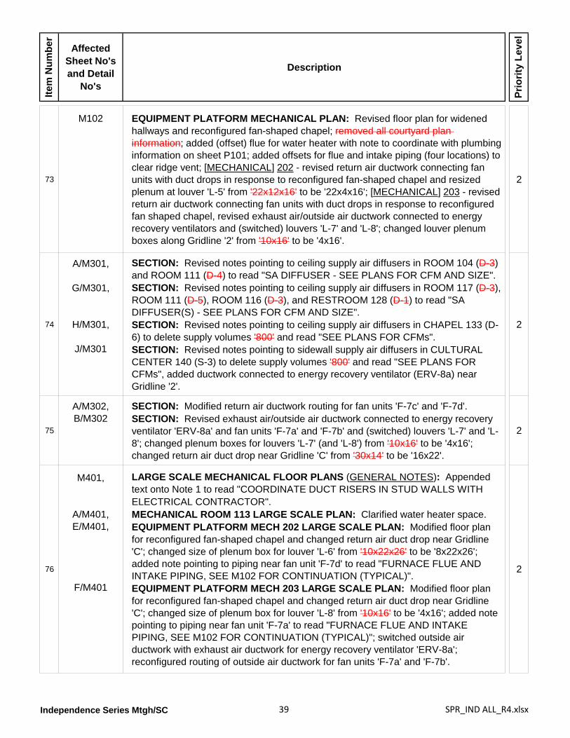
Independence Series Mtgh/SC 39 SPR_IND ALL_R4.xlsx
Item
Num
ber
Affected Sheet No's and Detail
No's
Description
Prio
rity
Leve
l
73
M102 EQUIPMENT PLATFORM MECHANICAL PLAN: Revised floor plan for widened hallways and reconfigured fan-shaped chapel; removed all courtyard plan information; added (offset) flue for water heater with note to coordinate with plumbing information on sheet P101; added offsets for flue and intake piping (four locations) to clear ridge vent; [MECHANICAL] 202 - revised return air ductwork connecting fan units with duct drops in response to reconfigured fan-shaped chapel and resized plenum at louver 'L-5' from '22x12x16' to be '22x4x16'; [MECHANICAL] 203 - revised return air ductwork connecting fan units with duct drops in response to reconfigured fan shaped chapel, revised exhaust air/outside air ductwork connected to energy recovery ventilators and (switched) louvers 'L-7' and 'L-8'; changed louver plenum boxes along Gridline '2' from '10x16' to be '4x16'.
2
74
A/M301,
G/M301,
H/M301,
J/M301
SECTION: Revised notes pointing to ceiling supply air diffusers in ROOM 104 (D-3) and ROOM 111 (D-4) to read "SA DIFFUSER - SEE PLANS FOR CFM AND SIZE".SECTION: Revised notes pointing to ceiling supply air diffusers in ROOM 117 (D-3), ROOM 111 (D-5), ROOM 116 (D-3), and RESTROOM 128 (D-1) to read "SA DIFFUSER(S) - SEE PLANS FOR CFM AND SIZE".SECTION: Revised notes pointing to ceiling supply air diffusers in CHAPEL 133 (D-6) to delete supply volumes '800' and read "SEE PLANS FOR CFMs".SECTION: Revised notes pointing to sidewall supply air diffusers in CULTURAL CENTER 140 (S-3) to delete supply volumes '800' and read "SEE PLANS FOR CFMs", added ductwork connected to energy recovery ventilator (ERV-8a) near Gridline '2'.
2
75
A/M302,B/M302
SECTION: Modified return air ductwork routing for fan units 'F-7c' and 'F-7d'.SECTION: Revised exhaust air/outside air ductwork connected to energy recovery ventilator 'ERV-8a' and fan units 'F-7a' and 'F-7b' and (switched) louvers 'L-7' and 'L-8'; changed plenum boxes for louvers 'L-7' (and 'L-8') from '10x16' to be '4x16'; changed return air duct drop near Gridline 'C' from '30x14' to be '16x22'.
2
76
M401,
A/M401,E/M401,
F/M401
LARGE SCALE MECHANICAL FLOOR PLANS (GENERAL NOTES): Appended text onto Note 1 to read "COORDINATE DUCT RISERS IN STUD WALLS WITH ELECTRICAL CONTRACTOR".MECHANICAL ROOM 113 LARGE SCALE PLAN: Clarified water heater space.EQUIPMENT PLATFORM MECH 202 LARGE SCALE PLAN: Modified floor plan for reconfigured fan-shaped chapel and changed return air duct drop near Gridline 'C'; changed size of plenum box for louver 'L-6' from '10x22x26' to be '8x22x26'; added note pointing to piping near fan unit 'F-7d' to read "FURNACE FLUE AND INTAKE PIPING, SEE M102 FOR CONTINUATION (TYPICAL)".EQUIPMENT PLATFORM MECH 203 LARGE SCALE PLAN: Modified floor plan for reconfigured fan-shaped chapel and changed return air duct drop near Gridline 'C'; changed size of plenum box for louver 'L-8' from '10x16' to be '4x16'; added note pointing to piping near fan unit 'F-7a' to read "FURNACE FLUE AND INTAKE PIPING, SEE M102 FOR CONTINUATION (TYPICAL)"; switched outside air ductwork with exhaust air ductwork for energy recovery ventilator 'ERV-8a'; reconfigured routing of outside air ductwork for fan units 'F-7a' and 'F-7b'.
2
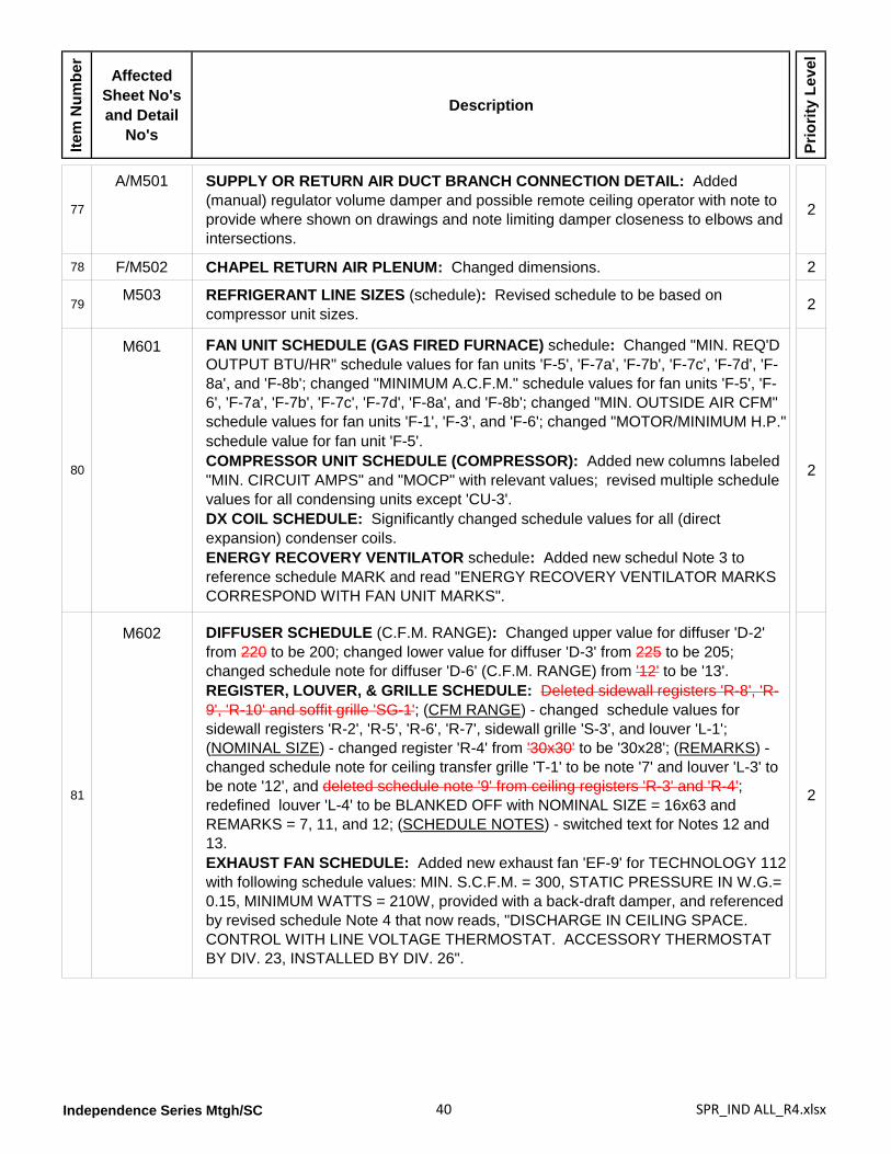
Independence Series Mtgh/SC 40 SPR_IND ALL_R4.xlsx
Item
Num
ber
Affected Sheet No's and Detail
No's
Description
Prio
rity
Leve
l
77
A/M501 SUPPLY OR RETURN AIR DUCT BRANCH CONNECTION DETAIL: Added (manual) regulator volume damper and possible remote ceiling operator with note to provide where shown on drawings and note limiting damper closeness to elbows and intersections.
2
78 F/M502 CHAPEL RETURN AIR PLENUM: Changed dimensions. 2
79M503 REFRIGERANT LINE SIZES (schedule): Revised schedule to be based on
compressor unit sizes. 2
80
M601 FAN UNIT SCHEDULE (GAS FIRED FURNACE) schedule: Changed "MIN. REQ'D OUTPUT BTU/HR" schedule values for fan units 'F-5', 'F-7a', 'F-7b', 'F-7c', 'F-7d', 'F-8a', and 'F-8b'; changed "MINIMUM A.C.F.M." schedule values for fan units 'F-5', 'F-6', 'F-7a', 'F-7b', 'F-7c', 'F-7d', 'F-8a', and 'F-8b'; changed "MIN. OUTSIDE AIR CFM" schedule values for fan units 'F-1', 'F-3', and 'F-6'; changed "MOTOR/MINIMUM H.P." schedule value for fan unit 'F-5'.COMPRESSOR UNIT SCHEDULE (COMPRESSOR): Added new columns labeled "MIN. CIRCUIT AMPS" and "MOCP" with relevant values; revised multiple schedule values for all condensing units except 'CU-3'.DX COIL SCHEDULE: Significantly changed schedule values for all (direct expansion) condenser coils.ENERGY RECOVERY VENTILATOR schedule: Added new schedul Note 3 to reference schedule MARK and read "ENERGY RECOVERY VENTILATOR MARKS CORRESPOND WITH FAN UNIT MARKS".
2
81
M602 DIFFUSER SCHEDULE (C.F.M. RANGE): Changed upper value for diffuser 'D-2' from 220 to be 200; changed lower value for diffuser 'D-3' from 225 to be 205; changed schedule note for diffuser 'D-6' (C.F.M. RANGE) from '12' to be '13'.REGISTER, LOUVER, & GRILLE SCHEDULE: Deleted sidewall registers 'R-8', 'R-9', 'R-10' and soffit grille 'SG-1'; (CFM RANGE) - changed schedule values for sidewall registers 'R-2', 'R-5', 'R-6', 'R-7', sidewall grille 'S-3', and louver 'L-1'; (NOMINAL SIZE) - changed register 'R-4' from '30x30' to be '30x28'; (REMARKS) - changed schedule note for ceiling transfer grille 'T-1' to be note '7' and louver 'L-3' to be note '12', and deleted schedule note '9' from ceiling registers 'R-3' and 'R-4'; redefined louver 'L-4' to be BLANKED OFF with NOMINAL SIZE = 16x63 and REMARKS = 7, 11, and 12; (SCHEDULE NOTES) - switched text for Notes 12 and 13.EXHAUST FAN SCHEDULE: Added new exhaust fan 'EF-9' for TECHNOLOGY 112 with following schedule values: MIN. S.C.F.M. = 300, STATIC PRESSURE IN W.G.= 0.15, MINIMUM WATTS = 210W, provided with a back-draft damper, and referenced by revised schedule Note 4 that now reads, "DISCHARGE IN CEILING SPACE. CONTROL WITH LINE VOLTAGE THERMOSTAT. ACCESSORY THERMOSTAT BY DIV. 23, INSTALLED BY DIV. 26".
2
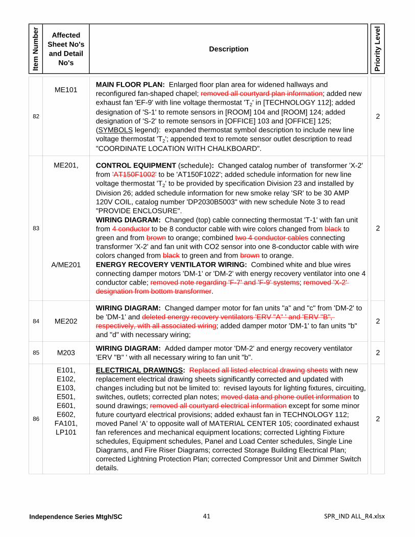
Independence Series Mtgh/SC 41 SPR_IND ALL_R4.xlsx
Item
Num
ber
Affected Sheet No's and Detail
No's
Description
Prio
rity
Leve
l
82
ME101MAIN FLOOR PLAN: Enlarged floor plan area for widened hallways and reconfigured fan-shaped chapel; removed all courtyard plan information; added new exhaust fan 'EF-9' with line voltage thermostat 'T2' in [TECHNOLOGY 112]; added designation of 'S-1' to remote sensors in [ROOM] 104 and [ROOM] 124; added designation of 'S-2' to remote sensors in [OFFICE] 103 and [OFFICE] 125; (SYMBOLS legend): expanded thermostat symbol description to include new line voltage thermostat 'T2'; appended text to remote sensor outlet description to read "COORDINATE LOCATION WITH CHALKBOARD".
2
83
ME201,
A/ME201
CONTROL EQUIPMENT (schedule): Changed catalog number of transformer 'X-2' from 'AT150F1002' to be 'AT150F1022'; added schedule information for new line voltage thermostat 'T2' to be provided by specification Division 23 and installed by Division 26; added schedule information for new smoke relay 'SR' to be 30 AMP 120V COIL, catalog number 'DP2030B5003" with new schedule Note 3 to read "PROVIDE ENCLOSURE".WIRING DIAGRAM: Changed (top) cable connecting thermostat 'T-1' with fan unit from 4 conductor to be 8 conductor cable with wire colors changed from black to green and from brown to orange; combined two 4 conductor cables connecting transformer 'X-2' and fan unit with CO2 sensor into one 8-conductor cable with wire colors changed from black to green and from brown to orange.ENERGY RECOVERY VENTILATOR WIRING: Combined white and blue wires connecting damper motors 'DM-1' or 'DM-2' with energy recovery ventilator into one 4 conductor cable; removed note regarding 'F-7' and 'F-9' systems; removed 'X-2' designation from bottom transformer.
2
84 ME202
WIRING DIAGRAM: Changed damper motor for fan units "a" and "c" from 'DM-2' to be 'DM-1' and deleted energy recovery ventilators 'ERV "A" ' and 'ERV "B", respectively, with all associated wiring; added damper motor 'DM-1' to fan units "b" and "d" with necessary wiring;
2
85 M203 WIRING DIAGRAM: Added damper motor 'DM-2' and energy recovery ventilator 'ERV "B" ' with all necessary wiring to fan unit "b". 2
86
E101,E102,E103,E501,E601,E602,
FA101,LP101
ELECTRICAL DRAWINGS: Replaced all listed electrical drawing sheets with new replacement electrical drawing sheets significantly corrected and updated with changes including but not be limited to: revised layouts for lighting fixtures, circuiting, switches, outlets; corrected plan notes; moved data and phone outlet information to sound drawings; removed all courtyard electrical information except for some minor future courtyard electrical provisions; added exhaust fan in TECHNOLOGY 112; moved Panel ‘A’ to opposite wall of MATERIAL CENTER 105; coordinated exhaust fan references and mechanical equipment locations; corrected Lighting Fixture schedules, Equipment schedules, Panel and Load Center schedules, Single Line Diagrams, and Fire Riser Diagrams; corrected Storage Building Electrical Plan; corrected Lightning Protection Plan; corrected Compressor Unit and Dimmer Switch details.
2
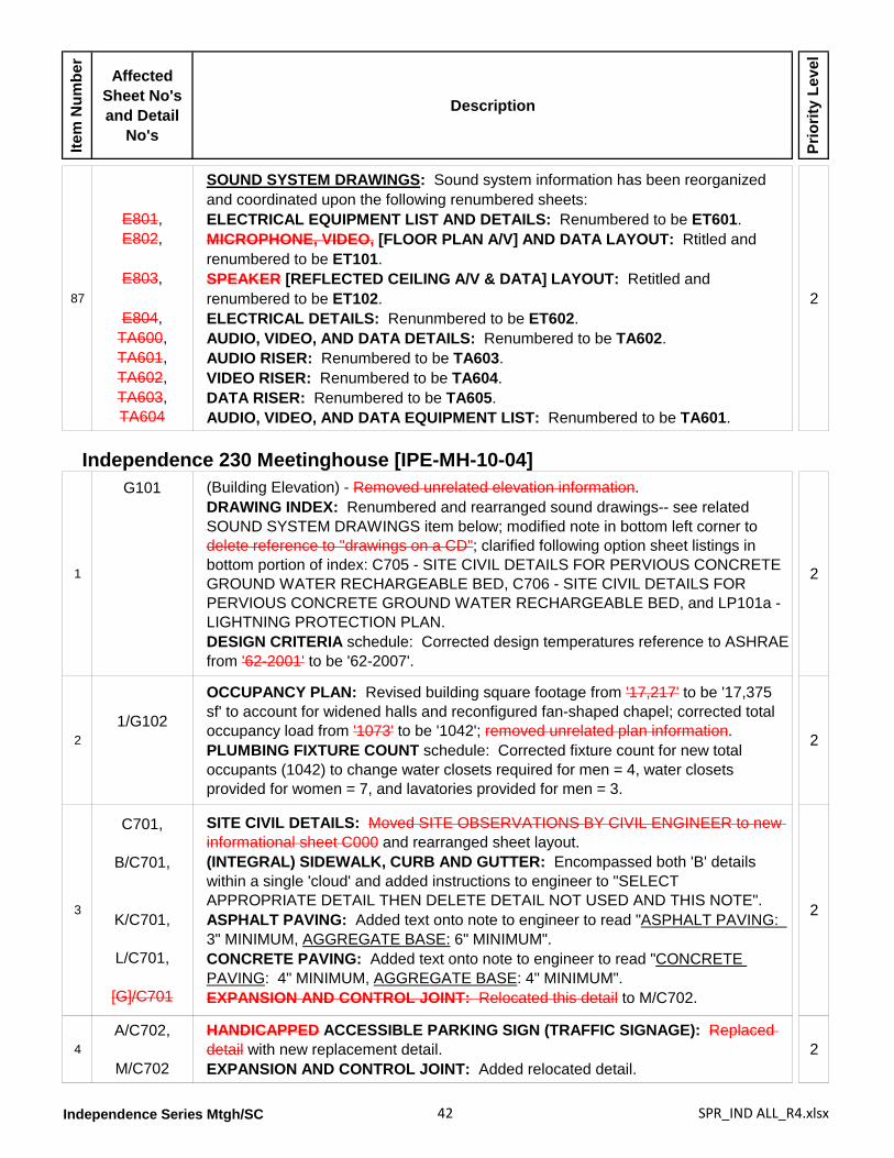
Independence Series Mtgh/SC 42 SPR_IND ALL_R4.xlsx
Item
Num
ber
Affected Sheet No's and Detail
No's
Description
Prio
rity
Leve
l
87
E801,E802,
E803,
E804,TA600,TA601,TA602,TA603,TA604
SOUND SYSTEM DRAWINGS: Sound system information has been reorganized and coordinated upon the following renumbered sheets:ELECTRICAL EQUIPMENT LIST AND DETAILS: Renumbered to be ET601.MICROPHONE, VIDEO, [FLOOR PLAN A/V] AND DATA LAYOUT: Rtitled and renumbered to be ET101.SPEAKER [REFLECTED CEILING A/V & DATA] LAYOUT: Retitled and renumbered to be ET102.ELECTRICAL DETAILS: Renunmbered to be ET602.AUDIO, VIDEO, AND DATA DETAILS: Renumbered to be TA602.AUDIO RISER: Renumbered to be TA603.VIDEO RISER: Renumbered to be TA604.DATA RISER: Renumbered to be TA605.AUDIO, VIDEO, AND DATA EQUIPMENT LIST: Renumbered to be TA601.
2
Independence 230 Meetinghouse [IPE-MH-10-04]
1
G101
(Building Elevation) - Removed unrelated elevation information.DRAWING INDEX: Renumbered and rearranged sound drawings-- see related SOUND SYSTEM DRAWINGS item below; modified note in bottom left corner to delete reference to "drawings on a CD"; clarified following option sheet listings in bottom portion of index: C705 - SITE CIVIL DETAILS FOR PERVIOUS CONCRETE GROUND WATER RECHARGEABLE BED, C706 - SITE CIVIL DETAILS FOR PERVIOUS CONCRETE GROUND WATER RECHARGEABLE BED, and LP101a - LIGHTNING PROTECTION PLAN.DESIGN CRITERIA schedule: Corrected design temperatures reference to ASHRAE from '62-2001' to be '62-2007'.
2
21/G102
OCCUPANCY PLAN: Revised building square footage from '17,217' to be '17,375 sf' to account for widened halls and reconfigured fan-shaped chapel; corrected total occupancy load from '1073' to be '1042'; removed unrelated plan information.PLUMBING FIXTURE COUNT schedule: Corrected fixture count for new total occupants (1042) to change water closets required for men = 4, water closets provided for women = 7, and lavatories provided for men = 3.
2
3
C701,
B/C701,
K/C701,
L/C701,
[G]/C701
SITE CIVIL DETAILS: Moved SITE OBSERVATIONS BY CIVIL ENGINEER to new informational sheet C000 and rearranged sheet layout.(INTEGRAL) SIDEWALK, CURB AND GUTTER: Encompassed both 'B' details within a single 'cloud' and added instructions to engineer to "SELECT APPROPRIATE DETAIL THEN DELETE DETAIL NOT USED AND THIS NOTE".ASPHALT PAVING: Added text onto note to engineer to read "ASPHALT PAVING: 3" MINIMUM, AGGREGATE BASE: 6" MINIMUM".CONCRETE PAVING: Added text onto note to engineer to read "CONCRETE PAVING: 4" MINIMUM, AGGREGATE BASE: 4" MINIMUM".EXPANSION AND CONTROL JOINT: Relocated this detail to M/C702.
2
4A/C702,
M/C702
HANDICAPPED ACCESSIBLE PARKING SIGN (TRAFFIC SIGNAGE): Replaced detail with new replacement detail.EXPANSION AND CONTROL JOINT: Added relocated detail.
2

Independence Series Mtgh/SC 43 SPR_IND ALL_R4.xlsx
Item
Num
ber
Affected Sheet No's and Detail
No's
Description
Prio
rity
Leve
l
5
A/C704,
B/C704,
C/C704
FRENCH DRAIN DETAIL: Added 'clouded' notes to engineer to verify method of filter fabric attachment at top of footing and to verify extent of geomembrane and filter fabric usages.MOW STRIP AND FENCE SECTION: Added 'clouded' note to engineer to adjust detail for project.CONCRETE RETAINING WALL SCHEDULE: Added 'clouded' note to engineer to verify use of concrete retaining walls versus other retaining systems.
2
6
1/C801,
C/C801,E/C801,
F/C801
FLOOR PLAN: Added hardware group for each door, as 'clouded' information to be used when storage building is a standalone project.HEAD: Removed soldier course brick from over door head.CROSS SECTION: Added soldier course brick with top at 2'-0" above top of foundation.ELEVATION: Clarified wall louver to be type 'L-5'.
2
7
1/A101 FLOOR PLAN: Reconfigured CHAPEL 133 into a fan-shaped space to also modify MECHANICAL 132 and MECHANICAL 137; added 12 inches to widen HALL 106, HALL 121, HALL 148, HALL 149, and HALL 159; regenerated all dimensions for uniformity in appearance and improve legibility; relocated electrical panel in MATERIAL CENTER 105; corrected sheet reference for metal threshold between CHAPEL 133 and CULTURAL CENTER 140 from 'A802' to be 'A803'; corrected sheet reference for coat rack in HALL 121 and HALL 148 from 'A803' to be 'A802'; corrected elevation references as follows - '2/A201' to be '3/A201', add new '2/A201' between Gridlines 1' and '2' and between Gridlines 'F' and 'G', '3/A202' to be '4/A202', '4/A202' to be '6/A202', '5/A203' to be '7/A203', '6/A203' to be '8/A203', '7/A203' to be '9/A203', '8/A203' to be '10/A203', '9/A203' to be '11/A203', and '10/A203' to be '12/A203'; changed building section reference between Gridlines 'E' and 'F' and from Gridlines '2' to '3' from 'C/A305' to be 'H/A305' with modified section cut routing; added visual display cabinet 'V9' in HALL 106 on wall centered between Doors 105A and 105B; assigned room number '173' to VOLLEYBALL STORAGE closet along Gridline '3' between Gridlines 'D' and 'E' with reference to enlarged floor plan at 'K/A803'.(GENERAL NOTES): Note 1 - changed exterior wall dimensions to also measure to centerline of stud; Note 4 - changed reference from 'H/A601' to be 'A/A601'; Note 6 - changed room numbers '108', '108A', '124A', '124B', '128', '154', and '157'; Note 10 - changed reference from 'B/A803' to be 'B/A802'; Note 12 - changed reference from 'A803' to be 'A802'; Note 15 - moved information to Note 6 and renumbered subsequent notes; Note [16] - changed reference from 'A/A707' to be 'A/A706'; Note [17] - changed reference from 'F/A802' to be 'F/A803'.
2
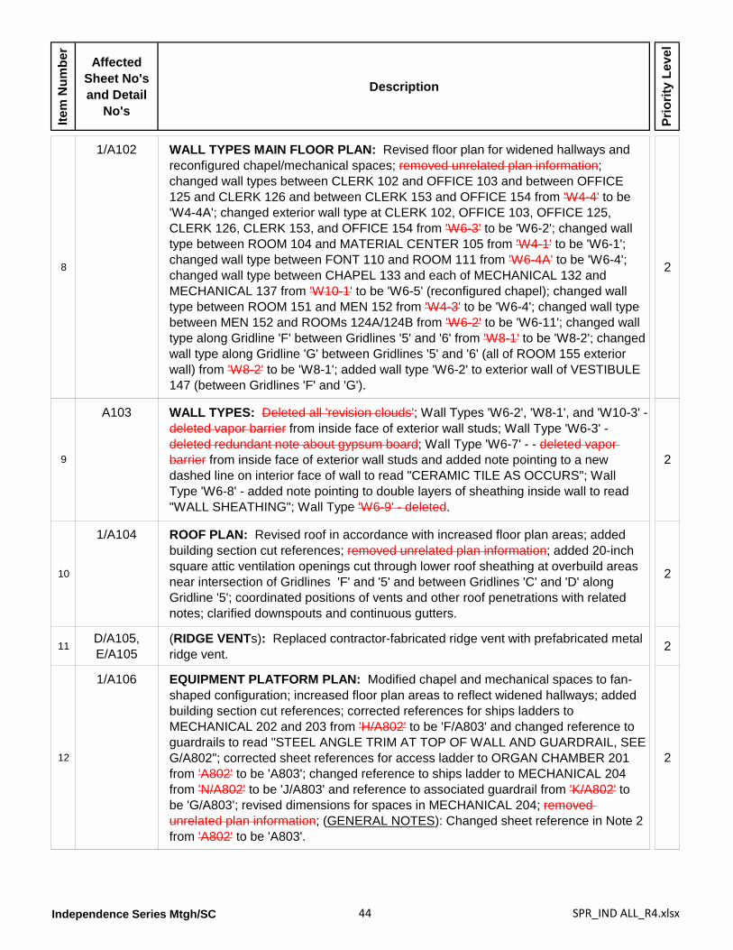
Independence Series Mtgh/SC 44 SPR_IND ALL_R4.xlsx
Item
Num
ber
Affected Sheet No's and Detail
No's
Description
Prio
rity
Leve
l
8
1/A102 WALL TYPES MAIN FLOOR PLAN: Revised floor plan for widened hallways and reconfigured chapel/mechanical spaces; removed unrelated plan information; changed wall types between CLERK 102 and OFFICE 103 and between OFFICE 125 and CLERK 126 and between CLERK 153 and OFFICE 154 from 'W4-4' to be 'W4-4A'; changed exterior wall type at CLERK 102, OFFICE 103, OFFICE 125, CLERK 126, CLERK 153, and OFFICE 154 from 'W6-3' to be 'W6-2'; changed wall type between ROOM 104 and MATERIAL CENTER 105 from 'W4-1' to be 'W6-1'; changed wall type between FONT 110 and ROOM 111 from 'W6-4A' to be 'W6-4'; changed wall type between CHAPEL 133 and each of MECHANICAL 132 and MECHANICAL 137 from 'W10-1' to be 'W6-5' (reconfigured chapel); changed wall type between ROOM 151 and MEN 152 from 'W4-3' to be 'W6-4'; changed wall type between MEN 152 and ROOMs 124A/124B from 'W6-2' to be 'W6-11'; changed wall type along Gridline 'F' between Gridlines '5' and '6' from 'W8-1' to be 'W8-2'; changed wall type along Gridline 'G' between Gridlines '5' and '6' (all of ROOM 155 exterior wall) from 'W8-2' to be 'W8-1'; added wall type 'W6-2' to exterior wall of VESTIBULE 147 (between Gridlines 'F' and 'G').
2
9
A103 WALL TYPES: Deleted all 'revision clouds'; Wall Types 'W6-2', 'W8-1', and 'W10-3' - deleted vapor barrier from inside face of exterior wall studs; Wall Type 'W6-3' - deleted redundant note about gypsum board; Wall Type 'W6-7' - - deleted vapor barrier from inside face of exterior wall studs and added note pointing to a new dashed line on interior face of wall to read "CERAMIC TILE AS OCCURS"; Wall Type 'W6-8' - added note pointing to double layers of sheathing inside wall to read "WALL SHEATHING"; Wall Type 'W6-9' - deleted.
2
10
1/A104 ROOF PLAN: Revised roof in accordance with increased floor plan areas; added building section cut references; removed unrelated plan information; added 20-inch square attic ventilation openings cut through lower roof sheathing at overbuild areas near intersection of Gridlines 'F' and '5' and between Gridlines 'C' and 'D' along Gridline '5'; coordinated positions of vents and other roof penetrations with related notes; clarified downspouts and continuous gutters.
2
11D/A105,E/A105
(RIDGE VENTs): Replaced contractor-fabricated ridge vent with prefabricated metal ridge vent. 2
12
1/A106 EQUIPMENT PLATFORM PLAN: Modified chapel and mechanical spaces to fan-shaped configuration; increased floor plan areas to reflect widened hallways; added building section cut references; corrected references for ships ladders to MECHANICAL 202 and 203 from 'H/A802' to be 'F/A803' and changed reference to guardrails to read "STEEL ANGLE TRIM AT TOP OF WALL AND GUARDRAIL, SEE G/A802"; corrected sheet references for access ladder to ORGAN CHAMBER 201 from 'A802' to be 'A803'; changed reference to ships ladder to MECHANICAL 204 from 'N/A802' to be 'J/A803' and reference to associated guardrail from 'K/A802' to be 'G/A803'; revised dimensions for spaces in MECHANICAL 204; removed unrelated plan information; (GENERAL NOTES): Changed sheet reference in Note 2 from 'A802' to be 'A803'.
2
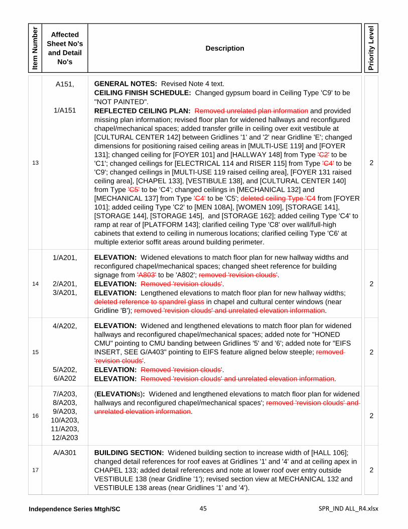
Independence Series Mtgh/SC 45 SPR_IND ALL_R4.xlsx
Item
Num
ber
Affected Sheet No's and Detail
No's
Description
Prio
rity
Leve
l
13
A151,
1/A151
GENERAL NOTES: Revised Note 4 text.CEILING FINISH SCHEDULE: Changed gypsum board in Ceiling Type 'C9' to be "NOT PAINTED".REFLECTED CEILING PLAN: Removed unrelated plan information and provided missing plan information; revised floor plan for widened hallways and reconfigured chapel/mechanical spaces; added transfer grille in ceiling over exit vestibule at [CULTURAL CENTER 142] between Gridlines '1' and '2' near Gridline 'E'; changed dimensions for positioning raised ceiling areas in [MULTI-USE 119] and [FOYER 131]; changed ceiling for [FOYER 101] and [HALLWAY 148] from Type 'C2' to be 'C1'; changed ceilings for [ELECTRICAL 114 and RISER 115] from Type 'C4' to be 'C9'; changed ceilings in [MULTI-USE 119 raised ceiling area], [FOYER 131 raised ceiling area], [CHAPEL 133], [VESTIBULE 138], and [CULTURAL CENTER 140] from Type 'C5' to be 'C4'; changed ceilings in [MECHANICAL 132] and [MECHANICAL 137] from Type 'C4' to be 'C5'; deleted ceiling Type 'C4 from [FOYER 101]; added ceiling Type 'C2' to [MEN 108A], [WOMEN 109], [STORAGE 141], [STORAGE 144], [STORAGE 145], and [STORAGE 162]; added ceiling Type 'C4' to ramp at rear of [PLATFORM 143]; clarified ceiling Type 'C8' over wall/full-high cabinets that extend to ceiling in numerous locations; clarified ceiling Type 'C6' at multiple exterior soffit areas around building perimeter.
2
14
1/A201,
2/A201,3/A201,
ELEVATION: Widened elevations to match floor plan for new hallway widths and reconfigured chapel/mechanical spaces; changed sheet reference for building signage from 'A803' to be 'A802'; removed 'revision clouds'.ELEVATION: Removed 'revision clouds'.ELEVATION: Lengthened elevations to match floor plan for new hallway widths; deleted reference to spandrel glass in chapel and cultural center windows (near Gridline 'B'); removed 'revision clouds' and unrelated elevation information.
2
15
4/A202,
5/A202,6/A202
ELEVATION: Widened and lengthened elevations to match floor plan for widened hallways and reconfigured chapel/mechanical spaces; added note for "HONED CMU" pointing to CMU banding between Gridlines '5' and '6'; added note for "EIFS INSERT, SEE G/A403" pointing to EIFS feature aligned below steeple; removed 'revision clouds'.ELEVATION: Removed 'revision clouds'.ELEVATION: Removed 'revision clouds' and unrelated elevation information.
2
16
7/A203,8/A203,9/A203,
10/A203,11/A203,12/A203
(ELEVATIONs): Widened and lengthened elevations to match floor plan for widened hallways and reconfigured chapel/mechanical spaces'; removed 'revision clouds' and unrelated elevation information. 2
17
A/A301 BUILDING SECTION: Widened building section to increase width of [HALL 106]; changed detail references for roof eaves at Gridlines '1' and '4' and at ceiling apex in CHAPEL 133; added detail references and note at lower roof over entry outside VESTIBULE 138 (near Gridline '1'); revised section view at MECHANICAL 132 and VESTIBULE 138 areas (near Gridlines '1' and '4').
2
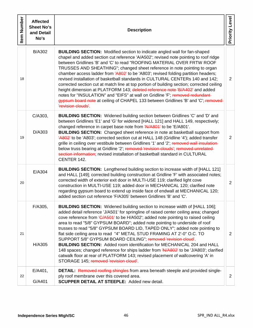
Independence Series Mtgh/SC 46 SPR_IND ALL_R4.xlsx
Item
Num
ber
Affected Sheet No's and Detail
No's
Description
Prio
rity
Leve
l
18
B/A302 BUILDING SECTION: Modified section to indicate angled wall for fan-shaped chapel and added section cut reference 'A/A502'; revised note pointing to roof ridge between Gridlines 'B' and 'C' to read "ROOFING MATERIAL OVER FRTW ROOF TRUSSES AND SHEATHING"; changed sheet reference in note pointing to organ chamber access ladder from 'A802' to be 'A803'; revised folding partition headers; revised installation of basketball standards in CULTURAL CENTERs 140 and 142; corrected section cut at match line at top portion of building section; corrected ceiling height dimension at PLATFORM 143; deleted reference note 'B/A402' and added notes for "INSULATION" and "EIFS" at wall on Gridline 'F'; removed redundant gypsum board note at ceiling of CHAPEL 133 between Gridlines 'B' and 'C'; removed 'revision clouds'.
2
19
C/A303,
D/A303
BUILDING SECTION: Widened building section between Gridlines 'C' and 'D' and between Gridlines 'E1' and 'G' for widened [HALL 121] and HALL 149, respectively; changed reference in carpet base note from 'N/A801' to be 'E/A801'.BUILDING SECTION: Changed sheet reference in note at basketball support from 'A802' to be 'A803'; corrected section cut at HALL 148 (Gridline '4'); added transfer grille in ceiling over vestibule between Gridlines '1' and '2'; removed wall insulation below truss bearing at Gridline '2'; removed 'revision clouds'; removed unrelated section information; revised installation of basketball standard in CULTURAL CENTER 142.
2
20
E/A304 BUILDING SECTION: Lengthened building section to increase width of [HALL 121] and HALL [149]; corrected building construction at Gridline 'F' with associated notes; corrected width of exterior exit door in MULTI-USE 119; clarified light cove construction in MULTI-USE 119; added door in MECHANICAL 120; clarified note regarding gypsum board to extend up inside face of endwall at MECHANICAL 120; added section cut reference 'F/A305' between Gridlines 'B' and 'C'.
2
21
F/A305,
H/A305
BUILDING SECTION: Widened building section to increase width of [HALL 106]; added detail reference 'J/A501' for springline of raised center ceiling area; changed cove reference from 'C/A501' to be H/A502'; added note pointing to raised ceiling area to read "5/8" GYPSUM BOARD"; added note pointing to underside of roof trusses to read "5/8" GYPSUM BOARD LID, TAPED ONLY"; added note pointing to flat side ceiling area to read "4" METAL STUD FRAMING AT 2'-0" O.C. TO SUPPORT 5/8" GYPSUM BOARD CEILING"; removed 'revision cloud'.BUILDING SECTION: Added room identification for MECHANICAL 204 and HALL 148 spaces; changed reference for ships ladder from 'N/A802' to be 'J/A803'; clarified catwalk floor at rear of PLATFORM 143; revised placement of wallcovering 'A' in STORAGE 145; removed 'revision cloud'.
2
22E/A401,
G/A401
DETAIL: Removed roofing shingles from area beneath steeple and provided single-ply roof membrane over this covered area.SCUPPER DETAIL AT STEEPLE: Added new detail.
2
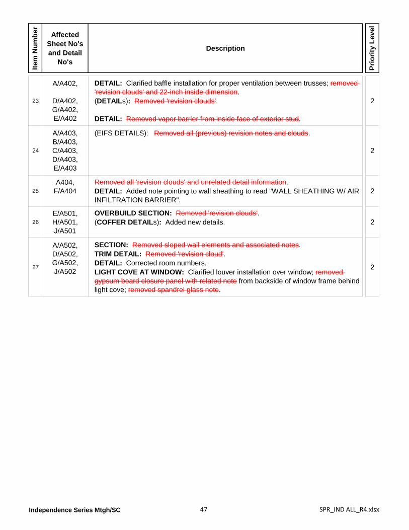
Independence Series Mtgh/SC 47 SPR_IND ALL_R4.xlsx
Item
Num
ber
Affected Sheet No's and Detail
No's
Description
Prio
rity
Leve
l
23
A/A402,
D/A402,G/A402,E/A402
DETAIL: Clarified baffle installation for proper ventilation between trusses; removed 'revision clouds' and 22-inch inside dimension.(DETAILs): Removed 'revision clouds'.
DETAIL: Removed vapor barrier from inside face of exterior stud.
2
24
A/A403,B/A403,C/A403,D/A403,E/A403
(EIFS DETAILS): Removed all (previous) revision notes and clouds.
2
25A404,
F/A404Removed all 'revision clouds' and unrelated detail information.DETAIL: Added note pointing to wall sheathing to read "WALL SHEATHING W/ AIR INFILTRATION BARRIER".
2
26E/A501,H/A501,J/A501
OVERBUILD SECTION: Removed 'revision clouds'.(COFFER DETAILs): Added new details. 2
27
A/A502,D/A502,G/A502,J/A502
SECTION: Removed sloped wall elements and associated notes.TRIM DETAIL: Removed 'revision cloud'.DETAIL: Corrected room numbers.LIGHT COVE AT WINDOW: Clarified louver installation over window; removed gypsum board closure panel with related note from backside of window frame behind light cove; removed spandrel glass note.
2
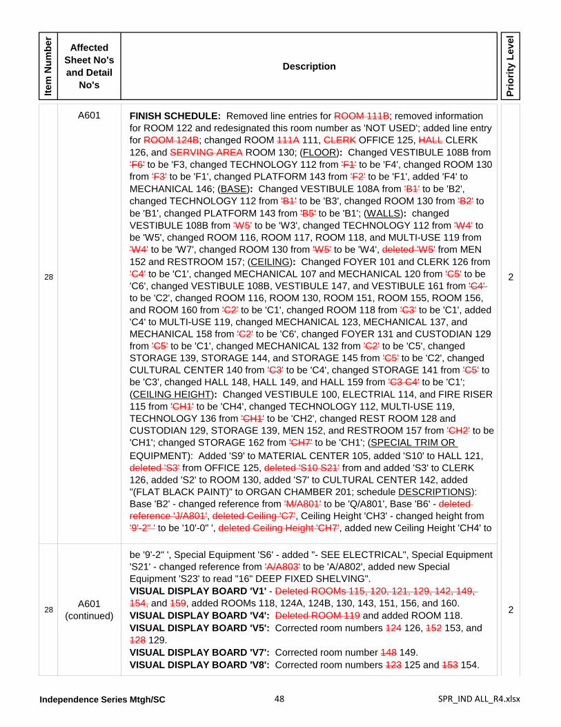
Independence Series Mtgh/SC 48 SPR_IND ALL_R4.xlsx
Item
Num
ber
Affected Sheet No's and Detail
No's
Description
Prio
rity
Leve
l
28
A601 FINISH SCHEDULE: Removed line entries for ROOM 111B; removed information for ROOM 122 and redesignated this room number as 'NOT USED'; added line entry for ROOM 124B; changed ROOM 111A 111, CLERK OFFICE 125, HALL CLERK 126, and SERVING AREA ROOM 130; (FLOOR): Changed VESTIBULE 108B from 'F6' to be 'F3, changed TECHNOLOGY 112 from 'F1' to be 'F4', changed ROOM 130 from 'F3' to be 'F1', changed PLATFORM 143 from 'F2' to be 'F1', added 'F4' to MECHANICAL 146; (BASE): Changed VESTIBULE 108A from 'B1' to be 'B2', changed TECHNOLOGY 112 from 'B1' to be 'B3', changed ROOM 130 from 'B2' to be 'B1', changed PLATFORM 143 from 'B5' to be 'B1'; (WALLS): changed VESTIBULE 108B from 'W5' to be 'W3', changed TECHNOLOGY 112 from 'W4' to be 'W5', changed ROOM 116, ROOM 117, ROOM 118, and MULTI-USE 119 from 'W4' to be 'W7', changed ROOM 130 from 'W5' to be 'W4', deleted 'W5' from MEN 152 and RESTROOM 157; (CEILING): Changed FOYER 101 and CLERK 126 from 'C4' to be 'C1', changed MECHANICAL 107 and MECHANICAL 120 from 'C5' to be 'C6', changed VESTIBULE 108B, VESTIBULE 147, and VESTIBULE 161 from 'C4' to be 'C2', changed ROOM 116, ROOM 130, ROOM 151, ROOM 155, ROOM 156, and ROOM 160 from 'C2' to be 'C1', changed ROOM 118 from 'C3' to be 'C1', added 'C4' to MULTI-USE 119, changed MECHANICAL 123, MECHANICAL 137, and MECHANICAL 158 from 'C2' to be 'C6', changed FOYER 131 and CUSTODIAN 129 from 'C5' to be 'C1', changed MECHANICAL 132 from 'C2' to be 'C5', changed STORAGE 139, STORAGE 144, and STORAGE 145 from 'C5' to be 'C2', changed CULTURAL CENTER 140 from 'C3' to be 'C4', changed STORAGE 141 from 'C5' to be 'C3', changed HALL 148, HALL 149, and HALL 159 from 'C3 C4' to be 'C1'; (CEILING HEIGHT): Changed VESTIBULE 100, ELECTRIAL 114, and FIRE RISER 115 from 'CH1' to be 'CH4', changed TECHNOLOGY 112, MULTI-USE 119, TECHNOLOGY 136 from 'CH1' to be 'CH2', changed REST ROOM 128 and CUSTODIAN 129, STORAGE 139, MEN 152, and RESTROOM 157 from 'CH2' to be 'CH1'; changed STORAGE 162 from 'CH7' to be 'CH1'; (SPECIAL TRIM OR
2
EQUIPMENT): Added 'S9' to MATERIAL CENTER 105, added 'S10' to HALL 121, deleted 'S3' from OFFICE 125, deleted 'S10 S21' from and added 'S3' to CLERK 126, added 'S2' to ROOM 130, added 'S7' to CULTURAL CENTER 142, added "(FLAT BLACK PAINT)" to ORGAN CHAMBER 201; schedule DESCRIPTIONS): Base 'B2' - changed reference from 'M/A801' to be 'Q/A801', Base 'B6' - deleted reference 'J/A801', deleted Ceiling 'C7', Ceiling Height 'CH3' - changed height from '9'-2" ' to be '10'-0" ', deleted Ceiling Height 'CH7', added new Ceiling Height 'CH4' to
28A601
(continued)
be '9'-2" ', Special Equipment 'S6' - added "- SEE ELECTRICAL", Special Equipment 'S21' - changed reference from 'A/A803' to be 'A/A802', added new Special Equipment 'S23' to read "16" DEEP FIXED SHELVING".VISUAL DISPLAY BOARD 'V1' - Deleted ROOMs 115, 120, 121, 129, 142, 149, 154, and 159, added ROOMs 118, 124A, 124B, 130, 143, 151, 156, and 160.VISUAL DISPLAY BOARD 'V4': Deleted ROOM 119 and added ROOM 118.VISUAL DISPLAY BOARD 'V5': Corrected room numbers 124 126, 152 153, and 128 129.VISUAL DISPLAY BOARD 'V7': Corrected room number 148 149.VISUAL DISPLAY BOARD 'V8': Corrected room numbers 123 125 and 153 154.
2
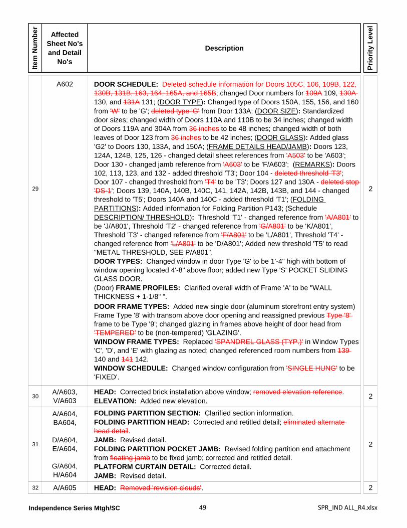
Independence Series Mtgh/SC 49 SPR_IND ALL_R4.xlsx
Item
Num
ber
Affected Sheet No's and Detail
No's
Description
Prio
rity
Leve
l
29
A602 DOOR SCHEDULE: Deleted schedule information for Doors 105C, 106, 109B, 122, 130B, 131B, 163, 164, 165A, and 165B; changed Door numbers for 109A 109, 130A 130, and 131A 131; (DOOR TYPE): Changed type of Doors 150A, 155, 156, and 160 from 'W' to be 'G'; deleted type 'G' from Door 133A; (DOOR SIZE): Standardized door sizes; changed width of Doors 110A and 110B to be 34 inches; changed width of Doors 119A and 304A from 36 inches to be 48 inches; changed width of both leaves of Door 123 from 36 inches to be 42 inches; (DOOR GLASS): Added glass 'G2' to Doors 130, 133A, and 150A; (FRAME DETAILS HEAD/JAMB): Doors 123, 124A, 124B, 125, 126 - changed detail sheet references from 'A503' to be 'A603'; Door 130 - changed jamb reference from 'A603' to be 'F/A603'; (REMARKS): Doors 102, 113, 123, and 132 - added threshold 'T3'; Door 104 - deleted threshold 'T3'; Door 107 - changed threshold from 'T4' to be 'T3'; Doors 127 and 130A - deleted stop 'DS-1'; Doors 139, 140A, 140B, 140C, 141, 142A, 142B, 143B, and 144 - changed threshold to 'T5'; Doors 140A and 140C - added threshold 'T1'; (FOLDING PARTITIONS): Added information for Folding Partition P143; (Schedule DESCRIPTION/ THRESHOLD): Threshold 'T1' - changed reference from 'A/A801' to be 'J/A801', Threshold 'T2' - changed reference from 'G/A801' to be 'K/A801', Threshold 'T3' - changed reference from 'F/A801' to be 'L/A801', Threshold 'T4' - changed reference from 'L/A801' to be 'D/A801'; Added new threshold 'T5' to read "METAL THRESHOLD, SEE P/A801".DOOR TYPES: Changed window in door Type 'G' to be 1'-4" high with bottom of window opening located 4'-8" above floor; added new Type 'S' POCKET SLIDING GLASS DOOR.(Door) FRAME PROFILES: Clarified overall width of Frame 'A' to be "WALL THICKNESS + 1-1/8" ".
2
DOOR FRAME TYPES: Added new single door (aluminum storefront entry system) Frame Type '8' with transom above door opening and reassigned previous Type '8' frame to be Type '9'; changed glazing in frames above height of door head from 'TEMPERED' to be (non-tempered) 'GLAZING'.WINDOW FRAME TYPES: Replaced 'SPANDREL GLASS (TYP.)' in Window Types 'C', 'D', and 'E' with glazing as noted; changed referenced room numbers from 139 140 and 141 142. WINDOW SCHEDULE: Changed window configuration from 'SINGLE HUNG' to be 'FIXED'.
30A/A603,V/A603
HEAD: Corrected brick installation above window; removed elevation reference.ELEVATION: Added new elevation. 2
31
A/A604,BA604,
D/A604,E/A604,
G/A604,H/A604
FOLDING PARTITION SECTION: Clarified section information.FOLDING PARTITION HEAD: Corrected and retitled detail; eliminated alternate head detail.JAMB: Revised detail.FOLDING PARTITION POCKET JAMB: Revised folding partition end attachment from floating jamb to be fixed jamb; corrected and retitled detail.PLATFORM CURTAIN DETAIL: Corrected detail.JAMB: Revised detail.
2
32 A/A605 HEAD: Removed 'revision clouds'. 2
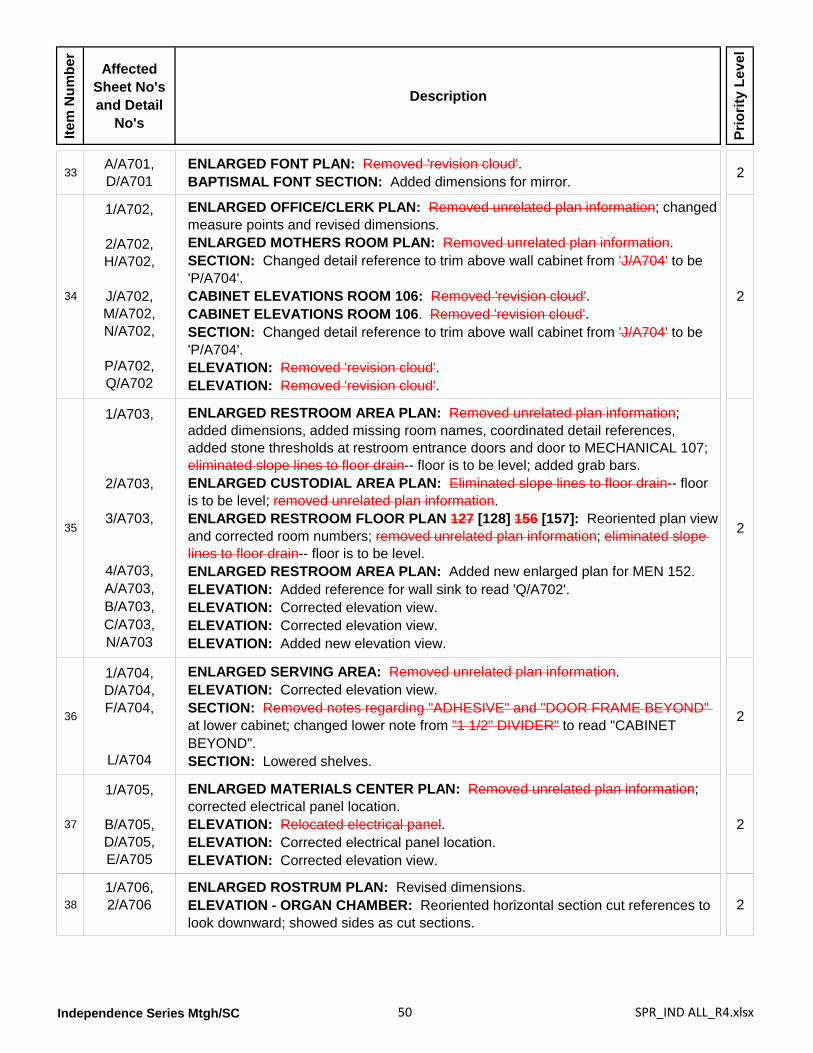
Independence Series Mtgh/SC 50 SPR_IND ALL_R4.xlsx
Item
Num
ber
Affected Sheet No's and Detail
No's
Description
Prio
rity
Leve
l
33A/A701,D/A701
ENLARGED FONT PLAN: Removed 'revision cloud'.BAPTISMAL FONT SECTION: Added dimensions for mirror. 2
34
1/A702,
2/A702,H/A702,
J/A702,M/A702,N/A702,
P/A702,Q/A702
ENLARGED OFFICE/CLERK PLAN: Removed unrelated plan information; changed measure points and revised dimensions.ENLARGED MOTHERS ROOM PLAN: Removed unrelated plan information.SECTION: Changed detail reference to trim above wall cabinet from 'J/A704' to be 'P/A704'.CABINET ELEVATIONS ROOM 106: Removed 'revision cloud'.CABINET ELEVATIONS ROOM 106. Removed 'revision cloud'.SECTION: Changed detail reference to trim above wall cabinet from 'J/A704' to be 'P/A704'.ELEVATION: Removed 'revision cloud'.ELEVATION: Removed 'revision cloud'.
2
35
1/A703,
2/A703,
3/A703,
4/A703,A/A703,B/A703,C/A703,N/A703
ENLARGED RESTROOM AREA PLAN: Removed unrelated plan information; added dimensions, added missing room names, coordinated detail references, added stone thresholds at restroom entrance doors and door to MECHANICAL 107; eliminated slope lines to floor drain-- floor is to be level; added grab bars.ENLARGED CUSTODIAL AREA PLAN: Eliminated slope lines to floor drain-- floor is to be level; removed unrelated plan information.ENLARGED RESTROOM FLOOR PLAN 127 [128] 156 [157]: Reoriented plan view and corrected room numbers; removed unrelated plan information; eliminated slope lines to floor drain-- floor is to be level.ENLARGED RESTROOM AREA PLAN: Added new enlarged plan for MEN 152.ELEVATION: Added reference for wall sink to read 'Q/A702'.ELEVATION: Corrected elevation view.ELEVATION: Corrected elevation view.ELEVATION: Added new elevation view.
2
36
1/A704,D/A704,F/A704,
L/A704
ENLARGED SERVING AREA: Removed unrelated plan information.ELEVATION: Corrected elevation view.SECTION: Removed notes regarding "ADHESIVE" and "DOOR FRAME BEYOND" at lower cabinet; changed lower note from "1 1/2" DIVIDER" to read "CABINET BEYOND".SECTION: Lowered shelves.
2
37
1/A705,
B/A705,D/A705,E/A705
ENLARGED MATERIALS CENTER PLAN: Removed unrelated plan information; corrected electrical panel location.ELEVATION: Relocated electrical panel.ELEVATION: Corrected electrical panel location.ELEVATION: Corrected elevation view.
2
381/A706,2/A706
ENLARGED ROSTRUM PLAN: Revised dimensions.ELEVATION - ORGAN CHAMBER: Reoriented horizontal section cut references to look downward; showed sides as cut sections.
2
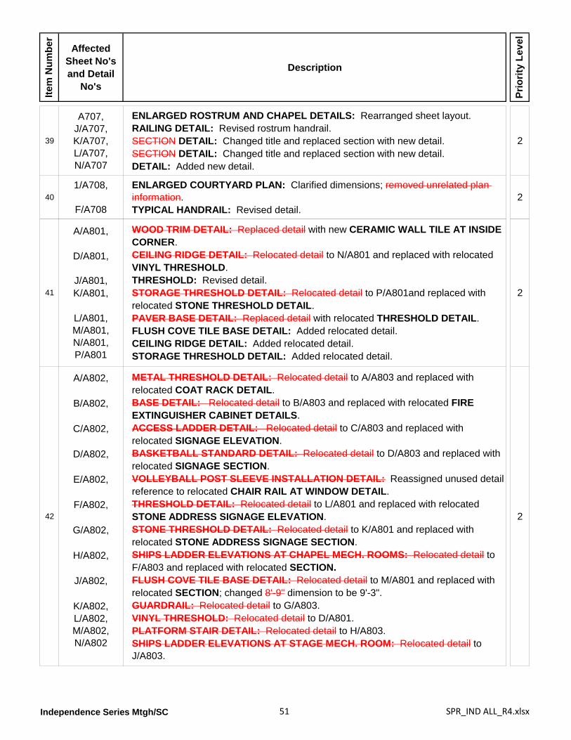
Independence Series Mtgh/SC 51 SPR_IND ALL_R4.xlsx
Item
Num
ber
Affected Sheet No's and Detail
No's
Description
Prio
rity
Leve
l
39
A707,J/A707, K/A707,L/A707,N/A707
ENLARGED ROSTRUM AND CHAPEL DETAILS: Rearranged sheet layout.RAILING DETAIL: Revised rostrum handrail.SECTION DETAIL: Changed title and replaced section with new detail.SECTION DETAIL: Changed title and replaced section with new detail.DETAIL: Added new detail.
2
401/A708,
F/A708
ENLARGED COURTYARD PLAN: Clarified dimensions; removed unrelated plan information.TYPICAL HANDRAIL: Revised detail.
2
41
A/A801,
D/A801,
J/A801,K/A801,
L/A801,M/A801,N/A801,P/A801
WOOD TRIM DETAIL: Replaced detail with new CERAMIC WALL TILE AT INSIDE CORNER.CEILING RIDGE DETAIL: Relocated detail to N/A801 and replaced with relocated VINYL THRESHOLD.THRESHOLD: Revised detail.STORAGE THRESHOLD DETAIL: Relocated detail to P/A801and replaced with relocated STONE THRESHOLD DETAIL.PAVER BASE DETAIL: Replaced detail with relocated THRESHOLD DETAIL.FLUSH COVE TILE BASE DETAIL: Added relocated detail.CEILING RIDGE DETAIL: Added relocated detail.STORAGE THRESHOLD DETAIL: Added relocated detail.
2
42
A/A802,
B/A802,
C/A802,
D/A802,
E/A802,
F/A802,
G/A802,
H/A802,
J/A802,
K/A802,L/A802,M/A802,N/A802
METAL THRESHOLD DETAIL: Relocated detail to A/A803 and replaced with relocated COAT RACK DETAIL.BASE DETAIL: Relocated detail to B/A803 and replaced with relocated FIRE EXTINGUISHER CABINET DETAILS.ACCESS LADDER DETAIL: Relocated detail to C/A803 and replaced with relocated SIGNAGE ELEVATION.BASKETBALL STANDARD DETAIL: Relocated detail to D/A803 and replaced with relocated SIGNAGE SECTION.VOLLEYBALL POST SLEEVE INSTALLATION DETAIL: Reassigned unused detail reference to relocated CHAIR RAIL AT WINDOW DETAIL.THRESHOLD DETAIL: Relocated detail to L/A801 and replaced with relocated STONE ADDRESS SIGNAGE ELEVATION.STONE THRESHOLD DETAIL: Relocated detail to K/A801 and replaced with relocated STONE ADDRESS SIGNAGE SECTION.SHIPS LADDER ELEVATIONS AT CHAPEL MECH. ROOMS: Relocated detail to F/A803 and replaced with relocated SECTION.FLUSH COVE TILE BASE DETAIL: Relocated detail to M/A801 and replaced with relocated SECTION; changed 8'-9" dimension to be 9'-3".GUARDRAIL: Relocated detail to G/A803.VINYL THRESHOLD: Relocated detail to D/A801.PLATFORM STAIR DETAIL: Relocated detail to H/A803.SHIPS LADDER ELEVATIONS AT STAGE MECH. ROOM: Relocated detail to J/A803.
2
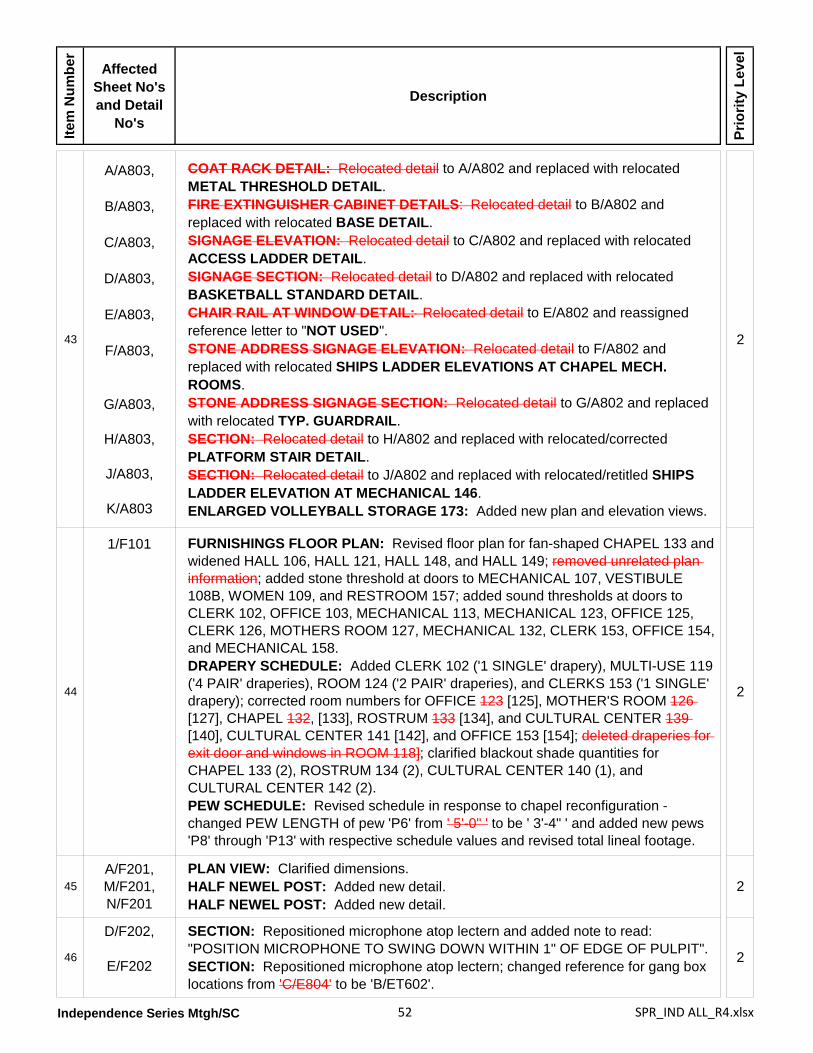
Independence Series Mtgh/SC 52 SPR_IND ALL_R4.xlsx
Item
Num
ber
Affected Sheet No's and Detail
No's
Description
Prio
rity
Leve
l
43
A/A803,
B/A803,
C/A803,
D/A803,
E/A803,
F/A803,
G/A803,
H/A803,
J/A803,
K/A803
COAT RACK DETAIL: Relocated detail to A/A802 and replaced with relocated METAL THRESHOLD DETAIL.FIRE EXTINGUISHER CABINET DETAILS: Relocated detail to B/A802 and replaced with relocated BASE DETAIL.SIGNAGE ELEVATION: Relocated detail to C/A802 and replaced with relocated ACCESS LADDER DETAIL.SIGNAGE SECTION: Relocated detail to D/A802 and replaced with relocated BASKETBALL STANDARD DETAIL.CHAIR RAIL AT WINDOW DETAIL: Relocated detail to E/A802 and reassigned reference letter to "NOT USED".STONE ADDRESS SIGNAGE ELEVATION: Relocated detail to F/A802 and replaced with relocated SHIPS LADDER ELEVATIONS AT CHAPEL MECH. ROOMS.STONE ADDRESS SIGNAGE SECTION: Relocated detail to G/A802 and replaced with relocated TYP. GUARDRAIL.SECTION: Relocated detail to H/A802 and replaced with relocated/corrected PLATFORM STAIR DETAIL.SECTION: Relocated detail to J/A802 and replaced with relocated/retitled SHIPS LADDER ELEVATION AT MECHANICAL 146.ENLARGED VOLLEYBALL STORAGE 173: Added new plan and elevation views.
2
44
1/F101 FURNISHINGS FLOOR PLAN: Revised floor plan for fan-shaped CHAPEL 133 and widened HALL 106, HALL 121, HALL 148, and HALL 149; removed unrelated plan information; added stone threshold at doors to MECHANICAL 107, VESTIBULE 108B, WOMEN 109, and RESTROOM 157; added sound thresholds at doors to CLERK 102, OFFICE 103, MECHANICAL 113, MECHANICAL 123, OFFICE 125, CLERK 126, MOTHERS ROOM 127, MECHANICAL 132, CLERK 153, OFFICE 154, and MECHANICAL 158.DRAPERY SCHEDULE: Added CLERK 102 ('1 SINGLE' drapery), MULTI-USE 119 ('4 PAIR' draperies), ROOM 124 ('2 PAIR' draperies), and CLERKS 153 ('1 SINGLE' drapery); corrected room numbers for OFFICE 123 [125], MOTHER'S ROOM 126 [127], CHAPEL 132, [133], ROSTRUM 133 [134], and CULTURAL CENTER 139 [140], CULTURAL CENTER 141 [142], and OFFICE 153 [154]; deleted draperies for exit door and windows in ROOM 118]; clarified blackout shade quantities for CHAPEL 133 (2), ROSTRUM 134 (2), CULTURAL CENTER 140 (1), and CULTURAL CENTER 142 (2).PEW SCHEDULE: Revised schedule in response to chapel reconfiguration - changed PEW LENGTH of pew 'P6' from ' 5'-0" ' to be ' 3'-4" ' and added new pews 'P8' through 'P13' with respective schedule values and revised total lineal footage.
2
45A/F201,M/F201,N/F201
PLAN VIEW: Clarified dimensions.HALF NEWEL POST: Added new detail.HALF NEWEL POST: Added new detail.
2
46
D/F202,
E/F202
SECTION: Repositioned microphone atop lectern and added note to read: "POSITION MICROPHONE TO SWING DOWN WITHIN 1" OF EDGE OF PULPIT".SECTION: Repositioned microphone atop lectern; changed reference for gang box locations from 'C/E804' to be 'B/ET602'.
2
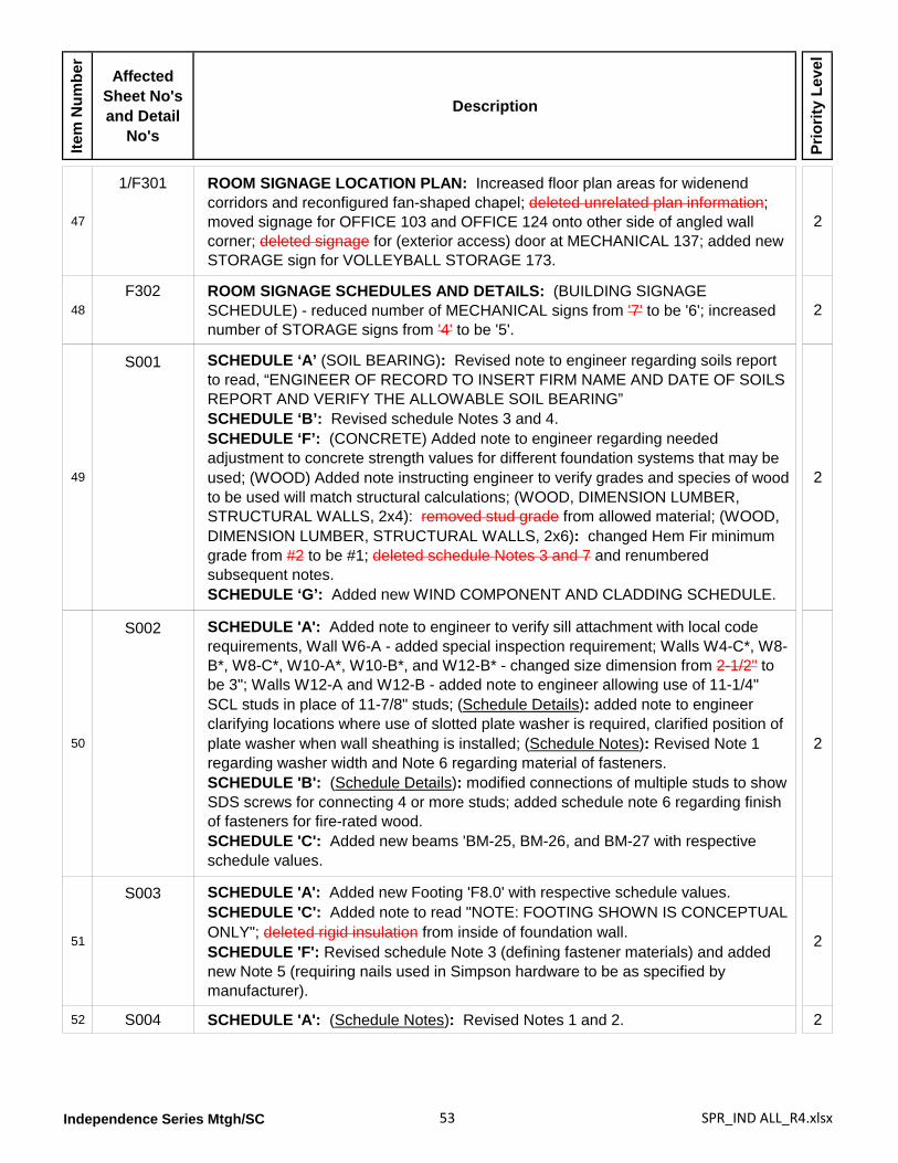
Independence Series Mtgh/SC 53 SPR_IND ALL_R4.xlsx
Item
Num
ber
Affected Sheet No's and Detail
No's
Description
Prio
rity
Leve
l
47
1/F301 ROOM SIGNAGE LOCATION PLAN: Increased floor plan areas for widenend corridors and reconfigured fan-shaped chapel; deleted unrelated plan information; moved signage for OFFICE 103 and OFFICE 124 onto other side of angled wall corner; deleted signage for (exterior access) door at MECHANICAL 137; added new STORAGE sign for VOLLEYBALL STORAGE 173.
2
48F302 ROOM SIGNAGE SCHEDULES AND DETAILS: (BUILDING SIGNAGE
SCHEDULE) - reduced number of MECHANICAL signs from '7' to be '6'; increased number of STORAGE signs from '4' to be '5'.
2
49
S001 SCHEDULE ‘A’ (SOIL BEARING): Revised note to engineer regarding soils report to read, “ENGINEER OF RECORD TO INSERT FIRM NAME AND DATE OF SOILS REPORT AND VERIFY THE ALLOWABLE SOIL BEARING”SCHEDULE ‘B’: Revised schedule Notes 3 and 4.SCHEDULE ‘F’: (CONCRETE) Added note to engineer regarding needed adjustment to concrete strength values for different foundation systems that may be used; (WOOD) Added note instructing engineer to verify grades and species of wood to be used will match structural calculations; (WOOD, DIMENSION LUMBER, STRUCTURAL WALLS, 2x4): removed stud grade from allowed material; (WOOD, DIMENSION LUMBER, STRUCTURAL WALLS, 2x6): changed Hem Fir minimum grade from #2 to be #1; deleted schedule Notes 3 and 7 and renumbered subsequent notes.SCHEDULE ‘G’: Added new WIND COMPONENT AND CLADDING SCHEDULE.
2
50
S002 SCHEDULE 'A': Added note to engineer to verify sill attachment with local code requirements, Wall W6-A - added special inspection requirement; Walls W4-C*, W8-B*, W8-C*, W10-A*, W10-B*, and W12-B* - changed size dimension from 2-1/2" to be 3"; Walls W12-A and W12-B - added note to engineer allowing use of 11-1/4" SCL studs in place of 11-7/8" studs; (Schedule Details): added note to engineer clarifying locations where use of slotted plate washer is required, clarified position of plate washer when wall sheathing is installed; (Schedule Notes): Revised Note 1 regarding washer width and Note 6 regarding material of fasteners.SCHEDULE 'B': (Schedule Details): modified connections of multiple studs to show SDS screws for connecting 4 or more studs; added schedule note 6 regarding finish of fasteners for fire-rated wood.SCHEDULE 'C': Added new beams 'BM-25, BM-26, and BM-27 with respective schedule values.
2
51
S003 SCHEDULE 'A': Added new Footing 'F8.0' with respective schedule values.SCHEDULE 'C': Added note to read "NOTE: FOOTING SHOWN IS CONCEPTUAL ONLY"; deleted rigid insulation from inside of foundation wall.SCHEDULE 'F': Revised schedule Note 3 (defining fastener materials) and added new Note 5 (requiring nails used in Simpson hardware to be as specified by manufacturer).
2
52 S004 SCHEDULE 'A': (Schedule Notes): Revised Notes 1 and 2. 2
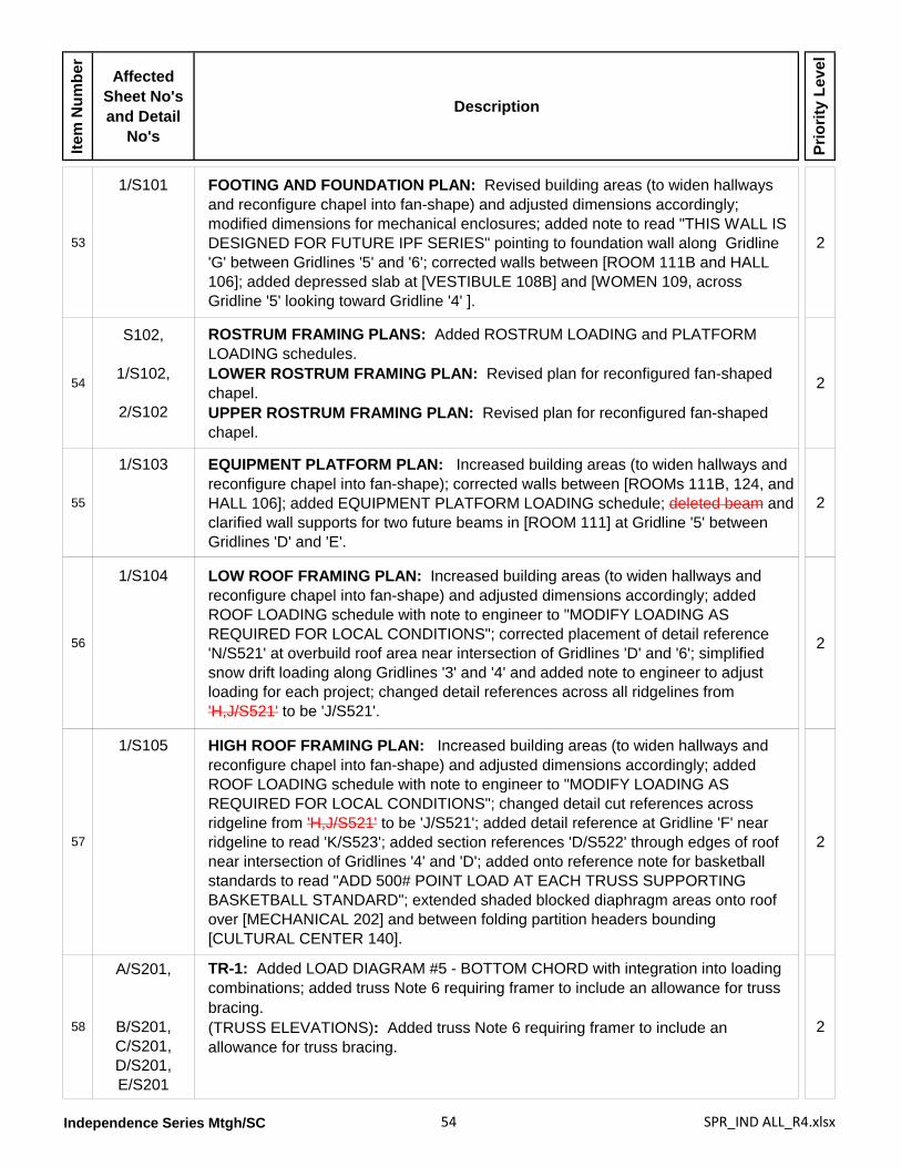
Independence Series Mtgh/SC 54 SPR_IND ALL_R4.xlsx
Item
Num
ber
Affected Sheet No's and Detail
No's
Description
Prio
rity
Leve
l
53
1/S101 FOOTING AND FOUNDATION PLAN: Revised building areas (to widen hallways and reconfigure chapel into fan-shape) and adjusted dimensions accordingly; modified dimensions for mechanical enclosures; added note to read "THIS WALL IS DESIGNED FOR FUTURE IPF SERIES" pointing to foundation wall along Gridline 'G' between Gridlines '5' and '6'; corrected walls between [ROOM 111B and HALL 106]; added depressed slab at [VESTIBULE 108B] and [WOMEN 109, across Gridline '5' looking toward Gridline '4' ].
2
54
S102,
1/S102,
2/S102
ROSTRUM FRAMING PLANS: Added ROSTRUM LOADING and PLATFORM LOADING schedules.LOWER ROSTRUM FRAMING PLAN: Revised plan for reconfigured fan-shaped chapel.UPPER ROSTRUM FRAMING PLAN: Revised plan for reconfigured fan-shaped chapel.
2
55
1/S103 EQUIPMENT PLATFORM PLAN: Increased building areas (to widen hallways and reconfigure chapel into fan-shape); corrected walls between [ROOMs 111B, 124, and HALL 106]; added EQUIPMENT PLATFORM LOADING schedule; deleted beam and clarified wall supports for two future beams in [ROOM 111] at Gridline '5' between Gridlines 'D' and 'E'.
2
56
1/S104 LOW ROOF FRAMING PLAN: Increased building areas (to widen hallways and reconfigure chapel into fan-shape) and adjusted dimensions accordingly; added ROOF LOADING schedule with note to engineer to "MODIFY LOADING AS REQUIRED FOR LOCAL CONDITIONS"; corrected placement of detail reference 'N/S521' at overbuild roof area near intersection of Gridlines 'D' and '6'; simplified snow drift loading along Gridlines '3' and '4' and added note to engineer to adjust loading for each project; changed detail references across all ridgelines from 'H,J/S521' to be 'J/S521'.
2
57
1/S105 HIGH ROOF FRAMING PLAN: Increased building areas (to widen hallways and reconfigure chapel into fan-shape) and adjusted dimensions accordingly; added ROOF LOADING schedule with note to engineer to "MODIFY LOADING AS REQUIRED FOR LOCAL CONDITIONS"; changed detail cut references across ridgeline from 'H,J/S521' to be 'J/S521'; added detail reference at Gridline 'F' near ridgeline to read 'K/S523'; added section references 'D/S522' through edges of roof near intersection of Gridlines '4' and 'D'; added onto reference note for basketball standards to read "ADD 500# POINT LOAD AT EACH TRUSS SUPPORTING BASKETBALL STANDARD"; extended shaded blocked diaphragm areas onto roof over [MECHANICAL 202] and between folding partition headers bounding [CULTURAL CENTER 140].
2
58
A/S201,
B/S201,C/S201,D/S201,E/S201
TR-1: Added LOAD DIAGRAM #5 - BOTTOM CHORD with integration into loading combinations; added truss Note 6 requiring framer to include an allowance for truss bracing.(TRUSS ELEVATIONS): Added truss Note 6 requiring framer to include an allowance for truss bracing.
2
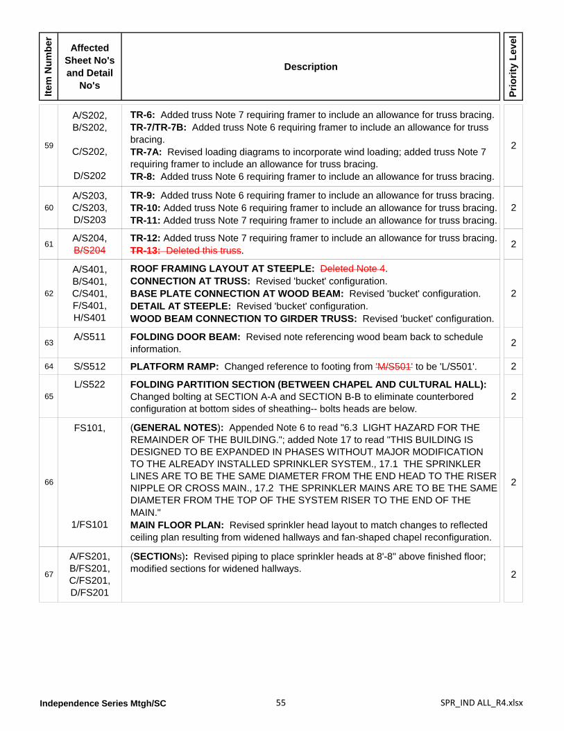
Independence Series Mtgh/SC 55 SPR_IND ALL_R4.xlsx
Item
Num
ber
Affected Sheet No's and Detail
No's
Description
Prio
rity
Leve
l
59
A/S202,B/S202,
C/S202,
D/S202
TR-6: Added truss Note 7 requiring framer to include an allowance for truss bracing.TR-7/TR-7B: Added truss Note 6 requiring framer to include an allowance for truss bracing.TR-7A: Revised loading diagrams to incorporate wind loading; added truss Note 7 requiring framer to include an allowance for truss bracing.TR-8: Added truss Note 6 requiring framer to include an allowance for truss bracing.
2
60A/S203,C/S203,D/S203
TR-9: Added truss Note 6 requiring framer to include an allowance for truss bracing.TR-10: Added truss Note 6 requiring framer to include an allowance for truss bracing.TR-11: Added truss Note 7 requiring framer to include an allowance for truss bracing.
2
61A/S204,B/S204
TR-12: Added truss Note 7 requiring framer to include an allowance for truss bracing.TR-13: Deleted this truss. 2
62
A/S401,B/S401,C/S401,F/S401,H/S401
ROOF FRAMING LAYOUT AT STEEPLE: Deleted Note 4. CONNECTION AT TRUSS: Revised 'bucket' configuration.BASE PLATE CONNECTION AT WOOD BEAM: Revised 'bucket' configuration.DETAIL AT STEEPLE: Revised 'bucket' configuration.WOOD BEAM CONNECTION TO GIRDER TRUSS: Revised 'bucket' configuration.
2
63A/S511 FOLDING DOOR BEAM: Revised note referencing wood beam back to schedule
information. 2
64 S/S512 PLATFORM RAMP: Changed reference to footing from 'M/S501' to be 'L/S501'. 2
65L/S522 FOLDING PARTITION SECTION (BETWEEN CHAPEL AND CULTURAL HALL):
Changed bolting at SECTION A-A and SECTION B-B to eliminate counterbored configuration at bottom sides of sheathing-- bolts heads are below.
2
66
FS101,
1/FS101
(GENERAL NOTES): Appended Note 6 to read "6.3 LIGHT HAZARD FOR THE REMAINDER OF THE BUILDING."; added Note 17 to read "THIS BUILDING IS DESIGNED TO BE EXPANDED IN PHASES WITHOUT MAJOR MODIFICATION TO THE ALREADY INSTALLED SPRINKLER SYSTEM., 17.1 THE SPRINKLER LINES ARE TO BE THE SAME DIAMETER FROM THE END HEAD TO THE RISER NIPPLE OR CROSS MAIN., 17.2 THE SPRINKLER MAINS ARE TO BE THE SAME DIAMETER FROM THE TOP OF THE SYSTEM RISER TO THE END OF THE MAIN."MAIN FLOOR PLAN: Revised sprinkler head layout to match changes to reflected ceiling plan resulting from widened hallways and fan-shaped chapel reconfiguration.
2
67
A/FS201,B/FS201,C/FS201,D/FS201
(SECTIONs): Revised piping to place sprinkler heads at 8'-8" above finished floor; modified sections for widened hallways. 2
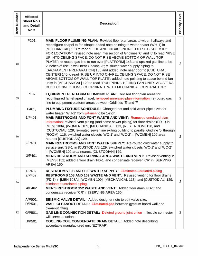
Independence Series Mtgh/SC 56 SPR_IND ALL_R4.xlsx
Item
Num
ber
Affected Sheet No's and Detail
No's
Description
Prio
rity
Leve
l
68
P101 MAIN FLOOR PLUMBING PLAN: Revised floor plan areas to widen hallways and reconfigure chapel to fan shape; added note pointing to water heater (WH-1) in [MECHANICAL] 113 to read "FLUE AND INTAKE PIPING. OFFSET- SEE M102 FOR LOCATION"; revised note near intersection of Gridlines 'C' and '6' to read "RISE UP INTO CEILING SPACE. DO NOT RISE ABOVE BOTTOM OF WALL TOP PLATE"; re-routed gas line to run over [PLATFORM] 143 and upsized gas line to be 2 inches at rise in wall near Gridline '3'; re-routed water supply piping to [SACRAMENT PREPARATION] 135 and added note near door to [CULTURAL CENTER] 140 to read "RISE UP INTO CHAPEL CEILING SPACE. DO NOT RISE ABOVE BOTTOM OF WALL TOP PLATE"; added note pointing to space behind fan units in [MECHANICAL] 120 to read "RUN PIPING BEHIND FAN UNITS ABOVE RA DUCT CONNECTIONS. COORDINATE WITH MECHANICAL CONTRACTOR".
2
69P102 EQUIPMENT PLATFORM PLUMBING PLAN: Revised floor plan areas for
reconfigured fan-shaped chapel; removed unrelated plan information; re-routed gas line to equipment platform areas between Gridlines 'E' and 'F'.
2
70
P401,
1/P401,
2/P401,
3/P401
PLUMBING FIXTURE SCHEDULE: Changed hot and cold water pipe sizes for water heater 'WH-1' from 3/4 inch to be 1-inch.MAIN RESTROOMS AND FONT WASTE AND VENT: Removed unrelated plan information; revised vent piping (and some sewer piping) for floor drains (FD-1) in [MEN] 108A, [WOMEN] 109, [MECHANICAL] 113, [REST ROOM] 128, and [CUSTODIAL] 129; re-routed sewer line exiting building to parallel Gridline '5' through [ROOM] 116; switched water closets 'WC-1' and 'WC-2' in [WOMEN] 109 area nearest [CUSTODIAN] 129.MAIN RESTROOMS AND FONT WATER SUPPLY: Re-routed cold water supply to service sink 'SS-1' in [CUSTODIAN] 129; switched water closets 'WC-1' and 'WC-2' in [WOMEN] 109 area nearest [CUSTODIAN] 129.MENS RESTROOM AND SERVING AREA WASTE AND VENT: Revised venting in [MENS] 152; added a floor drain 'FD-1' and condensate receiver 'CR' in [SERVING AREA] 150.
2
71
1/P402,2/P402,
4/P402
RESTROOMS 108 AND 109 WATER SUPPLY: Eliminated unrelated piping.RESTROOMS 108 AND 109 WASTE AND VENT: Revised venting for floor drains (FD-1) in [MEN 108A], [WOMEN 109], [MECHANICAL 113], and [CUSTODIAL] 129; eliminated unrelated piping.MEN'S RESTROOM 152 WASTE AND VENT: Added floor drain 'FD-1' and condensate receiver 'CR' in [SERVING AREA 150].
2
72
A/P501,D/P501,
G/P501,
J/P501
SEISMIC VALVE DETAIL: Added designer note to edit valve size.WALL CLEANOUT DETAIL: Eliminated gap between gypsum board wall and cleanout fitting.GAS LINE CONNECTION DETAIL: Deleted ground joint union— flexible connector will serve as union.COOLING COIL CONDENSATE DRAIN DETAIL: Added note describing acceptable manufactured unit (EZTRAP).
2
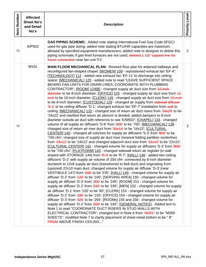
Independence Series Mtgh/SC 57 SPR_IND ALL_R4.xlsx
Item
Num
ber
Affected Sheet No's and Detail
No's
Description
Prio
rity
Leve
l
73A/P502
GAS PIPING SCHEME: Added note stating International Fuel Gas Code (IFGC) used for gas pipe sizing; added note stating BTU/HR capacities are maximum allowed by specified equipment manufacturers; added note to designer to delete this piping schematic if gas-fired furnaces are not used; deleted 1 1/2" capped line for future connection near fan unit 'F2'.
2
74
M101 MAIN FLOOR MECHANICAL PLAN: Revised floor plan for widened hallways and reconfigured fan-shaped chapel; [WOMEN] 109 - repositioned exhaust fan 'EF-4''; [TECHNOLOGY] 112 - added new exhaust fan 'EF-11' to discharge into ceiling space; [MECHANICAL] 120 - added note to read "LEAVE SUFFICIENT SPACE BEHIND FAN UNITS FOR DRAIN LINES. COORDINATE WITH PLUMBING CONTRACTOR"; [ROOM] 124[B] - changed supply air duct size from 10-inch diameter to be 8-inch diameter; [OFFICE] 125 - changed supply air duct size from 12-inch to be 10-inch diameter; [CLERK] 126 - changed supply air duct size from 10-inch to be 8-inch diameter; [CUSTODIAL] 129 - changed air supply from sidewall diffuser 'S-1' to be ceiling diffuser 'D-1'; changed exhaust fan 'EF-7' installation from wall to ceiling; [MECHANICAL] 132 - changed size of return air duct risers from '16x20' to be '16x22' and clarified that return air plenum is divided, added dampers to 8-inch diameter outside air duct with reference to see 'E/M502'; [CHAPEL] 133 - changed volume of all supply air diffusers 'D-6' from '800' to be '700'; [MECHANICAL] 138 - changed size of return air riser duct from '30x14' to be '16x22'; [CULTURAL CENTER] 140 - changed all volumes for supply air diffusers 'S-3' from '800' to be '700 cfm', changed size of supply air duct riser (nearest folding partition centerline) from '16x12' to be '18x12' and changed adjacent duct size from '16x10' to be '22x10'; [CULTURAL CENTER] 142 - changed volume for supply air diffusers 'S-3' from '800' to be '700 cfm'; [PLATFORM] 143 - changed sidewall return air register (in wall shared with STORAGE 144) from 'R-9' to be 'R-7'; [HALL] 148 - added two ceiling diffusers 'D-2' with supply air volume of 200 cfm connected by 8-inch diameter ductwork to 12x8 supply air duct (transitioned to 8x8 duct) and originating from (upsized) 22x10 main duct, changed volume for supply air diffuser 'D-3' (near VESTIBULE 147) from '285' to be '235'; [HALL] 149 - changed volume for supply air diffuser 'D-2' from '120' to be '100'; [SERVING AREA] 150 - changed volume for supply air diffuser 'D-3' from '300' to be '245'; [ROOM] 151 - changed volume for supply air diffuser 'D-2' from '240' to be '195'; [MEN] 152 - changed volume for supply
2
air diffuser 'D-1' from '100' to be '80'; [CLERK] 153 - changed volume for supply air diffuser 'D-2' from '180' to be '150'; [OFFICE] 154 - changed volume for supply air diffuser 'D-3' from '325' to be '265'; [ROOMs] 155 and 156 - changed volume for supply air diffuser 'D-2' from '200' to be '165'; (GENERAL NOTES): Added text to Note 1 to read "COORDINATE DUCT RISERS IN STUD WALLS WITH ELECTRICAL CONTRACTOR"; changed text in Note 6 from "M301" to be "M300 SHEETS"; modified Note 7 to clarify placement of sheet metal bottom to be " 8" FROM ABOVE FINISH CEILING..."
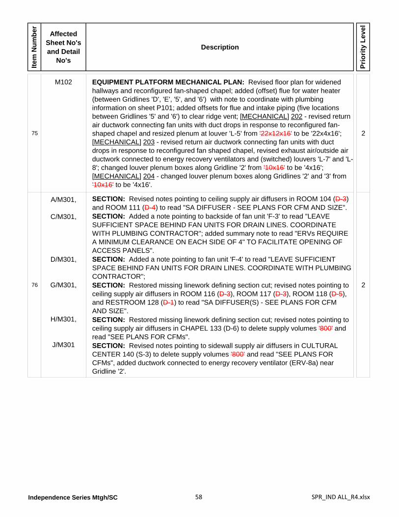
Independence Series Mtgh/SC 58 SPR_IND ALL_R4.xlsx
Item
Num
ber
Affected Sheet No's and Detail
No's
Description
Prio
rity
Leve
l
75
M102 EQUIPMENT PLATFORM MECHANICAL PLAN: Revised floor plan for widened hallways and reconfigured fan-shaped chapel; added (offset) flue for water heater (between Gridlines 'D', 'E', '5', and '6') with note to coordinate with plumbing information on sheet P101; added offsets for flue and intake piping (five locations between Gridlines '5' and '6') to clear ridge vent; [MECHANICAL] 202 - revised return air ductwork connecting fan units with duct drops in response to reconfigured fan-shaped chapel and resized plenum at louver 'L-5' from '22x12x16' to be '22x4x16'; [MECHANICAL] 203 - revised return air ductwork connecting fan units with duct drops in response to reconfigured fan shaped chapel, revised exhaust air/outside air ductwork connected to energy recovery ventilators and (switched) louvers 'L-7' and 'L-8'; changed louver plenum boxes along Gridline '2' from '10x16' to be '4x16'; [MECHANICAL] 204 - changed louver plenum boxes along Gridlines '2' and '3' from '10x16' to be '4x16'.
2
76
A/M301,
C/M301,
D/M301,
G/M301,
H/M301,
J/M301
SECTION: Revised notes pointing to ceiling supply air diffusers in ROOM 104 (D-3) and ROOM 111 (D-4) to read "SA DIFFUSER - SEE PLANS FOR CFM AND SIZE".SECTION: Added a note pointing to backside of fan unit 'F-3' to read "LEAVE SUFFICIENT SPACE BEHIND FAN UNITS FOR DRAIN LINES. COORDINATE WITH PLUMBING CONTRACTOR"; added summary note to read "ERVs REQUIRE A MINIMUM CLEARANCE ON EACH SIDE OF 4" TO FACILITATE OPENING OF ACCESS PANELS".SECTION: Added a note pointing to fan unit 'F-4' to read "LEAVE SUFFICIENT SPACE BEHIND FAN UNITS FOR DRAIN LINES. COORDINATE WITH PLUMBING CONTRACTOR"; SECTION: Restored missing linework defining section cut; revised notes pointing to ceiling supply air diffusers in ROOM 116 (D-3), ROOM 117 (D-3), ROOM 118 (D-5), and RESTROOM 128 (D-1) to read "SA DIFFUSER(S) - SEE PLANS FOR CFM AND SIZE".SECTION: Restored missing linework defining section cut; revised notes pointing to ceiling supply air diffusers in CHAPEL 133 (D-6) to delete supply volumes '800' and read "SEE PLANS FOR CFMs".SECTION: Revised notes pointing to sidewall supply air diffusers in CULTURAL CENTER 140 (S-3) to delete supply volumes '800' and read "SEE PLANS FOR CFMs", added ductwork connected to energy recovery ventilator (ERV-8a) near Gridline '2'.
2
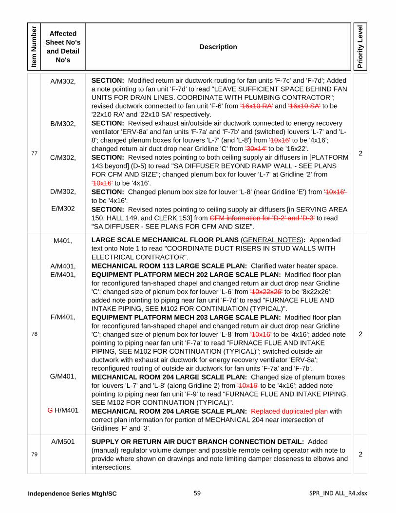
Independence Series Mtgh/SC 59 SPR_IND ALL_R4.xlsx
Item
Num
ber
Affected Sheet No's and Detail
No's
Description
Prio
rity
Leve
l
77
A/M302,
B/M302,
C/M302,
D/M302,
E/M302
SECTION: Modified return air ductwork routing for fan units 'F-7c' and 'F-7d'; Added a note pointing to fan unit 'F-7d' to read "LEAVE SUFFICIENT SPACE BEHIND FAN UNITS FOR DRAIN LINES. COORDINATE WITH PLUMBING CONTRACTOR"; revised ductwork connected to fan unit 'F-6' from '16x10 RA' and '16x10 SA' to be '22x10 RA' and '22x10 SA' respectively.SECTION: Revised exhaust air/outside air ductwork connected to energy recovery ventilator 'ERV-8a' and fan units 'F-7a' and 'F-7b' and (switched) louvers 'L-7' and 'L-8'; changed plenum boxes for louvers 'L-7' (and 'L-8') from '10x16' to be '4x16'; changed return air duct drop near Gridline 'C' from '30x14' to be '16x22'.SECTION: Revised notes pointing to both ceiling supply air diffusers in [PLATFORM 143 beyond] (D-5) to read "SA DIFFUSER BEYOND RAMP WALL - SEE PLANS FOR CFM AND SIZE"; changed plenum box for louver 'L-7' at Gridline '2' from '10x16' to be '4x16'.SECTION: Changed plenum box size for louver 'L-8' (near Gridline 'E') from '10x16' to be '4x16'.SECTION: Revised notes pointing to ceiling supply air diffusers [in SERVING AREA 150, HALL 149, and CLERK 153] from CFM information for 'D-2' and 'D-3' to read "SA DIFFUSER - SEE PLANS FOR CFM AND SIZE".
2
78
M401,
A/M401,E/M401,
F/M401,
G/M401,
G H/M401
LARGE SCALE MECHANICAL FLOOR PLANS (GENERAL NOTES): Appended text onto Note 1 to read "COORDINATE DUCT RISERS IN STUD WALLS WITH ELECTRICAL CONTRACTOR".MECHANICAL ROOM 113 LARGE SCALE PLAN: Clarified water heater space.EQUIPMENT PLATFORM MECH 202 LARGE SCALE PLAN: Modified floor plan for reconfigured fan-shaped chapel and changed return air duct drop near Gridline 'C'; changed size of plenum box for louver 'L-6' from '10x22x26' to be '8x22x26'; added note pointing to piping near fan unit 'F-7d' to read "FURNACE FLUE AND INTAKE PIPING, SEE M102 FOR CONTINUATION (TYPICAL)".EQUIPMENT PLATFORM MECH 203 LARGE SCALE PLAN: Modified floor plan for reconfigured fan-shaped chapel and changed return air duct drop near Gridline 'C'; changed size of plenum box for louver 'L-8' from '10x16' to be '4x16'; added note pointing to piping near fan unit 'F-7a' to read "FURNACE FLUE AND INTAKE PIPING, SEE M102 FOR CONTINUATION (TYPICAL)"; switched outside air ductwork with exhaust air ductwork for energy recovery ventilator 'ERV-8a'; reconfigured routing of outside air ductwork for fan units 'F-7a' and 'F-7b'.MECHANICAL ROOM 204 LARGE SCALE PLAN: Changed size of plenum boxes for louvers 'L-7' and 'L-8' (along Gridline 2) from '10x16' to be '4x16'; added note pointing to piping near fan unit 'F-9' to read "FURNACE FLUE AND INTAKE PIPING, SEE M102 FOR CONTINUATION (TYPICAL)".MECHANICAL ROOM 204 LARGE SCALE PLAN: Replaced duplicated plan with correct plan information for portion of MECHANICAL 204 near intersection of Gridlines 'F' and '3'.
2
79
A/M501 SUPPLY OR RETURN AIR DUCT BRANCH CONNECTION DETAIL: Added (manual) regulator volume damper and possible remote ceiling operator with note to provide where shown on drawings and note limiting damper closeness to elbows and intersections.
2
Independence Series Mtgh/SC 60 SPR_IND ALL_R4.xlsx
Item
Num
ber
Affected Sheet No's and Detail
No's
Description
Prio
rity
Leve
l
80
B/M502,C/M502,
E/M502,F/M502
FAN UNIT SUPPORT DETAILS: Reoriented detail components for clarity.CONCENTRIC ROOF TERMINATION DETAIL: Added note to designer to delete this detail if gas fired furnaces are not used.TYPICAL OUTSIDE AIR DUCT DETAIL: Reoriented detail for clarity.CHAPEL RETURN AIR PLENUM: Changed dimensions.
2
81M503 REFRIGERANT LINE SIZES (schedule): Revised schedule to be based on
compressor unit sizes. 2
82
M601 MECHANICAL SCHEDULES: Added DESIGN CONDITIONS schedule.EXHAUST FAN SCHEDULE: Relocated schedule to sheet M602.FURNACE [FAN UNIT] SCHEDULE [(GAS FIRED FURNACE)]: Retitled schedule; changed "MIN. REQ'D OUTPUT BTU/HR" schedule values for fan units 'F-7a', 'F-7b', 'F-7c', 'F-7d', 'F-8a', 'F-8b', and 'F-11'; changed "MINIMUM A.C.F.M." schedule values for fan units 'F-6', 'F-7a', 'F-7b', 'F-7c', 'F-7d', 'F-8a', F-8b', 'F-9' and 'F-11'; changed "MIN. OUTSIDE AIR CFM" schedule values for fan units 'F-1', 'F-3', and 'F-6'; changed "MOTOR/MINIMUM H.P." schedule value for fan unit 'F-11'; changed "MOTOR/SPEED' schedule value for fan unit 'F-11'.CONDENSING [COMPRESSOR] UNIT SCHEDULE [(COMPRESSOR)]: Retitled schedule; added new columns labeled "MIN. CIRCUIT AMPS" and "MOCP" with relevant values; revised multiple schedule values for all condensing units except 'CU-3', 'CU-5', and 'CU-10'.DX COIL SCHEDULE: Significantly changed schedule values for all (direct expansion) condenser coils.ENERGY RECOVERY VENTILATOR schedule: Changed "CFM' schedule values for energy recovery ventilators 'ERV-3', 'ERV-8a', and 'ERV-8b'; added new schedule Note 3 to reference schedule MARK and read "ENERGY RECOVERY VENTILATOR MARKS CORRESPOND WITH FAN UNIT MARKS".ELECTRIC WALL HEATER SCHEDULE: Removed 'revision cloud'.
2
Independence Series Mtgh/SC 61 SPR_IND ALL_R4.xlsx
Item
Num
ber
Affected Sheet No's and Detail
No's
Description
Prio
rity
Leve
l
83
M602 DIFFUSER SCHEDULE (C.F.M. RANGE): Changed upper value for diffuser 'D-2' from 220 to be 200; changed lower value for diffuser 'D-3' from 225 to be 205; changed schedule note for diffuser 'D-6' (C.F.M. RANGE) from '12' to be '13'.REGISTER, LOUVER, & GRILLE SCHEDULE: Deleted sidewall register 'R-10' and soffit grille 'SG-1'; (CFM RANGE): changed schedule values for sidewall registers 'R-5', 'R-6', 'R-7', sidewall grille 'S-3', and louvers 'L-1' and 'L-3'; (NOMINAL SIZE): changed schedule value for register 'R-4' from '30x30' to be '30x28'; (REMARKS): ceiling registers 'R-1', 'R-3' and 'R-4' - deleted schedule Note '9', ceiling transfer grille 'T-1' - added schedule Note '7', louvers 'L-3' and 'L-4' - changed schedule Note from '13' to be Note '12'; (SCHEDULE NOTES): switched text between Notes 12 and 13.EXHAUST FAN SCHEDULE: Relocated schedule from sheet M601; (MIN. S.C.F.M.) - changed schedule values for exhaust fans 'EF-1', 'EF-2', 'EF-4', and 'EF-9'; (MINIMUM WATTS) - changed schedule values for exhaust fans 'EF-1', 'EF-2', 'EF-4', and 'EF-9'; removed schedule Note 4 from exhaust fan 'EF-9'; added new exhaust fan 'EF-11' for TECHNOLOGY 112 with following schedule values: MIN. S.C.F.M. = 300, STATIC PRESSURE IN W.G.= 0.15, MINIMUM WATTS = 210W, provided with a back-draft damper, and referenced by revised schedule Note 4 that now reads, "DISCHARGE IN CEILING SPACE. CONTROL WITH LINE VOLTAGE THERMOSTAT. ACCESSORY THERMOSTAT BY DIV. 23, INSTALLED BY DIV. 26".
2
84
ME101 MAIN FLOOR PLAN: Modified floor plan for widened hallways and reconfigured fan-shaped chapel; removed unrelated plan information; added new exhaust fan 'EF-11' with line voltage thermostat 'T2' in [TECHNOLOGY 112]; added designation of 'S-1' to remote sensors in [ROOM] 104, [ROOM] 124, and [ROOM] 155; added designation of 'S-2' to remote sensors in [OFFICE] 103, [OFFICE] 125, and [OFFICE] 154; deleted humidity sensor from [CHAPEL] 133 and [CULTURAL CENTER] 140; clarified remote sensor outlet in [MULTI-USE] 119 to be associated with fan unit 'F-3'; added remote sensor outlet in [ROOM] 117 for fan unit 'F-4'; added webstat in [ELECTRICAL] 114.EQUIPMENT PLATFORM MECHANICAL PLAN: Modified floor plan for widened hallways and reconfigured fan-shaped chapel; removed unrelated plan information; clarified thermostat in [MECHANICAL] 204 to be associated with fan unit 'F-9'; changed relay panel designations in [MECHANICAL] 203 from 'RP-1' and 'RP-5' to both be 'RP-6'.SYMBOLS legend: Expanded thermostat symbol description to include new line voltage thermostat 'T2'; appended text to remote sensor outlet description to read "COORDINATE LOCATION WITH CHALKBOARD"; changed symbol for relay panel from 'RP-5' to be 'RP-6'; deleted symbol and and information for humidity sensor.
2
Independence Series Mtgh/SC 62 SPR_IND ALL_R4.xlsx
Item
Num
ber
Affected Sheet No's and Detail
No's
Description
Prio
rity
Leve
l
85
ME201,
A/ME201
CONTROL EQUIPMENT (schedule): Changed catalog number of transformer 'X-2' from 'AT150F1002' to be 'AT150F1022'; changed catalog number for two pole relay 'RIB' from 'RIBU1C' to be 'RIB2401D'; added schedule information for new line voltage thermostat 'T2' to be provided by specification Division 23 and installed by Division 26; changed relay panel designation from 'RP-5' to be 'RP-6' with size changed from '18x18x6' to be 24x18x6; deleted schedule information for relay panel 'RP-1'.WIRING DIAGRAM: Changed wire colors in cable connecting thermostat 'T-1' and fan unit from black to green and from brown to orange; added CO2 sensor connected to fan unit and transformer 'X-2' with one 8-conductor cable; added note pointing to damper motor 'DM-2' clarifying use of wire nut connector splices in box for two 4-conductor cables connecting associated fan unit and energy recovery ventilator.ENERGY RECOVERY VENTILATOR WIRING: Combined white and blue wires connecting damper motors 'DM-1' or 'DM-2' with energy recovery ventilator into one 4 conductor cable; removed note regarding 'F-7' and 'F-9' systems; removed 'X-2' designation from bottom transformer.
2
86
ME202 WIRING DIAGRAM: Eliminated smoke detectors for fan units "b" and "d" and connected these fan units into shared smoke detectors for fan units "a" and "b" respectively; changed designation of relay panel from 'RP-5' to be 'RP-6'; removed all '#16 RED JUMPER' information from within relay panel 'RP-6'; added CO2 sensor wired correctly into relay panel 'RP-6''; defined power source at switch for fan unit "d" to be '120V 1PHZ 60HZ'; changed responsibility to provide fan unit switches from 'DIVISION 16' to be 'DIVISION 26'.
2
87
M203 WIRING DIAGRAM: Clarified energy recovery ventilator for fan units "a" and "b" to be 'ERV "A" ' and 'ERV "B" ' respectively; removed color designations for wires connecting each damper motor 'DM-2' and related energy recovery ventilator; clarified reference notes for energy recovery ventilator wiring connections to refer to DETAIL A/ME201; added CO2 sensor wired correctly into relay panel 'RP-6'; changed responsibility to provide fan unit switches from 'DIVISION 16' to be 'DIVISION 26'.
2
88
E101,E102,E103,E501,E601,E602,E701,
FA101,LP101
ELECTRICAL DRAWINGS: Replaced all listed electrical drawing sheets with new replacement electrical drawing sheets significantly corrected and updated with changes including but not be limited to: revised layouts for lighting fixtures, circuiting, switches, outlets; corrected plan notes; moved data and phone outlet information to sound drawings; added exhaust fan in TECHNOLOGY 112; moved Panel ‘A’ to opposite wall of MATERIAL CENTER 105; coordinated exhaust fan references and mechanical equipment locations; corrected Lighting Fixture schedules, Equipment schedules, Panel and Load Center schedules, Single Line Diagrams, and Fire Riser Diagrams; corrected Storage Building Electrical Plan; corrected Lightning Protection Plan; corrected Compressor Unit and Dimmer Switch details.
2
Independence Series Mtgh/SC 63 SPR_IND ALL_R4.xlsx
Item
Num
ber
Affected Sheet No's and Detail
No's
Description
Prio
rity
Leve
l
89
E801,E802,
E803,
E804,TA600,TA601,TA602,TA603,TA604
SOUND SYSTEM DRAWINGS: Sound system information has been reorganized and coordinated upon the following renumbered sheets:ELECTRICAL EQUIPMENT LIST AND DETAILS: Renumbered to be ET601.MICROPHONE, VIDEO, [FLOOR PLAN A/V] AND DATA LAYOUT: Retitled and renumbered to be ET101.SPEAKER [REFLECTED CEILING A/V AND DATA] LAYOUT: Retitled and renumbered to be ET102.ELECTRICAL DETAILS: Renumbered to be ET602.AUDIO, VIDEO, AND DATA DETAILS: Renumbered to be TA602.AUDIO RISER: Renumbered to be TA603.VIDEO RISER: Renumbered to be TA604.DATA RISER: Renumbered to be TA605.AUDIO, VIDEO, AND DATA EQUIPMENT LIST: Renumbered to be TA601.
2
Independence 230SC Stake Center [IPE-SC-10-04]
1
G101
(Building Elevation) - Added new front elevation view.DRAWING INDEX: Renumbered and rearranged sound drawings-- see related SOUND SYSTEM DRAWINGS item below; modified note in bottom left corner to delete reference to "drawings on a CD"; clarified following option sheet listings in bottom portion of index: C705 - SITE CIVIL DETAILS FOR PERVIOUS CONCRETE GROUND WATER RECHARGEABLE BED, C706 - SITE CIVIL DETAILS FOR PERVIOUS CONCRETE GROUND WATER RECHARGEABLE BED, and LP101a - LIGHTNING PROTECTION PLAN.DESIGN CRITERIA schedule: Corrected design temperatures reference to ASHRAE from '62-2001' to be '62-2007'.
2
21/G102 OCCUPANCY PLAN: Revised building square footage from '18,657' to be '18,742
sf' to account for widened halls and reconfigured fan-shaped chapel. 2
3
C701,
B/C701,
K/C701,
L/C701,
[G]/C701
SITE CIVIL DETAILS: Moved SITE OBSERVATIONS BY CIVIL ENGINEER to new informational sheet C000 and rearranged sheet layout.(INTEGRAL) SIDEWALK, CURB AND GUTTER: Encompassed both 'B' details within a single 'cloud' and added instructions to engineer to "SELECT APPROPRIATE DETAIL THEN DELETE DETAIL NOT USED AND THIS NOTE".ASPHALT PAVING: Added text onto note to engineer to read "ASPHALT PAVING: 3" MINIMUM, AGGREGATE BASE: 6" MINIMUM".CONCRETE PAVING: Added text onto note to engineer to read "CONCRETE PAVING: 4" MINIMUM, AGGREGATE BASE: 4" MINIMUM".EXPANSION AND CONTROL JOINT: Relocated this detail to M/C702.
2
4
C702,
A/C702,
M/C702
SITE CIVIL DETAILS: Removed CONCRETE PAVING NOTES WHERE CONCRETE PAVING IS USED.HANDICAPPED ACCESSIBLE PARKING SIGN (TRAFFIC SIGNAGE): Replaced detail with new replacement detail.EXPANSION AND CONTROL JOINT: Added relocated detail.
2
5 L/C703 STOP & WASTE VALVE DETAIL: Added new detail. 2
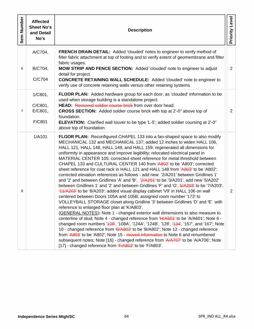
Independence Series Mtgh/SC 64 SPR_IND ALL_R4.xlsx
Item
Num
ber
Affected Sheet No's and Detail
No's
Description
Prio
rity
Leve
l
6
A/C704,
B/C704,
C/C704
FRENCH DRAIN DETAIL: Added 'clouded' notes to engineer to verify method of filter fabric attachment at top of footing and to verify extent of geomembrane and filter fabric usages.MOW STRIP AND FENCE SECTION: Added 'clouded' note to engineer to adjust detail for project.CONCRETE RETAINING WALL SCHEDULE: Added 'clouded' note to engineer to verify use of concrete retaining walls versus other retaining systems.
2
7
1/C801,
C/C801,E/C801,
F/C801
FLOOR PLAN: Added hardware group for each door, as 'clouded' information to be used when storage building is a standalone project.HEAD: Removed soldier course brick from over door head.CROSS SECTION: Added soldier course brick with top at 2'-0" above top of foundation.ELEVATION: Clarified wall louver to be type 'L-5'; added soldier coursing at 2'-0" above top of foundation.
2
8
1/A101 FLOOR PLAN: Reconfigured CHAPEL 133 into a fan-shaped space to also modify MECHANICAL 132 and MECHANICAL 137; added 12 inches to widen HALL 106, HALL 121, HALL 148, HALL 149, and HALL 159; regenerated all dimensions for uniformity in appearance and improve legibility; relocated electrical panel in MATERIAL CENTER 105; corrected sheet reference for metal threshold between CHAPEL 133 and CULTURAL CENTER 140 from 'A802' to be 'A803'; corrected sheet reference for coat rack in HALL 121 and HALL 148 from 'A803' to be 'A802'; corrected elevation references as follows - add new '2/A201' between Gridlines 1' and '2' and between Gridlines 'A' and 'B', '2/A201' to be '3/A201', add new '5/A202' between Gridlines 1' and '2' and between Gridlines 'F' and 'G', 5/A203' to be '7/A203', '11/A203' to be '8/A203'; added visual display cabinet 'V9' in HALL 106 on wall centered between Doors 105A and 105B; assigned room number '173' to VOLLEYBALL STORAGE closet along Gridline '3' between Gridlines 'D' and 'E' with reference to enlarged floor plan at 'K/A803'.(GENERAL NOTES): Note 1 - changed exterior wall dimensions to also measure to centerline of stud; Note 4 - changed reference from 'H/A601' to be 'A/A601'; Note 6 - changed room numbers '108', '108A', '124A', '124B', '128', '134', '157', and '167'; Note 10 - changed reference from 'B/A803' to be 'B/A802'; Note 12 - changed reference from 'A803' to be 'A802'; Note 15 - moved information to Note 6 and renumbered subsequent notes; Note [16] - changed reference from 'A/A707' to be 'A/A706'; Note [17] - changed reference from 'F/A802' to be 'F/A803'.
2
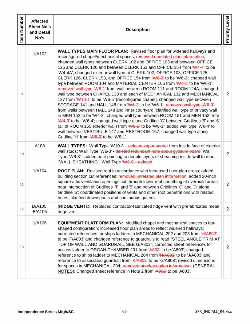
Independence Series Mtgh/SC 65 SPR_IND ALL_R4.xlsx
Item
Num
ber
Affected Sheet No's and Detail
No's
Description
Prio
rity
Leve
l
9
1/A102 WALL TYPES MAIN FLOOR PLAN: Revised floor plan for widened hallways and reconfigured chapel/mechanical spaces; removed unrelated plan information; changed wall types between CLERK 102 and OFFICE 103 and between OFFICE 125 and CLERK 126 and between CLERK 153 and OFFICE 154 from 'W4-4' to be 'W4-4A'; changed exterior wall type at CLERK 102, OFFICE 103, OFFICE 125, CLERK 126, CLERK 153, and OFFICE 154 from 'W6-3' to be 'W6-2'; changed wall type between ROOM 104 and MATERIAL CENTER 105 from 'W4-1' to be 'W6-1'; removed wall type 'W8-1' from wall between ROOM 111 and ROOM 124A; changed wall type between CHAPEL 133 and each of MECHANICAL 132 and MECHANICAL 137 from 'W10-1' to be 'W6-5' (reconfigured chapel); changed wall type between STORAGE 141 and HALL 148 from 'W6-2' to be 'W6-1'; removed wall type 'W6-9' from walls between HALL 148 and inner courtyard; clarified wall type of privacy wall in MEN 152 to be 'W4-3'; changed wall type between ROOM 151 and MEN 152 from 'W4-3' to be 'W6-4'; changed wall type along Gridline 'G' between Gridlines '5' and '6' (all of ROOM 155 exterior wall) from 'W8-2' to be 'W8-1'; added wall type 'W6-4' to wall between VESTIBULE 147 and RESTROOM 167; changed wall type along Gridline 'H' from 'W8-2' to be 'W8-1'.
2
10
A103 WALL TYPES: Wall Type 'W10-3' - deleted vapor barrier from inside face of exterior wall studs; Wall Type 'W6-3' - deleted redundant note about gypsum board; Wall Type 'W6-8' - added note pointing to double layers of sheathing inside wall to read "WALL SHEATHING"; Wall Type 'W6-9' - deleted.
2
11
1/A104 ROOF PLAN: Revised roof in accordance with increased floor plan areas; added building section cut references; removed unrelated plan information; added 20-inch square attic ventilation openings cut through lower roof sheathing at overbuild areas near intersection of Gridlines 'F' and '5' and between Gridlines 'C' and 'D' along Gridline '5'; coordinated positions of vents and other roof penetrations with related notes; clarified downspouts and continuous gutters.
2
12D/A105,E/A105
(RIDGE VENTs): Replaced contractor-fabricated ridge vent with prefabricated metal ridge vent. 2
13
1/A106 EQUIPMENT PLATFORM PLAN: Modified chapel and mechanical spaces to fan-shaped configuration; increased floor plan areas to reflect widened hallways; corrected references for ships ladders to MECHANICAL 202 and 203 from 'H/A802' to be 'F/A803' and changed reference to guardrails to read "STEEL ANGLE TRIM AT TOP OF WALL AND GUARDRAIL, SEE G/A802"; corrected sheet references for access ladder to ORGAN CHAMBER 201 from 'A802' to be 'A803'; changed reference to ships ladder to MECHANICAL 204 from 'N/A802' to be 'J/A803' and reference to associated guardrail from 'K/A802' to be 'G/A803'; revised dimensions for spaces in MECHANICAL 204; removed unrelated plan information; (GENERAL NOTES): Changed sheet reference in Note 2 from 'A802' to be 'A803'.
2
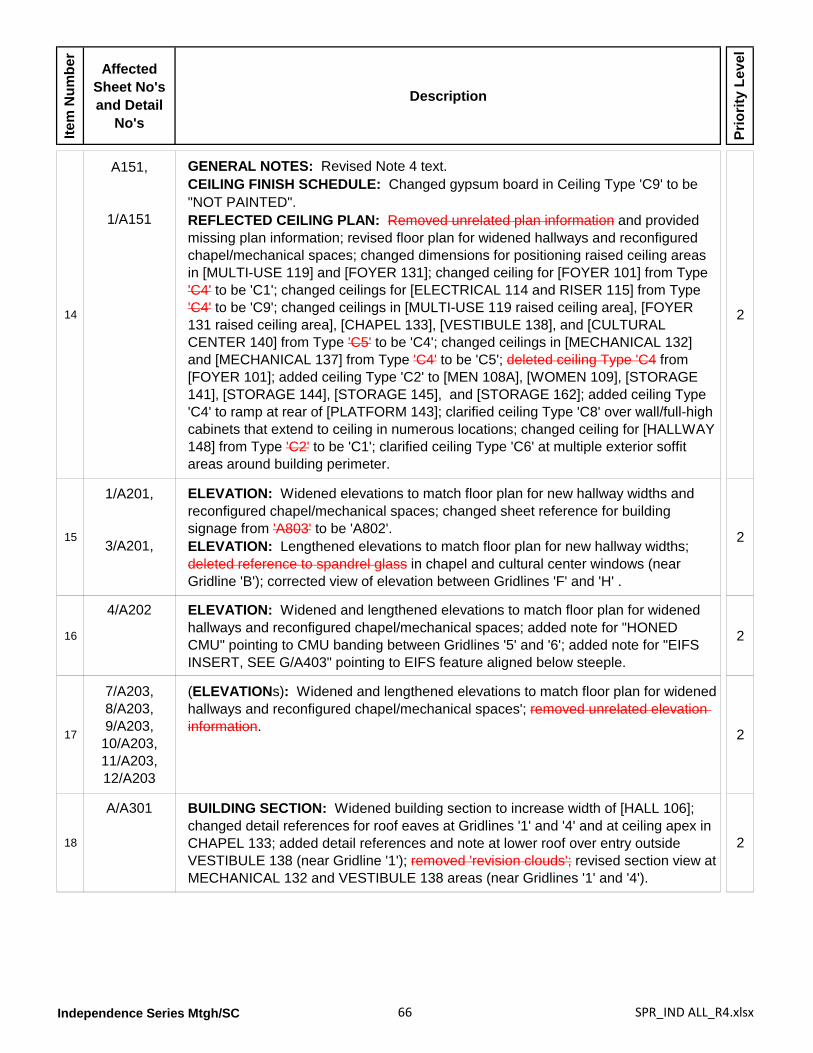
Independence Series Mtgh/SC 66 SPR_IND ALL_R4.xlsx
Item
Num
ber
Affected Sheet No's and Detail
No's
Description
Prio
rity
Leve
l
14
A151,
1/A151
GENERAL NOTES: Revised Note 4 text.CEILING FINISH SCHEDULE: Changed gypsum board in Ceiling Type 'C9' to be "NOT PAINTED".REFLECTED CEILING PLAN: Removed unrelated plan information and provided missing plan information; revised floor plan for widened hallways and reconfigured chapel/mechanical spaces; changed dimensions for positioning raised ceiling areas in [MULTI-USE 119] and [FOYER 131]; changed ceiling for [FOYER 101] from Type 'C4' to be 'C1'; changed ceilings for [ELECTRICAL 114 and RISER 115] from Type 'C4' to be 'C9'; changed ceilings in [MULTI-USE 119 raised ceiling area], [FOYER 131 raised ceiling area], [CHAPEL 133], [VESTIBULE 138], and [CULTURAL CENTER 140] from Type 'C5' to be 'C4'; changed ceilings in [MECHANICAL 132] and [MECHANICAL 137] from Type 'C4' to be 'C5'; deleted ceiling Type 'C4 from [FOYER 101]; added ceiling Type 'C2' to [MEN 108A], [WOMEN 109], [STORAGE 141], [STORAGE 144], [STORAGE 145], and [STORAGE 162]; added ceiling Type 'C4' to ramp at rear of [PLATFORM 143]; clarified ceiling Type 'C8' over wall/full-high cabinets that extend to ceiling in numerous locations; changed ceiling for [HALLWAY 148] from Type 'C2' to be 'C1'; clarified ceiling Type 'C6' at multiple exterior soffit areas around building perimeter.
2
15
1/A201,
3/A201,
ELEVATION: Widened elevations to match floor plan for new hallway widths and reconfigured chapel/mechanical spaces; changed sheet reference for building signage from 'A803' to be 'A802'.ELEVATION: Lengthened elevations to match floor plan for new hallway widths; deleted reference to spandrel glass in chapel and cultural center windows (near Gridline 'B'); corrected view of elevation between Gridlines 'F' and 'H' .
2
16
4/A202 ELEVATION: Widened and lengthened elevations to match floor plan for widened hallways and reconfigured chapel/mechanical spaces; added note for "HONED CMU" pointing to CMU banding between Gridlines '5' and '6'; added note for "EIFS INSERT, SEE G/A403" pointing to EIFS feature aligned below steeple.
2
17
7/A203,8/A203,9/A203,
10/A203,11/A203,12/A203
(ELEVATIONs): Widened and lengthened elevations to match floor plan for widened hallways and reconfigured chapel/mechanical spaces'; removed unrelated elevation information. 2
18
A/A301 BUILDING SECTION: Widened building section to increase width of [HALL 106]; changed detail references for roof eaves at Gridlines '1' and '4' and at ceiling apex in CHAPEL 133; added detail references and note at lower roof over entry outside VESTIBULE 138 (near Gridline '1'); removed 'revision clouds'; revised section view at MECHANICAL 132 and VESTIBULE 138 areas (near Gridlines '1' and '4').
2
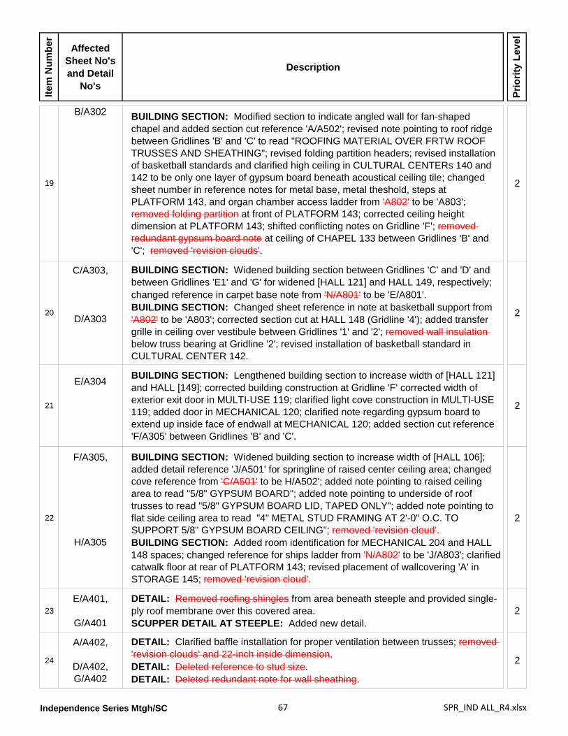
Independence Series Mtgh/SC 67 SPR_IND ALL_R4.xlsx
Item
Num
ber
Affected Sheet No's and Detail
No's
Description
Prio
rity
Leve
l
19
B/A302 BUILDING SECTION: Modified section to indicate angled wall for fan-shaped chapel and added section cut reference 'A/A502'; revised note pointing to roof ridge between Gridlines 'B' and 'C' to read "ROOFING MATERIAL OVER FRTW ROOF TRUSSES AND SHEATHING"; revised folding partition headers; revised installation of basketball standards and clarified high ceiling in CULTURAL CENTERs 140 and 142 to be only one layer of gypsum board beneath acoustical ceiling tile; changed sheet number in reference notes for metal base, metal theshold, steps at PLATFORM 143, and organ chamber access ladder from 'A802' to be 'A803'; removed folding partition at front of PLATFORM 143; corrected ceiling height dimension at PLATFORM 143; shifted conflicting notes on Gridline 'F'; removed redundant gypsum board note at ceiling of CHAPEL 133 between Gridlines 'B' and 'C'; removed 'revision clouds'.
2
20
C/A303,
D/A303
BUILDING SECTION: Widened building section between Gridlines 'C' and 'D' and between Gridlines 'E1' and 'G' for widened [HALL 121] and HALL 149, respectively; changed reference in carpet base note from 'N/A801' to be 'E/A801'.BUILDING SECTION: Changed sheet reference in note at basketball support from 'A802' to be 'A803'; corrected section cut at HALL 148 (Gridline '4'); added transfer grille in ceiling over vestibule between Gridlines '1' and '2'; removed wall insulation below truss bearing at Gridline '2'; revised installation of basketball standard in CULTURAL CENTER 142.
2
21
E/A304 BUILDING SECTION: Lengthened building section to increase width of [HALL 121] and HALL [149]; corrected building construction at Gridline 'F' corrected width of exterior exit door in MULTI-USE 119; clarified light cove construction in MULTI-USE 119; added door in MECHANICAL 120; clarified note regarding gypsum board to extend up inside face of endwall at MECHANICAL 120; added section cut reference 'F/A305' between Gridlines 'B' and 'C'.
2
22
F/A305,
H/A305
BUILDING SECTION: Widened building section to increase width of [HALL 106]; added detail reference 'J/A501' for springline of raised center ceiling area; changed cove reference from 'C/A501' to be H/A502'; added note pointing to raised ceiling area to read "5/8" GYPSUM BOARD"; added note pointing to underside of roof trusses to read "5/8" GYPSUM BOARD LID, TAPED ONLY"; added note pointing to flat side ceiling area to read "4" METAL STUD FRAMING AT 2'-0" O.C. TO SUPPORT 5/8" GYPSUM BOARD CEILING"; removed 'revision cloud'.BUILDING SECTION: Added room identification for MECHANICAL 204 and HALL 148 spaces; changed reference for ships ladder from 'N/A802' to be 'J/A803'; clarified catwalk floor at rear of PLATFORM 143; revised placement of wallcovering 'A' in STORAGE 145; removed 'revision cloud'.
2
23E/A401,
G/A401
DETAIL: Removed roofing shingles from area beneath steeple and provided single-ply roof membrane over this covered area.SCUPPER DETAIL AT STEEPLE: Added new detail.
2
24
A/A402,
D/A402,G/A402
DETAIL: Clarified baffle installation for proper ventilation between trusses; removed 'revision clouds' and 22-inch inside dimension.DETAIL: Deleted reference to stud size.DETAIL: Deleted redundant note for wall sheathing.
2
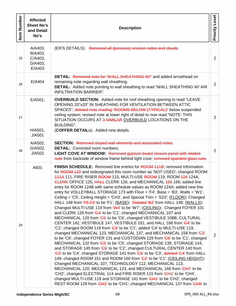
Independence Series Mtgh/SC 68 SPR_IND ALL_R4.xlsx
Item
Num
ber
Affected Sheet No's and Detail
No's
Description
Prio
rity
Leve
l
25
A/A403,B/A403,C/A403,D/A403,E/A403
(EIFS DETAILS): Removed all (previous) revision notes and clouds.
2
26E/A404
DETAIL: Removed note for "WALL SHEATHING W/" and added arrowhead on remaining note regarding wall sheathing.DETAIL: Added note pointing to wall sheathing to read "WALL SHEATHING W/ AIR INFILTRATION BARRIER".
2
27
E/A501,
H/A501,J/A501
OVERBUILD SECTION: Added note for roof sheathing opening to read "LEAVE OPENING 20"x20" IN SHEATHING FOR VENTILATION BETWEEN ATTIC SPACES"; deleted note reading "ROOMS BELOW (TYPICAL)" below suspended ceiling system; revised note at lower right of detail to now read "NOTE: THIS SITUATION OCCURS AT 3 SIMILAR OVERBUILD LOCATIONS ON THE BUILDING".(COFFER DETAILs): Added new details.
2
28
A/A502,G/A502,J/A502
SECTION: Removed sloped wall elements and associated notes.DETAIL: Corrected room numbers.LIGHT COVE AT WINDOW: Removed gypsum board closure panel with related note from backside of window frame behind light cove; removed spandrel glass note.
2
29
A601 FINISH SCHEDULE: Removed line entries for ROOM 111B; removed information for ROOM 122 and redesignated this room number as 'NOT USED'; changed ROOM 111A 111, FIRE RISER ROOM 115, MULTI-USE ROOM 119, ROOM 124 124A, CLERK OFFICE 125, HALL CLERK 126, and MECHANICAL 165 166; added line entry for ROOM 124B with same schedule values as ROOM 124A; added new line entry for VOLLEYBALL STORAGE 173 with Floor = 'F4', Base = 'B3', Walls = 'W1', Ceiling = 'C5', Ceiling Height = 'CH3', and Special Trim = 'S23'; (FLOOR): Changed HALL 148 from 'F5 F3' to be 'F1'; (BASE): Deleted 'B2' from HALL 148; (WALLS): Changed MULTI-USE 119 from 'W4' to be 'W7'; (CEILING): Changed FOYER 101 and CLERK 126 from 'C4' to be 'C1', changed MECHANICAL 107 and MECHANICAL 120 from 'C5' to be 'C6', changed VESTIBULE 108B, CULTURAL CENTER 142, VESTIBULE 147, VESTIBULE 161, and HALL 168 from 'C4' to be 'C2', changed ROOM 118 from 'C3' to be 'C1', added 'C4' to MULTI-USE 119, changed MECHANICAL 123, MECHANICAL 137, and MECHANICAL 158 from 'C2' to be 'C6', changed FOYER 131 and CUSTODIAN 129 from 'C5' to be 'C1', changed MECHANICAL 132 from 'C2' to be 'C5', changed STORAGE 139, STORAGE 144, and STORAGE 145 from 'C5' to be 'C2', changed CULTURAL CENTER 140 from 'C3' to be 'C4', changed STORAGE 141 from 'C5' to be 'C3', deleted 'C4' from HALL 149, changed ROOM 151 and ROOM 160 from 'C2' to be 'C1'; (CEILING HEIGHT): Changed MECHANICAL 107, TECHNOLOGY 112, MECHANICAL 113, MECHANICAL 120, MECHANICAL 123, and MECHANICAL 166 from 'CH7' to be 'CH2', changed ELECTRIAL 114 and FIRE RISER 115 from 'CH1' to be 'CH4', changed MULTI-USE 119 and STORAGE 141 from 'CH1' to be 'CH2', changed REST ROOM 128 from 'CH2' to be 'CH1'; changed MECHANICAL 137 from 'CH5' to
2
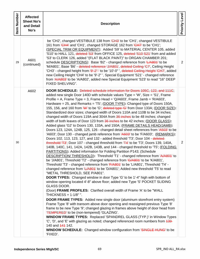
Independence Series Mtgh/SC 69 SPR_IND ALL_R4.xlsx
Item
Num
ber
Affected Sheet No's and Detail
No's
Description
Prio
rity
Leve
l
29A601
(continued)
be 'CH2', changed VESTIBULE 138 from 'CH3' to be 'CH1', changed VESTIBULE 161 from 'CH4' and 'CH1', changed STORAGE 162 from 'CH7' to be 'CH1'; (SPECIAL TRIM OR EQUIPMENT): Added 'S9' to MATERIAL CENTER 105, added 'S10' to HALL 121, deleted 'S3' from OFFICE 125, deleted 'S10 S21' from and added 'S3' to CLERK 126, added "(FLAT BLACK PAINT)" to ORGAN CHAMBER 201; schedule DESCRIPTIONS): Base 'B2' - changed reference from 'L/A801' to be 'M/A801', Base 'B6' - deleted reference 'J/A801', deleted Ceiling 'C7', Ceiling Height 'CH3' - changed height from '9'-2" ' to be '10'-0" ', deleted Ceiling Height 'CH7', added new Ceiling Height 'CH4' to be '9'-2" ', Special Equipment 'S21' - changed reference from 'A/A803' to be 'A/A802', added new Special Equipment 'S23' to read "16" DEEP FIXED SHELVING".
2
30
A602 DOOR SCHEDULE: Deleted schedule information for Doors 105C, 122, and 111C; added new single Door 140D with schedule values Type = 'W', Size = 'S1', Frame Profile = A, Frame Type = 3, Frame Head = 'Q/A603', Frame Jamb = 'R/A603', Hardware = 25, and Remarks = 'T5'; (DOOR TYPE): Changed type of Doors 150A, 155, 156, and 160 from 'W' to be 'G'; deleted type 'G' from Door 133A; (DOOR SIZE): Standardized door sizes; changed width of Doors 110A and 110B to be 34 inches; changed width of Doors 119A and 304A from 36 inches to be 48 inches; changed width of both leaves of Door 123 from 36 inches to be 42 inches; (DOOR GLASS): Added glass 'G2' to Doors 130, 133A, and 150A; (FRAME DETAILS HEAD/JAMB): Doors 123, 124A, 124B, 125, 126 - changed detail sheet references from 'A503' to be 'A603'; Door 130 - changed jamb reference from 'A603' to be 'F/A603'; (REMARKS): Doors 102, 113, 123, 127, and 132 - added threshold 'T3'; Door 104 - deleted threshold 'T3'; Door 107 - changed threshold from 'T4' to be 'T3'; Doors 139, 140A, 140B, 140C, 141, 142A, 142B, 143B, and 144 - changed threshold to 'T5'; (FOLDING PARTITIONS): Added information for Folding Partition P143; (Schedule DESCRIPTION/ THRESHOLD): Threshold 'T1' - changed reference from 'A/A801' to be 'J/A801', Threshold 'T2' - changed reference from 'G/A801' to be 'K/A801', Threshold 'T3' - changed reference from 'F/A801' to be 'L/A801', Threshold 'T4' - changed reference from 'L/A801' to be 'D/A801'; Added new threshold 'T5' to read "METAL THRESHOLD, SEE P/A801".DOOR TYPES: Changed window in door Type 'G' to be 1'-4" high with bottom of window opening located 4'-8" above floor; added new Type 'S' POCKET SLIDING GLASS DOOR.(Door) FRAME PROFILES: Clarified overall width of Frame 'A' to be "WALL THICKNESS + 1-1/8" ".
2
DOOR FRAME TYPES: Added new single door (aluminum storefront entry system) Frame Type '8' with transom above door opening and reassigned previous Type '8' frame to be new Type '9'; changed glazing in frames above height of door head from 'TEMPERED' to be (non-tempered) 'GLAZING'.WINDOW FRAME TYPES: Replaced 'SPANDREL GLASS (TYP.)' in Window Types 'C', 'D', and 'E' with glazing as noted; changed referenced room numbers from 139 140 and 141 142. WINDOW SCHEDULE: Changed window configuration from 'SINGLE HUNG' to be 'FIXED'.
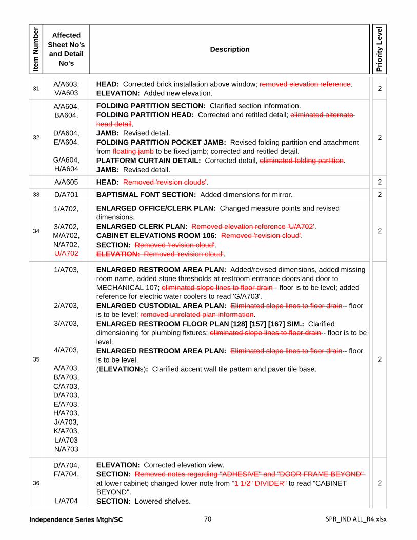
Independence Series Mtgh/SC 70 SPR_IND ALL_R4.xlsx
Item
Num
ber
Affected Sheet No's and Detail
No's
Description
Prio
rity
Leve
l
31A/A603,V/A603
HEAD: Corrected brick installation above window; removed elevation reference.ELEVATION: Added new elevation. 2
32
A/A604,BA604,
D/A604,E/A604,
G/A604,H/A604
FOLDING PARTITION SECTION: Clarified section information.FOLDING PARTITION HEAD: Corrected and retitled detail; eliminated alternate head detail.JAMB: Revised detail.FOLDING PARTITION POCKET JAMB: Revised folding partition end attachment from floating jamb to be fixed jamb; corrected and retitled detail.PLATFORM CURTAIN DETAIL: Corrected detail, eliminated folding partition.JAMB: Revised detail.
2
A/A605 HEAD: Removed 'revision clouds'. 2
33 D/A701 BAPTISMAL FONT SECTION: Added dimensions for mirror. 2
34
1/A702,
3/A702,M/A702,N/A702,U/A702
ENLARGED OFFICE/CLERK PLAN: Changed measure points and revised dimensions.ENLARGED CLERK PLAN: Removed elevation reference 'U/A702'.CABINET ELEVATIONS ROOM 106: Removed 'revision cloud'.SECTION: Removed 'revision cloud'.ELEVATION: Removed 'revision cloud'.
2
35
1/A703,
2/A703,
3/A703,
4/A703,
A/A703,B/A703,C/A703,D/A703,E/A703,H/A703,J/A703,K/A703,L/A703N/A703
ENLARGED RESTROOM AREA PLAN: Added/revised dimensions, added missing room name, added stone thresholds at restroom entrance doors and door to MECHANICAL 107; eliminated slope lines to floor drain-- floor is to be level; added reference for electric water coolers to read 'G/A703'.ENLARGED CUSTODIAL AREA PLAN: Eliminated slope lines to floor drain-- floor is to be level; removed unrelated plan information.ENLARGED RESTROOM FLOOR PLAN [128] [157] [167] SIM.: Clarified dimensioning for plumbing fixtures; eliminated slope lines to floor drain-- floor is to be level.ENLARGED RESTROOM AREA PLAN: Eliminated slope lines to floor drain-- floor is to be level.(ELEVATIONs): Clarified accent wall tile pattern and paver tile base.
2
36
D/A704,F/A704,
L/A704
ELEVATION: Corrected elevation view.SECTION: Removed notes regarding "ADHESIVE" and "DOOR FRAME BEYOND" at lower cabinet; changed lower note from "1 1/2" DIVIDER" to read "CABINET BEYOND".SECTION: Lowered shelves.
2
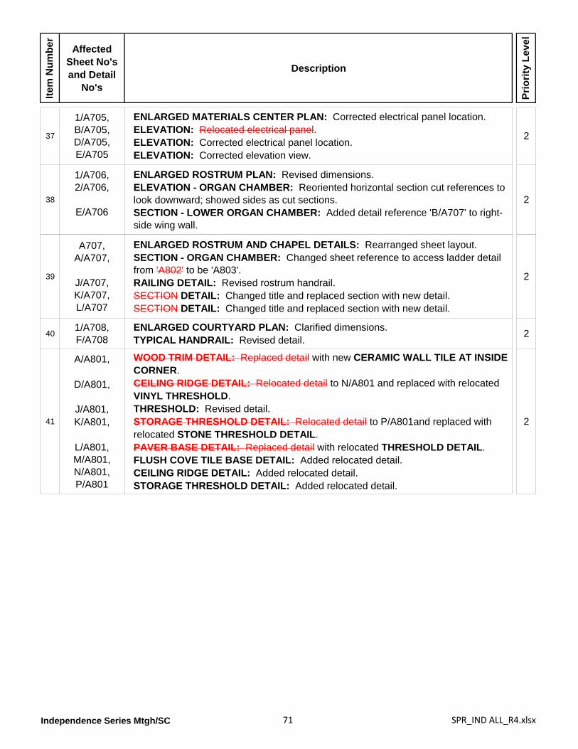
Independence Series Mtgh/SC 71 SPR_IND ALL_R4.xlsx
Item
Num
ber
Affected Sheet No's and Detail
No's
Description
Prio
rity
Leve
l
37
1/A705,B/A705,D/A705,E/A705
ENLARGED MATERIALS CENTER PLAN: Corrected electrical panel location.ELEVATION: Relocated electrical panel.ELEVATION: Corrected electrical panel location.ELEVATION: Corrected elevation view.
2
38
1/A706,2/A706,
E/A706
ENLARGED ROSTRUM PLAN: Revised dimensions.ELEVATION - ORGAN CHAMBER: Reoriented horizontal section cut references to look downward; showed sides as cut sections.SECTION - LOWER ORGAN CHAMBER: Added detail reference 'B/A707' to right-side wing wall.
2
39
A707,A/A707,
J/A707, K/A707,L/A707
ENLARGED ROSTRUM AND CHAPEL DETAILS: Rearranged sheet layout.SECTION - ORGAN CHAMBER: Changed sheet reference to access ladder detail from 'A802' to be 'A803'.RAILING DETAIL: Revised rostrum handrail.SECTION DETAIL: Changed title and replaced section with new detail.SECTION DETAIL: Changed title and replaced section with new detail.
2
401/A708,F/A708
ENLARGED COURTYARD PLAN: Clarified dimensions.TYPICAL HANDRAIL: Revised detail. 2
41
A/A801,
D/A801,
J/A801,K/A801,
L/A801,M/A801,N/A801,P/A801
WOOD TRIM DETAIL: Replaced detail with new CERAMIC WALL TILE AT INSIDE CORNER.CEILING RIDGE DETAIL: Relocated detail to N/A801 and replaced with relocated VINYL THRESHOLD.THRESHOLD: Revised detail.STORAGE THRESHOLD DETAIL: Relocated detail to P/A801and replaced with relocated STONE THRESHOLD DETAIL.PAVER BASE DETAIL: Replaced detail with relocated THRESHOLD DETAIL.FLUSH COVE TILE BASE DETAIL: Added relocated detail.CEILING RIDGE DETAIL: Added relocated detail.STORAGE THRESHOLD DETAIL: Added relocated detail.
2
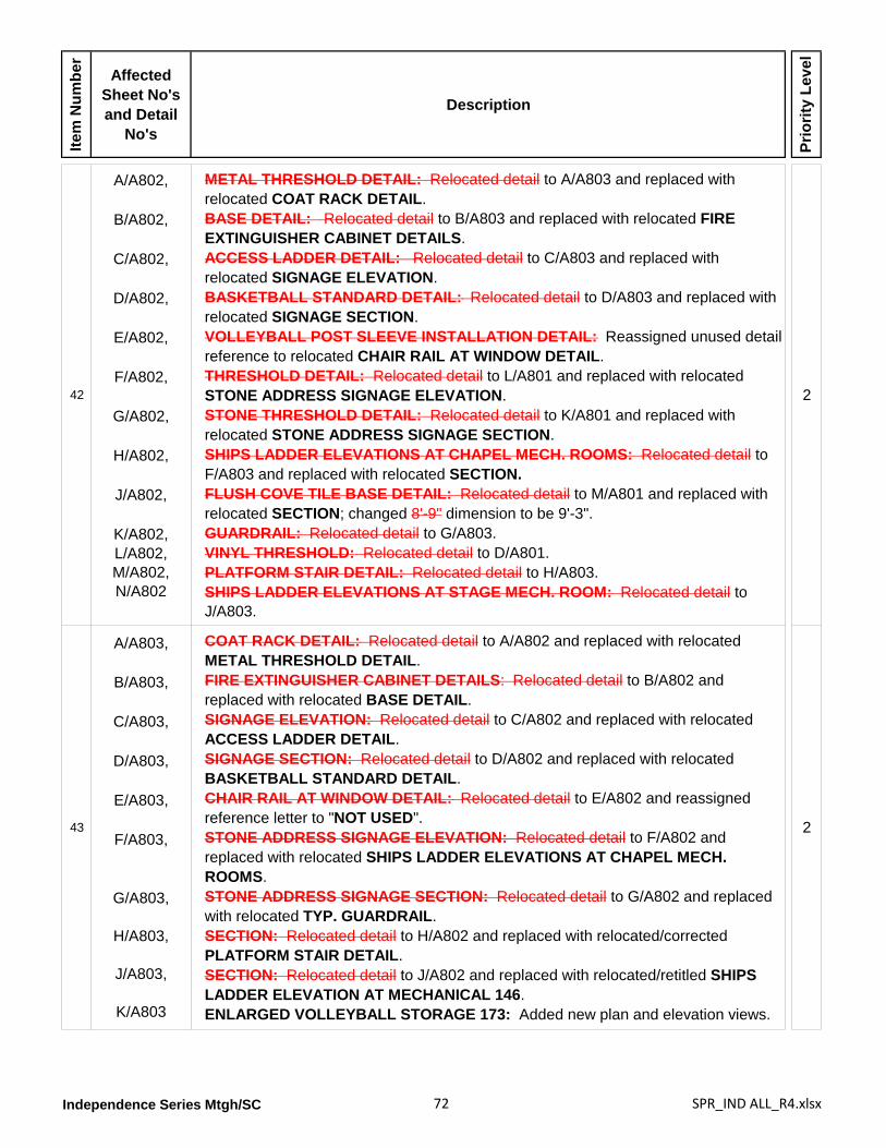
Independence Series Mtgh/SC 72 SPR_IND ALL_R4.xlsx
Item
Num
ber
Affected Sheet No's and Detail
No's
Description
Prio
rity
Leve
l
42
A/A802,
B/A802,
C/A802,
D/A802,
E/A802,
F/A802,
G/A802,
H/A802,
J/A802,
K/A802,L/A802,M/A802,N/A802
METAL THRESHOLD DETAIL: Relocated detail to A/A803 and replaced with relocated COAT RACK DETAIL.BASE DETAIL: Relocated detail to B/A803 and replaced with relocated FIRE EXTINGUISHER CABINET DETAILS.ACCESS LADDER DETAIL: Relocated detail to C/A803 and replaced with relocated SIGNAGE ELEVATION.BASKETBALL STANDARD DETAIL: Relocated detail to D/A803 and replaced with relocated SIGNAGE SECTION.VOLLEYBALL POST SLEEVE INSTALLATION DETAIL: Reassigned unused detail reference to relocated CHAIR RAIL AT WINDOW DETAIL.THRESHOLD DETAIL: Relocated detail to L/A801 and replaced with relocated STONE ADDRESS SIGNAGE ELEVATION.STONE THRESHOLD DETAIL: Relocated detail to K/A801 and replaced with relocated STONE ADDRESS SIGNAGE SECTION.SHIPS LADDER ELEVATIONS AT CHAPEL MECH. ROOMS: Relocated detail to F/A803 and replaced with relocated SECTION.FLUSH COVE TILE BASE DETAIL: Relocated detail to M/A801 and replaced with relocated SECTION; changed 8'-9" dimension to be 9'-3".GUARDRAIL: Relocated detail to G/A803.VINYL THRESHOLD: Relocated detail to D/A801.PLATFORM STAIR DETAIL: Relocated detail to H/A803.SHIPS LADDER ELEVATIONS AT STAGE MECH. ROOM: Relocated detail to J/A803.
2
43
A/A803,
B/A803,
C/A803,
D/A803,
E/A803,
F/A803,
G/A803,
H/A803,
J/A803,
K/A803
COAT RACK DETAIL: Relocated detail to A/A802 and replaced with relocated METAL THRESHOLD DETAIL.FIRE EXTINGUISHER CABINET DETAILS: Relocated detail to B/A802 and replaced with relocated BASE DETAIL.SIGNAGE ELEVATION: Relocated detail to C/A802 and replaced with relocated ACCESS LADDER DETAIL.SIGNAGE SECTION: Relocated detail to D/A802 and replaced with relocated BASKETBALL STANDARD DETAIL.CHAIR RAIL AT WINDOW DETAIL: Relocated detail to E/A802 and reassigned reference letter to "NOT USED".STONE ADDRESS SIGNAGE ELEVATION: Relocated detail to F/A802 and replaced with relocated SHIPS LADDER ELEVATIONS AT CHAPEL MECH. ROOMS.STONE ADDRESS SIGNAGE SECTION: Relocated detail to G/A802 and replaced with relocated TYP. GUARDRAIL.SECTION: Relocated detail to H/A802 and replaced with relocated/corrected PLATFORM STAIR DETAIL.SECTION: Relocated detail to J/A802 and replaced with relocated/retitled SHIPS LADDER ELEVATION AT MECHANICAL 146.ENLARGED VOLLEYBALL STORAGE 173: Added new plan and elevation views.
2
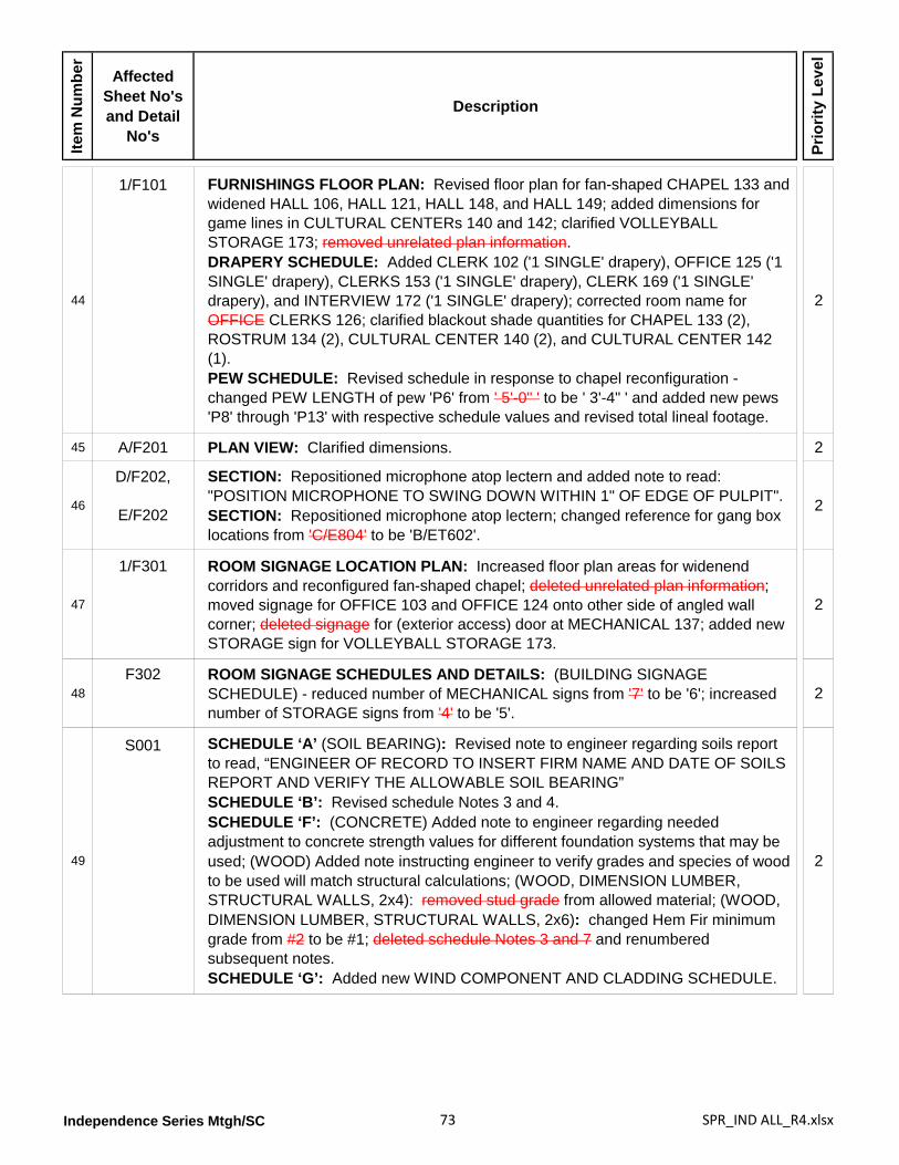
Independence Series Mtgh/SC 73 SPR_IND ALL_R4.xlsx
Item
Num
ber
Affected Sheet No's and Detail
No's
Description
Prio
rity
Leve
l
44
1/F101 FURNISHINGS FLOOR PLAN: Revised floor plan for fan-shaped CHAPEL 133 and widened HALL 106, HALL 121, HALL 148, and HALL 149; added dimensions for game lines in CULTURAL CENTERs 140 and 142; clarified VOLLEYBALL STORAGE 173; removed unrelated plan information.DRAPERY SCHEDULE: Added CLERK 102 ('1 SINGLE' drapery), OFFICE 125 ('1 SINGLE' drapery), CLERKS 153 ('1 SINGLE' drapery), CLERK 169 ('1 SINGLE' drapery), and INTERVIEW 172 ('1 SINGLE' drapery); corrected room name for OFFICE CLERKS 126; clarified blackout shade quantities for CHAPEL 133 (2), ROSTRUM 134 (2), CULTURAL CENTER 140 (2), and CULTURAL CENTER 142 (1).PEW SCHEDULE: Revised schedule in response to chapel reconfiguration - changed PEW LENGTH of pew 'P6' from ' 5'-0" ' to be ' 3'-4" ' and added new pews 'P8' through 'P13' with respective schedule values and revised total lineal footage.
2
45 A/F201 PLAN VIEW: Clarified dimensions. 2
46
D/F202,
E/F202
SECTION: Repositioned microphone atop lectern and added note to read: "POSITION MICROPHONE TO SWING DOWN WITHIN 1" OF EDGE OF PULPIT".SECTION: Repositioned microphone atop lectern; changed reference for gang box locations from 'C/E804' to be 'B/ET602'.
2
47
1/F301 ROOM SIGNAGE LOCATION PLAN: Increased floor plan areas for widenend corridors and reconfigured fan-shaped chapel; deleted unrelated plan information; moved signage for OFFICE 103 and OFFICE 124 onto other side of angled wall corner; deleted signage for (exterior access) door at MECHANICAL 137; added new STORAGE sign for VOLLEYBALL STORAGE 173.
2
48F302 ROOM SIGNAGE SCHEDULES AND DETAILS: (BUILDING SIGNAGE
SCHEDULE) - reduced number of MECHANICAL signs from '7' to be '6'; increased number of STORAGE signs from '4' to be '5'.
2
49
S001 SCHEDULE ‘A’ (SOIL BEARING): Revised note to engineer regarding soils report to read, “ENGINEER OF RECORD TO INSERT FIRM NAME AND DATE OF SOILS REPORT AND VERIFY THE ALLOWABLE SOIL BEARING”SCHEDULE ‘B’: Revised schedule Notes 3 and 4.SCHEDULE ‘F’: (CONCRETE) Added note to engineer regarding needed adjustment to concrete strength values for different foundation systems that may be used; (WOOD) Added note instructing engineer to verify grades and species of wood to be used will match structural calculations; (WOOD, DIMENSION LUMBER, STRUCTURAL WALLS, 2x4): removed stud grade from allowed material; (WOOD, DIMENSION LUMBER, STRUCTURAL WALLS, 2x6): changed Hem Fir minimum grade from #2 to be #1; deleted schedule Notes 3 and 7 and renumbered subsequent notes.SCHEDULE ‘G’: Added new WIND COMPONENT AND CLADDING SCHEDULE.
2
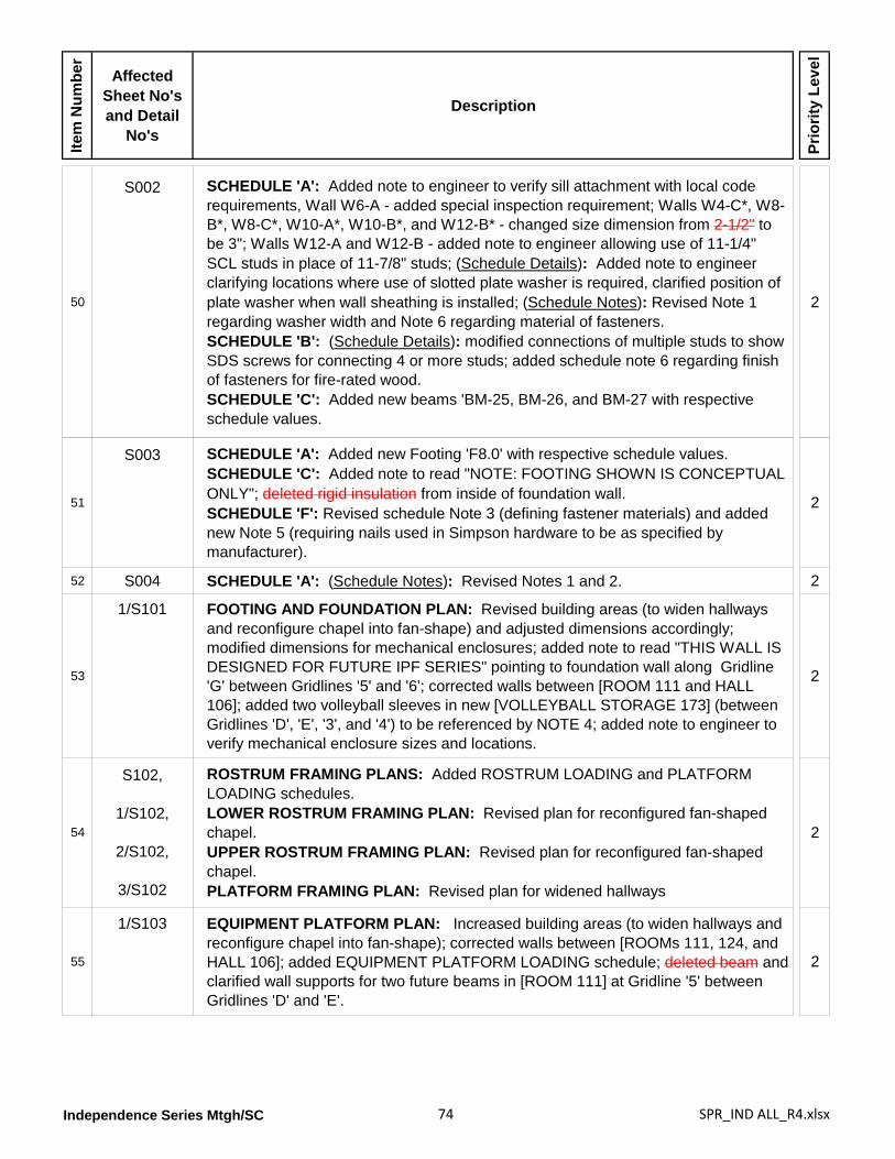
Independence Series Mtgh/SC 74 SPR_IND ALL_R4.xlsx
Item
Num
ber
Affected Sheet No's and Detail
No's
Description
Prio
rity
Leve
l
50
S002 SCHEDULE 'A': Added note to engineer to verify sill attachment with local code requirements, Wall W6-A - added special inspection requirement; Walls W4-C*, W8-B*, W8-C*, W10-A*, W10-B*, and W12-B* - changed size dimension from 2-1/2" to be 3"; Walls W12-A and W12-B - added note to engineer allowing use of 11-1/4" SCL studs in place of 11-7/8" studs; (Schedule Details): Added note to engineer clarifying locations where use of slotted plate washer is required, clarified position of plate washer when wall sheathing is installed; (Schedule Notes): Revised Note 1 regarding washer width and Note 6 regarding material of fasteners.SCHEDULE 'B': (Schedule Details): modified connections of multiple studs to show SDS screws for connecting 4 or more studs; added schedule note 6 regarding finish of fasteners for fire-rated wood.SCHEDULE 'C': Added new beams 'BM-25, BM-26, and BM-27 with respective schedule values.
2
51
S003 SCHEDULE 'A': Added new Footing 'F8.0' with respective schedule values.SCHEDULE 'C': Added note to read "NOTE: FOOTING SHOWN IS CONCEPTUAL ONLY"; deleted rigid insulation from inside of foundation wall.SCHEDULE 'F': Revised schedule Note 3 (defining fastener materials) and added new Note 5 (requiring nails used in Simpson hardware to be as specified by manufacturer).
2
52 S004 SCHEDULE 'A': (Schedule Notes): Revised Notes 1 and 2. 2
53
1/S101 FOOTING AND FOUNDATION PLAN: Revised building areas (to widen hallways and reconfigure chapel into fan-shape) and adjusted dimensions accordingly; modified dimensions for mechanical enclosures; added note to read "THIS WALL IS DESIGNED FOR FUTURE IPF SERIES" pointing to foundation wall along Gridline 'G' between Gridlines '5' and '6'; corrected walls between [ROOM 111 and HALL 106]; added two volleyball sleeves in new [VOLLEYBALL STORAGE 173] (between Gridlines 'D', 'E', '3', and '4') to be referenced by NOTE 4; added note to engineer to verify mechanical enclosure sizes and locations.
2
54
S102,
1/S102,
2/S102,
3/S102
ROSTRUM FRAMING PLANS: Added ROSTRUM LOADING and PLATFORM LOADING schedules.LOWER ROSTRUM FRAMING PLAN: Revised plan for reconfigured fan-shaped chapel.UPPER ROSTRUM FRAMING PLAN: Revised plan for reconfigured fan-shaped chapel.PLATFORM FRAMING PLAN: Revised plan for widened hallways
2
55
1/S103 EQUIPMENT PLATFORM PLAN: Increased building areas (to widen hallways and reconfigure chapel into fan-shape); corrected walls between [ROOMs 111, 124, and HALL 106]; added EQUIPMENT PLATFORM LOADING schedule; deleted beam and clarified wall supports for two future beams in [ROOM 111] at Gridline '5' between Gridlines 'D' and 'E'.
2
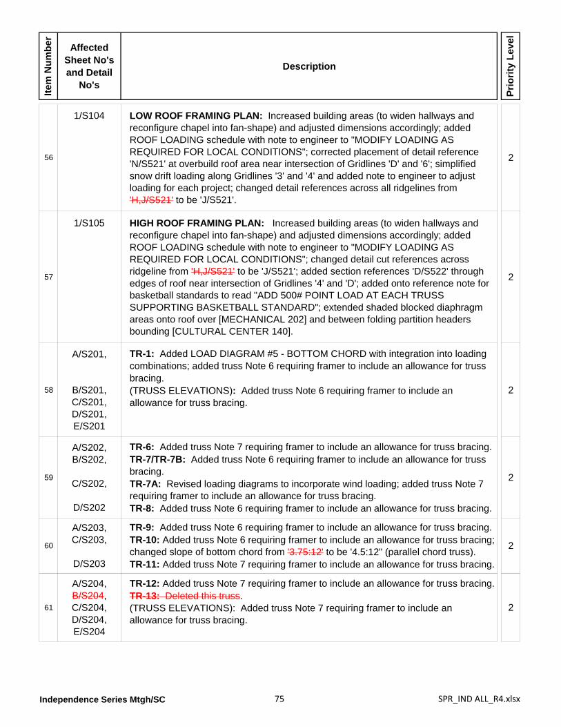
Independence Series Mtgh/SC 75 SPR_IND ALL_R4.xlsx
Item
Num
ber
Affected Sheet No's and Detail
No's
Description
Prio
rity
Leve
l
56
1/S104 LOW ROOF FRAMING PLAN: Increased building areas (to widen hallways and reconfigure chapel into fan-shape) and adjusted dimensions accordingly; added ROOF LOADING schedule with note to engineer to "MODIFY LOADING AS REQUIRED FOR LOCAL CONDITIONS"; corrected placement of detail reference 'N/S521' at overbuild roof area near intersection of Gridlines 'D' and '6'; simplified snow drift loading along Gridlines '3' and '4' and added note to engineer to adjust loading for each project; changed detail references across all ridgelines from 'H,J/S521' to be 'J/S521'.
2
57
1/S105 HIGH ROOF FRAMING PLAN: Increased building areas (to widen hallways and reconfigure chapel into fan-shape) and adjusted dimensions accordingly; added ROOF LOADING schedule with note to engineer to "MODIFY LOADING AS REQUIRED FOR LOCAL CONDITIONS"; changed detail cut references across ridgeline from 'H,J/S521' to be 'J/S521'; added section references 'D/S522' through edges of roof near intersection of Gridlines '4' and 'D'; added onto reference note for basketball standards to read "ADD 500# POINT LOAD AT EACH TRUSS SUPPORTING BASKETBALL STANDARD"; extended shaded blocked diaphragm areas onto roof over [MECHANICAL 202] and between folding partition headers bounding [CULTURAL CENTER 140].
2
58
A/S201,
B/S201,C/S201,D/S201,E/S201
TR-1: Added LOAD DIAGRAM #5 - BOTTOM CHORD with integration into loading combinations; added truss Note 6 requiring framer to include an allowance for truss bracing.(TRUSS ELEVATIONS): Added truss Note 6 requiring framer to include an allowance for truss bracing.
2
59
A/S202,B/S202,
C/S202,
D/S202
TR-6: Added truss Note 7 requiring framer to include an allowance for truss bracing.TR-7/TR-7B: Added truss Note 6 requiring framer to include an allowance for truss bracing.TR-7A: Revised loading diagrams to incorporate wind loading; added truss Note 7 requiring framer to include an allowance for truss bracing.TR-8: Added truss Note 6 requiring framer to include an allowance for truss bracing.
2
60
A/S203,C/S203,
D/S203
TR-9: Added truss Note 6 requiring framer to include an allowance for truss bracing.TR-10: Added truss Note 6 requiring framer to include an allowance for truss bracing; changed slope of bottom chord from '3.75:12' to be '4.5:12" (parallel chord truss).TR-11: Added truss Note 7 requiring framer to include an allowance for truss bracing.
2
61
A/S204,B/S204,C/S204,D/S204,E/S204
TR-12: Added truss Note 7 requiring framer to include an allowance for truss bracing.TR-13: Deleted this truss.(TRUSS ELEVATIONS): Added truss Note 7 requiring framer to include an allowance for truss bracing.
2
Independence Series Mtgh/SC 76 SPR_IND ALL_R4.xlsx
Item
Num
ber
Affected Sheet No's and Detail
No's
Description
Prio
rity
Leve
l
62
A/S401,B/S401,C/S401,F/S401,H/S401
ROOF FRAMING LAYOUT AT STEEPLE: Deleted Note 4. CONNECTION AT TRUSS: Revised 'bucket' configuration.BASE PLATE CONNECTION AT WOOD BEAM: Revised 'bucket' configuration.DETAIL AT STEEPLE: Revised 'bucket' configuration.WOOD BEAM CONNECTION TO GIRDER TRUSS: Revised 'bucket' configuration.
2
63A/S511 FOLDING DOOR BEAM: Revised note referencing wood beam back to schedule
information. 2
64 S/S512 PLATFORM RAMP: Changed reference to footing from 'M/S501' to be 'L/S501'. 2
65
L/S522 FOLDING PARTITION SECTION (BETWEEN CHAPEL AND CULTURAL HALL): Corrected section view; changed bolting at SECTION A-A and SECTION B-B to eliminate counterbored configuration at bottom sides of sheathing-- bolts heads are below.
2
66
FS101,
1/FS101
(GENERAL NOTES): Appended Note 6 to read "6.3 LIGHT HAZARD FOR THE REMAINDER OF THE BUILDING."; added Note 17 to read "THIS BUILDING IS DESIGNED TO BE EXPANDED IN PHASES WITHOUT MAJOR MODIFICATION TO THE ALREADY INSTALLED SPRINKLER SYSTEM., 17.1 THE SPRINKLER LINES ARE TO BE THE SAME DIAMETER FROM THE END HEAD TO THE RISER NIPPLE OR CROSS MAIN., 17.2 THE SPRINKLER MAINS ARE TO BE THE SAME DIAMETER FROM THE TOP OF THE SYSTEM RISER TO THE END OF THE MAIN."MAIN FLOOR PLAN: Revised sprinkler head layout to match changes to reflected ceiling plan resulting from widened hallways and fan-shaped chapel reconfiguration.
2
67
A/FS201,B/FS201,D/FS201,
3/FS201,
4/FS201
(SECTIONs): Revised piping to place sprinkler heads at 8'-8" above finished floor; modified sections for widened hallwaysSECTION: Re-routed sprinkler piping with added swing joints in MECHANICAL 202 and 203 to improve headroom.MECH ACCESS PLAN: Revised floor plan in accordance with fan-shaped chapel reconfiguration; added note to read "RUN PIPING AT 6" BELOW CEILING FOR HEADROOM".MECH ACCESS PLAN: Added sprinkler piping over walkway connecting both areas of MECHANICAL 204
2
68
P101 MAIN FLOOR PLUMBING PLAN: Revised floor plan areas to widen hallways and reconfigure chapel to fan shape; added note pointing to water heater (WH-1) in [MECHANICAL] 113 to read "FLUE AND INTAKE PIPING. OFFSET- SEE M102 FOR LOCATION"; revised note near intersection of Gridlines 'C' and '6' to read "RISE UP INTO CEILING SPACE. DO NOT RISE ABOVE BOTTOM OF WALL TOP PLATE"; re-routed gas line to run over [PLATFORM] 143 and upsized gas line to be 2 inches at rise in wall near Gridline '3'; re-routed water supply piping to [SACRAMENT PREPARATION] 135 and added note near door to [CULTURAL CENTER] 140 to read "RISE UP INTO CHAPEL CEILING SPACE. DO NOT RISE ABOVE BOTTOM OF WALL TOP PLATE"; removed under-sink water heater 'WH-3' in [RESTROOM] 167 and added new water heater 'WH-2' in [MECHANICAL] 166.
2
Independence Series Mtgh/SC 77 SPR_IND ALL_R4.xlsx
Item
Num
ber
Affected Sheet No's and Detail
No's
Description
Prio
rity
Leve
l
69
P102 EQUIPMENT PLATFORM PLUMBING PLAN: Revised floor plan areas for reconfigured fan-shaped chapel; rerouted gas line from below to equipment platform areas between Gridlines 'E' and 'F' with increased size from '1-1/4" ' to be '2" '; added vent pipe from below near intersection of Gridlines 'F' and '3' with note to read "1 1/2" VENT FROM BELOW SEE P101 FOR CONTINUATION".
2
70
P401,
1/P401,
3/P401,
4/P401
PLUMBING FIXTURE SCHEDULE: Changed hot and cold water pipe sizes for water heater 'WH-1' from 3/4 inch to be 1-inch; removed schedule information for water heater 'WH-3'; removed reference to future needs in schedule Note 1.MAIN RESTROOMS AND FONT WASTE AND VENT: Revised vent piping (and some sewer piping) for floor drains (FD-1) in [MEN] 108A, [WOMEN] 109, [MECHANICAL] 113, [REST ROOM] 128, and [CUSTODIAL] 129; added note pointing to end of sewer piping to read "SEE SHEET P101 FOR CONTINUATION".MENS RESTROOM AND SERVING AREA WASTE AND VENT: Revised venting in [MENS] 152; added notes pointing to ends of sewer piping to read "SEE SHEET P101 FOR CONTINUATION".MENS RESTROOM AND SERVING AREA WATER SUPPLY: Added notes pointing to ends of water piping to read "SEE SHEET P101 FOR CONTINUATION".
2
71
2/P402,
4/P402
RESTROOMS 108 AND 109 WASTE AND VENT: Revised venting for floor drains 'FD-1' in [MEN 108A], [WOMEN 109], [MECHANICAL 113], and [CUSTODIAL] 129.MEN'S RESTROOM 152 WASTE AND VENT: Revised venting for floor drain 'FD-1' in [MENS 152].
2
72
A/P501,D/P501,
G/P501,
J/P501
SEISMIC VALVE DETAIL: Added designer note to edit valve size.WALL CLEANOUT DETAIL: Eliminated gap between gypsum board wall and cleanout fitting.GAS LINE CONNECTION DETAIL: Deleted ground joint union— flexible connector will serve as union.COOLING COIL CONDENSATE DRAIN DETAIL: Added note describing acceptable manufactured unit (EZTRAP).
2
73A/P502 GAS PIPING SCHEME: Added note stating International Fuel Gas Code (IFGC)
used for gas pipe sizing; added note stating BTU/HR capacities are maximum allowed by specified equipment manufacturers; deleted 1 1/2" capped line for future connection near fan units 'F2' and 'F5'.
2
Independence Series Mtgh/SC 78 SPR_IND ALL_R4.xlsx
Item
Num
ber
Affected Sheet No's and Detail
No's
Description
Prio
rity
Leve
l
74
M101 MAIN FLOOR MECHANICAL PLAN: Revised floor plan for widened hallways and reconfigured fan-shaped chapel; removed unrelated plan information; [WOMEN] 109 - repositioned exhaust fan 'EF-4''; [TECHNOLOGY] 112 - added new exhaust fan 'EF-11' to discharge into ceiling space; [ROOM] 124[B] - changed supply air duct size from 10-inch diameter to be 8-inch diameter; [OFFICE] 125 - changed supply air duct size from 12-inch to be 10-inch diameter; [CLERK] 126 - changed supply air duct size from 10-inch to be 8-inch diameter; [CUSTODIAL] 129 - changed air supply from sidewall diffuser 'S-1' to be ceiling diffuser 'D-1'; changed exhaust fan 'EF-7' installation from wall to ceiling; [MECHANICAL] 132 - changed size of return air duct risers from '16x20' to be '16x22' and clarified that return air plenum is divided; [CHAPEL] 133 - changed volume of all supply air diffusers 'D-6' from '800' to be '700'; [MECHANICAL] 138 - changed size of return air riser duct from '30x14' to be '16x22'; [CULTURAL CENTER] 140 - changed all volumes for supply air diffusers 'S-3' from '800' to be '700 cfm', changed size of supply air duct riser (nearest folding partition centerline) from '16x12' to be '18x12' and changed adjacent duct size from '16x10' to be '22x10'; [CULTURAL CENTER] 142 - changed volume for supply air diffusers 'S-3' from '800' to be '700 cfm'; [PLATFORM] 143 - changed sidewall return air register (in wall shared with STORAGE 144) from 'R-9' to be 'R-7'; [HALL] 148 - changed volume for supply air diffuser 'D-3' (near VESTIBULE 147) from '285' to be '235'; [HALL] 149 - changed volume for supply air diffuser 'D-2' from '120' to be '100'; [SERVING AREA] 150 - changed volume for supply air diffuser 'D-3' from '300' to be '245'; [ROOM] 151 - changed volume for supply air diffuser 'D-2' from '240' to be '195'; [MEN] 152 - changed volume for supply air diffuser 'D-1' from '100' to be '80'; [CLERK] 153 - changed volume for supply air diffuser 'D-2' from '180' to be '150'; [OFFICE] 154 - changed volume for supply air diffuser 'D-3' from '325' to be '265'; [ROOMs] 155 and 156 - changed volume for supply air diffuser 'D-2' from '200' to be '165'; (GENERAL NOTES): Added text to Note 1 to read "COORDINATE DUCT RISERS IN STUD WALLS WITH ELECTRICAL CONTRACTOR"; changed text in Note 6 from "M301"
2
to be "M300 SHEETS"; modified Note 7 to clarify placement of sheet metal bottom to be " 8" FROM ABOVE FINISH CEILING..."
75
M102 EQUIPMENT PLATFORM MECHANICAL PLAN: Revised floor plan for widened hallways and reconfigured fan-shaped chapel; added (offset) flue for water heater (between Gridlines 'D', 'E', '5', and '6') with note to coordinate with plumbing information on sheet P101; added offsets for flue and intake piping (five locations between Gridlines '5' and '6') to clear ridge vent; [MECHANICAL] 202 - revised return air ductwork connecting fan units with duct drops in response to reconfigured fan-shaped chapel and resized plenum at louver 'L-5' from '22x12x16' to be '22x4x16'; [MECHANICAL] 203 - revised return air ductwork connecting fan units with duct drops in response to reconfigured fan shaped chapel, revised exhaust air/outside air ductwork connected to energy recovery ventilators and (switched) louvers 'L-7' and 'L-8'; changed louver plenum boxes along Gridline '2' from '10x16' to be '4x16'; [MECHANICAL] 204 - changed louver plenum boxes along Gridlines '2' and '3' from '10x16' to be '4x16'; deleted section cut reference 'E/M302' near Gridline '3' between Gridlines 'F' and 'G', reoriented remaining section cut reference 'E/M302', and added new flue for fan unit 'F13' with note to read "FAN UNIT FLUE AND INTAKE PIPING".
2
Independence Series Mtgh/SC 79 SPR_IND ALL_R4.xlsx
Item
Num
ber
Affected Sheet No's and Detail
No's
Description
Prio
rity
Leve
l
76
A/M301,
G/M301,
H/M301,
J/M301
SECTION: Revised notes pointing to ceiling supply air diffusers 'D-3' in ROOM 104 and 'D-4' in ROOM 111 to read "SA DIFFUSER - SEE PLANS FOR CFM AND SIZE".SECTION: Revised notes pointing to ceiling supply air diffusers 'D-3' in ROOM 116 , 'D-3' in ROOM 117, 'D-5' in ROOM 118, and 'D-1' in RESTROOM 128 to read "SA DIFFUSER(S) - SEE PLANS FOR CFM AND SIZE".SECTION: Revised notes pointing to ceiling supply air diffusers 'D-6' in CHAPEL 133 to delete supply volumes '800' and read "SEE PLANS FOR CFMs"; added room names and numbers for upper mechanical spaces.SECTION: Revised notes pointing to sidewall supply air diffusers 'S-3' in CULTURAL CENTER 140 to delete supply volumes '800' and read "SEE PLANS FOR CFMs", added ductwork connected to energy recovery ventilator (ERV-8a) near Gridline '2'; added room names and numbers for upper mechanical spaces.
2
77
A/M302,
B/M302,
C/M302,
D/M302,
E/M302,
F/M302
SECTION: Modified return air ductwork routing for fan units 'F-7c' and 'F-7d'; revised ductwork connected to fan unit 'F-6' from '16x10 RA' and '16x10 SA' to be '22x10 RA' and '22x10 SA' respectively.SECTION: Corrected section view to right of Gridline 'C'; revised exhaust air/outside air ductwork connected to energy recovery ventilator 'ERV-8a' and fan units 'F-7a' and 'F-7b' and (switched) louvers 'L-7' and 'L-8'; changed plenum boxes for louvers 'L-7' (and 'L-8') from '10x16' to be '4x16'; changed return air duct drop near Gridline 'C' from '30x14' to be '16x22'.SECTION: Revised notes pointing to both ceiling supply air diffusers in [PLATFORM 143 beyond] (D-5) to read "SA DIFFUSER BEYOND RAMP WALL - SEE PLANS FOR CFM AND SIZE"; changed plenum box for louver 'L-7' at Gridline '2' from '10x16' to be '4x16'.SECTION: Changed plenum box size for louver 'L-8' (near Gridline 'E') from '10x16' to be '4x16'.SECTION: Revised notes pointing to ceiling supply air diffusers [in SERVING AREA 150, HALL 149, and CLERK 153] from CFM information for 'D-2' and 'D-3' to read "SA DIFFUSER - SEE PLANS FOR CFM AND SIZE".SECTION: Added new section.
2
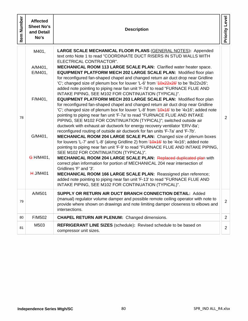
Independence Series Mtgh/SC 80 SPR_IND ALL_R4.xlsx
Item
Num
ber
Affected Sheet No's and Detail
No's
Description
Prio
rity
Leve
l
78
M401,
A/M401,E/M401,
F/M401,
G/M401,
G H/M401,
H J/M401
LARGE SCALE MECHANICAL FLOOR PLANS (GENERAL NOTES): Appended text onto Note 1 to read "COORDINATE DUCT RISERS IN STUD WALLS WITH ELECTRICAL CONTRACTOR".MECHANICAL ROOM 113 LARGE SCALE PLAN: Clarified water heater space.EQUIPMENT PLATFORM MECH 202 LARGE SCALE PLAN: Modified floor plan for reconfigured fan-shaped chapel and changed return air duct drop near Gridline 'C'; changed size of plenum box for louver 'L-6' from '10x22x26' to be '8x22x26'; added note pointing to piping near fan unit 'F-7d' to read "FURNACE FLUE AND INTAKE PIPING, SEE M102 FOR CONTINUATION (TYPICAL)".EQUIPMENT PLATFORM MECH 203 LARGE SCALE PLAN: Modified floor plan for reconfigured fan-shaped chapel and changed return air duct drop near Gridline 'C'; changed size of plenum box for louver 'L-8' from '10x16' to be '4x16'; added note pointing to piping near fan unit 'F-7a' to read "FURNACE FLUE AND INTAKE PIPING, SEE M102 FOR CONTINUATION (TYPICAL)"; switched outside air ductwork with exhaust air ductwork for energy recovery ventilator 'ERV-8a'; reconfigured routing of outside air ductwork for fan units 'F-7a' and 'F-7b'.MECHANICAL ROOM 204 LARGE SCALE PLAN: Changed size of plenum boxes for louvers 'L-7' and 'L-8' (along Gridline 2) from '10x16' to be '4x16'; added note pointing to piping near fan unit 'F-9' to read "FURNACE FLUE AND INTAKE PIPING, SEE M102 FOR CONTINUATION (TYPICAL)".MECHANICAL ROOM 204 LARGE SCALE PLAN: Replaced duplicated plan with correct plan information for portion of MECHANICAL 204 near intersection of Gridlines 'F' and '3'.MECHANICAL ROOM 166 LARGE SCALE PLAN: Reassigned plan reference; added note pointing to piping near fan unit 'F-13' to read "FURNACE FLUE AND INTAKE PIPING, SEE M102 FOR CONTINUATION (TYPICAL)".
2
79
A/M501 SUPPLY OR RETURN AIR DUCT BRANCH CONNECTION DETAIL: Added (manual) regulator volume damper and possible remote ceiling operator with note to provide where shown on drawings and note limiting damper closeness to elbows and intersections.
2
80 F/M502 CHAPEL RETURN AIR PLENUM: Changed dimensions. 2
81M503 REFRIGERANT LINE SIZES (schedule): Revised schedule to be based on
compressor unit sizes. 2
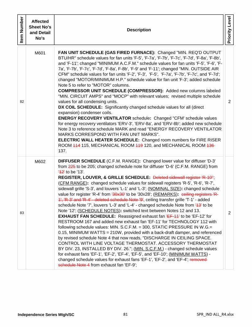
Independence Series Mtgh/SC 81 SPR_IND ALL_R4.xlsx
Item
Num
ber
Affected Sheet No's and Detail
No's
Description
Prio
rity
Leve
l
82
M601 FAN UNIT SCHEDULE (GAS FIRED FURNACE): Changed "MIN. REQ'D OUTPUT BTU/HR" schedule values for fan units 'F-5', 'F-7a', 'F-7b', 'F-7c', 'F-7d', 'F-8a', 'F-8b', and 'F-11'; changed "MINIMUM A.C.F.M." schedule values for fan units 'F-5', 'F-6', 'F-7a', 'F-7b', 'F-7c', 'F-7d', 'F-8a', F-8b', 'F-9' and 'F-11'; changed "MIN. OUTSIDE AIR CFM" schedule values for fan units 'F-2', 'F-3', 'F-5', 'F-7a', 'F-7b', 'F-7c', and 'F-7d'; changed "MOTOR/MINIMUM H.P." schedule value for fan unit 'F-3'; added schedule Note 5 to refer to "MOTOR" columns.COMPRESSOR UNIT SCHEDULE (COMPRESSOR): Added new columns labeled "MIN. CIRCUIT AMPS" and "MOCP" with relevant values; revised multiple schedule values for all condensing units.DX COIL SCHEDULE: Significantly changed schedule values for all (direct expansion) condenser coils.ENERGY RECOVERY VENTILATOR schedule: Changed "CFM' schedule values for energy recovery ventilators 'ERV-3', 'ERV-8a', and 'ERV-8b'; added new schedule Note 3 to reference schedule MARK and read "ENERGY RECOVERY VENTILATOR MARKS CORRESPOND WITH FAN UNIT MARKS".ELECTRIC WALL HEATER SCHEDULE: Changed room numbers for FIRE RISER ROOM 114 115, MECHANICAL ROOM 119 120, and MECHANICAL ROOM 136 137.
2
83
M602 DIFFUSER SCHEDULE (C.F.M. RANGE): Changed lower value for diffuser 'D-3' from 225 to be 205; changed schedule note for diffuser 'D-6' (C.F.M. RANGE) from '12' to be '13'.REGISTER, LOUVER, & GRILLE SCHEDULE: Deleted sidewall register 'R-10''; (CFM RANGE): changed schedule values for sidewall registers 'R-5', 'R-6', 'R-7', sidewall grille 'S-3', and louvers 'L-1' and 'L-3'; (NOMINAL SIZE): changed schedule value for register 'R-4' from '30x30' to be '30x28'; (REMARKS): ceiling registers 'R-1', 'R-3' and 'R-4' - deleted schedule Note '9', ceiling transfer grille 'T-1' - added schedule Note '7', louvers 'L-3' and 'L-4' - changed schedule Note from '13' to be Note '12'; (SCHEDULE NOTES): switched text between Notes 12 and 13.EXHAUST FAN SCHEDULE: Reassigned exhaust fan 'EF-11' to be 'EF-12' for RESTROOM 167 and added new exhaust fan 'EF-11' for TECHNOLOGY 112 with following schedule values: MIN. S.C.F.M. = 300, STATIC PRESSURE IN W.G.= 0.15, MINIMUM WATTS = 210W, provided with a back-draft damper, and referenced by revised schedule Note 4 that now reads, "DISCHARGE IN CEILING SPACE. CONTROL WITH LINE VOLTAGE THERMOSTAT. ACCESSORY THERMOSTAT BY DIV. 23, INSTALLED BY DIV. 26."; (MIN. S.C.F.M.) - changed schedule values for exhaust fans 'EF-1', 'EF-2', 'EF-4', 'EF-5', and 'EF-10'; (MINIMUM WATTS) - changed schedule values for exhaust fans 'EF-1', 'EF-2', and 'EF-4'; removed schedule Note 4 from exhaust fan 'EF-9';
2
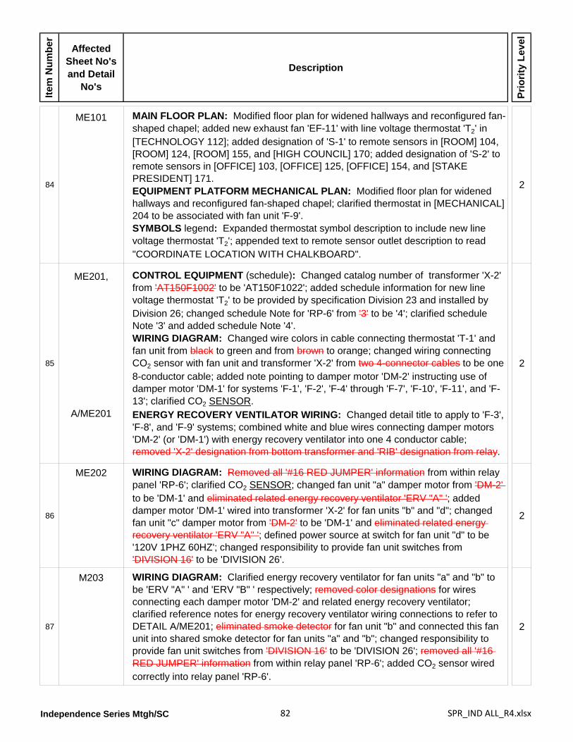
Independence Series Mtgh/SC 82 SPR_IND ALL_R4.xlsx
Item
Num
ber
Affected Sheet No's and Detail
No's
Description
Prio
rity
Leve
l
84
ME101 MAIN FLOOR PLAN: Modified floor plan for widened hallways and reconfigured fan-shaped chapel; added new exhaust fan 'EF-11' with line voltage thermostat 'T2' in [TECHNOLOGY 112]; added designation of 'S-1' to remote sensors in [ROOM] 104, [ROOM] 124, [ROOM] 155, and [HIGH COUNCIL] 170; added designation of 'S-2' to remote sensors in [OFFICE] 103, [OFFICE] 125, [OFFICE] 154, and [STAKE PRESIDENT] 171.EQUIPMENT PLATFORM MECHANICAL PLAN: Modified floor plan for widened hallways and reconfigured fan-shaped chapel; clarified thermostat in [MECHANICAL] 204 to be associated with fan unit 'F-9'.SYMBOLS legend: Expanded thermostat symbol description to include new line voltage thermostat 'T2'; appended text to remote sensor outlet description to read "COORDINATE LOCATION WITH CHALKBOARD".
2
85
ME201,
A/ME201
CONTROL EQUIPMENT (schedule): Changed catalog number of transformer 'X-2' from 'AT150F1002' to be 'AT150F1022'; added schedule information for new line voltage thermostat 'T2' to be provided by specification Division 23 and installed by Division 26; changed schedule Note for 'RP-6' from '3' to be '4'; clarified schedule Note '3' and added schedule Note '4'.WIRING DIAGRAM: Changed wire colors in cable connecting thermostat 'T-1' and fan unit from black to green and from brown to orange; changed wiring connecting CO2 sensor with fan unit and transformer 'X-2' from two 4-connector cables to be one 8-conductor cable; added note pointing to damper motor 'DM-2' instructing use of damper motor 'DM-1' for systems 'F-1', 'F-2', 'F-4' through 'F-7', 'F-10', 'F-11', and 'F-13'; clarified CO2 SENSOR.ENERGY RECOVERY VENTILATOR WIRING: Changed detail title to apply to 'F-3', 'F-8', and 'F-9' systems; combined white and blue wires connecting damper motors 'DM-2' (or 'DM-1') with energy recovery ventilator into one 4 conductor cable; removed 'X-2' designation from bottom transformer and 'RIB' designation from relay.
2
86
ME202 WIRING DIAGRAM: Removed all '#16 RED JUMPER' information from within relay panel 'RP-6'; clarified CO2 SENSOR; changed fan unit "a" damper motor from 'DM-2' to be 'DM-1' and eliminated related energy recovery ventilator 'ERV "A" '; added damper motor 'DM-1' wired into transformer 'X-2' for fan units "b" and "d"; changed fan unit "c" damper motor from 'DM-2' to be 'DM-1' and eliminated related energy recovery ventilator 'ERV "A" '; defined power source at switch for fan unit "d" to be '120V 1PHZ 60HZ'; changed responsibility to provide fan unit switches from 'DIVISION 16' to be 'DIVISION 26'.
2
87
M203 WIRING DIAGRAM: Clarified energy recovery ventilator for fan units "a" and "b" to be 'ERV "A" ' and 'ERV "B" ' respectively; removed color designations for wires connecting each damper motor 'DM-2' and related energy recovery ventilator; clarified reference notes for energy recovery ventilator wiring connections to refer to DETAIL A/ME201; eliminated smoke detector for fan unit "b" and connected this fan unit into shared smoke detector for fan units "a" and "b"; changed responsibility to provide fan unit switches from 'DIVISION 16' to be 'DIVISION 26'; removed all '#16 RED JUMPER' information from within relay panel 'RP-6'; added CO2 sensor wired correctly into relay panel 'RP-6'.
2
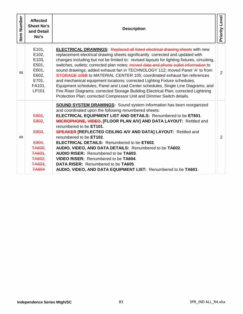
Independence Series Mtgh/SC 83 SPR_IND ALL_R4.xlsx
Item
Num
ber
Affected Sheet No's and Detail
No's
Description
Prio
rity
Leve
l
88
E101,E102,E103,E501,E601,E602,E701,
FA101,LP101
ELECTRICAL DRAWINGS: Replaced all listed electrical drawing sheets with new replacement electrical drawing sheets significantly corrected and updated with changes including but not be limited to: revised layouts for lighting fixtures, circuiting, switches, outlets; corrected plan notes; moved data and phone outlet information to sound drawings; added exhaust fan in TECHNOLOGY 112; moved Panel ‘A’ to from STORAGE 105B to MATERIAL CENTER 105; coordinated exhaust fan references and mechanical equipment locations; corrected Lighting Fixture schedules, Equipment schedules, Panel and Load Center schedules, Single Line Diagrams, and Fire Riser Diagrams; corrected Storage Building Electrical Plan; corrected Lightning Protection Plan; corrected Compressor Unit and Dimmer Switch details.
2
89
E801,E802,
E803,
E804,TA600,TA601,TA602,TA603,TA604
SOUND SYSTEM DRAWINGS: Sound system information has been reorganized and coordinated upon the following renumbered sheets:ELECTRICAL EQUIPMENT LIST AND DETAILS: Renumbered to be ET601.MICROPHONE, VIDEO, [FLOOR PLAN A/V] AND DATA LAYOUT: Retitled and renumbered to be ET101.SPEAKER [REFLECTED CEILING A/V AND DATA] LAYOUT: Retitled and renumbered to be ET102.ELECTRICAL DETAILS: Renumbered to be ET602.AUDIO, VIDEO, AND DATA DETAILS: Renumbered to be TA602.AUDIO RISER: Renumbered to be TA603.VIDEO RISER: Renumbered to be TA604.DATA RISER: Renumbered to be TA605.AUDIO, VIDEO, AND DATA EQUIPMENT LIST: Renumbered to be TA601.
2
Independence Series Mtgh/SC 84 SPR_IND ALL_R4.xlsx
Item
Num
ber
Affected Sheet No's and Detail
No's
Description
Prio
rity
Leve
l
BLANK PAGE
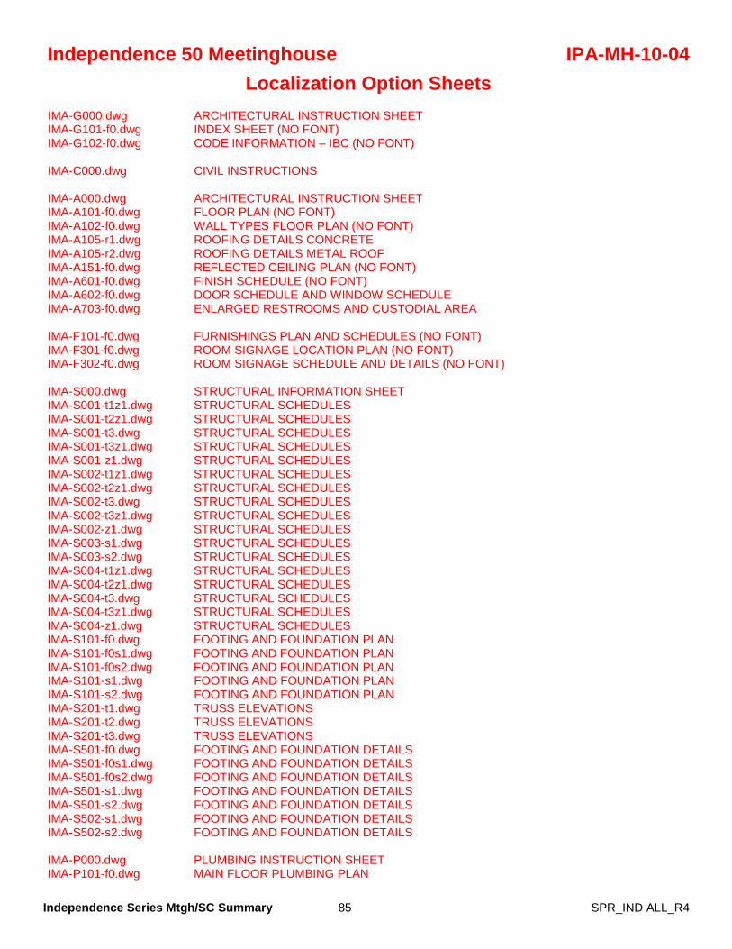
Independence Series Mtgh/SC Summary 85 SPR_IND ALL_R4
Independence 50 Meetinghouse IPA-MH-10-04 Localization Option Sheets
IMA-G000.dwg ARCHITECTURAL INSTRUCTION SHEET IMA-G101-f0.dwg INDEX SHEET (NO FONT) IMA-G102-f0.dwg CODE INFORMATION – IBC (NO FONT) IMA-C000.dwg CIVIL INSTRUCTIONS IMA-A000.dwg ARCHITECTURAL INSTRUCTION SHEET IMA-A101-f0.dwg FLOOR PLAN (NO FONT) IMA-A102-f0.dwg WALL TYPES FLOOR PLAN (NO FONT) IMA-A105-r1.dwg ROOFING DETAILS CONCRETE IMA-A105-r2.dwg ROOFING DETAILS METAL ROOF IMA-A151-f0.dwg REFLECTED CEILING PLAN (NO FONT) IMA-A601-f0.dwg FINISH SCHEDULE (NO FONT) IMA-A602-f0.dwg DOOR SCHEDULE AND WINDOW SCHEDULE IMA-A703-f0.dwg ENLARGED RESTROOMS AND CUSTODIAL AREA IMA-F101-f0.dwg FURNISHINGS PLAN AND SCHEDULES (NO FONT) IMA-F301-f0.dwg ROOM SIGNAGE LOCATION PLAN (NO FONT) IMA-F302-f0.dwg ROOM SIGNAGE SCHEDULE AND DETAILS (NO FONT) IMA-S000.dwg STRUCTURAL INFORMATION SHEET IMA-S001-t1z1.dwg STRUCTURAL SCHEDULES IMA-S001-t2z1.dwg STRUCTURAL SCHEDULES IMA-S001-t3.dwg STRUCTURAL SCHEDULES IMA-S001-t3z1.dwg STRUCTURAL SCHEDULES IMA-S001-z1.dwg STRUCTURAL SCHEDULES IMA-S002-t1z1.dwg STRUCTURAL SCHEDULES IMA-S002-t2z1.dwg STRUCTURAL SCHEDULES IMA-S002-t3.dwg STRUCTURAL SCHEDULES IMA-S002-t3z1.dwg STRUCTURAL SCHEDULES IMA-S002-z1.dwg STRUCTURAL SCHEDULES IMA-S003-s1.dwg STRUCTURAL SCHEDULES IMA-S003-s2.dwg STRUCTURAL SCHEDULES IMA-S004-t1z1.dwg STRUCTURAL SCHEDULES IMA-S004-t2z1.dwg STRUCTURAL SCHEDULES IMA-S004-t3.dwg STRUCTURAL SCHEDULES IMA-S004-t3z1.dwg STRUCTURAL SCHEDULES IMA-S004-z1.dwg STRUCTURAL SCHEDULES IMA-S101-f0.dwg FOOTING AND FOUNDATION PLAN IMA-S101-f0s1.dwg FOOTING AND FOUNDATION PLAN IMA-S101-f0s2.dwg FOOTING AND FOUNDATION PLAN IMA-S101-s1.dwg FOOTING AND FOUNDATION PLAN IMA-S101-s2.dwg FOOTING AND FOUNDATION PLAN IMA-S201-t1.dwg TRUSS ELEVATIONS IMA-S201-t2.dwg TRUSS ELEVATIONS IMA-S201-t3.dwg TRUSS ELEVATIONS IMA-S501-f0.dwg FOOTING AND FOUNDATION DETAILS IMA-S501-f0s1.dwg FOOTING AND FOUNDATION DETAILS IMA-S501-f0s2.dwg FOOTING AND FOUNDATION DETAILS IMA-S501-s1.dwg FOOTING AND FOUNDATION DETAILS IMA-S501-s2.dwg FOOTING AND FOUNDATION DETAILS IMA-S502-s1.dwg FOOTING AND FOUNDATION DETAILS IMA-S502-s2.dwg FOOTING AND FOUNDATION DETAILS IMA-P000.dwg PLUMBING INSTRUCTION SHEET IMA-P101-f0.dwg MAIN FLOOR PLUMBING PLAN
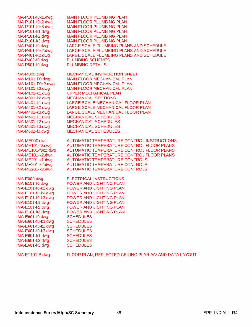
Independence Series Mtgh/SC Summary 86 SPR_IND ALL_R4
IMA-P101-f0k1.dwg MAIN FLOOR PLUMBING PLAN IMA-P101-f0k2.dwg MAIN FLOOR PLUMBING PLAN IMA-P101-f0k3.dwg MAIN FLOOR PLUMBING PLAN IMA-P101-k1.dwg MAIN FLOOR PLUMBING PLAN IMA-P101-k2.dwg MAIN FLOOR PLUMBING PLAN IMA-P101-k3.dwg MAIN FLOOR PLUMBING PLAN IMA-P401-f0.dwg LARGE SCALE PLUMBING PLANS AND SCHEDULE IMA-P401-f0k2.dwg LARGE SCALE PLUMBING PLANS AND SCHEDULE IMA-P401-K2.dwg LARGE SCALE PLUMBING PLANS AND SCHEDULE IMA-P402-f0.dwg PLUMBING SCHEMES IMA-P501-f0.dwg PLUMBING DETAILS IMA-M000.dwg MECHANICAL INSTRUCTION SHEET IMA-M101-F0.dwg MAIN FLOOR MECHANICAL PLAN IMA-M101-F0k2.dwg MAIN FLOOR MECHANICAL PLAN IMA-M101-k2.dwg MAIN FLOOR MECHANICAL PLAN IMA-M102-k1.dwg UPPER MECHANICAL PLAN IMA-M301-k2.dwg MECHANICAL SECTIONS IMA-M401-k1.dwg LARGE SCALE MECHANICAL FLOOR PLAN IMA-M401-k2.dwg LARGE SCALE MECHANICAL FLOOR PLAN IMA-M401-k3.dwg LARGE SCALE MECHANICAL FLOOR PLAN IMA-M601-k1.dwg MECHANICAL SCHEDULES IMA-M601-k2.dwg MECHANICAL SCHEDULES IMA-M601-k3.dwg MECHANICAL SCHEDULES IMA-M602-f0.dwg MECHANICAL SCHEDULES IMA-ME000.dwg AUTOMATIC TEMPERATURE CONTROL INSTRUCTIONS IMA-ME101-f0.dwg AUTOMATIC TEMPERATURE CONTROL FLOOR PLANS IMA-ME101-f0k2.dwg AUTOMATIC TEMPERATURE CONTROL FLOOR PLANS IMA-ME101-k2.dwg AUTOMATIC TEMPERATURE CONTROL FLOOR PLANS IMA-ME201-k1.dwg AUTOMATIC TEMPERATURE CONTROLS IMA-ME201-k2.dwg AUTOMATIC TEMPERATURE CONTROLS IMA-ME201-k3.dwg AUTOMATIC TEMPERATURE CONTROLS IMA-E000.dwg ELECTRICAL INSTRUCTIONS IMA-E101-f0.dwg POWER AND LIGHTING PLAN IMA-E101-f0-k1.dwg POWER AND LIGHTING PLAN IMA-E101-f0-k2.dwg POWER AND LIGHTING PLAN IMA-E101-f0-k3.dwg POWER AND LIGHTING PLAN IMA-E101-k1.dwg POWER AND LIGHTING PLAN IMA-E101-k2.dwg POWER AND LIGHTING PLAN IMA-E101-k3.dwg POWER AND LIGHTING PLAN IMA-E601-f0.dwg SCHEDULES IMA-E601-f0-k1.dwg SCHEDULES IMA-E601-f0-k2.dwg SCHEDULES IMA-E601-f0-k3.dwg SCHEDULES IMA-E601-k1.dwg SCHEDULES IMA-E601-k2.dwg SCHEDULES IMA-E601-k3.dwg SCHEDULES IMA-ET101-B.dwg FLOOR PLAN, REFLECTED CEILING PLAN A/V AND DATA LAYOUT

Independence Series Mtgh/SC Summary 87 SPR_IND ALL_R4
Independence 90 Meetinghouse IPB-MH-10-04 Localization Option Sheets
IMA-G000.dwg ARCHITECTURAL INSTRUCTIONS IMA-G101-f0.dwg INDEX SHEET (NO FONT) IMA-G102-f0.dwg CODE INFORMATION – IBC (NO FONT) IMA-C000.dwg CIVIL INSTRUCTIONS IMA-A000.dwg ARCHITECTURAL INSTRUCTIONS IMA-A101-f0.dwg FLOOR PLAN (NO FONT) IMA-A102-f0.dwg WALL TYPES FLOOR PLAN (NO FONT) IMA-A105-r1.dwg ROOF DETAILS CONCRETE IMA-A105-r2.dwg ROOF DETAILS METAL ROOF IMA-A151-f0.dwg REFLECTED CEILING PLAN (NO FONT) IMA-A601-f0.dwg FINISH SCHEDULE (NO FONT) IMA-A602-f0.dwg DOOR SCHEDULE AND WINDOW SCHEDULE (NO FONT) IMA-A703-f0.dwg ENLARGED RESTROOMS (NO FONT) IMA-F101-f0.dwg FURNISHINGS PLAN AND SCHEDULES (NO FONT) IMA-F301-f0.dwg ROOM SIGNAGE LOCATION PLAN (NO FONT) IMA-F302-f0.dwg ROOM SIGNAGE SCHEDULE AND DETAILS (NO FONT) IMA-S000.dwg STRUCTURAL INFORMATION SHEET IMA-S001-t1z1.dwg STRUCTURAL SCHEDULES IMA-S001-t2z1.dwg STRUCTURAL SCHEDULES IMA-S001-t3.dwg STRUCTURAL SCHEDULES IMA-S001-t3z1.dwg STRUCTURAL SCHEDULES IMA-S001-z1.dwg STRUCTURAL SCHEDULES IMA-S002-t1z1.dwg STRUCTURAL SCHEDULES IMA-S002-t2z1.dwg STRUCTURAL SCHEDULES IMA-S002-t3.dwg STRUCTURAL SCHEDULES IMA-S002-t3z1.dwg STRUCTURAL SCHEDULES IMA-S002-z1.dwg STRUCTURAL SCHEDULES IMA-S003-s1.dwg STRUCTURAL SCHEDULES IMA-S003-s2.dwg STRUCTURAL SCHEDULES IMA-S004-t1z1.dwg STRUCTURAL SCHEDULES IMA-S004-t2z1.dwg STRUCTURAL SCHEDULES IMA-S004-t3.dwg STRUCTURAL SCHEDULES IMA-S004-t3z1.dwg STRUCTURAL SCHEDULES IMA-S004-z1.dwg STRUCTURAL SCHEDULES IMA-S101-f0.dwg FOOTING AND FOUNDATION PLAN IMA-S101-f0s1.dwg FOOTING AND FOUNDATION PLAN IMA-S101-f0s2.dwg FOOTING AND FOUNDATION PLAN IMA-S101-s1.dwg FOOTING AND FOUNDATION PLAN IMA-S101-s2.dwg FOOTING AND FOUNDATION PLAN IMA-S201-t1.dwg TRUSS ELEVATIONS IMA-S201-t2.dwg TRUSS ELEVATIONS IMA-S201-t3.dwg TRUSS ELEVATIONS IMA-S501-f0.dwg FOOTING AND FOUNDATION DETAILS IMA-S501-f0s1.dwg FOOTING AND FOUNDATION DETAILS IMA-S501-f0s2.dwg FOOTING AND FOUNDATION DETAILS IMA-S501-s1.dwg FOOTING AND FOUNDATION DETAILS IMA-S501-s2.dwg FOOTING AND FOUNDATION DETAILS IMA-S502-s1.dwg FOOTING AND FOUNDATION DETAILS IMA-S502-s2.dwg FOOTING AND FOUNDATION DETAILS IMA-P000.dwg PLUMBING INSTRUCTION SHEET IMA-P101-f0.dwg MAIN FLOOR PLUMBING PLAN IMA-P101-f0k1.dwg MAIN FLOOR PLUMBING PLAN
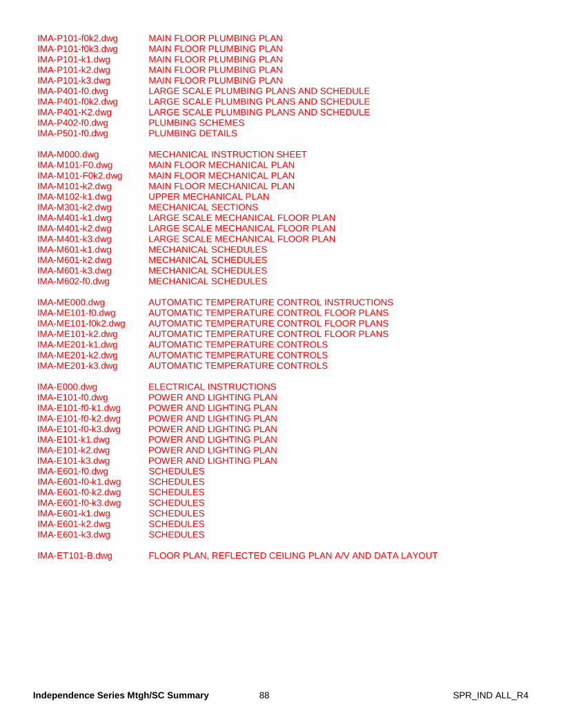
Independence Series Mtgh/SC Summary 88 SPR_IND ALL_R4
IMA-P101-f0k2.dwg MAIN FLOOR PLUMBING PLAN IMA-P101-f0k3.dwg MAIN FLOOR PLUMBING PLAN IMA-P101-k1.dwg MAIN FLOOR PLUMBING PLAN IMA-P101-k2.dwg MAIN FLOOR PLUMBING PLAN IMA-P101-k3.dwg MAIN FLOOR PLUMBING PLAN IMA-P401-f0.dwg LARGE SCALE PLUMBING PLANS AND SCHEDULE IMA-P401-f0k2.dwg LARGE SCALE PLUMBING PLANS AND SCHEDULE IMA-P401-K2.dwg LARGE SCALE PLUMBING PLANS AND SCHEDULE IMA-P402-f0.dwg PLUMBING SCHEMES IMA-P501-f0.dwg PLUMBING DETAILS IMA-M000.dwg MECHANICAL INSTRUCTION SHEET IMA-M101-F0.dwg MAIN FLOOR MECHANICAL PLAN IMA-M101-F0k2.dwg MAIN FLOOR MECHANICAL PLAN IMA-M101-k2.dwg MAIN FLOOR MECHANICAL PLAN IMA-M102-k1.dwg UPPER MECHANICAL PLAN IMA-M301-k2.dwg MECHANICAL SECTIONS IMA-M401-k1.dwg LARGE SCALE MECHANICAL FLOOR PLAN IMA-M401-k2.dwg LARGE SCALE MECHANICAL FLOOR PLAN IMA-M401-k3.dwg LARGE SCALE MECHANICAL FLOOR PLAN IMA-M601-k1.dwg MECHANICAL SCHEDULES IMA-M601-k2.dwg MECHANICAL SCHEDULES IMA-M601-k3.dwg MECHANICAL SCHEDULES IMA-M602-f0.dwg MECHANICAL SCHEDULES IMA-ME000.dwg AUTOMATIC TEMPERATURE CONTROL INSTRUCTIONS IMA-ME101-f0.dwg AUTOMATIC TEMPERATURE CONTROL FLOOR PLANS IMA-ME101-f0k2.dwg AUTOMATIC TEMPERATURE CONTROL FLOOR PLANS IMA-ME101-k2.dwg AUTOMATIC TEMPERATURE CONTROL FLOOR PLANS IMA-ME201-k1.dwg AUTOMATIC TEMPERATURE CONTROLS IMA-ME201-k2.dwg AUTOMATIC TEMPERATURE CONTROLS IMA-ME201-k3.dwg AUTOMATIC TEMPERATURE CONTROLS IMA-E000.dwg ELECTRICAL INSTRUCTIONS IMA-E101-f0.dwg POWER AND LIGHTING PLAN IMA-E101-f0-k1.dwg POWER AND LIGHTING PLAN IMA-E101-f0-k2.dwg POWER AND LIGHTING PLAN IMA-E101-f0-k3.dwg POWER AND LIGHTING PLAN IMA-E101-k1.dwg POWER AND LIGHTING PLAN IMA-E101-k2.dwg POWER AND LIGHTING PLAN IMA-E101-k3.dwg POWER AND LIGHTING PLAN IMA-E601-f0.dwg SCHEDULES IMA-E601-f0-k1.dwg SCHEDULES IMA-E601-f0-k2.dwg SCHEDULES IMA-E601-f0-k3.dwg SCHEDULES IMA-E601-k1.dwg SCHEDULES IMA-E601-k2.dwg SCHEDULES IMA-E601-k3.dwg SCHEDULES IMA-ET101-B.dwg FLOOR PLAN, REFLECTED CEILING PLAN A/V AND DATA LAYOUT
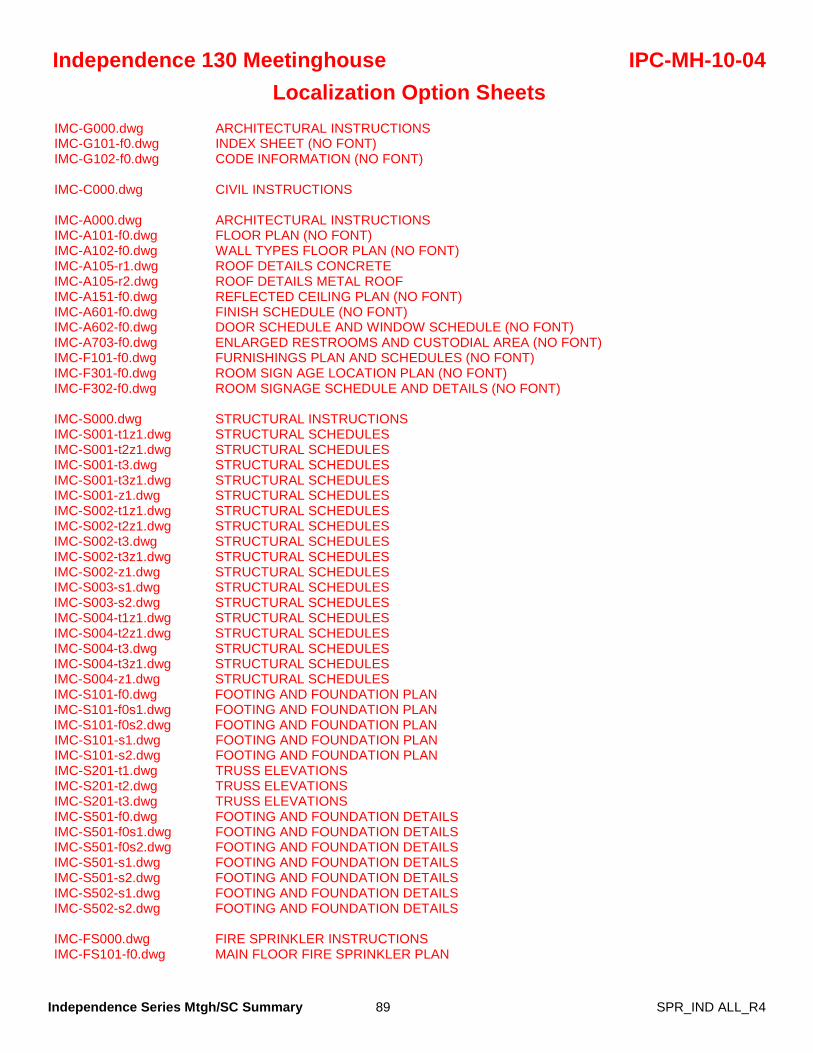
Independence Series Mtgh/SC Summary 89 SPR_IND ALL_R4
Independence 130 Meetinghouse IPC-MH-10-04 Localization Option Sheets
IMC-G000.dwg ARCHITECTURAL INSTRUCTIONS IMC-G101-f0.dwg INDEX SHEET (NO FONT) IMC-G102-f0.dwg CODE INFORMATION (NO FONT) IMC-C000.dwg CIVIL INSTRUCTIONS IMC-A000.dwg ARCHITECTURAL INSTRUCTIONS IMC-A101-f0.dwg FLOOR PLAN (NO FONT) IMC-A102-f0.dwg WALL TYPES FLOOR PLAN (NO FONT) IMC-A105-r1.dwg ROOF DETAILS CONCRETE IMC-A105-r2.dwg ROOF DETAILS METAL ROOF IMC-A151-f0.dwg REFLECTED CEILING PLAN (NO FONT) IMC-A601-f0.dwg FINISH SCHEDULE (NO FONT) IMC-A602-f0.dwg DOOR SCHEDULE AND WINDOW SCHEDULE (NO FONT) IMC-A703-f0.dwg ENLARGED RESTROOMS AND CUSTODIAL AREA (NO FONT) IMC-F101-f0.dwg FURNISHINGS PLAN AND SCHEDULES (NO FONT) IMC-F301-f0.dwg ROOM SIGN AGE LOCATION PLAN (NO FONT) IMC-F302-f0.dwg ROOM SIGNAGE SCHEDULE AND DETAILS (NO FONT) IMC-S000.dwg STRUCTURAL INSTRUCTIONS IMC-S001-t1z1.dwg STRUCTURAL SCHEDULES IMC-S001-t2z1.dwg STRUCTURAL SCHEDULES IMC-S001-t3.dwg STRUCTURAL SCHEDULES IMC-S001-t3z1.dwg STRUCTURAL SCHEDULES IMC-S001-z1.dwg STRUCTURAL SCHEDULES IMC-S002-t1z1.dwg STRUCTURAL SCHEDULES IMC-S002-t2z1.dwg STRUCTURAL SCHEDULES IMC-S002-t3.dwg STRUCTURAL SCHEDULES IMC-S002-t3z1.dwg STRUCTURAL SCHEDULES IMC-S002-z1.dwg STRUCTURAL SCHEDULES IMC-S003-s1.dwg STRUCTURAL SCHEDULES IMC-S003-s2.dwg STRUCTURAL SCHEDULES IMC-S004-t1z1.dwg STRUCTURAL SCHEDULES IMC-S004-t2z1.dwg STRUCTURAL SCHEDULES IMC-S004-t3.dwg STRUCTURAL SCHEDULES IMC-S004-t3z1.dwg STRUCTURAL SCHEDULES IMC-S004-z1.dwg STRUCTURAL SCHEDULES IMC-S101-f0.dwg FOOTING AND FOUNDATION PLAN IMC-S101-f0s1.dwg FOOTING AND FOUNDATION PLAN IMC-S101-f0s2.dwg FOOTING AND FOUNDATION PLAN IMC-S101-s1.dwg FOOTING AND FOUNDATION PLAN IMC-S101-s2.dwg FOOTING AND FOUNDATION PLAN IMC-S201-t1.dwg TRUSS ELEVATIONS IMC-S201-t2.dwg TRUSS ELEVATIONS IMC-S201-t3.dwg TRUSS ELEVATIONS IMC-S501-f0.dwg FOOTING AND FOUNDATION DETAILS IMC-S501-f0s1.dwg FOOTING AND FOUNDATION DETAILS IMC-S501-f0s2.dwg FOOTING AND FOUNDATION DETAILS IMC-S501-s1.dwg FOOTING AND FOUNDATION DETAILS IMC-S501-s2.dwg FOOTING AND FOUNDATION DETAILS IMC-S502-s1.dwg FOOTING AND FOUNDATION DETAILS IMC-S502-s2.dwg FOOTING AND FOUNDATION DETAILS IMC-FS000.dwg FIRE SPRINKLER INSTRUCTIONS IMC-FS101-f0.dwg MAIN FLOOR FIRE SPRINKLER PLAN
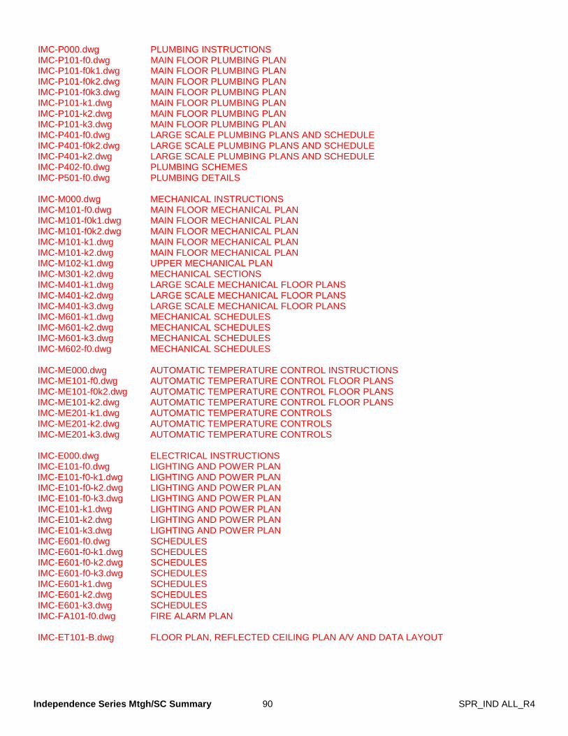
Independence Series Mtgh/SC Summary 90 SPR_IND ALL_R4
IMC-P000.dwg PLUMBING INSTRUCTIONS IMC-P101-f0.dwg MAIN FLOOR PLUMBING PLAN IMC-P101-f0k1.dwg MAIN FLOOR PLUMBING PLAN IMC-P101-f0k2.dwg MAIN FLOOR PLUMBING PLAN IMC-P101-f0k3.dwg MAIN FLOOR PLUMBING PLAN IMC-P101-k1.dwg MAIN FLOOR PLUMBING PLAN IMC-P101-k2.dwg MAIN FLOOR PLUMBING PLAN IMC-P101-k3.dwg MAIN FLOOR PLUMBING PLAN IMC-P401-f0.dwg LARGE SCALE PLUMBING PLANS AND SCHEDULE IMC-P401-f0k2.dwg LARGE SCALE PLUMBING PLANS AND SCHEDULE IMC-P401-k2.dwg LARGE SCALE PLUMBING PLANS AND SCHEDULE IMC-P402-f0.dwg PLUMBING SCHEMES IMC-P501-f0.dwg PLUMBING DETAILS IMC-M000.dwg MECHANICAL INSTRUCTIONS IMC-M101-f0.dwg MAIN FLOOR MECHANICAL PLAN IMC-M101-f0k1.dwg MAIN FLOOR MECHANICAL PLAN IMC-M101-f0k2.dwg MAIN FLOOR MECHANICAL PLAN IMC-M101-k1.dwg MAIN FLOOR MECHANICAL PLAN IMC-M101-k2.dwg MAIN FLOOR MECHANICAL PLAN IMC-M102-k1.dwg UPPER MECHANICAL PLAN IMC-M301-k2.dwg MECHANICAL SECTIONS IMC-M401-k1.dwg LARGE SCALE MECHANICAL FLOOR PLANS IMC-M401-k2.dwg LARGE SCALE MECHANICAL FLOOR PLANS IMC-M401-k3.dwg LARGE SCALE MECHANICAL FLOOR PLANS IMC-M601-k1.dwg MECHANICAL SCHEDULES IMC-M601-k2.dwg MECHANICAL SCHEDULES IMC-M601-k3.dwg MECHANICAL SCHEDULES IMC-M602-f0.dwg MECHANICAL SCHEDULES IMC-ME000.dwg AUTOMATIC TEMPERATURE CONTROL INSTRUCTIONS IMC-ME101-f0.dwg AUTOMATIC TEMPERATURE CONTROL FLOOR PLANS IMC-ME101-f0k2.dwg AUTOMATIC TEMPERATURE CONTROL FLOOR PLANS IMC-ME101-k2.dwg AUTOMATIC TEMPERATURE CONTROL FLOOR PLANS IMC-ME201-k1.dwg AUTOMATIC TEMPERATURE CONTROLS IMC-ME201-k2.dwg AUTOMATIC TEMPERATURE CONTROLS IMC-ME201-k3.dwg AUTOMATIC TEMPERATURE CONTROLS IMC-E000.dwg ELECTRICAL INSTRUCTIONS IMC-E101-f0.dwg LIGHTING AND POWER PLAN IMC-E101-f0-k1.dwg LIGHTING AND POWER PLAN IMC-E101-f0-k2.dwg LIGHTING AND POWER PLAN IMC-E101-f0-k3.dwg LIGHTING AND POWER PLAN IMC-E101-k1.dwg LIGHTING AND POWER PLAN IMC-E101-k2.dwg LIGHTING AND POWER PLAN IMC-E101-k3.dwg LIGHTING AND POWER PLAN IMC-E601-f0.dwg SCHEDULES IMC-E601-f0-k1.dwg SCHEDULES IMC-E601-f0-k2.dwg SCHEDULES IMC-E601-f0-k3.dwg SCHEDULES IMC-E601-k1.dwg SCHEDULES IMC-E601-k2.dwg SCHEDULES IMC-E601-k3.dwg SCHEDULES IMC-FA101-f0.dwg FIRE ALARM PLAN IMC-ET101-B.dwg FLOOR PLAN, REFLECTED CEILING PLAN A/V AND DATA LAYOUT
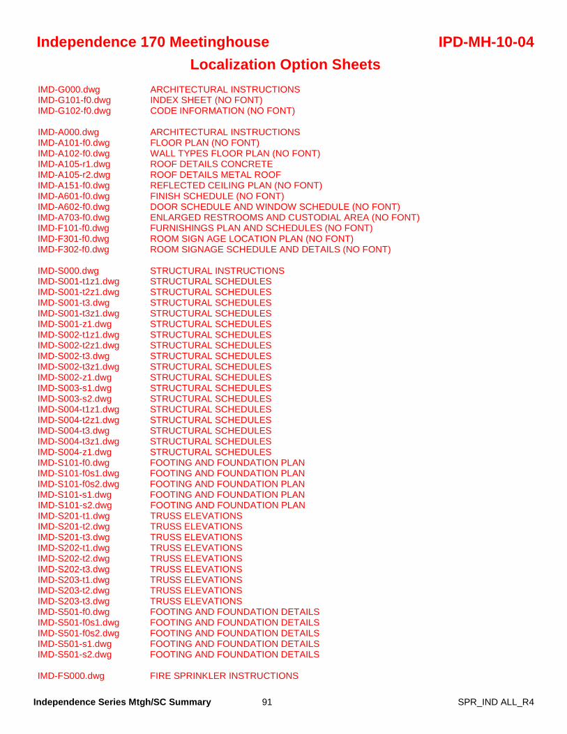
Independence Series Mtgh/SC Summary 91 SPR_IND ALL_R4
Independence 170 Meetinghouse IPD-MH-10-04 Localization Option Sheets
IMD-G000.dwg ARCHITECTURAL INSTRUCTIONS IMD-G101-f0.dwg INDEX SHEET (NO FONT) IMD-G102-f0.dwg CODE INFORMATION (NO FONT) IMD-A000.dwg ARCHITECTURAL INSTRUCTIONS IMD-A101-f0.dwg FLOOR PLAN (NO FONT) IMD-A102-f0.dwg WALL TYPES FLOOR PLAN (NO FONT) IMD-A105-r1.dwg ROOF DETAILS CONCRETE IMD-A105-r2.dwg ROOF DETAILS METAL ROOF IMD-A151-f0.dwg REFLECTED CEILING PLAN (NO FONT) IMD-A601-f0.dwg FINISH SCHEDULE (NO FONT) IMD-A602-f0.dwg DOOR SCHEDULE AND WINDOW SCHEDULE (NO FONT) IMD-A703-f0.dwg ENLARGED RESTROOMS AND CUSTODIAL AREA (NO FONT) IMD-F101-f0.dwg FURNISHINGS PLAN AND SCHEDULES (NO FONT) IMD-F301-f0.dwg ROOM SIGN AGE LOCATION PLAN (NO FONT) IMD-F302-f0.dwg ROOM SIGNAGE SCHEDULE AND DETAILS (NO FONT) IMD-S000.dwg STRUCTURAL INSTRUCTIONS IMD-S001-t1z1.dwg STRUCTURAL SCHEDULES IMD-S001-t2z1.dwg STRUCTURAL SCHEDULES IMD-S001-t3.dwg STRUCTURAL SCHEDULES IMD-S001-t3z1.dwg STRUCTURAL SCHEDULES IMD-S001-z1.dwg STRUCTURAL SCHEDULES IMD-S002-t1z1.dwg STRUCTURAL SCHEDULES IMD-S002-t2z1.dwg STRUCTURAL SCHEDULES IMD-S002-t3.dwg STRUCTURAL SCHEDULES IMD-S002-t3z1.dwg STRUCTURAL SCHEDULES IMD-S002-z1.dwg STRUCTURAL SCHEDULES IMD-S003-s1.dwg STRUCTURAL SCHEDULES IMD-S003-s2.dwg STRUCTURAL SCHEDULES IMD-S004-t1z1.dwg STRUCTURAL SCHEDULES IMD-S004-t2z1.dwg STRUCTURAL SCHEDULES IMD-S004-t3.dwg STRUCTURAL SCHEDULES IMD-S004-t3z1.dwg STRUCTURAL SCHEDULES IMD-S004-z1.dwg STRUCTURAL SCHEDULES IMD-S101-f0.dwg FOOTING AND FOUNDATION PLAN IMD-S101-f0s1.dwg FOOTING AND FOUNDATION PLAN IMD-S101-f0s2.dwg FOOTING AND FOUNDATION PLAN IMD-S101-s1.dwg FOOTING AND FOUNDATION PLAN IMD-S101-s2.dwg FOOTING AND FOUNDATION PLAN IMD-S201-t1.dwg TRUSS ELEVATIONS IMD-S201-t2.dwg TRUSS ELEVATIONS IMD-S201-t3.dwg TRUSS ELEVATIONS IMD-S202-t1.dwg TRUSS ELEVATIONS IMD-S202-t2.dwg TRUSS ELEVATIONS IMD-S202-t3.dwg TRUSS ELEVATIONS IMD-S203-t1.dwg TRUSS ELEVATIONS IMD-S203-t2.dwg TRUSS ELEVATIONS IMD-S203-t3.dwg TRUSS ELEVATIONS IMD-S501-f0.dwg FOOTING AND FOUNDATION DETAILS IMD-S501-f0s1.dwg FOOTING AND FOUNDATION DETAILS IMD-S501-f0s2.dwg FOOTING AND FOUNDATION DETAILS IMD-S501-s1.dwg FOOTING AND FOUNDATION DETAILS IMD-S501-s2.dwg FOOTING AND FOUNDATION DETAILS IMD-FS000.dwg FIRE SPRINKLER INSTRUCTIONS
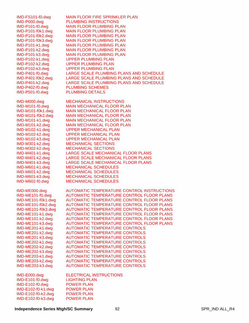
Independence Series Mtgh/SC Summary 92 SPR_IND ALL_R4
IMD-FS101-f0.dwg MAIN FLOOR FIRE SPRINKLER PLAN IMD-P000.dwg PLUMBING INSTRUCTIONS IMD-P101-f0.dwg MAIN FLOOR PLUMBING PLAN IMD-P101-f0k1.dwg MAIN FLOOR PLUMBING PLAN IMD-P101-f0k2.dwg MAIN FLOOR PLUMBING PLAN IMD-P101-f0k3.dwg MAIN FLOOR PLUMBING PLAN IMD-P101-k1.dwg MAIN FLOOR PLUMBING PLAN IMD-P101-k2.dwg MAIN FLOOR PLUMBING PLAN IMD-P101-k3.dwg MAIN FLOOR PLUMBING PLAN IMD-P102-k1.dwg UPPER PLUMBING PLAN IMD-P102-k2.dwg UPPER PLUMBING PLAN IMD-P102-k3.dwg UPPER PLUMBING PLAN IMD-P401-f0.dwg LARGE SCALE PLUMBING PLANS AND SCHEDULE IMD-P401-f0k2.dwg LARGE SCALE PLUMBING PLANS AND SCHEDULE IMD-P401-k2.dwg LARGE SCALE PLUMBING PLANS AND SCHEDULE IMD-P402-f0.dwg PLUMBING SCHEMES IMD-P501-f0.dwg PLUMBING DETAILS IMD-M000.dwg MECHANICAL INSTRUCTIONS IMD-M101-f0.dwg MAIN MECHANICAL FLOOR PLAN IMD-M101-f0k1.dwg MAIN MECHANICAL FLOOR PLAN IMD-M101-f0k2.dwg MAIN MECHANICAL FLOOR PLAN IMD-M101-k1.dwg MAIN MECHANICAL FLOOR PLAN IMD-M101-k2.dwg MAIN MECHANICAL FLOOR PLAN IMD-M102-k1.dwg UPPER MECHANICAL PLAN IMD-M102-k2.dwg UPPER MECHANICAL PLAN IMD-M102-k3.dwg UPPER MECHANICAL PLAN IMD-M301-k2.dwg MECHANICAL SECTIONS IMD-M302-k2.dwg MECHANICAL SECTIONS IMD-M401-k1.dwg LARGE SCALE MECHANICAL FLOOR PLANS IMD-M401-k2.dwg LARGE SCALE MECHANICAL FLOOR PLANS IMD-M401-k3.dwg LARGE SCALE MECHANICAL FLOOR PLANS IMD-M601-k1.dwg MECHANICAL SCHEDULES IMD-M601-k2.dwg MECHANICAL SCHEDULES IMD-M601-k3.dwg MECHANICAL SCHEDULES IMD-M602-f0.dwg MECHANICAL SCHEDULES IMD-ME000.dwg AUTOMATIC TEMPERATURE CONTROL INSTRUCTIONS IMD-ME101-f0.dwg AUTOMATIC TEMPERATURE CONTROL FLOOR PLANS IMD-ME101-f0k1.dwg AUTOMATIC TEMPERATURE CONTROL FLOOR PLANS IMD-ME101-f0k2.dwg AUTOMATIC TEMPERATURE CONTROL FLOOR PLANS IMD-ME101-f0k3.dwg AUTOMATIC TEMPERATURE CONTROL FLOOR PLANS IMD-ME101-k1.dwg AUTOMATIC TEMPERATURE CONTROL FLOOR PLANS IMD-ME101-k2.dwg AUTOMATIC TEMPERATURE CONTROL FLOOR PLANS IMD-ME101-k3.dwg AUTOMATIC TEMPERATURE CONTROL FLOOR PLANS IMD-ME201-k1.dwg AUTOMATIC TEMPERATURE CONTROLS IMD-ME201-k2.dwg AUTOMATIC TEMPERATURE CONTROLS IMD-ME201-k3.dwg AUTOMATIC TEMPERATURE CONTROLS IMD-ME202-k1.dwg AUTOMATIC TEMPERATURE CONTROLS IMD-ME202-k2.dwg AUTOMATIC TEMPERATURE CONTROLS IMD-ME202-k3.dwg AUTOMATIC TEMPERATURE CONTROLS IMD-ME203-k1.dwg AUTOMATIC TEMPERATURE CONTROLS IMD-ME203-k2.dwg AUTOMATIC TEMPERATURE CONTROLS IMD-ME203-k3.dwg AUTOMATIC TEMPERATURE CONTROLS IMD-E000.dwg ELECTRICAL INSTRUCTIONS IMD-E101-f0.dwg LIGHTING PLAN IMD-E102-f0.dwg POWER PLAN IMD-E102-f0-k1.dwg POWER PLAN IMD-E102-f0-k2.dwg POWER PLAN IMD-E102-f0-k3.dwg POWER PLAN
Independence Series Mtgh/SC Summary 93 SPR_IND ALL_R4
IMD-E102-k1.dwg POWER PLAN IMD-E102-k2.dwg POWER PLAN IMD-E102-k3.dwg POWER PLAN IMD-E103-k1.dwg MECHANICAL ACCESS AND ATTIC POWER PLAN IMD-E103-k2.dwg MECHANICAL ACCESS AND ATTIC POWER PLAN IMD-E103-k3.dwg MECHANICAL ACCESS AND ATTIC POWER PLAN IMD-E601-F0.dwg LIGHT FIXTURE SCHEDULE MECHANICAL EQUIPMENT SCHEDULE IMD-E601-f0-k1.dwg LIGHT FIXTURE SCHEDULE MECHANICAL EQUIPMENT SCHEDULE IMD-E601-f0-k2.dwg LIGHT FIXTURE SCHEDULE MECHANICAL EQUIPMENT SCHEDULE IMD-E601-f0-k3.dwg LIGHT FIXTURE SCHEDULE MECHANICAL EQUIPMENT SCHEDULE IMD-E601-k1.dwg LIGHT FIXTURE SCHEDULE MECHANICAL EQUIPMENT SCHEDULE IMD-E601-k2.dwg LIGHT FIXTURE SCHEDULE MECHANICAL EQUIPMENT SCHEDULE IMD-E601-k3.dwg LIGHT FIXTURE SCHEDULE MECHANICAL EQUIPMENT SCHEDULE IMD-E602-f0.dwg SINGLE-LINE DIAGRAM AND PANELBOARD SCHEDULES IMD-E602-f0-k1.dwg SINGLE-LINE DIAGRAM AND PANELBOARD SCHEDULES IMD-E602-f0-k2.dwg SINGLE-LINE DIAGRAM AND PANELBOARD SCHEDULES IMD-E602-f0-k3.dwg SINGLE-LINE DIAGRAM AND PANELBOARD SCHEDULES IMD-E602-k1.dwg SINGLE-LINE DIAGRAM AND PANELBOARD SCHEDULES IMD-E602-k2.dwg SINGLE-LINE DIAGRAM AND PANELBOARD SCHEDULES IMD-E602-k3.dwg SINGLE-LINE DIAGRAM AND PANELBOARD SCHEDULES IMD-FA101-f0.dwg FIRE ALARM PLAN IMD-ET101-f0.dwg FLOOR PLAN AUDIO/VIDEO AND DATA LAYOUT IMD-ET102-f0.dwg REFLECTED CEILING AUDIO/VIDEO AND DATA LAYOUT
Independence Series Mtgh/SC Summary 94 SPR_IND ALL_R4
BLANK PAGE
Independence Series Mtgh/SC Summary 95 SPR_IND ALL_R4
Independence 230 Meetinghouse IPE-MH-10-04 Localization Option Sheets
IME-G000.dwg ARCHITECTURAL INSTRUCTIONS IME-G101-f0.dwg INDEX SHEET (NO FONT) IME-G102-f0.dwg CODE INFORMATION (NO FONT) IME-C000.dwg CIVIL INSTRUCTIONS IME-A000.dwg ARCHITECTURAL INSTRUCTIONS IME-A101-f0.dwg FLOOR PLAN (NO FONT) IME-A102-f0.dwg WALL TYPES IME-A105-r1.dwg ROOF DETAILS CONCRETE IME-A105-r2.dwg ROOF DETAILS METAL ROOF IME-A151-f0.dwg REFLECTED CEILING PLAN (NO FONT) IME-A601-f0.dwg FINISH SCHEDULE (NO FONT) IME-A602-f0.dwg DOOR SCHEDULE AND WINDOW SCHEDULE (NO FONT) IME-A703-f0.dwg ENLARGED RESTROOMS AND CUSTODIAL AREA (NO FONT) IME-F101-f0.dwg FURNISHINGS PLAN AND SCHEDULES (NO FONT) IME-F301-f0.dwg ROOM SIGN AGE LOCATION PLAN (NO FONT) IME-F302-f0.dwg ROOM SIGNAGE SCHEDULE AND DETAILS (NO FONT) IME-S000.dwg STRUCTURAL INSTRUCTIONS IME-S001-t1z1.dwg STRUCTURAL SCHEDULES IME-S001-t2z1.dwg STRUCTURAL SCHEDULES IME-S001-t3.dwg STRUCTURAL SCHEDULES IME-S001-t3z1.dwg STRUCTURAL SCHEDULES IME-S001-z1.dwg STRUCTURAL SCHEDULES IME-S002-t1z1.dwg STRUCTURAL SCHEDULES IME-S002-t2z1.dwg STRUCTURAL SCHEDULES IME-S002-t3.dwg STRUCTURAL SCHEDULES IME-S002-t3z1.dwg STRUCTURAL SCHEDULES IME-S002-z1.dwg STRUCTURAL SCHEDULES IME-S003-s1.dwg STRUCTURAL SCHEDULES IME-S003-s2.dwg STRUCTURAL SCHEDULES IME-S004-t1z1.dwg STRUCTURAL SCHEDULES IME-S004-t2z1.dwg STRUCTURAL SCHEDULES IME-S004-t3.dwg STRUCTURAL SCHEDULES IME-S004-t3z1.dwg STRUCTURAL SCHEDULES IME-S004-z1.dwg STRUCTURAL SCHEDULES IME-S101-f0.dwg FOOTING AND FOUNDATION PLAN IME-S101-f0s1.dwg FOOTING AND FOUNDATION PLAN IME-S101-f0s2.dwg FOOTING AND FOUNDATION PLAN IME-S101-s1.dwg FOOTING AND FOUNDATION PLAN IME-S101-s2.dwg FOOTING AND FOUNDATION PLAN IME-S201-t1.dwg TRUSS ELEVATIONS IME-S201-t2.dwg TRUSS ELEVATIONS IME-S201-t3.dwg TRUSS ELEVATIONS IME-S202-t1.dwg TRUSS ELEVATIONS IME-S202-t2.dwg TRUSS ELEVATIONS IME-S202-t3.dwg TRUSS ELEVATIONS IME-S203-t2.dwg TRUSS ELEVATIONS IME-S203-t3.dwg TRUSS ELEVATIONS IME-S204-t1.dwg TRUSS ELEVATIONS IME-S204-t2.dwg TRUSS ELEVATIONS IME-S204-t3.dwg TRUSS ELEVATIONS IME-S501-f0.dwg FOOTING AND FOUNDATION DETAILS IME-S501-f0s1.dwg FOOTING AND FOUNDATION DETAILS IME-S501-f0s2.dwg FOOTING AND FOUNDATION DETAILS
Independence Series Mtgh/SC Summary 96 SPR_IND ALL_R4
IME-S501-s1.dwg FOOTING AND FOUNDATION DETAILS IME-S501-s2.dwg FOOTING AND FOUNDATION DETAILS IME-S502-s1.dwg FOOTING AND FOUNDATION DETAILS IME-S502-s2.dwg FOOTING AND FOUNDATION DETAILS IME-FS000.dwg FIRE SPRINKLER INSTRUCTIONS IME-FS101-f0.dwg MAIN FLOOR FIRE SPRINKLER PLAN IME-P000.dwg PLUMBING INSTRUCTIONS IME-P101-f0.dwg MAIN FLOOR PLUMBING PLAN IME-P101-f0k1.dwg MAIN FLOOR PLUMBING PLAN IME-P101-f0k2.dwg MAIN FLOOR PLUMBING PLAN IME-P101-f0k3.dwg MAIN FLOOR PLUMBING PLAN IME-P101-k1.dwg MAIN FLOOR PLUMBING PLAN IME-P101-k2.dwg MAIN FLOOR PLUMBING PLAN IME-P101-k3.dwg MAIN FLOOR PLUMBING PLAN IME-P102-k1.dwg EQUIPMENT PLATFORM PLUMBING PLAN IME-P102-k2.dwg EQUIPMENT PLATFORM PLUMBING PLAN IME-P102-k3.dwg EQUIPMENT PLATFORM PLUMBING PLAN IME-P401-f0.dwg LARGE SCALE PLUMBING PLANS AND SCHEDULE IME-P401-f0k2.dwg LARGE SCALE PLUMBING PLANS AND SCHEDULE IME-P401-k2.dwg LARGE SCALE PLUMBING PLANS AND SCHEDULE IME-P402-f0.dwg PLUMBING SCHEMES IME-P501-f0.dwg PLUMBING DETAILS IME-M000.dwg MECHANICAL INSTRUCTIONS IME-M101-f0.dwg MAIN FLOOR MECHANICAL PLAN IME-M101-f0k1.dwg MAIN FLOOR MECHANICAL PLAN IME-M101-f0k2.dwg MAIN FLOOR MECHANICAL PLAN IME-M101-k1.dwg MAIN FLOOR MECHANICAL PLAN IME-M101-k2.dwg MAIN FLOOR MECHANICAL PLAN IME-M102-k1.dwg EQUIPMENT PLATFORM MECHANICAL PLAN IME-M102-k2.dwg EQUIPMENT PLATFORM MECHANICAL PLAN IME-M102-k3.dwg EQUIPMENT PLATFORM MECHANICAL PLAN IME-M301-k2.dwg MECHANICAL SECTIONS IME-M302-k2.dwg MECHANICAL SECTIONS IME-M401-k1.dwg LARGE SCALE MECHANICAL FLOOR PLANS IME-M401-k2.dwg LARGE SCALE MECHANICAL FLOOR PLANS IME-M401-k3.dwg LARGE SCALE MECHANICAL FLOOR PLANS IME-M601-k1.dwg MECHANICAL SCHEDULES IME-M601-k2.dwg MECHANICAL SCHEDULES IME-M601-k3.dwg MECHANICAL SCHEDULES IME-M602-f0.dwg MECHANICAL SCHEDULES IME-ME000.dwg AUTOMATIC TEMPERATURE CONTROL INSTRUCTIONS IME-ME101-f0.dwg AUTOMATIC TEMPERATURE CONTROL FLOOR PLANS IME-ME101-f0k1.dwg AUTOMATIC TEMPERATURE CONTROL FLOOR PLANS IME-ME101-f0k2.dwg AUTOMATIC TEMPERATURE CONTROL FLOOR PLANS IME-ME101-f0k3.dwg AUTOMATIC TEMPERATURE CONTROL FLOOR PLANS IME-ME101-k1.dwg AUTOMATIC TEMPERATURE CONTROL FLOOR PLANS IME-ME101-k2.dwg AUTOMATIC TEMPERATURE CONTROL FLOOR PLANS IME-ME101-k3.dwg AUTOMATIC TEMPERATURE CONTROL FLOOR PLANS IME-ME201-k1.dwg AUTOMATIC TEMPERATURE CONTROLS IME-ME201-k2.dwg AUTOMATIC TEMPERATURE CONTROLS IME-ME201-k3.dwg AUTOMATIC TEMPERATURE CONTROLS IME-ME202-k1.dwg AUTOMATIC TEMPERATURE CONTROLS IME-ME202-k2.dwg AUTOMATIC TEMPERATURE CONTROLS IME-ME202-k3.dwg AUTOMATIC TEMPERATURE CONTROLS IME-ME203-k1.dwg AUTOMATIC TEMPERATURE CONTROLS IME-ME203-k2.dwg AUTOMATIC TEMPERATURE CONTROLS IME-ME203-k3.dwg AUTOMATIC TEMPERATURE CONTROLS
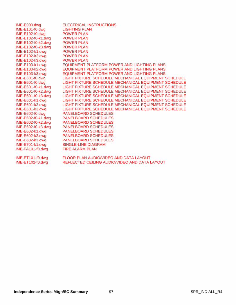
Independence Series Mtgh/SC Summary 97 SPR_IND ALL_R4
IME-E000.dwg ELECTRICAL INSTRUCTIONS IME-E101-f0.dwg LIGHTING PLAN IME-E102-f0.dwg POWER PLAN IME-E102-f0-k1.dwg POWER PLAN IME-E102-f0-k2.dwg POWER PLAN IME-E102-f0-k3.dwg POWER PLAN IME-E102-k1.dwg POWER PLAN IME-E102-k2.dwg POWER PLAN IME-E102-k3.dwg POWER PLAN IME-E103-k1.dwg EQUIPMENT PLATFORM POWER AND LIGHTING PLANS IME-E103-k2.dwg EQUIPMENT PLATFORM POWER AND LIGHTING PLANS IME-E103-k3.dwg EQUIPMENT PLATFORM POWER AND LIGHTING PLANS IME-E601-f0.dwg LIGHT FIXTURE SCHEDULE MECHANICAL EQUIPMENT SCHEDULE IME-E601-f0.dwg LIGHT FIXTURE SCHEDULE MECHANICAL EQUIPMENT SCHEDULE IME-E601-f0-k1.dwg LIGHT FIXTURE SCHEDULE MECHANICAL EQUIPMENT SCHEDULE IME-E601-f0-k2.dwg LIGHT FIXTURE SCHEDULE MECHANICAL EQUIPMENT SCHEDULE IME-E601-f0-k3.dwg LIGHT FIXTURE SCHEDULE MECHANICAL EQUIPMENT SCHEDULE IME-E601-k1.dwg LIGHT FIXTURE SCHEDULE MECHANICAL EQUIPMENT SCHEDULE IME-E601-k2.dwg LIGHT FIXTURE SCHEDULE MECHANICAL EQUIPMENT SCHEDULE IME-E601-k3.dwg LIGHT FIXTURE SCHEDULE MECHANICAL EQUIPMENT SCHEDULE IME-E602-f0.dwg PANELBOARD SCHEDULES IME-E602-f0-k1.dwg PANELBOARD SCHEDULES IME-E602-f0-k2.dwg PANELBOARD SCHEDULES IME-E602-f0-k3.dwg PANELBOARD SCHEDULES IME-E602-k1.dwg PANELBOARD SCHEDULES IME-E602-k2.dwg PANELBOARD SCHEDULES IME-E602-k3.dwg PANELBOARD SCHEDULES IME-E701-k1.dwg SINGLE-LINE DIAGRAM IME-FA101-f0.dwg FIRE ALARM PLAN IME-ET101-f0.dwg FLOOR PLAN AUDIO/VIDEO AND DATA LAYOUT IME-ET102-f0.dwg REFLECTED CEILING AUDIO/VIDEO AND DATA LAYOUT

Independence Series Mtgh/SC Summary 98 SPR_IND ALL_R4
BLANK PAGE
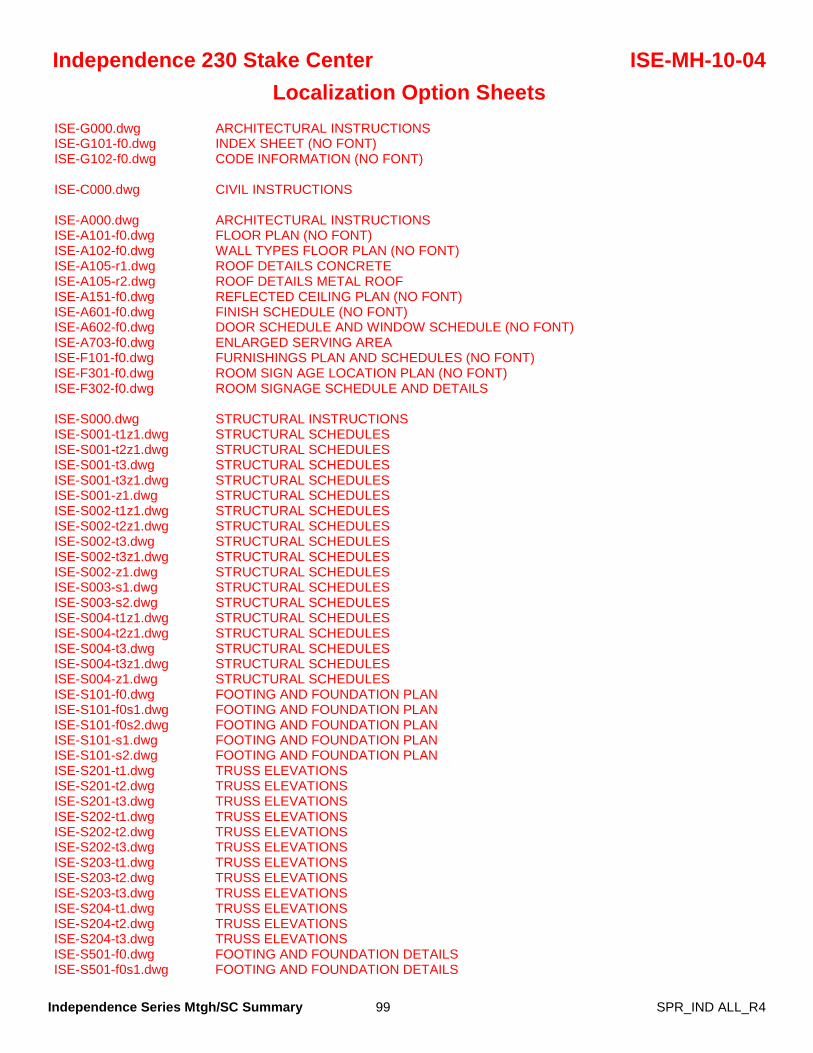
Independence Series Mtgh/SC Summary 99 SPR_IND ALL_R4
Independence 230 Stake Center ISE-MH-10-04 Localization Option Sheets
ISE-G000.dwg ARCHITECTURAL INSTRUCTIONS ISE-G101-f0.dwg INDEX SHEET (NO FONT) ISE-G102-f0.dwg CODE INFORMATION (NO FONT) ISE-C000.dwg CIVIL INSTRUCTIONS ISE-A000.dwg ARCHITECTURAL INSTRUCTIONS ISE-A101-f0.dwg FLOOR PLAN (NO FONT) ISE-A102-f0.dwg WALL TYPES FLOOR PLAN (NO FONT) ISE-A105-r1.dwg ROOF DETAILS CONCRETE ISE-A105-r2.dwg ROOF DETAILS METAL ROOF ISE-A151-f0.dwg REFLECTED CEILING PLAN (NO FONT) ISE-A601-f0.dwg FINISH SCHEDULE (NO FONT) ISE-A602-f0.dwg DOOR SCHEDULE AND WINDOW SCHEDULE (NO FONT) ISE-A703-f0.dwg ENLARGED SERVING AREA ISE-F101-f0.dwg FURNISHINGS PLAN AND SCHEDULES (NO FONT) ISE-F301-f0.dwg ROOM SIGN AGE LOCATION PLAN (NO FONT) ISE-F302-f0.dwg ROOM SIGNAGE SCHEDULE AND DETAILS ISE-S000.dwg STRUCTURAL INSTRUCTIONS ISE-S001-t1z1.dwg STRUCTURAL SCHEDULES ISE-S001-t2z1.dwg STRUCTURAL SCHEDULES ISE-S001-t3.dwg STRUCTURAL SCHEDULES ISE-S001-t3z1.dwg STRUCTURAL SCHEDULES ISE-S001-z1.dwg STRUCTURAL SCHEDULES ISE-S002-t1z1.dwg STRUCTURAL SCHEDULES ISE-S002-t2z1.dwg STRUCTURAL SCHEDULES ISE-S002-t3.dwg STRUCTURAL SCHEDULES ISE-S002-t3z1.dwg STRUCTURAL SCHEDULES ISE-S002-z1.dwg STRUCTURAL SCHEDULES ISE-S003-s1.dwg STRUCTURAL SCHEDULES ISE-S003-s2.dwg STRUCTURAL SCHEDULES ISE-S004-t1z1.dwg STRUCTURAL SCHEDULES ISE-S004-t2z1.dwg STRUCTURAL SCHEDULES ISE-S004-t3.dwg STRUCTURAL SCHEDULES ISE-S004-t3z1.dwg STRUCTURAL SCHEDULES ISE-S004-z1.dwg STRUCTURAL SCHEDULES ISE-S101-f0.dwg FOOTING AND FOUNDATION PLAN ISE-S101-f0s1.dwg FOOTING AND FOUNDATION PLAN ISE-S101-f0s2.dwg FOOTING AND FOUNDATION PLAN ISE-S101-s1.dwg FOOTING AND FOUNDATION PLAN ISE-S101-s2.dwg FOOTING AND FOUNDATION PLAN ISE-S201-t1.dwg TRUSS ELEVATIONS ISE-S201-t2.dwg TRUSS ELEVATIONS ISE-S201-t3.dwg TRUSS ELEVATIONS ISE-S202-t1.dwg TRUSS ELEVATIONS ISE-S202-t2.dwg TRUSS ELEVATIONS ISE-S202-t3.dwg TRUSS ELEVATIONS ISE-S203-t1.dwg TRUSS ELEVATIONS ISE-S203-t2.dwg TRUSS ELEVATIONS ISE-S203-t3.dwg TRUSS ELEVATIONS ISE-S204-t1.dwg TRUSS ELEVATIONS ISE-S204-t2.dwg TRUSS ELEVATIONS ISE-S204-t3.dwg TRUSS ELEVATIONS ISE-S501-f0.dwg FOOTING AND FOUNDATION DETAILS ISE-S501-f0s1.dwg FOOTING AND FOUNDATION DETAILS
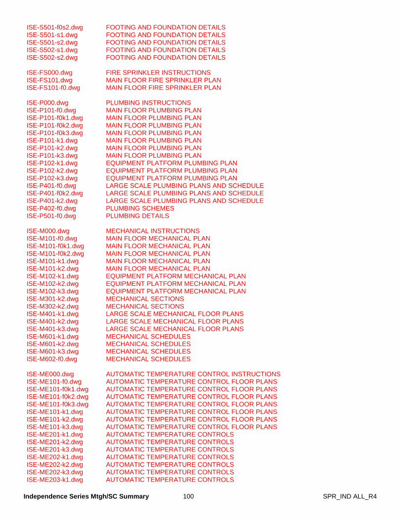
Independence Series Mtgh/SC Summary 100 SPR_IND ALL_R4
ISE-S501-f0s2.dwg FOOTING AND FOUNDATION DETAILS ISE-S501-s1.dwg FOOTING AND FOUNDATION DETAILS ISE-S501-s2.dwg FOOTING AND FOUNDATION DETAILS ISE-S502-s1.dwg FOOTING AND FOUNDATION DETAILS ISE-S502-s2.dwg FOOTING AND FOUNDATION DETAILS ISE-FS000.dwg FIRE SPRINKLER INSTRUCTIONS ISE-FS101.dwg MAIN FLOOR FIRE SPRINKLER PLAN ISE-FS101-f0.dwg MAIN FLOOR FIRE SPRINKLER PLAN ISE-P000.dwg PLUMBING INSTRUCTIONS ISE-P101-f0.dwg MAIN FLOOR PLUMBING PLAN ISE-P101-f0k1.dwg MAIN FLOOR PLUMBING PLAN ISE-P101-f0k2.dwg MAIN FLOOR PLUMBING PLAN ISE-P101-f0k3.dwg MAIN FLOOR PLUMBING PLAN ISE-P101-k1.dwg MAIN FLOOR PLUMBING PLAN ISE-P101-k2.dwg MAIN FLOOR PLUMBING PLAN ISE-P101-k3.dwg MAIN FLOOR PLUMBING PLAN ISE-P102-k1.dwg EQUIPMENT PLATFORM PLUMBING PLAN ISE-P102-k2.dwg EQUIPMENT PLATFORM PLUMBING PLAN ISE-P102-k3.dwg EQUIPMENT PLATFORM PLUMBING PLAN ISE-P401-f0.dwg LARGE SCALE PLUMBING PLANS AND SCHEDULE ISE-P401-f0k2.dwg LARGE SCALE PLUMBING PLANS AND SCHEDULE ISE-P401-k2.dwg LARGE SCALE PLUMBING PLANS AND SCHEDULE ISE-P402-f0.dwg PLUMBING SCHEMES ISE-P501-f0.dwg PLUMBING DETAILS ISE-M000.dwg MECHANICAL INSTRUCTIONS ISE-M101-f0.dwg MAIN FLOOR MECHANICAL PLAN ISE-M101-f0k1.dwg MAIN FLOOR MECHANICAL PLAN ISE-M101-f0k2.dwg MAIN FLOOR MECHANICAL PLAN ISE-M101-k1.dwg MAIN FLOOR MECHANICAL PLAN ISE-M101-k2.dwg MAIN FLOOR MECHANICAL PLAN ISE-M102-k1.dwg EQUIPMENT PLATFORM MECHANICAL PLAN ISE-M102-k2.dwg EQUIPMENT PLATFORM MECHANICAL PLAN ISE-M102-k3.dwg EQUIPMENT PLATFORM MECHANICAL PLAN ISE-M301-k2.dwg MECHANICAL SECTIONS ISE-M302-k2.dwg MECHANICAL SECTIONS ISE-M401-k1.dwg LARGE SCALE MECHANICAL FLOOR PLANS ISE-M401-k2.dwg LARGE SCALE MECHANICAL FLOOR PLANS ISE-M401-k3.dwg LARGE SCALE MECHANICAL FLOOR PLANS ISE-M601-k1.dwg MECHANICAL SCHEDULES ISE-M601-k2.dwg MECHANICAL SCHEDULES ISE-M601-k3.dwg MECHANICAL SCHEDULES ISE-M602-f0.dwg MECHANICAL SCHEDULES ISE-ME000.dwg AUTOMATIC TEMPERATURE CONTROL INSTRUCTIONS ISE-ME101-f0.dwg AUTOMATIC TEMPERATURE CONTROL FLOOR PLANS ISE-ME101-f0k1.dwg AUTOMATIC TEMPERATURE CONTROL FLOOR PLANS ISE-ME101-f0k2.dwg AUTOMATIC TEMPERATURE CONTROL FLOOR PLANS ISE-ME101-f0k3.dwg AUTOMATIC TEMPERATURE CONTROL FLOOR PLANS ISE-ME101-k1.dwg AUTOMATIC TEMPERATURE CONTROL FLOOR PLANS ISE-ME101-k2.dwg AUTOMATIC TEMPERATURE CONTROL FLOOR PLANS ISE-ME101-k3.dwg AUTOMATIC TEMPERATURE CONTROL FLOOR PLANS ISE-ME201-k1.dwg AUTOMATIC TEMPERATURE CONTROLS ISE-ME201-k2.dwg AUTOMATIC TEMPERATURE CONTROLS ISE-ME201-k3.dwg AUTOMATIC TEMPERATURE CONTROLS ISE-ME202-k1.dwg AUTOMATIC TEMPERATURE CONTROLS ISE-ME202-k2.dwg AUTOMATIC TEMPERATURE CONTROLS ISE-ME202-k3.dwg AUTOMATIC TEMPERATURE CONTROLS ISE-ME203-k1.dwg AUTOMATIC TEMPERATURE CONTROLS
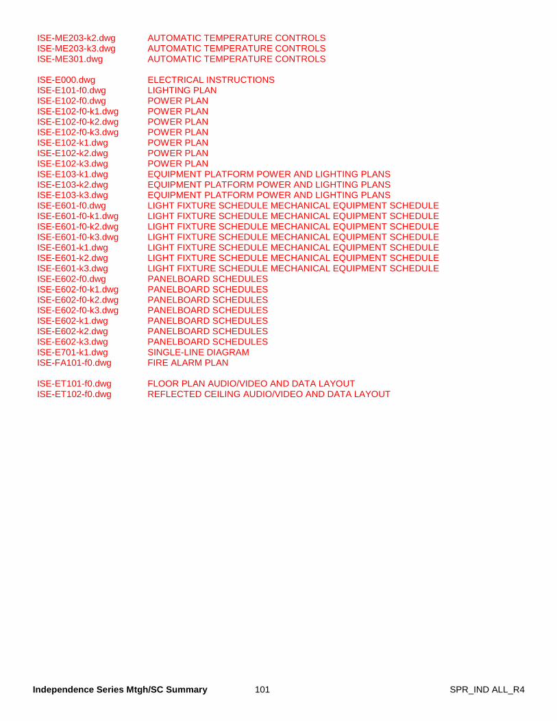
Independence Series Mtgh/SC Summary 101 SPR_IND ALL_R4
ISE-ME203-k2.dwg AUTOMATIC TEMPERATURE CONTROLS ISE-ME203-k3.dwg AUTOMATIC TEMPERATURE CONTROLS ISE-ME301.dwg AUTOMATIC TEMPERATURE CONTROLS ISE-E000.dwg ELECTRICAL INSTRUCTIONS ISE-E101-f0.dwg LIGHTING PLAN ISE-E102-f0.dwg POWER PLAN ISE-E102-f0-k1.dwg POWER PLAN ISE-E102-f0-k2.dwg POWER PLAN ISE-E102-f0-k3.dwg POWER PLAN ISE-E102-k1.dwg POWER PLAN ISE-E102-k2.dwg POWER PLAN ISE-E102-k3.dwg POWER PLAN ISE-E103-k1.dwg EQUIPMENT PLATFORM POWER AND LIGHTING PLANS ISE-E103-k2.dwg EQUIPMENT PLATFORM POWER AND LIGHTING PLANS ISE-E103-k3.dwg EQUIPMENT PLATFORM POWER AND LIGHTING PLANS ISE-E601-f0.dwg LIGHT FIXTURE SCHEDULE MECHANICAL EQUIPMENT SCHEDULE ISE-E601-f0-k1.dwg LIGHT FIXTURE SCHEDULE MECHANICAL EQUIPMENT SCHEDULE ISE-E601-f0-k2.dwg LIGHT FIXTURE SCHEDULE MECHANICAL EQUIPMENT SCHEDULE ISE-E601-f0-k3.dwg LIGHT FIXTURE SCHEDULE MECHANICAL EQUIPMENT SCHEDULE ISE-E601-k1.dwg LIGHT FIXTURE SCHEDULE MECHANICAL EQUIPMENT SCHEDULE ISE-E601-k2.dwg LIGHT FIXTURE SCHEDULE MECHANICAL EQUIPMENT SCHEDULE ISE-E601-k3.dwg LIGHT FIXTURE SCHEDULE MECHANICAL EQUIPMENT SCHEDULE ISE-E602-f0.dwg PANELBOARD SCHEDULES ISE-E602-f0-k1.dwg PANELBOARD SCHEDULES ISE-E602-f0-k2.dwg PANELBOARD SCHEDULES ISE-E602-f0-k3.dwg PANELBOARD SCHEDULES ISE-E602-k1.dwg PANELBOARD SCHEDULES ISE-E602-k2.dwg PANELBOARD SCHEDULES ISE-E602-k3.dwg PANELBOARD SCHEDULES ISE-E701-k1.dwg SINGLE-LINE DIAGRAM ISE-FA101-f0.dwg FIRE ALARM PLAN ISE-ET101-f0.dwg FLOOR PLAN AUDIO/VIDEO AND DATA LAYOUT ISE-ET102-f0.dwg REFLECTED CEILING AUDIO/VIDEO AND DATA LAYOUT