Embed Size (px)
Citation preview
2.01
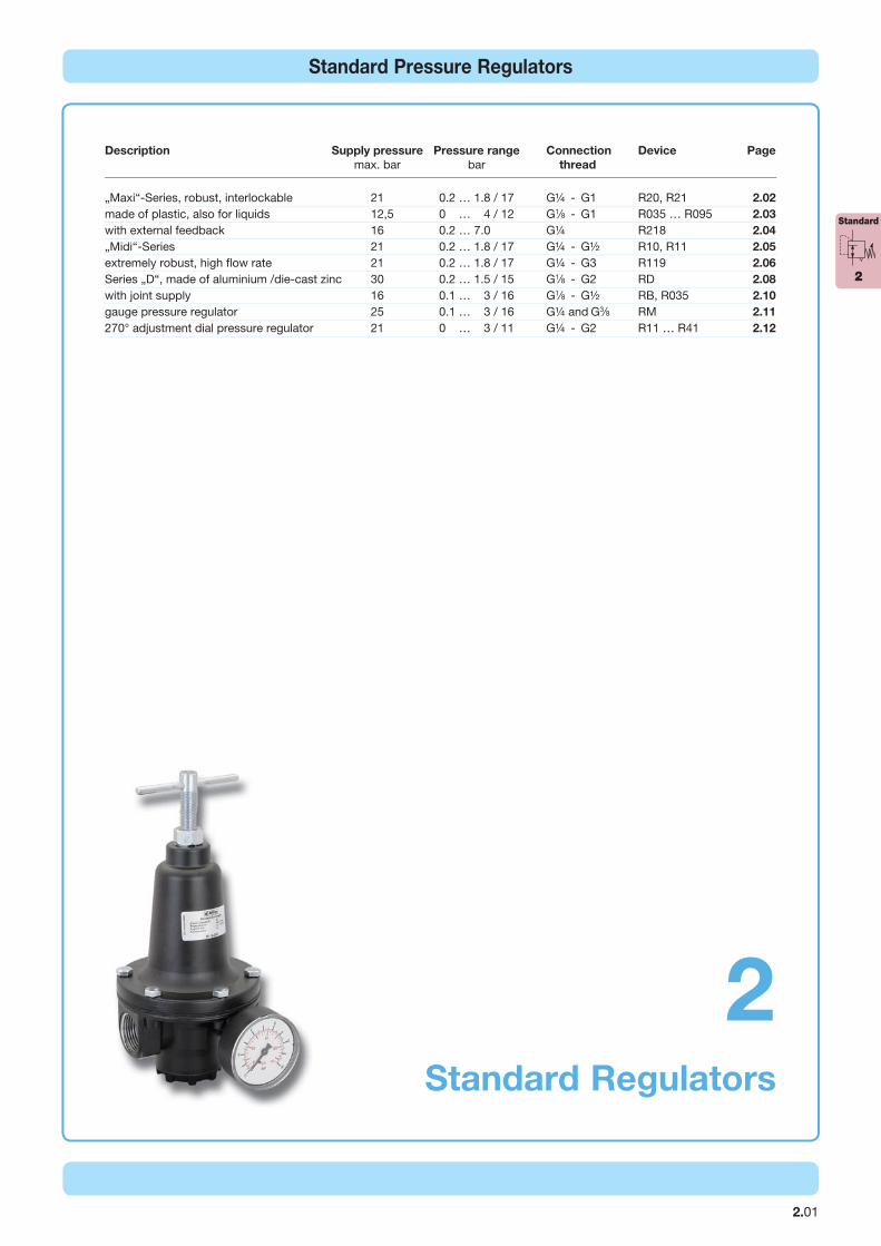
Standard Pressure Regulators
Standard Regulators
2
Description Supply pressure Pressure range Connection Device Page
max. bar bar thread
„Maxi“-Series, robust, interlockable 21 0.2 … 1.8 / 17 G¼ - G1 R20, R21 2.02
made of plastic, also for liquids 12,5 0 … 4 / 12 G1∕8 - G1 R035 … R095 2.03
with external feedback 16 0.2 … 7.0 G¼ R218 2.04
„Midi“-Series 21 0.2 … 1.8 / 17 G¼ - G½ R10, R11 2.05
extremely robust, high fl ow rate 21 0.2 … 1.8 / 17 G¼ - G3 R119 2.06
Series „D“, made of aluminium /die-cast zinc 30 0.2 … 1.5 / 15 G1∕8 - G2 RD 2.08
with joint supply 16 0.1 … 3 / 16 G1∕8 - G½ RB, R035 2.10
gauge pressure regulator 25 0.1 … 3 / 16 G¼ and G3∕8 RM 2.11
270° adjustment dial pressure regulator 21 0 … 3 / 11 G¼ - G2 R11 … R41 2.12
Standard
2
Dimensions Kv- Flow Connection Pressure Order Preis
A B C value rate thread range number
mm mm mm (m³/h) m³/h*1 l/min*1 G bar €
Produktgruppe
pressure gauge Ø 63 mm, 0 …*2 bar, G¼ up to 16 bar MA6302-. .*2 10,50 Ø 63 mm, 0 …25 bar, G¼ up to 25 bar MA6302-. .25 12,00 mounting bracket assembly at spring cage BW45-02 14,50 mounting nut made of plastic M45x1,5K 3,00 made of aluminium M45x1,5A 6,00 set of brackets made of steel MK20-0100 21,00
Order example:
R20-02AGauges: see chapter for measuring devices
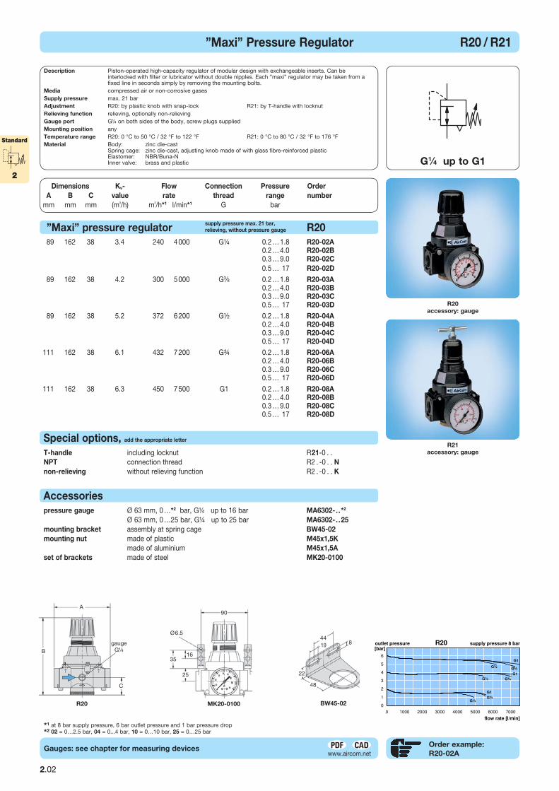
*1 at 8 bar supply pressure, 6 bar outlet pressure and 1 bar pressure drop*2 02 = 0…2.5 bar, 04 = 0...4 bar, 10 = 0…10 bar, 25 = 0…25 bar
A
R21
accessory: gauge
R20
accessory: gauge
T-handle including locknut R21-0 . . o. Mehrpr. NPT connection thread R2 . -0 . . N +10,00 non-relieving without relieving function R2 . -0 . . K + 2,50
Special options, add the appropriate letter
89 162 38 3.4 240 4 000 G¼ 0.2 … 1.8 R20-02A 170,00 0.2 … 4.0 R20-02B 170,00 0.3 … 9.0 R20-02C 170,00 0.5 … 17 R20-02D 170,00
89 162 38 4.2 300 5 000 G3∕8 0.2 … 1.8 R20-03A 170,00 0.2 … 4.0 R20-03B 170,00 0.3 … 9.0 R20-03C 170,00 0.5 … 17 R20-03D 170,00
89 162 38 5.2 372 6 200 G½ 0.2 … 1.8 R20-04A 170,00 0.2 … 4.0 R20-04B 170,00 0.3 … 9.0 R20-04C 170,00 0.5 … 17 R20-04D 170,00
111 162 38 6.1 432 7 200 G¾ 0.2 … 1.8 R20-06A 170,00 0.2 … 4.0 R20-06B 170,00 0.3 … 9.0 R20-06C 170,00 0.5 … 17 R20-06D 170,00
111 162 38 6.3 450 7 500 G1 0.2 … 1.8 R20-08A 170,00 0.2 … 4.0 R20-08B 170,00 0.3 … 9.0 R20-08C 170,00 0.5 … 17 R20-08D 170,00
”Maxi” pressure regulator R20
Ø6.5
90
25
gaugeG¼
35
A
C
B16
G1∕4 up to G1
”Maxi” Pressure Regulator R20 / R21
BBBBB
MK20-0100 BW45-02
44
48
819
22
Accessories
R20
2.02
Standard
2
Description Piston-operated high-capacity regulator of modular design with exchangeable inserts. Can be interlocked with filter or lubricator without double nipples. Each ”maxi” regulator may be taken from a fixed line in seconds simply by removing the mounting bolts.Media compressed air or non-corrosive gasesSupply pressure max. 21 bar Adjustment R20: by plastic knob with snap-lock R21: by T-handle with locknutRelieving function relieving, optionally non-relievingGauge port G¼ on both sides of the body, screw plugs suppliedMounting position anyTemperature range R20: 0 °C to 50 °C / 32 °F to 122 °F R21: 0 °C to 80 °C / 32 °F to 176 °FMaterial Body: zinc die-cast Spring cage: zinc die-cast, adjusting knob made of with glass fibre-reinforced plastic Elastomer: NBR/Buna-N Inner valve: brass and plastic
supply pressure max. 21 bar,
relieving, without pressure gauge
2.03
Produktgruppe
Dimensions Kv- Flow Connection Pressure Order Preis
A B C value rate thread range number
mm mm mm (m³/h) m³/h*1 l/min*1 G bar €
Versorgungsdruck max. 13 bar
Versorgungsdruck max. 13 bar
000 0
B
Accessories and mounting brackets: see chapter for FRL service units
Gauges: see chapter for measuring devices
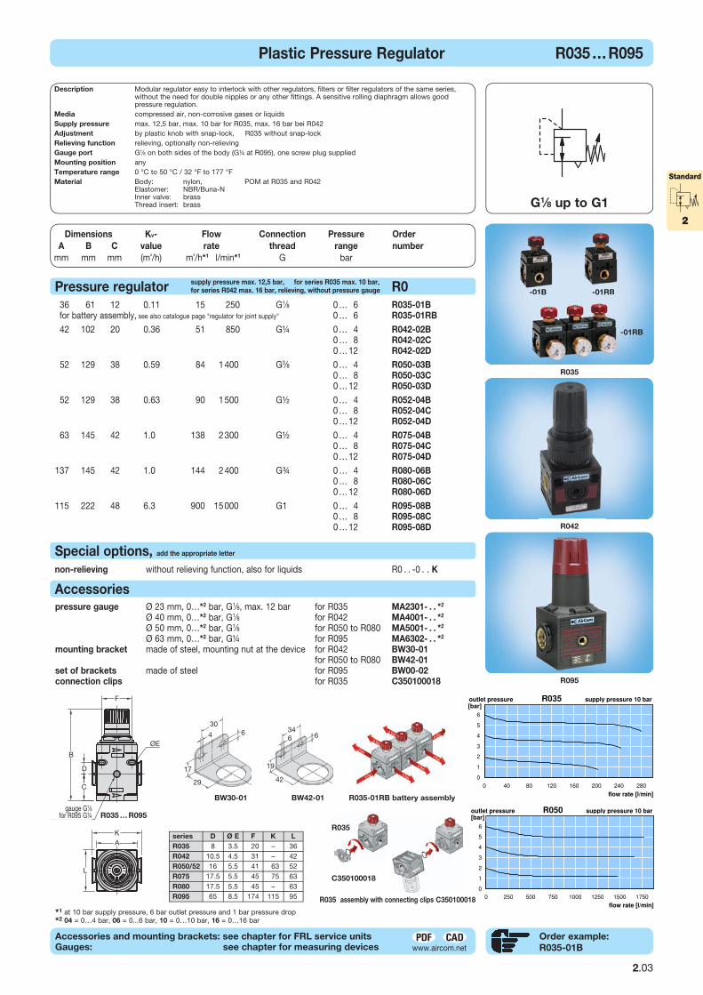
*1 at 10 bar supply pressure, 6 bar outlet pressure and 1 bar pressure drop*2 04 = 0…4 bar, 06 = 0...6 bar, 10 = 0…10 bar, 16 = 0…16 bar
Special options, add the appropriate letter
pressure gauge Ø 23 mm, 0…*2 bar, G1∕8, max. 12 bar for R035 MA2301- . . *2 11,00 Ø 40 mm, 0…*2 bar, G1∕8 for R042 MA4001- . . *2 9,50 Ø 50 mm, 0…*2 bar, G1∕8 for R050 to R080 MA5001- . . *2 9,50 Ø 63 mm, 0…*2 bar, G¼ for R095 MA6302- . . *2 10,50 mounting bracket made of steel, mounting nut at the device for R042 BW30-01 6,00 for R050 to R080 BW42-01 9,50 set of brackets made of steel for R095 BW00-02 24,00 connection clips for R035 C350100018 2,50
non-relieving without relieving function, also for liquids R0 . . -0 . . K +2,50
Pressure regulator R0
36 61 12 0.11 15 250 G1∕8 0 … 6 R035-01B 20,50 for battery assembly, see also catalogue page "regulator for joint supply" 0 … 6 R035-01RB 20,50
42 102 20 0.36 51 850 G¼ 0 … 4 R042-02B 26,00 0 … 8 R042-02C 26,00 0 … 12 R042-02D 26,00
52 129 38 0.59 84 1 400 G3∕8 0 … 4 R050-03B 38,00 0 … 8 R050-03C 38,00 0 … 12 R050-03D 38,00
52 129 38 0.63 90 1 500 G½ 0 … 4 R052-04B 41,00 0 … 8 R052-04C 41,00 0 … 12 R052-04D 41,00
63 145 42 1.01 138 2 300 G½ 0 … 4 R075-04B 51,00 0 … 8 R075-04C 51,00 0 … 12 R075-04D 51,00
137 145 42 1.01 144 2 400 G¾ 0 … 4 R080-06B 76,00 0 … 8 R080-06C 76,00 0 … 12 R080-06D 76,00
115 222 48 6.31 900 15 000 G1 0 … 4 R095-08B 190,00 0 … 8 R095-08C 190,00 0 … 12 R095-08D 190,00
Order example:
R035-01B
R035
-01B -01RB
R042
R095
G1∕8 up to G1
Plastic Pressure Regulator R035 … R095
--01B -01RBB
R035-01RB battery assembly
R035
R035 assembly with connecting clips C350100018
C350100018
30
17
29
4 6
BW30-01
34
19
42
6 6
BW42-01
Accessories
series D Ø E F K L
R035 8 3.5 20 – 36 R042 10.5 4.5 31 – 42 R050/52 16 5.5 41 63 52 R075 17.5 5.5 45 75 63 R080 17.5 5.5 45 – 63 R095 65 8.5 174 115 95
-01RB
Standard
2
R035 … R095
Description Modular regulator easy to interlock with other regulators, filters or filter regulators of the same series, without the need for double nipples or any other fittings. A sensitive rolling diaphragm allows good pressure regulation.
Media compressed air, non-corrosive gases or liquidsSupply pressure max. 12,5 bar, max. 10 bar for R035, max. 16 bar bei R042Adjustment by plastic knob with snap-lock, R035 without snap-lockRelieving function relieving, optionally non-relievingGauge port G1∕8 on both sides of the body (G¼ at R095), one screw plug suppliedMounting position anyTemperature range 0 °C to 50 °C / 32 °F to 177 °FMaterial Body: nylon, POM at R035 and R042 Elastomer: NBR/Buna-N Inner valve: brass Thread insert: brass
supply pressure max. 12,5 bar, for series R035 max. 10 bar,
for series R042 max. 16 bar, relieving, without pressure gauge
gauge G1∕8for R095 G¼
Standard
2
Produktgruppe
Dimensions Kv- Flow Connection Pressure Order Preis
A B C value rate thread range number
mm mm mm (m³/h) m³/h*1 l/min*1 G bar €
Order exampel:
R218-02C
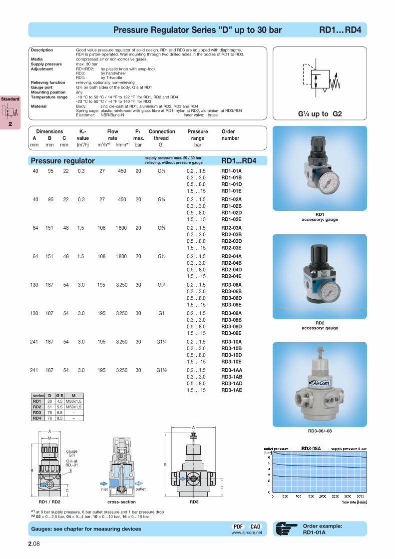
*1 at 8 bar supply pressure, 6 bar outlet pressure and 1 bar pressure drop
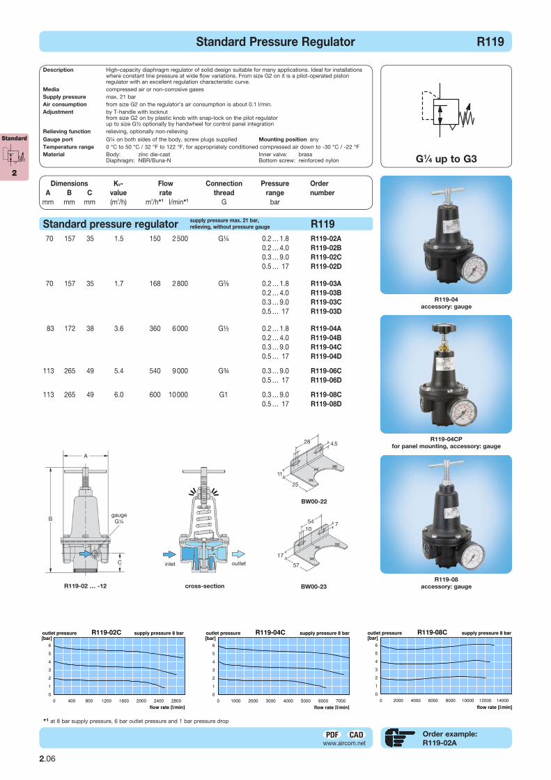
R218
Regulator with external feedback R218
82 154 19 0,3 25 420 G¼ 0.2 … 7.0 R218-02C 152,00
pressure gauge Ø 63 mm, 0 …10 bar, G¼ MA6302-10 10,50 mounting bracket made of steel BW00-36 10,00 mounting nut made of brass M20x1,5M 5,00
Description Diaphragm pressure regulator in small design for "feedback systems" in conjunction with volume flow boosters. Due to the external feedback, regulation is significantly improved and the flow rate increased.
Media compressed air and non-corrosive gases
Supply pressure max. 16 bar Air consumption approx. 3 bis 6 l/min
Adjustment by handwheel with snap-lock, for panel mounting
External Feedback should be installed at the outlet of the booster, e.g. at the gauge port, or at the outlet pipe. This will measure the pressure drop at the output of the booster and the pilot pressure will be readjusted.
Relieving function relieving
Gauge port G¼ on both sides of the body, screw plugs supplied Feedback connection G¼
Temperature range 0 °C to 60 °C / 32 °F to 140 °F Mounting position any
Material Body: zinc die-casting Spring cage: zinc die-casting Elastomer: FKM
D
Pressure Regulator with External Feedback R218
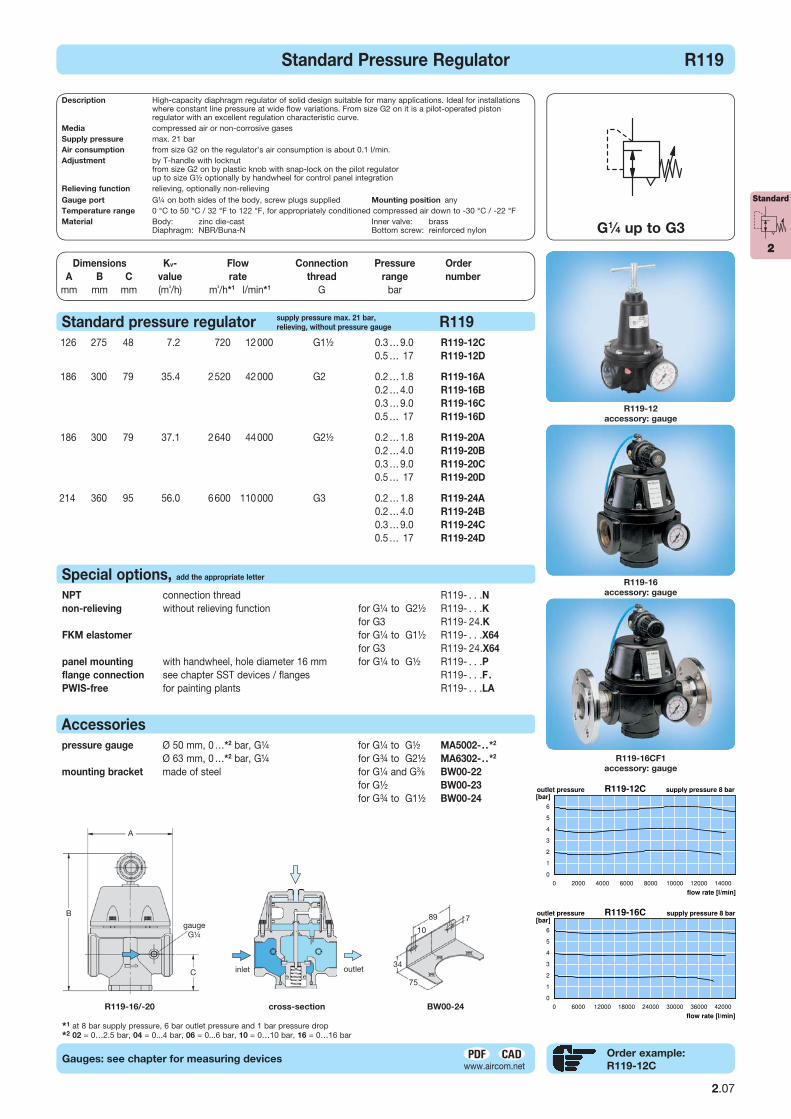
Example: combination with booster
supply pressure max. 16 bar,
relieving, with air consumption
Accessories
BW00-36
58
18
45
Ø9
pilot air
feedback signalmain flow P1
P2
P1
G¼ , max. 16 bar
420 l/min
outletinlet
panel cut-out
20
2.04
cross-section
feedbacksignal
R218

Standard
2 Dimensions Kv- Flow Connection Pressure Order Preis
A B C value rate thread range number
mm mm mm (m³/h) m³/h*1 l/min*1 G bar €
Produktgruppe
AA
B B
C C
R11R10
gaugeG¼ gauge
G¼
A
Order example:
R10-02AGauges: see chapter for measuring devices
*1 at 8 bar supply pressure, 6 bar outlet pressure and 1 bar pressure drop*2 02 = 0…2.5 bar, 04 = 0...4 bar, 10 = 0…10 bar, 25 = 0…25 bar
”Midi”pressure regulator R10
G1∕4 up to G½
”Midi” Pressure Regulator R10 / R11
60 124 35 1.8 132 2 200 G¼ 0.2 … 1.8 R10-02A 93,00
0.2 … 4.0 R10-02B 93,00
0.3 … 9.0 R10-02C 93,00
0.5 … 17 R10-02D 93,00
60 124 35 1.9 138 2 300 G3∕8 0.2 … 1.8 R10-03A 93,00
0.2 … 4.0 R10-03B 93,00
0.3 … 9.0 R10-03C 93,00
0.5 … 17 R10-03D 93,00
60 124 35 2.0 144 2 400 G½ 0.2 … 1.8 R10-04A 93,00
0.2 … 4.0 R10-04B 93,00
0.3 … 9.0 R10-04C 93,00
0.5 … 17 R10-04D 93,00
pressure gauge Ø 50 mm, 0 …*2 bar, G1∕4 up to 10 bar MA5002-. .*2 9,50 Ø 50 mm, 0 …25 bar, G1∕4 up to 25 bar MA5002-. .25 12,00 mounting bracket made of steel BW45-01 11,00 mounting nut made of plastic M45x1,5K 3,00 made of aluminium M45x1,5A 6,00
T-handle including locknut R11-0 . . o. Mehrpr. NPT connection thread R1 . -0 . . N +10,00 non-relieving without relieving function R1 . -0 . . K + 2,50 FKM elastomer inner parts made of brass R1 . -0 . . X64 +48,00 inner parts made of stainless steel R1 . -0 . . X08 +170,00
Special options, add the appropriate letter
R11
with T-handle, accessory: gauge
R10
with knob, accesssory: gauge
cross-section
4117
36
20
7
BW45-01
supply pressure max. 21 bar,
relieving, without pressure gauge
inlet outlet
Accessories
2.05
Description All-purpose, high-performance, diaphragm regulator with high flow.
Media compressed air or non-corrosive gases
Supply pressure max. 21 bar
Adjustment R10: by plastic knob with snap-lock R11: by T-handle with locknut
Relieving function relieving, optionally non-relieving
Gauge port G¼ on both sides of the body, screw plug supplied
Mounting position any
Temperature range R10: 0 °C to 50 °C / 32 °F to 122 °F R11: 0 °C to 70 °C / 32 °F to 158 °F, for appropriately conditioned compr. air down to -30 °C / -22 °F
Material Body: zinc die-cast Spring cage: glass fibre-reinforced plastic at R10, zinc die-cast at R11 Elastomer: NBR/Buna-N, optionally FKM Inner valve: brass, optionally stainless steel
Standard
2 Dimensions Kv- Flow Connection Pressure Order Preis
A B C value rate thread range number
mm mm mm (m³/h) m³/h*1 l/min*1 G bar €
Produktgruppe
gaugeG¼ B
R119-04
accessory: gauge
R119-04CP
for panel mounting, accessory: gauge
R119-08
accessory: gaugeR119-02 … -12
A
*1 at 8 bar supply pressure, 6 bar outlet pressure and 1 bar pressure drop
Order example:
R119-02A
Standard pressure regulator R119
70 157 35 1.5 150 2 500 G¼ 0.2 … 1.8 R119-02A 85,00 0.2 … 4.0 R119-02B 85,00 0.3 … 9.0 R119-02C 85,00 0.5 … 17 R119-02D 85,00
70 157 35 1.7 168
2 800 G3∕8 0.2 … 1.8 R119-03A 85,00 0.2 … 4.0 R119-03B 85,00 0.3 … 9.0 R119-03C 85,00 0.5 … 17 R119-03D 85,00
83 172 38 3.6 360
6 000 G½ 0.2 … 1.8 R119-04A 100,00 0.2 … 4.0 R119-04B 100,00 0.3 … 9.0 R119-04C 100,00 0.5 … 17 R119-04D 100,00
113 265 49 5.4 540
9 000 G¾ 0.3 … 9.0 R119-06C 178,00 0.5 … 17 R119-06D 178,00
113 265 49 6.0 600 10 000 G1 0.3 … 9.0 R119-08C 178,00 0.5 … 17 R119-08D 178,00
G1∕4 up to G3
Standard Pressure Regulator R119
C
A
cross-section
4.5
25
11
28
BW00-22
BW00-23
54
17
107
57inlet outlet
supply pressure max. 21 bar,
relieving, without pressure gauge
2.06
Description High-capacity diaphragm regulator of solid design suitable for many applications. Ideal for installations where constant line pressure at wide flow variations. From size G2 on it is a pilot-operated piston regulator with an excellent regulation characteristic curve.
Media compressed air or non-corrosive gasesSupply pressure max. 21 bar Air consumption from size G2 on the regulator’s air consumption is about 0.1 l/min.Adjustment by T-handle with locknut from size G2 on by plastic knob with snap-lock on the pilot regulator up to size G½ optionally by handwheel for control panel integrationRelieving function relieving, optionally non-relievingGauge port G¼ on both sides of the body, screw plugs supplied Mounting position anyTemperature range 0 °C to 50 °C / 32 °F to 122 °F, for appropriately conditioned compressed air down to -30 °C / -22 °FMaterial Body: zinc die-cast Inner valve: brass Diaphragm: NBR/Buna-N Bottom screw: reinforced nylon
Standard
2
Produktgruppe
A
R119-12
accessory: gauge
R119-16
accessory: gauge
R119-16CF1
accessory: gauge
Order example:
R119-12CGauges: see chapter for measuring devices
NPT connection thread R119- . . .N +10,00 non-relieving without relieving function for G¼ to G2½ R119- . . .K + 2,50 for G3 R119- 24.K + 5,00 FKM elastomer for G¼ to G1½ R119- . . .X64 +100,00 for G3 R119- 24.X64 +560,00 panel mounting with handwheel, hole diameter 16 mm for G¼ to G½ R119- . . .P +25,00 flange connection see chapter SST devices / flanges R119- . . .F. s. Kap.15 PWIS-free for painting plants R119- . . .LA auf Anfr.
Special options, add the appropriate letter
Standard pressure regulator R119
126 275 48 7.2 720 12 000 G1½ 0.3 … 9.0 R119-12C 288,00 0.5 … 17 R119-12D 288,00
186 300 79 35.4 2 520 42 000 G2 0.2 … 1.8 R119-16A 1100,00 0.2 … 4.0 R119-16B 1100,00 0.3 … 9.0 R119-16C 1100,00 0.5 … 17 R119-16D 1100,00
186 300 79 37.1 2 640 44 000 G2½ 0.2 … 1.8 R119-20A 1100,00 0.2 … 4.0 R119-20B 1100,00 0.3 … 9.0 R119-20C 1100,00 0.5 … 17 R119-20D 1100,00
214 360 95 56.0 6 600 110 000 G3 0.2 … 1.8 R119-24A 2350,00 0.2 … 4.0 R119-24B 2350,00 0.3 … 9.0 R119-24C 2350,00 0.5 … 17 R119-24D 2350,00
A
C
B
*1 at 8 bar supply pressure, 6 bar outlet pressure and 1 bar pressure drop*2 02 = 0…2.5 bar, 04 = 0...4 bar, 06 = 0...6 bar, 10 = 0…10 bar, 16 = 0…16 bar
Standard Pressure Regulator R119
R119-16/-20 cross-section
G1∕4 up to G3
BW00-24
89
10
34
7
75
pressure gauge Ø 50 mm, 0 …*2 bar, G¼ for G¼ to G½ MA5002-. .*2 9,50 Ø 63 mm, 0 …*2 bar, G¼ for G¾ to G2½ MA6302-. .*2 10,50 mounting bracket made of steel for G¼ and G3∕8 BW00-22 13,50 for G½ BW00-23 13,50 for G¾ to G1½ BW00-24 30,00
Accessories
inlet outlet
gaugeG¼
2.07
Description High-capacity diaphragm regulator of solid design suitable for many applications. Ideal for installations where constant line pressure at wide flow variations. From size G2 on it is a pilot-operated piston regulator with an excellent regulation characteristic curve.
Media compressed air or non-corrosive gasesSupply pressure max. 21 bar Air consumption from size G2 on the regulator’s air consumption is about 0.1 l/min.Adjustment by T-handle with locknut from size G2 on by plastic knob with snap-lock on the pilot regulator up to size G½ optionally by handwheel for control panel integrationRelieving function relieving, optionally non-relievingGauge port G¼ on both sides of the body, screw plugs supplied Mounting position anyTemperature range 0 °C to 50 °C / 32 °F to 122 °F, for appropriately conditioned compressed air down to -30 °C / -22 °FMaterial Body: zinc die-cast Inner valve: brass Diaphragm: NBR/Buna-N Bottom screw: reinforced nylon
Dimensions Kv- Flow Connection Pressure Order Preis
A B C value rate thread range number
mm mm mm (m³/h) m³/h*1 l/min*1 G bar €
A
supply pressure max. 21 bar,
relieving, without pressure gauge
Standard
2
Produktgruppe
Order example:
RD1-01A
Dimensions Kv- Flow P1 Connection Pressure Order Preis
A B C value rate max. thread range number
mm mm mm (m³/h) m³/h*1 l/min*1 bar G bar €
A
RD1
accessory: gauge
RD2
accessory: gauge
RD3-06/-08
G1∕4 up to G2
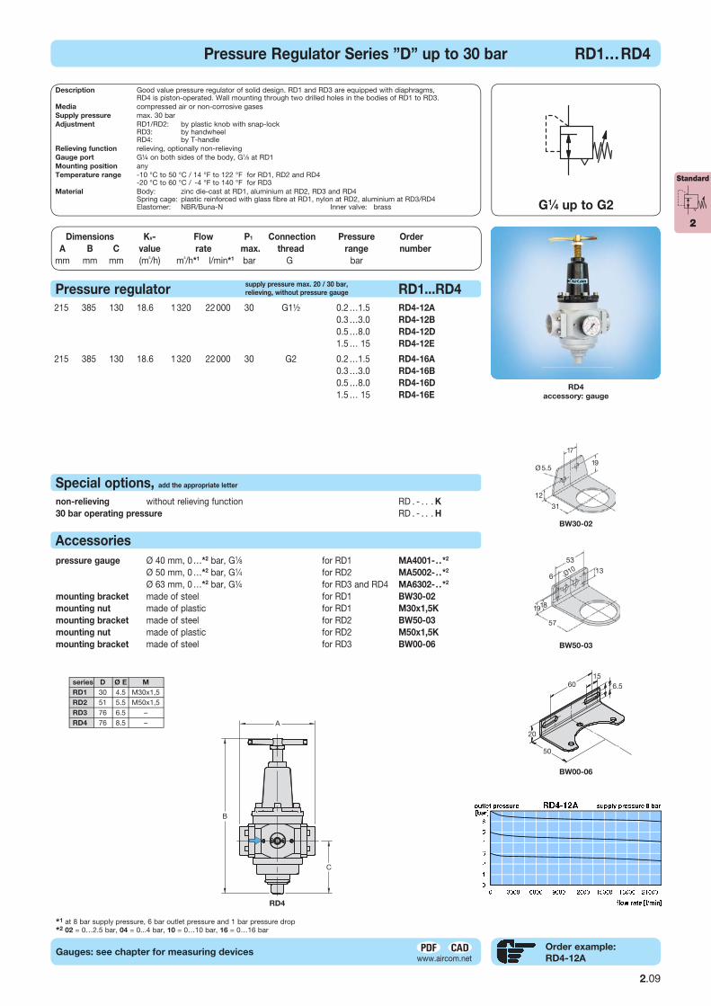
Pressure Regulator Series ”D” up to 30 bar RD1…RD4
Gauges: see chapter for measuring devices
*1 at 8 bar supply pressure, 6 bar outlet pressure and 1 bar pressure drop*2 02 = 0…2.5 bar, 04 = 0...4 bar, 10 = 0…10 bar, 16 = 0…16 bar
2.08
Pressure regulator RD1...RD4
40 95 22 0.3 27 450 20 G1∕8 0.2 …1.5 RD1-01A 29,00 0.3 …3.0 RD1-01B 29,00 0.5 …8.0 RD1-01D 29,00 1.5 … 15 RD1-01E 29,00
40 95 22 0.3 27 450 20 G¼ 0.2 …1.5 RD1-02A 29,00 0.3 …3.0 RD1-02B 29,00 0.5 …8.0 RD1-02D 29,00 1.5 … 15 RD1-02E 29,00
64 151 48 1.5 108 1 800 20 G3∕8 0.2 …1.5 RD2-03A 75,00 0.3 …3.0 RD2-03B 75,00 0.5 …8.0 RD2-03D 75,00 1.5 … 15 RD2-03E 75,00
64 151 48 1.5 108 1 800 20 G½ 0.2 …1.5 RD2-04A 75,00 0.3 …3.0 RD2-04B 75,00 0.5 …8.0 RD2-04D 75,00 1.5 … 15 RD2-04E 75,00
130 187 54 3.0 195 3 250 30 G¾ 0.2 …1.5 RD3-06A 430,00 0.3 …3.0 RD3-06B 430,00 0.5 …8.0 RD3-06D 430,00 1.5 … 15 RD3-06E 430,00
130 187 54 3.0 195 3 250 30 G1 0.2 …1.5 RD3-08A 430,00 0.3 …3.0 RD3-08B 430,00 0.5 …8.0 RD3-08D 430,00 1.5 … 15 RD3-08E 430,00
241 187 54 3.0 195 3 250 30 G1¼ 0.2 …1.5 RD3-10A 650,00 0.3 …3.0 RD3-10B 650,00 0.5 …8.0 RD3-10D 650,00 1.5 … 15 RD3-10E 650,00
241 187 54 3.0 195 3 250 30 G1½ 0.2 …1.5 RD3-1AA 650,00 0.3 …3.0 RD3-1AB 650,00 0.5 …8.0 RD3-1AD 650,00 1.5 … 15 RD3-1AE 650,00
supply pressure max. 20 / 30 bar,
relieving, without pressure gauge
RD1 / RD2
gaugeG1∕4
G1⁄8 at RD.-01
RD3
series D Ø E M
RD1 30 4.5 M30x1,5 RD2 51 5.5 M50x1,5 RD3 76 6.5 – RD4 76 8.5 –
cross-section
inlet outlet
Description Good value pressure regulator of solid design. RD1 and RD3 are equipped with diaphragms, RD4 is piston-operated. Wall mounting through two drilled holes in the bodies of RD1 to RD3.Media compressed air or non-corrosive gasesSupply pressure max. 30 barAdjustment RD1/RD2: by plastic knob with snap-lock RD3: by handwheel RD4: by T-handleRelieving function relieving, optionally non-relievingGauge port G¼ on both sides of the body, G1∕8 at RD1 Mounting position anyTemperature range -10 °C to 50 °C / 14 °F to 122 °F for RD1, RD2 and RD4 -20 °C to 60 °C / -4 °F to 140 °F for RD3Material Body: zinc die-cast at RD1, aluminium at RD2, RD3 and RD4 Spring cage: plastic reinforced with glass fibre at RD1, nylon at RD2, aluminium at RD3/RD4 Elastomer: NBR/Buna-N Inner valve: brass
Standard
2
Produktgruppe
Order example:
RD4-12AGauges: see chapter for measuring devices
Pressure Regulator Series ”D” up to 30 bar RD1…RD4
G1∕4 up to G2
*1 at 8 bar supply pressure, 6 bar outlet pressure and 1 bar pressure drop*2 02 = 0…2.5 bar, 04 = 0...4 bar, 10 = 0…10 bar, 16 = 0…16 bar
RD4
accessory: gauge
2.09
19
31
12
Ø 5.5
17
BW30-02
non-relieving without relieving function RD . - . . . K +5% 30 bar operating pressure RD . - . . . H +100%
Special options, add the appropriate letter
Accessories
pressure gauge Ø 40 mm, 0 …*2 bar, G1∕8 for RD1 MA4001-. .*2 9,50 Ø 50 mm, 0 …*2 bar, G1∕4 for RD2 MA5002-. .*2 9,50 Ø 63 mm, 0 …*2 bar, G¼ for RD3 and RD4 MA6302-. .*2 10,50 mounting bracket made of steel for RD1 BW30-02 9,00 mounting nut made of plastic for RD1 M30x1,5K 2,00 mounting bracket made of steel for RD2 BW50-03 12,00 mounting nut made of plastic for RD2 M50x1,5K 3,00 mounting bracket made of steel for RD3 BW00-06 16,00
Pressure regulator RD1...RD4
215 385 130 18.6 1 320 22 000 30 G1½ 0.2 …1.5 RD4-12A 875,00 0.3 …3.0 RD4-12B 875,00 0.5 …8.0 RD4-12D 875,00 1.5 … 15 RD4-12E 875,00
215 385 130 18.6 1 320 22 000 30 G2 0.2 …1.5 RD4-16A 875,00 0.3 …3.0 RD4-16B 875,00 0.5 …8.0 RD4-16D 875,00 1.5 … 15 RD4-16E 875,00
RD4
BW00-06
series D Ø E M
RD1 30 4.5 M30x1,5 RD2 51 5.5 M50x1,5 RD3 76 6.5 – RD4 76 8.5 –
BW50-03
57
18
Ø106
53
13
19
6015
6.5
50
20
Description Good value pressure regulator of solid design. RD1 and RD3 are equipped with diaphragms, RD4 is piston-operated. Wall mounting through two drilled holes in the bodies of RD1 to RD3.Media compressed air or non-corrosive gasesSupply pressure max. 30 barAdjustment RD1/RD2: by plastic knob with snap-lock RD3: by handwheel RD4: by T-handleRelieving function relieving, optionally non-relievingGauge port G¼ on both sides of the body, G1∕8 at RD1 Mounting position anyTemperature range -10 °C to 50 °C / 14 °F to 122 °F for RD1, RD2 and RD4 -20 °C to 60 °C / -4 °F to 140 °F for RD3Material Body: zinc die-cast at RD1, aluminium at RD2, RD3 and RD4 Spring cage: plastic reinforced with glass fibre at RD1, nylon at RD2, aluminium at RD3/RD4 Elastomer: NBR/Buna-N Inner valve: brass
Dimensions Kv- Flow P1 Connection Pressure Order Preis
A B C value rate max. thread range number
mm mm mm (m³/h) m³/h*1 l/min*1 bar G bar €
A
supply pressure max. 20 / 30 bar,
relieving, without pressure gauge
2.10
Dimensions Kv- Flow Connection Pressure Order Preis
A B C splitting value rate thread range number
mm mm mm mm (m³/h) m³/h*1 l/min*1 G bar €
B
Order example:
R035-01RB
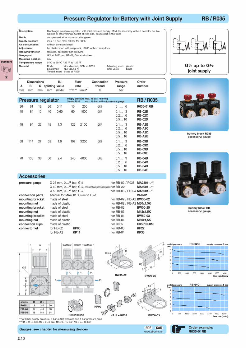
battery block RB
accessory: gauge
battery block R035
accessory: gauge
*1 at 8 bar supply pressure, 6 bar outlet pressure and 1 bar pressure drop*2 04 = 0…4 bar, 06 = 0...6 bar, 10 = 0…10 bar, 16 = 0…16 bar
pressure gauge Ø 23 mm, 0 …*2 bar, G1∕8 for RB-02 / R035 MA2301-..*2 11,00 Ø 40 mm, 0 …*2 bar, G1∕4, connection parts required for RB-A2 MA4001-..*2 9,50 Ø 50 mm, 0 …*2 bar, G1∕4 for RB-03 / RB-04 MA5001-..*2 9,50 connection parts adapter for MA4001, G1∕4m to G1∕8f VI-0201 2,00 mounting bracket made of steel for RB-02 / RB-A2 BW30-02 9,00 mounting nut made of plastic for RB-02 / RB-A2 M30x1,5K 2,00 mounting bracket made of steel for RB-03 BW00-25 9,00 mounting nut made of plastic for RB-03 M42x1,5K 3,00 mounting bracket made of steel for RB-04 BW50-03 12,00 mounting nut made of plastic for RB-04 M50x1,5K 3,00 connection clips made of plastic for R035 C350100018 2,50 connector kit for RB-02 KP00 2,50 for RB-03 KP22 2,50 for RB-A2 KP11 2,50 for RB-04 KP33 2,50
Accessories
36 61 12 36 0.11 15 250 G1∕8 0,1 … 6 R035-01RB 20,50
40 84 12 40 0.60 60 1 000 G¼ 0.1 … 3 RB-02B 42,00 0.2 … 6 RB-02C 42,00 0.5 … 10 RB-02D 42,00
48 94 22 45 1.3 126 2 100 G¼ 0.1 … 3 RB-A2B 44,00 0.2 … 6 RB-A2C 44,00 0.5 … 10 RB-A2D 44,00 0.5 … 16 RB-A2E 44,00
58 114 27 55 1.9 192 3 200 G3∕8 0.1 … 3 RB-03B 52,00 0.2 … 6 RB-03C 52,00 0.5 … 10 RB-03D 52,00 0.5 … 16 RB-03E 52,00
70 133 36 66 2.4 240 4 000 G½ 0.1 … 3 RB-04B 68,00 0.2 … 6 RB-04C 68,00 0.5 … 10 RB-04D 68,00 0.5 … 16 RB-04E 68,00
Pressure regulator RB / R035
G1∕8 up to G½
joint supply
Pressure Regulator for Battery with Joint Supply RB / R035
series D Ø E F
R035 8 3.5 20 RB-A2 12 4.4 36 RB-04 18 5.5 54
KP00
KP11 – KP33C350100018
C
A
F
B
D
ØE
partition partition partition
P2 P3 P4
P1 P1
BW30-02
19
31
12
Ø 5.5
17
BW50-03
57
18
Ø106
53
13
19
47
27
385
8
12.5
BW00-25
supply pressure max. 16 bar, relieving
Series R035 max. 10 bar, without pressure gauge
Gauges: see chapter for measuring devices
Standard
2
Description Diaphragm pressure regulator, with joint pressure supply. Modular assembly without need for double nipples or other fittings. Outlet at rear side, gauge port in the front.
Media compressed air or non-corrosive gasesSupply pressure max. 16 bar, max. 10 bar for R035Air consumption without constant bleedAdjustment by plastic knob with snap-lock, R035 without snap-lockRelieving function relieving, optionally non-relievingGauge port G1∕8 at R035 and RB-02, G¼ at all othersMounting position anyTemperature range 0 °C to 50 °C / 32 °F to 122 °FMaterial Body: zinc die-cast, POM at R035 Adjusting knob: plastic Elastomer: NBR/Buna-N Inner valve: brass Thread insert: brass at R035
2.11
Dimensions Kv- Flow Connection Pressure Order Preis
A B C value rate thread range number
mm mm mm (m³/h) m³/h*1 l/min*1 G bar €
C
Pressure regulator, P1 max. 16 bar RM1
Pressure regulator, P1 max. 25 bar RM2
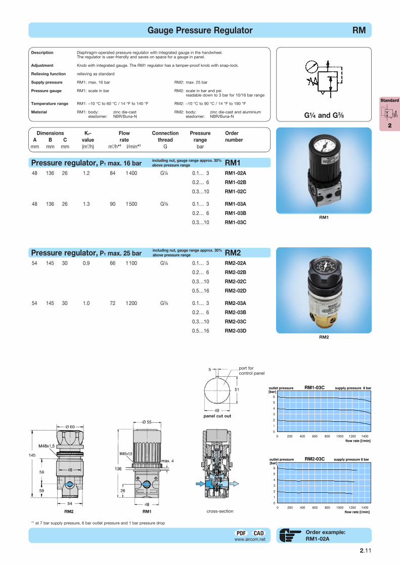
RM2
48 136 26 1.2 84 1 400 G¼ 0.1… 3 RM1-02A 88,00
0.2… 6 RM1-02B 88,00
0.3…10 RM1-02C 88,00
48 136 26 1.3 90 1 500 G3∕8 0.1… 3 RM1-03A 88,00
0.2… 6 RM1-03B 88,00
0.3…10 RM1-03C 88,00
54 145 30 0.9 66 1 100 G¼ 0.1… 3 RM2-02A 165,00
0.2… 6 RM2-02B 165,00
0.3…10 RM2-02C 165,00
0.5…16 RM2-02D 165,00
54 145 30 1.0 72 1 200 G3∕8 0.1… 3 RM2-03A 165,00
0.2… 6 RM2-03B 165,00
0.3…10 RM2-03C 165,00
0.5…16 RM2-03D 165,00
including nut, gauge range approx. 30%
above pressure range
G¼ and G3∕8
Gauge Pressure Regulator RM
Order example:
RM1-02A
RM1
*1 at 7 bar supply pressure, 6 bar outlet pressure and 1 bar pressure drop Produktgruppe
Description Diaphragm-operated pressure regulator with integrated gauge in the handwheel. The regulator is user-friendly and saves on space for a gauge in panel.
Adjustment Knob with integrated gauge. The RM1 regulator has a tamper-proof knob with snap-lock.
Relieving function relieving as standard
Supply pressure RM1: max. 16 bar RM2: max. 25 bar
Pressure gauge RM1: scale in bar RM2: scale in bar and psi readable down to 3 bar for 10/16 bar range
Temperature range RM1: –10 °C to 60 °C / 14 °F to 140 °F RM2: –10 °C to 90 °C / 14 °F to 190 °F
Material RM1: body: zinc die-cast RM2: body: zinc die-cast and aluminium elastomer: NBR/Buna-N elastomer: NBR/Buna-N
including nut, gauge range approx. 30%
above pressure range
panel cut out
port for control panel
cross-section
Standard
2
Dimensions Kv- Flow Connection Pressure Order Preis
A B C value rate thread range number
mm mm mm (m³/h) m³/h*1 l/min*1 G bar €
B
Produktgruppe
Order example:
R11-C2-LGauges: see chapter for measuring devices
Adjustment dial regulator R11…R41
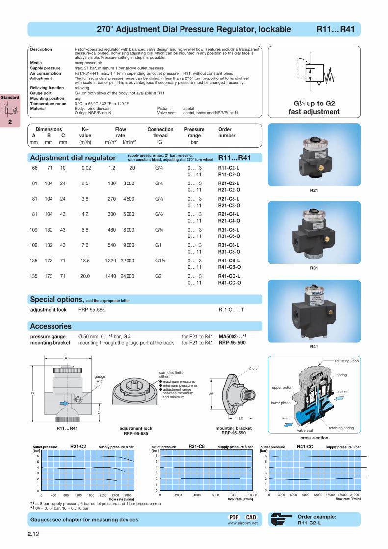
R21
R31
R41
cross-section
66 71 10 0.02 1.2 20 G¼ 0 … 3 R11-C2-L 150,00 0 … 11 R11-C2-O 150,00
81 104 24 2.5 180 3 000 G¼ 0 … 3 R21-C2-L 150,00 0 … 11 R21-C2-O 150,00
81 104 24 3.8 270 4 500 G3∕8 0 … 3 R21-C3-L 150,00 0 … 11 R21-C3-O 150,00
81 104 43 4.2 300 5 000 G½ 0 … 3 R21-C4-L 150,00 0 … 11 R21-C4-O 150,00
109 132 43 6.8 480 8 000 G¾ 0 … 3 R31-C6-L 240,00 0 … 11 R31-C6-O 240,00
109 132 43 7.6 540 9 000 G1 0 … 3 R31-C8-L 240,00 0 … 11 R31-C8-O 240,00
135 173 71 18.5 1 320 22 000 G1½ 0 … 3 R41-CB-L 430,00 0 … 11 R41-CB-O 430,00
135 173 71 20.0 1 440 24 000 G2 0 … 3 R41-CC-L 430,00 0 … 11 R41-CC-O 430,00
pressure gauge Ø 50 mm, 0 …*2 bar, G¼ for R21 to R41 MA5002-. .*2 9,50 mounting bracket mounting through the gauge port at the back for R21 to R41 RRP-95-590 20,00
Accessories
adjustment lock RRP-95-585 R.1-C . - . T +6,00
Special options, add the appropriate letter
G1∕4 up to G2
fast adjustment
270° Adjustment Dial Pressure Regulator, lockable R11…R41
*1 at 8 bar supply pressure, 6 bar outlet pressure and 1 bar pressure drop*2 04 = 0…4 bar, 16 = 0…16 bar
adjusting knob
spring
outlet
inlet
valve seatretaining spring
upper piston
lower piston
35
27
mounting bracketRRP-95-590
adjustment lock
RRP-95-585
R11 … R41
Ø 6.5
A
B
C
gaugeR¼ ˝
2.12
Standard
2
Description Piston-operated regulator with balanced valve design and high-relief flow. Features include a transparent pressure-calibrated, non-rising adjusting dial which can be mounted in any position so the dial face is always visible. Pressure setting in steps is possible.Media compressed air Supply pressure max. 21 bar, minimum 1 bar above outlet pressure Air consumption R21/R31/R41: max. 1.4 l/min depending on outlet pressure R11: without constant bleedAdjustment The full secondary pressure range can be dialed in less than a 270° turn proportional to handwheel with scale in bar or psi. This is advantageous if secondary pressure must be changed frequently.Relieving function relievingGauge port G¼ on both sides of the body, not available at R11Mounting position anyTemperature range 0 °C to 65 °C / 32 °F to 149 °FMaterial Body: zinc die-cast Piston: acetal O-ring: NBR/Buna-N Valve seat: acetal, brass and NBR/Buna-N
supply pressure max. 21 bar, relieving,
with constant bleed, adjusting dial 270° turn wheel
cam disc limitseither:
maximum pressure, minimum pressure or adjustment range
between maximum and minimum