Embed Size (px)
Citation preview

1
CSM_E2E_DS_E_9_2
Standard Proximity Sensor
E2E Your Search for Proximity Sensors Starts with the World-leading Performance and Quality of the E2E• Standard Sensors for detecting ferrous metals.• Wide array of variations. Ideal for a variety of applications. • Models with different frequencies are also available to prevent
mutual interference.• Superior environment resistance with standard cable made of oil-
resistant PVC and sensing surface made of material that resists cutting oil.
• Useful to help prevent disconnection. Cable protector provided as a standard feature.
Be sure to read Safety Precautions on page 25.
For the most recent information on models that have been certified for safety standards, refer to your OMRON website.
Features
Pre-wired Models with Oil-resistant Reinforced PUR Cables Added
to the Lineup and Easy Differentiation with Orange Head
Lineup includes models with Smartclick pre-wired connectors for fast connection.
2-Wire Models
Oil ResistanceOil Resistance Cable FlexibilityCable FlexibilityCable FlexibilityCable Flexibility at Cable Flexibility at Low Temperatures Low Temperatures
Oil Resistance (Insulation service life):twice or three times that of oil-resistant vinyl chloride
Cable Flexibility:approximately twicethat of cinyl chloride cables
More Flexibility at −40°C
Oil ResistanceCable Flexibility at Low Temperatures
Differentiation from standard models: Orange Head
XS5 Smartclick connectors used to enable checking connector mating
Jacket: Polyester elastomer
Insulation: Oil-resistant grade PUR (polyurethane)1/8 turn
Insert all the way.
Cl ick
E2E
2
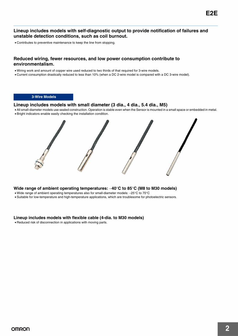
Lineup includes models with self-diagnostic output to provide notification of failures and unstable detection conditions, such as coil burnout.• Contributes to preventive maintenance to keep the line from stopping.
Reduced wiring, fewer resources, and low power consumption contribute to environmentalism. • Wiring work and amount of copper wire used reduced to two thirds of that required for 3-wire models. • Current consumption drastically reduced to less than 10% (when a DC 2-wire model is compared with a DC 3-wire model).
Lineup includes models with small diameter (3 dia., 4 dia., 5.4 dia., M5)• All small-diameter models use sealed construction. Operation is stable even when the Sensor is mounted in a small space or embedded in metal. • Bright indicators enable easily checking the installation condition.
Wide range of ambient operating temperatures: −40°C to 85°C (M8 to M30 models)• Wide range of ambient operating temperatures also for small-diameter models: −25°C to 70°C • Suitable for low-temperature and high-temperature applications, which are troublesome for photoelectric sensors.
Lineup includes models with flexible cable (4-dia. to M30 models)• Reduced risk of disconnection in applications with moving parts.
3-Wire Models
E2E
3
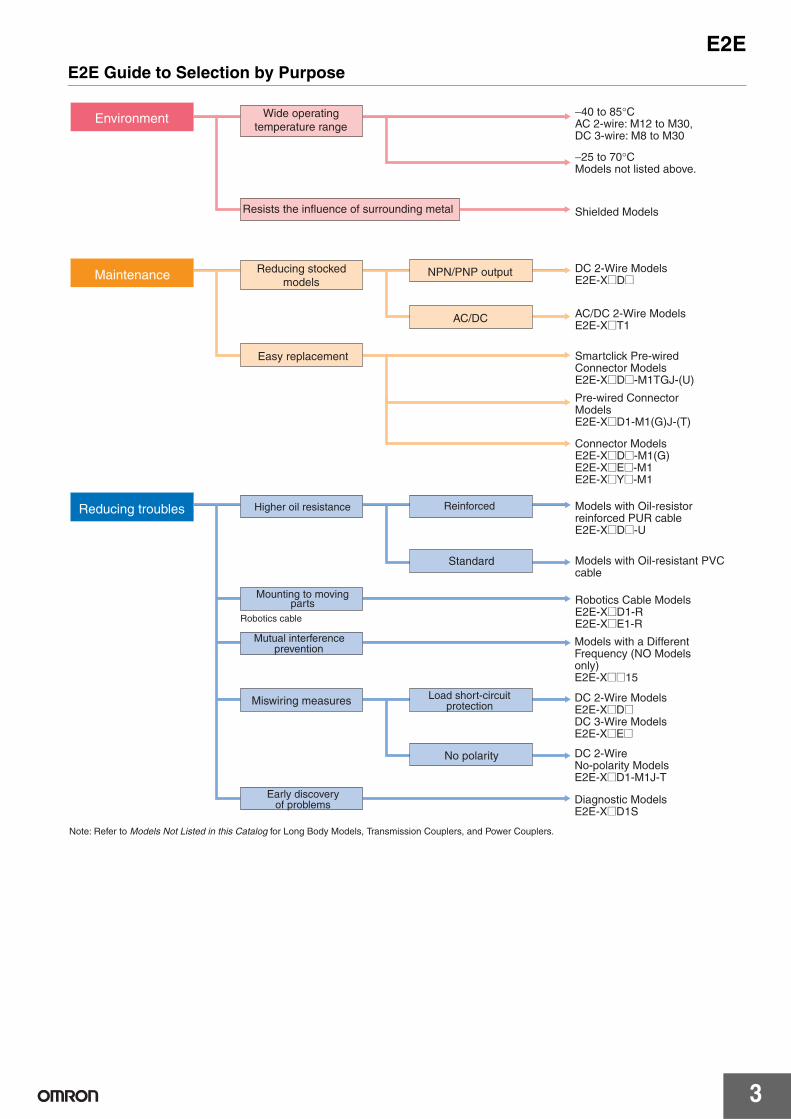
E2E Guide to Selection by Purpose
Environment
Maintenance
Reducing troubles Higher oil resistance
Easy replacement
Reducing stocked models
Wide operating temperature range
Resists the influence of surrounding metal
Mutual interference prevention
Miswiring measures
Early discovery of problems
AC/DC 2-Wire ModelsE2E-X@T1
Connector ModelsE2E-X@D@-M1(G)E2E-X@E@-M1E2E-X@Y@-M1
Pre-wired Connector ModelsE2E-X@D1-M1(G)J-(T)
Smartclick Pre-wired Connector ModelsE2E-X@D@-M1TGJ-(U)
Models with Oil-resistor reinforced PUR cable E2E-X@D@-U
Models with a Different Frequency (NO Models only)E2E-X@@15
DC 2-Wire ModelsE2E-X@D@DC 3-Wire ModelsE2E-X@E@
DC 2-Wire No-polarity ModelsE2E-X@D1-M1J-T
Diagnostic ModelsE2E-X@D1S
−40 to 85°CAC 2-wire: M12 to M30, DC 3-wire: M8 to M30
−25 to 70°CModels not listed above.
Shielded Models
DC 2-Wire ModelsE2E-X@D@
NPN/PNP output
AC/DC
Load short-circuit protection
No polarity
Mounting to moving parts Robotics Cable Models
E2E-X@D1-RE2E-X@E1-RRobotics cable
Note: Refer to Models Not Listed in this Catalog for Long Body Models, Transmission Couplers, and Power Couplers.
Reinforced
Standard Models with Oil-resistant PVC cable
4
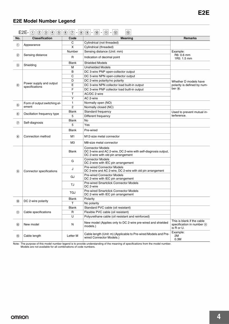
E2EE2E Model Number Legend
Note: The purpose of this model number legend is to provide understanding of the meaning of specifications from the model number. Models are not available for all combinations of code numbers.
E2E- A B C D E F G H I - J - K - L- M
No. Classification Code Meaning Remarks
A AppearanceC Cylindrical (not threaded)X Cylindrical (threaded)
B Sensing distanceNumber Sensing distance (Unit: mm) Example:
R6: 0.6 mm1R5: 1.5 mmR Indication of decimal point
C ShieldingBlank Shielded Models
M Unshielded Models
DPower supply and output specifications
B DC 3-wire PNP open-collector output
Whether D models have polarity is defined by num-ber J.
C DC 3-wire NPN open-collector outputD DC 2-wire polarity/no polarityE DC 3-wire NPN collector load built-in output F DC 3-wire PNP collector load built-in output T AC/DC 2-wireY AC 2-wire
EForm of output switching el-ement
1 Normally open (NO)2 Normally closed (NC)
F Oscillation frequency typeBlank Standard frequency Used to prevent mutual in-
terference.5 Different frequency
G Self-diagnosisBlank No
5 Yes
H Connection method
Blank Pre-wired
M1 M12-size metal connector
M3 M8-size metal connector
I Connector specifications
BlankConnector Models DC 3-wire and AC 2-wire, DC 2-wire with self-diagnosis output, DC 2-wire with old pin arrangement
G Connector Models DC 2-wire with IEC pin arrangement
J Pre-wired Connector ModelsDC 3-wire and AC 2-wire, DC 2-wire with old pin arrangement
GJ Pre-wired Connector Models DC 2-wire with IEC pin arrangement
TJ Pre-wired Smartclick Connector Models DC 2-wire
TGJ Pre-wired Smartclick Connector ModelsDC 2-wire with IEC pin arrangement
J DC 2-wire polarityBlank Polarity
T No polarity
K Cable specificationsBlank Standard PVC cable (oil resistant)
R Flexible PVC cable (oil resistant)U Polyurethane cable (oil resistant and reinforced)
L New model N New model (Applies only to DC 2-wire pre-wired and shielded models.)
This is blank if the cable specification in number K is R or U.
M Cable length Letter M Cable length (Unit: m) (Applicable to Pre-wired Models and Pre-wired Connector Models.)
Example:2M0.3M
E2E
5
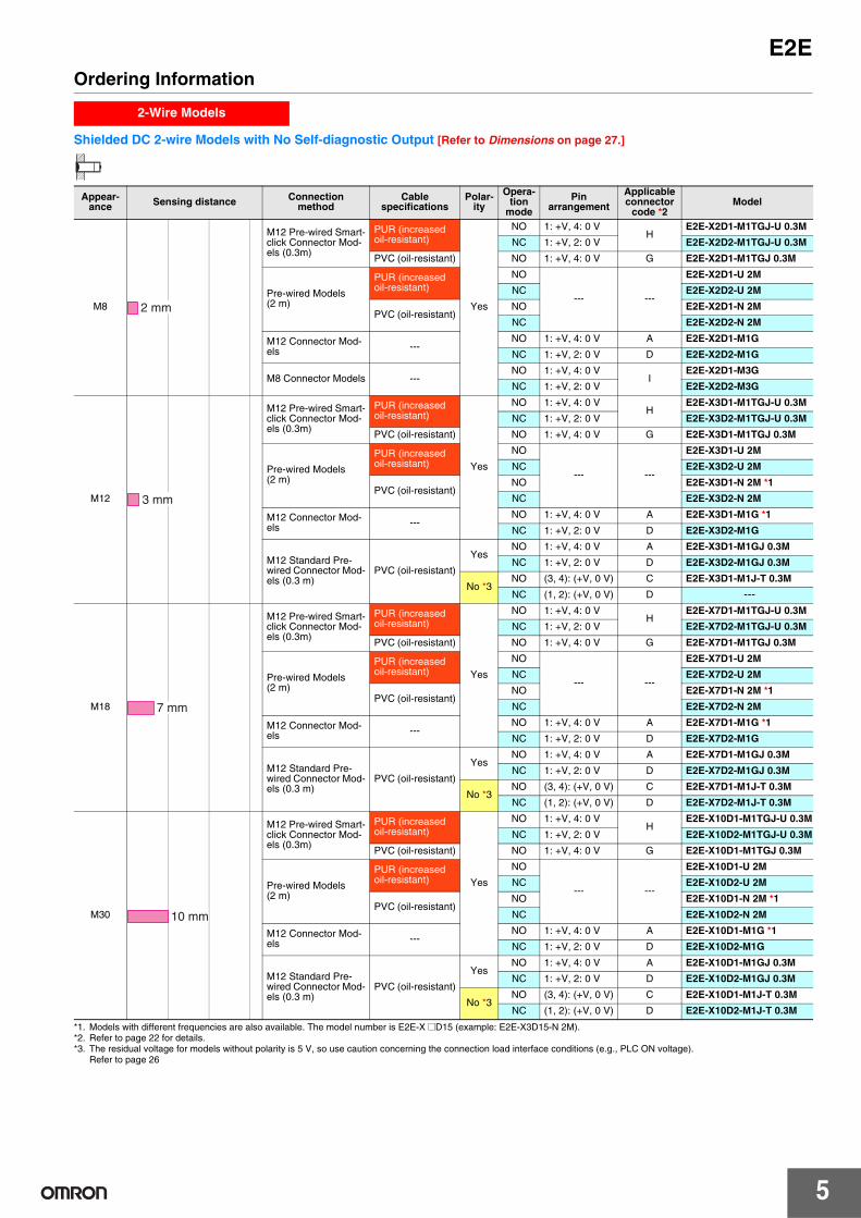
Ordering Information
Shielded DC 2-wire Models with No Self-diagnostic Output [Refer to Dimensions on page 27.]
*1. Models with different frequencies are also available. The model number is E2E-X @D15 (example: E2E-X3D15-N 2M).*2. Refer to page 22 for details.*3. The residual voltage for models without polarity is 5 V, so use caution concerning the connection load interface conditions (e.g., PLC ON voltage).
Refer to page 26
2-Wire Models
Appear-ance Sensing distance Connection
methodCable
specificationsPolar-
ity
Opera-tion
mode
Pin arrangement
Applicable connector
code *2Model
M8
M12 Pre-wired Smart-click Connector Mod-els (0.3m)
PUR (increased oil-resistant)
Yes
NO 1: +V, 4: 0 VH
E2E-X2D1-M1TGJ-U 0.3M
NC 1: +V, 2: 0 V E2E-X2D2-M1TGJ-U 0.3M
PVC (oil-resistant) NO 1: +V, 4: 0 V G E2E-X2D1-M1TGJ 0.3M
Pre-wired Models (2 m)
PUR (increased oil-resistant)
NO
--- ---
E2E-X2D1-U 2M
NC E2E-X2D2-U 2M
PVC (oil-resistant)NO E2E-X2D1-N 2M
NC E2E-X2D2-N 2M
M12 Connector Mod-els ---
NO 1: +V, 4: 0 V A E2E-X2D1-M1G
NC 1: +V, 2: 0 V D E2E-X2D2-M1G
M8 Connector Models ---NO 1: +V, 4: 0 V
IE2E-X2D1-M3G
NC 1: +V, 2: 0 V E2E-X2D2-M3G
M12
M12 Pre-wired Smart-click Connector Mod-els (0.3m)
PUR (increased oil-resistant)
Yes
NO 1: +V, 4: 0 VH
E2E-X3D1-M1TGJ-U 0.3M
NC 1: +V, 2: 0 V E2E-X3D2-M1TGJ-U 0.3M
PVC (oil-resistant) NO 1: +V, 4: 0 V G E2E-X3D1-M1TGJ 0.3M
Pre-wired Models (2 m)
PUR (increased oil-resistant)
NO
--- ---
E2E-X3D1-U 2M
NC E2E-X3D2-U 2M
PVC (oil-resistant)NO E2E-X3D1-N 2M *1
NC E2E-X3D2-N 2M
M12 Connector Mod-els ---
NO 1: +V, 4: 0 V A E2E-X3D1-M1G *1
NC 1: +V, 2: 0 V D E2E-X3D2-M1G
M12 Standard Pre-wired Connector Mod-els (0.3 m)
PVC (oil-resistant)
YesNO 1: +V, 4: 0 V A E2E-X3D1-M1GJ 0.3M
NC 1: +V, 2: 0 V D E2E-X3D2-M1GJ 0.3M
No *3NO (3, 4): (+V, 0 V) C E2E-X3D1-M1J-T 0.3M
NC (1, 2): (+V, 0 V) D ---
M18
M12 Pre-wired Smart-click Connector Mod-els (0.3m)
PUR (increased oil-resistant)
Yes
NO 1: +V, 4: 0 VH
E2E-X7D1-M1TGJ-U 0.3M
NC 1: +V, 2: 0 V E2E-X7D2-M1TGJ-U 0.3M
PVC (oil-resistant) NO 1: +V, 4: 0 V G E2E-X7D1-M1TGJ 0.3M
Pre-wired Models (2 m)
PUR (increased oil-resistant)
NO
--- ---
E2E-X7D1-U 2M
NC E2E-X7D2-U 2M
PVC (oil-resistant)NO E2E-X7D1-N 2M *1
NC E2E-X7D2-N 2M
M12 Connector Mod-els ---
NO 1: +V, 4: 0 V A E2E-X7D1-M1G *1
NC 1: +V, 2: 0 V D E2E-X7D2-M1G
M12 Standard Pre-wired Connector Mod-els (0.3 m)
PVC (oil-resistant)
YesNO 1: +V, 4: 0 V A E2E-X7D1-M1GJ 0.3M
NC 1: +V, 2: 0 V D E2E-X7D2-M1GJ 0.3M
No *3NO (3, 4): (+V, 0 V) C E2E-X7D1-M1J-T 0.3M
NC (1, 2): (+V, 0 V) D E2E-X7D2-M1J-T 0.3M
M30
M12 Pre-wired Smart-click Connector Mod-els (0.3m)
PUR (increased oil-resistant)
Yes
NO 1: +V, 4: 0 VH
E2E-X10D1-M1TGJ-U 0.3M
NC 1: +V, 2: 0 V E2E-X10D2-M1TGJ-U 0.3M
PVC (oil-resistant) NO 1: +V, 4: 0 V G E2E-X10D1-M1TGJ 0.3M
Pre-wired Models (2 m)
PUR (increased oil-resistant)
NO
--- ---
E2E-X10D1-U 2M
NC E2E-X10D2-U 2M
PVC (oil-resistant)NO E2E-X10D1-N 2M *1
NC E2E-X10D2-N 2M
M12 Connector Mod-els ---
NO 1: +V, 4: 0 V A E2E-X10D1-M1G *1
NC 1: +V, 2: 0 V D E2E-X10D2-M1G
M12 Standard Pre-wired Connector Mod-els (0.3 m)
PVC (oil-resistant)
YesNO 1: +V, 4: 0 V A E2E-X10D1-M1GJ 0.3M
NC 1: +V, 2: 0 V D E2E-X10D2-M1GJ 0.3M
No *3NO (3, 4): (+V, 0 V) C E2E-X10D1-M1J-T 0.3M
NC (1, 2): (+V, 0 V) D E2E-X10D2-M1J-T 0.3M
2 mm
3 mm
7 mm
10 mm
6
E2E
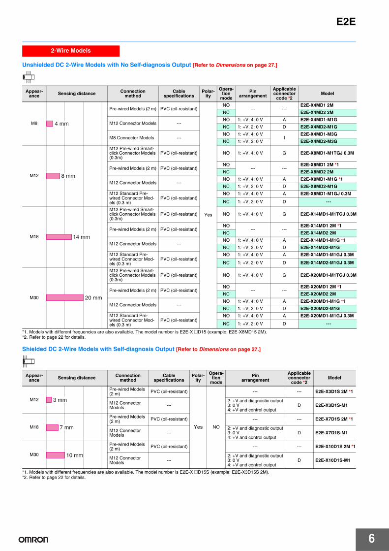
Unshielded DC 2-Wire Models with No Self-diagnosis Output [Refer to Dimensions on page 27.]
*1. Models with different frequencies are also available. The model number is E2E-X @D15 (example: E2E-X8MD15 2M).*2. Refer to page 22 for details.
Shielded DC 2-Wire Models with Self-diagnosis Output [Refer to Dimensions on page 27.]
*1. Models with different frequencies are also available. The model number is E2E-X @D15S (example: E2E-X3D15S 2M).*2. Refer to page 22 for details.
2-Wire Models
Appear-ance Sensing distance Connection
methodCable
specificationsPolar-
ity
Opera-tion
mode
Pin arrangement
Applicable connector
code *2Model
M8
Pre-wired Models (2 m) PVC (oil-resistant)
Yes
NO--- ---
E2E-X4MD1 2M
NC E2E-X4MD2 2M
M12 Connector Models ---NO 1: +V, 4: 0 V A E2E-X4MD1-M1G
NC 1: +V, 2: 0 V D E2E-X4MD2-M1G
M8 Connector Models ---NO 1: +V, 4: 0 V
IE2E-X4MD1-M3G
NC 1: +V, 2: 0 V E2E-X4MD2-M3G
M12
M12 Pre-wired Smart-click Connector Models (0.3m)
PVC (oil-resistant) NO 1: +V, 4: 0 V G E2E-X8MD1-M1TGJ 0.3M
Pre-wired Models (2 m) PVC (oil-resistant)NO
--- ---E2E-X8MD1 2M *1
NC E2E-X8MD2 2M
M12 Connector Models ---NO 1: +V, 4: 0 V A E2E-X8MD1-M1G *1
NC 1: +V, 2: 0 V D E2E-X8MD2-M1G
M12 Standard Pre-wired Connector Mod-els (0.3 m)
PVC (oil-resistant)NO 1: +V, 4: 0 V A E2E-X8MD1-M1GJ 0.3M
NC 1: +V, 2: 0 V D ---
M18
M12 Pre-wired Smart-click Connector Models (0.3m)
PVC (oil-resistant) NO 1: +V, 4: 0 V G E2E-X14MD1-M1TGJ 0.3M
Pre-wired Models (2 m) PVC (oil-resistant)NO
--- ---E2E-X14MD1 2M *1
NC E2E-X14MD2 2M
M12 Connector Models ---NO 1: +V, 4: 0 V A E2E-X14MD1-M1G *1
NC 1: +V, 2: 0 V D E2E-X14MD2-M1G
M12 Standard Pre-wired Connector Mod-els (0.3 m)
PVC (oil-resistant)NO 1: +V, 4: 0 V A E2E-X14MD1-M1GJ 0.3M
NC 1: +V, 2: 0 V D E2E-X14MD2-M1GJ 0.3M
M30
M12 Pre-wired Smart-click Connector Models (0.3m)
PVC (oil-resistant) NO 1: +V, 4: 0 V G E2E-X20MD1-M1TGJ 0.3M
Pre-wired Models (2 m) PVC (oil-resistant)NO
--- ---E2E-X20MD1 2M *1
NC E2E-X20MD2 2M
M12 Connector Models ---NO 1: +V, 4: 0 V A E2E-X20MD1-M1G *1
NC 1: +V, 2: 0 V D E2E-X20MD2-M1G
M12 Standard Pre-wired Connector Mod-els (0.3 m)
PVC (oil-resistant)NO 1: +V, 4: 0 V A E2E-X20MD1-M1GJ 0.3M
NC 1: +V, 2: 0 V D ---
4 mm
8 mm
14 mm
20 mm
Appear-ance Sensing distance Connection
methodCable
specificationsPolar-
ity
Opera-tion
mode
Pin arrangement
Applicable connector
code *2Model
M12
Pre-wired Models (2 m) PVC (oil-resistant)
Yes NO
--- --- E2E-X3D1S 2M *1
M12 Connector Models ---
2: +V and diagnostic output3: 0 V4: +V and control output
D E2E-X3D1S-M1
M18
Pre-wired Models (2 m) PVC (oil-resistant) --- --- E2E-X7D1S 2M *1
M12 Connector Models ---
2: +V and diagnostic output3: 0 V4: +V and control output
D E2E-X7D1S-M1
M30
Pre-wired Models (2 m) PVC (oil-resistant) --- --- E2E-X10D1S 2M *1
M12 Connector Models ---
2: +V and diagnostic output3: 0 V4: +V and control output
D E2E-X10D1S-M1
3 mm
7 mm
10 mm
E2E
7
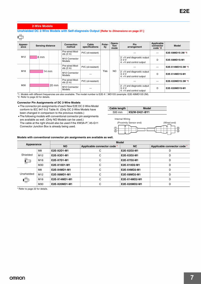
Unshielded DC 2-Wire Models with Self-diagnosis Output [Refer to Dimensions on page 27.]
*1. Models with different frequencies are also available. The model number is E2E-X @MD15S (example: E2E-X8MD15S 2M).*2. Refer to page 22 for details.
Connector Pin Assignments of DC 2-Wire Models• The connector pin assignments of each New E2E DC 2-Wire Model
conform to IEC 947-5-2 Table III. (Only DC 2-Wire Models have been changed in comparison to the previous models.)
• The following models with conventional connector pin assignments are available as well. (Only NO Models can be used.)The cable at the right should also be used if the XW3A-P@45-G11 Connector Junction Box is already being used.
Models with conventional connector pin assignments are available as well.
* Refer to page 22 for details.
2-Wire Models
Appear-ance Sensing distance Connection
methodCable
specificationsPolar-
ity
Opera-tion
mode
Pin arrangement
Applicable connector
code *2Model
M12
Pre-wired Mod-els (2 m) PVC (oil-resistant)
Yes NO
--- --- E2E-X8MD1S 2M *1
M12 Connector Models ---
2: +V and diagnostic output3: 0 V4: +V and control output
D E2E-X8MD1S-M1
M18
Pre-wired Mod-els (2 m) PVC (oil-resistant) --- --- E2E-X14MD1S 2M *1
M12 Connector Models ---
2: +V and diagnostic output3: 0 V4: +V and control output
D E2E-X14MD1S-M1
M30
Pre-wired Mod-els (2 m) PVC (oil-resistant) --- --- E2E-X20MD1S 2M *1
M12 Connector Models ---
2: +V and diagnostic output3: 0 V4: +V and control output
D E2E-X20MD1S-M1
8 mm
14 mm
20 mm
Cable length Model500 mm XS2W-D421-BY1
34
41
Internal Wiring
(Proximity Sensor end) (Wired end)
AppearanceModel
NO Applicable connector code * NC Applicable connector code *
M8 E2E-X2D1-M1 C E2E-X2D2-M1 D
M12 E2E-X3D1-M1 C E2E-X3D2-M1 D
M18 E2E-X7D1-M1 C E2E-X7D2-M1 D
M30 E2E-X10D1-M1 C E2E-X10D2-M1 D
M8 E2E-X4MD1-M1 C E2E-X4MD2-M1 D
M12 E2E-X8MD1-M1 C E2E-X8MD2-M1 D
M18 E2E-X14MD1-M1 C E2E-X14MD2-M1 D
M30 E2E-X20MD1-M1 C E2E-X20MD2-M1 D
Shielded
Unshielded
8
E2E
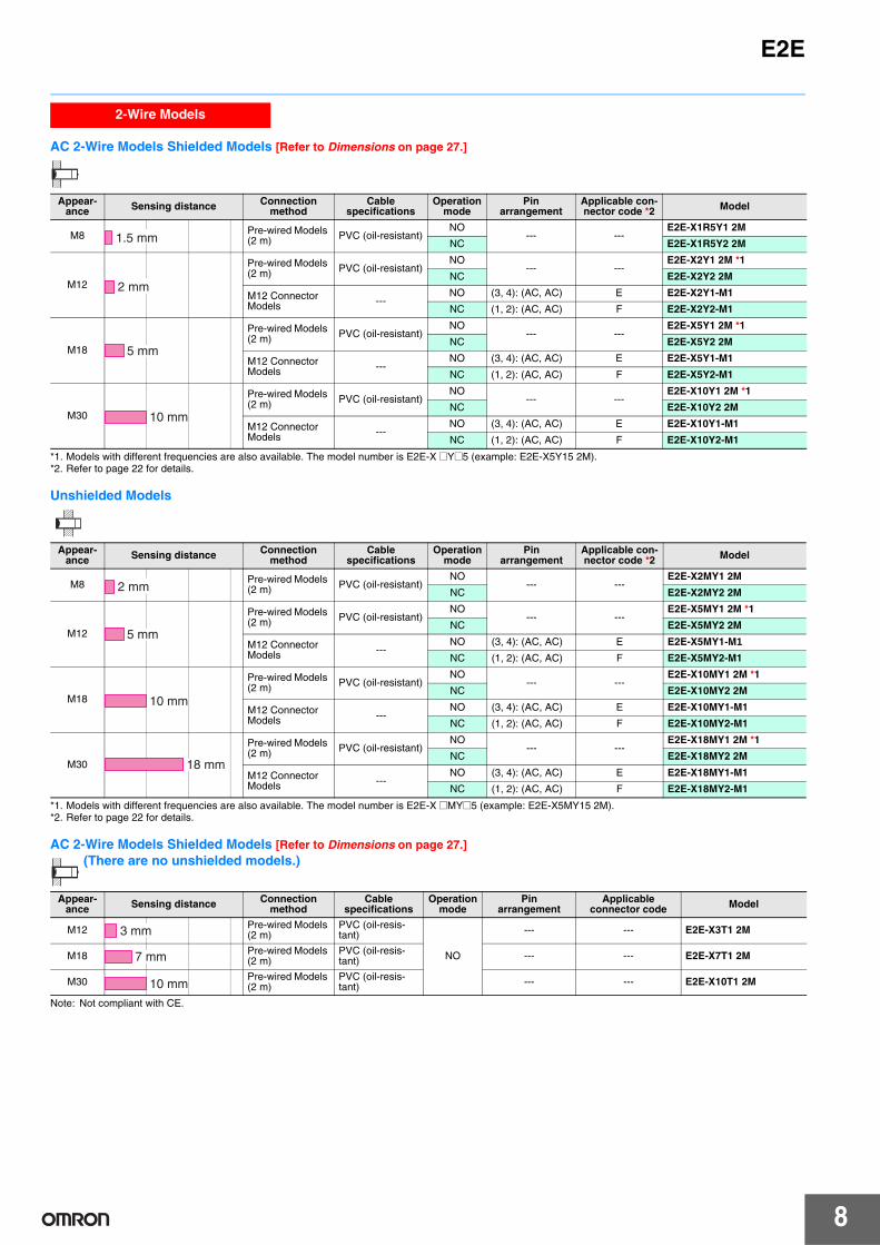
AC 2-Wire Models Shielded Models [Refer to Dimensions on page 27.]
*1. Models with different frequencies are also available. The model number is E2E-X @Y@5 (example: E2E-X5Y15 2M).*2. Refer to page 22 for details.
Unshielded Models
*1. Models with different frequencies are also available. The model number is E2E-X @MY@5 (example: E2E-X5MY15 2M).*2. Refer to page 22 for details.
AC 2-Wire Models Shielded Models [Refer to Dimensions on page 27.] (There are no unshielded models.)
Note: Not compliant with CE.
2-Wire Models
Appear-ance Sensing distance Connection
methodCable
specificationsOperation
modePin
arrangementApplicable con-nector code *2 Model
M8 Pre-wired Models (2 m) PVC (oil-resistant)
NO--- ---
E2E-X1R5Y1 2M
NC E2E-X1R5Y2 2M
M12
Pre-wired Models (2 m) PVC (oil-resistant)
NO--- ---
E2E-X2Y1 2M *1
NC E2E-X2Y2 2M
M12 Connector Models ---
NO (3, 4): (AC, AC) E E2E-X2Y1-M1
NC (1, 2): (AC, AC) F E2E-X2Y2-M1
M18
Pre-wired Models (2 m) PVC (oil-resistant)
NO--- ---
E2E-X5Y1 2M *1
NC E2E-X5Y2 2M
M12 Connector Models ---
NO (3, 4): (AC, AC) E E2E-X5Y1-M1
NC (1, 2): (AC, AC) F E2E-X5Y2-M1
M30
Pre-wired Models (2 m) PVC (oil-resistant)
NO--- ---
E2E-X10Y1 2M *1
NC E2E-X10Y2 2M
M12 Connector Models ---
NO (3, 4): (AC, AC) E E2E-X10Y1-M1
NC (1, 2): (AC, AC) F E2E-X10Y2-M1
1.5 mm
2 mm
5 mm
10 mm
Appear-ance Sensing distance Connection
methodCable
specificationsOperation
modePin
arrangementApplicable con-nector code *2 Model
M8 Pre-wired Models (2 m) PVC (oil-resistant)
NO--- ---
E2E-X2MY1 2M
NC E2E-X2MY2 2M
M12
Pre-wired Models (2 m) PVC (oil-resistant)
NO--- ---
E2E-X5MY1 2M *1
NC E2E-X5MY2 2M
M12 Connector Models ---
NO (3, 4): (AC, AC) E E2E-X5MY1-M1NC (1, 2): (AC, AC) F E2E-X5MY2-M1
M18
Pre-wired Models (2 m) PVC (oil-resistant)
NO--- ---
E2E-X10MY1 2M *1
NC E2E-X10MY2 2M
M12 Connector Models ---
NO (3, 4): (AC, AC) E E2E-X10MY1-M1
NC (1, 2): (AC, AC) F E2E-X10MY2-M1
M30
Pre-wired Models (2 m) PVC (oil-resistant)
NO--- ---
E2E-X18MY1 2M *1
NC E2E-X18MY2 2M
M12 Connector Models ---
NO (3, 4): (AC, AC) E E2E-X18MY1-M1
NC (1, 2): (AC, AC) F E2E-X18MY2-M1
2 mm
5 mm
10 mm
18 mm
Appear-ance Sensing distance Connection
methodCable
specificationsOperation
modePin
arrangementApplicable
connector code Model
M12 Pre-wired Models (2 m)
PVC (oil-resis-tant)
NO
--- --- E2E-X3T1 2M
M18 Pre-wired Models (2 m)
PVC (oil-resis-tant) --- --- E2E-X7T1 2M
M30 Pre-wired Models (2 m)
PVC (oil-resis-tant) --- --- E2E-X10T1 2M
3 mm
7 mm
10 mm
E2E
9
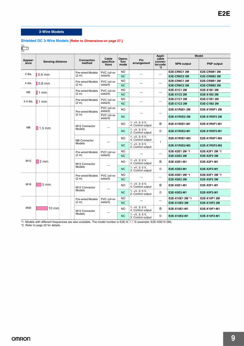
Shielded DC 3-Wire Models [Refer to Dimensions on page 27.]
*1. Models with different frequencies are also available. The model number is E2E-X@@@5 (example: E2E-X5E15 2M).*2. Refer to page 22 for details.
3-Wire Models
Appear-ance Sensing distance Connection
method
Cable specifica-
tions
Opera-tion
mode
Pin arrangement
Appli-cable
connec-tor code
*2
Model
NPN output PNP output
3 dia. Pre-wired Models (2 m)
PVC (oil-re-sistant)
NO--- ---
E2E-CR6C1 2M E2E-CR6B1 2M
NC E2E-CR6C2 2M E2E-CR6B2 2M
4 dia. Pre-wired Models (2 m)
PVC (oil-re-sistant)
NO--- ---
E2E-CR8C1 2M E2E-CR8B1 2M
NC E2E-CR8C2 2M E2E-CR8B2 2M
M5 Pre-wired Models (2 m)
PVC (oil-re-sistant)
NO--- ---
E2E-X1C1 2M E2E-X1B1 2M
NC E2E-X1C2 2M E2E-X1B2 2M
5.4 dia. Pre-wired Models (2 m)
PVC (oil-re-sistant)
NO--- ---
E2E-C1C1 2M E2E-C1B1 2M
NC E2E-C1C2 2M E2E-C1B2 2M
M8
Pre-wired Models (2 m)
PVC (oil-re-sistant) NO
--- ---E2E-X1R5E1 2M E2E-X1R5F1 2M
PVC (oil-re-sistant) NC E2E-X1R5E2 2M E2E-X1R5F2 2M
M12 Connector Models ---
NO 1: +V, 3: 0 V,4: Control output B E2E-X1R5E1-M1 E2E-X1R5F1-M1
NC 1: +V, 3: 0 V,2: Control output D E2E-X1R5E2-M1 E2E-X1R5F2-M1
M8 Connector Models ---
NO 1: +V, 3: 0 V,4: Control output
IE2E-X1R5E1-M3 E2E-X1R5F1-M3
NC 1: +V, 3: 0 V,2: Control output E2E-X1R5E2-M3 E2E-X1R5F2-M3
M12
Pre-wired Models (2 m)
PVC (oil-re-sistant)
NO--- ---
E2E-X2E1 2M *1 E2E-X2F1 2M *1
NC E2E-X2E2 2M E2E-X2F2 2M
M12 Connector Models ---
NO 1: +V, 3: 0 V,4: Control output B E2E-X2E1-M1 E2E-X2F1-M1
NC 1: +V, 3: 0 V,2: Control output D E2E-X2E2-M1 E2E-X2F2-M1
M18
Pre-wired Models (2 m)
PVC (oil-re-sistant)
NO--- ---
E2E-X5E1 2M *1 E2E-X5F1 2M *1
NC E2E-X5E2 2M E2E-X5F2 2M
M12 Connector Models ---
NO 1: +V, 3: 0 V,4: Control output B E2E-X5E1-M1 E2E-X5F1-M1
NC 1: +V, 3: 0 V,2: Control output D E2E-X5E2-M1 E2E-X5F2-M1
M30
Pre-wired Models (2 m)
PVC (oil-re-sistant)
NO--- ---
E2E-X10E1 2M *1 E2E-X10F1 2M
NC E2E-X10E2 2M E2E-X10F2 2M
M12 Connector Models ---
NO 1: +V, 3: 0 V,4: Control output B E2E-X10E1-M1 E2E-X10F1-M1
NC 1: +V, 3: 0 V,2: Control output D E2E-X10E2-M1 E2E-X10F2-M1
0.6 mm
0.8 mm
1 mm
1 mm
1.5 mm
2 mm
5 mm
10 mm

10
E2E
Unshielded DC 3-Wire Models [Refer to Dimensions on page 27.]
*1. Models with different frequencies are also available. The model number is E2E-X@M@@5 (example: E2E-X5ME15 2M).*2. Refer to page 22 for details.
3-Wire Models
Appear-ance Sensing distance Connection
methodCable
specifications
Opera-tion
mode
Pin arrangement
Appli-cable
connec-tor code
*2
Model
NPN output PNP output
M8
Pre-wired Models (2 m)
PVC (oil-resis-tant)
NO--- ---
E2E-X2ME1 2M E2E-X2MF1 2M
NC E2E-X2ME2 2M E2E-X2MF2 2M
M12 Connector Models ---
NO 1: +V, 3: 0 V,4: Control output B E2E-X2ME1-M1 E2E-X2MF1-M1
NC 1: +V, 3: 0 V,2: Control output D E2E-X2ME2-M1 E2E-X2MF2-M1
M8 Connector Models ---
NO 1: +V, 3: 0 V,4: Control output
IE2E-X2ME1-M3 E2E-X2MF1-M3
NC 1: +V, 3: 0 V,2: Control output E2E-X2ME2-M3 E2E-X2MF2-M3
M12
Pre-wired Models (2 m)
PVC (oil-resis-tant)
NO--- ---
E2E-X5ME1 2M *1 E2E-X5MF1 2M
NC E2E-X5ME2 2M E2E-X5MF2 2M
M12 Connector Models ---
NO 1: +V, 3: 0 V,4: Control output B E2E-X5ME1-M1 E2E-X5MF1-M1
NC 1: +V, 3: 0 V,2: Control output D E2E-X5ME2-M1 E2E-X5MF2-M1
M18
Pre-wired Models (2 m)
PVC (oil-resis-tant)
NO--- ---
E2E-X10ME1 2M *1 E2E-X10MF1 2M
NC E2E-X10ME2 2M E2E-X10MF2 2M
M12 Connector Models ---
NO 1: +V, 3: 0 V,4: Control output B E2E-X10ME1-M1 E2E-X10MF1-M1
NC 1: +V, 3: 0 V,2: Control output D E2E-X10ME2-M1 E2E-X10MF2-M1
M30
Pre-wired Models (2 m)
PVC (oil-resis-tant)
NO--- ---
E2E-X18ME1 2M *1 E2E-X18MF1 2M
NC E2E-X18ME2 2M E2E-X18MF2 2M
M12 Connector Models ---
NO 1: +V, 3: 0 V,4: Control output B E2E-X18ME1-M1 E2E-X18MF1-M1
NC 1: +V, 3: 0 V,2: Control output D E2E-X18ME2-M1 E2E-X18MF2-M1
2 mm
5 mm
10 mm
18 mm
E2E
11
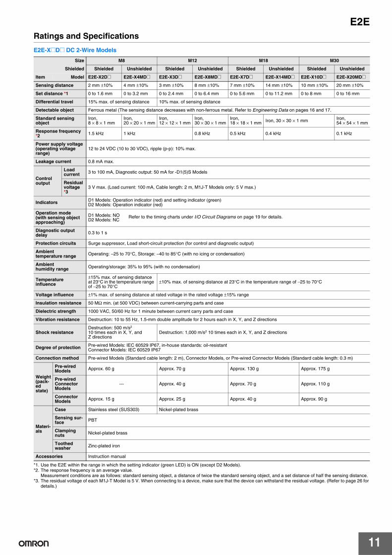
Ratings and Specifications
E2E-X@D@ DC 2-Wire Models
*1. Use the E2E within the range in which the setting indicator (green LED) is ON (except D2 Models).*2. The response frequency is an average value.
Measurement conditions are as follows: standard sensing object, a distance of twice the standard sensing object, and a set distance of half the sensing distance.*3. The residual voltage of each M1J-T Model is 5 V. When connecting to a device, make sure that the device can withstand the residual voltage. (Refer to page 26 for
details.)
Size M8 M12 M18 M30
Shielded Shielded Unshielded Shielded Unshielded Shielded Unshielded Shielded Unshielded
Item Model E2E-X2D@ E2E-X4MD@ E2E-X3D@ E2E-X8MD@ E2E-X7D@ E2E-X14MD@ E2E-X10D@ E2E-X20MD@
Sensing distance 2 mm ±10% 4 mm ±10% 3 mm ±10% 8 mm ±10% 7 mm ±10% 14 mm ±10% 10 mm ±10% 20 mm ±10%
Set distance *1 0 to 1.6 mm 0 to 3.2 mm 0 to 2.4 mm 0 to 6.4 mm 0 to 5.6 mm 0 to 11.2 mm 0 to 8 mm 0 to 16 mm
Differential travel 15% max. of sensing distance 10% max. of sensing distance
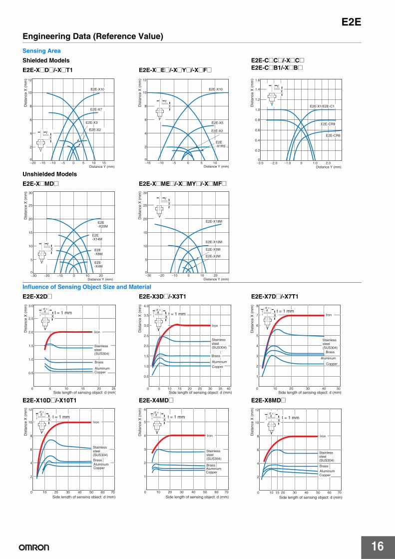
Detectable object Ferrous metal (The sensing distance decreases with non-ferrous metal. Refer to Engineering Data on pages 16 and 17.
Standard sensing object
Iron, 8 × 8 × 1 mm
Iron, 20 × 20 × 1 mm
Iron, 12 × 12 × 1 mm
Iron, 30 × 30 × 1 mm
Iron, 18 × 18 × 1 mm Iron, 30 × 30 × 1 mm Iron,
54 × 54 × 1 mm
Response frequency *2 1.5 kHz 1 kHz 0.8 kHz 0.5 kHz 0.4 kHz 0.1 kHz
Power supply voltage (operating voltage range)
12 to 24 VDC (10 to 30 VDC), ripple (p-p): 10% max.
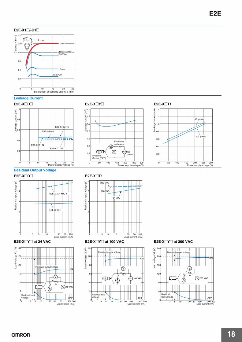
Leakage current 0.8 mA max.
Control output
Load current 3 to 100 mA, Diagnostic output: 50 mA for -D1(5)S Models
Residual voltage
*33 V max. (Load current: 100 mA, Cable length: 2 m, M1J-T Models only: 5 V max.)
Indicators D1 Models: Operation indicator (red) and setting indicator (green)D2 Models: Operation indicator (red)
Operation mode (with sensing object approaching)
D1 Models: NOD2 Models: NC
Diagnostic output delay 0.3 to 1 s
Protection circuits Surge suppressor, Load short-circuit protection (for control and diagnostic output)
Ambient temperature range Operating: −25 to 70°C, Storage: −40 to 85°C (with no icing or condensation)
Ambient humidity range Operating/storage: 35% to 95% (with no condensation)
Temperature influence
±15% max. of sensing distance at 23°C in the temperature range of −25 to 70°C
±10% max. of sensing distance at 23°C in the temperature range of −25 to 70°C
Voltage influence ±1% max. of sensing distance at rated voltage in the rated voltage ±15% range
Insulation resistance 50 MΩ min. (at 500 VDC) between current-carrying parts and case
Dielectric strength 1000 VAC, 50/60 Hz for 1 minute between current carry parts and case
Vibration resistance Destruction: 10 to 55 Hz, 1.5-mm double amplitude for 2 hours each in X, Y, and Z directions
Shock resistanceDestruction: 500 m/s2
10 times each in X, Y, and Z directions
Destruction: 1,000 m/s2 10 times each in X, Y, and Z directions
Degree of protection Pre-wired Models: IEC 60529 IP67, in-house standards: oil-resistantConnector Models: IEC 60529 IP67
Connection method Pre-wired Models (Standard cable length: 2 m), Connector Models, or Pre-wired Connector Models (Standard cable length: 0.3 m)
Weight (pack-ed state)
Pre-wired Models Approx. 60 g Approx. 70 g Approx. 130 g Approx. 175 g
Pre-wired Connector Models
--- Approx. 40 g Approx. 70 g Approx. 110 g
Connector Models Approx. 15 g Approx. 25 g Approx. 40 g Approx. 90 g
Materi-als
Case Stainless steel (SUS303) Nickel-plated brass
Sensing sur-face PBT
Clamping nuts Nickel-plated brass
Toothed washer Zinc-plated iron
Accessories Instruction manual
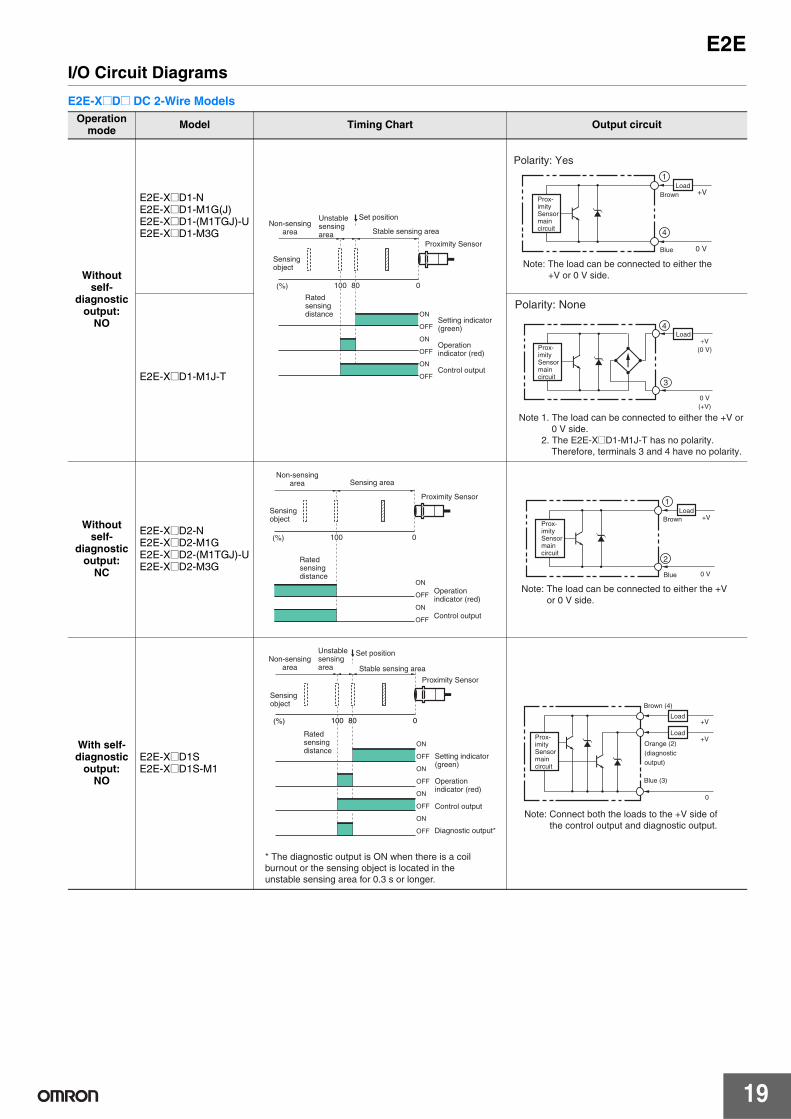
Refer to the timing charts under I/O Circuit Diagrams on page 19 for details.
12
E2E
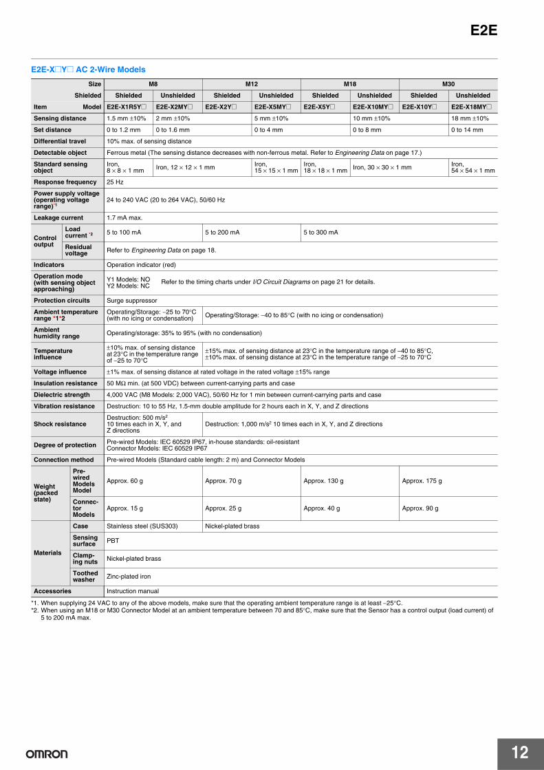
E2E-X@Y@ AC 2-Wire Models
*1. When supplying 24 VAC to any of the above models, make sure that the operating ambient temperature range is at least −25°C. *2. When using an M18 or M30 Connector Model at an ambient temperature between 70 and 85°C, make sure that the Sensor has a control output (load current) of
5 to 200 mA max.
Size M8 M12 M18 M30
Shielded Shielded Unshielded Shielded Unshielded Shielded Unshielded Shielded Unshielded
Item Model E2E-X1R5Y@ E2E-X2MY@ E2E-X2Y@ E2E-X5MY@ E2E-X5Y@ E2E-X10MY@ E2E-X10Y@ E2E-X18MY@
Sensing distance 1.5 mm ±10% 2 mm ±10% 5 mm ±10% 10 mm ±10% 18 mm ±10%
Set distance 0 to 1.2 mm 0 to 1.6 mm 0 to 4 mm 0 to 8 mm 0 to 14 mm
Differential travel 10% max. of sensing distance
Detectable object Ferrous metal (The sensing distance decreases with non-ferrous metal. Refer to Engineering Data on page 17.)
Standard sensing object
Iron, 8 × 8 × 1 mm Iron, 12 × 12 × 1 mm Iron,
15 × 15 × 1 mmIron, 18 × 18 × 1 mm Iron, 30 × 30 × 1 mm Iron,
54 × 54 × 1 mm
Response frequency 25 Hz
Power supply voltage (operating voltage range)*1
24 to 240 VAC (20 to 264 VAC), 50/60 Hz
Leakage current 1.7 mA max.
Control output
Load current *2 5 to 100 mA 5 to 200 mA 5 to 300 mA
Residual voltage Refer to Engineering Data on page 18.
Indicators Operation indicator (red)
Operation mode (with sensing object approaching)
Y1 Models: NOY2 Models: NC
Protection circuits Surge suppressor
Ambient temperature range *1*2
Operating/Storage: −25 to 70°C (with no icing or condensation) Operating/Storage: −40 to 85°C (with no icing or condensation)
Ambient humidity range Operating/storage: 35% to 95% (with no condensation)
Temperature influence
±10% max. of sensing distance at 23°C in the temperature range of −25 to 70°C
±15% max. of sensing distance at 23°C in the temperature range of −40 to 85°C, ±10% max. of sensing distance at 23°C in the temperature range of −25 to 70°C
Voltage influence ±1% max. of sensing distance at rated voltage in the rated voltage ±15% range
Insulation resistance 50 MΩ min. (at 500 VDC) between current-carrying parts and case
Dielectric strength 4,000 VAC (M8 Models: 2,000 VAC), 50/60 Hz for 1 min between current-carrying parts and case
Vibration resistance Destruction: 10 to 55 Hz, 1.5-mm double amplitude for 2 hours each in X, Y, and Z directions
Shock resistanceDestruction: 500 m/s2
10 times each in X, Y, and Z directions
Destruction: 1,000 m/s2 10 times each in X, Y, and Z directions
Degree of protection Pre-wired Models: IEC 60529 IP67, in-house standards: oil-resistantConnector Models: IEC 60529 IP67
Connection method Pre-wired Models (Standard cable length: 2 m) and Connector Models
Weight(packed state)
Pre-wired ModelsModel
Approx. 60 g Approx. 70 g Approx. 130 g Approx. 175 g
Connec-tor Models
Approx. 15 g Approx. 25 g Approx. 40 g Approx. 90 g
Materials
Case Stainless steel (SUS303) Nickel-plated brass
Sensing surface PBT
Clamp-ing nuts Nickel-plated brass
Toothed washer Zinc-plated iron
Accessories Instruction manual
Refer to the timing charts under I/O Circuit Diagrams on page 21 for details.
E2E
13
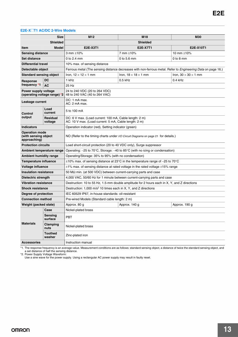
E2E-X@T1 AC/DC 2-Wire Models
*1. The response frequency is an average value. Measurement conditions are as follows: standard sensing object, a distance of twice the standard sensing object, and a set distance of half the sensing distance.
*2. Power Supply Voltage Waveform:Use a sine wave for the power supply. Using a rectangular AC power supply may result in faulty reset.
Size M12 M18 M30
Shielded Shielded
Item Model E2E-X3T1 E2E-X7T1 E2E-X10T1
Sensing distance 3 mm ±10% 7 mm ±10% 10 mm ±10%
Set distance 0 to 2.4 mm 0 to 5.6 mm 0 to 8 mm
Differential travel 10% max. of sensing distance
Detectable object Ferrous metal (The sensing distance decreases with non-ferrous metal. Refer to Engineering Data on page 16.)
Standard sensing object Iron, 12 × 12 × 1 mm Iron, 18 × 18 × 1 mm Iron, 30 × 30 × 1 mm
Response frequency *1
DC 1 kHz 0.5 kHz 0.4 kHz
AC 25 Hz
Power supply voltage (operating voltage range) *2
24 to 240 VDC (20 to 264 VDC)48 to 240 VAC (40 to 264 VAC)
Leakage current DC: 1 mA max. AC: 2 mA max.
Control output
Load current 5 to 100 mA
Residual voltage
DC: 6 V max. (Load current: 100 mA, Cable length: 2 m)AC: 10 V max. (Load current: 5 mA, Cable length: 2 m)
Indicators Operation indicator (red), Setting indicator (green)
Operation mode (with sensing object approaching)
NO (Refer to the timing charts under I/O Circuit Diagrams on page 21 for details.)
Protection circuits Load short-circuit protection (20 to 40 VDC only), Surge suppressor
Ambient temperature range Operating: −25 to 70°C, Storage: −40 to 85°C (with no icing or condensation)
Ambient humidity range Operating/Storage: 35% to 95% (with no condensation)
Temperature influence ±10% max. of sensing distance at 23°C in the temperature range of −25 to 70°C
Voltage influence ±1% max. of sensing distance at rated voltage in the rated voltage ±15% range
Insulation resistance 50 MΩ min. (at 500 VDC) between current-carrying parts and case
Dielectric strength 4,000 VAC, 50/60 Hz for 1 minute between current-carrying parts and case
Vibration resistance Destruction: 10 to 55 Hz, 1.5-mm double amplitude for 2 hours each in X, Y, and Z directions
Shock resistance Destruction: 1,000 m/s2 10 times each in X, Y, and Z directions
Degree of protection IEC 60529 IP67, in-house standards: oil-resistant
Connection method Pre-wired Models (Standard cable length: 2 m)
Weight (packed state) Approx. 80 g Approx. 140 g Approx. 190 g
Materials
Case Nickel-plated brass
Sensing surface PBT
Clamping nuts Nickel-plated brass
Toothed washer Zinc-plated iron
Accessories Instruction manual
14
E2E
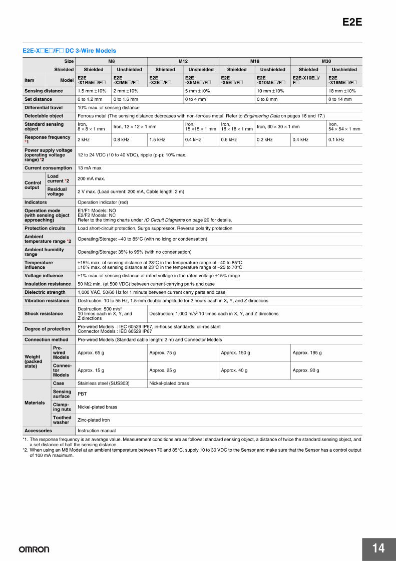
E2E-X@E@/F@ DC 3-Wire Models
*1. The response frequency is an average value. Measurement conditions are as follows: standard sensing object, a distance of twice the standard sensing object, and a set distance of half the sensing distance.
*2. When using an M8 Model at an ambient temperature between 70 and 85°C, supply 10 to 30 VDC to the Sensor and make sure that the Sensor has a control output of 100 mA maximum.
Size M8 M12 M18 M30
Shielded Shielded Unshielded Shielded Unshielded Shielded Unshielded Shielded Unshielded
Item Model E2E-X1R5E@/F@
E2E-X2ME@/F@
E2E-X2E@/F@
E2E-X5ME@/F@
E2E-X5E@/F@
E2E-X10ME@/F@
E2E-X10E@/F@
E2E-X18ME@/F@
Sensing distance 1.5 mm ±10% 2 mm ±10% 5 mm ±10% 10 mm ±10% 18 mm ±10%
Set distance 0 to 1.2 mm 0 to 1.6 mm 0 to 4 mm 0 to 8 mm 0 to 14 mm
Differential travel 10% max. of sensing distance
Detectable object Ferrous metal (The sensing distance decreases with non-ferrous metal. Refer to Engineering Data on pages 16 and 17.)
Standard sensing object
Iron, 8 × 8 × 1 mm Iron, 12 × 12 × 1 mm Iron,
15 ×15 × 1 mmIron, 18 × 18 × 1 mm Iron, 30 × 30 × 1 mm Iron,
54 × 54 × 1 mm
Response frequency *1 2 kHz 0.8 kHz 1.5 kHz 0.4 kHz 0.6 kHz 0.2 kHz 0.4 kHz 0.1 kHz
Power supply voltage (operating voltage range) *2
12 to 24 VDC (10 to 40 VDC), ripple (p-p): 10% max.
Current consumption 13 mA max.
Control output
Load current *2 200 mA max.
Residual voltage 2 V max. (Load current: 200 mA, Cable length: 2 m)
Indicators Operation indicator (red)
Operation mode (with sensing object approaching)
E1/F1 Models: NOE2/F2 Models: NCRefer to the timing charts under /O Circuit Diagrams on page 20 for details.
Protection circuits Load short-circuit protection, Surge suppressor, Reverse polarity protection
Ambient temperature range *2 Operating/Storage: −40 to 85°C (with no icing or condensation)
Ambient humidity range Operating/Storage: 35% to 95% (with no condensation)
Temperature influence
±15% max. of sensing distance at 23°C in the temperature range of −40 to 85°C±10% max. of sensing distance at 23°C in the temperature range of −25 to 70°C
Voltage influence ±1% max. of sensing distance at rated voltage in the rated voltage ±15% range
Insulation resistance 50 MΩ min. (at 500 VDC) between current-carrying parts and case
Dielectric strength 1,000 VAC, 50/60 Hz for 1 minute between current carry parts and case
Vibration resistance Destruction: 10 to 55 Hz, 1.5-mm double amplitude for 2 hours each in X, Y, and Z directions
Shock resistanceDestruction: 500 m/s2
10 times each in X, Y, and Z directions
Destruction: 1,000 m/s2 10 times each in X, Y, and Z directions
Degree of protection Pre-wired Models : IEC 60529 IP67, in-house standards: oil-resistantConnector Models : IEC 60529 IP67
Connection method Pre-wired Models (Standard cable length: 2 m) and Connector Models
Weight(packed state)
Pre-wired Models
Approx. 65 g Approx. 75 g Approx. 150 g Approx. 195 g
Connec-tor Models
Approx. 15 g Approx. 25 g Approx. 40 g Approx. 90 g
Materials
Case Stainless steel (SUS303) Nickel-plated brass
Sensing surface PBT
Clamp-ing nuts Nickel-plated brass
Toothed washer Zinc-plated iron
Accessories Instruction manual

E2E
15
E2E-C@C/B@ and E2E-X1C/B@ DC 3-Wire Models
* The response frequency is an average value. Measurement conditions are as follows: standard sensing object, a distance of twice the standard sensing object, and a set distance of half the sensing distance.
Size 3 dia. 4 dia. M5 5.4 dia.
Shielded Shielded
Item Model E2E-CR6C/B@ E2E-CR8C/B@ E2E-X1C/B@ E2E-C1C/B@
Sensing distance 0.6 mm ±15% 0.8 mm ±15% 1 mm ±15%
Set distance 0 to 0.4 mm 0 to 0.5 mm 0 to 0.7 mm
Differential travel 15% max. of sensing distance
Detectable object Ferrous metal (The sensing distance decreases with non-ferrous metal. Refer to Engineering Data on pages 17 and 18.)
Standard sensing ob-ject Iron, 3 × 3 × 1 mm Iron, 5 × 5 × 1 mm
Response frequency * 2 kHz 3 kHz
Power supply voltage (operating voltage range)
12 to 24 VDC (10 to 30 VDC), ripple (p-p): 10% max.
Current consumption 10 mA max. 17 mA max.
Control output
Load current
Open-collector output, 80 mA max. (30 VDC max.) Open-collector output, 100 mA max. (30 VDC max.)
Residual voltage
1 V max. (Load current: 80 mA, Cable length: 2 m)
2 V max. (Load current: 100 mA, Cable length: 2 m)
Indicators Operation indicator (red)
Operation mode (with sensing object approaching)
C1/B1 Models: NOC2 Models: NC
Protection circuits Reverse polarity protection, Surge suppressor
Ambient temperature range Operating/Storage: −25 to 70°C (with no icing or condensation)
Ambient humidity range Operating/Storage: 35% to 95% (with no condensation)
Temperature influ-ence ±15% max. of sensing distance at 23°C in the temperature range of −25 to 70°C
Voltage influence±5% max. of sensing distance at rated voltage in the rated voltage ±10% range
±2.5% max. of sensing distance at rated voltage in the rated voltage ±15% range
Insulation resistance 50 MΩ min. (at 500 VDC) between current-carrying parts and case
Dielectric strength 500 VAC, 50/60 Hz for 1 min between current-carrying parts and case
Vibration resistance Destruction: 10 to 55 Hz, 1.5-mm double amplitude for 2 hours each in X, Y, and Z directions
Shock resistance Destruction: 500 m/s2 10 times each in X, Y, and Z directions
Degree of protection IEC 60529 IP66 IEC 60529 IP67, in-house standards: oil-resistant
Connection method Pre-wired Models (Standard cable length: 2 m)
Weight (packed state) Approx. 60 g
Materials
Case Stainless steel (SUS303) Nickel-plated brass
Sensing surface Heat-resistant ABS
Clamping nuts Nickel-plated brass (E2E-X1C/B@ only)
Toothed washer Zinc-plated iron (E2E-X1C/B@ only)
Accessories Instruction manual
Refer to the timing charts under I/O Circuit Diagrams on page 20 for details.
16
E2EEngineering Data (Reference Value)
Sensing Area
Shielded Models E2E-C@C@/-X@C@E2E-C@B1/-X@B@E2E-X@D@/-X@T1 E2E-X@E@/-X@Y@/-X@F@
Unshielded Models
E2E-X@MD@ E2E-X@ME@/-X@MY@/-X@MF@
Influence of Sensing Object Size and Material
E2E-X2D@ E2E-X3D@/-X3T1 E2E-X7D@/-X7T1
E2E-X10D@/-X10T1 E2E-X4MD@ E2E-X8MD@
XY
E2E-X10
E2E-X7
E2E-X3
E2E-X2
−20 −15 −10 −5 0 5 10 15
12
10
8
6
4
2
0
Distance Y (mm)
Dis
tanc
e X
(m
m)
E2E-X10
E2E-X1R5
E2E-X5
E2E-X2
XY
−15 −10 −5 0 5 10
12
10
8
6
4
2
0
Distance Y (mm)
Dis
tanc
e X
(m
m)
E2E-X1/E2E-C1
E2E-CR8
E2E-CR6
XY
−3.0 −2.0 −1.0 0 1.0 2.0
1.6
1.4
1.2
1.0
0.8
0.6
0.4
0.2
0
Distance Y (mm)
Dis
tanc
e X
(m
m)
XY
E2E-X20M
E2E-X14M
E2E-X8M
E2E-X4M
−30 −20 −10 0 10 20
30
25
20
15
10
5
0
Distance Y (mm)
Dis
tanc
e X
(m
m)
E2E-X18M
E2E-X10M
E2E-X5M
E2E-X2M
XY
−30 −20 −10 0 10 20
30
25
20
15
10
5
0
Distance Y (mm)
Dis
tanc
e X
(m
m)
0 5 10 15 20 25
3.0
2.5
2.0
1.5
1.0
0.5
X
d × d t = 1 mm
Side length of sensing object: d (mm)
Iron
Stainless steel (SUS304)
Brass
AluminumCopper
Dis
tanc
e X
(m
m)
0 5 10 15 20 25 30 35 40
4.0
3.5
3.0
2.5
2.0
1.5
1.0
0.5
X
d × d t = 1 mm
Side length of sensing object: d (mm)
Iron
Stainless steel (SUS304)
Brass
AluminumCopper
Dis
tanc
e X
(m
m)
0 10 20 30 40 50
8
7
6
5
4
3
2
1
X
d × d t = 1 mm
Side length of sensing object: d (mm)
Iron
Stainless steel (SUS304)
Brass
Aluminum
Copper
Dis
tanc
e X
(m
m)
0 10 20 30 40 50 60 70
12
10
8
6
4
2
X
d × d
t = 1 mm
Side length of sensing object: d (mm)
Iron
Stainless steel (SUS304)
BrassAluminumCopper
Dis
tanc
e X
(m
m)
0 10 20 30 40 50 60 70
6
5
4
3
2
1
X
d × d t = 1 mm
Brass
Copper
Side length of sensing object: d (mm)
Iron
Stainless steel (SUS304)
Aluminum
Dis
tanc
e X
(m
m)
0 10 15 20 30 40 50 60 70
12
10
8
6
4
2
X
d × d t = 1 mm
Side length of sensing object: d (mm)
Iron
Stainless steel (SUS304)
Brass
AluminumCopper
Dis
tanc
e X
(m
m)
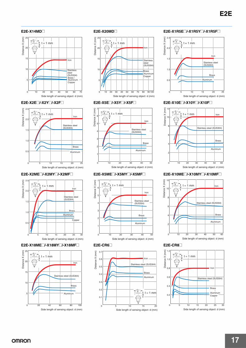
E2E
17
E2E-X14MD@ E2E-X20MD@ E2E-X1R5E@/-X1R5Y@/-X1R5F@
E2E-X2E@/-X2Y@/-X2F@ E2E-X5E@/-X5Y@/-X5F@ E2E-X10E@/-X10Y@/-X10F@
E2E-X2ME@/-X2MY@/-X2MF@ E2E-X5ME@/-X5MY@/-X5MF@ E2E-X10ME@/-X10MY@/-X10MF@
E2E-X18ME@/-X18MY@/-X18MF@ E2E-CR6@ E2E-CR8@
0 10 20 30 40 50 60 70
25
20
15
10
5
X
d × d
t = 1 mm
Side length of sensing object: d (mm)
Iron
Stainless steel (SUS304)BrassAluminumCopper
Dis
tanc
e X
(m
m)
0 10 20 30 40 50 60 70 80 90 100
25
20
15
10
5
X
d × d t = 1 mm
Side length of sensing object: d (mm)
Iron
Stainless steel (SUS304)
BrassAluminumCopper
Dis
tanc
e X
(m
m)
0 5 10 15 20 25
2.5
2.0
1.5
1.0
0.5
X
d × d
t = 1 mm
Side length of sensing object: d (mm)
Iron
Stainless steel (SUS304)
Brass
Aluminum
Dis
tanc
e X
(m
m)
0 5 10 15 20 25
2.5
2.0
1.5
1.0
0.5
X
d × d t = 1 mm
Side length of sensing object: d (mm)
Iron
Stainless steel (SUS304)
Brass
Aluminum
Dis
tanc
e X
(m
m)
0 10 20 30 40 50
7
6
5
4
3
2
1
X
d × d t = 1 mm
Side length of sensing object: d (mm)
Stainless steel (SUS304)
Iron
Brass
Aluminum
Dis
tanc
e X
(m
m)
0 10 20 30 40 50 60
12
10
8
6
4
2
X
d × d t = 1 mm
Side length of sensing object: d (mm)
Stainless steel (SUS304)
Iron
Brass
Aluminum
Dis
tanc
e X
(m
m)
0 5 10 15 20 25 30
2.5
2.0
1.5
1.0
0.5
X
d × d t = 1 mm
Side length of sensing object: d (mm)
Iron
Stainless steel (SUS304)
Brass
Aluminum
Copper
Dis
tanc
e X
(m
m)
0 10 20 30 40 50
7
6
5
4
3
2
1
X
d × d t = 1 mm
Side length of sensing object: d (mm)
Stainless steel (SUS304)
Iron
Brass
Aluminum
Dis
tanc
e X
(m
m)
0 10 20 30 40 50 60
12
10
8
6
4
2
X
Side length of sensing object: d (mm)
Stainless steel (SUS304)
Iron
Brass
Aluminum
d × d t = 1 mm
Dis
tanc
e X
(m
m)
0 20 40 60 80 100
25
20
15
10
5
X
d × d t = 1 mm
Side length of sensing object: d (mm)
Stainless steel (SUS304)
Iron
Brass
Aluminum
Dis
tanc
e X
(m
m)
0.7
0.6
0.5
0.4
0.3
0.2
0.1
0 5 10 15 20
X
d × d t = 1 mm
Side length of sensing object: d (mm)
Stainless steel (SUS304)
Iron
Brass
Aluminum
Dis
tanc
e X
(m
m)
0 5 10 15 20 25 30
1.2
1.0
0.8
0.6
0.4
0.2
X
d × d t = 1 mm
Side length of sensing object: d (mm)
Stainless steel (SUS304)
Iron
Brass
AluminumCopper
Dis
tanc
e X
(m
m)
18
E2E
E2E-X1@/-C1@
Leakage Current
E2E-X@D@ E2E-X@Y@ E2E-X@T1
Residual Output Voltage
E2E-X@D@ E2E-X@T1
E2E-X@Y@ at 24 VAC E2E-X@Y@ at 100 VAC E2E-X@Y@ at 200 VAC
0 5 10 15 20 25
1.2
1.0
0.8
0.6
0.4
0.2
X
d × d t = 1 mm
Side length of sensing object: d (mm)
Stainless steel (SUS304)
Iron
Brass
Aluminum
Dis
tanc
e X
(m
m)
0 5 10 15 20 25 30
1.0
0.8
0.6
0.4
0.2
E2E-X2D1-N
E2E-X7D1-N
E2E-X3D1-N
E2E-X10D1-N
Power supply voltage (V)
Leak
age
curr
ent (
mA
)
V
0 50 100 150 200 250 300
1.4
1.2
1.0
0.8
0.6
0.4
0.2
~mA
~
Power supply voltage (V)
AC power
Protective resistance
Proximity Sensor (OFF)
Leak
age
curr
ent (
mA
)
0 50 100 150 200 250 300
1.4
1.2
1.0
0.8
0.6
0.4
0.2
Power supply voltage (V)
AC power
DC power
Leak
age
curr
ent (
mA
)
5
4
3
2
1
01 3 5 10 30 50 100
E2E-X@D@
E2E-X@D1-M1J-T
Load current (mA)
Res
idua
l out
put v
olta
ge (
V) 6
5
4
3
2
1 3 5 10 30 50 100
24 VDC
100 VAC
200 VAC
Load current (mA)
Res
idua
l out
put v
olta
ge (
V)
V
30
25
20
15
10
5
01 3 5 10 30 50 100 300 500
VL
~
~A24 VAC
OFF
ONLoad
vol
tage
VL
(V)
Load current (mA)
Residual load voltage
Residual output voltageV
120
100
80
60
40
20
01 3 5 10 30 50 100 300 500
100 VACVL
~
~A
OFF
ON
Load current (mA)
Residual output voltage
Residual load voltage
Load
vol
tage
VL
(V)
V
200 VACVL
~A
240
200
160
120
80
40
0
~
ON
1 3 5 10 30 50 100 300 500
OFF
Load current (mA)
Residual output voltage
Residual load voltage
Load
vol
tage
VL
(V)
E2E
19
I/O Circuit Diagrams
E2E-X@D@ DC 2-Wire ModelsOperation
mode Model Timing Chart Output circuit
Without self-
diagnostic output:
NO
E2E-X@D1-NE2E-X@D1-M1G(J)E2E-X@D1-(M1TGJ)-UE2E-X@D1-M3G
E2E-X@D1-M1J-T
Without self-
diagnostic output:
NC
E2E-X@D2-NE2E-X@D2-M1GE2E-X@D2-(M1TGJ)-UE2E-X@D2-M3G
With self-diagnostic
output: NO
E2E-X@D1SE2E-X@D1S-M1
(%) 80 0100
Sensing object
Rated sensing distance
Stable sensing areaNon-sensing
area
Unstable sensing area
Set position
Proximity Sensor
ON
OFF
ON
OFF
ON
OFF
Setting indicator (green)
Operation indicator (red)
Control output
0 V
+V
4
1Load
Brown
Blue
Polarity: Yes
Note: The load can be connected to either the +V or 0 V side.
Prox-imity Sensor main circuit
0 V(+V)
+V(0 V)
3
4Load
Prox-imity Sensor main circuit
Polarity: None
Note 1. The load can be connected to either the +V or 0 V side.
2. The E2E-X@D1-M1J-T has no polarity. Therefore, terminals 3 and 4 have no polarity.
0(%) 100
Sensing object
Rated sensing distance
Sensing areaNon-sensing
area
Proximity Sensor
ON
OFF
ON
OFF
Operation indicator (red)
Control output
0 V
+V
2
1Load
Brown
Blue
Note: The load can be connected to either the +V or 0 V side.
Prox-imity Sensor main circuit
(%) 80 0100
Sensing object
Rated sensing distance
Stable sensing areaNon-sensing
area
Unstable sensing area
Set position
Proximity Sensor
ON
OFF
ON
OFF
ON
OFF
ON
OFF
Setting indicator (green)
Operation indicator (red)
Control output
Diagnostic output*
* The diagnostic output is ON when there is a coil burnout or the sensing object is located in the unstable sensing area for 0.3 s or longer.
+V
+V
0
Load
Load
Brown (4)
Orange (2) (diagnostic output)
Blue (3)
Note: Connect both the loads to the +V side of the control output and diagnostic output.
Prox-imity Sensor main circuit
20
E2E
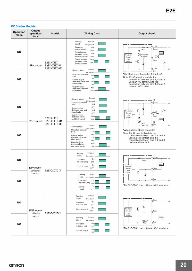
DC 3-Wire Models
Operation mode
Output specifica-
tionsModel Timing Chart Output circuit
NO
NPN outputE2E-X@E@E2E-X@E@-M1E2E-X@E@-M3
NC
NO
PNP outputE2E-X@F@E2E-X@F@-M1E2E-X@F@-M3
NC
NO
NPN open-collector output
E2E-C/X@C@
NC
NO
PNP open-collector output
E2E-C/X@B@
NC
Present
Not present
ON
OFF
ON
OFF
High
Low
Operation indicator (red)
Sensing object
Control output (between brown and black leads)
Output voltage (between black and blue leads)
+V
Tr
0 V
100 Ω
3
4
1
Load
Brown
Black
*Constant current output is 1.5 to 3 mA.Blue
Constant current*
Proximity Sensor
main circuit
Note: For Connector Models, the connection between pins 1, 4 and 3 uses an NO contact, and the connection between pins 1, 2 and 3 uses an NC contact.
2
Present
Not present
ON
OFF
ON
OFF
High
Low
Operation indicator (red)
Sensing object
Control output (between brown and black leads)
Output voltage (between black and blue leads)
Present
Not present
ON
OFF
ON
OFF
High
Low
Operation indicator (red)
Sensing object
Control output (Between blue and black leads)
Output voltage (between brown and black leads)
100 Ω
Tr
+V
*
Load
Brown
Black
*When a transistor is connected
Blue
Proximity Sensor
main circuit
Note: For Connector Models, the connection between pins 1, 4 and 3 uses an NO contact, and the connection between pins 1, 2 and 3 uses an NC contact.
0 V
3
4
1
2
Present
Not present
ON
OFF
ON
OFF
High
Low
Operation indicator (red)
Sensing object
Control output (Between blue and black leads)
Output voltage (between brown and black leads)
Present
Not present
ON
OFF
ON
OFF
Operation indicator (red)
Sensing object
Control output
+V100 Ω *
0 V
Load
Brown
Black
Blue
Proximity Sensor
main circuit
*The E2E-CR6@ does not have 100-Ω resistance.
Present
Not present
ON
OFF
ON
OFF
Operation indicator (red)
Sensing object
Control output
Present
Not present
ON
OFF
ON
OFF
Operation indicator (red)
Sensing object
Control output
0 V
+V
100 Ω *
Load
Brown
Black
Blue
Proximity Sensor
main circuit
*The E2E-CR6@ does not have 100-Ω resistance.
Present
Not present
ON
OFF
ON
OFF
Operation indicator (red)
Sensing object
Control output
E2E
21
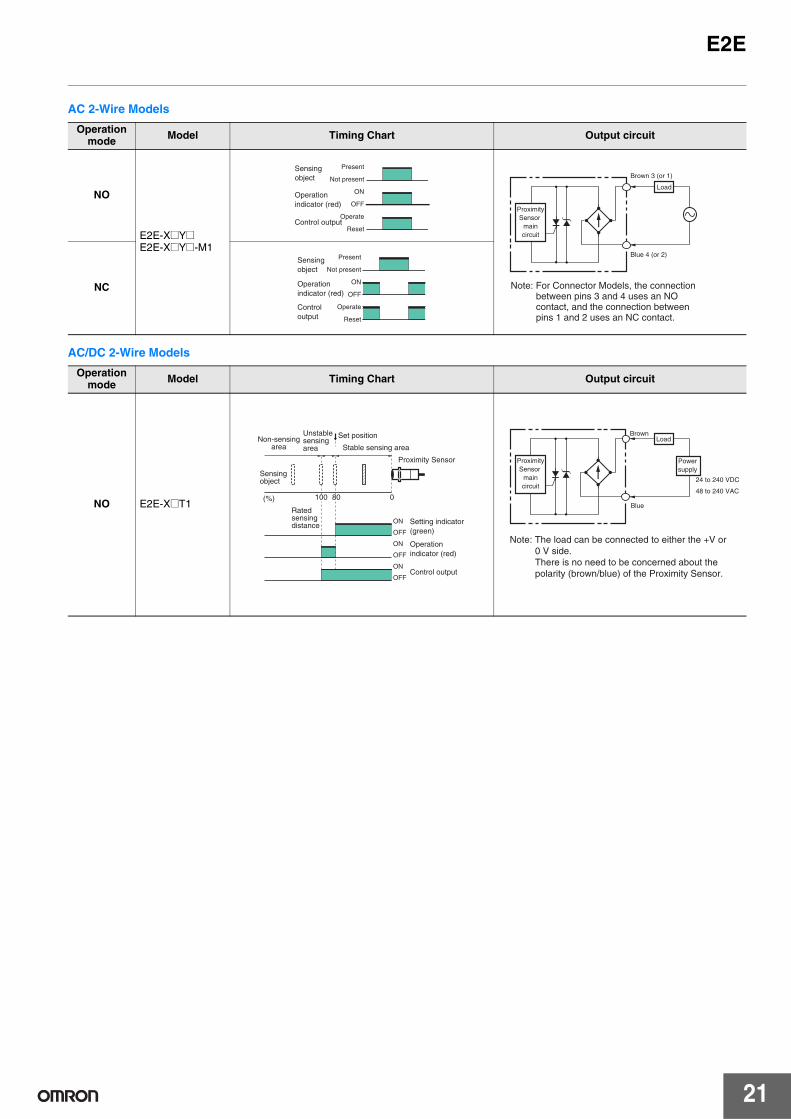
AC 2-Wire Models
AC/DC 2-Wire Models
Operation mode Model Timing Chart Output circuit
NO
E2E-X@Y@E2E-X@Y@-M1
NC
Operation mode Model Timing Chart Output circuit
NO E2E-X@T1
Present
Not present
ON
OFF
Operate
Reset
Operation indicator (red)
Sensing object
Control output
Load
Brown 3 (or 1)
Blue 4 (or 2)
Proximity Sensor
main circuit
Note: For Connector Models, the connection between pins 3 and 4 uses an NO contact, and the connection between pins 1 and 2 uses an NC contact.
Present
Not present
ON
OFF
Operate
Reset
Operation indicator (red)
Sensing object
Control output
80100 0(%)
Sensing object
Rated sensing distance
Stable sensing areaNon-sensing
area
Unstable sensing area
Set position
Proximity Sensor
ON
OFF
ON
OFF
ON
OFF
Setting indicator (green)
Operation indicator (red)
Control output
24 to 240 VDC
48 to 240 VAC
LoadBrown
Blue
Proximity Sensor
main circuit
Power supply
Note: The load can be connected to either the +V or 0 V side. There is no need to be concerned about the polarity (brown/blue) of the Proximity Sensor.
22
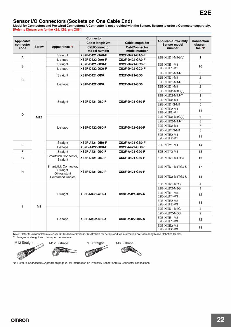
E2ESensor I/O Connectors (Sockets on One Cable End)Model for Connectors and Pre-wired Connectors: A Connector is not provided with the Sensor. Be sure to order a Connector separately. [Refer to Dimensions for the XS2, XS3, and XS5.]
Note: Refer to Introduction to Sensor I/O Connectors/Sensor Controllers for details and for information on Cable length and Robotics Cables. *1. Images of straight and L-shaped connectors.
*2. Refer to Connection Diagrams on page 23 for information on Proximity Sensor and I/O Connector connections.
Applicable connector
code
ConnectorApplicable Proximity
Sensor model number
Connection diagram No. *2Screw Appearance *1
Cable length 2m Cable length 5mCablConnector model number
CablConnector model number
A
M12
Straight XS2F-D421-DA0-F XS2F-D421-GA0-FE2E-X@D1-M1G(J) 1
L-shape XS2F-D422-DA0-F XS2F-D422-GA0-F
BStraight XS2F-D421-DC0-F XS2F-D421-GC0-F E2E-X@E1-M1
E2E-X@F1-M1 10L-shape XS2F-D422-DC0-F XS2F-D422-GC0-F
CStraight XS2F-D421-DD0 XS2F-D421-GD0
E2E-X@D1-M1J-T 3E2E-X@D1-M1 2
L-shape XS2F-D422-DD0 XS2F-D422-GD0E2E-X@D1-M1J-T 3E2E-X@D1-M1 2
D
Straight XS2F-D421-D80-F XS2F-D421-G80-F
E2E-X@D2-M1G(J) 6E2E-X@D2-M1J-T 8E2E-X@D2-M1 7E2E-X@D1S-M1 5E2E-X@E2-M1E2E-X@F2-M1 11
L-shape XS2F-D422-D80-F XS2F-D422-G80-F
E2E-X@D2-M1G(J) 6E2E-X@D2-M1J-T 8E2E-X@D2-M1 7E2E-X@D1S-M1 5E2E-X@E2-M1E2E-X@F2-M1 11
EStraight XS2F-A421-DB0-F XS2F-A421-GB0-F
E2E-X@Y1-M1 14L-shape XS2F-A422-DB0-F XS2F-A422-GB0-F
F Straight XS2F-A421-D90-F XS2F-A421-G90-F E2E-X@Y2-M1 15
G Smartclick Connector,Straight XS5F-D421-D80-F XS5F-D421-G80-F E2E-X@D1-M1TGJ 16
H
Smartclick Connector,Straight
Oil-resistant Reinforced Cables
XS5F-D421-D80-P XS5F-D421-G80-P
E2E-X@D1-M1TGJ-U 17
E2E-X@D2-M1TGJ-U 18
I M8
Straight XS3F-M421-402-A XS3F-M421-405-A
E2E-X@D1-M3G 4E2E-X@D2-M3G 9E2E-X@E1-M3E2E-X@F1-M3 12
E2E-X@E2-M3E2E-X@F2-M3 13
L-shape XS3F-M422-402-A XS3F-M422-405-A
E2E-X@D1-M3G 4E2E-X@D2-M3G 9E2E-X@E1-M3E2E-X@F1-M3 12
E2E-X@E2-M3E2E-X@F2-M3 13
M12 Straight M12 L-shape M8 Straight M8 L-shape
E2E
23
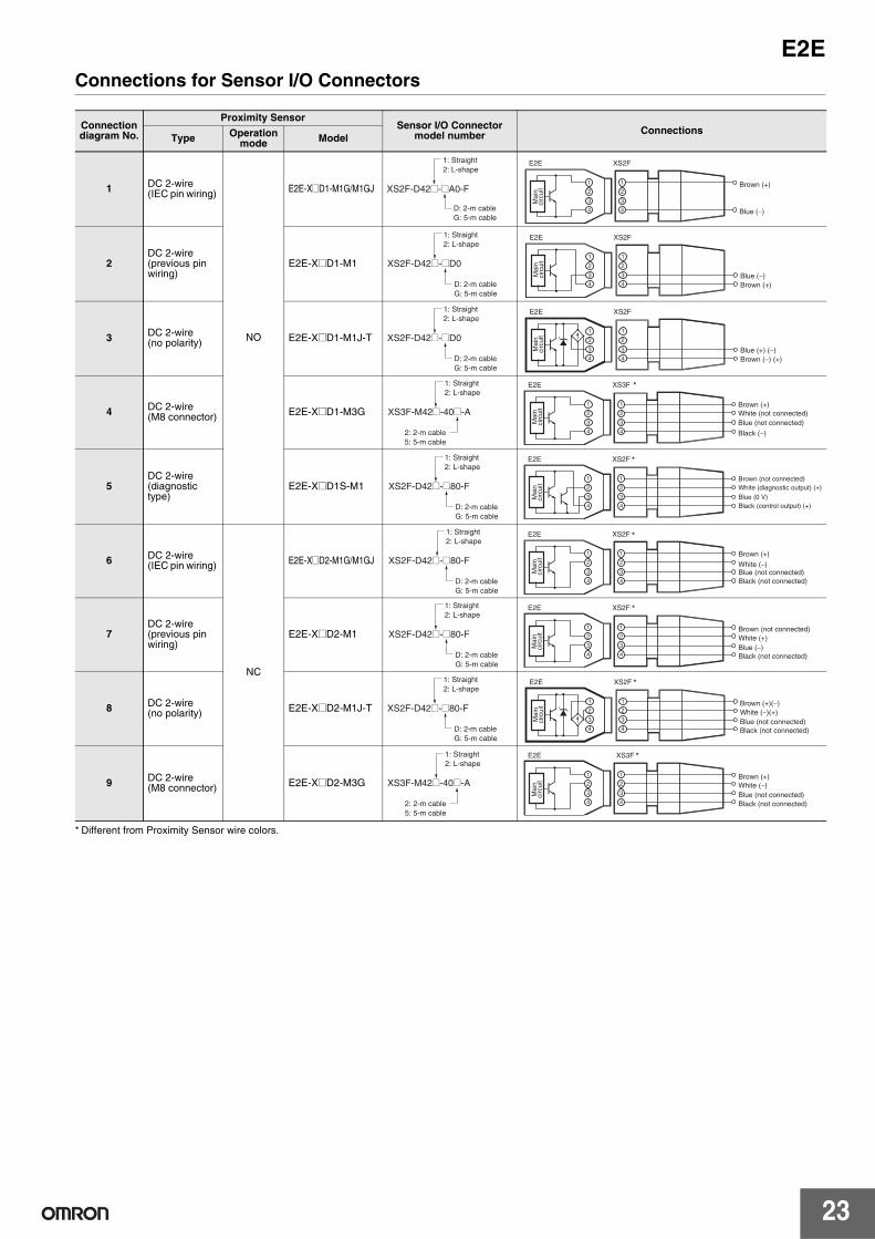
Connections for Sensor I/O Connectors
* Different from Proximity Sensor wire colors.
Connection diagram No.
Proximity SensorSensor I/O Connector
model number ConnectionsType Operation
mode Model
1 DC 2-wire (IEC pin wiring)
NO
E2E-X@D1-M1G/M1GJ
2DC 2-wire (previous pin wiring)
E2E-X@D1-M1
3 DC 2-wire (no polarity) E2E-X@D1-M1J-T
4 DC 2-wire (M8 connector) E2E-X@D1-M3G
5DC 2-wire (diagnostic type)
E2E-X@D1S-M1
6 DC 2-wire (IEC pin wiring)
NC
E2E-X@D2-M1G/M1GJ
7DC 2-wire (previous pin wiring)
E2E-X@D2-M1
8 DC 2-wire (no polarity) E2E-X@D2-M1J-T
9 DC 2-wire (M8 connector) E2E-X@D2-M3G
XS2F-D42@-@A0-F
1: Straight 2: L-shape
D: 2-m cable G: 5-m cable
4
3
2
1
4
3
2
1
XS2FE2E
Mai
n ci
rcui
t Brown (+)
Blue (−)
XS2F-D42@-@D0
1: Straight 2: L-shape
D: 2-m cable G: 5-m cable
2
4
3
2
1
4
3
1
XS2FE2E
Blue (−)Brown (+)
Mai
n ci
rcui
t
XS2F-D42@-@D0
1: Straight 2: L-shape
D: 2-m cable G: 5-m cable
4
3
2
1
4
3
2
1
E2E
Mai
n ci
rcui
t
XS2F
Blue (+) (−)Brown (−) (+)
XS3F-M42@-40@-A
1: Straight 2: L-shape
2: 2-m cable 5: 5-m cable
*XS3F
4
3
2
1
4
3
2
1
E2E
Brown (+)White (not connected) Blue (not connected)
Black (−)
Mai
n ci
rcui
t
XS2F-D42@-@80-F
1: Straight 2: L-shape
D: 2-m cable G: 5-m cable
*XS2F
4
3
2
1
4
3
2
1
E2E
Brown (not connected) White (diagnostic output) (+)Blue (0 V)Black (control output) (+)
Mai
n ci
rcui
t
XS2F-D42@-@80-F
1: Straight 2: L-shape
D: 2-m cable G: 5-m cable
*XS2F
4
3
2
1
4
3
2
1
E2E
White (−)Blue (not connected)
Brown (+)
Black (not connected)
Mai
n ci
rcui
t
XS2F-D42@-@80-F
1: Straight 2: L-shape
D: 2-m cable G: 5-m cable
*XS2F
4
3
2
1
4
3
2
1
E2E
White (+)Blue (−)
Brown (not connected)
Black (not connected)
Mai
n ci
rcui
t
XS2F-D42@-@80-F
1: Straight 2: L-shape
D: 2-m cable G: 5-m cable
*XS2F
4
3
2
1
4
3
2
1
E2E
Mai
n ci
rcui
t
White (−)(+)Blue (not connected)
Brown (+)(−)
Black (not connected)
XS3F-M42@-40@-A
1: Straight 2: L-shape
2: 2-m cable 5: 5-m cable
*XS3F
4
3
2
1
4
3
2
1
E2E
White (−)Blue (not connected)
Brown (+)
Black (not connected)
Mai
n ci
rcui
t
24
E2E
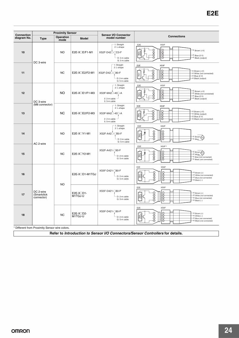
* Different from Proximity Sensor wire colors.
Connection diagram No.
Proximity SensorSensor I/O Connector
model number ConnectionsType Operation
mode Model
10
DC 3-wire
NO E2E-X@E/F1-M1
11 NC E2E-X@E2/F2-M1
12
DC 3-wire (M8 connector)
NO E2E-X@E1/F1-M3
13 NC E2E-X@E2/F2-M3
14
AC 2-wire
NO E2E-X@Y1-M1
15 NC E2E-X@Y2-M1
16
DC 2-wire(Smartclick connector)
NO
E2E-X@D1-M1TGJ
17 E2E-X@D1-M1TGJ-U
18 NC E2E-X@D2-M1TGJ-U
Refer to Introduction to Sensor I/O Connectors/Sensor Controllers for details.
XS2F-D42@-@C0-F
1: Straight 2: L-shape
D: 2-m cable G: 5-m cable
XS2F
4
3
2
1
4
3
2
1
E2E
Brown (+V)
Blue (0 V)Black (output)
Mai
n ci
rcui
t
XS2F-D42@-@80-F
1: Straight 2: L-shape
D: 2-m cable G: 5-m cable
XS3F
4
3
2
1
4
3
2
1
E2E
Brown (+V)White (not connected) Blue (0 V)Black (output)
Mai
n
XS3F-M42@-40@-A
1: Straight 2: L-shape
2: 2-m cable 5: 5-m cable
XS3F
4
3
2
1
4
3
2
1
E2E
Brown (+V)White (not connected) Blue (0 V)Black (output)
Mai
n ci
rcui
t
XS3F-M42@-40@-A
1: Straight 2: L-shape
2: 2-m cable 5: 5-m cable
XS3F
4
3
2
1
4
3
2
1
E2E
Brown (+V)White (output) Blue (0 V)Black (not connected)
Mai
n ci
rcui
t
XS2F-A42@-@B0-F
1: Straight 2: L-shape
D: 2-m cable G: 5-m cable
XS2F
4
3
2
1
4
3
2
1
E2E
BrownBlue
Mai
n ci
rcui
t
XS2F-A421-@90-F
D: 2-m cable G: 5-m cable
*XS2F
4
3
2
1
4
3
2
1
E2E
Blue (not connected) Black (not connected)
BrownWhite
Mai
n ci
rcui
t
XS5F-D421-@80-F
D: 2-m cable G: 5-m cable
XS5F
4
3
2
1
4
3
2
1
E2E
Blue (not connected) Black (−)
Brown (+)White (not connected)
Mai
n ci
rcui
t
XS5F-D421-@80-P
D: 2-m cable G: 5-m cable
XS5F
4
3
2
1
4
3
2
1
E2E
Blue (not connected) Black (−)
Brown (+)White (not connected)
Mai
n ci
rcui
t
XS5F-D421-@80-P
D: 2-m cable G: 5-m cable
XS5F
4
3
2
1
4
3
2
1
E2E
Blue (not connected) Black (not connected)
Brown (+) White (−)
Mai
n ci
rcui
t
E2E
25
Safety Precautions
Refer to Warranty and Limitations of Liability.
This product is not designed or rated for ensuring safety of persons either directly or indirectly.Do not use it for such purposes.
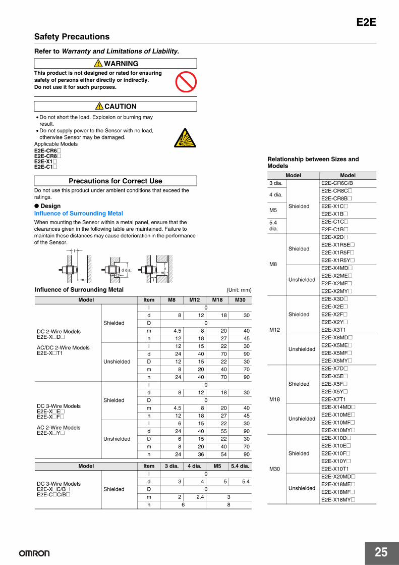
Do not use this product under ambient conditions that exceed the ratings.
● DesignInfluence of Surrounding MetalWhen mounting the Sensor within a metal panel, ensure that the clearances given in the following table are maintained. Failure to maintain these distances may cause deterioration in the performance of the Sensor.
WARNING
CAUTION• Do not short the load. Explosion or burning may
result. • Do not supply power to the Sensor with no load,
otherwise Sensor may be damaged. Applicable Models E2E-CR6@E2E-CR8@E2E-X1@E2E-C1@
Precautions for Correct Use
l
mn
mD
d dia.
l
Influence of Surrounding Metal (Unit: mm)
Model Item M8 M12 M18 M30
DC 2-Wire ModelsE2E-X@D@
AC/DC 2-Wire ModelsE2E-X@T1
Shielded
l 0d 8 12 18 30D 0m 4.5 8 20 40n 12 18 27 45
Unshielded
l 12 15 22 30d 24 40 70 90D 12 15 22 30m 8 20 40 70n 24 40 70 90
DC 3-Wire ModelsE2E-X@E@E2E-X@F@
AC 2-Wire ModelsE2E-X@Y@
Shielded
l 0d 8 12 18 30D 0m 4.5 8 20 40n 12 18 27 45
Unshielded
l 6 15 22 30d 24 40 55 90D 6 15 22 30m 8 20 40 70n 24 36 54 90
Model Item 3 dia. 4 dia. M5 5.4 dia.
DC 3-Wire ModelsE2E-X@C/B@E2E-C@C/B@
Shielded
l 0d 3 4 5 5.4D 0m 2 2.4 3n 6 8
Relationship between Sizes and Models
Model Model3 dia.
Shielded
E2E-CR6C/B
4 dia.E2E-CR8C@E2E-CR8B@
M5E2E-X1C@E2E-X1B@
5.4 dia.
E2E-C1C@E2E-C1B@
M8
Shielded
E2E-X2D@E2E-X1R5E@E2E-X1R5F@E2E-X1R5Y@
Unshielded
E2E-X4MD@E2E-X2ME@E2E-X2MF@E2E-X2MY@
M12
Shielded
E2E-X3D@E2E-X2E@E2E-X2F@E2E-X2Y@E2E-X3T1
Unshielded
E2E-X8MD@E2E-X5ME@E2E-X5MF@E2E-X5MY@
M18
Shielded
E2E-X7D@E2E-X5E@E2E-X5F@E2E-X5Y@E2E-X7T1
Unshielded
E2E-X14MD@E2E-X10ME@E2E-X10MF@E2E-X10MY@
M30
Shielded
E2E-X10D@E2E-X10E@E2E-X10F@E2E-X10Y@E2E-X10T1
Unshielded
E2E-X20MD@E2E-X18ME@E2E-X18MF@E2E-X18MY@
26
E2E
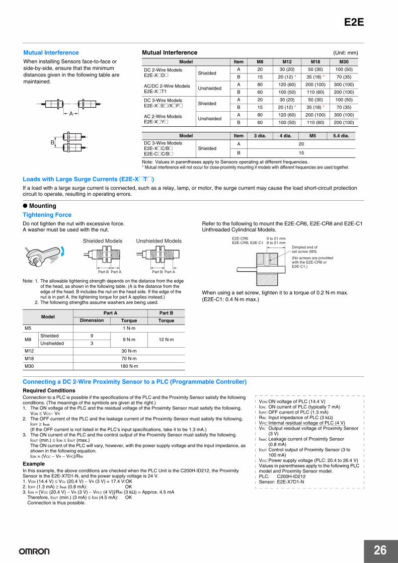
Loads with Large Surge Currents (E2E-X@T@)If a load with a large surge current is connected, such as a relay, lamp, or motor, the surge current may cause the load short-circuit protection circuit to operate, resulting in operating errors.
● Mounting
Tightening ForceDo not tighten the nut with excessive force. A washer must be used with the nut.
Note: 1. The allowable tightening strength depends on the distance from the edge of the head, as shown in the following table. (A is the distance from the edge of the head. B includes the nut on the head side. If the edge of the nut is in part A, the tightening torque for part A applies instead.)
2. The following strengths assume washers are being used.
Refer to the following to mount the E2E-CR6, E2E-CR8 and E2E-C1 Unthreaded Cylindrical Models.
When using a set screw, tighten it to a torque of 0.2 N·m max.(E2E-C1: 0.4 N·m max.)
Connecting a DC 2-Wire Proximity Sensor to a PLC (Programmable Controller)Required ConditionsConnection to a PLC is possible if the specifications of the PLC and the Proximity Sensor satisfy the following conditions. (The meanings of the symbols are given at the right.)1. The ON voltage of the PLC and the residual voltage of the Proximity Sensor must satisfy the following.
VON ≤ VCC− VR
2. The OFF current of the PLC and the leakage current of the Proximity Sensor must satisfy the following. IOFF ≥ Ileak
(If the OFF current is not listed in the PLC’s input specifications, take it to be 1.3 mA.) 3. The ON current of the PLC and the control output of the Proximity Sensor must satisfy the following.
IOUT (min.) ≤ ION ≤ IOUT (max.)The ON current of the PLC will vary, however, with the power supply voltage and the input impedance, as shown in the following equation. ION = (VCC − VR − VPC)/RIN
ExampleIn this example, the above conditions are checked when the PLC Unit is the C200H-ID212, the Proximity Sensor is the E2E-X7D1-N, and the power supply voltage is 24 V. 1. VON (14.4 V) ≤ VCc (20.4 V) − VR (3 V) = 17.4 V:OK2. IOFF (1.3 mA) ≥ Ileak (0.8 mA): OK3. ION = [VCC (20.4 V) − VR (3 V) − VPLC (4 V)]/RIN (3 kΩ) = Approx. 4.5 mA
Therefore, IOUT (min.) (3 mA) ≤ ION (4.5 mA): OKConnection is thus possible.
Mutual Interference (Unit: mm)
Note: Values in parentheses apply to Sensors operating at different frequencies.* Mutual interference will not occur for close-proximity mounting if models with different frequencies are used together.
Model Item M8 M12 M18 M30
DC 2-Wire ModelsE2E-X@D@
AC/DC 2-Wire ModelsE2E-X@T1
ShieldedA 20 30 (20) 50 (30) 100 (50)
B 15 20 (12) * 35 (18) * 70 (35)
UnshieldedA 80 120 (60) 200 (100) 300 (100)
B 60 100 (50) 110 (60) 200 (100)
DC 3-Wire ModelsE2E-X@E@/X@F@
AC 2-Wire ModelsE2E-X@Y@
ShieldedA 20 30 (20) 50 (30) 100 (50)
B 15 20 (12) * 35 (18) * 70 (35)
UnshieldedA 80 120 (60) 200 (100) 300 (100)
B 60 100 (50) 110 (60) 200 (100)
Model Item 3 dia. 4 dia. M5 5.4 dia.
DC 3-Wire ModelsE2E-X@C/B@E2E-C@C/B@
ShieldedA 20
B 15
Mutual InterferenceWhen installing Sensors face-to-face or side-by-side, ensure that the minimum distances given in the following table are maintained.
A
B
ModelPart A Part B
Dimension Torque Torque
M5 1 N·m
M8Shielded 9
9 N·m 12 N·mUnshielded 3
M12 30 N·m
M18 70 N·m
M30 180 N·m
Part B Part A Part B Part A
Shielded Models Unshielded Models 8 to 21 mm9 to 21 mm
E2E-CR8, E2E-C1E2E-CR6
Dimpled end of set screw (M3)
(No screws are provided with the E2E-CR8 or E2E-C1.)
VON:ON voltage of PLC (14.4 V)ION: ON current of PLC (typically 7 mA)IOFF: OFF current of PLC (1.3 mA)RIN: Input impedance of PLC (3 kΩ) VPC: Internal residual voltage of PLC (4 V)VR: Output residual voltage of Proximity Sensor
(3 V)Ileak: Leakage current of Proximity Sensor
(0.8 mA)IOUT Control output of Proximity Sensor (3 to
100 mA)VCC: Power supply voltage (PLC: 20.4 to 26.4 V)Values in parentheses apply to the following PLC model and Proximity Sensor model. PLC: C200H-ID212Sensor: E2E-X7D1-N
E2E
27
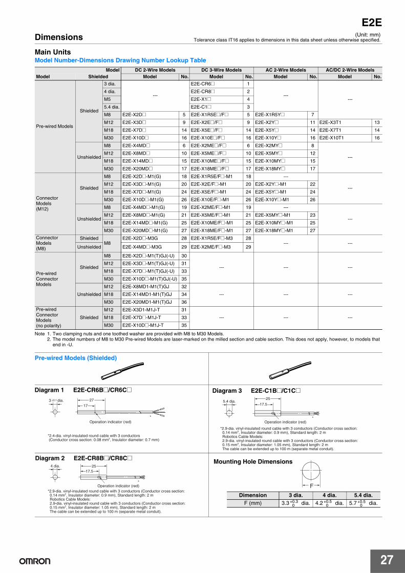
Dimensions
Main UnitsModel Number-Dimensions Drawing Number Lookup Table
Note 1. Two clamping nuts and one toothed washer are provided with M8 to M30 Models. 2. The model numbers of M8 to M30 Pre-wired Models are laser-marked on the milled section and cable section. This does not apply, however, to models that
end in -U.
Model DC 2-Wire Models DC 3-Wire Models AC 2-Wire Models AC/DC 2-Wire ModelsModel Shielded Model No. Model No. Model No. Model No.
Pre-wired Models
Shielded
3 dia.
---
E2E-CR6@ 1
------
4 dia. E2E-CR8@ 2
M5 E2E-X1@ 4
5.4 dia. E2E-C1@ 3
M8 E2E-X2D@ 5 E2E-X1R5E@/F@ 5 E2E-X1R5Y@ 7
M12 E2E-X3D@ 9 E2E-X2E@/F@ 9 E2E-X2Y@ 11 E2E-X3T1 13
M18 E2E-X7D@ 14 E2E-X5E@/F@ 14 E2E-X5Y@ 14 E2E-X7T1 14
M30 E2E-X10D@ 16 E2E-X10E@/F@ 16 E2E-X10Y@ 16 E2E-X10T1 16
Unshielded
M8 E2E-X4MD@ 6 E2E-X2ME@/F@ 6 E2E-X2MY@ 8
---M12 E2E-X8MD@ 10 E2E-X5ME@/F@ 10 E2E-X5MY@ 12
M18 E2E-X14MD@ 15 E2E-X10ME@/F@ 15 E2E-X10MY@ 15
M30 E2E-X20MD@ 17 E2E-X18ME@/F@ 17 E2E-X18MY@ 17
Connector Models(M12)
Shielded
M8 E2E-X2D@-M1(G) 18 E2E-X1R5E/F@-M1 18 ---
---M12 E2E-X3D@-M1(G) 20 E2E-X2E/F@-M1 20 E2E-X2Y@-M1 22
M18 E2E-X7D@-M1(G) 24 E2E-X5E/F@-M1 24 E2E-X5Y@-M1 24
M30 E2E-X10D@-M1(G) 26 E2E-X10E/F@-M1 26 E2E-X10Y@-M1 26
Unshielded
M8 E2E-X4MD@-M1(G) 19 E2E-X2ME/F@-M1 19 ---
---M12 E2E-X8MD@-M1(G) 21 E2E-X5ME/F@-M1 21 E2E-X5MY@-M1 23
M18 E2E-X14MD@-M1(G) 25 E2E-X10ME/F@-M1 25 E2E-X10MY@-M1 25
M30 E2E-X20MD@-M1(G) 27 E2E-X18ME/F@-M1 27 E2E-X18MY@-M1 27
Connector Models(M8)
ShieldedM8
E2E-X2D@-M3G 28 E2E-X1R5E/F@-M3 28--- ---
Unshielded E2E-X4MD@-M3G 29 E2E-X2ME/F@-M3 29
Pre-wired Connector Models
Shielded
M8 E2E-X2D@-M1(T)GJ(-U) 30
--- --- ---M12 E2E-X3D@-M1(T)GJ(-U) 31
M18 E2E-X7D@-M1(T)GJ(-U) 33
M30 E2E-X10D@-M1(T)GJ(-U) 35
Unshielded
M12 E2E-X8MD1-M1(T)GJ 32
--- --- ---M18 E2E-X14MD1-M1(T)GJ 34
M30 E2E-X20MD1-M1(T)GJ 36
Pre-wired Connector Models(no polarity)
Shielded
M12 E2E-X3D1-M1J-T 31
--- --- ---M18 E2E-X7D@-M1J-T 33
M30 E2E-X10D@-M1J-T 35
(Unit: mm)Tolerance class IT16 applies to dimensions in this data sheet unless otherwise specified.
Pre-wired Models (Shielded)
3 dia.
Operation indicator (red)
±0.1
*
17
27
*2.4-dia. vinyl-insulated round cable with 3 conductors (Conductor cross section: 0.08 mm2, Insulator diameter: 0.7 mm)
Diagram 1 E2E-CR6B@/CR6C@ Diagram 3 E2E-C1B@/C1C@
17.5
255.4 dia.
*Operation indicator (red)
*2.9-dia. vinyl-insulated round cable with 3 conductors (Conductor cross section: 0.14 mm2, Insulator diameter: 0.9 mm), Standard length: 2 m Robotics Cable Models: 2.9-dia. vinyl-insulated round cable with 3 conductors (Conductor cross section: 0.15 mm2, Insulator diameter: 1.05 mm), Standard length: 2 m The cable can be extended up to 100 m (separate metal conduit).
Diagram 2 E2E-CR8B@/CR8C@
17.5254 dia.
*Operation indicator (red)
*2.9-dia. vinyl-insulated round cable with 3 conductors (Conductor cross section: 0.14 mm2, Insulator diameter: 0.9 mm), Standard length: 2 m Robotics Cable Models: 2.9-dia. vinyl-insulated round cable with 3 conductors (Conductor cross section: 0.15 mm2, Insulator diameter: 1.05 mm), Standard length: 2 m The cable can be extended up to 100 m (separate metal conduit).
Mounting Hole Dimensions
F
Dimension 3 dia. 4 dia. 5.4 dia.F (mm) 3.3 dia. 4.2 dia. 5.7 dia.+0.3
0+0.5
0+0.5
0
28
E2E
Pre-wired Models (Shielded)
F
Mounting Hole Dimensions
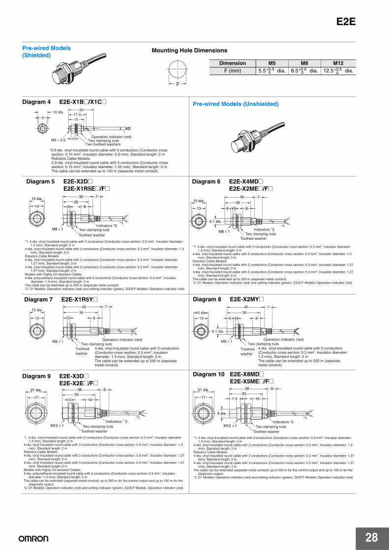
Dimension M5 M8 M12F (mm) 5.5 dia. 8.5 dia. 12.5 dia.+0.5
0+0.5
0+0.5
0
10 dia.17.5
25
158
M5 × 0.5 4
*Operation indicator (red)
Two clamping nutsTwo toothed washers
*2.9-dia. vinyl-insulated round cable with 3 conductors (Conductor cross section: 0.14 mm2, Insulator diameter: 0.9 mm), Standard length: 2 m Robotics Cable Models: 2.9-dia. vinyl-insulated round cable with 3 conductors (Conductor cross section: 0.15 mm2, Insulator diameter: 1.05 mm), Standard length: 2 m The cable can be extended up to 100 m (separate metal conduit).
Diagram 4 E2E-X1B@/X1C@ Pre-wired Models (Unshielded)
30 7
826
3
M8 × 1
13
15 dia.
*1Indicators *2
Two clamping nutsToothed washer
*1. 4-dia. vinyl-insulated round cable with 2 conductors (Conductor cross section: 0.3 mm2, Insulator diameter: 1.3 mm), Standard length: 2 m
4-dia. vinyl-insulated round cable with 3 conductors (Conductor cross section: 0.3 mm2, Insulator diameter: 1.3 mm), Standard length: 2 m
Robotics Cable Models:4-dia. vinyl-insulated round cable with 2 conductors (Conductor cross section: 0.3 mm2, Insulator diameter:
1.27 mm), Standard length: 2 m4-dia. vinyl-insulated round cable with 3 conductors (Conductor cross section: 0.3 mm2, Insulator diameter:
1.27 mm), Standard length: 2 mModels with Highly Oil-resistant Cables:4-dia. polyurethane-insulated round cable with 2 conductors (Conductor cross section: 0.3 mm2, Insulator
diameter: 1.3 mm), Standard length: 2 mThe cable can be extended up to 200 m (separate metal conduit).*2. D1 Models: Operation indicator (red) and setting indicator (green), D2/E/F Models: Operation indicator (red)
Diagram 5 E2E-X2D@E2E-X1R5E@/F@
30 7
8
26
13 6 3
15 dia.
M8 × 1
6.1 dia.*1
Indicators *2Two clamping nuts
Toothed washer
*1. 4-dia. vinyl-insulated round cable with 2 conductors (Conductor cross section: 0.3 mm2, Insulator diameter: 1.3 mm), Standard length: 2 m
4-dia. vinyl-insulated round cable with 3 conductors (Conductor cross section: 0.3 mm2, Insulator diameter: 1.3 mm), Standard length: 2 m
Robotics Cable Models:4-dia. vinyl-insulated round cable with 2 conductors (Conductor cross section: 0.3 mm2, Insulator diameter: 1.27
mm), Standard length: 2 m4-dia. vinyl-insulated round cable with 3 conductors (Conductor cross section: 0.3 mm2, Insulator diameter: 1.27
mm), Standard length: 2 mThe cable can be extended up to 200 m (separate metal conduit).*2. D1 Models: Operation indicator (red) and setting indicator (green), D2/E/F Models: Operation indicator (red)
Diagram 6 E2E-X4MD@E2E-X2ME@/F@
Diagram 7 E2E-X1R5Y@
15 dia.
313
36
8
740
M8 × 1*
Toothed washer
Two clamping nutsOperation indicator (red)
4-dia. vinyl-insulated round cable with 2 conductors (Conductor cross section: 0.3 mm2, Insulator diameter: 1.3 mm), Standard length: 2 m The cable can be extended up to 200 m (separate metal conduit).
Diagram 8 E2E-X2MY@40 7
8
36
13 6 3
15 dia.
M8 × 1
6.1 dia.*
Operation indicator (red)Two clamping nuts
Toothed washer
4-dia. vinyl-insulated round cable with 2 conductors (Conductor cross section: 0.3 mm2, Insulator diameter: 1.3 mm), Standard length: 2 m The cable can be extended up to 200 m (separate metal conduit).
38 9
1033
174
21 dia.
*1
M12 × 1Indicators * 2
Two clamping nutsToothed washer
*1. 4-dia. vinyl-insulated round cable with 2 conductors (Conductor cross section: 0.3 mm2, Insulator diameter: 1.3 mm), Standard length: 2 m
4-dia. vinyl-insulated round cable with 3 conductors (Conductor cross section: 0.3 mm2, Insulator diameter: 1.3 mm), Standard length: 2 m
Robotics Cable Models:4-dia. vinyl-insulated round cable with 2 conductors (Conductor cross section: 0.3 mm2, Insulator diameter: 1.27
mm), Standard length: 2 m4-dia. vinyl-insulated round cable with 3 conductors (Conductor cross section: 0.3 mm2, Insulator diameter: 1.27
mm), Standard length: 2 mModels with Highly Oil-resistant Cables:4-dia. polyurethane-insulated round cable with 2 conductors (Conductor cross section: 0.3 mm2, Insulator
diameter: 1.3 mm), Standard length: 2 mThe cable can be extended (separate metal conduit) up to 200 m for the control output and up to 100 m for the
diagnostic output.*2. D1 Models: Operation indicator (red) and setting indicator (green), D2/E/F Models: Operation indicator (red)
Diagram 9 E2E-X3D@E2E-X2E@/F@
Diagram 10 E2E-X8MD@E2E-X5ME@/F@
38 9
1033
17 7 4
9 dia.
21 dia.
M12 × 1
*1Indicators *2
Two clamping nutsToothed washer
*1. 4-dia. vinyl-insulated round cable with 2 conductors (Conductor cross section: 0.3 mm2, Insulator diameter: 1.3 mm), Standard length: 2 m
4-dia. vinyl-insulated round cable with 3 conductors (Conductor cross section: 0.3 mm2, Insulator diameter: 1.3 mm), Standard length: 2 m
Robotics Cable Models:4-dia. vinyl-insulated round cable with 2 conductors (Conductor cross section: 0.3 mm2, Insulator diameter: 1.27
mm), Standard length: 2 m4-dia. vinyl-insulated round cable with 3 conductors (Conductor cross section: 0.3 mm2, Insulator diameter: 1.27
mm), Standard length: 2 mThe cable can be extended (separate metal conduit) up to 200 m for the control output and up to 100 m for the
diagnostic output.*2. D1 Models: Operation indicator (red) and setting indicator (green), D2/E/F Models: Operation indicator (red)
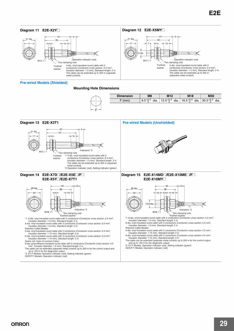
E2E
29
Diagram 11 E2E-X2Y@
43 9
10
38
17 4
21 dia.
M12 × 1
*
Operation indicator (red)Two clamping nuts
Toothed washer
4-dia. vinyl-insulated round cable with 2 conductors (Conductor cross section: 0.3 mm2, Insulator diameter: 1.3 mm), Standard length: 2 m The cable can be extended up to 200 m (separate metal conduit).
Diagram 12 E2E-X5MY@
43 9
10
38
17 7 4
21 dia.
M12 × 1
9 dia.*
Operation indicator (red)Two clamping nuts
Toothed washer
4-dia. vinyl-insulated round cable with 2 conductors (Conductor cross section: 0.3 mm2, Insulator diameter: 1.3 mm), Standard length: 2 m The cable can be extended up to 200 m (separate metal conduit).
Mounting Hole Dimensions
Pre-wired Models (Shielded)
F
Dimension M8 M12 M18 M30F (mm) 8.5 dia. 12.5 dia. 18.5 dia. 30.5 dia.+0.5
0+0.5
0+0.5
0+0.5
0
60 9
10
55
17
21 dia.
4
M12 × 1
*1Indicators *2
Two clamping nutsToothed washer
*1 4-dia. vinyl-insulated round cable with 2 conductors (Conductor cross section: 0.3 mm2, Insulator diameter: 1.3 mm), Standard length: 2 m The cable can be extended up to 200 m (separate metal conduit).
*2 Operation indicator (red), Setting indicator (green)
Diagram 13 E2E-X3T1 Pre-wired Models (Unshielded)
43 12
10
38
424
29 dia.
*1
M18 × 1Indicators *2
Two clamping nutsToothed washer
*1. 6-dia. vinyl-insulated round cable with 2 conductors (Conductor cross section: 0.5 mm2, Insulator diameter: 1.9 mm), Standard length: 2 m
6-dia. vinyl-insulated round cable with 3 conductors (Conductor cross section: 0.5 mm2, Insulator diameter: 1.9 mm), Standard length: 2 m
Robotics Cable Models:6-dia. vinyl-insulated round cable with 2 conductors (Conductor cross section: 0.5 mm2,
Insulator diameter: 1.74 mm), Standard length: 2 m6-dia. vinyl-insulated round cable with 3 conductors (Conductor cross section: 0.5 mm2,
Insulator diameter: 1.74 mm), Standard length: 2 mModels with Highly Oil-resistant Cables:6-dia. polyurethane-insulated round cable with 2 conductors (Conductor cross section: 0.5
mm2, Insulator diameter: 1.9 mm), Standard length: 2 mThe cable can be extended (separate metal conduit) up to 200 m for the control output and
up to 100 m for the diagnostic output.*2. D1/T Models: Operation indicator (red), Setting indicator (green)D2/E/F/Y Models: Operation indicator (red)
Diagram 14 E2E-X7D@/E2E-X5E@/F@E2E-X5Y@/E2E-X7T1
10
43 12
10
38
424
29 dia.
M18 × 1
14.8 dia.*1*1
*1. 6-dia. vinyl-insulated round cable with 2 conductors (Conductor cross section: 0.5 mm2, Insulator diameter: 1.9 mm), Standard length: 2 m
6-dia. vinyl-insulated round cable with 3 conductors (Conductor cross section: 0.5 mm2, Insulator diameter: 1.9 mm), Standard length: 2 m
Robotics Cable Models:6-dia. vinyl-insulated round cable with 2 conductors (Conductor cross section: 0.5 mm2,
Insulator diameter: 1.74 mm), Standard length: 2 m6-dia. vinyl-insulated round cable with 3 conductors (Conductor cross section: 0.5 mm2,
Insulator diameter: 1.74 mm), Standard length: 2 mThe cable can be extended (separate metal conduit) up to 200 m for the control output
and up to 100 m for the diagnostic output.*2. D1/T Models: Operation indicator (red), Setting indicator (green)D2/E/F/Y Models: Operation indicator (red)
Indicators *2
Two clamping nutsToothed washer
Diagram 15 E2E-X14MD@/E2E-X10ME@/F@E2E-X10MY@

30
E2E
48 12
1043
536
42 dia.
M30 × 1.5
*1Indicators *2
Two clamping nutsToothed washer
*1. 6-dia. vinyl-insulated round cable with 2 conductors (Conductor cross section: 0.5 mm2, Insulator diameter: 1.9 mm), Standard length: 2 m
6-dia. vinyl-insulated round cable with 3 conductors (Conductor cross section: 0.5 mm2, Insulator diameter: 1.9 mm), Standard length: 2 m
Robotics Cable Models: 6-dia. vinyl-insulated round cable with 2 conductors (Conductor cross section: 0.5 mm2,
Insulator diameter: 1.74 mm), Standard length: 2 m 6-dia. vinyl-insulated round cable with 3 conductors (Conductor cross section: 0.5 mm2,
Insulator diameter: 1.74 mm), Standard length: 2 m Models with Highly Oil-resistant: 6-dia. polyurethane-insulated round cable with 2 conductors (Conductor cross section:
0.5 mm2, Insulator diameter: 1.9 mm), Standard length: 2 m The cable can be extended (separate metal conduit) up to 200 m for the control output
and up to 100 m for the diagnostic output.*2. D1/T Models: Operation indicator (red), Setting indicator (green) D2/E/F/Y Models: Operation indicator (red)
Diagram 16 E2E-X10D@/E2E-X10E@/F@E2E-X10Y@/E2E-X10T1
48 12
1013
43
536
42 dia.
M30 × 1.5
26.8 dia.*1
Indicators *2
Two clamping nutsToothed washer
*1. 6-dia. vinyl-insulated round cable with 2 conductors (Conductor cross section: 0.5 mm2, Insulator diameter: 1.9 mm), Standard length: 2 m
6-dia. vinyl-insulated round cable with 3 conductors (Conductor cross section: 0.5 mm2, Insulator diameter: 1.9 mm), Standard length: 2 m
Robotics Cable Models: 6-dia. vinyl-insulated round cable with 2 conductors (Conductor cross section: 0.5 mm2,
Insulator diameter: 1.74 mm), Standard length: 2 m 6-dia. vinyl-insulated round cable with 3 conductors (Conductor cross section: 0.5 mm2,
Insulator diameter: 1.74 mm), Standard length: 2 m The cable can be extended (separate metal conduit) up to 200 m for the control output
and up to 100 m for the diagnostic output.*2. D1/T Models: Operation indicator (red), Setting indicator (green) D2/E/F/Y Models: Operation indicator (red)
Diagram 17 E2E-X20MD@/E2E-X18ME@/F@E2E-X18MY@
M8 Connector Models (Shielded)
M8 Connector Models (Unshielded)
M8 × 1
3931
8
26
13 3
15 dia.
M8 × 1 Indicators*
Toothed washerTwo clamping nuts
* D Models: Operation indicator (red), Setting indicator (green)
D2/E/F Models: Operation indicator (red)
Diagram 28 E2E-X2D@-M3G/E2E-X1R5E@-M3/X1RF@-M3
M8 × 1
39
31
8
26
13 6 3
15 dia.
M8 × 1
6.1 dia.
Indicators*
Toothed washerTwo clamping nuts
* D Models: Operation indicator (red), Setting indicator (green)
D2/E/F Models: Operation indicator (red)
Diagram 29 E2E-X4MD@-M3G/E2E-X2ME@-M3/X2MF@-M3
M12 Connector Models (Shielded)
M12 Connector Models (Unshielded)
M12 × 1
4330
8
26
13 3
15 dia.
M8 × 1 Indicators*
Toothed washerTwo clamping nuts
* D1 Models: Operation indicator (red), Setting indicator (green)
D2/E/F Models: Operation indicator (red)
Diagram 18 E2E-X2D@-M1(G)E2E-X1R5E@-M1/E2E-X1R5F@-M1
M12 × 1
43
30
8
26
13 6 3
6.1 dia.
15 dia.
M8 × 1 Indicators*Two clamping nuts
Toothed washer
* D1 Models: Operation indicator (red), Setting indicator (green)
D2/E/F Models: Operation indicator (red)
Diagram 19 E2E-X4MD@-M1(G)E2E-X2ME@-M1/E2E-X2MF@-M1
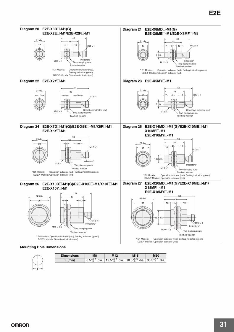
E2E
31
M12 × 1
48
10
33
17 4
21 dia.
M12 × 1 Indicators *
Toothed washerTwo clamping nuts
* D1 Models: Operation indicator (red), Setting indicator (green)
D2/E/F Models: Operation indicator (red)
Diagram 20 E2E-X3D@-M1(G)E2E-X2E@-M1/E2E-X2F@-M1
M12 × 1
48
10
33
17 7 4
21 dia.
M12 × 1
9 dia.
Indicators*
Toothed washerTwo clamping nuts
* D1 Models: Operation indicator (red), Setting indicator (green) D2/E/F Models: Operation indicator (red)
Diagram 21 E2E-X8MD@-M1(G)E2E-X5ME@-M1/E2E-X5MF@-M1
M12 × 1
53
10
38
17 4
21 dia.
M12 × 1 Operation indicator (red)
Toothed washer
Two clamping nuts
Diagram 22 E2E-X2Y@-M1
M12 × 1
53
10
38
17 7 4
21 dia.
M12 × 1
9 dia.
Operation indicator (red)
Toothed washerTwo clamping nuts
Diagram 23 E2E-X5MY@-M1
M12 × 1
53
10
38
24 4
29 dia.
M18 × 1Indicators*
Two clamping nuts
Toothed washer
* D1 Models: Operation indicator (red), Setting indicator (green) D2/E/Y Models: Operation indicator (red)
Diagram 24 E2E-X7D@-M1(G)/E2E-X5E@-M1/X5F@-M1E2E-X5Y@-M1
M12 × 1
53
10
38
24 104
29 dia.
M18 × 1
14.8 dia.
Indicators*
Toothed washerTwo clamping nuts
* D1 Models: Operation indicator (red), Setting indicator (green) D2/E/Y Models: Operation indicator (red)
Diagram 25 E2E-X14MD@-M1(G)/E2E-X10ME@-M1X10MF@-M1E2E-X10MY@-M1
58
10
43
36 5
42 dia.
M30 × 1.5
M12 × 1Indicators*
Two clamping nuts
Toothed washer
* D1 Models: Operation indicator (red), Setting indicator (green) D2/E/Y Models: Operation indicator (red)
Diagram 26 E2E-X10D@-M1(G)/E2E-X10E@-M1/X10F@-M1E2E-X10Y@-M1
58
10
43
36 13 5
42 dia.
M30 × 1.5
26.8 dia.
M12 × 1Indicators*
Two clamping nuts
Toothed washer
* D1 Models: Operation indicator (red), Setting indicator (green) D2/E/Y Models: Operation indicator (red)
Diagram 27 E2E-X20MD@-M1(G)/E2E-X18ME@-M1/X18MF@-M1E2E-X18MY@-M1
Mounting Hole Dimensions
F
Dimensions M8 M12 M18 M30F (mm) 8.5 dia. 12.5 dia. 18.5 dia. 30.5 dia.+0.5
0+0.5
0+0.5
0+0.5
0
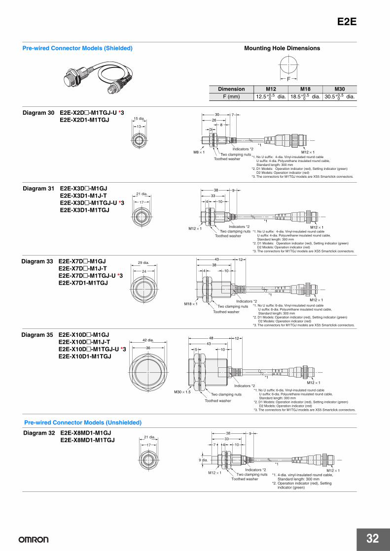
32
E2E
Pre-wired Connector Models (Unshielded)
Dimension M12 M18 M30F (mm) 12.5 dia. 18.5 dia. 30.5 dia.+0.5
0+0.5
0+0.5
0
Pre-wired Connector Models (Shielded) Mounting Hole Dimensions
F
730
826
3
M8 × 1
*1
M12 × 1Indicators *2
Toothed washerTwo clamping nuts
*1. No U suffix: 4-dia. Vinyl-insulated round cable U suffix: 4-dia. Polyurethane insulated round cable, Standard length: 300 mm*2. D1 Models: Operation indicator (red), Setting indicator (green) D2 Models: Operation indicator (red)*3. The connectors for M1TGJ models are XS5 Smartclick connectors.
15 dia.
13
Diagram 30 E2E-X2D@-M1TGJ-U *3E2E-X2D1-M1TGJ
Diagram 31 E2E-X3D@-M1GJE2E-X3D1-M1J-TE2E-X3D@-M1TGJ-U *3E2E-X3D1-M1TGJ
938
10
33
4
M12 × 1
*1
M12 × 1
21 dia.
17
Indicators *2
Toothed washerTwo clamping nuts *1. No U suffix: 4-dia. Vinyl-insulated round cable
U suffix: 4-dia. Polyurethane insulated round cable, Standard length: 300 mm*2. D1 Models: Operation indicator (red), Setting indicator (green) D2 Models: Operation indicator (red)*3. The connectors for M1TGJ models are XS5 Smartclick connectors.
Diagram 33 E2E-X7D@-M1GJE2E-X7D@-M1J-TE2E-X7D@-M1TGJ-U *3E2E-X7D1-M1TGJ
1243
*1
10
38
4
M18 × 1M12 × 1
29 dia.
24
Indicators *2
Toothed washer
Two clamping nuts *1. No U suffix: 6-dia. Vinyl-insulated round cable U suffix: 6-dia. Polyurethane insulated round cable, Standard length: 300 mm*2. D1 Models: Operation indicator (red), Setting indicator (green) D2 Models: Operation indicator (red)*3. The connectors for M1TGJ models are XS5 Smartclick connectors.
Diagram 35 E2E-X10D@-M1GJE2E-X10D@-M1J-TE2E-X10D@-M1TGJ-U *3E2E-X10D1-M1TGJ
1248
10
4336 5
42 dia.
M30 × 1.5
*1
M12 × 1Indicators *2
Toothed washer
Two clamping nuts*1. No U suffix: 6-dia. Vinyl-insulated round cable U suffix: 6-dia. Polyurethane insulated round cable, Standard length: 300 mm*2. D1 Models: Operation indicator (red), Setting indicator (green) D2 Models: Operation indicator (red)*3. The connectors for M1TGJ models are XS5 Smartclick connectors.
Diagram 32 E2E-X8MD1-M1GJE2E-X8MD1-M1TGJ
938
10
33
17 7 4
9 dia.
21 dia.
M12 × 1
*1
M12 × 1Indicators *2
Toothed washerTwo clamping nuts *1. 4-dia. vinyl-insulated round cable,
Standard length: 300 mm*2. Operation indicator (red), Setting
indicator (green)
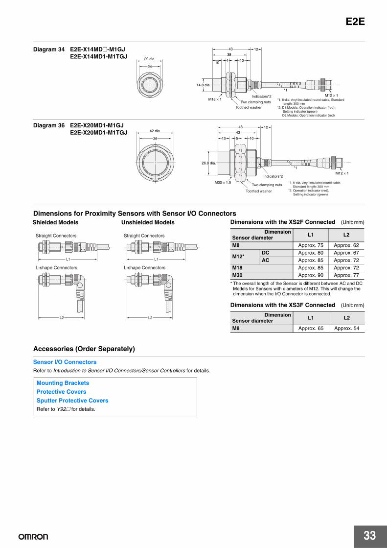
E2E
33
Dimensions for Proximity Sensors with Sensor I/O Connectors
Accessories (Order Separately)
Sensor I/O ConnectorsRefer to Introduction to Sensor I/O Connectors/Sensor Controllers for details.
Diagram 34 E2E-X14MD@-M1GJE2E-X14MD1-M1TGJ
1243
10
38
2410
429 dia.
M18 × 1
14.8 dia.*1
M12 × 1Indicators*2
Toothed washerTwo clamping nuts
*1. 6-dia. vinyl-insulated round cable, Standard length: 300 mm
*2. D1 Models: Operation indicator (red), Setting indicator (green)
D2 Models: Operation indicator (red)
Diagram 36 E2E-X20MD1-M1GJE2E-X20MD1-M1TGJ
1248
*1
10
43
36 13 5
26.8 dia.
42 dia.
M30 × 1.5
M12 × 1Indicators*2
Toothed washer
Two clamping nuts*1. 6-dia. vinyl-insulated round cable,
Standard length: 300 mm*2. Operation indicator (red), Setting indicator (green)
L1
L2
L1
L2
Straight Connectors
L-shape Connectors
Straight Connectors
L-shape Connectors
Shielded Models Unshielded Models Dimensions with the XS2F Connected (Unit: mm)
* The overall length of the Sensor is different between AC and DC Models for Sensors with diameters of M12. This will change the dimension when the I/O Connector is connected.
Dimensions with the XS3F Connected (Unit: mm)
DimensionSensor diameter L1 L2
M8 Approx. 75 Approx. 62
M12*DC Approx. 80 Approx. 67AC Approx. 85 Approx. 72
M18 Approx. 85 Approx. 72M30 Approx. 90 Approx. 77
DimensionSensor diameter L1 L2
M8 Approx. 65 Approx. 54
Mounting Brackets
Protective Covers
Sputter Protective CoversRefer to Y92@ for details.
Terms and Conditions of Sale1. Offer; Acceptance. These terms and conditions (these "Terms") are deemed
part of all quotes, agreements, purchase orders, acknowledgments, price lists,catalogs, manuals, brochures and other documents, whether electronic or inwriting, relating to the sale of products or services (collectively, the "Products")by Omron Electronics LLC and its subsidiary companies (“Omron”). Omronobjects to any terms or conditions proposed in Buyer’s purchase order or otherdocuments which are inconsistent with, or in addition to, these Terms.
2. Prices; Payment Terms. All prices stated are current, subject to change with-out notice by Omron. Omron reserves the right to increase or decrease priceson any unshipped portions of outstanding orders. Payments for Products aredue net 30 days unless otherwise stated in the invoice.
3. Discounts. Cash discounts, if any, will apply only on the net amount of invoicessent to Buyer after deducting transportation charges, taxes and duties, and willbe allowed only if (i) the invoice is paid according to Omron’s payment termsand (ii) Buyer has no past due amounts.
4. Interest. Omron, at its option, may charge Buyer 1-1/2% interest per month orthe maximum legal rate, whichever is less, on any balance not paid within thestated terms.
5. Orders. Omron will accept no order less than $200 net billing. 6. Governmental Approvals. Buyer shall be responsible for, and shall bear all
costs involved in, obtaining any government approvals required for the impor-tation or sale of the Products.
7. Taxes. All taxes, duties and other governmental charges (other than generalreal property and income taxes), including any interest or penalties thereon,imposed directly or indirectly on Omron or required to be collected directly orindirectly by Omron for the manufacture, production, sale, delivery, importa-tion, consumption or use of the Products sold hereunder (including customsduties and sales, excise, use, turnover and license taxes) shall be charged toand remitted by Buyer to Omron.
8. Financial. If the financial position of Buyer at any time becomes unsatisfactoryto Omron, Omron reserves the right to stop shipments or require satisfactorysecurity or payment in advance. If Buyer fails to make payment or otherwisecomply with these Terms or any related agreement, Omron may (without liabil-ity and in addition to other remedies) cancel any unshipped portion of Prod-ucts sold hereunder and stop any Products in transit until Buyer pays allamounts, including amounts payable hereunder, whether or not then due,which are owing to it by Buyer. Buyer shall in any event remain liable for allunpaid accounts.
9. Cancellation; Etc. Orders are not subject to rescheduling or cancellationunless Buyer indemnifies Omron against all related costs or expenses.
10. Force Majeure. Omron shall not be liable for any delay or failure in deliveryresulting from causes beyond its control, including earthquakes, fires, floods,strikes or other labor disputes, shortage of labor or materials, accidents tomachinery, acts of sabotage, riots, delay in or lack of transportation or therequirements of any government authority.
11. Shipping; Delivery. Unless otherwise expressly agreed in writing by Omron:a. Shipments shall be by a carrier selected by Omron; Omron will not drop ship
except in “break down” situations.b. Such carrier shall act as the agent of Buyer and delivery to such carrier shall
constitute delivery to Buyer;c. All sales and shipments of Products shall be FOB shipping point (unless oth-
erwise stated in writing by Omron), at which point title and risk of loss shallpass from Omron to Buyer; provided that Omron shall retain a security inter-est in the Products until the full purchase price is paid;
d. Delivery and shipping dates are estimates only; ande. Omron will package Products as it deems proper for protection against nor-
mal handling and extra charges apply to special conditions.12. Claims. Any claim by Buyer against Omron for shortage or damage to the
Products occurring before delivery to the carrier must be presented in writingto Omron within 30 days of receipt of shipment and include the original trans-portation bill signed by the carrier noting that the carrier received the Productsfrom Omron in the condition claimed.
13. Warranties. (a) Exclusive Warranty. Omron’s exclusive warranty is that theProducts will be free from defects in materials and workmanship for a period oftwelve months from the date of sale by Omron (or such other period expressedin writing by Omron). Omron disclaims all other warranties, express or implied.(b) Limitations. OMRON MAKES NO WARRANTY OR REPRESENTATION,EXPRESS OR IMPLIED, ABOUT NON-INFRINGEMENT, MERCHANTABIL-
ITY OR FITNESS FOR A PARTICULAR PURPOSE OF THE PRODUCTS.BUYER ACKNOWLEDGES THAT IT ALONE HAS DETERMINED THAT THEPRODUCTS WILL SUITABLY MEET THE REQUIREMENTS OF THEIRINTENDED USE. Omron further disclaims all warranties and responsibility ofany type for claims or expenses based on infringement by the Products or oth-erwise of any intellectual property right. (c) Buyer Remedy. Omron’s sole obli-gation hereunder shall be, at Omron’s election, to (i) replace (in the formoriginally shipped with Buyer responsible for labor charges for removal orreplacement thereof) the non-complying Product, (ii) repair the non-complyingProduct, or (iii) repay or credit Buyer an amount equal to the purchase price ofthe non-complying Product; provided that in no event shall Omron be responsi-ble for warranty, repair, indemnity or any other claims or expenses regardingthe Products unless Omron’s analysis confirms that the Products were prop-erly handled, stored, installed and maintained and not subject to contamina-tion, abuse, misuse or inappropriate modification. Return of any Products byBuyer must be approved in writing by Omron before shipment. Omron Compa-nies shall not be liable for the suitability or unsuitability or the results from theuse of Products in combination with any electrical or electronic components,circuits, system assemblies or any other materials or substances or environ-ments. Any advice, recommendations or information given orally or in writing,are not to be construed as an amendment or addition to the above warranty.See http://www.omron247.com or contact your Omron representative for pub-lished information.
14. Limitation on Liability; Etc. OMRON COMPANIES SHALL NOT BE LIABLEFOR SPECIAL, INDIRECT, INCIDENTAL, OR CONSEQUENTIAL DAMAGES,LOSS OF PROFITS OR PRODUCTION OR COMMERCIAL LOSS IN ANYWAY CONNECTED WITH THE PRODUCTS, WHETHER SUCH CLAIM ISBASED IN CONTRACT, WARRANTY, NEGLIGENCE OR STRICT LIABILITY.Further, in no event shall liability of Omron Companies exceed the individualprice of the Product on which liability is asserted.
15. Indemnities. Buyer shall indemnify and hold harmless Omron Companies andtheir employees from and against all liabilities, losses, claims, costs andexpenses (including attorney's fees and expenses) related to any claim, inves-tigation, litigation or proceeding (whether or not Omron is a party) which arisesor is alleged to arise from Buyer's acts or omissions under these Terms or inany way with respect to the Products. Without limiting the foregoing, Buyer (atits own expense) shall indemnify and hold harmless Omron and defend or set-tle any action brought against such Companies to the extent based on a claimthat any Product made to Buyer specifications infringed intellectual propertyrights of another party.
16. Property; Confidentiality. Any intellectual property in the Products is the exclu-sive property of Omron Companies and Buyer shall not attempt to duplicate itin any way without the written permission of Omron. Notwithstanding anycharges to Buyer for engineering or tooling, all engineering and tooling shallremain the exclusive property of Omron. All information and materials suppliedby Omron to Buyer relating to the Products are confidential and proprietary,and Buyer shall limit distribution thereof to its trusted employees and strictlyprevent disclosure to any third party.
17. Export Controls. Buyer shall comply with all applicable laws, regulations andlicenses regarding (i) export of products or information; (iii) sale of products to“forbidden” or other proscribed persons; and (ii) disclosure to non-citizens ofregulated technology or information.
18. Miscellaneous. (a) Waiver. No failure or delay by Omron in exercising any rightand no course of dealing between Buyer and Omron shall operate as a waiverof rights by Omron. (b) Assignment. Buyer may not assign its rights hereunderwithout Omron's written consent. (c) Law. These Terms are governed by thelaw of the jurisdiction of the home office of the Omron company from whichBuyer is purchasing the Products (without regard to conflict of law princi-ples). (d) Amendment. These Terms constitute the entire agreement betweenBuyer and Omron relating to the Products, and no provision may be changedor waived unless in writing signed by the parties. (e) Severability. If any provi-sion hereof is rendered ineffective or invalid, such provision shall not invalidateany other provision. (f) Setoff. Buyer shall have no right to set off any amountsagainst the amount owing in respect of this invoice. (g) Definitions. As usedherein, “including” means “including without limitation”; and “Omron Compa-nies” (or similar words) mean Omron Corporation and any direct or indirectsubsidiary or affiliate thereof.
Certain Precautions on Specifications and Use1. Suitability of Use. Omron Companies shall not be responsible for conformity
with any standards, codes or regulations which apply to the combination of theProduct in the Buyer’s application or use of the Product. At Buyer’s request,Omron will provide applicable third party certification documents identifyingratings and limitations of use which apply to the Product. This information byitself is not sufficient for a complete determination of the suitability of the Prod-uct in combination with the end product, machine, system, or other applicationor use. Buyer shall be solely responsible for determining appropriateness ofthe particular Product with respect to Buyer’s application, product or system.Buyer shall take application responsibility in all cases but the following is anon-exhaustive list of applications for which particular attention must be given:(i) Outdoor use, uses involving potential chemical contamination or electricalinterference, or conditions or uses not described in this document.(ii) Use in consumer products or any use in significant quantities. (iii) Energy control systems, combustion systems, railroad systems, aviationsystems, medical equipment, amusement machines, vehicles, safety equip-ment, and installations subject to separate industry or government regulations. (iv) Systems, machines and equipment that could present a risk to life or prop-erty. Please know and observe all prohibitions of use applicable to this Prod-uct. NEVER USE THE PRODUCT FOR AN APPLICATION INVOLVING SERIOUSRISK TO LIFE OR PROPERTY OR IN LARGE QUANTITIES WITHOUTENSURING THAT THE SYSTEM AS A WHOLE HAS BEEN DESIGNED TO
ADDRESS THE RISKS, AND THAT THE OMRON’S PRODUCT IS PROP-ERLY RATED AND INSTALLED FOR THE INTENDED USE WITHIN THEOVERALL EQUIPMENT OR SYSTEM.
2. Programmable Products. Omron Companies shall not be responsible for theuser’s programming of a programmable Product, or any consequence thereof.
3. Performance Data. Data presented in Omron Company websites, catalogsand other materials is provided as a guide for the user in determining suitabil-ity and does not constitute a warranty. It may represent the result of Omron’stest conditions, and the user must correlate it to actual application require-ments. Actual performance is subject to the Omron’s Warranty and Limitationsof Liability.
4. Change in Specifications. Product specifications and accessories may bechanged at any time based on improvements and other reasons. It is our prac-tice to change part numbers when published ratings or features are changed,or when significant construction changes are made. However, some specifica-tions of the Product may be changed without any notice. When in doubt, spe-cial part numbers may be assigned to fix or establish key specifications foryour application. Please consult with your Omron’s representative at any timeto confirm actual specifications of purchased Product.
5. Errors and Omissions. Information presented by Omron Companies has beenchecked and is believed to be accurate; however, no responsibility is assumedfor clerical, typographical or proofreading errors or omissions.
OMRON CANADA, INC. • HEAD OFFICEToronto, ON, Canada • 416.286.6465 • 866.986.6766 • www.omron247.com
OMRON ELECTRONICS DE MEXICO • HEAD OFFICEMéxico DF • 52.55.59.01.43.00 • 01-800-226-6766 • [email protected]
OMRON ELECTRONICS DE MEXICO • SALES OFFICEApodaca, N.L. • 52.81.11.56.99.20 • 01-800-226-6766 • [email protected]
OMRON ELETRÔNICA DO BRASIL LTDA • HEAD OFFICESão Paulo, SP, Brasil • 55.11.2101.6300 • www.omron.com.br
OMRON ARGENTINA • SALES OFFICECono Sur • 54.11.4783.5300
OMRON CHILE • SALES OFFICESantiago • 56.9.9917.3920
OTHER OMRON LATIN AMERICA SALES54.11.4783.5300
Authorized Distributor:
E62I-E-02 06/14 Note: Specifications are subject to change. © 2014 Omron Electronics LLC Printed in U.S.A.
Printed on recycled paper.
Automation Control Systems• Machine Automation Controllers (MAC) • Programmable Controllers (PLC) • Operator interfaces (HMI) • Distributed I/O • Software
Drives & Motion Controls • Servo & AC Drives • Motion Controllers & Encoders
Temperature & Process Controllers • Single and Multi-loop Controllers
Sensors & Vision• Proximity Sensors • Photoelectric Sensors • Fiber-Optic Sensors• Amplified Photomicrosensors • Measurement Sensors• Ultrasonic Sensors • Vision Sensors
Industrial Components • RFID/Code Readers • Relays • Pushbuttons & Indicators • Limit and Basic Switches • Timers • Counters • Metering Devices • Power Supplies
Safety • Laser Scanners • Safety Mats • Edges and Bumpers • Programmable Safety Controllers • Light Curtains • Safety Relays • Safety Interlock Switches
OMRON AUTOMATION AND SAFETY • THE AMERICAS HEADQUARTERS • Chicago, IL USA • 847.843.7900 • 800.556.6766 • www.omron247.com
OMRON EUROPE B.V. • Wegalaan 67-69, NL-2132 JD, Hoofddorp, The Netherlands. • +31 (0) 23 568 13 00 • www.industrial.omron.eu