Embed Size (px)
Citation preview

PUBLIC CONSULTATION DRAFT Issued: February 2009
Project No: 2870
STANDARDS AUSTRALIA
Committee ME-064—Access for People with Disabilities
Australian Standard
Design for access and mobility Part 1: General requirements for access—New building work
2870-PDR - 02/02/2009 11:09:45

DRAFT ONLY 2 DRAFT ONLY
PREFACE This Standard was prepared by the Standards Australia Committee ME-064, Access for People with Disabilities.
This edition supersedes AS 1428.1—2001 and is part of a series which is comprised of the following:
AS 1428 Design for access and mobility 1428.1 Part 1: General requirements for access—New building work 1428.2 Part 2: Interior fitout of buildings 1428.3 Part 3: Requirements for children and adolescents with physical disabilities 1428.4 Part 4: Tactile indicators, signage, and features to assist people with vision
impairment 1428.5 Part 5: Design for communication—Hearing augmentation—Assistive
listening systems, visual announcements, early warning systems to assist people with a hearing impairment
1428.6 Part 6: Purpose-built buildings 1428.7 Part 7: Outdoor access 1428.8 Part 8: Adaptable housing 1428.9 Part 9: Aged care facilities
The objective of this Standard is to provide building designers and users (architects, property owners, regulators, and the like) with the minimum design requirements for new building work to enable access for people with disabilities.
Because of the variety of situations which may need to be addressed when designing buildings and facilities, it is seen as necessary for the Standard to provide a range of data so that the requirements for access can be met and allow for flexibility in design where limitations are imposed by other building conditions. The intention is to make the Standard a practical reference document for designers, particularly with regard to problem areas such as doorways and sanitary facilities. To assist in the designing of combined sanitary facilities, a set of transparent overlays for each sanitary facility, i.e., WC, washbasin and shower recess, together with the required circulation space has been provided with the Standard.
Part 1 of AS 1428 series (this Standard) deals with those aspects of access to and within a building which are regulated by the BCA.
The terms ‘normative’ and ‘informative’ have been used in this Standard to define the application of the appendix to which they apply. A ‘normative’ appendix is an integral part of a Standard, whereas an ‘informative’ appendix is only for information and guidance.
The use of Notes in this Standard are of an advisory nature only to give explanation or guidance to the user on recommended design considerations or technical procedures, or to provide an informative cross-reference to other documents or publications. Notes to clauses in this Standard do not form a mandatory part for compliance with this Standard.
Footnotes to tables and figures are deemed to be requirements of this Standard.
2870-PDR - 02/02/2009 11:09:45

DRAFT ONLY 3 DRAFT ONLY
CONTENTS
Page
FOREWORD.............................................................................................................................. 4 1 SCOPE........................................................................................................................ 5 2 APPLICATION........................................................................................................... 5 3 REFERENCED DOCUMENTS .................................................................................. 6 4 DEFINITIONS............................................................................................................ 6 5 DIMENSIONS ............................................................................................................ 8 6 LUMINANCE CONTRAST ....................................................................................... 8 7 CONTINUOUS ACCESSIBLE PATHS OF TRAVEL ............................................... 9 9 SIGNAGE ................................................................................................................. 18 10 TACTILE GROUND SURFACE INDICATORS ..................................................... 22 11 WALKWAYS, RAMPS AND LANDINGS.............................................................. 22 12 STAIRWAYS ........................................................................................................... 43 13 HANDRAILS............................................................................................................ 48 14 DOORWAYS, DOORS AND CIRCULATION SPACE AT DOORWAYS ............. 50 15 SWITCHES AND GENERAL PURPOSE OUTLETS (POWER POINTS) .............. 61 16 SANITARY FACILITIES......................................................................................... 61 17 GRABRAILS ............................................................................................................ 88 18 ASSEMBLY BUILDINGS ....................................................................................... 88
APPENDICES A EXAMPLES OF KERBS........................................................................................... 92 B THE MEASUREMENT OF LUMINANCE CONTRAST BETWEEN
BUILDING ELEMENTS........................................................................................... 94
2870-PDR - 02/02/2009 11:09:45

DRAFT ONLY 4 DRAFT ONLY
FOREWORD This Standard describes a basic minimum technical detail for accessible buildings.
The BCA provides information on which classes of buildings are to be made accessible and prescribes the specific areas within those buildings where access must be provided. The BCA refers to this Standard and other Standards as a means of compliance with the deemed-to-satisfy access provisions of the BCA.
2870-PDR - 02/02/2009 11:09:45

DRAFT ONLY 5 DRAFT ONLY
STANDARDS AUSTRALIA
Australian Standard Design for access and mobility
Part 1: General requirements for access—New building work
1 SCOPE
This Standard specifies the design requirements applicable to new building work, as required by the Building Code of Australia (BCA), to provide access for people with disabilities. Particular attention is given to—
(a) continuous accessible paths of travel and circulation spaces for people who use wheelchairs;
(b) access and facilities for people with ambulatory disabilities; and
(c) access for people with sensory disabilities.
The BCA sets out requirements for other features of the accessible built environment not covered in this Standard, such as lifts, hearing augmentation, tactile ground surface indicators, signage, glazing, lighting, car parking and toilet numbers, and distribution.
This Standard does not include requirements for—
(i) wheelchairs that have dimensions exceeding those shown in Figure 1.
(ii) motorized scooters.
2 APPLICATION
This Standard is referenced by the BCA for the provision of access for people with disabilities. As a BCA referenced document it is applied to buildings as and when specified in the BCA. Compliance with this Standard may also be required by other regulatory authorities This Standard describes the technical detail required to achieve the level of access for a deemed-to-satisfy solution.
The requirements specified in this Standard are intended to permit general use of buildings and facilities by people with disabilities acting independently, or where a person’s usual method of operation is with an assistant, in the company of that assistant.
The Standard is based on data resulting from empirical testing of persons aged between 18 and 60 years and may be appropriate when applied to persons outside this age range.
The dimensions stated in this Standard, relevant to the use of wheelchairs, relate to the 80th/90th percentile wheelchair size and user (see Figure 1), except at the following locations where the 90th percentile dimensions are required:
(a) On an accessway, at the location of a turn greater than 60 degrees.
(b) New accessible sanitary facilities.
(c) At doorways, including door width and circulation space.
The majority of the dimensions relevant to the 90th percentile in this Standard were based on the findings of research undertaken by J Bails, 1983.
This Standard will be referenced in the BCA, thereby superseding the previous edition, AS 1428.1—2001, which will be withdrawn 12 months from the date of the publication of this edition.
2870-PDR - 02/02/2009 11:09:45
DRAFT ONLY 6 DRAFT ONLY
DIMENSIONS IN MILLIMETRES
FIGURE 1 FOOTPRINT FOR AN OCCUPIED WHEELCHAIR
3 REFERENCED DOCUMENTS
The following documents are referred to in this Standard:
AS 2700 Colour standards for general purposes
AS/NZS 1170 Structural design actions 1170.0 Part 0: General principles 1170.1 Part 1: Permanent, imposed and other actions
1428 Design for access and mobility 1428.4.1 Part 4.1: Tactile ground surface indicators
ABCB BCA Building Code of Australia
4 DEFINITIONS
For the purpose of this Standard, the definitions below apply.
4.1 Accessible
Having features to enable use by people with a disability.
4.2 Angle of approach
The angle between the centre-line of one continuous accessible path of travel and the centre-line of an intersecting continuous accessible path of travel.
4.3 Braille
A system of touch reading for the blind, which employs raised dots, evenly arranged in quadrangular letter spaces or cells.
2870-PDR - 02/02/2009 11:09:45

DRAFT ONLY 7 DRAFT ONLY
4.4 Circulation space
A clear unobstructed flat area as specified in this Standard with a minimum clear height of 2000 mm above the pedestrian surface.
4.5 Continuous accessible path of travel
An uninterrupted path of travel to, into or within a building providing access to all required accessible facilities.
4.6 Encroachment
The intrusion of a building component, fixture or fitment into a continuous accessible path of travel or circulation space.
4.7 Hazard
Any area or fixed object within the environment that may place people at risk.
4.8 Kerb
A side barrier to a trafficable or accessible pedestrian surface.
4.9 Landing
A flat or crowned surface with a gradient not steeper than 1 in 40 from the horizontal, e.g., a rest area on a ramp, stairway or walkway.
4.10 Luminance contrast
The light reflected from one surface or component, compared to the light reflected from another surface or component.
4.11 Luminance factor
The ratio of luminance of a surface to that of a perfect reflector, identically illuminated.
4.12 People with ambulant disabilities
People who have a mobility disability but are able to walk.
4.13 Rail
4.13.1 Grabrail
A rail used to give a steadying or stabilizing assistance to a person engaged in a particular function.
4.13.2 Handrail
A rail used in circulation areas such as corridors, passageways, ramps and stairways to assist in continuous movement.
4.14 Ramp
An inclined surface on a continuous accessible path of travel between two horizontal surfaces (e.g., landings) with a gradient steeper than 1 in 20 but not steeper than 1 in 14.
4.14.1 Kerb ramp
An inclined surface on a continuous accessible path of travel with a maximum rise of 190 mm, a length not greater than 1520 mm and a gradient not steeper than 1 in 8, located within or attached to a kerb.
4.14.2 Step ramp
An inclined surface on a continuous accessible path of travel with a maximum rise of 190 mm and length not greater than 1900 mm and a gradient between not steeper than 1:10.
2870-PDR - 02/02/2009 11:09:45

DRAFT ONLY 8 DRAFT ONLY
4.14.3 Threshold ramp
An inclined surface on a continuous accessible path of travel with a maximum rise of 35 mm and length not greater than 280 mm and a gradient not steeper than 1 in 8.
4.15 Sensory impairment
Any significant loss of hearing or vision.
4.16 Slip resistant
Frictional force opposing movement of an object across a surface, usually with reference to the sole or heel of a shoe on a pedestrian surface.
4.17 Sole-occupancy unit
Means a room or other part of a building for occupation by one or joint owner, lessee, tenant, or other occupier to the exclusion of any other owner, lessee, tenant or other occupier and includes—
(a) a dwelling; or
(b) a room or suite of rooms in a Class 3 building as defined in the BCA which includes sleeping facilities; or
(c) a room or suite of associated rooms in a Class 5, 6, 7, 8 or 9 building as defined in the BCA; or
(d) a room or suite of associated rooms in a Class 9c aged care building as defined in the BCA, which includes sleeping facilities and any area for the exclusive use of a resident.
4.18 Tactile ground surface indicator (TGSI)
Truncated cones and or bars installed on the ground or floor surface designed to provide pedestrians who are blind or vision-impaired with warning or directional orientation information.
4.19 Tactile signs
Signage incorporating raised text, and/or symbols and Braille to enable touch reading by people who are blind or have a vision impairment.
4.20 Walkway
Any surface on a continuous accessible path of travel with a gradient not steeper than 1 in 20.
5 DIMENSIONS
The dimensions given throughout this Standard are in millimetres unless shown otherwise. All dimensions are net and shall not be reduced by projecting skirtings, kerbs, handrails or other fixtures.
Dimensions refer to finished surfaces, e.g., face of wall tiles and floor finishes.
Unless otherwise indicated, limiting dimensions for inclined surface on a continuous accessible path of travel shall be taken as horizontal and vertical only.
6 LUMINANCE CONTRAST
Designers and specifiers shall select various building elements that achieve a high luminance contrast.
Where it is required to achieve a minimum luminance contrast of 30%.
Appendix B sets out test methods for measuring luminance contrast.
2870-PDR - 02/02/2009 11:09:45

DRAFT ONLY 9 DRAFT ONLY
Reflectance values of some products may be obtained from manufacturers and suppliers.
7 CONTINUOUS ACCESSIBLE PATHS OF TRAVEL
7.1 General
A continuous accessible path of travel shall not include a step, stairway, turnstile, revolving door, escalator, moving walk or other impediment.
7.2 Heights of a continuous accessible path of travel
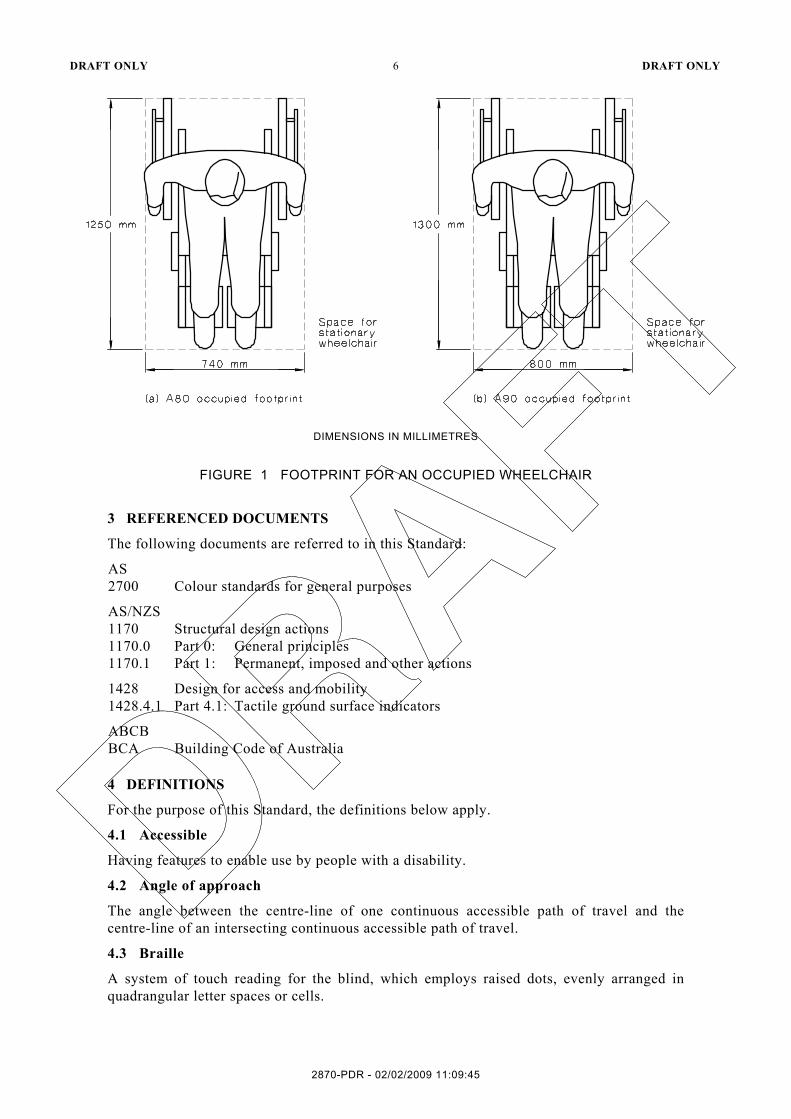
The minimum unobstructed height of a continuous accessible path of travel shall be 2000 mm or 1980 mm at doorways (see Figure 2).
7.3 Width of a continuous accessible path of travel
Unless otherwise specified (such as at doors, curved ramps and similar), the minimum unobstructed width (see Figure 2) of a continuous accessible path of travel shall be 1000 mm (see Clause 14.3) and the following shall not intrude into the minimum unobstructed width of a continuous accessible path of travel:
(a) Fixtures and fittings such as lights, awnings, opening windows, telephones, skirtings and similar objects.
(b) Essential fixtures and fittings such as fire hose reels, fire extinguishers and switchboards.
(c) Door handles less than 900 mm above the finished floor level.
2870-PDR - 02/02/2009 11:09:45
DRAFT ONLY 10 DRAFT ONLY
DIMENSIONS IN MILLIMETRES
FIGURE 2 CONTINUOUS ACCESSIBLE PATH OF TRAVEL MINIMUM HEIGHT AND WIDTH
7.4 Passing space for wheelchairs
Passing space for 2 people using wheelchairs shall be a minimum width of 1800 mm for a minimum length of 2000 mm. For examples see Figure 3.
2870-PDR - 02/02/2009 11:09:45

DRAFT ONLY 11 DRAFT ONLY
DIMENSIONS IN MILLIMETRES
FIGURE 3 EXAMPLES FOR PASSING SPACE FOR WHEELCHAIRS
7.5 Circulation space for 90° or less wheelchair turn
The space required for a wheelchair to make a 60° turn or greater shall have a gradient no steeper than 1:40 and shall be not less than 1500 mm wide and 1500 mm long in the direction of travel and may be splayed across the internal corner as shown in Figure 4.
Where the angle of turn is less than 60°, a splay of at least 1.0 m × 1.0 m shall be made on the internal corner.
2870-PDR - 02/02/2009 11:09:45

DRAFT ONLY 12 DRAFT ONLY
DIMENSIONS IN MILLIMETRES
FIGURE 4 SPACE REQUIRED FOR A 30 TO 90 DEGREE TURN
7.6 Circulation space for 180° wheelchair turn
The space required for a wheelchair to make a 180° turn shall be not less than 2070 mm in the direction of travel and not less than 1540 mm wide (see Figure 5).
NOTE: For landing dimensions, see Clause 11.5.
2870-PDR - 02/02/2009 11:09:45

DRAFT ONLY 13 DRAFT ONLY
DIMENSIONS IN MILLIMETRES
FIGURE 5 SPACE REQUIRED FOR A 180 DEGREE TURN
2870-PDR - 02/02/2009 11:09:45
DRAFT ONLY 14 DRAFT ONLY
7.7 Visual indicators on glazing
Where there is no chair rail, handrail or transom, all frameless or fully glazed doors, sidelights and any glazing capable of being mistaken for a doorway or opening, shall be clearly marked for their full width with a solid contrasting line. The contrasting line shall be not less than 75 mm wide and shall extend across the full width of the glazing panel. The lower edge of the contrasting line shall be at a height between 900 mm and 1000 mm above the highest abutting finished floor level.
Any contrasting line provided on glazing shall provide high luminance contrast when viewed against the floor surface or surfaces within 2 m of the glazing on the opposite side. See Clause 6 and Appendix B for information on luminance contrast.
8 FLOOR OR GROUND SURFACES ON CONTINUOUS ACCESSIBLE PATHS OF TRAVEL AND CIRCULATION SPACES
8.1 General
A continuous accessible path of travel and any circulation spaces shall have a slip-resistant surface with a texture which is traversable by people who use a wheelchair and those with an ambulant or sensory disability.
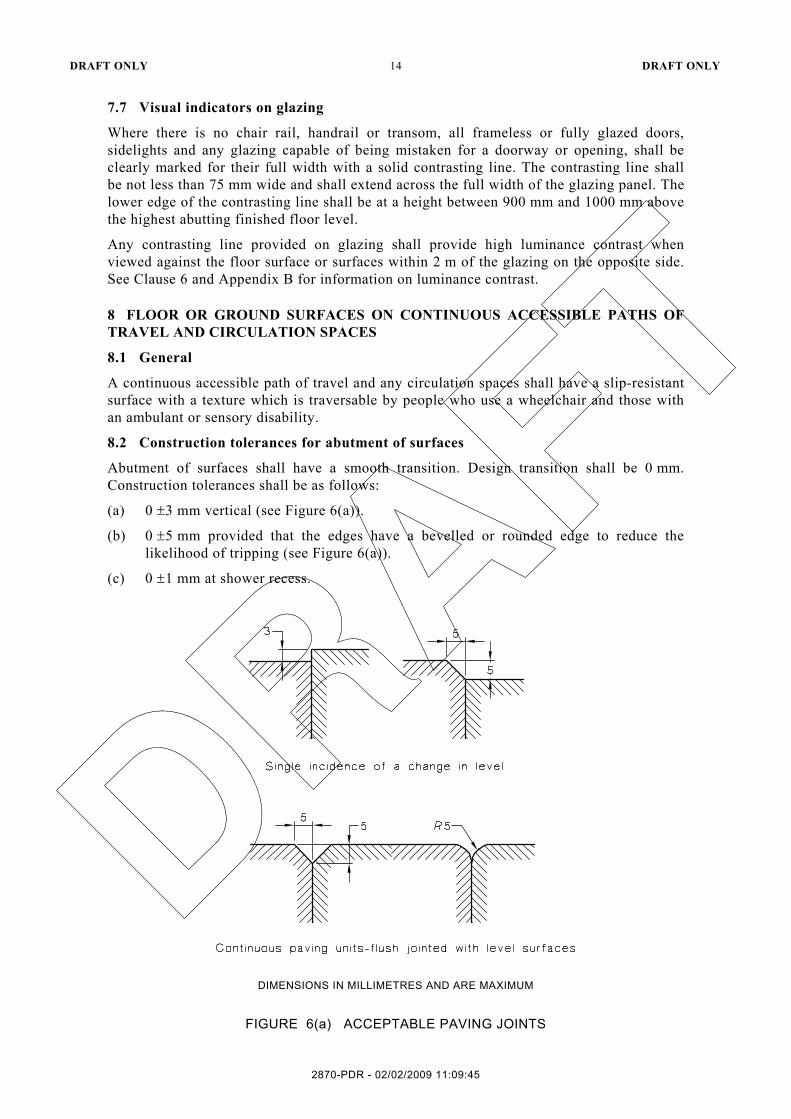
8.2 Construction tolerances for abutment of surfaces
Abutment of surfaces shall have a smooth transition. Design transition shall be 0 mm. Construction tolerances shall be as follows:
(a) 0 ±3 mm vertical (see Figure 6(a)).
(b) 0 ±5 mm provided that the edges have a bevelled or rounded edge to reduce the likelihood of tripping (see Figure 6(a)).
(c) 0 ±1 mm at shower recess.
DIMENSIONS IN MILLIMETRES AND ARE MAXIMUM
FIGURE 6(a) ACCEPTABLE PAVING JOINTS
2870-PDR - 02/02/2009 11:09:45

DRAFT ONLY 15 DRAFT ONLY
DIMENSIONS IN MILLIMETRES AND ARE MAXIMUM
FIGURE 6(b) RAKED JOINT PAVERS
8.3 Changes in level
When a vertical change of not more than 5 mm occurs between the abutment of two surfaces along a continuous accessible path of travel, such change in surface level shall comply with the tolerances given in Clauses 7.2 and 7.3.
When the vertical change in level between the abutment of two surfaces along a continuous accessible path of travel is greater than 5 mm one of the following shall be provided—
(a) a threshold ramp (Clause 11.6);
(b) step ramp (Clause 11.7);
(c) kerb ramp (Clause 11.8);
(d) a ramp (Clause 11.3);
(e) walkway, (Clause 11.2); or
(f) a lift.
2870-PDR - 02/02/2009 11:09:45

DRAFT ONLY 16 DRAFT ONLY
8.4 Fixed or recessed floor coverings—Soft floor coverings
8.4.1 Carpets and other soft flexible materials
Where carpets or any soft flexible materials are used on a ground or floor surface—
(a) the pile height shall be not more than 6 mm;
(b) exposed edges of floor covering shall be fastened to the floor surface and shall have a trim along the entire length of any exposed edge as in Figure 7; and
(c) at the leading edges, carpet trims and any soft flexible materials shall have a vertical face no higher than 3 mm or a rounded bevelled edge no higher than 5 mm or above that height a gradient of 1:8 up to a total maximum height of 10 mm.
2870-PDR - 02/02/2009 11:09:45

DRAFT ONLY 17 DRAFT ONLY
NO
TE:
Abu
tting
flo
r co
verin
gs s
houl
d of
fer
sim
ilar
leve
ls o
f sl
ip r
esis
tanc
e. t
he d
ynam
ic c
oeff
icie
nt o
f fr
ictio
n of
the
adj
acen
t su
rfac
es a
s m
easu
red
in a
ccor
danc
e w
ithA
S/N
ZS 4
586
shou
ld n
ot d
iffer
by
mor
e th
an o
ne c
ateg
ory
as sp
ecifi
ed in
Tab
le 2
or T
able
5, e
.g.,
no m
ore
than
W to
X o
r R9
to R
10. D
iffer
ence
s as g
reat
as W
to Y
or R
9 to
R11
wou
ld re
rega
rded
as p
oten
tially
haz
ardo
us, p
artic
ular
ly if
the
mat
eria
ls a
re v
isua
lly si
mila
r.
FIG
UR
E 7
E
XA
MP
LE O
F A
BU
TTIN
G F
LOO
R C
OV
ER
ING
S O
N A
CO
NTI
NU
OU
S A
CC
ES
SIB
LE P
AR
T O
F TR
AV
EL
2870-PDR - 02/02/2009 11:09:45

DRAFT ONLY 18 DRAFT ONLY
8.4.2 Recessed matting
Matting recessed within a continuous accessible path of travel—
(a) where of metal and bristle type construction or similar, its surface shall be no more 3 mm if vertical or 5 mm if rounded or bevelled, above or below the surrounding surface; and
(b) if of a mat or carpet type material have the fully compressed surface level with or above the surrounding surface with a level difference no greater than 3 mm if vertical or 5 mm if rounded or bevelled.
8.5 Paving
The construction tolerances and profiles for pavers with abutting joints shall be in accordance with Clause 8.2 and Figure 6(a).
Raked joint paving and profiles shall be in accordance with Figure 6(b).
Cobble stones, heavily textured or rounded surfaces or the like shall not be used on an accessible path of travel.
8.6 Grates
Grates shall comply as follows:
(a) Circular openings shall be not more than 13 mm diameter.
(b) Slotted openings shall be not more than 13 mm wide nor more than 150 mm long and be oriented so that the long dimension is transverse to the dominant direction of travel.
(c) Where slotted openings are than 8 mm wide or less, the length of the slots can continue across the width of paths of travel.
9 SIGNAGE
9.1 Form of signs
Where required form of signs shall be as follows:
(a) Elements of a sign shall be set out singularly, or in a modular form as shown in Figures 8(a) and 8(b).
(b) Where a symbol does not exist (see Clause 8.2), facilities shall be identified by the use of English words between 1200 mm to 1600 mm above finished floor levels (see Figure 8(c)).
(c) All symbols and text shall be raised tactile. All text shall also be provided in Braille.
(d) Where required, raised tactile and or Braille signage shall be provided as follows:
(i) Unisex accessible sanitary facilities shall be identified with the international symbol of access and male and female symbols.
(ii) Signage shall be provided with the letters LH or RH to indicate a left hand or right hand side transfer onto the WC pan. The minimum font size shall be 20 mm Sans Serif. An example of right hand side (RH) transfer is shown on Figure 44.
(iii) Entry doors to airlocks serving areas containing sanitary facilities shall be identified—
(A) with a symbol identifying each sanitary facility within. One symbol for each facility need only be used; and
2870-PDR - 02/02/2009 11:09:45

DRAFT ONLY 19 DRAFT ONLY
(B) where the facilities are separate, a dividing line should be placed between
each symbol.
(e) A sanitary compartment for people with ambulant disabilities shall be identified in accordance with Figure 8(d).
(f) Elements of a sign shall be arranged horizontally or vertically, except that, where words are used, they shall be displayed horizontally. NOTE: The BCA contains requirements for Braille and tactile signage in specification D3.6.
FIGURE 8 (in part) MODULAR FORM OF SIGNS
2870-PDR - 02/02/2009 11:09:45

DRAFT ONLY 20 DRAFT ONLY
FIGURE 8 (in part) MODULAR FORM OF SIGNS
9.2 Symbols indicating access for people with disabilities
9.2.1 International symbol of access
The form of the international symbol of access shall be as follows:
(a) The symbol of access shall consist of two elements, viz., a stylized Figure in a wheelchair pointing to the right and a plain square background.
(b) The proportional layout of the symbol of access shall be in accordance with Figure 9.
(c) The colour of the Figure shall be white on a blue background in accordance with Figure 10. The blue shall be B21, ultramarine of AS 2700, or similar.
(d) For signs indicating the direction to a facility, an arrow shall be used in combination with the international symbol of access.
(e) Signs identifying a facility can be used either with or without directional arrows.
2870-PDR - 02/02/2009 11:09:45

DRAFT ONLY 21 DRAFT ONLY
NOTE: The grid is for positional purposes only.
FIGURE 9 PROPORTIONAL LAYOUT FOR INTERNATIONAL SYMBOL OF ACCESS
FIGURE 10 COLOUR CONTRASTING FOR SYMBOL OF ACCESS
9.2.2 International symbol for deafness
The form of the international symbol for deafness shall be as follows:
(a) The symbol for deafness shall consist of two elements, viz., a stylized ear and diagonal slash on a plain square background.
(b) The proportional layout of the symbol for deafness shall be in accordance with Figure 11.
(c) The colour of the symbol shall be white on a blue background. The blue shall be B21, ultramarine of AS 2700, or similar.
2870-PDR - 02/02/2009 11:09:45

DRAFT ONLY 22 DRAFT ONLY
NOTE: The grid is for positional purposes only.
FIGURE 11 PROPORTIONAL LAYOUT FOR INTERNATIONAL SYMBOL FOR DEAFNESS
10 TACTILE GROUND SURFACE INDICATORS
Where required by regulatory authorities, TGSI’s shall be provided to warn people of hazards (see AS/NZS 1428.4.1).
11 WALKWAYS, RAMPS AND LANDINGS
11.1 General
Walkways, ramps and landings provided on a continuous accessible path of travel shall be as follows:
(a) Sharp transitions shall be provided between the planes of landings and ramps (see Figure 12).
(b) Landings shall be provided at all changes in direction except where allowed in Clause 11.5.
(c) Landing or circulation space shall be provided at every doorway, gate, or the like.
(d) For walkways and landings having gradients in the direction of travel shallower than 1 in 33, a camber or crossfall shall be provided for shedding of water and shall be no steeper than 1:40 except that bitumen surfaces shall have a camber or crossfall no steeper than 1:33. (For requirements for ground surfaces, see Clause 8.)
11.2 Walkways
Walkways shall comply with the following:
(a) The floor or ground surface abutting the sides of the walkway shall follow the grade of the walkway and shall extend horizontally for a minimum of 600 mm unless one of the following is provided:
(i) Kerb and handrail in accordance with Figure 17.
(ii) Kerbrail and handrail in accordance with Figure 18.
(iii) A wall not less than 450 mm in height.
2870-PDR - 02/02/2009 11:09:45
DRAFT ONLY 23 DRAFT ONLY
(b) Walkways shall be provided with landings as specified in Clause 11.5 at intervals not
exceeding the following:
(i) For walkway gradients of 1 in 33............................................................... 25 m.
(ii) For walkway gradients of 1 in 20............................................................... 15 m.
(iii) For walkway gradients between 1 in 20 to 1:33, at intervals that shall be obtained by linear interpolation.
(iv) For walkways shallower than 1 in 33, no landings are required.
(c) The intervals in Item (b) may be increased by 30% where at least one side of a walkway is bounded by—
(i) a kerb as specified in Clause 11.3(j) and a handrail as specified in Clause 11.3(i); or
(ii) a wall and a handrail as specified in Clause 13.
11.3 Ramps
Ramps shall comply with the following:
(a) The maximum gradient of a ramp exceeding 1900 mm in length shall be 1 in 14.
(b) The gradient of a ramp shall be constant throughout its length with a maximum allowable tolerance of 3% provided that no section of the ramp is steeper than 1 in 14.
(c) Ramps shall be provided with landings as specified in Clause 11.6 at the bottom and at the top of the ramp and at intervals not exceeding the following:
(i) For ramp gradients of 1 in 14.......................................................................9 m.
(ii) For ramp gradients of steeper than 1 in 20 ................................................. 15 m.
(iii) For ramp gradients between 1 in 14 and steeper than 1 in 20 at intervals which shall be obtained by linear interpolation.
(d) Where ramps are constructed with a change in direction the angle of approach shall create a 90° angle to the line of transition between the ramp surface and the landing surface as shown in Figure 12.
(e) Ramps shall have a handrail complying with Clause 13 on each side of the ramp, as shown in Figures 13 and 14.
(f) Where the intersection is at the property boundary, the ramp shall be set back by a minimum of 900 mm so that the handrail (complying with Clause 13) and TGSIs do not protrude into the transverse path of as shown in Figure 15.
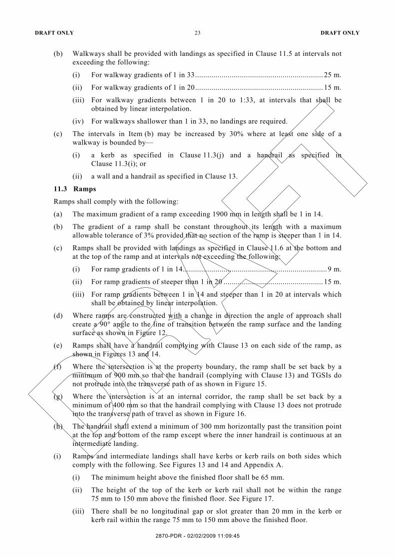
(g) Where the intersection is at an internal corridor, the ramp shall be set back by a minimum of 400 mm so that the handrail complying with Clause 13 does not protrude into the transverse path of travel as shown in Figure 16.
(h) The handrail shall extend a minimum of 300 mm horizontally past the transition point at the top and bottom of the ramp except where the inner handrail is continuous at an intermediate landing.
(i) Ramps and intermediate landings shall have kerbs or kerb rails on both sides which comply with the following. See Figures 13 and 14 and Appendix A.
(i) The minimum height above the finished floor shall be 65 mm.
(ii) The height of the top of the kerb or kerb rail shall not be within the range 75 mm to 150 mm above the finished floor. See Figure 17.
(iii) There shall be no longitudinal gap or slot greater than 20 mm in the kerb or kerb rail within the range 75 mm to 150 mm above the finished floor.
2870-PDR - 02/02/2009 11:09:45

DRAFT ONLY 24 DRAFT ONLY
(j) Kerbs or kerb rails shall—
(i) be located so that the ramp-side face is either flush with the ramp-side face of the handrail or no greater than 100 mm away from the ramp-side face of the handrail. See Figure 18; or
(ii) where the handrail is supported on a vertical post, the height of the top of the kerb or kerb rail shall be not less than 150 mm above the finished floor. See Figures 18(i), 18(ii) or 18(iii); and
(iii) where the kerb is at a height of 65 mm to 75 mm, the support posts shall be set back a minimum of 200 mm from the face of the kerb or kerb rail. See Figure 18(iv).
2870-PDR - 02/02/2009 11:09:45

DRAFT ONLY 25 DRAFT ONLY
DIM
EN
SIO
NS
IN M
ILLI
ME
TRE
S
FIG
UR
E 1
2 A
NG
LE O
F A
PP
RO
AC
H B
ETW
EE
N R
AM
P A
ND
LA
ND
ING
2870-PDR - 02/02/2009 11:09:45

DRAFT ONLY 26 DRAFT ONLY
DIMENSIONS IN MILLIMETRES
FIGURE 13 PLAN VIEW-RAMP HANDRAILS
DIMENSIONS IN MILLIMETRES
FIGURE 14 RAMP HANDRAILS
2870-PDR - 02/02/2009 11:09:45

DRAFT ONLY 27 DRAFT ONLY
FIGURE 15 LOCATION OF RAMP AT A BOUNDARY TO PREVENT PROTRUSION OF HANDRAILS AND TACTILE GROUND SURFACE INDICATORS (TGSIs)
INTO A TRANSVERSE PATH OF TRAVEL
2870-PDR - 02/02/2009 11:09:45
DRAFT ONLY 28 DRAFT ONLY
FIGURE 16 LOCATION OF RAMP TO PREVENT PROTRUSION OF HANDRAILS INTO A TRANSVERSE PATH OF TRAVEL OTHER THAN AT BOUNDARIES
2870-PDR - 02/02/2009 11:09:45

DRAFT ONLY 29 DRAFT ONLY
DIMENSIONS IN MILLIMETRES
FIGURE 17 KERBS RAILS
NOTE: See Appendix A for further clarification.
DIMENSIONS IN MILLIMETRES
FIGURE 18 SECTION SHOWING LOCATION OF KERB OR KERB RAIL IN RELATION TO HANDRAIL WITH VERTICAL SUPPORT
2870-PDR - 02/02/2009 11:09:45

DRAFT ONLY 30 DRAFT ONLY
11.4 Curved walkways, ramps, and landings
Curved ramps, walkways and landings shall comply with the following:
(a) The gradient of curved ramps and walkways shall comply with Figure 19.
(b) Landings shall comply with Clause 11.5.
(c) The length of a curved ramp shall be measured horizontally along its centre-line.
(d) Curved ramps and walkways shall have a width of not less than 1500 mm.
(e) Any crossfall shall be towards the centre of curvature.
DIMENSIONS IN MILLIMETRES
FIGURE 19 CURVED RAMP AND WALKWAY GRADIENTS
11.5 Landings
11.5.1 Walkways and ramps
The length of landings at walkways (up to a gradient of 1 in 33) and ramps shall be—
(a) not less than 1200 mm where there is no change in direction (see Figure 20(a)); or
(b) not less than 1500 mm where there is a change of direction not exceeding 90°. The internal corner shall be truncated for a minimum of 500 mm in both directions (see Figure 20(b)); or
(c) as shown in Figures 5(c) and 20(c) for a 180° turn.
Where doorways are at landings, the dimensions of the landings shall be in accordance with the requirements for circulation spaces at doorways in Clause 14.3 (see Figure 20(d)).
2870-PDR - 02/02/2009 11:09:45

DRAFT ONLY 31 DRAFT ONLY
11.5.2 Step ramps
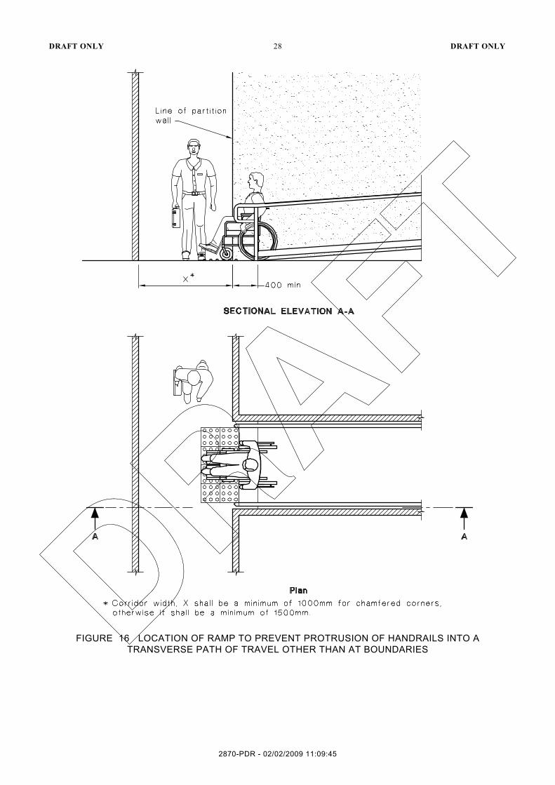
The length of landings at step ramps shall not be less than 1200 mm in the direction of travel (see Figure 22(a) and 22(b)).
Where a change in direction is required, the length of step ramp landings shall be a minimum of 1500 mm (see Figure 22(a) and (b)).
Where doorways are at landings, the dimensions of the landings shall be in accordance with the requirements for circulation spaces at doorways in Clause 14.3 (see Figure 20(d)).
11.5.3 Kerb ramps
The length of landings at kerb ramps shall be not less than 1200 mm in the direction of travel (see Figure 24(c)).
Where a change in direction is required, the length of kerb ramp landings shall be a minimum of 1500 mm (see Figure 24(a) and (b)).
2870-PDR - 02/02/2009 11:09:45

DRAFT ONLY 32 DRAFT ONLY
DIM
EN
SIO
NS
IN M
ILLI
ME
TRE
S
FIG
UR
E 2
0(a)
R
AM
PS
AN
D L
AN
DIN
GS
—W
ITH
NO
CH
AN
GE
IN D
IRE
CTI
ON
2870-PDR - 02/02/2009 11:09:45

DRAFT ONLY 33 DRAFT ONLY
DIM
EN
SIO
NS
IN M
ILLI
ME
TRE
S
FIG
UR
E 2
0(b)
R
AM
PS
AN
D L
AN
DIN
GS
—90
° LA
ND
ING
—IN
TER
NA
L
2870-PDR - 02/02/2009 11:09:45

DRAFT ONLY 34 DRAFT ONLY
DIM
EN
SIO
NS
IN M
ILLI
ME
TRE
S
FIG
UR
E 2
0(c)
R
AM
PS
AN
D L
AN
DIN
GS
—18
0° L
AN
DIN
G
2870-PDR - 02/02/2009 11:09:45

DRAFT ONLY 35 DRAFT ONLY
DIMENSIONS IN MILLIMETRES
FIGURE 20 EXAMPLES OF DOORWAYS AT LANDINGS
11.6 Threshold ramps
On a continuous accessible path of travel, a threshold ramp shall have a maximum rise of 35 mm, a maximum length of 280 mm and a maximum gradient of 1 in 8 (see Figure 20).
The edges of the threshold ramp shall be tapered or splayed at a minimum of 45° where it does not abut a wall or kerb. For door controls refer to Clause 14.5.
2870-PDR - 02/02/2009 11:09:45

DRAFT ONLY 36 DRAFT ONLY
DIMENSIONS IN MILLIMETRES
FIGURE 21 RAMPED THRESHOLD
11.7 Step ramps
11.7.1 General
Step ramps shall comply with the following:
(a) Have a maximum rise of 190 mm.
(b) Have a length not greater than 1900 mm.
(c) Have a gradient not steeper than 1:10.
Step ramps shall be as shown in Figures 22(a) and (b), as appropriate.
The edges of step ramp shall have a 45° splay where there is a pedestrian cross traffic. Otherwise, it shall be protected by a suitable barrier (see Figures 22(b)), such as—
(a) a wall or suitable barrier with a minimum height of 450 mm; or
(b) kerb or kerb rail.
2870-PDR - 02/02/2009 11:09:45
DRAFT ONLY 37 DRAFT ONLY
NOTE: Top and bottom landing may be reduced to 1200 mm min. in length where there is no turn involved.
DIMENSIONS IN MILLIMETRES
FIGURE 22(a) INSERTED STEP RAMPS
2870-PDR - 02/02/2009 11:09:45

DRAFT ONLY 38 DRAFT ONLY
DIMENSIONS IN MILLIMETRES
FIGURE 22(b) EXTERNAL STEP RAMP AT ENTRANCE TO BUILDING
2870-PDR - 02/02/2009 11:09:45

DRAFT ONLY 39 DRAFT ONLY
11.7.2 Finishes
Step ramps shall have a slip-resistant surface.
11.8 Kerb ramps
11.8.1 Alignment
Kerb ramps shall be aligned in the direction of travel. See Figure 23.
FIGURE 23 LOCATION OF KERB RAMPS
11.8.2 Profile
Kerb ramps shall comply with the following:
(a) Have a maximum rise of 190 mm.
(b) Have a length not greater than 1520 mm.
(c) Have a gradient not steeper than 1 in 8, located within or attached to a kerb.
The profile of ramps shall comply with the following:
(i) The design and construction of kerb ramps shall be as shown in Figures 24(a), 24(b) and 24(c).
(ii) The edges of a kerb ramp shall be tapered or splayed at 45° or the minimum length of the splay measured along the kerbs shall be 1500 mm.
11.8.3 Finishes
Kerb ramps shall have a slip-resistant surface.
2870-PDR - 02/02/2009 11:09:45

DRAFT ONLY 40 DRAFT ONLY
NOTE: Top landing may be reduced to 1200 mm min. in length where there is no turn involved.
DIMENSIONS IN MILLIMETRES
FIGURE 24(a) INSERTED KERB RAMP
2870-PDR - 02/02/2009 11:09:45

DRAFT ONLY 41 DRAFT ONLY
NOTE: Top landing may be reduced to 1200 mm min. in length where there is no turn involved.
DIMENSIONS IN MILLIMETRES
FIGURE 24(b) ATTACHED KERB RAMP
2870-PDR - 02/02/2009 11:09:45

DRAFT ONLY 42 DRAFT ONLY
DIMENSIONS IN MILLIMETRES
FIGURE 24(c) IN LINE KERB RAMPS—NARROW FOOTPATHS
2870-PDR - 02/02/2009 11:09:45

DRAFT ONLY 43 DRAFT ONLY
12 STAIRWAYS
12.1 Stair construction
Where required, stairs shall be constructed as follows:
(a) Where the intersection is at the property boundary, the stair shall be set back by a minimum of 900 mm so that the handrail (complying with Clause 13) and TGSIs do not protrude into the transverse path of travel (see Figure 25(a)).
(b) Where the intersection is at an internal corridor, the stair shall be set back in accordance with Figure 25(b).
(c) Spiral stairways shall have a minimum going of 250 mm at the line of the inside handrail measured vertically from any point on the handrail.
(d) Stairs shall have opaque risers.
(e) Stair nosings shall not project more than 30 mm past the riser. See Figure 26.
(f) Stair nosing profiles shall have a—
(i) sharp intersection; or
(ii) rounded up to 15 mm radius; or
(iii) chamfered up to 5 mm × 5 mm.
(g) A strip not less than 50 mm and not greater than 75 mm shall be provided on the tread at the nosing with a minimum luminance contrast of 30% to the background.
2870-PDR - 02/02/2009 11:09:45

DRAFT ONLY 44 DRAFT ONLY
DIMENSIONS IN MILLIMETRES
FIGURE 25(a) STAIRWAY LOCATION AND HANDRAIL EXTENSIONS AT BOUNDARY—PLAN VIEW
2870-PDR - 02/02/2009 11:09:45

DRAFT ONLY 45 DRAFT ONLY
FIGURE 25(b) STAIRWAY LOCATION AND HANDRAIL EXTENSIONS AT END OF STAIRWAY OTHER THAN AT LINE OF BOUNDARY
2870-PDR - 02/02/2009 11:09:45

DRAFT ONLY 46 DRAFT ONLY
NOTE: A chamfered nosing 5 × 5 mm may be used.
DIMENSIONS IN MILLIMETRES
FIGURE 26 TYPICAL STAIR NOSING PROFILE
12.2 Stairway handrails
Handrails shall be continuous throughout the stair flight, around landings and have no obstruction on or above up to a height of 600 mm and as follows:
(a) The design and construction of handrails shall comply with Clause 13.
(b) Handrails shall be installed on both sides of the stairs and as shown in Figures 25(a) and 25(b).
(c) Handrails shall have no vertical sections and, wherever practicable, shall be continuous throughout the stair flights and around landings (see Figure 27).
(d) If the handrail cannot be continuous and where TGSIs are not required, a raised tactile warning in the form of a domed button with a height of 4 mm to 5 mm and a diameter of 10 mm to 12 mm shall be provided on the top of the handrail 150 ±10 mm from the end of the handrail.
(e) Where a handrail terminates at the bottom of a flight of stairs, the handrail shall extend at least one tread depth parallel to the line of nosings plus 300 mm horizontally from the last riser (see Figure 25(b)).
(f) The handrail must extend a minimum of 300 mm horizontally past the nosing on the top riser.
(g) The 300 mm extension is not required in the inner handrail at intermediate landings.
(h) The dimensions indicating the heights of handrails shall be taken vertically from the nosing of the tread to the top of the handrail.
2870-PDR - 02/02/2009 11:09:45

DRAFT ONLY 47 DRAFT ONLY
DIMENSIONS IN MILLIMETRES
FIGURE 27 INSIDE HANDRAIL AT LANDINGS
2870-PDR - 02/02/2009 11:09:45

DRAFT ONLY 48 DRAFT ONLY
13 HANDRAILS
The design and construction of handrails shall comply with the following:
(a) Handrails and balustrades shall not encroach into required circulation spaces.
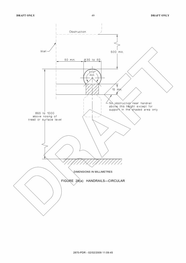
(b) The cross-section of handrails shall be circular or elliptical not less than 30 mm in height nor more than 50 mm in width for not less than 270° around the uppermost surface. The major axis shall be the horizontal dimension. See Figures 28(a) and 28(b).
(c) Exposed edges at ends and corners of handrails shall have a radius of not less than 5 mm.
(d) The top of handrails shall be not less than 865 mm nor more than 1000 mm above the nosing of stairway tread or the plane of the finished floor of the walkway, ramp or landing.
(e) The height of the top of the handrail, measured in accordance with Item (c), shall be consistent through the ramp (or stairs) and any landings.
(f) If a balustrade is required at a height greater than the handrail, both shall be provided.
(g) Handrails shall be securely fixed and rigid, and their ends shall be turned through a total of 180°, or to the ground, or returned fully to end post or wall face (see Figures 25(a) and 25(b)). The fastenings and the materials and construction of handrails shall be able to withstand forces in accordance with AS/NZS 1170.1.
(h) The clearance between a handrail and an adjacent wall surface or other obstruction shall be not less than 50 mm. This clearance shall extend above the top of the handrail by not less than 600 mm.
(i) Handrails shall have no obstruction to the passage of a hand along the rail (see Figures 28(a) and 28(b)).
(j) The inside handrail at landings shall always be continuous (see Figure 27).
2870-PDR - 02/02/2009 11:09:45
DRAFT ONLY 49 DRAFT ONLY
DIMENSIONS IN MILLIMETRES
FIGURE 28(a) HANDRAILS—CIRCULAR
2870-PDR - 02/02/2009 11:09:45

DRAFT ONLY 50 DRAFT ONLY
DIMENSIONS IN MILLIMETRES
FIGURE 28(b) HANDRAILS—ELLIPTICAL
14 DOORWAYS, DOORS AND CIRCULATION SPACE AT DOORWAYS
14.1 Luminance contrast
Doors forming part of an accessible path of travel shall have a high luminance contrast provided between—
(a) door and door jamb;
(b) door and adjacent wall;
(c) architrave and wall; or
(d) door and architrave.
The minimum width of the area of luminance contrast shall be 50 mm.
2870-PDR - 02/02/2009 11:09:45

DRAFT ONLY 51 DRAFT ONLY
14.2 Visual indicators at glazed doors and sidelights
See Clause 6.8.
14.3 Clear opening of doorways
The minimum clear opening of a doorway on a continuous accessible path of travel shall be 850 mm when measured from the face of the opened door to the door stop (see Figure 29). Refer to Clause 14.5 for door controls.
DIMENSIONS IN MILLIMETRES
FIGURE 29 CLEAR OPENING OF DOORWAYS
14.4 Circulation spaces at doorways on a continuous accessible path of travel
14.4.1 General
Circulation spaces shall be provided at every doorway, gate, or the like on a continuous accessible path of travel.
Circulation spaces at doorways shall have a gradient not steeper than 1 in 40.
Doorway circulation spaces shall be used in combination to allow access through doorways in both directions. See Figures 30 and 31.
The dimensions shall also apply in mirror image configurations. Intermediate sizes shall be interpolated.
14.4.2 Swinging doors
The clear circulation space at doorways with swinging doors is based on the clear opening width of the doorway (D). The clear circulation space shall be not less than the dimensions specified in the tables in Figure 24 for the appropriate clear opening width.
2870-PDR - 02/02/2009 11:09:45

DRAFT ONLY 52 DRAFT ONLY
DIMENSIONS IN MILLIMETRES
FIGURE 30 (in part) CIRCULATION SPACES AT DOORWAYS WITH SWINGING DOORS
2870-PDR - 02/02/2009 11:09:45

DRAFT ONLY 53 DRAFT ONLY
DIMENSIONS IN MILLIMETRES
FIGURE 30 (in part) CIRCULATION SPACES AT DOORWAYS WITH SWINGING DOORS
2870-PDR - 02/02/2009 11:09:45

DRAFT ONLY 54 DRAFT ONLY
DIMENSIONS IN MILLIMETRES
FIGURE 31 CIRCULATION SPACES AT DOORWAYS WITH SWINGING AND SLIDING DOORS
2870-PDR - 02/02/2009 11:09:45

DRAFT ONLY 55 DRAFT ONLY
14.4.3 Sliding doors
14.4.3.1 Cavity sliding doors
Where a sliding door is within the wall cavity, the circulation space at the doorway shall be not less than that given in the tables in Figure 30 for the appropriate clear opening width (D). Where a sliding door is automatic, for a front on approach the WL and WH dimensions do not apply.
14.4.3.2 Surface-mounted doors
Where a sliding door is surface-mounted, the circulation space at the doorway shall be as follows:
(a) The circulation space at the door face shall be not less than that given in the tables in Figure 31.
(b) The circulation space opposite the door face shall be increased from that given in the tables in Figure 31, by the values given in the Table in Figure 32. When a surface-mounted sliding door is automatic, these increases do not apply.
NOTE: See Clause 14.2 for clear openings of doorways.
FIGURE 32 CALCULATING DIMENSIONS OF THE CIRCULATION SPACE OPPOSITE THE DOOR FACE WHERE A SLIDING DOOR IS SURFACE-MOUNTED
14.4.4 Automatic doors
To permit a wheelchair to turn through a door from a side-on approach, dimension WL or WH are required on the approach side only.
For location of manual controls for automatic doors, see Clause 14.5.3.
14.5 Distance between successive doorways in passages in an accessible path of travel
The distance between doorways in vestibules, air locks and other similarly enclosed spaces shall be not less than 1450 mm unless the doors encroach into the space, in which case the distance shall be not less than 1450 mm plus the door leaf width (see Figure 33) or are in compliance with Figures 30 or 31, as applicable.
2870-PDR - 02/02/2009 11:09:45

DRAFT ONLY 56 DRAFT ONLY
DIMENSIONS IN MILLIMETRES
FIGURE 33 DISTANCE BETWEEN SUCCESSIVE DOORWAYS IN VESTIBULES AND AIR LOCKS ON A CONTINUOUS ACCESSIBLE PATH OF TRAVEL
14.6 Door controls
14.6.1 General
Door controls in or forming part of the continuous accessible path of travel shall comply with the requirements of this Clause.
14.6.2 Design and performance
Door handles and related hardware and accessories shall comply with the following:
(a) The door handle and related hardware shall be of the type that allows the door to be unlocked and opened with one hand. The handle shall be such that the hand of a person who cannot grip will not slip from the handle during the operation of the latch. Door handles of ‘D’ lever type provide an adequate grip for people with hand impairments. Figures 34(a) and 34(b) show an example of a suitable hinged door handle and Figure 34(c) shows an example of a suitable door handle for sliding doors.
FIGURE 34(a) EXAMPLE OF ACCEPTABLE DOOR HARDWARE FOR HINGED DOORS—ISOMETRIC
2870-PDR - 02/02/2009 11:09:45

DRAFT ONLY 57 DRAFT ONLY
FIGURE 34(b) ACCEPTABLE DOOR HARDWARE FOR HINGED DOORS—PLAN VIEW
2870-PDR - 02/02/2009 11:09:45

DRAFT ONLY 58 DRAFT ONLY
FIG
UR
E 3
4(c)
E
XA
MP
LE O
F A
CC
EP
TAB
LE D
OO
R H
AR
DW
AR
E F
OR
SLI
DIN
G D
OO
RS
2870-PDR - 02/02/2009 11:09:45

DRAFT ONLY 59 DRAFT ONLY
(b) The clearance between the D-lever type handle and the back plate or door face at the
centre grip section of the handle shall be not less than 35 mm and not more than 45 mm.
(c) ‘D’-type handles shall be provided on sliding doors with a minimum clearance of 35 mm from the face of the door.
(d) Where provided, ‘D’-type handles shall have a minimum clearance of 35 mm from the face of the door.
(e) Where snibs are installed, they shall have a lever handle of a minimum length of 45 mm from the centre of the spindle.
(f) For doors other than fire doors and smoke doors where a door closer is fitted, the force required to operate the door shall not exceed the following (see Figure 35):
(i) To initially open the door .......................................................................... 20 N.
(ii) To swing the door...................................................................................... 20 N.
(iii) To hold the door open between 60° and 90°............................................... 20 N.
FIGURE 35 FORCES REQUIRED FOR OPERATING DOORS
(g) Where door closers are used on a continuous accessible path of travel, devices such as power operated on demand doors, adjustable delayed action multi-sized door closers, rising-butt hinges and the like shall be used.
(h) Where an outward opening door is not self-closing, a horizontal handrail or pull bar shall be fixed on the closing face of a side-hung door, as shown in Figure 36.
2870-PDR - 02/02/2009 11:09:45

DRAFT ONLY 60 DRAFT ONLY
DIMENSIONS IN MILLIMETRES
FIGURE 36 LOCATIONS FOR DOOR CONTROLS SHOWING CLOSING FACE
14.6.3 Location
Except in early childhood centres and swimming pool barriers where the location of the opening and locking controls is prescribed by the relevant statutory authority, the location of the controls for doors and gates shall be as follows:
(a) Controls that need to be grasped or turned shall be not less than 900 mm no more than 1100 mm above the plane of the finished floor (see Figure 36).
(b) Controls that only need to be pushed, such as manual controls for pedestrian powered doors, panic bars on egress routes, shall be not less than 900 mm, nor more than 1200 mm above the plane of the finished floor.
(c) Handles on sliding doors shall be not less than 60 mm from the door jamb or door stop when in the open or closed position (see Figure 37).
(d) Manual controls to power operated doors shall be located on the continuous accessible path of travel no closer than 500 mm from an internal corner and between 1000 mm to 2000 mm from the hinged door leaf in any position or clear of a surface mounted sliding door in the open position.
DIMENSIONS IN MILLIMETRES
FIGURE 37 LOCATION FOR HANDLES ON SLIDING DOORS
2870-PDR - 02/02/2009 11:09:45

DRAFT ONLY 61 DRAFT ONLY
15 SWITCHES AND GENERAL PURPOSE OUTLETS (POWER POINTS)
15.1 General
All switches required to be accessible, other than general purpose outlets, shall be located not less than 900 mm nor more than 1100 mm above the plane of the finished floor and not less than 500 mm from internal corners except where on the architrave on the latch side (see Figure 38).
15.2 Accessible sole-occupancy units and accessible sanitary facilities
Where required, rocker action and toggle switches shall have a minimum dimension of 30 mm × 30 mm and push pad switches shall have a minimum dimension of 25 mm in diameter.
General purpose outlets shall be located not less than 600 mm nor more than 1100 mm above the plane of the finished floor and not less than 500 mm from internal corners.
DIMENSIONS IN MILLIMETRES
FIGURE 38 HEIGHTS FOR SWITCHES AND DOOR HANDLES
16 SANITARY FACILITIES
16.1 General
The facilities described in this Clause may be used as individual modules, in mirror image configurations or in a combined form (see Clause 16.6).
Where the floor of a sanitary facility other than a shower recess has a floor waste, the floor shall be self draining and have a grade between 1 in 80 and 1 in 100 (see Figure 39).
2870-PDR - 02/02/2009 11:09:45

DRAFT ONLY 62 DRAFT ONLY
DIMENSIONS IN MILLIMETRES
FIGURE 39 RECOMMENDED GRADES FOR BATHROOM AND SHOWER FLOORS
16.2 Accessible unisex sanitary facilities
16.2.1 General
The following general requirements shall apply:
(a) An accessible unisex sanitary facility is one which is available for use by both sexes and located so that access does not necessitate traversing an area reserved for one sex only.
(b) A hand-washing facility shall be provided inside the toilet cubicle and shall form part of the accessible unisex facility, see Clause 16.3.
16.2.2 Water taps
Water taps shall comply with the following:
(a) Taps shall have lever handles or sensor plate controls or the like.
(b) Lever handles shall have not less than 50 mm clearance from an adjacent surface.
(c) Where separate taps are provided for hot and cold water, the hot water tap shall be placed to the left of the cold water tap for horizontal configurations, or above the cold water tap for vertical configurations.
(d) Where hot water is provided, the water shall be delivered through a mixing spout.
16.2.3 WC pan clearances
WC pan clearances, and set out, seat height and seat width shall be as shown in Figure 40.
2870-PDR - 02/02/2009 11:09:45

DRAFT ONLY 63 DRAFT ONLY
NOTES: 1 For the purpose of dimensioning, the front of the WC pan has been taken as the datum plane. 2 The dimension of 800 ± 10 mm from the front of the WC pan to the wall is a critical dimension.
DIMENSIONS IN MILLIMETRES
FIGURE 40 WATER CLOSET PAN CLEARANCES, SEAT HEIGHT AND SEAT WIDTH
16.2.4 Seat
The toilet seat shall comply with the following:
(a) Be of the full-round type, (i.e., not open fronted) and with minimal contours to the top surface.
(b) Be securely fixed in position when in use.
(c) Have seat fixings which create lateral stability for the seat when in use.
(d) Be load rated to 150 kg.
(e) Have a high level of luminance contrast with the background, e.g., pan, wall or floor against which it is viewed.
16.2.5 Backrest
A backrest shall be provided and comply with the following:
(a) Be able to withstand a force in any direction of 1100 N.
(b) Height of the lower edge of backrest above the pan—120 mm to 150 mm, see Figure 41(a).
(c) Backrest to have a vertical height of 150–200 mm and a width of 350–400 mm, see Figure 41(b).
(d) The front edge of the centre of the backrest to be positioned to achieve an angle of between 100° to 105° back from the seat hinge.
2870-PDR - 02/02/2009 11:09:45

DRAFT ONLY 64 DRAFT ONLY
FIGURE 41(a) SEMI-RECESSED WASHBASIN INSTALLATION—OTHER THAN FOR SOLE-OCCUPANCY UNIT
2870-PDR - 02/02/2009 11:09:45

DRAFT ONLY 65 DRAFT ONLY
FIGURE 41(b) WALL MOUNTED WASHBASIN INSTALLATION
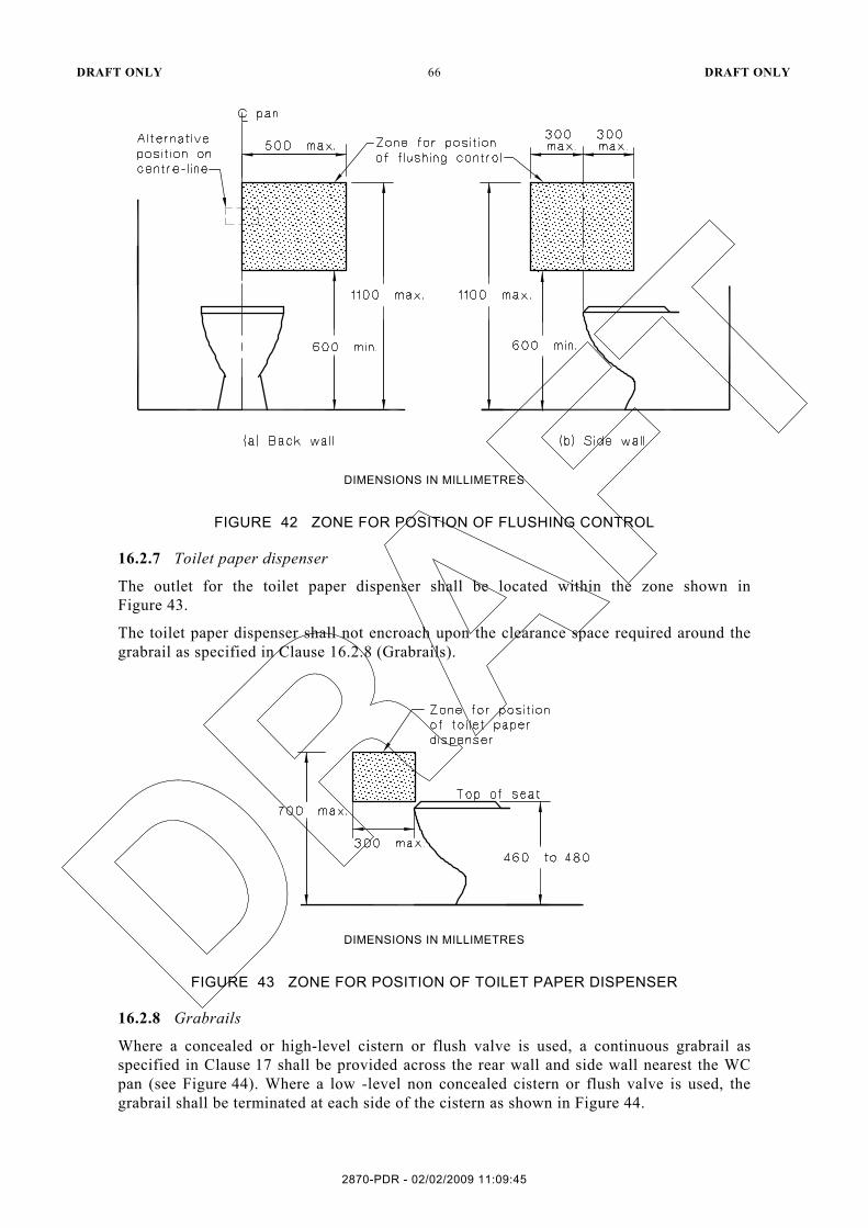
16.2.6 Flushing control
Flushing controls shall be user activated, either hand operated or automatic. Where hand operated flushing controls are used, they shall be located within the zone shown in Figure 42, or centred on the centre-line of the toilet, wholly within the vertical limits of that zone. The position of the flushing control within this zone shall not be within the area required for any grabrails. The flushing control shall be proud of the surface and shall activate the flush before the button becomes level with the surrounding surface.
2870-PDR - 02/02/2009 11:09:45
DRAFT ONLY 66 DRAFT ONLY
DIMENSIONS IN MILLIMETRES
FIGURE 42 ZONE FOR POSITION OF FLUSHING CONTROL
16.2.7 Toilet paper dispenser
The outlet for the toilet paper dispenser shall be located within the zone shown in Figure 43.
The toilet paper dispenser shall not encroach upon the clearance space required around the grabrail as specified in Clause 16.2.8 (Grabrails).
DIMENSIONS IN MILLIMETRES
FIGURE 43 ZONE FOR POSITION OF TOILET PAPER DISPENSER
16.2.8 Grabrails
Where a concealed or high-level cistern or flush valve is used, a continuous grabrail as specified in Clause 17 shall be provided across the rear wall and side wall nearest the WC pan (see Figure 44). Where a low -level non concealed cistern or flush valve is used, the grabrail shall be terminated at each side of the cistern as shown in Figure 44.
2870-PDR - 02/02/2009 11:09:45

DRAFT ONLY 67 DRAFT ONLY
NOTE: Grabrails shall comply with Clause 16.2.8.
DIMENSIONS IN MILLIMETRES
FIGURE 44 POSITIONS OF GRABRAILS IN WATER CLOSETS
2870-PDR - 02/02/2009 11:09:45

DRAFT ONLY 68 DRAFT ONLY
16.2.9 Circulation space in WCs
For each WC, the unobstructed circulation space from the finished floor to a height of not less than 2000 mm shall be as shown in Figures 43 and 44 with the following exceptions:
(a) The WC pan and cistern and flush valve (see Clauses 16.2.3 and 16.2.6).
(b) The toilet paper dispenser (see Clause 16.2.7).
(c) Grabrails (see Clause 16.2.8).
(d) Washbasin limited to 100 mm intrusion as shown in Figure 46(a).
(e) Hand dryers and towel dispensers.
(f) Soap dispensers (see Clause 16.4.3).
(g) Shelves (see Clause 16.4.2).
(h) Where provided, wall cabinets shall be mounted at least 900 above floor level and have the top shelf a maximum of 1250 above floor level. Wall cabinets shall not protrude greater than 150 mm into the circulation space.
(i) Clothes hanging devices (see Clause 16.4.4).
(j) Portable sanitary disposal unit as shown in Figure 45.
(k) Other wall mounted fixtures which shall be 900 mm minimum height clearance from the finished floor level with a maximum projection of 150 mm from finished wall surface such as dispensing units and sharps disposal units.
All other items such as baby change tables, baby napkin bins, shall be stored outside the required circulation spaces.
The overlapping of circulation spaces shall be in accordance with Clause 16.6.
2870-PDR - 02/02/2009 11:09:45

DRAFT ONLY 69 DRAFT ONLY
NOTE: This circulation space can overlap any other circulation spaces specified in this Standard.
DIMENSIONS IN MILLIMETRES
FIGURE 45 CIRCULATION SPACE FOR WC PAN-RIGHT HAND TRANSFER (LEFT HANDED TRANSFER IS MIRROR REVERSED)
16.2.10 WC doors
WC doors to sanitary facilities shall comply with the following:
(a) Doors may be either hinged or sliding.
(b) Outward-opening doors shall have a mechanism that holds the door in a closed position without the use of a latch.
(c) Doors shall be provided with an in-use indicator and a bolt or catch. Where a snib catch is used, the snib handle shall have a minimum length of 45 mm from the centre of the spindle. The latch mechanism shall be openable from the outside in an emergency.
(d) The force required to operate the door shall be in accordance with Clause 14.5.2.
2870-PDR - 02/02/2009 11:09:45

DRAFT ONLY 70 DRAFT ONLY
(e) Door handles and hardware shall be in accordance with Clause 14.5.
(f) Each doorway shall have unobstructed circulation space in accordance with Clause 14 for access and egress.
16.3 Washbasins
16.3.1 General
The installation of washbasins shall comply with the following:
(a) Water taps shall comply with Clause 16.2.2.
(b) Exposed hot water supply pipes shall be insulated or located so as not to present a hazard.
(c) The projection of the washbasin from the wall and the position of taps, bowl and drain outlet shall be determined in accordance with the requirements shown in Figure 46(a) and 46(b), except in sole-occupancy units, where Figure 47 shall be used.
(d) Water supply pipes and waste outlet pipes shall not encroach on the required clear space under the washbasin.
(e) For each washbasin fixture, the unobstructed circulation space shall be as shown in Figure 48 except in sole occupancy units where Figure 47 shall be used. The washbasin fixture and its fittings are the only fixtures permitted in this space.
2870-PDR - 02/02/2009 11:09:45

DRAFT ONLY 71 DRAFT ONLY
DIM
EN
SIO
NS
IN M
ILLI
ME
TRE
S
FIG
UR
E 4
6(a)
S
EM
I-R
EC
ES
SE
D W
AS
HB
AS
IN IN
STA
LLA
TIO
N—
OTH
ER
TH
AN
FO
R S
OLE
-OC
CU
PA
NC
Y U
NIT
2870-PDR - 02/02/2009 11:09:45

DRAFT ONLY 72 DRAFT ONLY
DIM
EN
SIO
NS
IN M
ILLI
ME
TRE
S
FIG
UR
E 4
6(b)
W
ALL
MO
UN
TED
WA
SH
BA
SIN
INS
TALL
ATI
ON
—O
THE
R T
HA
N F
OR
SO
LE-O
CC
UP
AN
CY
UN
IT
2870-PDR - 02/02/2009 11:09:45

DRAFT ONLY 73 DRAFT ONLY
16.3.2 Accessible sole occupancy units
Accessible sole occupany units shall have the following characteristics:
(a) The projection of the washbasin from the wall and the position of taps, bowl and drain outlet shall be determined in accordance with the requirements shown in Figure 46.
(b) Water supply pipes and waste outlet pipes shall not encroach on the required clear space under the washbasin (see Figure 47).
(c) For each washbasin fixture, the unobstructed circulation space shall be as shown in Figure 48. The washbasin fixture and its fittings are the only fixtures permitted in this space.
(d) Shelf space shall be provided adjacent to the basin in one of the following ways:
(i) As a vanity top at a height of 800 mm to 830 mm and a minimum width of 120 mm and a minimum depth of 300 mm without encroaching into any knee and toe clearance space for a minimum width of 850 mm centred on the basin.
(ii) As a separate fixture—
(A) within any circulation space at a height of 900 mm to 1000 mm with a minimum underside clearance of 850 mm for a width of 120 mm to 150 mm and length of 300 mm to 400 mm; and
(B) external to all circulation spaces at a height of 800 mm to 1000 mm with a minimum width of 120 mm and minimum length of 400 mm.
2870-PDR - 02/02/2009 11:09:45

DRAFT ONLY 74 DRAFT ONLY
DIM
EN
SIO
NS
IN M
ILLI
ME
TRE
S
FIG
UR
E 4
7 W
AS
HB
AS
IN F
OR
AC
CE
SS
IBLE
SO
LE O
CC
UP
AN
Y U
NIT
2870-PDR - 02/02/2009 11:09:45

DRAFT ONLY 75 DRAFT ONLY
NOTE: This circulation space may overlap any other circulation spaces specified in this Standard.
DIMENSIONS IN MILLIMETRES
FIGURE 48 CIRCULATION SPACE FOR WASHBASINS
16.4 Fixtures and fittings within a sanitary facility
16.4.1 Mirrors
Where provided, a vertical mirror with a reflective surface not less than 350 mm wide shall extend from a height of not more than 900 mm to a height of not less than 1850 mm above the plane of the finished floor. A second vertical mirror, where provided, shall extend from a height of not less than 600 mm to a height of not less than 1800 mm above the plane of the finished floor.
In an accessible sole occupancy unit, the mirror shall be centred over the washbasin.
16.4.2 Shelves
Shelf space shall be provided adjacent to the basin in one of the following ways:
(a) As a vanity top at a height of 800 mm to 830 mm and a minimum width of 120 mm and depth of 300 mm to 400 mm without encroaching into any circulation space.
(b) As a separate fixture—
(i) within any circulation space at a height of 900 mm to 1000 mm with a width of 120 mm to 150 mm and length of 300 mm to 400 mm; and
(ii) external to all circulation spaces at a height of 790 mm to 1000 mm with a minimum width of 120 mm and minimum length of 400 mm.
16.4.3 Soap dispensers, towel dispensers and the like
Where provided, soap dispensers, towel dispensers, hand dryers and similar fittings shall be installed with the height of their operative component or outlet not less than 900 mm and not more than 1100 mm above the plane of the finished floor and shall be operable by one hand.
2870-PDR - 02/02/2009 11:09:45

DRAFT ONLY 76 DRAFT ONLY
DIMENSIONS IN MILLIMETRES
FIGURE 49 SHOWER RECESS AND CIRCULATION SPACE—PLAN
2870-PDR - 02/02/2009 11:09:45

DRAFT ONLY 77 DRAFT ONLY
DIMENSIONS IN MILLIMETRES
FIGURE 50 SHOWER RECESS FITTINGS—ELEVATION
16.4.4 Clothes-hanging devices
A clothes-hanging device shall be installed 1200 mm to 1350 mm above the plane of the finished floor and not less than 500 mm out from any internal corner except where associated with shower recesses configured as shown in Figure 48 when at least one shall be placed on the return wall within reach of a person seated on the folding seat.
16.4.5 Sanitary disposal unit
Where provided, the sanitary disposal unit shall be located as follows:
(a) Portable unit as shown in Figure 45.
(b) Recessed unit within 500 mm from the pan.
16.4.6 Switches and general purpose outlets
Where provided near the washbasin, switches and general purpose outlets shall be located in accordance with Clause 15 and as close to the shelf or worktop as practicable.
16.5 Showers
16.5.1 General
The general requirements for showers are as follows:
(a) Shower recesses and the circulation space for each shower recess from the finished floor to a height of not less than 900 mm shall be as shown in Figure 48. Grabrails, shower hose fittings and the folding seat are the only fixtures permitted in these spaces.
2870-PDR - 02/02/2009 11:09:45

DRAFT ONLY 78 DRAFT ONLY
(b) Shower recess fittings shall be provided as shown in Figures 49 and 50. Not less than
two clothes-hanging devices as specified in Clause 16.4.4 shall be fitted outside the shower recess. One such device shall be located within 600 mm of the folding seat.
(c) If two or more shower recesses are provided, at least one shall be of the opposite hand.
16.5.2 Floor and waste outlet
The requirements for the floor and waste outlet are as follows:
(a) The floor of the shower recess and associated circulation space shall be self-draining and without a step down, raised step kerb or hob at the entry to the recess.
(b) The waste outlet for the shower shall be provided in accordance with Figure 48.
(c) The slope of the floor of the shower recess shall have a gradient between 1 in 60 and 1 in 80 (see Figure 39).
(d) The slope of floor of the remainder of the sanitary facility shall have a gradient between 1 in 80 and 1 in 100 (see Figure 39).
16.5.3 Opening shower screens
The means of screening a shower recess shall be either by a curtain or a door system that maintains the required circulation space of 1600 mm × 2350 mm.
16.5.4 Grabrails
Grabrails as specified in Clause 17 shall be fixed on the walls in the positions shown in Figures 49 and 50. Taps, soap holder and shower head support grabrail as shown in Figures 49 and 50 may encroach into the 600 mm clearance above the grabrail required in Clause 17(e).
16.5.5 Shower head support grabrail
A shower head support grabrail in accordance with Clause 17 shall be fixed on the wall in the position shown in Figure 50.
16.5.6 Shower head
A hand held shower head shall be provided which has a flexible hose of a minimum length of 1200 mm and is able to reach within 100 mm of the shower floor.
An adjustable shower head holder shall be provided to support the shower head and which complies with the following:
(a) Be installed on the shower head holder support grabrail as shown in Figure 50.
(b) Allow the graspable portion of the shower head to be positioned at various angles and heights.
(c) Allow the graspable portion of the shower head to be located at heights between 1000 mm and 1800 mm above the plane of the finished floor.
16.5.7 Soap holder
The soap holder shall be located within the zone shown in Figure 50.
16.5.8 Taps
Taps as specified in Clause 16.2.2 shall be located within the zone shown in Figure 50.
16.5.9 Folding seat
A foldable seat shall be provided inside the shower recess (see Figures 49 and 50) and have the following features—
(a) be self-draining;
2870-PDR - 02/02/2009 11:09:45
DRAFT ONLY 79 DRAFT ONLY
(b) be slip-resistant;
(c) have front corners that are rounded to a radius of 10 to 15 mm;
(d) have top edges that are rounded with a minimum radius of 2 to 3 mm; and
(e) shall fold in an upwards direction and when folded—
(i) the seat shall not present a hazard; and
(ii) the grabrail shall be accessible.
Where drainage is provided by holes or slots in single unit seats or by gaps between slats in compound seats, the diameter of the holes, the width of the slots and the gaps between slats shall be between 4 to 6 mm.
The fastenings, materials and construction of the seat shall be able to withstand a force of 1100 N applied at any position and in any direction without failing or loosening of fastenings.
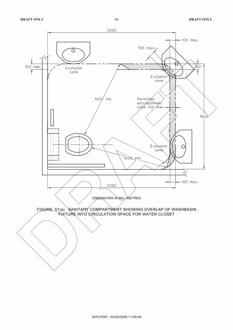
16.6 Circulation spaces in accessible sanitary facilities
Accessible sanitary facilities shall contain circulation spaces in accordance with Clause 16.2.8 and Figures 45, 46, 47, 48, 49 and 50. The following shall also apply:
(a) Circulation spaces, including door circulation spaces, may be overlapped.
(b) With the following exceptions, fixtures shall not encroach into circulation spaces:
(i) The washbasin may encroach into the WC circulation space in accordance with Figure 51(a).
(ii) The washbasin may encroach into the shower circulation space in accordance with Figure 51(b).
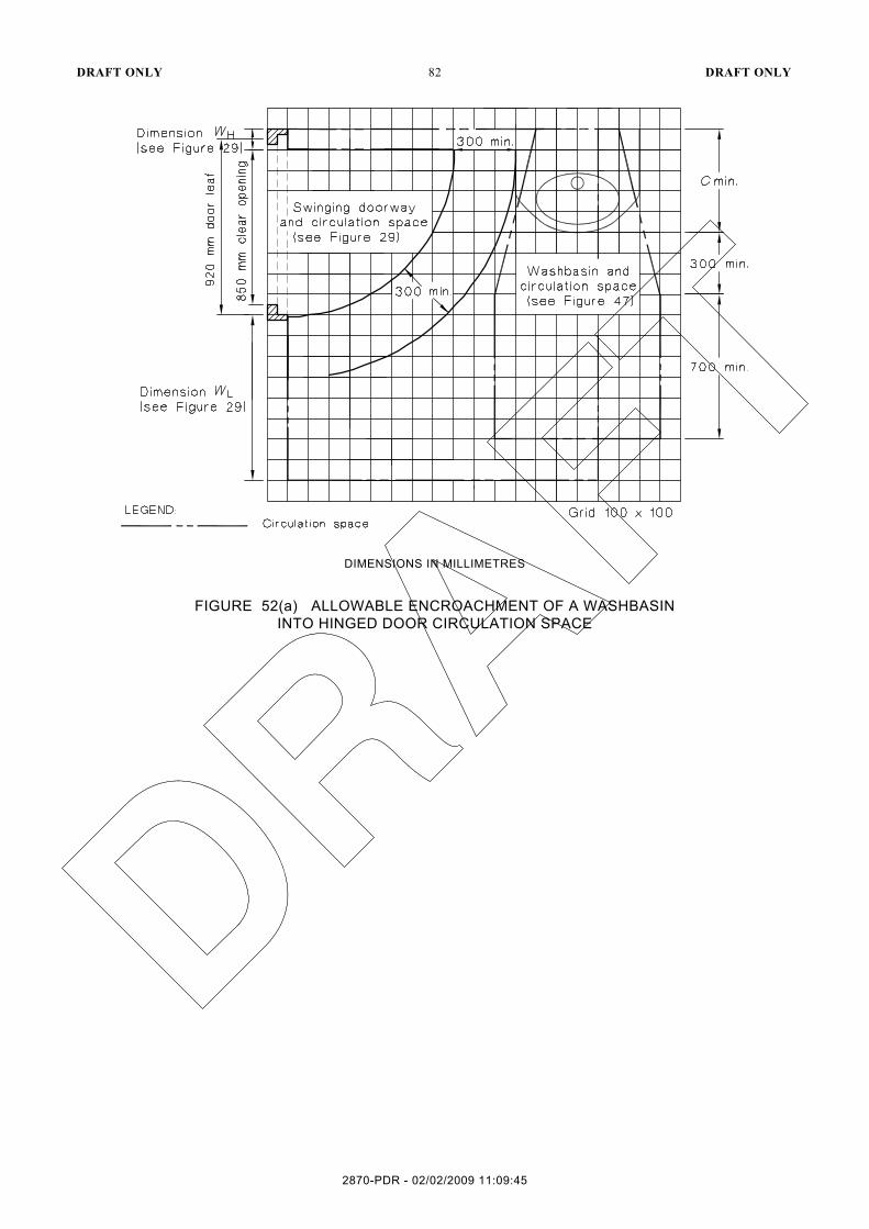
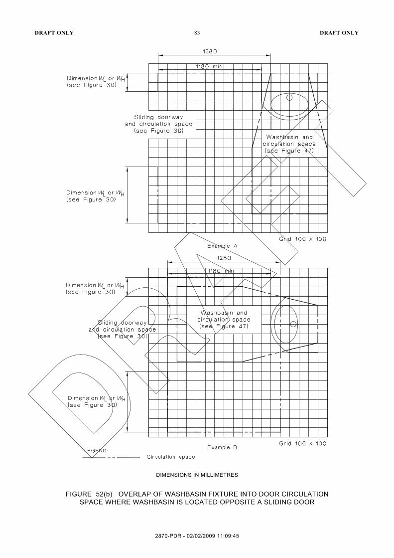
(iii) The washbasin may encroach into the circulation space of the door in accordance with Figures 52(a) and 52(b).
2870-PDR - 02/02/2009 11:09:45
DRAFT ONLY 80 DRAFT ONLY
DIMENSIONS IN MILLIMETRES
FIGURE 51(a) SANITARY COMPARTMENT SHOWING OVERLAP OF WASHBASIN FIXTURE INTO CIRCULATION SPACE FOR WATER CLOSET
2870-PDR - 02/02/2009 11:09:45

DRAFT ONLY 81 DRAFT ONLY
FIGURE 51(b) SANITARY COMPARTMENT SHOWING OVERLAP OF WASHBASIN FIXTURE INTO SHOWER CIRCULATION SPACE
2870-PDR - 02/02/2009 11:09:45
DRAFT ONLY 82 DRAFT ONLY
DIMENSIONS IN MILLIMETRES
FIGURE 52(a) ALLOWABLE ENCROACHMENT OF A WASHBASIN INTO HINGED DOOR CIRCULATION SPACE
2870-PDR - 02/02/2009 11:09:45
DRAFT ONLY 83 DRAFT ONLY
DIMENSIONS IN MILLIMETRES
FIGURE 52(b) OVERLAP OF WASHBASIN FIXTURE INTO DOOR CIRCULATION SPACE WHERE WASHBASIN IS LOCATED OPPOSITE A SLIDING DOOR
2870-PDR - 02/02/2009 11:09:45

DRAFT ONLY 84 DRAFT ONLY
Clearances beneath the washbasin shall be maintained in accordance with Clause 16.3 and door circulation spaces shall be maintained in accordance with Clause 14.3 modified in accordance with Item (b)(ii) or (iii) of this Clause, if appropriate. For examples of overlapping circulation spaces in sanitary facilities, see Figures 51, 52 and 53.
NOTES: 1 As a design aid for combining sanitary facilities, transparent overlays of modules of each
sanitary facility with its minimum circulation space, which are based on Figures 45, 48 and 49 are included with this Standard. The transparencies are as follows: (a) Transparency No. 1, WC and circulation space.................................. based on Figure 45. (b) Transparency No. 2, washbasin and circulation space ........................ based on Figure 48. (c) Transparency No. 3, two-walled shower recess and circulation space ..................... based
on Figure 49. 2 Overlays for spatial requirements at doorways are not included and these should be drawn up
by the designer as appropriate from the data given in Figures 30 and 31, as appropriate. 3 Worked examples of accessible sanitary facilities, using the design aid overlays, are given in
Appendix C.
DIMENSIONS IN MILLIMETRES
FIGURE 53 EXAMPLES OF OVERLAPPING CIRCULATION SPACES IN A SANITARY COMPARTMENT
2870-PDR - 02/02/2009 11:09:45

DRAFT ONLY 85 DRAFT ONLY
16.7 Sanitary compartment for people with ambulant disabilities
16.7.1 General
Sanitary compartment for people with ambulant disabilities shall be in accordance with Figures 54 and 55.
16.7.2 Grabrails
Grabrails shall be installed in accordance with Clause 17 and Figure 54.
16.7.3 Doors
Doors to sanitary compartments for people with ambulant disabilities shall have openings with a minimum clear width of 700 mm and comply with Figure 55.
Doors shall be provided with an in-use indicator and a bolt or catch. Where a snib catch is used, the snib handle shall have a minimum length of 45 mm from the centre of the spindle. The latch mechanism shall be openable from the outside in an emergency.
Doors shall have a hinge mechanism that holds the door in a closed position.
16.7.4 Signage
Sanitary compartment for people with ambulant disabilities shall be identified by symbol or words, see Clause 8.
16.7.5 Coat hook
A coat hook shall be provided within the sanitary compartment and at a height between 1350 mm to 1500 mm from the floor.
2870-PDR - 02/02/2009 11:09:45

DRAFT ONLY 86 DRAFT ONLY
DIMENSIONS IN MILLIMETRES
FIGURE 54 SANITARY COMPARTMENT FOR PEOPLE WITH AMBULANT DISABILITIES
2870-PDR - 02/02/2009 11:09:45

DRAFT ONLY 87 DRAFT ONLY
FIGURE 55 SANITARY COMPARTMENT FOR PEOPLE WITH AMBULANT DISABILITIES DOORWAY OPTIONS
2870-PDR - 02/02/2009 11:09:45

DRAFT ONLY 88 DRAFT ONLY
17 GRABRAILS
Grabrails shall comply with the following:
(a) Grabrails shall be not less than 30 mm and not more than 40 mm outside diameter, or they shall have a sectional shape within the limits of 30 mm to 40 mm diameter.
(b) Exposed edges and corners of grabrails shall have a radius of not less than 5 mm.
(c) The fastenings and the materials and construction of grabrails shall be able to withstand a force of 1100 N applied at any position and in any direction without deformation or loosening or rotation of the fastenings or fittings.
(d) The clearance between a grabrail and the adjacent wall surface or other obstruction shall be not less than 50 mm and not more than 60 mm. The clearance above a horizontal grabrail shall extend above the top of the grabrail by not less than 600 mm. The clearance below a horizontal or angled rail shall be a minimum of 50 mm except at fixing points.
(e) Grabrails shall be fixed so that there is no obstruction to the passage of the hand along the top 270° of horizontal and angled grabrails. It does not apply to vertical grabrails or vertical parts of grabrails.
18 ASSEMBLY BUILDINGS
18.1 Wheelchair seating spaces
Where fixed seating is provided, wheelchair seating spaces shall be as follows:
(a) Adjacent to, and on the same level as, other seating in the row and shall be part of a continuous accessible path of travel.
(b) Located to allow lines of sight comparable to those for general viewing areas and shall not be obstructed by opaque handrails or balustrades. NOTE: Wheelchair seating spaces may be achieved by providing removable seating.
18.2 Surfaces
The ground or floor at wheelchair seating spaces shall be level when internal or have a gradient not steeper than 1 in 40 where external.
18.3 Spatial requirements
The minimum space for each wheelchair shall be as shown in Figure 56(a). The whole of the space allocated for any wheelchair shall not impinge on the dimensions required for aisles by more than 250 mm, or for crossovers by more than 300 mm.
2870-PDR - 02/02/2009 11:09:45
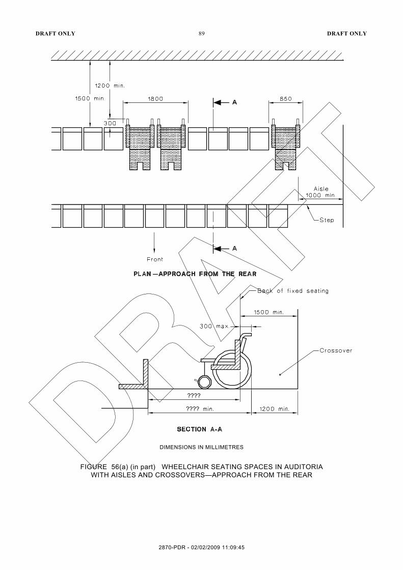
DRAFT ONLY 89 DRAFT ONLY
DIMENSIONS IN MILLIMETRES
FIGURE 56(a) (in part) WHEELCHAIR SEATING SPACES IN AUDITORIA WITH AISLES AND CROSSOVERS—APPROACH FROM THE REAR
2870-PDR - 02/02/2009 11:09:45

DRAFT ONLY 90 DRAFT ONLY
DIMENSIONS IN MILLIMETRES
FIGURE 56(b) (in part) WHEELCHAIR SEATING SPACES IN AUDITORIA WITH AISLES AND CROSSOVERS—APPROACH FROM THE FRONT
2870-PDR - 02/02/2009 11:09:45

DRAFT ONLY 91 DRAFT ONLY
DIMENSIONS IN MILLIMETRES
FIGURE 56(c) (in part) WHEELCHAIR SEATING SPACES IN AUDITORIA WITH CONTINENTAL SEATING (i.e., NO AISLES OR CROSSOVERS)
2870-PDR - 02/02/2009 11:09:45

DRAFT ONLY 92 DRAFT ONLY
APPENDIX A
EXAMPLES OF KERBS
(Informative)
The kerb and handrail configurations shown in Figure A1 comply with the requirements of Clause 11.3(j).
DIMENSIONS IN MILLIMETRES
FIGURE A1 (in part) TYPES OF KERBS
2870-PDR - 02/02/2009 11:09:45
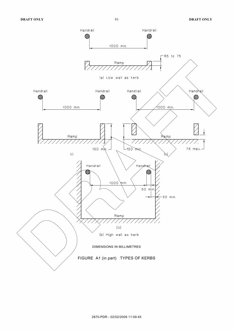
DRAFT ONLY 93 DRAFT ONLY
DIMENSIONS IN MILLIMETRES
FIGURE A1 (in part) TYPES OF KERBS
2870-PDR - 02/02/2009 11:09:45

DRAFT ONLY 94 DRAFT ONLY
APPENDIX B
THE MEASUREMENT OF LUMINANCE CONTRAST BETWEEN BUILDING ELEMENTS
(Informative)
B1 GENERAL
This Appendix sets out two methods for measuring the luminance contrast between building elements, in a laboratory or on-site.
Where it is necessary to achieve sufficient luminance contrast between building elements, this can usually be achieved by using very dark or very light materials. The luminance contrast is achieved by measuring the luminous reflectance of the 1st building element and comparing it with the luminous reflectance of the 2nd building element in accordance with Paragraphs B3 and B4 or B5.
B2 LUMINANCE CONTRAST REQUIREMENTS
Luminance contrast between building elements is the difference in the amount of light reflected (luminance reflectance) from the 1st building element compared to the amount of light reflected from the 2nd building element.
The 1st building elements shall have a minimum luminance contrast of 30% compared to the amount of light reflected from the 2nd building element.
It may be necessary to test both elements when wet and dry.
The test to be conducted both may be carried out in the laboratory and on-site, and for published results to then be compared.
B3 MEASUREMENT OF LUMINANCE CONTRAST—LABORATORY
B3.1 General
This Paragraph sets out a method for measuring the luminous reflectance of building elements. The method is carried out with reference to a standard light source, which is an inherent feature of suitable colorimeters and spectrophotometers.
NOTE: Some buildings materials manufacturers do publish luminous reflectance values for each of their products.
This test method is not suitable for measuring the luminous reflectance of translucent materials or illuminated objects. It is less applicable where the measured surface is not uniformly coloured.
NOTE: The method specifies colorimeters and spectrophotometers that are widely available.
B3.2 Instrumentation
A tristimulus colorimeter or spectrophotometer with a diffuse illumination/normal viewing (d/o) geometry, shall be used with CIE Standard Illuminant D65. The instrument should be capable of measuring absolute CIE Yxy to be calculated. The measured luminous reflectance is defined by the tristimulus value Y. The chromaticity coordinates x and y provide an indication of the colour.
B3.3 Procedure
The procedure shall be as follows:
(a) Calibrate the equipment in accordance with the manufacturer’s instructions.
2870-PDR - 02/02/2009 11:09:45

DRAFT ONLY 95 DRAFT ONLY
(b) Locate the equipment on the surface to be measured.
(c) Make measurements in at least five locations (on each building element) or on five units of the product (such as samples, where five units are available). Where the surface does appear (visually) to be uniformly coloured, a minimum of 10 measurements shall be taken. Record the luminous reflectance (Y value) for each individual dry measurement that is made. The luminous reflectance ‘Y’ value of the CIE 1964 colour system is recognized in AS/NZS 1580.601.2.
(d) Unless wet measurements are deemed to be inappropriate, wet the surface of the product and ensure that the surface remains wet (such that water ponds on the surface) for a minimum of 5 min. Make measurements as in Step (c), as soon as possible after removing any unabsorbed water from the surface with a cloth or sponge that does not leave any solid residue. Record the luminous reflectance (Y value) for each individual wet measurement that is made.
Determine the mean dry luminous reflectance Yd and the mean wet luminous reflectance Yw. NOTES: 1 The use of standardized illumination conditions when making photometer measurements
could enable manufacturers to publish luminous reflectance values that are consistent with those obtained using this Appendix.
2 For standard colours, see AS 2700.
The luminous contrast (C) of two surfaces shall be calculated using the following equation:
( )( )21
12
0.5 YYYYC+
−=
where
C = luminance contract
Y1 and Y2 = luminous reflectance values of the two surfaces
B3.4 Report
The following shall be reported:
(a) Full description of the surfaces tested with product details where known.
(b) The instrument geometry, the light source as being D65, the aperture and the observer angle.
(c) The locations of the measurements on the sample.
(d) The mean luminous reflectance of the building elements under the conditions set out in Paragraph B3.3.
(e) A reference to this test method, i.e., AS/NZS 1428.4, Paragraph E3, Appendix E.
The corresponding data for other light sources and illuminant may also be reported.
B4 DETERMINATION OF LUMINANCE CONTRAST
This Clause sets out a method of using the luminous reflectance values to calculate the required minimum luminance contrast between two adjacent or contiguous surfaces when the luminous reflectance of the products are known is based on the following equation:
( )( ) 30.0
0.5 21
12 =+
−=
YYYYC
2870-PDR - 02/02/2009 11:09:45
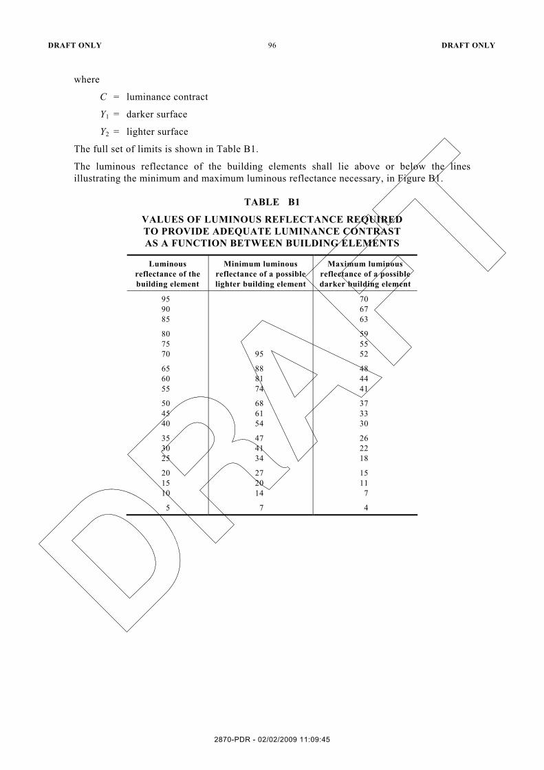
DRAFT ONLY 96 DRAFT ONLY
where
C = luminance contract
Y1 = darker surface
Y2 = lighter surface
The full set of limits is shown in Table B1.
The luminous reflectance of the building elements shall lie above or below the lines illustrating the minimum and maximum luminous reflectance necessary, in Figure B1.
TABLE B1
VALUES OF LUMINOUS REFLECTANCE REQUIRED TO PROVIDE ADEQUATE LUMINANCE CONTRAST AS A FUNCTION BETWEEN BUILDING ELEMENTS
Luminous reflectance of the building element
Minimum luminous reflectance of a possible lighter building element
Maximum luminous reflectance of a possible darker building element
95 90 85
70 67 63
80 75 70
95
59 55 52
65 60 55
88 81 74
48 44 41
50 45 40
68 61 54
37 33 30
35 30 25
47 41 34
26 22 18
20 15 10
27 20 14
15 11
7
5 7 4
2870-PDR - 02/02/2009 11:09:45

DRAFT ONLY 97 DRAFT ONLY
FIGURE B1 LIMITING VALUES OF LUMINOUS REFLECTANCE OF BUILDING ELEMENTS
B5 MEASUREMENT OF LUMINANCE CONTRAST—ON-SITE
B5.1 General
This Paragraph sets out the method of on-site measurement of contrast of building elements. This method is carried out under the prevailing lighting condition(s) and is also applicable where a building element is not uniformly coloured.
NOTE: The method specifies a luminance meter (photometer) with a 1° measurement field. Such meters are widely available. While a wider field of view such as 3° may be preferable because it permits a shorter measurement distance, luminance meters with wider fields are less common and substantially more expensive.
B5.2 Instrumentation
A single lens reflex luminance meter commonly known as a photometer with a 1° measurement field and a spectral responsivity approximating the CIE 1931 Standard Observer V (λ) function as specified in ISO CIE 10527 shall be used.
B5.3 Procedure
The procedure shall be as follows:
(a) Mount the luminance meter on a tripod so that the centre of the objective lens is at a height of 1.6 ±0.1 m (representative of the eye height of a standing person).
(b) Locate the tripod so that measurements can be made of both building elements without moving the tripod. Direct the luminance meter to the point where the width of the smaller building element just fills the measurement field. Choose an area that is visually uniformly lit. Record the luminance L1.
(c) Direct the luminance meter to measure the 2nd building element immediately adjacent to the previous location of the 1st building. Record the luminance L2.
2870-PDR - 02/02/2009 11:09:45

DRAFT ONLY 98 DRAFT ONLY
(d) If either building element is highly coloured, correct any significant deviation from
the CIE V(λ) function by measuring the luminance of a white plate (La) direct and then through a filter (Lb) with nominally the same chromaticity as the building element and known luminous transmittance ( )τ . Where the correction factor F is defined as follows:
τ×=b
a
LLF
(e) When calculating the contrast between the building element use the appropriate following equation:
2
1212 thenIf
LLLCLL −
=>
1
2121 thenIf
LLLCLL −
=>
Compliance is established using C as appropriate.
(f) To carry out wet measurements make measurements in at least five locations (on each building element) or on five units of the product (such as samples where five units are available). Where the surface does not appear (visually) to be uniformly coloured, a minimum of 10 measurements shall be taken. Record the luminance reflectance (L value) for each individual dry measurement that is made. The luminance reflectance L value of the CIE 1964 colour system is recognized in AS/NZS 1580.601.2.
(g) Unless wet measurements are deemed to be inappropriate, wet the surface of the product and ensure that the surface remains wet (such that water ponds on the surface) for a minimum of 5 min. Make measurements as in step c as soon as possible after removing any unabsorbed water from the surface with a cloth or sponge that does not leave any solid residue. Record the luminous reflectance (Y value) for each individual wet measurement that is made. Determine the mean dry luminous reflectance Ld and the mean wet luminous reflectance Lw. NOTES: 1 The use of standardized illumination conditions when making photometer measurements
could enable manufacturers to publish luminous reflectance values that are consistent with those obtained using this Appendix.
2 For standard colours, see AS 2700.
B5.4 Report
The following shall be reported:
(a) Full description of the building elements with product details where known.
(b) The instrument being a luminance meter with a 1° measurement area corrected to approximate the CIE 1931 Standard Observer.
(c) The location of the sample, if on-site.
(d) The location of the sample of the measurements on the 1st building element.
(e) A description of the light source(s) illuminating the sample, including type, e.g., fluorescent tube, incandescent, high pressure sodium discharge, metal halide, and colour (in general terms).
(f) The mean luminance reflectance of the 2nd building element to the 1st building element under the conditions set out in Paragraph B5.3.
2870-PDR - 02/02/2009 11:09:45

DRAFT ONLY 99 DRAFT ONLY
(g) The mean luminance reflectance of the 1st building element to the 2nd building
element under the conditions set out in Paragraph B5.3.
(h) The luminance contrast with the 2nd building element.
(i) A reference to this test method, i.e., AS/NZS 1428.4, Paragraph B5, Appendix B.
(j) Where the lighting source varies, e.g., by night and day, the corresponding data for other light sources may also be reported.
*** END OF DRAFT ***
2870-PDR - 02/02/2009 11:09:45