Embed Size (px)
Citation preview

Starting screen for Google Sketchup
Sketchup is used to make 3 dimensional objects3 axis – Green is x axis
Red is y axisBlue is z axis

Use Eraser tool – Click on Eraser Icon on top menu Click Eraser on Lady
Lady is gone

We want to make this shape in Google Sketchup
Start by making a solid block and then chiseling away
Identify the total length, width, and height of the object
Total length is 4”
Total width is 1.5”
Total height is 2.5”

Start by making rectangle for the base of the object1. Click on rectangle icon
on the top toolbar2. Move cursor until it hovers over the origin

Start by making rectangle for the base of the object
3. Click once on the origin and drag the rectangle in red/green plane, but don’t
click the mouse
4. Type in dimensions of the base as 4”,1.5”. The dimensions will appear
on bottom right hand box as you type. Click enter when you are done typing.

Use zoom tools to make objects bigger1. The rectangle will appear for the base, and is going to be extremely
small.
2. Move cursor to zoom extents icon on top
toolbar and then click icon

Use zoom tools to make objects bigger
3. Sketchup zooms in to fill the screen
4. Use pan tool to lower rectangle on the
screen
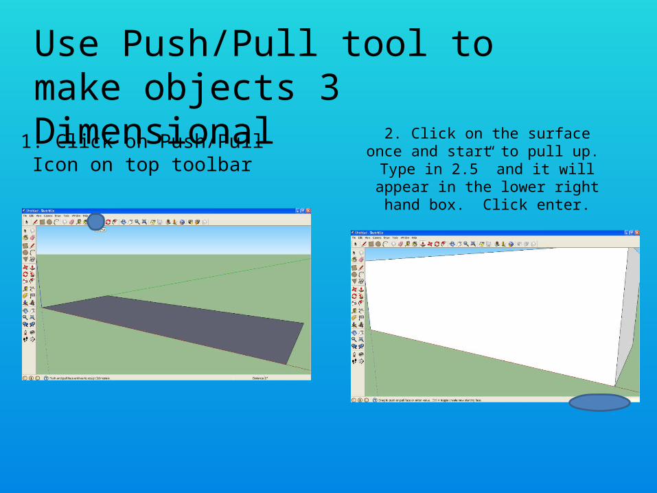
Use Push/Pull tool to make objects 3 Dimensional
1. Click on Push/Pull Icon on top toolbar
2. Click on the surface once and start to pull up. Type in 2.5”
and it will appear in the lower right hand box. Click enter.

Use Push/Pull tool to make objects 3 Dimensional
3. Click Zoom Extents to zoom out to see complete object
4. Use orbit tool to rotate object to see front, right
and top faces.

Use tape measure tool to mark distances
1. Click on the tape measure icon on the top toolbar
2. Click on the point that you want to measure from. For this figure use the top right
corner of the front view.

Use tape measure tool to mark distances
3. After clicking move the cursor down along the blue axis. Type
¾” and click enter.
4. A guide point will appear ¾” below the
top right corner

Use tape measure tool to mark distances
5. Repeat the process, measuring up ¾” from the bottom right corner of the front view. A second guide
point will appear

Use the line tool to make lines in the front face1. Click on the pencil
icon on the top toolbar.2. Move the pencil to the top guide point
and click once

Use the line tool to make lines in the front face
3. Move the pencil straight across the front face. The line will appear in red when it is parallel to the face.
Type in 1” and click enter. Click escape after completing the line
4. Repeat the process for the bottom guide point to make a line parallel to the red axis 1”
long.

Use the line tool to make lines in the front face
5. Complete the region by connecting the endpoints
of the two lines you created

Use Push/Pull to remove region
Remove the region by using push/pull and pushing the
rectangle back to the end of the figure.
Completed figure

Dimensioning figure
1. To dimension a line, select the dimension
option on the Tools Menu
2. To start dimensioning the height of the front view, click
on the bottom left hand corner

Dimensioning figure
3. Move the mouse to the top of the line segment
and click on the endpoint
4. The dimension will appear. Drag the dimension along the red axis and click the mouse.

Dimensioning figure
5. Repeat the process for the left line of the top view.
Pull the dimension up parallel to the blue line.
6. Repeat the process for the back line of the top view. Pull the dimension up parallel to
the blue line.

Dimensioning figure
7. Repeat the process for the dimensions of
the side view.
8. Dimension the empty space on the side view by starting and then ending on the appropriate
points

Dimensioning figure
9. Finish the drawing by dimensioning the final line in the front view