Embed Size (px)
Citation preview

CRD
Kolonay 1
Aeroelastic Optimization
The Cultural and Convention CenterMETU
Inonu bulvariAnkara, Turkey
Sponsored by:RTA-NATO
The Applied Vehicle Technology Panel
presented byR.M. Kolonay Ph.D.
General Electric Corporate Research & Development CenterAnkara, Turkey Oct.. 1-5, 2001
CRD
Kolonay 2
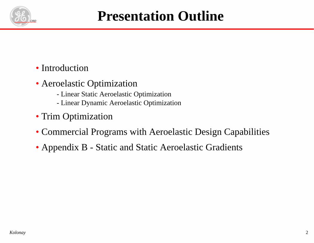
• Introduction
• Aeroelastic Optimization- Linear Static Aeroelastic Optimization- Linear Dynamic Aeroelastic Optimization
• Trim Optimization
• Commercial Programs with Aeroelastic Design Capabilities
• Appendix B - Static and Static Aeroelastic Gradients
Presentation Outline
CRD
Kolonay 3
Motivation for Optimization• Missions of aeronautical and space vehicles are becoming increas-
ingly complex
• Identifying trade-offs among pertinent disciplines is critical inobtaining designs
• Traditional methods may not achieve a design let alone an optimaldesign
• Optimization also used to evaluate/design modifications to existingsystems
Introduction
CRD
Kolonay 4
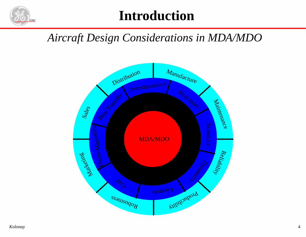
Aircraft Design Considerations in MDA/MDO
Introduction
Distribution
Sal
esM
arke
ting
Aerodynamics
Cost
Heat T
rans
fer
Acoustics
StructuresD
ynamics
Ele
cto-
Mag
netic
s
Controls
Manufacture
Maintenance
Reliability
ProducibilityRobustness
MDA/MDO
CRD
Kolonay 5
Goal of Aeroelastic Optimization
• Determine the aerodynamic and structural parameters to satisfy allnecessary requirements over system service life
- Traditionally, weight and performance were main objective functions. That haschanged
•Life cycle cost, manufacturability, maintainability, etc. now equal players
- Historically, aerodynamic parameters (sweep, planform, etc.) where considered in
conceptual design
- Structural parameters considered inpreliminary design
- Recent MDO algorithms combining conceptual, preliminary and detailed design vari-
ables.
- With advent of AAW technology/active control(piezoelectrics) must also consider
some control design parameters as well (Aeroservoelastic Optimization)
- Recently nonlinear engineering analysis considered (CFD, nonlinear FEM)
Introduction
6
ary Design
ch as membrane/shellonal areas of rods andrmance is met
(28)
unction
s
n
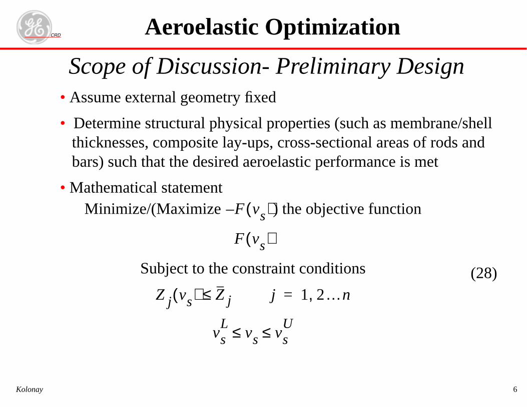
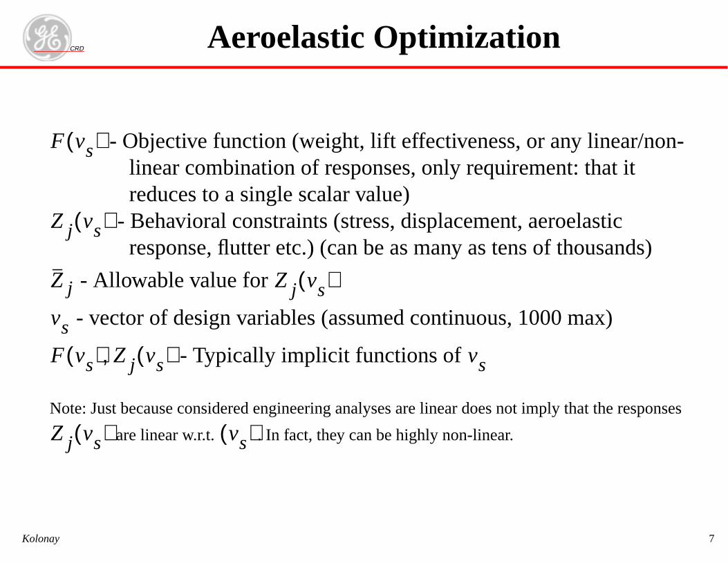
RDScope of Discussion- Prelimin• Assume external geometry fixed
• Determine structural physical properties (suthicknesses, composite lay-ups, cross-sectibars) such that the desired aeroelastic perfo
• Mathematical statementMinimize/(Maximize F– vs( )) the objective f
F vs( )
Subject to the constraint condition
Z j vs( ) Z j≤ j 1 2…n,=
vsL
vs vsU≤ ≤
Aeroelastic Optimizatio
CKolonay
7
s, or any linear/non-uirement: that it
ent, aeroelastics tens of thousands)
us, 1000 max)
oes not imply that the responses
ar.
on
RD- Objective function (weight, lift effectiveneslinear combination of responses, only reqreduces to a single scalar value)
- Behavioral constraints (stress, displacemresponse, flutter etc.) (can be as many a
- Allowable value for
- vector of design variables (assumed continuo
- Typically implicit functions of
e: Just because considered engineering analyses are linear d
are linear w.r.t. . In fact, they can be highly non-line
vs)
vs( )
Z j vs( )
vs) Z j vs( ), vs
vs( ) vs( )
Aeroelastic Optimizati
CKolonay
Not
F(
Z j
Z j
vs
F(
Z j
8
athematical program-algorithms along with;
detailed Engi-)
on
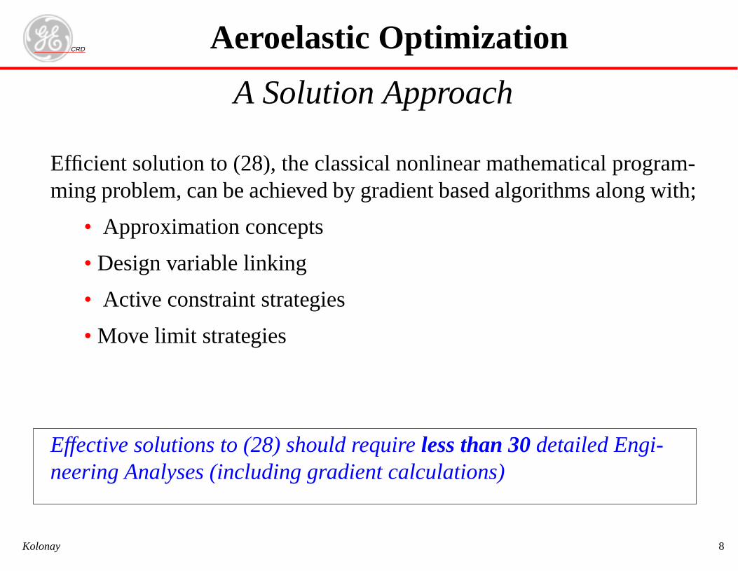
RDA Solution Approach
cient solution to (28), the classical nonlinear mng problem, can be achieved by gradient based
• Approximation concepts
• Design variable linking
• Active constraint strategies
• Move limit strategies
ective solutions to (28) should requireless than 30ering Analyses (including gradient calculations
Aeroelastic Optimizati
CKolonay
Effimi
Effne
9
ts
s only gradients)
n matrix (difficult tos available.
vi
fvi voi–( )
vi
fxi xoi–( )
xoi2
---------------------------
on
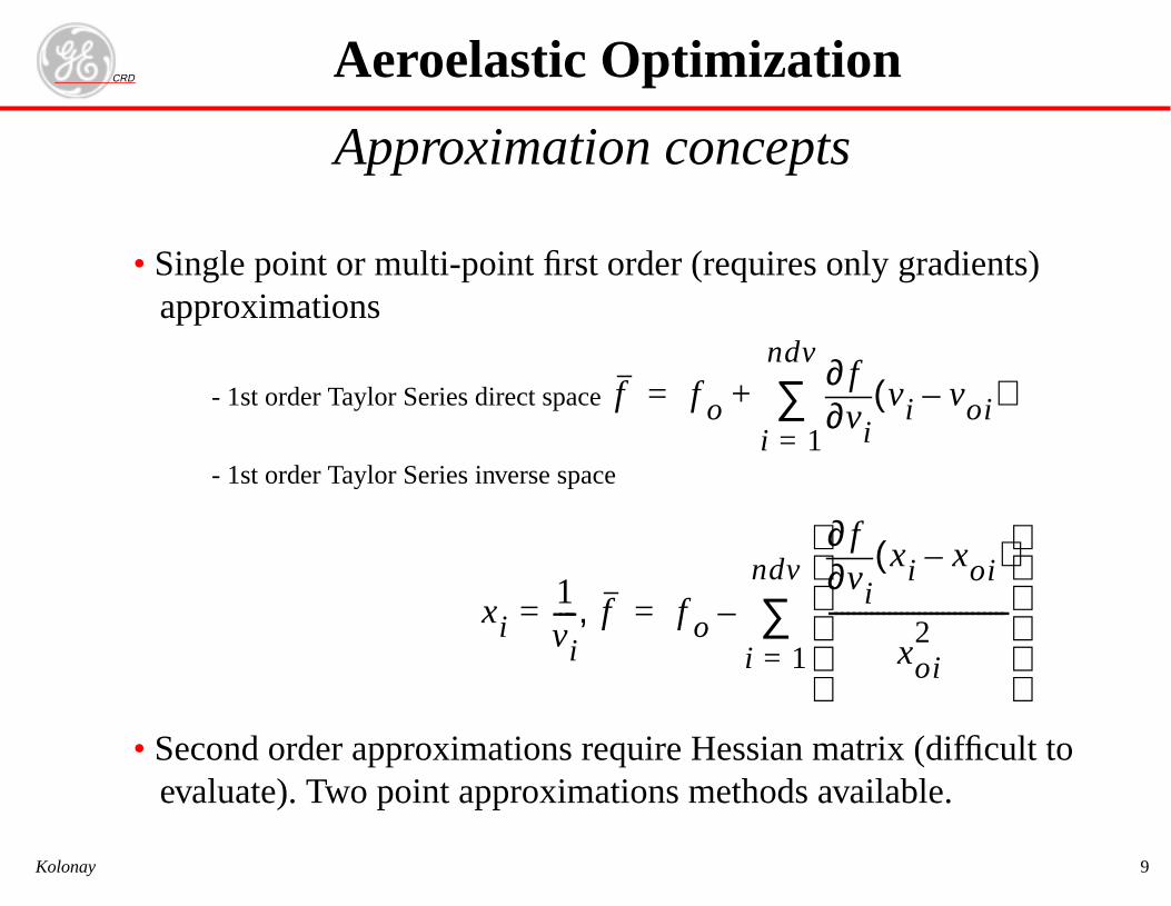
RDApproximation concep
• Single point or multi-point first order (requireapproximations
- 1st order Taylor Series direct space
- 1st order Taylor Series inverse space
• Second order approximations require Hessiaevaluate). Two point approximations method
f f o ∂∂
i 1=
ndv
∑+=
xi1vi----= f, f o
∂∂
---
i 1=
ndv
∑–=
Aeroelastic Optimizati
CKolonay
CRD
Kolonay 10
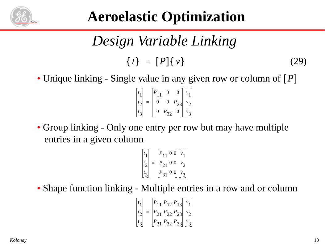
Design Variable Linking(29)
• Unique linking - Single value in any given row or column of
• Group linking - Only one entry per row but may have multipleentries in a given column
• Shape function linking - Multiple entries in a row and or column
t{ } P[ ] v{ }=
P[ ]t1
t2
t3
P11 0 0
0 0 P23
0 P32 0
v1
v2
v3
=
t1
t2
t3
P11 0 0
P21 0 0
P31 0 0
v1
v2
v3
=
t1
t2
t3
P11 P12 P13
P21 P22 P23
P31 P32 P33
v1
v2
v3
=
Aeroelastic Optimization
CRD
Kolonay 11
Active constraint strategies
• Pass an “active” subset of the constraints to the approximate prob-lem
- Retain all violated constraints- Retain constraints within 10% of the boundary- Don’t retain more than 1 or 2 times NDV unless necessary
• Update the “active” set for each new approximate problem
• Calculate gradients for only the “active” set of constraints- Results in large computational savings
Aeroelastic Optimization
CRD
Kolonay 12
Move Limit Strategies• Using approximations for constraints functions, objective function,
constraint function gradients, and objective function gradientsmust be recognized by imposing constraints on the movement ofthe design variables for any given approximate problem.
• movlim is problem dependent, values typically can range anywherefrom 1.1 to 2.0
voimovlim------------------ vi movlim voi×≤ ≤
Aeroelastic Optimization
CRD
Kolonay 13
Gradient Calculations
• Efficient accurate gradient calculations areessentialto gradientbased solutions to (28).
• If at all possible avoid finite difference gradients- Costly, and prone to step size problems
• Use analytic or semi-analytic gradients
Aeroelastic Optimization
RD
14
• lastic gradientselemental level.
•
(30)
ixede )
r)
ar bnonlinearee, )
r
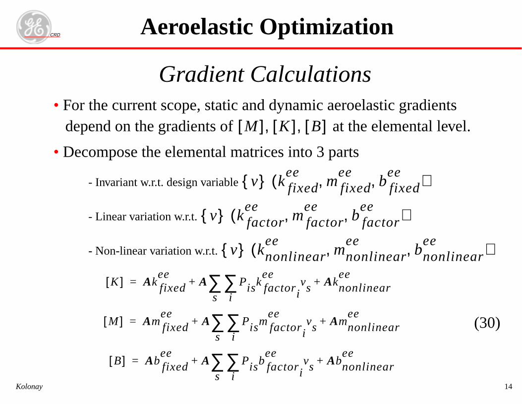
Gradient CalculationsFor the current scope, static and dynamic aeroedepend on the gradients of at the
Decompose the elemental matrices into 3 parts
- Invariant w.r.t. design variable
- Linear variation w.r.t.
- Non-linear variation w.r.t.
M[ ] K[ ] B[ ], ,
v{ } k fixedee
mfixedee
bfe, ,(
v{ } k factoree
mfactoree
bfactoee, ,(
v{ } knonlinearee
mnonlineee,(
K[ ] Ak fixedee
A Pisk factori
eevs
i∑
s∑ Aknonlinear
ee+ +=
M[ ] Amfixedee
A Pismfactori
eevs
i∑
s∑ Amnonlinea
ee+ +=
B[ ] Ab fixedee
A Pisb factori
eevs
i∑
s∑ Abnonlinear
ee+ +=
Aeroelastic Optimization
CKolonay
RD
15
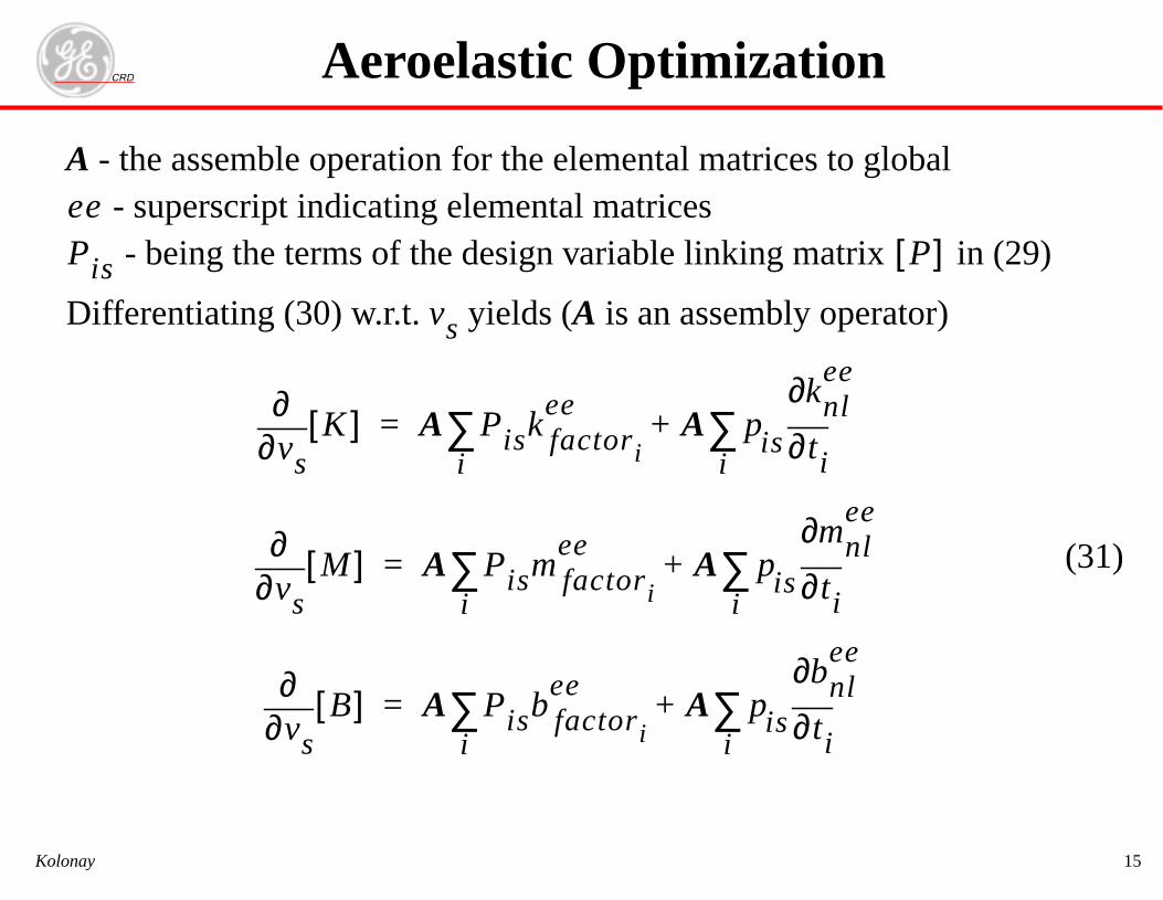
th es to global - atrix in (29)
e perator)
(31)
P[ ]
le
n
e assemble operation for the elemental matricsuperscript indicating elemental matrices being the terms of the design variable linking m
rentiating (30) w.r.t. yields (A is an assembly ovs
vs∂∂
K[ ] A Pisk factori
ee
i∑ A pis ti∂
∂knlee
i∑+=
vs∂∂
M[ ] A Pismfactori
ee
i∑ A pis ti∂
∂mne
i∑+=
vs∂∂
B[ ] A Pisbfactori
ee
i∑ A pis ti∂
∂bnlee
i∑+=
Aeroelastic Optimizatio
CKolonay
A - -
Diff
eePis
16
rward finite dif-
(32)
i-analytic∇
on
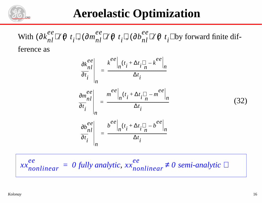
RDth by fo
ence as
fully analytic, sem
∂knlee( ) ∂ti( )⁄ ∂mnl
ee( ) ∂ti( )⁄ ∂bnlee( ) ∂ti( )⁄, ,
ti∂
∂knlee
n
kee
nti ∆ti+( )
nkee
n–
∆ti-----------------------------------------------------------=
ti∂
∂mnlee
n
mee
nti ∆ti+( )
nm
een
–
∆ti--------------------------------------------------------------=
ti∂
∂bnlee
n
bee
nti ∆ti+( )
nbee
n–
∆ti------------------------------------------------------------=
nonlinearee
0= xxnonlinearee
0≠
Aeroelastic Optimizati
CKolonay
Wi
fer
xx
CRD
Kolonay 17
Aeroelastic Constraints Considered
• Static Aeroelastic Constraints- Stress- Strain- Displacement- Flexible stability derivatives (lift effectiveness, control surface effectiveness, etc.)- Aileron effectiveness- Free trim parameter constraints
• Dynamic Aeroelastic Constraints- Flutter
Aeroelastic Optimization
CR
D
Ko
lon
ay
18
Aeroelastic O
ptimization
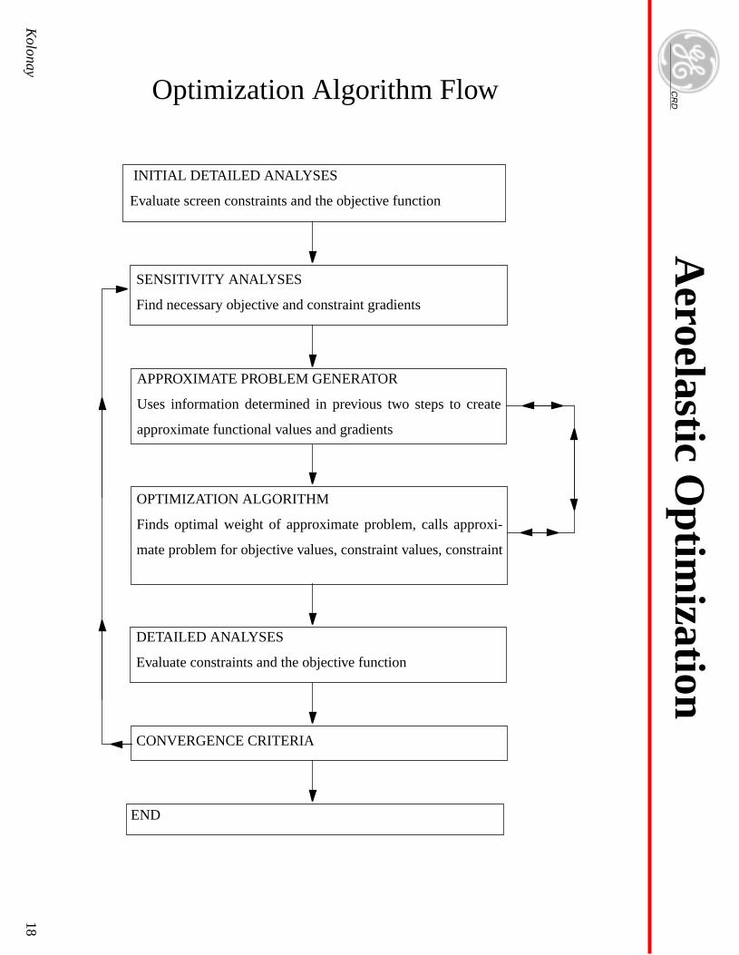
INITIAL DETAILED ANALYSES
Evaluate screen constraints and the objective function
SENSITIVITY ANALYSES
Find necessary objective and constraint gradients
APPROXIMATE PROBLEM GENERATOR
Uses information determined in previous two steps to create
approximate functional values and gradients
END
DETAILED ANALYSES
Evaluate constraints and the objective function
OPTIMIZATION ALGORITHM
Finds optimal weight of approximate problem, calls approxi-
mate problem for objective values, constraint values, constraint
CONVERGENCE CRITERIA
Optimization Algorithm Flow
CRD
Kolonay 19
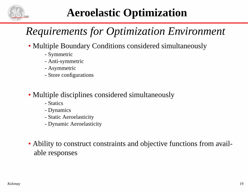
Requirements for Optimization Environment• Multiple Boundary Conditions considered simultaneously
- Symmetric- Anti-symmetric- Asymmetric- Store configurations
• Multiple disciplines considered simultaneously- Statics- Dynamics- Static Aeroelasticity- Dynamic Aeroelasticity
• Ability to construct constraints and objective functions from avail-able responses
Aeroelastic Optimization
CRD
Kolonay 20
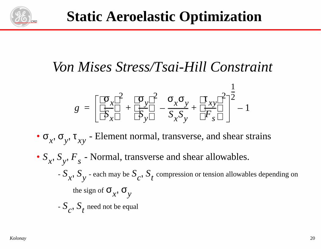
Von Mises Stress/Tsai-Hill Constraint
• - Element normal, transverse, and shear strains
• - Normal, transverse and shear allowables.
- - each may be compression or tension allowables depending on
the sign of
- need not be equal
gσxSx------
2 σy
Sy------
2 σxσy
SxSy-------------–
τxyFs-------
2
+ +
12---
1–=
σx σy τxy, ,
Sx Sy Fs, ,
Sx Sy, Sc St,
σx σy,
Sc St,
Static Aeroelastic Optimization
CRD
Kolonay 21
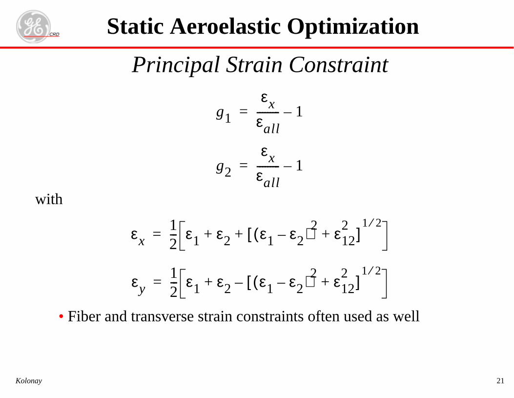
Principal Strain Constraint
with
• Fiber and transverse strain constraints often used as well
g1
εxεall--------- 1–=
g2
εxεall--------- 1–=
εx12--- ε1 ε2 ε1 ε2–( )2 ε12
2+[ ]
1 2⁄+ +=
εy12--- ε1 ε2 ε1 ε2–( )2 ε12
2+[ ]
1 2⁄–+=
Static Aeroelastic Optimization
CRD
Kolonay 22
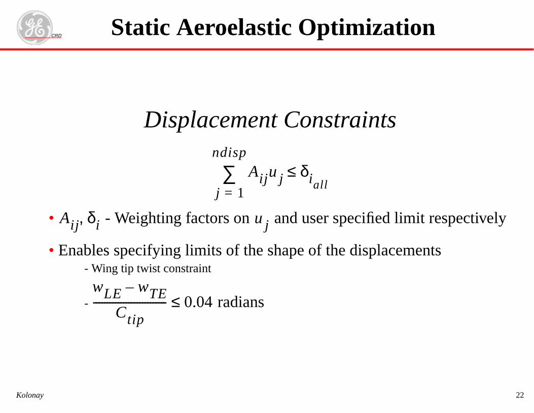
Displacement Constraints
• - Weighting factors on and user specified limit respectively
• Enables specifying limits of the shape of the displacements- Wing tip twist constraint
-
Aij ujj 1=
ndisp
∑ δiall≤
Aij δi, uj
wLE wTE–
Ctip--------------------------- 0.04 radians≤
Static Aeroelastic Optimization

CRD
Kolonay 23
Aileron Effectiveness Constraint
With
- Rolling moment about the aircraft centerline
- Aileron deflection
- Roll rate nondimensionalized by wing span and aircraft velocity
- Flexibility effects are included in the derivatives
• Steady roll rate achievable for a unit value of aileron deflection.
εmin εeff εmax≤ ≤
εeff
Clδa f
Cl pb2V-------
f--------------------–=
Cl
δa
pb2V-------
f
Static Aeroelastic Optimization
CRD
Kolonay 24
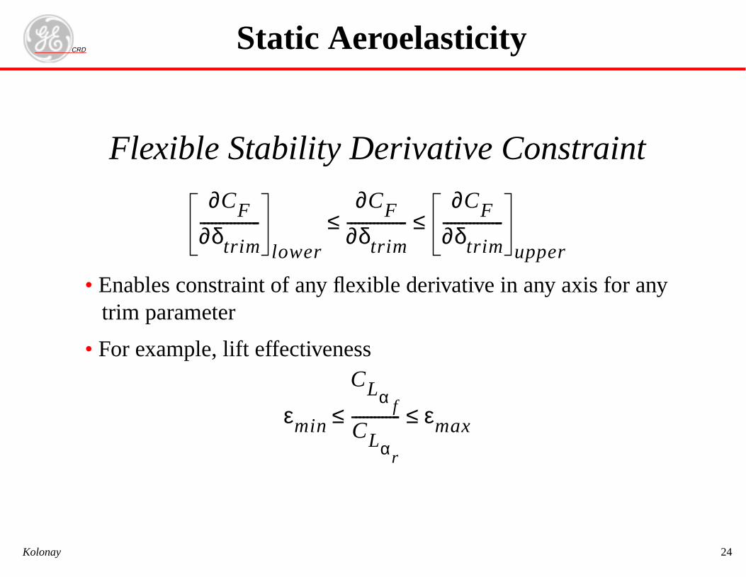
Flexible Stability Derivative Constraint
• Enables constraint of any flexible derivative in any axis for anytrim parameter
• For example, lift effectiveness
∂CF∂δtrim----------------
lower
∂CF∂δtrim----------------
∂CF∂δtrim----------------
upper
≤ ≤
εmin
CLα f
CLαr
------------- εmax≤ ≤
Static Aeroelasticity
CRD
Kolonay 25
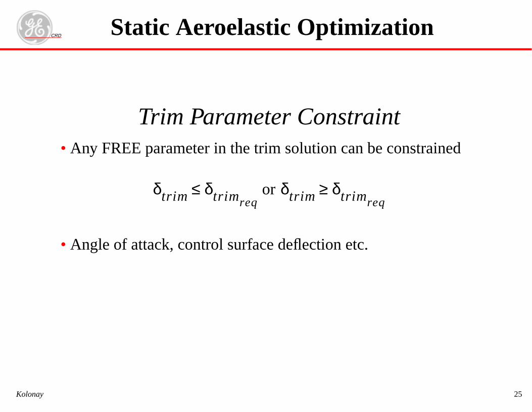
Trim Parameter Constraint• Any FREE parameter in the trim solution can be constrained
• Angle of attack, control surface deflection etc.
δtrim δtrimreq≤ or δtrim δtrimreq
≥
Static Aeroelastic Optimization
CRD
Kolonay 26
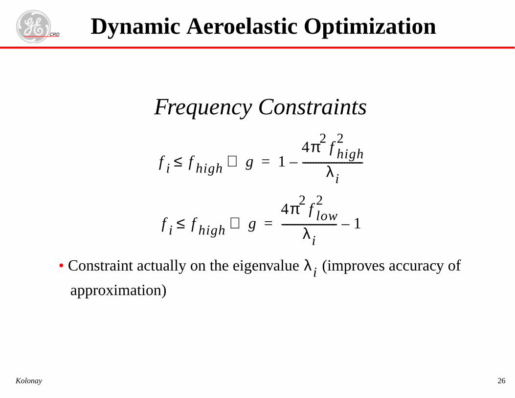
Frequency Constraints
• Constraint actually on the eigenvalue (improves accuracy of
approximation)
f i f high≤ g⇒ 14π2
f high2
λi-----------------------–=
f i f high≤ g⇒4π2
f low2
λi--------------------- 1–=
λi
Dynamic Aeroelastic Optimization
CRD
Kolonay 27
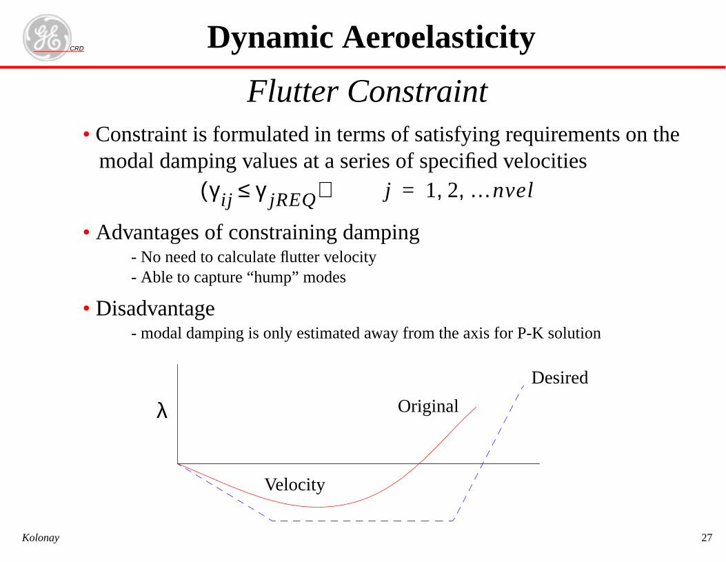
Flutter Constraint• Constraint is formulated in terms of satisfying requirements on the
modal damping values at a series of specified velocities
• Advantages of constraining damping- No need to calculate flutter velocity- Able to capture “hump” modes
• Disadvantage- modal damping is only estimated away from the axis for P-K solution
γ ij γ jREQ≤( ) j 1 2 …nvel, ,=
Dynamic Aeroelasticity
Velocity
Original
Desired
λ
CRD
Kolonay 28
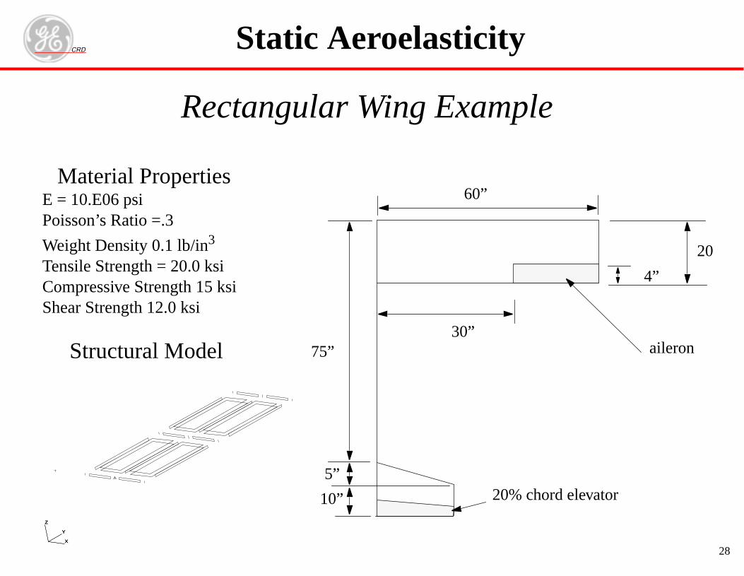
Rectangular Wing Example
X
Y
Z
X
Y
Z
Static Aeroelasticity
Material PropertiesE = 10.E06 psiPoisson’s Ratio =.3
Weight Density 0.1 lb/in3
Tensile Strength = 20.0 ksiCompressive Strength 15 ksiShear Strength 12.0 ksi
4”
60”
30”
20
75”
5”
10” 20% chord elevator
aileronStructural Model
CRD
Kolonay 29
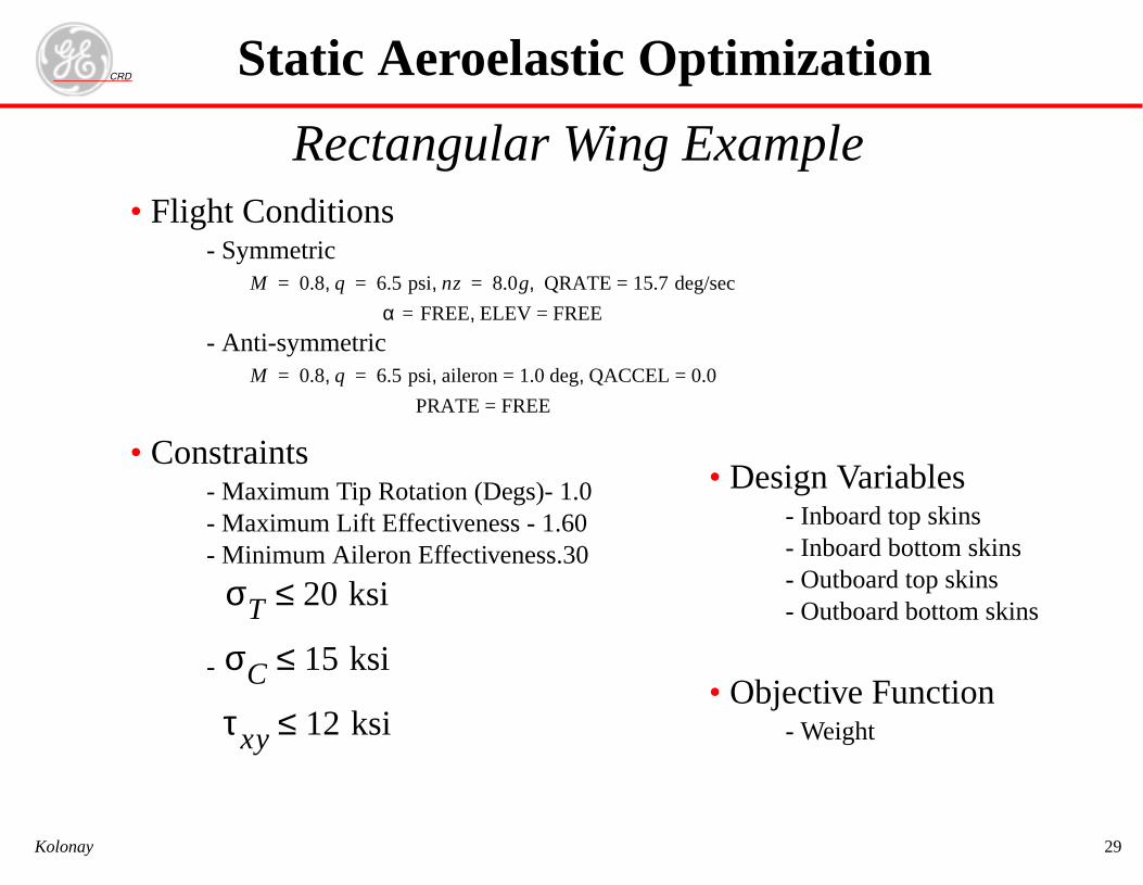
Rectangular Wing Example• Flight Conditions
- Symmetric
- Anti-symmetric
• Constraints- Maximum Tip Rotation (Degs)- 1.0- Maximum Lift Effectiveness - 1.60- Minimum Aileron Effectiveness.30
-
M 0.8 q, 6.5 psi nz, 8.0g QRATE = 15.7 deg/sec,= = =
α FREE= ELEV = FREE,
M 0.8 q, 6.5 psi aileron = 1.0 deg QACCEL = 0.0, ,= =
PRATE = FREE
σT 20 ksi≤
σC 15 ksi≤
τxy 12 ksi≤
Static Aeroelastic Optimization
• Design Variables- Inboard top skins- Inboard bottom skins- Outboard top skins- Outboard bottom skins
• Objective Function- Weight
CRD
Kolonay 30
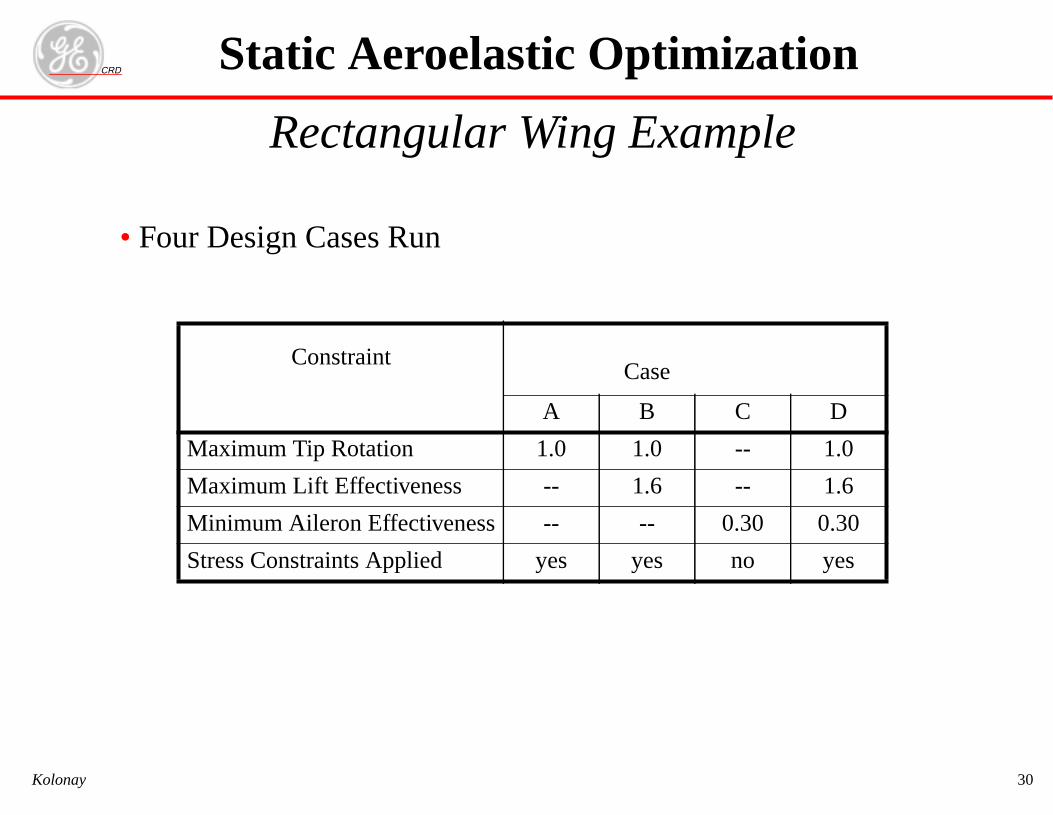
Rectangular Wing Example
• Four Design Cases Run
ConstraintCase
A B C D
Maximum Tip Rotation 1.0 1.0 -- 1.0
Maximum Lift Effectiveness -- 1.6 -- 1.6
Minimum Aileron Effectiveness -- -- 0.30 0.30
Stress Constraints Applied yes yes no yes
Static Aeroelastic Optimization
CRD
Kolonay 31
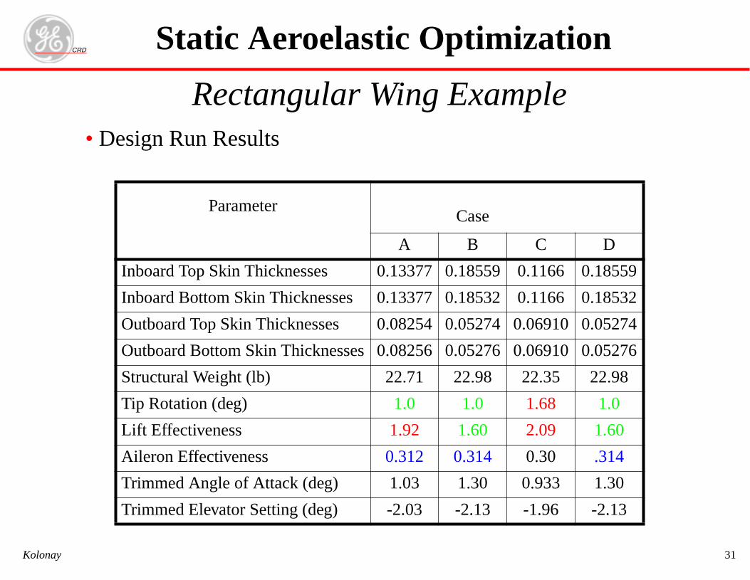
Rectangular Wing Example• Design Run Results
ParameterCase
A B C D
Inboard Top Skin Thicknesses 0.13377 0.18559 0.1166 0.18559
Inboard Bottom Skin Thicknesses 0.13377 0.18532 0.1166 0.18532
Outboard Top Skin Thicknesses 0.08254 0.05274 0.06910 0.05274
Outboard Bottom Skin Thicknesses 0.08256 0.05276 0.06910 0.05276
Structural Weight (lb) 22.71 22.98 22.35 22.98
Tip Rotation (deg) 1.0 1.0 1.68 1.0
Lift Effectiveness 1.92 1.60 2.09 1.60
Aileron Effectiveness 0.312 0.314 0.30 .314
Trimmed Angle of Attack (deg) 1.03 1.30 0.933 1.30
Trimmed Elevator Setting (deg) -2.03 -2.13 -1.96 -2.13
Static Aeroelastic Optimization
CRD
Kolonay 32
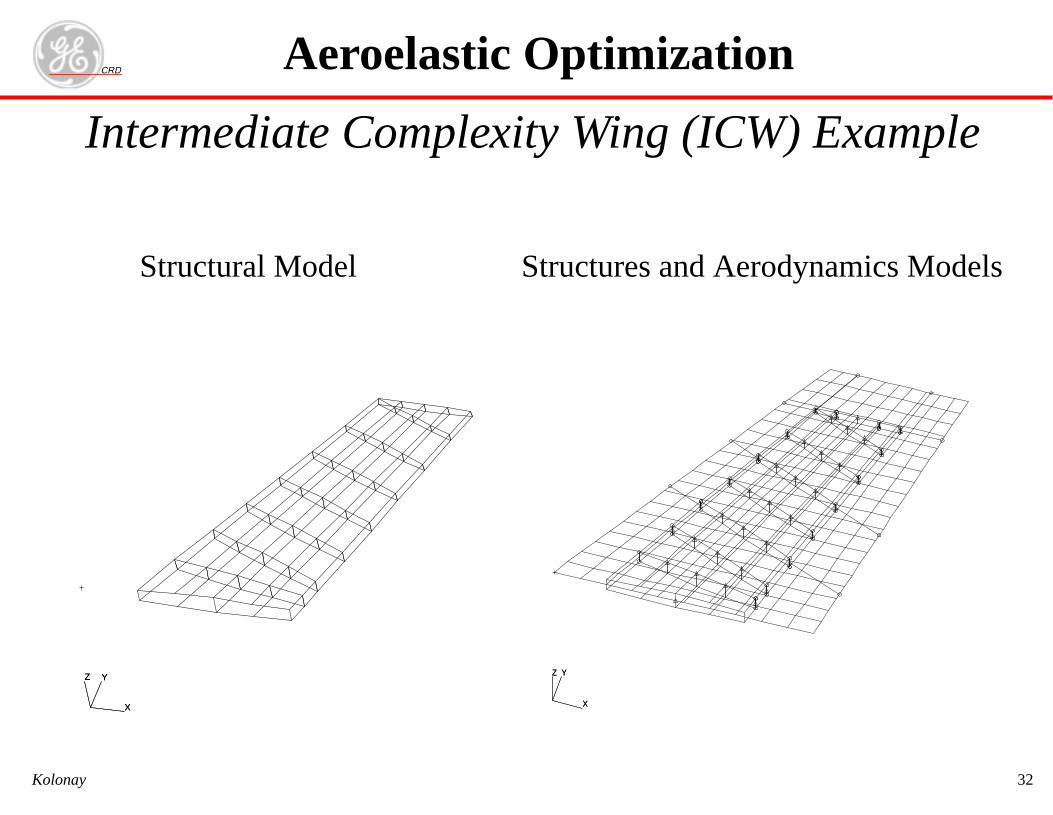
Intermediate Complexity Wing (ICW) Example
Aeroelastic Optimization
X
YZ
X
YZ
X
YZ
X
YZ
Structural Model Structures and Aerodynamics Models
CRD
Kolonay 33
Aeroelastic Optimization
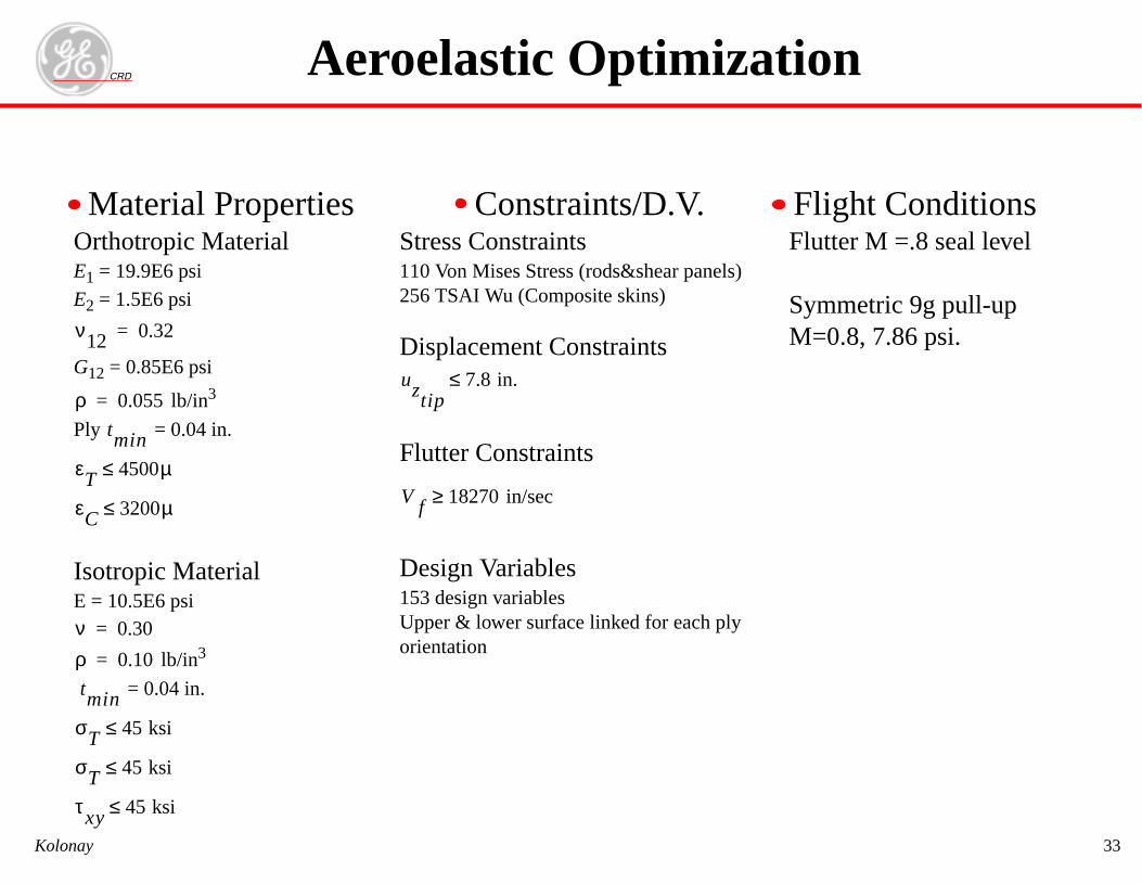
Orthotropic MaterialE1 = 19.9E6 psi
E2 = 1.5E6 psi
G12 = 0.85E6 psi
lb/in3
Ply = 0.04 in.
Isotropic MaterialE = 10.5E6 psi
lb/in3
= 0.04 in.
ν12 0.32=
ρ 0.055=
tmin
εT 4500µ≤
εC 3200µ≤
ν 0.30=
ρ 0.10=
tmin
σT 45 ksi≤
σT 45 ksi≤
τxy 45 ksi≤
Stress Constraints110 Von Mises Stress (rods&shear panels)256 TSAI Wu (Composite skins)
Displacement Constraints
Flutter Constraints
Design Variables153 design variablesUpper & lower surface linked for each plyorientation
uztip7.8 in.≤
V f 18270 in/sec≥
Material Properties Constraints/D.V.Flutter M =.8 seal level
Symmetric 9g pull-upM=0.8, 7.86 psi.
Flight Conditions
CRD
Kolonay 34
2 4 6 8 10 12
3680
3700
3720
3740
3760
3780
3800
3820
3840
Aeroelastic Optimization
Iteration
Wei
ght (
lbs)
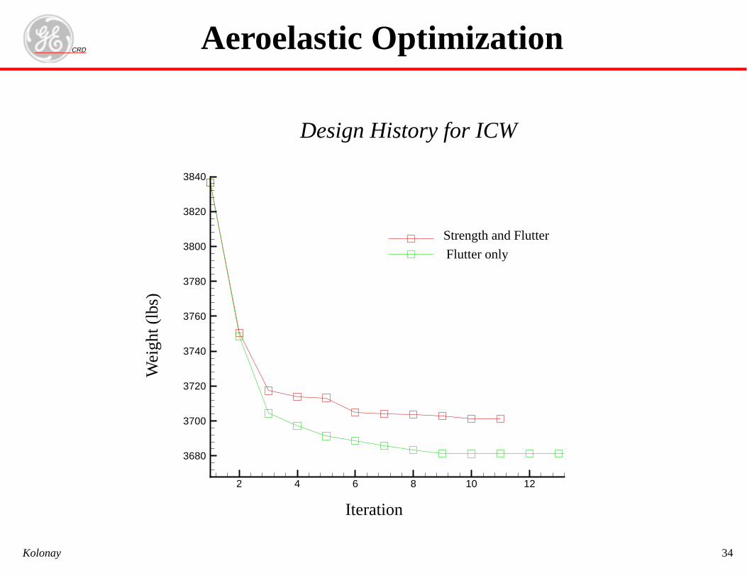
Design History for ICW
Flutter only
Strength and Flutter
CRD
Kolonay 35
14000 16000 18000 20000-0.9
-0.8
-0.7
-0.6
-0.5
-0.4
-0.3
-0.2
-0.1
0
0.1
Mode 1Mode 2Mode 3Mode 4Mode 5Mode 6
Aeroelastic Optimization
Velocity (in/sec)
Dam
ping
Rat
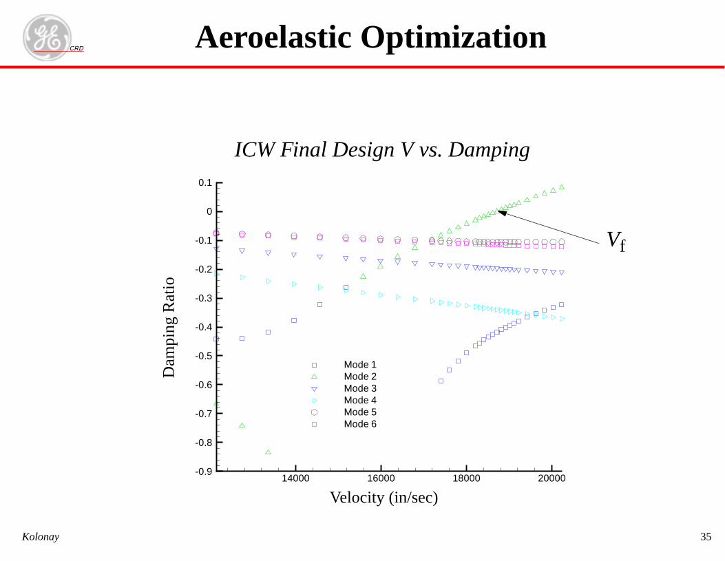
ioICW Final Design V vs. Damping
Vf
CRD
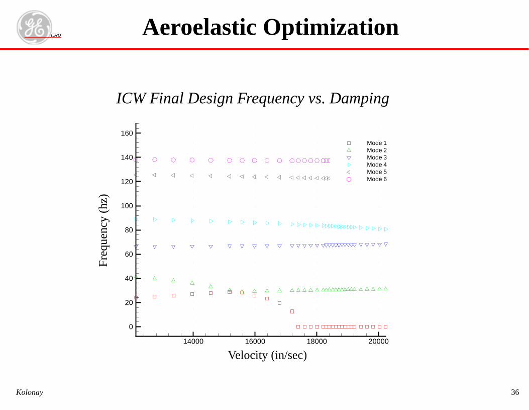
Kolonay 36
Aeroelastic Optimization
14000 16000 18000 20000
0
20
40
60
80
100
120
140
160Mode 1Mode 2Mode 3Mode 4Mode 5Mode 6
Velocity (in/sec)
ICW Final Design Frequency vs. DampingF
requ
ency
(hz
)
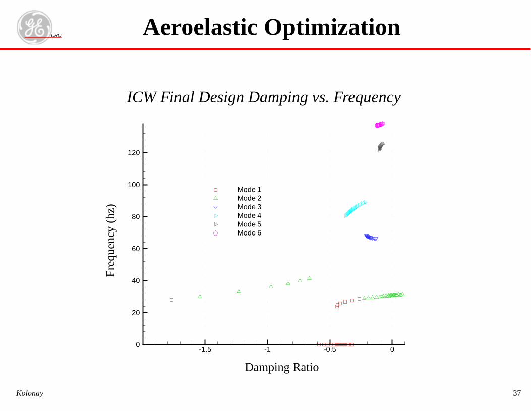
CRD
Kolonay 37
-1.5 -1 -0.5 00
20
40
60
80
100
120
Mode 1Mode 2Mode 3Mode 4Mode 5Mode 6
Aeroelastic Optimization
Damping Ratio
Fre
quen
cy (
hz)
ICW Final Design Damping vs. Frequency
CRD
Kolonay 38
Trim Optimization• Number of FREE aerodynamic parameters > Number of trim DOF
• Allows redundant control surfaces
• Objective function based on trim parameters/trim DOF and calcu-lated responses (integrated maneuver loads, hinge moments etc.)
• Constraints based on trim parameters/trim DOF (integrated maneu-ver loads, hinge moments etc.)
Aeroelastic Optimization
CRD
Kolonay 39
Trim Optimization Problem• Problem is formulated as nonlinear mathematical programming problem
• With a vector of control effectors (control surfaces, thrust, user
defined controllers, smart structures)
• Design constraints and objectives are control effector limits, integratedmaneuver loads, and maneuver performance (e.g. roll rate)
• The procedure uses the redundant control effectors and trim parameters( etc.)to drive the trim state to a constrained minimum for the objec-tive and constraints defined
Minimize/(Maximize F– vs( )) the objective function
F vs( )
Subject to the constraint conditions
gj vs( ) 0≤ j 1 2…ncon,=
vsL
vs vsU
≤ ≤
vs
α β,
Aeroelastic Optimization
CRD
Kolonay 40
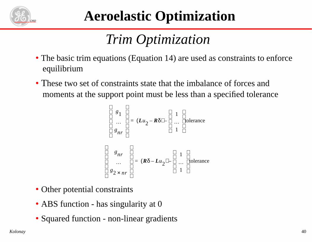
Trim Optimization• The basic trim equations (Equation 14) are used as constraints to enforce
equilibrium
• These two set of constraints state that the imbalance of forces andmoments at the support point must be less than a specified tolerance
• Other potential constraints
• ABS function - has singularity at 0
• Squared function - non-linear gradients
g1
…gnr
Lu2 Rδ–( )1
…1
tolerance–=
gnr
…g2 nr×
Rδ Lu2–( )1
…1
tolerance–=
Aeroelastic Optimization
CRD
Kolonay 41
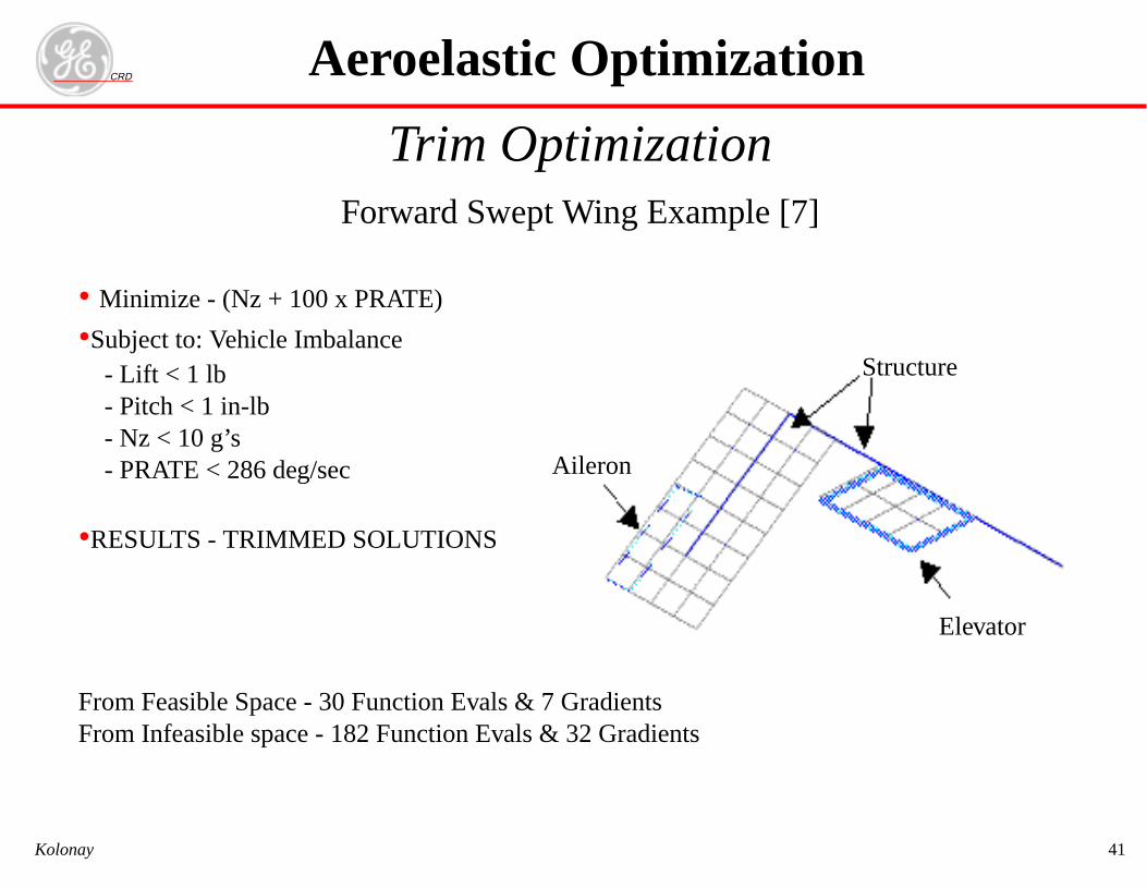
Trim OptimizationForward Swept Wing Example [7]
• Minimize - (Nz + 100 x PRATE)
•Subject to: Vehicle Imbalance - Lift < 1 lb - Pitch < 1 in-lb - Nz < 10 g’s - PRATE < 286 deg/sec
•RESULTS - TRIMMED SOLUTIONS
From Feasible Space - 30 Function Evals & 7 GradientsFrom Infeasible space - 182 Function Evals & 32 Gradients
Aeroelastic Optimization
Structure
Elevator
Aileron
CRD
Kolonay 42
Global Aeroelastic Design Software• MSC/NASTRAN (U.S.)
• UAI/ASTROS (recently bought by MSC) (U.S.)
• ELFINI (France, Dessault)
• LAGRANGE (Germany, formerly MBB)
• STARS (Great Britain, RAE)
• OPTSYS (Sweden, SAAB)
• COMPASS (China)
• ARGON (Russia, Central Aerohydrodynamic Institute)
Aeroelastic Optimization Software
43
nonlinear combinations)
ftware
RDMSC/NASTRAN• General Modeling/Analysis Environment
- Multiple boundary conditions- Multiple disciplines per boundary condition- Selectable aerodynamic models- Optimization solvers (MMFD, SLP, SQP)
• Design variables- Element properties, shape- Design variable linking (physical, group, shape)
• Objective Functions- User definable based on available responses (linear/
• Static Aeroelastic Constraints•Stress•Strain•Displacement•Buckling (Panel, Euler column)
Aeroelastic Optimization So
CKolonay
44
trol surface effectiveness,
constraints
fective surfaces
lity in PATRAN environment
oftware
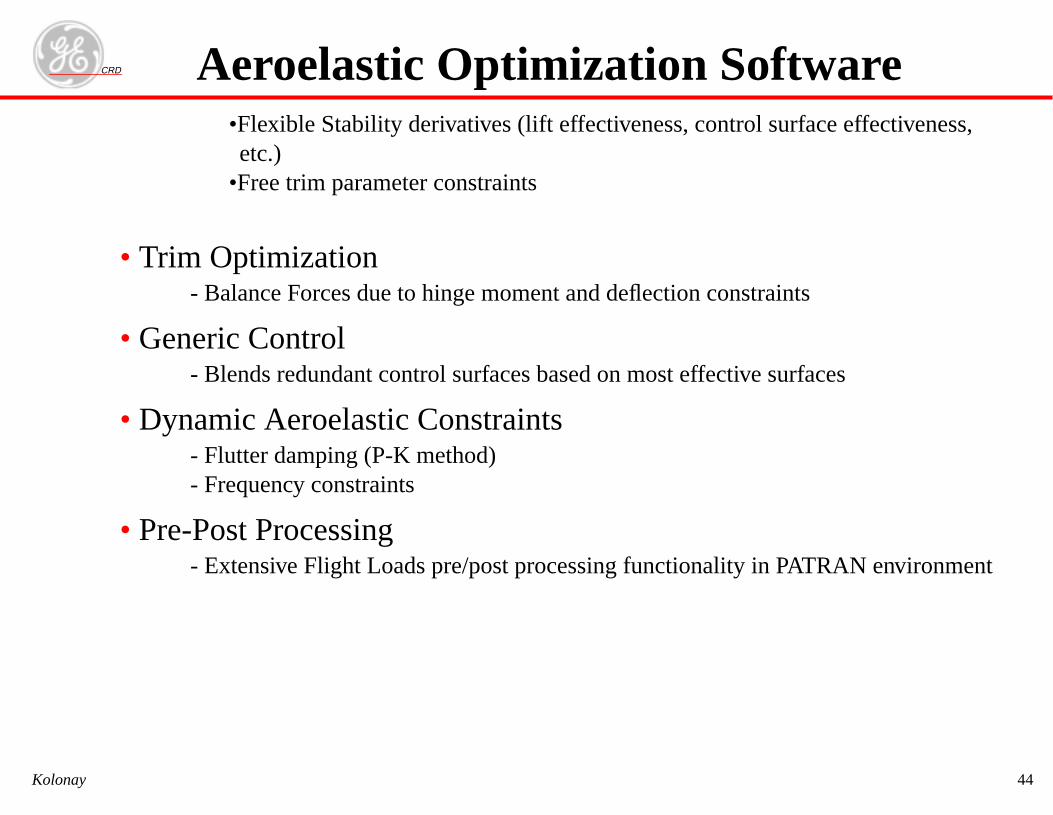
RD•Flexible Stability derivatives (lift effectiveness, conetc.)
•Free trim parameter constraints
• Trim Optimization- Balance Forces due to hinge moment and deflection
• Generic Control- Blends redundant control surfaces based on most ef
• Dynamic Aeroelastic Constraints- Flutter damping (P-K method)- Frequency constraints
• Pre-Post Processing- Extensive Flight Loads pre/post processing functiona
Aeroelastic Optimization S
CKolonay
45
pabilities
nonlinear combinations)
nonlinear combinations)
ftware
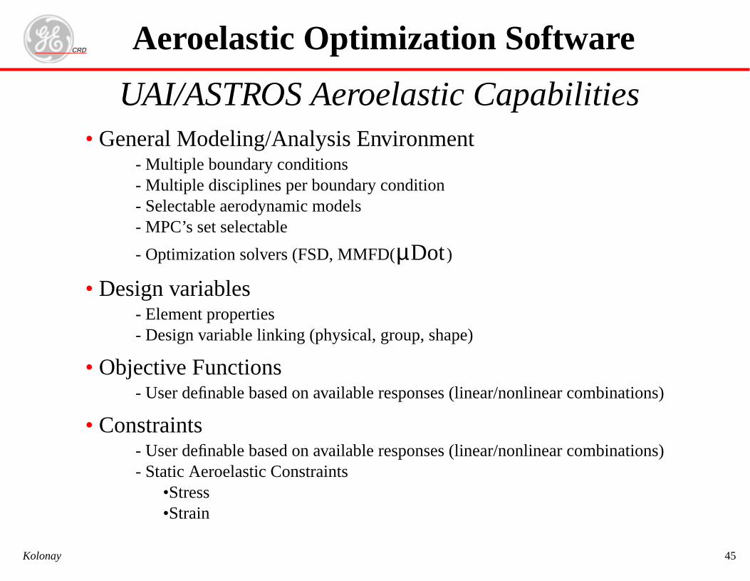
RDUAI/ASTROS Aeroelastic Ca• General Modeling/Analysis Environment
- Multiple boundary conditions- Multiple disciplines per boundary condition- Selectable aerodynamic models- MPC’s set selectable
- Optimization solvers (FSD, MMFD( )
• Design variables- Element properties- Design variable linking (physical, group, shape)
• Objective Functions- User definable based on available responses (linear/
• Constraints- User definable based on available responses (linear/- Static Aeroelastic Constraints
•Stress•Strain
µDot
Aeroelastic Optimization So
CKolonay
46
trol surface effectiveness,
F and calculated responses
rated maneuver loads, hinge
d on available setdule converges
oftware
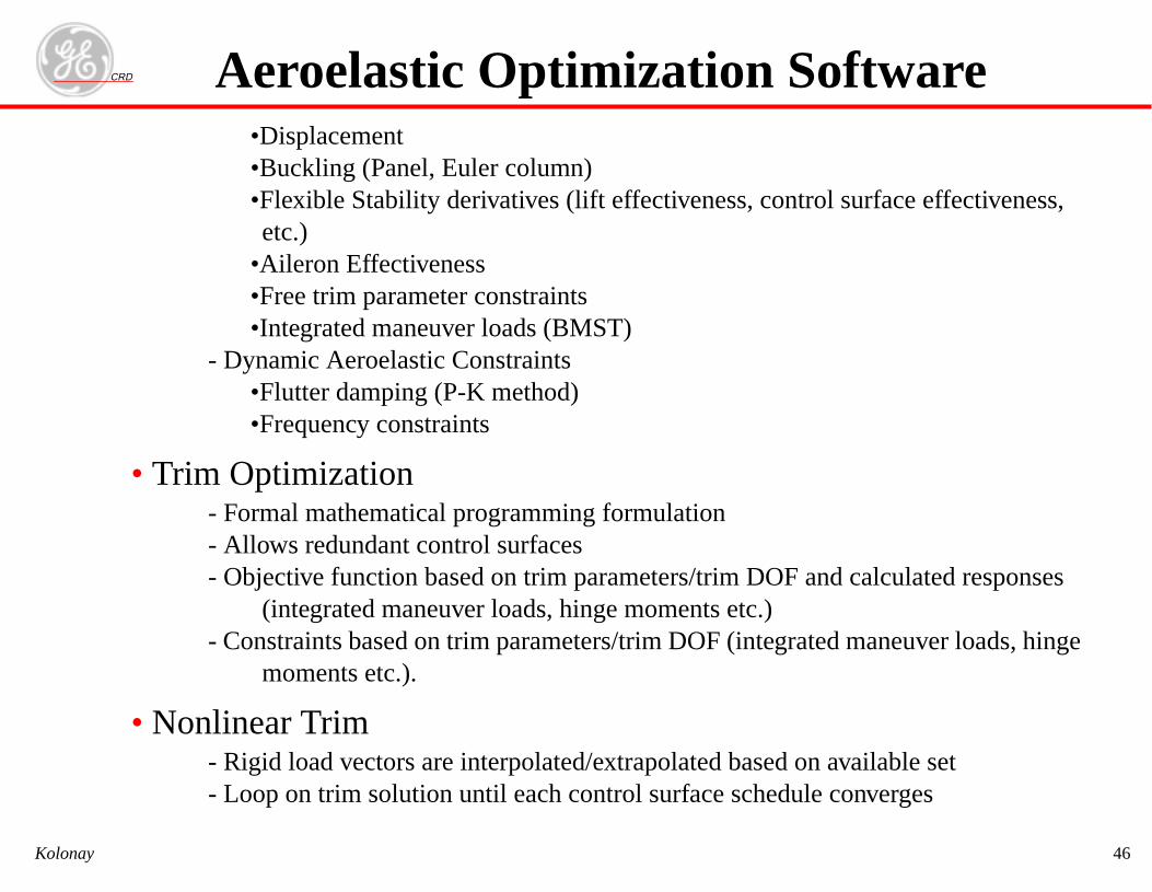
RD•Displacement•Buckling (Panel, Euler column)•Flexible Stability derivatives (lift effectiveness, conetc.)
•Aileron Effectiveness•Free trim parameter constraints•Integrated maneuver loads (BMST)
- Dynamic Aeroelastic Constraints•Flutter damping (P-K method)•Frequency constraints
• Trim Optimization- Formal mathematical programming formulation- Allows redundant control surfaces- Objective function based on trim parameters/trim DO
(integrated maneuver loads, hinge moments etc.)- Constraints based on trim parameters/trim DOF (integ
moments etc.).
• Nonlinear Trim- Rigid load vectors are interpolated/extrapolated base- Loop on trim solution until each control surface sche
Aeroelastic Optimization S
CKolonay
CRD
Kolonay 47
• Very easy to add user defined functionality and tailor the system
• Pre-Post Processing- Bulk data input 90% compatible with NASTRAN- Database accessible with SQL type interface and API
Aeroelastic Optimization Software
CRD
Kolonay 48
1. Neill, D.J., Herendeen, D.L., Venkayya, V.B., “ASTROS Enhancements, Vol III- ASTROSTheoretical Manual”, WL-TR-95-3006.
2. Neill, D. J., Johnson E. H., Herendeen K. L., “Automated structural Optimization System(ASTROS),” AFWAL-TR-883028 Volume II-User’s Manual, April 1988.
3. Hajela, P. “A Root Locus Based Flutter Synthesis Procedure,” AIAA Paper 83-0063, Jan.1983.
4. Grumman Aerospace Corporation, “An Automated Procedure for Flutter and Strength Analy-sis and Optimization of Aerospace Vehicles Volume I. Theory and Application,”, AFFDL-TR-75-137,.
5. Hassig, H.J., “An Approximate True Damping Solution of the Flutter Equation by Determi-nant Iteration,” Journal of Aircraft, Vol. 8, No. 11, November 1971, pp. 885-889.
6. Neill, D.J., “MSC/Flight Loads and Dynamics Training,”, The MacNeal-Schwendler Corpora-tion, 815 Colorado Boulevard, Los Angeles, CA, August 1999.
7. Love, M.L., Egle, D.D., “Aerodynamic Analysis for the Design Environment (AANDE), The-oretical and Applications Studies Document,” Lockheed Martin Tactical Aircraft Systems Codeident: 81755.
References


![Level-Set Topology Optimization with Aeroelastic Constraints · Level-Set Topology Optimization with Aeroelastic Constraints ... 13]. 1 Research Associate, p.d ... Methods are presented](https://img.pdfslide.net/doc/110x75/5b8a9dd97f8b9a50388cadce/level-set-topology-optimization-with-aeroelastic-constraints-level-set-topology.jpg)