Embed Size (px)
Citation preview
International Journal of Thesis Projects and Dissertations (IJTPD) Vol. 2, Issue 2, PP: (47-57), Month: April - June 2014, Available At: www.researchpublish.com
Page | 47 Research Publish Journals
Static Analysis and Geometric Optimization of
Independent Suspension Link
Vijaykumar V Solanki1, Prof. N.S.Patel
2
1PG Student,
2Professor
1,2Department of Mechanical Engineering, Government Engineering Collage, Dahod, Gujarat, India
Abstract: As the lower arm of suspension takes up all dynamic loads on it leads to fatigue failure of arm and it
hampered the whole suspension and more prone to harm human also. This paper consider the von-misses stress
analysis of present suspension link carried out for static deflection and von-misses stress contour plot are plotted.
The result shows that maximum deflection range is 0mm to 8.22mm. And von-misses stress shows minimum value
of 0.86Mpa and Maximum is 3752Mpa. As the max von-misses are above the yield point of material some
corrective action is to be done at the point where the link is connected to the chassis. After observing the stresses
produced on arm it is found that some metal thickness should be increases at the chassis connection point to avoid
the failure. So the U shape bracket is implemented their and CP element is used to again define the connectivity
between the previous model and new bracket. After change in design the Minimum value of deformation range
from 0.00 mm to maximum value of deformation is 1.925 mm. and the maximum stress developed is 736.888 Mpa.
And maximum stress shown at only stress concentration area. Means change in design increases load capacity of
arm in dynamic condition and as stress and deflection decreases so frequency also improved. And for material
optimization more safer the material IS 2061 Fe 590 WA is well suitable for the suspension link, as the maximum
von-misses stress is well bell the 240 Mpa but still at some region higher than the 240Mpa, so it better to select the
material which has higher yield strength compared to 240 Mpa and the Material Fe 590 WA is the next suitable
steel material available as per Indian Standard.
Keywords: Dynamic loads, Von-misses stress, CP Element, Deflection, Static analysis, Stress Concentration.
I. INTRODUCTION
The function of suspension system is to absorb vibration due to irregularities of road conditions. And it also designed to
maximize the friction between tire contact patch the road surface to provide vehicle stability under any circumstances
associated with accelerating, braking, loaded or unloaded, uneven road, straight line or cornering. The suspension system
significantly affects ride and handling of the vehicle that is vibration behavior including ride comfort, directional stability,
steering characteristics and road holding.
The FEM approach is used for analysis of a suspension link for Static stress and Von-misses stress analysis of lower arm
for deformation and stresses. Stress analysis of the lower wishbone arm is to be done considering Gross Vehicle Weight,
Front axle Weight, Rear Axle Weight. Under the fully loaded condition using the dynamic simulation for the force
measurement is to be done for 1- full frame twist load called 2g Twist Method , 2-Quasi static load called 3g REAR, 3G
FRONT,3-2-1 REAR,3-2-1 FRONT methods. Then von-misses stress analysis is to be done after application of forces at
lower control arm, bump stop, Spring, at wheel centre. And as stress is higher than safe limit new geometric change
adopted in design to make it safer.
Objectives: The project aims at detail FEM analysis of lower arm. The following are the main objectives of the project.
1. Building a 3-D Solid parametric model of suspension link in Pro-Engineer wild fire.
2. Meshing the model by Shell 181, Solid 285 tetrahedral, MPC184 link/Beam, CP rig elements in HYPERMESH.
International Journal of Thesis Projects and Dissertations (IJTPD) Vol. 2, Issue 2, PP: (47-57), Month: April - June 2014, Available At: www.researchpublish.com
Page | 48 Research Publish Journals
3. Static analysis deformation plot in ANSYS.
4. Corrective Action for Design Improvement of Suspension Link.
5. Displacement plot after bracket implementation.
6. Material optimization.
II. SOLID MODELLING OF INDEPENDENT SUSPENSION LINK
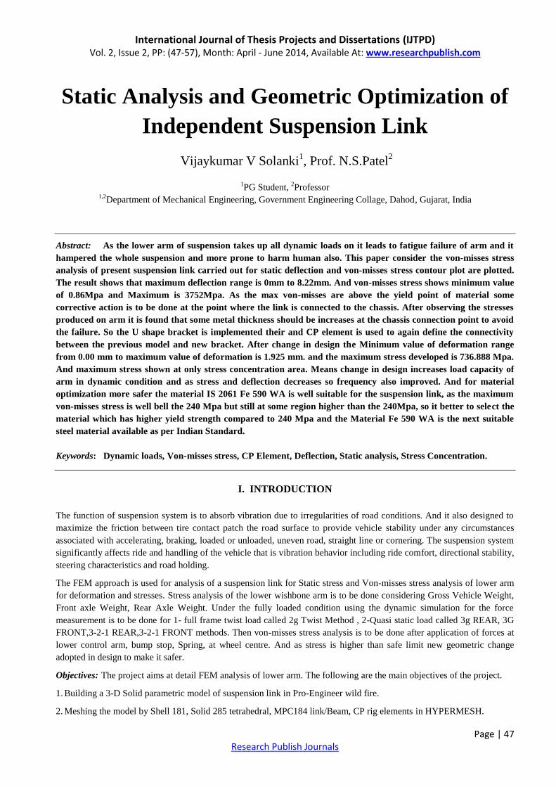
As a prerequisite to the finite element model is the physical geometry of the part i.e. the suspension link we have created
using Proe-Wildfire software.
Fig .1. Solid Modeling of Suspension link
III. MESH GENERATION
Meshing generally falls in two categories depending on the geometry of the element. For a 3D machine element of regular
shape, solid meshing is sufficient, but for irregular geometries we have to first use surface meshing and then solid
meshing.
The HYPERMESH meshing was created using the imported CAD geometry. This was undertaken by using either manual
or auto meshing techniques. Once the mesh has been created it is checked for free edge duplicates and normal. The
element quality is also checked for aspect ratio, wrap angle, skew angle and taper. Once assured with a safe and sound
surface meshing our next step is to import the model in ANSYS for solid meshing.
SOLID285
SOLID285 element is a lower-order 3-D, 4-node mixed u-P element. The element has a linear displacement and
hydrostatic pressure behavior. The element is suitable for modeling irregular meshes (such as those generated by various
CAD/CAM systems) and general materials (including incompressible materials).
The element has plasticity, hyperelasticity, creep, stress stiffening, large deflection, and large strain capabilities.
MPC184
Multipoint Constraint Elements: Rigid Link, Rigid Beam, Slider, Spherical, Revolute, Universal MPC184 comprises a
general class of multipoint constraint elements that implement kinematic constraints using Lagrange multipliers. The
elements are loosely classified here as “constraint elements” and “joint elements”. The rigid part of the structure may be
modeled using the MPC184 Link/Beam elements, while the moving parts may be connected with the MPC184 slider,
International Journal of Thesis Projects and Dissertations (IJTPD) Vol. 2, Issue 2, PP: (47-57), Month: April - June 2014, Available At: www.researchpublish.com
Page | 49 Research Publish Journals
spherical, revolute, or universal joint element. Since these elements are implemented using Lagrange multipliers, the
constraint forces and moments are available for output purposes. This element is used to define the connectivity between
the point of application of force and the nodded on the surface of the structural member.
SHELL 181
Building a shell model requires mid-plane surfaces in one form or another. For single parts and simple sheet metal
assemblies, some CAD systems that have a pre-processor integrated into the interface can automatically compress a solid
model into a mid-plane surface model. As the suspension model has lower thickness so mid plane surface generation used
in ANSYS.
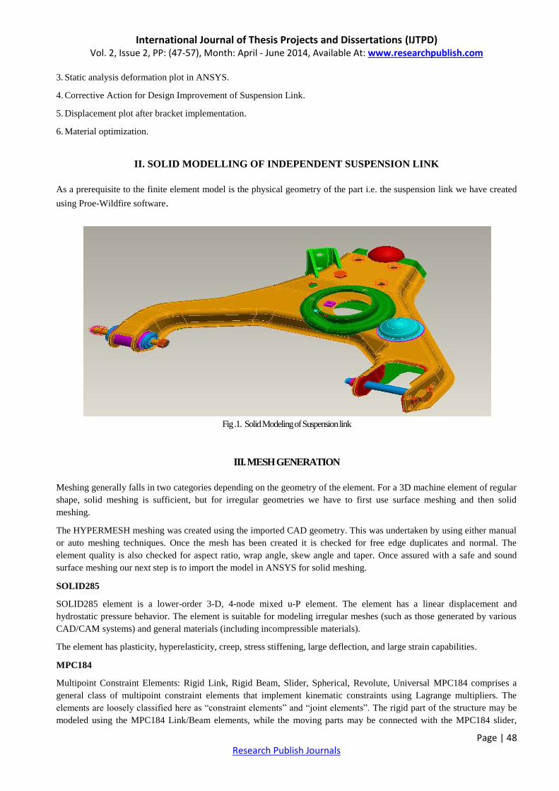
CP rig ELEMENT:
This element Defines (or modifies) a set of coupled degrees of freedom. Coupling degrees of freedom into a set causes the
results calculated for one member of the set to be the same for all members of the set. Coupling can be used to model
various joint and hinge effects.
Fig.2. meshed model of suspension link (top view)
Fig.3. Meshed model of suspension link (bottom view)

International Journal of Thesis Projects and Dissertations (IJTPD) Vol. 2, Issue 2, PP: (47-57), Month: April - June 2014, Available At: www.researchpublish.com
Page | 50 Research Publish Journals
IV. MECHANISM AND BOUNDARY CONDITION
Force and torque applied on the structural component is based on the mechanism explained on the testing method. The
boundary conditions implemented on the component are as under discussed.
At pin position- Rot X, Rot Y, Rot Z, Trans Y and Trans Z is allowed. Translation of X is not allowed. 𝐹𝑥, 𝐹𝑦, 𝐹𝑧
is applied at base node of MPC184.
At spring seat- Force in X, Y, Z is applied at the base node of MPC184.
Bump-stop- Force in X, Y, Z is applied at the base node of MPC184.
Bolt holes- Centre of tetrahedral element is connected by MPC184 element is connected by MPC184 element and
wheel centre is fixed.
Force in Z direction is applied on spindle of wheel centre.
Fig.4. Force layout of Independent Suspension Link
Fig.5. Force Layout (Constraint based)

International Journal of Thesis Projects and Dissertations (IJTPD) Vol. 2, Issue 2, PP: (47-57), Month: April - June 2014, Available At: www.researchpublish.com
Page | 51 Research Publish Journals
V. STATIC ANALYSIS DEFORMATION PLOT
Fig.6. Static analysis deformation plot
Fig.7. Static analysis von-misses stress plot
The result shows that maximum deflection is 0mm to 8.22mm. And von-misses stress minimum in .86Mpa and Maximum
is 3752Mpa. The component is check for von-misses stress applying above forces and boundary condition. And its
maximum deformation is cross checked whether it is going out of limit of max. Deformation observed in natural
frequency steps.
As the max von-misses are above the yield point of material some corrective action is to be done at the point where the link is
connected to the chassis.

International Journal of Thesis Projects and Dissertations (IJTPD) Vol. 2, Issue 2, PP: (47-57), Month: April - June 2014, Available At: www.researchpublish.com
Page | 52 Research Publish Journals
V. CORRECTIVE ACTION FOR DESIGN IMPROVEMENT OF SUSPENSION LINK
After observing the stresses it is found that some metal thickness should be increases at the chassis connection point to
avoid the failure. So the U shape bracket is implemented their and CP element is used to again define the connectivity
between the previous model and new bracket.
Fig.8. Design changed model with bracket
Fig.9. Enlarged view of U shape bracket
Fig10. Enlarged view of various U shape brackets.
International Journal of Thesis Projects and Dissertations (IJTPD) Vol. 2, Issue 2, PP: (47-57), Month: April - June 2014, Available At: www.researchpublish.com
Page | 53 Research Publish Journals
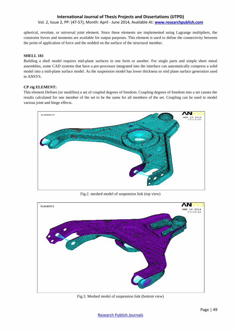
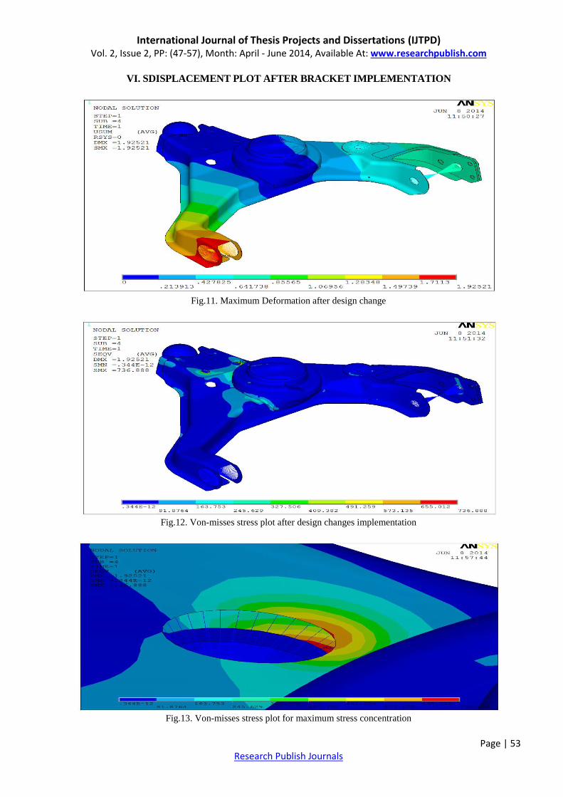
VI. SDISPLACEMENT PLOT AFTER BRACKET IMPLEMENTATION
Fig.11. Maximum Deformation after design change
Fig.12. Von-misses stress plot after design changes implementation
Fig.13. Von-misses stress plot for maximum stress concentration
International Journal of Thesis Projects and Dissertations (IJTPD) Vol. 2, Issue 2, PP: (47-57), Month: April - June 2014, Available At: www.researchpublish.com
Page | 54 Research Publish Journals
It shows that after change in design the Minimum value of deformation is range from 0.00 mm to 1.925 mm. which is
smaller compared to 8.22mm of present design. And the maximum stress developed is 736.888 Mpa is also lower
compared to 3752Mpa. Means change in design increases load capacity of arm in dynamic condition and as stress and
deflection decreases so frequency also improved.
The maximum stress which is showing in the above figure 13 is not appear in the actual case, this is because of stress
concentration and hence the stress is very low after the design improvement.
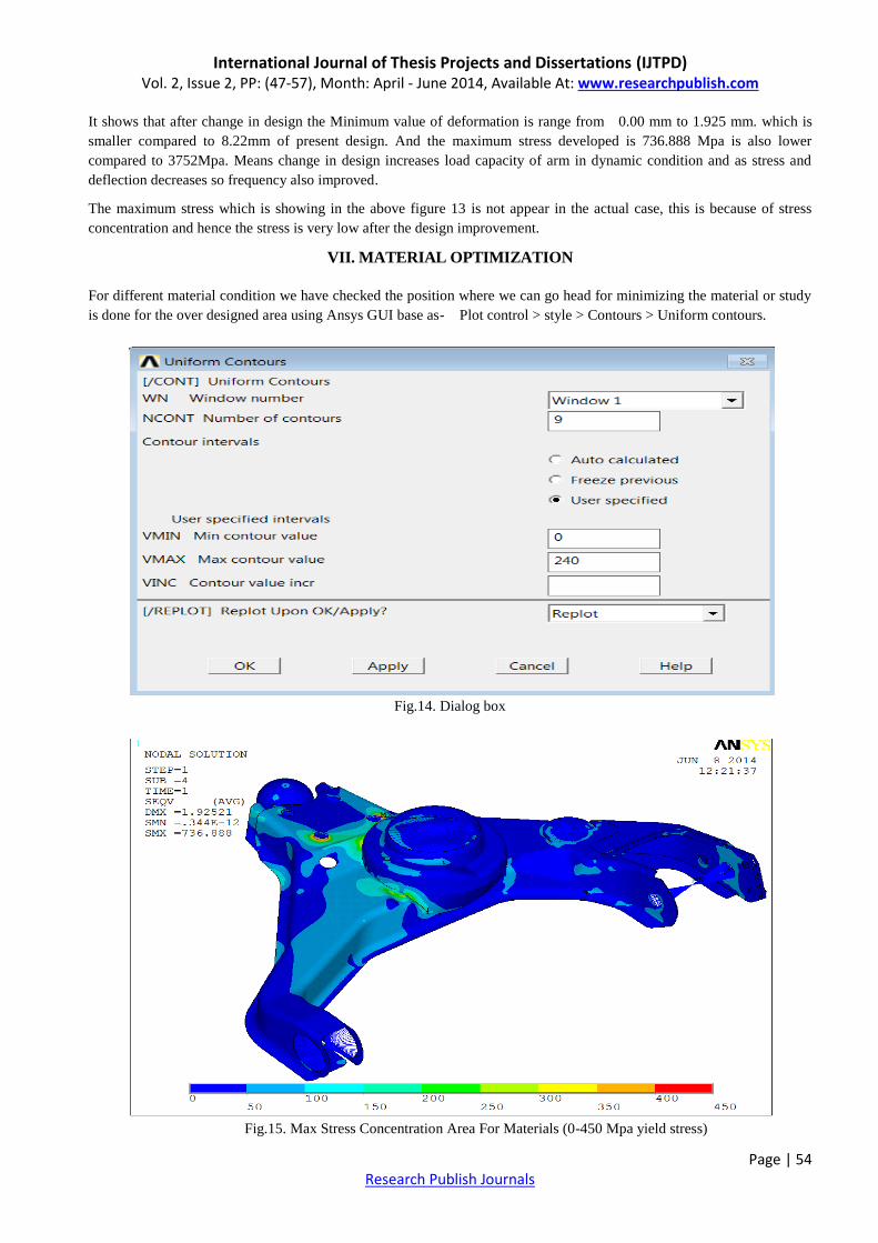
VII. MATERIAL OPTIMIZATION
For different material condition we have checked the position where we can go head for minimizing the material or study
is done for the over designed area using Ansys GUI base as- Plot control > style > Contours > Uniform contours.
Fig.14. Dialog box
Fig.15. Max Stress Concentration Area For Materials (0-450 Mpa yield stress)

International Journal of Thesis Projects and Dissertations (IJTPD) Vol. 2, Issue 2, PP: (47-57), Month: April - June 2014, Available At: www.researchpublish.com
Page | 55 Research Publish Journals
For steel material of IS 2062 Fe 590 material.
Table. I. Material properties of IS 2062 Fe 590
Fig.16. Max Stress Concentration Area for Materials (0-250 Mpa yield stress) for material steel
Fe 410 WA which has a yield strength of 250 Mpa.
Table. II Material properties of IS 2062 Fe 410 WA

International Journal of Thesis Projects and Dissertations (IJTPD) Vol. 2, Issue 2, PP: (47-57), Month: April - June 2014, Available At: www.researchpublish.com
Page | 56 Research Publish Journals
Fig. N. Max Stress Concentration Area for Materials (0-85 Mpa yield stress)
It seems the to make more safer the material IS 2061 Fe 590 WA is well suitable for the suspension link, as the maximum
von-misses stress is well bell the 240 Mpa but still at some region higher than the 240Mpa, so it better to select the
material which has higher yield strength compared to 240 Mpa and the Material Fe 590 WA is the next suitable steel
material available as per Indian Standard.
VIII. DICUSSION AND CONCLUSION
From the deformation plot, unstressed plot of Independent suspension link without bracket represent maximum value of
deformation as = 8.22 mm and maximum von-misses stresses as 3752 MPa so the object may undergo failure during
repetitive operating condition, so the different design has been changed to improve the strength of the suspension there are
different shape brackets provided near the chassis connection point reduces the stress level to below 245MPa so the
decrease in maximum von-misses stress value conclude our work.
1. Dynamic Load carrying capacity of suspension link increases as it stand to higher stress value.
2. The maximum stress which is shown is developed due to stress concentration at point is not appear in the actual case,
and hence the stress is very low after the design improvement.
IX. FUTURE SCOPE
As the physical model of component shows a coil spring and shock absorber is also connected to the control arm by a
spring seat, we can go ahead in future to do the fatigue analysis of the part by considering the vibration mode induced by
road irregularities and damping also can be induced in the study by considering the shock absorber and the load mounted
on both spring and damper.
The application of topography and shape optimization technique to the design of complete link may reduce the weight of
the component. The sequence of optimization should follow the following three basic procedures.
1) Sizing (Gauge) optimization has to be done to redesign complete link.
2) If the weight is not satisfactory after gauge optimization then we can try for shape optimization.
All this option we are presenting to the designer to enable him to make a decision based on manufacturing on other
constraint. Although these solution seen to be a good result. Topography optimization may lead to least weight of the
component with the plenty of manufacturing operation.
ACKNOWLEDGEMENT
We are very thankful to our guide Prof. N.S.Patel for great technical guideline and Head of department Prof. R.I.Patel for
providing all encouragement.

International Journal of Thesis Projects and Dissertations (IJTPD) Vol. 2, Issue 2, PP: (47-57), Month: April - June 2014, Available At: www.researchpublish.com
Page | 57 Research Publish Journals
REFERENCES
[1] Ansys Inc., “Ansys 15 Documentation, Structural Analysis Guide”, Swanson Analysis System, United States.
[2] Bathe, K.J., 2002, “Finite Elements Procedures”, Prentice-Hall of India Private Limited, New Delhi,
[3] “Finite Element Topography and shape optimization of Jounce Bumper Bracket”, Murali M. R. Krishna 2002, SAE
Inc, Dana Corp.
[4] “CAE Structural Approach”, Lotus, Ultra Light Steel Auto Suspension 2004.
[5] Villams Adams, “Building Better Product with Finite Element Analysis”.
[6] Chandrupatla, T. R., Belegundu, A. D., 1999 “Introduction to Finite Elements in Engineering”, Prentice-Hall of
India Private Limited, New Delhi.
[7] Edmund, F. G., Salinas, A. R., 2003, “Introduction to Formula SAE Suspension and Frame Design”, SAE, Paper No.
971584.
[8] Fagan, M.F, 2001, “Finite Element Analysis Theory and Practice”, University of Hall, Logman Scientific and
Technology.
[9] Hyper Mesh Users Guide, Altair Engineering, Inc.
[10] Mahindra Newsletters, Issue 2, April-June 2005, Roma Balwani, Mumbai
[11] Design and Fabrication of MRF Damper for Indian cars by Mohit Bansal and Pranav Jaiswal Department of
Mechanical Engineering Indian Institute of Technology Delhi May 2013
[12] Dynamic modelling of the double wishbone motor-vehicle suspension system by Hazem Ali Attia. European Journal
of Mechanics A/Solids 21 (2002) 167–174.
[13] Suspension arm design based on stochastic optimization approach by Hemin M. Mohyaldeen1, M. M. Rahman1, 2
M. M. Noor1 and K. Kadirgama1. 1.Faculty of Mechanical Engineering, Pekan Campus, University Malaysia
Pahang 26600 UMP, Kuantan, Malaysia 2.Automotive Excellence Center, Gambang Campus, University Malaysia
Pahang, 26300 UMP, Kuantan, and Pahang, Malaysia.
[14] Prediction of fatigue life of lower arm subjected to variable amplitude loading by Z. Husin, M.M. Rahman, K.
Kadirgama, M.M. Noor and Rosli A.Bakar. Faculty of Mechanical Engineering, Malaysia Pahang.
[15] Dynamic Analysis of an Automobile Lower Suspension Arm Using Experiment and Numerical Technique by S.
Abdullah1, N.A. Kadhim, A.K. Ariffin and M. Hosseini Universiti Kebangsaan Malaysia,Taylor’s University
College Malaysia.
[16] Experimental and finite element analysis of left side lower wishbone arm of independent suspension system by Prof.
A.M. Patil, Prof. A.S.Todkar, Prof. R.S.Mithari, Prof. V.V.Patil. Article info: IOSR journal of mechanical and civil
engineering (IOSR-JMCE). E-ISSN: 2278-1684, p-2320-334X, VOLUME 7, PP 43-48.
[17] Dynamic Analysis of Vehicle Arm Based on Finite Element Approach by Hemin M M, Rahman M M and Omar R
M. Faculty of Mechanical Engineering. University Pahang. Malaysia, automotive Engineering Centre, University
Pahang, Malaysia. Article info: journal of advanced science and engineering research 1(2011)124-136.
[18] Geometry optimization of double wishbone suspension system via genetic algorithm for handling improvement,
Kaunas, Lithuania, By Author(s): Mehdi Mahmoodi-Kaleibar, Amin Paykani, Amir Afkar. Public establishment
VIBROENGINEERING. Geliu ratas 15A, LT-50282,
[19] Optimization of suspension system of off-road vehicle for vehicle performance improvement BY M. Mahmoodi-
Kaleibar, I. lavanshir, K. Asadi, A. Afkar, A. Paykani Article info.DOI: 10.1007/s11771-013-1564-1 J. Cent. South
University (2013) 20: 902-910.
[20] Design And Optimization Of Sheet Metal Control Arm For Independent Suspension System by P. Nagarjuna and K.
Devaki Devi, (IJERA) ISSN: 2248-9622 www.ijera.com Volume 2, Issue5, September- October 2012, pp.535-539.
[21] Designs and Optimizations of Active and Semi-Active Non-linear Suspension Systems for a Terrain Vehicle by
Shpetim Lajqi and Stanislav Pehan. Journal of Mechanical Engineering 58(2012)12, 732-743.