Embed Size (px)
Citation preview
Static and dynamic properties of a motorcycle frame: experimental and numerical approach
M. Bocciolone, F. Cheli, M. Pezzola & R. Viganò
Department of Mechanical Engineering, Politecnico di Milano
Abstract It is well known how the main frame of a motorcycle plays an important rule in vehicle dynamics. In order to understand the main influences of this component, a dedicated test rig was design and realized. Numerical and experimental experiences were done with the aim to identify static stiffness, natural frequencies and vibration modes of a motorcycle frame. A dedicated test rig was designed and realized in order to load the chassis in torsional and flexural configuration, both within and without the engine. By the use of a hydraulic actuator, displacement controlled, a load ramp was applied to stress the frame in elastic yield, as in real conditions, and the structure flexure was measured with laser transducers. The test rig components were monitored by the use of laser transducers in order to include constraints compliances into the identification step. In this phase, the flexural and torsional static stiffness of the main frame were identified, paying attention to distinguish the engine’s contribute. A modal analysis, processing experimental data, was performed using the frequency response function measured in six different points of the frame. Natural frequencies, deflection modes and damping were identified. At the same time, a detailed numerical model of the main frame was developed. It was processed by the use of the finite element method in order to reproduce the experimental experiences. Numerical and experimental results were compared to validate the model of the chassis. All the obtained parameters are mainly being used in a dynamic study of motorcycle behaviour. Firstly, identified stiffness will be implemented as concentred springs, obtaining a significant model of the vehicle. Following this a multi-body model of the vehicle will be defined, including deformability of structures, using modal coordinates, and just introducing the most interesting modes. Keywords: motorcycle frame, test rig, torsional stiffness, flexural stiffness, natural frequencies, modal analysis, measurements.
© 2005 WIT Press WIT Transactions on Modelling and Simulation, Vol 41, www.witpress.com, ISSN 1743-355X (on-line)
Computational Methods and Experimental Measurements XII 517
1 Introduction
Motorcycles are characterized by forms of instability that can compromise the safety of the rider. Previously investigations have indicated three major instabilities that occur during the vehicle running [1, 2, 3]. First, a hypercritic (non oscillatory) instability, commonly defined capsize mode, represented by the tendency of the motorcycle to fall down at low speed. Then, two oscillatory modes follow. Weave is the first one, occurring in a frequency band of 2 – 4 Hz. This mode involves the steer, roll and yaw motions. Wobble is the second one, characterized by 6 – 8 Hz range of frequencies, involving mainly steering oscillations. Many previously studies were done to investigate frame importance on dynamic response. Firstly, Sharp [4,5] included the rear swing arm flexibility as degree of freedom in a linearized model, built to describe the straight line behaviour. The numerical results showed a deterioration of weave mode adopting very low value of stiffness, in practice associated with worn swing arm bearings. Later, numerically by Verma [6] and experimentally by Roe and Thorpe [7], front forks and main frame flexibility were taken into account. From theoretical study of Sharp and Alstead [8] and Spierings [9] it was demonstrated that wobble instability is directly related to the stiffness and deflection modes of connections between front and real wheel and chassis. For instance, a competition supermotard vehicle is required to work under selective and variable requirements: to have a good manoeuvrability on low friction surfaces, like off road, and to be stable on medium - high speed cornering on high friction surfaces. In these conditions, the synergy between suspensions and main frame is the key aspect. During a high roll angle cornering on high friction passage, the torsion stiffness works in series with the front fork. These absorb the only component of road irregularity directed as the telescopic axes, while the frame, as equivalent torsion spring, absorbs the normal component to the same axis. This capability is useful to guarantee the adherence in the passages between low and high friction surface. Moreover, a modal analysis of the chassis, with particular attention to high frequency domain, is used for comfort studies. The engine rotation, all over the range use, can be close to high natural frequencies of local area of chassis, causing vibration transmission to the whole structure and a probable fatigue local rupture of a connection between frame and engine. All the estimated static and dynamic parameters of the structure will be introduced, in the following of the research, in a fully non linear model of vehicle, used to study the handling, stability of the motorcycle in specific running condition.
2 Experimentation
The importance of experimental investigation of structural parameters had driven to design and realize a dedicated test rig (fig.1). A research was executed to analyse different conditions of stress in relation to the various situations that
© 2005 WIT Press WIT Transactions on Modelling and Simulation, Vol 41, www.witpress.com, ISSN 1743-355X (on-line)
518 Computational Methods and Experimental Measurements XII
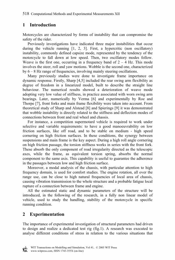
occur in real exercise of motorcycle. Torsion configuration reproduces the effect of cornering, while flexural one reproduces the cases of braking, acceleration and jump. The interfaces between frame and test structure was studied to agree most kind of motorcycles’ chassis.
Figure 1: torsion test (A), flexural test (B).
2.1 Test rig description
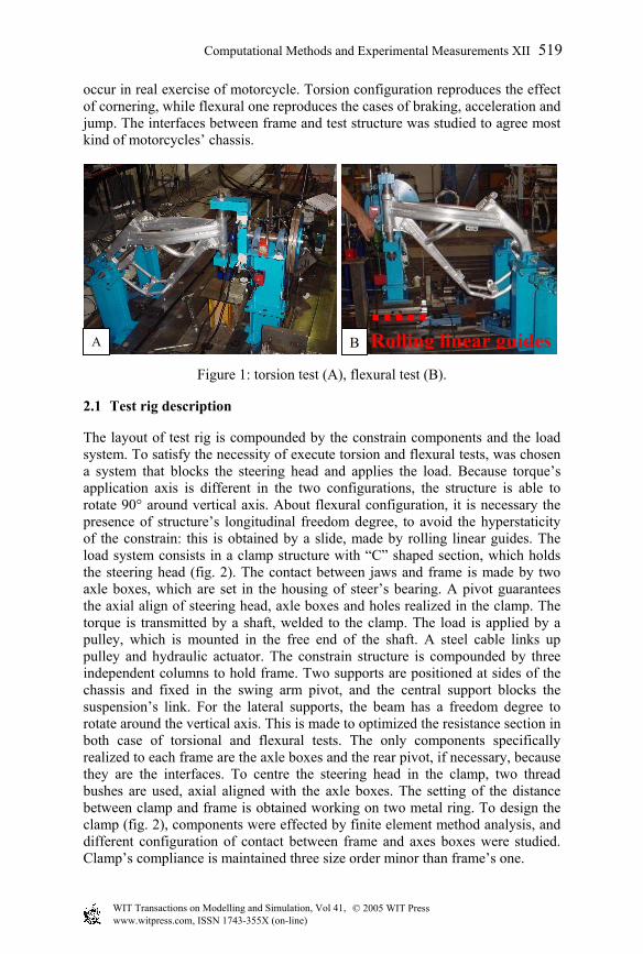
The layout of test rig is compounded by the constrain components and the load system. To satisfy the necessity of execute torsion and flexural tests, was chosen a system that blocks the steering head and applies the load. Because torque’s application axis is different in the two configurations, the structure is able to rotate 90° around vertical axis. About flexural configuration, it is necessary the presence of structure’s longitudinal freedom degree, to avoid the hyperstaticity of the constrain: this is obtained by a slide, made by rolling linear guides. The load system consists in a clamp structure with “C” shaped section, which holds the steering head (fig. 2). The contact between jaws and frame is made by two axle boxes, which are set in the housing of steer’s bearing. A pivot guarantees the axial align of steering head, axle boxes and holes realized in the clamp. The torque is transmitted by a shaft, welded to the clamp. The load is applied by a pulley, which is mounted in the free end of the shaft. A steel cable links up pulley and hydraulic actuator. The constrain structure is compounded by three independent columns to hold frame. Two supports are positioned at sides of the chassis and fixed in the swing arm pivot, and the central support blocks the suspension’s link. For the lateral supports, the beam has a freedom degree to rotate around the vertical axis. This is made to optimized the resistance section in both case of torsional and flexural tests. The only components specifically realized to each frame are the axle boxes and the rear pivot, if necessary, because they are the interfaces. To centre the steering head in the clamp, two thread bushes are used, axial aligned with the axle boxes. The setting of the distance between clamp and frame is obtained working on two metal ring. To design the clamp (fig. 2), components were effected by finite element method analysis, and different configuration of contact between frame and axes boxes were studied. Clamp’s compliance is maintained three size order minor than frame’s one.
A B Rolling linear guides
© 2005 WIT Press WIT Transactions on Modelling and Simulation, Vol 41, www.witpress.com, ISSN 1743-355X (on-line)
Computational Methods and Experimental Measurements XII 519
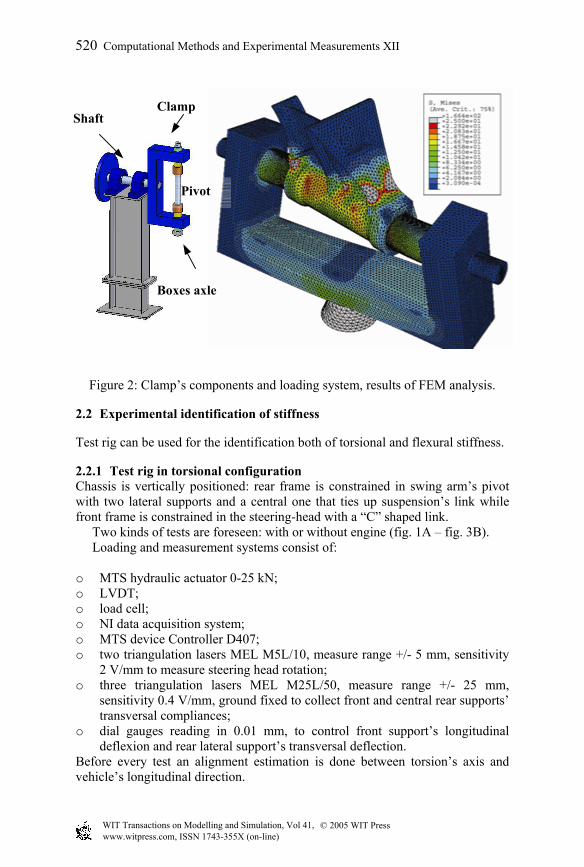
Figure 2: Clamp’s components and loading system, results of FEM analysis.
2.2 Experimental identification of stiffness
Test rig can be used for the identification both of torsional and flexural stiffness.
2.2.1 Test rig in torsional configuration Chassis is vertically positioned: rear frame is constrained in swing arm’s pivot with two lateral supports and a central one that ties up suspension’s link while front frame is constrained in the steering-head with a “C” shaped link. Two kinds of tests are foreseen: with or without engine (fig. 1A – fig. 3B). Loading and measurement systems consist of: o MTS hydraulic actuator 0-25 kN; o LVDT; o load cell; o NI data acquisition system; o MTS device Controller D407; o two triangulation lasers MEL M5L/10, measure range +/- 5 mm, sensitivity
2 V/mm to measure steering head rotation; o three triangulation lasers MEL M25L/50, measure range +/- 25 mm,
sensitivity 0.4 V/mm, ground fixed to collect front and central rear supports’ transversal compliances;
o dial gauges reading in 0.01 mm, to control front support’s longitudinal deflexion and rear lateral support’s transversal deflection.
Before every test an alignment estimation is done between torsion’s axis and vehicle’s longitudinal direction.
Clamp Shaft
Pivot
Boxes axle
© 2005 WIT Press WIT Transactions on Modelling and Simulation, Vol 41, www.witpress.com, ISSN 1743-355X (on-line)
520 Computational Methods and Experimental Measurements XII
Data elaboration is based on front frame’s rotation (fig. 3A).
−=
int
21L
xxarctgθ (1)
where: o x1 = steering head’s displacement; o x2 = steering head’s displacement; o Lint = laser inter axis.
Torsional stiffness mathematical formulation:
rFM ⋅= (2) θ/Mtk = (3)
where: o M = applied torque; o F = tangentially force on pulley applied by steel cable; o r = pulley’s radius; o kt = torsional stiffness; o θ = steering head rotation.
Figure 3: measurement’s scheme (A), torsion test: frame with engine (B).
Every test is composed by 3 loading ramps, 4 times repeated, with uploading application speed 1 mm/s and downloading application speed 2 mm/s. Sampling frequency acquisition is set to 10 Hz. Torque peak applied depends on the kind of test: 500 Nm for simple frame and 1000 Nm for frame with engine. These values are due to an investigation about loads in supermotard competition, with the aim to be in elastic range. Torsional stiffness value is obtained by linear regression, upon applied torque, angular displacement and constraint compliance calculations.
X1
X2
A B
θ
L int
© 2005 WIT Press WIT Transactions on Modelling and Simulation, Vol 41, www.witpress.com, ISSN 1743-355X (on-line)
Computational Methods and Experimental Measurements XII 521
2.2.2 Test rig in flexural configuration Chassis is vertically positioned: the whole experiment can be conducted in the same way of torsional one. The only difference are constituted by a slide under the 90° rotated front support in horizontal plan, with the aim of leaving a longitudinal degree of liberty and the missing central rear support to allow frame’s rotation around swing arm’s pivot (fig. 1B).
2.3 Experimental modal identification
The first natural frequencies of the chassis were identified. The structure was elastically suspended. About the excitation, an impact hammer was used. It is possible to generate an impulse signal characterised by an almost flat spectrum all over the desired frequency domain. Six piezo - accelerometers were placed in six different points of the frame. Those points were chosen after a critical analysis of numerical simulations responses, conduced on a detailed model of the chassis (referred to chapter 3), processed by a linear analysis with finite element approach. In particular three sensors were placed on the steering head, one on the lower area of the frame and two on the rear area. Technical features of sensors were: o six monoaxial accelerometers +/- 50 g, full scale, transversal sensitivity <=1
%, natural frequency 22 kHz, temperature range 0 - 65 °C; o piezoelectric dynamometric hammer, range 0-5000 lb, mass 265g; A single input single output (SISO) system is characterised through a frequency response function (FRF). Ideally the FRF is the ratio between the output response and the input, both expressed in frequency domain. During an experimental identification it is necessary to estimate natural frequencies, related vibration modes and damping factors. The H1xy estimator was used, because insensitive to noise in output signals, referred to ten impulse repetitions as follow:
;1yy
xyxyxy G
GHFRF =≅ (4)
where: o y(t), x(t) = respectively the input (hammer) and output (accelerometer) in
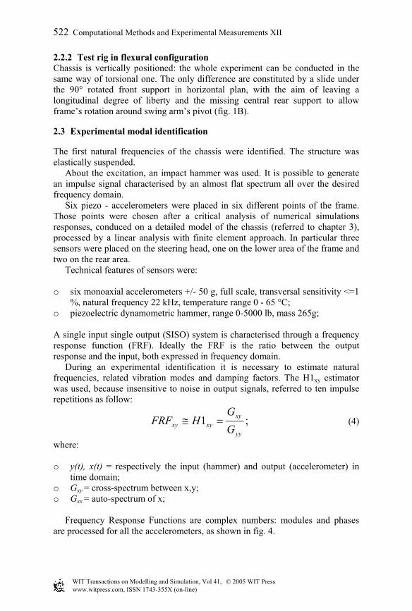
time domain; o Gxy = cross-spectrum between x,y; o Gxx = auto-spectrum of x; Frequency Response Functions are complex numbers: modules and phases are processed for all the accelerometers, as shown in fig. 4.
© 2005 WIT Press WIT Transactions on Modelling and Simulation, Vol 41, www.witpress.com, ISSN 1743-355X (on-line)
522 Computational Methods and Experimental Measurements XII
0 200 400 600 800 10000
10
20
30
[Hz]
FR
F M
OD
ULE
[g/N
]
Acc. 1Acc. 2Acc. 3Acc. 4Acc. 5Acc. 6
Figure 4: FRF of the six accelerometers.
0 2 4 6 8 10-100
-80
-60
-40
-20
0
20
40
60
80
t [s]
Acc
eler
atio
n [g
]
Figure 5: Mono frequency decay.
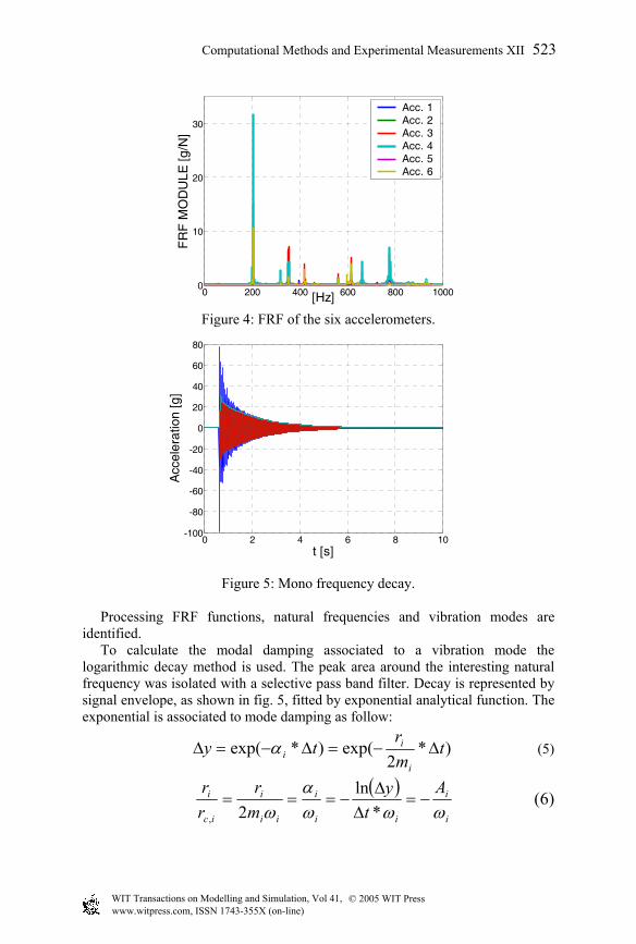
Processing FRF functions, natural frequencies and vibration modes are identified. To calculate the modal damping associated to a vibration mode the logarithmic decay method is used. The peak area around the interesting natural frequency was isolated with a selective pass band filter. Decay is represented by signal envelope, as shown in fig. 5, fitted by exponential analytical function. The exponential is associated to mode damping as follow:
)*2
exp()*exp( tmr
tyi
ii ∆−=∆−=∆ α (5)
( )i
i
ii
i
ii
i
ic
i At
ymr
rr
ωωωα
ω−=
∆∆
−===*
ln2,
(6)
© 2005 WIT Press WIT Transactions on Modelling and Simulation, Vol 41, www.witpress.com, ISSN 1743-355X (on-line)
Computational Methods and Experimental Measurements XII 523
Steering head
Boxed anterior post
Crossbars andlateral plates
Anterior box
Perimetric coupledtubes
where, respectively, ri ,mi , ωi are i-mode damping, mass and natural frequency and Ai is the angular coefficient of the signal envelope, expressed in logarithmic coordinates.
3 Numerical model: finite elements analysis
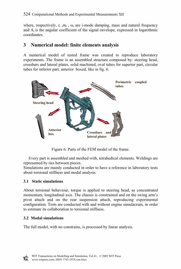
A numerical model of tested frame was created to reproduce laboratory experiments. The frame is an assembled structure composed by: steering head, crossbars and lateral plates, solid machined, oval tubes for superior part, circular tubes for inferior part, anterior boxed, like in fig. 6.
Figure 6: Parts of the FEM model of the frame.
Every part is assembled and meshed with, tetrahedical elements. Weldings are represented by ties between pieces. Simulations are mainly conducted in order to have a reference in laboratory tests about torsional stiffness and modal analysis.
3.1 Static simulations
About torsional behaviour, torque is applied to steering head, as concentrated momentum, longitudinal axis. The chassis is constrained and on the swing arm’s pivot attach and on the rear suspension attach, reproducing experimental configuration. Tests are conducted with and without engine simulacrum, in order to estimate its collaboration to torsional stiffness.
3.2 Modal simulations
The full model, with no constrains, is processed by linear analysis.
© 2005 WIT Press WIT Transactions on Modelling and Simulation, Vol 41, www.witpress.com, ISSN 1743-355X (on-line)
524 Computational Methods and Experimental Measurements XII
4 Results
In the following a summary of the obtained results is represented.
Table 1: Torsional stiffness: experimental and numerical results.
Experimental Numerical Frame 1050 Nm/° 1170 Nm/°
Frame + engine 1320 Nm/° 1380 Nm/°
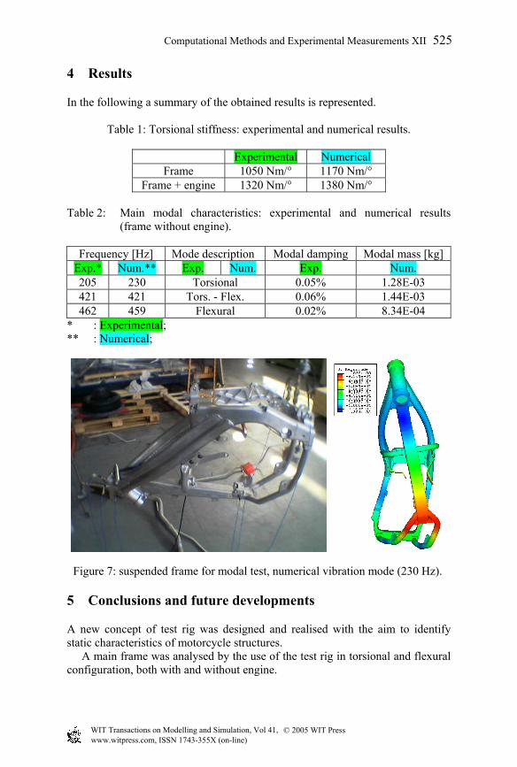
Table 2: Main modal characteristics: experimental and numerical results (frame without engine).
Frequency [Hz] Mode description Modal damping Modal mass [kg]
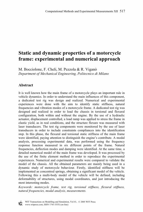
Exp.* Num.** Exp. Num. Exp. Num. 205 230 Torsional 0.05% 1.28E-03 421 421 Tors. - Flex. 0.06% 1.44E-03 462 459 Flexural 0.02% 8.34E-04
* : Experimental; ** : Numerical;
Figure 7: suspended frame for modal test, numerical vibration mode (230 Hz).
5 Conclusions and future developments
A new concept of test rig was designed and realised with the aim to identify static characteristics of motorcycle structures. A main frame was analysed by the use of the test rig in torsional and flexural configuration, both with and without engine.
© 2005 WIT Press WIT Transactions on Modelling and Simulation, Vol 41, www.witpress.com, ISSN 1743-355X (on-line)
Computational Methods and Experimental Measurements XII 525
Modal identification was done on the same structure to measure natural frequencies, relative vibration modes and modal damping. A numerical model was built and validated, in both stiffness and frequency studies. Differences, between experimental and numerical results, are imputable to the attributes of the geometrical model. It is underlined that tetrahedical four nodes elements were used to be able to easily manipulate the model. The use of those elements causes the tightening of the structure, with particular regards to low frequency modes. This is the main reason why the numerical model is characterised by a higher stiffness. Furthermore, model’s welding roads, that tie components, don’t have mass and don’t add stiffness. Real constraints have micro-displacements and actions of lock, that aren’t implemented in the numerical simulations. A modelling of a numerical ten nodes elements frame is in process to investigate the contributes of numerical tightening on frequency response. Flexural simulations of the chassis are in process, both with and without engine. A full vehicle model will be developed introducing the tested structures capabilities, firstly by extra freedom degrees, connected to the main frame by local torsional springs, following by the assemblage of modal masses, damping and stiffness matrices.
References
[1] R.A. Wilson-Jones, Steering and stability of single-track vehicles, Proc. Inst. Mech. Engrs (AD) part 4, (1951), 191-199.
[2] V. Cossalter, Cinematica e dinamica della motocicletta,edizioni progetto, ISBN 88-87331-03-0
[3] E. Dohring, Steering wobble in single-track vehicles, A.T.Z., Vol. 58, No. 10 (1956), 282-286.
[4] R.S Sharp, The influence of the suspension system on motorcycle weave mode oscillations,Vehicle System Dynamics, Vol. 5 (1976), 147-154.
[5] R.S Sharp, The influence of frame flexibility on the lateral stability of motorcycles, Jour. Mech. Engng. Sci., Vol. 15, No. 2 (1974), 117-120.
[6] M.K. Verma, Theoretical and experimental investigation of motorcycle dynamic, Doctoral dissertation, University of Michigan, Ann Arbor, 1978
[7] G.E. Roe and T.E. Thorpe, A solution of the low speed wheel flutter instability in motorcycles, Jour. Mech. Engng. Sci., Vol. 18, No. 2 (1976), 57-65.
[8] R.S Sharp, C.J Alstead, The influence of structural flexibilities on the straight-running stability of motorcycles, Veh. Syst. Dyn., Vol. 9 (1980), 327-357.
[9] P.T.J. Spierings, The effects of lateral front fork flexibility on the vibrational modes of the straight-running single track vehicles, Veh. Syst. Dyn., Vol. 10 (1981)
© 2005 WIT Press WIT Transactions on Modelling and Simulation, Vol 41, www.witpress.com, ISSN 1743-355X (on-line)
526 Computational Methods and Experimental Measurements XII