Embed Size (px)
Citation preview
Lecture 15
February 19, 2018
Statics - TAM 210 & TAM 211
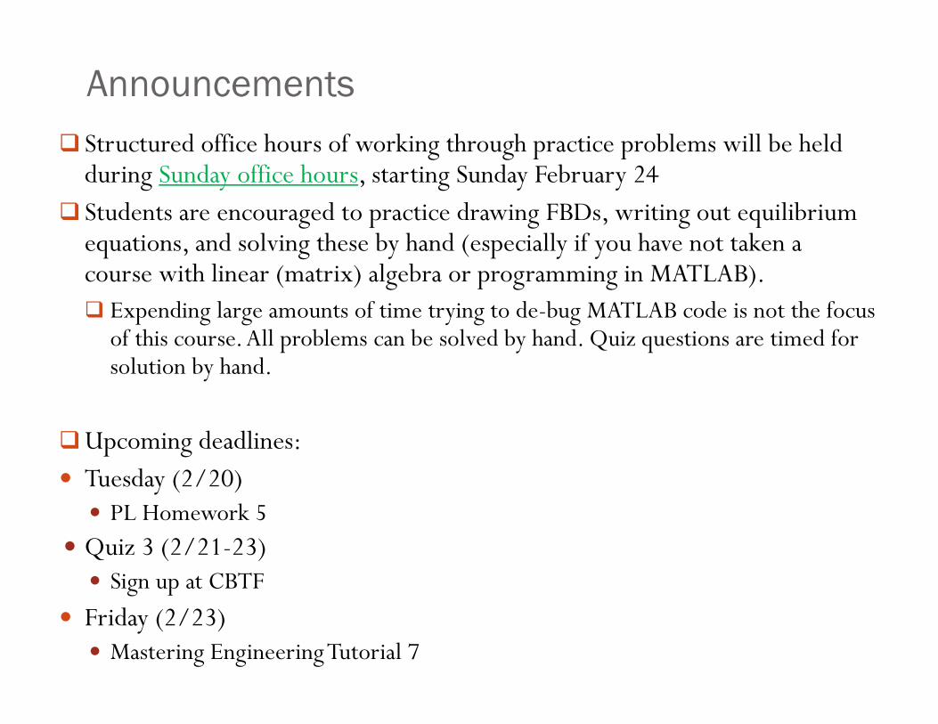
Announcements Structured office hours of working through practice problems will be held
during Sunday office hours, starting Sunday February 24 Students are encouraged to practice drawing FBDs, writing out equilibrium
equations, and solving these by hand (especially if you have not taken a course with linear (matrix) algebra or programming in MATLAB). Expending large amounts of time trying to de-bug MATLAB code is not the focus
of this course. All problems can be solved by hand. Quiz questions are timed for solution by hand.
Upcoming deadlines: Tuesday (2/20) PL Homework 5
Quiz 3 (2/21-23) Sign up at CBTF
Friday (2/23) Mastering Engineering Tutorial 7
Focus on 2D problems
Sections 5.1-5.4, 5.7
TAM 211 students will cover 3D problems (sections 5.5-5.6) in week 13
Chapter 5: Equilibrium of Rigid Bodies
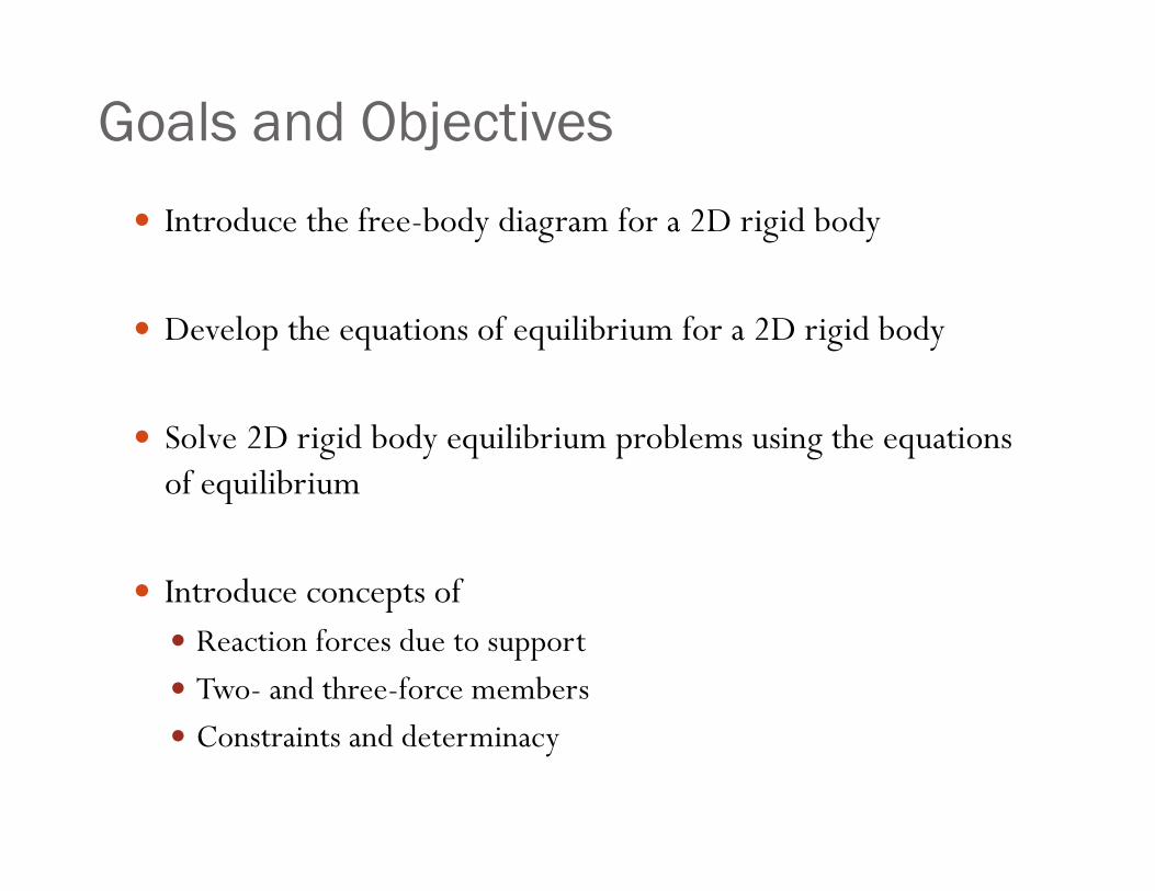
Introduce the free-body diagram for a 2D rigid body
Develop the equations of equilibrium for a 2D rigid body
Solve 2D rigid body equilibrium problems using the equations of equilibrium
Introduce concepts of Reaction forces due to support Two- and three-force members Constraints and determinacy
Goals and Objectives
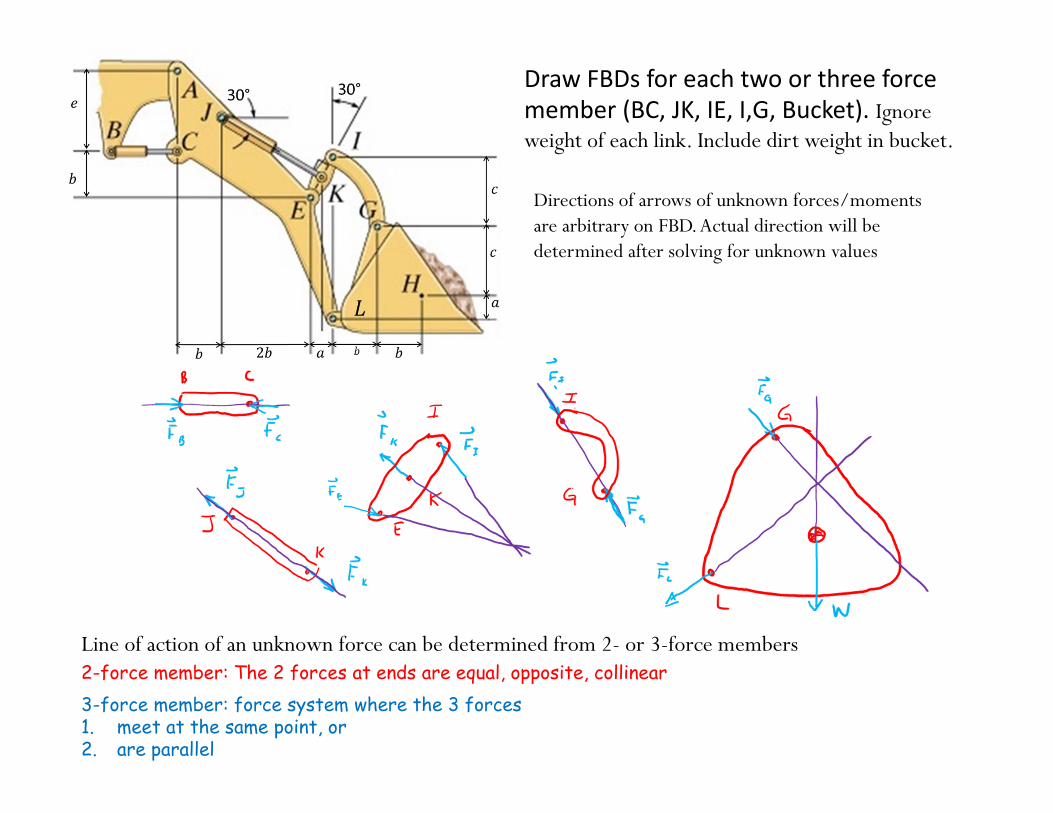
Draw FBDs for each two or three force member (BC, JK, IE, I,G, Bucket). Ignore weight of each link. Include dirt weight in bucket.
Directions of arrows of unknown forces/moments are arbitrary on FBD. Actual direction will be determined after solving for unknown values
Line of action of an unknown force can be determined from 2- or 3-force members2-force member: The 2 forces at ends are equal, opposite, collinear3-force member: force system where the 3 forces 1. meet at the same point, or2. are parallel
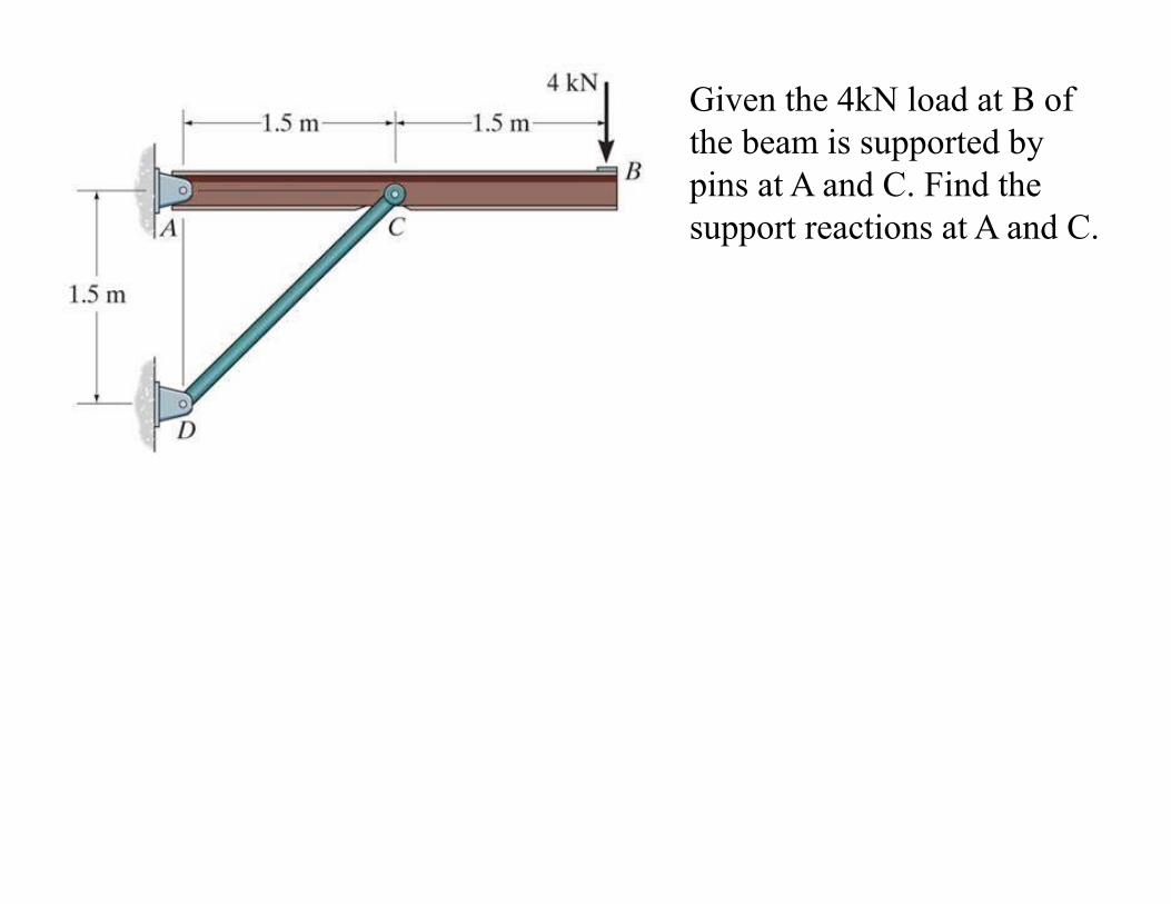
Given the 4kN load at B of the beam is supported by pins at A and C. Find the support reactions at A and C.
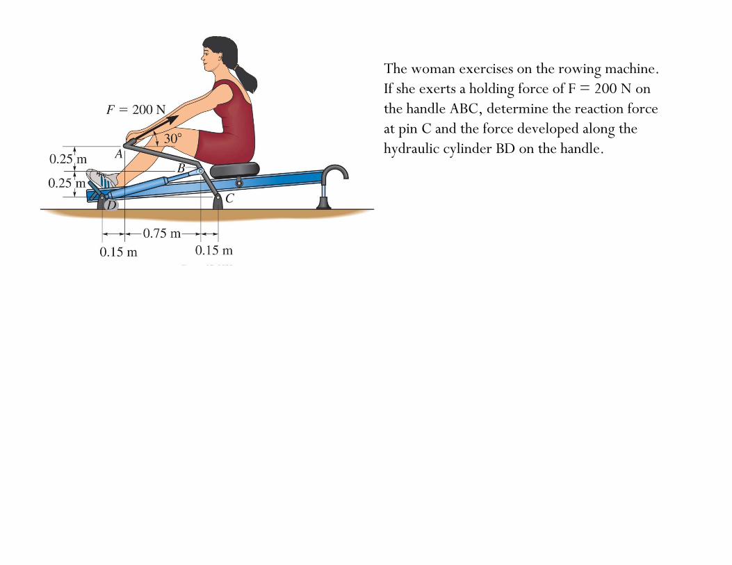
The woman exercises on the rowing machine. If she exerts a holding force of F = 200 N on the handle ABC, determine the reaction force at pin C and the force developed along the hydraulic cylinder BD on the handle.
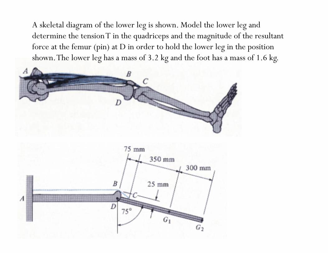
A skeletal diagram of the lower leg is shown. Model the lower leg and determine the tension T in the quadriceps and the magnitude of the resultant force at the femur (pin) at D in order to hold the lower leg in the position shown. The lower leg has a mass of 3.2 kg and the foot has a mass of 1.6 kg.
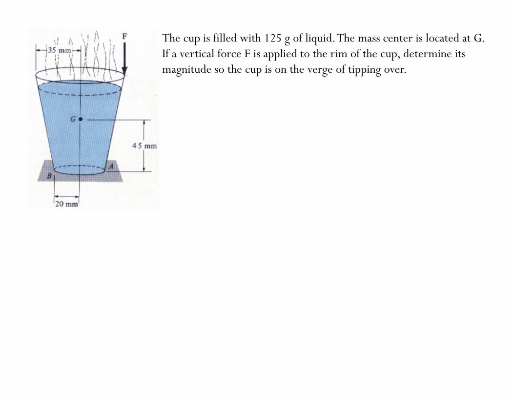
The cup is filled with 125 g of liquid. The mass center is located at G. If a vertical force F is applied to the rim of the cup, determine its magnitude so the cup is on the verge of tipping over.
Chapter 6: Structural Analysis
Goals and Objectives• Determine the forces in members of a truss using the method of
joints
• Determine zero-force members
• Determine the forces in members of a truss using the method of sections
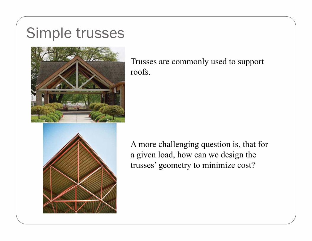
Simple trusses
Trusses are commonly used to support roofs.
A more challenging question is, that for a given load, how can we design the trusses’ geometry to minimize cost?
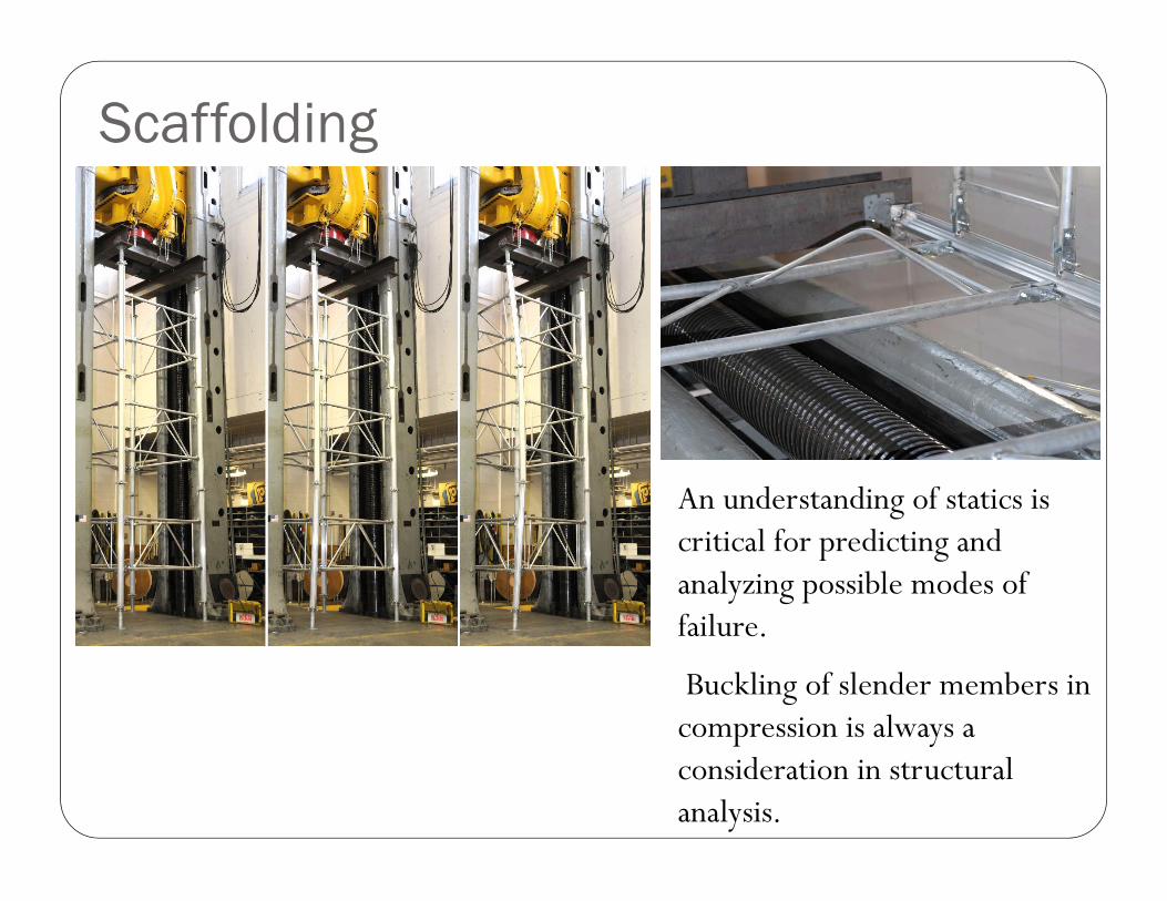
Scaffolding
An understanding of statics is critical for predicting and analyzing possible modes of failure.
Buckling of slender members in compression is always a consideration in structural analysis.
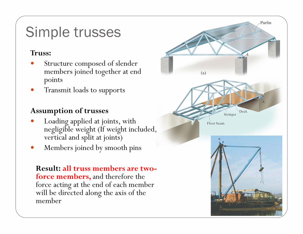
Truss: Structure composed of slender
members joined together at end points
Transmit loads to supports
Assumption of trusses Loading applied at joints, with
negligible weight (If weight included, vertical and split at joints)
Members joined by smooth pins
Result: all truss members are two-force members, and therefore the force acting at the end of each member will be directed along the axis of the member
Simple trusses
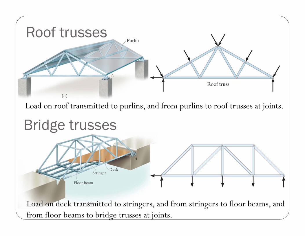
Roof trusses
Bridge trussesLoad on roof transmitted to purlins, and from purlins to roof trusses at joints.
Load on deck transmitted to stringers, and from stringers to floor beams, and from floor beams to bridge trusses at joints.
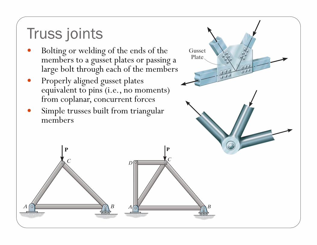
Truss joints Bolting or welding of the ends of the
members to a gusset plates or passing a large bolt through each of the members
Properly aligned gusset plates equivalent to pins (i.e., no moments) from coplanar, concurrent forces
Simple trusses built from triangular members
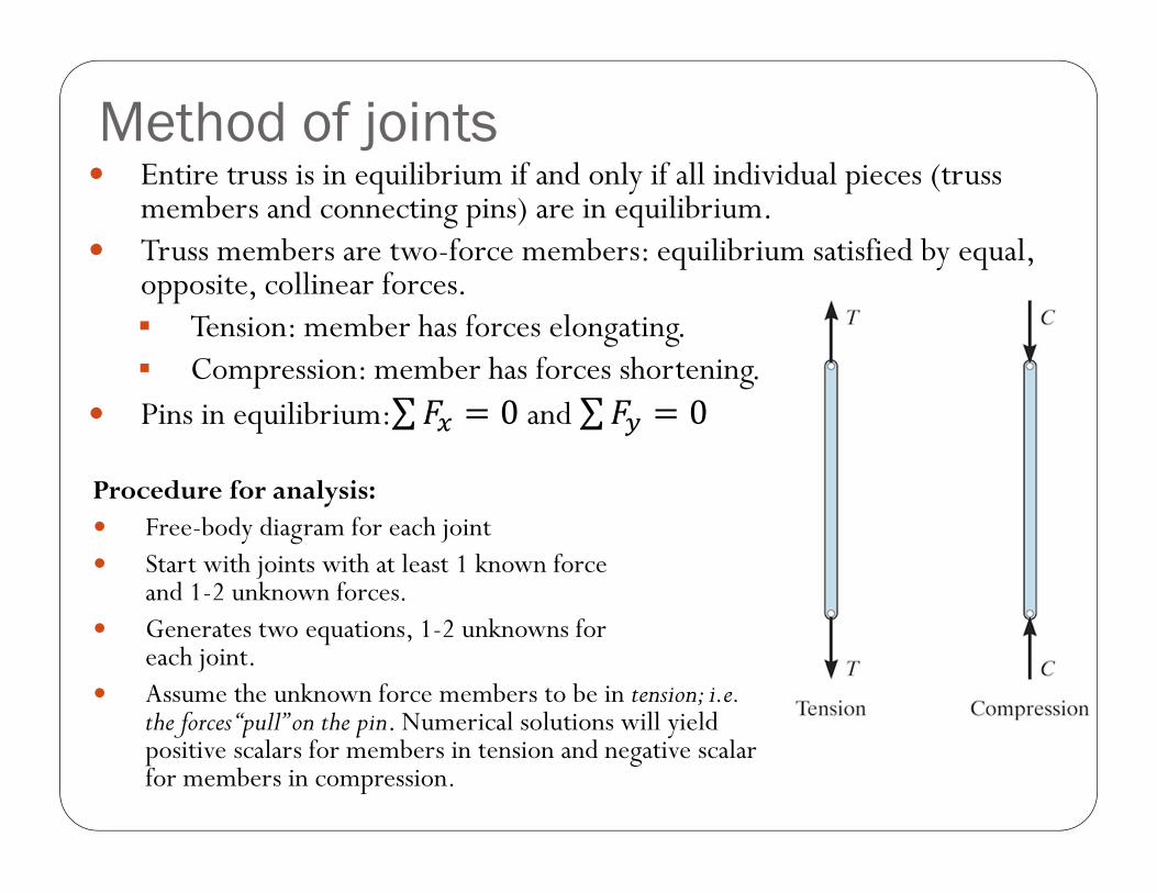
Method of joints Entire truss is in equilibrium if and only if all individual pieces (truss
members and connecting pins) are in equilibrium. Truss members are two-force members: equilibrium satisfied by equal,
opposite, collinear forces. Tension: member has forces elongating. Compression: member has forces shortening.
Pins in equilibrium:∑ 0and ∑ 0
Procedure for analysis: Free-body diagram for each joint Start with joints with at least 1 known force
and 1-2 unknown forces. Generates two equations, 1-2 unknowns for
each joint. Assume the unknown force members to be in tension; i.e.
the forces “pull” on the pin. Numerical solutions will yield positive scalars for members in tension and negative scalar for members in compression.
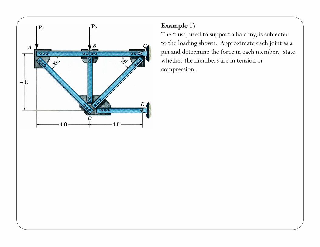
Example 1)The truss, used to support a balcony, is subjected to the loading shown. Approximate each joint as a pin and determine the force in each member. State whether the members are in tension or compression.
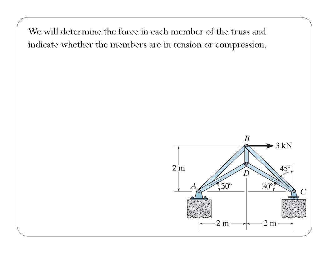
We will determine the force in each member of the truss and indicate whether the members are in tension or compression.
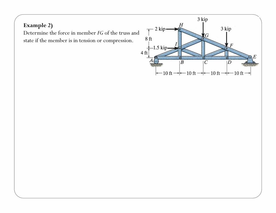
Example 2)Determine the force in member FG of the truss and state if the member is in tension or compression.
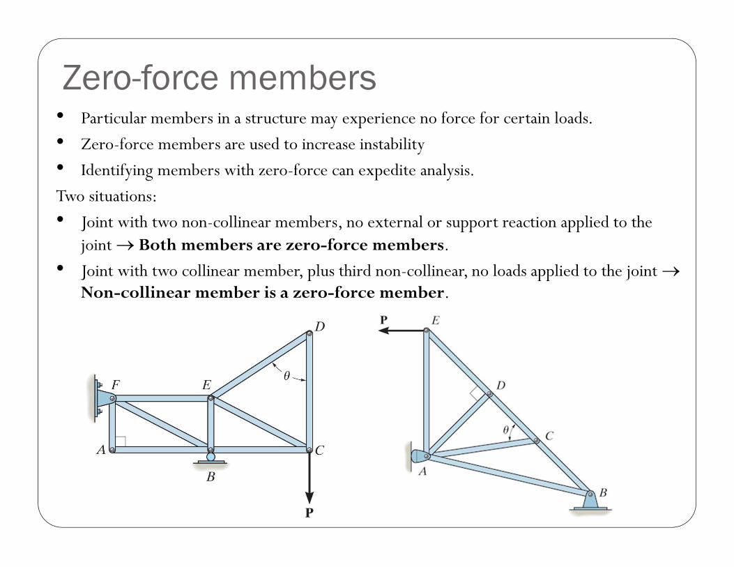
• Particular members in a structure may experience no force for certain loads.
• Zero-force members are used to increase instability
• Identifying members with zero-force can expedite analysis.
Two situations:
• Joint with two non-collinear members, no external or support reaction applied to the joint Both members are zero-force members.
• Joint with two collinear member, plus third non-collinear, no loads applied to the joint Non-collinear member is a zero-force member.
Zero-force members