Embed Size (px)
Citation preview
Equilibrium of Rigid Bodies
C H A P T E R
157
bee29400_ch04_156-217.indd Page 157 11/29/08 3:33:01 PM user-s172bee29400_ch04_156-217.indd Page 157 11/29/08 3:33:01 PM user-s172 /Volumes/204/MHDQ076/work%0/indd%0/Volumes/204/MHDQ076/work%0/indd%0
158
Chapter 4 Equilibrium of Rigid Bodies
4.1 Introduction 4.2 Free-Body Diagram 4.3 Reactions at Supports and
Connections for a Two-Dimensional Structure
4.4 Equilibrium of a Rigid Body in Two Dimensions
4.5 Statically Indeterminate Reactions. Partial Constraints
4.6 Equilibrium of a Two-Force Body 4.7 Equilibrium of a Three-Force
Body 4.8 Equilibrium of a Rigid Body in
Three Dimensions 4.9 Reactions at Supports and
Connections for a Three-Dimensional Structure
4.1 INTRODUCTIONWe saw in the preceding chapter that the external forces acting on a rigid body can be reduced to a force-couple system at some arbi-trary point O. When the force and the couple are both equal to zero, the external forces form a system equivalent to zero, and the rigid body is said to be in equilibrium. The necessary and sufficient conditions for the equilibrium of a rigid body, therefore, can be obtained by setting R and MR
O equal to zero in the relations (3.52) of Sec. 3.17:
oF 5 0 oMO 5 o(r 3 F) 5 0 (4.1)
Resolving each force and each moment into its rectangular components, we can express the necessary and sufficient conditions for the equilibrium of a rigid body with the following six scalar equations:
oFx 5 0 oFy 5 0 oFz 5 0 (4.2) oMx 5 0 oMy 5 0 oMz 5 0 (4.3)
The equations obtained can be used to determine unknown forces applied to the rigid body or unknown reactions exerted on it by its supports. We note that Eqs. (4.2) express the fact that the compo-nents of the external forces in the x, y, and z directions are balanced; Eqs. (4.3) express the fact that the moments of the external forces about the x, y, and z axes are balanced. Therefore, for a rigid body in equilibrium, the system of the external forces will impart no trans-lational or rotational motion to the body considered. In order to write the equations of equilibrium for a rigid body, it is essential to first identify all of the forces acting on that body and then to draw the corresponding free-body diagram. In this chapter we first consider the equilibrium of two-dimensional struc-tures subjected to forces contained in their planes and learn how to draw their free-body diagrams. In addition to the forces applied to a structure, the reactions exerted on the structure by its supports will be considered. A specific reaction will be associated with each type of support. You will learn how to determine whether the struc-ture is properly supported, so that you can know in advance whether the equations of equilibrium can be solved for the unknown forces and reactions. Later in the chapter, the equilibrium of three-dimensional structures will be considered, and the same kind of analysis will be given to these structures and their supports.
bee29400_ch04_156-217.indd Page 158 11/29/08 3:33:24 PM user-s172bee29400_ch04_156-217.indd Page 158 11/29/08 3:33:24 PM user-s172 /Volumes/204/MHDQ076/work%0/indd%0/Volumes/204/MHDQ076/work%0/indd%0
1594.2 FREE-BODY DIAGRAMIn solving a problem concerning the equilibrium of a rigid body, it is essential to consider all of the forces acting on the body; it is equally important to exclude any force which is not directly applied to the body. Omitting a force or adding an extraneous one would destroy the conditions of equilibrium. Therefore, the first step in the solution of the problem should be to draw a free-body diagram of the rigid body under consideration. Free-body diagrams have already been used on many occasions in Chap. 2. However, in view of their importance to the solution of equilibrium problems, we summarize here the various steps which must be followed in draw-ing a free-body diagram.
1. A clear decision should be made regarding the choice of the free body to be used. This body is then detached from the ground and is separated from all other bodies. The contour of the body thus isolated is sketched.
2. All external forces should be indicated on the free-body dia-gram. These forces represent the actions exerted on the free body by the ground and by the bodies which have been detached; they should be applied at the various points where the free body was supported by the ground or was connected to the other bodies. The weight of the free body should also be included among the external forces, since it represents the attraction exerted by the earth on the various particles forming the free body. As will be seen in Chap. 5, the weight should be applied at the center of gravity of the body. When the free body is made of several parts, the forces the various parts exert on each other should not be included among the external forces. These forces are internal forces as far as the free body is concerned.
3. The magnitudes and directions of the known external forces should be clearly marked on the free-body diagram. When indi-cating the directions of these forces, it must be remembered that the forces shown on the free-body diagram must be those which are exerted on, and not by, the free body. Known exter-nal forces generally include the weight of the free body and forces applied for a given purpose.
4. Unknown external forces usually consist of the reactions, through which the ground and other bodies oppose a possible motion of the free body. The reactions constrain the free body to remain in the same position, and, for that reason, are some-times called constraining forces. Reactions are exerted at the points where the free body is supported by or connected to other bodies and should be clearly indicated. Reactions are dis-cussed in detail in Secs. 4.3 and 4.8.
5. The free-body diagram should also include dimensions, since these may be needed in the computation of moments of forces. Any other detail, however, should be omitted.
4.2 Free-Body Diagram
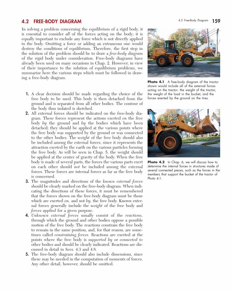
Photo 4.1 A free-body diagram of the tractor shown would include all of the external forces acting on the tractor: the weight of the tractor, the weight of the load in the bucket, and the forces exerted by the ground on the tires.
Photo 4.2 In Chap. 6, we will discuss how to determine the internal forces in structures made of several connected pieces, such as the forces in the members that support the bucket of the tractor of Photo 4.1.
bee29400_ch04_156-217.indd Page 159 11/29/08 3:33:25 PM user-s172bee29400_ch04_156-217.indd Page 159 11/29/08 3:33:25 PM user-s172 /Volumes/204/MHDQ076/work%0/indd%0/Volumes/204/MHDQ076/work%0/indd%0
160 Equilibrium of Rigid BodiesEQUILIBRIUM IN TWO DIMENSIONS
4.3 REACTIONS AT SUPPORTS AND CONNECTIONS FOR A TWO-DIMENSIONAL STRUCTURE
In the first part of this chapter, the equilibrium of a two-dimensional structure is considered; i.e., it is assumed that the structure being analyzed and the forces applied to it are contained in the same plane. Clearly, the reactions needed to maintain the structure in the same position will also be contained in this plane. The reactions exerted on a two-dimensional structure can be divided into three groups corresponding to three types of supports, or connections:
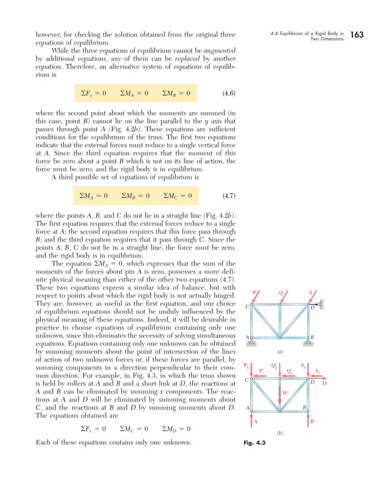
1. Reactions Equivalent to a Force with Known Line of Action. Supports and connections causing reactions of this type include rollers, rockers, frictionless surfaces, short links and cables, col-lars on frictionless rods, and frictionless pins in slots. Each of these supports and connections can prevent motion in one direction only. They are shown in Fig. 4.1, together with the reactions they produce. Each of these reactions involves one unknown, namely, the magnitude of the reaction; this magni-tude should be denoted by an appropriate letter. The line of action of the reaction is known and should be indicated clearly in the free-body diagram. The sense of the reaction must be as shown in Fig. 4.1 for the cases of a frictionless surface (toward the free body) or a cable (away from the free body). The reaction can be directed either way in the case of double-track rollers, links, collars on rods, and pins in slots. Single-track rollers and rockers are generally assumed to be reversible, and thus the corresponding reactions can also be directed either way.
2. Reactions Equivalent to a Force of Unknown Direction and Magnitude. Supports and connections causing reactions of this type include frictionless pins in fitted holes, hinges, and rough surfaces. They can prevent translation of the free body in all directions, but they cannot prevent the body from rotating about the connection. Reactions of this group involve two unknowns and are usually represented by their x and y com-ponents. In the case of a rough surface, the component normal to the surface must be directed away from the surface.
3. Reactions Equivalent to a Force and a Couple. These reactions are caused by fixed supports, which oppose any motion of the free body and thus constrain it completely. Fixed supports actu-ally produce forces over the entire surface of contact; these forces, however, form a system which can be reduced to a force and a couple. Reactions of this group involve three unknowns, consisting usually of the two components of the force and the moment of the couple.
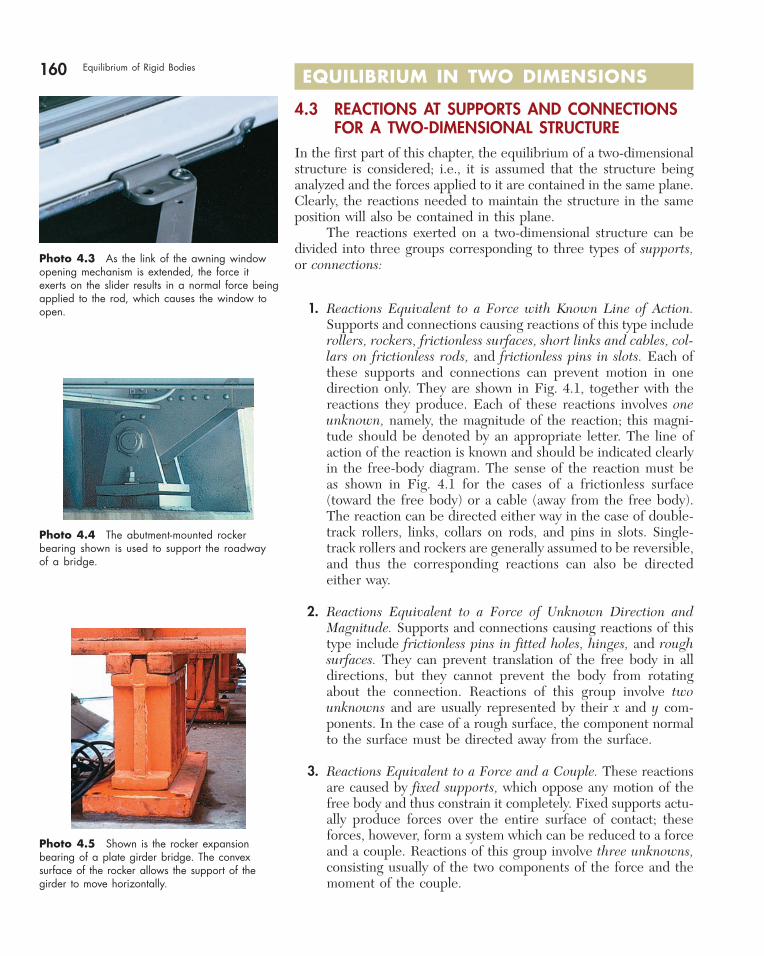
Photo 4.3 As the link of the awning window opening mechanism is extended, the force it exerts on the slider results in a normal force being applied to the rod, which causes the window to open.
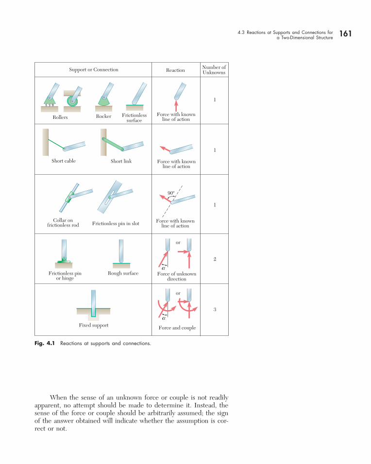
Photo 4.4 The abutment-mounted rocker bearing shown is used to support the roadway of a bridge.
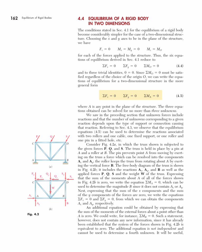
Photo 4.5 Shown is the rocker expansion bearing of a plate girder bridge. The convex surface of the rocker allows the support of the girder to move horizontally.
bee29400_ch04_156-217.indd Page 160 12/1/08 3:11:08 PM user-s172bee29400_ch04_156-217.indd Page 160 12/1/08 3:11:08 PM user-s172 /Volumes/204/MHDQ076/work%0/indd%0/Volumes/204/MHDQ076/work%0/indd%0
161
When the sense of an unknown force or couple is not readily apparent, no attempt should be made to determine it. Instead, the sense of the force or couple should be arbitrarily assumed; the sign of the answer obtained will indicate whether the assumption is cor-rect or not.
4.3 Reactions at Supports and Connections for a Two-Dimensional Structure
Fig. 4.1 Reactions at supports and connections.
Support or Connection Reaction Number ofUnknowns
Rollers Rocker Frictionlesssurface
Force with knownline of action
Force with knownline of action
Force with knownline of action
1
1
1
Short cable Short link
Collar onfrictionless rod Frictionless pin in slot
90º
Frictionless pinor hinge
Rough surface Force of unknowndirection
or
or
2
Fixed support Force and couple
3
a
a
bee29400_ch04_156-217.indd Page 161 11/29/08 3:33:27 PM user-s172bee29400_ch04_156-217.indd Page 161 11/29/08 3:33:27 PM user-s172 /Volumes/204/MHDQ076/work%0/indd%0/Volumes/204/MHDQ076/work%0/indd%0
162 Equilibrium of Rigid Bodies 4.4 EQUILIBRIUM OF A RIGID BODY IN TWO DIMENSIONS
The conditions stated in Sec. 4.1 for the equilibrium of a rigid body become considerably simpler for the case of a two-dimensional struc-ture. Choosing the x and y axes to be in the plane of the structure, we have
Fz 5 0 Mx 5 My 5 0 Mz 5 MO
for each of the forces applied to the structure. Thus, the six equa-tions of equilibrium derived in Sec. 4.1 reduce to
oFx 5 0 oFy 5 0 oMO 5 0 (4.4)
and to three trivial identities, 0 5 0. Since oMO 5 0 must be satis-fied regardless of the choice of the origin O, we can write the equa-tions of equilibrium for a two-dimensional structure in the more general form
oFx 5 0 oFy 5 0 oMA 5 0 (4.5)
where A is any point in the plane of the structure. The three equa-tions obtained can be solved for no more than three unknowns. We saw in the preceding section that unknown forces include reactions and that the number of unknowns corresponding to a given reaction depends upon the type of support or connection causing that reaction. Referring to Sec. 4.3, we observe that the equilibrium equations (4.5) can be used to determine the reactions associated with two rollers and one cable, one fixed support, or one roller and one pin in a fitted hole, etc. Consider Fig. 4.2a, in which the truss shown is subjected to the given forces P, Q, and S. The truss is held in place by a pin at A and a roller at B. The pin prevents point A from moving by exert-ing on the truss a force which can be resolved into the components Ax and Ay; the roller keeps the truss from rotating about A by exert-ing the vertical force B. The free-body diagram of the truss is shown in Fig. 4.2b; it includes the reactions Ax, Ay, and B as well as the applied forces P, Q, S and the weight W of the truss. Expressing that the sum of the moments about A of all of the forces shown in Fig. 4.2b is zero, we write the equation oMA 5 0, which can be used to determine the magnitude B since it does not contain Ax or Ay. Next, expressing that the sum of the x components and the sum of the y components of the forces are zero, we write the equations oFx 5 0 and oFy 5 0, from which we can obtain the components Ax and Ay, respectively. An additional equation could be obtained by expressing that the sum of the moments of the external forces about a point other than A is zero. We could write, for instance, oMB 5 0. Such a statement, however, does not contain any new information, since it has already been established that the system of the forces shown in Fig. 4.2b is equivalent to zero. The additional equation is not independent and cannot be used to determine a fourth unknown. It will be useful,
Fig. 4.2
C
A B
D
P Q S
(a)
C
A B
D
(b)
Py Qy Qx
SySx
W
Px
B
Ax
Ay
bee29400_ch04_156-217.indd Page 162 11/29/08 3:33:27 PM user-s172bee29400_ch04_156-217.indd Page 162 11/29/08 3:33:27 PM user-s172 /Volumes/204/MHDQ076/work%0/indd%0/Volumes/204/MHDQ076/work%0/indd%0
163however, for checking the solution obtained from the original three equations of equilibrium. While the three equations of equilibrium cannot be augmented by additional equations, any of them can be replaced by another equation. Therefore, an alternative system of equations of equilib-rium is
oFx 5 0 oMA 5 0 oMB 5 0 (4.6)
where the second point about which the moments are summed (in this case, point B) cannot lie on the line parallel to the y axis that passes through point A (Fig. 4.2b). These equations are sufficient conditions for the equilibrium of the truss. The first two equations indicate that the external forces must reduce to a single vertical force at A. Since the third equation requires that the moment of this force be zero about a point B which is not on its line of action, the force must be zero, and the rigid body is in equilibrium. A third possible set of equations of equilibrium is
oMA 5 0 oMB 5 0 oMC 5 0 (4.7)
where the points A, B, and C do not lie in a straight line (Fig. 4.2b). The first equation requires that the external forces reduce to a single force at A; the second equation requires that this force pass through B; and the third equation requires that it pass through C. Since the points A, B, C do not lie in a straight line, the force must be zero, and the rigid body is in equilibrium. The equation oMA 5 0, which expresses that the sum of the moments of the forces about pin A is zero, possesses a more defi-nite physical meaning than either of the other two equations (4.7). These two equations express a similar idea of balance, but with respect to points about which the rigid body is not actually hinged. They are, however, as useful as the first equation, and our choice of equilibrium equations should not be unduly influenced by the physical meaning of these equations. Indeed, it will be desirable in practice to choose equations of equilibrium containing only one unknown, since this eliminates the necessity of solving simulta neous equations. Equations containing only one unknown can be obtained by summing moments about the point of intersection of the lines of action of two unknown forces or, if these forces are parallel, by summing components in a direction perpendicular to their com-mon direction. For example, in Fig. 4.3, in which the truss shown is held by rollers at A and B and a short link at D, the reactions at A and B can be eliminated by summing x components. The reac-tions at A and D will be eliminated by summing moments about C, and the reactions at B and D by summing moments about D. The equations obtained are
oFx 5 0 oMC 5 0 oMD 5 0
Each of these equations contains only one unknown. Fig. 4.3
C
A B
D
D
P Q S
(a)
C
A B
D
(b)
Py QyQx
SySx
A
W
Px
B
4.4 Equilibrium of a Rigid Body in Two Dimensions
bee29400_ch04_156-217.indd Page 163 11/29/08 3:33:28 PM user-s172bee29400_ch04_156-217.indd Page 163 11/29/08 3:33:28 PM user-s172 /Volumes/204/MHDQ076/work%0/indd%0/Volumes/204/MHDQ076/work%0/indd%0
164 Equilibrium of Rigid Bodies 4.5 STATICALLY INDETERMINATE REACTIONS. PARTIAL CONSTRAINTS
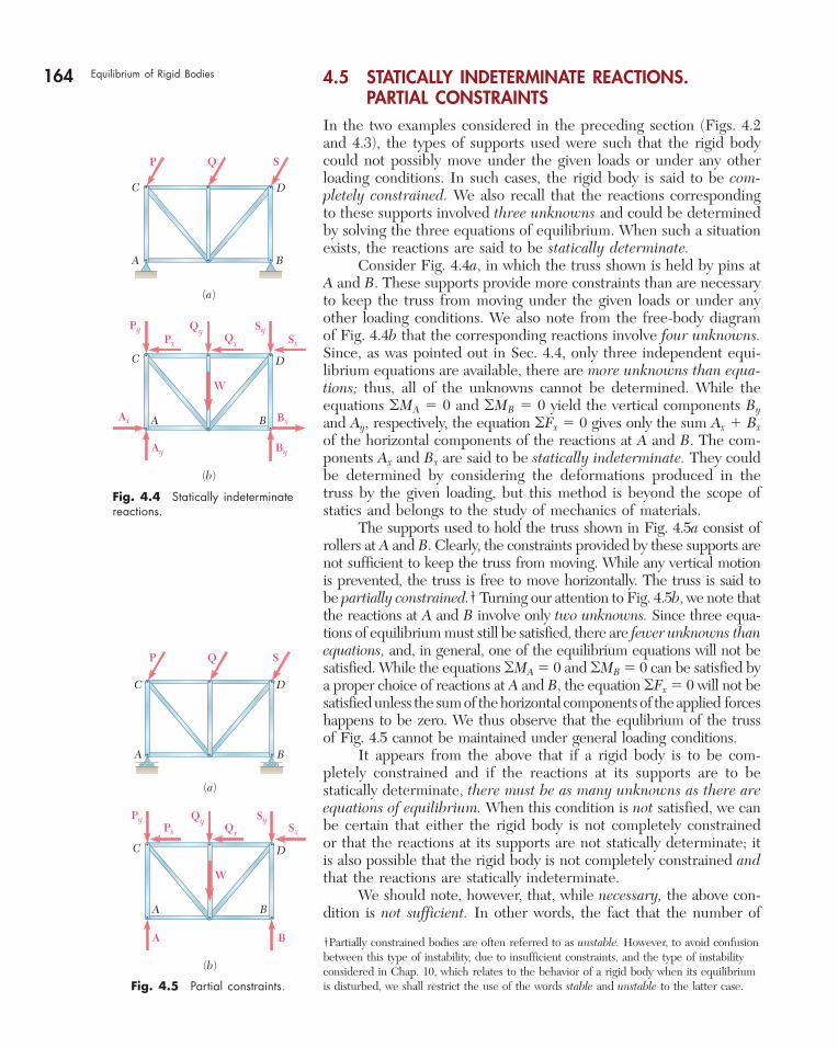
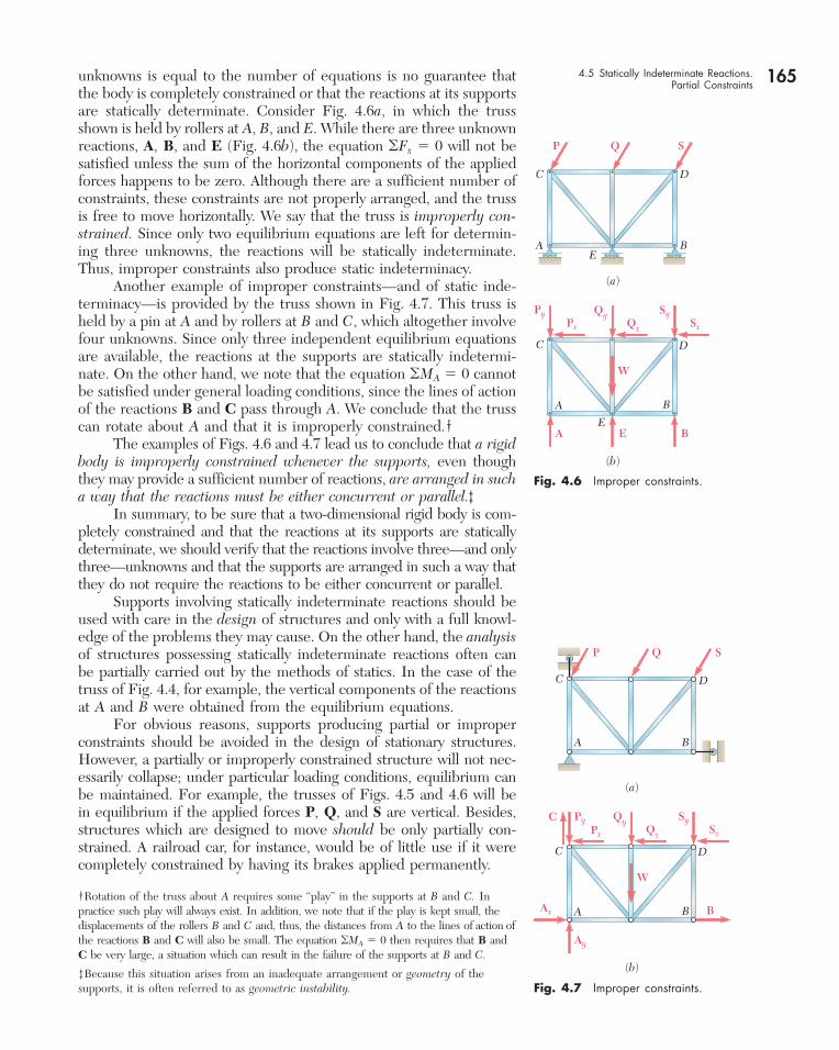
In the two examples considered in the preceding section (Figs. 4.2 and 4.3), the types of supports used were such that the rigid body could not possibly move under the given loads or under any other loading conditions. In such cases, the rigid body is said to be com-pletely constrained. We also recall that the reactions corresponding to these supports involved three unknowns and could be determined by solving the three equations of equilibrium. When such a situation exists, the reactions are said to be statically determinate. Consider Fig. 4.4a, in which the truss shown is held by pins at A and B. These supports provide more constraints than are necessary to keep the truss from moving under the given loads or under any other loading conditions. We also note from the free-body diagram of Fig. 4.4b that the corresponding reactions involve four unknowns. Since, as was pointed out in Sec. 4.4, only three independent equi-librium equations are available, there are more unknowns than equa-tions; thus, all of the unknowns cannot be determined. While the equations oMA 5 0 and oMB 5 0 yield the vertical components By and Ay, respectively, the equation oFx 5 0 gives only the sum Ax 1 Bx of the horizontal components of the reactions at A and B. The com-ponents Ax and Bx are said to be statically indeterminate. They could be determined by considering the deformations produced in the truss by the given loading, but this method is beyond the scope of statics and belongs to the study of mechanics of materials. The supports used to hold the truss shown in Fig. 4.5a consist of rollers at A and B. Clearly, the constraints provided by these supports are not sufficient to keep the truss from moving. While any vertical motion is prevented, the truss is free to move horizontally. The truss is said to be partially constrained.† Turning our attention to Fig. 4.5b, we note that the reactions at A and B involve only two unknowns. Since three equa-tions of equilibrium must still be satisfied, there are fewer unknowns than equations, and, in general, one of the equilibrium equations will not be satisfied. While the equations oMA 5 0 and oMB 5 0 can be satisfied by a proper choice of reactions at A and B, the equation oFx 5 0 will not be satisfied unless the sum of the horizontal components of the applied forces happens to be zero. We thus observe that the equlibrium of the truss of Fig. 4.5 cannot be maintained under general loading conditions. It appears from the above that if a rigid body is to be com-pletely constrained and if the reactions at its supports are to be statically determinate, there must be as many unknowns as there are equations of equilibrium. When this condition is not satisfied, we can be certain that either the rigid body is not completely constrained or that the reactions at its supports are not statically determinate; it is also possible that the rigid body is not completely constrained and that the reactions are statically indeterminate. We should note, however, that, while necessary, the above con-dition is not sufficient. In other words, the fact that the number of
Fig. 4.4 Statically indeterminate reactions.
C
A B
D
P Q S
(a)
C
A B
D
(b)
Py QyQx
SySx
Bx
By
Ax
Ay
W
Px
Fig. 4.5 Partial constraints.
C
A B
D
P Q S
(a)
C
A B
D
(b)
Py QyQx
SySx
A
W
Px
B †Partially constrained bodies are often referred to as unstable. However, to avoid confusion between this type of instability, due to insufficient constraints, and the type of instability considered in Chap. 10, which relates to the behavior of a rigid body when its equilibrium is disturbed, we shall restrict the use of the words stable and unstable to the latter case.
bee29400_ch04_156-217.indd Page 164 11/29/08 3:33:28 PM user-s172bee29400_ch04_156-217.indd Page 164 11/29/08 3:33:28 PM user-s172 /Volumes/204/MHDQ076/work%0/indd%0/Volumes/204/MHDQ076/work%0/indd%0
165unknowns is equal to the number of equations is no guarantee that the body is completely constrained or that the reactions at its supports are statically determinate. Consider Fig. 4.6a, in which the truss shown is held by rollers at A, B, and E. While there are three unknown reactions, A, B, and E (Fig. 4.6b), the equation oFx 5 0 will not be satisfied unless the sum of the horizontal components of the applied forces happens to be zero. Although there are a sufficient number of constraints, these constraints are not properly arranged, and the truss is free to move horizontally. We say that the truss is improperly con-strained. Since only two equilibrium equations are left for determin-ing three unknowns, the reactions will be statically indeterminate. Thus, improper constraints also produce static indeterminacy. Another example of improper constraints—and of static inde-terminacy—is provided by the truss shown in Fig. 4.7. This truss is held by a pin at A and by rollers at B and C, which altogether involve four unknowns. Since only three independent equilibrium equations are available, the reactions at the supports are statically indetermi-nate. On the other hand, we note that the equation oMA 5 0 cannot be satisfied under general loading conditions, since the lines of action of the reactions B and C pass through A. We conclude that the truss can rotate about A and that it is improperly constrained.† The examples of Figs. 4.6 and 4.7 lead us to conclude that a rigid body is improperly constrained whenever the supports, even though they may provide a sufficient number of reactions, are arranged in such a way that the reactions must be either concurrent or parallel.‡ In summary, to be sure that a two-dimensional rigid body is com-pletely constrained and that the reactions at its supports are statically determinate, we should verify that the reactions involve three—and only three—unknowns and that the supports are arranged in such a way that they do not require the reactions to be either concurrent or parallel. Supports involving statically indeterminate reactions should be used with care in the design of structures and only with a full knowl-edge of the problems they may cause. On the other hand, the analysis of structures possessing statically indeterminate reactions often can be partially carried out by the methods of statics. In the case of the truss of Fig. 4.4, for example, the vertical components of the reactions at A and B were obtained from the equilibrium equations. For obvious reasons, supports producing partial or improper constraints should be avoided in the design of stationary structures. However, a partially or improperly constrained structure will not nec-essarily collapse; under particular loading conditions, equilibrium can be maintained. For example, the trusses of Figs. 4.5 and 4.6 will be in equilibrium if the applied forces P, Q, and S are vertical. Besides, structures which are designed to move should be only partially con-strained. A railroad car, for instance, would be of little use if it were completely constrained by having its brakes applied permanently.
C
A BE
E
D
P Q S
(a)
C
A B
D
(b)
Py QyQx
SySx
A
W
Px
BE
Fig. 4.6 Improper constraints.
Fig. 4.7 Improper constraints.
B
C
Ax
C D
P Q S
(a)
C
A B
A B
D
(b)
Py QyQx
SySx
Ay
W
Px
4.5 Statically Indeterminate Reactions. Partial Constraints
†Rotation of the truss about A requires some “play” in the supports at B and C. In practice such play will always exist. In addition, we note that if the play is kept small, the displacements of the rollers B and C and, thus, the distances from A to the lines of action of the reactions B and C will also be small. The equation oMA 5 0 then requires that B and C be very large, a situation which can result in the failure of the supports at B and C.
‡Because this situation arises from an inadequate arrangement or geometry of the supports, it is often referred to as geometric instability.
bee29400_ch04_156-217.indd Page 165 11/29/08 3:33:29 PM user-s172bee29400_ch04_156-217.indd Page 165 11/29/08 3:33:29 PM user-s172 /Volumes/204/MHDQ076/work%0/indd%0/Volumes/204/MHDQ076/work%0/indd%0
SOLUTION
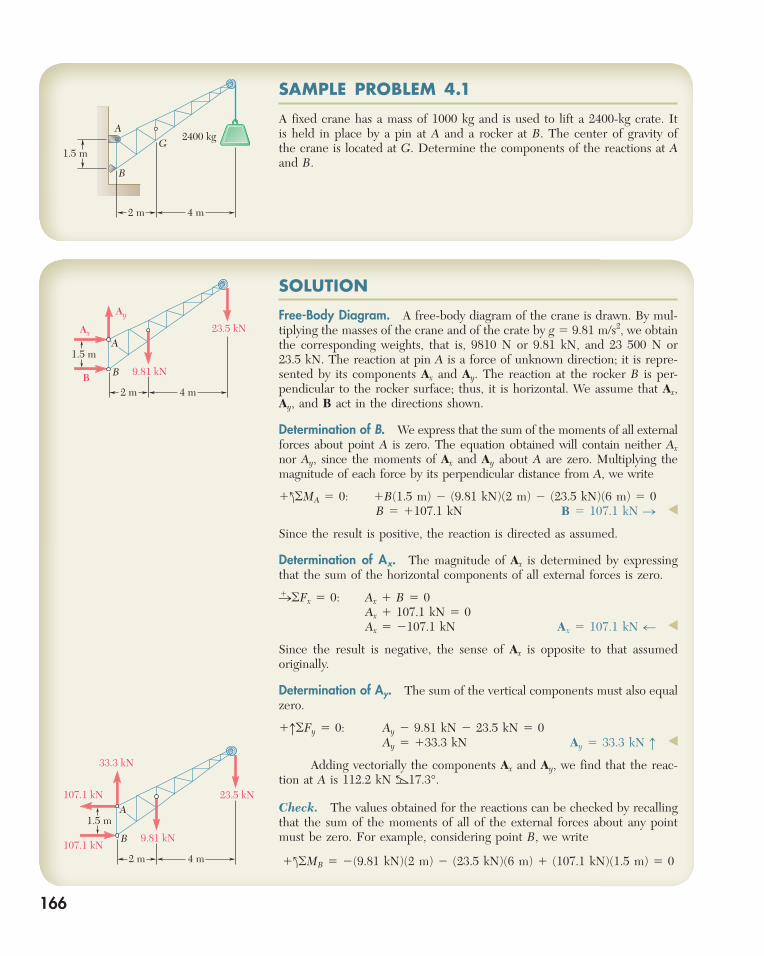
Free-Body Diagram. A free-body diagram of the crane is drawn. By mul-tiplying the masses of the crane and of the crate by g 5 9.81 m/s2, we obtain the corresponding weights, that is, 9810 N or 9.81 kN, and 23 500 N or 23.5 kN. The reaction at pin A is a force of unknown direction; it is repre-sented by its components Ax and Ay. The reaction at the rocker B is per-pendicular to the rocker surface; thus, it is horizontal. We assume that Ax, Ay, and B act in the directions shown.
Determination of B. We express that the sum of the moments of all external forces about point A is zero. The equation obtained will contain neither Ax nor Ay, since the moments of Ax and Ay about A are zero. Multiplying the magnitude of each force by its perpendicular distance from A, we write
1loMA 5 0: 1B(1.5 m) 2 (9.81 kN)(2 m) 2 (23.5 kN)(6 m) 5 0 B 5 1107.1 kN B 5 107.1 kN n ◀
Since the result is positive, the reaction is directed as assumed.
Determination of Ax. The magnitude of Ax is determined by expressing that the sum of the horizontal components of all external forces is zero.
n1 oFx 5 0: Ax 1 B 5 0 Ax 1 107.1 kN 5 0 Ax 5 2107.1 kN Ax 5 107.1 kN m ◀
Since the result is negative, the sense of Ax is opposite to that assumed originally.
Determination of Ay. The sum of the vertical components must also equal zero.
1hoFy 5 0: Ay 2 9.81 kN 2 23.5 kN 5 0 Ay 5 133.3 kN Ay 5 33.3 kN h ◀
Adding vectorially the components Ax and Ay, we find that the reac-tion at A is 112.2 kN b17.3°.
Check. The values obtained for the reactions can be checked by recalling that the sum of the moments of all of the external forces about any point must be zero. For example, considering point B, we write
1loMB 5 2(9.81 kN)(2 m) 2 (23.5 kN)(6 m) 1 (107.1 kN)(1.5 m) 5 0
SAMPLE PROBLEM 4.1
A fixed crane has a mass of 1000 kg and is used to lift a 2400-kg crate. It is held in place by a pin at A and a rocker at B. The center of gravity of the crane is located at G. Determine the components of the reactions at A and B.
2400 kgA
B
G
4 m2 m
1.5 m
A
BB
23.5 kN
Ay
Ax
9.81 kN
1.5 m
4 m2 m
33.3 kN
107.1 kN
107.1 kN
A
B
23.5 kN
9.81 kN
4 m2 m
1.5 m
166
bee29400_ch04_156-217.indd Page 166 11/29/08 3:33:29 PM user-s172bee29400_ch04_156-217.indd Page 166 11/29/08 3:33:29 PM user-s172 /Volumes/204/MHDQ076/work%0/indd%0/Volumes/204/MHDQ076/work%0/indd%0
167
SOLUTION
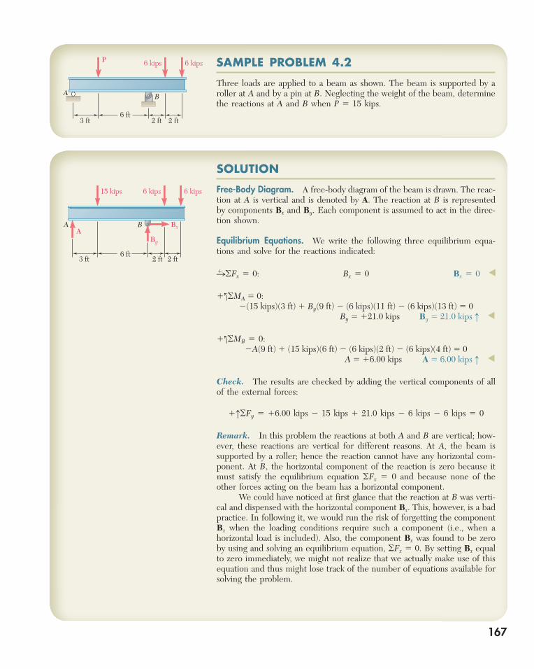
Free-Body Diagram. A free-body diagram of the beam is drawn. The reac-tion at A is vertical and is denoted by A. The reaction at B is represented by components Bx and By. Each component is assumed to act in the direc-tion shown.
Equilibrium Equations. We write the following three equilibrium equa-tions and solve for the reactions indicated:
n1 oFx 5 0: Bx 5 0 Bx 5 0 ◀
1loMA 5 0:2(15 kips)(3 ft) 1 By(9 ft) 2 (6 kips)(11 ft) 2 (6 kips)(13 ft) 5 0
By 5 121.0 kips By 5 21.0 kips h ◀
1loMB 5 0:2A(9 ft) 1 (15 kips)(6 ft) 2 (6 kips)(2 ft) 2 (6 kips)(4 ft) 5 0
A 5 16.00 kips A 5 6.00 kips h ◀
Check. The results are checked by adding the vertical components of all of the external forces:
1hoFy 5 16.00 kips 2 15 kips 1 21.0 kips 2 6 kips 2 6 kips 5 0
Remark. In this problem the reactions at both A and B are vertical; how-ever, these reactions are vertical for different reasons. At A, the beam is supported by a roller; hence the reaction cannot have any horizontal com-ponent. At B, the horizontal component of the reaction is zero because it must satisfy the equilibrium equation oFx 5 0 and because none of the other forces acting on the beam has a horizontal component. We could have noticed at first glance that the reaction at B was verti-cal and dispensed with the horizontal component Bx. This, however, is a bad practice. In following it, we would run the risk of forgetting the component Bx when the loading conditions require such a component (i.e., when a horizontal load is included). Also, the component Bx was found to be zero by using and solving an equilibrium equation, oFx 5 0. By setting Bx equal to zero immediately, we might not realize that we actually make use of this equation and thus might lose track of the number of equations available for solving the problem.
SAMPLE PROBLEM 4.2
Three loads are applied to a beam as shown. The beam is supported by a roller at A and by a pin at B. Neglecting the weight of the beam, determine the reactions at A and B when P 5 15 kips.
3 ft 2 ft 2 ft
6 kips 6 kipsP
6 ft
A B
3 ft 2 ft 2 ft
6 kips15 kips 6 kips
6 ft
By
BxAA
B
bee29400_ch04_156-217.indd Page 167 11/29/08 3:33:29 PM user-s172bee29400_ch04_156-217.indd Page 167 11/29/08 3:33:29 PM user-s172 /Volumes/204/MHDQ076/work%0/indd%0/Volumes/204/MHDQ076/work%0/indd%0
168
SOLUTION
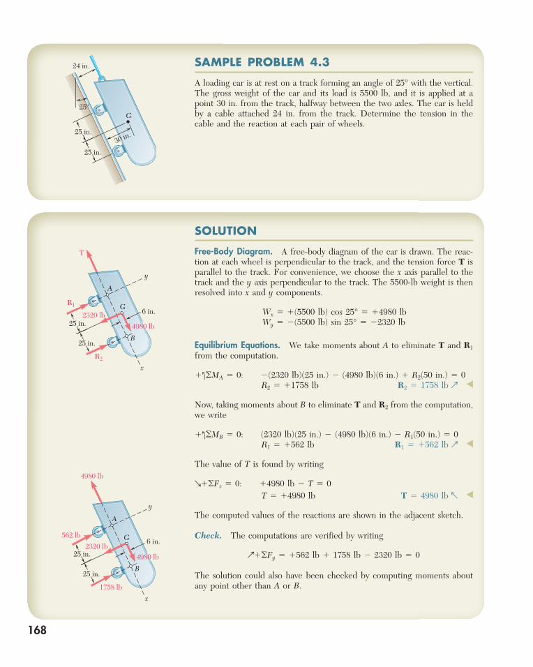
Free-Body Diagram. A free-body diagram of the car is drawn. The reac-tion at each wheel is perpendicular to the track, and the tension force T is parallel to the track. For convenience, we choose the x axis parallel to the track and the y axis perpendicular to the track. The 5500-lb weight is then resolved into x and y components.
Wx 5 1(5500 lb) cos 25° 5 14980 lbWy 5 2(5500 lb) sin 25° 5 22320 lb
Equilibrium Equations. We take moments about A to eliminate T and R1 from the computation.
1loMA 5 0: 2(2320 lb)(25 in.) 2 (4980 lb)(6 in.) 1 R2(50 in.) 5 0 R2 5 11758 lb R2 5 1758 lb p ◀
Now, taking moments about B to eliminate T and R2 from the computation, we write
1loMB 5 0: (2320 lb)(25 in.) 2 (4980 lb)(6 in.) 2 R1(50 in.) 5 0 R1 5 1562 lb R1 5 1562 lb p ◀
The value of T is found by writing
q1oFx 5 0: 14980 lb 2 T 5 0 T 5 14980 lb T 5 4980 lb r ◀
The computed values of the reactions are shown in the adjacent sketch.
Check. The computations are verified by writing
p1oFy 5 1562 lb 1 1758 lb 2 2320 lb 5 0
The solution could also have been checked by computing moments about any point other than A or B.
SAMPLE PROBLEM 4.3
A loading car is at rest on a track forming an angle of 25° with the vertical. The gross weight of the car and its load is 5500 lb, and it is applied at a point 30 in. from the track, halfway between the two axles. The car is held by a cable attached 24 in. from the track. Determine the tension in the cable and the reaction at each pair of wheels.
24 in.
25ºG
25 in.
25 in.30 in.
y
x
R1
R2
2320 lb 6 in.
A
T
B
G
25 in.
25 in.
4980 lb
562 lb
1758 lb
y
x
4980 lb
25 in.
25 in.
2320 lb6 in.
A
B
G
4980 lb
bee29400_ch04_156-217.indd Page 168 11/29/08 3:33:30 PM user-s172bee29400_ch04_156-217.indd Page 168 11/29/08 3:33:30 PM user-s172 /Volumes/204/MHDQ076/work%0/indd%0/Volumes/204/MHDQ076/work%0/indd%0
169
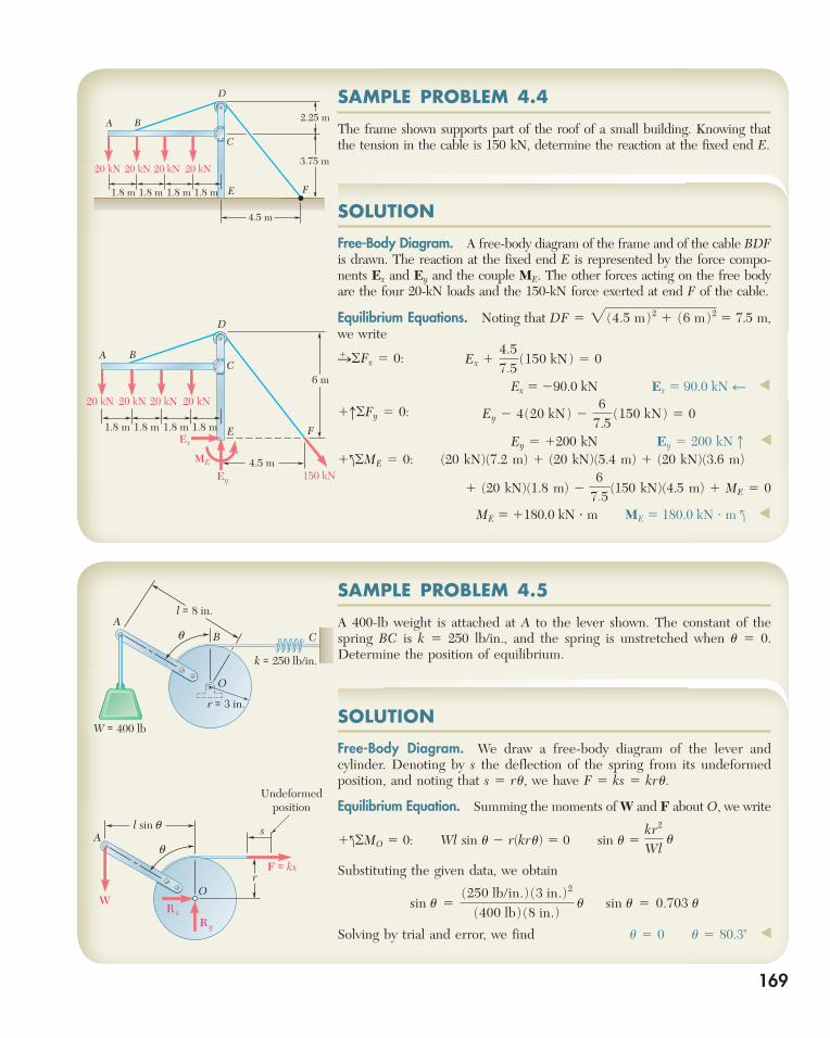
SAMPLE PROBLEM 4.4
The frame shown supports part of the roof of a small building. Knowing that the tension in the cable is 150 kN, determine the reaction at the fixed end E.
SOLUTION
Free-Body Diagram. A free-body diagram of the frame and of the cable BDF is drawn. The reaction at the fixed end E is represented by the force compo-nents Ex and Ey and the couple ME. The other forces acting on the free body are the four 20-kN loads and the 150-kN force exerted at end F of the cable.
Equilibrium Equations. Noting that DF 5 2 (4.5 m)2 1 (6 m)2 5 7.5 m, we write
n1 oFx 5 0: Ex 14.57.5
(150 kN) 5 0
Ex 5 290.0 kN Ex 5 90.0 kN z ◀
1hoFy 5 0: Ey 2 4(20 kN) 26
7.5(150 kN) 5 0
Ey 5 1200 kN Ey 5 200 kNx ◀
1loME 5 0: (20 kN)(7.2 m) 1 (20 kN)(5.4 m) 1 (20 kN)(3.6 m)
1 (20 kN)(1.8 m) 2 6
7.5(150 kN)(4.5 m) 1 ME 5 0
ME 5 1180.0 kN ? m ME 5 180.0 kN ? m l ◀
6 m
150 kNEy
Ex
ME
20 kN 20 kN 20 kN 20 kN
A BC
D
E F
4.5 m
1.8 m 1.8 m 1.8 m 1.8 m
20 kN 20 kN 20 kN 20 kN
A B
C
D
E F1.8 m 1.8 m 1.8 m 1.8 m
2.25 m
3.75 m
4.5 m
SAMPLE PROBLEM 4.5
A 400-lb weight is attached at A to the lever shown. The constant of the spring BC is k 5 250 lb/in., and the spring is unstretched when u 5 0. Determine the position of equilibrium.
As
OW
F = ks
Ry
R x
Undeformedposition
q
r
l sin q
SOLUTION
Free-Body Diagram. We draw a free-body diagram of the lever and cylinder. Denoting by s the deflection of the spring from its undeformed position, and noting that s 5 ru, we have F 5 ks 5 kru.
Equilibrium Equation. Summing the moments of W and F about O, we write
1loMO 5 0: Wl sin u 2 r(kru) 5 0 sin u 5 kr2
Wl u
Substituting the given data, we obtain
sin u 5(250 lb/in.) (3 in.)2
(400 lb) (8 in.) u sin u 5 0.703 u
Solving by trial and error, we find u 5 0 u 5 80.3˚ ◀
AB C
O
k = 250 lb/in.
r = 3 in.
l = 8 in.
W = 400 lb
q
bee29400_ch04_156-217.indd Page 169 11/29/08 3:33:30 PM user-s172bee29400_ch04_156-217.indd Page 169 11/29/08 3:33:30 PM user-s172 /Volumes/204/MHDQ076/work%0/indd%0/Volumes/204/MHDQ076/work%0/indd%0
170
You saw that the external forces acting on a rigid body in equilibrium form a system equivalent to zero. To solve an equilibrium problem your first task is
to draw a neat, reasonably large free-body diagram on which you will show all external forces. Both known and unknown forces must be included.
For a two-dimensional rigid body, the reactions at the supports can involve one, two, or three unknowns depending on the type of support (Fig. 4.1). For the suc-cessful solution of a problem, a correct free-body diagram is essential. Never pro-ceed with the solution of a problem until you are sure that your free-body diagram includes all loads, all reactions, and the weight of the body (if appropriate).
1. You can write three equilibrium equations and solve them for three unknowns.The three equations might be
oFx 5 0 oFy 5 0 oMO 5 0
However, there are usually several sets of equations that you can write, such as
oFx 5 0 oMA 5 0 oMB 5 0
where point B is chosen in such a way that the line AB is not parallel to the y axis, or
oMA 5 0 oMB 5 0 oMC 5 0
where the points A, B, and C do not lie in a straight line.
2. To simplify your solution, it may be helpful to use one of the following solu-tion techniques if applicable. a. By summing moments about the point of intersection of the lines of action of two unknown forces, you will obtain an equation in a single unknown. b. By summing components in a direction perpendicular to two unknown parallel forces, you will obtain an equation in a single unknown.
3. After drawing your free-body diagram, you may find that one of the fol-lowing special situations exists. a. The reactions involve fewer than three unknowns; the body is said to be partially constrained and motion of the body is possible. b. The reactions involve more than three unknowns; the reactions are said to be statically indeterminate. While you may be able to calculate one or two reactions, you cannot determine all of the reactions. c. The reactions pass through a single point or are parallel; the body is said to be improperly constrained and motion can occur under a general loading condition.
SOLVING PROBLEMSON YOUR OWN
bee29400_ch04_156-217.indd Page 170 11/29/08 3:33:31 PM user-s172bee29400_ch04_156-217.indd Page 170 11/29/08 3:33:31 PM user-s172 /Volumes/204/MHDQ076/work%0/indd%0/Volumes/204/MHDQ076/work%0/indd%0
PROBLEMS
171
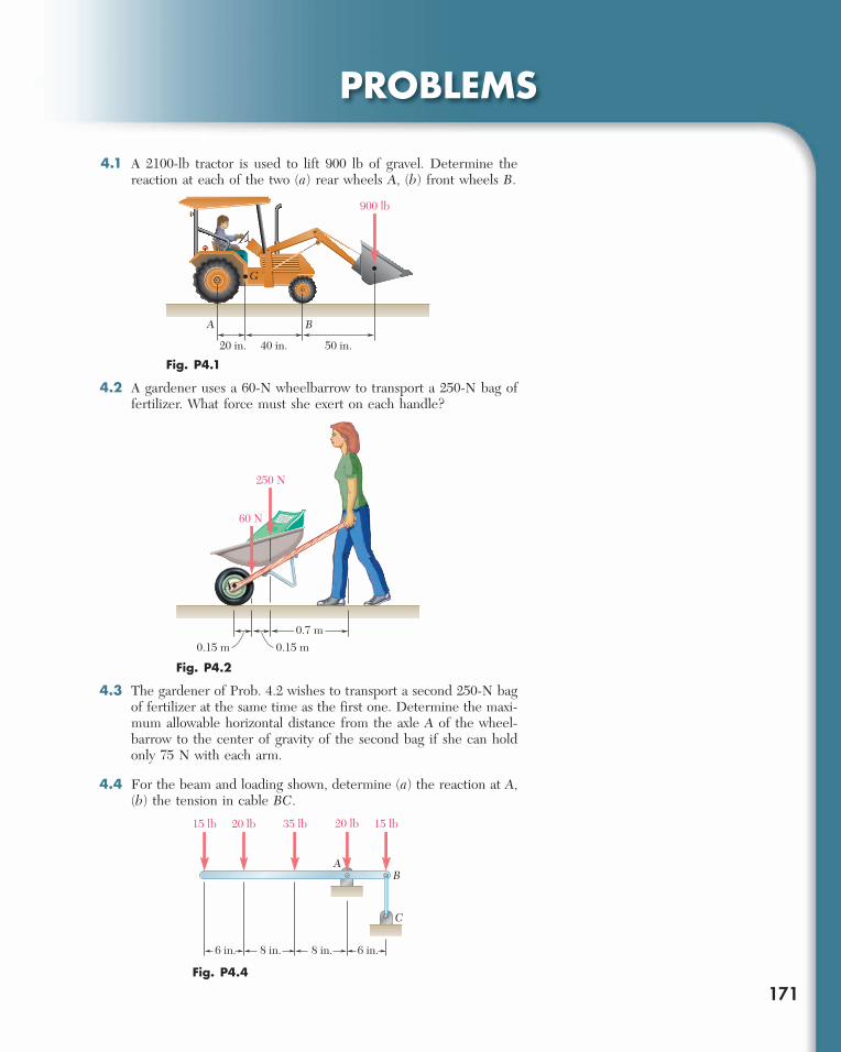
4.1 A 2100-lb tractor is used to lift 900 lb of gravel. Determine the reaction at each of the two (a) rear wheels A, (b) front wheels B.
20 in. 40 in. 50 in.
900 lb
A B
G
Fig. P4.1
0.15 m 0.15 m
60 N
250 N
A
0.7 m
Fig. P4.2
A
C
B
15 lb 20 lb 35 lb 15 lb20 lb
6 in. 8 in. 8 in. 6 in.
Fig. P4.4
4.2 A gardener uses a 60-N wheelbarrow to transport a 250-N bag of fertilizer. What force must she exert on each handle?
4.3 The gardener of Prob. 4.2 wishes to transport a second 250-N bag of fertilizer at the same time as the first one. Determine the maxi-mum allowable horizontal distance from the axle A of the wheel-barrow to the center of gravity of the second bag if she can hold only 75 N with each arm.
4.4 For the beam and loading shown, determine (a) the reaction at A, (b) the tension in cable BC.
bee29400_ch04_156-217.indd Page 171 11/29/08 3:33:40 PM user-s172bee29400_ch04_156-217.indd Page 171 11/29/08 3:33:40 PM user-s172 /Volumes/204/MHDQ076/work%0/indd%0/Volumes/204/MHDQ076/work%0/indd%0
172 Equilibrium of Rigid Bodies 4.5 Two crates, each of mass 350 kg, are placed as shown in the bed of a 1400-kg pickup truck. Determine the reactions at each of the two (a) rear wheels A, (b) front wheels B.
AC D
B
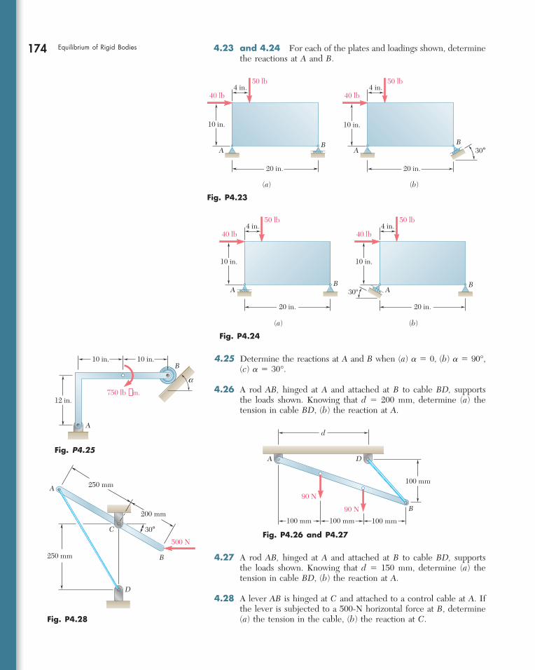
P 4 kN 20 kN
2 m 2 m3 m 3 m
Fig. P4.12 and P4.13
a
AD C
B
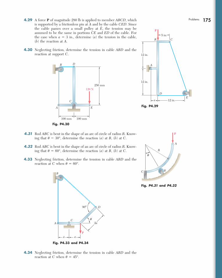
6 in.300 lb 300 lb
50 lb
8 in. 4 in. 12 in.
Fig. P4.14
4.6 Solve Prob. 4.5, assuming that crate D is removed and that the position of crate C is unchanged.
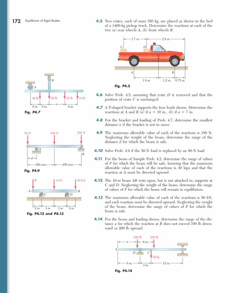
4.7 A T-shaped bracket supports the four loads shown. Determine the reactions at A and B (a) if a 5 10 in., (b) if a 5 7 in.
4.8 For the bracket and loading of Prob. 4.7, determine the smallest distance a if the bracket is not to move.
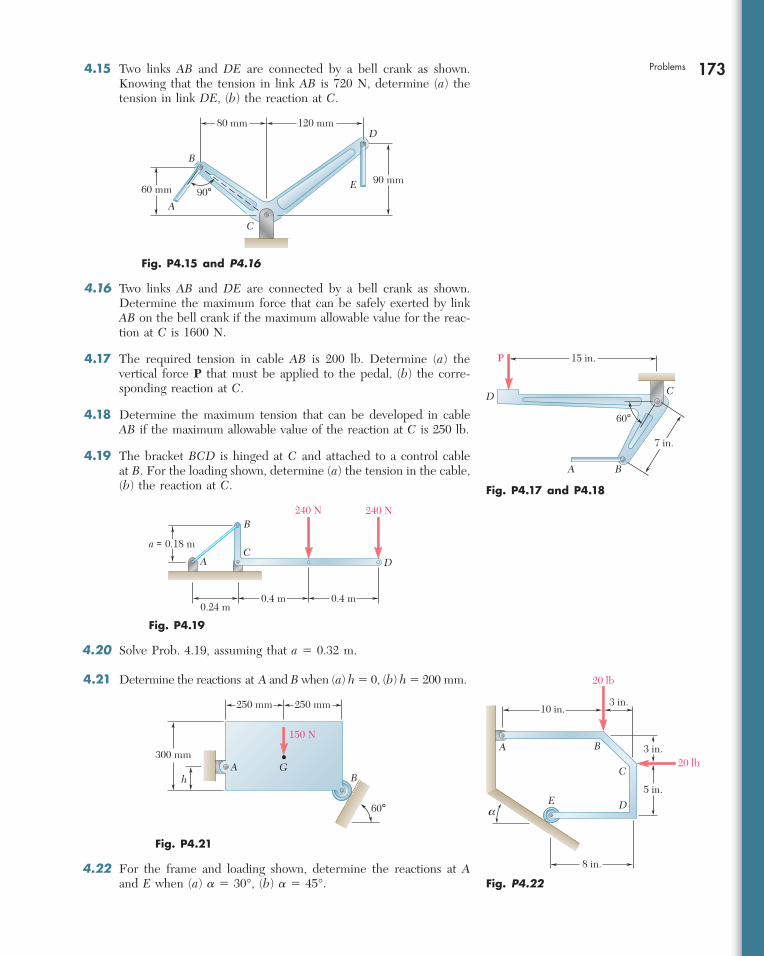
4.9 The maximum allowable value of each of the reactions is 180 N. Neglecting the weight of the beam, determine the range of the distance d for which the beam is safe.
4.10 Solve Prob. 4.9 if the 50-N load is replaced by an 80-N load.
4.11 For the beam of Sample Prob. 4.2, determine the range of values of P for which the beam will be safe, knowing that the maximum allowable value of each of the reactions is 30 kips and that the reaction at A must be directed upward.
4.12 The 10-m beam AB rests upon, but is not attached to, supports at C and D. Neglecting the weight of the beam, determine the range of values of P for which the beam will remain in equilibrium.
4.13 The maximum allowable value of each of the reactions is 50 kN, and each reaction must be directed upward. Neglecting the weight of the beam, determine the range of values of P for which the beam is safe.
4.14 For the beam and loading shown, determine the range of the dis-tance a for which the reaction at B does not exceed 100 lb down-ward or 200 lb upward.
Fig. P4.7
6 in. 6 in. 8 in.
10 lb30 lb50 lb40 lb
A
B
a
C D
G
1.7 m 2.8 m
A B
1.8 m 1.2 m 0.75 m
Fig. P4.5
50 N 100 N 150 N
450 mm
d
A
B
450 mm
Fig. P4.9
bee29400_ch04_156-217.indd Page 172 11/29/08 3:33:41 PM user-s172bee29400_ch04_156-217.indd Page 172 11/29/08 3:33:41 PM user-s172 /Volumes/204/MHDQ076/work%0/indd%0/Volumes/204/MHDQ076/work%0/indd%0
173Problems 4.15 Two links AB and DE are connected by a bell crank as shown. Knowing that the tension in link AB is 720 N, determine (a) the tension in link DE, (b) the reaction at C.
A
B
E
D
C
90°60 mm90 mm
80 mm 120 mm
Fig. P4.15 and P4.16
P
D
A B
C
15 in.
7 in.
60°
Fig. P4.17 and P4.18
240 N 240 N
0.24 m0.4 m 0.4 m
A
B
CD
a = 0.18 m
Fig. P4.19
60°
300 mm
250 mm 250 mm
150 N
GB
Ah
Fig. P4.21
4.16 Two links AB and DE are connected by a bell crank as shown. Determine the maximum force that can be safely exerted by link AB on the bell crank if the maximum allowable value for the reac-tion at C is 1600 N.
4.17 The required tension in cable AB is 200 lb. Determine (a) the vertical force P that must be applied to the pedal, (b) the corre-sponding reaction at C.
4.18 Determine the maximum tension that can be developed in cable AB if the maximum allowable value of the reaction at C is 250 lb.
4.19 The bracket BCD is hinged at C and attached to a control cable at B. For the loading shown, determine (a) the tension in the cable, (b) the reaction at C.
4.20 Solve Prob. 4.19, assuming that a 5 0.32 m.
4.21 Determine the reactions at A and B when (a) h 5 0, (b) h 5 200 mm.
10 in.3 in.
20 lb
20 lb
a
A B
DE
C
8 in.
5 in.
3 in.
Fig. P4.22 4.22 For the frame and loading shown, determine the reactions at A
and E when (a) a 5 30°, (b) a 5 45°.
bee29400_ch04_156-217.indd Page 173 11/29/08 3:33:42 PM user-s172bee29400_ch04_156-217.indd Page 173 11/29/08 3:33:42 PM user-s172 /Volumes/204/MHDQ076/work%0/indd%0/Volumes/204/MHDQ076/work%0/indd%0
174 Equilibrium of Rigid Bodies
B
D
30°
500 N
C
200 mm
250 mm
250 mm
A
Fig. P4.28
4.27 A rod AB, hinged at A and attached at B to cable BD, supports the loads shown. Knowing that d 5 150 mm, determine (a) the tension in cable BD, (b) the reaction at A.
4.28 A lever AB is hinged at C and attached to a control cable at A. If the lever is subjected to a 500-N horizontal force at B, determine (a) the tension in the cable, (b) the reaction at C.
4.23 and 4.24 For each of the plates and loadings shown, determine the reactions at A and B.
40 lb 40 lb
50 lb 50 lb
AB
(a)
30°
10 in.
AB
(b)
20 in.
10 in.
4 in. 4 in.
20 in.
Fig. P4.23
40 lb 40 lb
50 lb 50 lb
AB
(a)
30º
20 in.
10 in.
AB
(b)
20 in.
10 in.
4 in. 4 in.
Fig. P4.24
4.25 Determine the reactions at A and B when (a) a 5 0, (b) a 5 90°, (c) a 5 30°.
4.26 A rod AB, hinged at A and attached at B to cable BD, supports the loads shown. Knowing that d 5 200 mm, determine (a) the tension in cable BD, (b) the reaction at A.
10 in. 10 in.
12 in.
a
A
B
750 lb ⋅ in.
Fig. P4.25
90 N
100 mm
100 mm100 mm100 mm
A
B
d
D
90 N
Fig. P4.26 and P4.27
bee29400_ch04_156-217.indd Page 174 11/29/08 3:33:43 PM user-s172bee29400_ch04_156-217.indd Page 174 11/29/08 3:33:43 PM user-s172 /Volumes/204/MHDQ076/work%0/indd%0/Volumes/204/MHDQ076/work%0/indd%0
175Problems 4.29 A force P of magnitude 280 lb is applied to member ABCD, which is supported by a frictionless pin at A and by the cable CED. Since the cable passes over a small pulley at E, the tension may be assumed to be the same in portions CE and ED of the cable. For the case when a 5 3 in., determine (a) the tension in the cable, (b) the reaction at A.
4.30 Neglecting friction, determine the tension in cable ABD and the reaction at support C.
A
B C
DE
P
a 12 in.
5 in.
12 in.
12 in.
Fig. P4.29A E
C
120 N
100 mm 100 mm
B D
250 mm
Fig. P4.30
A
BC
R
P
q
Fig. P4.31 and P4.32
A
B
D
C
90°
P
q
a a
2a
Fig. P4.33 and P4.34
4.31 Rod ABC is bent in the shape of an arc of circle of radius R. Know-ing that u 5 30°, determine the reaction (a) at B, (b) at C.
4.32 Rod ABC is bent in the shape of an arc of circle of radius R. Know-ing that u 5 60°, determine the reaction (a) at B, (b) at C.
4.33 Neglecting friction, determine the tension in cable ABD and the reaction at C when u 5 60°.
4.34 Neglecting friction, determine the tension in cable ABD and the reaction at C when u 5 45°.
bee29400_ch04_156-217.indd Page 175 11/29/08 3:33:43 PM user-s172bee29400_ch04_156-217.indd Page 175 11/29/08 3:33:43 PM user-s172 /Volumes/204/MHDQ076/work%0/indd%0/Volumes/204/MHDQ076/work%0/indd%0
176 Equilibrium of Rigid Bodies
120 lb
30°A
BC
D
8 in.
8 in.
8 in.
Fig. P4.35
A50 lb
B
C
D
E
5 in.
8 in.
7 in.3 in.
Fig. P4.36
400 N
400 N
100 mm
150 mm
100 mm300 mm
500 mm
A
B
C
D
250 mm
Fig. P4.37
600 N
100 mm100 mm100 mm
80 mm
80 mmA B C D
E
F
Fig. P4.38
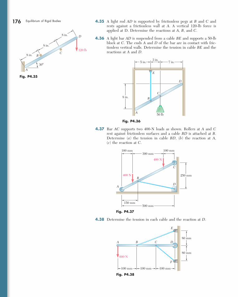
4.35 A light rod AD is supported by frictionless pegs at B and C and rests against a frictionless wall at A. A vertical 120-lb force is applied at D. Determine the reactions at A, B, and C.
4.36 A light bar AD is suspended from a cable BE and supports a 50-lb block at C. The ends A and D of the bar are in contact with fric-tionless vertical walls. Determine the tension in cable BE and the reactions at A and D.
4.37 Bar AC supports two 400-N loads as shown. Rollers at A and C rest against frictionless surfaces and a cable BD is attached at B. Determine (a) the tension in cable BD, (b) the reaction at A, (c) the reaction at C.
4.38 Determine the tension in each cable and the reaction at D.
bee29400_ch04_156-217.indd Page 176 11/29/08 3:33:44 PM user-s172bee29400_ch04_156-217.indd Page 176 11/29/08 3:33:44 PM user-s172 /Volumes/204/MHDQ076/work%0/indd%0/Volumes/204/MHDQ076/work%0/indd%0
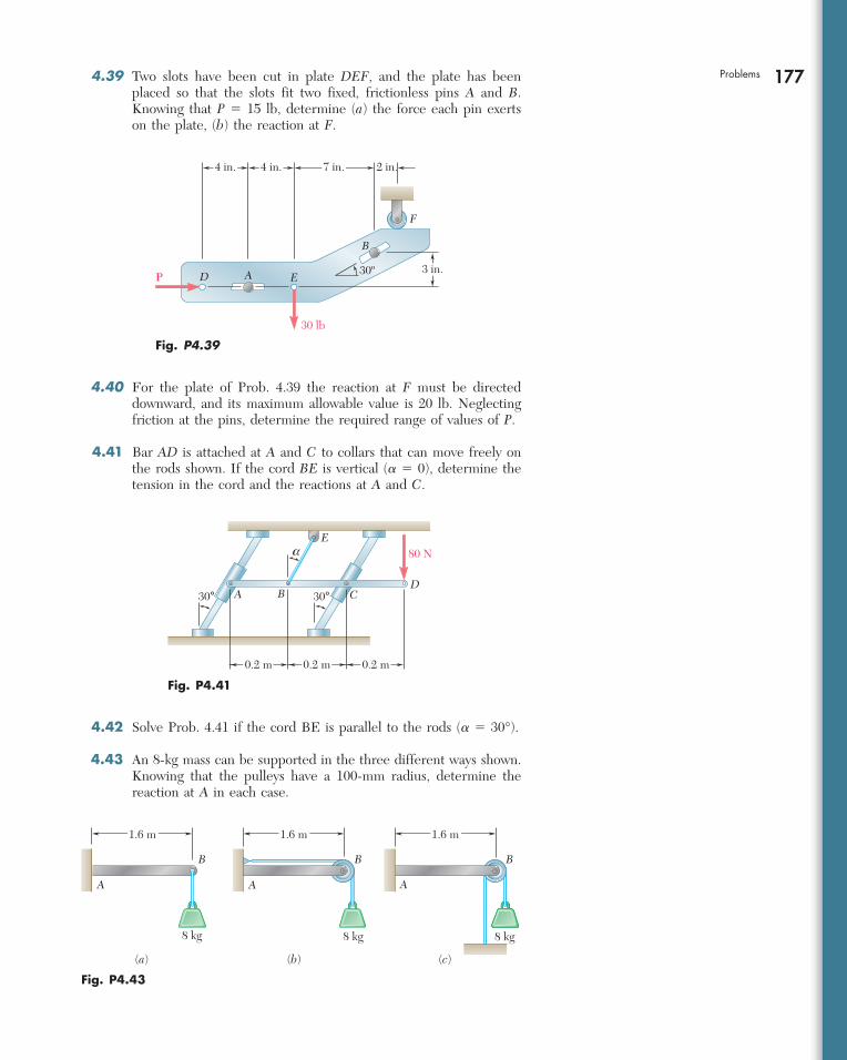
177Problems 4.39 Two slots have been cut in plate DEF, and the plate has been placed so that the slots fit two fixed, frictionless pins A and B. Knowing that P 5 15 lb, determine (a) the force each pin exerts on the plate, (b) the reaction at F.
P A
B
D E
F
4 in. 4 in. 7 in. 2 in.
30º
30 lb
3 in.
Fig. P4.39
4.40 For the plate of Prob. 4.39 the reaction at F must be directed downward, and its maximum allowable value is 20 lb. Neglecting friction at the pins, determine the required range of values of P.
4.41 Bar AD is attached at A and C to collars that can move freely on the rods shown. If the cord BE is vertical (a 5 0), determine the tension in the cord and the reactions at A and C.
A B
E
CD
30°
80 Na
0.2 m 0.2 m
30°
0.2 m
Fig. P4.41
4.42 Solve Prob. 4.41 if the cord BE is parallel to the rods (a 5 30°).
4.43 An 8-kg mass can be supported in the three different ways shown. Knowing that the pulleys have a 100-mm radius, determine the reaction at A in each case.
B
A A A
B B
8 kg 8 kg 8 kg
(a) (b) (c)
1.6 m 1.6 m 1.6 m
Fig. P4.43
bee29400_ch04_156-217.indd Page 177 11/29/08 3:33:44 PM user-s172bee29400_ch04_156-217.indd Page 177 11/29/08 3:33:44 PM user-s172 /Volumes/204/MHDQ076/work%0/indd%0/Volumes/204/MHDQ076/work%0/indd%0
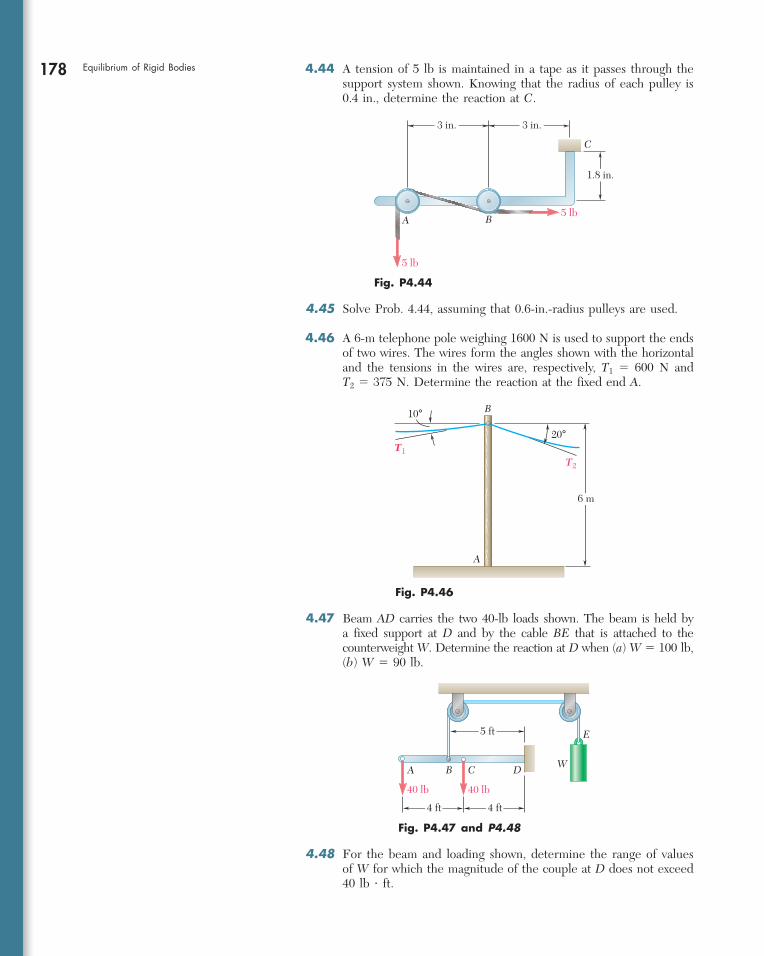
178 Equilibrium of Rigid Bodies 4.44 A tension of 5 lb is maintained in a tape as it passes through the support system shown. Knowing that the radius of each pulley is 0.4 in., determine the reaction at C.
4.45 Solve Prob. 4.44, assuming that 0.6-in.-radius pulleys are used.
4.46 A 6-m telephone pole weighing 1600 N is used to support the ends of two wires. The wires form the angles shown with the horizontal and the tensions in the wires are, respectively, T1 5 600 N and T2 5 375 N. Determine the reaction at the fixed end A.
C
5 lb
5 lb
3 in. 3 in.
1.8 in.
A B
Fig. P4.44
A
B
6 m
20°T1
T2
10°
Fig. P4.46
A B C D
40 lb 40 lb
E5 ft
4 ft4 ft
W
Fig. P4.47 and P4.48
4.47 Beam AD carries the two 40-lb loads shown. The beam is held by a fixed support at D and by the cable BE that is attached to the counterweight W. Determine the reaction at D when (a) W 5 100 lb, (b) W 5 90 lb.
4.48 For the beam and loading shown, determine the range of values of W for which the magnitude of the couple at D does not exceed 40 lb ? ft.
bee29400_ch04_156-217.indd Page 178 11/29/08 3:33:45 PM user-s172bee29400_ch04_156-217.indd Page 178 11/29/08 3:33:45 PM user-s172 /Volumes/204/MHDQ076/work%0/indd%0/Volumes/204/MHDQ076/work%0/indd%0
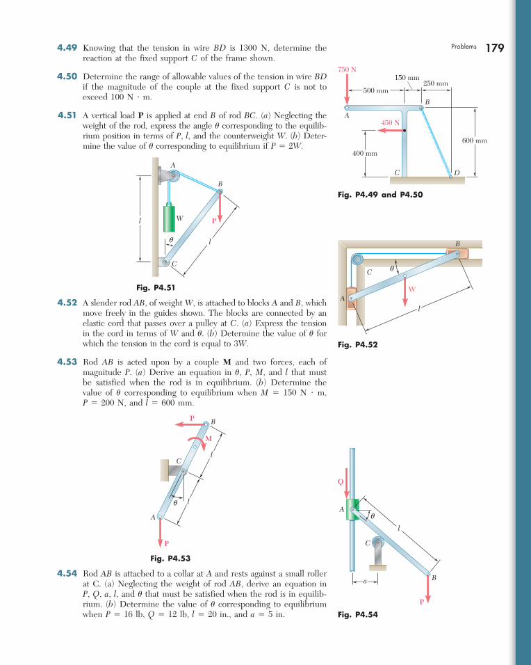
179Problems 4.49 Knowing that the tension in wire BD is 1300 N, determine the reaction at the fixed support C of the frame shown.
4.50 Determine the range of allowable values of the tension in wire BD if the magnitude of the couple at the fixed support C is not to exceed 100 N ? m.
4.51 A vertical load P is applied at end B of rod BC. (a) Neglecting the weight of the rod, express the angle u corresponding to the equilib-rium position in terms of P, l, and the counterweight W. (b) Deter-mine the value of u corresponding to equilibrium if P 5 2W.
750 N
500 mm
150 mm250 mm
600 mm
450 NA
B
C D
400 mm
Fig. P4.49 and P4.50
P
B
C
l
l
q
W
A
Fig. P4.51A
B
C
W
q
l
Fig. P4.52
4.52 A slender rod AB, of weight W, is attached to blocks A and B, which move freely in the guides shown. The blocks are connected by an elastic cord that passes over a pulley at C. (a) Express the tension in the cord in terms of W and u. (b) Determine the value of u for which the tension in the cord is equal to 3W.
4.53 Rod AB is acted upon by a couple M and two forces, each of magnitude P. (a) Derive an equation in u, P, M, and l that must be satisfied when the rod is in equilibrium. (b) Determine the value of u corresponding to equilibrium when M 5 150 N ? m, P 5 200 N, and l 5 600 mm.
A
B
C
l
l
P
P
q
M
Fig. P4.53
A
B
C
Q
P
q
l
a
Fig. P4.54
4.54 Rod AB is attached to a collar at A and rests against a small roller at C. (a) Neglecting the weight of rod AB, derive an equation in P, Q, a, l, and u that must be satisfied when the rod is in equilib-rium. (b) Determine the value of u corresponding to equilibrium when P 5 16 lb, Q 5 12 lb, l 5 20 in., and a 5 5 in.
bee29400_ch04_156-217.indd Page 179 11/29/08 3:33:45 PM user-s172bee29400_ch04_156-217.indd Page 179 11/29/08 3:33:45 PM user-s172 /Volumes/204/MHDQ076/work%0/indd%0/Volumes/204/MHDQ076/work%0/indd%0
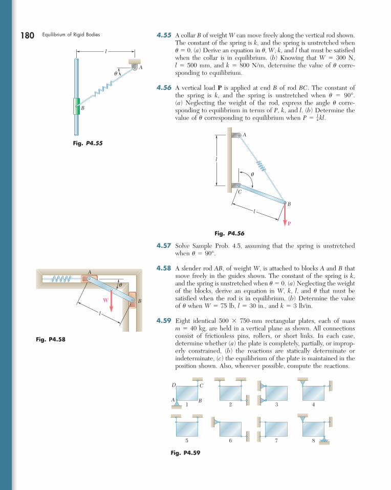
180 Equilibrium of Rigid Bodies 4.55 A collar B of weight W can move freely along the vertical rod shown. The constant of the spring is k, and the spring is unstretched when u 5 0. (a) Derive an equation in u, W, k, and l that must be satisfied when the collar is in equilibrium. (b) Knowing that W 5 300 N, l 5 500 mm, and k 5 800 N/m, determine the value of u corre-sponding to equilibrium.
4.56 A vertical load P is applied at end B of rod BC. The constant of the spring is k, and the spring is unstretched when u 5 90°. (a) Neglecting the weight of the rod, express the angle u corre-sponding to equilibrium in terms of P, k, and l. (b) Determine the value of u corresponding to equilibrium when P 5 1
4 kl.
4.57 Solve Sample Prob. 4.5, assuming that the spring is unstretched when u 5 90°.
4.58 A slender rod AB, of weight W, is attached to blocks A and B that move freely in the guides shown. The constant of the spring is k, and the spring is unstretched when u 5 0. (a) Neglecting the weight of the blocks, derive an equation in W, k, l, and u that must be satisfied when the rod is in equilibrium. (b) Determine the value of u when W 5 75 lb, l 5 30 in., and k 5 3 lb/in.
4.59 Eight identical 500 3 750-mm rectangular plates, each of mass m 5 40 kg, are held in a vertical plane as shown. All connections consist of frictionless pins, rollers, or short links. In each case, determine whether (a) the plate is completely, partially, or improp-erly constrained, (b) the reactions are statically determinate or indeterminate, (c) the equilibrium of the plate is maintained in the position shown. Also, wherever possible, compute the reactions.
A
B
q
l
Fig. P4.55A
B
C
P
q
l
l
Fig. P4.56
A
BW
q
l
Fig. P4.58
Fig. P4.59
A B
CD
1 2 3 4
5 6 7 8
bee29400_ch04_156-217.indd Page 180 11/29/08 3:33:46 PM user-s172bee29400_ch04_156-217.indd Page 180 11/29/08 3:33:46 PM user-s172 /Volumes/204/MHDQ076/work%0/indd%0/Volumes/204/MHDQ076/work%0/indd%0
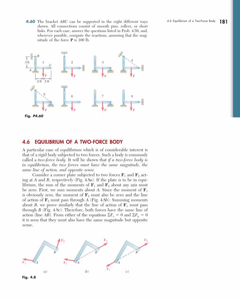
181 4.60 The bracket ABC can be supported in the eight different ways shown. All connections consist of smooth pins, rollers, or short links. For each case, answer the questions listed in Prob. 4.59, and, wherever possible, compute the reactions, assuming that the mag-nitude of the force P is 100 lb.
4.6 EQUILIBRIUM OF A TWO-FORCE BODYA particular case of equilibrium which is of considerable interest is that of a rigid body subjected to two forces. Such a body is commonly called a two-force body. It will be shown that if a two-force body is in equilibrium, the two forces must have the same magnitude, the same line of action, and opposite sense. Consider a corner plate subjected to two forces F1 and F2 act-ing at A and B, respectively (Fig. 4.8a). If the plate is to be in equi-librium, the sum of the moments of F1 and F2 about any axis must be zero. First, we sum moments about A. Since the moment of F1 is obviously zero, the moment of F2 must also be zero and the line of action of F2 must pass through A (Fig. 4.8b). Summing moments about B, we prove similarly that the line of action of F1 must pass through B (Fig. 4.8c). Therefore, both forces have the same line of action (line AB). From either of the equations oFx 5 0 and oFy 5 0 it is seen that they must also have the same magnitude but opposite sense.
B
AC
13 ft
2 ft 2 ft
2 34
5 6 7 8
PPP
P P P P
P
Fig. P4.60
(c)
A
B
F1
F2
(b)
A
B
F2
(a)
A
B
F1
F2
F1
Fig. 4.8
1814.6 Equilibrium of a Two-Force Body
bee29400_ch04_156-217.indd Page 181 11/29/08 3:33:47 PM user-s172bee29400_ch04_156-217.indd Page 181 11/29/08 3:33:47 PM user-s172 /Volumes/204/MHDQ076/work%0/indd%0/Volumes/204/MHDQ076/work%0/indd%0
182 Equilibrium of Rigid Bodies
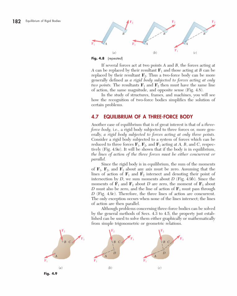
If several forces act at two points A and B, the forces acting at A can be replaced by their resultant F1 and those acting at B can be replaced by their resultant F2. Thus a two-force body can be more generally defined as a rigid body subjected to forces acting at only two points. The resultants F1 and F2 then must have the same line of action, the same magnitude, and opposite sense (Fig. 4.8). In the study of structures, frames, and machines, you will see how the recognition of two-force bodies simplifies the solution of certain problems.
4.7 EQUILIBRIUM OF A THREE-FORCE BODYAnother case of equilibrium that is of great interest is that of a three-force body, i.e., a rigid body subjected to three forces or, more gen-erally, a rigid body subjected to forces acting at only three points. Consider a rigid body subjected to a system of forces which can be reduced to three forces F1, F2, and F3 acting at A, B, and C, respec-tively (Fig. 4.9a). It will be shown that if the body is in equilibrium, the lines of action of the three forces must be either concurrent or parallel. Since the rigid body is in equilibrium, the sum of the moments of F1, F2, and F3 about any axis must be zero. Assuming that the lines of action of F1 and F2 intersect and denoting their point of intersection by D, we sum moments about D (Fig. 4.9b). Since the moments of F1 and F2 about D are zero, the moment of F3 about D must also be zero, and the line of action of F3 must pass through D (Fig. 4.9c). Therefore, the three lines of action are concurrent. The only exception occurs when none of the lines intersect; the lines of action are then parallel. Although problems concerning three-force bodies can be solved by the general methods of Secs. 4.3 to 4.5, the property just estab-lished can be used to solve them either graphically or mathematically from simple trigonometric or geometric relations.
(c)
A
B
F1
F2
(b)
A
B
F2
(a)
A
B
F1
F2
F1
Fig. 4.8 (repeated)
F2
F3
F1
B C
DA
(a) (b) (c)
F2
F3
F1
B C
DA
F2
F3
F1
B C
A
Fig. 4.9
bee29400_ch04_156-217.indd Page 182 11/29/08 3:33:47 PM user-s172bee29400_ch04_156-217.indd Page 182 11/29/08 3:33:47 PM user-s172 /Volumes/204/MHDQ076/work%0/indd%0/Volumes/204/MHDQ076/work%0/indd%0
183
SOLUTION
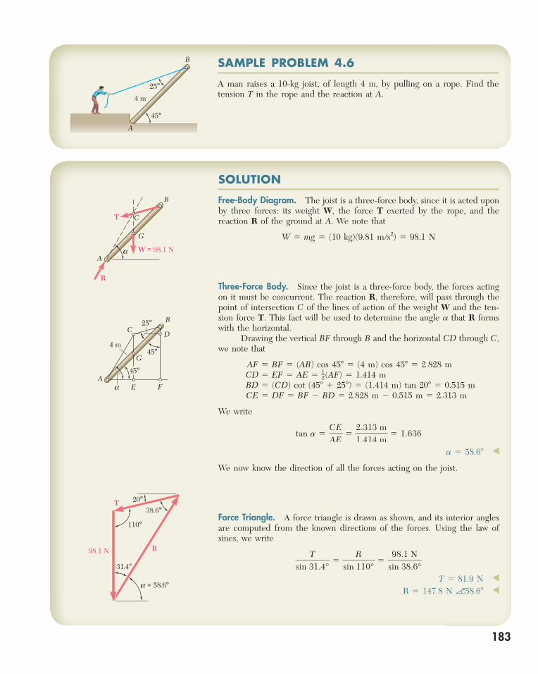
Free-Body Diagram. The joist is a three-force body, since it is acted upon by three forces: its weight W, the force T exerted by the rope, and the reaction R of the ground at A. We note that
W 5 mg 5 (10 kg)(9.81 m/s2) 5 98.1 N
Three-Force Body. Since the joist is a three-force body, the forces acting on it must be concurrent. The reaction R, therefore, will pass through the point of intersection C of the lines of action of the weight W and the ten-sion force T. This fact will be used to determine the angle a that R forms with the horizontal. Drawing the vertical BF through B and the horizontal CD through C, we note that
AF 5 BF 5 (AB) cos 458 5 (4 m) cos 458 5 2.828 mCD 5 EF 5 AE 5 1
2(AF) 5 1.414 mBD 5 (CD) cot (458 1 258) 5 (1.414 m) tan 208 5 0.515 m CE 5 DF 5 BF 2 BD 5 2.828 m 2 0.515 m 5 2.313 m
We write
tan a 5CEAE
52.313 m1.414 m
5 1.636
a 5 58.68 ◀
We now know the direction of all the forces acting on the joist.
Force Triangle. A force triangle is drawn as shown, and its interior angles are computed from the known directions of the forces. Using the law of sines, we write
Tsin 31.4°
5R
sin 110°5
98.1 Nsin 38.6°
T 5 81.9 N ◀
R 5 147.8 N a58.68 ◀
SAMPLE PROBLEM 4.6
A man raises a 10-kg joist, of length 4 m, by pulling on a rope. Find the tension T in the rope and the reaction at A.
45°
25°4 m
B
A
A
B
C
G
T
R
W = 98.1 Na
45°
45°4 m
A
BC
G
D
E F
25°
a
T
R98.1 N
110°
38.6°20°
31.4°
a = 58.6°
bee29400_ch04_156-217.indd Page 183 11/29/08 3:33:47 PM user-s172bee29400_ch04_156-217.indd Page 183 11/29/08 3:33:47 PM user-s172 /Volumes/204/MHDQ076/work%0/indd%0/Volumes/204/MHDQ076/work%0/indd%0
184
The preceding sections covered two particular cases of equilibrium of a rigid body.
1. A two-force body is a body subjected to forces at only two points. The resultants of the forces acting at each of these points must have the same magni-tude, the same line of action, and opposite sense. This property will allow you to simplify the solutions of some problems by replacing the two unknown compo-nents of a reaction by a single force of unknown magnitude but of known direction.
2. A three-force body is subjected to forces at only three points. The resul-tants of the forces acting at each of these points must be concurrent or parallel. To solve a problem involving a three-force body with concurrent forces, draw your free-body diagram showing that these three forces pass through the same point. The use of simple geometry may then allow you to complete the solution by using a force triangle [Sample Prob. 4.6].
Although the principle noted above for the solution of problems involving three-force bodies is easily understood, it can be difficult to sketch the needed geo-metric constructions. If you encounter difficulty, first draw a reasonably large free-body diagram and then seek a relation between known or easily calculated lengths and a dimension that involves an unknown. This was done in Sample Prob. 4.6, where the easily calculated dimensions AE and CE were used to determine the angle a.
SOLVING PROBLEMSON YOUR OWN
bee29400_ch04_156-217.indd Page 184 11/29/08 3:33:48 PM user-s172bee29400_ch04_156-217.indd Page 184 11/29/08 3:33:48 PM user-s172 /Volumes/204/MHDQ076/work%0/indd%0/Volumes/204/MHDQ076/work%0/indd%0
PROBLEMS
185
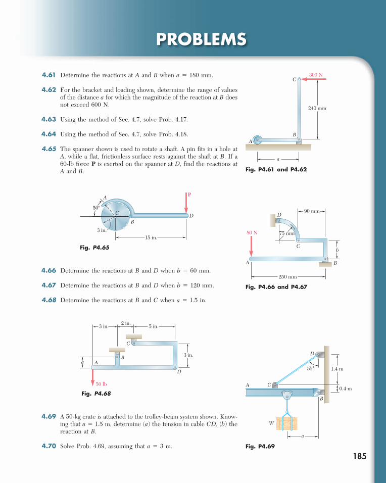
4.61 Determine the reactions at A and B when a 5 180 mm.
4.62 For the bracket and loading shown, determine the range of values of the distance a for which the magnitude of the reaction at B does not exceed 600 N.
4.63 Using the method of Sec. 4.7, solve Prob. 4.17.
4.64 Using the method of Sec. 4.7, solve Prob. 4.18.
4.65 The spanner shown is used to rotate a shaft. A pin fits in a hole at A, while a flat, frictionless surface rests against the shaft at B. If a 60-lb force P is exerted on the spanner at D, find the reactions at A and B.
AB
C
240 mm
300 N
a
Fig. P4.61 and P4.62
Fig. P4.65
15 in.3 in.
PA
B
C D50º
4.66 Determine the reactions at B and D when b 5 60 mm.
4.67 Determine the reactions at B and D when b 5 120 mm.
4.68 Determine the reactions at B and C when a 5 1.5 in.
Fig. P4.66 and P4.67
A B
C
D
75 mm80 N
90 mm
b
250 mm
5 in.2 in.3 in.
3 in.
50 lb
A
C
B
D
a
Fig. P4.68
4.69 A 50-kg crate is attached to the trolley-beam system shown. Know-ing that a 5 1.5 m, determine (a) the tension in cable CD, (b) the reaction at B.
4.70 Solve Prob. 4.69, assuming that a 5 3 m.
A
B
C
D
55° 1.4 m
0.4 m
a
W
Fig. P4.69
bee29400_ch04_156-217.indd Page 185 11/29/08 3:33:49 PM user-s172bee29400_ch04_156-217.indd Page 185 11/29/08 3:33:49 PM user-s172 /Volumes/204/MHDQ076/work%0/indd%0/Volumes/204/MHDQ076/work%0/indd%0
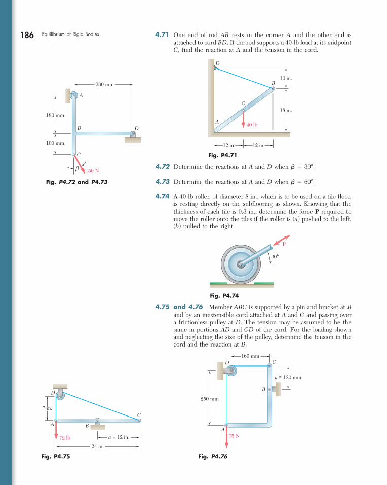
186 Equilibrium of Rigid Bodies 4.71 One end of rod AB rests in the corner A and the other end is attached to cord BD. If the rod supports a 40-lb load at its midpoint C, find the reaction at A and the tension in the cord.
40 lbA
B
C
D
12 in. 12 in.
18 in.
10 in.
Fig. P4.71
4.72 Determine the reactions at A and D when b 5 308.
4.73 Determine the reactions at A and D when b 5 608.
4.74 A 40-lb roller, of diameter 8 in., which is to be used on a tile floor, is resting directly on the subflooring as shown. Knowing that the thickness of each tile is 0.3 in., determine the force P required to move the roller onto the tiles if the roller is (a) pushed to the left, (b) pulled to the right.
Fig. P4.72 and P4.73
A
B
C
D
150 Nb
180 mm
100 mm
280 mm
30°
P
Fig. P4.74
A B
D
C
72 lb a = 12 in.
7 in.
24 in.
Fig. P4.75
A
B
CD
75 N
250 mm
a = 120 mm
160 mm
Fig. P4.76
4.75 and 4.76 Member ABC is supported by a pin and bracket at B and by an inextensible cord attached at A and C and passing over a frictionless pulley at D. The tension may be assumed to be the same in portions AD and CD of the cord. For the loading shown and neglecting the size of the pulley, determine the tension in the cord and the reaction at B.
bee29400_ch04_156-217.indd Page 186 12/9/08 1:43:58 AM user-s173bee29400_ch04_156-217.indd Page 186 12/9/08 1:43:58 AM user-s173 /Volumes/204/MHDQ076/work%0/indd%0/Volumes/204/MHDQ076/work%0/indd%0
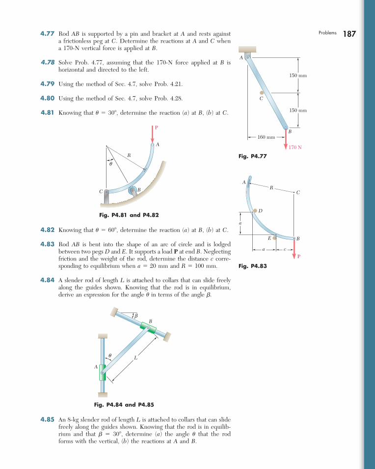
187Problems 4.77 Rod AB is supported by a pin and bracket at A and rests against a frictionless peg at C. Determine the reactions at A and C when a 170-N vertical force is applied at B.
4.78 Solve Prob. 4.77, assuming that the 170-N force applied at B is horizontal and directed to the left.
4.79 Using the method of Sec. 4.7, solve Prob. 4.21.
4.80 Using the method of Sec. 4.7, solve Prob. 4.28.
4.81 Knowing that u 5 308, determine the reaction (a) at B, (b) at C.
4.82 Knowing that u 5 608, determine the reaction (a) at B, (b) at C.
4.83 Rod AB is bent into the shape of an arc of circle and is lodged between two pegs D and E. It supports a load P at end B. Neglecting friction and the weight of the rod, determine the distance c corre-sponding to equilibrium when a 5 20 mm and R 5 100 mm.
4.84 A slender rod of length L is attached to collars that can slide freely along the guides shown. Knowing that the rod is in equilibrium, derive an expression for the angle u in terms of the angle b.
A
B
C
170 N
150 mm
150 mm
160 mm
Fig. P4.77
A
BC
R
P
q
Fig. P4.81 and P4.82
P
AR
C
D
E
a
a
c
B
Fig. P4.83
A
B
q
b
L
Fig. P4.84 and P4.85
4.85 An 8-kg slender rod of length L is attached to collars that can slide freely along the guides shown. Knowing that the rod is in equilib-rium and that b 5 308, determine (a) the angle u that the rod forms with the vertical, (b) the reactions at A and B.
bee29400_ch04_156-217.indd Page 187 11/29/08 3:33:52 PM user-s172bee29400_ch04_156-217.indd Page 187 11/29/08 3:33:52 PM user-s172 /Volumes/204/MHDQ076/work%0/indd%0/Volumes/204/MHDQ076/work%0/indd%0
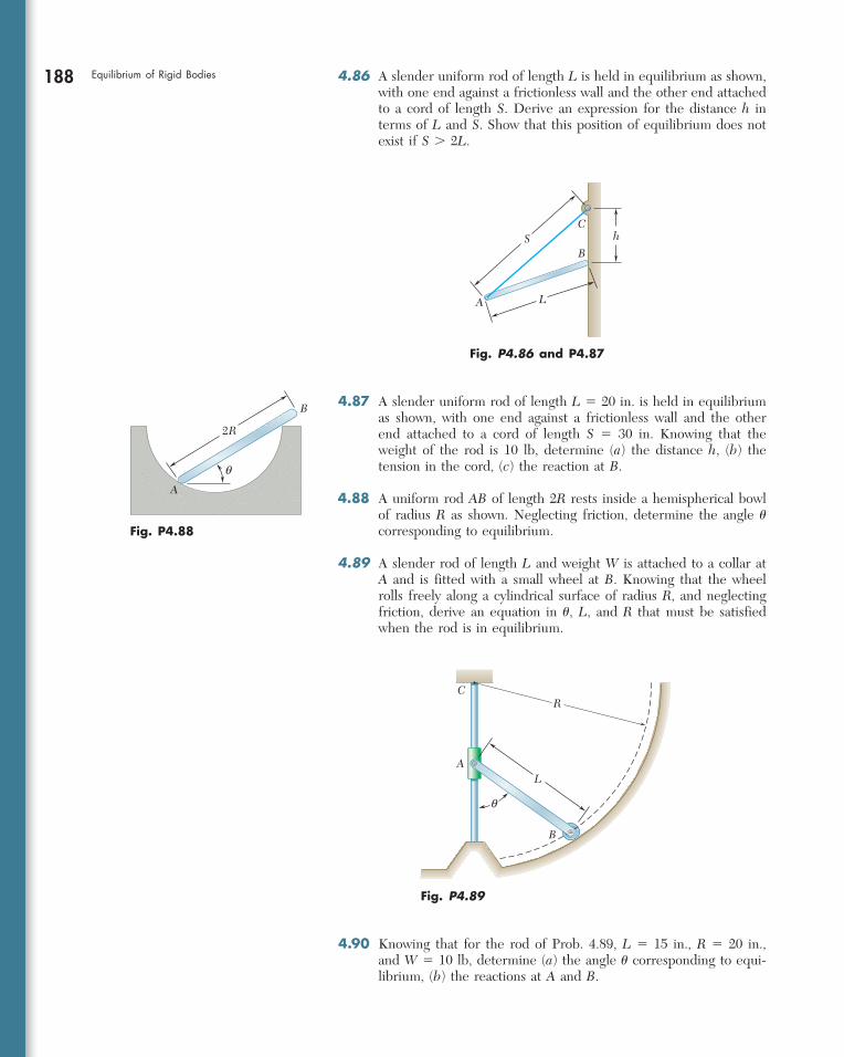
188 Equilibrium of Rigid Bodies 4.86 A slender uniform rod of length L is held in equilibrium as shown, with one end against a frictionless wall and the other end attached to a cord of length S. Derive an expression for the distance h in terms of L and S. Show that this position of equilibrium does not exist if S . 2L.
B
A
CS
L
h
Fig. P4.86 and P4.87
A
B
q
2R
Fig. P4.88
4.87 A slender uniform rod of length L 5 20 in. is held in equilibrium as shown, with one end against a frictionless wall and the other end attached to a cord of length S 5 30 in. Knowing that the weight of the rod is 10 lb, determine (a) the distance h, (b) the tension in the cord, (c) the reaction at B.
4.88 A uniform rod AB of length 2R rests inside a hemispherical bowl of radius R as shown. Neglecting friction, determine the angle u corresponding to equilibrium.
4.89 A slender rod of length L and weight W is attached to a collar at A and is fitted with a small wheel at B. Knowing that the wheel rolls freely along a cylindrical surface of radius R, and neglecting friction, derive an equation in u, L, and R that must be satisfied when the rod is in equilibrium.
R
LA
B
C
q
Fig. P4.89
4.90 Knowing that for the rod of Prob. 4.89, L 5 15 in., R 5 20 in., and W 5 10 lb, determine (a) the angle u corresponding to equi-librium, (b) the reactions at A and B.
bee29400_ch04_156-217.indd Page 188 11/29/08 3:33:52 PM user-s172bee29400_ch04_156-217.indd Page 188 11/29/08 3:33:52 PM user-s172 /Volumes/204/MHDQ076/work%0/indd%0/Volumes/204/MHDQ076/work%0/indd%0
189EQUILIBRIUM IN THREE DIMENSIONS
4.8 EQUILIBRIUM OF A RIGID BODY IN THREE DIMENSIONS
We saw in Sec. 4.1 that six scalar equations are required to express the conditions for the equilibrium of a rigid body in the general three-dimensional case:
oFx 5 0 oFy 5 0 oFz 5 0 (4.2) oMx 5 0 oMy 5 0 oMz 5 0 (4.3)
These equations can be solved for no more than six unknowns, which generally will represent reactions at supports or connections. In most problems the scalar equations (4.2) and (4.3) will be more conveniently obtained if we first express in vector form the con-ditions for the equilibrium of the rigid body considered. We write
oF 5 0 oMO 5 o(r 3 F) 5 0 (4.1)
and express the forces F and position vectors r in terms of scalar components and unit vectors. Next, we compute all vector products, either by direct calculation or by means of determinants (see Sec. 3.8). We observe that as many as three unknown reaction components may be eliminated from these computations through a judicious choice of the point O. By equating to zero the coefficients of the unit vectors in each of the two relations (4.1), we obtain the desired scalar equations.†
4.9 REACTIONS AT SUPPORTS AND CONNECTIONS FOR A THREE-DIMENSIONAL STRUCTURE
The reactions on a three-dimensional structure range from the single force of known direction exerted by a frictionless surface to the force-couple system exerted by a fixed support. Consequently, in problems involving the equilibrium of a three-dimensional structure, there can be between one and six unknowns associated with the reaction at each support or connection. Various types of supports and
†In some problems, it will be found convenient to eliminate the reactions at two points A and B from the solution by writing the equilibrium equation oMAB 5 0, which involves the determination of the moments of the forces about the axis AB joining points A and B (see Sample Prob. 4.10).
4.9 Reactions at Supports and Connections for a Three-Dimensional Structure
bee29400_ch04_156-217.indd Page 189 11/29/08 3:33:53 PM user-s172bee29400_ch04_156-217.indd Page 189 11/29/08 3:33:53 PM user-s172 /Volumes/204/MHDQ076/work%0/indd%0/Volumes/204/MHDQ076/work%0/indd%0
190 Equilibrium of Rigid Bodies connections are shown in Fig. 4.10 with their corresponding reac-tions. A simple way of determining the type of reaction correspond-ing to a given support or connection and the number of unknowns involved is to find which of the six fundamental motions (translation in the x, y, and z directions, rotation about the x, y, and z axes) are allowed and which motions are prevented. Ball supports, frictionless surfaces, and cables, for example, pre-vent translation in one direction only and thus exert a single force whose line of action is known; each of these supports involves one unknown, namely, the magnitude of the reaction. Rollers on rough surfaces and wheels on rails prevent translation in two directions; the corresponding reactions consist of two unknown force components. Rough surfaces in direct contact and ball-and-socket supports prevent translation in three directions; these supports involve three unknown force components. Some supports and connections can prevent rotation as well as translation; the corresponding reactions include couples as well as forces. For example, the reaction at a fixed support, which prevents any motion (rotation as well as translation), consists of three unknown forces and three unknown couples. A universal joint, which is designed to allow rotation about two axes, will exert a reaction consisting of three unknown force components and one unknown couple. Other supports and connections are primarily intended to pre-vent translation; their design, however, is such that they also prevent some rotations. The corresponding reactions consist essentially of force components but may also include couples. One group of sup-ports of this type includes hinges and bearings designed to support radial loads only (for example, journal bearings, roller bearings). The corresponding reactions consist of two force components but may also include two couples. Another group includes pin-and-bracket supports, hinges, and bearings designed to support an axial thrust as well as a radial load (for example, ball bearings). The corresponding reactions consist of three force components but may include two couples. However, these supports will not exert any appreciable cou-ples under normal conditions of use. Therefore, only force compo-nents should be included in their analysis unless it is found that couples are necessary to maintain the equilibrium of the rigid body, or unless the support is known to have been specifically designed to exert a couple (see Probs. 4.119 through 4.122). If the reactions involve more than six unknowns, there are more unknowns than equations, and some of the reactions are stati-cally indeterminate. If the reactions involve fewer than six unknowns, there are more equations than unknowns, and some of the equations of equilibrium cannot be satisfied under general loading conditions; the rigid body is only partially constrained. Under the particular loading conditions corresponding to a given problem, however, the extra equations often reduce to trivial identities, such as 0 5 0, and can be disregarded; although only partially constrained, the rigid body remains in equilibrium (see Sample Probs. 4.7 and 4.8). Even with six or more unknowns, it is possible that some equations of equilibrium will not be satisfied. This can occur when the reactions associated with the given supports either are parallel or intersect the same line; the rigid body is then improperly constrained.
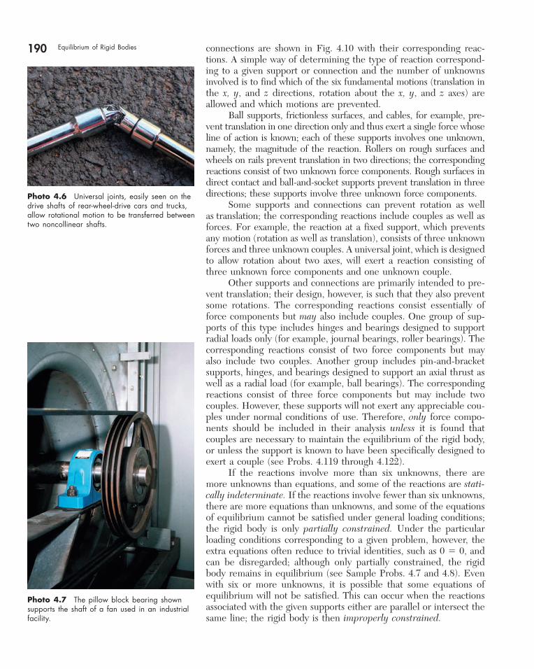
Photo 4.6 Universal joints, easily seen on the drive shafts of rear-wheel-drive cars and trucks, allow rotational motion to be transferred between two noncollinear shafts.
Photo 4.7 The pillow block bearing shown supports the shaft of a fan used in an industrial facility.
bee29400_ch04_156-217.indd Page 190 12/9/08 1:44:03 AM user-s173bee29400_ch04_156-217.indd Page 190 12/9/08 1:44:03 AM user-s173 /Volumes/204/MHDQ076/work%0/indd%0/Volumes/204/MHDQ076/work%0/indd%0
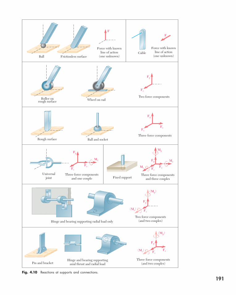
Fig. 4.10 Reactions at supports and connections.
Ball Frictionless surface
Force with knownline of action
(one unknown)
Force with knownline of action
(one unknown)Cable
FF
Roller onrough surface
Rough surface
Universaljoint
Hinge and bearing supporting radial load only
Wheel on railTwo force components
Three force components
Three force componentsand one couple
Three force componentsand three couples
Three force components(and two couples)
Two force components(and two couples)
Fy
Fx
Fx
Mx
Fz
Fy
FzFx
Fy
Fz
Fy
Fz
Fy
Fz
My
(Mz)
(My)
(Mz)
(My)
Mz
Ball and socket
Fixed support
Hinge and bearing supportingaxial thrust and radial loadPin and bracket
Fx
Mx
Fy
Fz
191
bee29400_ch04_156-217.indd Page 191 11/29/08 3:33:55 PM user-s172bee29400_ch04_156-217.indd Page 191 11/29/08 3:33:55 PM user-s172 /Volumes/204/MHDQ076/work%0/indd%0/Volumes/204/MHDQ076/work%0/indd%0
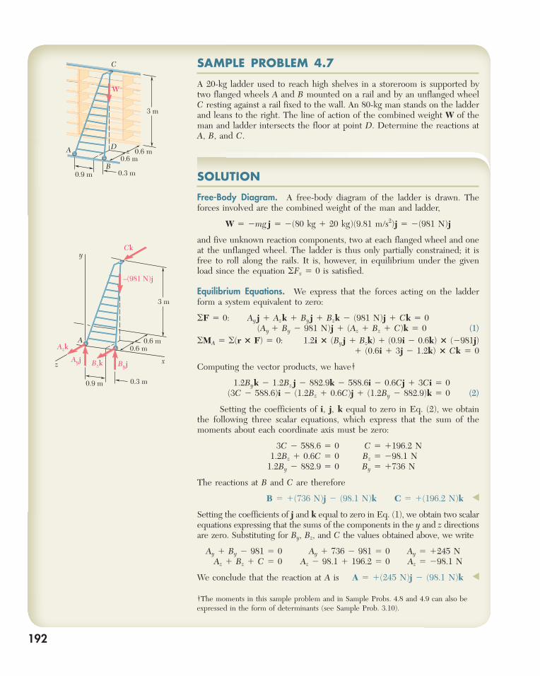
SAMPLE PROBLEM 4.7
A 20-kg ladder used to reach high shelves in a storeroom is supported by two flanged wheels A and B mounted on a rail and by an unflanged wheel C resting against a rail fixed to the wall. An 80-kg man stands on the ladder and leans to the right. The line of action of the combined weight W of the man and ladder intersects the floor at point D. Determine the reactions at A, B, and C.
A 0.6 m0.6 m
0.9 m 0.3 m
x
y
z
Ck
–(981 N)j
Ayj
Azk
Bzk Byj
3 m
192
A
B
C
D0.6 m
0.6 m
0.9 m 0.3 m
W
3 m
SOLUTION
Free-Body Diagram. A free-body diagram of the ladder is drawn. The forces involved are the combined weight of the man and ladder,
W 5 2mg j 5 2(80 kg 1 20 kg)(9.81 m/s2)j 5 2(981 N)j
and five unknown reaction components, two at each flanged wheel and one at the unflanged wheel. The ladder is thus only partially constrained; it is free to roll along the rails. It is, however, in equilibrium under the given load since the equation oFx 5 0 is satisfied.
Equilibrium Equations. We express that the forces acting on the ladder form a system equivalent to zero:
oF 5 0: Ay j 1 Azk 1 Byj 1 Bzk 2 (981 N)j 1 Ck 5 0 (Ay 1 By 2 981 N)j 1 (Az 1 Bz 1 C)k 5 0 (1)oMA 5 o(r 3 F) 5 0: 1.2i 3 (By j 1 Bzk) 1 (0.9i 2 0.6k) 3 (2981j)
1 (0.6i 1 3j 2 1.2k) 3 Ck 5 0
Computing the vector products, we have†
1.2Byk 2 1.2Bz j 2 882.9k 2 588.6i 2 0.6Cj 1 3Ci 5 0 (3C 2 588.6)i 2 (1.2Bz 1 0.6C)j 1 (1.2By 2 882.9)k 5 0 (2)
Setting the coefficients of i, j, k equal to zero in Eq. (2), we obtain the following three scalar equations, which express that the sum of the moments about each coordinate axis must be zero:
3C 2 588.6 5 0 C 5 1196.2 N 1.2Bz 1 0.6C 5 0 Bz 5 298.1 N 1.2By 2 882.9 5 0 By 5 1736 N
The reactions at B and C are therefore
B 5 1(736 N)j 2 (98.1 N)k C 5 1(196.2 N)k ◀
Setting the coefficients of j and k equal to zero in Eq. (1), we obtain two scalar equations expressing that the sums of the components in the y and z directions are zero. Substituting for By, Bz, and C the values obtained above, we write
Ay 1 By 2 981 5 0 Ay 1 736 2 981 5 0 Ay 5 1245 N Az 1 Bz 1 C 5 0 Az 2 98.1 1 196.2 5 0 Az 5 298.1 N
We conclude that the reaction at A is A 5 1(245 N)j 2 (98.1 N)k ◀
†The moments in this sample problem and in Sample Probs. 4.8 and 4.9 can also be expressed in the form of determinants (see Sample Prob. 3.10).
bee29400_ch04_156-217.indd Page 192 12/9/08 1:44:04 AM user-s173bee29400_ch04_156-217.indd Page 192 12/9/08 1:44:04 AM user-s173 /Volumes/204/MHDQ076/work%0/indd%0/Volumes/204/MHDQ076/work%0/indd%0
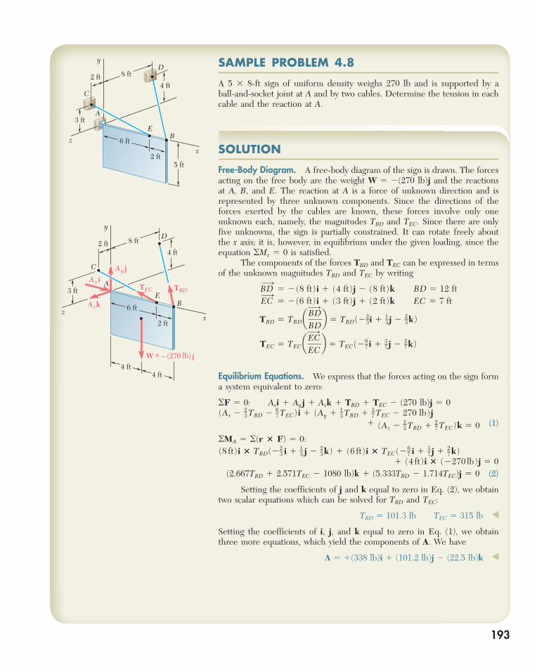
SAMPLE PROBLEM 4.8
A 5 3 8-ft sign of uniform density weighs 270 lb and is supported by a ball-and-socket joint at A and by two cables. Determine the tension in each cable and the reaction at A.
193
W = – (270 lb) j
A x i
Azk
A y j
TEC TBDA
B
C
D
E
x
y
z 6 ft
2 ft
2 ft4 ft
4 ft4 ft
8 ft
3 ft
SOLUTION
Free-Body Diagram. A free-body diagram of the sign is drawn. The forces acting on the free body are the weight W 5 2(270 lb)j and the reactions at A, B, and E. The reaction at A is a force of unknown direction and is represented by three unknown components. Since the directions of the forces exerted by the cables are known, these forces involve only one unknown each, namely, the magnitudes TBD and TEC. Since there are only five unknowns, the sign is partially constrained. It can rotate freely about the x axis; it is, however, in equilibrium under the given loading, since the equation oMx 5 0 is satisfied. The components of the forces TBD and TEC can be expressed in terms of the unknown magnitudes TBD and TEC by writing
BD¡
5 2(8 ft)i 1 (4 ft)j 2 (8 ft)k BD 5 12 ft EC¡
5 2(6 ft)i 1 (3 ft)j 1 (2 ft)k EC 5 7 ft
TBD 5 TBDaBD¡
BDb 5 TBD(22
3i 1 13 j 2 2
3k)
TEC 5 TECaEC¡
ECb 5 TEC(26
7 i 1 37 j 2 2
7k)
Equilibrium Equations. We express that the forces acting on the sign form a system equivalent to zero:
oF 5 0: Axi 1 Ayj 1 Azk 1 TBD 1 TEC 2 (270 lb)j 5 0(Ax 2 2
3 TBD 2 67 TEC)i 1 (Ay 1 1
3 TBD 1 37 TEC 2 270 lb)j
1 (Az 2 23 TBD 1 2
7 TEC)k 5 0 (1)
oMA 5 o(r 3 F) 5 0:(8 ft)i 3 TBD(22
3 i 1 1
3 j 2 2
3 k) 1 (6 ft)i 3 TEC(26
7 i 1 3
7 j 1 2
7 k)
1 (4 ft)i 3 (2270 lb)j 5 0(2.667TBD 1 2.571TEC 2 1080 lb)k 1 (5.333TBD 2 1.714TEC)j 5 0 (2)
Setting the coefficients of j and k equal to zero in Eq. (2), we obtain two scalar equations which can be solved for TBD and TEC:
TBD 5 101.3 lb TEC 5 315 lb ◀
Setting the coefficients of i, j, and k equal to zero in Eq. (1), we obtain three more equations, which yield the components of A. We have
A 5 1(338 lb)i 1 (101.2 lb)j 2 (22.5 lb)k ◀
A
B
C
D
E
x
y
z 6 ft
2 ft
2 ft
5 ft
4 ft
8 ft
3 ft
bee29400_ch04_156-217.indd Page 193 11/29/08 3:33:55 PM user-s172bee29400_ch04_156-217.indd Page 193 11/29/08 3:33:55 PM user-s172 /Volumes/204/MHDQ076/work%0/indd%0/Volumes/204/MHDQ076/work%0/indd%0
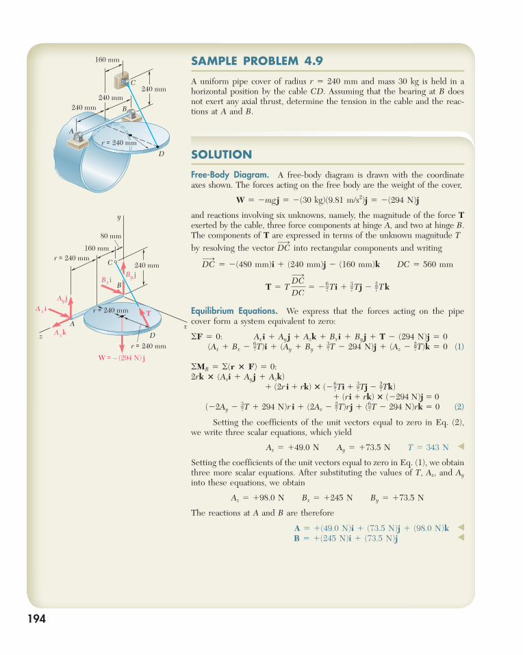
SAMPLE PROBLEM 4.9
A uniform pipe cover of radius r 5 240 mm and mass 30 kg is held in a horizontal position by the cable CD. Assuming that the bearing at B does not exert any axial thrust, determine the tension in the cable and the reac-tions at A and B.
194
r = 240 mm
A
B
C
D
W = – (294 N) j
Bx iBy j
A x iAyj
Azk
160 mm
80 mm
Tr = 240 mm
r = 240 mm
x
y
z
240 mm
r = 240 mm
A
B
C
D
160 mm
240 mm240 mm
240 mm
SOLUTION
Free-Body Diagram. A free-body diagram is drawn with the coordinate axes shown. The forces acting on the free body are the weight of the cover,
W 5 2mg j 5 2(30 kg)(9.81 m/s2)j 5 2(294 N)j
and reactions involving six unknowns, namely, the magnitude of the force T exerted by the cable, three force components at hinge A, and two at hinge B. The components of T are expressed in terms of the unknown magnitude T by resolving the vector DC
¡ into rectangular components and writing
DC¡
5 2(480 mm)i 1 (240 mm)j 2 (160 mm)k DC 5 560 mm
T 5 T DC¡
DC5 26
7 Ti 1 3
7 Tj 2 2
7 T k
Equilibrium Equations. We express that the forces acting on the pipe cover form a system equivalent to zero:
oF 5 0: Axi 1 Ay j 1 Azk 1 Bxi 1 Byj 1 T 2 (294 N)j 5 0 (Ax 1 Bx 2 6
7T)i 1 (Ay 1 By 1 37T 2 294 N)j 1 (Az 2 2
7T)k 5 0 (1)
oMB 5 o(r 3 F) 5 0:2rk 3 (Axi 1 Ayj 1 Azk) 1 (2r i 1 rk) 3 (2 67Ti 1 37Tj 2 27Tk) 1 (ri 1 rk) 3 (2294 N)j 5 0 (22Ay 2 3
7T 1 294 N)r i 1 (2Ax 2 27T)rj 1 (6
7T 2 294 N)rk 5 0 (2)
Setting the coefficients of the unit vectors equal to zero in Eq. (2), we write three scalar equations, which yield
Ax 5 149.0 N Ay 5 173.5 N T 5 343 N ◀
Setting the coefficients of the unit vectors equal to zero in Eq. (1), we obtain three more scalar equations. After substituting the values of T, Ax, and Ay into these equations, we obtain
Az 5 198.0 N Bx 5 1245 N By 5 173.5 N
The reactions at A and B are therefore
A 5 1(49.0 N)i 1 (73.5 N)j 1 (98.0 N)k ◀
B 5 1(245 N)i 1 (73.5 N)j ◀
bee29400_ch04_156-217.indd Page 194 11/29/08 3:33:56 PM user-s172bee29400_ch04_156-217.indd Page 194 11/29/08 3:33:56 PM user-s172 /Volumes/204/MHDQ076/work%0/indd%0/Volumes/204/MHDQ076/work%0/indd%0
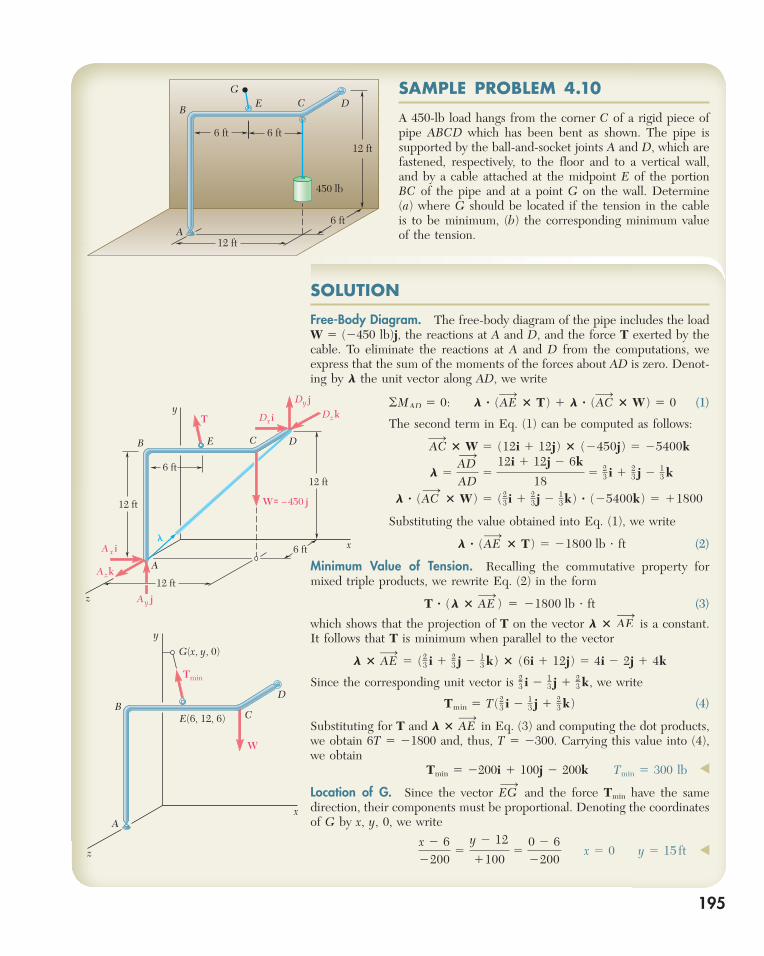
195
SAMPLE PROBLEM 4.10
A 450-lb load hangs from the corner C of a rigid piece of pipe ABCD which has been bent as shown. The pipe is supported by the ball-and-socket joints A and D, which are fastened, respectively, to the floor and to a vertical wall, and by a cable attached at the midpoint E of the portion BC of the pipe and at a point G on the wall. Determine (a) where G should be located if the tension in the cable is to be minimum, (b) the corresponding minimum value of the tension.
12 ft
12 ft
450 lb
A
BC DE
G
6 ft6 ft
6 ft
A
B C DE
x
y
z
T
�
Dxi
Dy jDzk
A x i
Ay j
Azk
W = –450 j
6 ft
6 ft
12 ft
12 ft
12 ft
A
BC
D
G(x, y, 0)
E(6, 12, 6)
x
y
z
W
Tmin
SOLUTION
Free-Body Diagram. The free-body diagram of the pipe includes the load W 5 (2450 lb)j, the reactions at A and D, and the force T exerted by the cable. To eliminate the reactions at A and D from the computations, we express that the sum of the moments of the forces about AD is zero. Denot-ing by l the unit vector along AD, we write
oMAD 5 0: L ? (AE¡
3 T) 1 L ? (AC¡
3 W) 5 0 (1)
The second term in Eq. (1) can be computed as follows:
AC¡
3 W 5 (12i 1 12j) 3 (2450j) 5 25400k
L 5AD¡
AD5
12i 1 12j 2 6k
185 2
3 i 1 23 j 2 1
3 k
L ? (AC¡
3 W) 5 (23 i 1 2
3 j 2 1
3 k) ? (25400k) 5 11800
Substituting the value obtained into Eq. (1), we write
L ? (AE¡
3 T) 5 21800 lb ? ft (2)
Minimum Value of Tension. Recalling the commutative property for mixed triple products, we rewrite Eq. (2) in the form
T ? (L 3 AE¡
) 5 21800 lb ? ft (3)
which shows that the projection of T on the vector L 3 AE¡
is a constant. It follows that T is minimum when parallel to the vector
L 3 AE¡
5 (23 i 1 2
3 j 2 13 k) 3 (6i 1 12j) 5 4i 2 2j 1 4k
Since the corresponding unit vector is 23 i 2 1
3 j 1 23 k, we write
Tmin 5 T(23 i 2 1
3 j 1 23 k) (4)
Substituting for T and L 3 AE¡
in Eq. (3) and computing the dot products, we obtain 6T 5 21800 and, thus, T 5 2300. Carrying this value into (4), we obtain
Tmin 5 2200i 1 100j 2 200k Tmin 5 300 lb ◀
Location of G. Since the vector EG¡
and the force Tmin have the same direction, their components must be proportional. Denoting the coordinates of G by x, y, 0, we write
x 2 62200
5y 2 12
11005
0 2 62200
x 5 0 y 5 15 ft ◀
bee29400_ch04_156-217.indd Page 195 11/29/08 3:33:57 PM user-s172bee29400_ch04_156-217.indd Page 195 11/29/08 3:33:57 PM user-s172 /Volumes/204/MHDQ076/work%0/indd%0/Volumes/204/MHDQ076/work%0/indd%0
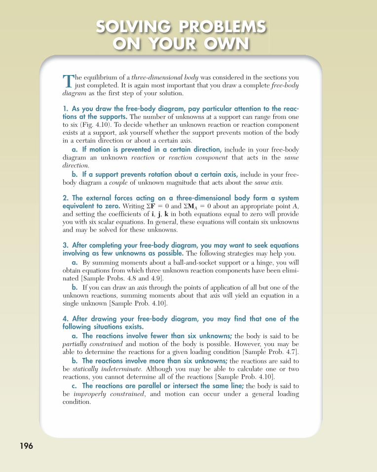
196
The equilibrium of a three-dimensional body was considered in the sections you just completed. It is again most important that you draw a complete free-body
diagram as the first step of your solution.
1. As you draw the free-body diagram, pay particular attention to the reac-tions at the supports. The number of unknowns at a support can range from one to six (Fig. 4.10). To decide whether an unknown reaction or reaction component exists at a support, ask yourself whether the support prevents motion of the body in a certain direction or about a certain axis. a. If motion is prevented in a certain direction, include in your free-body diagram an unknown reaction or reaction component that acts in the same direction. b. If a support prevents rotation about a certain axis, include in your free-body diagram a couple of unknown magnitude that acts about the same axis.
2. The external forces acting on a three-dimensional body form a system equivalent to zero. Writing oF 5 0 and oMA 5 0 about an appropriate point A, and setting the coefficients of i, j, k in both equations equal to zero will provide you with six scalar equations. In general, these equations will contain six unknowns and may be solved for these unknowns.
3. After completing your free-body diagram, you may want to seek equations involving as few unknowns as possible. The following strategies may help you. a. By summing moments about a ball-and-socket support or a hinge, you will obtain equations from which three unknown reaction components have been elimi-nated [Sample Probs. 4.8 and 4.9]. b. If you can draw an axis through the points of application of all but one of the unknown reactions, summing moments about that axis will yield an equation in a single unknown [Sample Prob. 4.10].
4. After drawing your free-body diagram, you may find that one of the following situations exists. a. The reactions involve fewer than six unknowns; the body is said to be partially constrained and motion of the body is possible. However, you may be able to determine the reactions for a given loading condition [Sample Prob. 4.7]. b. The reactions involve more than six unknowns; the reactions are said to be statically indeterminate. Although you may be able to calculate one or two reactions, you cannot determine all of the reactions [Sample Prob. 4.10]. c. The reactions are parallel or intersect the same line; the body is said to be improperly constrained, and motion can occur under a general loading condition.
SOLVING PROBLEMSON YOUR OWN
bee29400_ch04_156-217.indd Page 196 11/29/08 3:33:58 PM user-s172bee29400_ch04_156-217.indd Page 196 11/29/08 3:33:58 PM user-s172 /Volumes/204/MHDQ076/work%0/indd%0/Volumes/204/MHDQ076/work%0/indd%0
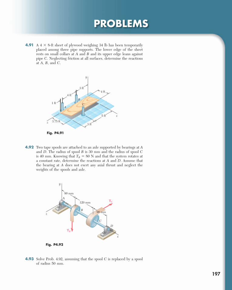
PROBLEMS
197
4.91 A 4 3 8-ft sheet of plywood weighing 34 lb has been temporarily placed among three pipe supports. The lower edge of the sheet rests on small collars at A and B and its upper edge leans against pipe C. Neglecting friction at all surfaces, determine the reactions at A, B, and C.
4 ft
y
z
B
A
x
1 ft
3.75 ft3 ft
5 ft
3 ft
4 ft
C
Fig. P4.91
TB
x
D
C
B
A
z
y
90 mm
90 mm
120 mm TC
Fig. P4.92
4.92 Two tape spools are attached to an axle supported by bearings at Aand D. The radius of spool B is 30 mm and the radius of spool Cis 40 mm. Knowing that TB 5 80 N and that the system rotates at a constant rate, determine the reactions at A and D. Assume that the bearing at A does not exert any axial thrust and neglect the weights of the spools and axle.
4.93 Solve Prob. 4.92, assuming that the spool C is replaced by a spool of radius 50 mm.
bee29400_ch04_156-217.indd Page 197 11/29/08 3:34:00 PM user-s172bee29400_ch04_156-217.indd Page 197 11/29/08 3:34:00 PM user-s172 /Volumes/204/MHDQ076/work%0/indd%0/Volumes/204/MHDQ076/work%0/indd%0
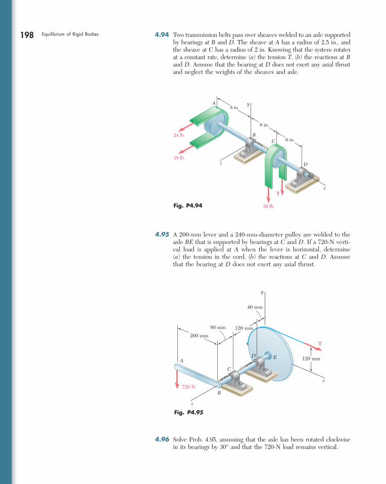
198 Equilibrium of Rigid Bodies 4.94 Two transmission belts pass over sheaves welded to an axle supported by bearings at B and D. The sheave at A has a radius of 2.5 in., and the sheave at C has a radius of 2 in. Knowing that the system rotates at a constant rate, determine (a) the tension T, (b) the reactions at B and D. Assume that the bearing at D does not exert any axial thrust and neglect the weights of the sheaves and axle.
T
720 N
y
80 mm 120 mm
120 mm
200 mm
AE
B
C
D
x
z
40 mm
Fig. P4.95
4.95 A 200-mm lever and a 240-mm-diameter pulley are welded to the axle BE that is supported by bearings at C and D. If a 720-N verti-cal load is applied at A when the lever is horizontal, determine (a) the tension in the cord, (b) the reactions at C and D. Assume that the bearing at D does not exert any axial thrust.
30 lb
T
24 lb
18 lb
y8 in.
6 in.
A
BC
D
x
z
6 in.
Fig. P4.94
4.96 Solve Prob. 4.95, assuming that the axle has been rotated clockwise in its bearings by 30° and that the 720-N load remains vertical.
bee29400_ch04_156-217.indd Page 198 11/29/08 3:34:02 PM user-s172bee29400_ch04_156-217.indd Page 198 11/29/08 3:34:02 PM user-s172 /Volumes/204/MHDQ076/work%0/indd%0/Volumes/204/MHDQ076/work%0/indd%0
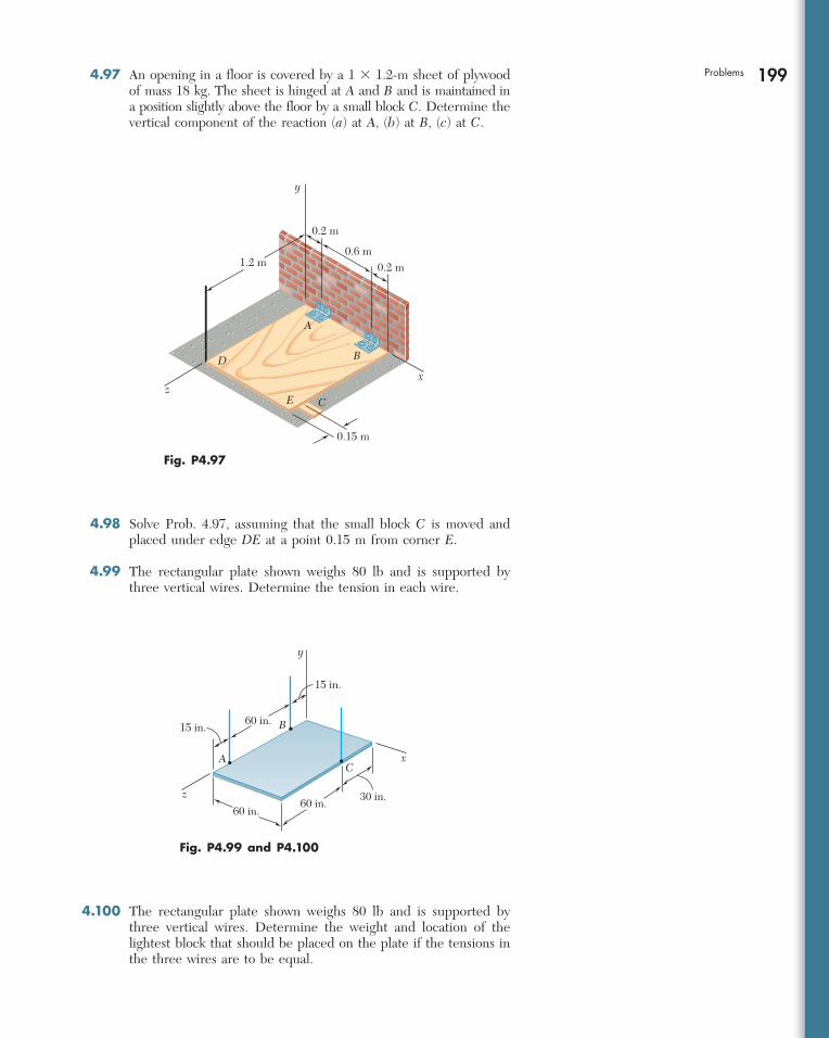
199Problems 4.97 An opening in a floor is covered by a 1 3 1.2-m sheet of plywood of mass 18 kg. The sheet is hinged at A and B and is maintained in a position slightly above the floor by a small block C. Determine the vertical component of the reaction (a) at A, (b) at B, (c) at C.
y
zx
A
B
E C
0.15 m
0.2 m
0.2 m0.6 m
1.2 m
D
Fig. P4.97
xC
A
60 in.
60 in.60 in. 30 in.
15 in.
15 in.
B
z
y
Fig. P4.99 and P4.100
4.98 Solve Prob. 4.97, assuming that the small block C is moved and placed under edge DE at a point 0.15 m from corner E.
4.99 The rectangular plate shown weighs 80 lb and is supported by three vertical wires. Determine the tension in each wire.
4.100 The rectangular plate shown weighs 80 lb and is supported by three vertical wires. Determine the weight and location of the lightest block that should be placed on the plate if the tensions in the three wires are to be equal.
bee29400_ch04_156-217.indd Page 199 11/29/08 3:34:02 PM user-s172bee29400_ch04_156-217.indd Page 199 11/29/08 3:34:02 PM user-s172 /Volumes/204/MHDQ076/work%0/indd%0/Volumes/204/MHDQ076/work%0/indd%0
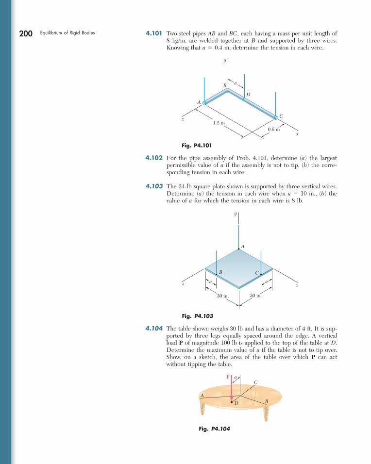
200 Equilibrium of Rigid Bodies 4.101 Two steel pipes AB and BC, each having a mass per unit length of 8 kg/m, are welded together at B and supported by three wires. Knowing that a 5 0.4 m, determine the tension in each wire.
4.102 For the pipe assembly of Prob. 4.101, determine (a) the largest permissible value of a if the assembly is not to tip, (b) the corre-sponding tension in each wire.
4.103 The 24-lb square plate shown is supported by three vertical wires. Determine (a) the tension in each wire when a 5 10 in., (b) the value of a for which the tension in each wire is 8 lb.
4.104 The table shown weighs 30 lb and has a diameter of 4 ft. It is sup-ported by three legs equally spaced around the edge. A vertical load P of magnitude 100 lb is applied to the top of the table at D. Determine the maximum value of a if the table is not to tip over. Show, on a sketch, the area of the table over which P can act without tipping the table.
B
A
C
D
y
x
z
a
1.2 m0.6 m
Fig. P4.101
y
x
B C
A
a
30 in.
a
30 in.
z
Fig. P4.103
AB
C
D
aP
Fig. P4.104
bee29400_ch04_156-217.indd Page 200 11/29/08 3:34:03 PM user-s172bee29400_ch04_156-217.indd Page 200 11/29/08 3:34:03 PM user-s172 /Volumes/204/MHDQ076/work%0/indd%0/Volumes/204/MHDQ076/work%0/indd%0
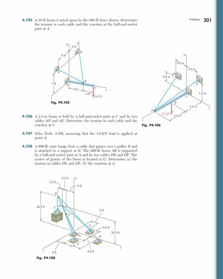
201Problems 4.105 A 10-ft boom is acted upon by the 840-lb force shown. Determine the tension in each cable and the reaction at the ball-and-socket joint at A.
x
y
E
G
A
B
C D22.5 ft
16.5 ft
5 ft
6.6 ft5 ft
13 ft
6 ft
2.8 ft3.2 ft
F
H
z
6.6 ft
Fig. P4.108
4.106 A 2.4-m boom is held by a ball-and-socket joint at C and by two cables AD and AE. Determine the tension in each cable and the reaction at C.
4.107 Solve Prob. 4.106, assuming that the 3.6-kN load is applied at point A.
4.108 A 600-lb crate hangs from a cable that passes over a pulley B and is attached to a support at H. The 200-lb boom AB is supported by a ball-and-socket joint at A and by two cables DE and DF. The center of gravity of the boom is located at G. Determine (a) the tension in cables DE and DF, (b) the reaction at A.
840 lb
x
y
z
E
AB
C
D
4 ft6 ft
7 ft
6 ft
6 ft
Fig. P4.105
A
B
C
x
y
z
D
E
3.6 kN
1.2 m
1.2 m
1.2 m
0.6 m
0.8 m
0.8 m
Fig. P4.106
bee29400_ch04_156-217.indd Page 201 11/29/08 3:34:03 PM user-s172bee29400_ch04_156-217.indd Page 201 11/29/08 3:34:03 PM user-s172 /Volumes/204/MHDQ076/work%0/indd%0/Volumes/204/MHDQ076/work%0/indd%0
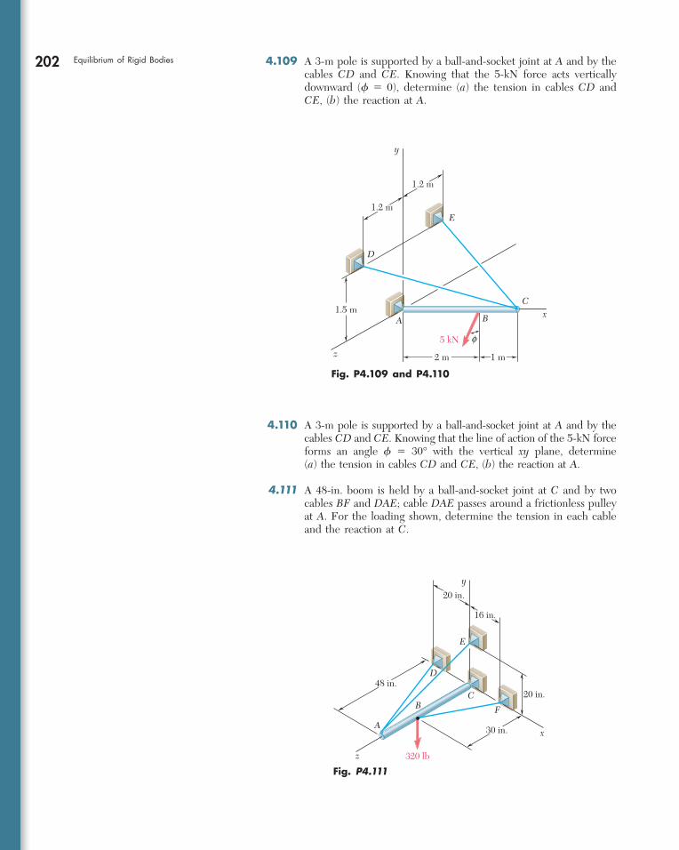
202 Equilibrium of Rigid Bodies 4.109 A 3-m pole is supported by a ball-and-socket joint at A and by the cables CD and CE. Knowing that the 5-kN force acts vertically downward (f 5 0), determine (a) the tension in cables CD and CE, (b) the reaction at A.
x
y
z
E
D
C
A1.5 m
2 m 1 m
1.2 m
1.2 m
B
5 kN f
Fig. P4.109 and P4.110
4.110 A 3-m pole is supported by a ball-and-socket joint at A and by the cables CD and CE. Knowing that the line of action of the 5-kN force forms an angle f 5 30° with the vertical xy plane, determine (a) the tension in cables CD and CE, (b) the reaction at A.
4.111 A 48-in. boom is held by a ball-and-socket joint at C and by two cables BF and DAE; cable DAE passes around a frictionless pulley at A. For the loading shown, determine the tension in each cable and the reaction at C.
A
BC
F
x
y
z
D
E
20 in.
16 in.
320 lb
30 in.
20 in.
48 in.
Fig. P4.111
bee29400_ch04_156-217.indd Page 202 11/29/08 3:34:04 PM user-s172bee29400_ch04_156-217.indd Page 202 11/29/08 3:34:04 PM user-s172 /Volumes/204/MHDQ076/work%0/indd%0/Volumes/204/MHDQ076/work%0/indd%0
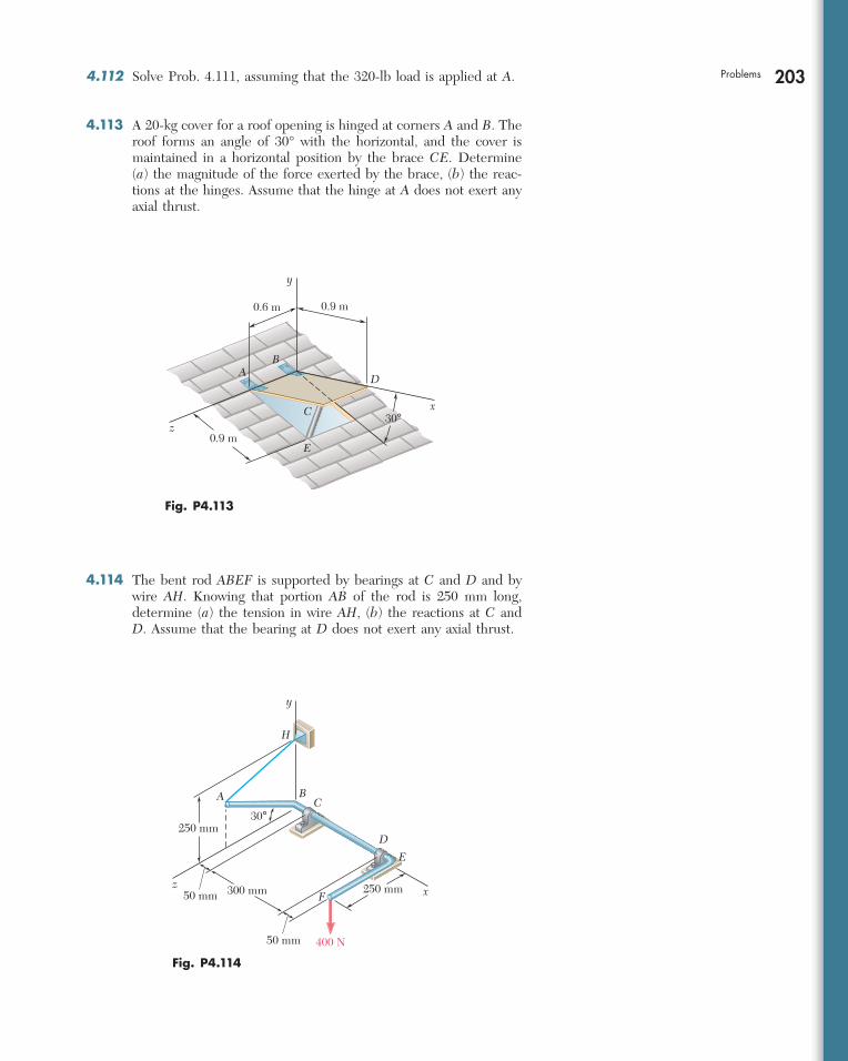
203Problems 4.112 Solve Prob. 4.111, assuming that the 320-lb load is applied at A.
4.113 A 20-kg cover for a roof opening is hinged at corners A and B. The roof forms an angle of 30° with the horizontal, and the cover is maintained in a horizontal position by the brace CE. Determine (a) the magnitude of the force exerted by the brace, (b) the reac-tions at the hinges. Assume that the hinge at A does not exert any axial thrust.
4.114 The bent rod ABEF is supported by bearings at C and D and by wire AH. Knowing that portion AB of the rod is 250 mm long, determine (a) the tension in wire AH, (b) the reactions at C and D. Assume that the bearing at D does not exert any axial thrust.
250 mm50 mm 300 mm
400 N
C
D
E
F xz
50 mm
250 mm
A B
H
y
30°
Fig. P4.114
E
C
D
z
A
y
x
B
0.9 m
0.9 m0.6 m
30°
Fig. P4.113
bee29400_ch04_156-217.indd Page 203 11/29/08 3:34:04 PM user-s172bee29400_ch04_156-217.indd Page 203 11/29/08 3:34:04 PM user-s172 /Volumes/204/MHDQ076/work%0/indd%0/Volumes/204/MHDQ076/work%0/indd%0
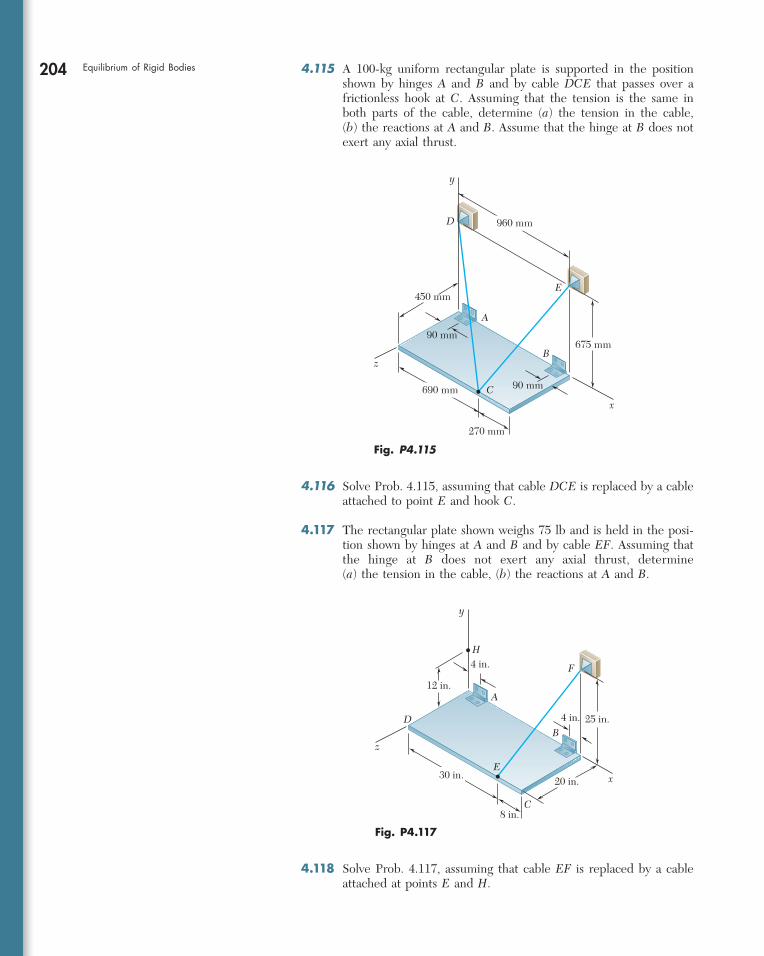
204 Equilibrium of Rigid Bodies
4.116 Solve Prob. 4.115, assuming that cable DCE is replaced by a cable attached to point E and hook C.
4.117 The rectangular plate shown weighs 75 lb and is held in the posi-tion shown by hinges at A and B and by cable EF. Assuming that the hinge at B does not exert any axial thrust, determine (a) the tension in the cable, (b) the reactions at A and B.
x
y
z
D
H
F
E
A
B
C
25 in.
20 in.
4 in.
12 in.
8 in.
4 in.
30 in.
Fig. P4.117
4.115 A 100-kg uniform rectangular plate is supported in the position shown by hinges A and B and by cable DCE that passes over a frictionless hook at C. Assuming that the tension is the same in both parts of the cable, determine (a) the tension in the cable, (b) the reactions at A and B. Assume that the hinge at B does not exert any axial thrust.
690 mm
960 mm
x
y
z
E
D
A
B
C
675 mm90 mm
450 mm
270 mm
90 mm
Fig. P4.115
4.118 Solve Prob. 4.117, assuming that cable EF is replaced by a cable attached at points E and H.
bee29400_ch04_156-217.indd Page 204 11/29/08 3:34:05 PM user-s172bee29400_ch04_156-217.indd Page 204 11/29/08 3:34:05 PM user-s172 /Volumes/204/MHDQ076/work%0/indd%0/Volumes/204/MHDQ076/work%0/indd%0
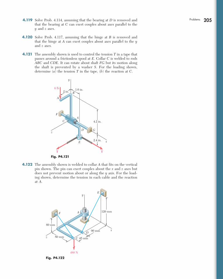
205Problems 4.119 Solve Prob. 4.114, assuming that the bearing at D is removed and that the bearing at C can exert couples about axes parallel to the y and z axes.
4.120 Solve Prob. 4.117, assuming that the hinge at B is removed and that the hinge at A can exert couples about axes parallel to the y and z axes.
4.121 The assembly shown is used to control the tension T in a tape that passes around a frictionless spool at E. Collar C is welded to rods ABC and CDE. It can rotate about shaft FG but its motion along the shaft is prevented by a washer S. For the loading shown, determine (a) the tension T in the tape, (b) the reaction at C.
4.122 The assembly shown is welded to collar A that fits on the vertical pin shown. The pin can exert couples about the x and z axes but does not prevent motion about or along the y axis. For the load-ing shown, determine the tension in each cable and the reaction at A.
T
A
B
C
F
D
E
S
G
x
y
z
6 lb2 in.
1.6 in.
4.2 in.
2.4 in.
T
Fig. P4.121
480 N
A
C
D
E
F
x
y
z
60 mm
45 mm
90 mm
120 mm
80 mm
Fig. P4.122
bee29400_ch04_156-217.indd Page 205 11/29/08 3:34:05 PM user-s172bee29400_ch04_156-217.indd Page 205 11/29/08 3:34:05 PM user-s172 /Volumes/204/MHDQ076/work%0/indd%0/Volumes/204/MHDQ076/work%0/indd%0
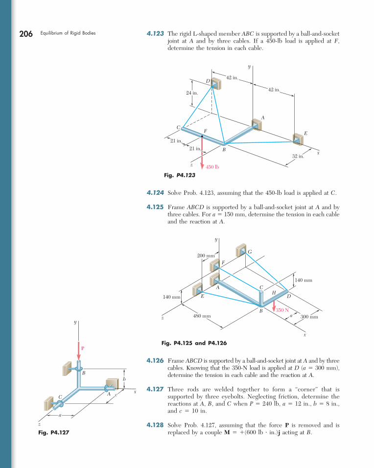
206 Equilibrium of Rigid Bodies 4.123 The rigid L-shaped member ABC is supported by a ball-and-socket joint at A and by three cables. If a 450-lb load is applied at F, determine the tension in each cable.
x
z
y
A
B
C
D
EF
450 lb
24 in.
32 in.21 in.
21 in.
42 in.
42 in.
Fig. P4.123
4.124 Solve Prob. 4.123, assuming that the 450-lb load is applied at C.
4.125 Frame ABCD is supported by a ball-and-socket joint at A and by three cables. For a 5 150 mm, determine the tension in each cable and the reaction at A.
4.126 Frame ABCD is supported by a ball-and-socket joint at A and by three cables. Knowing that the 350-N load is applied at D (a 5 300 mm), determine the tension in each cable and the reaction at A.
4.127 Three rods are welded together to form a “corner” that is supported by three eyebolts. Neglecting friction, determine the reactions at A, B, and C when P 5 240 lb, a 5 12 in., b 5 8 in., and c 5 10 in.
4.128 Solve Prob. 4.127, assuming that the force P is removed and is replaced by a couple M 5 1(600 lb ? in.)j acting at B.
A
B
CH
DE
F
G
x
y
z
140 mm
350 N300 mm
140 mm
200 mm
a480 mm
Fig. P4.125 and P4.126
x
y
z
b
cA
B
C
P
a
Fig. P4.127
bee29400_ch04_156-217.indd Page 206 11/29/08 3:34:05 PM user-s172bee29400_ch04_156-217.indd Page 206 11/29/08 3:34:05 PM user-s172 /Volumes/204/MHDQ076/work%0/indd%0/Volumes/204/MHDQ076/work%0/indd%0
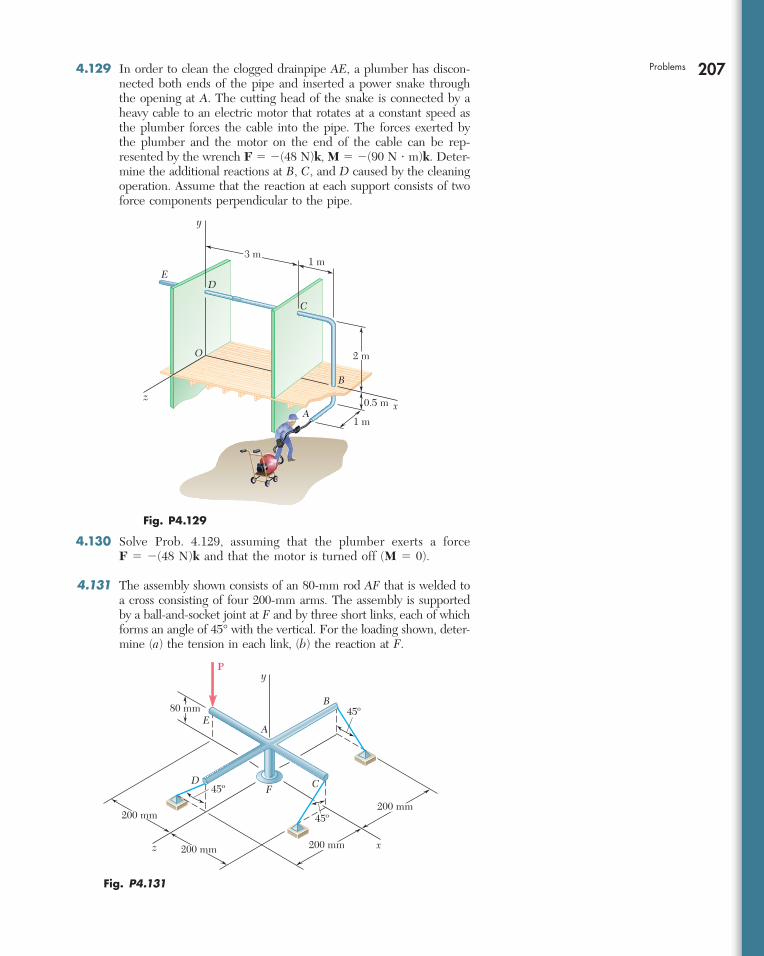
207Problems 4.129 In order to clean the clogged drainpipe AE, a plumber has discon-nected both ends of the pipe and inserted a power snake through the opening at A. The cutting head of the snake is connected by a heavy cable to an electric motor that rotates at a constant speed as the plumber forces the cable into the pipe. The forces exerted by the plumber and the motor on the end of the cable can be rep-resented by the wrench F 5 2(48 N)k, M 5 2(90 N ? m)k. Deter-mine the additional reactions at B, C, and D caused by the cleaning operation. Assume that the reaction at each support consists of two force components perpendicular to the pipe.
0.5 m x
y
z
A
B
DE
O
3 m1 m
2 m
1 m
C
Fig. P4.129
4.130 Solve Prob. 4.129, assuming that the plumber exerts a force F 5 2(48 N)k and that the motor is turned off (M 5 0).
4.131 The assembly shown consists of an 80-mm rod AF that is welded to a cross consisting of four 200-mm arms. The assembly is supported by a ball-and-socket joint at F and by three short links, each of which forms an angle of 45° with the vertical. For the loading shown, deter-mine (a) the tension in each link, (b) the reaction at F.
x
y
z
E
F
A
B
P
CD
45º
45º
45º
200 mm 200 mm
200 mm200 mm
80 mm
Fig. P4.131
bee29400_ch04_156-217.indd Page 207 11/29/08 3:34:06 PM user-s172bee29400_ch04_156-217.indd Page 207 11/29/08 3:34:06 PM user-s172 /Volumes/204/MHDQ076/work%0/indd%0/Volumes/204/MHDQ076/work%0/indd%0
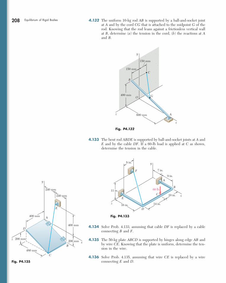
208 Equilibrium of Rigid Bodies 4.132 The uniform 10-kg rod AB is supported by a ball-and-socket joint at A and by the cord CG that is attached to the midpoint G of the rod. Knowing that the rod leans against a frictionless vertical wall at B, determine (a) the tension in the cord, (b) the reactions at A and B.
x
y
z
GO
A
B
C150 mm
150 mm
400 mm
600 mm
Fig. P4.132
x
y
z
A
B
C
D
E
F
8 in.
7 in.
9 in.
60 lb11 in.
16 in.
10 in.
14 in.
Fig. P4.133
x
y
z
A
B
C
D
E
240 mm
400 mm
400 mm
200 mm200 mm
480 mm
240 mm
Fig. P4.135
4.133 The bent rod ABDE is supported by ball-and-socket joints at A and E and by the cable DF. If a 60-lb load is applied at C as shown, determine the tension in the cable.
4.134 Solve Prob. 4.133, assuming that cable DF is replaced by a cable connecting B and F.
4.135 The 50-kg plate ABCD is supported by hinges along edge AB and by wire CE. Knowing that the plate is uniform, determine the ten-sion in the wire.
4.136 Solve Prob. 4.135, assuming that wire CE is replaced by a wire connecting E and D.
bee29400_ch04_156-217.indd Page 208 11/29/08 3:34:07 PM user-s172bee29400_ch04_156-217.indd Page 208 11/29/08 3:34:07 PM user-s172 /Volumes/204/MHDQ076/work%0/indd%0/Volumes/204/MHDQ076/work%0/indd%0
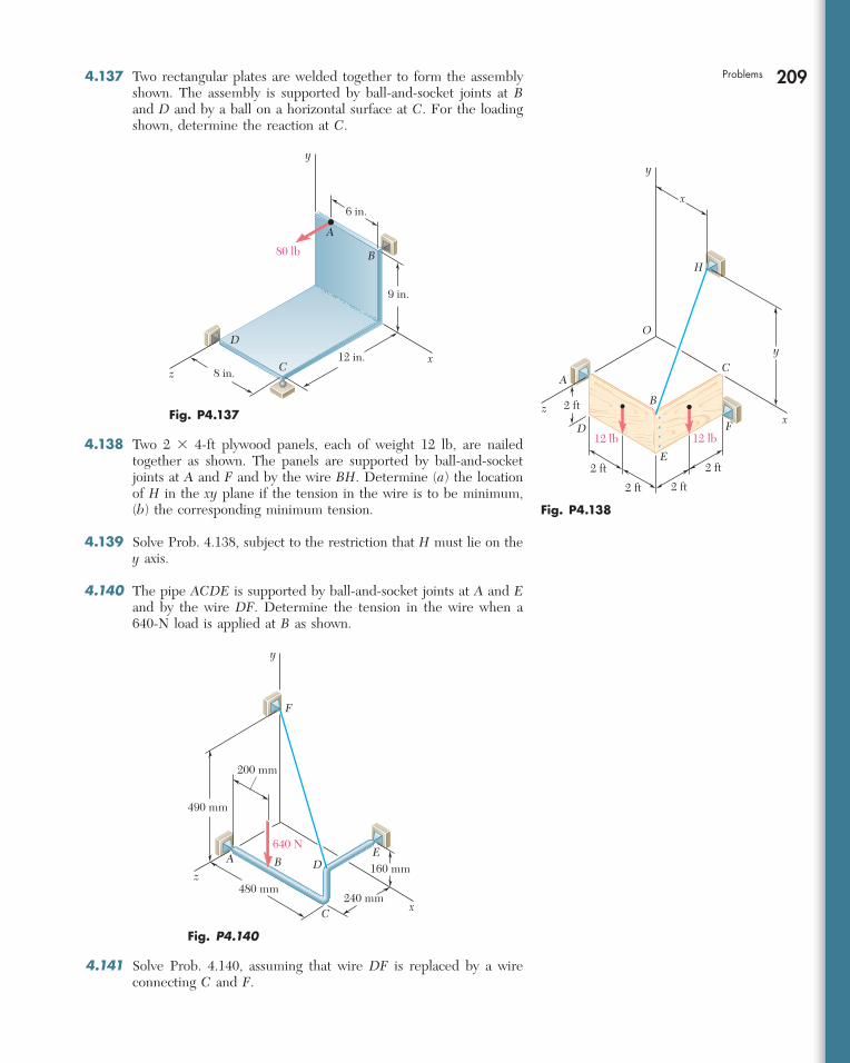
209Problems 4.137 Two rectangular plates are welded together to form the assembly shown. The assembly is supported by ball-and-socket joints at B and D and by a ball on a horizontal surface at C. For the loading shown, determine the reaction at C.
B
A
y
z
D
Cx
6 in.
12 in.8 in.
9 in.
80 lb
Fig. P4.137 z 2 ft
2 ft
2 ft
2 ft
2 ft
x
x
y
y
A
B
C
O
H
D
E
F12 lb12 lb
Fig. P4.138
640 N
x
y
z
A B
C
DE
F
240 mm
160 mm
480 mm
200 mm
490 mm
Fig. P4.140
4.138 Two 2 3 4-ft plywood panels, each of weight 12 lb, are nailed together as shown. The panels are supported by ball-and-socket joints at A and F and by the wire BH. Determine (a) the location of H in the xy plane if the tension in the wire is to be minimum, (b) the corresponding minimum tension.
4.139 Solve Prob. 4.138, subject to the restriction that H must lie on the y axis.
4.140 The pipe ACDE is supported by ball-and-socket joints at A and E and by the wire DF. Determine the tension in the wire when a 640-N load is applied at B as shown.
4.141 Solve Prob. 4.140, assuming that wire DF is replaced by a wire connecting C and F.
bee29400_ch04_156-217.indd Page 209 11/29/08 3:34:07 PM user-s172bee29400_ch04_156-217.indd Page 209 11/29/08 3:34:07 PM user-s172 /Volumes/204/MHDQ076/work%0/indd%0/Volumes/204/MHDQ076/work%0/indd%0
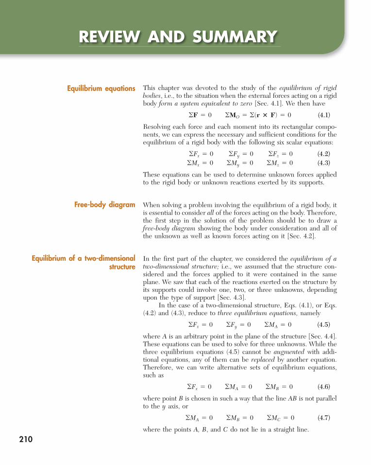
210
REVIEW AND SUMMARY
This chapter was devoted to the study of the equilibrium of rigid bodies, i.e., to the situation when the external forces acting on a rigid body form a system equivalent to zero [Sec. 4.1]. We then have
oF 5 0 oMO 5 o(r 3 F) 5 0 (4.1)
Resolving each force and each moment into its rectangular compo-nents, we can express the necessary and sufficient conditions for the equilibrium of a rigid body with the following six scalar equations:
oFx 5 0 oFy 5 0 oFz 5 0 (4.2)oMx 5 0 oMy 5 0 oMz 5 0 (4.3)
These equations can be used to determine unknown forces applied to the rigid body or unknown reactions exerted by its supports.
When solving a problem involving the equilibrium of a rigid body, it is essential to consider all of the forces acting on the body. Therefore, the first step in the solution of the problem should be to draw a free-body diagram showing the body under consideration and all of the unknown as well as known forces acting on it [Sec. 4.2].
In the first part of the chapter, we considered the equilibrium of a two-dimensional structure; i.e., we assumed that the structure con-sidered and the forces applied to it were contained in the same plane. We saw that each of the reactions exerted on the structure by its supports could involve one, two, or three unknowns, depending upon the type of support [Sec. 4.3]. In the case of a two-dimensional structure, Eqs. (4.1), or Eqs. (4.2) and (4.3), reduce to three equilibrium equations, namely
oFx 5 0 oFy 5 0 oMA 5 0 (4.5)
where A is an arbitrary point in the plane of the structure [Sec. 4.4]. These equations can be used to solve for three unknowns. While the three equilibrium equations (4.5) cannot be augmented with addi-tional equations, any of them can be replaced by another equation. Therefore, we can write alternative sets of equilibrium equations, such as
oFx 5 0 oMA 5 0 oMB 5 0 (4.6)
where point B is chosen in such a way that the line AB is not parallel to the y axis, or
oMA 5 0 oMB 5 0 oMC 5 0 (4.7)
where the points A, B, and C do not lie in a straight line.
Equilibrium equationsEquilibrium equations
Free-body diagramFree-body diagram
Equilibrium of a two-dimensional structure
Equilibrium of a two-dimensional structure
bee29400_ch04_156-217.indd Page 210 11/29/08 3:34:07 PM user-s172bee29400_ch04_156-217.indd Page 210 11/29/08 3:34:07 PM user-s172 /Volumes/204/MHDQ076/work%0/indd%0/Volumes/204/MHDQ076/work%0/indd%0
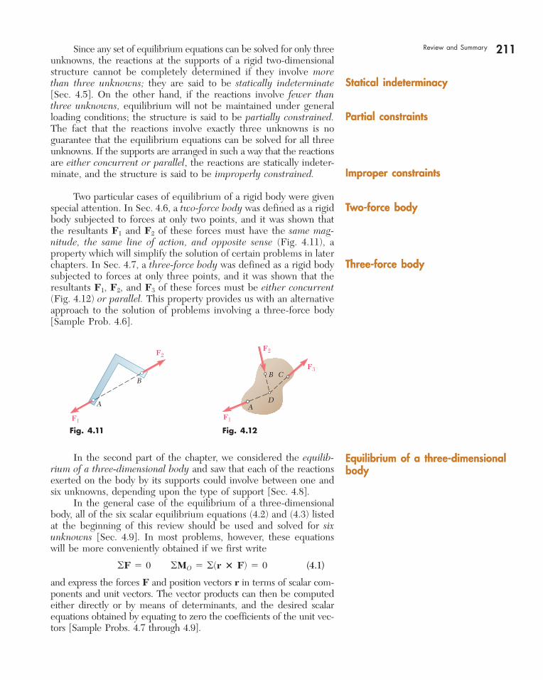
211 Since any set of equilibrium equations can be solved for only three unknowns, the reactions at the supports of a rigid two-dimensional structure cannot be completely determined if they involve more than three unknowns; they are said to be statically indeterminate [Sec. 4.5]. On the other hand, if the reactions involve fewer than three unknowns, equilibrium will not be maintained under general loading conditions; the structure is said to be partially constrained. The fact that the reactions involve exactly three unknowns is no guarantee that the equilibrium equations can be solved for all three unknowns. If the supports are arranged in such a way that the reactions are either concurrent or parallel, the reactions are statically indeter-minate, and the structure is said to be improperly constrained.
Two particular cases of equilibrium of a rigid body were given special attention. In Sec. 4.6, a two-force body was defined as a rigid body subjected to forces at only two points, and it was shown that the resultants F1 and F2 of these forces must have the same mag-nitude, the same line of action, and opposite sense (Fig. 4.11), a property which will simplify the solution of certain problems in later chapters. In Sec. 4.7, a three-force body was defined as a rigid body subjected to forces at only three points, and it was shown that the resultants F1, F2, and F3 of these forces must be either concurrent (Fig. 4.12) or parallel. This property provides us with an alternative approach to the solution of problems involving a three-force body [Sample Prob. 4.6].
Statical indeterminacyStatical indeterminacy
Partial constraintsPartial constraints
Improper constraintsImproper constraints
Two-force bodyTwo-force body
Three-force bodyThree-force body
A
B
F1
F2
Fig. 4.11
F2
F3
F1
B C
DA
Fig. 4.12
In the second part of the chapter, we considered the equilib-rium of a three-dimensional body and saw that each of the reactions exerted on the body by its supports could involve between one and six unknowns, depending upon the type of support [Sec. 4.8]. In the general case of the equilibrium of a three-dimensional body, all of the six scalar equilibrium equations (4.2) and (4.3) listed at the beginning of this review should be used and solved for six unknowns [Sec. 4.9]. In most problems, however, these equations will be more conveniently obtained if we first write
oF 5 0 oMO 5 o(r 3 F) 5 0 (4.1)
and express the forces F and position vectors r in terms of scalar com-ponents and unit vectors. The vector products can then be computed either directly or by means of determinants, and the desired scalar equations obtained by equating to zero the coefficients of the unit vec-tors [Sample Probs. 4.7 through 4.9].
Equilibrium of a three-dimensional bodyEquilibrium of a three-dimensional body
Review and Summary
bee29400_ch04_156-217.indd Page 211 11/29/08 3:34:09 PM user-s172bee29400_ch04_156-217.indd Page 211 11/29/08 3:34:09 PM user-s172 /Volumes/204/MHDQ076/work%0/indd%0/Volumes/204/MHDQ076/work%0/indd%0
212 Equilibrium of Rigid Bodies We noted that as many as three unknown reaction components may be eliminated from the computation of oMO in the second of the relations (4.1) through a judicious choice of point O. Also, the reactions at two points A and B can be eliminated from the solution of some problems by writing the equation oMAB 5 0, which involves the computation of the moments of the forces about an axis AB join-ing points A and B [Sample Prob. 4.10]. If the reactions involve more than six unknowns, some of the reactions are statically indeterminate; if they involve fewer than six unknowns, the rigid body is only partially constrained. Even with six or more unknowns, the rigid body will be improperly constrained if the reactions associated with the given supports either are parallel or intersect the same line.
bee29400_ch04_156-217.indd Page 212 11/29/08 3:34:09 PM user-s172bee29400_ch04_156-217.indd Page 212 11/29/08 3:34:09 PM user-s172 /Volumes/204/MHDQ076/work%0/indd%0/Volumes/204/MHDQ076/work%0/indd%0
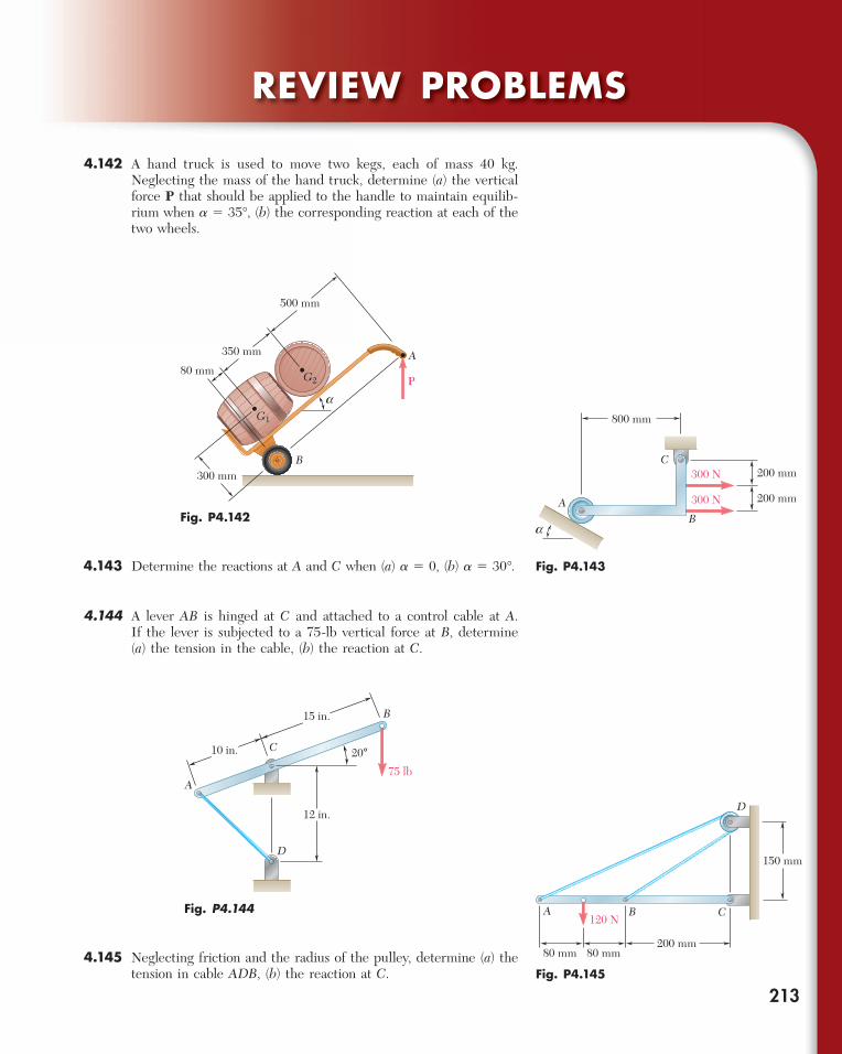
213
REVIEW PROBLEMS
4.142 A hand truck is used to move two kegs, each of mass 40 kg. Neglecting the mass of the hand truck, determine (a) the vertical force P that should be applied to the handle to maintain equilib-rium when a 5 35°, (b) the corresponding reaction at each of the two wheels.
A
P
B
G1
G280 mm
350 mm
300 mm
500 mm
a
Fig. P4.142
800 mm
200 mm300 N
200 mm300 N
a
AB
C
Fig. P4.143
A
B
D
12 in.
20°75 lb
C10 in.
15 in.
Fig. P4.144 A B C
150 mm
200 mm80 mm 80 mm
120 N
D
Fig. P4.145
4.143 Determine the reactions at A and C when (a) a 5 0, (b) a 5 30°.
4.144 A lever AB is hinged at C and attached to a control cable at A. If the lever is subjected to a 75-lb vertical force at B, determine (a) the tension in the cable, (b) the reaction at C.
4.145 Neglecting friction and the radius of the pulley, determine (a) the tension in cable ADB, (b) the reaction at C.
bee29400_ch04_156-217.indd Page 213 11/29/08 3:34:09 PM user-s172bee29400_ch04_156-217.indd Page 213 11/29/08 3:34:09 PM user-s172 /Volumes/204/MHDQ076/work%0/indd%0/Volumes/204/MHDQ076/work%0/indd%0
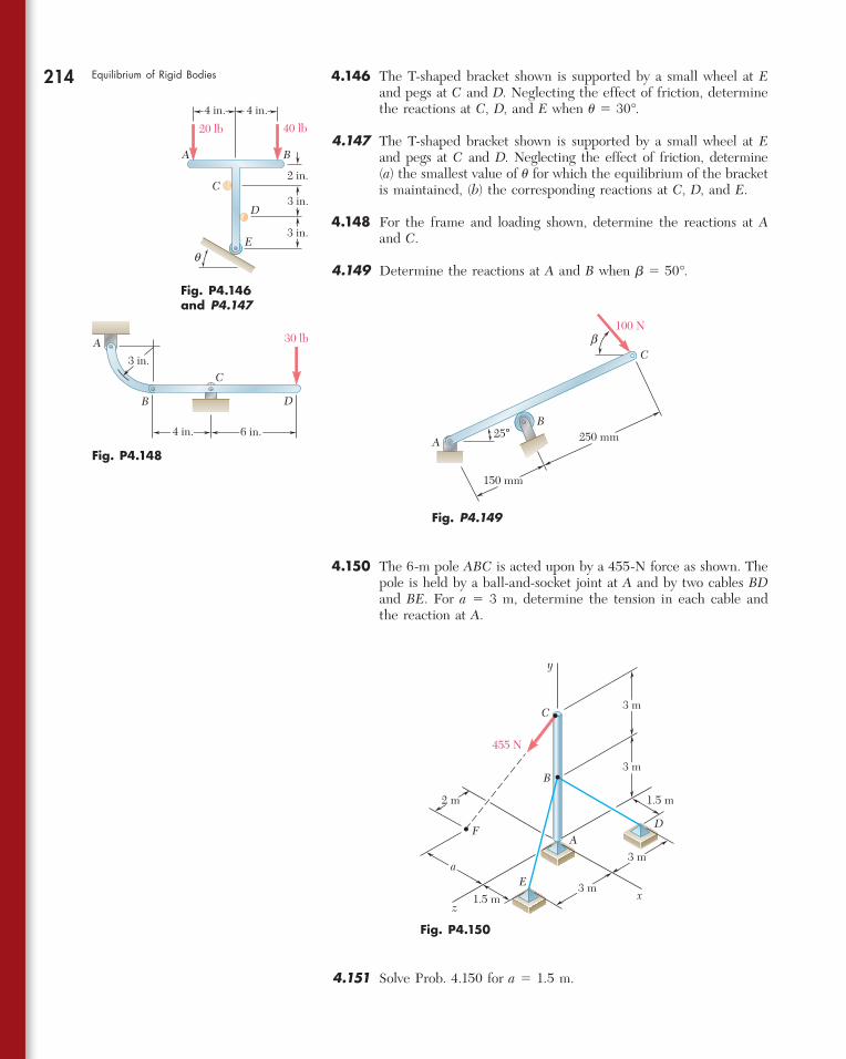
214 Equilibrium of Rigid Bodies 4.146 The T-shaped bracket shown is supported by a small wheel at E and pegs at C and D. Neglecting the effect of friction, determine the reactions at C, D, and E when u 5 30°.
4.147 The T-shaped bracket shown is supported by a small wheel at E and pegs at C and D. Neglecting the effect of friction, determine (a) the smallest value of u for which the equilibrium of the bracket is maintained, (b) the corresponding reactions at C, D, and E.
4.148 For the frame and loading shown, determine the reactions at A and C.
4.149 Determine the reactions at A and B when b 5 50°.
A B
C
D
E3 in.
3 in.
2 in.
20 lb 40 lb
q
4 in. 4 in.
Fig. P4.146 and P4.147
4.150 The 6-m pole ABC is acted upon by a 455-N force as shown. The pole is held by a ball-and-socket joint at A and by two cables BD and BE. For a 5 3 m, determine the tension in each cable and the reaction at A.
A
B
C
D
30 lb
4 in. 6 in.
3 in.
Fig. P4.148A
B
C
100 N
250 mm
150 mm
25°
b
Fig. P4.149
A
B
C
F
x
y
z
D
E
455 N
1.5 m
1.5 m
a
2 m
3 m
3 m
3 m
3 m
Fig. P4.150
4.151 Solve Prob. 4.150 for a 5 1.5 m.
bee29400_ch04_156-217.indd Page 214 11/29/08 3:34:13 PM user-s172bee29400_ch04_156-217.indd Page 214 11/29/08 3:34:13 PM user-s172 /Volumes/204/MHDQ076/work%0/indd%0/Volumes/204/MHDQ076/work%0/indd%0
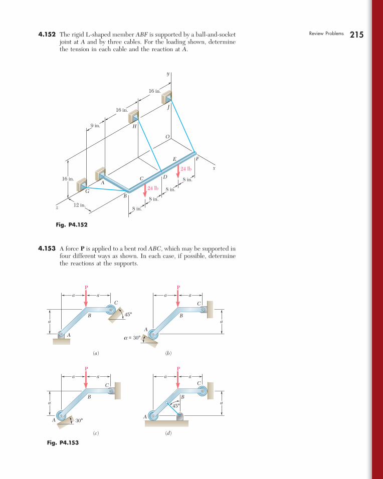
215Review Problems 4.152 The rigid L-shaped member ABF is supported by a ball-and-socket joint at A and by three cables. For the loading shown, determine the tension in each cable and the reaction at A.
AA
B B
C C
P
A
B
C
P
P
A
B
C
P
45°
45°
(a) (b)
(c) (d)
a = 30°
30°
aa
a
aa
a
aa
a
aa
a
Fig. P4.153
x
y
z
A
B
C D
E F
G
J
H
24 lb
24 lb
9 in.
16 in.
16 in.
8 in.
12 in.
16 in.
8 in.
8 in.
8 in.
O
Fig. P4.152
4.153 A force P is applied to a bent rod ABC, which may be supported in four different ways as shown. In each case, if possible, determine the reactions at the supports.
bee29400_ch04_156-217.indd Page 215 11/29/08 3:34:13 PM user-s172bee29400_ch04_156-217.indd Page 215 11/29/08 3:34:13 PM user-s172 /Volumes/204/MHDQ076/work%0/indd%0/Volumes/204/MHDQ076/work%0/indd%0
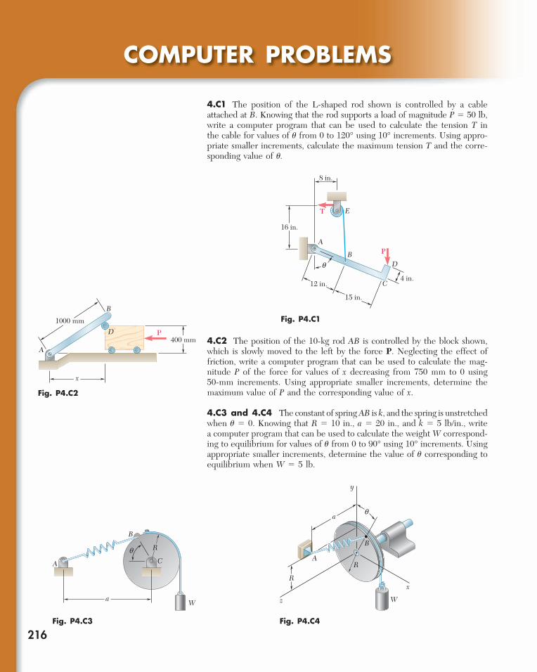
216
COMPUTER PROBLEMS
4.C1 The position of the L-shaped rod shown is controlled by a cable attached at B. Knowing that the rod supports a load of magnitude P 5 50 lb, write a computer program that can be used to calculate the tension T in the cable for values of u from 0 to 120° using 10° increments. Using appro-priate smaller increments, calculate the maximum tension T and the corre-sponding value of u.
Fig. P4.C1
E
A
BD
C
T
P
q
8 in.
16 in.
12 in.
15 in.
4 in.
A
B
D P400 mm
x
1000 mm
Fig. P4.C2
W
A
a
q
B
C
R
Fig. P4.C3
R
B
R
A
W
a
y
z
x
q
Fig. P4.C4
4.C2 The position of the 10-kg rod AB is controlled by the block shown, which is slowly moved to the left by the force P. Neglecting the effect of friction, write a computer program that can be used to calculate the mag-nitude P of the force for values of x decreasing from 750 mm to 0 using 50-mm increments. Using appropriate smaller increments, determine the maximum value of P and the corresponding value of x.
4.C3 and 4.C4 The constant of spring AB is k, and the spring is unstretched when u 5 0. Knowing that R 5 10 in., a 5 20 in., and k 5 5 lb/in., write a computer program that can be used to calculate the weight W correspond-ing to equilibrium for values of u from 0 to 90° using 10° increments. Using appropriate smaller increments, determine the value of u corresponding to equilibrium when W 5 5 lb.
bee29400_ch04_156-217.indd Page 216 11/29/08 3:34:14 PM user-s172bee29400_ch04_156-217.indd Page 216 11/29/08 3:34:14 PM user-s172 /Volumes/204/MHDQ076/work%0/indd%0/Volumes/204/MHDQ076/work%0/indd%0
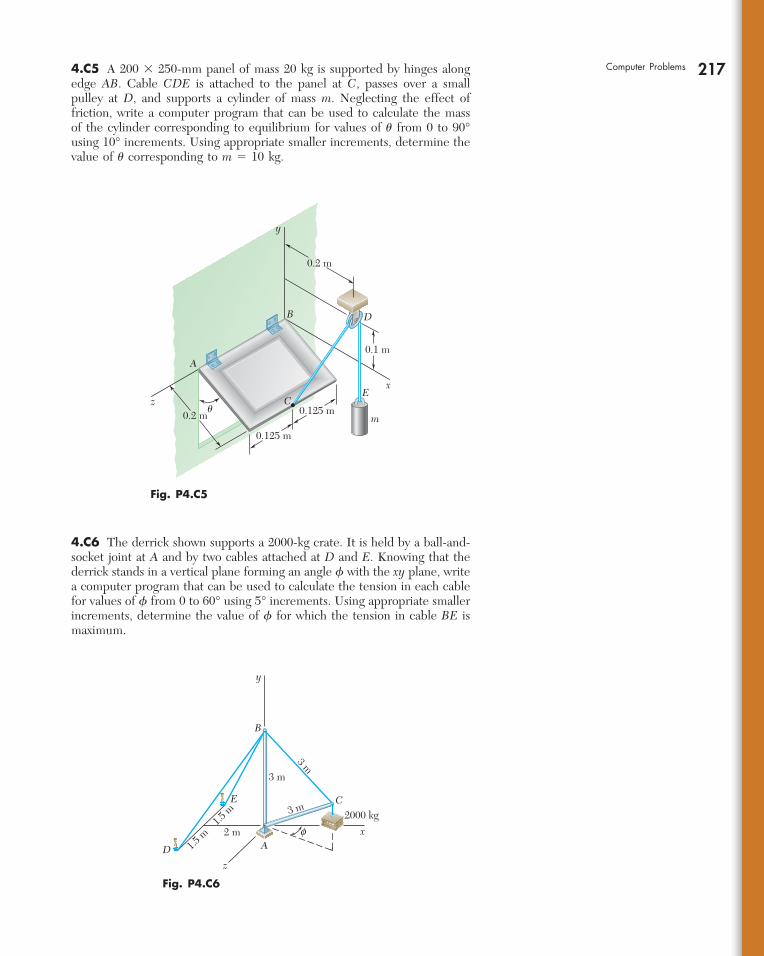
217Computer Problems 4.C5 A 200 3 250-mm panel of mass 20 kg is supported by hinges along edge AB. Cable CDE is attached to the panel at C, passes over a small pulley at D, and supports a cylinder of mass m. Neglecting the effect of friction, write a computer program that can be used to calculate the mass of the cylinder corresponding to equilibrium for values of u from 0 to 90° using 10° increments. Using appropriate smaller increments, determine the value of u corresponding to m 5 10 kg.
0.2 m
0.2 m
0.1 m
0.125 m
0.125 m
A
B
C
D
Ez
x
y
�m
Fig. P4.C5
y
x
z
B
E
D
C
Af
2000 kg
3 m
3 m
2 m1.5
m
1.5 m
3 m
Fig. P4.C6
4.C6 The derrick shown supports a 2000-kg crate. It is held by a ball-and-socket joint at A and by two cables attached at D and E. Knowing that the derrick stands in a vertical plane forming an angle f with the xy plane, write a computer program that can be used to calculate the tension in each cable for values of f from 0 to 60° using 5° increments. Using appropriate smaller increments, determine the value of f for which the tension in cable BE is maximum.
bee29400_ch04_156-217.indd Page 217 11/29/08 3:34:16 PM user-s172bee29400_ch04_156-217.indd Page 217 11/29/08 3:34:16 PM user-s172 /Volumes/204/MHDQ076/work%0/indd%0/Volumes/204/MHDQ076/work%0/indd%0

The Revelstoke Dam, located on the
Columbia River in British Columbia, is
subjected to three different kinds of
distributed forces: the weights of its
constituent elements, the pressure forces
exerted by the water of its submerged
face, and the pressure forces exerted
by the ground on its base.
218
bee29400_ch05_218-283.indd Page 218 11/29/08 4:53:37 PM user-s172bee29400_ch05_218-283.indd Page 218 11/29/08 4:53:37 PM user-s172 /Volumes/204/MHDQ076/work%0/indd%0/Volumes/204/MHDQ076/work%0/indd%0